aisladores ohio brass
TRANSCRIPT

A
26-
OHIO BRASS – AIKEN, SC JULY 2006
® ®
POWER SYSTEMS, INC.
Printed in USA
Section
26
Hi*Lite® XL Transmission Insulators

OHIO BRASS – AIKEN, SC
26-2
JULY 2006
® ®
POWER SYSTEMS, INC.
©Copyright 2006 Hubbell/Ohio Brass • 1850 Richland Avenue, East • Aiken, SC 29801NOTE: Because Hubbell has a policy of continuous product improvement, we reserve the right to change design and specifications without notice.
Warranty - MaterialHubbell Power Systems, Inc. warrants all products sold by it to be merchantable (as such term is defined in the Uniform Commercial Code) and to be free from defects in material and workmanship. Buyer must notify the Company promptly of any claim under this warranty. The Buyer's exclusive remedy for breach of this warranty shall be the repair or replacement, F.O.B. factory, at the Company's option, of any product defective under the warranty which is returned to the Company within one year from the date of shipment. NO OTHER WARRANTY, WHETHER EXPRESS OR ARISING BY OPERATION OF LAW, COURSE OF DEALING, USAGE OF TRADE OR OTHERWISE IMPLIED, SHALL EXIST IN CONNECTION WITH THE COMPANY'S PRODUCTS OR ANY SALE OR USE THEREOF. The Company shall in no event be liable for any loss of profits or any consequential or special damages incurred by Buyer. The Company's warranty shall run only to the first Buyer of a product from the Company, from the Company's distributor, or from an original equipment manufacturer reselling the Company's product, and is
non-assignable and non-transferable and shall be of no force and effect if asserted by any per-son other than such first Buyer. This warranty applies only to the use of the product as intended by Seller and does not cover any misapplication or misuse of said product.
Warranty - ApplicationHubbell Power Systems, Inc. does not warrant the accuracy of and results from product or system performance recommendations resulting from any engineering analysis or study. This applies regardless of whether a charge is made for the recommendation, or if it is provided free of charge.
Responsibility for selection of the proper product or application rests solely with the purchaser. In the event of errors or inaccuracies determined to be caused by Hubbell Power Systems, Inc., its liability will be limited to the re-performance of any such analysis or study.
A
26-
OHIO BRASS – AIKEN, SC JULY 2006
® ®
POWER SYSTEMS, INC.
A
B
C
D
E
Hi*Lite® XL Transmission Insulators
Section26
Suspensions
Line Posts
Braced Posts
Station Posts
Sample Polymer Specs
OHIO BRASS – AIKEN, SC
26-
JULY 2006
® ®
POWER SYSTEMS, INC.

A
26-
OHIO BRASS – AIKEN, SC JULY 2006
® ®
POWER SYSTEMS, INC.
®
Table of ContentsPage
Design .............................................................. 26-6Rod ................................................................... 26-6End Fittings....................................................... 26-6Weathersheds .................................................. 26-6Interface............................................................ 26-6Leakage Distance ............................................. 26-6Washability ....................................................... 26-6Mechanical Ratings .......................................... 26-6Lengths Available ............................................. 26-6Product Updates ............................................... 26-6Packaging ......................................................... 26-6Corona Performance ........................................ 26-7Hi*Lite XL 25k SML Data .................................. 26-8Hi*Lite XL 30k SML Data .................................. 26-9Hi*Lite XL 50k SML Data ................................ 26-10End Fitting Detail ............................................ 26-11Key to the Catalog Numbers .......................... 26-11
Hi*Lite XLSuspension Insulators
OHIO BRASS – AIKEN, SC
26-6
JULY 2006
® ®
POWER SYSTEMS, INC.
Hi*Lite® XL InsulatorsHi*Lite XL suspension insulators in this publication em-body the latest features available in polymer insulator design and manufacture.From the early prototypes in 1971, through full scale introduction in 1976, and through the succeeding years, Hi*Lite insulators have featured conservative design and high-quality manufacture.Today’s Hi*Lite insulators will add to the over 1,000,000 already in service worldwide.
Design
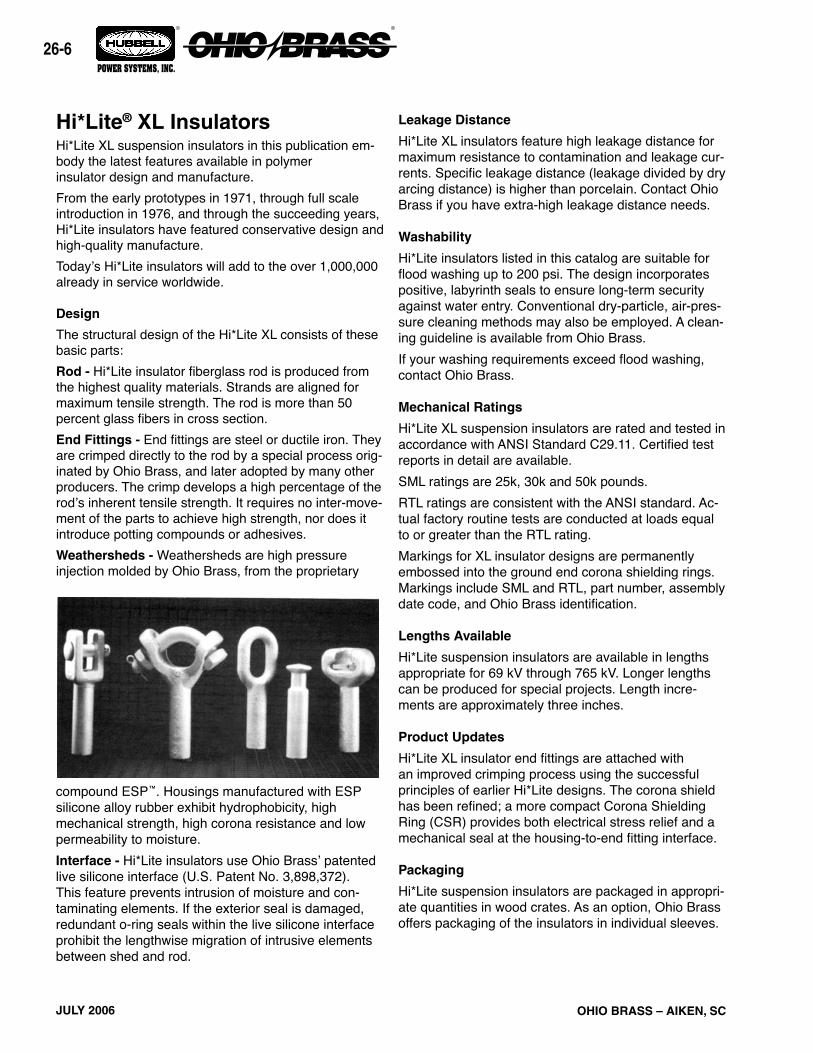
The structural design of the Hi*Lite XL consists of these basic parts:Rod - Hi*Lite insulator fiberglass rod is produced from the highest quality materials. Strands are aligned for maximum tensile strength. The rod is more than 50 percent glass fibers in cross section.End Fittings - End fittings are steel or ductile iron. They are crimped directly to the rod by a special process orig-inated by Ohio Brass, and later adopted by many other producers. The crimp develops a high percentage of the rod’s inherent tensile strength. It requires no inter-move-ment of the parts to achieve high strength, nor does it introduce potting compounds or adhesives.Weathersheds - Weathersheds are high pressure injection molded by Ohio Brass, from the proprietary
compound ESP™. Housings manufactured with ESP silicone alloy rubber exhibit hydrophobicity, high mechanical strength, high corona resistance and low permeability to moisture.Interface - Hi*Lite insulators use Ohio Brass’ patented live silicone interface (U.S. Patent No. 3,898,372). This feature prevents intrusion of moisture and con-taminating elements. If the exterior seal is damaged, redundant o-ring seals within the live silicone interface prohibit the lengthwise migration of intrusive elements between shed and rod.
Leakage Distance
Hi*Lite XL insulators feature high leakage distance for maximum resistance to contamination and leakage cur-rents. Specific leakage distance (leakage divided by dry arcing distance) is higher than porcelain. Contact Ohio Brass if you have extra-high leakage distance needs.
Washability
Hi*Lite insulators listed in this catalog are suitable for flood washing up to 200 psi. The design incorporates positive, labyrinth seals to ensure long-term security against water entry. Conventional dry-particle, air-pres-sure cleaning methods may also be employed. A clean-ing guideline is available from Ohio Brass.If your washing requirements exceed flood washing, contact Ohio Brass.
Mechanical Ratings
Hi*Lite XL suspension insulators are rated and tested in accordance with ANSI Standard C29.11. Certified test reports in detail are available.SML ratings are 25k, 30k and 50k pounds. RTL ratings are consistent with the ANSI standard. Ac-tual factory routine tests are conducted at loads equal to or greater than the RTL rating.Markings for XL insulator designs are permanently embossed into the ground end corona shielding rings. Markings include SML and RTL, part number, assembly date code, and Ohio Brass identification.
Lengths Available
Hi*Lite suspension insulators are available in lengths appropriate for 69 kV through 765 kV. Longer lengths can be produced for special projects. Length incre-ments are approximately three inches.
Product Updates
Hi*Lite XL insulator end fittings are attached with an improved crimping process using the successful principles of earlier Hi*Lite designs. The corona shield has been refined; a more compact Corona Shielding Ring (CSR) provides both electrical stress relief and a mechanical seal at the housing-to-end fitting interface.
Packaging
Hi*Lite suspension insulators are packaged in appropri-ate quantities in wood crates. As an option, Ohio Brass offers packaging of the insulators in individual sleeves.
A
26-
OHIO BRASS – AIKEN, SC JULY 2006
® ®
POWER SYSTEMS, INC.
Normal Applications: Top Grounded, Bottom Energized
Orientation
TopBottom
TopBottom
Insulator
Suspension25/30 K SMLSuspension50 K SML
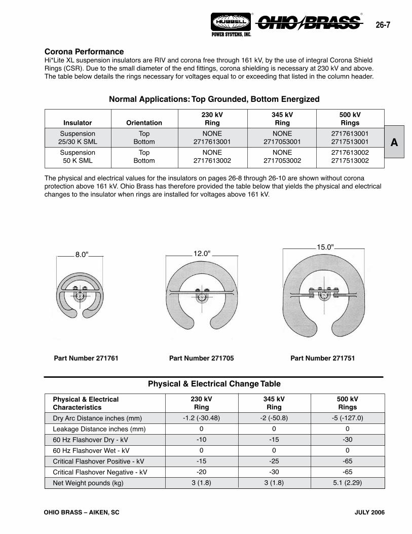
The physical and electrical values for the insulators on pages 26-8 through 26-10 are shown without corona protection above 161 kV. Ohio Brass has therefore provided the table below that yields the physical and electrical changes to the insulator when rings are installed for voltages above 161 kV.
Corona PerformanceHi*Lite XL suspension insulators are RIV and corona free through 161 kV, by the use of integral Corona Shield Rings (CSR). Due to the small diameter of the end fittings, corona shielding is necessary at 230 kV and above. The table below details the rings necessary for voltages equal to or exceeding that listed in the column header.
Physical & Electrical Change Table
500 kVRings
-5 (-127.0)0
-300
-65-65
5.1 (2.29)
345 kVRing
-2 (-50.8)0
-150
-25-30
3 (1.8)
230 kVRing
-1.2 (-30.48)0
-100
-15-20
3 (1.8)
Physical & ElectricalCharacteristics
Dry Arc Distance inches (mm)Leakage Distance inches (mm)60 Hz Flashover Dry - kV60 Hz Flashover Wet - kVCritical Flashover Positive - kVCritical Flashover Negative - kVNet Weight pounds (kg)
Part Number 271761 Part Number 271705 Part Number 271751
15.0"12.0"8.0"
500 kVRings
2717613001271751300127176130022717513002
345 kVRing
NONE2717053001
NONE2717053002
230 kVRing
NONE2717613001
NONE2717613002

OHIO BRASS – AIKEN, SC
26-
JULY 2006
® ®
POWER SYSTEMS, INC.
kg
-.11-.11-.01-.07
0-.007
GroundFitting
EyeEye
SocketClevis
Y-ClevisClevis
LineFitting
BallEyeBallBallEyeEye
SuffixCode
100110001301140112001400
Inches
-.061.28-.97
-1.001.34.34
mm
-1.532.5-24.6-25.434.08.6
Pounds
-2.5-2.5-.05-.15
0-.15
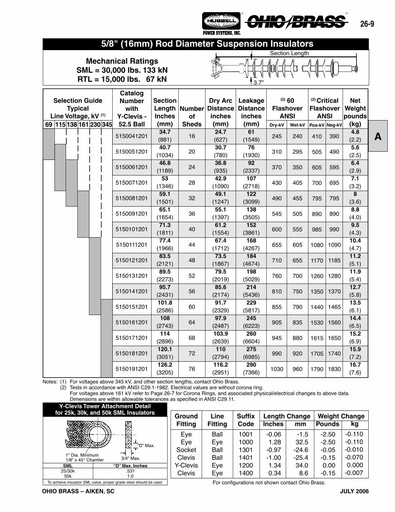
Weight ChangeLength Change
For configurations not shown contact Ohio Brass.
Mechanical RatingsSML = 25,000 lbs. 111 kNRTL = 12,500 lbs. 56 kN
NetWeightpounds
(kg)4.8
(2.2)5.6
(2.5)6.4
(2.9)7.1
(3.2)8.0
(3.6)8.8
(4.0)9.5
(4.3)10.4(4.7)11.2(5.1)11.9(5.4)12.7(5.8)13.5(6.1)14.4(6.5)15.2(6.9)15.9(7.2)16.7(7.6)
(2) CriticalFlashover
ANSI
CatalogNumber
withY-Clevis -52.5 Ball
5110041201
5110051201
5110061201
5110071201
5110081201
5110091201
5110101201
5110111201
5110121201
5110131201
5110141201
5110151201
5110161201
5110171201
5110181201
5110191201
Neg-kV
390
490
595
695
795
890
990
1090
1185
1280
1370
1465
1560
1650
1740
1830
Pos-kV
410
505
605
700
795
890
985
1080
1170
1260
1350
1440
1530
1615
1705
1790
Wet-kV
240
295
350
405
455
505
555
605
655
700
750
790
835
880
920
960
Dry-kV
245
310
370
430
490
545
600
655
710
760
810
855
905
945
990
1030
(2) 60 Flashover
ANSI
LeakageDistanceinches(mm)
61(1549)
76(1930)
92(2337)
107(2718)
122(3099)
138(3505)
152(3861)
168(4267)
184(4674)
198(5029)
214(5436)
229(5817)
245(6223)
260(6604)
275(6985)
290(7366)
Dry ArcDistanceinches(mm)24.7(627)30.7(780)36.8(935)42.9
(1090)49.1
(1247)55.1
(1397)61.2
(1554)67.4
(1712)73.5
(1867)79.5
(2019)85.6
(2174)91.7
(2329)97.9
(2487)103.9(2639)110.0(2794)116.2(2951)
Numberof
Sheds
16
20
24
28
32
36
40
44
48
52
56
60
64
68
72
76
SectionLengthInches(mm)34.7(881)40.7
(1034)46.8
(1189)53.0
(1346)59.1
(1501)65.1
(1654)71.3
(1811)77.4
(1966)83.5
(2121)89.5
(2273)95.7
(2431)101.8(2586)108.0(2743)114.0(2896)120.1(3051)126.2(3205)
69 345230138 161115
Selection GuideTypical
Line Voltage, kV (1)
Notes: (1) For voltages above 345 kV, and other section lengths, contact Ohio Brass. (2) Tests in accordance with ANSI C29.1-1982. Electrical values are without corona ring. For voltages above 161 kV refer to Page 26-7 for Corona Rings, and associated physical/electrical changes to above data. Dimensions are within allowable tolerances as specified in ANSI C29.11.
5/8" (16mm) Rod Diameter Suspension InsulatorsSection Length
3.7"
A
26-
OHIO BRASS – AIKEN, SC JULY 2006
® ®
POWER SYSTEMS, INC.
kg
-0.110-0.110-0.010-0.0700.000
-0.007
GroundFitting
EyeEye
SocketClevis
Y-ClevisClevis
LineFitting
BallEyeBallBallEyeEye
SuffixCode
100110001301140112001400
Inches
-0.06 1.28 -0.97 -1.00 1.34 0.34
mm
-1.532.5
-24.6-25.434.0
8.6
Pounds
-2.50-2.50-0.05-0.150.00
-0.15
Weight ChangeLength Change
For configurations not shown contact Ohio Brass.
Y-Clevis Tower Attachment Detailfor 25k, 30k, and 50k SML Insulators
SML25/30k
50k
“D” Max. Inches.5311.0
To achieve insulator SML value, proper grade steel should be used
Mechanical RatingsSML = 30,000 lbs. 133 kNRTL = 15,000 lbs. 67 kN
NetWeightpounds
(kg)4.8
(2.2)5.6
(2.5)6.4
(2.9)7.1
(3.2)8
(3.6)8.8
(4.0)9.5
(4.3)10.4(4.7)11.2(5.1)11.9(5.4)12.7(5.8)13.5(6.1)14.4(6.5)15.2(6.9)15.9(7.2)16.7(7.6)
(2) CriticalFlashover
ANSI
CatalogNumber
withY-Clevis -52.5 Ball
5150041201
5150051201
5150061201
5150071201
5150081201
5150091201
5150101201
5150111201
5150121201
5150131201
5150141201
5150151201
5150161201
5150171201
5150181201
5150191201
Neg-kV
390
490
595
695
795
890
990
1090
1185
1280
1370
1465
1560
1650
1740
1830
Pos-kV
410
505
605
700
795
890
985
1080
1170
1260
1350
1440
1530
1615
1705
1790
Wet-kV
240
295
350
405
455
505
555
605
655
700
750
790
835
880
920
960
Dry-kV
245
310
370
430
490
545
600
655
710
760
810
855
905
945
990
1030
(2) 60 Flashover
ANSI
LeakageDistanceinches(mm)
61(1549)
76(1930)
92(2337)
107(2718)
122(3099)
138(3505)
152(3861)
168(4267)
184(4674)
198(5029)
214(5436)
229(5817)
245(6223)
260(6604)
275(6985)
290(7366)
Dry ArcDistanceinches(mm)24.7(627)30.7(780)36.8(935)42.9
(1090)49.1
(1247)55.1
(1397)61.2
(1554)67.4
(1712)73.5
(1867)79.5
(2019)85.6
(2174)91.7
(2329)97.9
(2487)103.9(2639)
110(2794)116.2(2951)
Numberof
Sheds
16
20
24
28
32
36
40
44
48
52
56
60
64
68
72
76
SectionLengthInches(mm)34.7(881)40.7
(1034)46.8
(1189)53
(1346)59.1
(1501)65.1
(1654)71.3
(1811)77.4
(1966)83.5
(2121)89.5
(2273)95.7
(2431)101.8(2586)
108(2743)
114(2896)120.1(3051)126.2(3205)
69 345230138 161115
Selection GuideTypical
Line Voltage, kV (1)
Notes: (1) For voltages above 345 kV, and other section lengths, contact Ohio Brass. (2) Tests in accordance with ANSI C29.1-1982. Electrical values are without corona ring. For voltages above 161 kV refer to Page 26-7 for Corona Rings, and associated physical/electrical changes to above data. Dimensions are within allowable tolerances as specified in ANSI C29.11.
Section Length
3.7"
5/8" (16mm) Rod Diameter Suspension Insulators
“D” Max.
3/4" Max.1" Dia. Minimum1/8" x 45° Chamfer

OHIO BRASS – AIKEN, SC
26-0
JULY 2006
® ®
POWER SYSTEMS, INC.
End Fitting ExampleYou need the electrical and mechanical characteristics of Catalog #5130101001. But, a Y-clevis is needed at the ground end instead of an eye. From the table at the right, find the code for the Y-clevis/ball configura-tion 1201. You should order Catalog #5130101201. The same process is used for 5/8" (25k) and 7/8" (30k) insulators.
kg
.18-.18.180
GroundFitting
Y-ClevisEye
SocketY-Clevis
LineFitting
BallEyeBallEye
SuffixCode
1201100013011200
Inches
-.581.26-.72-.58
mm
-14.732.0-18.3-14.7
Pounds
.4-.4.40
Weight ChangeLength Change
Mechanical RatingsSML = 50,000 lbs. 222 kNRTL = 25,000 lbs. 111 kN
For configurations not shown contact Ohio Brass.
7/8" (22mm) Rod Diameter Suspension Insulators
NetWeightpounds
(kg)12.7(5.8)13.7(6.2)14.8(6.7)15.9(7.2)16.9(7.7)19.1(8.7)20.2(9.2)21.2(9.6)24.4
(11.1)24.5
(11.1)25.5
(11.6)27.6
(12.5)29.8
(13.5)31.9
(14.5)34.0
(15.4)35.1
(15.9)
(2) CriticalFlashover
ANSI
CatalogNumber
withChain Eye -52.11 Ball
5130071001
5130081001
5130091001
5130101001
5130111001
5130131001
5130141001
5130151001
5130171001
5130181001
5130191001
5130211001
5130231001
5130251001
5130271001
5130281001
Neg-kV
695
795
890
990
1090
1280
1370
1465
1650
1740
1830
2005
2175
2345
2510
2590
Pos-kV
700
795
890
985
1080
1260
1350
1440
1615
1705
1790
1960
2125
2285
2445
2520
Wet-kV
400
455
505
555
605
700
745
790
875
915
955
1035
1105
1175
1240
1270
Dry-kV
430
490
545
600
655
760
810
855
945
990
1030
1110
1180
1245
1305
1330
(2) 60 Flashover
ANSI
LeakageDistanceinches(mm)106
(2692)121
(3073)136
(3454)151
(3835)167
(4242)197
(5004)212
(5385)228
(5791)258
(6553)273
(6934)288
(7315)319
(8103)349
(8885)379
(9627)410
(10414)425
(10795)
Dry ArcDistanceinches(mm)42.9
(1090)49.0
(1245)55.0
(1397)61.2
(1554)67.3
(1709)79.5
(2019)85.6
(2174)91.7
(2329)103.9(2639)110.0(2794)116.2(2951)128.3(3259)140.6(3271)152.7(3879)165.0(4191)171.1(4346)
Numberof
Sheds
28
32
36
40
44
52
56
60
68
72
76
84
92
100
108
112
SectionLengthInches(mm)55.8
(1417)62.0
(1574)68.0
(1727)74.1
(1882)80.3
(2040)92.4
(2347)98.5
(2502)104.7(2659)116.8(2967)123.0(3124)129.1(3279)141.2(3586)153.5(3899)165.7(4209)177.9(4519)184.1(4676)
115 500345161 230138
Selection GuideTypical
Line Voltage, kV (1)
Notes: (1) For voltages above 500 kV, and other section lengths, contact Ohio Brass. (2) Tests in accordance with ANSI C29.1-1982. Electrical values are without corona ring. For voltages above 161 kV refer to Page 26-7 for Corona Rings, and associated physical/electrical changes to above data. Dimensions are within allowable tolerances as specified in ANSI C29.11.
Section Length
4.0"

A
26-
OHIO BRASS – AIKEN, SC JULY 2006
® ®
POWER SYSTEMS, INC.
ANSI Clevis
SMLk-LB (kN)
25 (111) - 30 (133) 50 (222)
25 (111) - 30 (133)50 (222)
25 (111) - 30 (133)50 (222)
25 (111) - 30 (133)
ANSICLASS
--
52-552-11
--
52-6
A0.620.750.730.920.750.880.62
D0.620.85
----
1.10
C2.002.00
----
1.50
B1.001.001.291.631.531.590.75
FITTINGTYPE
CHAIN EYE
BALL & SOCKET
Y-CLEVIS
CLEVIS
DIMENSIONS IN. (mm)
5 1 1 1 1 10 02 2Line End Fittings
Chain Eye .................................00ANSI Ball (1) .............................01Y-Clevis ....................................02ANSI Socket (1) ........................03ANSI Straight Clevis .................04
Ground End FittingsChain Eye ...................................0ANSI Ball (1) ...............................1Y-Clevis ......................................2ANSI Socket (1) ..........................3ANSI Straight Clevis ...................4
Labeling1 = English2 = Metric (2)R = English w/8" Corona RingW = English w/12" Corona RingT = English w/15" and 8" Corona Ring
Hi*Lite XL
Hi*Lite XL Suspension Insulators:Key to the Catalog Numbers
Strength1 = 25K SML5 = 30K SML3 = 50K SML
Construction0 = Standard Hardware/0 Added Sheds1 = Dull Hardware/0 Added Sheds2 = Standarad Hardware/2 Added Sheds3 = Dull Hardware/2 Added Sheds
Most Common End Fittings
* For IEC 16mm and 20mm Ball and Socket fittings, contact Ohio Brass.
Weathershed ConfigurationNumber of sheds equals this number times four, plus any added sheds listed in the construction digit.
ANSI Sock-Y-Clevis FittingANSI Ball*Chain Eye
(1) For IEC Ball and Socket fittings, contact Ohio Brass.(2) Metric labeling of ANSI, or IEC insulators.

OHIO BRASS – AIKEN, SC
26-2
JULY 2006
® ®
POWER SYSTEMS, INC.

26-
OHIO BRASS – AIKEN, SC JULY 2006
® ®
POWER SYSTEMS, INC.
B
Hi*Lite® XLLine Post Insulators
Table of ContentsPage
Design ............................................................ 26-14Rod ................................................................. 26-14End Fittings..................................................... 26-14Weathersheds ................................................ 26-14Interface.......................................................... 26-14Leakage Distance ........................................... 26-14Washability ..................................................... 26-14Mechanical Ratings ........................................ 26-14Corona Rings.................................................. 26-15Packaging ....................................................... 26-15Key to 2.5" Catalog Numbers ......................... 26-15Hi*Lite XL 2.5" Rod Horizontal Line Posts ...... 26-16Hi*Lite XL 2.5" Rod Vertical Line Posts .......... 26-17Hi*Lite XL 2.5" Rod Vertical Line Post Assembly..................................................... 26-18Hi*Lite XL 2.5" Rod Base Fittings ................... 26-19Hi*Lite XL 2.5" Rod Line Fittings .................... 26-20Hi*Lite XL 3.0" Rod Horizontal Line Posts ...... 26-21Key to 3.0" Catalog Numbers ......................... 26-21Hi*Lite II 3.0" Rod Horizontal Line Posts ........ 26-22Hi*Lite II 3.0" Rod Vertical Line Posts ............ 26-23Hi*Lite XL 3.0" Rod. Dia. Base Fittings ........... 26-24Hi*Lite XL 3.0" Rod. Dia. Line Fittings ............ 26-25Clamps and Assemblies ................................. 26-26

OHIO BRASS – AIKEN, SC
26-
JULY 2006
® ®
POWER SYSTEMS, INC.
Hi*Lite*® XL InsulatorsHi*Lite XL line post insulators in this publication em-body the latest features available in polymer insulator design and manufacture.From the early prototypes in 1971, through full scale in-troduction in 1976, and through the succeeding years, Hi*Lite insulators have featured conservative design and high-quality manufacture.Today’s Hi*Lite insulators will add to the over 1,000,000 already in service worldwide.Design
The structural design of the Hi*Lite XL consists of these basic parts:Rod - Hi*Lite insulator fiberglass rod is produced from the highest quality materials. Strands are aligned for maximum tensile strength. The rod is more than 50 per-cent glass fibers in cross section.End Fittings - End fittings are aluminum or ductile iron. They are crimped directly to the rod by a special process originated by Ohio Brass, and later adopted by many other producers. The crimp requires no inter-movement of the parts to achieve high strength, nor does it introduce potting compounds or adhesives.Weathersheds - Weathersheds are high pressure injection molded by Ohio Brass, from the proprietary compound ESP™. Housings manufactured with ESP silicone alloy rubber exhibit hydrophobicity, high mechanical strength, high corona resistance and low permeability to moisture.Interface - Hi*Lite insulators use Ohio Brass’ patented live silicone interface (U.S. Patent No. 3,898,372). This feature prevents intrusion of moisture and con-taminating elements. If the exterior seal is damaged, redundant o-ring seals within the live silicone interface prohibit the lengthwise migration of intrusive elements between shed and rod.Leakage Distance
Hi*Lite XL insulators feature high leakage distance for maximum resistance to contamination and leakage currents.Washability
Hi*Lite Line Post insulators listed in this catalog are suitable for flood washing up to 200 psi. The design in-corporates positive, labyrinth seals to ensure long-term security against water entry. Conventional dry-particle, air-pressure cleaning methods may also be employed. A cleaning guideline is available from Ohio Brass.If your washing requirements exceed flood washing, contact Ohio Brass.
Mechanical Ratings
Line post insulators are basically cantilever support members, with ratings defined as follows:Specified Cantilever Load (SCL)
SCL is the ultimate cantilever strength rating of the Hi*Lite XL line post insulator. SCL is identical to the minimum average breaking load (ABL) rating in previ-ous catalogs.Reference Cantilever Load (RCL)
RCL is the maximum recommended load in cantilever that a Hi*Lite XL post insulator is designed to withstand during its life, and is equal to 50% of the SCL. RCL is identical to maximum working load (MWL) listed in previous catalogs. Line design loads applied to post insulators often include tension, or compression, in ad-dition to the primary vertical cantilever load. In addition, some longitudinal load is usually designed for as well.Combined Load
Contact your Hubbell Power Systems representative for combined load applications.
26-
OHIO BRASS – AIKEN, SC JULY 2006
® ®
POWER SYSTEMS, INC.
B
5 2 2 0 1 00 08 1Hi*Lite XLXL Post
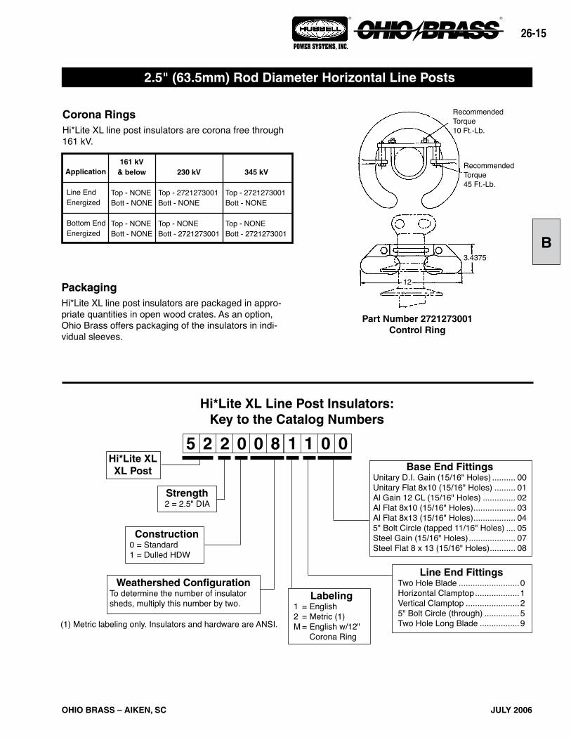
Strength2 = 2.5" DIA
Construction0 = Standard1 = Dulled HDW
Weathershed ConfigurationTo determine the number of insulator sheds, multiply this number by two.
Hi*Lite XL Line Post Insulators:Key to the Catalog Numbers
Line End FittingsTwo Hole Blade ..........................0Horizontal Clamptop ...................1Vertical Clamptop .......................25" Bolt Circle (through) ...............5Two Hole Long Blade .................9
2.5" (63.5mm) Rod Diameter Horizontal Line Posts
Corona RingsHi*Lite XL line post insulators are corona free through 161 kV.
PackagingHi*Lite XL line post insulators are packaged in appro-priate quantities in open wood crates. As an option, Ohio Brass offers packaging of the insulators in indi-vidual sleeves.
Part Number 2721273001Control Ring
Application
Line EndEnergized
Bottom EndEnergized
230 kV
Top - 2721273001Bott - NONE
Top - NONEBott - 2721273001
161 kV & below
Top - NONEBott - NONE
Top - NONEBott - NONE
345 kV
Top - 2721273001Bott - NONE
Top - NONEBott - 2721273001
Base End FittingsUnitary D.I. Gain (15/16" Holes) .......... 00Unitary Flat 8x10 (15/16" Holes) ......... 01Al Gain 12 CL (15/16" Holes) .............. 02Al Flat 8x10 (15/16" Holes) .................. 03Al Flat 8x13 (15/16" Holes) .................. 045" Bolt Circle (tapped 11/16" Holes) .... 05Steel Gain (15/16" Holes) .................... 07Steel Flat 8 x 13 (15/16" Holes) ........... 08
RecommendedTorque10 Ft.-Lb.
RecommendedTorque45 Ft.-Lb.
3.4375
12
(1) Metric labeling only. Insulators and hardware are ANSI.
Labeling1 = English2 = Metric (1)M = English w/12" Corona Ring

OHIO BRASS – AIKEN, SC
26-16
AUGUST 2007
® ®
POWER SYSTEMS, INC.
69 345230138 161115
Selection GuideTypical
Line Voltage, kV
Notes: (1) Tests in accordance with ANSI C29.1-1982. Electrical values are without corona ring. (2) RCL is the maximum continuous load at which the post should be applied. For voltages above 161 kV refer to Page 26-15 for Corona Rings. Dimensions are within allowable tolerances as specified in ANSI C29.11.
“X”LengthInches(mm)33.5(851)38.6(980)43.9
(1115)49.2
(1250)54.5
(1384)59.6
(1514)64.8
(1646)70.1
(1781)75.4
(1915)80.5
(2045)85.8
(2180)91.1
(2314)96.3
(2446)101.4(2575)106.7(2710)112.0(2845)
Catalog #with
Gain Base& ClamptopEnd Fittings
5220041100
5220051100
5220061100
5220071100
5220081100
5220091100
5220101100
5220111100
5220121100
5220131100
5220141100
5220151100
5220161100
5220171100
5220181100
5220191100
No.of
Sheds
8
10
12
14
16
18
20
22
24
26
28
30
32
34
36
38
Dry ArcDistanceinches(mm)
23(584)
28(711)
33(838)
39(991)
44(1118)
49(1245)
55(1397)
60(1524)
65(1651)
71(1803)
76(1930)
81(2057)
87(2210)
92(2337)
97(2464)
103(2616)
LeakageDistanceinches(mm)
54(1372)
68(1727)
82(2083)
96(2438)
110(2794)
124(3150)
138(3505)
152(3861)
166(4216)
180(4572)
194(4928)
208(5283)
222(5639)
236(5994)
250(6350)
264(6706)
(1) 60 Flashover
ANSI
(1) CriticalFlashover
ANSI
NetWeightpounds
(kg)47
(21.3)50
(22.7)54
(24.5)57
(25.9)61
(27.7)65
(29.5)68
(30.9)72
(32.7)75
(34.1)79
(35.9)82
(37.2)86
(39.0)89
(40.4)93
(42.2)97
(44.0)100
(45.4)
RCLpounds
(kN)2500(11.1)2500(11.1)2135(9.5)1865(8.3)1650(7.3)1490(6.6)1350(6.0)1235(5.5)1140(5.0)1060(4.7)990(4.4)925(4.1)870(3.6)820(3.6)780(3.5)740(3.3)
Dry-kV
215
270
325
385
440
490
545
600
650
700
755
805
855
905
955
1005
Wet-kV
195
245
295
340
385
430
475
520
560
600
635
675
710
745
780
810
Pos-kV
340
420
505
590
675
760
845
930
1015
1095
1180
1265
1350
1435
1520
1605
Neg-kV
455
535
620
705
785
865
950
1035
1115
1195
1280
1365
1445
1525
1610
1695
2.5" (63.5mm) Rod Diameter Horizontal Line Posts
Clamptop:Maximum Design Tension = 2,500 lb (11.1 kN)
Two-Hole Blade:Maximum Design Tension = 7,500 lb. (33.4 kN)
See Page 26-20
Two Hole Blade End FittingReduces the “X” dimension
by .75"
Line & Base Detail see pages 26-19 & 26-20
12?
7.62 DIA
X

26-
OHIO BRASS – AIKEN, SC JULY 2006
® ®
POWER SYSTEMS, INC.
B
Line & Base Fitting Detail see pages 26-19 & 26-20
69
NetWeightpounds
(kg)27
(12.3)30
(13.6)34
(15.4)37
(16.8)41
(18.6)45
(20.4)
Notes: (1) Tests in accordance with ANSI C29.1-1982. (2) RCL is the maximum cantilever continuous load at which the post should be applied. (3) Mounting Base Catalog No. 75115 may be ordered with these Catalog numbers for a vertical assembly.
115 138 161
Selection GuideTypical
Line Voltage, kV
Catalog #with 5" Bolt
Circle & Vert. Clamptop(3)
5220041205
5220051205
5220061205
5220071205
5220081205
5220091205
“X”LengthInches(mm)30.7(780)35.9(912)41.3
(1049)46.7
(1186)52.1
(1323)57.4
(1458)
No.of
Sheds
8
10
12
14
16
18
Dry ArcDistanceinches(mm)
23(584)
28(711)
33(838)
39(991)
44(1118)
49(1245)
LeakageDistanceinches(mm)
54(1371)
68(1727)
82(2083)
96(2438)
110(2734)
124(3150)
(1) 60 Flashover
ANSI
(1) CriticalFlashover
ANSIDry-kV
215
270
325
385
440
490
Wet-kV
195
245
295
340
385
430
Pos-kV
340
420
505
590
675
760
Neg-kV
455
535
620
705
785
865
RCLpounds
(kN)2500(11.1)2475(11.0)2115(9.4)1850(8.2)1640(7.3)1480(6.6)
Maximum Design Tension2,500 lb (11.1 kN)
2.5" (63.5mm) Rod Diameter Vertical Line Posts
Aluminum AlloyA356-T6
Catalog No. 75115134,400 In.-Lb. Rating

OHIO BRASS – AIKEN, SC
26-
JULY 2006
® ®
POWER SYSTEMS, INC.
Line End Fitting Detail see pages 26-19 & 26-20
2.5" (63.5mm) Rod Diameter Vertical Line Post Assembly
Aluminum Alloy6063-T5
Base Detail
To Order an Assembly - Pick an insulator from Table A based on your Electrical and Mechanical needs — next, select a Base configuration from Table B, for your mounting position needs.
0.678 DIA.4 HOLES
5.757.438
1.625
69
(1) Insulators in Table A have the same electrical and mechanical characteristics as those on Page 26-17 with Code 1205.
Table A
115 138 161
Selection GuideTypical
Line Voltage, kV
(1)Catalog #with VerticalClamptop &Base Code
52200412XX
52200512XX
52200612XX
52200712XX
52200812XX
52200912XX
“A”LengthInches(mm)30.4(772)35.6(904)41.0
(1041)46.4
(1179)51.8
(1316)57.0
(1448)
“XX”Code
20
21
22
23
24
25
26
27
Style
Face
Side
Face
Side
Face
Side
Face
Side
“B”LengthInches(mm)
20(508)
20(508)
20(508)
20(508)31.75(806)31.75(806)31.75(806)31.75(806)
“C”LengthInches(mm)
12(305)
12(305)
12(305)
12(305)
16(406)
16(406)
16(406)
16(406)
“D”Diameter
Inches(mm).8125(21)
.8125(21)
.9375(24)
.9375(24)
.8125(21)
.8125(21)
.9375(24)
.9375(24)
Table B
26-
OHIO BRASS – AIKEN, SC JULY 2006
® ®
POWER SYSTEMS, INC.
B
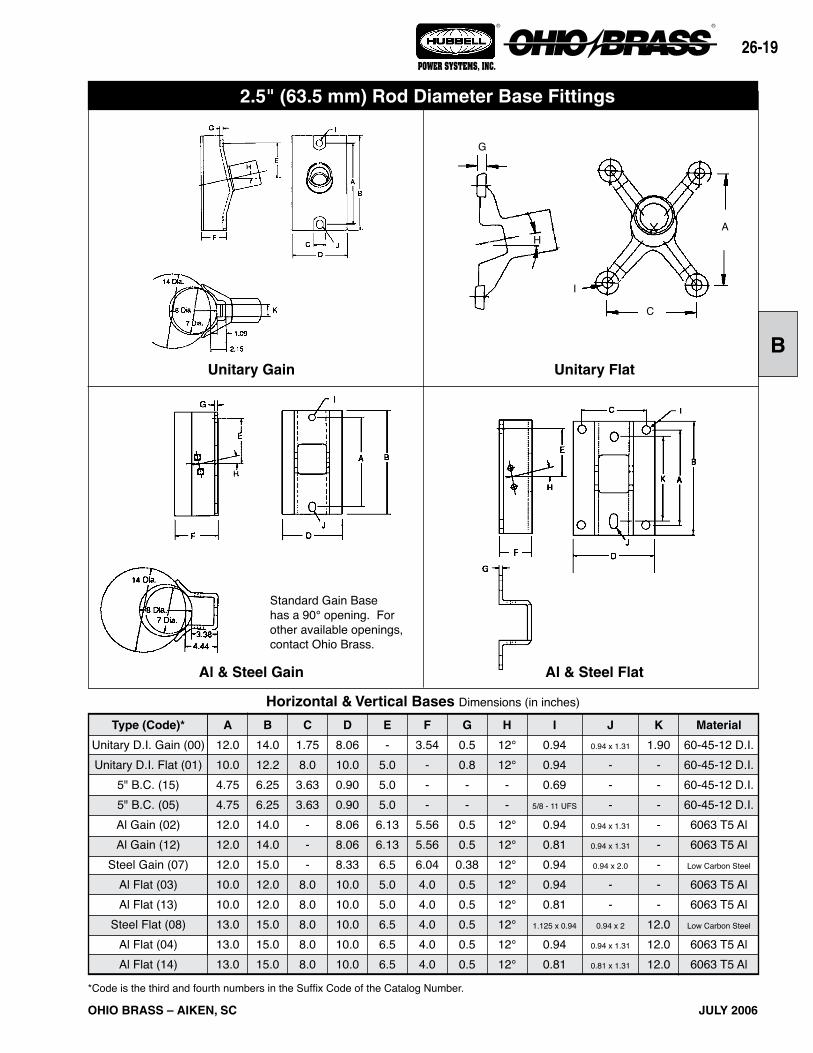
Al & Steel FlatAl & Steel Gain
Horizontal & Vertical Bases Dimensions (in inches)
Type (Code)*
Unitary D.I. Gain (00)Unitary D.I. Flat (01)
5" B.C. (15)5" B.C. (05)Al Gain (02)Al Gain (12)
Steel Gain (07)Al Flat (03)Al Flat (13)
Steel Flat (08)Al Flat (04)Al Flat (14)
A
12.010.04.754.7512.012.012.010.010.013.013.013.0
B
14.012.26.256.2514.014.015.012.012.015.015.015.0
C
1.758.0
3.633.63
---
8.08.08.08.08.0
E
-5.05.05.0
6.136.136.55.05.06.56.56.5
F
3.54---
5.565.566.044.04.04.04.04.0
D
8.0610.00.900.908.068.068.3310.010.010.010.010.0
G
0.50.8--
0.50.5
0.380.50.50.50.50.5
H
12°12°
--
12°12°12°12°12°12°12°12°
I
0.940.940.69
5/8 - 11 UFS
0.940.810.940.940.81
1.125 x 0.94
0.940.81
J
0.94 x 1.31
---
0.94 x 1.31
0.94 x 1.31
0.94 x 2.0
--
0.94 x 2
0.94 x 1.31
0.81 x 1.31
K
1.90--------
12.012.012.0
Material
60-45-12 D.I.60-45-12 D.I.60-45-12 D.I.60-45-12 D.I.6063 T5 Al6063 T5 Al
Low Carbon Steel
6063 T5 Al6063 T5 Al
Low Carbon Steel
6063 T5 Al6063 T5 Al
*Code is the third and fourth numbers in the Suffix Code of the Catalog Number.
Unitary Gain Unitary Flat
2.5" (63.5 mm) Rod Diameter Base Fittings
Standard Gain Base has a 90° opening. For other available openings, contact Ohio Brass.
A
C
G
I
H

OHIO BRASS – AIKEN, SC
26-20
JULY 2006
® ®
POWER SYSTEMS, INC.
Two Hole Blade*12° upsweep post angles
Horizontal Clamptop
Vertical ClamptopPart per ANSI C29.7
5" Bolt CircleLine or Base Fitting
Horizontal & Vertical End Fittings Dimensions (in inches)Material
60-40-18 D.I.60-40-18 D.I.60-40-18 D.l.60-45-12 D.I.60-45-12 D.I.60-40-18 D.I.
Type (Code)*
2 Hole Blade (0)2 Hole Long Blade (9)
H. Clamptop (1)5" B.C. (3)5" B.C. (5)
V. Clamptop (2)
L
0.5R0.5R
----
M
0.44 R0.44R
----
B
4.04.04.0
6.256.254.0
A
5.735.738.244.754.755.88
C
--
3.303.633.633.30
D
0.750.751.120.900.901.12
E
5.257.754.725.05.0
5.37
F
1.251.254.0--
4.0
G
1.504.0---
1.06
H
2.004.5----
I
1.01.0
5/8 - 11 UFS
5/8 - 11 UFS
0.69 x Holes
5/8 - 11 UFS
J
1.441.440.75
---
*Code is the 2nd number in the Suffix Code of the Catalog Number.
2.5" (63.5 mm) Rod Diameter Line Fittings
2 Hole Long Blade64 deg. max.
2 Hole Blade (Std.)40 deg. max.
Transverse Compressing Swing Anglefor Conductor Suspension Clamp
26-2
OHIO BRASS – AIKEN, SC JULY 2006
® ®
POWER SYSTEMS, INC.
B
Application
Line EndEnergized
230 kV
Top - NONEBott. - NONE
345 kV
Top - 2737743001Bott. - NONE
138/161 kV
Top - NONEBott. - NONE
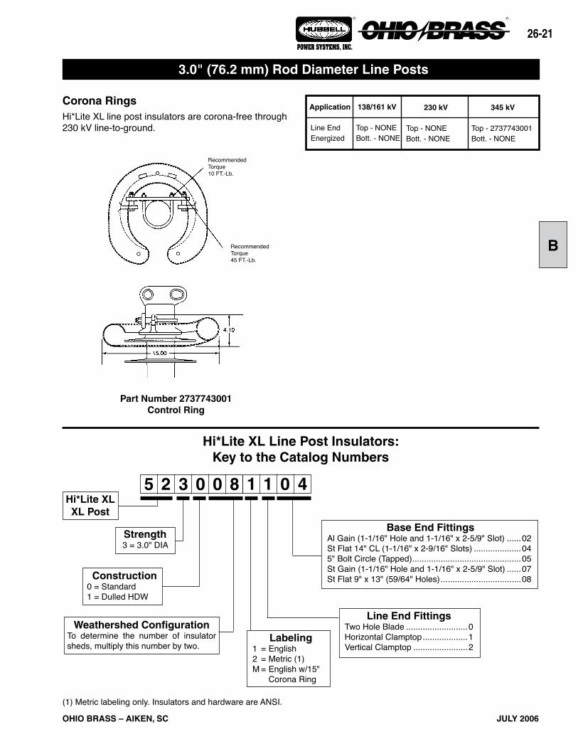
Corona RingsHi*Lite XL line post insulators are corona-free through 230 kV line-to-ground.
3.0" (76.2 mm) Rod Diameter Line Posts
RecommendedTorque45 FT.-Lb.
RecommendedTorque10 FT.-Lb.
Hi*Lite XL Line Post Insulators:Key to the Catalog Numbers
5 2 3 0 1 40 08 1Hi*Lite XLXL Post
Strength3 = 3.0" DIA
Construction0 = Standard1 = Dulled HDW
Weathershed ConfigurationTo determine the number of insulator sheds, multiply this number by two.
Line End FittingsTwo Hole Blade ..........................0Horizontal Clamptop ...................1Vertical Clamptop .......................2
Base End FittingsAl Gain (1-1/16" Hole and 1-1/16" x 2-5/9" Slot) ......02St Flat 14" CL (1-1/16" x 2-9/16" Slots) ....................045" Bolt Circle (Tapped) ..............................................05St Gain (1-1/16" Hole and 1-1/16" x 2-5/9" Slot) ......07St Flat 9" x 13" (59/64" Holes) ..................................08
Part Number 2737743001Control Ring
(1) Metric labeling only. Insulators and hardware are ANSI.
Labeling1 = English2 = Metric (1)M = English w/15" Corona Ring

OHIO BRASS – AIKEN, SC
26-22
JULY 2006
® ®
POWER SYSTEMS, INC.
69 345230138 161115
Selection GuideTypical
Line Voltage, kV
Notes: (1) Tests in accordance with ANSI C29.1-1982. Electrical values are without corona ring. (2) RCL is the maximum continuous load at which the post should be applied. For voltages above 230 kV refer to Page 26-21 for Corona Rings. Electrical values are shown for insulators without rings. For electricals with rings, contact Ohio Brass.
“X”LengthInches(mm)38.8(986)43.8
(1113)49.0
(1245)54.8
(1392)59.3
(1506)64.5
(1638)69.5
(1765)74.7
(1897)79.9
(2029)85.0
(2159)90.2
(2291)95.2
(2418)100.4(2550)105.5(2680)110.7(2812)115.9(2944)
Catalog #with
Flat Base& Two Hole
Blade
5230051004
5230061004
5230071004
5230081004
5230091004
5230101004
5230111004
5230121004
5230131004
5230141004
5230151004
5230161004
5230171004
5230181004
5230191004
5230201004
No.of
Sheds
10
12
14
16
18
20
22
24
26
28
30
32
34
36
38
40
Dry ArcDistanceinches(mm)
29(737)
34(864)
39(991)
45(1143)
50(1270)
55(1397)
60(1524)
66(1676)
71(1803)
76(1930)
82(2083)
87(2210)
92(2337)
98(2489)
103(2616)
108(2743)
LeakageDistanceinches(mm)
77(1956)
93(2362)
108(2743)
124(3150)
140(3556)
156(3962)
171(4343)
187(4750)
203(5156)
218(5537)
234(5944)
250(6350)
265(6731)
281(7137)
297(7544)
313(7950)
(1) 60 Flashover
ANSI
(1) CriticalFlashover
ANSI
NetWeightpounds
(kg)90
(40.8)95
(43.1)100
(40.9)106
(48.1)110
(49.9)115
(52.2)120
(54.4)125
(56.7)130
(58.9)135
(61.2)141
(63.9)146
(66.2)151
(68.5)156
(70.8)161
(73.1)166
(75.3)
(2)RCLpounds
(kN)4405(19.6)3780(16.8)3295(14.7)2920(13.0)2620(11.7)2380(10.6)2185(9.7)2015(9.0)1865(8.3)1740(7.7)1630(7.2)1535(6.8)1450(6.5)1370(6.1)1300(5.8)1240(5.5)
Dry-kV
295
345
395
445
495
545
590
640
685
735
780
825
870
915
960
1000
Wet-kV
250
295
335
380
420
465
505
550
590
640
670
710
755
795
835
875
Pos-kV
445
530
615
695
780
865
950
1035
1120
1205
1290
1370
1455
1540
1625
1710
Neg-kV
540
620
705
790
870
955
1035
1120
1200
1285
1365
1445
1530
1615
1695
1780
3.0" (76.2mm) Rod Diameter Horizontal Line Posts
See Page 26-25
Line & Base Detail see Pages 26-24 & 26-25
Clamptop:Maximum Design Tension = 2,500 lb (11.1 kN)
Two-Hole Blade:Maximum Design Tension = 12,500 lb. (55.6 kN)
Horizontal Clamptop End FittingIncreases the “X” dimension
by 1"

26-2
OHIO BRASS – AIKEN, SC JULY 2006
® ®
POWER SYSTEMS, INC.
B
69
NetWeightpounds
(kg)54
(24.5)59
(26.8)64
(29.1)69
(31.4)74
(33.6)79
(35.9)
Notes: (1) Tests in accordance with ANSI C29.1-1982. (2) RCL is the maximum cantilever continuous load at which the post should be applied.
115 138 161
Selection GuideTypical
Line Voltage, kV
Catalog #with 5" Bolt
Circle & Vert. Clamptop
5230051205
5230061205
5230071205
5230081205
5230091205
5230101205
“X”LengthInches(mm)38.0(965)43.2
(1097)48.5
(1219)53.8
(1367)59.2
(1504)64.5
(1638)
Dry ArcDistanceinches(mm)
29(737)
34(864)
39(991)
45(1143)
50(1270)
55(1397)
LeakageDistanceinches(mm)
77(1956)
93(2362)
108(2743)
124(3150)
140(3556)
156(3962)
(1) 60 Flashover
ANSI
(1) CriticalFlashover
ANSIWet-kV
250
295
335
380
420
465
Pos-kV
445
530
615
695
780
865
Neg-kV
540
620
705
785
870
950
(2)RCLpounds
(kN)2500(11.1)2500(11.1)2500(11.1)2500(11.1)2500(11.1)2335(10.4)
No.of
Sheds
10
12
14
16
18
20
Dry-kV
295
345
395
445
495
545
Line & Base Fitting Detail see pages 26-24 & 26-25
Maximum Design Tension2,500 lb (11.1 kN)
3.0" (76.2 mm) Rod Diameter Vertical Line Posts

OHIO BRASS – AIKEN, SC
26-2
JULY 2006
® ®
POWER SYSTEMS, INC.
Horizontal & Vertical Bases Dimensions (in inches)Type (Code)*
5" B.C. (05)Al Gain (02)
Steel Gain (07)Steel Flat (08)Steel Flat (04)
A
6.3614.014.013.014.0
B
5.917.017.015.017.0
C
4.37--
9.0-
E
5.07.757.756.5
7.75
F
-5.9497.034.124.12
D
1.28.0799.6511.010.0
G
-0.530.50.50.5
H
-14°14°14°14°
I
5/8 - 11 UFS
1.061.06
0.938-
J
-
1.06 x 2.56
1.06 x 2.56
-
1.06 x 2.56
Material
60-40-18 D.I.6063 T5 Al
Low Carbon Steel
Low Carbon Steel
Low Carbon Steel
*Code is the 2nd number in the Suffix Code of the Catalog Number.
Steel FlatSteel Gain
Hi*Lite XL 3.0" Rod Dia. Base Fittings
Aluminum Gain 5" Bolt Circle
26-2
OHIO BRASS – AIKEN, SC JULY 2006
® ®
POWER SYSTEMS, INC.
B
*Code is the 2nd digit in the Suffix Code of the Catalog Number.
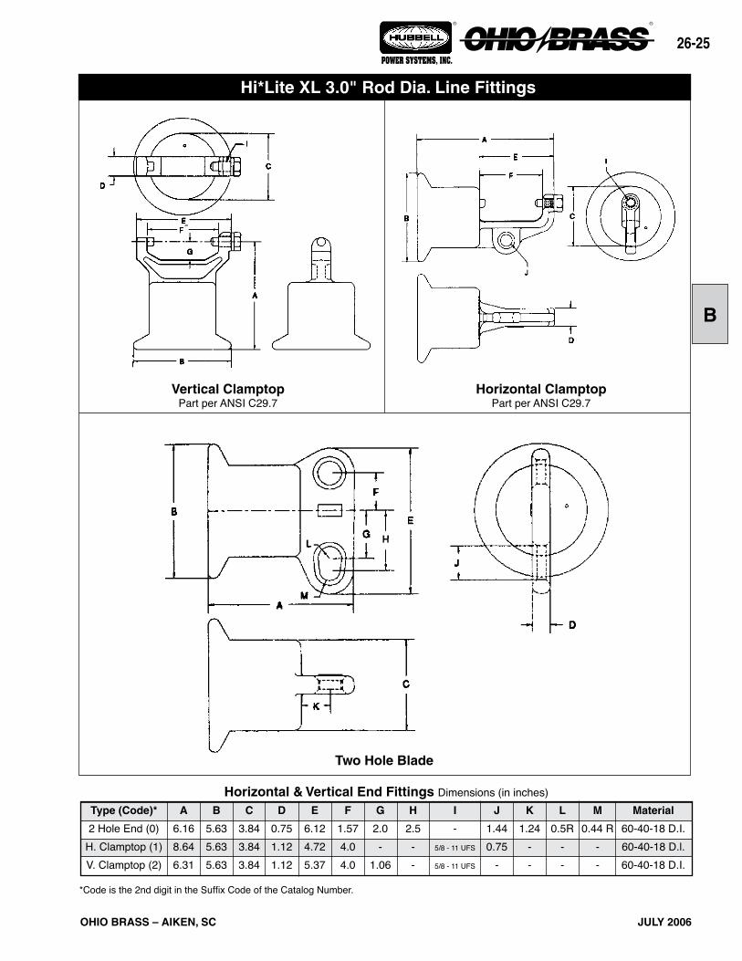
Vertical ClamptopPart per ANSI C29.7
Horizontal ClamptopPart per ANSI C29.7
Material
60-40-18 D.I.60-40-18 D.l.60-40-18 D.I.
B
5.635.635.63
A
6.168.646.31
Type (Code)*
2 Hole End (0)H. Clamptop (1)V. Clamptop (2)
C
3.843.843.84
D
0.751.121.12
E
6.124.725.37
F
1.574.04.0
G
2.0-
1.06
H
2.5--
I
-5/8 - 11 UFS
5/8 - 11 UFS
J
1.440.75
-
K
1.24--
L
0.5R--
M
0.44 R--
Horizontal & Vertical End Fittings Dimensions (in inches)
Two Hole Blade
Hi*Lite XL 3.0" Rod Dia. Line Fittings
OHIO BRASS – AIKEN, SC
26-26
JULY 2006
® ®
POWER SYSTEMS, INC.
Figure 2 Figure 4
Figure 1 Figure 3
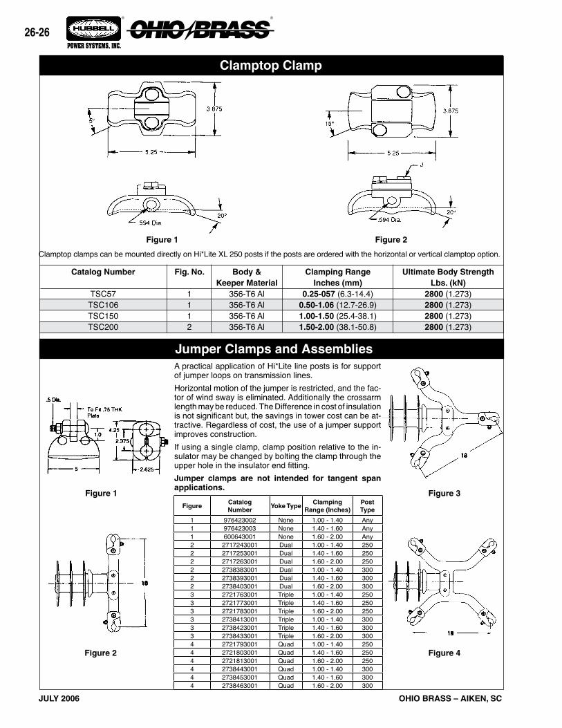
Clamptop Clamp
Jumper Clamps and AssembliesA practical application of Hi*Lite line posts is for support of jumper loops on transmission lines.Horizontal motion of the jumper is restricted, and the fac-tor of wind sway is eliminated. Additionally the crossarm length may be reduced. The Difference in cost of insulation is not significant but, the savings in tower cost can be at-tractive. Regardless of cost, the use of a jumper support improves construction.If using a single clamp, clamp position relative to the in-sulator may be changed by bolting the clamp through the upper hole in the insulator end fitting.Jumper clamps are not intended for tangent span applications.
Clamptop clamps can be mounted directly on Hi*Lite XL 250 posts if the posts are ordered with the horizontal or vertical clamptop option.
Figure 1 Figure 2
FigureCatalog Number
Yoke TypeClamping
Range (Inches)Post Type
1 976423002 None 1.00 - 1.40 Any1 976423003 None 1.40 - 1.60 Any1 600643001 None 1.60 - 2.00 Any2 2717243001 Dual 1.00 - 1.40 2502 2717253001 Dual 1.40 - 1.60 2502 2717263001 Dual 1.60 - 2.00 2502 2738383001 Dual 1.00 - 1.40 3002 2738393001 Dual 1.40 - 1.60 3002 2738403001 Dual 1.60 - 2.00 3003 2721763001 Triple 1.00 - 1.40 2503 2721773001 Triple 1.40 - 1.60 2503 2721783001 Triple 1.60 - 2.00 2503 2738413001 Triple 1.00 - 1.40 3003 2738423001 Triple 1.40 - 1.60 3003 2738433001 Triple 1.60 - 2.00 3004 2721793001 Quad 1.00 - 1.40 2504 2721803001 Quad 1.40 - 1.60 2504 2721813001 Quad 1.60 - 2.00 2504 2738443001 Quad 1.00 - 1.40 3004 2738453001 Quad 1.40 - 1.60 3004 2738463001 Quad 1.60 - 2.00 300
Catalog Number
TSC57TSC106TSC150TSC200
Fig. No.
1112
Body &Keeper Material
356-T6 Al356-T6 Al356-T6 Al356-T6 Al
Clamping RangeInches (mm)
0.25-057 (6.3-14.4)0.50-1.06 (12.7-26.9)1.00-1.50 (25.4-38.1)1.50-2.00 (38.1-50.8)
Ultimate Body StrengthLbs. (kN)
2800 (1.273)2800 (1.273)2800 (1.273)2800 (1.273)
26-2
OHIO BRASS – AIKEN, SC JULY 2006
® ®
POWER SYSTEMS, INC.
C
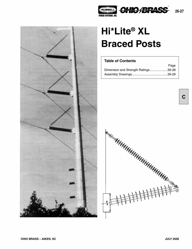
Hi*Lite® XL Braced Posts
Table of ContentsPage
Dimension and Strength Ratings .................... 26-28Assembly Drawings ........................................ 26-29

OHIO BRASS – AIKEN, SC
26-2
JULY 2006
® ®
POWER SYSTEMS, INC.
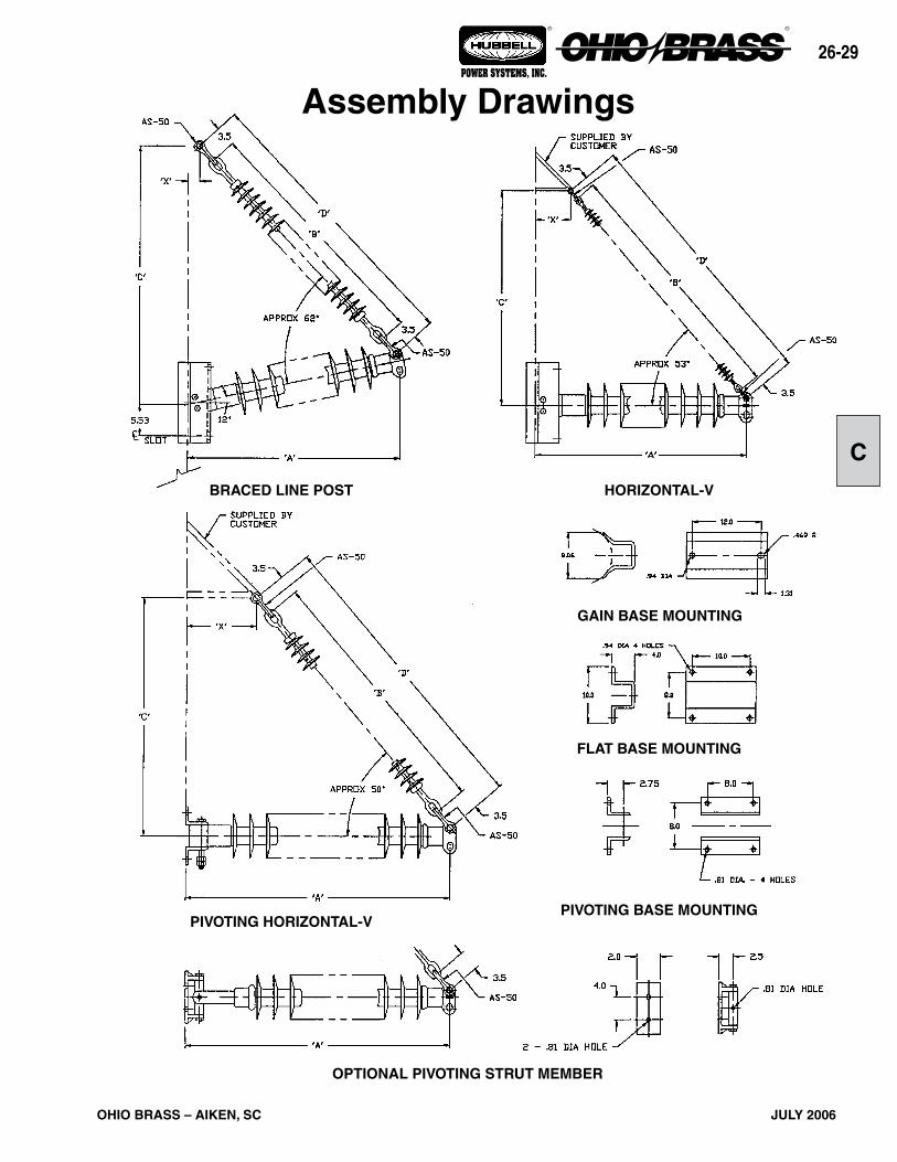
Catalog number covers complete assembly including insulator and hardware as illustrated.
The need to minimize the tower size and visual impact of transmission lines has prompted increased interest in braced line posts, horizontal-V, and pivoting V assemblies. These insulating structures offer vastly improved vertical load capabilities over conventional lines posts while retaining the advantages of a fixed conductor position.A braced line post uses a conventional line post with a sus-pension string tied to the tower face with a link. A horizontal-V replaces the link with a fixed offset extending from the tower face adding a stabilizing force to the assembly. Both these assemblies are available with flat or gain bases.
A pivoting horizontal-V assembly utilizes a line post insulator fastened to the structure with a hinged base. Alternatively, the base may be replaced with a universal joint.These assemblies are available for voltages up to and including 345 kV with a wide variety of hardware to meet the needs of your application. The figures illustrated depict typical arrangements which provide an economical means of with-standing unusual loads. For more information on these and numerous other variations of line post assemblies, contact your Ohio Brass representative.
DIMENSIONS ANDSTRENGTH RATINGS
Suspension511010511211511013511014511018511219
BRACED LINE POST ASSEMBLYTypicalSystem
kV115/138115/138
161 161
230 *230 *
Cat #Gain Base
234220234222234224234226234228234230
Cat #Flat
Base234221234223234225234227234229234231
Post522008522009522010522011522014522015
Component Insulators
Vertical112801128011280112801128011280
Tension750075007500750075007500
Longitudinal17301550141012801020 960
Dimensions (in.) Maximum Loadings** (lb.)
A53.758.864.169.485.090.3
B72.881.991.197.2
121.6130.7
C74.083.091.096.0118.0127.0
X222222
D79.888.998.1
104.2128.6137.7
Compres-sion
125001250012500125001181010470
Suspension511007511008511009511010511013511014
HORIZONTAL V ASSEMBLYTypicalSystem
kV115/138115/138
161 161
230 *230 *
Cat #Gain Base
234232234234234236234238234240234242
Cat #Flat
Base234233234235234237234239234241234243
Post522008522009522010522011522014522015
Component Insulators
Vertical998099809980998099809980
Tension750075007500750075007500
Longitudinal16801510137012501000 930
Dimensions (in.) Maximum Loadings** (lb.)
A54.960.165.570.986.992.3
B54.660.766.772.891.197.2
C51.056.061.066.080.085.0
X182022242830
D 61.6 67.7 73.7 79.8 98.1104.2
Compres-sion
125001250012500125001250012500
Suspension511007511008511009511010511013511014
PIVOTING HORIZONTAL V ASSEMBLYTypicalSystem
kV115/138115/138
161 161
230 *230 *
Cat #Gain Base
——————
Cat #Flat
Base234244234245234246234247234248234249
Post522008522009522010522011522014522015
Component Insulators
Vertical998099809980998099809980
Tension750075007500750075007500
Longitudinal——————
Dimensions (in.) Maximum Loadings** (lb.)
A55.260.465.871.287.292.6
B54.660.766.772.891.197.2
C51.056.061.066.080.085.0
X182022242830
D 61.6 67.7 73.7 79.8 98.1104.2
Compres-sion
125001250012500125001250012500
Contact your Ohio Brass representative for designs utilizing the optional pivoting strut member.* Corona rings are required for 230 kV and above.** Maximum loads are for single loads in the specified direction.
Hi*Lite® XL Assemblies
26-2
OHIO BRASS – AIKEN, SC JULY 2006
® ®
POWER SYSTEMS, INC.
C
OPTIONAL PIVOTING STRUT MEMBER
FLAT BASE MOUNTING
PIVOTING BASE MOUNTINGPIVOTING HORIZONTAL-V
BRACED LINE POST HORIZONTAL-V
GAIN BASE MOUNTING
Assembly Drawings

OHIO BRASS – AIKEN, SC
26-0
JULY 2006
® ®
POWER SYSTEMS, INC.
26-
OHIO BRASS – AIKEN, SC JULY 2006
® ®
POWER SYSTEMS, INC.
D
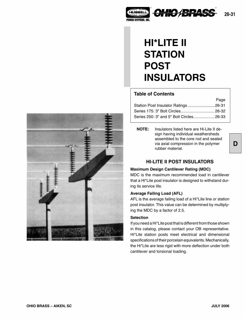
HI-LITE II POST INSULATORS
Maximum Design Cantilever Rating (MDC)MDC is the maximum recommended load in cantilever that a Hi*Lite post insulator is designed to withstand dur-ing its service life.
Average Failing Load (AFL)AFL is the average failing load of a Hi*Lite line or station post insulator. This value can be determined by multiply-ing the MDC by a factor of 2.5.
SelectionIf you need a Hi*Lite post that is different from those shown in this catalog, please contact your OB representative. Hi*Lite station posts meet electrical and dimensional specifications of their porcelain equivalents. Mechanically, the Hi*Lite are less rigid with more deflection under both cantilever and torsional loading.
HI*LITE IISTATIONPOSTINSULATORS
Table of ContentsPage
Station Post Insulator Ratings ........................ 26-31Series 175: 3" Bolt Circles .............................. 26-32Series 250: 3" and 5" Bolt Circles ................... 26-33
NOTE: Insulators listed here are Hi-Lite II de-sign having individual weathersheds assembled to the core rod and sealed via axial compression in the polymer rubber material.
OHIO BRASS – AIKEN, SC
26-2
JULY 2006
® ®
POWER SYSTEMS, INC.
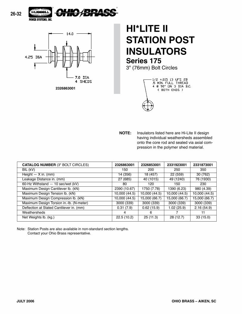
Note: Station Posts are also available in non-standard section lengths. Contact your Ohio Brass representative.
CATALOG NUMBER (3" BOLT CIRCLES)BIL (kV)Height — X in. (mm)Leakage Distance in. (mm)60-Hz Withstand — 10 sec/wet (kV)Maximum Design Cantilever lb. (kN)Maximum Design Tension lb. (kN)Maximum Design Compression lb. (kN)Maximum Design Torsion in.-lb. (N-meter)Deflection at Stated Cantilever in. (mm)WeathershedsNet Weights lb. (kg.)
HI*LITE II STATION POST INSULATORSSeries 1753" (76mm) Bolt Circles
NOTE: Insulators listed here are Hi-Lite II design having individual weathersheds assembled onto the core rod and sealed via axial com-pression in the polymer shed material.
2326863001
2326863001150
14 (356)27 (685)
802390 (10.67)10,000 (44.5)10,000 (44.5)3000 (339)0.31 (7.9)
422.5 (10.2)
2326853001200
18 (457)40 (1015)
1201750 (7.78)
10,000 (44.5)15,000 (66.7)3000 (339)0.62 (15.9)
625 (11.3)
2331923001250
22 (559)49 (1240)
1501390 (6.23)
10,000 (44.5)15,000 (66.7)3000 (339)1.02 (25.9)
728 (12.7)
2331873001350
30 (762)76 (1930)
230980 (4.39)
10,000 (44.5)15,000 (66.7)3000 (339)2.16 (54.9)
1133 (15.0)

26-
OHIO BRASS – AIKEN, SC JULY 2006
® ®
POWER SYSTEMS, INC.
D
Notes: 1. Station Posts are also available in non-standard section lengths. Contact Ohio Brass. 2. At 230 kV, corona ring 2721273001 may be required. 3. For through holes, specify code 3002.
CATALOG NUMBER (5" BOLT CIRCLES)BIL (kV)Height — X in. (mm)Leakage Distance in. (mm)60-Hz Withstand — 10 sec/wet (kV)Maximum Design Cantilever lb. (kN)Maximum Design Tension lb. (kN)Maximum Design Compression lb. (kN)Maximum Design Torsion in.-lb. (N-meter)Deflection at Stated Cantilever in. (mm)WeathershedsNet Weights lb. (kg.)
2323753001900
80 (2032)204 (5180)
560990 (4.45)
30,000 (133) 35,000 (156)9,000 (66.7)13.50 (343)
2272 (32.7)
CATALOG NUMBER (3" BOLT CIRCLES)BIL (kV)Height — X in. (mm)Leakage Distance in. (mm)60-Hz Withstand — 10 sec/wet (kV)Maximum Design Cantilever lb. (kN)Maximum Design Tension lb. (kN)Maximum Design Compression lb. (kN)Maximum Design Torsion in.-lb. (N-meter)Deflection at Stated Cantilever in. (mm)WeathershedsNet Weights lb. (kg.)
2323013001350
30 (762)63 (1570)
1901400 (6.23)
30,000 (133)50,000 (222)9,000 (1000)
1.0 (25)7
30 (13.6)
2323003001650
54 (1372)128 (3250)
380770 (3.42)
30,000 (133)50,000 (222)9,000 (1000)
3.4 (86)14
51 (23)
2323093001750
62 (1575)148 (3760)
430670 (2.98)
30,000 (133)50,000 (222)9,000 (1000)
4.5 (114)16
54 (24.5)
2321993001550
45 (1143)102 (2590)
300930 (4.14)
30,000 (133)50,000 (222)9,000 (1000)
2.3 (58)11
42 (19)
2323363001350
30 (762)64 (1626)
1902900 (12.90)30,000 (133)50,000 (222)9000 (1000)
1.77 (458
30 (13.6)
2323373001550
45 (1143)109 (2770)
3201850 (8.23)
30,000 (133)50,000 (222)9000 (1000)4.13 (105)
1242 (19)
2323383001650
54 (1372)130 (3300)
3801520 (6.76)
30,000 (133)50,000 (222)9000 (1000)6.00 (152)
1451 (23)
2323393001750
62 (1575)156 (3960)
4501310 (5.83)
30,000 (133)50,000 (222)9000 (1000)8.00 (203)
1754 (24.5)
HI*LITE IISTATION POSTINSULATORSSeries 2505" (127mm) Bolt Circles
2323373001
2321993001

OHIO BRASS – AIKEN, SC
26-
JULY 2006
® ®
POWER SYSTEMS, INC.

26-
OHIO BRASS – AIKEN, SC JULY 2006
® ®
POWER SYSTEMS, INC.
E
Sample Polymer Specification
Purpose: To ensure a suitable service life of polymer insulating materials.I. Material Design Tests - The following must be performed to certify a material for use in production.
1. Tracking test: Performed on a sample of material inclined at 30° and electrodes positioned 35mm apart. Samples are sprayed with a conductive solution (400Ωcm) and energized at 10kV. The cycle is repeated every 90 seconds. The sample pass-es if there is:
1. No carbonization or tracking. 2. No erosion through sample. 3. No leakage current flow at the end of 90 seconds. The sample must withstand 15,000 test cycles.2. Ultraviolet Test: Samples of the rubber must be tested in a QUV tester or equiva-
lent cyclic weatherometer. The samples are exposed to high ultraviolet radiation and high humidity without cracking, checking or becoming hydrophilic.
The sample is judged to have passed this test if it exceeds 8,000 hours of exposure without damage.
3. Corona Cutting: Samples 5 cm by 7 cm are subjected to mechanical stress of 300,000 µstrain by bending samples around a grounded electrode. A needle-like electrode is placed 1 mm from the surface of the sample and energized at 12 kV in a controlled humidity chamber.
The sample is judged to have passed this test if there is no splitting or cutting. Samples must pass 1,000 hours of exposure to this test.
4. Oxidative Stability: Samples of the polymer compound are tested using differ-ential scanning calorimetry. Samples are heated rapidly in a nitrogen atmosphere to the test temperature of 200°C. The atmosphere is then changed to air and the temperature is maintained until the antioxidant is consumed, as measured by an exothermic chemical reaction. The time to this reaction must exceed 300 minutes.
5. Tear Strength: Rubber test slabs are prepared in accordance with ASTM Stan-dards and are tested to determine tear strength of the material. The minimum ac-ceptable tear strength is 150 lb./in.
II. Other Requirements- The manufacturer must supply upon request a listing of routine tests performed to
ensure production compliance with design tests.

27-
OHIO BRASS – WADSWORTH, OHIO NOVEMBER 2006
® ®
POWER SYSTEMS, INC.
Table of ContentsPage
Design............................................................................. 2Rod.................................................................................. 2End.Fittings..................................................................... 2Weathersheds................................................................. 2Interface.......................................................................... 2Leakage.Distance............................................................ 2Washability...................................................................... 2Mechanical.Ratings......................................................... 2Lengths.Available............................................................ 2Product.Updates.............................................................. 2Packaging........................................................................ 2Corona.Performance....................................................... 3Key.to.the.Catalog.Numbers........................................... 4End.Fitting.Detail............................................................. 4Hi*Lite.XL.120kN.SML.Data............................................ 5Hi*Lite.XL.125kN.SML.Data............................................ 6Hi*Lite.XL.160kN.SML.Data............................................ 7Hi*Lite.XL.210kN.SML.Data............................................ 8
Hi*Lite® XLSuspension Insulators
Printed.in.USA
ANSI C29.12/IEC 1109 TESTED
Warranty - MaterialHubbell Power Systems, Inc. warrants all products sold by it to be merchantable (as such term is defined in the Uniform Commercial Code) and to be free from defects in material and workmanship. Buyer must notify the Company promptly of any claim under this warranty. The Buyer's exclusive remedy for breach of this warranty shall be the repair or replacement, F.O.B. factory, at the Company's option, of any product defective under the warranty which is returned to the Company within one year from the date of shipment. NO OTHER WARRANTY, WHETHER EXPRESS OR ARISING BY OPERATION OF LAW, COURSE OF DEALING, USAGE OF TRADE OR OTHERWISE IMPLIED, SHALL EXIST IN CONNECTION WITH THE COMPANY'S PRODUCTS OR ANY SALE OR USE THEREOF. The Company shall in no event be liable for any loss of profits or any consequential or special damages incurred by Buyer. The Company's warranty shall run only to the first Buyer of a product from the Company, from the Company's distributor, or from an original equipment manufacturer reselling the Company's product, and is
non-assignable and non-transferable and shall be of no force and effect if asserted by any per-son other than such first Buyer. This warranty applies only to the use of the product as intended by Seller and does not cover any misapplication or misuse of said product.
Warranty - ApplicationHubbell Power Systems, Inc. does not warrant the accuracy of and results from product or system performance recommendations resulting from any engineering analysis or study. This applies regardless of whether a charge is made for the recommendation, or if it is provided free of charge.
Responsibility for selection of the proper product or application rests solely with the purchaser. In the event of errors or inaccuracies determined to be caused by Hubbell Power Systems, Inc., its liability will be limited to the re-performance of any such analysis or study.
©Copyright.2006..Hubbell/Ohio.Brass..•..8711.Wadsworth.Road..•..Wadsworth,.OH.44281NOTE: Because Hubbell has a policy of continuous product improvement, we reserve the right to change design and specifications without notice.
27

OHIO BRASS – WADSWORTH, OHIO
27-2
NOVEMBER 2006
® ®
POWER SYSTEMS, INC.
Hi*Lite® XL InsulatorsHi*Lite.XL.suspension.insulators.in.this.publication.embody.the.latest.features.available.in.polymer.insulator.design.and.manufacture.From.the.early.prototypes.in.1971,.through.full.scale.introduction.in.1976,.and.through.the.succeeding.years,.Hi*Lite.insulators.have.featured.conservative.design.and.high-quality.manufacture.Today’s.Hi*Lite.insulators.will.add.to.the.over.1,000,000.Hi*Lite.trans-mission.insulators.already.in.service.worldwide.DesignThe.structural.design.of.the.Hi*Lite.XL.consists.of.these.basic.parts:Rod - Hi*Lite insulator fiberglass rod is produced from the highest quality.materials..Strands.are.aligned.for.maximum.tensile.strength..The rod is more than 50 percent glass fibers in cross section.End Fittings - End fittings are steel or ductile iron. They are crimped directly.to.the.rod.by.a.special.process.originated.by.Ohio.Brass,.and.later.adopted.by.many.other.producers..The.crimp.develops.a.high.percentage.of.the.rod’s.inherent.tensile.strength..It.requires.no.inter-movement.of.the.parts.to.achieve.high.strength,.nor.does.it.introduce.potting.compounds.or.adhesives.
Leakage DistanceHi*Lite.XL.insulators.feature.high.leakage.distance.for.maximum.resistance to contamination and leakage currents. Specific leakage distance.(leakage.divided.by.dry.arcing.distance).is.higher.than.that.of.porcelain..Hi*Lite.XL.insulators.are.offered.in.standard.uniform.weathershed configuration and alternating (major/minor) weather-shed configuration for applications requiring increased specified leakage.distances.
WashabilityHi*Lite XL insulators listed in this catalog are suitable for flood wash-ing.up.to.1,380.kPA.(200.psi).at.the.ground.pump.level.at.a.distance.not.less.than.4.6.meters.(15.ft.).The.design.incorporates.positive,.labyrinth.seals.to.ensure.long-term.security.against.water.entry..Conventional.dry-particle,.air-pressure.cleaning.methods.may.be.employed.High.Pressure.wash.designs.are.also.available..Washing.is.permis-sible.for.up.to.6,900.kPA.(1,000.psi).ground.pump.pressure.at.a.distance.no.less.than.1.8.meters.(6.feet).Cleaning guidelines (Ohio Brass publication #EU1272-H for flood and.#EU1273-H.for.high.pressure.wash).are.available.from.your.representative.Mechanical RatingsHi*Lite.XL.suspension.insulators.are.rated.and.tested.in.accordance.with IEC 1109-1992 and ANSI C29.12-1997. Certified test reports in detail.are.available.SML.ratings.are.120.kN,.160.kN.and.210.kN.for.insulators.furnished.with IEC fittings. For insulators furnished with ANSI fittings, SML ratings.available.are.111.kN.(25K.lbs.),.133.kN.(30K.lbs.),.160.kN.(36K.lbs.).and.222.kN.(50K.lbs.).RTL.ratings.are.consistent.with.the.IEC.and.ANSI.standard..Actual.factory.routine.tests.are.conducted.at.loads.equal.to.or.greater.than.the.RTL.rating.Markings.for.XL.insulator.design.are.permanently.embossed.into.the.ground.end.corona.shielding.rings.(CSR)..Markings.include.SML.and.RTL, part number, assembly date code, and Ohio Brass identifica-tion..These.marks.are.consistent.with.the.IEC.and.ANSI.standard.Lengths AvailableHi*Lite.XL.suspension.insulators.are.available.in.lengths.appropriate.for.69.kV.through.765.kV..Longer.lengths.can.be.produced.for.special.projects. Intermediate lengths (utilizing an additional 2 sheds) are also.available.(those.that.fall.in.between.the.catalog.numbers.listed.in.the.tables)..Length.increments.are.approximately.76.mm.(3.inches).TestingThe.Hi*Lite.XL.suspension.insulator.has.been.successfully."Design".tested.to.IEC.1109.at.an.independent.laboratory..In.addition,.the.Hi*Lite.XL.suspension.insulator.has.successfully.completed.the.5,000.hour.accelerated.aging.test.detailed.in.Annex.C.of.IEC.1109..A.certi-fied test report is available by contacting your Ohio Brass representa-tive.and.requesting.bulletin.EU1348-H.Since.the.ANSI."Prototype".and.IEC."Design".testing.requirements.are.virtually.identical,.the."Design".test.report.per.IEC.1109.can.serve.as verification of compliance to ANSI.PackagingHi*Lite.suspension.insulators.are.packaged.in.appropriate.quanti-ties.in.wooden.crates.111.7.cm.(44.inches).wide.with.the.length.of.the.crate.determined.by.the.length.of.the.insulator..The.height.of.the.crate.is.normally.less.than.114.3.cm.(45.inches)..The.gross.weight.will.not.exceed.909.kg.(2,000.lbs.)..Crates.are.available.for.both.domestic.and.export.transportation.
Uniform Profile Alternating Profile Export.Crate
Weathersheds - Weathersheds are high pressure injection molded by.Ohio.Brass,.from.the.proprietary.compound.ESP™..Housings.manufactured.with.ESP.silicone.alloy.rubber.exhibit.long-term.hydro-phobicity,.high.mechanical.strength,.excellent.corona.resistance.and.low.permeability.to.moisture.Interface -.Hi*Lite.insulators.use.Ohio.Brass’.patented.live.silicone.interface.(U.S..Patent.No..3,898,372)..This.feature.prevents.intrusion.of.moisture.and.contaminating.elements..In.the.unlikely.event.the.ex-terior.seal.is.damaged,.redundant.o-ring.seals.within.the.live.silicone.interface.will.prohibit.the.lengthwise.migration.of.intrusive.elements.between.shed.and.rod.
ROD
SILICONECOMPOUND
O-RINGS
27-
OHIO BRASS – WADSWORTH, OHIO NOVEMBER 2006
® ®
POWER SYSTEMS, INC.
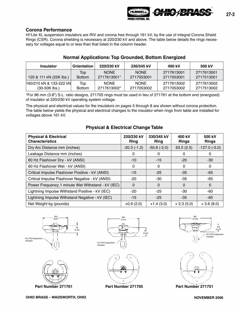
Normal Applications: Top Grounded, Bottom Energized
500 kV
2717613001271751300127176130022717513002
400 kV
2717613001271705300127176130022717053002
330/345 kV
NONE2717053001
NONE2717053002
220/230 kV
NONE2717613001*
NONE2717613002*
Orientation
TopBottom
TopBottom
Insulator
120.&.111.kN.(25K.lbs.)160/210.kN.&.133-222.kN.
(30-50K.lbs.)*For 96 mm (3.8") S.L. ratio designs, 271705 rings must be used in lieu of 271761 at the bottom end (energized) of.insulator.at.220/230.kV.operating.system.voltage.The.physical.and.electrical.values.for.the.insulators.on.pages.5.through.8.are.shown.without.corona.protection..The.table.below.yields.the.physical.and.electrical.changes.to.the.insulator.when.rings.from.table.are.installed.for.voltages.above.161.kV.
Part Number 271761 Part Number 271705 Part Number 271751
Corona PerformanceHi*Lite.XL.suspension.insulators.are.RIV.and.corona.free.through.161.kV,.by.the.use.of.integral.Corona.Shield.Rings.(CSR)..Corona.shielding.is.necessary.at.220/230.kV.and.above..The.table.below.details.the.rings.neces-sary.for.voltages.equal.to.or.less.than.that.listed.in.the.column.header.
Physical & Electrical Change Table
500 kVRings
-127.0.(-5.0)0
-300
-65-650
-60-65
+.3.6.(8.0)
400 kVRings
63.5.(2.5)0
-200
-35-350
-30-35
+.2.3.(5.0)
330/345 kVRing
-50.8.(-2.0)0
-150
-25-300
-25-25
+1.4.(3.0)
220/230 kVRing
-20.3.(-1.2)0
-100
-15-200
-20-15
+0.9.(2.0)
Physical & ElectricalCharacteristics
Dry.Arc.Distance.mm.(inches)Leakage.Distance.mm.(inches)60 Hz Flashover Dry - kV (ANSI)60 Hz Flashover Wet - kV (ANSI)Critical.Impulse.Flashover.Positive.-.kV.(ANSI)Critical.Impulse.Flashover.Negative.-.kV.(ANSI)Power.Frequency.1.minute.Wet.Withstand.-.kV.(IEC)Lightning.Impulse.Withstand.Positive.-.kV.(IEC)Lightning.Impulse.Withstand.Negative.-.kV.(IEC)Net.Weight.kg.(pounds)
HI-LITE.Suspension.Insulator
104(4.10)
381(15.00)
HI-LITE.Suspension.Insulator
87(3.44)
305(12.0)
HI-LITE.Suspension.Insulator
62(2.44)
203(8.0)

OHIO BRASS – WADSWORTH, OHIO
27-
NOVEMBER 2006
® ®
POWER SYSTEMS, INC.
D 1 0 0 2 70 08 A
GG = Line End FittingsChain.Eye.............................................00.ANSI.Ball..............................................01.Y-Clevis................................................02.ANSI.Straight.Clevis.............................04.IEC.Ball.............................................. 07*IEC.Straight.Clevis...............................08.*For.160.kN,.20.mm.ball,.use.“09”.code.
F = Ground End FittingsChain.Eye...............................................0Y-Clevis..................................................2ANSI.Socket...........................................3ANSI.Straight.Clevis...............................4IEC.Straight.Clevis.................................8IEC.Socket.............................................A
E = Labeling1.=.English2.=.Metric
AA = Hi*Lite XL51.=.63.mm.(2.5".S.L.)A1.=.73.mm.(2.9".S.L.)D1.=.83.mm.(3.3".S.L.)G1.=.96.mm.(3.8".S.L)S.L. = Specified Leak (approx. leak/dry.arc)+These.codes.apply.to.our.ESP.silicone.alloy.compound..For.other.polymer.materials.contact.Ohio.Brass.
Hi*Lite XL Suspension Insulators:Key to the Catalog Numbers
B = Strength0.=.120.kN.SML1.=.111.kN.(25K.lbs.).SML2.=.160.kN.(36K.lbs.),.133.kN.(30K.lbs.).SML3.=.210.kN,.222.kN.(50K.lbs.).SML
C = Construction0.=.Standard.Hardware/0.Added.Sheds2.=.Standard.Hardware/2.Added.Sheds
Most Common End Fittings
DD = Weathershed ConfigurationTo.determine.the.number.of.sheds.in.your.insulator,.multiply.this.number.by.four,.then.add.any.additional.sheds.as.listed.in.the.Construction.digit.
Ball/SocketStraight.ClevisY-ClevisChain.Eye
BAA C DD E F GG
SML
111.kN(25K.lbs.)
120.kN
133.kN(30K.lbs.)160.kN
(36K.lbs.)
210.kN
222.kN(50K.lbs.)
B
25.4(1.00)25.4
(1.00)25.4
(1.00)25.4
(1.00)25.4
(1.00)25.4
(1.00)
A
15.74(0.62)15.74(0.62)19.05(0.75)19.05(0.75)19.05(0.75)19.05(0.75)
C
50.8(2.00)50.8
(2.00)50.8
(2.00)50.8
(2.00)50.8
(2.00)50.8
(2.00)
D
15.74(0.62)15.74(0.62)21.59(0.85)21.59(0.85)21.59(0.85)21.59(0.85)
Dimensions mm (in.)
SML
111.kN(25K.lbs.)
120.kN
133.kN(30K.lbs.)160.kN
(36K.lbs.)
210.kN
222.kN(50K.lbs.)
B
38.86(1.53)38.86(1.53)40.39(1.59)40.39(1.59)40.39(1.59)40.39(1.59)
A
19.05(0.75)19.05(0.75)22.35(0.88)22.35(0.88)22.35(0.88)22.35(0.88)
Bolt Dia.
19(0.75)
19(0.75)
22(0.88)
22(0.88)
22(0.88)
22(0.88)
Dimensions mm (in.)
SML
111.kN(25K.lbs.)
120.kN
133.kN(30K.lbs.)160.kN
(36K.lbs.)
210.kN
222.kN(50K.lbs.)
A
36(1.41)
36(1.41)
36(1.41)
46(1.81)
46(1.81)
Class
ANSI.52-6
IEC.16C
ANSI.52-6
IEC.19L
IEC.19L
N/A
B
19(0.75)
19(0.75)
19(0.75)
21(0.83)
21(0.83)
PD
16(0.62)
16(0.62)
16(0.62)
19(0.75)
19(0.75)
Dimensions mm (in.)
SML
111.kN(25K.lbs.)
120.kN
133.kN(30K.lbs.)160.kN
(36K.lbs.)
210.kN
222.kN(50K.lbs.)
Class
ANSI.52-5
IEC.16.mm
ANSI.52-5
IEC.20.mm(ANSI.52-8)
IEC.20.mm
ANSI.52-11

27-
OHIO BRASS – WADSWORTH, OHIO NOVEMBER 2006
® ®
POWER SYSTEMS, INC.
GroundFitting
EyeEye
ANSI.52-5.SocketY-Clevis
ANSI.52-6.Clevis
LineFitting
EyeANSI.52-5.BallANSI.52-5.Ball
EyeEye
SuffixCode
20002001230122002400
Inches
+1.5+0.0-.0.9+1.4+0.4
mm
+39+1-.25+37+11
Length ChangeEnd Fitting ExampleYou. need. the. electrical. and. mechanical. charac-tieristics. of. Catalog. #5110102201.. But. chain. eye.is.needed.at.the.ground.end.instead.of.a.Y-clevis..From the table at the right, find the code for the chain eye/ANSI ball configuration 2001. You should order catalog.number.5110102001..The.same.process.is.used.for.other.strength.Hi*Lite.XL.insulators.
Mechanical RatingsSML = 111 kN (25,000 lbs.)RTL = 55 kN (12,500 lbs.)
Notes:. (1). For.voltages.above.400.kV,.and.other.section.lengths,.contact.your.Ohio.Brass.representative.. (2). Electrical.values.are.without.corona.ring..For.voltages.above.161.kV.refer.to.Page.3.for.Corona.Rings,.and.associated.physical/electrical.changes.to.. above data. Dimensions are within allowable tolerances as specified by IEC 1109 and ANSI C29.12.
16 mm (5/8") Rod Diameter Suspension Insulators
Section.Length
CatalogNumber
with ANSI 52-5 ball and
Y-Clevis
XX10032201
XX10042201
XX10052201
XX10062201
XX10072201
XX10082201
XX10092201
XX10102201
XX10112201
XX10122201
XX10132201
XX10142201
XX10152201
XX10162201
XX10172201
XX10182201
XX10192201
XX10202201
XX10212201
XX10222201
XX10232201
Dry ArcDistance
mm(in.)470
(18.5)625
(24.6)775
(30.6)930
(36.8)1090(42.9)1245(49.0)1395(55.0)1555(61.2)1710(67.3)1865(73.5)2015(79.5)2175(85.6)2330(91.7)2485(97.9)2635
(103.9)2795
(110.0)2950
(116.2)3105
(122.3)3260
(128.3)3415
(134.4)3570
(140.6)
No.of
Sheds
12
16
20
24
28
32
36
40
44
48
52
56
60
64
68
72
76
80
84
88
92
SectionLength
mm(in.)725
(28.6)881
(34.7)1033(40.7)1189(46.8)1345(53.0)1501(59.1)1654(65.1)1810(71.3)1966(77.4)2121(83.5)2274(89.5)2430(95.7)2586
(101.8)2742
(108.0)2894
(114.0)3050
(120.1)3206
(126.2)3362
(132.4)3514
(138.4)3670
(144.5)3826
(150.7)
70 330220132 161110
Selection GuideTypical
Line Voltage, kV (1)
400 511160(45)1550(61)1940(76)2320(91)2710(107)3100(122)3490(137)3880(152)4270(168)4660(183)5040(198)5430(214)5820(229)6210(244)6600(260)6990(275)7380(290)7770(306)8150(321)8540(336)8930(351)
LeakageDistance
mm (in.) XX =
A11340(53)1790(70)2230(88)2680(105)3130(122)3580(141)4020(158)4480(176)4930(194)5370(211)5820(229)6270(247)6720(264)7170(282)7610(299)8060(317)8510(335)8960(353)9400(370)9860(388)10310(406)
D11530(60)2040(80)2540(100)3060(120)3570(140)4080(160)4580(180)5100(200)5610(221)6120(241)6620(261)7140(281)7650(301)8160(321)8670(341)9180(361)9700(381)10210(402)10710(421)11220(442)11740(462)
G11760(69)2350(92)2920(115)3520(138)4110(162)4700(185)5280(207)5870(231)6460(254)7050(277)7630(300)8220(323)8810(347)9400(370)9980(393)10570(416)11170(439)11760(463)12330(485)12930(509)13520(532)
Pos-kV275
(310)365
(410)450
(505)540
(605)630
(700)715
(795)800
(890)885
(985)970
(1080)1050
(1170)1135
(1260)1215
(1350)1295
(1440)1375
(1530)1455
(1615)1530
(1705)1610
(1790)1685
(1875)1760
(1960)1835
(2040)1910
(2125)
(2) IEC Light-ning Impulse
Withstand (ANSI Critical Impulse
F.O.) kV
(2) IEC Wet Switching Impulse
Withstand (ANSI 60 Hz. Dry F.O.) kV
260(180)345
(245)420
(310)500
(370)570
(430)650
(490)720
(545)790
(600)860
(655)930
(710)995
(760)1060(810)1120(855)1185(905)1240(945)1300(990)1355
(1030)1410
(1070)1460(1110)1510
(1145)1560
(1180)
(2) IEC Power
Freq. Wet Withstand (ANSI 60 Hz. Wet F.O.) kV
135(180)180(240.220
(295)260
(350)305
(405)340
(455)380
(505)420
(555)455
(605)490
(655)525
(700)560
(750)595
(790)625
(835)655
(880)690
(920)720
(960)745
(1000)775
(1040)800
(1075)830
(1110)
Neg-kV255
(285)350
(390)440
(490).530
(595)620
(695)710
(795)800
(890)890
(990)975
(1090)1065
(1185)1145
(1280)1230
(1370)1315
(1465)1400
(1560)1480
(1650)1565
(1740)1645
(1830)1725
(1920)1800
(2005)1880
(2090)1955
(2175)
Standard DesignHigh Leak
Design
94.mm.(3.7") y
xSection.Length
TypeA11..D11..G11..
x mm (in.)97.(3.8)
109.(4.3)130.(5.1)
y mm (in.)114.(4.5)140.(5.5)160.(6.3)

OHIO BRASS – WADSWORTH, OHIO
27-
NOVEMBER 2006
® ®
POWER SYSTEMS, INC.
Y-Clevis Tower Attachment Detailfor all Hi*Lite XL Insulators
Rod Dia. mm (in.)16.(5/8")22.(7/8")
“D” Max. mm (in.)13.(.53)25.(1.0)
To.achieve.insulator.SML.value,.proper.grade.steel.should.be.used
“D”.Max.
19.mm.(3/4").Max.25.mm.(1").Dia..Minimum3.mm.(1/8").x.45°.Chamfer
GroundFitting
EyeEye
Y-ClevisY-Clevis
IEC.16C.Clevis
LineFitting
EyeIEC.16.mm.BallIEC.16.mm.Ball
EyeEye
SuffixCode
20002007220722002800
Inches
+2.3+1.0+0.9+2.2+1.2
mm
+59+26+24+57+31
Length Change
Mechanical RatingsSML = 120 kNRTL = 60 kN
16 mm (5/8") Rod Diameter Suspension InsulatorsSection.Length
Standard Design
Notes:. (1). For.voltages.above.400.kV,.and.other.section.lengths,.contact.your.Ohio.Brass.representative.. (2). Electrical.values.are.without.corona.ring..For.voltages.above.161.kV.refer.to.Page.3.for.Corona.Rings,.and.associated.physical/electrical.changes.to.. above data. Dimensions are within allowable tolerances as specified by IEC 1109 and ANSI C29.12.
CatalogNumberwith IEC
16 mm ball - socket
XX00032A07
XX00042A07
XX00052A07
XX00062A07
XX00072A07
XX00082A07
XX00092A07
XX00102A07
XX00112A07
XX00122A07
XX00132A07
XX00142A07
XX00152A07
XX00162A07
XX00172A07
XX00182A07
XX00192A07
XX00202A07
XX00212A07
XX00222A07
XX00232A07
Dry ArcDistance
mm(in.)470
(18.5)625
(24.6)775
(30.6)930
(36.8)1090(42.9)1245(49.0)1395(55.0)1555(61.2)1710(67.3)1865(73.5)2015(79.5)2175(85.6)2330(91.7)2485(97.9)2635
(103.9)2795
(110.0)2950
(116.2)3105
(122.3)3260
(128.3)3415
(134.4)3570
(140.6)
No.of
Sheds
12
16
20
24
28
32
36
40
44
48
52
56
60
64
68
72
76
80
84
88
92
SectionLength
mm(in.)731
(28.8)886
(34.9)1039(40.9)1195(47.1)1351(53.2)1507(59.3)1659(65.3)1815(71.5)1971(77.6)2127(83.8)2279(89.8)2435(95.9)2591
(102.1)2747
(108.2)2900
(114.2)3056
(120.3)3212
(126.5)3368
(132.6)3520
(138.6)3676
(144.8)3832
(150.9)
70 330220132 161110
Selection GuideTypical
Line Voltage, kV (1)
400 511160(45)1550(61)1940(76)2320(91)2710(107)3100(122)3490(137)3880(152)4270(168)4660(183)5040(198)5430(214)5820(229)6210(244)6600(260)6990(275)7380(290)7770(306)8150(321)8540(336)8930(351)
LeakageDistance
mm (in.) XX =
A11340(53)1790(70)2230(88)2680(105)3130(122)3580(141)4020(158)4480(176)4930(194)5370(211)5820(229)6270(247)6720(264)7170(282)7610(299)8060(317)8510(335)8960(353)9400(370)9860(388)10310(406)
D11530(60)2040(80)2540(100)3060(120)3570(140)4080(160)4580(180)5100(200)5610(221)6120(241)6620(261)7140(281)7650(301)8160(321)8670(341)9180(361)9700(381)10210(402)10710(421)11220(442)11740(462)
G11760(69)2350(92)2920(115)3520(138)4110(162)4700(185)5280(207)5870(231)6460(254)7050(277)7630(300)8220(323)8810(347)9400(370)9980(393)10570(416)11170(439)11760(463)12330(485)12930(509)13520(532)
Pos-kV275
(310)365
(410)450
(505)540
(605)630
(700)715
(795)800
(890)885
(985)970
(1080)1050
(1170)1135
(1260)1215
(1350)1295
(1440)1375
(1530)1455
(1615)1530
(1705)1610
(1790)1685
(1875)1760
(1960)1835
(2040)1910
(2125)
(2) IEC Light-ning Impulse
Withstand (ANSI Critical Impulse
F.O.) kV
(2) IEC Wet Switching Impulse
Withstand (ANSI 60 Hz. Dry F.O.) kV
260(180)345
(245)420
(310)500
(370)570
(430)650
(490)720
(545)790
(600)860
(655)930
(710)995
(760)1060(810)1120(855)1185(905)1240(945)1300(990)1355
(1030)1410
(1070)1460(1110)1510
(1145)1560
(1180)
(2) IEC Power
Freq. Wet Withstand (ANSI 60 Hz. Wet F.O.) kV
135(180)180(240.220
(295)260
(350)305
(405)340
(455)380
(505)420
(555)455
(605)490
(655)525
(700)560
(750)595
(790)625
(835)655
(880)690
(920)720
(960)745
(1000)775
(1040)800
(1075)830
(1110)
Neg-kV255
(285)350
(390)440
(490).530
(595)620
(695)710
(795)800
(890)890
(990)975
(1090)1065
(1185)1145
(1280)1230
(1370)1315
(1465)1400
(1560)1480
(1650)1565
(1740)1645
(1830)1725
(1920)1800
(2005)1880
(2090)1955
(2175)
94.mm.(3.7")
Section.Length
High Leak Designy
x
TypeA10..D10..G10..
x mm (in.)97.(3.8)
109.(4.3)130.(5.1)
y mm (in.)114.(4.5)140.(5.5)160.(6.3)

27-7
OHIO BRASS – WADSWORTH, OHIO NOVEMBER 2006
® ®
POWER SYSTEMS, INC.
GroundFitting
EyeEye
Y-ClevisEye
Y-ClevisY-Clevis
ANSI.52-5.Socket
LineFitting
EyeIEC.20.mm.Ball
EyeANSI.52-5.BallIEC.20.mm.BallANSI.52-5.BallANSI.52-5.Ball
SuffixCode2000200922002001220922012301
In.+1.5+0.8+1.0+0.1+0.3-.0.4-.1.3
mm+40+21+27. +2. +8-.11-.35
Length ChangeCorona Ring ExampleYo u . h a v e . s e l e c t e d . C a t a l o g.#D120122A09,. the. typical. application.is.220kV..From.page.3,.you.would.select.ring.2717613002.on.the.bottom.end..The.physical/electrical.characteristics.would.change.per.the.table.on.page.3..
Mechanical RatingsSML = 160 kN (36,000 lbs.)RTL = 80 kN (18,000 lbs.)
Insulators with either ANSI ball and/or socket end-fittings will be rated 133 kN (30,000 lbs.) SML and 66 kN (15,000 lbs.) RTL.
Notes:. (1). For.voltages.above.400.kV,.and.other.section.lengths,.contact.your.Ohio.Brass.representative.. (2). Electrical.values.are.without.corona.ring..For.voltages.above.161.kV.refer.to.Page.3.for.Corona.Rings,.and.associated.physical/electrical.changes.to.. above data. Dimensions are within allowable tolerances as specified by IEC 1109 and ANSI C29.12.
22 mm (7/8") Rod Diameter Suspension Insulators
CatalogNumber
with IEC 20 mm ball and
socket
XX20032A09
XX20042A09
XX20052A09
XX20062A09
XX20072A09
XX20082A09
XX20092A09
XX20102A09
XX20112A09
XX20122A09
XX20132A09
XX20142A09
XX20152A09
XX20162A09
XX20172A09
XX20182A09
XX20192A09
XX20202A09
XX20212A09
XX20222A09
XX20232A09
Dry ArcDistance
mm(in.)470
(18.5)625
(24.6)775
(30.6)930
(36.8)1090(42.9)1245(49.0)1395(55.0)1555(61.2)1710(67.3)1865(73.5)2015(79.5)2175(85.6)2330(91.7)2485(97.9)2635
(103.9)2795
(110.0)2950
(116.2)3105
(122.3)3260
(128.3)3415
(134.4)3570
(140.6)
No.of
Sheds
12
16
20
24
28
32
36
40
44
48
52
56
60
64
68
72
76
80
84
88
92
SectionLength
mm(in.)795
(30.8)951
(37.0)1104(43.5)1260(49.6)1416(55.8)1572(61.9)1724(67.9)1880(74.0)2036(80.2)2192(86.3)2344(92.3)2500(98.5)2656
(104.6)2812
(110.7)2965
(116.7)3120
(122.9)3276
(128.9)3432
(135.2)3585
(141.2)3741
(147.3)3897
(153.4)
70 330220132 161110
Selection GuideTypical
Line Voltage, kV (1)
400 511150(45)1540(60)1920(75)2310(91)2700(106)3080(121)3470(136)3850(151)4240(167)4630(182)5010(197)5400(212)5790(228)6170(243)6560(258)6940(273)7330(288)7720(304)8100(319)8490(334)8870(349)
LeakageDistance
mm (in.) XX =
A11340(53)1790(70)2230(88)2680(105)3130(123)3580(141)4020(158)4480(176)4930(194)5370(211)5820(229)6270(247)6720(264)7170(282)7610(299)8060(317)8510(335)8960(353)9400(370)9860(388)10310(406)
D11530(60)2040(80)2540(100)3060(120)3570(140)4080(160)4580(180)5100(200)5610(221)6120(241)6620(261)7140(281)7650(301)8160(321)8670(341)9180(361)9700(381)10210(402)10710(421)11220(442)11740(462)
G11760(69)2350(92)2920(115)3520(138)4110(162)4700(185)5280(207)5870(231)6460(254)7050(277)7630(300)8220(323)8810(347)9400(370)9980(393)10570(416)11170(439)11760(463)12330(485)12930(509)13520(532)
Pos-kV275
(310)365
(410)450
(505)540
(605)630
(700)715
(795)800
(890)885
(985)970
(1080)1050
(1170)1135
(1260)1215
(1350)1295
(1440)1375
(1530)1455
(1615)1530
(1705)1610
(1790)1685
(1875)1760
(1960)1835
(2040)1910
(2125)
(2) IEC Light-ning Impulse
Withstand (ANSI Critical Impulse
F.O.) kV
(2) IEC Wet Switching Impulse
Withstand (ANSI 60 Hz. Dry F.O.) kV
260(180)345
(245)420
(310)500
(370)570
(430)650
(490)720
(545)790
(600)860
(655)930
(710)995
(760)1060(810)1120(855)1185(905)1240(945)1300(990)1355
(1030)1410
(1070)1460(1110)1510
(1145)1560
(1180)
(2) IEC Power
Freq. Wet Withstand (ANSI 60 Hz. Wet F.O.) kV
135(180)180(240.220
(295)260
(350)305
(405)340
(455)380
(505)420
(555)455
(605)490
(655)525
(700)560
(750)595
(790)625
(835)655
(880)690
(920)720
(960)745
(1000)775
(1040)800
(1075)830
(1110)
Neg-kV255
(285)350
(390)440
(490).530
(595)620
(695)710
(795)800
(890)890
(990)975
(1090)1065
(1185)1145
(1280)1230
(1370)1315
(1465)1400
(1560)1480
(1650)1565
(1740)1645
(1830)1725
(1920)1800
(2005)1880
(2090)1955
(2175)
SML kN (lbs.)160.kN.(36K)160.kN.(36K)160.kN.(36K)133.kN.(30K)160.kN.(36K)133.kN.(30K)133.kN.(30K)
Section.Length
Standard Design101.mm.(4.0")
Section.Length
High Leak Designy
x
TypeA12..D12..G12..
x mm (in.)97.(3.8)
109.(4.3)130.(5.1)
y mm (in.)114.(4.5)140.(5.5)160.(6.3)

OHIO BRASS – WADSWORTH, OHIO
27-
NOVEMBER 2006
® ®
POWER SYSTEMS, INC.
Mechanical RatingsSML = 210 kNRTL = 55 kN
ANSI fittings are capable of 222 kN SML (50K lbs.)
Notes:. (1). For.voltages.above.400.kV,.and.other.section.lengths,.contact.your.Ohio.Brass.representative.. (2). Electrical.values.are.without.corona.ring..For.voltages.above.161.kV.refer.to.Page.3.for.Corona.Rings,.and.associated.physical/electrical.changes.to.. above data. Dimensions are within allowable tolerances as specified by IEC 1109 and ANSI C29.12.
22 mm (7/8") Rod Diameter Suspension Insulators
CatalogNumber
with IEC 20 mm ball and
socket
XX30032A07
XX30042A07
XX30052A07
XX30062A07
XX30072A07
XX30082A07
XX30092A07
XX30102A07
XX30112A07
XX30122A07
XX30132A07
XX30142A07
XX30152A07
XX30162A07
XX30172A07
XX30182A07
XX30192A07
XX30202A07
XX30212A07
XX30222A07
XX30232A07
Dry ArcDistance
mm(in.)470
(18.5)625
(24.6)775
(30.6)930
(36.8)1090(42.9)1245(49.0)1395(55.0)1555(61.2)1710(67.3)1865(73.5)2015(79.5)2175(85.6)2330(91.7)2485(97.9)2635
(103.9)2795
(110.0)2950
(116.2)3105
(122.3)3260
(128.3)3415
(134.4)3570
(140.6)
No.of
Sheds
12
16
20
24
28
32
36
40
44
48
52
56
60
64
68
72
76
80
84
88
92
SectionLength
mm(in.)795
(30.8)951
(37.0)1104(43.5)1260(49.6)1416(55.8)1572(61.9)1724(67.9)1880(74.0)2036(80.2)2192(86.3)2344(92.3)2500(98.5)2656
(104.6)2812
(110.7)2965
(116.7)3120
(122.93276
(128.9)3432
(135.2)3585
(141.2)3741
(147.3)3897
(153.4)
69 330220138 161115
Selection GuideTypical
Line Voltage, kV (1)
400 511150(45)1540(60)1920(75)2310(91)2700(106)3080(121)3470(136)3850(151)4240(167)4630(182)5010(197)5400(212)5790(228)6170(243)6560(258)6940(273)7330(288)7720(304)8100(319)8490(334)8870(349)
LeakageDistance
mm (in.) XX =
A11340(53)1790(70)2230(88)2680(105)3130(123)3580(141)4020(158)4480(176)4930(194)5370(211)5820(229)6270(247)6720(264)7170(282)7610(299)8060(317)8510(335)8960(353)9400(370)9860(388)10310(406)
D11530(60)2040(80)2540(100)3060(120)3570(140)4080(160)4580(180)5100(200)5610(221)6120(241)6620(261)7140(281)7650(301)8160(321)8670(341)9180(361)9700(381)10210(402)10710(421)11220(442)11740(462)
G11760(69)2350(92)2920(115)3520(138)4110(162)4700(185)5280(207)5870(231)6460(254)7050(277)7630(300)8220(323)8810(347)9400(370)9980(393)10570(416)11170(439)11760(463)12330(485)12930(509)13520(532)
Pos-kV275
(310)365
(410)450
(505)540
(605)630
(700)715
(795)800
(890)885
(985)970
(1080)1050
(1170)1135
(1260)1215
(1350)1295
(1440)1375
(1530)1455
(1615)1530
(1705)1610
(1790)1685
(1875)1760
(1960)1835
(2040)1910
(2125)
(2) IEC Light-ning Impulse
Withstand (ANSI Critical Impulse
F.O.) kV
(2) IEC Wet Switching Impulse
Withstand (ANSI 60 Hz. Dry F.O.) kV
260(180)345
(245)420
(310)500
(370)570
(430)650
(490)720
(545)790
(600)860
(655)930
(710)995
(760)1060(810)1120(855)1185(905)1240(945)1300(990)1355
(1030)1410
(1070)1460(1110)1510
(1145)1560
(1180)
(2) IEC Power
Freq. Wet Withstand (ANSI 60 Hz. Wet F.O.) kV
135(180)180(240.220
(295)260
(350)305
(405)340
(455)380
(505)420
(555)455
(605)490
(655)525
(700)560
(750)595
(790)625
(835)655
(880)690
(920)720
(960)745
(1000)775
(1040)800
(1075)830
(1110)
Neg-kV255
(285)350
(390)440
(490).530
(595)620
(695)710
(795)800
(890)890
(990)975
(1090)1065
(1185)1145
(1280)1230
(1370)1315
(1465)1400
(1560)1480
(1650)1565
(1740)1645
(1830)1725
(1920)1800
(2005)1880
(2090)1955
(2175)
Y-Clevis Tower Attachment Detailfor all Hi*Lite XL Insulators
Rod Dia. mm (in.)16.(5/8")22.(7/8")
“D” Max. mm (in.)13.(.53)25.(1.0)
To.achieve.insulator.SML.value,.proper.grade.steel.should.be.used.
“D”.Max.
19.mm.(3/4").Max.25.mm.(1").Dia..Minimum3.mm.(1/8").x.45°.Chamfer
GroundFitting
EyeEye
ANSI.52-11.SocketEye
Y-ClevisY-ClevisY-Clevis
Eye
LineFitting
EyeIEC.20mm.BallANSI.52-11.BallANSI.52-11.Ball
EyeANSI.52-11.BallIEC.20.mm.BallIEC.19L.Clevis
SuffixCode20002007230120012200220122072800
Inches+1.5+0.7-.0.6+0.1+0.7-.0.5+0.1+1.2
mm+40+18-.16. +2+19-.13. +4+31
Length Change
Section.Length
Standard Design101.mm.(4.0")
Section.Length
High Leak Designy
x
TypeA13..D13..G13..
x mm (in.)97.(3.8)
109.(4.3)130.(5.1)
y mm (in.)114.(4.5)140.(5.5)160.(6.3)

AUGUST 2006
22-
OHIO BRASS – AIKEN, SC
® ®
POWER SYSTEMS, INC.
©Copyright 2006 Hubbell/Ohio Brass
Section
22
NOTE: Because Hubbell has a policy of continuous product improvement, we reserve the right to change design and specifications without notice.
Printed in USA RGS 10M
Warranty - MaterialHubbell Power Systems, Inc. warrants all products sold by it to be merchantable (as such term is defined in the Uniform Commercial Code) and to be free from defects in material and workmanship. Buyer must notify the Company promptly of any claim under this warranty. The Buyer's exclusive remedy for breach of this warranty shall be the repair or replacement, F.O.B. factory, at the Company's option, of any product defective under the warranty which is returned to the Company within one year from the date of shipment. NO OTHER WARRANTY, WHETHER EXPRESS OR ARISING BY OPERATION OF LAW, COURSE OF DEALING, USAGE OF TRADE OR OTHERWISE IMPLIED, SHALL EXIST IN CONNECTION WITH THE COMPANY'S PRODUCTS OR ANY SALE OR USE THEREOF. The Company shall in no event be liable for any loss of profits or any consequential or special damages incurred by Buyer. The Company's warranty shall run only to the first Buyer of a product from the Company, from the Company's distributor, or from an original equipment manufacturer reselling the Company's product, and is non-assignable and non-transferable and shall be of no force and effect if asserted by any per-son other than such first Buyer. This warranty applies only to the use of the product as intended by Seller and does not cover any misapplication or misuse of said product.
Warranty - ApplicationHubbell Power Systems, Inc. does not warrant the accuracy of and results from product or system performance recommendations resulting from any engineering analysis or study. This applies regardless of whether a charge is made for the recommendation, or if it is provided free of charge.
Responsibility for selection of the proper product or application rests solely with the purchaser. In the event of errors or inaccuracies determined to be caused by Hubbell Power Systems, Inc., its liability will be limited to the re-performance of any such analysis or study.
IndexPage
Deadend & Suspensions Design Features..............................................22-2 Applications .....................................................22-2 Mechanical Ratings.........................................22-2 Insulation Coordination ..........................22-2, 22-3 Packaging .......................................................22-3 Sample Polymer Specification ........................22-3 Mechanical Characteristics ....................22-4, 22-6 Electrical Characteristics, Key ...............22-5, 22-6 End Fitting Details ...........................................22-7 VLS Insulator ..................................................22-8
Veri*Lite™
Deadend, Suspension & Line Post Insulatorsfor 15-69kV Applications

AUGUST 2006 OHIO BRASS – AIKEN, SC
22-2
® ®
POWER SYSTEMS, INC.
The Veri*Lite Insulators in this publication embody the latest features available in polymer insulator design and manufacture.
Ohio Brass began its efforts in polymer research in the early 1900s. After years of production and research with organic compounds in the high voltage insulation field, Ohio Brass introduced the Hi*Lite insulator in 1976. A decade later the Ohio Brass polymer distribu-tion arrester, PDV-100, was introduced as the first U.S. made polymer-housed MOV arrester.
Today’s Veri*Lite insulators add to the 6 million distribu-tion arresters and over 3,000,000 polymer insulators already in service. These numbers show OB’s dedica-tion in providing a quality product for the electric utility industry.
DesignThe structural design of the Veri*Lite insulator consists of three basic parts:
Rod - Veri*Lite insulator fiberglass rod is produced from the highest quality materials. Strands are aligned for the maximum tensile strength. The rod is filled 57 percent, by volume, with electrical grade glass fibers.
End Fittings - Ferrous end fittings are crimped directly to the fiberglass rod by a process originated by Ohio Brass. The crimp requires no intermovement of the parts to achieve high strength, nor does it introduce potting compounds or adhesives.
Weathersheds - Veri*Lite insulators are manufactured with ESPTM silicone alloy rubber, the same proven ma-terial used in PDV arresters and Hi*Lite insulators. ESP is a polymer compound made by alloying silicone and EPDM rubber. This alloy offers the desirable toughness and resistance to tracking of our original EPR, with the hydrophobic characteristics derived from low molecular weight silicone oils.
Ohio Brass uses several tests to evaluate materials. Tracking, QUV, corona cutting, salt fog, oxidative stabil-ity and variations of differential thermal analysis tests assure the quality of OB’s shed material. For further information on our polymers ask your Ohio Brass representative for the publication “Polymer Materials for Insulator Weathersheds” EU1264-H.
Leakage DistanceVeri*Lite insulators feature high leakage distance for optimum contamination performance.
WashabilityThe Veri*Lite insulators listed in this catalog are suit-able for washing by all known methods in current use. Washing tests have been conducted with high-pressure equipment at close nozzle-to-insulator distances. No water intrusion occurred, with multiple washings.
StandardsVeri*Lite suspension insulators meet the latest ANSI/IEEE-1024, CEA LWIWG-01, and IEC-1109 standards. Ohio Brass manufacturing facilities are registered for successful implementation of a quality system in accor-dance with ISO 9002-1994, and the engineering design practices have been registered to ISO 9001-1994.
Mechanical RatingsSpecified Mechanical Load (SML) ratings for the insula-tors are 15,000 pounds with ferrous end fittings.
A Routine Test Load value (RTL) is assigned to each insulator. This is 50 percent of the SML rating.
A Proof Test is applied at the factory of 10,000 pounds. This test load is higher than the recommended RTL to help ensure the quality of our product.
MarkingsMarkings are permanently embossed into the end fittings or polymer housing. These include the SML, as-sembly date code and Ohio Brass identification.
EquivalencyEven though porcelain specifications are written around strings of individual units, it’s an easy matter to select Veri*Lite insulators for equivalency. This involves re-viewing designs for the following:
ELECTRICAL Compare porcelain to Veri*Lite leakage distance. Compare porcelain to Veri*Lite section length.
MECHANICAL Compare porcelain M&E to Veri*Lite SML.
Insulation CoordinationThe operating performance of a distribution or trans-mission line depends on its insulation level. It must not flashover under practically any operating condition.
Several methods of coordination of line and station insulation have been proposed. Generally, the best method is to establish a definite common insulation level for all the station insulation and then match that

AUGUST 2006
22-
OHIO BRASS – AIKEN, SC
® ®
POWER SYSTEMS, INC.
Purpose: To ensure a suitable service life of polymer insulating materials.I. Material Design Tests - The following must be performed to certify a material for use in production.
1. Tracking test: Performed on a sample of material inclined at 30° and electrodes posi-tioned 35mm apart. Samples are sprayed with a conductive solution (400Ωcm) and ener-gized at 10kV. The cycle is repeated every 90 seconds. The sample passes if there is:
1. No carbonization or tracking. 2. No erosion through sample. 3. No leakage current flow at the end of 90 seconds. The sample must withstand 20,000 test cycles.2. Ultraviolet Test: Samples of the rubber must be tested in a QUV tester or equivalent cyclic
weatherometer. The samples are exposed to high ultraviolet radiation and high humidity without cracking, checking or becoming hydrophilic.
The sample is judged to have passed this test if it exceeds 8,000 hours of exposure without damage.
3. Corona Cutting: Samples 5 cm by 7 cm are subjected to mechanical stress of 300,000 microstrain by bending samples around a grounded electrode. A needle-like electrode is placed 1 mm from the surface of the sample and energized at 12 kV in a controlled humid-ity chamber.
The sample is judged to have passed this test if there is no splitting or cutting. Samples must pass 1,000 hours of exposure to this test.
4. Oxidative Stability: Samples of the polymer compound are tested using differential scan-ning calorimetry. Samples are heated rapidly in a nitrogen atmosphere to the test tempera-ture of 200°C. The atmosphere is then changed to air and the temperature is maintained until the antioxidant is consumed, as measured by an exothermic chemical reaction. The time to this reaction must exceed 300 minutes.
5. Tear Strength: Rubber test slabs are prepared in accordance with ASTM Standards and are tested to determine tear strength of the material. The minimum acceptable tear strength is 125 lb./in.
II. Other Requirements- The manufacturer must supply upon request a listing of routine tests performed to ensure
production compliance with design tests.
Sample Polymer Specification
level with the line insulation. With this approach, the task is limited to three fundamental requirements:
1. Selection of the basic impulse insulation level (BIL).
2. Specification of insulation with flashover charac-teristics equal to or greater than the selected BIL.
3. The application of suitable overvoltage surge protection.
Satisfactory performance is generally achieved with an insulator which has a dry 60 Hz flashover of three
to five times the phase-to-ground voltage and a leak-age distance approximately twice the shortest air-gap (strike) distance.
PackagingVeri*Lite insulator standard packing is cartons on pal-lets.

AUGUST 2006 OHIO BRASS – AIKEN, SC
22-
® ®
POWER SYSTEMS, INC.
StandardPackage
Qty.
Mechanical Characteristics
3Proofpounds
(kN)10,000(44.5)10,000(44.5)10,000(44.5)10,000(44.5)10,000(44.5)10,000(44.5)10,000(44.5)
2RTLpounds
(kN)7,500(35)
7,500(35)
7,500(35)
7,500(35)
7,500(35)
7,500(35)
7,500(35)
1SMLpounds
(kN)15,000
(70)15,000
(70)15,000
(70)15,000
(70)15,000
(70)15,000
(70)15,000
(70)
Torsionft-lb
(N-m)35
(47)40
(55)35
(47)40
(55)35
(47)40
(55)35
(47)
Pallet
480
480
360
360
360
360
300
Carton
15
15
15
15
15
15
15
“D”Diameter
Inches(mm)
3.6(92)3.6(92)3.0(76)3.0(76)3.5(89)3.5(89)3.0(76)
Net Wt.pounds
(kg)2.1
(.95)2.1
(.95)2.4
(1.1)2.4
(1.1)2.8
(1.3)2.8
(1.3)3.3
(1.5)
No. ofSheds
4
4
8
8
8
8
8
“X”Lengthinches(mm)12.50(318)12.50(318)17.50(445)17.50(445)18.75(475)18.75(475)25.00(635)
CatalogNumbers
4010150215
4010156215
4010280215
4010286215
4010250215
4010256215
4010350215
1SML - Specified Mechanical Load is the tension load that a Veri*Lite insulator can withstand during a 90-second test without failure. SML is comparable to the M&E strength rating of porcelain insulators.2RTL - A Routine Test Load value is equal to 50% of the SML value. 3Proof Test - The mechanical tension load applied at the factory to each insulator for ten (10) seconds.NOTE: PDI Type insulators are intended for applications which are within 45° of horizontal - to allow proper shed drainage.
0.625" (16mm) Diameter Rod Deadend Insulators
.625 DIA. PIN
1.62
‘X’
1.56
‘D’ DIAMETER
STL HDGEND FITTINGS
.70 DIA. HOLE

AUGUST 2006
22-
OHIO BRASS – AIKEN, SC
® ®
POWER SYSTEMS, INC.
0.625" (16mm) Diameter Rod Deadend Insulators
CatalogNumbers
4010150215
4010156215
4010280215
4010286215
4010250215
4010256215
4010350215
Type
PDI-15
PDI-15
PDI-28
PDI-28
PDI-25
PDI-25
PDI-35
LeakageDistanceInches(mm)
16(406)
16(406)
26(660)
26(660)
31(787)
31(787)
33(838)
Dry ArcDistanceinches(mm)
8(203)
8(203)121⁄4(311)121⁄4(311)
14(356)
14(356)
20(508)
FlashoverANSI - kV
Dry-kV
110
110
130
130
150
150
200
Wet-kV
75
75
110
110
130
130
160
CriticalFlashover
ANSIPos-kV
140
140
200
200
260
260
325
Neg-kV
160
160
225
225
280
280
360
*Phase-to-Phase voltage.
Volt*/Class
15
DS-15
25
DS-28
25 & 35
DS-35
35
SLof # of4-1/4Bells
2
2
—
—
3
3
4
Power ArckA
cycles
150
150
150
150
150
150
150
Test kV
15
15
20
20
30
30
30
Max. µV
<10
<10
<10
<10
<10
<10
<10
RIV
Electrical Characteristics
Key to the Catalog Numbers
401XXXX215VoltageRating
kV
SMLFerrousEnd-fitting
0 = Standard Marking6 = LWIWG Marking
Example: Cat. #4013250215 is a Veri*Lite insulator, 25 kV. Rated with standard pin and rotated end-fitting (ferrous) 15,000 lbs. SML, plus standard markings.
.60
.78
‘X’
.74
1.13
0 = Std. Pin3 = Standard Pin Rotated End-fitting5 = ANSI 52-3 B & S6 = IEC 16mm B & S

AUGUST 2006 OHIO BRASS – AIKEN, SC
22-
® ®
POWER SYSTEMS, INC.
0.625" (16mm) Diameter Rod Suspension Insulators
SOCKET BALL
5.9
X
Mechanical CharacteristicsCatalog
NumbersNo. of Sheds
“X” Lengthinches (mm)
“D” Diameter
Inches (mm)
Net Wt.pounds
(kg)
Standard Package
Qty.
1SMLpounds
(kN)
2RTLpounds
(kN)
3Proofpounds
(kN)
Carton Pallet
4050021301 4 11.5(292)
5.9(150)
4(1.8)
12 96 15,000(70)
7,500(35)
10,000(44.5)
4050029001* 4 12.5(318)
5.9(150)
4(1.8)
12 96 15,000(70)
7,500(35)
10,000(44.5)
4050031301 6 17.25(438)
5.9(150)
4(1.8)
12 96 15,000(70)
7,500(35)
10,000(44.5)
4050041301 8 23(584)
5.9(150)
5(2.3)
12 96 15,000(70)
7,500(35)
10,000(44.5)
4050051301 10 28.75(730)
5.9(150)
6(2.8)
12 48 15,000(70)
7,500(35)
10,000(44.5)
4050061301 12 34.5(876)
5.9(150)
7(3.2)
12 48 15,000(70)
7,500(35)
10,000(44.5)
1SML - Specified Machanical Load is the tension load that a Veri*Lite insulator can withstand without failure. SML is compa-rable to the M&E strength rating of porcelain insulators.2RTL - A Routine Test Load value that is equal to 50% of the SML value.3Proof Test - The mechanical tension load applied at the factory to each insulator for ten (10) seconds.

AUGUST 2006
22-
OHIO BRASS – AIKEN, SC
® ®
POWER SYSTEMS, INC.
Tower-end ANSI 52-3 Socket ANSI 52-6 Clevis IEC 16 mm Socket
Suffix Code130114002A07
Line-end ANSI 52-3 Ball ANSI 52-6 Tongue IEC 16 mm Ball
VLS insulators are available with ANSI and IEC ball/socket end fittings and also with clevis/tongue end fit-tings. Please use the following 4-digit suffix codes after the 6-digit catalog number.
X
TONGUE
5.9 DIA
CLEVIS
Electrical CharacteristicsCatalog
NumbersType Leakage
DistanceInches (mm)
Dry Arc DistanceInches (mm)
Flashover ANSI
Critical Flashover
ANSI
RIV Power ArckA
cycles
Equivalent number of 10” x
53/4” Bells
Volt* Class
Dry-kV
Wet-kV
Pos-kV
Neg-kV
Test kV
Max. µV
4050021301 VLS-2 23(584)
11.75(298)
135 110 225 255 21 <10 150 2 15/25
4050029001** VLS-2 23(584)
11.75(298)
135 110 225 255 21 <10 150 2** 15/25
4050031301 VLS-3 39(991)
18(457)
190 140 320 330 32 <10 150 3 35/46
4050041301 VLS-4 54(1372)
23.7(602)
255 190 420 435 48 <10 150 4 46/69
4050051301 VLS-5 69(1753)
29.5(749)
315 245 500 510 48 <10 150 5 69
4050061301 VLS-6 84(2134)
35.2(894)
370 305 610 580 48 <10 150 6 69
* Phase to Phase voltage** Replaces two 10” x 6-1/4” distribution deadend bells.
0.625" (16mm) Diameter Rod Suspension Insulators
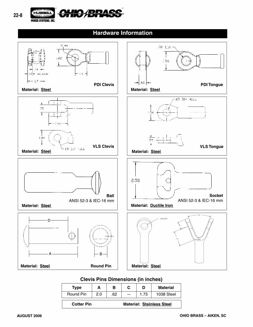
AUGUST 2006 OHIO BRASS – AIKEN, SC
22-
® ®
POWER SYSTEMS, INC.
Hardware Information
PDI Clevis Material: Steel
PDI Tongue Material: Steel
Ball ANSI 52-3 & IEC-16 mm Material: Steel
Socket ANSI 52-3 & IEC-16 mm Material: Ductile Iron
VLS Clevis Material: Steel
VLS Tongue Material: Steel
A
2.0Type
Round PinC
—D
1.75Material
1038 SteelB
.62
Clevis Pins Dimensions (in inches)
Cotter Pin Material: Stainless Steel
Material: Steel Material: Steel Round Pin
D
A B
.88 DIA HOLE
1.91 274887
45?
.94
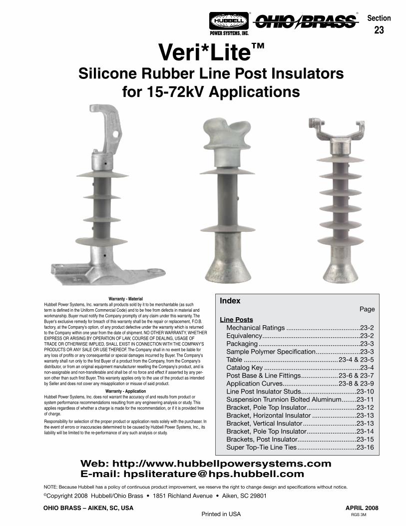
APRIL 2008
23-1
OHIO BRASS – AIKEN, SC, USA
® ®
POWER SYSTEMS, INC.
©Copyright 2008 Hubbell/Ohio Brass • 1851 Richland Avenue • Aiken, SC 29801
Section
23
NOTE: Because Hubbell has a policy of continuous product improvement, we reserve the right to change design and specifications without notice.
Printed in USA RGS 3M
Warranty - MaterialHubbell Power Systems, Inc. warrants all products sold by it to be merchantable (as such term is defined in the Uniform Commercial Code) and to be free from defects in material and workmanship. Buyer must notify the Company promptly of any claim under this warranty. The Buyer's exclusive remedy for breach of this warranty shall be the repair or replacement, F.O.B. factory, at the Company's option, of any product defective under the warranty which is returned to the Company within one year from the date of shipment. NO OTHER WARRANTY, WHETHER EXPRESS OR ARISING BY OPERATION OF LAW, COURSE OF DEALING, USAGE OF TRADE OR OTHERWISE IMPLIED, SHALL EXIST IN CONNECTION WITH THE COMPANY'S PRODUCTS OR ANY SALE OR USE THEREOF. The Company shall in no event be liable for any loss of profits or any consequential or special damages incurred by Buyer. The Company's warranty shall run only to the first Buyer of a product from the Company, from the Company's distributor, or from an original equipment manufacturer reselling the Company's product, and is non-assignable and non-transferable and shall be of no force and effect if asserted by any per-son other than such first Buyer. This warranty applies only to the use of the product as intended by Seller and does not cover any misapplication or misuse of said product.
Warranty - ApplicationHubbell Power Systems, Inc. does not warrant the accuracy of and results from product or system performance recommendations resulting from any engineering analysis or study. This applies regardless of whether a charge is made for the recommendation, or if it is provided free of charge.
Responsibility for selection of the proper product or application rests solely with the purchaser. In the event of errors or inaccuracies determined to be caused by Hubbell Power Systems, Inc., its liability will be limited to the re-performance of any such analysis or study.
IndexPage
Line Posts Mechanical Ratings ........................................23-2 Equivalency .....................................................23-2 Packaging .......................................................23-3 Sample Polymer Specification ........................23-3 Table ...................................................23-4 & 23-5 Catalog Key ....................................................23-4 Post Base & Line Fittings ....................23-6 & 23-7 Application Curves ..............................23-8 & 23-9 Line Post Insulator Studs ..............................23-10 Suspension Trunnion Bolted Aluminum ........23-11 Bracket, Pole Top Insulator ...........................23-12 Bracket, Horizontal Insulator ........................23-13 Bracket, Vertical Insulator .............................23-13 Bracket, Pole Top Insulator ...........................23-14 Brackets, Post Insulator................................23-15 Super Top-Tie Line Ties ................................23-16
Veri*Lite™
Silicone Rubber Line Post Insulatorsfor 15-72kV Applications
Web: http://www.hubbellpowersystems.comE-mail: [email protected]

APRIL 2008 OHIO BRASS – AIKEN, SC, USA
23-2
® ®
POWER SYSTEMS, INC.
Veri*Lite Insulators embody the latest features avail-able in polymer insulator design and manufacture.
Ohio Brass began its efforts in polymer research in the early 1900s. After years of production and research with polymeric compounds in the high voltage insula-tion field, Ohio Brass introduced the Hi*Lite insulator in 1976. A decade later the Ohio Brass polymer distribu-tion arrester, PDV-100, was introduced as the first U.S. made polymer-housed MOV arrester.
Today’s Veri*Lite post insulators build upon the experi-ence of placing nearly 20 million polymer distribution arresters, 17 million polymer deadend distribution insu-lators and 2 million high voltage transmission insula-tors in service. Ohio Brass is dedicated to providing a quality product for the electric utility industry.
DesignThe structural design of the Veri*Lite insulator consists of three basic parts:
Rod - Veri*Lite insulator fiberglass rod is produced from the highest quality materials. Strands are aligned for maximum tensile strength. The rod is filled 65 per-cent, by volume, with electrical grade glass fibers.
End Fittings - Ferrous end fittings are directly crimped to the fiberglass rod by a circumferential crimping pro-cess originated by Ohio Brass. The crimp requires no intermovement of the parts to achieve high strength, nor does it introduce potting compounds or adhesives.
Weathersheds - Veri*Lite insulators are manufactured with OB’s proprietary silicone rubber.
Ohio Brass uses several tests to evaluate materials. Tracking, QUV, corona cutting, salt fog, oxidative sta-bility and variations of differential thermal analysis tests assure the quality of OB’s shed material.
Leakage DistanceVeri*Lite insulators feature high leakage distance for optimum contamination performance.
WashabilityThe Veri*Lite insulators listed in this catalog are suit-able for washing by all known methods in current use. Washing tests have been conducted with high-pres-sure equipment at close nozzle-to-insulator distances. No water intrusion occurred after multiple washings.
StandardsVeri*Lite line post insulators meet ANSI C29.18-2003 and CEA LWIWG-02-1996 standards.
The Ohio Brass facility in Aiken, SC, USA is registered for successful implementation of a quality system in accordance with ISO 9001-2000.
Mechanical RatingsSpecified Cantilever Load (SCL) is the ultimate can-tilever strength rating. Maximum Design Cantilever Load (MDCL) or Working Cantliever Load (WCL) is the maximum continuous cantilever load at which the post insulator should be applied.
MarkingsMarkings are 0.12 inch high raised letters in the rubber and include: Base catalog number, CEA LWIWG Class, SCL in pounds, MDCL/WCL in kN and date code. Ohio Brass identification is cast into the end fittings.
EquivalencyEquivalency of line post insulators involves a check of the general characteristics.
MECHANICAL Compare the SCL of the polymer insulator to the cantilever strength rating of the porcelain insulator.
ELECTRICAL Compare porcelain to Veri*Lite leakage distance. Compare porcelain to Veri*Lite section length.
Insulation CoordinationThe operating performance of a distribution or trans-mission line depends on its insulation level. It must not flashover under practically any operating condition.
Several methods of coordination of line and station insulation have been proposed. Generally, the best method is to establish a definite common insulation level for all the station insulation and then match that level with the line insulation. With this approach, the task is limited to three fundamental requirements:
1. Selection of the Basic Impulse Insulation Level (BIL).
2. Specification of insulation with flashover charac-teristics equal to or greater than the selected BIL.
3. The application of suitable overvoltage surge protection.

APRIL 2008
23-3
OHIO BRASS – AIKEN, SC, USA
® ®
POWER SYSTEMS, INC.
Purpose: To ensure a suitable service life of polymer insulating materials.
I. Material Design Tests - The following must be performed to certify a material for use in production.
1. Tracking test: Performed on a sample of material inclined at 30° and electrodes posi-tioned 35 mm apart. Samples are sprayed with a conductive solution (400 Ωcm) and ener-gized at 10 kV. The cycle is repeated every 90 seconds. The sample passes if there is:
1. No carbonization or tracking. 2. No erosion through sample. 3. No leakage current flow at the end of 90 seconds.
The sample must withstand 20,000 test cycles.
2. Ultraviolet Test: Samples of the rubber must be tested in a QUV tester or equivalent cy-clic weatherometer. The samples are exposed to high ultraviolet radiation and high humid-ity without cracking, checking or becoming hydrophilic.
The sample is judged to have passed this test if it exceeds 8,000 hours of exposure with-out damage.
3. Corona Cutting: Samples 5 cm by 7 cm are subjected to mechanical stress of 300,000 microstrain by bending samples around a grounded electrode. A needle-like electrode is placed 1 mm from the surface of the sample and energized at 12 kV in a controlled humid-ity chamber.
The sample is judged to have passed this test if there is no splitting or cutting. Samples must pass 1,000 hours of exposure to this test.
4. Oxidative Stability: Samples of the polymer compound are tested using differential scanning calorimetry. Samples are heated rapidly in a nitrogen atmosphere to the test temperature of 200°C. The atmosphere is then changed to oxygen and the temperature is maintained until the antioxidant is consumed, as measured by an exothermic chemical reaction. The time for this reaction to occur must exceed 400 minutes.
5. Tear Strength: Rubber test slabs are prepared in accordance with ASTM Standards and are tested to determine tear strength of the material. The acceptable nominal tear strength, per ASTM method B, is 100 lb./in.
II. Other Requirements- The manufacturer must supply upon request a listing of routine tests performed to ensure
production compliance with design tests.
Sample Polymer Specification
Satisfactory performance is generally achieved with an insulator which has a dry 60 Hz flashover of three to five times the phase-to-ground voltage and a leak-age distance approximately twice the shortest air-gap (strike) distance.
PackagingVeri*Lite insulator standard packing is cartons on pal-lets. Larger orders for Veri*Lite posts may be shipped in wood crates.

APRIL 2008 OHIO BRASS – AIKEN, SC, USA
23-4
® ®
POWER SYSTEMS, INC.
kV Post Style Line Base
Catalog Number
ANSI C29.18 Class
CEA LWIWG-02
Class
“X” Dimension
Inches (mm)
Line & Gnd End Shed
Dia. Inches (mm)
Inter- mediate
Shed Quantity
Inter- mediate
Shed Dia. Inches (mm)
Dry Arc Distance Inches (mm)
15
Horz Clamptop Gain 80S015-0100 51-31
LP 15
12.5 (318)
4.8 (121) 0 7.4 (188)Horz Clamptop 3/4-10 Tap 80S015-0109 51-21 13.3 (339)Vert Clamptop 3/4-10 Tap 80S015-0209 51-11 12.8 (324)Vert F-Neck 3/4-10 Tap 80S015-0F09 51-1F 12.4 (315)
25
Horz Clamptop Gain 80S025-0100 51-32
LP 25
14.3 (362)
5.2 (132) 2 3.8 (9.6) 9.6 (244)Horz Clamptop 3/4-10 Tap 80S025-0109 51-22 15.1 (383)Vert Clamptop 3/4-10 Tap 80S025-0209 51-12 14.5 (368)Vert F-Neck 3/4-10 Tap 80S025-0F09 51-2F 14.2 (360)
35
Horz Clamptop Gain 80S028-0100 51-33
LP 28M
16.5 (420)
5.1 (130) 4 4.6 (117) 11.7 (297)Horz Clamptop 3/4-10 Tap 80S028-0109 51-23 17.4 (441)Vert Clamptop 3/4-10 Tap 80S028-0209 51-13 16.8 (425)Vert F-Neck 3/4-10 Tap 80S028-0F09 51-3F 16.5 (418)
46
Horz Blade Gain 80S046-0000 – –
LP 46
19.2 (488)
7.1 (179) 6 4.4 (112) 14.4 (390)
Horz Blade 3/4-10 Tap 80S046-0009 – – 20.0 (508)Horz Clamptop Gain 80S046-0100 51-34 19.0 (482)Horz Clamptop 3/4-10 Tap 80S046-0109 51-24 19.8 (504)Vert Clamptop 3/4-10 Tap 80S046-0209 51-14 20.1 (510)Vert F-Neck 3/4-10 Tap 80S046-0F09 51-4F 19.5 (495)
69
Horz Blade Gain 80S069-0000 – –
LP 69M
25.8 (656)
7.5 (190) 8 5.2 (132 22.3 (566)
Horz Blade 3/4-10 Tap 80S069-0009 – – 26.6 (676)Horz Clamptop Gain 80S069-0100 51-36 25.6 (650)Horz Clamptop 3/4-10 Tap 80S069-0109 51-26 26.5 (672)Vert Clamptop 3/4-10 Tap 80S069-0209 51-16 26.8 (680)Vert F-Neck 3/4-10 Tap 80S069-0F09 – – 26.1 (663)
72
Horz Blade Gain 80S072-0000 – –
– –
28.7 (728)
7.8 (198) 12 5.5 (140) 25.4 (645)
Horz Blade 3/4-10 Tap 80S072-0009 – – 29.6 (752)Horz Clamptop Gain 80S072-0100 – – 28.7 (728)Horz Clamptop 3/4-10 Tap 80S072-0109 – – 29.6 (751)Vert Clamptop 3/4-10 Tap 80S072-0209 – – 29.7 (754)Vert F-Neck 3/4-10 Tap 80S072-0F09 – – 29.1 (740)
8 0 S 0 6 9 0 2 0 9
Polymer Type Bottom End Fitting
80S Veri*Lite - SR Polymer 00 Gain Base - Transverse
09 3 /4” Stud Base
Hardware Finish 10 7/8” Stud Base
0 Standard
Top End Fitting
Rating 0 Teardrop Blade*
15 15kV (1.5” rod) 1 Horizontal Clamptop
25 25kV (1.5” rod) 2 Veritical Clamptop
28 35kV (1.5” rod) 5 5” B.C. Through
46 46kV (1.75” rod) 6 Horizontal Clamptop (longer pintle bolt)
69 69kV (1.75” rod) A Vertical Clamptop (longer pintle bolt)
72 72kV (1.75” rod) F F-neck
Dimensioning
0 ANSI C29.18 Quality Conformance Tests
6 LWIWG - 02 Sample Tests
*Teardrop Blade only available for 46-72kV 9 Special
CATALOG NUMBER KEYVeri*Lite Line Post Insulators - Silicone

APRIL 2008
23-5
OHIO BRASS – AIKEN, SC, USA
® ®
POWER SYSTEMS, INC.
NOTES:1. Maximum Design Tension for Clamptop is 2500 pounds (11 kN)2. 15, 25 & 28 kV Units use 1.5 inch (38 mm) Diameter Rod3. 46, 69 & 72 kV Units use 1.75 inch (44 mm) Diameter Rod
Horizontal Clamptop & Gain Base (0100)
Vertical Clamptop & Stud Base (0209 & 0210)
F-Neck & Stud Base (0F09 & 0F10)
Leakage Distance Inches (mm)
60 Hz (Low Frequency)
Flashover
Impulse Critical
Flashover Pos. kV
Impulse Positive
Withstand kV
SCL pounds
(kN)
MDCL/ WCL
pounds (kN)
Net Weight pounds
(kg)
Standard Package Quantity
kV Dry-kV Wet-kV Carton Pallet Max/Crate
11.0 (279) 90 70 150 140 2800 (12.5) 1235 (5.5)
9.8 (4.5)
3
36
– – 156.9 (3.1) 606.5 (2.9) 606.6 (3.0) 60
17.3 (439) 110 75 185 170 2800 (12.5) 1235 (5.5)
10.3 (4.7)
3
36
– – 257.3 (3.3) 607.0 (3.2) 607.1 (3.2) 60
26.1 (662) 135 100 215 200 2800 (12.5) 1235 (5.5)
11.2 (5.1)
3
36
– – 358.2 (3.7) 607.8 (3.5) 608.0 (3.6) 60
34.3 (872) 170 125 260 235 2800 (12.5) 1235 (5.5)
19.7 8.9)
– – – –
14/21/28/35
46
14.6 (6.6) 7018.6 (8.4) 14/21/28/3513.5 (6.1) 7014.1 (6.4) 7013.9 (6.3) 70
58.2 (1478) 230 180 360 330 2470 (11.0) 1235 (5.5)
22.1 (10.0)
– – – –
14/21/28/35
69
16.9 (7.7) 3521.0 (9.5) 14/21/28/3515.9 (7.2) 3516.5 (7.5) 3512.0 (5.4) 35
71.0 (1803) 270 230 400 450 2030 (9.0) 1015 (4.5)
23 (10.4)
– – – –
14/21/28/35
72
17.9 (8.1) 3522 (10.0) 14/21/28/3516.8 (7.6) 3517.4 (7.9) 3517.3 (7.8) 35

APRIL 2008 OHIO BRASS – AIKEN, SC, USA
23-6
® ®
POWER SYSTEMS, INC.
B
A
D
FC
I
H
Post Line Fittings Dimensions (in inches)
Post Base & Line Fittings
15, 25 & 35 kVStud Base
15, 25 & 35 kVHorizontal Gain Base
Line Post Line Fittings Dimensions (in inches)
15-72 kVVertical Clamptop Cap
15-72 kVHorizontal Clamptop Cap
4.0
2.11
2.25
Post Base Fittings Dimensions (in inches)
Type A B C D E F H I Material
H. Clamptop Cap 4.00 4.75 0.62 0.38 0.69 5/8-11 UFS-2B - - 60-40-18 DI
V. Clamptop Cap 4.00 5.38 1.12 0.38 - 5/8-11 UFS-2B 3.38 1.63 60-40-18 DI

APRIL 2008
23-7
OHIO BRASS – AIKEN, SC, USA
® ®
POWER SYSTEMS, INC.
Line Post Base Fittings Dimensions (in inches)
Post Base & Line Fittings
46, 69 & 72 kV Stud Base46, 69 & 72 kV Horizontal Gain Base
46, 69 & 72 kV Two Hole Blade15-72 kV F-Neck Cap
B
A
E
DC
3/4-10 UFS-2B THREAD7/8-9 UFS-2B THREAD
Type A B C D E F G H Material
H. Gain Base 14.50 7.00 12.00 10.00 6.75 1.25 x 0.88 0.88 4.00 60-40-18 DI
Stud Base 4.22 2.875 5.50 1.50 0.50 3/4-10 UFS-2B or 7/8-9 UFS-2B
- - 60-40-18 DI
Two Hole Blade 2.75 1.38 0.50 4.00 0.75 1.00 Dia. 0.50 R 0.44 R 60-40-18 DI

APRIL 2008 OHIO BRASS – AIKEN, SC, USA
23-8
® ®
POWER SYSTEMS, INC.
values, find the allowable longitudinal load to be 900 pounds.
When the posts are loaded in tension the cantilever loading due to the combined effects of longitudinal, vertical and tensile loads should not exceed the rated tension working value.
IMPORTANT: The application curves should not be extrapolated.
How to use the application curves. After you have established the loading cases, you can use the curves to determine whether a specific Veri*Lite unit meets your loading requirement.
For example, consider the installation of a Veri*Lite post number 80S025-0100 on a line with a vertical cantilever load of 800 pounds and a compression load of 900 pounds. By entering the curve at these
Maximum deflection for any of the post styles is approximately 1.75" at SCL.Curves are shown using a 2.0 safety margin to SCL
Application Curves for Veri*Lite Insulators
80S015, 80S025 & 80S028 HORIZONTAL STYLE
80S015, 80S025 & 80S028 VERTICAL STYLE
0
200
400
600
800
1000
1200
1400
VERTICAL LOAD, LBF
0 Longitudinal300 Longitudinal600 Longitudinal900 Longitudinal1200 Longitudinal
Compression TensionLINE POSTAPPLICATION CURVES9-12-05
-3000 -2000 -1000 0 1000 2000 3000
TR
AN
SV
ER
SE
LO
AD
, LB
F
0
200
400
600
800
1000
1200
1400
-3000 -2000 -1000 0 1000 2000 3000
VERTICAL LOAD, LBF
0 Longitudinal300 Longitudinal600 Longitudinal900 Longitudinal
CompressionTRANSVERSE LOAD, LBF
LINE POST APPLICATION CURVES9-12-05
Tension
VE
RT
ICA
L L
OA
D, L
BF
1200 Longitudinal

APRIL 2008
23-9
OHIO BRASS – AIKEN, SC, USA
® ®
POWER SYSTEMS, INC.
values, find the allowable longitudinal load to be 900 pounds.
When the posts are loaded in tension the cantilever loading due to the combined effects of longitudinal, vertical and tensile loads should not exceed the rated tension working value.
IMPORTANT: The application curves should not be extrapolated.
How to use the application curves. After you have established the loading cases, you can use the curves to determine whether a specific Veri*Lite unit meets your loading requirement.
For example, consider the installation of a Veri*Lite post number 80S069-0100 on a line with a vertical cantilever load of 800 pounds and a compression load of 900 pounds. By entering the curve at these
Maximum deflection for any of the post styles is approximately 1.75" at SCL.Curves are shown using a 2.0 safety margin to SCL
80S046 & 80S069 HORIZONTAL STYLE
Application Curves for Veri*Lite Insulators
0
200
400
600
800
1000
1200
1400
-3000 -2000 -1000 0 1000 2000 3000
VERTICAL LOAD, LBF
Compression TRANSVERSE LOAD, LBF
LINE POST APPLICATION CURVES9-12-05
Tension
0 Longitudinal300 Longitudinal600 Longitudinal900 Longitudinal1200 Longitudinal
VE
RT
ICA
L L
OA
D, L
BF
80S046 & 80S069 VERTICAL STYLE
0
200
400
600
800
1000
1200
1400
VERTICAL LOAD, LBF
0 Longitudinal
300 Longitudinal
600 Longitudinal
900 Longitudinal
1200 Longitudinal
Compression Tension
TR
AN
SV
ER
SE
LO
AD
, LB
F
LINE POSTAPPLICATION CURVES9-12-05
1000 2000 3000-1000-2000-3000
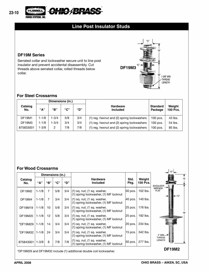
APRIL 2008 OHIO BRASS – AIKEN, SC, USA
23-10
® ®
POWER SYSTEMS, INC.
Line Post Insulator Studs
DF19M SeriesSerrated collar and lockwasher secure unit to line post insulator and prevent accidental disassembly. Cut threads above serrated collar, rolled threads below collar.
DF19M3
For Steel Crossarms
DF19M2
For Wood Crossarms
*DF19M29 and DF19M32 include (1) additional double coil lockwasher.
CatalogNo.
DF19M1
DF19M3
875833001
Dimensions (in.)
“D”
3/4
3/4
7/8
“A”
1-1/8
1-1/8
1-3/8
“B”
1-3/4
1-3/4
2
“C”
5/8
3/4
7/8
HardwareIncluded
(1) reg. hexnut and (2) spring lockwashers
(1) reg. hexnut and (2) spring lockwashers
(1) reg. hexnut and (2) spring lockwashers
Standard Package
100 pcs.
100 pcs.
100 pcs.
Weight100 Pcs.
43 lbs.
54 lbs.
85 lbs.
Dimensions (in.)
“D”
3/4
3/4
3/4
3/4
3/4
3/4
7/8
“A”
1-1/8
1-1/8
1-1/8
1-1/8
1-1/8
1-1/8
1-3/8
“B”
7
7
10
12
14
24
8
“C”
5/8
3/4
5/8
5/8
3/4
3/4
7/8
HardwareIncluded
(1) sq. nut, (1 sq. washer, (1) spring lockwasher, (1) MF locknut
(1) sq. nut, (1 sq. washer, (1) spring lockwasher, (1) MF locknut
(1) sq. nut, (1 sq. washer, (1) spring lockwasher, (1) MF locknut
(1) sq. nut, (1 sq. washer, (1) spring lockwasher, (1) MF locknut
(1) sq. nut, (1 sq. washer, (1) spring lockwasher, (1) MF locknut
(1) sq. nut, (1 sq. washer, (1) spring lockwasher, (1) MF locknut
(1) sq. nut, (1 sq. washer, (1) spring lockwasher, (1) MF locknut
CatalogNo.
DF19M2
DF19M4
DF19M19
DF19M20
*DF19M29
*DF19M32
875843001
Std. Pkg.
50 pcs.
40 pcs.
25 pcs.
25 pcs.
20 pcs.
15 pcs.
50 pcs.
Weight100 Pcs.
102 lbs.
140 lbs.
176 lbs.
192 lbs.
234 lbs.
342 lbs.
277 lbs.
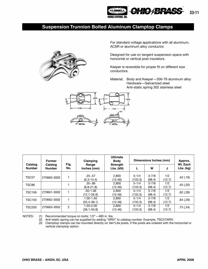
APRIL 2008
23-11
OHIO BRASS – AIKEN, SC, USA
® ®
POWER SYSTEMS, INC.
For standard voltage applications with all aluminum, ACSR or aluminum alloy conductor.
Designed for use on tangent suspension spans with horizontal or vertical post insulators.
Keeper is reversible for proper fit on different size conductors.
Material: Body and Keeper—356-T6 aluminum alloy Hardware—Galvanized steel Anti-static spring 302 stainless steel
NOTES: (1) Recommended torque on bolts; 1/2”—480 in. lbs. (2) Anti-static spring can be supplied by adding “ARIV” to catalog number. Example, TSC57ARIV.
(3) Clamptop clamps can be mounted directly on Veri*Lite posts, if the posts are ordered with the horizontal or vertical clamptop option.
Fig.No.
1
1
1
1
2
ClampingRange
Inches (mm)
.25-.57(6.3-14.4).35-.86
(8.8-21.8).50-1.06
(12.7-26.9)1.00-1.50(25.4-38.1)1.50-2.00(38.1-50.8)
UltimateBody
StrengthLbs. (kN)
2,800(12.46)2,800(12.46)2,800(12.46)2,800(12.46)2,800(12.46)
L
5-1/4(133.3)5-1/4
(133.3)5-1/4
(133.3)5-1/4
(133.3)5-1/4
(133.3)
W
3-7/8(98.4)3-7/8(98.4)3-7/8(98.4)3-7/8(98.4)3-7/8(98.4)
J
1/2(12.7)1/2
(12.7)1/2
(12.7)1/2
(12.7)1/2
(12.7)
Approx.Wt. EachLbs. (kg)
.42 (.19)
.45 (.20)
.62 (.28)
.64 (.29)
.75 (.34)
Dimensions Inches (mm)
Suspension Trunnion Bolted Aluminum Clamptop Clamps
Former CatalogNumber
270660-3002
270661-3002
270662-3002
270663-3002
CatalogNumber
TSC57
TSC86
TSC106
TSC150
TSC200
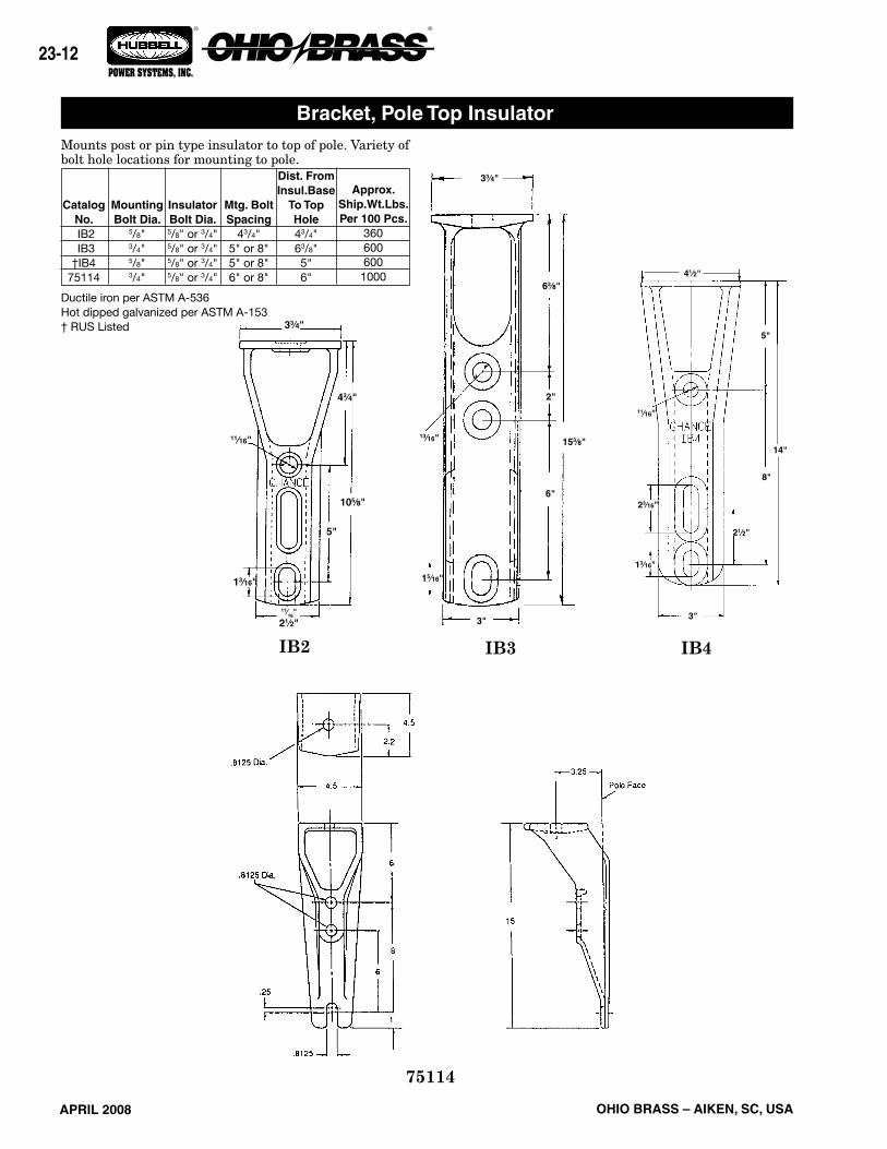
APRIL 2008 OHIO BRASS – AIKEN, SC, USA
23-12
® ®
POWER SYSTEMS, INC.
Mounts post or pin type insulator to top of pole. Variety of bolt hole locations for mounting to pole.
Ductile iron per ASTM A-536Hot dipped galvanized per ASTM A-153† RUS Listed
IB4
11⁄16"
43⁄4"
105⁄8"
5"
11⁄16"21⁄2"
13⁄16"
33⁄4"
IB2 IB3
33⁄4"
2"
6"
153⁄8"
3"
63⁄8"
15⁄16"
13⁄16"
3"
11⁄16"
41⁄2"
5"
8"
13⁄16"
23⁄16"
21⁄2"
14"
Bracket, Pole Top Insulator
75114
CatalogNo. IB2 IB3†IB4
75114
Mounting Bolt Dia.
5/8" 3/4" 5/8" 3/4"
Insulator Bolt Dia.5/8" or 3/4"5/8" or 3/4"5/8" or 3/4"5/8" or 3/4"
Mtg. Bolt Spacing
43/4"5" or 8"5" or 8"6" or 8"
Dist. From Insul.Base
To Top Hole43/4"63/8"5" 6"
Approx. Ship.Wt.Lbs.Per 100 Pcs.
3606006001000
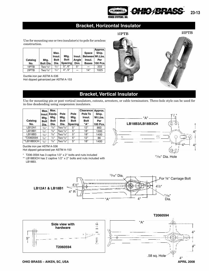
APRIL 2008
23-13
OHIO BRASS – AIKEN, SC, USA
® ®
POWER SYSTEMS, INC.
Use for mounting one or two insulator(s) to pole for armless construction.
Approx. Ship.
Wt.Lbs.Per
100 Pcs.3331025
Space Between
Insul. Bases
—14"
Insul.AngleDim.
5°—
Mtg. Bolt
Spacing5", 6"4", 5"
Max.Insul.BoltDia. 3/4" 3/4"
Mtg. Bolt Dia.Two 5/8" Two 5/8"
CatalogNo.
1IPTB2IPTB
Ductile iron per ASTM A-536Hot dipped galvanized per ASTM A-153
Use for mounting pin or post vertical insulators, cutouts, arresters, or cable terminators. Three-hole style can be used for in-line deadending using suspension insulators.
2IPTB
Max.Insul.Mtg.Bolt Dia. 3/4" 3/4" 3/4"3/4"3/4"
PoleMtg. Bolt Dia.
Two 5/8" Two 5/8" Two 5/8"Two 5/8"Two 5/8"
Max.Equip.Mtg.Bolt Dia. 5/8"5/8" 5/8"1/2"5/8"
Pole Mtg. Bolt
Spacing5"5"5"5"5"
Clearance Pole To Insul. Bolt"A"12"18"18"12"18"
Approx. Ship.
Wt.Lbs.Per
100 Pcs.8601300140086
1400
4"
4"
4"
"A"
.58 sq. Hole
T2060594
Side view with hardware
LB12A1 & LB18B14" R
41⁄2"
4"
41⁄2"
For 3⁄8" Carriage Bolt13⁄16" Dia.
"A"
5"
LB18B3/LB18B3CH
"A"
11⁄16" Dia. Hole
4"
4"
11/4"
CatalogNo.
LB12A1LB18B1LB18B3
*T2060594**LB18B3CH
Ductile iron per ASTM A-536Hot dipped galvanized per ASTM A-153
* T206-0594 has 3 captive 1/2" x 2" bolts and nuts included** LB18B3CH has 2 captive 1/2" x 2" bolts and nuts included with
LB18B3.
11⁄16" Dia.
4"
Bracket, Horizontal Insulator
Bracket, Vertical Insulator
1IPTB
T2060594

APRIL 2008 OHIO BRASS – AIKEN, SC, USA
23-14
® ®
POWER SYSTEMS, INC.
BRACKET, ANGLE CROSSARM
Ductile iron per ASTM A-536Hot dipped galvanized per ASTM A-153
Mounts post insulators at 30° angle on crossarm for use on running corners.
Bracket, Pole Top Insulator
CatalogNo.
1XAB
CrossarmSize
33/4" x 43/4" Max. and
RoundCrossarms
Approx. Ship Wt. Lbs.
Per 100 Pcs.
610
Mtg. BoltDiameter
3/4"
Stud BoltDiameter
3/4"

APRIL 2008
23-15
OHIO BRASS – AIKEN, SC, USA
® ®
POWER SYSTEMS, INC.
11/16" Hole16919
InsulatorStud
Bolts Required3/4"3/4"
13/16" Hole†*C2060209 C2060162
PoleMounting
Bolts RequiredTwo 5/8"Two 5/8"
Approx. ShipWt. Lbs.
Per 100 Pcs.650440
*This bracket is designed to facilitate a stringing block.†RUS listed
Catalog Number
BRACKETS, POST INSULATORSide Mounted
The bracket is formed of high-quality 3/8" x 21/2" bar steel and hot dip galvanized. It can be utilized to mount distribution post insulators from 15 kV to 34.5 kV.
BRACKETS, POST INSULATORCurved base
This bracket can be used for mounting distribution post-type insulators from 15 kV to 34.5 kV on the side of the pole. The base has a pole-shape back for convenient installation. Brackets can be placed in a phase-over- phase arrangement or can be mounted on opposite sides of the pole for "armless" construction.
Insulators not included.
BRACKETS, POST INSULATORUni-Brackets
Chance Uni-Brackets are a clean-appearing, low-cost method of mount-ing three post-type insulators atop a pole completely eliminating the crossarm. The brackets can be installed on the pole in less than five minutes, requiring only two 3/4" bolts for attachment. Uni-Brackets fit poles having a pole-top diameter from 6" to 81/2". Slot on top is 11/16" x 21/4".
No. 9183 brackets can be adapted to a variety of distribution construc-tion using post-type insulators from 15 through 34.5 kV.
CatalogNumber†9183
Approx. Ship Wt.Lbs. Per 100 Pcs.
2100
Insulator StudBolts Required
5/8"
†Includes both sections of bracket
C2060162 C2060209
AngleA
15°15°15°
W444
D13/1613/1613/16
L 91/2
12 15
Catalog Number
*C2060009†*C2060010 C2060011
DimensionsIn Inches
*These brackets have 13/16" stringing block holes.†RUS listed
Approx.Ship
Wt. Lbs.Per 100 Pcs.
122016692066
81/4"
11/16" Holes
13/16" Hole
13/16" x 11/4" Hole
3/8" x 21/2" Stock
60° 91/2"
1817/32"
No. 9183
13/16" hole
81/2"
11/16" hole
11/16" x 13/8" slot
51/4"
30°
11/16" x 13/8" slot
83/4"
13/16" hole 30°
13/16" hole41/2"
11/16" hole
13/16" x 15/16" slot
81/2"
C2060009
31/2" RW
11/16" Dia. holeL3/8" X
A
D10"
load table11/16" x 11/4" slot
41/2"

APRIL 2008 OHIO BRASS – AIKEN, SC, USA
23-16
® ®
POWER SYSTEMS, INC.
SUPER TOP-TIE® Line Ties• for Pin, Post and Spool InsulatorsMade of aluminum-clad steel compatible with aluminum, aluminum-alloy and ACSR conductors in the top grooves of vertical-mounted *ANSI Class C, F, J and many non-standard pin and post insulators (single-or double-support) or on *ANSI 53-2 spool insulators (horizontal or vertical).
High-density polyethylene hooks provide the wide applica-tion range and ensure proper installation. If used over armor rods (not required), select tie size based on total conductor/armor diameter. Semiconductive-rubber pad and high-density-polyethylene on loops protect against abrasion of insulator, conductor and tie. Fit is resilient and provides superior performance under galloping and aeolian vibration. Install by hand or with hot-line tools.
Manufactured and/or for use under U.S. Patent 4,015,073.
POSTINSULATOR
PININSULATOR
NON-STANDARDINSULATOR
ANSI 53-2SPOOL
ORDERING INFORMATION
ACSR#6, 6/1#4, 6/1#3, 6/1#2, 6/1#1, 6/11/0, 6/12/0, 6/13/0, 6/14/0, 6/1
266.8, 18/1336.4, 18/1477, 18/1
556.5, 18/1
ColorCodeNone
OrangePurpleRedGray
YellowBlueBlackPink
GreenBrownVioletGold
Std.Pkg.50505050505050505050505050
Wt. Per100, Lb.
28282828283232323232404040
AAC(All-Aluminum)
#6, 7W#4, 7W#3, 7W#2, 7W#1, 7W1/0, 7W2/0, 7W3/0, 7W4/0, 7W
266.8, 19W336.4, 19W477, 19W636, 37W
AAAC(Alum.-Alloy)
#6, 7W#4, 7W#3, 7W#2, 7W#1, 7W1/0, 7W2/0, 7W3/0, 7W4/0, 7W
266.8, 19W336.4, 19W477, 19W
556.5, 19W
Diameter Range.184-.220" (4.67-5.59 mm).221-.257" (5.61-6.53 mm).258-.289" (6.55-7.34 mm).290-.325" (7.37-8.26 mm).326-.360" (8.28-9.14 mm)
.361-.409" (9.17-10.39 mm).410-.460" (10.41-11.68 mm).461-.516" (11.71-13.11 mm).517-.584" (13.13-14.83 mm).585-.664" (14.86-16.87 mm).665-.755" (16.89-19.18 mm).756-.859" (19.20-21.82 mm).860-.977" (21.84-24.82 mm)
Aluminum-Type Conductors, Typical SizesCatalogNumberSTT10STT20STT30STT40STT50STT60STT70STT80STT90STT100STT110STT120STT130
LEFT-HAND LAY STANDARD• Applied Length: 29" - 48" (Depends on insulator make and conductor size).• Strength: Exceeds Rule 261E.2(A) of National Electrical Safety Code.• REA accepted.• To obtain outside diameters of conductors, consult Conductor Chart.
*Super Top-Tie STT10 — STT130 also fit many foreign or reclaimed pin and post insulators with neck sizes 21/4" - 31/2".Consult Hubbell Power Systems, Inc. for use on pins and posts outside these dimensions.