akd basic modbus quick start part 1 rev a
TRANSCRIPT

1
Simple Example To Test AKD BASIC Modbus TCP Communications ( Part 1: using Modbus Poll ) Rev. A
9/25/2019
This application note will demonstrate how to prove you can read and write to the AKD BASIC variables
over Modbus TCP. We will do this first with a software based Modbus TCP Master called Modbus Poll
and then show a basic example using Kollmorgen Visualization Builder software in Part 2 of this series.
The support group at Kollmorgen have the licensed version but you can download the demo version
( with a limited run-time ) at https://www.modbustools.com/modbus_poll.html
There are several ranges of Modbus TCP Parameters ( and addresses ) in the AKD-B, -P, and -T drives
( note the AKD-P-NBPN, Profinet drive does not support Modbus TCP ).
The Modbus Manual is embedded in Workbench Help. See each individual parameter descriptions to
determine if the parameter is supported by the AKD-T ( AKD BASIC ) or not.

2
In addition to the standard parameter table and the Modbus 64bit Parameters to 32bit Parameters
there are also registers that can be mapped to variables in the AKD BASIC Program so a HMI or PLC can
read/write values from/to the AKD BASIC program. In this case there is a specific section of Workbench
under AKD BASIC Proramming Manual->AKD BASIC Language->AKD BASIC Modbus. Per below the
available address range is from 5000 to 5999 ( each 16 bit integer registers ).
Note in order for the 5000 range ( AKD BASIC variables Modbus ) registers to be valid and not produce
Modbus errors on attempt to access the AKD BASIC program must run and on execution declare
variables ( and possibly initialize them to default values ) and map them to specific Modbus registers ( in
the 5000 range ).
3
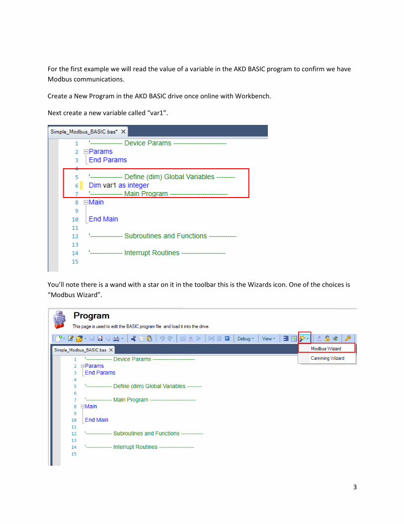
For the first example we will read the value of a variable in the AKD BASIC program to confirm we have
Modbus communications.
Create a New Program in the AKD BASIC drive once online with Workbench.
Next create a new variable called “var1”.
You’ll note there is a wand with a star on it in the toolbar this is the Wizards icon. One of the choices is
“Modbus Wizard”.

4
Selecting the Modbus Wizard calls up the following window that allows you to map a Modbus address to
the variable we just created.
Click on the + button in the bottom left side of the Modbus Wizard window. It will add a variable starting
at 5000. At this point it is possible to make changes to the setup for this first item in the list so I changed
the variable name to “var1” and the type of register to “32-bit”. This means over Modbus the high word
will be 5000 and the low word is 5001 ( 2 consecutive 16 bit registers ). It is possible to use dynamic
mapping to do word swapping but often the Modbus TCP master can handle it if required. This is
beyond the scope of this Quick Start. Click ok to accept the changes.

5
Note between Dim and Main the Modbus mapping is now declared MBINFO:End and inside the
declaration is the mapping of the 32 bit variable, var 1, and the starting address 5000.
6
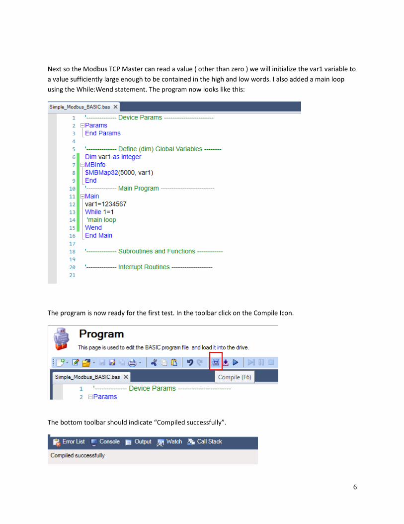
Next so the Modbus TCP Master can read a value ( other than zero ) we will initialize the var1 variable to
a value sufficiently large enough to be contained in the high and low words. I also added a main loop
using the While:Wend statement. The program now looks like this:
The program is now ready for the first test. In the toolbar click on the Compile Icon.
The bottom toolbar should indicate “Compiled successfully”.

7
Next download the compiled program to the drive.
The status bar at the bottom of the Program screen in Workbench should indicated “Downloaded
successfully” and the name of the program should be at the far right.
Finally run the program by pressing the Run icon in the toolbar.
The status bar should show Running and a scanning bar to the left of the Program name should also
indicate the program is running.
At this point the only thing the program does is map the var1 parameter to Modbus TCP addresses and
initializes it to a value.
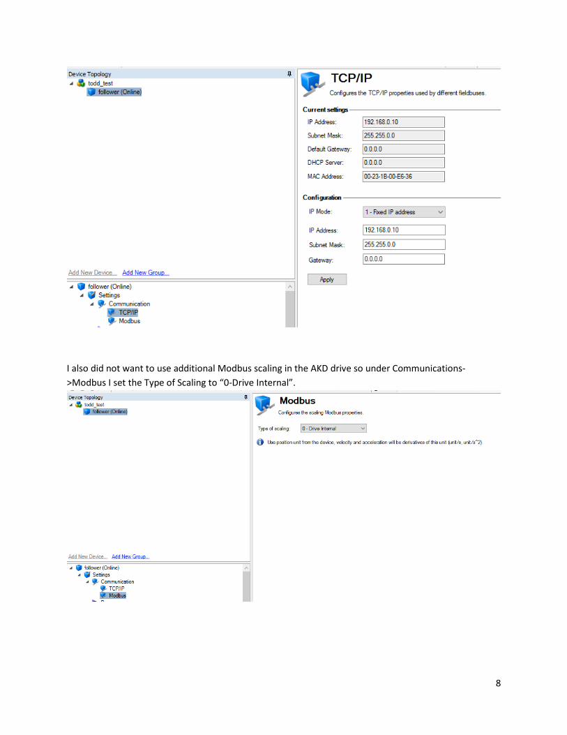
In my AKD BASIC drive the following IP Address was set:
8
I also did not want to use additional Modbus scaling in the AKD drive so under Communications-
>Modbus I set the Type of Scaling to “0-Drive Internal”.
9
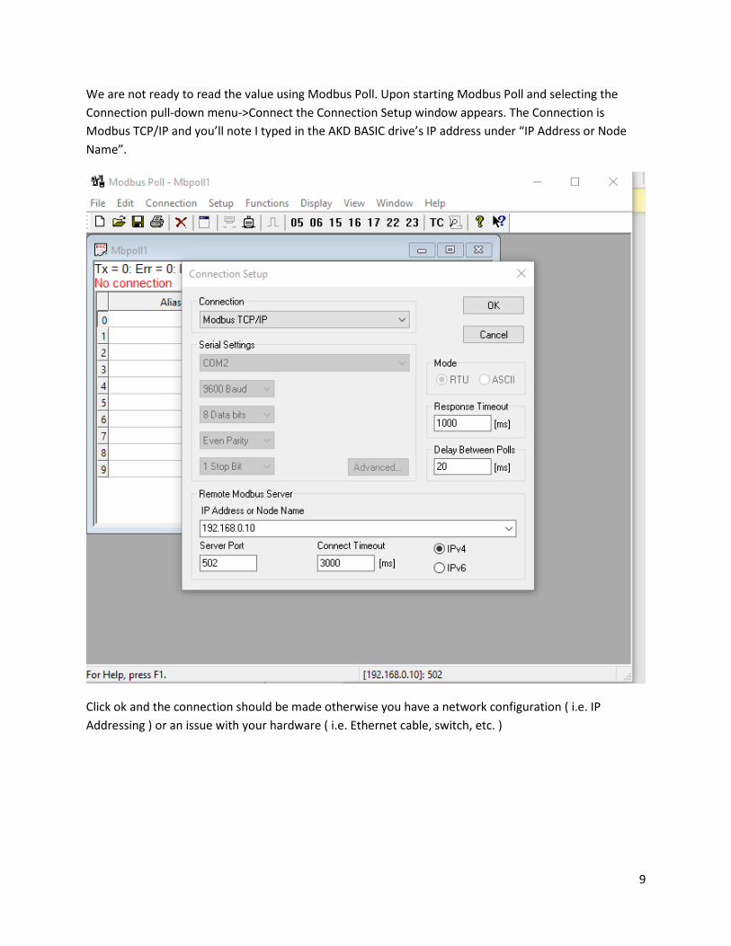
We are not ready to read the value using Modbus Poll. Upon starting Modbus Poll and selecting the
Connection pull-down menu->Connect the Connection Setup window appears. The Connection is
Modbus TCP/IP and you’ll note I typed in the AKD BASIC drive’s IP address under “IP Address or Node
Name”.
Click ok and the connection should be made otherwise you have a network configuration ( i.e. IP
Addressing ) or an issue with your hardware ( i.e. Ethernet cable, switch, etc. )

10
Under the Setup pull-down menu select Read/Write Definition
The following setup is used. Note this will setup Modbus Poll to read holding registers starting at
address 5000 and a quantity of 2 ( registers 5000 and 5001 ). I set the scan ( poll ) rate to 50ms for this
example and then clicked on ok.

11
The Tx counter should be counting and Err=0 ( no Modbus errors ). There are values in address 5000 and
5001 but they are formatted as 16 bit registers ( recall the AKD BASIC program formatted the variable as
32 bit ).
To display a different format in Modbus poll highlight the 2 registers as follows using your mouse.
12
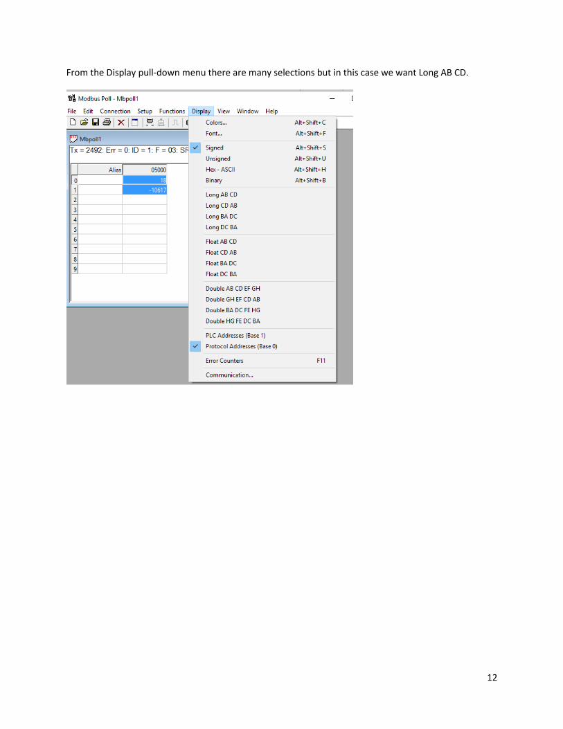
From the Display pull-down menu there are many selections but in this case we want Long AB CD.
13
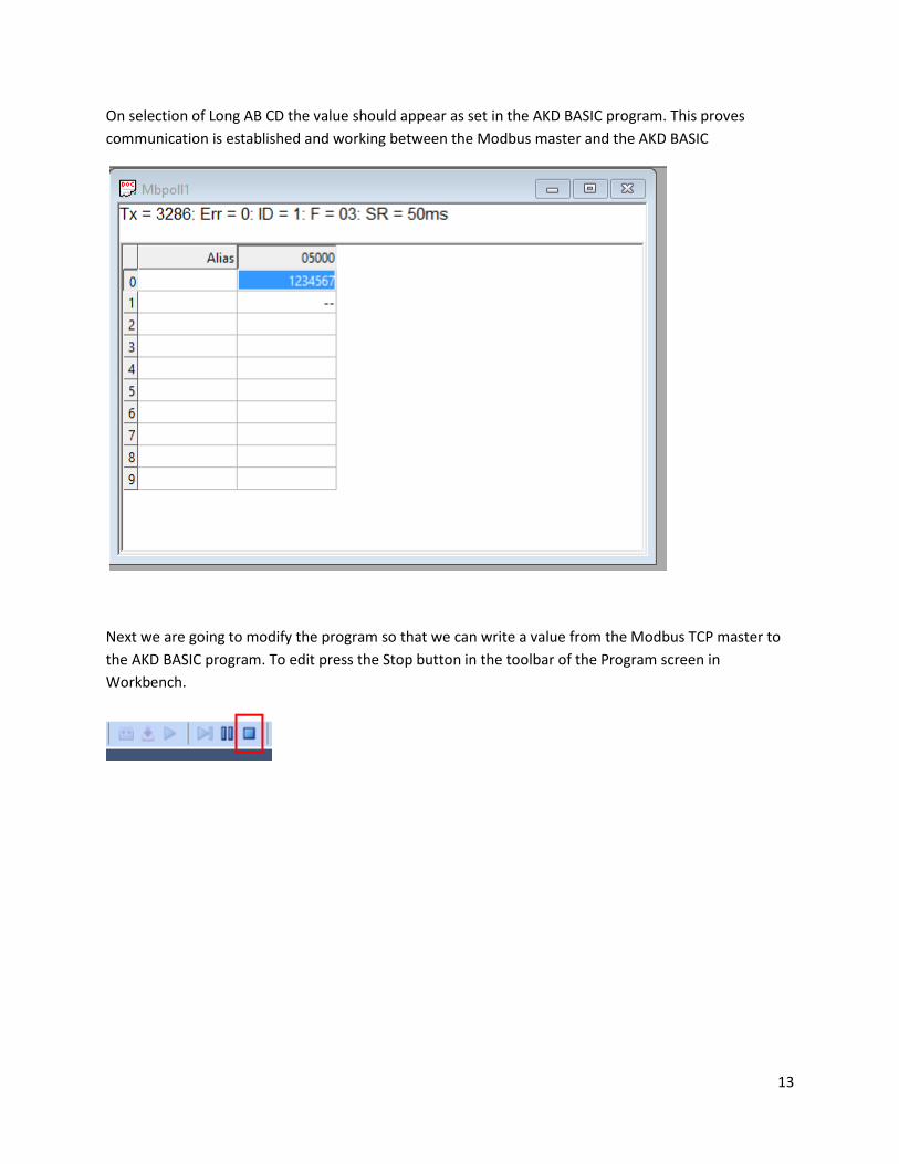
On selection of Long AB CD the value should appear as set in the AKD BASIC program. This proves
communication is established and working between the Modbus master and the AKD BASIC
Next we are going to modify the program so that we can write a value from the Modbus TCP master to
the AKD BASIC program. To edit press the Stop button in the toolbar of the Program screen in
Workbench.
14
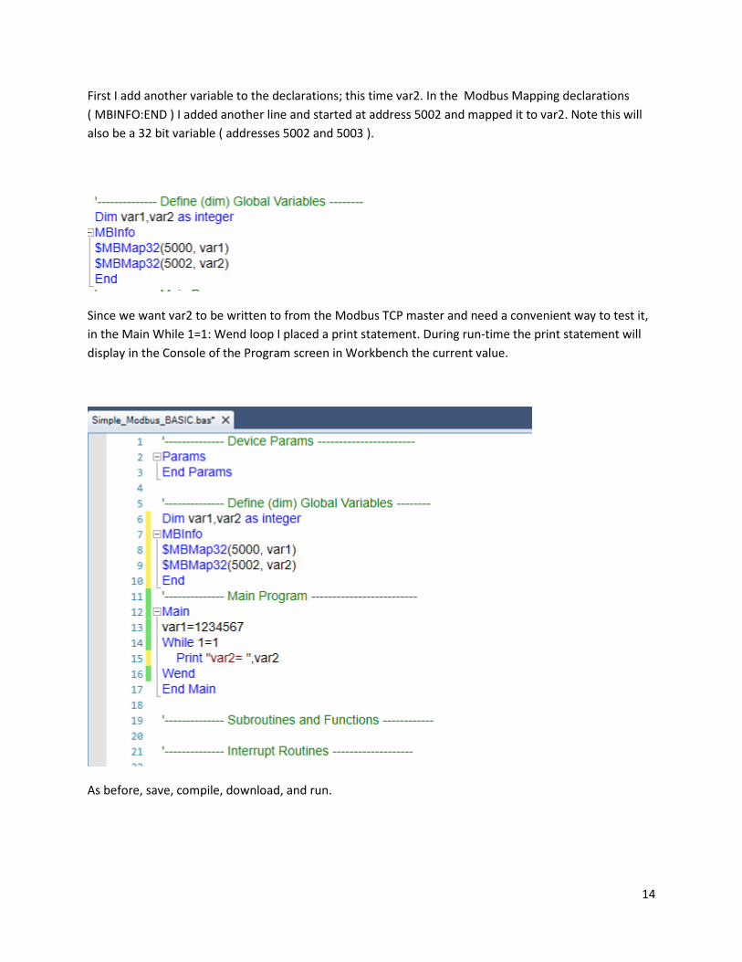
First I add another variable to the declarations; this time var2. In the Modbus Mapping declarations
( MBINFO:END ) I added another line and started at address 5002 and mapped it to var2. Note this will
also be a 32 bit variable ( addresses 5002 and 5003 ).
Since we want var2 to be written to from the Modbus TCP master and need a convenient way to test it,
in the Main While 1=1: Wend loop I placed a print statement. During run-time the print statement will
display in the Console of the Program screen in Workbench the current value.
As before, save, compile, download, and run.
15
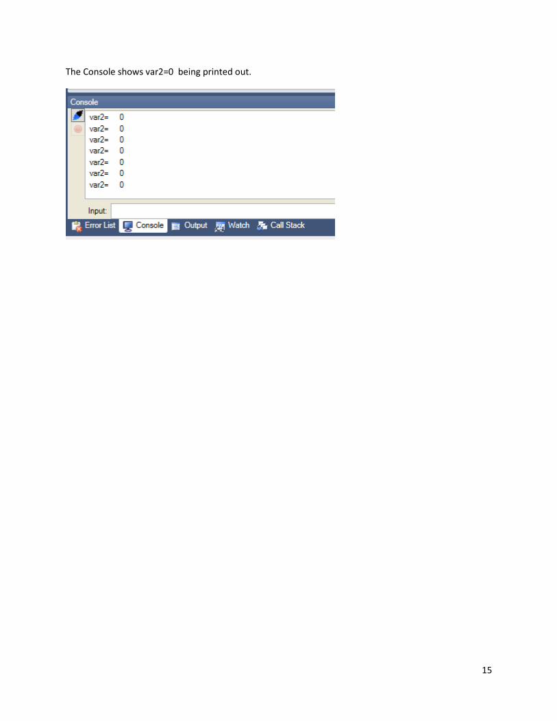
The Console shows var2=0 being printed out.

16
In Modbus Poll I select File->New to setup the Write. Under Setup->Read/Write Definition I selected 16-
Write Multiple Registers, starting address 5002 and quantity 2 so that we can write to the 32 bit variable
in the AKD BASIC program. I selected Scan Rate to be 50ms as before and clicked the “Read/Write
Disabled” checkbox. This is so we can write it once and only once as opposed to putting the write on the
poll and writing every 50 msec which is unnecessary. Click ok.

17
I also selected 5002 and 5003 and selected Long AB CD under Display. Note the Tx is not counting and
the status is ( DISABLED ).
I set the value manually to 33333333.
18
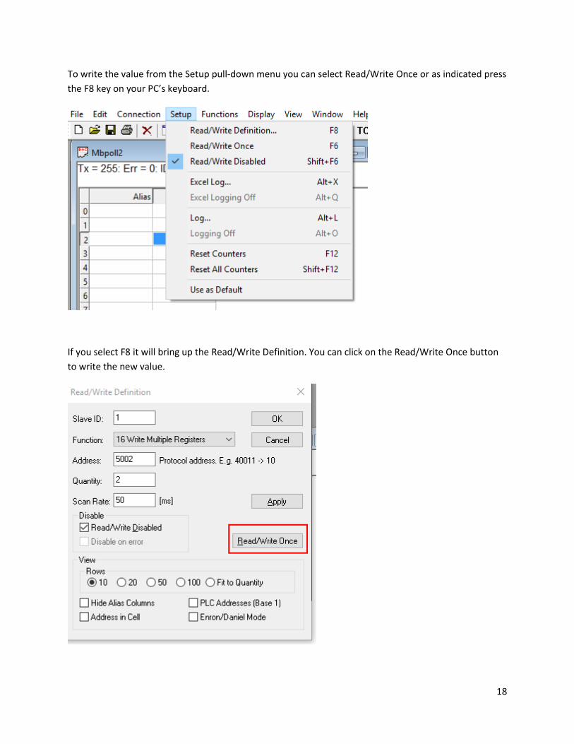
To write the value from the Setup pull-down menu you can select Read/Write Once or as indicated press
the F8 key on your PC’s keyboard.
If you select F8 it will bring up the Read/Write Definition. You can click on the Read/Write Once button
to write the new value.

19
Moving back to Workbench the Console in the Program screen of Workbench shows the current value
which is the value we wrote.

20
Next we will demonstrate the same methods but using KVB software.