albatros² boiler management unit lms14 user manual
TRANSCRIPT

Release 5 CC1U7471en 11.05.2012
Building Technologies DivisionInfrastructure & Cities Sector
Albatros² Boiler management unit LMS14... User Manual
The LMS14… and this User Manual are intended for use by OEMs which integrate the boiler management unit in their products.

2/588
Building Technologies Division User Manual LMS14… CC1U7471en Infrastructure & Cities Sector 11.05.2012

3/588
Building Technologies Division User Manual LMS14… CC1U7471en Infrastructure & Cities Sector Contents 11.05.2012
Contents
1 Summary .......................................................................................................15
1.1 Target group of users ....................................................................................16
1.2 Supplementary documentation......................................................................16
1.3 Product range summary ................................................................................17
1.3.1 Topology........................................................................................................17
1.3.2 Operating options ..........................................................................................18
2 Safety notes...................................................................................................19
2.1 Notes on product liability ...............................................................................19
2.1.1 Use of high-efficiency pumps ........................................................................20
2.1.2 High-voltage test............................................................................................20
2.2 Environmental compatibility...........................................................................21
2.3 Lifecycle.........................................................................................................21
2.4 Standards and certificates .............................................................................21
2.5 Typographical conventions............................................................................22
2.5.1 Safety notes...................................................................................................22
3 Mounting and installation...............................................................................23
3.1 Safety regulations..........................................................................................23
3.1.1 Electrical connection of ionization probe .......................................................23
3.2 Boiler management unit LMS14….................................................................24 Caution! .........................................................................................................24 Mounting (general information)......................................................................24 Ignition equipment .........................................................................................24 Connections and wiring .................................................................................25 Tests made by the customer .........................................................................25 Engineering ...................................................................................................25 Mounting location ..........................................................................................25
3.3 Basic diagram LMS14…................................................................................26
3.4 Basic unit LMS14… complete (Basic) ...........................................................27
3.4.1 Terminals of LMS14… complete (Basic) .......................................................28
3.4.2 Assignment of terminal X30...........................................................................29
3.4.3 List of terminals of LMS14… complete (Basic)..............................................30
3.5 Basic unit LMS14... complete (Medium)........................................................31
3.5.1 Terminals of LMS14… complete (Medium) ...................................................32
3.5.2 Assignment of terminal X30...........................................................................33
3.5.3 List of terminals of LMS14… complete (Medium)..........................................34
3.6 Basic unit LMS14... complete (Deluxe) .........................................................35
3.6.1 Terminals of LMS14… complete (Deluxe).....................................................36
3.6.2 Assignment of terminal X30...........................................................................37
3.6.3 List of terminals of LMS14… complete (Deluxe) ...........................................38
3.7 Cable AGU2.110x109....................................................................................39

4/588
Building Technologies Division User Manual LMS14… CC1U7471en Infrastructure & Cities Sector Contents 11.05.2012
3.8 Parameter stick AGU2.56xx109.....................................................................40
4 Commissioning ..............................................................................................41
4.1 Basic units......................................................................................................41
5 Handling.........................................................................................................42
5.1 Operation and display ....................................................................................42
5.2 Overview of settings.......................................................................................43
6 The settings in detail ....................................................................................114
6.1 Time of day and date ...................................................................................114
6.1.1 Summer-/wintertime changeover .................................................................114
6.2 RF link..........................................................................................................115
6.2.1 Binding .........................................................................................................115
6.2.2 List of wireless devices ................................................................................116
6.3 Time programs.............................................................................................117
6.3.1 Switching points ...........................................................................................117
6.3.2 Standard program........................................................................................117
6.4 Holidays .......................................................................................................118
6.5 Heating circuits ............................................................................................120
6.5.1 Operating mode ...........................................................................................120
6.5.2 Compensation variants ................................................................................122
6.5.3 Occupancy button (presence button)...........................................................124
6.5.4 Operating level.............................................................................................124
6.5.5 Setpoints ......................................................................................................125
6.5.6 Heating curve...............................................................................................126
6.5.7 ECO function................................................................................................129
6.5.8 Flow temperature setpoint limits ..................................................................132
6.5.9 Room thermostat .........................................................................................133 Functions with room thermostat...................................................................133 Flow temperature setpoint based on a fixed value ......................................134 Flow temperature setpoint in case of fixed value with adaption...................135 Flow temperature setpoint according to the heating curve ..........................136 Adaption with flow temperature setpoint according to the heating curve.....136
6.5.10 Delay heat request.......................................................................................137
6.5.11 Room model.................................................................................................139
6.5.12 Room influence ............................................................................................140 Compensation variants ................................................................................140
6.5.13 Room temperature control and limitation .....................................................142
6.5.14 Heating limit room controller ........................................................................143
6.5.15 Boost heating ...............................................................................................144
6.5.16 Quick setback ..............................................................................................145
6.5.17 Optimum start/stop control...........................................................................147
6.5.18 Heating up gradient room model..................................................................148
6.5.19 Raising the Reduced setpoint ......................................................................149

5/588
Building Technologies Division User Manual LMS14… CC1U7471en Infrastructure & Cities Sector Contents 11.05.2012
6.5.20 Continuous pump operation ........................................................................151
6.5.21 Frost protection for the room .......................................................................152
6.5.22 Frost protection for the heating circuit in Heating mode ..............................152
6.5.23 Overtemperature protection for the pump heating circuit ............................153
6.5.24 Locking signals ............................................................................................154 Critical locking signals .................................................................................154 Uncritical locking signals .............................................................................154
6.5.25 Forced signals .............................................................................................154
6.5.26 Overtemperature protection for the mixing heating circuit...........................154
6.5.27 Pulse lock ....................................................................................................155
6.5.28 Flow temperature alarm...............................................................................155
6.5.29 Locking signals ............................................................................................156
6.5.30 Forced signals .............................................................................................156
6.5.31 Mixing valve control .....................................................................................157
6.5.32 Floor curing function ....................................................................................159
6.5.33 Forced signal and locking signal .................................................................162
6.5.34 Buffer storage tank/primary controller .........................................................162
6.5.35 Speed-controlled pump ...............................................................................163
6.5.36 Operating level changeover via input H.......................................................165
6.5.37 Operating mode changeover via input H .....................................................165
6.5.38 Behavior in the case of burner cycling.........................................................166
6.5.39 2-speed heating circuit pump ......................................................................166
6.5.40 2-speed boiler pump....................................................................................167
6.6 Cooling circuit 1 ...........................................................................................168
6.6.1 Operating mode...........................................................................................168
6.6.2 Setpoints......................................................................................................168
6.6.3 Room temperature limitation .......................................................................169
6.7 DHW heating ...............................................................................................170
6.7.1 DHW mode ..................................................................................................171
6.7.2 Setpoints......................................................................................................172
6.7.3 Holiday program ..........................................................................................173
6.7.4 DHW release ...............................................................................................174
6.7.5 Priority .........................................................................................................176
6.7.6 Locking signals ............................................................................................176
6.7.7 Forced signals .............................................................................................177
6.7.8 Pump overrun ..............................................................................................177
6.7.9 Legionella function.......................................................................................178
6.7.10 Circulating pump..........................................................................................181
6.7.11 Frost protection for the circulation pipe .......................................................182
6.7.12 Operating mode changeover via input H .....................................................183
6.8 Consumer circuit and swimming pool circuit ...............................................184
6.9 Swimming pool ............................................................................................185
6.9.1 Setpoints......................................................................................................185

6/588
Building Technologies Division User Manual LMS14… CC1U7471en Infrastructure & Cities Sector Contents 11.05.2012
6.9.2 Priority..........................................................................................................185
6.9.3 Overtemperature protection .........................................................................186
6.9.4 Plant hydraulics............................................................................................186
6.10 Primary controller/system pump ..................................................................187
6.10.1 Limitations of the flow temperature setpoint ................................................187
6.10.2 Mixing valve control .....................................................................................188
6.10.3 Plant hydraulics............................................................................................189
6.11 Boiler............................................................................................................190
6.11.1 Release threshold Outside temperature ......................................................190
6.11.2 Full charging of buffer storage tank .............................................................190
6.11.3 Setpoints ......................................................................................................191
6.11.4 Setpoint manual control ...............................................................................193
6.11.5 Frost protection for the boiler .......................................................................194
6.11.6 PID control algorithm ...................................................................................195
6.11.7 Boiler/burner control.....................................................................................196
6.11.8 Overtemperature protection .........................................................................197
6.11.9 Minimum limitation of boiler temperature .....................................................198
6.11.10 Minimum limitation of return temperature ....................................................200
6.11.11 Boiler pump..................................................................................................201
6.11.12 Electronic temperature controller .................................................................202
6.11.13 Limitation of boiler temperature increase.....................................................203
6.11.14 Speed control...............................................................................................205
6.11.15 Output data ..................................................................................................211
6.11.16 Fan...............................................................................................................212
6.11.17 Control of the boiler/burner ..........................................................................214
6.11.18 Dynamic switching differentials....................................................................216
6.11.19 Delay heat request special operation...........................................................220
6.11.20 Flue gas supervision ....................................................................................221
6.11.21 Static pressure supervision..........................................................................224 Basics of static supervision..........................................................................224
6.11.22 Dynamic pressure supervision.....................................................................226 Basics of dynamic supervision.....................................................................227
6.11.23 Water pressure sensor.................................................................................230
6.11.24 Filling/flow supervision .................................................................................232
6.11.25 Quick shutdown of burner ............................................................................234
6.11.26 Limitation of output.......................................................................................235
6.11.27 Electronic limit thermostat............................................................................237
6.11.28 Electronic safety limit thermostat (SLT) .......................................................238 Basics of electronic safety limit thermostat (SLT) ........................................238 Error handling ..............................................................................................238
6.11.29 Deaeration function......................................................................................243
6.11.30 Input configuration dynamic pressure supervision.......................................246
6.11.31 Input configuration flow supervision.............................................................246

7/588
Building Technologies Division User Manual LMS14… CC1U7471en Infrastructure & Cities Sector Contents 11.05.2012
6.11.32 Additional settings for static pressure supervision.......................................247
6.11.33 Additional settings for dynamic pressure supervision..................................248
6.12 Special boiler functions................................................................................249
6.12.1 Change of operating mode ..........................................................................249
6.12.2 Loading the setpoint/actual value ................................................................249
6.12.3 Automatic heat generation lock ...................................................................250
6.12.4 Manual heat generation lock .......................................................................250
6.12.5 Generation of common flow temperature setpoint.......................................251
6.12.6 Generation of boiler temperature setpoint ...................................................251
6.12.7 Boiler control................................................................................................252
6.12.8 Heat output limits.........................................................................................253
6.12.9 2-position controller .....................................................................................253
6.12.10 Protective boiler startup...............................................................................254
6.12.11 Keeping the boiler hot..................................................................................256
6.12.12 Alternative setting of output .........................................................................256
6.13 Cascaded systems ......................................................................................257
6.13.1 Addressing devices .....................................................................................257
6.13.2 Cascade master ..........................................................................................258
6.13.3 Operating mode...........................................................................................259
6.13.4 Control .........................................................................................................260
6.13.5 Boiler sequence...........................................................................................261
6.13.6 Minimum limitation of return temperature ....................................................263
6.13.7 Supervision of temperature differential........................................................264
6.14 Extra heat source ........................................................................................264
6.15 Solar ............................................................................................................265
6.15.1 General........................................................................................................265
6.15.2 Sensors .......................................................................................................266 Sensor selection for the DHW storage tank ................................................266 Sensor selection for the buffer storage tank................................................266 Display of actual values...............................................................................267 Display of minimum and maximum values ..................................................267 Collector sensor measured value correction ...............................................267
6.15.3 Charging controller (dT)...............................................................................268
6.15.4 Maximum charging temperature, maximum safety temperature .................270
6.15.5 Priority .........................................................................................................271
6.15.6 Collector start function.................................................................................273
6.15.7 Frost protection for the collector ..................................................................275
6.15.8 Overtemperture protection for the collector .................................................276
6.15.9 Recooling.....................................................................................................278
6.15.10 Evaporation temperature of medium ...........................................................280
6.15.11 Speed control ..............................................................................................281
6.15.12 Yield measurement......................................................................................282
6.15.13 Hours run.....................................................................................................282
6.16 Solid fuel boiler ............................................................................................283

8/588
Building Technologies Division User Manual LMS14… CC1U7471en Infrastructure & Cities Sector Contents 11.05.2012
6.16.1 General ........................................................................................................283
6.16.2 Operating mode ...........................................................................................284
6.16.3 Setpoints ......................................................................................................286
6.16.4 Control of the boiler/burner ..........................................................................287 DHW storage tank........................................................................................288 Buffer storage tank.......................................................................................289 Flow temperature setpoint ...........................................................................289 Minimum setpoint.........................................................................................290
6.16.5 Overtemperature protection .........................................................................291
6.16.6 Frost protection ............................................................................................292
6.16.7 Frost protection for the solid fuel boiler........................................................293
6.16.8 Configuration errors .....................................................................................293
6.16.9 Sensor error .................................................................................................293 Boiler sensor ................................................................................................293 Comparative sensor.....................................................................................293
6.17 Buffer storage tank.......................................................................................294
6.17.1 Release/control of heat source ....................................................................294
6.17.2 Automatic locks............................................................................................294
6.17.3 Charging solar/solid fuel boiler.....................................................................296
6.17.4 Recooling .....................................................................................................297
6.17.5 Plant hydraulics............................................................................................297
6.17.6 Return diversion...........................................................................................298
6.17.7 Partial charging ............................................................................................299
6.17.8 Full charging ................................................................................................300
6.17.9 Frost protection for the buffer in Heating mode ...........................................300
6.17.10 Heat transfer to the DHW storage tank........................................................301 Heat transfer via charging pump Q3............................................................301 Heat transfer via transfer pump Q11............................................................301 Time of heat transfer....................................................................................301 Transfer sensors and temperature level ......................................................302 Heat transfer in connection with combi storage tanks .................................302
6.18 DHW storage tank........................................................................................303
6.18.1 Types of heat request ..................................................................................303
6.18.2 DHW charging with one sensor ...................................................................303
6.18.3 DHW charging with 2 sensors......................................................................304
6.18.4 DHW charging with thermostat ....................................................................304
6.18.5 Release........................................................................................................305
6.18.6 Charging control...........................................................................................307
6.18.7 Limitation of charging time ...........................................................................308
6.18.8 Charging pump/diverting valve ....................................................................308
6.18.9 Discharging protection .................................................................................309
6.18.10 Overtemperature protection .........................................................................310
6.18.11 Frost protection for the DHW storage tank ..................................................311
6.18.12 Recooling .....................................................................................................312
6.18.13 Electric immersion heater ............................................................................313

9/588
Building Technologies Division User Manual LMS14… CC1U7471en Infrastructure & Cities Sector Contents 11.05.2012
6.18.14 DHW push ...................................................................................................316
6.18.15 Excess heat draw ........................................................................................318
6.18.16 Plant hydraulics ...........................................................................................318
6.18.17 Speed-controlled pump ...............................................................................319
6.18.18 Heat transfer................................................................................................321
6.18.19 Stratification storage tank/intermediate circuit.............................................322 Variant: ........................................................................................................322
6.19 Storage tank systems ..................................................................................324
6.19.1 Control of storage tank with sensor .............................................................324
6.20 Stratification storage tank ............................................................................326
6.20.1 Stratification storage tank with control to the boiler temperature flow .........327
6.20.1.1. Full charging of stratification storage tank ...................................................329
6.20.1.2. Recharging the stratification storage tank ...................................................330
6.20.2 Stratification storage tank with control to the DHW charging temperature via setpoint compensation.................................................................................................331
6.20.2.1. Full charging of stratification storage tank ...................................................333
6.20.2.2. Recharging the stratification storage tank ...................................................336
6.20.3 Stratification storage tank with direct control to the DHW charging temperature .................................................................................................................337
6.20.3.1. Full charging of stratification storage tank ...................................................338
6.20.3.2. Recharging the stratification storage tank ...................................................340
6.21 Instantaneous water heater .........................................................................341
6.21.1 Control .........................................................................................................341
6.21.2 DHW consumption (flow).............................................................................341
6.21.3 DHW consumption (gradient) ......................................................................342
6.21.4 Keep hot function.........................................................................................343
6.21.5 Times...........................................................................................................344
6.21.6 Overrun........................................................................................................344
6.21.7 Speed-controlled pump ...............................................................................345
6.21.8 Configuration ...............................................................................................346 Basics of instantaneous water heater (function)..........................................346 Instantaneous water heater with primary heat exchanger...........................350 Instantaneous water heater with secondary heat exchanger and water outlet sensor..........................................................................................................351 Instantaneous water heater with secondary heat exchanger without water outlet sensor (aqua booster)........................................................................354 Instantaneous water heater with secondary heat exchanger, DHW outlet and inlet sensor (aqua-booster)..........................................................................355
6.21.9 Setpoint readjustment..................................................................................359 Basics of setpoint readjustment...................................................................359
6.22 Configuration ...............................................................................................360
6.22.1 Manual setting/adaption of partial diagrams................................................363
6.22.2 Heating circuits/cooling circuit .....................................................................363
6.22.3 DHW storage tank .......................................................................................364
6.22.4 DHW separate circuit...................................................................................367

10/588
Building Technologies Division User Manual LMS14… CC1U7471en Infrastructure & Cities Sector Contents 11.05.2012
6.22.5 Boiler............................................................................................................370
6.22.6 Boiler pump..................................................................................................370 Basics of boiler pump...................................................................................371
6.22.7 Solar.............................................................................................................376
6.22.8 Combi storage tanks ....................................................................................377
6.22.9 Relay outputs QX.........................................................................................378
6.22.10 Sensor inputs BX .........................................................................................384
6.22.11 Inputs H1/H3/H4/H5/H6/H7..........................................................................386
6.22.12 Extension modules.......................................................................................396
6.22.13 EX extension modules 1/2/3 ........................................................................398
6.22.14 QX extension modules 1/2/3........................................................................400
6.22.15 BX extension modules .................................................................................405
6.22.16 H2 extension modules 1/2/3 ........................................................................407
6.22.17 PWM output P1............................................................................................415
6.22.18 Types of sensors/readjustments ..................................................................416
6.22.19 Building model .............................................................................................417 Current, composite and attenuated outside temperature.............................417
6.22.20 Setpoint compensation ................................................................................419 Setpoint compensation ................................................................................419
6.22.21 Frost protection for the plant ........................................................................420
6.22.22 Control of flue gas damper...........................................................................421
6.22.23 Pump/valve kick ...........................................................................................421
6.22.24 Pressure measurements H1, H2 and H3 .....................................................422
6.22.25 Saving the sensors ......................................................................................424
6.22.26 Plant diagrams.............................................................................................439
6.22.27 Device data ..................................................................................................443
6.23 LPB system..................................................................................................445
6.23.1 Address/power supply..................................................................................445
6.23.2 Errors/maintenance/alarm............................................................................446
6.23.3 Central functions ..........................................................................................447 Central summer changeover (LPB) .............................................................447 Central operating mode changeover via LPB ..............................................447
6.23.4 Clock ............................................................................................................452
6.23.5 Outside temperature ....................................................................................452
6.24 Faults ...........................................................................................................453
6.24.1 Message ......................................................................................................453
6.24.2 Acknowledgements......................................................................................453
6.24.3 Error message functions ..............................................................................454
6.24.4 History..........................................................................................................456
6.25 Maintenance/special mode ..........................................................................457
6.25.1 Maintenance functions .................................................................................457
6.26 Special operating modes .............................................................................458
6.27 Parameter stick AGU2.56... .........................................................................464
6.27.1 Wrong use and risks ....................................................................................464

11/588
Building Technologies Division User Manual LMS14… CC1U7471en Infrastructure & Cities Sector Contents 11.05.2012
Introduction..................................................................................................464
6.27.2 Checks made by the LMS14... ....................................................................464
6.27.3 Examples of potential risks..........................................................................465 All possible checks canceled.......................................................................465
6.27.4 Reducing potential risks ..............................................................................465 OEM parameter set group number and OEM boiler type ............................465
6.27.5 Spare part business.....................................................................................466
6.27.6 General notes on risks and problems..........................................................467 Restrictions..................................................................................................467 Human failure ..............................................................................................467 Safety-related parameters ...........................................................................467
6.27.7 Operation via the boiler ...............................................................................468
6.27.8 Parameter setting state ...............................................................................472
6.27.9 Conditions for the transfer of data between LMS14... and parameter stick.473 OnlineDDGroupNo ......................................................................................473 ParaSatzNr ..................................................................................................473 Display name...............................................................................................474
6.28 Input/output test...........................................................................................475
6.28.1 Output test relay ..........................................................................................476
6.28.2 Input test sensors ........................................................................................478
6.28.3 Input test H1/H2/H3/H4/H5/H6/H7...............................................................479
6.28.4 Input test EX (extension modules)...............................................................479
6.29 Operating state ............................................................................................480
6.29.1 Messages ....................................................................................................480
6.30 Diagnostics of cascaded system .................................................................485
6.31 Diagnostics of heat sources ........................................................................486
6.31.1 Process values ............................................................................................486
6.32 Diagnostics of consumers ...........................................................................486
6.33 Burner control ..............................................................................................487
6.33.1 Prepurging ...................................................................................................487
6.33.2 Ignition .........................................................................................................488
6.33.3 Operation.....................................................................................................489
6.33.4 Postpurging .................................................................................................490
6.33.5 Configuration ...............................................................................................491
6.33.6 Fan control...................................................................................................494
6.33.7 Chimney drying............................................................................................495
6.33.8 Setpoint filter for fan speed control..............................................................496
6.34 Program sequence of burner control (function) ...........................................503
6.34.1 Program selection........................................................................................503
6.34.2 Forced intermittent operation.......................................................................503
6.34.3 Burner control program................................................................................503
6.34.4 Burner capacities.........................................................................................504
6.34.5 Sequence diagram for burner capacities ≤120 kW......................................505
6.34.6 Sequence diagram for burner capacities ≥120 kW......................................506

12/588
Building Technologies Division User Manual LMS14… CC1U7471en Infrastructure & Cities Sector Contents 11.05.2012
Description of sequence diagrams...............................................................509 Program times of sequence diagrams .........................................................509
6.34.7 Repetition counter........................................................................................510 Loss of flame during operation.....................................................................510 No flame on completion of safety time.........................................................510
6.34.8 Description of sequence diagrams...............................................................511 Standby........................................................................................................511 Startup .........................................................................................................511 Operation .....................................................................................................512 Shutdown .....................................................................................................513 Home run .....................................................................................................513 Error .............................................................................................................514 Special cases (deviations) ...........................................................................515
6.34.9 Fan speed control ........................................................................................517
6.34.10 Filter for fan speed setpoint (OEM)..............................................................518
6.35 PWM limitation .............................................................................................522
6.35.1 Supervising air supply by monitoring current fan speed ..............................522 Limitation of PWM........................................................................................523
6.36 Chimney drying ............................................................................................525
6.37 Fan parameters settable as load values via QAA75…/AVS37… ................526
6.37.1 Limitation of ionization current .....................................................................533
6.37.2 Ionization current maintenance....................................................................533
6.38 Modulating pump .........................................................................................534
6.38.1 Modulation of heating circuit pump ..............................................................534 Operating level.............................................................................................534 Heating curve...............................................................................................534 Weather-compensated.................................................................................534 Room-compensated.....................................................................................535
6.38.2 Behavior when burner cycles.......................................................................536
6.38.3 Limitation of boiler temperature differential..................................................537 Fundamentals ..............................................................................................537 Purpose of limiting the boiler’s temperature differential ...............................537
6.38.4 Conditions for limiting the boiler’s temperature differential ..........................538
6.38.5 Limitation dependent on pump modulation ..................................................538
6.38.6 Limitation to the maximum differential .........................................................539
6.38.7 Limitation to the nominal differential ............................................................540
6.39 List of displays .............................................................................................540
6.39.1 Error code list...............................................................................................541
6.39.2 Maintenance code........................................................................................545
6.40 Lockout/local reset .......................................................................................545
6.40.1 Lockout ........................................................................................................545
6.40.2 Local reset via the reset button....................................................................545
6.41 Remote reset ...............................................................................................546
6.41.1 Additional activation of remote reset capability............................................546
6.41.2 Restrictions in connection with remote reset ...............................................546
6.42 Production....................................................................................................547
6.42.1 Monitoring mains voltage/mains frequency..................................................549

13/588
Building Technologies Division User Manual LMS14… CC1U7471en Infrastructure & Cities Sector Contents 11.05.2012
7 Plant diagrams.............................................................................................550
7.1 Basic diagrams ............................................................................................550
7.2 Extra functions in general ............................................................................551 Solar ............................................................................................................551 Boiler ...........................................................................................................552 DHW storage tank (DHW) ...........................................................................553 Buffer storage tank ......................................................................................554 Heat converter .............................................................................................554
7.3 Extra functions with mixing group or extension module AVS75.39x…/AGU2.550... ..........................................................................................555
8 Technical data .............................................................................................558
8.1 LMS14… basic unit .....................................................................................558
8.1.1 General data................................................................................................558
8.1.2 Environmental conditions ............................................................................558
8.1.3 Electrical connections..................................................................................559
8.1.4 Low-voltage side..........................................................................................561
8.1.4.1. Inputs B7/BX4..............................................................................................561
8.1.4.2. Inputs B3/B38 ..............................................................................................561
8.1.4.3. Inputs BX1/BX2/BX3 ...................................................................................561
8.1.4.4. Input B9 .......................................................................................................561
8.1.4.5. Input H1 .......................................................................................................562
8.1.4.6. Input H3 .......................................................................................................562
8.1.4.7. Input H4 .......................................................................................................562
8.1.4.8. Input H5 .......................................................................................................563
8.1.4.9. Input H6 .......................................................................................................563
8.1.4.10. Input H7 .......................................................................................................563
8.1.4.11. Input for reset (EK) ......................................................................................563
8.1.5 PWM fan/Hall connection facility .................................................................564
8.1.6 PWM pump connection ...............................................................................564
8.1.7 Control of diverting valve .............................................................................564
8.1.8 BSB users....................................................................................................565
8.1.9 Cross-sectional area sensors ......................................................................565
8.2 Parameter stick AGU2.56xx109 ..................................................................566
8.3 Sensor characteristics .................................................................................567
8.3.1 NTC 1k ........................................................................................................567
8.3.2 NTC 10k ......................................................................................................568
8.3.3 Pt1000 .........................................................................................................568
8.3.4 NTC 20k ......................................................................................................569
9 List of figures ...............................................................................................571

14/588
Building Technologies Division User Manual LMS14... CC1U7471en Infrastructure & Cities Sector 1 Summary 11.05.2012

15/588
Building Technologies Division User Manual LMS14... CC1U7471en Infrastructure & Cities Sector 1 Summary 11.05.2012
1 Summary The present User Manual describes handling and configuration of the following products for OEMs:
Product no. (ASN)
Description Documentation no.
CC1E7471
CC1U7471 LMS14... Boiler management unit
CC1U7472
AGU2.560... Parameter stick für LMS..., can be read out CC1U7471
AGU2.561... Parameter stick for LMS..., writable CC1U7471
AGU2.563... Parameter stick for direct programming of the LMS... CC1U7471
AGU2.564... Parameter stick for spare part programming of the LMS... CC1U7471
OCI345.06/101 LPB ClipIn CC1U2355xx_04 For more information about accessories, refer to the following documents:
Product no. (ASN)
Description Documentation no.
LMS15... Boiler management unit CC1U7472
Product range Product range overview Albatros² CE1Q2359
Subdiagrams Albatros2 Hydraulic subdiagrams and extra functions CE1U2359
AGU2.550... Extension ClipIn for LMS... CC1N7492
AGU2.551... Extension ClipIn for PWM (DC 0...10 V) CC1N7493
AGU3.6... Gas/air mixer CC1N7211
AGU3.7... Gas/air mixer CC1N7214
AVS13.399... Wireless outside sensor CE1U2354
AVS14.390... Wireless repeater CE1U2354
AVS37.294... Operating unit (Clear-text) CE1U2353
AVS37.390... Operating unit (Basic) CE1U2358
AVS71.390... Wireless module CE1U2354
AVS75.390... Extension module CE1U2353
AVS75.391... Extension module CE1U2354
QAA55.110... Room unit basic CE1U2353
QAA75.610... Room unit wire CE1U2353
QAA75.611... Room unit wire, with backlit display CE1U2353
QAA78.610... Room unit wireless CE1U2353
QAC34/101 Outside sensor NTC 1k CC1Q1701
QAD36/101 Strap-on temperature sensor NTC 10k CC1Q1808
QAZ36.522/109 Immersion temperature sensor NTC 10k CC1Q1843
QAZ36.526/109 Immersion temperature sensor NTC 10k CC1Q1843
OCI430... Interface module for PC-LMS... connection CC1N7635
OCI700 Service tool CC1E5655
TQG42... Ignition module, combined with connection line for LMS14..., suitable for VGU smart gas valves
CC1N7630

16/588
Building Technologies Division User Manual LMS14... CC1U7471en Infrastructure & Cities Sector 1 Summary 11.05.2012
Product no. (ASN)
Description Documentation no.
VGU7xS... Combination gas valves CC1N7668
VGU8xS... Combination gas valves CC1N7668
ACS420 Software for OCI430... ---
ACS432 Parameter stick manager CC1J7474
ACS435 Setup manager CC1J7471
ACS700 Remote supervision software/parameterization software for OCI700 Software CD LMS14... are digital boiler management units (BMUs) for use with gas-fired appliances equipped with premix burners. They are used for startup, control and supervision of premix burners with capacities from <10 kW to 1 MW in intermittent operation with direct ignition of the main flame. The OEM must make certain that the LMS14… are suited for the application in question. The LMS14... provide all supervisory and control functions required for burner operation, space heating and DHW heating. They also offer modular system extensions in the form of integrated communication interfaces. Output modulation is performed via a PWM-controlled fan with pneumatic gas-air ratio control.
1.1 Target group of users Target group of users are OEMs
1.2 Supplementary documentation
Environmental Declaration LMS... .......................................................................... E7471
Data Sheet LMS… ..................................................................................................N7471
Product range overview LMS… ............................................................................Q7471
Type summary Albatros².......................................................................................Q2359
Albatros2 Hydraulic Partial Diagrams and Extra Functions.................................... P2359
LMS14…

17/588
Building Technologies Division User Manual LMS14... CC1U7471en Infrastructure & Cities Sector 1 Summary 11.05.2012
1.3 Product range summary
1.3.1 Topology Remote
Service tool
Mobile, SMS, Pager , Fax , WEB
TelefonNetwork
TelefonSMS
OCI611OCI7...
ACS700
BSB : Boiler System Bus
Service Unit(RU)HMI
HMI (RU)
Basic UnitLMS...
Extensionmod. AVS75…
(max. 3)
BSB-W
LPB : Local Process Bus
Basic UnitLMS... / RVS...
LPB
Service tool
OCI430
ACS420
7471z01e/1210
OCI345...
Room Unit
Figure 1: Product range summary – wired
Remote
Service tool
Mobile , SMS, Pager , Fax , WEB
TelefonNetwork
TelefonSMS
OCI611OCI700
RF Modul
ACS700
BSB : Boiler System Bus
Room Unit
RF Repeater
RF Toutside
BSB-RF
Service Unit(RU)
HMI(RU)
Wireless Wireless Wireless
Basic UnitLMS...
Extensionmod. AVS75...
(max. 3)
BSB -W
LPB : Local Process Bus
Basic UnitLMS... / RVS...
LPB
Service tool
OCI430
ACS420
7471z02e/1210
OCI345...
Figure 2: Product range summary – wireless
Wired
Wireless
18/588
Building Technologies Division User Manual LMS14... CC1U7471en Infrastructure & Cities Sector 1 Summary 11.05.2012
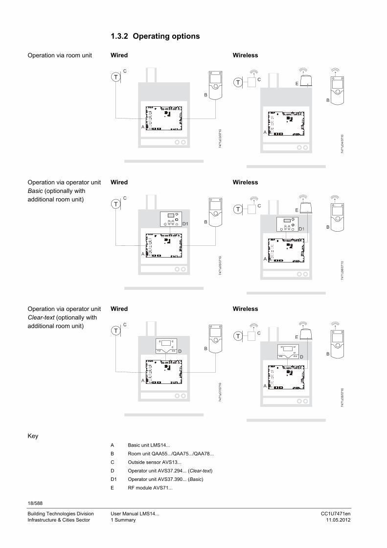
1.3.2 Operating options Wired Wireless
A
T
A
T
Wired Wireless
A
T
Reset
+
A
T
Reset
+
Wired Wireless
A
T
D
A
T
D
Key
A Basic unit LMS14...
B Room unit QAA55.../QAA75.../QAA78...
C Outside sensor AVS13...
D Operator unit AVS37.294... (Clear-text)
D1 Operator unit AVS37.390... (Basic)
E RF module AVS71...
Operation via room unit
Operation via operator unit Basic (optionally with additional room unit)
Operation via operator unit Clear-text (optionally with additional room unit)

19/588
Building Technologies Division User Manual LMS14... CC1U7471en Infrastructure & Cities Sector 2 Safety notes 11.05.2012
2 Safety notes 2.1 Notes on product liability The LMS14… may only be used in building services plant and only in compliance
with the applications covered by this document When employing the products, all requirements specified in chapters Handling and
Technical data must be satisfied Local safety regulations (installation, etc.) must be complied with The units must not be opened. If not observed, warranty by Siemens becomes void
Danger! Do not open, interfere with or modify the units! All activities (mounting, installation, service work, etc.) must be performed by
qualified personnel Before performing any work in the connection area of the LMS14…, disconnect the
unit from mains supply (all-polar disconnection). Ensure that the plant cannot be inadvertently switched on again and that it is indeed dead. If not disconnected, there is a risk of electric shock
Ensure protection against electric shock by providing adequate protection for the unit’s terminals
After any kind of activity (mounting, installation, service work, etc.), check to ensure that wiring is in an orderly state, that all safety functions are performed correctly and that the parameter settings are correct
Fall or shock can adversely affect the safety functions. Such units must not be put into operation, even if they do not exhibit any damage
AC 230 V terminals that are not used must be protected by dummy plugs fitted by the burner manufacturer
Never connect or disconnect the stepper motors (WX1 connected to X16 or X16a) when live. If not observed, the built-in driver stage can be damaged
Siemens will not assume liability for damage resulting from unauthorized interference! If fuses inside the LMS15… are blown, the unit must be returned to Siemens. The mains fuse (FB01/FB02) may be replaced once. Since overcurrents can damage relays, a plant safety check must be made. Electromagnetic emissions must be checked on an application-specific basis! The choice of applications and scope of functions covered by this User Manual shall serve as a guideline. The correct operation of the plant must be checked and proven by function tests made on the heating appliance and the relevant plant!
Danger! At the OEM’s request, the quick connector for the mechanical STB (SLT = safety limit thermostat) on the printed circuit board can be bridged ex factory. In that case, the mechanical SLT would be deactivated. When using a mechanical SLT, the resistor must always be removed. LMS14... with different type numbers must never be mixed up.

20/588
Building Technologies Division User Manual LMS14... CC1U7471en Infrastructure & Cities Sector 2 Safety notes 11.05.2012
2.1.1 Use of high-efficiency pumps When using high-efficiency pumps or pumps with integrated electronics, the resulting switch-on currents can adversely affect the relays’ service life. For this reason, use of these types of pump is permitted only if authorized in writing by Siemens.
2.1.2 High-voltage test
Caution! When making 100% inspections to DIN EN 60335-1, Addendum A, only AC voltage may be applied. If tests are conducted with DC voltage, the LMS14... might be damaged.

21/588
Building Technologies Division User Manual LMS14... CC1U7471en Infrastructure & Cities Sector 2 Safety notes 11.05.2012
2.2 Environmental compatibility The units contain electrical and electronic components and must not be disposed of together with domestic waste. Local and currently valid legislation must be complied with!
2.3 Lifecycle The LMS14… have a designed lifetime* of 250,000 burner startup cycles which, under normal operating conditions in Heating mode, correspond to approx. 10 years of usage (starting from the production date indicated on the type field). This lifetime is based on the endurance tests specified in standard EN 298 and the table containing the relevant test documentation as published by the European Association of Component Manufacturers (Afecor) (www.afecor.org). The designed lifetime is based on usage of the LMS14… as specified in the manufacturer’s Data Sheet and User Manual. After reaching the designed lifetime in terms of the number of burner startup cycles, or the respective time of usage, the LMS14… are to be replaced by authorized personnel. * The designed lifetime is not identical with the warranty time specified in the Terms of Delivery
2.4 Standards and certificates
Conformity to EEC directives - Electromagnetic compatibility EMC (immunity) - Directive for gas-fired appliances - Low-voltage directive
2004/108/EC 2009/142/EC 2006/95/EC
ISO 9001: 2008 Cert. 00739
ISO 14001: 2004 Cert. 38233
Identification code to EN 298 chapter 4: F M C L B N
Disposal

22/588
Building Technologies Division User Manual LMS14... CC1U7471en Infrastructure & Cities Sector 2 Safety notes 11.05.2012
2.5 Typographical conventions 2.5.1 Safety notes This User Manual contains instructions which must be observed to ensure your personal safety and to prevent damage to equipment and property. The instructions and notes are highlighted by warning triangles, arrows or information symbols and are presented as follows, depending on the hazard level:
Danger means that death, severe personal injury or substantial
property damage will occur if adequate precautionary measures are not taken.
Warning means that death, severe personal injury or substantial
property damage can occur if adequate precautionary measures are not taken.
Caution means that minor personal injury or property damage
can occur if adequate precautionary measures are not taken.
Note draws your attention to important information on the product, on product handling, or to a special part of the documentation.
Reference refers to further information given in other pieces of
documentation or in chapters of this document. Only qualified personnel are allowed to install and operate the equipment. Qualified personnel in the context of the safety-related notes contained in this document are persons who are authorized to commission, ground and tag devices, systems and electrical circuits in compliance with established safety practices and standards. Note the following: The LMS14… may only be used on applications covered by the technical description. The use of unsuitable or incorrectly installed accessories can lead to personal injury or damage to property. When using the unit in connection with third-party products or components, following must be noted: - The technical data of the LMS14… must be observed; in addition to static data, consideration must be given to dynamic data, such as switch-on and switch-off currents, surge currents, etc. - EMC-specific properties or retroactive effects can adversely affect the unit’s life and reliability and must be checked by the customer - The OEM as the system integrator must ensure compliance with the relevant regulations and make certain the correct fuses are used - Siemens assumes no responsibility for the system The products can only function correctly and safely if shipped, stored, set up and installed correctly, and operated and maintained as specified.
Qualified personnel
Correct use

23/588
Building Technologies Division User Manual LMS14... CC1U7471en Infrastructure & Cities Sector 3 Mounting and installation 11.05.2012
3 Mounting and installation 3.1 Safety regulations Prior to installation, disconnect power The low-voltage and mains voltage terminals are arranged on different sides of the
unit When making the wiring, the requirements of safety class II must be satisfied
Warning! Never run ionization probe cable and mains cables in the same trunk.
Warning! When making the wiring, the AC 230 V section must be strictly segregated
from the extra low-voltage section, thus ensuring protection against electric shock and electromagnetic interference
In connection with the (safety) limit thermostat, observe the safety-related notes given in chapter Electronic safety limit thermostat (SLT)
Make certain that spliced individual wires cannot touch neighboring terminals. Fit suitable ferrules
Always run the high-voltage ignition cables separate from the unit and other cables while observing the greatest possible distances
Danger! Compliance with DIN EN 60 335 and DIN EN 60730-2-5 must be ensured The electrical wiring inside the boiler must conform to national and local
regulations Degree of protection IP40 as per DIN EN 60529 for burner controls must be
ensured by the burner or boiler manufacturer through correct installation of the LMS14...
3.1.1 Electrical connection of ionization probe It is important to achieve practically disturbance- and loss-free signal transmission: Never run the ionization probe cable together with other cables
- Line capacitance reduces the magnitude of the flame signal - Use a separate cable
Observe the permissible length of the ionization probe cable (refer to chapter Technical data in the relevant pieces of documentation)
Locate ignition electrode and ionization probe such that the ignition spark cannot arc over to the ionization probe (risk of electric shock)
Locate the ionization probe and its connections such that adequate protection against direct or indirect contact with active parts is ensured in every unfavorable position allowed under correct usage conditions. If not observed, there is a risk of electric shock
Electrical installation

24/588
Building Technologies Division User Manual LMS14... CC1U7471en Infrastructure & Cities Sector 3 Mounting and installation 11.05.2012
3.2 Boiler management unit LMS14… When mounting the PCB on a metal plate, the clearance between the lower edge of the PCB and the metal plate must be a minimum of 12 mm (as per DIN EN 60335 minimum 8 mm air and creepage path to the end of the wires or the solder fillets). - Spacers must be made of electrically non-conductive material! - When using metal screws for fixing, the head diameter must be 7.5 mm! - If 2 metal screws are screwed into a spacer from both sides, an air path of 8 mm must be observed or solid insulation of 2 mm must be provided (as per DIN EN 60335)!
Caution! Mounting (general information) Currently valid national safety regulations must be complied with! Inside the boiler, the unit must be fitted in a housing ensuring degree of
protection IP40 as a minimum requirement Depending on the location and environmental conditions, higher degrees of
protection may be required When mounted, the maximum permissible ambient temperature must never be
exceeded Condensation water must not drip on the LMS14… or enter the unit, neither in
operation nor when service work is carried out
Ignition equipment
Note! In terms of switching performance, any type of external ignition module used must be approved by Siemens!
Electric ignition sparks generate high-frequency energy which can adversely affects radio and television reception. The high-voltage cable running to the ignition electrode acts as a transmit antenna. For this reason, application-specific tests must be made to confirm that adequate distances are observed. High-frequency energy is also of capacitive and inductive nature, that is, not wire-bound. This must be taken into consideration when laying the cables. The ignition cable used must satisfy the technical requirements of the ignition module and should be run to the ignition electrode as directly as possible, with no loops in between. It must never be laid parallel or very close to other electrical cables.

25/588
Building Technologies Division User Manual LMS14... CC1U7471en Infrastructure & Cities Sector 3 Mounting and installation 11.05.2012
Connections and wiring
When making the wiring, ensure that the protective extra low-voltage side is strictly separated from other sections, thus providing protection against electric shock and making certain that EMC will not be adversely affected! The connectors’ predefined coding must be observed! Make the connections only when the components are disconnected from power! AC 230 V terminals that are not used must be covered by dummy plugs to ensure protection against electric shock! A multipole isolator is required to disconnect the unit from mains supply. For wiring the bus users, cables specified by Siemens are mandatory! External signal sources (air pressure switch, room thermostat, DHW flow switch, etc.) should have gold-plated silver contacts. Both ionization probe and ignition electrode must be protected against electric shock. Since the line to the ionization probe must be well insulated against ground, that line together with the ionization probe must be protected against condensation and very damp surroundings.
Warning! Connector X17 for the burner ground (FE – burner GND) must be connected as directly as possible to protective earth (PE) of the mains cable and to function earth X1 or X1a, pin 2, at the mains input of the LMS14... The burner’s housing must also be connected to the protective earth of the mains cable. The safety regulations for protective earth wiring must be complied with in all cases. Neutral point is the protective earth terminal of the mains cable. The way protective earth is wired has a considerable impact on whether the emission limits as per DIN EN 60335 are adhered to and on the unit’s EMC performance inside the boiler. The low-voltage ground of the LMS14... is connected to protective earth, but is classified as PELV since no protective function is required.
Tests made by the customer
If the boiler or burner manufacturer wants to make additional insulation and high-voltage tests, prior approval by Siemens is required!
Engineering
Air circulation around the LMS14… must be ensured, enabling the unit to dissipate the heat produced by its controller
The LMS14… is designed in compliance with the directives for safety class II and must be mounted in accordance with these directives
Power may be switched on only when the unit is completely mounted. Otherwise, there is a risk of electric shock at the terminals and through the cooling slots
The unit must not be exposed to drip water Mains cables must be run completely separate from low-voltage cables (sensors),
observing a minimum distance of 100 mm
Mounting location The LMS14… has been designed for mounting inside the burner or inside a control panel. Protection against electric shock must be ensured!

26/588
Building Technologies Division User Manual LMS14... CC1U7471en Infrastructure & Cities Sector 3 Mounting and installation 11.05.2012
3.3 Basic diagram LMS14…
7471a44e/0412 Figure 3: Basic diagram
The diagram shows the full scope of functions of the LMS… system. The actual functions are to be determined based on the respective execution/configuration.

27/588
Building Technologies Division User Manual LMS14... CC1U7471en Infrastructure & Cities Sector 3 Mounting and installation 11.05.2012
3.4 Basic unit LMS14… complete (Basic) Dimensions in mm
747
1m
20/
1209
Figure 4: Dimensions of basic unit complete (Basic)

28/588
Building Technologies Division User Manual LMS14... CC1U7471en Infrastructure & Cities Sector 3 Mounting and installation 11.05.2012
3.4.1 Terminals of LMS14… complete (Basic)
LED
Fla
me LE
D lo
cko
ut
Res
etId
ent
ifica
tion
por
t+1
2 V
CL+
GN
D
BS
B b
us r
oom
un
it
Res
et
OC
I34
5
Fan PWM
AG
U2
.56.
..
OC
I43
0
Ma
ins
sup
ply
7471
a40
e/0
811Ionization
Fuel valve
FE burner GND
Ignition module
BS
B b
us
roo
m u
nit
Figure 5: Terminals of LMS14… complete

29/588
Building Technologies Division User Manual LMS14... CC1U7471en Infrastructure & Cities Sector 3 Mounting and installation 11.05.2012
3.4.2 Assignment of terminal X30
7471m22e/0412
LED
flam
e
LED
lock
out
CL+
GN
D/C
L-
I =
2...
10 m
ALED
Rv
= e
xter
nal
Sta
te L
ED
s
Uex
t 12
V
9 8 7 6 5 4 3 2 1
X30
Rv
Rv
GN
DE
T
Figure 6: Assignment of terminal X30

30/588
Building Technologies Division User Manual LMS14... CC1U7471en Infrastructure & Cities Sector 3 Mounting and installation 11.05.2012
3.4.3 List of terminals of LMS14… complete (Basic)
LMS14... standard (Basic)
Terminal Mating connector
marking Number of pins
Supplier Type/coding
X1a 3 Wieland 25.320.3353.0 green
X1c 4 Lumberg 3636 04K02
X1d 5 Lumberg 3636 05K02
X1e 2 Lumberg 3636 02K10
X2a 5 Lumberg 3636 05K22
X4a 8 Lumberg 3515 08K20
X5b 12 Lumberg 3636 12K01
X6b 8 Lumberg 3636 08K10
X7b 6 Lumberg 3636 06K09
X8a 4 Lumberg 3515 04K06
X10b 2 Lumberg 3636 02K01
X11 14 Lumberg 302299 14 uncoded
X12 4 Molex 48037-2200 uncoded
X13 6/4 Uncoded
X15a 2 Lumberg 3516 02K05
X16a 5 Lumberg 3515 05K25
X17 1 Uncoded
X18a 2 Lumberg 3636 02K05
X30 9 Lumberg 3515 09K15
X50 5 Lumberg 3515 05K23
X60 2x3 Uncoded
Key to LMS14… complete (Basic)
AUX... Auxiliary output
B2 Boiler sensor
B3 DHW sensor
B7 Boiler return sensor
B9 Outside sensor
B38 DHW outlet sensor
BX... Sensor input
H... Function input
P1 Function output
QX... Relay output
STB Safety limit thermostat (SLT)
WX1 Stepper motor output
Note! The connector designations only specify coding and type. When ordering, also consider the requirements placed on the material (e.g. filament test) and design.

31/588
Building Technologies Division User Manual LMS14... CC1U7471en Infrastructure & Cities Sector 3 Mounting and installation 11.05.2012
3.5 Basic unit LMS14... complete (Medium) Dimensions in mm
7471
m19
/120
9
Figure 7: Dimensions of basic unit complete (Medium)

32/588
Building Technologies Division User Manual LMS14... CC1U7471en Infrastructure & Cities Sector 3 Mounting and installation 11.05.2012
3.5.1 Terminals of LMS14… complete (Medium)
LED
flam
e LED
lock
out
Res
etId
entif
icat
on p
ort
+12
V
CL+
GN
D
BS
B o
pera
ting u
nit
Fan PWM
AU
X1/
Fan
Mai
ns s
uppl
y
Ionisation
Ignition module
Fuel valve
Ionization
FE burner GND
OC
I430
AG
U2.
56.
..
Res
et
BS
B b
us
room
uni
t
7471
a39e
/081
1
Figure 8: Terminals of LMS14… complete

33/588
Building Technologies Division User Manual LMS14... CC1U7471en Infrastructure & Cities Sector 3 Mounting and installation 11.05.2012
3.5.2 Assignment of terminal X30
7471m22e/0412
LED
flam
e
LED
lock
out
CL+
GN
D/C
L-
I =
2...
10 m
ALED
Rv
= e
xter
nal
Sta
te L
ED
s
Uex
t 12
V
9 8 7 6 5 4 3 2 1
X30
Rv
Rv
GN
DE
T
Figure 9: Assignment of terminal X30

34/588
Building Technologies Division User Manual LMS14... CC1U7471en Infrastructure & Cities Sector 3 Mounting and installation 11.05.2012
3.5.3 List of terminals of LMS14… complete (Medium)
LMS14... standard (Medium)
Terminal Mating connector
marking Number of pins
Supplier Type/coding
X1a 3 Wieland 25.320.3353.0 green
X1b 5 Wieland 25.320.3553.0 green
X1f 7 Wieland 25.320.3753.0 green
X2 5 Stocko Housing: MKH 2805-1-0-500 Contact: RFB 7851 V 0,6-0,5
X3 1 Uncoded
X4 8 Lumberg 3521 08K00
X5a 12 Wieland 25.320.4253.0 green
X6a 8 Wieland 25.320.3853.0 green
X7a 6 Wieland 25.320.3653.0 green
X8 4 Lumberg 3521 04K00
X10a 2 Wieland 25.320.3253.0 green
X11 14 Lumberg 302299 14 uncoded
X12 4 Molex 48037-2200 uncoded
X13 6/4 Uncoded
X15 2 Lumberg 3521 02K00
X16 5 Lumberg 3521 05K00
X17 1 Uncoded
X18 2 Stocko Housing: MKH 2805-1-0-200 Contact: RFB 7851 V 0,6-5
X30 9 Lumberg 3515 09K15
X50 5 Lumberg 3515 05K23
X60 2x3 Uncoded
Key to LMS14… complete (Medium)
AUX... Auxiliary output
B2 Boiler sensor
B3 DHW sensor
B7 Boiler return sensor
B9 Outside sensor
B38 DHW outlet sensor
BX... Sensor input
H... Function input
P1 Function output
QX... Relay output
STB Safety limit thermostat (SLT)
WX1 Stepper motor output
Note! The connector designations only specify coding and type. When ordering, also consider the requirements placed on the material (e.g. filament test) and design.

35/588
Building Technologies Division User Manual LMS14... CC1U7471en Infrastructure & Cities Sector 3 Mounting and installation 11.05.2012
3.6 Basic unit LMS14... complete (Deluxe) Dimensions in mm
747
1m18/
1209
Figure 10: Dimensions of basic unit complete (Deluxe)

36/588
Building Technologies Division User Manual LMS14... CC1U7471en Infrastructure & Cities Sector 3 Mounting and installation 11.05.2012
3.6.1 Terminals of LMS14… complete (Deluxe)
LED
flam
e LED
lock
out
Res
etId
entif
icatio
n p
ort
+12
V
CL+
GN
D
BS
B o
pera
ting
unit
Fan PWM
AU
X1/fa
n
Mai
ns s
uppl
y
Ionization
Ignition module
Fuel valve
Ionization
FE burner GND
OC
I430
AG
U2.
56...
Res
et
BS
B b
us
room
uni
t
OC
I345.
..
747
1a41
e/0
811
Figure 11: Terminals of LMS14… complete

37/588
Building Technologies Division User Manual LMS14... CC1U7471en Infrastructure & Cities Sector 3 Mounting and installation 11.05.2012
3.6.2 Assignment of terminal X30
7471m22e/0412
LED
flam
e
LED
lock
out
CL+
GN
D/C
L-
I =
2...
10 m
ALED
Rv
= e
xter
nal
Sta
te L
ED
s
Uex
t 12
V
9 8 7 6 5 4 3 2 1
X30
Rv
Rv
GN
DE
T
Figure 12: Assignment of terminal X30

38/588
Building Technologies Division User Manual LMS14... CC1U7471en Infrastructure & Cities Sector 3 Mounting and installation 11.05.2012
3.6.3 List of terminals of LMS14… complete (Deluxe) LMS14... standard (Deluxe) Terminal Mating connector marking Number
of pins Supplier Type/coding
X1 19 Lumberg 3615-1 03K117P30
3618-1 03K19P5 3618-1-03K20P4 or 3618-1-05K129 3618-1 03K02P7 3618-1 03K10 3618-1 03K10
X2 5 Stocko Housing: MKH 2805-1-0-500 Contact: RFB 7851 V 0,6-0,5
X3 1 Uncoded X4 8 Lumberg 3521 08K00 X5 12 Lumberg 3615-1 02K09P19
3615-1 02K15P17 3615-1 02K35P18
X6 8 Lumberg 3615-1 02K04 3615-1 02K09P19
X7 6 Lumberg 3615-1 03K131P33 X8 4 Lumberg 3521 04K00 X10 2 Lumberg 3615-1 02K12 X11 14 Lumberg 302299 14 uncoded X12 4 Molex 48037-2200 uncoded X13 6/4 Uncoded X15 2 Lumberg 3521 02K00 X16 5 Lumberg 3521 05K00 X17 1 Uncoded X18 2 Stocko Housing: MKH 2805-1-0-200
Contact: RFB 7851 V 0,6-5 X30 9 Lumberg 3515 09K15 X50 5 Lumberg 3515 05K23 X60 2x3 Uncoded
Key to LMS14… complete (Deluxe) AUX... Auxiliary output
B2 Boiler sensor
B3 DHW sensor
B7 Boiler return sensor
B9 Outside sensor
B38 DHW outlet sensor
BX... Sensor input
H... Function input
P1 Function output
QX... Relay output
STB Safety limit thermostat (SLT)
Note! The connector designations only specify coding and type. When ordering, also consider the requirements placed on the material (e.g. filament test) and design.

39/588
Building Technologies Division User Manual LMS14... CC1U7471en Infrastructure & Cities Sector 3 Mounting and installation 11.05.2012
3.7 Cable AGU2.110x109 Dimensions in mm
Rib
bo
n ca
ble,
3-c
ore
, 2.5
mm
gri
d, g
rey
E.g
. F
L 0
.3 x
0.2
3,
1.35
, 2.5
0 m
m g
rid
Su
ppl
ier:
Kla
sing
Ka
bel
Rib
bo
n ca
ble,
2-c
ore
, 2.5
mm
gri
d, g
rey
E.g
. F
L 0
.2 x
0.2
3,
1.35
, 2.5
0 m
m g
rid,
Su
ppl
ier:
Kla
sing
Kab
el
5 c
onn
ecto
rsT
ype
351
5-1
05 K
23
Su
pplie
r: L
umb
erg
Pin
1P
in 1
Pin
1P
in 1
Pin
1M
ark
ing
of o
ute
r co
nd
ucto
r
7471
m23
e/09
11
Figure 13: Cable AGU2.110x109

40/588
Building Technologies Division User Manual LMS14... CC1U7471en Infrastructure & Cities Sector 3 Mounting and installation 11.05.2012
3.8 Parameter stick AGU2.56xx109 Dimensions in mm
(10
,2)
(76)
19
7471m24/0112
Figure 14: Dimension AGU2.56xx109
Dimensions

41/588
Building Technologies Division User Manual LMS14... CC1U7471en Infrastructure & Cities Sector 4 Commissioning 11.05.2012
4 Commissioning To commission the unit, follow these steps: Prerequisite is correct mounting, correct electrical installation and, in the case of
wireless solutions, correctly working RF links to all required auxiliary units Make all plant-specific settings. Special attention must be paid to operating page
Configuration. For that purpose, select the relevant operating level as follows:
o Press OK on the room unit to switch to programming o Press the Info button for at least 3 seconds and select operating level
Commissioning with the setting knob. Then, press OK o Make the function check as described below o Reset the attenuated outside temperature (operating page Diagnostics of
consumers, operating line Outside temp attenuated (operating page Outside temp attenuated (8703))
Note! The boiler manufacturer assumes responsibility for the correct parameterization
of the LMS14…, which must meet the requirements of the relevant standards and directives
The connectors do not ensure total protection against false wiring. For this reason, the connections must be checked prior to commissioning
Static charges must be avoided since they can damage the unit’s electronic components when touched Recommendation: Use ESD equipment!
To facilitate commissioning and fault tracing, the controller offers output and input tests. When making these tests, the controller's inputs and outputs can be checked. To perform the tests, switch to operating page Input/output test and go through all available setting lines. The current operating state can be checked via operating page State. For detailed diagnostics of the plant, check operating pages Diagnostics heat source and Diagnostics consumer.
4.1 Basic units State of LED Meaning Off No power On Ready Flashing Local fault
Prerequisites
Function check
Operating state
Diagnostics
Checking the LED

42/588
Building Technologies Division User Manual LMS14... CC1U7471en Infrastructure & Cities Sector 5 Handling 11.05.2012
5 Handling 5.1 Operation and display
User Siemens, OEM, for laboratory use Function Changing individual parameters or a complete parameter set Parameter types Safety-related and non-safety-related parameters Parameter levels All Connection OCI430... to LMS14..., terminal X13 User Siemens, OEM, heating engineer, enduser Function Changing individual LMS14… parameters Parameter types Non-safety-related parameters Parameter levels Enduser, heating engineer, OEM Connection QAA75... To LMS14..., terminal X7 Connection AVS37… To LMS14..., terminal X30 User Siemens, OEM, heating engineer, enduser Function Changing individual LMS14… parameters Parameter types Non-safety-related parameters Parameter levels Enduser, heating engineer, OEM Connection QAA75... To LMS14... plug-in position X7 Connection AVS700… To LMS14... plug-in position X30 When setting the parameters via the LMS14… PC software, the unit runs to a special programming position. Before changed parameter are stored in EEPROM, the respective backup values (CRC, test values of the transmission programs, plausibility of parameters) – if available – and the permitted value range are checked.
Note! If parameter settings at the heating engineer level (or higher) are changed, the LMS14… must be restarted, especially when making changes to the Configuration menu.
Warning! The OEM must check to ensure the parameter settings (values, access levels, etc.) of the LMS14... fully satisfy the requirements of the respective application and make certain that the application conforms to the relevant directives and standards. If not observed, there is a risk of malfunction or non-compliance with the directives and standards.
LED flame is lit when the unit detects a flame. If no flame is detected, LED flame is off or flashes at 1 Hz if errors with the following error codes occur: - 118 (water pressure below critical value at H1) - 177 (water pressure below critical value at H2 [EM1/EM2/EM3] - 323 (water pressure below critical value at H3)
Note! If one of these errors occurs, the fuel valve is shut down.
For connection of the external LED, refer to chapter Assignment of terminal X30. LED alarm is lit when the unit detects an error with a response other than the lockout position (e.g. water pressure below critical value). It flashes at 1 Hz if the detected error leads to lockout. For connection of the external LED, refer to chapter Assignment of terminal X30. After power ON or a reset, LED flame and LED alarm are lit for a moment.
Via ACS420 PC software and OCI430...
Via QAA75.../AVS37…
Via QAA75.../ACS700/ ACS790
LED flame
LED alarm
LED test

43/588
Building Technologies Division User Manual LMS14... CC1U7471en Infrastructure & Cities Sector 5 Handling 11.05.2012
5.2 Overview of settings The table below shows all available functions. Certain functions can be hidden however, depending on the unit version or the configuration made.
¹) Only QAA75.../QAA78...
Operating line
Line
no.
Operator unit ACS420 ACS700/ACS790
Def
ault
valu
e
Min
Max
Uni
t
Time of day and date
1 Hours/minutes - 00:00 23:59 hh:mm
2 Day/month - 01.01 31.12 tt.MM
3 Year - 2004 2099 jjjj
5 Start of summertime 25.03 01.01 31.12 tt.MM
6 End of summertime 25.10 01.01 31.12 tt.MM
Wireless
120 Binding No ¦ Yes
No
121 Test mode Off ¦ On
Off
130 Room unit 1 Missing ¦ In operation ¦ No recept'n ¦ Change batt
Room unit 1 Room unit 1 - -
131 Room unit 2 Missing ¦ In operation ¦ No recept'n ¦ Change batt
Room unit 2 Room unit 2 - -
132 Room unit 3 Missing ¦ In operation ¦ No recept'n ¦ Change batt
Room unit 3 Room unit 3 -
133 Outside sensor Missing ¦ In operation ¦ No recept'n ¦ Change batt
Outside sensor Outside sensor - -
134 Repeater Missing ¦ In operation ¦ No recept'n ¦ Change batt
Repeater Repeater - -
135 Operator unit 1 Missing ¦ In operation ¦ No recept'n ¦ Change batt
Operator unit 1 Operator unit 1 -
136 Operator unit 2 Missing ¦ In operation ¦ No recept'n ¦ Change batt
Operator unit 2 Operator unit 2 -
137 Operator unit 3 Missing ¦ In operation ¦ No recept'n ¦ Change batt
Operator unit 3 Operator unit 3 - -
138 Service unit Service unit Service unit - -

44/588
Building Technologies Division User Manual LMS14... CC1U7471en Infrastructure & Cities Sector 5 Handling 11.05.2012
Operating line
Line
no.
Operator unit ACS420 ACS700/ACS790
Def
ault
valu
e
Min
Max
Uni
t
Missing ¦ In operation ¦ No recept'n ¦ Change batt
140 Delete all devices No ¦ Yes
Delete all devices Delete all devices No -
Time prog heating circuit 1
500 Preselection Mo - Su ¦ Mo – Fr ¦ Sa - Su ¦ Mo ¦ Tu ¦ We ¦ Th ¦ Fr ¦ Sa ¦ Su
Mo - So -
501 1st phase on 6:00 00:00 24:00 hh:mm
502 1st phase off 22:00 00:00 24:00 hh:mm
503 2nd phase on 24:00 00:00 24:00 hh:mm
504 2nd phase off 24:00 00:00 24:00 hh:mm
505 3rd phase on 24:00 00:00 24:00 hh:mm
506 3rd phase off 24:00 00:00 24:00 hh:mm
516 Default values No ¦ Yes
Standard TSP HC1 Standard values TSP HC1 No -
Time prog heating circuit 2
520 Preselection Mo - Su ¦ Mo - Fr ¦ Sa - Su ¦ Mo ¦ Tu ¦We ¦ Th ¦ Fr ¦ Sa ¦ Su
Mo - So -
521 1st phase on 6:00 00:00 24:00 hh:mm
522 1st phase off 22:00 00:00 24:00 hh:mm
523 2nd phase on 24:00 00:00 24:00 hh:mm
524 2nd phase off 24:00 00:00 24:00 hh:mm
525 3rd phase on 24:00 00:00 24:00 hh:mm
526 3rd phase off 24:00 00:00 24:00 hh:mm
536 Default values No ¦ Yes
Standard TSP HC2 Standard values TSP HC2 No -
Time prog 3/heating circuit 3
540 Preselection Mo - Su ¦ Mo - Fr ¦ Sa - Su ¦ Mo ¦ Tu ¦We ¦ Th ¦ Fr ¦ Sa ¦ Su
Mo - So -
541 1st phase on 6:00 00:00 24:00 hh:mm
542 1st phase off 22:00 00:00 24:00 hh:mm
543 2nd phase on 24:00 00:00 24:00 hh:mm

45/588
Building Technologies Division User Manual LMS14... CC1U7471en Infrastructure & Cities Sector 5 Handling 11.05.2012
Operating line
Line
no.
Operator unit ACS420 ACS700/ACS790
Def
ault
valu
e
Min
Max
Uni
t
544 2nd phase off 24:00 00:00 24:00 hh:mm
545 3rd phase on 24:00 00:00 24:00 hh:mm
546 3rd phase off 24:00 00:00 24:00 hh:mm
556 Default values No ¦ Yes
Standard TSP HC3 Standard values TSP3 No -
Time program 4/DHW
560 Preselection Mo - Su ¦ Mo - Fr ¦ Sa - Su ¦ Mo ¦ Tu ¦We ¦ Th ¦ Fr ¦ Sa ¦Su
Mo - So -
561 1st phase on 6:00 00:00 24:00 hh:mm
562 1st phase off 22:00 00:00 24:00 hh:mm
563 2nd phase on 24:00 00:00 24:00 hh:mm
564 2nd phase off 24:00 00:00 24:00 hh:mm
565 3rd phase on 24:00 00:00 24:00 hh:mm
566 3rd phase off 24:00 00:00 24:00 hh:mm
576 Default values No ¦ Yes
Standard TSP 4 Standard values TSP 4 No -
Time program 5
600 Preselection Mo - Su ¦ Mo - Fr ¦ Sa - Su ¦ Mo ¦ Tu ¦We ¦ Th ¦ Fr ¦ Sa ¦ Su
Mo - So -
601 1st phase on 6:00 00:00 24:00 hh:mm
602 1st phase off 22:00 00:00 24:00 hh:mm
603 2nd phase on 24:00 00:00 24:00 hh:mm
604 2nd phase off 24:00 00:00 24:00 hh:mm
605 3rd phase on 24:00 00:00 24:00 hh:mm
606 3rd phase off 24:00 00:00 24:00 hh:mm
616 Default values No ¦ Yes
Standard TSP 5 Standard values TSP 5 No -
Holidays heating circuit 1
641 Preselection Period 1 ¦ Period 2 ¦ Period 3¦ Period 4¦ Period 5¦ Period 6¦ Period 7¦ Period 8
Period 1 -
642 Start --.-- 01.01 31.12 tt.MM
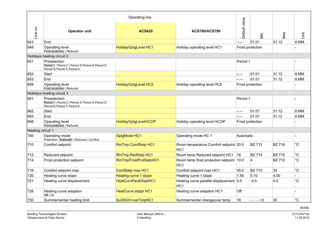
46/588
Building Technologies Division User Manual LMS14... CC1U7471en Infrastructure & Cities Sector 5 Handling 11.05.2012
Operating line
Line
no.
Operator unit ACS420 ACS700/ACS790
Def
ault
valu
e
Min
Max
Uni
t
643 End --.-- 01.01 31.12 tt.MM
648 Operating level Frost protection ¦ Reduced
HolidayOptgLevel HC1 Holiday operating level HC1 Frost protection -
Holidays heating circuit 2
651 Preselection Period 1 ¦ Period 2 ¦ Period 3¦ Period 4¦ Period 5¦ Period 6¦ Period 7¦ Period 8
Period 1 -
652 Start --.-- 01.01 31.12 tt.MM
653 End --.-- 01.01 31.12 tt.MM
658 Operating level Frost protection ¦ Reduced
HolidayOptgLevel HC2 Holiday operating level HC2 Frost protection -
Holidays heating circuit 3
661 Preselection Period 1 ¦ Period 2 ¦ Period 3¦ Period 4¦ Period 5¦ Period 6¦ Period 7¦ Period 8
Period 1 -
662 Start --.-- 01.01 31.12 tt.MM
663 End --.-- 01.01 31.12 tt.MM
668 Operating level Frost protection ¦ Reduced
HolidayOptgLevelHC3/P Holiday operating level HC3/P Frost protection -
Heating circuit 1
700 Operating mode Protection ¦ Automatic ¦ Reduced ¦ Comfort
OptgMode HC1 Operating mode HC 1 Automatic -
710 Comfort setpoint RmTmp ComfSetp HC1 Room temperature Comfort setpoint HC1
20.0 BZ 712 BZ 716 °C
712 Reduced setpoint RmTmp RedSetp HC1 Room temp Reduced setpoint HC1 16 BZ 714 BZ 710 °C
714 Frost protection setpoint RmTmpFrostProtSetpHC1 Room temp frost protection setpoint HC1
10.0 4 BZ 712 °C
716 Comfort setpoint max ComfSetp max HC1 Comfort setpoint max HC1 35.0 BZ 710 35 °C
720 Heating curve slope Heating curve 1 slope Heating curve 1 slope 1.50 0.10 4.00 -
721 Heating curve displacement HeatCurvParalDisplHC1 Heating curve parallel displacement HC1
0.0 -4,5 4,5 °C
726 Heating curve adaption Off ¦ On
HeatCurve adapt HC1 Heating curve adaption HC1 Off -
730 Summer/winter heating limit Su/WiCh’overTmpHC1 Summer/winter changeover temp 18 / 8 30 °C

47/588
Building Technologies Division User Manual LMS14... CC1U7471en Infrastructure & Cities Sector 5 Handling 11.05.2012
Operating line
Line
no.
Operator unit ACS420 ACS700/ACS790
Def
ault
valu
e
Min
Max
Uni
t
HC1
732 24-hour heating limit 24hourHeatLimit HC1 24-hour heating limit HC1 -3 / -10 10 °C
733 Ext’n 24-hour heating limit
No ¦ Yes
Ext 24hour HeatLimHC1 Ext 24-hour heating limit HC1 Yes
740 Flow temp setpoint min FlowTmp MinLimitn HC1 Flow temp min limitation HC1 8 8 BZ 741 °C
741 Flow temp setpoint max FlowTmp MaxLimitn HC1 Flow temp max limitation HC1 80 BZ 740 95 °C
742 Flow temp setpoint room stat FlowSetpRmStat HC1 Flow temp setpoint room thermostat HC1
65 /BZ 740 /BZ 741
°C
744 Swi-on ratio room stat SwiOnRat RmStat HC1 Swi-on ratio room thermostat HC1 /1 99 %
746 Delay heat request Delay request HC1 Delay heat request HC1 0 0 600 s
750 Room influence RmTmp gain factor HC1 Room temp gain factor HC1 /1 100 %
760 Room temp limitation RmTmp limitation HC 1 Room temperature limitation HC1 1 /0.5 4 °C
761 Heating limit room controller HeatLimit RmContr HC1 Heating limit room control HC1 /0 100 %
770 Boost heating RmTmp SetpBoost HC1 Room temp setpoint boost HC1 (boost heating)
5 /0 20 °C
780 Quick setback Off ¦ Down to reduced setpoint ¦ Down to frost prot setpoint
Quick setback HC1 Quick setback HC1 Down to reduced setpoint -
790 Optimum start control max OptStartCtrl MaxTime1 Optimum start control max forward shift HC1
0 0 360 Min.
791 Optimum top control max OptStopCtrl MaxTime1 Optimum stop control max forward shift HC1
0 0 360 Min.
794 Heat up gradient Heat up gradient Heat up gradient 60 0 600 min/k
800 Reduced setp increase start StartRedRTSetpIncrHC1 Start reduced room temp setpoint increase HC1
/BZ 801 10 °C
801 Reduced setp increase end EndRedRTSetpIncrHC1 End reduced room temp setpoint increase HC1
-15 -30 BZ 800 °C
809 Continuous pump operation
No ¦ Yes
Continuous PumpOp HC1 Continuous pump operation HC1 No
812 Frost protection flow temp Off ¦ On
FrostProtFlowTemp HC1 Frost protection flow temp HC1 On -
820 Overtemp prot pump circuit Off ¦ On
OvertempProt HC1 Pump heating circuit overtemp protection HC1
On -

48/588
Building Technologies Division User Manual LMS14... CC1U7471en Infrastructure & Cities Sector 5 Handling 11.05.2012
Operating line
Line
no.
Operator unit ACS420 ACS700/ACS790
Def
ault
valu
e
Min
Max
Uni
t
830 Mixing valve boost MixValveSetpBoost HC1 Mixing valve setpoint boost HC1 5 0 50 °C
832 Actuator type 2-positioin ¦ 3-position
Actuator CtrlMod HC1 Actuator control mode HC1 3-position -
833 Switching differential 2-pos ActuatorSwiDiff HC1 Actuator switching differential HC1 2 0 20 °C
834 Actuator running time Actuator RunTime HC1 Actuator running time HC1 120 30 873 s
835 Mixing valve Xp Xp heating circuit 1 P-band (Xp) HC1 32 1 100 °C
836 Mixing valve Tn Tn heating circuit 1 Integral action time (Tn) HC1 120 10 873 s
850 Floor curing function Off ¦ Functional heating ¦ Curing heating ¦ Functional/curing heating ¦ Curing/functional heating ¦ Manually
FloorDryUp funct 1 Floor dry up function HC1 Off -
851 Floor curing setp manually FloorSetp man HC1 Floor setpoint manually HC1 25 0 95 °C
855 Floor curing setp current FlowTempSetp floor1 Flow temp setpoint floor curing HC1 0 95 °C
856 Floor curing day current FloorDryUp day 1 Floor dry up day HC1 0 32
861 Excess heat draw Off ¦ Heating mode ¦ Always
Overtemp drop HC1 Overtemperature drop HC1 Always
870 With buffer No ¦ Yes
HC1 with buffer Heating circuit 1 with buffer Yes -
872 With prim contr/system pump No ¦ Yes
HC1 prectrl/SystPump Heating circuit 1 with precontrol/system pump
Yes
880 Pump speed reduction Operating level ¦ Characteristic
Pump speed red HC1 Pump speed reduction HC1 Characteristic
881 Starting speed Starting speed HC1 Starting speed HC1 100 0 100 %
882 Pump speed min Pump speed min HC1 Pump speed min HC1 50 BZ 885 BZ 883 %
883 Pump speed max Pump speed max HC1 Pump speed max HC1 100 BZ 882 BZ 886 %
885 Pump speed min OEM Pump speed minOEMHC1 Pump speed min OEM HC1 50 0 BZ 882 %
886 Pump speed max OEM Pump speed maxOEMHC1 Pump speed max OEM HC1 100 BZ 883 100 %
888 Curve readj at 50% speed CurveReadj50%SpeedHC1 Curve readj at 50% speed HC1 33 0 100 %
889 Filter time const speed ctrl FilterTmeSpeedCtrlHC1 Filter time const speed ctrl HC1 5 0 20 Min.
890 Flow setp readj speed ctrl No ¦ Yes
FlowReadjSpeedCtrlHC1 Flow setp readj speed ctrl HC1 Yes
898 Operating level changeover Frost protection ¦ Reduced ¦ Comfort
OptgLevelCh’over HC1 Operating level changeover HC1 Reduced
900 Optg mode changeover OptgModeCh’over HC1 Operating mode changeover HC1 Protection

49/588
Building Technologies Division User Manual LMS14... CC1U7471en Infrastructure & Cities Sector 5 Handling 11.05.2012
Operating line
Line
no.
Operator unit ACS420 ACS700/ACS790
Def
ault
valu
e
Min
Max
Uni
t
None ¦ Protection ¦ Reduced ¦ Comfort ¦ Automatic
[4291.1] Delay speed ctrl HC1 Delay speed control HC1 5 - - - / 0 60 Min.
Cooling circuit 1
901 Operating mode cooling circuit 1 Off ¦ Automatic
OptgMode CC1 Operating mode cooling circuit 1 Off -
904 Protection setpoint cooling circuit 1 RmTmp prot setp CC1 Room temp protection setpoint cooling circuit 1
40 - - - / 15 40 °C
932 Room temp limitation cooling circuit 1 RmTmp limitation CC1 Room temp limitation cooling circuit 1
1 - - - / 0,5 4 °C
Heating circuit 2
1000 Operating mode Protection ¦ Automatic ¦ Reduced ¦ Comfort
OptgMode HC2 Operating mode heat circuit 2 Automatic -
1010 Comfort setpoint RoomTemp ComfSetp HC2 Room temperature Comfort setpoint HC2
20.0 BZ 1012 BZ 1016 °C
1012 Reduced setpoint RmTmp RedSetp HC2 Room temp reduced setpoint heat circuit 2
16 BZ 1014 BZ 1010 °C
1014 Frost protection setpoint RmTmpFrostProtSetpHC2 Room temp frost protection setpoint HC2
10.0 4 BZ 1012 °C
1016 Comfort setpoint max ComfortSetp max HC2 Comfort setpoint max HC2 35.0 BZ 1010 35 °C
1020 Heating curve slope Heating curve 2 slope Heating curve 2 slope 1.50 0.10 4.00 -
1021 Heating curve displacement HeatCurvParalDisplHC2 Heating curve parallel displacement HC2
0.0 -4.5 4.5 °C
1026 Heating curve adaption Off ¦ On
HeatCurve adapt HC2 Heating curve adaptation heat circuit 2
Off -
1030 Summer/winter heating limit Su/WiCh’overTmpHC2 Summer/winter changeover temp heat circuit 2
18 /8 30 °C
1032 24-hour heating limit 24hour HeatLimit HC2 24-hour heating limit HC2 -3 /-10 10 °C
1033 Ext’n 24-hour heating limit
No ¦ Yes
Ext 24hour HeatLimHC2 Ext 24-hour heating limit HC2 Yes
1040 Flow temp setpoint min FlowTmp MinLimitn HC2 Flow temp min limitation heat circuit 2
8 8 BZ 1041 °C
1041 Flow temp setpoint max FlowTmp MaxLimitn HC2 Flow temp max limitation heat circuit 2
80 BZ 1040 95 °C

50/588
Building Technologies Division User Manual LMS14... CC1U7471en Infrastructure & Cities Sector 5 Handling 11.05.2012
Operating line
Line
no.
Operator unit ACS420 ACS700/ACS790
Def
ault
valu
e
Min
Max
Uni
t
1042 Flow temp setpoint room stat FlowSetp RmStat HC2 Flow temp setpoint room thermostat HC2
65 /BZ 1040
BZ 1041 °C
1044 Swi-on ratio room stat SwiOnRat RmStat HC2 Swi-on ratio room thermostat HC2 /1 99 %
1046 Delay heat request Delay request HC2 Delay heat request HC2 0 0 600 s
1050 Room influence RmTmp gain factor HC2 Room temp gain factor HC2 20 /1 100 %
1060 Room temp limitation RmTmp limitation HC 2 Room temperature limitation HC2 1 /0.5 4 °C
1061 Heating limit room controller Heating limit RC HC2 Heating limit room control HC2 /0 100 %
1070 Boost heating RmTmp SetpBoost HC2 Room temp setpoint boost HC2 (boost heating)
5 /0 20 °C
1080 Quick setback Off ¦ Down to reduced setpoint ¦ Down to frost prot setpoint
Quick setback HC2 Quick setback HC2 Down to reduced setpoint -
1090 Optimum start control max OptStartCtrl MaxTime2 Optimum start control max forward shift HC2
0 0 360 Min.
1091 Optimum top control max OptStopCtrl MaxTime2 Optimum stop control max forward shift HC2
0 0 360 Min.
1094 Heat up gradient Heat up gradient Heat up gradient 60 0 600 min/k
1100 Reduced setp increase start StartRedRTSetpIncrHC2 Start reduced room temp setpoint increase HC2
/BZ 1101
10 °C
1101 Reduced setp increase end EndRedRTSetpIncrHC2 End reduced room temp setpoint increase HC2
-15 -30 BZ 1100 °C
1109 Continuous pump operation
No ¦ Yes
Continuous PumpOp HC2 Continuous pump operation HC2 No
1112 Frost protection flow temp Off ¦ On
FrostProtFlowTemp HC2 Frost protection flow temp HC2 On
1120 Opertemp prot pump circuit Off ¦ On
HC2 overtemp prot Pump heating circuit overtemp protection HC2
On -
1130 Mixing valve boost MixValveSetpBoost HC2 Mixing valve setpoint boost HC2 5 0 50 °C
1132 Actuator type 2-position ¦ 3-position
Actuator CtrlMode HC2 Actuator control mode HC2 3-position -
1133 Switching differential 2-pos Actuator SwiDiff HC2 Actuator switching differential HC2 2 0 20 °C
1134 Actuator running time Actuator RunTime HC2 Actuator running time HC2 120 30 873 s
1135 Mixing valve Xp Xp heating circuit 2 P-band (Xp) HC2 32 1 100 °C
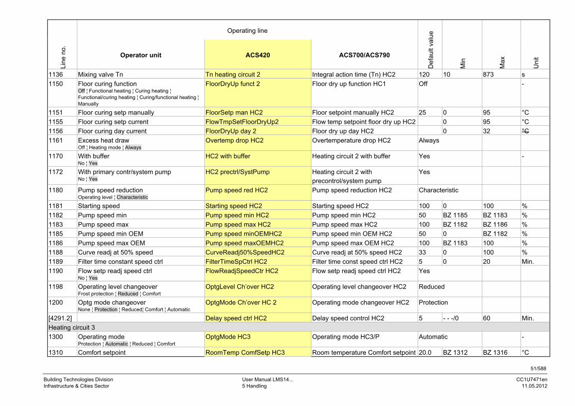
51/588
Building Technologies Division User Manual LMS14... CC1U7471en Infrastructure & Cities Sector 5 Handling 11.05.2012
Operating line
Line
no.
Operator unit ACS420 ACS700/ACS790
Def
ault
valu
e
Min
Max
Uni
t
1136 Mixing valve Tn Tn heating circuit 2 Integral action time (Tn) HC2 120 10 873 s
1150 Floor curing function Off ¦ Functional heating ¦ Curing heating ¦ Functional/curing heating ¦ Curing/functional heating ¦ Manually
FloorDryUp funct 2 Floor dry up function HC1 Off -
1151 Floor curing setp manually FloorSetp man HC2 Floor setpoint manually HC2 25 0 95 °C
1155 Floor curing setp current FlowTmpSetFloorDryUp2 Flow temp setpoint floor dry up HC2 0 95 °C
1156 Floor curing day current FloorDryUp day 2 Floor dry up day HC2 0 32 °C
1161 Excess heat draw Off ¦ Heating mode ¦ Always
Overtemp drop HC2 Overtemperature drop HC2 Always
1170 With buffer No ¦ Yes
HC2 with buffer Heating circuit 2 with buffer Yes -
1172 With primary contr/system pump No ¦ Yes
HC2 prectrl/SystPump Heating circuit 2 with precontrol/system pump
Yes
1180 Pump speed reduction Operating level ¦ Characteristic
Pump speed red HC2 Pump speed reduction HC2 Characteristic
1181 Starting speed Starting speed HC2 Starting speed HC2 100 0 100 %
1182 Pump speed min Pump speed min HC2 Pump speed min HC2 50 BZ 1185 BZ 1183 %
1183 Pump speed max Pump speed max HC2 Pump speed max HC2 100 BZ 1182 BZ 1186 %
1185 Pump speed min OEM Pump speed minOEMHC2 Pump speed min OEM HC2 50 0 BZ 1182 %
1186 Pump speed max OEM Pump speed maxOEMHC2 Pump speed max OEM HC2 100 BZ 1183 100 %
1188 Curve readj at 50% speed CurveReadj50%SpeedHC2 Curve readj at 50% speed HC2 33 0 100 %
1189 Filter time constant speed ctrl FilterTimeSpCtrl HC2 Filter time const speed ctrl HC2 5 0 20 Min.
1190 Flow setp readj speed ctrl No ¦ Yes
FlowReadjSpeedCtr HC2 Flow setp readj speed ctrl HC2 Yes
1198 Operating level changeover Frost protection ¦ Reduced ¦ Comfort
OptgLevel Ch’over HC2 Operating level changeover HC2 Reduced
1200 Optg mode changeover None ¦ Protection ¦ Reduced¦ Comfort ¦ Automatic
OptgMode Ch’over HC 2 Operating mode changeover HC2 Protection
[4291.2] Delay speed ctrl HC2 Delay speed control HC2 5 - - -/0 60 Min.
Heating circuit 3
1300 Operating mode Protection ¦ Automatic ¦ Reduced ¦ Comfort
OptgMode HC3 Operating mode HC3/P Automatic -
1310 Comfort setpoint RoomTemp ComfSetp HC3 Room temperature Comfort setpoint 20.0 BZ 1312 BZ 1316 °C
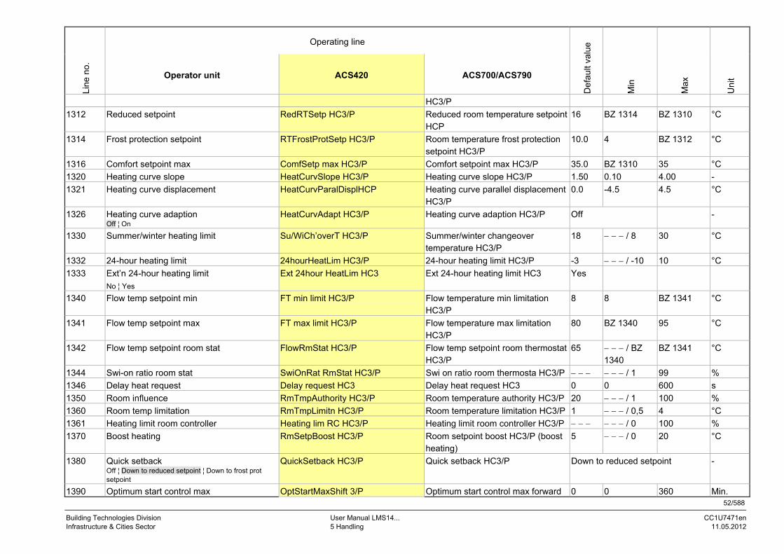
52/588
Building Technologies Division User Manual LMS14... CC1U7471en Infrastructure & Cities Sector 5 Handling 11.05.2012
Operating line
Line
no.
Operator unit ACS420 ACS700/ACS790
Def
ault
valu
e
Min
Max
Uni
t
HC3/P
1312 Reduced setpoint RedRTSetp HC3/P Reduced room temperature setpoint HCP
16 BZ 1314 BZ 1310 °C
1314 Frost protection setpoint RTFrostProtSetp HC3/P Room temperature frost protection setpoint HC3/P
10.0 4 BZ 1312 °C
1316 Comfort setpoint max ComfSetp max HC3/P Comfort setpoint max HC3/P 35.0 BZ 1310 35 °C
1320 Heating curve slope HeatCurvSlope HC3/P Heating curve slope HC3/P 1.50 0.10 4.00 -
1321 Heating curve displacement HeatCurvParalDisplHCP Heating curve parallel displacement HC3/P
0.0 -4.5 4.5 °C
1326 Heating curve adaption Off ¦ On
HeatCurvAdapt HC3/P Heating curve adaption HC3/P Off -
1330 Summer/winter heating limit Su/WiCh’overT HC3/P Summer/winter changeover temperature HC3/P
18 / 8 30 °C
1332 24-hour heating limit 24hourHeatLim HC3/P 24-hour heating limit HC3/P -3 / -10 10 °C
1333 Ext’n 24-hour heating limit
No ¦ Yes
Ext 24hour HeatLim HC3 Ext 24-hour heating limit HC3 Yes
1340 Flow temp setpoint min FT min limit HC3/P Flow temperature min limitation HC3/P
8 8 BZ 1341 °C
1341 Flow temp setpoint max FT max limit HC3/P Flow temperature max limitation HC3/P
80 BZ 1340 95 °C
1342 Flow temp setpoint room stat FlowRmStat HC3/P Flow temp setpoint room thermostat HC3/P
65 / BZ 1340
BZ 1341 °C
1344 Swi-on ratio room stat SwiOnRat RmStat HC3/P Swi on ratio room thermosta HC3/P / 1 99 %
1346 Delay heat request Delay request HC3 Delay heat request HC3 0 0 600 s
1350 Room influence RmTmpAuthority HC3/P Room temperature authority HC3/P 20 / 1 100 %
1360 Room temp limitation RmTmpLimitn HC3/P Room temperature limitation HC3/P 1 / 0,5 4 °C
1361 Heating limit room controller Heating lim RC HC3/P Heating limit room controller HC3/P / 0 100 %
1370 Boost heating RmSetpBoost HC3/P Room setpoint boost HC3/P (boost heating)
5 / 0 20 °C
1380 Quick setback Off ¦ Down to reduced setpoint ¦ Down to frost prot setpoint
QuickSetback HC3/P Quick setback HC3/P Down to reduced setpoint -
1390 Optimum start control max OptStartMaxShift 3/P Optimum start control max forward 0 0 360 Min.

53/588
Building Technologies Division User Manual LMS14... CC1U7471en Infrastructure & Cities Sector 5 Handling 11.05.2012
Operating line
Line
no.
Operator unit ACS420 ACS700/ACS790
Def
ault
valu
e
Min
Max
Uni
t
shift HC3/P
1391 Optimum top control max OptStopMaxShift 3/P Optimum stop control max forward shift HC3/P
0 0 360 Min.
1394 Heat up gradient Heat up gradient Heat up gradient 60 0 600 min/K
1400 Reduced setp increase start StartRedRTIncr HC3/P Start reduced room temp setpoint increase HC3/P
/ BZ 1401
10 °C
1401 Reduced setp increase end EndRedRTIncr HC3/P End reduced room temp setpoint increase HC3/P
-15 -30 BZ 1400 °C
1409 Continuous pump operation
No ¦ Yes
Continuous PumpOp HC3 Continuous pump operation HC3 No
1412 Frost protection flow temp Off ¦ On
FrostProtFlowTemp HC3 Frost protection flow temp HC3 On
1420 Overtemp prot pump circuit Off ¦ On
OvertempProt HC3/P Pump heating circuit overtemp protection HC3/P
On -
1430 Mixing valve boost MixValveBoost HC3/P Mixing valve setpoint boost HC3/P 5 0 50 °C
1432 Actuator type 2-position ¦ 3-position
ActuatorCtrlMod HC3/P Actuator control mode HC3/P 3-position -
1433 Switching differential 2-pos ActuatorSwiDiff HC3/P Actuator switching differential heat circuit 3/P
2 0 20 °C
1434 Actuator running time ActuatorRunTime HC3/P Actuator running time heat circuit 3/P
120 30 873 s
1435 Mixing valve Xp Xp heating circuit 3/P P-band (Xp) HC3/P 32 1 100 °C
1436 Mixing valve Tn Tn heating circuit 3/P Integral action time (Tn) HC3/P 120 10 873 s
1450 Floor curing function Off ¦ Functional heating ¦ Curing heating ¦ Functional/curing heating ¦ Curing/functional heating ¦ Manually
FloorCur funct HC3/P Floor curing function HC3/P Off -
1451 Floor curing setp manually FloorSetp man HC3/P Floor setpoint manually HC3/P 25 0 95 °C
1455 Floor curing setp current FTSetpFloorCur HC3/P Flow temperature setpoint floor curing HC3/P
0 95 °C
1456 Floor curing day current FloorCuringDay HC3/P Floor curing day HC3/P 0 32
1461 Excess heat draw Off ¦ Heating mode ¦ Always
Overtemp drop HC3/P Overtemperature drop HC3/P Always
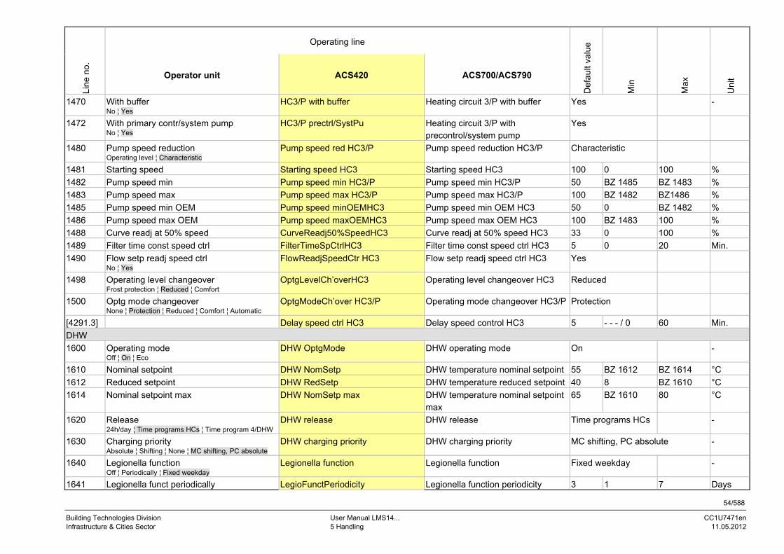
54/588
Building Technologies Division User Manual LMS14... CC1U7471en Infrastructure & Cities Sector 5 Handling 11.05.2012
Operating line
Line
no.
Operator unit ACS420 ACS700/ACS790
Def
ault
valu
e
Min
Max
Uni
t
1470 With buffer No ¦ Yes
HC3/P with buffer Heating circuit 3/P with buffer Yes -
1472 With primary contr/system pump No ¦ Yes
HC3/P prectrl/SystPu Heating circuit 3/P with precontrol/system pump
Yes
1480 Pump speed reduction Operating level ¦ Characteristic
Pump speed red HC3/P Pump speed reduction HC3/P Characteristic
1481 Starting speed Starting speed HC3 Starting speed HC3 100 0 100 %
1482 Pump speed min Pump speed min HC3/P Pump speed min HC3/P 50 BZ 1485 BZ 1483 %
1483 Pump speed max Pump speed max HC3/P Pump speed max HC3/P 100 BZ 1482 BZ1486 %
1485 Pump speed min OEM Pump speed minOEMHC3 Pump speed min OEM HC3 50 0 BZ 1482 %
1486 Pump speed max OEM Pump speed maxOEMHC3 Pump speed max OEM HC3 100 BZ 1483 100 %
1488 Curve readj at 50% speed CurveReadj50%SpeedHC3 Curve readj at 50% speed HC3 33 0 100 %
1489 Filter time const speed ctrl FilterTimeSpCtrlHC3 Filter time const speed ctrl HC3 5 0 20 Min.
1490 Flow setp readj speed ctrl No ¦ Yes
FlowReadjSpeedCtr HC3 Flow setp readj speed ctrl HC3 Yes
1498 Operating level changeover Frost protection ¦ Reduced ¦ Comfort
OptgLevelCh’overHC3 Operating level changeover HC3 Reduced
1500 Optg mode changeover None ¦ Protection ¦ Reduced ¦ Comfort ¦ Automatic
OptgModeCh’over HC3/P Operating mode changeover HC3/P Protection
[4291.3] Delay speed ctrl HC3 Delay speed control HC3 5 - - - / 0 60 Min.
DHW
1600 Operating mode Off ¦ On ¦ Eco
DHW OptgMode DHW operating mode On -
1610 Nominal setpoint DHW NomSetp DHW temperature nominal setpoint 55 BZ 1612 BZ 1614 °C
1612 Reduced setpoint DHW RedSetp DHW temperature reduced setpoint 40 8 BZ 1610 °C
1614 Nominal setpoint max DHW NomSetp max DHW temperature nominal setpoint max
65 BZ 1610 80 °C
1620 Release 24h/day ¦ Time programs HCs ¦ Time program 4/DHW
DHW release DHW release Time programs HCs -
1630 Charging priority Absolute ¦ Shifting ¦ None ¦ MC shifting, PC absolute
DHW charging priority DHW charging priority MC shifting, PC absolute -
1640 Legionella function Off ¦ Periodically ¦ Fixed weekday
Legionella function Legionella function Fixed weekday -
1641 Legionella funct periodically LegioFunctPeriodicity Legionella function periodicity 3 1 7 Days

55/588
Building Technologies Division User Manual LMS14... CC1U7471en Infrastructure & Cities Sector 5 Handling 11.05.2012
Operating line
Line
no.
Operator unit ACS420 ACS700/ACS790
Def
ault
valu
e
Min
Max
Uni
t
1642 Legionella funct weekday Monday ¦ Tuesday ¦ Wednesday ¦ Thursday ¦ Friday ¦ Saturday ¦ Sunday
LegioFunction Day Legionella function day Monday
1644 Legionella function time LegioFunctTime Time for legionella function / 00:00 23:50 hh:mm
1645 Legionella funct setpoint LegionellaFunctSetp Legionella function setpoint 65 55 95 °C
1646 Legionella funct duration DwellTimeLegFunctSetp Dwelling time at legionella function setpoint
30 / 10 360 Min.
1647 Legionella funct circ pump Off ¦ On
CircPumpOpLegioFunct Circulating pump operation during legionella function
On -
1660 Circulating pump release Time program 3/HC3 ¦ DHW release ¦ Time program 4/DHW ¦ Time program 5
DHW CircPump release DHW circulation pump release DHW release -
1661 Circulating pump cycling Off ¦ On
DHW CircPump cycling DHW circulating pump cycling On -
1663 Circulation setpoint DHW Circ Setpoint DHW circulation setpoint 45 8 80 °C
1680 Optg mode changeover
None ¦ Off ¦ On ¦ Eco
OptgModeCh’over DHW Operating mode changeover DHW Off
Consumer circuit 1
1859 Flow temp setp cons request FlowTSetpConsReq 1 Flow temp setp cons request 1 70 8 120 °C
1874 DHW charging priority No ¦ Yes
DHWChargPrio ConsC1 DHW charging priority consumer circuit 1
Yes
1875 Excess heat draw Off ¦ On
Overtemp drop ConsC1 Overtemperature drop consumer circuit 1
On
1878 With buffer No ¦ Yes
ConsC1 with buffer Consumer circuit 1 with buffer Yes
1880 With prim contr/system pump No ¦ Yes
ConsC1 prectrl/SystPu Consumer circuit 1 with precontrol/system pump
Yes
Consumer circuit 2
1909 Flow temp setp cons request FlowTSetpConsReq 2 Flow temp setp cons request 2 70 8 120 °C
1924 DHW charging priority No ¦ Yes
DHWChargPrio ConsC2 DHW charging priority consumer circuit 2
Yes
1925 Excess heat draw Off ¦ On
Overtemp drop ConsC2 Overtemperature drop consumer circuit 2
On

56/588
Building Technologies Division User Manual LMS14... CC1U7471en Infrastructure & Cities Sector 5 Handling 11.05.2012
Operating line
Line
no.
Operator unit ACS420 ACS700/ACS790
Def
ault
valu
e
Min
Max
Uni
t
1928 With buffer No ¦ Yes
ConsC2 with buffer Consumer circuit 2 with buffer Yes
1930 With prim contr/system pump No ¦ Yes
ConsC2PreCtrl/SystPu Consumer circuit 2 with precontrol/system pump
Yes
Swimming pool circuit
1959 Flow temp setp swi pool FlowTmpSetp SwiPool Flow temp setp swimming pool 70 8 120 °C
1974 DHW charging priority No ¦ Yes
DHWChargPrio SwiPool DHW charging priority swimming pool circuit
Yes
1975 Excess heat draw Off ¦ On
Overtemp drop SwiPool Overtemperature drop swimming pool circuit
On
1978 With buffer No ¦ Yes
SwiPool with buffer Swimming pool circuit with buffer Yes
1980 With prim contr/system pump No ¦ Yes
SwiPoolPrectrl/SystPu Swimming pool circuit with precontrol/system pump
Yes
Swimming pool
2055 Setpoint solar heating SwiPool setpoint solar Swimming pool setpoint solar heating
26 8 80 °C
2056 Setpoint source heating SwiPool setp source Swimming pool setpoint heat source 22 8 80 °C
2065 Charging priority solar Priority 1 ¦ Priority 2 ¦ Priority 3
SwiPool temp max Swimming pool temperature maximum
Priority 3
2070 Swimming pool temp max SwiPool with solar Swimming pool with solar 32 BZ 2055 95 °C
2080 With solar integration No ¦ Yes
SwiPool setpoint solar Swimming pool setpoint solar heating
Yes
Primary contr/system pump
2110 Flow temp setpoint min FT MinLimitn prectrl Flow temp min limitation precontrol 8 8 BZ 2111 °C
2111 Flow temp setpoint max FT MaxLimitn prectrl Flow temp max limitation prectrl 80 BZ 2110 95 °C
2121 System pump on heat gen lock
Off ¦ On
SystPump HeatGenLock System pump on heat gen lock Off
2130 Mixing valve boost MixVaSetpBstPrimContr Mixing valve setpoint boost primary controller
10 0 50 °C
2132 Actuator type 2-position ¦ 3-position
ActCtrlMode prectrl Actuator control mode prectrl 3-position
2133 Switching differential 2-pos ActSwiDiff prectrl Actuator switching differential prectrl 2 0 20 °C

57/588
Building Technologies Division User Manual LMS14... CC1U7471en Infrastructure & Cities Sector 5 Handling 11.05.2012
Operating line
Line
no.
Operator unit ACS420 ACS700/ACS790
Def
ault
valu
e
Min
Max
Uni
t
2134 Actuator running time ActRunTime prectrl Actuator running time prectrl 120 30 873 s
2135 Mixing valve Xp Xp primary controller P-band (Xp) primary controller 32 1 100 °C
2136 Mixing valve Tn Tn primary controller Integral action time (Tn) primary controller
120 10 873 s
2150 Primary contr/system pump Before buffer ¦ After buffer
PrimContr/SystPump Primary controller/system pump After buffer -
Boiler
2203 Release below outside temp Release below OT Release below outside temp 0 - - - / -50 50 °C
2208 Full charging buffer
Off ¦ On
Full charging buffer Full charging buffer Off
2210 Setpoint min BoilTmp MinLimitn Boiler temp min limitation 40 BZ 2211 BZ2214 °C
2211 Setpoint min OEM BoilTmp MinLimitn OEM Boiler temp min limitation OEM 40 8 BZ 2210 °C
2212 Setpoint max BoilTmp MaxLimitn Boiler temp max limitation 80 BZ 2214 BZ 2213 °C
2213 Setpoint max OEM BoilTmp MaxLimitn OEM Boiler temp max limitation OEM 85 BZ 2212 120 °C
2214 Setpoint manual control BoilerSetp man Boiler temperature setpoint in manual operation
60 BZ 2210 BZ 2212 °C
2217 Setpoint frost protection Setp frost protection Setpoint frost protection 8 - - - / -20 20 °C
2233 P-band Xp HCs P-band Xp HCs P-band Xp HCs 52 1 200 °C
2234 Int action time Tn HCs Tn heating Integral action time (Tn) heating 80 4 873 s
2235 Der action time Tv HCs Tv heating Derivative action time (Tv) heating 0 0 30 s
2236 P-band Xp DHW P-band Xp DHW P-band Xp DHW 34 1 200 °C
2237 Int action time Tn DHW Tn DHW Integral action time (Tn) DHW 80 4 873 s
2238 Der action time Tv DHW Tv DHW Derivative action time (Tv) DHW 8 0 30 s
2241 Burner running time min BurnRunTime MinLimtn Burner running time min limitation 0 0 20 Min.
2243 Burner off time min Burner off time min Burner off time min 0 0 20 Min.
2245 SD burner off time SD burner off time Max control diff without aborting pause
15 0 80 °C
2250 Pump overrun time Pump overrun time Pump overrun time 5 0 240 Min.
2253 Pump overr time after DHW PumpOverrun after DHW Pump overrun time after DHW 1 0 20 Min.
2260 Prot boil startup consumers ProtStartupConsumers Protective startup consumers Off
2263 Setpoint min on shutdown SetpMin on shutdown Setpoint min on shutdown Off
2264 Prot boil startup anticipation ForeseeTmeStartupProt Foreseeable time during protective 0 0 240 s

58/588
Building Technologies Division User Manual LMS14... CC1U7471en Infrastructure & Cities Sector 5 Handling 11.05.2012
Operating line
Line
no.
Operator unit ACS420 ACS700/ACS790
Def
ault
valu
e
Min
Max
Uni
t
startup
2270 Return setpoint min RetTmp limitation Return temp limitation 8 BZ 2271 95 °C
2271 Return setpoint min OEM MinLimtnBoilRetTmpEXP Min limitation of the boiler return temp EXP
8 8 BZ 2270 °C
2272 Return influence consumers Off ¦ On
Boiler return Boiler return On
2300 Frost prot plant boiler pump Off ¦ On
FrostProt Plant BoilPump Frost protection for plant boiler pump
Off
2301 Boiler pump on heat gen lock
Off ¦ On
BoilPump HeatGenLock Boiler pump at heat gen lock Off
2305 Impact heat generation lock
Heating mode only ¦ Heating and DHW mode
Impact HeatGenLock Impact heat generation lock Heating mode only
2310 Limit thermostat function Off ¦ On
Limit stat function Limit stat function On
2316 Temp differential max TempDifferential max Temp differential max 20 / 0 80 °C
2317 Temp differential nominal TempDifferential nom Temp differential nominal 10 / 0 80 °C
2320 Pump modulation None ¦ Demand ¦ Boiler setpoint ¦ Temp differential nominal ¦ Burner output
Pump modulation Pump modulation Demand
2321 Starting speed Starting speed Starting speed 100 / 0 100 %
2322 Pump speed min Pump speed min boiler Pump speed min boiler 40 BZ 2327 BZ 2323 %
2323 Pump speed max Pump speed max boiler Pump speed max boiler 100 BZ 2322 BZ 2328 %
2324 Speed Xp Pump speed XP boiler Pump speed P-band XP boiler 32 1 200 °C
2325 Speed Tn Pump speed Tn boiler Pump speed integral action time (Tn) boiler
120 10 873 s
2326 Speed Tv Pump speed Tv boiler Pump speed derivative action time (Tv) boiler
10 0 30 s
2327 Pump speed min OEM PumpSpeedMinOEMBoiler Pump speed min OEM boiler 40 0 BZ 2322 %
2328 Pump speed max OEM Pump speed max OEM Pump speed max OEM 100 BZ 2323 100 %
2329 Pump setpoint reduction Pump setp reduction Pump setpoint reduction 10 0 20 °C
[6066.1] LimMinBoilPumpMod
Off | On
Limitation of minimum boiler pump modulation
Off
2330 Output nominal Nominal boiler output Nominal boiler output 50 0 2000 kW

59/588
Building Technologies Division User Manual LMS14... CC1U7471en Infrastructure & Cities Sector 5 Handling 11.05.2012
Operating line
Line
no.
Operator unit ACS420 ACS700/ACS790
Def
ault
valu
e
Min
Max
Uni
t
2331 Output basic stage Nominal output 1st st Nominal output 1st stage 30 0 2000 kW
2334 Output at pump speed min Outp at pump speed min Output at pump speed min 0 0 100 %
2335 Output at pump speed max Outp at pump speed max Output at pump speed max 100 0 100 %
2441 Fan speed heating max FanSpeed heating max Max speed at maximum output in heating mode
3800 BZ 9525 BZ 9530 Min.-1
2442 Fan speed full charging max FanSp full charg max Fan speed full charging max 3800 BZ 9525 BZ 9530 Min.-1
2443 Fan sp start value inst WH FanSpStrtValInstWH Fan speed start value inst WH 0 0 BZ 9530 Min.-1
2444 Fan speed DHW max Fan speed DHW max Fan speed DHW max - - - - - - / BZ 9525
BZ 9530 Min.-1
2445 Fan shutdown heating mode Off ¦ On
FanShDownHeatMode Fan shutdown heating mode Off
2446 Fan shutdown delay Fan shutdown delay Fan shutdown delay 3 0 200 s
2450 Controller delay Off ¦ Heating mode only ¦ DHW mode only ¦ Heating and DHW mode
Fan switch-off delay Fan switch-off delay Heating mode only
2452 Controller delay speed Controller delay speed Controller delay speed 2400 BZ 9525 BZ 9530 Min.-1
2453 Controller delay duration Controller delay Controller delay after burner is started up
10 0 255 s
2454 Switching diff on HCs SwiDiff on HCs Switching diff on HCs 4 0 20 °C
2455 Switching diff off min HCs SwiDiffOffMin HCs Switching diff off min HCs 5 0 20 °C
2456 Switching diff off max HCs SwiDiffOffMax HCs Switching diff off max HCs 7 0 20 °C
2457 Settling time HCs Settling time HCs Settling time HCs 10 0 240 Min.
2460 Switching diff on DHW SwiDiffOn DHW Switching diff on DHW 5 0 20 °C
2461 Switching diff off min DHW SwiDiffOffMin DHW Switching diff off min DHW 6 0 20 °C
2462 Switching diff off max DHW SwiDiffOffMax DHW Switching diff off max DHW 8 0 20 °C
2463 Settling time DHW Settling time DHW Settling time DHW 10 0 240 Min.
2464 Dyn SD on setpoint change Off ¦ On
DynSDOnSetpChange Dyn SD on setpoint change Off
2465 Min setpoint change dyn SD MinSetpChange dyn SD Min setpoint change dyn SD 20 0 80 °C
2466 Dyn SD with HC/DHW change Off ¦ On
Dyn SD HC/DHW change Dyn SD with HC/DHW change Off
2467 Dyn SD when burner on Off ¦ On
Dyn SD burner on Dyn SD when burner on On

60/588
Building Technologies Division User Manual LMS14... CC1U7471en Infrastructure & Cities Sector 5 Handling 11.05.2012
Operating line
Line
no.
Operator unit ACS420 ACS700/ACS790
Def
ault
valu
e
Min
Max
Uni
t
2470 Delay heat req special op Delay req special Delay heat req special op 0 0 600 s
2473 Flue gas temp output red FlueGasT OutpRed Treshold for output reduction at high flue gas temp
80 0 200 °C
2474 Flue gas temp swi-off limit FlueGasTmp off limit Flue gas temp switch-off limit 85 0 200 °C
2476 Flue gas superv shutdown Start prevention ¦ Lockout position
FlueGasSupervShDown Flue gas superv shutdown Lockout position
2477 Flue gas superv st prev tme FlueGasSupervStPrevT Flue gas superv start prev tme 10 10 218 Min.
2478 Flue gas temp output limit Flue gas OutputLimit Flue gas temp output limit 80 0 200 °C
2479 Fl’g superv time con rel mod Fl‘gTimeConRelMod Fl’g superv time con rel mod 0 0 50 s
2480 Static press superv sh'down Start prevention ¦ Lockout position
StatPrSupervShDown Static press superv shutdown Lockout position
2490 Dyn press superv sh'down Start prevention ¦ Lockout position
DynPressSupervShDown Dyn press superv shutdown Lockout position
2491 Dyn superv press diff min DynSupervPressDiffMin Dyn superv press diff min 0 0 5 bar
2492 Dyn superv press diff max DynSupervPressDiffMax Dyn superv press diff max 5 0 5 bar
2494 Dyn superv press increase No ¦ Yes
DynSupervPressInc Dyn superv press increase Ja
2495 Dyn press superv time Dyn PressSupervTime Dyn press superv time 0,2 0 10 s
2496 Dyn press superv time const Dyn PressSupervTConst Dyn press superv tme const 1,6 0,6 5 s
2500 Pressure switch shutdown Start prevention ¦ Lockout position
PressSwitchShutdown Pressure switch shutdown Lockout position
2502 Flow switch shutdown Start prevention ¦ Lockout position
FlowSwitchShutdown Flow switch shutdown Lockout position
2504 Min on time switch Min on time switch Min on time switch 0,2 0 25 s
2510 Quick shutdown temp grad QuickShDownTempGrad Quick shutdown temp grad / 0 10 °C
2511 Quick shutdown superv time QuickShDownSupervTime Quick shutdown superv time 10 1 20 s
2512 Quick shutdown superv RT Off ¦ On
QuickShDownSupervRT Quick shutdown superv RT Off
2527 Boiler temp output reduction Boil temp output red Boiler temp output reduction 80 0 140 °C
2528 Swi diff output reduction SwiDiff output red Swi diff output reduction 5 0 20 °C
2531 Cutout temp LT Cutout temp limit stat Cutout temperature limit thermostat 90 0 100 °C
[3911.1] D’t care trans TGrad Duration of don’t care transition temperature gradient
0 0 51 s
[3912.1] D’t care tr Ret ab Fl Duration of don’t care transition 0 0 51 s

61/588
Building Technologies Division User Manual LMS14... CC1U7471en Infrastructure & Cities Sector 5 Handling 11.05.2012
Operating line
Line
no.
Operator unit ACS420 ACS700/ACS790
Def
ault
valu
e
Min
Max
Uni
t
return above flow
[4091.1] Max rate FT increase Maximum rate of flow temperature increase
3 0 20 K
[3913.1] NumErr TmpGrad in 24h Number of errors of temperature gradient in 24 hours
20 0 50
[3914.1] NumErr SLT in 24h Number of errors SLT cutout in 24 hours
20 0 50
[3916.1] Max delta flow-return Max delta between flow and return 40 0 50 °C
[3921.1] NumErr d-T in 24h Number of errors delta T in 24 hours 20 0 50
[3923.1] SwiDiff Ret ab Flow Switching differential return above flow
15 5 20 °C
[3924.1] NumErr Ret ab Fl 24h Number of errors return above flow in 24 hours
20 0 50
[3639.1] TempBoilMaxSLTSec TempBoilerMaxSLTSec 95 0 110 °C
[3925.1] TempReturnMaxSLTSec TempReturnMaxSLTSec 95 0 110 °C
2630 Auto deaeration procedure Off ¦ On
Auto deaeration proc Auto deaeration procedure Off
2655 ON time deaeration ON time deaeration ON time deaeration 10 0 240 s
2656 OFF time deaeration OFF time deaeration OFF time deaeration 5 0 240 s
2657 Number of repetitions Number of repetitions Number of repetitions 3 0 100 s
2662 Deaeration time heat circuit Deaeration time HC Deaeration time heating circuit 10 0 255 Min.
2663 Deaeration time DHW Deaeration time DHW Deaeration time DHW 5 0 255 Min.
[4195.1] Dyn press supervision Dynamic press supervision None
[4196.1] Flow supervision Flow supervision None
[4197.1] Outp red press switch Output reduction with pressure switch
On
[4198.1] Dyn PressSupPumpDelay Dynamic pressure supervision pump delay
0 0 10 s
[4199.1] Dyn PressSupRepet Dynamic pressure supervision repetitions
6 0 10
[4200.1] Dyn PressSup Pause Dynamic pressure supervision pause
600 0 1200 s

62/588
Building Technologies Division User Manual LMS14... CC1U7471en Infrastructure & Cities Sector 5 Handling 11.05.2012
Operating line
Line
no.
Operator unit ACS420 ACS700/ACS790
Def
ault
valu
e
Min
Max
Uni
t
[4201.1] Dyn PressSup WarnOffs Dynamic pressure supervision warning offset
0,2 0 1 bar
[4202.1] Dyn PressSup AutoAct Dynamic pressure supervision AutoActive
On
Cascade
3510 Lead strategy Late on, early off ¦ Late on, late off ¦ Early on, late off
CascadeControlStrat Cascade control strategy Late on, early off
3511 Output band min Output range Pmin Output range, lower limit (Pmin) 40 0 BZ 3512 %
3512 Output band max Output range Pmax Output range, upper limit (Pmax) 90 BZ 3511 100 %
3530 Release integral source seq RelLimit SourceSeq Release limit source sequence 50 0 500 °C*Min.
3531 Reset integral source seq ResetLimit SourceSeq Reset limit source sequence 20 0 500 °C*Min.
3532 Restart lock Restart lock time Restart lock time 300 0 1800 s
3533 Switch on delay SwitchOnDelayLagSourc Switch-on delay lag heat source 5 0 120 Min.
3534 Forced time basic stage ForcedTimeBasicStage Forced time basic stage when source is switched on
60 0 1200 s
3540 Auto source seq ch'over Time SourceSeqSwitch Time to automatic source sequence switching
500 / 10 990 h
3541 Auto source seq exclusion None ¦ First ¦ Last ¦ First and last
Excl SourceSeqSwitch Exclusion automatic source sequence switching
None
3544 Leading source Source 1 ¦ Source 2 ¦ Source 3 ¦ Source 4 ¦ Source 5 ¦ Source 6 ¦ Source 7 ¦ Source 8 ¦ Source 9 ¦ Source 10 ¦ Source 11 ¦ Source 12 ¦ Source 13 ¦ Source 14 ¦ Source 15 ¦ Source 16
Leading source Leading source Source 1
3560 Return setpoint min Cascade RetSetpMin Cascade return setpoint minimum 8 BZ 3561 95 °C
3561 Return setpoint min OEM Cascade RetSetpMinOEM Cascade return setpoint minimum OEM
8 8 BZ 3560 °C
3562 Return influence consumers Off ¦ On
Boiler return Cascade return On
3590 Temp differential min MinTmpDiff HydrBalanc Min temp differential hydraulic balancing
- - - / 0 20 °C
Extra heat source
3690 Setpoint incr main source SetpIncrMainSource Setpoint incr main source 5 0 10 °C

63/588
Building Technologies Division User Manual LMS14... CC1U7471en Infrastructure & Cities Sector 5 Handling 11.05.2012
Operating line
Line
no.
Operator unit ACS420 ACS700/ACS790
Def
ault
valu
e
Min
Max
Uni
t
Solar
3810 Temp diff on TempDiff solar on Temp differential solar on 8 BZ 3811 40 °C
3811 Temp diff off TempDiff solar off Temp differential solar off 4 0 BZ 3810 °C
3812 Charg temp min DHW st tank MinChargTemp DHW Min charging temperature DHW storage tank
/ 8 95 °C
3813 Temp diff on buffer TempDiff buffer on Temperature differential buffer on / BZ 3814
40 °C
3814 Temp diff off buffer TempDiff buffer off Temperature differential buffer off / 0 BZ 3813 °C
3815 Charging temp min buffer MinChargTemp buffer Min charging temperature buffer / 8 95 °C
3816 Temp diff on swi pool TempDiffSwiPool on Temperature differential swimming pool ON
/ BZ 3817
40 °C
3817 Temp diff off swi pool TempDiffSwiPool off Temperature differential swimming pool OFF
/ 0 BZ 3816 °C
3818 Charging temp min swi pool MinChargTemp SwiPool Min charging temperature swimming pool
/ 8 95 °C
3822 Charging prio storage tank None ¦ DHW storage tank ¦ Buffer storage tank
ChargPrioStorTank Charging priority storage DHW storage tank
3825 Charging time relative prio Charg time rel prio Charging time relative priority / 2 60 Min.
3826 Waiting time relative prio Wait time rel prio Wait time relative priority 5 1 40 Min.
3827 Waiting time parallel op Wait time parallel Wait time parallel operation / 0 40 Min.
3828 Delay secondary pump Start delay sec pump Start delay secondary pump 60 0 600 s
3830 Collector start function Coll start function Collector start function / 5 60 Min.
3831 Min run time collector pump Min CollPump RunTime Min collector pump running time 20 5 120 s
3832 Collector start function on CollStart function on Collector start function on 07:00 00:00 23:50 hh:mm
3833 Collector start function off CollStart funct off Collector start function off 19:00 00:00 23:50 hh:mm
3834 Collector start funct grad CollStart funct grad Collector start function gradient / 1 20 Min./°C
3840 Collector frost protection CollFrostProtTemp Collector frost protection temp / -20 5 °C
3850 Collector overtemp prot CollOvertempProt Collector overtemperature protection
/ 30 350 °C
3860 Evaporation heat carrier Evaporation temp Evaporation temperature of heat carrier
/ 60 350 °C
3865 Starting speed coll pump 1 StartSpeed CollPump 1 Starting speed coll pump 1 100 / 0 100 %

64/588
Building Technologies Division User Manual LMS14... CC1U7471en Infrastructure & Cities Sector 5 Handling 11.05.2012
Operating line
Line
no.
Operator unit ACS420 ACS700/ACS790
Def
ault
valu
e
Min
Max
Uni
t
3867 Starting speed exch pump StartSpeed ExchPump Starting speed exch pump 100 / 0 100 %
3868 Starting speed buffer pump StartSpeed BuffPump Starting speed buffer pump 100 / 0 100 %
3869 Starting speed swi pool pump StartSpeed SwiPool pu Starting speed swi pool pump 100 / 0 100 %
3870 Pump speed min PumpSpeed min solar Pump speed min solar 40 BZ 3875 BZ 3871 %
3871 Pump speed max PumpSpeed max solar Pump speed max solar 100 BZ 3870 BZ 3876 %
3872 Speed Xp PumpSpeed XP solar Pump speed P-band XP solar 32 1 100 °C
3873 Speed Tn PumpSpeed Tn solar Pump speed Integral action time Tn solar
120 10 873 s
3875 Pump speed min OEM PumpSpeed minOEM sol Pump speed min OEM solar 40 0 BZ 3870 %
3876 Pump speed max OEM PumpSpeed max OEM Pump speed max OEM 100 BZ 3871 100 %
3880 Antifreeze None ¦ Ethylene glycol ¦ Propylene glycol ¦ Etyl and propyl glycol
TypeAntifreezeAdded Type of antifreeze added None
3881 Antifreeze concentration AntifreezeConcentr Antifreeze concentration 30 1 100 %
3884 Pump capacity VolumetricFlowSolPump Volumetric flow solar pump 200 10 1500 l/h
3887 Pulse unit yield Pulse unit yield Pulse unit yield 10 0 100 l
Solid fuel boiler
4102 Locks other heat sources Off ¦ On
SolidFuel LocksSources Solid fuel boiler locks other sources On
4110 Setpoint min SetpMin SolidFuel Min solid fuel boiler setpoint 40 8 120 °C
4130 Temp diff on TempDiff on SolidFuel Temp differential on solid fuel boiler 8 BZ 4131 but min. 1
40 °C
4131 Temp diff off TempDiff off SolidFuel Temp differential off solid fuel boiler 4 0 BZ 4130 °C
4133 Comparative temp DHW sensor B3 ¦ DHW sensor B31 ¦ Buffer sensor B4 ¦ Buffer sensor B41 ¦ Flow temp setpoint ¦ Setpoint min
ComparTemp SolidFuel Comparative temperature solid fuel boiler
Setpoint min
4140 Pump overrun time PumpOverrun SolidFuel Pump overrun time solid fuel boiler 20 0 120 Min.
4141 Excess heat discharge OverTmpDrop SolidFuel Overtemperature drop solid fuel boiler
90 60 140 °C
4170 Frost prot plant boiler pump Off ¦ On
FrostPlntSolidFuelBoil Frost protection for plant solid fuel boiler
Off
Buffer storage tank
4720 Auto generation lock Auto generation lock Automatic generation lock With B4 -

65/588
Building Technologies Division User Manual LMS14... CC1U7471en Infrastructure & Cities Sector 5 Handling 11.05.2012
Operating line
Line
no.
Operator unit ACS420 ACS700/ACS790
Def
ault
valu
e
Min
Max
Uni
t
None ¦ With B4 ¦ With B4 and B42/B41
4721 Auto heat gen lock SD Auto generation lock SD Automatic generation lock switching differential
8 0 20 °C
4722 Temp diff buffer/HC TempDiff Buffer/HC Diff. Buffer/HC temp to source release
-5 -20 20 °C
4724 Min st tank temp heat mode MinBufferTempHeatMode Min buffer temp in heating mode / 8 95 °C
4750 Charging temp max BufferCharg temp max Buffer charging temp max 80 8 BZ 4751 °C
4751 Storage tank temp max Buffer temp max Buffer temp max 90 BZ 4750 95 °C
4755 Recooling temp ReturnCooling buffer Return cooling temperature buffer 60 8 95 °C
4756 Recooling DHW/HCs Off ¦ On
BufReturnCool DHW/HC Buffer return cooling DHW/HC Off
4757 Recooling collector Off ¦ Summer ¦ Always
BufReturnCool Coll Buffer return cooling collector Off
4783 With solar integration No ¦ Yes
Buffer with solar Buffer with solar None
4790 Temp diff on return div RetDivertingTmpDiffOn Return diverting temp differential On 10 BZ 4791 40 °C
4791 Temp diff off return div RetDivTempDiffOff Return diverting temp differential Off 5 0 BZ 4790 °C
4795 Compar temp return div With B4 ¦ With B41 ¦ With B42
ComparTemp RetDiv Comparative temperature return diverting
With B42
4796 Optg action return diversion Temp decrease ¦ Temp increase
OptgAction RetDiv Operating action return diverting Temp increase
4800 Partial charging setpoint BufferPartialCharging Buffer partial charging setpoint / 8 95 °C
4810 Full charging Off ¦ Current heat request ¦ Buffer setpoint
Full charging buffer Full charging buffer Off
4811 Full charging temp min FullChargTempMin Full charging temperature min 8 8 80 °C
4813 Full charging sensor With B4 ¦ With B42/B41
Full charging sensor Full charging sensor With B42/B41
DHW storage tank
5010 Charging
Once/day ¦ Several times/day
DHW charging DHW charging Several times/day
5011 Forward shift charging DHW ForwardShiftCharg DHW forward shift charging / 00:30 04:00 h
5012 Forced charging Off ¦ On
DHW forced charging DHW forced charging On
5020 Flow setpoint boost DHW FlowSetpBoost DHW flow setpoint boost 16 0 30 °C

66/588
Building Technologies Division User Manual LMS14... CC1U7471en Infrastructure & Cities Sector 5 Handling 11.05.2012
Operating line
Line
no.
Operator unit ACS420 ACS700/ACS790
Def
ault
valu
e
Min
Max
Uni
t
5021 Transfer boost DHW transfer boost DHW transfer boost 8 0 30 °C
5022 Type of charging Recharging ¦ Full charging ¦ Full charging legio ¦ Full charg 1st time day ¦ Full charg 1st time legio
DHW RechargingControl DHW recharging control Full charging
5024 Switching diff DHW SwitchingDiff DHW switching differential 5 0 20 °C
5030 Charging time limitation DHW ChargTimeLimitn DHW charging time limitation 150 / 10 600 Min.
5040 Discharging protection
Off ¦ Always ¦ Automatically
DHW DischargingProt DHW discharging protection Automatically
5050 Charging temp max DHW ChargTemp max
DHW charging temperature max 80 8 BZ 5051 °C
5051 Storage tank temp max DHW StorTankTemp max DHW storage tank temperature max 90 BZ 5050 95 °C
5055 Recooling temp DHW ReturnCool Temp DHW storage tank return cooling temperature
80 8 95 °C
5056 Recooling heat gen/HCs Off ¦ On
DHWReturnCool Gen/HC DHW storage tank return cooling generation/HC
Off -
5057 Recooling collector Off ¦ Summer ¦ Always
DHW ReturnCool Coll DHW storage tank return cooling collector
Off -
5060 El imm heater optg mode Substitute ¦ Summer ¦ Always
DHW el OptgMode DHW electric immersion heater operating mode
Substitute -
5061 El immersion heater release 24h/day ¦ DHW release ¦ Time program4/ DHW
DHW el release DHW electric immersion heater release
DHW sensor -
5062 El immersion heater control External thermostat ¦ DHW sensor
DHW el control DHW electric immersion heater control
DHW sensor -
5070 Automatic push
Off ¦ On
DHW automatic push DHW automatic push On
5071 Charging prio time push ChargPrioTimePush charging priority time push 0 0 120 Min.
5085 Excess heat draw Off ¦ On
DHW overtemp drop DHW storage tank overtemperature drop
On -
5090 With buffer No ¦ Yes
DHW buffer DHW storage tank with buffer No
5092 With prim contr/system pump No ¦ Yes
DHW prectrl/SystPump DHW storage tank with precontrol/system pump
No
5093 With solar integration DHW with solar DHW storage tank with solar Yes

67/588
Building Technologies Division User Manual LMS14... CC1U7471en Infrastructure & Cities Sector 5 Handling 11.05.2012
Operating line
Line
no.
Operator unit ACS420 ACS700/ACS790
Def
ault
valu
e
Min
Max
Uni
t
No ¦ Yes
5101 Pump speed min Pump speed min DHW Pump speed min DHW 40 BZ 5106 BZ 5102 %
5102 Pump speed max Pump speed max DHW Pump speed max DHW 100 BZ 5101 BZ 5107 %
5103 Speed Xp PumpSpeed Xp DHW Pump speed proportional band Xp 32 1 100 °C
5104 Speed Tn PumpSpeed Tn DHW Pump speed integral action time Tn 120 10 873 s
5105 Speed Tv PumpSpeed Tv DHW Pump speed derivative action time Tv
0 0 60 s
5106 Pump speed min OEM PumpSpeed min OEM DHW Pump speed min OEM 40 0 BZ 5101 %
5107 Pump speed max OEM PumpSpeed max OEM DHW Pump speed max OEM 100 BZ 5102 100 %
5108 Starting speed charg pump StartSpeedCharg pump Starting speed charg pump 100 --- / 0 100 %
5109 St speed interm circ pump StartSpIntermCircPump Starting speed intermediate circuit pump
100 --- / 0 100 %
5130 Transfer strategy Off ¦ Always ¦ DHW release
Transfer strategy Transfer strategy Always
5131 Comparison temp transfer DHW sensor B3 ¦ DHW sensor B31
ComparTemp transfer Comparative temperature transfer DHW sensor B3
5139 Interm circ boost recharging IntermCircBoostRech Interm circ boost recharging 2 0 10 °C
5140 Intermediate circuit boost DHW charg circ boost DHW charging circuit boost 2 0 10 °C
5141 Excess interm circ temp max DHW charg cir bst max DHW charging circuit boost max 2 2 20 °C
5142 Flow setp compensation delay Delay flow setp contr Delay flow setpoint contr 30 - - - / 0 60 s
5143 Flow setp compensation Xp Xp flow setp contr Prop band flow setpoint contr 24 1 100 °C
5144 Flow setp compensation Tn Tn flow setp contr Int act time flow setpoint contr 120 10 873 s
5145 Flow setp compensation Tv Tv flow setp contr Der act time flow setpoint contr 0 0 60 s
5146 Full charging with B36 No ¦ Yes
Full charge with B36 Full charge with B36 Yes
[2385.1] Foresee time DHW prio Foreseeable time boiler temperature for DHW priority
240 0 240 s
[3196.1] Tn boil temp DHW prio Tn boiler temp DHW priority 10 0 255 min
5148 Min start temp diff Q33 MinStartTDiffQ33 Min start temp diff Q33 0 - - - / -20 20 °C
5151 Excess interm circ temp del T Char cir exc supv Charg cir excess superv delay 30 0 255 s
Instantaneous water heater
5420 Flow setpoint boost DHW FlowSetpBoost DHW flow setpoint boost 16 0 30 °C
5429 Switching diff DHW SwitchingDiff DHW switching differential 5 0 20 °C

68/588
Building Technologies Division User Manual LMS14... CC1U7471en Infrastructure & Cities Sector 5 Handling 11.05.2012
Operating line
Line
no.
Operator unit ACS420 ACS700/ACS790
Def
ault
valu
e
Min
Max
Uni
t
5444 Threshold flow detection Threshold FlowDetect Threshold flow detection 5 0,1 25,5 l/min
5445 Switching diff flow detection SD FlowDetecSuppBu Sw diff flow det supp bu 0,5 0,1 25,5 l/min
5450 Gradient end cons Gradient end cons Gradient end cons 0,25 -2 1,984375 K/s
5451 Gradient start cons keep hot GradStartConsKeepHot Grad start cons keep hot -1 -2 0 K/s
5452 Gradient start cons Gradient start cons Gradient start cons -1 -2 0 K/s
5455 Setp readj cons 40°C Setp readj cons 40°C Setp readj cons 40°C 0 -20 20 °C
5456 Setp readj cons 60°C Setp readj cons 60°C Setp readj cons 60°C 0 -20 20 °C
5460 Setpoint keep hot Setpoint keep hot Setpoint keep hot 50 - - - / 10 60 °C
5461 Readj setp keep hot 40°C ReadjSetpKeepHot 40°C Readj setp keep hot 40°C 0 -20 20 °C
5462 Readj setp keep hot 60°C ReadjSetpKeepHot 60°C Readj setp keep hot 60°C 0 -20 20 °C
5464 Keep hot release 24h/day ¦ DHW release ¦ Time program 3/HC3 ¦ Time program 4/DHW ¦ Time program 5
Keep hot release Keep hot release DHW release
5468 Min cons time for keep hot MinConsT keep hot Min cons time for keep hot 5 0 60 s
5470 Keep hot time wo heating Keep hot time wo heat Keep hot time wo heating 10 0 1440 Min.
5471 Keep hot time with heating Keep hot T with heat Keep hot time with heating 5 0 30 Min.
5472 Pump overrun time keep hot Pump over T keep hot Pump overrun time keep hot 20 0 255 Min.
5473 Pump overrun time keep hot Pump over T keep hot Pump overrun time keep hot 0 0 59 s
5475 Control sensor keep hot Boiler sensor B2 ¦ Return sensor B7 ¦ DHW outlet sensor B38
Contr sensor keep hot Control sensor keep hot Boiler sensor B2
5482 Flow switch time cons Tme DHW FlowSwi cl Time DHW flow switch is closed 0 0 10 s
5489 Overrun via inst WH Off ¦ On
Overrun via instWH Overrun via inst WH On
5530 Pump speed min PumpSpeedMin instWH Pump speed min instantaneous water heater
40 BZ 5535 BZ 5531 %
5531 Pump speed max PumpSpeedMax instWH Pump speed max instantaneous water heater
100 BZ 5530 BZ 5536 %
5535 Pump speed min OEM PumpSp minOEM instWH Pump speed min OEM instantaneous water heater
40 0 BZ 5530 %
5536 Pump speed max OEM Pump speed max OEM Pump speed max OEM 100 BZ 5531 100 %
5537 Starting speed Starting speed Starting speed 100 - - - / 0 100 %
5550 Aqua booster Aqua booster Aqua booster No

69/588
Building Technologies Division User Manual LMS14... CC1U7471en Infrastructure & Cities Sector 5 Handling 11.05.2012
Operating line
Line
no.
Operator unit ACS420 ACS700/ACS790
Def
ault
valu
e
Min
Max
Uni
t
No ¦ Yes ¦ Yes, wo gradient detection
[4765.1] Aqua booster Ge Aqua booster Ge Off
[4766.1] Abs SwiOffCondAquaB Absolute switch-off condition aqua booster
Off
[4767.1] Output increase AquaB Output increase aqua booster Off
[4768.1] Min KeepHotTime AquaB Min keep hot time aqua booster 0 0 255 Min.
[4769.1] Interv burner off time Interval burner off time 0 0 255 s
[4770.1] Interv burner on time Interval burner on time 0 0 255 s
[4771.1] Interv outp increase Interval output increase 0 0 255 Min.
[4772.1] Abs TempSwiOffThresh Absolute temperature switch-off threshold
0 -20.0 20.0 °C
[4773.1] Pump overrun AquaB Pump overrun aqua booster 0 0 255 s
[4774.1] Pump overr KeepHotEnd Pump overrun keep hot end 0 0 1024 s
[4775.1] OnDiff KeepHot AquaB Switch-on differential keep hot aqua booster
0 0 255 °C
[4776.1] OffDiff KeepHot AquaB Switch-off differential keep hot aqua booster
0 0 255 °C
Configuration
Presetting
Changed ¦ Unchanged
PlantDiagram sel Changed 1...4 -
Plant diagram preselection - - - - - - / 1 4 - 5700
Plant diagram preselection
Changed ¦ Unchanged
Changed
5710 Heating circuit 1 Off ¦ On
HC 1 Heating circuit 1 On -
5711 Cooling circuit 1 Off ¦ 4-pipe system
Cooling circuit 1 Cooling circuit 1 Off -
5715 Heating circuit 2 Off ¦ On
Heating circuit 2 Heating circuit 2 Off -
5721 Heating circuit 3 Off ¦ On
Heating circuit 3 Heating circuit 3 Off -
5730 DHW sensor DHW sensor B3 ¦ Thermostat | DHW outlet sensor B38
DHW sensor DHW sensor DHW sensor B3 -

70/588
Building Technologies Division User Manual LMS14... CC1U7471en Infrastructure & Cities Sector 5 Handling 11.05.2012
Operating line
Line
no.
Operator unit ACS420 ACS700/ACS790
Def
ault
valu
e
Min
Max
Uni
t
5731 DHW controlling element No charging request ¦ Charging pump ¦ Diverting valve
DHW control element DHW controlling element Charging pump -
5732 Pump off change div valve Pump off change DV Pump off time at change from heating to DHW
0 0 10 s
5733 Delay pump off Delay pump off Pump off delay on change from heating to DHW
0 0 10 s
5734 Basic pos DHW div valve Last request ¦ Heating circuit ¦ DHW
BasicPos DHW DV Basic pos DHW diverting valve Last request -
5736 DHW separate circuit Off ¦ On
DHW dedicated Dhw dedicated Off -
5737 Optg action DHW div valve Position on DHW ¦ Position on heating circuit
Type DHW DV Contact type DHW diverting valve Position on DHW -
5738 Midposition DHW div valve Off ¦ On
MidPos DHW DV Midposition DHW diverting valve Off -
[4486.1] DV DHW steps ph1 Number of steps diverting valve DHW stepper in startup phase
20 0 600
[4489.1] DV DHW step time ph1 Duration (part) step diverting valve DHW in startup phase
5 3 120
[4483.1] DV DHW st length ph1 Step length diverting valve DHW in startup phase
Eight-step
[4487.1] DV DHW steps ph2 Number of steps diverting valve DHW in adjusting phase
385 0 600
[4490.1] DV DHW step time ph2 Duration (part) step diverting valve DHW in adjusting phase
3 3 120
[4484.1] DV DHW st length ph2 Step length diverting valve DHW in adjusting phase
Full step
[4488.1] DV DHW steps ph3 Number of steps diverting valve DHW in end phase
75 0 600
[4491.1] DV DHW step time ph3 Duration (part) step diverting valve DHW in end phase
5 3 120
[4485.1] DV DHW st length ph3 Step length diverting valve DHW in end phase
Eight-step
5774 Ctrl boiler pump/DHW valve All requests ¦ Request HC1/DHW only
CtrlBoilPump/DHWvalve Ctrl boiler pump/DHW valve All requests -

71/588
Building Technologies Division User Manual LMS14... CC1U7471en Infrastructure & Cities Sector 5 Handling 11.05.2012
Operating line
Line
no.
Operator unit ACS420 ACS700/ACS790
Def
ault
valu
e
Min
Max
Uni
t
5840 Solar controlling element Charging pump ¦ Diverting valve
Solar control elem Solar controlling element Charging pump
5841 External solar exchanger None ¦ Commonly ¦ DHW storage tank ¦ Buffer storage tank
Ext solar exchanger External solar exchanger Commonly
5870 Combi storage tank Yes ¦ No
Combi storage tank Combi storage tank No -
5890 Relay output QX1 None ¦ Circulating pump Q4 ¦ El imm heater DHW K6 ¦ Collector pump Q5 ¦ Cons circuit pump VK1 Q15 ¦ Boiler pump Q1 ¦ Bypass pump Q12 ¦ Alarm output K10 ¦ 2nd pump speed HC1 Q21 ¦ 2nd pump speed HC2 Q22 ¦ 2nd pump speed HC3 Q23 ¦ Heat circuit pump HC3 Q20 ¦ Cons circuit pump VK2 Q18 ¦ System pump Q14 ¦ Heat gen shutoff valve Y4 ¦ Solid fuel boiler pump Q10 ¦ Time program 5 K13 ¦ Buffer return valve Y15 ¦ Solar pump ext exch K9 ¦ Solar ctrl elem buffer K8 ¦ Solar ctrl elem swi pool K18 ¦ Swimming pool pump Q19 ¦ Cascade pump Q25 ¦ St tank transfer pump Q11 ¦ DHW mixing pump Q35 ¦ DHW interm circ pump Q33 ¦ Heat request K27 ¦ Refrigeration request K28 ¦ Heat circuit pump HC1 Q2 ¦ Heat circuit pump HC2 Q6 ¦ DHW ctrl elem Q3 ¦ Instant heater ctrl elem Q34 ¦ Water filling K34 ¦ 2nd boiler pump speed Q27 ¦ Status output K35 ¦ Status information K36 ¦ Flue gas damper K37 ¦ Fan shutdown K38
Relay output QX1 Relay output QX1 Boiler pump Q1 -
5891 Relay output QX2 None ¦ Circulating pump Q4 ¦ El imm heater DHW K6 ¦ Collector pump Q5 ¦ Cons circuit pump VK1 Q15 ¦ Boiler pump Q1 ¦ Bypass pump Q12 ¦ Alarm output K10 ¦ 2nd pump speed HC1 Q21 ¦ 2nd pump speed HC2 Q22 ¦ 2nd pump speed HC3 Q23 ¦ Heat circuit pump HC3 Q20 ¦ Cons circuit pump VK2 Q18 ¦ System pump Q14 ¦ Heat gen shutoff valve Y4 ¦ Solid fuel boiler pump Q10 ¦ Time program 5 K13 ¦ Buffer return valve Y15 ¦ Solar pump ext exch K9 ¦ Solar ctrl elem buffer K8 ¦ Solar ctrl elem swi pool K18 ¦ Swimming pool pump Q19 ¦ Cascade pump Q25 ¦ St tank transfer pump Q11 ¦ DHW mixing pump Q35 ¦ DHW interm circ pump Q33 ¦ Heat request K27 ¦ Refrigeration request K28 ¦ Heat circuit pump HC1 Q2 ¦ Heat circuit pump HC2 Q6 ¦
Relay output QX2 Relay output QX2 None -

72/588
Building Technologies Division User Manual LMS14... CC1U7471en Infrastructure & Cities Sector 5 Handling 11.05.2012
Operating line
Line
no.
Operator unit ACS420 ACS700/ACS790
Def
ault
valu
e
Min
Max
Uni
t
DHW ctrl elem Q3 ¦ Instant heater ctrl elem Q34 ¦ Water filling K34 ¦ 2nd boiler pump speed Q27 ¦ Status output K35 ¦ Status information K36 ¦ Flue gas damper K37 ¦ Fan shutdown K38
5892 Relay output QX3 None ¦ Circulating pump Q4 ¦ El imm heater DHW K6 ¦ Collector pump Q5 ¦ Cons circuit pump VK1 Q15 ¦ Boiler pump Q1 ¦ Bypass pump Q12 ¦ Alarm output K10 ¦ 2nd pump speed HC1 Q21 ¦ 2nd pump speed HC2 Q22 ¦ 2nd pump speed HC3 Q23 ¦ Heat circuit pump HC3 Q20 ¦ Cons circuit pump VK2 Q18 ¦ System pump Q14 ¦ Heat gen shutoff valve Y4 ¦ Solid fuel boiler pump Q10 ¦ Time program 5 K13 ¦ Buffer return valve Y15 ¦ Solar pump ext exch K9 ¦ Solar ctrl elem buffer K8 ¦ Solar ctrl elem swi pool K18 ¦ Swimming pool pump Q19 ¦ Cascade pump Q25 ¦ St tank transfer pump Q11 ¦ DHW mixing pump Q35 ¦ DHW interm circ pump Q33 ¦ Heat request K27 ¦ Refrigeration request K28 ¦ Heat circuit pump HC1 Q2 ¦ Heat circuit pump HC2 Q6 ¦ DHW ctrl elem Q3 ¦ Instant heater ctrl elem Q34 ¦ Water filling K34 ¦ 2nd boiler pump speed Q27 ¦ Status output K35 ¦ Status information K36 ¦ Flue gas damper K37 ¦ Fan shutdown K38
Relay output QX3 Relay output QX3 None
5894 Relay output QX4 None ¦ Heat gen shutoff valve Y4 ¦ Buffer return valve Y15 ¦ Solar ctrl elem buffer K8 ¦ Solar ctrl elem swi pool K18 ¦ DHW ctrl elem Q3 ¦ Instant heater ctrl elem Q34
Relay output QX4 Relay output QX4 None
5930 Sensor input BX1 None ¦ DHW sensor B31 ¦ Collector sensor B6 ¦ DHW circulation sensor B39 ¦ Buffer sensor B4 ¦ Buffer sensor B41 ¦ Flue gas temp sensor B8 ¦ Common flow sensor B10 ¦ Solid fuel boiler sensor B22 ¦ DHW charging sensor B36 ¦ Buffer sensor B42 ¦ Common return sensor B73 ¦ Cascade return sensor B70 ¦ Swimming pool sensor B13 ¦ Solar flow sensor B63 ¦ Solar return sensor B64 ¦ Primary exch sensor B26
Sensor input BX1 Sensor input BX1 None -
5931 Sensor input BX2 None ¦ DHW sensor B31 ¦ Collector sensor B6 ¦ DHW circulation sensor B39 ¦ Buffer sensor B4 ¦ Buffer sensor B41 ¦ Flue gas temp sensor B8 ¦ Common flow sensor B10 ¦ Solid fuel boiler sensor B22 ¦ DHW
Sensor input BX2 Sensor input BX2 None -

73/588
Building Technologies Division User Manual LMS14... CC1U7471en Infrastructure & Cities Sector 5 Handling 11.05.2012
Operating line
Line
no.
Operator unit ACS420 ACS700/ACS790
Def
ault
valu
e
Min
Max
Uni
t
charging sensor B36 ¦ Buffer sensor B42 ¦ Common return sensor B73 ¦ Cascade return sensor B70 ¦ Swimming pool sensor B13 ¦ Solar flow sensor B63 ¦ Solar return sensor B64 ¦ Primary exch sensor B26
5932 Sensor input BX3 None ¦ DHW sensor B31 ¦ Collector sensor B6 ¦ DHW circulation sensor B39 ¦ Buffer sensor B4 ¦ Buffer sensor B41 ¦ Flue gas temp sensor B8 ¦ Common flow sensor B10 ¦ Solid fuel boiler sensor B22 ¦ DHW charging sensor B36 ¦ Buffer sensor B42 ¦ Common return sensor B73 ¦ Cascade return sensor B70 ¦ Swimming pool sensor B13 ¦ Solar flow sensor B63 ¦ Solar return sensor B64 ¦ Primary exch sensor B26
Sensor input BX3 Sensor input BX3 None
5950 Function of input H1 None ¦ Optg mode change HCs+DHW ¦ Optg mode changeover DHW ¦ Optg mode changeover HCs ¦ Optg mode changeover HC1 ¦ Optg mode changeover HC2 ¦ Optg mode changeover HC3 ¦ Heat generation lock ¦ Error/alarm message ¦ Consumer request VK1 ¦ Consumer request VK2 ¦ Release swi pool generator ¦ Excess heat discharge ¦ Release swi pool solar ¦ Operating level DHW ¦ Operating level HC1 ¦ Operating level HC2 ¦ Operating level HC3 ¦ Room thermostat HC1 ¦ Room thermostat HC2 ¦ Room thermostat HC3 ¦ DHW flow switch ¦ DHW thermostat ¦ Pulse count ¦ Checkb sign flue gas damper ¦ Start prevention ¦ Boiler flow switch ¦ Boiler pressure switch ¦ Consumer request VK1 10V ¦ Consumer request VK2 10V ¦ Pressure measurement 10V ¦ Output request 10V
H1 function selection Input H1 function selection None -
5951 Contact type H1 NC ¦ NO
Typ of contact H1 Type of contact H1 NO -
5953 Voltage value 1 H1 Voltage value 1 H1 Voltage value 1 H1 0 0 10 Volt
5954 Function value 1 H1 Function value 1 H1 Function value 1 H1 0 -1000 5000 -
5955 Voltage value 2 H1 Voltage value 2 H1 Voltage value 2 H1 0 0 10 Volt
5956 Function value 2 H1 Function value 2 H1 Function value 2 H1 0 -1000 5000 -
5960 Function input H3 None ¦ Optg mode change HCs+DHW ¦ Optg mode changeover DHW ¦ Optg mode changeover HCs ¦ Optg mode changeover HC1 ¦ Optg mode changeover HC2 ¦ Optg mode changeover HC3 ¦
H3 function selection Input H3 function selection None -

74/588
Building Technologies Division User Manual LMS14... CC1U7471en Infrastructure & Cities Sector 5 Handling 11.05.2012
Operating line
Line
no.
Operator unit ACS420 ACS700/ACS790
Def
ault
valu
e
Min
Max
Uni
t
Heat generation lock ¦ Error/alarm message ¦ Consumer request VK1 ¦ Consumer request VK2 ¦ Release swi pool generator ¦ Excess heat discharge ¦ Release swi pool solar ¦ Operating level DHW ¦ Operating level HC1 ¦ Operating level HC2 ¦ Operating level HC3 ¦ Room thermostat HC1 ¦ Room thermostat HC2 ¦ Room thermostat HC3 ¦ DHW flow switch ¦ DHW thermostat ¦ Pulse count ¦ Checkb sign flue gas damper ¦ Start prevention ¦ Boiler flow switch ¦ Boiler pressure switch ¦ Consumer request VK1 10V ¦ Consumer request VK2 10V ¦ Pressure measurement 10V ¦ Output request 10V
5961 Contact type H3 NC ¦ NO
Type of contact H3 Type of contact H3 NO -
5963 Voltage value 1 H3 Voltage value 1 H3 Voltage value 1 H3 0 0 10 Volt
5964 Function value 1 H3 Function value 1 H3 Function value1 H3 0 -1000 5000 -
5965 Voltage value 2 H3 Voltage value 2 H3 Voltage value 2 H3 0 0 10 Volt
5966 Function value 2 H3 Function value 2 H3 Function value 2 H3 0 -1000 5000 -
5970 Function input H4 None ¦ Optg mode change HCs+DHW ¦ Optg mode changeover DHW ¦ Optg mode changeover HCs ¦ Optg mode changeover HC1 ¦ Optg mode changeover HC2 ¦ Optg mode changeover HC3 ¦ Heat generation lock ¦ Error/alarm message ¦ Consumer request VK1 ¦ Consumer request VK2 ¦ Release swi pool generator ¦ Excess heat discharge ¦ Release swi pool solar ¦ Operating level DHW ¦ Operating level HC1 ¦ Operating level HC2 ¦ Operating level HC3 ¦ Room thermostat HC1 ¦ Room thermostat HC2 ¦ Room thermostat HC3 ¦ DHW flow switch ¦ DHW thermostat ¦ Pulse count ¦ Checkb sign flue gas damper ¦ Start prevention ¦ Boiler flow switch ¦ Boiler pressure switch ¦ Flow measurement Hz
H4 function selection Input H4 function selection None -
5971 Contact type H4 NC ¦ NO
Type of contact H4 Type of contact H4 NO -
5973 Frequency value 1 H4 Frequency value 1 H4 Frequency value 1 H4 0 0 1000 -
5974 Function value 1 H4 Function value 1 H4 Function value 1 H4 0 -1000 5000 -
5975 Frequency value 2 H4 Frequency value 2 H4 Frequency value 2 H4 0 0 1000 -

75/588
Building Technologies Division User Manual LMS14... CC1U7471en Infrastructure & Cities Sector 5 Handling 11.05.2012
Operating line
Line
no.
Operator unit ACS420 ACS700/ACS790
Def
ault
valu
e
Min
Max
Uni
t
5976 Function value 2 H4 Function value 2 H4 Function value 2 H4 0 -1000 5000 -
5977 Function input H5 None ¦ Optg mode change HCs+DHW ¦ Optg mode changeover DHW ¦ Optg mode changeover HCs ¦ Optg mode changeover HC1 ¦ Optg mode changeover HC2 ¦ Optg mode changeover HC3 ¦ Heat generation lock ¦ Error/alarm message ¦ Consumer request VK1 ¦ Consumer request VK2 ¦ Release swi pool generator ¦ Excess heat discharge ¦ Release swi pool solar ¦ Operating level DHW ¦ Operating level HC1 ¦ Operating level HC2 ¦ Operating level HC3 ¦ Room thermostat HC1 ¦ Room thermostat HC2 ¦ Room thermostat HC3 ¦ DHW flow switch ¦ DHW thermostat ¦ Pulse count ¦ Checkb sign flue gas damper ¦ Start prevention ¦ Boiler flow switch ¦ Boiler pressure switch
H5 function selection Input H5 function selection Room thermostat HK1 -
5978 Contact type H5 NC ¦ NO
Type of contact H5 Type of contact H5 NO -
6008 Function input H6 None ¦ Optg mode change HCs+DHW ¦ Optg mode changeover DHW ¦ Optg mode changeover HCs ¦ Optg mode changeover HC1 ¦ Optg mode changeover HC2 ¦ Optg mode changeover HC3 ¦ Heat generation lock ¦ Error/alarm message ¦ Consumer request VK1 ¦ Consumer request VK2 ¦ Release swi pool generator ¦ Excess heat discharge ¦ Release swi pool solar ¦ Operating level DHW ¦ Operating level HC1 ¦ Operating level HC2 ¦ Operating level HC3 ¦ Room thermostat HC1 ¦ Room thermostat HC2 ¦ Room thermostat HC3 ¦ DHW flow switch ¦ DHW thermostat ¦ Pulse count ¦ Checkb sign flue gas damper ¦ Start prevention ¦ Boiler flow switch ¦ Boiler pressure switch ¦ Gas pressure switch
H6 function selection Input H6 function selection None -
6009 Contact type H6 NC ¦ NO
Type of contact H6 Type of contact H6 NO -
6011 Function input H7 None ¦ Optg mode change HCs+DHW ¦ Optg mode changeover DHW ¦ Optg mode changeover HCs ¦ Optg mode changeover HC1 ¦ Optg mode changeover HC2 ¦ Optg mode changeover HC3 ¦ Heat generation lock ¦ Error/alarm message ¦
H7 function selection Input H7 function selection None -

76/588
Building Technologies Division User Manual LMS14... CC1U7471en Infrastructure & Cities Sector 5 Handling 11.05.2012
Operating line
Line
no.
Operator unit ACS420 ACS700/ACS790
Def
ault
valu
e
Min
Max
Uni
t
Consumer request VK1 ¦ Consumer request VK2 ¦ Release swi pool generator ¦ Excess heat discharge ¦ Release swi pool solar ¦ Operating level DHW ¦ Operating level HC1 ¦ Operating level HC2 ¦ Operating level HC3 ¦ Room thermostat HC1 ¦ Room thermostat HC2 ¦ Room thermostat HC3 ¦ DHW flow switch ¦ DHW thermostat ¦ Pulse count ¦ Checkb sign flue gas damper ¦ Start prevention ¦ Boiler flow switch ¦ Boiler pressure switch
6012 Contact type H7 NC ¦ NO
Type of contact H7 Type of contact H7 No -
6020 Function extension module 1 None ¦ Multifunctional ¦ Heating circuit 1 ¦ Heating circuit 2 ¦ Heating circuit 3 ¦ Return temp controller ¦ Solar DHW ¦ Primary contr/system pump
Fctn ext module1 Function extension module 1 None -
6021 Function extension module 2 None ¦ Multifunctional ¦ Heating circuit 1 ¦ Heating circuit 2 ¦ Heating circuit 3 ¦ Return temp controller ¦ Solar DHW ¦ Primary contr/system pump
Fctn ext module2 Function extension module 2 None -
6022 Function extension module 3 None ¦ Multifunctional ¦ Heating circuit 1 ¦ Heating circuit 2 ¦ Heating circuit 3 ¦ Return temp controller ¦ Solar DHW ¦ Primary contr/system pump
Fctn ext module3 Function extension module 3 None -
6024 Funct input EX21 module 1 None ¦ Limit thermostat HC
Fctn input EX21 mod1 Function input EX21 module 1 None -
6026 Funct input EX21 module 2
None ¦ Limit thermostat HC
Fctn input EX21 mod2 Function input EX21 module 2 None
6028 Funct input EX21 module 3
None ¦ Limit thermostat HC
Fctn input EX21 mod2 Function input EX21 module 2 None
6030 Relay output QX21 module 1 None ¦ Circulating pump Q4 ¦ El imm heater DHW K6 ¦ Collector pump Q5 ¦ Cons circuit pump VK1 Q15 ¦ Boiler pump Q1 ¦ Bypass pump Q12 ¦ Alarm output K10 ¦ 2nd pump speed HC1 Q21 ¦ 2nd pump speed HC2 Q22 ¦ 2nd pump speed HC3 Q23 ¦ Heat circuit pump HC3 Q20 ¦ Cons circuit pump VK2 Q18 ¦ System pump Q14 ¦ Heat gen shutoff valve Y4 ¦ Solid fuel boiler pump Q10 ¦ Time program 5 K13 ¦ Buffer return valve Y15 ¦ Solar pump ext exch K9 ¦ Solar ctrl elem buffer K8 ¦ Solar ctrl elem swi pool K18 ¦ Swimming pool pump Q19 ¦ Cascade
Relay QX21 module 1 Relay output QX21 module 1 None
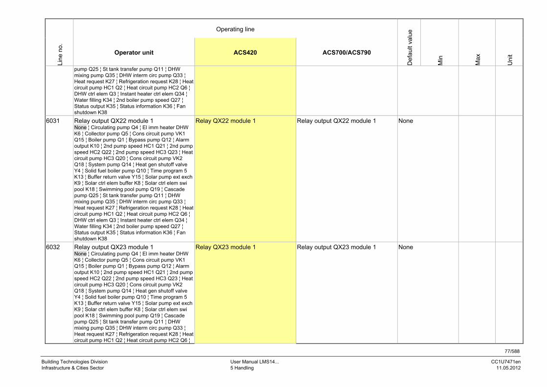
77/588
Building Technologies Division User Manual LMS14... CC1U7471en Infrastructure & Cities Sector 5 Handling 11.05.2012
Operating line
Line
no.
Operator unit ACS420 ACS700/ACS790
Def
ault
valu
e
Min
Max
Uni
t
pump Q25 ¦ St tank transfer pump Q11 ¦ DHW mixing pump Q35 ¦ DHW interm circ pump Q33 ¦ Heat request K27 ¦ Refrigeration request K28 ¦ Heat circuit pump HC1 Q2 ¦ Heat circuit pump HC2 Q6 ¦ DHW ctrl elem Q3 ¦ Instant heater ctrl elem Q34 ¦ Water filling K34 ¦ 2nd boiler pump speed Q27 ¦ Status output K35 ¦ Status information K36 ¦ Fan shutdown K38
6031 Relay output QX22 module 1 None ¦ Circulating pump Q4 ¦ El imm heater DHW K6 ¦ Collector pump Q5 ¦ Cons circuit pump VK1 Q15 ¦ Boiler pump Q1 ¦ Bypass pump Q12 ¦ Alarm output K10 ¦ 2nd pump speed HC1 Q21 ¦ 2nd pump speed HC2 Q22 ¦ 2nd pump speed HC3 Q23 ¦ Heat circuit pump HC3 Q20 ¦ Cons circuit pump VK2 Q18 ¦ System pump Q14 ¦ Heat gen shutoff valve Y4 ¦ Solid fuel boiler pump Q10 ¦ Time program 5 K13 ¦ Buffer return valve Y15 ¦ Solar pump ext exch K9 ¦ Solar ctrl elem buffer K8 ¦ Solar ctrl elem swi pool K18 ¦ Swimming pool pump Q19 ¦ Cascade pump Q25 ¦ St tank transfer pump Q11 ¦ DHW mixing pump Q35 ¦ DHW interm circ pump Q33 ¦ Heat request K27 ¦ Refrigeration request K28 ¦ Heat circuit pump HC1 Q2 ¦ Heat circuit pump HC2 Q6 ¦ DHW ctrl elem Q3 ¦ Instant heater ctrl elem Q34 ¦ Water filling K34 ¦ 2nd boiler pump speed Q27 ¦ Status output K35 ¦ Status information K36 ¦ Fan shutdown K38
Relay QX22 module 1 Relay output QX22 module 1 None
6032 Relay output QX23 module 1 None ¦ Circulating pump Q4 ¦ El imm heater DHW K6 ¦ Collector pump Q5 ¦ Cons circuit pump VK1 Q15 ¦ Boiler pump Q1 ¦ Bypass pump Q12 ¦ Alarm output K10 ¦ 2nd pump speed HC1 Q21 ¦ 2nd pump speed HC2 Q22 ¦ 2nd pump speed HC3 Q23 ¦ Heat circuit pump HC3 Q20 ¦ Cons circuit pump VK2 Q18 ¦ System pump Q14 ¦ Heat gen shutoff valve Y4 ¦ Solid fuel boiler pump Q10 ¦ Time program 5 K13 ¦ Buffer return valve Y15 ¦ Solar pump ext exch K9 ¦ Solar ctrl elem buffer K8 ¦ Solar ctrl elem swi pool K18 ¦ Swimming pool pump Q19 ¦ Cascade pump Q25 ¦ St tank transfer pump Q11 ¦ DHW mixing pump Q35 ¦ DHW interm circ pump Q33 ¦ Heat request K27 ¦ Refrigeration request K28 ¦ Heat circuit pump HC1 Q2 ¦ Heat circuit pump HC2 Q6 ¦
Relay QX23 module 1 Relay output QX23 module 1 None

78/588
Building Technologies Division User Manual LMS14... CC1U7471en Infrastructure & Cities Sector 5 Handling 11.05.2012
Operating line
Line
no.
Operator unit ACS420 ACS700/ACS790
Def
ault
valu
e
Min
Max
Uni
t
DHW ctrl elem Q3 ¦ Instant heater ctrl elem Q34 ¦ Water filling K34 ¦ 2nd boiler pump speed Q27 ¦ Status output K35 ¦ Status information K36 ¦ Fan shutdown K38
6033 Relay output QX21 module 2 None ¦ Circulating pump Q4 ¦ El imm heater DHW K6 ¦ Collector pump Q5 ¦ Cons circuit pump VK1 Q15 ¦ Boiler pump Q1 ¦ Bypass pump Q12 ¦ Alarm output K10 ¦ 2nd pump speed HC1 Q21 ¦ 2nd pump speed HC2 Q22 ¦ 2nd pump speed HC3 Q23 ¦ Heat circuit pump HC3 Q20 ¦ Cons circuit pump VK2 Q18 ¦ System pump Q14 ¦ Heat gen shutoff valve Y4 ¦ Solid fuel boiler pump Q10 ¦ Time program 5 K13 ¦ Buffer return valve Y15 ¦ Solar pump ext exch K9 ¦ Solar ctrl elem buffer K8 ¦ Solar ctrl elem swi pool K18 ¦ Swimming pool pump Q19 ¦ Cascade pump Q25 ¦ St tank transfer pump Q11 ¦ DHW mixing pump Q35 ¦ DHW interm circ pump Q33 ¦ Heat request K27 ¦ Refrigeration request K28 ¦ Heat circuit pump HC1 Q2 ¦ Heat circuit pump HC2 Q6 ¦ DHW ctrl elem Q3 ¦ Instant heater ctrl elem Q34 ¦ Water filling K34 ¦ 2nd boiler pump speed Q27 ¦ Status output K35 ¦ Status information K36 ¦ Fan shutdown K38
Relay QX21 module 2 Relay output QX21 module 2 None
6034 Relay output QX22 module 2 None ¦ Circulating pump Q4 ¦ El imm heater DHW K6 ¦ Collector pump Q5 ¦ Cons circuit pump VK1 Q15 ¦ Boiler pump Q1 ¦ Bypass pump Q12 ¦ Alarm output K10 ¦ 2nd pump speed HC1 Q21 ¦ 2nd pump speed HC2 Q22 ¦ 2nd pump speed HC3 Q23 ¦ Heat circuit pump HC3 Q20 ¦ Cons circuit pump VK2 Q18 ¦ System pump Q14 ¦ Heat gen shutoff valve Y4 ¦ Solid fuel boiler pump Q10 ¦ Time program 5 K13 ¦ Buffer return valve Y15 ¦ Solar pump ext exch K9 ¦ Solar ctrl elem buffer K8 ¦ Solar ctrl elem swi pool K18 ¦ Swimming pool pump Q19 ¦ Cascade pump Q25 ¦ St tank transfer pump Q11 ¦ DHW mixing pump Q35 ¦ DHW interm circ pump Q33 ¦ Heat request K27 ¦ Refrigeration request K28 ¦ Heat circuit pump HC1 Q2 ¦ Heat circuit pump HC2 Q6 ¦ DHW ctrl elem Q3 ¦ Instant heater ctrl elem Q34 ¦ Water filling K34 ¦ 2nd boiler pump speed Q27 ¦ Status output K35 ¦ Status information K36 ¦ Fan shutdown K38
Relay QX22 module 2 Relay output QX22 module 2 None

79/588
Building Technologies Division User Manual LMS14... CC1U7471en Infrastructure & Cities Sector 5 Handling 11.05.2012
Operating line
Line
no.
Operator unit ACS420 ACS700/ACS790
Def
ault
valu
e
Min
Max
Uni
t
6035 Relay output QX23 module 2 None ¦ Circulating pump Q4 ¦ El imm heater DHW K6 ¦ Collector pump Q5 ¦ Cons circuit pump VK1 Q15 ¦ Boiler pump Q1 ¦ Bypass pump Q12 ¦ Alarm output K10 ¦ 2nd pump speed HC1 Q21 ¦ 2nd pump speed HC2 Q22 ¦ 2nd pump speed HC3 Q23 ¦ Heat circuit pump HC3 Q20 ¦ Cons circuit pump VK2 Q18 ¦ System pump Q14 ¦ Heat gen shutoff valve Y4 ¦ Solid fuel boiler pump Q10 ¦ Time program 5 K13 ¦ Buffer return valve Y15 ¦ Solar pump ext exch K9 ¦ Solar ctrl elem buffer K8 ¦ Solar ctrl elem swi pool K18 ¦ Swimming pool pump Q19 ¦ Cascade pump Q25 ¦ St tank transfer pump Q11 ¦ DHW mixing pump Q35 ¦ DHW interm circ pump Q33 ¦ Heat request K27 ¦ Refrigeration request K28 ¦ Heat circuit pump HC1 Q2 ¦ Heat circuit pump HC2 Q6 ¦ DHW ctrl elem Q3 ¦ Instant heater ctrl elem Q34 ¦ Water filling K34 ¦ 2nd boiler pump speed Q27 ¦ Status output K35 ¦ Status information K36 ¦ Fan shutdown K38
Relay QX23 module 2 Relay output QX23 module 2 None
6036 Relay output QX21 module 3 None ¦ Circulating pump Q4 ¦ El imm heater DHW K6 ¦ Collector pump Q5 ¦ Cons circuit pump VK1 Q15 ¦ Boiler pump Q1 ¦ Bypass pump Q12 ¦ Alarm output K10 ¦ 2nd pump speed HC1 Q21 ¦ 2nd pump speed HC2 Q22 ¦ 2nd pump speed HC3 Q23 ¦ Heat circuit pump HC3 Q20 ¦ Cons circuit pump VK2 Q18 ¦ System pump Q14 ¦ Heat gen shutoff valve Y4 ¦ Solid fuel boiler pump Q10 ¦ Time program 5 K13 ¦ Buffer return valve Y15 ¦ Solar pump ext exch K9 ¦ Solar ctrl elem buffer K8 ¦ Solar ctrl elem swi pool K18 ¦ Swimming pool pump Q19 ¦ Cascade pump Q25 ¦ St tank transfer pump Q11 ¦ DHW mixing pump Q35 ¦ DHW interm circ pump Q33 ¦ Heat request K27 ¦ Refrigeration request K28 ¦ Heat circuit pump HC1 Q2 ¦ Heat circuit pump HC2 Q6 ¦ DHW ctrl elem Q3 ¦ Instant heater ctrl elem Q34 ¦ Water filling K34 ¦ 2nd boiler pump speed Q27 ¦ Status output K35 ¦ Status information K36 ¦ Fan shutdown K38
Relay QX21 module 3 Relay output QX21 module 3 None
6037 Relay output QX22 module 3 None ¦ Circulating pump Q4 ¦ El imm heater DHW K6 ¦ Collector pump Q5 ¦ Cons circuit pump VK1 Q15 ¦ Boiler pump Q1 ¦ Bypass pump Q12 ¦ Alarm
Relay QX22 module 3 Relay output QX22 module 3 None

80/588
Building Technologies Division User Manual LMS14... CC1U7471en Infrastructure & Cities Sector 5 Handling 11.05.2012
Operating line
Line
no.
Operator unit ACS420 ACS700/ACS790
Def
ault
valu
e
Min
Max
Uni
t
output K10 ¦ 2nd pump speed HC1 Q21 ¦ 2nd pump speed HC2 Q22 ¦ 2nd pump speed HC3 Q23 ¦ Heat circuit pump HC3 Q20 ¦ Cons circuit pump VK2 Q18 ¦ System pump Q14 ¦ Heat gen shutoff valve Y4 ¦ Solid fuel boiler pump Q10 ¦ Time program 5 K13 ¦ Buffer return valve Y15 ¦ Solar pump ext exch K9 ¦ Solar ctrl elem buffer K8 ¦ Solar ctrl elem swi pool K18 ¦ Swimming pool pump Q19 ¦ Cascade pump Q25 ¦ St tank transfer pump Q11 ¦ DHW mixing pump Q35 ¦ DHW interm circ pump Q33 ¦ Heat request K27 ¦ Refrigeration request K28 ¦ Heat circuit pump HC1 Q2 ¦ Heat circuit pump HC2 Q6 ¦ DHW ctrl elem Q3 ¦ Instant heater ctrl elem Q34 ¦ Water filling K34 ¦ 2nd boiler pump speed Q27 ¦ Status output K35 ¦ Status information K36 ¦ Fan shutdown K38
6038 Relay output QX23 module 3 None ¦ Circulating pump Q4 ¦ El imm heater DHW K6 ¦ Collector pump Q5 ¦ Cons circuit pump VK1 Q15 ¦ Boiler pump Q1 ¦ Bypass pump Q12 ¦ Alarm output K10 ¦ 2nd pump speed HC1 Q21 ¦ 2nd pump speed HC2 Q22 ¦ 2nd pump speed HC3 Q23 ¦ Heat circuit pump HC3 Q20 ¦ Cons circuit pump VK2 Q18 ¦ System pump Q14 ¦ Heat gen shutoff valve Y4 ¦ Solid fuel boiler pump Q10 ¦ Time program 5 K13 ¦ Buffer return valve Y15 ¦ Solar pump ext exch K9 ¦ Solar ctrl elem buffer K8 ¦ Solar ctrl elem swi pool K18 ¦ Swimming pool pump Q19 ¦ Cascade pump Q25 ¦ St tank transfer pump Q11 ¦ DHW mixing pump Q35 ¦ DHW interm circ pump Q33 ¦ Heat request K27 ¦ Refrigeration request K28 ¦ Heat circuit pump HC1 Q2 ¦ Heat circuit pump HC2 Q6 ¦ DHW ctrl elem Q3 ¦ Instant heater ctrl elem Q34 ¦ Water filling K34 ¦ 2nd boiler pump speed Q27 ¦ Status output K35 ¦ Status information K36 ¦ Fan shutdown K38
Relay QX23 module 3 Relay output QX23 module 3 None
6040 Sensor input BX21 module 1 None ¦ DHW sensor B31 ¦ Collector sensor B6 ¦ DHW circulation sensor B39 ¦ Buffer sensor B4 ¦ Buffer sensor B41 ¦ Flue gas temp sensor B8 ¦ Common flow sensor B10 ¦ Solid fuel boiler sensor B22 ¦ DHW charging sensor B36 ¦ Buffer sensor B42 ¦ Common return sensor B73 ¦ Cascade return sensor B70 ¦ Swimming pool sensor B13 ¦ Solar flow sensor B63 ¦
Sensor BX21 module 1 Sensor input BX21 module 1 None

81/588
Building Technologies Division User Manual LMS14... CC1U7471en Infrastructure & Cities Sector 5 Handling 11.05.2012
Operating line
Line
no.
Operator unit ACS420 ACS700/ACS790
Def
ault
valu
e
Min
Max
Uni
t
Solar return sensor B64 ¦ Primary exch sensor B26
6041 Sensor input BX22 module 1 None ¦ DHW sensor B31 ¦ Collector sensor B6 ¦ DHW circulation sensor B39 ¦ Buffer sensor B4 ¦ Buffer sensor B41 ¦ Flue gas temp sensor B8 ¦ Common flow sensor B10 ¦ Solid fuel boiler sensor B22 ¦ DHW charging sensor B36 ¦ Buffer sensor B42 ¦ Common return sensor B73 ¦ Cascade return sensor B70 ¦ Swimming pool sensor B13 ¦ Solar flow sensor B63 ¦ Solar return sensor B64 ¦ Primary exch sensor B26
Sensor BX22 module 1 Sensor input BX22 module 1 None
6042 Sensor input BX21 module 2 None ¦ DHW sensor B31 ¦ Collector sensor B6 ¦ DHW circulation sensor B39 ¦ Buffer sensor B4 ¦ Buffer sensor B41 ¦ Flue gas temp sensor B8 ¦ Common flow sensor B10 ¦ Solid fuel boiler sensor B22 ¦ DHW charging sensor B36 ¦ Buffer sensor B42 ¦ Common return sensor B73 ¦ Cascade return sensor B70 ¦ Swimming pool sensor B13 ¦ Solar flow sensor B63 ¦ Solar return sensor B64 ¦ Primary exch sensor B26
Sensor BX21 module 2 Sensor input BX21 module 2 None
6043 Sensor input BX22 module 2 None ¦ DHW sensor B31 ¦ Collector sensor B6 ¦ DHW circulation sensor B39 ¦ Buffer sensor B4 ¦ Buffer sensor B41 ¦ Flue gas temp sensor B8 ¦ Common flow sensor B10 ¦ Solid fuel boiler sensor B22 ¦ DHW charging sensor B36 ¦ Buffer sensor B42 ¦ Common return sensor B73 ¦ Cascade return sensor B70 ¦ Swimming pool sensor B13 ¦ Solar flow sensor B63 ¦ Solar return sensor B64 ¦ Primary exch sensor B26
Sensor BX22 module 2 Sensor input BX22 module 2 None
6044 Sensor input BX21 module 3 None ¦ DHW sensor B31 ¦ Collector sensor B6 ¦ DHW circulation sensor B39 ¦ Buffer sensor B4 ¦ Buffer sensor B41 ¦ Flue gas temp sensor B8 ¦ Common flow sensor B10 ¦ Solid fuel boiler sensor B22 ¦ DHW charging sensor B36 ¦ Buffer sensor B42 ¦ Common return sensor B73 ¦ Cascade return sensor B70 ¦ Swimming pool sensor B13 ¦ Solar flow sensor B63 ¦ Solar return sensor B64 ¦ Primary exch sensor B26
Sensor BX21 module 3 Sensor input BX21 module 3 None
6045 Sensor input BX22 module 3 None ¦ DHW sensor B31 ¦ Collector sensor B6 ¦ DHW circulation sensor B39 ¦ Buffer sensor B4 ¦ Buffer sensor B41 ¦ Flue gas temp sensor B8 ¦ Common flow sensor B10 ¦ Solid fuel boiler sensor B22 ¦ DHW charging sensor B36 ¦ Buffer sensor B42 ¦ Common
Sensor BX22 module 3 Sensor input BX22 module 3 None

82/588
Building Technologies Division User Manual LMS14... CC1U7471en Infrastructure & Cities Sector 5 Handling 11.05.2012
Operating line
Line
no.
Operator unit ACS420 ACS700/ACS790
Def
ault
valu
e
Min
Max
Uni
t
return sensor B73 ¦ Cascade return sensor B70 ¦ Swimming pool sensor B13 ¦ Solar flow sensor B63 ¦ Solar return sensor B64 ¦ Primary exch sensor B26
6046 Function of input H2 module 1 None ¦ Optg mode change HCs+DHW ¦ Optg mode changeover DHW ¦ Optg mode changeover HCs ¦ Optg mode changeover HC1 ¦ Optg mode changeover HC2 ¦ Optg mode changeover HC3 ¦ Heat generation lock ¦ Error/alarm message ¦ Consumer request VK1 ¦ Consumer request VK2 ¦ Release swi pool generator ¦ Excess heat discharge ¦ Release swi pool solar ¦ Operating level DHW ¦ Operating level HC1 ¦ Operating level HC2 ¦ Operating level HC3 ¦ Room thermostat HC1 ¦ Room thermostat HC2 ¦ Room thermostat HC3 ¦ DHW flow switch ¦ DHW thermostat ¦ Limit thermostat HC ¦ Start prevention ¦ Boiler flow switch ¦ Boiler pressure switch ¦ Consumer request VK1 10V ¦ Consumer request VK2 10V ¦ Pressure measurement 10V ¦ Output request 10V
Function H2 module 1 Function input H2 module 1 None
6047 Contact type H2 module 1 NC ¦ NO
Contact type H2 mod1 Contact type H2 module 1 NO -
6049 Voltage value 1 H2 module 1 VoltageValue1 H2 mod1 Voltage value 1 H2 module 1 0 0 10 Volt
6050 Function value 1 H2 module 1 Funct value 1 H2 mod1 Funct value 1 H2 module 1 0 -1000 5000 -
6051 Voltage value 2 H2 module 1 VoltageValue2 H2 mod1 Voltage value 2 H2 module 1 0 0 10 Volt
6052 Function value 2 H2 module 1 Funct value 2 H2 mod1 Funct value 2 H2 module 1 0 -1000 5000 -
6054 Function of input H2 module 2 None ¦ Optg mode change HCs+DHW ¦ Optg mode changeover DHW ¦ Optg mode changeover HCs ¦ Optg mode changeover HC1 ¦ Optg mode changeover HC2 ¦ Optg mode changeover HC3 ¦ Heat generation lock ¦ Error/alarm message ¦ Consumer request VK1 ¦ Consumer request VK2 ¦ Release swi pool generator ¦ Excess heat discharge ¦ Release swi pool solar ¦ Operating level DHW ¦ Operating level HC1 ¦ Operating level HC2 ¦ Operating level HC3 ¦ Room thermostat HC1 ¦ Room thermostat HC2 ¦ Room thermostat HC3 ¦ DHW flow switch ¦ DHW thermostat ¦ Limit thermostat HC ¦ Start prevention ¦ Boiler flow switch ¦ Boiler pressure switch ¦ Consumer request VK1 10V ¦ Consumer request VK2 10V ¦ Pressure
Function H2 module2 Function input H2 module 2 None

83/588
Building Technologies Division User Manual LMS14... CC1U7471en Infrastructure & Cities Sector 5 Handling 11.05.2012
Operating line
Line
no.
Operator unit ACS420 ACS700/ACS790
Def
ault
valu
e
Min
Max
Uni
t
measurement 10V ¦ Output request 10V
6055 Contact type H2 module 2 NC ¦ NO
Contact type H2 mod2 Contact type H2 module 2 NO -
6057 Voltage value 1 H2 module 2 VoltageValue1 H2 mod2 Voltage value 1 H2 module 2 0 0 10 Volt
6058 Funct value 1 H2 module 2 Funct value 1 H2 mod2 Funct value 1 H2 module 2 0 -1000 5000 -
6059 Voltage value 2 H2 Module 2 VoltageValue2 H2 mod2 Voltage value 2 H2 module 2 0 0 10 Volt
6060 Funct value 2 H2 module 2 Funct value 2 H2 mod2 Funct value 2 H2 module 2 0 -1000 5000 -
6062 Function of input H2 module 3 None ¦ Optg mode change HCs+DHW ¦ Optg mode changeover DHW ¦ Optg mode changeover HCs ¦ Optg mode changeover HC1 ¦ Optg mode changeover HC2 ¦ Optg mode changeover HC3 ¦ Heat generation lock ¦ Error/alarm message ¦ Consumer request VK1 ¦ Consumer request VK2 ¦ Release swi pool generator ¦ Excess heat discharge ¦ Release swi pool solar ¦ Operating level DHW ¦ Operating level HC1 ¦ Operating level HC2 ¦ Operating level HC3 ¦ Room thermostat HC1 ¦ Room thermostat HC2 ¦ Room thermostat HC3 ¦ DHW flow switch ¦ DHW thermostat ¦ Limit thermostat HC ¦ Start prevention ¦ Boiler flow switch ¦ Boiler pressure switch ¦ Consumer request VK1 10V ¦ Consumer request VK2 10V ¦ Pressure measurement 10V ¦ Output request 10V
Function H2 module3 Function input H2 module 3 None
6063 Contact type H2 module 3 NC ¦ NO
Contact type H2 mod 3 Contact type H2 module 3 NO -
6065 Voltage value 1 H2 module 3 VoltageValue1 H2 mod3 Voltage value 1 H2 module 3 0 0 10 Volt
6066 Funct value 1 H2 module 3 Fctn value 1 H2 mod3 Funct value 1 H2 module 3 0 -1000 5000 -
6067 Voltage value 2 H2 module 3 VoltageValue2 H2 mod3 Voltage value 2 H2 module 3 0 0 10 Volt
6068 Funct value 2 H2 module 3 Fctn value 2 H2 mod3 Funct value 2 H2 module 3 0 -1000 5000 -
6085 Function output P1 None ¦ Boiler pump Q1 ¦ DHW pump Q3 ¦ DHW interm circ pump Q33 ¦ Heat circuit pump HC1 Q2 ¦ Heat circuit pump HC2 Q6 ¦ Heat circuit pump HC3 Q20 ¦ Collector pump Q5 ¦ Solar pump ext exch K9 ¦ Solar pump buffer K8 ¦ Solar pump swi pool K18 ¦ Instant WH pump Q34
P1 FctnSel Output P1 function selection None
6097 Sensor type collector NTC ¦ Pt 1000
Sensor type collector Sensor type collector NTC

84/588
Building Technologies Division User Manual LMS14... CC1U7471en Infrastructure & Cities Sector 5 Handling 11.05.2012
Operating line
Line
no.
Operator unit ACS420 ACS700/ACS790
Def
ault
valu
e
Min
Max
Uni
t
6098 Readjustm collector sensor ValCorr CollTemp 1 Measured value corr collector sensor 1 (B6)
0 -20 20 °C
6100 Readjustm outside sensor OT readjustment Outside temp sensor measuring readjustment
0 -3.0 3.0 °C
6101 Sensor type flue gas temp NTC ¦ Pt 1000 ¦ NTC 20k
Sensor type flue gas Sensor type flue gas temperature NTC
6102 Readjustm flue gas sensor ValCorr FlueGasTemp Measured value corr flue gas sensor (B8)
0 -20 20 °C
6110 Time constant building Building time const Building time constant 15 0 50 h
6116 Time constant setp compens TimeConstSetpCompens Time constant setpoint compensation
0 0 14 Min.
6117 Central setp compensation CentralSetpShift Central setpoint shift 20 / 1 100 °C
6118 Setpoint drop delay Setp reduct delay Setpoint reduction delay / 1 200 °C
6120 Frost protection plant Off ¦ On
FrostProtection plant Frost protection for the plant Off -
6127 Pump/valve kick duration Pump/valve kick dur Pump/valve kick duration 30 0 51 s
6140 Water pressure max Water pressure max Water pressure max 3 / 0,0 10,0 bar
6141 Water pressure min Water pressure min Water pressure min 0,8 / 0,0 10,0 bar
6142 Water pressure critical min Water pressure crit min Water pressure critical min 0,5 / 0,0 10,0 bar
6143 Water pressure SD Water pressure switching differential 0,3 0,0 10,0 bar
6150 Water pressure 2 max Water pressure 2 max Water pressure 2 max 3 / 0,0 10,0 bar
6151 Water pressure 2 min Water pressure 2 min Water pressure 2 min 0,8 / 0,0 10,0 bar
6152 Water press 2 critical min Water pressure 2 crit min Water pressure 2 critical min 0,5 / 0,0 10,0 bar
6153 Water pressure 2 SD Water pressure 2 switching differential
0,3 0,0 10,0 bar
6180 Water pressure 3 max Water pressure 3 max Water pressure 3 max 3 / 0,0 10,0 bar
6181 Water pressure 3 min Water pressure 3 min Water pressure 3 min 0,8 / 0,0 10,0 bar
6182 Water press 3 critical min Water pressure 3 crit min Water pressure 3 critical min 0,5 / 0,0 10,0 bar
6183 Water pressure 3 SD Water pressure 3 switching differential
0,3 0,0 10,0 bar
6200 Save sensors No ¦ Yes
Store sensor Store sensor None -

85/588
Building Technologies Division User Manual LMS14... CC1U7471en Infrastructure & Cities Sector 5 Handling 11.05.2012
Operating line
Line
no.
Operator unit ACS420 ACS700/ACS790
Def
ault
valu
e
Min
Max
Uni
t
6204 Save parameters No ¦ Yes
Store parameter Store parameter None -
6205 Reset to default parameters No ¦ Yes
Reset parameter Reset parameter None -
6212 Check no. heat source 1 CtrlNumber source 1 Control number heat generation 1 - 0 199999 -
6213 Check no. heat source 2 CtrlNumber source 2 Control number heat generation 2 - 0 199999 -
6215 Check no. storage tank CtrlNumber storage Control number storage tank - 0 199999 -
6217 Check no. heating circuits CtrlNumber HCs Control number heating circuits - 0 199999 -
6220 Software version Device SW version Device SW version - 0 99 -
6221 Development index Development index Development index - 0 99 -
6224 Device identification Device identification LMS14.xxxxk09
6225 Device family Device family
6226 Device variant Device variant -
6227 Object directory version Object directory version -
6230 Info 1 OEM Info 1 OEM Info 1 OEM -
6231 Info 2 OEM Info 2 OEM Info 2 OEM -
6232 Parameter version Parameter version -
6233 Parameter set number Parameter set number -
6234 Boiler type number OEM Boiler type number OEM -
6235 Parameter set group OEM Parameter set group OEM -
6236 Parameter set number OEM Parameter set number OEM -
[1564.1] PartDiagram oil/gas Partial diagram oil/gas-fired boiler - 0 255
[1565.1] PartDiagram solar Partial diagram solar collector - 0 255
[1566.1] PartDiagram HC1 Partial diagram heat circuit 1 - 0 255
[1566.2] PartDiagram HC2 Partial diagram heat circuit 2 - 0 255
[1566.3] PartDiagram HC3 Partial diagram heat circuit 3 - 0 255
[1567.1] PartDiagram buffer Partial diagram buffer storage tank - 0 255
[1568.1] PartDiagram DHW Partial diagram DHW storage tank - 0 255
[1984.1] PartDiagram HeatExch Partial diagram heat exchanger - 0 255
[1563.1] PartDiagram SolidFuel Partial diagram solid fuel boiler - 0 255
[2090.1] PartDiagram SwiPool Partial diagram swimming pool - 0 255
[2835.1] PartDiagramHydrBalanc Partial diagram hydraulic balancing - 0 255

86/588
Building Technologies Division User Manual LMS14... CC1U7471en Infrastructure & Cities Sector 5 Handling 11.05.2012
Operating line
Line
no.
Operator unit ACS420 ACS700/ACS790
Def
ault
valu
e
Min
Max
Uni
t
[2836.1] PartDiagram instWH Partial diagram instantaneous water heater
- 0 255
[4365.1] PartDiagram ConsC1 Partial diagram consumer circuit 1 - 0 255
[4365.2] PartDiagram ConsC2 Partial diagram consumer circuit 2 - 0 255
[4365.3] PartDiagram SwiPool Partial diagram swimming pool circuit
- 0 255
[2748.1] Cascade status
Inactive ¦ Active
Cascade status Inactive
LPB system
6600 * LPB address S0/G1 S0/G1 S14/G16 -
6600 * Device address Device address 1 0 16 -
6601 * Segment address Segment address 0 0 14 -
* Depending on operating tool, either one operating line with LPB address or 2 operating lines with separate device and segment address
6604 Bus power supply function Off ¦ Automatically
LPB PowSup Fctn Sel LPB power supply function selection Automatically -
6605 Bus power supply state Off ¦ On
LPB PowSup state LPB power supply state On -
6610 Display system messages No ¦ Yes
Display system message Display system message Yes
6612 Alarm delay Alarm delay Alarm delay / 2 60 Min.
6620 Action changeover functions Segment ¦ System
CentrSwitch-OverArea Central switch-over working area System -
6621 Summer changeover Locally¦ Centrally
Su/Wi changeover Summer/winter changeover automatic
Locally -
6623 Optg mode changeover Locally ¦ Centrally
OptgMode Ch’over Operating mode changeover Centrally
6624 Manual source lock Locally ¦ Segment
Man source lock Manual source lock Locally
6625 DHW assignment Local HCs ¦ All HCs in segment ¦ All HCs in system
DHW allocation DHW allocation All HCs in system -
6630 Cascade master Cascade master Cascade master Automatically

87/588
Building Technologies Division User Manual LMS14... CC1U7471en Infrastructure & Cities Sector 5 Handling 11.05.2012
Operating line
Line
no.
Operator unit ACS420 ACS700/ACS790
Def
ault
valu
e
Min
Max
Uni
t
Always ¦ Automatically
6631 Ext source with eco mode Off ¦ On DHW ¦ On
ExtSource withEcoMode Ext source with eco mode Off
6632 Note OT limit ext source No ¦ Yes
OT lim ext sou accept Outside temp limit external source accept
No
6640 Clock mode Autonomously ¦ Slave without remote ¦ Slave with remote setting ¦ Master
Clock time source Clock time source Autonomously -
6650 Outside temp source Outside temp source Outside temp source S0/G1 S0/G1 S14/G16 -
Fault
6700 Message Error signal Error signal -
6705 SW diagnostic code Diagnostic code Internal value of diagnostic code -
6706 Burn ctrl phase lockout pos StrPn_akt Current value of lockout phase -
6710 Reset alarm relay No ¦ Yes
Reset Alarm Relay Reset alarm relay No
6740 Flow temp 1 alarm TimeFlowTempAlarm HC1 Time flow temperature alarm HC1 / 10 240 Min.
6741 Flow temp 2 alarm TimeFlowTempAlarm HC2 Time flow temperature alarm HC2 / 10 240 Min.
6742 Flow temp 3 alarm TimeFlowTempAlarm HC3 Time flow temperature alarm HC3 / 10 240 Min.
6743 Boiler temp alarm Time BoilerTempAlarm Time boiler temperature alarm / 10 240 Min.
6745 DHW charging alarm Time DHWChargingAlarm Time DHW charging alarm / 1 48 h
6800 History 1 Time ErrorHistory 1 Time stamp error history entry 1 -
6803 Error code 1 ErrorCode History 1 Error code history entry 1 - 0 65535 -
6805 SW diagnostic code 1 StrDia1 Historical value 1 of internal diagnostic code
- 0 65535 -
6806 Burner control phase 1 StrPn1 Historical value 1 of lockout phase - 0 255 -
6810 History 2 Time ErrorHistory 2 Time stamp error history entry 2 -
6813 Error code 2 ErrorCode History 2 Error code history entry 2 - 0 65535 -
6815 SW diagnostic code 2 StrDia2 Historical value 2 of internal diagnostic code
- 0 65535 -
6816 Burner control phase 2 StrPn2 Historical value 2 of lockout phase - 0 255 -
6820 History 3 Time ErrorHistory 3 Time stamp error history entry 3 -
6823 Error code 3 ErrorCode History 3 Error code history entry 3 - 0 65535 -
6825 SW diagnostic code 3 StrDia3 Historical value 3 of internal - 0 65535 -

88/588
Building Technologies Division User Manual LMS14... CC1U7471en Infrastructure & Cities Sector 5 Handling 11.05.2012
Operating line
Line
no.
Operator unit ACS420 ACS700/ACS790
Def
ault
valu
e
Min
Max
Uni
t
diagnostic code
6826 Burner control phase 3 StrPn3 Historical value 3 of lockout phase - 0 255 -
6830 History 4 Time ErrorHistory 4 Time stamp error history entry 4 -
6833 Error code 4 ErrorCode History 4 Error code history entry 4 - 0 65535 -
6835 SW diagnostic code 4 StrDia4 Historical value 4 of internal diagnostic code
- 0 65535 -
6836 Burner control phase 4 StrPn4 Historical value 4 of lockout phase - 0 255 -
6840 History 5 Time ErrorHistory 5 Time stamp error history entry 5 -
6843 Error code 5 ErrorCode History 5 Error code history entry 5 - 0 65535 -
6845 SW diagnostic code 5 StrDia5 Historical value 5 of internal diagnostic code
- 0 65535 -
6846 Burner control phase 5 StrPn5 Historical value 5 of lockout phase - 0 255 -
6850 History 6 Time ErrorHistory 6 Time stamp error history entry 6 -
6853 Error code 6 ErrorCode History 6 Error code history entry 6 - 0 65535 -
6855 SW diagnostic code 6 StrDia6 Historical value 6 of lockout diagnostics
- 0 65535 -
6856 Burner control phase 6 StrPn6 Historical value 6 of lockout phase - 0 255 -
6860 History 7 Time ErrorHistory 7 Time stamp error history entry 7 -
6863 Error code 7 ErrorCode History 7 Error code history entry 7 - 0 65535 -
6865 SW diagnostic code 7 StrDia7 Historical value 7 of lockout diagnostics
- 0 65535 -
6866 Burner control phase 7 StrPn7 Historical value 7 of lockout phase - 0 255 -
6870 History 8 Time ErrorHistory 8 Time stamp error history entry 8 -
6873 Error code 8 ErrorCode History 8 Error code history entry 8 - 0 65535 -
6875 SW diagnostic code 8 StrDia8 Historical value 8 of lockout diagnostics
- 0 65535 -
6876 Burner control phase 8 StrPn8 Historical value 8 of lockout phase - 0 255 -
6880 History 9 Time ErrorHistory 9 Time stamp error history entry 9 -
6883 Error code 9 ErrorCode History 9 Error code history entry 9 - 0 65535 -
6885 SW diagnostic code 9 StrDia9 Historical value 9 of lockout diagnostics
- 0 65535 -
6886 Burner control phase 9 StrPn9 Historical value 9 of lockout phase - 0 255 -

89/588
Building Technologies Division User Manual LMS14... CC1U7471en Infrastructure & Cities Sector 5 Handling 11.05.2012
Operating line
Line
no.
Operator unit ACS420 ACS700/ACS790
Def
ault
valu
e
Min
Max
Uni
t
6890 History 10 Time ErrorHistory 10 Time stamp error history entry 10 -
6893 Error code 10 ErrorCode History 10 Error code history entry 10 - 0 65535 -
6895 SW diagnostic code 10 StrDia10 Historical value 10 of lockout diagnostics
- 0 65535 -
6896 Burner control phase 10 StrPn10 Historical value 10 of lockout phase - 0 255 -
6900 History 11 Time ErrorHistory 11 Time stamp error history entry 11 -
6903 Error code 11 ErrorCode History 11 Error code history entry 11 - 0 65535 -
6905 SW diagnostic code 11 StrDia11 Historical value 11 of lockout diagnostics
- 0 65535 -
6906 Burner control phase 11 StrPn11 Historical value 11 of lockout phase - 0 255 -
6910 History 12 Time ErrorHistory 12 Time stamp error history entry 12 -
6913 Error code 12 ErrorCode History 12 Error code history entry 12 - 0 65535 -
6915 SW diagnostic code 12 StrDia12 Historical value 12 of lockout diagnostics
- 0 65535 -
6916 Burner control phase 12 StrPn12 Historical value 12 of lockout phase - 0 255 -
6920 History 13 Time ErrorHistory 13 Time stamp error history entry 13 -
6923 Error code 13 ErrorCode History 13 Error code history entry 13 - 0 65535 -
6925 SW diagnostic code 13 StrDia13 Historical value 13 of lockout diagnostics
- 0 65535 -
6926 Burner control phase 13 StrPn13 Historical value 13 of lockout phase - 0 255 -
6930 History 14 Time ErrorHistory 14 Time stamp error history entry 14 -
6933 Error code 14 ErrorCode History 14 Error code history entry 14 - 0 65535 -
6935 SW diagnostic code 14 StrDia14 Historical value 14 of lockout diagnostics
- 0 65535 -
6936 Burner control phase 14 StrPn14 Historical value 14 of lockout phase - 0 255 -
6940 History 15 Time ErrorHistory 15 Time stamp error history entry 15 -
6943 Error code 15 ErrorCode History 15 Error code history entry 15 - 0 65535 -
6945 SW diagnostic code 15 StrDia15 Historical value 15 of lockout diagnostics
- 0 65535 -
6946 Burner control phase 15 StrPn15 Historical value 15 of lockout phase - 0 255 -
6950 History 16 Time ErrorHistory 16 Time stamp error history entry 16 -
6953 Error code 16 ErrorCode History 16 Error code history entry 16 - 0 65535 -

90/588
Building Technologies Division User Manual LMS14... CC1U7471en Infrastructure & Cities Sector 5 Handling 11.05.2012
Operating line
Line
no.
Operator unit ACS420 ACS700/ACS790
Def
ault
valu
e
Min
Max
Uni
t
6955 SW diagnostic code 16 StrDia16 Historical value 16 of lockout diagnostics
- 0 65535 -
6956 Burner control phase 16 StrPn16 Historical value 16 of lockout phase - 0 255 -
6960 History 17 Time ErrorHistory 17 Time stamp error history entry 17 -
6963 Error code 17 ErrorCode History 17 Error code history entry 17 - 0 65535 -
6965 SW diagnostic code 17 StrDia17 Historical value 17 of lockout diagnostics
- 0 65535 -
6966 Burner control phase 17 StrPn17 Historical value 17 of lockout phase - 0 255 -
6970 History 18 Time ErrorHistory 18 Time stamp error history entry 18 -
6973 Error code 18 ErrorCode History 18 Error code history entry 18 - 0 65535 -
6975 SW diagnostic code 18 StrDia18 Historical value 18 of lockout diagnostics
- 0 65535 -
6976 Burner control phase 18 StrPn18 Historical value 18 of lockout phase - 0 255 -
6980 History 19 Time ErrorHistory 19 Time stamp error history entry 19 -
6983 Error code 19 ErrorCode History 19 Error code history entry 19 - 0 65535 -
6985 SW diagnostic code 19 StrDia19 Historical value 19 of lockout diagnostics
- 0 65535 -
6986 Burner control phase 19 StrPn19 Historical value 19 of lockout phase - 0 255 -
6990 History 20 Time ErrorHistory 20 Time stamp error history entry 20 -
6993 Error code 20 ErrorCode History 20 Error code history entry 20 - 0 65535 -
6995 SW diagnostic code 20 StrDia20 Historical value 20 of lockout diagnostics
- 0 65535 -
6996 Burner control phase 20 StrPn20 Historical value 20 of lockout phase - 0 255 -
6999 Reset history No ¦ Yes
Reset ErrorHistory Reset error history No -
Maintenance/special operation
7040 Burner hours interval BurnHours MaintInt Burner hours run maintenance interval
/ 100 10000 h
7041 Burner hrs since maintenance BurnHours sinceMaint Burner hours run since maintenance 0 0 10000 h
7042 Burner start interval BurnStarts MaintInt Burner starts maintenance interval / 100 65500 -
7043 Burner starts since maint BurnStarts sinceMaint Burner starts since maintenance 0 0 65535 -
7044 Maintenance interval Maintenance Interval Maintenance interval / 1 240 Months

91/588
Building Technologies Division User Manual LMS14... CC1U7471en Infrastructure & Cities Sector 5 Handling 11.05.2012
Operating line
Line
no.
Operator unit ACS420 ACS700/ACS790
Def
ault
valu
e
Min
Max
Uni
t
7045 Time since maintenance Time sinceMaint Time since maintenance 0 0 240 Months
7050 Fan speed ionization current FanSp ServiceThresh Fan speed threshold for service message
0 0 10000 min-1
7051 Message ionization current
No ¦ Yes
IonCurr ServMessage Ionization current service message No
7130 Chimney sweep function Off ¦ On
ChimneySweep function Chimney sweep function Off -
7131 Burner output Partial load ¦ Full load
Chimney BurnerOutput Chimney sweep function burner output
Full load -
7140 Manual control Off ¦ On
Manual operation Manual operation Off -
7143 Controller stop function Off ¦ On
Contr stop function Controller stop function Off -
7145 Controller stop setpoint Controller stop setpoint Controller stop setpoint 50 0 100 %
7146 Deaeration function Off ¦ On
Deaeration function Deaeration function On -
7147 Type of venting None ¦ Heating circuit continuous ¦ Heating circuit cycled ¦ DHW continuous ¦ DHW cycled
Type of venting Type of venting None -
7170 Telephone customer service 0 0 9
7250 PStick storage pos PStick storage pos PStick storage pos 0 0 250 -
7251 Pstick data description -
7252 PStick command No operation ¦ Reading from stick ¦ Writing on stick
PStick command PStick command No operation
7253 PStick progress PStick progress PStick progress 0 0 100 %
7254 PStick status PStick state
No stick ¦ Stick ready ¦ Writing on stick ¦
Reading from stick ¦ EMC test active ¦
Writing error ¦ Reading error ¦ Incompatible
data set ¦ Wrong stick type ¦ Stick format
error ¦ Check data set ¦ Data set disabled ¦
Reading disabled
No stick
[4566.1] PStick series number Series number of parameter stick used last
0 0 4294967295 -

92/588
Building Technologies Division User Manual LMS14... CC1U7471en Infrastructure & Cities Sector 5 Handling 11.05.2012
Operating line
Line
no.
Operator unit ACS420 ACS700/ACS790
Def
ault
valu
e
Min
Max
Uni
t
[4693.1] PStick storage location PStick storage location 0 0 250 -
[4733.1] OEM PStickDataSetNo OEM PStick data set number 0 0 65535 -
[4734.1] HQ PStickDataSetNo HQ PStick data set number 0 0 65535 -
Input/output test
7700 Relay test No test ¦ Everything off ¦ Relay output QX1 ¦ Relay
output QX2 ¦ Relay output QX3 ¦ Relay output QX4
¦ Relay output QX21 module 1 ¦ Relay output QX22
module 1 ¦ Relay output QX23 module 1 ¦ Relay
output QX21 module 2 ¦ Relay output QX22 module
2 ¦ Relay output QX23 module 2 ¦ Relay output
QX21 module 3 ¦ Relay output QX22 module 3 ¦
Relay output QX23 module 3
Relay test Relay test No test -
7713 Output test P1 Output test P1 - - - - - - / 0 100 %
7714 PWM output P1 PWM output P1 - 0 100 %
7730 Outside temp B9 Outside temp B9 Outside temperature B9 - -50 50 °C
7750 DHW temp B3/B38 DHW temp B3/B38 DHW temp B3/B38 - 0 140 °C
7760 Boiler temp B2 Boiler temp B2 Boiler temperature B2 - 0 140 °C
7820 Sensor temp BX1 Sensor temp BX1 Sensor temperature BX1 - -28 350 °C
7821 Sensor temp BX2 Sensor temp BX2 Sensor temperature BX2 - -28 350 °C
7822 Sensor temp BX3 Sensor temp BX3 Sensor temperature BX3 - -28 350 °C
7823 Sensor temp BX4 Sensor temp BX4 Sensor temperature BX4 - -28 350 °C
7830 Sensor temp BX21 module 1 Temp BX21 module 1 Sensor temperature BX21 module 1 - -28 350 °C
7831 Sensor temp BX22 module 1 Temp BX22 modul 1 Sensor temperature BX22 module 1 - -28 350 °C
7832 Sensor temp BX21 module 2 Temp BX21 modul 1 Sensor temperature BX21 module 2 - -28 350 °C
7833 Sensor temp BX22 module 2 Temp BX22 modul 1 Sensor temperature BX22 module 2 - -28 350 °C
7834 Sensor temp BX21 module 3 Temp BX21 modul 3 Sensor temperature BX21 module 3 - -28 350 °C
7835 Sensor temp BX22 module 3 Temp BX22 modul 3 Sensor temperature BX22 module 3 - -28 350 °C
7840 Voltage signal H1 Voltage signal H1 Voltage signal H1 - 0 10 V-
7841 Contact state H1
Open ¦ Closed
Contact state H1 Contact state H1 Open
7845 Voltage signal H2 module 1 Voltage sig H2 mod1 Voltage signal H2 module 1 - 0 10 V

93/588
Building Technologies Division User Manual LMS14... CC1U7471en Infrastructure & Cities Sector 5 Handling 11.05.2012
Operating line
Line
no.
Operator unit ACS420 ACS700/ACS790
Def
ault
valu
e
Min
Max
Uni
t
7846 Contact state H2 module 1
Open ¦ Closed
Contact state H2 mod1 Contact state H2 module 1 Open
7848 Voltage signal H2 module 2 Voltage sig H2 mod2 Voltage signal H2 module 2 - 0 10 V
7849 Contact state H2 module 2
Open ¦ Closed
Contact state H2 mod2 Contact state H2 module 2 Open
7851 Voltage signal H2 module 3 Voltage sig H2 mod3 Voltage signal H2 module 3 - 0 10 V
7852 Contact state H2 module 3
Open ¦ Closed
Contact state H2 mod3 Contact state H2 module 3 Open -
7854 Voltage signal H3 Voltage signal H3 Voltage signal H3 - 0 10 V
7855 Contact state H3 Contact state H3 Contact state H3 Open
7860 Contact state H4
Open ¦ Closed
Contact state H4 Contact state H4 Open
7862 Frequency H4 Frequency H4 Frequency H4 - 0 2000
7865 Contact state H5
Open ¦ Closed
Contact state H5 Contact state H5 Open
7872 Contact state H6
Open ¦ Closed
Contact state H6 Contact state H6 Open
7874 Contact state H7
Open ¦ Closed
Contact state H7 Contact state H7 Open
7950 Input EX21 module 1
0V ¦ 230V
Inputl EX21 module 1 Input EX21 module 1 0V -
7951 Input EX21 module 2
0V ¦ 230V
Inputl EX21 module 2 Input EX21 module 2 0V -
7952 Input EX21 module 3
0V ¦ 230V
Inputl EX21 module 3 Input EX21 module 3 0V -
State
8000 State heating circuit 1 State HC1 State heating circuit 1 -
8001 State heating circuit 2 State HC2 State heating circuit 2 - -
8002 State heating circuit 3 State HC3 State heating circuit 3 - -
8003 State DHW State DHW State DHW - -
8005 State boiler State boiler State boiler - -
8007 State solar State solar State solar - -

94/588
Building Technologies Division User Manual LMS14... CC1U7471en Infrastructure & Cities Sector 5 Handling 11.05.2012
Operating line
Line
no.
Operator unit ACS420 ACS700/ACS790
Def
ault
valu
e
Min
Max
Uni
t
8008 State solid fuel boiler State solid fuel State solid fuel boiler -
8009 State burner State burners State burners -
8010 State buffer State buffer State buffer -
8011 State swimming pool State swimming pool State swimming pool -
Diagnostics cascade
8100 * Priority/state source 1
Missing ¦ Faulty ¦ Manual control active ¦ Generation
lock active ¦ Chimney sweep fct active ¦ Temporarily
not available ¦ Outside temp limit active ¦ No
released ¦ Released
Priority producer 1 Priority source 1 Missing
* Operator unit: Lines with priority of the source also show the state ACS420: Priority and state are not shown ACS700/ACS790: Priority and state are shown on different lines
8101 Status producer 1 State source 1
Missing ¦ Faulty ¦ Manual control active ¦
Generation lock active ¦ Chimney sweep
fct active ¦ Temporarily not available ¦
Outside temp limit active ¦ No released ¦
Released
Missing
8102 * Priority/state source 2
Missing ¦ Faulty ¦ Manual control active ¦ Generation
lock active ¦ Chimney sweep fct active ¦ Temporarily
not available ¦ Outside temp limit active ¦ No
released ¦ Released
Priority producer 2 Priority source 2 Missing
* Operator unit: Lines with priority of the source also show the state ACS420: Priority and state are not shown ACS700/ACS790: Priority and state are shown on different lines
8103 Status producer 2 State source 2 Missing

95/588
Building Technologies Division User Manual LMS14... CC1U7471en Infrastructure & Cities Sector 5 Handling 11.05.2012
Operating line
Line
no.
Operator unit ACS420 ACS700/ACS790
Def
ault
valu
e
Min
Max
Uni
t
Missing ¦ Faulty ¦ Manual control active ¦
Generation lock active ¦ Chimney sweep
fct active ¦ Temporarily not available ¦
Outside temp limit active ¦ No released ¦
Released
8104 * Priority/state source 3
Missing ¦ Faulty ¦ Manual control active ¦ Generation
lock active ¦ Chimney sweep fct active ¦ Temporarily
not available ¦ Outside temp limit active ¦ No
released ¦ Released
Priority producer 3 Priority source `3 Missing
* Operator unit: Lines with priority of the source also show the state ACS420: Priority and state are not shown ACS700/ACS790: Priority and state are shown on different lines
8105 Status producer 3 State source 3
Missing ¦ Faulty ¦ Manual control active ¦
Generation lock active ¦ Chimney sweep
fct active ¦ Temporarily not available ¦
Outside temp limit active ¦ No released ¦
Released
Missing
8106 * Priority/state source 4
Missing ¦ Faulty ¦ Manual control active ¦ Generation
lock active ¦ Chimney sweep fct active ¦ Temporarily
not available ¦ Outside temp limit active ¦ No
released ¦ Released
Priority producer 4 Priority source `4 Missing
* Operator unit: Lines with priority of the source also show the state ACS420: Priority and state are not shown ACS700/ACS790: Priority and state are shown on different lines

96/588
Building Technologies Division User Manual LMS14... CC1U7471en Infrastructure & Cities Sector 5 Handling 11.05.2012
Operating line
Line
no.
Operator unit ACS420 ACS700/ACS790
Def
ault
valu
e
Min
Max
Uni
t
8107 Status producer 4 State source 4
Missing ¦ Faulty ¦ Manual control active ¦
Generation lock active ¦ Chimney sweep
fct active ¦ Temporarily not available ¦
Outside temp limit active ¦ No released ¦
Released
Missing
8108 * Priority/state source 5
Missing ¦ Faulty ¦ Manual control active ¦ Generation
lock active ¦ Chimney sweep fct active ¦ Temporarily
not available ¦ Outside temp limit active ¦ No
released ¦ Released
Priority producer 5 Priority source `5 Missing
* Operator unit: Lines with priority of the source also show the state ACS420: Priority and state are not shown ACS700/ACS790: Priority and state are shown on different lines
8109 Status producer 5 State source 5
Missing ¦ Faulty ¦ Manual control active ¦
Generation lock active ¦ Chimney sweep
fct active ¦ Temporarily not available ¦
Outside temp limit active ¦ No released ¦
Released
Missing
8110 * Priority/state source 6
Missing ¦ Faulty ¦ Manual control active ¦ Generation
lock active ¦ Chimney sweep fct active ¦ Temporarily
not available ¦ Outside temp limit active ¦ No
released ¦ Released
Priority producer 6 Priority source `6 Missing
* Operator unit: Lines with priority of the source also show the state ACS420: Priority and state are not shown ACS700/ACS790: Priority and state are shown on different lines

97/588
Building Technologies Division User Manual LMS14... CC1U7471en Infrastructure & Cities Sector 5 Handling 11.05.2012
Operating line
Line
no.
Operator unit ACS420 ACS700/ACS790
Def
ault
valu
e
Min
Max
Uni
t
8111 Status producer 6 State source 6
Missing ¦ Faulty ¦ Manual control active ¦
Generation lock active ¦ Chimney sweep
fct active ¦ Temporarily not available ¦
Outside temp limit active ¦ No released ¦
Released
Missing
8112 * Priority/state source 7
Missing ¦ Faulty ¦ Manual control active ¦ Generation
lock active ¦ Chimney sweep fct active ¦ Temporarily
not available ¦ Outside temp limit active ¦ No
released ¦ Released
Priority producer 7 Priority source `7 Missing
* Operator unit: Lines with priority of the source also show the state ACS420: Priority and state are not shown ACS700/ACS790: Priority and state are shown on different lines
8113 Status producer 7 State source 7
Missing ¦ Faulty ¦ Manual control active ¦
Generation lock active ¦ Chimney sweep
fct active ¦ Temporarily not available ¦
Outside temp limit active ¦ No released ¦
Released
Missing
8114 * Priority/state source 8
Missing ¦ Faulty ¦ Manual control active ¦ Generation
lock active ¦ Chimney sweep fct active ¦ Temporarily
not available ¦ Outside temp limit active ¦ No
released ¦ Released
Priority producer 8 Priority source `8 Missing
* Operator unit: Lines with priority of the source also show the state ACS420: Priority and state are not shown ACS700/ACS790: Priority and state are shown on different lines

98/588
Building Technologies Division User Manual LMS14... CC1U7471en Infrastructure & Cities Sector 5 Handling 11.05.2012
Operating line
Line
no.
Operator unit ACS420 ACS700/ACS790
Def
ault
valu
e
Min
Max
Uni
t
8115 Status producer 8 State source 8
Missing ¦ Faulty ¦ Manual control active ¦
Generation lock active ¦ Chimney sweep
fct active ¦ Temporarily not available ¦
Outside temp limit active ¦ No released ¦
Released
Missing
8116 * Priority/state source 9
Missing ¦ Faulty ¦ Manual control active ¦ Generation
lock active ¦ Chimney sweep fct active ¦ Temporarily
not available ¦ Outside temp limit active ¦ No
released ¦ Released
Priority producer 9 Priority source `9 Missing
* Operator unit: Lines with priority of the source also show the state ACS420: Priority and state are not shown ACS700/ACS790: Priority and state are shown on different lines
8117 Status producer 9 State source 9
Missing ¦ Faulty ¦ Manual control active ¦
Generation lock active ¦ Chimney sweep
fct active ¦ Temporarily not available ¦
Outside temp limit active ¦ No released ¦
Released
Missing
8118 * Priority/state source 10
Missing ¦ Faulty ¦ Manual control active ¦ Generation
lock active ¦ Chimney sweep fct active ¦ Temporarily
not available ¦ Outside temp limit active ¦ No
released ¦ Released
Priority producer 10 Priority source `10 Missing
* Operator unit: Lines with priority of the source also show the state ACS420: Priority and state are not shown ACS700/ACS790: Priority and state are shown on different lines

99/588
Building Technologies Division User Manual LMS14... CC1U7471en Infrastructure & Cities Sector 5 Handling 11.05.2012
Operating line
Line
no.
Operator unit ACS420 ACS700/ACS790
Def
ault
valu
e
Min
Max
Uni
t
8119 Status producer 10 State source 10
Missing ¦ Faulty ¦ Manual control active ¦
Generation lock active ¦ Chimney sweep
fct active ¦ Temporarily not available ¦
Outside temp limit active ¦ No released ¦
Released
Missing
8120 * Priority/state source 11
Missing ¦ Faulty ¦ Manual control active ¦ Generation
lock active ¦ Chimney sweep fct active ¦ Temporarily
not available ¦ Outside temp limit active ¦ No
released ¦ Released
Priority producer 11 Priority source `11 Missing
* Operator unit: Lines with priority of the source also show the state ACS420: Priority and state are not shown ACS700/ACS790: Priority and state are shown on different lines
8121 Status producer 11 State source 11
Missing ¦ Faulty ¦ Manual control active ¦
Generation lock active ¦ Chimney sweep
fct active ¦ Temporarily not available ¦
Outside temp limit active ¦ No released ¦
Released
Missing
8122 * Priority/state source 12
Missing ¦ Faulty ¦ Manual control active ¦ Generation
lock active ¦ Chimney sweep fct active ¦ Temporarily
not available ¦ Outside temp limit active ¦ No
released ¦ Released
Priority producer 12 Priority source `12 Missing
* Operator unit: Lines with priority of the source also show the state ACS420: Priority and state are not shown ACS700/ACS790:Priority and state are shown on different lines

100/588
Building Technologies Division User Manual LMS14... CC1U7471en Infrastructure & Cities Sector 5 Handling 11.05.2012
Operating line
Line
no.
Operator unit ACS420 ACS700/ACS790
Def
ault
valu
e
Min
Max
Uni
t
8123 Status producer 12 State source 12
Missing ¦ Faulty ¦ Manual control active ¦
Generation lock active ¦ Chimney sweep
fct active ¦ Temporarily not available ¦
Outside temp limit active ¦ No released ¦
Released
Missing
8124 * Priority/state source 13
Missing ¦ Faulty ¦ Manual control active ¦ Generation
lock active ¦ Chimney sweep fct active ¦ Temporarily
not available ¦ Outside temp limit active ¦ No
released ¦ Released
Priority producer 13 Priority source `13 Missing
* Operator unit: Lines with priority of the source also show the state ACS420: Priority and state are not shown ACS700/ACS790: Priority and state are shown on different lines
8125 Status producer 13 State source 13
Missing ¦ Faulty ¦ Manual control active ¦
Generation lock active ¦ Chimney sweep
fct active ¦ Temporarily not available ¦
Outside temp limit active ¦ No released ¦
Released
Missing
8126 * Priority/state source 14
Missing ¦ Faulty ¦ Manual control active ¦ Generation
lock active ¦ Chimney sweep fct active ¦ Temporarily
not available ¦ Outside temp limit active ¦ No
released ¦ Released
Priority producer 14 Priority source `14 Missing
* Operator unit: Lines with priority of the source also show the state ACS420: Priority and state are not shown ACS700/ACS790: Priority and state are shown on different lines

101/588
Building Technologies Division User Manual LMS14... CC1U7471en Infrastructure & Cities Sector 5 Handling 11.05.2012
Operating line
Line
no.
Operator unit ACS420 ACS700/ACS790
Def
ault
valu
e
Min
Max
Uni
t
8127 Status producer 14 State source 14
Missing ¦ Faulty ¦ Manual control active ¦
Generation lock active ¦ Chimney sweep
fct active ¦ Temporarily not available ¦
Outside temp limit active ¦ No released ¦
Released
Missing
8128 * Priority/state source 15
Missing ¦ Faulty ¦ Manual control active ¦ Generation
lock active ¦ Chimney sweep fct active ¦ Temporarily
not available ¦ Outside temp limit active ¦ No
released ¦ Released
Priority producer 15 Priority source `15 Missing
* Operator unit: Lines with priority of the source also show the state ACS420: Priority and state are not shown ACS700/ACS790: Priority and state are shown on different lines
8129 Status producer 15 State source 15
Missing ¦ Faulty ¦ Manual control active ¦
Generation lock active ¦ Chimney sweep
fct active ¦ Temporarily not available ¦
Outside temp limit active ¦ No released ¦
Released
Missing
8130 * Priority/state source 16
Missing ¦ Faulty ¦ Manual control active ¦ Generation
lock active ¦ Chimney sweep fct active ¦ Temporarily
not available ¦ Outside temp limit active ¦ No
released ¦ Released
Priority producer 16 Priority source `16 Missing
* Operator unit: Lines with priority of the source also show the state ACS420: Priority and state are not shown ACS700/ACS790:Priority and state are shown on different lines

102/588
Building Technologies Division User Manual LMS14... CC1U7471en Infrastructure & Cities Sector 5 Handling 11.05.2012
Operating line
Line
no.
Operator unit ACS420 ACS700/ACS790
Def
ault
valu
e
Min
Max
Uni
t
8131 Status producer 16 State source 16
Missing ¦ Faulty ¦ Manual control active ¦
Generation lock active ¦ Chimney sweep
fct active ¦ Temporarily not available ¦
Outside temp limit active ¦ No released ¦
Released
Missing
8138 Cascade flow temp Cascade supply temp Cascade supply temperature actual value
0 0 140 °C
8139 Cascade flow temp setp CascadeSupply tmp set Cascade supply temperature setpoint
0 0 140 °C
8140 Cascade return temp Cascade RetTmp act Cascade return temp actual value 0 0 140 °C
8141 Cascade return temp setp Cascade RetTmp setp Cascade return temp actual setpoint 0 0 140 °C
8150 Source seq ch'over current Time ProdSeqSwitch Time to automatic source sequence switching
0 0 990 h
Cascade pump Q25
Off ¦ On
State cascade pump (Q25) Off
Diagnostics heat generation
8304 Boiler pump Q1 Off ¦ On
Boiler pump Q1 Status boiler pump (Q1)
8308 Boiler pump speed Speed boiler pump Speed boiler pump - 0 100 %
BoilTmp actual value Control temperature - 0 140 °C 8310 Boiler temp
Control temperature Control temperature - 0 140 °C
BoilTmp Setp Boiler temp setpoint - 0 140 °C 8311 Boiler setpoint
Control setpoint Control setpoint - 0 140 °C
8312 Boiler switching point Boiler switch point Boiler switch point - 0 140 °C
Swi point inst heater Swi point for inst heater operation - 0 140 °C 8313 Switch point DHW operation
Control sensor Control sensor - 0 140 °C
8314 Boiler return temp RetTmp actual value Return temp actual value - 0 140 °C
8315 Boiler return temp setpoint Boiler ReturnTempSetp Boiler return temp setpoint - 0 140 °C
8316 Flue gas temp FlueGasTmp actual Flue gas temp actual value - 0 350 °C
8318 Flue gas temp max FlueGasTmp MaxActual Flue gas temp max actual value - 0 350 °C
8321 Primary exchanger temp Primary exchang temp Primary exchanger temp 0 0 140 °C

103/588
Building Technologies Division User Manual LMS14... CC1U7471en Infrastructure & Cities Sector 5 Handling 11.05.2012
Operating line
Line
no.
Operator unit ACS420 ACS700/ACS790
Def
ault
valu
e
Min
Max
Uni
t
8323 Fan speed Fan speed Fan speed - 0 10000 U/min
8324 Setpoint fan Set point fan Set point fan - 0 10000 U/min
8325 Current fan control Current fan control Current fan control 0 0 100 %
8326 Burner modulation Boiler modulation Boiler modulation - 0 100 %
8327 Water pressure Water pressure Water pressure 0 0 10 bar
8329 Ionization current Ion current Measured value of ionization current - 0 100 µA
8330 Hours run 1st stage Burner hours run st 1 Burner hours run stage 1 - 0 65535 h
8331 Start counter 1st stage Burner starts stage 1 Number of burner starts stage 1 - 0 199'999 -
8338 Hours run counter burner HoursRunBurner Hours run burner - 0 199'999 h
8339 Start counter burner HoursRunDHW Hours run DHW heating - 0 199'999 h
8390 Current phase number Current phase number Current phase number - 1 21
8499 Collector pump 1
Off ¦ On
Collector pump 1 Q5 State collector pump 1 (Q5) Off
8501 Solar ctrl elem buffer
Off ¦ On
Solar buffer K8 State solar actuator buffer (K8) Off
8502 Solar ctrl elem swi pool
Off ¦ On
Solar pool K18 State solar actuator pool (K18) Off
8505 Speed collector pump 1 Speed collect pump 1 Speed collector pump 1 0 0 100 %
8506 Speed solar pump ext exch SpeedSolar ExtExch Speed solar pump ext. exchanger - 0 100 %
8507 Speed solar pump buffer Speed solar buffer Speed solar pump buffer - 0 100 %
8508 Speed solar pump swi pool Speed solar SwiPool Speed solar pump swimming pool - 0 100 %
8510 Collector temp 1 CollTemp1 actual B6 Collector temp 1 actual value (B6) - -28 350 °C
8511 Collector temp 1 max CollTemp MaxActual 1 Collector temp max actual value 1 (B6)
-28 -28 350 °C
8512 Collector temp 1 min CollTemp MinActual 1 Collector temp min actual value 1 (B6)
350 -28 350 °C
8513 dT collector 1/DHW TempDiff Coll1/DHW Temp differential collector 1/DHW - -168 350 °C
8514 dT collector 1/buffer TempDiff Coll1/buffer Temp differential collector 1/buffer - -168 350 °C
8515 dt collector 1/swimming pool TmpDiff Coll1/SwiPool Temp differential collector 1/swimming pool
- -168 350 °C
8519 Solar flow temp SolFlowSensB63 Solar flow sensor for yield measurement B63
- -28 350 °C

104/588
Building Technologies Division User Manual LMS14... CC1U7471en Infrastructure & Cities Sector 5 Handling 11.05.2012
Operating line
Line
no.
Operator unit ACS420 ACS700/ACS790
Def
ault
valu
e
Min
Max
Uni
t
8520 Solar return temp SolReturnSensB64 Solar return sensor for yield measurement B64
- -28 350 °C
8526 24-hour yield solar energy 24h yield solar energy 24-hour yield solar energy - 0 999.9 kWh
8527 Total yield solar energy TotalYieldSolarEnergy Total yield solar energy - 0 9999999.9 kWh
8530 Hours run solar yield Solar Yield OptgHours solar yield operating hours - 0 199999 h
8531 Hours run collect overtemp CollOverTempProtHours Collector overtemp protection operating hours
- 0 199999 h
8532 Hours run collector pump HoursRun CollectPump Hours run collector pump - 0 199999 h
8560 Solid fuel boiler temp Solid fuel temp B22 Solid fuel boiler temperature B22 - 0 140 °C
8570 Hours run solid fuel boiler HoursRun solid fuel Operating hours solid fuel boiler - 0 199999 h
[4459.1] 2nd BoilPumpSpeed Q27 State of 2nd boiler pump speed (Q27)
Off
[2476.1] BoilerBypassPump Q12 State of boiler bypass pump (Q12) Off
[2310.1] SourceLock via cont H Source locking via contact H Off
[2698.1] SolarPumpExtExch K9 State solar pump ext. heat exchanger K9
Off
[2579.1] SolidFuel BoilPumpQ10 State solid fuel boiler pump (Q10) Off
Ion’strom Begr. Drehz. Untergrenze Ionization current limitation lower speed limit
0 0 10000 min-1
[4379.1] Integr dyn WaterPress Integrator dynamic water pressure 0 0 10
[4380.1] Boiler FlowTemp Sec Boiler flow temperature seconds 0 0 140 °C
[4381.1] Boiler RetTemp Sec Boiler return temperature seconds 0 0 140 °C
Diagnostics consumer
8700 Outside temp Outside temp Outside temp - -50.0 50.0 °C
8701 Outside temp min Outside temp min Outside temperature min - -50.0 50.0 °C
8702 Outside temp max Outside temp max Outside temperature max - -50.0 50.0 °C
8703 Outside temp attenuated Outside temp attenuated Outside temp attenuated - -50.0 50.0 °C
8704 Outside temp composite Outside temp composite Outside temp composite - -50.0 50.0 °C
8730 Heating circuit pump 1 Off ¦ On
Heating circuit pump 1 Status heat circuit pump 1 Off -
8731 Heat circ mix valve 1 open Off ¦ On
HC MixVlv 1 opens Status heat circuit mixing valve 1 opens
Off -

105/588
Building Technologies Division User Manual LMS14... CC1U7471en Infrastructure & Cities Sector 5 Handling 11.05.2012
Operating line
Line
no.
Operator unit ACS420 ACS700/ACS790
Def
ault
valu
e
Min
Max
Uni
t
8732 Heat circ mix valve 1 close Off ¦ On
HC MixVlv 1 closes Status heat circuit mixing valve 1 closes
Off -
8735 Speed heating circuit pump 1 Pump speed HC1 Heat circuit pump speed HC1 0 0 100 %
8740 Room temp 1 RmTmp act val HC1 Room temp actual value heat circuit 1
- 0.0 50.0 °C
8741 Room setpoint 1 RmTmp Setp act HC1 Room temp setpoint actual HC1 - 4.0 35.0 °C
8742 Room temp 1 model RoomModelTemp HC1 Room model temperature HC1 - 0.0 50.0 °C
8743 Flow temp 1 FlowTmp act HC1 Flow temp actual value heat circuit 1
- 0.0 140.0 °C
8744 Flow temp setpoint 1 FlowTmp SetpResult HC1 Flow temp setpoint resulting HC1 - 0.0 140.0 °C
8749 Room thermostat 1 No demand ¦ Demand
Room thermostat HC1 Room thermostat HC1 No demand
8760 Heating circuit pump 2 Off ¦ On
Heating circuit pump 2 State heating circuit pump 2 Off -
8761 Heat circ mix valve 2 open Off ¦ On
HC MixValve 2 open State heating circuit mixing valve 2 opening
Off -
8762 Heat circ mix valve 2 close Off ¦ On
HC MixValve 2 close State heating circuit mixing valve 2 closing
Off -
8765 Speed heating circuit pump 2 Pump speed HC2 Heat circuit pump speed HC2 0 0 100 %
8770 Room temp 2 RmTmp act val HC2 Room temp actual value heat circuit 2
- 0.0 50 °C
8771 Room setpoint 2 RmTmp Setp act HC2 Room temp setpoint actual HC2 - 4.0 35 °C
8772 Room temp 2 model RoomModelTemp HC2 Room model temperature HC2 - 0.0 50 °C
8773 Flow temp 2 FlowTmp act HeatCirc2 Flow temp actual value heat circuit 2
- 0.0 140 °C
8774 Flow temp setpoint 2 FlowTmp SetpResult HC2 Flow temp setpoint resulting HC2 - 0.0 140 °C
8779 Room thermostat 2 No demand ¦ Demand
Room thermostat HC2 Room thermostat HC2 No demand
8790 Heating circuit pump 3 Off ¦ On
Heating circuit pump 3 State heating circuit pump 3 Off -
8791 HC mixing valve 3 open Off ¦ On
HC MixValve 3 open State heating circuit mixing valve 3 opening
Off
8792 HC mixing valve 3 closed HC MixValve 3 close State heating circuit mixing valve 3 Off

106/588
Building Technologies Division User Manual LMS14... CC1U7471en Infrastructure & Cities Sector 5 Handling 11.05.2012
Operating line
Line
no.
Operator unit ACS420 ACS700/ACS790
Def
ault
valu
e
Min
Max
Uni
t
Off ¦ On closing
8795 Speed heating circuit pump 3 HeatCircuitSpeed HC3 Heat circuit pump speed HC3 0 0 100 %
8800 Room temp 3 RmTmp act val HC3 Room temp actual value HC3 - 0.0 50 °C
8801 Room setpoint 3 RmTmp setp current HC3 Room temperature setpoint current HC3
- 4.0 35 °C
8802 Room temp 3 model RoomModelTemp HC3 Room model temperature HC3 - 0.0 50 °C
8803 Flow temp setpoint 3 FlowTmp act HeatCirc3 Flow temp actual value heat circuit 3
- 0.0 140 °C
8804 Flow temp 3 FlowTmp setp res HC3 Flow temperature setpoint resulting HC3
- 0.0 140 °C
8809 Room thermostat 3 No demand ¦ Demand
Room thermostat HC3 Room thermostat heating circuit 3 No demand
8820 DHW pump Q3 Off ¦ On
DHW charging pump State DHW pump Off -
8825 Speed DHW pump DHW pump speed DHW pump speed 0 0 100 %
8826 Speed DHW interm circ pump DHWInterCirPump speed DHW intermediate circuit pump speed
0 0 100 %
8827 Speed inst DHW heater pump SpeedInstanWHPump Speed instantaneous water heater pump
0 0 100 %
8830 DHW temp 1 DHW TempActTop B3/BMU DHW temperature actual value top (B3)
- 0.0 140 °C
8831 DHW temp setpoint DHW Setp current DHW temperature setpoint current - 8.0 80 °C
8832 DHW temp 2 DHW TempActBott B31 DHW temperature actual value bottom (B31)
- 0.0 140 °C
8835 DHW circulation temp DHC Circ temp DHW circulating temperature - 0.0 140 °C
8836 DHW charging temp DHW charging temp DHW charging temperature - 0 140 °C
8852 DHW consumption temp DHW consumption temp DHW consumption temp - 0 140 °C
8853 Instant WH setpoint DHW instan heat setp DHW instantaneous water heater setpoint
- 0 140 °C
8860 DHW flow DHW flow DHW flow - 0 30 l/min
8875 Flow temp setp VK1 FlowTmp Setp ConsC1 Flow temp setpoint consumer circuit 1
- 5 130 °C

107/588
Building Technologies Division User Manual LMS14... CC1U7471en Infrastructure & Cities Sector 5 Handling 11.05.2012
Operating line
Line
no.
Operator unit ACS420 ACS700/ACS790
Def
ault
valu
e
Min
Max
Uni
t
8885 Flow temp setp VK2 FlowTmp Setp ConsC2 Flow temp setpoint consumer circuit 2
- 5 130 °C
8895 Flow temp setp swi pool FlowTmpSetp SwiPool Flow temp setp swimming pool - 5 130 °C
8900 Swimming pool temp ActSwiPoolTemp B13 Actual value of swimming pool temp B13
0 0 140 °C
8901 Swimming pool setpoint SetpointTempSwiPool Setpoint temperature swimming pool
24 8 80 °C
8930 Primary controller temp Prectrl actual value Precontrol actual value - 0.0 140.0 °C
8931 Primary controller setpoint Prectrl setpoint Precontrol setpoint - 0.0 140.0 °C
8950 Common flow temp SegmFlowTemp actual Segment flow temperature actual value
- 0.0 140.0 °C
8951 Common flow temp setpoint Segm FlowTemp setpoint Segment flow temperature setpoint - 0.0 140.0 °C
8952 Common return temp Segm RetTmp Segment return temp 0 0 140 °C
8962 Common output setpoint OutputSetpSegment Output setpoint segment 0 0 100 %
8980 Buffer temp 1 Buffer temp act top Buffer temp actual value top (B4) - 0.0 140.0 °C
8981 Buffer setpoint Buffer setpoint Buffer storage tank setpoint 0 0 140 °C
8982 Buffer temp 2 Buffer temp act bottom Buffer temp actual value bottom (B41)
- 0.0 140.0 °C
8983 Buffer temp 3 Buffer temp act middle Buffer temp actual value middle (B42)
0 0 140 °C
9005 Water pressure H1 Water pressure H1 Water pressure H1 - 0.0 10.0 bar
9006 Water pressure H2 Water pressure H2 Water pressure H2 - 0.0 10.0 bar
9009 Water pressure H3 Water pressure H3 Water pressure H3 0 0 10 bar
9031 Relay output QX1 Off ¦ On
Multifunct relay QX1 State multifunctional relay (QX1) Off -
9032 Relay output QX2 Off ¦ On
Multifunct relay QX2 State multifunctional relay (QX2) Off -
9033 Relay output QX3 Off ¦ On
Multifunct relay QX3 State multifunctional relay (QX3) Off -
9034 Relay output QX4 Off ¦ On
Multifunct relay QX4 State multifunctional relay (QX4) Off
9050 Relay output QX21 module 1 Off ¦ On
Multi relay QX21 mod1 State multifunctional relay (QX21 module 1)
Off -

108/588
Building Technologies Division User Manual LMS14... CC1U7471en Infrastructure & Cities Sector 5 Handling 11.05.2012
Operating line
Line
no.
Operator unit ACS420 ACS700/ACS790
Def
ault
valu
e
Min
Max
Uni
t
9051 Relay output QX22 module 1 Off ¦ On
Multi relay QX22 mod1 State multifunctional relay (QX22 module 1)
Off -
9052 Relay output QX23 module 1 Off ¦ On
Multi relay QX23 mod1 State multifunctional relay (QX23 module 1)
Off -
9053 Relay output QX21 module 2 Off ¦ On
Multi relay QX21 mod2 State multifunctional relay (QX21 module 2)
Off -
9054 Relay output QX22 module 2 Off ¦ On
Multi relay QX22 mod2 State multifunctional relay (QX22 module 2)
Off -
9055 Relay output QX23 module 2 Off ¦ On
Multi relay QX23 mod2 State multifunctional relay (QX23 module 2)
Off -
9056 Relay output QX21 module 3 Off ¦ On
Multi relay QX21 mod3 State multifunctional relay (QX21 module 3)
Off -
9057 Relay output QX22 module 3 Off ¦ On
Multi relay QX22 mod3 State multifunctional relay (QX22 module 3)
Off -
9058 Relay output QX23 module 3 Off ¦ On
Multi relay QX23 mod3 State multifunctional relay (QX23 module 3)
Off -
[2481.1] 2nd speed HC pump Q21 State 2nd speed heating circuit pump (Q21)
Off -
[1219.1] OptgMode Ch’over HC1 Operating mode changeover HC1 Inactive -
[2482.1] 2nd speed HC pump Q22 State 2nd speed heating circuit pump (Q22)
Off -
[1219.2] OptgMode Ch’over HC 2 Operating mode changeover HC2 Inactive -
[2483.1] 2nd speed HC pump Q23 Stat 2nd speed heating circuit pump (Q23)
Off -
[1219.3] OptgMode Ch’over HC3/P Operating mode changeover HC3/P Inactive -
[2478.1] El ImmHeater DHW State electric immersion heater DHW
Off -
[2468.1] DHW CircPump Q4 State DHW circulating pump (Q4) Off -
[1208.1] OptgMode Ch’over DHW Operating mode changeover DHW Inactive -
[2477.1] Pump H1 Q15 State pump H1 (Q15) Off -
[2484.1] Pump H2 Q18 State pump H2 (Q18) Off -
[2718.1] Pump H3 Q19 State pump H3 (Q19) Off -

109/588
Building Technologies Division User Manual LMS14... CC1U7471en Infrastructure & Cities Sector 5 Handling 11.05.2012
Operating line
Line
no.
Operator unit ACS420 ACS700/ACS790
Def
ault
valu
e
Min
Max
Uni
t
[2495.1] Primary pump Q14 State primary pump (Q14) Off -
[2239.1] PreC MixVlv opens Y19 State precontroller mixing valve opens (Y19)
Off -
[2240.1] PreC MixVlv close Y19 State precontroller mixing valve closes (Y20)
Off -
[2496.1] HeatGenLock (Y4) Output heat generation lock (Y4) Off -
[2775.1] TSP 5 relay K13 Status time program 5 relay (K13) Off -
[2776.1] Return temp valve Y15 Status return temp valve (Y15) Off -
[2818.1] Heat demand K27 Status heat demand (K27) Off -
[2824.1] Instant WH pump Q34 State instantaneous WH pump (Q34)
Off -
[2821.1] StorageTransferPmpQ11 State storage transfer pump (Q11) Off -
[2822.1] DHW circulating pump Q35 State DHW circulating pump (Q35) Off -
[2823.1] DHWInterCircuitPmpQ33 DHW intermediate circuit pump (Q33)
Off -
[2729.1] Flow switch Flow switch Off -
Burner control ¹
9500 Prepurge time Prepurge time Prepurge time 10 0 51 s
9501 Prepurge time min Prepurge time min Prepurge time min 10 0 51 s
9504 Required speed prepurging Req fan sp prepurging Required fan speed during prepurging
2400 200 10000 min-1
9505 Req speed prepurging min ReqSpeedPrepurgMin Req speed prepurging min 2400 200 10000 min-1
9506 Speed tolerance prepurging Speed tol prepurging Speed tolerance prepurging 600 50 1200 min-1
9512 Required speed ignition Req speed ignition Speed required at ignition load 2700 200 10000 min-1
9513 Required speed ignition max Req SpeedIgnitMax Required speed ignition max 2700 200 10000 min-1
9514 Speed tolerance ignition Speed tol ignition Speed tolerance ignition 600 50 1200 min-1
9517 Preignition time Preignition time Preignition time 1 0,4 20 s
9518 Safety time Safety time Safety time 5 1,8 9,8 s
9519 Safety time with ignition Safety time ignition Safety time with ignition 4,6 0,2 9,6 s
9524 Required speed LF Req speed LF Required speed LF 1250 0 10000 min-1
9525 Required speed LF min Req speed LF min Required speed LF min 1250 0 10000 min-1
9526 Speed tolerance LF Speed tol LF Speed tolerance LF 600 50 1200 min-1

110/588
Building Technologies Division User Manual LMS14... CC1U7471en Infrastructure & Cities Sector 5 Handling 11.05.2012
Operating line
Line
no.
Operator unit ACS420 ACS700/ACS790
Def
ault
valu
e
Min
Max
Uni
t
9529 Required speed HF Req speed HF Required speed HF 6000 0 10000 min-1
9530 Required speed HF max Req speed HF max Required speed HF max 6000 0 10000 min-1
9531 Speed tolerance HF Speed tol HF Speed tolerance HF 600 50 1200 min-1
9534 Optg time with ignition load Optg time ignit load Optg time with ignition load 1 0,2 10 s
9540 Postpurge time Postpurge time Postpurge time 5 0 51 s
9541 Postpurge time TL max PostpurgeTime TL max Max. overrun time when TL/LT cuts out
5 0 10 Min
9542 Postpurge time min Postpurge time min Postpurge time min 5 0 51 s
9544 Postpurge time 2 Postpurge time 2 Postpurge time 2 0,2 0,2 51 s
9551 Required speed stop max Req speed stop max Required speed stop max 300 0 2000 min-1
9552 Required speed stop Req speed stop Required speed stop 0 0 2000 min-1
9610 Capacity Up to 70kW ¦ Up to 120kW ¦ Above 120kW
Capacity Capacity Up to 70kW -
9611 LP configuration LP mode 1 ¦ LP mode 2 ¦ LP mode 3 ¦ LP mode 4 ¦ LP mode 5
LP configuration LP configuration LP mode 1 -
9612 GP configuration GP not connected ¦ GP connected
GP configuration GP configuration GP not connected -
9613 Home run mode Startup with home run ¦ Startup without home run
Home run mode Home run mode Startup with home run -
9614 Postpurging level Run ¦ Prepurge
Postpurging level Postpurging level Run -
9615 Forced prepurging on error Off ¦ On
Forced prepurg error Forced prepurging on error On -
9616 Max speed Max speed Max speed 10000 0 10000 min-1
9617 Hall sensor pulses/rev Hall sens pulses/rev Hall sensor pulses/rev 2 0 6 -
9618 Ion curr level extran light IonCurrLevExtranLight Ion curr level extran light 0.61 0 100 µA
9619 Ion curr level flame exting IonCurrLevFlameExting Ion curr level flame exting 0.78 0 100 µA
9626 *) Fan output/speed slope Fan output/speed slope Fan output/speed slope 0 -1000 1000 - 9627 *) Fan output/speed Y-section Fan outp/sp Y-section Fan output/speed Y-section 0 -1500 1500 - 9630 Speed Kp Speed Kp Speed Kp 1,125 0 15,9375 -
9631 Speed Tn Speed Tn Speed Tn 8 0 600 s
9632 Speed Tv Speed Tv Speed Tv 0 0 1.75 s
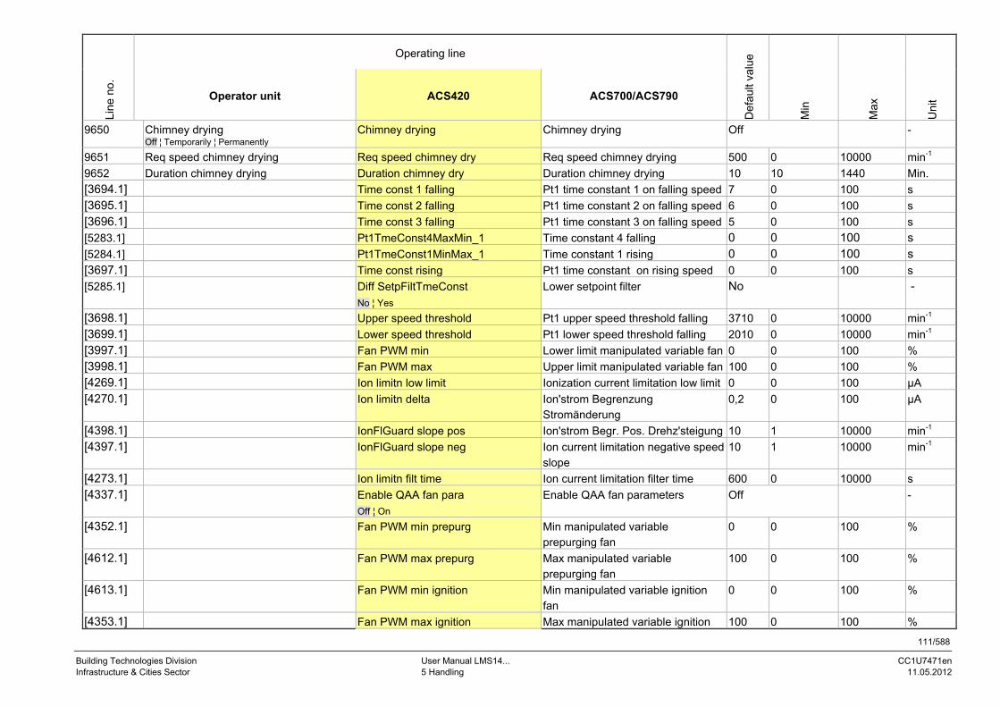
111/588
Building Technologies Division User Manual LMS14... CC1U7471en Infrastructure & Cities Sector 5 Handling 11.05.2012
Operating line
Line
no.
Operator unit ACS420 ACS700/ACS790
Def
ault
valu
e
Min
Max
Uni
t
9650 Chimney drying Off ¦ Temporarily ¦ Permanently
Chimney drying Chimney drying Off -
9651 Req speed chimney drying Req speed chimney dry Req speed chimney drying 500 0 10000 min-1
9652 Duration chimney drying Duration chimney dry Duration chimney drying 10 10 1440 Min.
[3694.1] Time const 1 falling Pt1 time constant 1 on falling speed 7 0 100 s
[3695.1] Time const 2 falling Pt1 time constant 2 on falling speed 6 0 100 s
[3696.1] Time const 3 falling Pt1 time constant 3 on falling speed 5 0 100 s
[5283.1] Pt1TmeConst4MaxMin_1 Time constant 4 falling 0 0 100 s
[5284.1] Pt1TmeConst1MinMax_1 Time constant 1 rising 0 0 100 s [3697.1] Time const rising Pt1 time constant on rising speed 0 0 100 s
[5285.1] Diff SetpFiltTmeConst
No ¦ Yes
Lower setpoint filter No -
[3698.1] Upper speed threshold Pt1 upper speed threshold falling 3710 0 10000 min-1
[3699.1] Lower speed threshold Pt1 lower speed threshold falling 2010 0 10000 min-1
[3997.1] Fan PWM min Lower limit manipulated variable fan 0 0 100 %
[3998.1] Fan PWM max Upper limit manipulated variable fan 100 0 100 %
[4269.1] Ion limitn low limit Ionization current limitation low limit 0 0 100 µA
[4270.1] Ion limitn delta Ion'strom Begrenzung Stromänderung
0,2 0 100 µA
[4398.1] IonFlGuard slope pos Ion'strom Begr. Pos. Drehz'steigung 10 1 10000 min-1
[4397.1] IonFlGuard slope neg Ion current limitation negative speed slope
10 1 10000 min-1
[4273.1] Ion limitn filt time Ion current limitation filter time 600 0 10000 s
[4337.1] Enable QAA fan para
Off ¦ On
Enable QAA fan parameters Off -
[4352.1] Fan PWM min prepurg Min manipulated variable prepurging fan
0 0 100 %
[4612.1] Fan PWM max prepurg Max manipulated variable prepurging fan
100 0 100 %
[4613.1] Fan PWM min ignition Min manipulated variable ignition fan
0 0 100 %
[4353.1] Fan PWM max ignition Max manipulated variable ignition 100 0 100 %

112/588
Building Technologies Division User Manual LMS14... CC1U7471en Infrastructure & Cities Sector 5 Handling 11.05.2012
Operating line
Line
no.
Operator unit ACS420 ACS700/ACS790
Def
ault
valu
e
Min
Max
Uni
t
fan
[4354.1] Fan PWM min low-fire Min manipulated variable low-fire fan
0 0 100 %
[4355.1] Fan PWM max high-fire Max manipulated variable high-fire fan
100 0 100 %
[4366.1] Max speed prepurging Max speed prepurging 10000 200 10000 min-1
[4378.1] Config reaction LT/SLT
Start prevention ¦ Lockout position
Configure reaction mech LT/SLT Start prevention -
[3633.1] RepCounter flame TSA Repetition counter establishment of flame
4 1 25 -
[3632.1] RepCounter flame Repetition counter loss of flame in operation
25 1 25 -
[6086.1] Max StartAttempts Opt 1
Inactive | Active
Maximum start attempts option 1 Inactive
[4495.1] Remote reset SLT ParRemoteUnlockEnableSLT No -
[4496.1] Remote reset air ParRemoteUnlockEnableAir No -
[4497.1] Rem res extran light ParRemoteUnlockEnableExtranLight
No -
[4498.1] Remote reset flame ParRemoteUnlockEnableFlame No -
[4777.1]*) Prepu outp OEM limit Prepurge output OEM limit 0 0 2000 kW [4778.1] *) Ign outp OEM limit Ignition output OEM limit 0 0 2000 kW [4779.1] *) LF outp OEM limit Low-fire output OEM limit 0 0 2000 kW [4780.1] *) HF outp OEM limit High-fire output OEM limit 0 0 2000 kW [4781.1] *) Max output OEM limit Max output OEM limit 0 0 2000 kW [4782.1] *) Min output OEM limit Min output OEM limit 0 0 2000 kW Production
[5000.1] SW version number SW version number - 0 65535
[4763.1] ParaSettingHistory History of last 4 parameterizations - 0 255
[4762.1] OnlineDD group number OnlineDD group number - 0 65535
[4689.1] CustomerNo_ParaSet Customer number from parameter set
- - - -
[3891.1] Mains frequency Mains frequency - 0 65535

113/588
Building Technologies Division User Manual LMS14... CC1U7471en Infrastructure & Cities Sector 5 Handling 11.05.2012
Operating line
Line
no.
Operator unit ACS420 ACS700/ACS790
Def
ault
valu
e
Min
Max
Uni
t
[3907.1] Mains voltage Mains voltage - 0 65535 V
Note! *) These parameters appear only when enabling the output parameters (factory setting). Refer to chapter Fan parameters settable as load values via QAA75.../AVS37...
Warning! Under the most unfavorable conditions, it may take up to 40 seconds for signal H2 from the extension modules via BSB to become refreshed in the LMS14… This can lead to functional limitations with the DHW flow switch and to crucial situations in connection with limit functions! For such functions, use inputs H1 and inputs H3…H7.

114/588
Building Technologies Division User Manual LMS14… CC1U7471en Infrastructure & Cities Sector 6 The settings in detail 11.05.2012
6 The settings in detail 6.1 Time of day and date The controller has a yearly clock with time of day, weekday and date. To ensure the controller will operate as required, both time of day and date must be correctly set.
6.1.1 Summer-/wintertime changeover The dates set for the changeover from wintertime to summertime, and vice versa, ensure that on the first Sunday after the set date the time of day will change from 02:00 (wintertime) to 03:00 (summertime), and from 03:00 (summertime) to 02:00 (wintertime).
Line no. Operating line
1 Hours/minutes
Line no. Operating line
2 Day/month
Line no. Operating line
3 Year
Line no. Operating line
5 Start of summertime
Line no. Operating line
6 End of summertime
Hours/minutes
Day/month
Year
Start of summertime
End of summertime
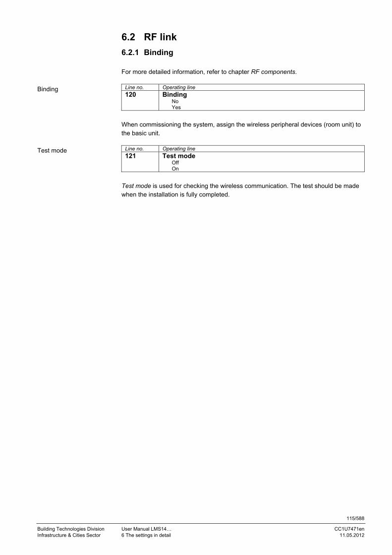
115/588
Building Technologies Division User Manual LMS14… CC1U7471en Infrastructure & Cities Sector 6 The settings in detail 11.05.2012
6.2 RF link
6.2.1 Binding For more detailed information, refer to chapter RF components.
Line no. Operating line
120 Binding No Yes
When commissioning the system, assign the wireless peripheral devices (room unit) to the basic unit.
Line no. Operating line
121 Test mode Off On
Test mode is used for checking the wireless communication. The test should be made when the installation is fully completed.
Binding
Test mode

116/588
Building Technologies Division User Manual LMS14… CC1U7471en Infrastructure & Cities Sector 6 The settings in detail 11.05.2012
6.2.2 List of wireless devices
Line no. Operating line
130 Room unit 1 Missing In operation No recept'n Change batt
131 Room unit 2 Missing In operation No recept'n Change batt
132 Room unit 3 Missing In operation No recept'n Change batt
Line no. Operating line
133 Outside sensor Missing In operation No recept'n Change batt
Line no. Operating line
134 Repeater Missing In operation No recept'n Change batt
Line no. Operating line
135 Operator unit 1 Missing In operation No recept'n Change batt
136 Operator unit 2 Missing In operation No recept'n Change batt
137 Operator unit 3 Missing In operation No recept'n Change batt
Line no. Operating line
138 Service unit Missing In operation No recept'n Change batt
Line no. Operating line
140 Delete all devices No Yes
The RF link to all devices is canceled. If wireless communication is required again, set up a new binding.
Room unit 1/2/3
Outside sensor
Repeater
Operator unit 1/2/3
Service unit
Delete all devices
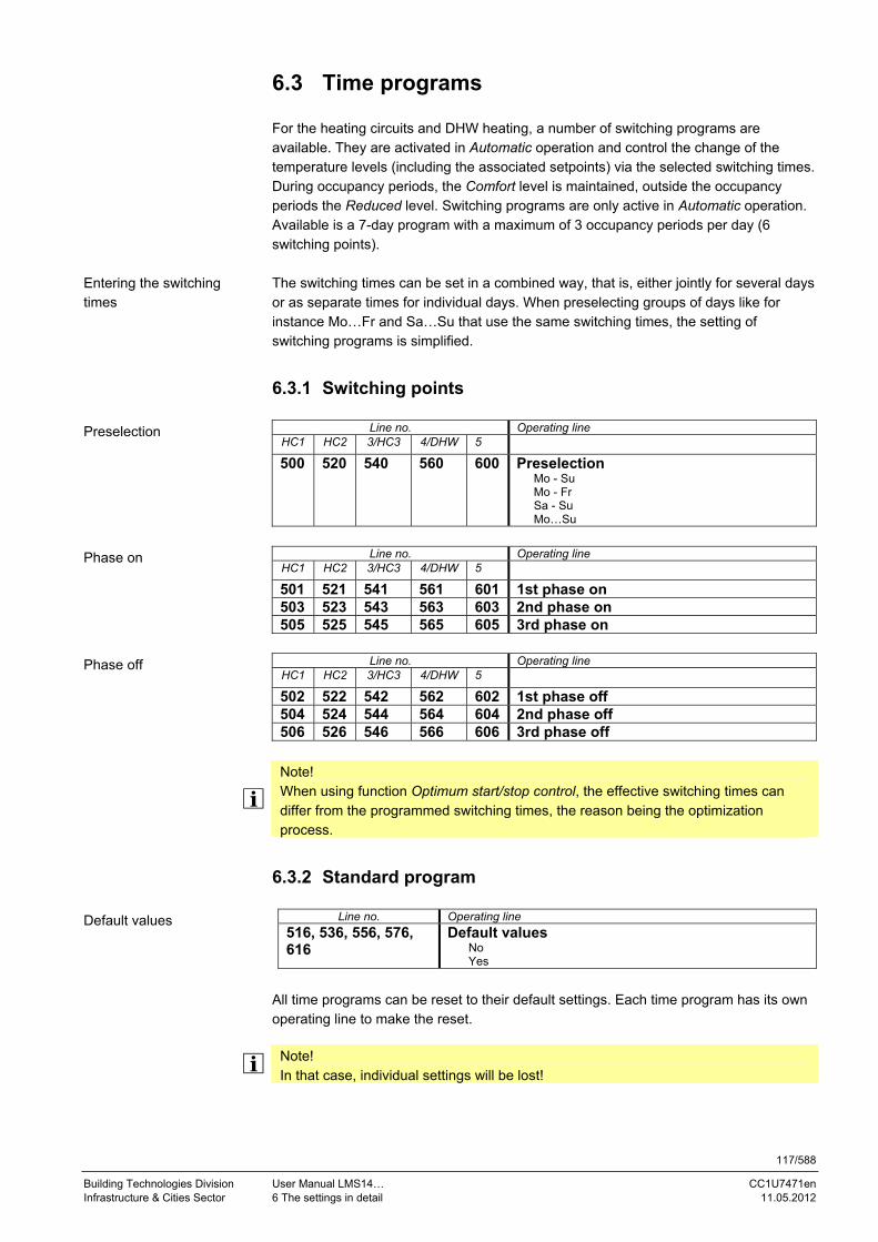
117/588
Building Technologies Division User Manual LMS14… CC1U7471en Infrastructure & Cities Sector 6 The settings in detail 11.05.2012
6.3 Time programs For the heating circuits and DHW heating, a number of switching programs are available. They are activated in Automatic operation and control the change of the temperature levels (including the associated setpoints) via the selected switching times. During occupancy periods, the Comfort level is maintained, outside the occupancy periods the Reduced level. Switching programs are only active in Automatic operation. Available is a 7-day program with a maximum of 3 occupancy periods per day (6 switching points). The switching times can be set in a combined way, that is, either jointly for several days or as separate times for individual days. When preselecting groups of days like for instance Mo…Fr and Sa…Su that use the same switching times, the setting of switching programs is simplified.
6.3.1 Switching points
Line no. Operating line HC1 HC2 3/HC3 4/DHW 5 500 520 540 560 600 Preselection
Mo - Su Mo - Fr Sa - Su Mo…Su
Line no. Operating line
HC1 HC2 3/HC3 4/DHW 5 501 521 541 561 601 1st phase on 503 523 543 563 603 2nd phase on 505 525 545 565 605 3rd phase on
Line no. Operating line
HC1 HC2 3/HC3 4/DHW 5 502 522 542 562 602 1st phase off 504 524 544 564 604 2nd phase off 506 526 546 566 606 3rd phase off
Note! When using function Optimum start/stop control, the effective switching times can differ from the programmed switching times, the reason being the optimization process.
6.3.2 Standard program
Line no. Operating line
516, 536, 556, 576, 616
Default values No Yes
All time programs can be reset to their default settings. Each time program has its own operating line to make the reset.
Note! In that case, individual settings will be lost!
Entering the switching times
Preselection
Phase on
Phase off
Default values

118/588
Building Technologies Division User Manual LMS14… CC1U7471en Infrastructure & Cities Sector 6 The settings in detail 11.05.2012
6.4 Holidays
Line no. Operating line
HC1 HC2 HC3
641 651 661 Preselection Period 1
Period 2
Period 3
Period 4
Period 5
Period 6
Period 7
Period 8
Line no. Operating line
HC1 HC2 HC1
642 652 662 Start
Line no. Operating line
HC1 HC2 HC1
643 653 663 End
Line no. Operating line
HC1 HC2 HC1
648 658 668 Operating level Frost protection
Reduced
The holiday program enables holiday periods to be preprogrammed for a full calendar year. When a holiday period is active, the operating level switches to Reduced or Frost protection (selectable).
Note! The holiday program can only be used in Automatic operation.
Holiday periods are only active in Automatic operation. In the other operating modes, they are started and run in the background to become active whenever Automatic operation is selected. When a holiday period has elapsed, the controller automatically deletes it. The same holiday period the following year would have to be reprogrammed. A holiday period starts at 0:00 of the first day and ends/is deleted at 24:00 of the last day of the holiday period. An active holiday period is indicated by the suitcase symbol. The heating circuit’s operating mode does not change. It is possible to enter a holiday period with the date of the first and last day of the period (dd.mm). The operating level that shall apply during active holiday periods can be selected (Reduced or Protection). The impact of a currently active holiday period can only be canceled by switching to non-automatic operation or by deleting the programmed holiday period.
Preselection
Start
End
Operating level

119/588
Building Technologies Division User Manual LMS14… CC1U7471en Infrastructure & Cities Sector 6 The settings in detail 11.05.2012
Note! The holiday program has an impact on DHW heating. If, for example, all heating circuits are on holiday, DHW heating assigned to these heating circuits will be switched off.
Note! The LMS14… offers 8 holiday periods per year:
Setting several holiday periods: Use parameter Preselection (641/651/661) to select the required holiday period (1 - 8). Then, enter to dates required for the corresponding holiday period using Start (642/652/662) and End (643/653/663).
Note! The selected operating level is the same for all holiday periods.

120/588
Building Technologies Division User Manual LMS14… CC1U7471en Infrastructure & Cities Sector 6 The settings in detail 11.05.2012
6.5 Heating circuits For the heating circuits, a number of functions are available which can be individually set for each heating circuit. Every heating circuit can be a virtual circuit, pump circuit or mixing circuit. The Mixing function is available only when an external extension module is used.
Note! Heating circuits 1, 2 and 3 can be switched on/off via parameter if, for example, a request for heat shall only be generated via external consumer group 1/2/3.
If, with the mixing circuit, the flow sensor is not connected, it becomes a pump circuit with regard to functions.
6.5.1 Operating mode
Line no. Operating line HC1 HC2 HC3
700 1000 1300 Operating mode Protection Automatic Reduced Comfort
The operating modes of the heating circuits are selected directly with the operating mode button. This setting is used to switch between different operating modes. Functionality corresponds to the operating mode selection via the operating mode button. For details, refer to section Operation.
Note! The operating mode can also be changed via input H (refer to chapter Operating mode changeover via input H).
Protection Continuous operation (24 hours) at the Frost protection level. Switching program, presence button, holiday program, optimum start/stop control and ECO program have no impact.
Note! When using a room thermostat, it normally prevents the room temperature from falling and must be set to a level that ensures frost protection for the room (also refer to chapters Compensation variant, Room model, and Frost protection for the room). In the case of compensation variants RT-RR and RT-WR, frost protection for the room according to chapter Frost protection for the room can become active because a room sensor is installed and as a result of the acquired room temperature, even if the room thermostat signals Warm.
Automatic Automatic operation at the Comfort, Reduced or Frost protection level in accordance with the switching program, the presence button, the holiday program, optimum start/stop control and the ECO function.
Operating mode

121/588
Building Technologies Division User Manual LMS14… CC1U7471en Infrastructure & Cities Sector 6 The settings in detail 11.05.2012
Reduced Continuous operation (24 hours) at the Reduced level. Switching program, presence button, holiday program, optimum start/stop control and ECO program have no impact. The protective functions remain active. Comfort Continuous operation (24 hours) at the Comfort level. Switching program, presence button, holiday program, optimum start/stop control and ECO program have no impact. The protective functions remain active.

122/588
Building Technologies Division User Manual LMS14… CC1U7471en Infrastructure & Cities Sector 6 The settings in detail 11.05.2012
6.5.2 Compensation variants The compensation variant (CV) determines the variable (outside temperature or room temperature setpoint) according to which the flow temperature of the heating circuits shall be controlled. The compensation variant is generated automatically based on the existing temperature values of outside temperature (OT), room temperature (TR), parameterization of room thermostat setpoint and the room thermostat inputs. Parameter Room influence (750/1050/1350) impacts the compensation behavior if there is no room thermostat and if both temperature values are available. The following compensation variants are available: Weather compensation alone (WW) Control is performed via the heating curve, based solely on the outside temperature. Room temperature control (RR): Control is performed based solely on the room temperature. Weather compensation with room influence (WR): Control is performed via the heating curve and the room temperature, based on the outside temperature. Room thermostat control with setpoint (RT-S) Control is performed only when the room thermostat’s state is Cold, using a fixed setpoint. Room thermostat control with weather compensation alone (RT-WW) Control is performed only when the room thermostat’s state is Cold, based on the outside temperature and the heating curve. Room thermostat control with room control (RT-RR)
Note! Control is performed only when the room thermostat’s state is Cold, based on the room temperature. This setting may result from the use of a room thermostat in connection with a room unit with built-in sensor, but does not make much sense from a practical point of view.
Room thermostat control and weather compensation with room influence (RT-WR)
Note! Control is performed only when the room thermostat’s state is Cold, based on the outside temperature, the heating curve and the room temperature. This setting may result from the use of a room thermostat in connection with a room unit with built-in sensor, but does not make much sense from a practical point of view.
Generation of compensation variant
Compensation variants

123/588
Building Technologies Division User Manual LMS14… CC1U7471en Infrastructure & Cities Sector 6 The settings in detail 11.05.2012
Room thermostat
input
Room thermostat
setpoint
Room temperature Outside
temperature
Room influence Compensation
variant
Compensati
on
variant error
Not available Not available Not available WW Outside
temperature
not available
Not available Not available Installed WW No
Not available Installed Not available Room control No
Not available Installed Installed --- (Off) WW No
Not available Installed Installed 1...99% WR No
Not available Installed Installed 100% Room control No
Installed Valid ▲ ▲ RT-S No
Installed --- (Off) Not available Not available RT-WW Outside
temperature
not available
Installed --- (Off) Not available Installed RT-WW No
Installed --- (Off) Installed Not available RT-RR No
Installed --- (Off) Installed Installed --- (Off) RT-WW No
Installed --- (Off) Installed Installed 1...99% RT-WR No
Installed --- (Off) Installed Installed 100% RT-RR No
= setting with no impact ▲ = setting has no impact on the compensation variant; ECO functions (summer/winter heating limit/ 24-hour heating limit/room temperature limitation) remain active depending on the availability of a sensor (room sensor/outside sensor)
Key
WW Weather compensation alone
WR Weather compensation with room influence
RT-S Room thermostat control with setpoint
RT-WW Room thermostat control with weather compensation alone
RT Room thermostat control
RT-WR Room thermostat control and weather compensation with room influence
RT-RR Room thermostat control with room control
RR Room control
Room thermostat input: An input Hx as a room thermostat is assigned to the
heating circuit Room thermostat setpoint: Flow temp setpoint room stat (742/1042/1342) Room influence: 750/1050/1350
Note! If neither of the temperature values (room temperature and outside temperature) is available, weather compensation (WW) is used with the substitution value 0 °C for the outside temperature. In that case, an error message is delivered. With room control, frost protection for the plant must be switched off if there is no outside sensor.
Generation of the compensation variant is possible for each heating circuit and can be set accordingly.

124/588
Building Technologies Division User Manual LMS14… CC1U7471en Infrastructure & Cities Sector 6 The settings in detail 11.05.2012
6.5.3 Occupancy button (presence button) If, as a result of the time switch settings, current comfort needs are not satisfied, the operating level can be manually changed via the operator unit by pressing the occupancy button (presence button). The presence button is only active in Automatic operation.
SP
PT
71010101310
OR
PT PT PT7471d15/0910
Figure 15: Presence button
Key
Line no. Meaning HC1 HC2 HC3
710 1010 1310 TRK Room temperature Comfort setpoint SP Switching program OR Override PT Pressing the presence button
The effect of pressing the presence button continues until the next switching point is reached. When the button is pressed again, the state is canceled.
6.5.4 Operating level Based on the different impacts (operating mode, input Hx, holiday program, time switch, presence button), the operating level is generated which, however, does not yet include the influence of optimum start/stop control.
Operating mode of heating circuit
State of time switch
State of presence
button
State of holiday
program
Operating level HC (before
optimization)
Automatic Active Reduced/Frost *Automatic Reduced phase No override Inactive Reduced Automatic Reduced phase Override Inactive Comfort Automatic Comfort phase No override Inactive Comfort Automatic Comfort phase Override Inactive Reduced Comfort Comfort Reduced Reduced Protection Frost
= can be any
* Selectable whether the holiday program shall switch to Reduced or Frost
Note! The operating level can also be changed via input H (refer to chapter Operating level changeover via input H).
Generating the operating level (BN)

125/588
Building Technologies Division User Manual LMS14… CC1U7471en Infrastructure & Cities Sector 6 The settings in detail 11.05.2012
6.5.5 Setpoints
Line no. Operating line HC1 HC2 HC3
710 1010 1310 Comfort setpoint
Line no. Operating line HC1 HC2 HC3
712 1012 1312 Reduced setpoint
Line no. Operating line HC1 HC2 HC3
714 1014 1314 Frost protection setpoint In Protection mode, the room temperature is prevented from falling below a certain level. This means that the Frost Protection setpoint of the room temperature is maintained.
Line no. Operating line HC1 HC2 HC3
716 1016 1316 Comfort setpoint max The room temperature can be shifted according to different setpoints. These setpoints become active depending on the selected operating mode, thus producing different temperature levels in the rooms. The ranges of adjustable setpoints result from interdependencies, as this is shown in the following diagram:
0 2 4 6 8 10 12 14 16 18 20 22 24 26 °C
7471z83/0910
BZ 710BZ 1010BZ 1310
BZ 712 / BZ 1012 / BZ 1312
BZ 714 / Bz1014 / Bz1314
BZ 716BZ 1016BZ 1316
Figure 16: Setpoints
Key
Line no. Meaning HC1 HC2 HC3
710 1010 1310 TRK Room temperature Comfort setpoint 712 1012 1312 TRR Room temperature Reduced setpoint 714 1014 1314 TRF Frost protection setpoint 716 1016 1316 TRKmax Maximum room temperature Comfort setpoint
Comfort setpoint
Reduced setpoint
Frost protection setpoint
Comfort setpoint max
Room temperature

126/588
Building Technologies Division User Manual LMS14… CC1U7471en Infrastructure & Cities Sector 6 The settings in detail 11.05.2012
6.5.6 Heating curve The heating curve generates the flow temperature setpoint, which is used to maintain a certain flow temperature level depending on the prevailing weather conditions. The heating curve can be adjusted in different ways, thus matching the heat output and the room temperature to individual needs.
Line no. Operating line HC1 HC2 HC3
720 1020 1320 Heating curve slope When the heating curve slope is raised, the flow temperature increases as the outside temperature drops. Or, in other words, if the room temperature is not correct at low outside temperatures but correct at higher outside temperatures, the heating curve slope must be readjusted. Increasing the slope: Raises the flow temperature, especially when the outside
temperature is low.
Decreasing the slope: Lowers the flow temperature, especially when the outside temperature is low.
Note! The set heating curve is based on a room temperature setpoint of 20 °C. If this setpoint is changed, the heating curve adapts automatically to the new value.
Figure 17: Heating curve – heating curve slope
Heating curve slope

127/588
Building Technologies Division User Manual LMS14… CC1U7471en Infrastructure & Cities Sector 6 The settings in detail 11.05.2012
The resulting flow temperature can be calculated as follows: TV = TR + [ 2 + (TR - TAgem) - 0.005 * (TR - TAgem)2 ] * s The impact of compensation variant Weather compensation with room influence on the flow temperature setpoint is calculated as follows: TV = TRw * (1 + s)
Key Line no. Meaning
TV Resulting flow temperature adaption
TRw Room temperature setpoint readjustment (due to room influence)
TV Flow temperature setpoint heating circuit
TR Room temperature setpoint – heat gains + room influence
TAgem Composite outside temperature
s Heating curve slope
Line no. Operating line
HC1 HC2 HC3
721 1021 1321 Heating curve displacement Parallel displacement of the heating curve is used to change the flow temperature evenly across the entire outside temperature range or, in other words, if the room temperature is always too high or too low, a readjustment must be made via parallel displacement.
20 10 0 -10 -20 -30
90
80
70
60
50
40
30
°C
°C
100
0
1010
0
30
TRw
8700
TV
7471d48/0910
Figure 18: Heating curve – heating curve displacement
Key
Line no. Meaning
8700 TA Outside temperature
TRw Room temperature setpoint
TV Flow temperature
Calculation
Heating curve displacement

128/588
Building Technologies Division User Manual LMS14… CC1U7471en Infrastructure & Cities Sector 6 The settings in detail 11.05.2012
Line no. Operating line
HC1 HC2 HC3
726 1026 1326 Heating curve adaption Off On
Adaption of the heating curve is used by the controller to automatically adapt the heating curve to the prevailing weather conditions. In that case, a readjustment of heating curve slope and parallel displacement is not required. It can only be switched on or off.
Note! To provide this function, following must be observed: A room sensor must be connected The Room influence setting must be selected between 1 and 99 No thermostatic radiator valves should be used in the reference room, where the
room sensor is located (if installed, such valves must be fully opened and locked in that position)
Off Function is deactivated. On Function is activated. The function is activated via parameter, provided a room sensor is used and the compensation variant WR (Weather compensation with room influence). If the required flow temperature is exceeded or is not reached for more than 2 hours, no adaption is made for that day. With pump heating circuits, the boiler temperature is used in place of the flow temperature. Heating curve adaption readjusts the heating curve’s slope and the parallel displacement (heat gains). In Comfort mode (nominal operating level), the function integrates the room temperature control deviation and readjusts at midnight the parameters for calculating the heating curve, depending on the attenuated outside temperature and the learning sensitivity. During boost heating, the deviation of room temperature control is not taken into consideration. After each learning step, the learning sensitivity is reduced step by step. If the heating curve’s slope or parallel displacement (heat gains) is changed, the sensitivity is automatically set to the maximum. A certain minimum sensitivity is always maintained. If the attenuated outside temperature is below 4 °C, the heating curve slope is readjusted through the learning process. If the attenuated outside temperature lies between 4 °C and 12 °C, heating curve slope and parallel displacement are readjusted through learning. If the attenuated outside temperature exceeds 12 °C, the learning process is stopped. These basic values apply to a Comfort setpoint of 20 °C, heat gains of 0 K and a heating curve displacement of 0 K.
Heating curve adaption

129/588
Building Technologies Division User Manual LMS14… CC1U7471en Infrastructure & Cities Sector 6 The settings in detail 11.05.2012
6.5.7 ECO function
Line no. Operating line
HC1 HC2 HC3
730 1030 1330 Summer/winter heating limit The summer/winter heating limit is used to switch the heating on and off in the course of the year, depending on the outside temperature. In Automatic operation, switching on/off takes place automatically, so there is no need for the user to do this manually. The respective periods of time are shortened or extended by changing the setting. The Summer/winter changeover function switches the heating off when the attenuated outside temperature exceeds the adjusted changeover temperature. The heating system is switched on again when the attenuated outside temperature drops 1 K below the adjusted value. The required changeover temperature can be parameterized. The function can be activated/deactivated. Increase: Winter operation will start earlier.
Summer operation will start later.
Decrease: Winter operation will start later. Summer operation will start earlier.
Note!
The function is not active in Comfort mode The display shows ECO To give consideration to the building's thermal dynamics, the outside
temperature is attenuated Example:
°C
730 / 1030 / 1330
730 / 1030 / 1330 -1 °C
Figure 19: ECO function – summer/winter heating limit
Key Line no. Meaning
HC1 HC2 HC3
730 1030 1330 SWHG Summer/winter heating limit
8703 TAged Attenuated outside temperature
t Days
T Temperature
Summer/winter heating limit

130/588
Building Technologies Division User Manual LMS14… CC1U7471en Infrastructure & Cities Sector 6 The settings in detail 11.05.2012
Line no. Operating line
HC1 HC2 HC3
732 1032 1332 24-hour heating limit The 24-hour heating limit is used to switch the heating on and off in the course of the day, depending on the outside temperature. This function is used primarily during spring and autumn to respond to short-term temperature variations. The 24-hour heating limit function switches the heating system off when the current outside temperature or the composite outside temperature rises to a level of one adjusted differential below the current operating level. The heating is switched on again when the current outside temperature and the composite outside temperature drop 1 K below the adjusted differential.
Note! In Comfort mode, the function is always deactivated.
The required ECO temperature differential can be parameterized. The function can be activated/deactivated.
T
t
01
8700
8704
H
1°C
73210321332
TRw
7471d16/0910 Figure 20: Eco function – 24-hour heating limit
Key Line no. Meaning
HC1 HC2 HC3
8700 TA Outside temperature
8704 TAgem Composite outside temperature
732 1032 1332 THG 24-hour heating limit
H Heating (1 = On, 0 = Off)
t Time
T Temperature
TRw Room temperature setpoint
Example:
Operating line E.g.
Room temperature setpoint 22 °C24-hour heating limit (THG) -3 °CChangeover temperature (room temperature setpoint – setpoint of 24-hour heating limit), heating Off
= 19 °C
Switching differential (fixed) -1 °C
Changeover temperature, heating On = 18 °C
24-hour heating limit

131/588
Building Technologies Division User Manual LMS14… CC1U7471en Infrastructure & Cities Sector 6 The settings in detail 11.05.2012
The respective heating period is shortened or extended by changing the setting. Increase: Heating mode will start earlier.
Changeover to ECO later.
Decrease: Heating mode will start later. Changeover to ECO earlier.
Note! The function is not active in operating mode Continuously Comfort temperature
The display shows ECO To give consideration to the building's thermal dynamics, the outside
temperature is attenuated
Line no. Operating line
HC1 HC2 HC3
733 1033 1333 Ext’n 24-hour heating limit No
Yes
The 24-hour heating limit is extended by giving consideration to the composite outside temperature when the heating is switched on. Alternatively, the heating can be switched on again solely depending on the current outside temperature. No The 24-hour heating limit takes effect solely depending on the current outside temperature. Yes The 24-hour heating limit takes effect as described under 24-hour heating limit, depending on both the current and the composite outside temperature.
Ext’n 24-hour heating limit

132/588
Building Technologies Division User Manual LMS14… CC1U7471en Infrastructure & Cities Sector 6 The settings in detail 11.05.2012
6.5.8 Flow temperature setpoint limits
Line no. Operating line HC1 HC2 HC3
740 1040 1340 Flow temp setpoint min 741 1041 1341 Flow temp setpoint max Using this limitation, a temperature range for the flow temperature setpoint can be defined. If the flow temperature setpoint called for by the heating circuit reaches the relevant limit and the request for heat increases or decreases, the flow temperature setpoint is maintained at the maximum or minimum limit.
0 10 20 30 40 50 60 70 80 90 100
TV
Max.
Min.
Act.
°C
8744 / 8774 / 8803
740 / 1040 / 1340
74110411341
74
71
z85
e/0
311
Figure 21: Flow temperature setpoint limits
Key
Line no. Meaning HC1 HC2 HC3
740 1040 1340 TVmin Minimum flow temperature setpoint 741 1041 1341 TVmax Maximum flow temperature setpoint 8744 8774 8803 TVw Flow temperature setpoint 1/2/3
The calculated flow temperature setpoint is limited according to the setting made. The limitation is active in all operating modes. Even forced signals cannot push the flow temperature setpoint above that level.
Warning! Maximum limitation is not a safety function. If the flow temperature exceeds this limit, the heating circuit pump will not be deactivated. The flow temperature setpoint is limited according to the setting made. This also applies to heat requests made to the heat sources.
Flow temp setpoint min/max
Flow temp setpoint max
Flow temp setpoint min

133/588
Building Technologies Division User Manual LMS14… CC1U7471en Infrastructure & Cities Sector 6 The settings in detail 11.05.2012
6.5.9 Room thermostat On applications with room thermostat, the heating is switched on only when the room thermostat calls for heat. When the thermostat is in the Cold state, a fixed or weather-dependent flow temperature setpoint can be selected.
Line no. Operating line
HC1 HC2 HC3
742 1042 1342 Flow temp setpoint room stat The differentiation is made via parameter Flow temp setpoint room stat: When a setting is made, the flow temperature setpoint corresponds to the fixed
value, which can be readjusted via the room thermostat’s adaption function When no setting is made (---), the flow temperature setpoint is calculated
according to the heating curve. This offers the advantage that – as usual – the output of the heating system can be adjusted via the heating curve slope and the room temperature setpoint. In that case, the room thermostat’s Adaption function acts on the heating curve. If no outside sensor is connected, the value of the heating curve at 0 °C (backup value) is used, and an error message (Outside sensor missing) is delivered
Functions with room thermostat
The following table gives an overview of the room functions and their modes of operation when using a room thermostat:
Function Description
Automatic summer/winter changeover
As parameterized; function is not available without outside sensor
24-hour heating limit As parameterized; function is not available without outside sensor
Boost heating As parameterized; ended when room thermostat switches to the Warm state
Quick setback Flow temperature setpoint as parameterized: Function is not available. Outside the Comfort phases, the heating is Off Flow temperature setpoint according to the heating curve: - With room sensor: As parameterized and according to the current room temperature if room influence is active - Without room sensor and with outside sensor: As parameterized and according to the room model Without outside sensor and without room sensor: - ParQuickSetback = off no quick setback - ParQuickSetback = reduced heating continuously on - ParQuickSetback = frost heating continuously on
Optimum start/stop control As parameterized; function is not available without outside sensor
Room influence As parameterized and according to the current room temperature, if room influence is active
Room limitation As parameterized; function is not available without room sensor
Adaption The room thermostat’s Adaption function can be specifically parameterized. For that purpose, the required cycling ratio of the room thermostat must be parameterized Flow temperature setpoint as parameterized: adaption of setpoint Flow temperature setpoint according to the heating curve: adaption of heating curve
Flow temp setpoint room stat

134/588
Building Technologies Division User Manual LMS14… CC1U7471en Infrastructure & Cities Sector 6 The settings in detail 11.05.2012
Flow temperature setpoint based on a fixed value
If the flow temperature setpoint is predefined via parameterization, the parameterized setpoint for the Comfort phases is only maintained when the room thermostat is in the Cold state. Outside the Comfort phases, the heating is also Off when the room thermostat is in the Cold state. If the room thermostat does not call for heat, the heating remains Off. Boost heating function: With functions Boost heating with room thermostat und Setpoint based on a fixed value, the flow temperature boost is calculated as a percentage and added to the parameterized setpoint. Boost heating remains active until the room thermostat switches to the Warm state. The function can be deactivated. Note! When an outside sensor is connected, frost protection for the plant can be activated. When frost protection for the plant has responded (at low outside temperatures), the pump is also activated outside the Comfort phases. Heat requests do not become active. If, in addition, a room sensor is used, room temperature limitation can also be activated. Function Room influence is not active. The fixed flow temperature setpoint can be deactivated (---) (if a fixed value is not parameterized, the flow temperature is calculated based on the heating curve). If no outside sensor is connected, the backup outside temperature of 0 º C is used (refer to chapters Flow temperature setpoint according to the heating curve and Adaption with flow temperature setpoint according to the heating curve.)

135/588
Building Technologies Division User Manual LMS14… CC1U7471en Infrastructure & Cities Sector 6 The settings in detail 11.05.2012
Flow temperature setpoint in case of fixed value with adaption
If the flow temperature setpoint is predefined via parameterization, the value can be adapted depending on the demand for heat. This function ensures that the heat request sent to the heat source during the entire heating season does not always represent the high setpoint required for the very cold season. The function requires no outside sensor. Adaption can be deactivated (---).
Line no. Operating line HK1 HK2 HK3
744 1044 1344 Swi-on ratio room stat Adaption of the setpoint is subdivided into 2 functions: Dynamic readjustment of flow temperature setpoint If the current flow temperature setpoint is too low, dynamic readjustment adapts the current demand for heat. To make the readjustment, the room thermostat’s current cold-warm time ratio is compared with the target value. If, during Comfort phases, the cold phase is too long, the setpoint is increased. If a cold-warm time ratio is not yet available when switching to Comfort, the setpoint is increased if the room thermostat remains in the Cold state for more than 2 hours. To prevent the flow temperature from rising too quickly in the case of very short warm phases, dynamic readjustment is activated after 30 minutes at the earliest. Midnight adaption for the next day Based on the demand for heat of the previous day, midnight adaption readjusts the amount of heat required for the next day. This adaption changes the parameterized flow temperature setpoint. The adapted value is stored and used should a power failure occur. For adaption, a cold-warm time ratio of the room thermostat is predefined as a target value (1…99%). If, during Comfort phases, the cold phase is too long, the setpoint is raised. If the cold phase is too short, the setpoint is lowered. Parameterized boost heating is taken into consideration when calculating the required readjustment. The setpoint is readjusted at midnight. If, at midnight, the room thermostat is in the Warm state, the setpoint readjustment is not made until the room thermostat switches to the Cold state.
Swi-on ratio room stat

136/588
Building Technologies Division User Manual LMS14… CC1U7471en Infrastructure & Cities Sector 6 The settings in detail 11.05.2012
Flow temperature setpoint according to the heating curve
In the case of a weather-compensated flow temperature setpoint (fixed value not parameterized), the setpoint is calculated based on the outside sensor and the heating curve. When the room thermostat is in the Cold state, the heating is switched on according to the current heating level, irrespective of operating mode. Functions Boost heating, Quick setback and Optimum start/stop control are taken into consideration. Without room sensor, the room model is used. Functions Room temperature limitation and Room influence can be provided only if a room sensor is connected.
Note! If an outside sensor is not connected, the heating curve is calculated based on the backup outside temperature of 0 °C.
Adaption with flow temperature setpoint according to the heating curve
If the flow temperature setpoint is calculated via the heating curve (no fixed value parameterized) and the room thermostat’s Adaption function is active, the heating curve’s slope and thus the flow temperature setpoint will be adapted. Adaption takes place at midnight (like with the normal heating curve adaption with room sensor). To ensure adaption, neither a room sensor nor an outside sensor is mandatory. Adaption at midnight Based on the demand for heat of the previous day, adaption of the heating curve readjusts the slope. The adapted slope is stored and used should a power failure occur. For adaption, a cold-warm time ratio of the room thermostat is predefined as a target value (1…99%). If, during Comfort phases, the cold phase is too long, the heating curve slope is increased. If the cold phase is too short, the heating curve slope is decreased. The duration of boost heating – if parameterized – is not taken into account for the cold-warm time ratio. Dynamic readjustment during the Comfort phases With the weather-compensated flow temperature setpoint, dynamic readjustment of the setpoint is not required. In that case, the heat request is continuously matched to varying conditions in accordance with the composite outside temperature. Adaption can be deactivated (---).
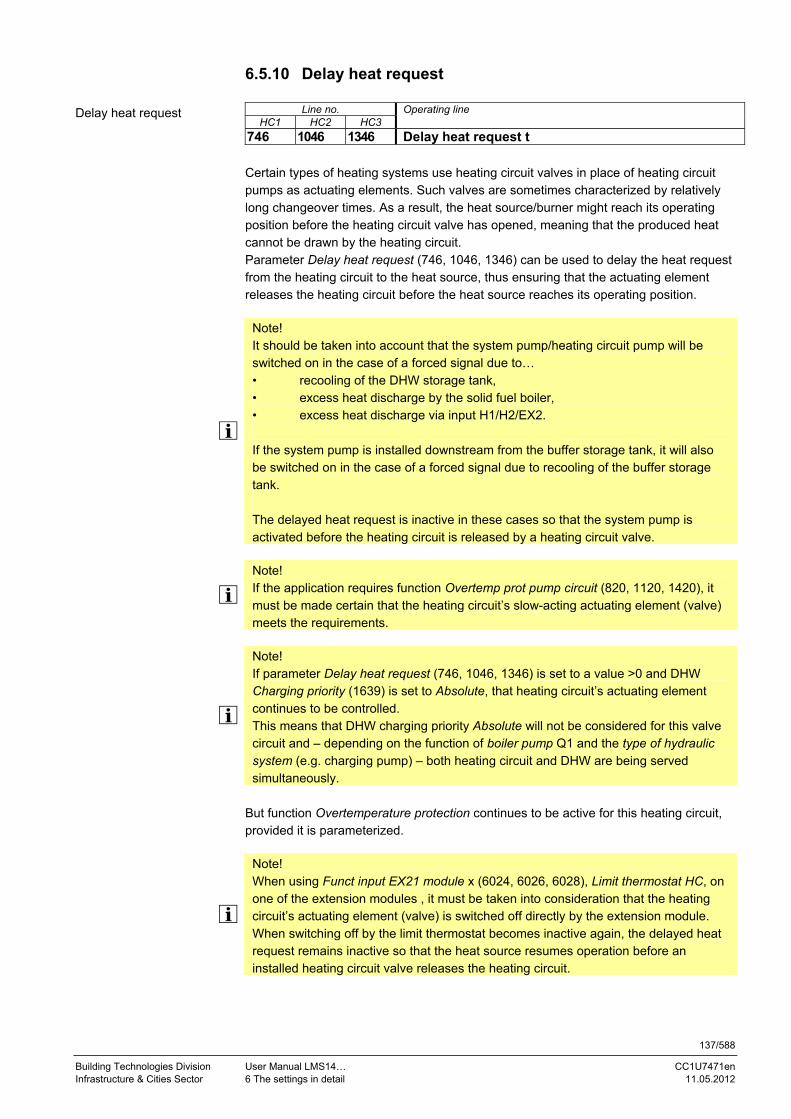
137/588
Building Technologies Division User Manual LMS14… CC1U7471en Infrastructure & Cities Sector 6 The settings in detail 11.05.2012
6.5.10 Delay heat request
Line no. Operating line HC1 HC2 HC3
746 1046 1346 Delay heat request t Certain types of heating systems use heating circuit valves in place of heating circuit pumps as actuating elements. Such valves are sometimes characterized by relatively long changeover times. As a result, the heat source/burner might reach its operating position before the heating circuit valve has opened, meaning that the produced heat cannot be drawn by the heating circuit. Parameter Delay heat request (746, 1046, 1346) can be used to delay the heat request from the heating circuit to the heat source, thus ensuring that the actuating element releases the heating circuit before the heat source reaches its operating position.
Note! It should be taken into account that the system pump/heating circuit pump will be switched on in the case of a forced signal due to… • recooling of the DHW storage tank, • excess heat discharge by the solid fuel boiler, • excess heat discharge via input H1/H2/EX2. If the system pump is installed downstream from the buffer storage tank, it will also be switched on in the case of a forced signal due to recooling of the buffer storage tank. The delayed heat request is inactive in these cases so that the system pump is activated before the heating circuit is released by a heating circuit valve.
Note! If the application requires function Overtemp prot pump circuit (820, 1120, 1420), it must be made certain that the heating circuit’s slow-acting actuating element (valve) meets the requirements.
Note! If parameter Delay heat request (746, 1046, 1346) is set to a value >0 and DHW Charging priority (1639) is set to Absolute, that heating circuit’s actuating element continues to be controlled. This means that DHW charging priority Absolute will not be considered for this valve circuit and – depending on the function of boiler pump Q1 and the type of hydraulic system (e.g. charging pump) – both heating circuit and DHW are being served simultaneously.
But function Overtemperature protection continues to be active for this heating circuit, provided it is parameterized.
Note! When using Funct input EX21 module x (6024, 6026, 6028), Limit thermostat HC, on one of the extension modules , it must be taken into consideration that the heating circuit’s actuating element (valve) is switched off directly by the extension module. When switching off by the limit thermostat becomes inactive again, the delayed heat request remains inactive so that the heat source resumes operation before an installed heating circuit valve releases the heating circuit.
Delay heat request

138/588
Building Technologies Division User Manual LMS14… CC1U7471en Infrastructure & Cities Sector 6 The settings in detail 11.05.2012
Note! For the instantaneous water heater, it can be selected whether the residual heat resulting from overrun shall be delivered to the instantaneous water heater or the heating circuits – Overrun via inst WH (5489). When supplied to the heating circuits, the delayed heat request becomes inactive. If the heat resulting from overrun is supplied to the heating circuit, the heating circuit’s actuating element must first be opened. If it is a valve, it might not be possible to supply the residual heat to that heating circuit.
Note! For the DHW diverting valve, parameter Pump off change div valve (5732) can be used to set the period of time the pump shall be off. Using Delay pump off (5733), a time shift between pump shutdown and control of the diverting valve can be parameterized. To ensure the heating circuit’s actuating element releases the heating circuit before the heat source is put into operation, parameter Delay heat request (746, 1046, 1346) must be increased by the amount of time the DHW diverting valve requires to change over.
Note! Parameter Delay heat request (746, 1046, 1346) is used to delay the heat request of the respective heating circuit to the heat source while the valve is already controlled. If the heat request results from a special function of the heat source (e.g. Chimney sweep function), the delay becomes inactive. In this case, parameter Delay heat request special op (2470) must be set as well.

139/588
Building Technologies Division User Manual LMS14… CC1U7471en Infrastructure & Cities Sector 6 The settings in detail 11.05.2012
6.5.11 Room model The room model calculates a fictive room temperature for rooms without room sensor. This allows boost heating, quick setback and optimum start/stop control to be implemented with no need for using a room sensor. The calculation takes into account the attenuated outside temperature and the heat up gradient for switching to a higher setpoint, plus the building’s time constant for switching to a lower setpoint.
TRw
8704
712 / 1012 / 1312
714 / 1014 / 1314
710 / 1010 / 1310
TRwAkt
8742 / 8772 / 8802
7471d17/0910 Figure 22: Room model
Key
Line no. Meaning
HC1 HC2 HC3
710 1010 1310 TRK Room temperature Comfort setpoint
712 1012 1312 TRR Room temperature Reduced setpoint
714 1014 1314 TRF Frost protection setpoint
8704 TAgem Composite outside temperature
8742 8772 8802 TRmod Room temperature model
TRwAkt Current room temperature setpoint
Note! The room model is always calculated. If the outside temperature is not available, the room model performs the calculation with a substitute value of 0 °C. Then, the Heating functions themselves decide on the source of the room temperature, based on the compensation variant and the state of the room sensor:
The model temperature is always used for the calculation if no room sensor is
available The model temperature is used for the calculation if weather compensation alone is
required The current temperature is used for the calculation if there is a room sensor and
room influence or room control is required
Note! For applications with room thermostat, the temperature of the room model (TRmod) is set to the room temperature Comfort setpoint as soon as the room thermostat signals Warm.
The heat up gradient is available for every heating circuit and can be set.
Line no. Meaning
HC1 HC2 HC3
794 1094 1394 Heat up gradient 6110 Time constant building 8703 Outside temp attenuated
Additional parameters

140/588
Building Technologies Division User Manual LMS14… CC1U7471en Infrastructure & Cities Sector 6 The settings in detail 11.05.2012
6.5.12 Room influence
Line no. Operating line HC1 HC2 HC3
750 1050 1350 Room influence
Compensation variants
When a room sensor is used, there is a choice of 3 different types of compensation:
Setting Type of compensation
% Weather compensation alone * 1…99% Weather compensation with room influence * 100% Room compensation alone
* Outside sensor required The flow temperature is calculated via the heating curve, depending on the composite outside temperature. This type of compensation calls for a correct adjustment of the heating curve since the control system gives no consideration to the room temperature in this case. Deviations of the current room temperature from the setpoint are acquired and taken into account when controlling the temperature. Heat gains can thus be considered, allowing more accurate room temperature control. The authority of deviation is set as a percentage figure. The better the reference room (correct room temperature, correct mounting location, etc.) the higher the value can be set. Example: Approx. 60% Good reference room conditions Approx. 20% Unfavorable reference room
Note! To activate the function, following must be considered: A room sensor must be connected Room influence must be set to a value between 1% and 99% No thermostatic radiator valves should be used in the reference room where the
room sensor is located (if installed, such valves must be fully opened and locked in that position)
The impact of the selected room influence can be calculated as follows: TRw = TR * room influence/10
Key
Line no. Meaning
TR Room deviation (room temperature setpoint – actual value of room
temperature)
TRw Resulting room temperature setpoint readjustment
Room influence
Weather compensation alone
Weather compensation with room influence

141/588
Building Technologies Division User Manual LMS14… CC1U7471en Infrastructure & Cities Sector 6 The settings in detail 11.05.2012
Example of a room temperature deviation of 1 °C with a selected room temperature influence of 50%: TRw = 1 °C * 50%/10 = 5 °C
Note! Weather compensation with room influence leads to an adaption of the heating curve.
The flow temperature is controlled depending on the room temperature setpoint, the current room temperature and the progression of the room temperature. For example, a slight increase of the room temperature causes an immediate drop of the flow temperature.
Note! To activate the function, following must be considered: A room sensor must be connected Room influence must be set to 100% No thermostatic radiator valves should be used in the reference room where the
room sensor is located (if installed, such valves must be fully opened and locked in that position)
Room compensation alone

142/588
Building Technologies Division User Manual LMS14… CC1U7471en Infrastructure & Cities Sector 6 The settings in detail 11.05.2012
6.5.13 Room temperature control and limitation
Line no. Operating line HC1 HC2 HC3
760 1060 1360 Room temp limitation Using the Room temperature limitation function, the heating circuit pump can be deactivated if the room temperature exceeds the current room temperature setpoint by more than the preset differential. The heating circuit pump is activated again when the room temperature returns to a level below the current room temperature setpoint. While the Room temperature limitation function is active, no requests for heat are sent to the heat source.
Note! Room temperature limitation does not work with weather compensation alone.
ON
°C
TRxTRw+SDR
TRw
Figure 23: Room temperature control and limitation
Key
Line no. Meaning
P Pump
SDR Switching differential room
t Time
TRw Room temperature setpoint
TRx Actual value of room temperature
Room temp limitation

143/588
Building Technologies Division User Manual LMS14… CC1U7471en Infrastructure & Cities Sector 6 The settings in detail 11.05.2012
6.5.14 Heating limit room controller
Line no. Operating line HC1 HC2 HC3
761 1061 1361 Heating limit room controller In the case of room control alone, the request for heat becomes invalid if the current flow temperature setpoint request is smaller than the set limit value (x% of maximum flow temperature setpoint – room temperature setpoint). The request is activated again when the setpoint called for exceeds the switch-off threshold by more than 8%. The function can be activated and deactivated.
Note! If an outside sensor is available, functions 24-hour heating limit and Summer/winter changeover – if parameterized – can shut down the heating as well.
Heating limit room controller

144/588
Building Technologies Division User Manual LMS14… CC1U7471en Infrastructure & Cities Sector 6 The settings in detail 11.05.2012
6.5.15 Boost heating
Line no. Operating line HC1 HC2 HC3
770 1070 1370 Boost heating Boost heating is used to reach the new setpoint more quickly when switching from the Reduced setpoint to the Comfort setpoint, thus shortening the heating up time. During boost heating, the room temperature setpoint is raised by the value set here. A higher setting leads to shorter heating up times, a lower setting to longer heating up times. Boost heating with room thermostat: Boost heating becomes active if parameterized and when the room temperature setpoint changes from Reduced to Comfort. It remains active until the room thermostat reports warm. For boost heating, the flow temperature setpoint is calculated as follows: Flow temp setpoint (8744/8774/8803) = Flow temp setpoint room stat (742/1042/1342) * [1+ boost heating (770/1070/1370)/20]. Example: Flow temp setpoint room stat (742) 48 °C Boost heating (770) 3 °C Flow temp setpoint (8744) = 48 °C * [1 + 3/20] = 55.2 °C Boost heating with heating curve: Boost heating becomes active if parameterized and when the room temperature setpoint changes from Reduced to Comfort. It remains active until the room temperature reaches the level of comfort setpoint -0.25 K. During boost heating, the room temperature setpoint is increased by the parameterized amount of boost heating.
Note! Boost heating is possible with or without room sensor.
Figure 24: Boost heating
Key
Line no. Meaning
DTRSA Room temperature setpoint increase
TRw Room temperature setpoint
TRx Actual value of room temperature
Boost heating

145/588
Building Technologies Division User Manual LMS14… CC1U7471en Infrastructure & Cities Sector 6 The settings in detail 11.05.2012
6.5.16 Quick setback
Line no. Operating line HC1 HC2 HC3
780 1080 1380 Quick setback Off Down to reduced setpoint Down to frost prot setpoint
During quick setback, the heating circuit pump is deactivated and, in the case of mixing valve circuits, the mixing valve is fully closed.
Note! Function Continuous pump operation enables the heating circuit pump to keep running during quick setback also.
Function with room sensor:
When using the room sensor, the function keeps the heating switched off until the room temperature drops to the level of the Reduced setpoint or the Frost protection level. When the room temperature falls to the Reduced or Frost protection level, the heating circuit pump is activated and the mixing valve released.
Function without room sensor:
Quick setback switches the heating off for a certain period of time, depending on the outside temperature and the building time constant.
The duration of quick setback can be calculated as follows: t = 3 * building time constant * ln ((Comfort setpoint – composite outside temperature)/ (Reduced setpoint – composite outside temperature) Example: Duration of quick setback when Comfort setpoint – Reduced setpoint = 2 °C (e.g. Comfort setpoint = 20 °C, Reduced setpoint = 18 °C).
Building time constant Composite outside temperature
0 2 5 10 15 20 50
15 °C 0 3.1 7.7 15.3 23 30.6 76.6
10 °C 0 1.3 3.3 6.7 10 13.4 33.5
5 °C 0 0.9 2.1 4.3 6.4 8.6 21.5
0 °C 0 0.6 1.6 3.2 4.7 6.3 15.8
-5 °C 0 0.5 1.3 2.5 3.8 5 12.5
-10 °C 0 0.4 1 2.1 3.1 4.1 10.3
-15 °C 0 0.4 0.9 1.8 2.6 3.5 8.8
-20 °C 0 0.3 0.8 1.5 2.3 3.1 7.7
Duration of quick setback in hours
Duration of quick setback when Comfort setpoint – Reduced setpoint = 4 °C (e.g. Comfort setpoint = 20 °C, Reduced setpoint =16 °C)
Quick setback

146/588
Building Technologies Division User Manual LMS14… CC1U7471en Infrastructure & Cities Sector 6 The settings in detail 11.05.2012
Building time constant Composite outside temperature 0 h 0 h 0 h 0 h
15 °C 0 15 °C 0 15 °C 0 15 °C 0
10 °C 0 10 °C 0 10 °C 0 10 °C 0
5 °C 0 5 °C 0 5 °C 0 5 °C 0
0 °C 0 0 °C 0 0 °C 0 0 °C 0
-5 °C 0 -5 °C 0 -5 °C 0 -5 °C 0
-10 °C 0 -10 °C 0 -10 °C 0 -10 °C 0
-15 °C 0 -15 °C 0 -15 °C 0 -15 °C 0
-20 °C 0 -20 °C 0 -20 °C 0 -20 °C 0
Duration of quick setback when Comfort setpoint – Reduced setpoint = 6 °C (e.g. Comfort setpoint = 20 °C, Reduced setpoint =14 °C)
Building time constant Composite outside temperature 0 h 0 h 0 h 0 h
15 °C 0 15 °C 0 15 °C 0 15 °C 0
10 °C 0 10 °C 0 10 °C 0 10 °C 0
5 °C 0 5 °C 0 5 °C 0 5 °C 0
0 °C 0 0 °C 0 0 °C 0 0 °C 0
-5 °C 0 -5 °C 0 -5 °C 0 -5 °C 0
-10 °C 0 -10 °C 0 -10 °C 0 -10 °C 0
-15 °C 0 -15 °C 0 -15 °C 0 -15 °C 0
-20 °C 0 -20 °C 0 -20 °C 0 -20 °C 0
Note! The function can be activated/deactivated and it can be parameterized whether quick setback shall be active down to the Reduced or the Frost protection level Quick setback is possible with or without room sensor

147/588
Building Technologies Division User Manual LMS14… CC1U7471en Infrastructure & Cities Sector 6 The settings in detail 11.05.2012
6.5.17 Optimum start/stop control Optimum start/stop control puts forward in time the change of operating level against the scheduled point in time, thereby giving consideration to the building dynamics (heating up and cooling down time). This ensures that the required temperature level is reached at the scheduled point in time. If this is not the case (too early or too late), a new changeover point is calculated, which is used the next time.
Line no. Operating line HC1 HC2 HC3
790 1090 1390 Optimum start control max The change from one temperature level to the other is optimized in a way that the Comfort setpoint is reached at the respective switching time.
Line no. Operating line HC1 HC2 HC3
791 1091 1391 Optimum stop control max The change from one temperature level to the other is optimized in a way that the Comfort setpoint minus ¼ °C is reached at the respective switching time.
Xoff
TRx1/4 °C
Figure 25: Optimum start/stop control
Key
Line no. Meaning
TRw Room temperature setpoint
TRx Actual value of room temperature
Xoff Forward shift of switch-off time
Xon Forward shift of switch-on time
ZSP Time program
Note! The time of optimization (forward shift) can be limited to a maximum, separately for optimum start and optimum stop control. When setting the time of optimization to 0, the function is deactivated. Optimum start/stop control is possible with or without room sensor.
Optimum start control max
Optimum stop control max

148/588
Building Technologies Division User Manual LMS14… CC1U7471en Infrastructure & Cities Sector 6 The settings in detail 11.05.2012
6.5.18 Heating up gradient room model
Line no. Operating line HC1 HC2 HC3
794 1094 1394 Heat up gradient The heating up gradient represents the time in minutes the heating system requires to raise the room temperature by 1 °C. This setting is used to calculate a fictive room temperature for rooms without room sensor (Room temp 1 model (8742), Room temp 2 model (8772), and Room temp 3 model (8802)).
Heat up gradient

149/588
Building Technologies Division User Manual LMS14… CC1U7471en Infrastructure & Cities Sector 6 The settings in detail 11.05.2012
6.5.19 Raising the Reduced setpoint This function is used primarily with heating systems that have only little spare capacity (e.g. low-energy houses). In such cases, the heating up time would be too long at low outside temperatures. When the Reduced setpoint is increased, the rooms are prevented from cooling down to extremely low levels, thus shortening the heating up time when changing to the Comfort setpoint.
TR
7101011310
8704
80110011401
80010001400
71210121312
Figure26: Raising the reduced setpoint
Key
Line no. Meaning HC1 HC2 HC3
710 1010 1310 TRK Room temperature Comfort setpoint 712 1012 1312 TRR Room temperature Reduced setpoint 800 1000 1400 TRwA1 Start of Reduced setpoint increase 801 1001 1401 TRwA2 End of Reduced setpoint increase 8704 TAgem Composite outside temperature TR Room temperature setpoint – heat gains + room influence

150/588
Building Technologies Division User Manual LMS14… CC1U7471en Infrastructure & Cities Sector 6 The settings in detail 11.05.2012
Line no. Operating line
HC1 HC2 HC3
800 1100 1400 Reduced setp increase start
Line no. Operating line
HC1 HC2 HC3
801 1101 1401 Reduced setp increase end When heat output is relatively low and the outside temperature is low, the Reduced setpoint can be raised. The increase is dependent on the composite outside temperature. The lower the composite outside temperature, the more the Reduced setpoint is raised. Start and end of the increase are adjustable. Between these 2 points, the Reduced setpoint is increased in a linear manner up to the Comfort setpoint.
8704
71010101310
71210121312
-5°C(Beginn)
TRw
-15°C(Ende)
TRRw+
7471d40/1009
Figure 27: Reduced setpoint increase end
Key Line no. Meaning
HC1 HC2 HC3
710 1010 1310 TRK Room temperature Comfort setpoint
712 1012 1312 TRR Room temperature Reduced setpoint
8704 TAgem Composite outside temperature
TRw Room temperature setpoint
TRRw+ Increased Reduced setpoint
Reduced setp increase start
Reduced setp increase end

151/588
Building Technologies Division User Manual LMS14… CC1U7471en Infrastructure & Cities Sector 6 The settings in detail 11.05.2012
6.5.20 Continuous pump operation
Line no. Operating line
HC1 HC2 HC3
809 1109 1409 Continuous pump operation No Yes
In the case of continuous pump operation, the pump (boiler or heating circuit pump) also keeps running when the heating circuit receives no valid heat request (e.g. during quick setback, or when the room thermostat’s contacts have opened). Continuous pump operation does not generate a valid heat request, which means that the burner will not be put into operation. For mixing circuits, a local setpoint of 8 °C applies so that the mixing valve maintains the flow temperature at that level. In the case of heating circuits without own heating circuit pump, the diverting valve’s normal position must be parameterized as the heating circuit position. Otherwise, the diverting valve changes over to the DHW position during continuous pump operation. No The heating circuit pump/boiler pump can be deactivated via quick setback or when reaching the room temperature setpoint. Yes The heating circuit pump/boiler pump also keeps running during quick setback and when reaching the room temperature setpoint.
Note! If Overtemp prot pump circuit (820, 1120, 1420) is released, it becomes active due to the low local setpoint of 8 °C – even in the case of continuous pump operation. To prevent this, Overtemp prot pump circuit (820, 1120, 1420) must be deactivated.
Continuous pump operation

152/588
Building Technologies Division User Manual LMS14… CC1U7471en Infrastructure & Cities Sector 6 The settings in detail 11.05.2012
6.5.21 Frost protection for the room Frost protection for the room ensures that the heating is switched on whenever the room temperature drops below the Frost protection setpoint (714/1014/1314), independent of operating mode, holidays or ECO functions. Frost protection for the room On when: Room temperature < Protection level minus 1 K Frost protection for the room Off when: Room temperature > Protection level minus 0.5 K
Note! This function cannot be deactivated. If frost protection for the room becomes active, the heat source is switched on also. Without room sensor or with compensation variant Weather compensation, the Frost protection function is performed by making use of the room model.
Line no. Operation line
HC1 HC2 HC3
714 1014 1314 Frost protection setpoint
6.5.22 Frost protection for the heating circuit in Heating mode The Frost protection function for the heating circuit ensures that the heating is switched on whenever the flow temperature drops below the Frost protection level of 5 °C, independent of operating mode, holidays or ECO functions. The function remains active until the flow temperature exceeds the Frost protection level by 2 K and then continues to be active for another 5 minutes. This ensures that the entire heat distribution system reaches a certain temperature level. While frost protection for the heating circuit is active, a request for heat is sent to the heat source. The function can be deactivated. Without flow sensor, the Frost protection function for the heating circuit is performed with the temperature delivered by the heat source.
Line no. Operating line HC1 HC2 HC3
812 1112 1412 Frost protection flow temp Off On
This parameter can be used to switch frost protection for the heating circuit on and off.
Note! Frost protection for the heating circuit should be switched off only if adequate measures are taken (e.g. antifreeze in the heating circuit water), ensuring that external frost protection is provided.
Additional parameters
Frost protection flow temp

153/588
Building Technologies Division User Manual LMS14… CC1U7471en Infrastructure & Cities Sector 6 The settings in detail 11.05.2012
6.5.23 Overtemperature protection for the pump heating circuit
Line no. Operating line HC1 HC2 HC3
820 1120 1420 Overtemp prot pump circuit Off On
In the case of heating plant with pump heating circuits, the flow temperature of the heating circuit can be higher than the flow temperature called for by the heating curve, due to requests from other heat consumers (mixing heating circuit, DHW charging, external heat demand), or due to a parameterized minimum boiler temperature. As a result of too high flow temperatures, the pump heating circuit would assume excessive temperatures. Function Overtemperature protection for pump heating circuits ensures that the amount of heat supplied to pump heating circuits corresponds to the demand from the heating curve by activating/deactivating the pump. The cycling period is fixed at 10 min. This period of time is broken down according to the following on time ratio: Required flow temperature setpoint – room temperature setpoint On time ratio = ----------------------------------------------------------------------------------------------- Attenuated actual value of flow temperature – room temperature setpoint
Multiplying the on time ratio by the cycling period (10 minutes) gives the number of minutes during which the pump is running. This means that if the on time ratio is 0.6, the pump runs for 6 minutes and is then switched off for the remaining 4 minutes of the cycling period. The pump’s running time is set to a minimum of 3 minutes. The pump’s off time is set to a minimum of 2 minutes. Also, the pump is activated and deactivated at the following switching points: Pump continuously On Attenuated actual value of flow temperature required
flow temperature setpoint (on time ratio 1) Pump continuously Off Required flow temperature setpoint room temperature
setpoint attenuated actual value of flow temperature
Note! Since overtemperature protection may deactivate the consumer pump, boiler flow must be ensured when overtemperature protection is activated, as the deactivated pump may be the last consumer pump running.
Overtemp prot pump circuit
On time ratio
Running time
Limitations

154/588
Building Technologies Division User Manual LMS14… CC1U7471en Infrastructure & Cities Sector 6 The settings in detail 11.05.2012
6.5.24 Locking signals Pump heating circuits receive locking signals from heat sources or locking signals resulting from DHW heating. They are used to reduce or prevent heat consumption.
Critical locking signals
Locking signals from the heat source (protective boiler startup, maintained boiler return temperature) are considered critical. If received, the heating circuit pump is immediately deactivated.
Uncritical locking signals
Locking signals from DHW heating (shifting or absolute priority) are considered uncritical. Impact on the heating circuit pump: State Effect
Locking signal ≤20% Normal pump operation Locking signal >20% to 70% Heating circuit pump cycles. The cycling frequency is
dependent on the magnitude of the locking signal Locking signal ≥70% Heating circuit pump cycles at a fixed rate (3 minutes
On/4 minutes Off) Locking signal 100% Heating circuit pump Off
6.5.25 Forced signals Pump heating circuits receive forced signals from the heat source (Boiler overtemperature protection or Chimney sweep function). This means that heat consumers can make use of forced signals to extend or enforce heat consumption.
6.5.26 Overtemperature protection for the mixing heating circuit If the flow temperature exceeds the maximum flow temperature setpoint by more than 15%, the mixing heating circuit pump is deactivated. The pump is activated again when the flow temperature drops below the maximum flow temperature setpoint.
Note! This function is active only if the Temperature limiter function is not activated.

155/588
Building Technologies Division User Manual LMS14… CC1U7471en Infrastructure & Cities Sector 6 The settings in detail 11.05.2012
6.5.27 Pulse lock With 3-position actuators, relays Mixing valve opening and Mixing valve closing are no longer energized if it can be reliably assumed that the actuator is already fully open or fully closed. The relay’s output is suppressed if the controller has driven the actuator in the same control direction for at least 5 times the actuator’s running time. To prevent the actuator from assuming incorrect positions because there are no relay output signals, the actuator receives drive signals for one minute at 10-minute intervals (opening and closing).
Note! This function cannot be deactivated.
6.5.28 Flow temperature alarm This function can be used to maintain the required flow temperature in mixing heating circuits. The required flow temperature is considered reached when the deviation from the setpoint is less than 1 K. If the flow temperature deviates constantly from the required level for a period exceeding the set time, an error message is delivered. If, during an active alarm, the setpoint is maintained again, the error message disappears. Alarm flow temperature heating circuit 1 Alarm flow temperature heating circuit 2 Alarm flow temperature heating circuit 3
Note! If the flow temperature setpoint is reduced by more than 4 K, monitoring is deactivated until the flow temperature has dropped to the new setpoint.
This function is only available in connection with mixing heating circuits. The function is automatically deactivated when, due to an ECO function or quick setback, the heating circuit pump is switched off. The function can be deactivated.
Line no. Operating line
6740 Flow temp 1 alarm 6741 Flow temp 2 alarm 6742 Flow temp 3 alarm
Additional parameters

156/588
Building Technologies Division User Manual LMS14… CC1U7471en Infrastructure & Cities Sector 6 The settings in detail 11.05.2012
6.5.29 Locking signals Mixing heating circuits receive locking signals from the heat source (protective boiler startup, maintained boiler return temperature) or locking signals resulting from DHW heating with priority (shifting, absolute). With a valid locking signal, the amount of heat drawn is reduced resulting from the decrease of the flow temperature setpoint. This shortens considerably the heating up time for DHW, with minimum impact on the heating circuits. The mixing heating circuit pump is deactivated when the locking signal stays at 100% for more than 10 minutes. It is activated again as soon as the locking signal drops below 100%. Impact on the mixing valve: State Effect
Locking signal >0% Flow temperature setpoints is lowered. The extent of lowering is dependent on the magnitude and the period of time of undershoot
Locking signal reduced to 0% Setpoints according to the normal control condition
6.5.30 Forced signals Mixing heating circuits receive forced signals from the heat source (Boiler overtemperature protection or Chimney sweep function). This means that heat consumers can make use of forced signals to extend or enforce heat consumption.
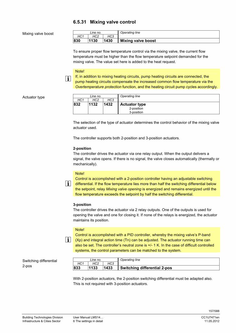
157/588
Building Technologies Division User Manual LMS14… CC1U7471en Infrastructure & Cities Sector 6 The settings in detail 11.05.2012
6.5.31 Mixing valve control
Line no. Operating line HC1 HC2 HC3
830 1130 1430 Mixing valve boost To ensure proper flow temperature control via the mixing valve, the current flow temperature must be higher than the flow temperature setpoint demanded for the mixing valve. The value set here is added to the heat request.
Note! If, in addition to mixing heating circuits, pump heating circuits are connected, the pump heating circuits compensate the increased common flow temperature via the Overtemperature protection function, and the heating circuit pump cycles accordingly.
Line no. Operating line
HC1 HC2 HC3
832 1132 1432 Actuator type 2-position 3-position
The selection of the type of actuator determines the control behavior of the mixing valve actuator used. The controller supports both 2-position and 3-position actuators. 2-position The controller drives the actuator via one relay output. When the output delivers a signal, the valve opens. If there is no signal, the valve closes automatically (thermally or mechanically).
Note! Control is accomplished with a 2-position controller having an adjustable switching differential. If the flow temperature lies more than half the switching differential below the setpoint, relay Mixing valve opening is energized and remains energized until the flow temperature exceeds the setpoint by half the switching differential.
3-position The controller drives the actuator via 2 relay outputs. One of the outputs is used for opening the valve and one for closing it. If none of the relays is energized, the actuator maintains its position.
Note! Control is accomplished with a PID controller, whereby the mixing valve’s P-band (Xp) and integral action time (Tn) can be adjusted. The actuator running time can also be set. The controller’s neutral zone is +/- 1 K. In the case of difficult controlled systems, the control parameters can be matched to the system.
Line no. Operating line
HC1 HC2 HC3
833 1133 1433 Switching differential 2-pos With 2-position actuators, the 2-position switching differential must be adapted also. This is not required with 3-position actuators.
Mixing valve boost
Actuator type
Switching differential 2-pos

158/588
Building Technologies Division User Manual LMS14… CC1U7471en Infrastructure & Cities Sector 6 The settings in detail 11.05.2012
Line no. Operating line
HC1 HC2 HC3
834 1134 1434 Actuator running time Set the running time of the actuator used with the mixing valve.
Line no. Operating line HC1 HC2 HC3
835 1135 1435 Mixing valve Xp The mixing valve's P-band Xp can be adjusted, thereby matching the control behavior of the valve's actuator to that of the plant (controlled system). The P-band influences the controller's P-control action.
Line no. Operating line HC1 HC2 HC3
836 1136 1436 Mixing valve Tn The mixing valve's integral action time Tn can be adjusted, thereby matching the control behavior of the valve's actuator to that of the plant (controlled system). The integral action time influences the controller's I-control action.
Actuator running time
Mixing valve Xp
Mixing valve Tn

159/588
Building Technologies Division User Manual LMS14… CC1U7471en Infrastructure & Cities Sector 6 The settings in detail 11.05.2012
6.5.32 Floor curing function
Line no. Operating line
HC1 HC2 HC3
850 1150 1450 Floor curing function Off
Functional heating
Curing heating
Functional/curing heating
Curing/functional heating
Manually The Floor curing function ensures controlled drying of the floor. It controls the flow temperature according to a certain temperature profile. Drying of the floor is effected via the floor heating system and the mixing or pump heating circuit. Any overtemperatures in the case of pump heating circuits can be prevented by overtemperature protection (pump cycling) or the temperature limiter.
Note! In the event of a power failure, the Floor curing function is resumed where operation had stopped.
Off Function is deactivated. Functional heating The first part of the temperature profile is completed automatically. Curing heating The second part of the temperature profile is completed automatically. Functional/curing heating The entire temperature profile (first and second part) is completed automatically. Curing/functional heating The entire temperature profile (first and second part) is completed automatically. Manually It is not a temperature profile that is completed, but the floor setpoint is controlled manually.
Warning! Observe the relevant standards and regulations specified by the floor
manufacturer Proper functioning is ensured only when the plant is correctly installed
(hydraulic system, electrical installation, settings)! If not observed, the floor might be damaged
The function can be aborted by selecting Off Maximum limitation of flow temperature remains active
Floor curing function

160/588
Building Technologies Division User Manual LMS14… CC1U7471en Infrastructure & Cities Sector 6 The settings in detail 11.05.2012
50
45
40
35
30
205 10 15 18 [Day]0
25
55
Fh Bh
1 15 7
Fh + Bh
1 25
Figure28: Floor curing function
Key
Line no. Meaning HC1 HC2 HC3
8744 8774 8803 TVw Flow temperature setpoint 1/2/3 Bh Curing heating Fh Functional heating X Start day
The temperature change always takes place at midnight. The start day (day 0), that is, the period of time from activation of the function to midnight, does not count as a functional day. The setpoint used for the start day is the value of the first functional day. During Floor curing, the profile temperature (TVEp) is limited within the 2 values Flow temp setpoint max (TVmax) and Flow temp setpoint min (TVmin). The function is ended when the functional days have elapsed or when deactivated via parameterization.

161/588
Building Technologies Division User Manual LMS14… CC1U7471en Infrastructure & Cities Sector 6 The settings in detail 11.05.2012
If the floor curing function is active in one of the heating circuits, a flow temperature increase based on a modulating pump is not calculated for that heating circuit. The modulating pump (heating circuit or boiler pump) is controlled to the parameterized maximum speed.
Line no. Operating line
HC1 HC2 HC3
851 1151 1451 Floor curing setp manually The flow temperature setpoint for the Manual floor curing function can be set separately for each heating circuit.
TVL
d
Mh
BZ 741BZ 1041BZ 1341
0 1 25BZ 740BZ 1040BZ 1340
BZ 851 / BZ 1151 / BZ 1451
25°C
7471d18/0910 Figure29: Floor curing setpoint manually
Key
Line no. Meaning HC1 HC2 HC3
741 1041 1341 TVmax Maximum flow temperature setpoint 740 1040 1340 TVmin Minimum flow temperature setpoint 851 1151 1451 TVEm Floor curing setpoint manually TVL Flow temperature
Mh Manual heating (functional heating + curing heating = 25
days) d Days
The function is ended when the functional days (manual heating) have elapsed or when deactivated via parameterization. The start day (day 0) does not count as a functional day. Floor curing setp manually (TVEm) can only be adjusted within the 2 limit values Flow temp setpoint max (TVmax) and Flow temp setpoint min (TVmin).
Line no. Operating line
HC1 HC2 HC3
855 1155 1455 Floor curing setp current Shows the current flow temperature setpoint while the Floor curing function is in progress.
Line no. Operating line
HC1 HC2 HC3
856 1156 1456 Floor curing day current Shows the current weekday of the Floor curing function in progress.
Modulating pump
Floor curing setp manually
Floor curing setp current
Floor curing day current

162/588
Building Technologies Division User Manual LMS14… CC1U7471en Infrastructure & Cities Sector 6 The settings in detail 11.05.2012
6.5.33 Forced signal and locking signal
Line no. Operating line
HC1 HC2 HC3
861 1161 1461 Excess heat draw Off
Heating mode
Always Excess heat draw can be triggered by the following functions: - Inputs Hx - Storage tank recooling - Solid fuel boiler excess heat draw When dissipation of excess heat is activated, it can be drawn by space heating. This can be selected separately for each heating circuit. Off Excess heat draw is deactivated. Heating mode Excess heat is drawn only when the controller operates in Heating mode. Always Excess heat is drawn in all operating modes.
6.5.34 Buffer storage tank/primary controller
Line no. Operating line HC1 HC2 HC3
870 1170 1470 With buffer No
Yes If there is a buffer storage tank, select whether the heating circuit can draw heat from it. When using alternative heat sources, the buffer storage tank temperature is used as a control criterion for the release of additional heat sources.
Line no. Operating line HC1 HC2 HC3
872 1172 1472 With prim contr/system pump No Yes
Enter whether the heating circuit receives its heat via the primary controller or with the help of the system pump (depending on the type of plant).
Excess heat draw
With buffer
With prim contr/system pump

163/588
Building Technologies Division User Manual LMS14… CC1U7471en Infrastructure & Cities Sector 6 The settings in detail 11.05.2012
6.5.35 Speed-controlled pump
Line no. Operating line HC1 HC2 HC3
880 1180 1480 Pump speed reduction Operating level Characteristic
Speed reduction of the heating circuit pump can be effected based on the operating level or the characteristic. Operating level When using this option, the speed of the heating circuit pump is calculated based on the operating level. The pump is controlled according to the Comfort level (incl. optimization) or – during the time the Floor curing function is active – with the parameterized maximum speed. In the case of the Reduced operating level, the pump is controlled to the parameterized minimum speed. Characteristic The speed of the heating circuit pump is calculated based on the flow temperature effectively received and the current flow temperature setpoint. The current temperature of the common flow is used as the actual value. If no common flow sensor is installed, the actual value of the boiler flow temperature is used. The actual value is damped by a filter (time constant can be parameterized). During the time the floor curing function is active, pump control ensures operation at the parameterized maximum speed.
Line no. Operating line HC1 HC2 HC3
881 1181 1481 Starting speed The speed of the heating circuit pump for the start kick can be defined here.
Line no. Operating line HC1 HC2 HC3
882 1182 1482 Pump speed min The minimum speed of the heating circuit pump can be defined here.
Line no. Operating line HC1 HC2 HC3
883 1183 1483 Pump speed max The maximum speed of the heating circuit pump can be defined here.
Line no. Operating line HC1 HC2 HC3
885 1185 1485 Pump speed min OEM The minimum speed of the heating circuit pump can be defined here.
Line no. Operating line HC1 HC2 HC3
886 1186 1486 Pump speed max OEM The maximum speed of the heating circuit pump can be defined here.
Pump speed reduction
Starting speed
Pump speed min
Pump speed max
Pump speed min OEM
Pump speed max OEM

164/588
Building Technologies Division User Manual LMS14… CC1U7471en Infrastructure & Cities Sector 6 The settings in detail 11.05.2012
Line no. Operating line
HC1 HC2 HC3
888 1188 1488 Curve readj at 50% speed Readjustment of the flow temperature setpoint when the pump speed is reduced by 50%. This readjustment is calculated based on the differential of flow temperature setpoint according to the heating curve and current room temperature setpoint.
Line no. Operating line HC1 HC2 HC3
889 1189 1489 Filter time const speed ctrl Here, the filter time constant for filtering the flow temperature is defined. The speed of the modulating pump is calculated based on this filtered flow temperature.
Line no. Operating line HC1 HC2 HC3
890 1190 1490 Flow setp readj speed ctrl No Yes
Here, it can be selected whether or not the calculated readjustment of the flow temperature setpoint shall be included in the request for heat. If the floor curing function is active in one of the heating circuits, the temperature request is not increased – irrespective of the parameter setting. No The request for heat remains unchanged. The calculated readjustment is not added. Yes The request for heat gives consideration to the calculated readjustment of the flow temperature setpoint.
Curve readj at 50% speed
Filter time const speed ctrl
Flow setp readj speed ctrl

165/588
Building Technologies Division User Manual LMS14… CC1U7471en Infrastructure & Cities Sector 6 The settings in detail 11.05.2012
6.5.36 Operating level changeover via input H
Line no. Operating line HC1 HC2 HC3
898 1198 1498 Operating level changeover Frost protection Reduced Comfort
The operating level to which the heating circuits shall be switched can be selected via an external time switch and inputs Hx.
6.5.37 Operating mode changeover via input H The heating circuit can be forced to adopt a selectable operating mode via input H by actuating a contact. The operating mode required when changeover takes place can be defined for each heating circuit via the Optg mode changeover (900/1200/1500). In that case, selection of the operating modes on the controller is disabled. The contact type can be set.
Line no. Operating line HC1 HC2 HC3
900 1200 1500 Optg mode changeover None Protection Reduced Comfort Automatic
None Function is deactivated.
Note! A basic unit with LPB device address = 1 can provide the function of central operating mode changeover. In that case, changeover on the central basic unit (via input H) also acts on the heating circuits and on DHW heating of the other basic units connected to LPB.
Line no. Operating line
6620 Action changeover functions
Operating level changeover
Optg mode changeover
Additional parameters

166/588
Building Technologies Division User Manual LMS14… CC1U7471en Infrastructure & Cities Sector 6 The settings in detail 11.05.2012
6.5.38 Behavior in the case of burner cycling When the burner shuts down, the amount of heat available is not sufficient after a certain time to satisfy the demand (actual value of flow temperature < flow temperature setpoint). Speed control would respond to this situation by increasing the pump’s speed. But this would lead to shorter burner off times. Also, due to pump modulation to a higher speed, the noise level would increase. For this reason, modulation of the heating circuit pump was matched to the situation of burner cycling. When the burner shuts down, the pump’s modulation is maintained at the parameterized minimum level. When the burner is switched on, the speed of the heating circuit pump remains unchanged for a selectable period of time. It is only on completion of this delay time that modulation of the heating circuit pump is again calculated and delivered based on the current common flow temperature (boiler flow temperature). This means that the pump’s speed is increased only if the filtered common flow temperature is lower than the flow temperature setpoint. An increase of the pump speed leads to longer burner on times. Then, filtering of the common flow temperature prevents the speed from dropping rapidly if the boiler temperature already lies above the setpoint, but the burner’s switch-off point is not yet reached. When the burner shuts down, the pump’s speed is reduced again to the parameterized minimum level.
Line no. Operating line HC1 HC2 HC3
[4291.1] [4291.2] [4291.3] Delay speed ctrl HCx
Here, the delay for speed control after Burner On can be set.
6.5.39 2-speed heating circuit pump This function facilitates the control of a 2-speed heating circuit pump, allowing the pump’s capacity to be lowered in Reduced mode (e.g. during night setback). To provide this function, a multifunctional relay output must be set to 2nd pump speed HC1/HC2/ HC3 (Q21, Q22, Q23). The second speed is switched on when the heating circuit’s operating level is Comfort (including optimization) or when the Floor curing function is active.
Relay HC pump (1st speed) Q2/Q6/Q20
Relay 2nd speed Q21/Q22/Q23
State
Off Off Off
On Off Low-fire
On On High-fire
Note! If the second speed needs a potential-free or inverted relay output, an intermediate relay is required.
Delay speed ctrl HCx

167/588
Building Technologies Division User Manual LMS14… CC1U7471en Infrastructure & Cities Sector 6 The settings in detail 11.05.2012
6.5.40 2-speed boiler pump This function affords control of a 2-speed boiler pump. Use of the second pump speed is made only if the first pump speed is activated. To enable the function, a multifunctional relay output must be set to the 2nd boiler pump speed Q27. The function supports 2 operating principles. Changeover of the operating principle is effected via Pump speed min (2322) and Pump speed max (2323): Operating principle 1 applies when: Pump speed max = Pump speed min Operating principle 2 applies when: Pump speed max > Pump speed min Operating principle 1: In DHW mode, the second speed of the boiler pump is always On. This also applies to pump overrun. In Heating mode, the second speed is used if at least one of the heating circuits calls for it. Operating principle 2: In principle, the 2-speed boiler pump can be regarded as a modulating pump with 3 speeds (Off/1st speed/2nd speed). For this reason, control is effected in accordance with PWM of the modulating boiler pump. When the first speed of the boiler pump is deactivated, the second speed is deactivated also. For changeover between the first and the second speed, a switching point with a hysteresis is calculated, depending on Pump speed min (2322) and Pump speed max (2323). Switching point = ((Pump speed max – Pump speed min)/2) + Pump speed min Hysteresis = (Pump speed max – Pump speed min)/20 The 2-speed boiler pump kicks its second speed – like the modulating boiler pump. Second speed On: Boiler pump speed >= switching point + hysteresis Second speed Off: Boiler pump speed <= switching point – hysteresis Line no. Operating line
2322 Pump speed min 2323 Pump speed max Line no. Operating line
8308 Boiler pump speed
Note! The speed of the boiler pump is displayed only if Function output P1 (6085) is set
to Boiler pump Q1. This parameterization is not required for the 2-speed boiler pump function
If the second speed needs a potentialfree or inverted relay output, an intermediate relay is required
Additional parameters
Info/Diagnostics
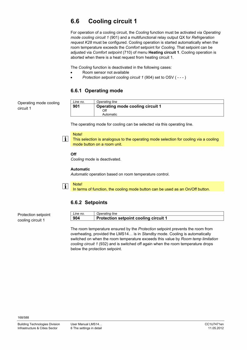
168/588
Building Technologies Division User Manual LMS14… CC1U7471en Infrastructure & Cities Sector 6 The settings in detail 11.05.2012
6.6 Cooling circuit 1 For operation of a cooling circuit, the Cooling function must be activated via Operating mode cooling circuit 1 (901) and a multifunctional relay output QX for Refrigeration request K28 must be configured. Cooling operation is started automatically when the room temperature exceeds the Comfort setpoint for Cooling. That setpoint can be adjusted via Comfort setpoint (710) of menu Heating circuit 1. Cooling operation is aborted when there is a heat request from heating circuit 1. The Cooling function is deactivated in the following cases: Room sensor not available Protection setpoint cooling circuit 1 (904) set to OSV ( - - - )
6.6.1 Operating mode
Line no. Operating line
901 Operating mode cooling circuit 1 Off Automatic
The operating mode for cooling can be selected via this operating line.
Note! This selection is analogous to the operating mode selection for cooling via a cooling mode button on a room unit.
Off Cooling mode is deactivated. Automatic Automatic operation based on room temperature control.
Note! In terms of function, the cooling mode button can be used as an On/Off button.
6.6.2 Setpoints
Line no. Operating line
904 Protection setpoint cooling circuit 1 The room temperature ensured by the Protection setpoint prevents the room from overheating, provided the LMS14… is in Standby mode. Cooling is automatically switched on when the room temperature exceeds this value by Room temp limitation cooling circuit 1 (932) and is switched off again when the room temperature drops below the protection setpoint.
Operating mode cooling circuit 1
Protection setpoint cooling circuit 1

169/588
Building Technologies Division User Manual LMS14… CC1U7471en Infrastructure & Cities Sector 6 The settings in detail 11.05.2012
6.6.3 Room temperature limitation
Line no. Operating line
932 Room temp limitation cooling circuit 1 Here, room temperature limitation acts like a switching differential. Cooling is switched on when the room temperature exceeds the current room temperature setpoint by the value set here. It is switched off again when the room temperature drops below the current room temperature setpoint.
EIN
TRKw
TRx
KAUS
°C
7471
z116
/0910
t
TRKw + SDR
Figure30: Room temperature limitation
Key Line no. Meaning
TRKw Room temperature setpoint cooling
TRx Actual value of room temperature
932 SDR Room temperature limitation
K Relay: Cooling request K28
t Time
Room temp limitation cooling circuit 1

170/588
Building Technologies Division User Manual LMS14… CC1U7471en Infrastructure & Cities Sector 6 The settings in detail 11.05.2012
6.7 DHW heating The LMS14… makes possible the following types of DHW heating: 1. Charging with oil- or gas-fired boiler 2. Charging with electric immersion heater 3. Charging with solar collectors 4. Charging with solid fuel boiler
Heat generation with an oil- or gas-fired boiler or electric immersion heater can be controlled. If there is demand for DHW, these heat sources can be switched on at any time. The strategy is to produce the amount of heat required at a certain point in time – and no more. For that purpose, switching programs, different setpoints and release criteria are available. If several heat sources and an electric immersion heater are available at the same time, they are used alternately, e.g. after summer/winter changeover. Heat generation with solar collectors and solid fuel boilers is not controllable. This means that with these types of heat sources, the DHW is not heated when there is demand, but when heat is available. The strategy is to fully charge the DHW storage tank whenever possible. Here, switching programs, setpoints and release criteria do not exist. Charging takes place whenever there is a sufficient temperature differential between solar collector or solid fuel boiler and storage tank, and when the DHW storage tank is not yet fully charged. Since it is not always possible to satisfy the total demand for heat via the solar collectors, the deficit must be covered by a controllable heat source (boiler or electric immersion heater). So boiler or electric immersion heater are only used to compensate for the heat deficit. This deficit is calculated from the storage tank’s current temperature and the required setpoint. In that case, the switching program and the release for recharging should become active during the night when it is certain that solar energy alone is not able to ensure the required temperature level.
Note! DHW storage tanks are usually designed such that the lower part of the tank is reserved for solar energy.
Warning! To prevent scalding, the pipe to the tap must have scalding protection integrated.
Charging with controllable heat sources
Charging with uncontrolled heat sources

171/588
Building Technologies Division User Manual LMS14… CC1U7471en Infrastructure & Cities Sector 6 The settings in detail 11.05.2012
6.7.1 DHW mode
Line no. Operating line
1600 Operating mode Off On Eco
Select the DHW mode with the operating mode button.
Note! DHW mode can also be influenced by operating mode changeover via inputs H1 up to H7.
Off Continuous operation, the setpoint being the DHW Frost Protection setpoint (5 °C). On DHW charging takes place automatically, the setpoint being the Nominal DHW setpoint or the Reduced DHW setpoint according to the selected kind of DHW release. Eco ECO mode is only used in connection with instantaneous water heaters. While the Keep hot function is generally enabled in On mode, it is deactivated in ECO mode. In connection with the aqua booster, ECO mode is always disabled.
Operating mode

172/588
Building Technologies Division User Manual LMS14… CC1U7471en Infrastructure & Cities Sector 6 The settings in detail 11.05.2012
6.7.2 Setpoints Different setpoints are available for DHW heating, with partly interlocked adjustability. Nominal setpoint max: Only used to provide maximum limitation of the Nominal
setpoint’s adjustability
Nominal setpoint: DHW setpoint during release times
Reduced setpoint: Backup temperature outside release times
Frost Protection setpoint: Frost Protection setpoint when DHW heating is Off. Not adjustable, fixed at 5 °C (factory setting)
The DHW setpoint acting on the control is selected based on the current operating level, which includes impact of the operating mode, the release (possibly the switching program), the DHW push and the Legionella function.
Line no. Operating line
1610 Nominal setpoint The DHW can be heated up according to different setpoints. These setpoints are activated depending on the selected operating mode, thus leading to different temperature levels in the DHW storage tank.
0 10 20 30 40 50 60 70 80 90 100 °C
1612 1610
1614
74
71
z91
/09
10
Figure31: Nominal setpoint
Key
Line no. Meaning
1614 TWWmax Maximum nominal DHW setpoint
1610 TWWN Nominal DHW setpoint
1612 TWWR Reduced DHW setpoint
Line no. Operating line
1612 Reduced setpoint Reduced setpoint: Backup temperature outside release times.
Line no. Operating line
1614 Nominal setpoint max This setting ensures maximum limitation of the Nominal setpoint (1610).
Nominal setpoint
Reduced setpoint
Nominal setpoint max

173/588
Building Technologies Division User Manual LMS14… CC1U7471en Infrastructure & Cities Sector 6 The settings in detail 11.05.2012
6.7.3 Holiday program If the holiday program is active with all heating circuits (Automatic operation and holiday program active), the DHW setpoint is set to the Frost protection level and the circulating pump is deactivated. At the end of the holiday period, the operating level according to the release applies again. While the holiday program is active, DHW heating can be triggered at any time by making a manual DHW push (one-time DHW charging to the Nominal setpoint).
Note! If the Legionella function was not effected because of a holiday period, it will be performed the next time DHW is heated to the Nominal setpoint.

174/588
Building Technologies Division User Manual LMS14… CC1U7471en Infrastructure & Cities Sector 6 The settings in detail 11.05.2012
6.7.4 DHW release
Line no. Operating line
1620 Release 24h/day Time programs HCs Time program 4/DHW
When DHW heating is On, the release parameter can be used to determine when – within a 24-hour period – DHW charging shall take place.
Note! The time of release does not apply to DHW charging with the electric immersion heater. A specific parameter is used for release of the electric immersion heater (refer to chapter Electric immersion heater).
DHW heating can be released in 3 different ways: 24h/day When this setting is used, DHW heating is continuously released as long as it is On. The DHW setpoint is always the Nominal setpoint, unless the Legionella function has been activated. Setting Once/day or Several times/day has no impact. When DHW heating is Off, the Frost Protection setpoint applies. Example:
0 6 12 18 24 h
Figure32: DHW release – 24h/day
Time programs HCs When this setting is used, DHW heating is released during the occupancy times of the connected heating circuits. If at least one of the heating circuits operates at the Comfort level, DHW heating is released also. If all heating circuits operate at the Reduced level or in Protection mode, the DHW level is set to Reduced also.
Note! Evaluated are the time programs of the heating circuits. If the heating circuits are switched off due to active ECO functions, DHW release is still maintained.
To ensure that the DHW storage tank is already charged when space heating is started, the release of DHW heating is brought forward in time against the switch-on point for space heating (including optimum start control). The extent of forward shift depends on Charging (5010) (Once/day or Several times/day). When selecting Once/day, the forward shift for the release of DHW heating is 2.5 hours. When selecting Several times/day, the forward shift for the release of DHW heating is 1.0 hour.
Release

175/588
Building Technologies Division User Manual LMS14… CC1U7471en Infrastructure & Cities Sector 6 The settings in detail 11.05.2012
If the Legionella function is pending, it will be performed when DHW heating is released for the first time in the morning. When DHW heating is Off, the Frost Protection setpoint applies. Example:
0 5 6 12 16 17 24 h
Figure 33: DHW release – time programs HCs
Time program 4/DHW When using this setting, a specific time program is available for DHW heating. For every weekday, a time program with a maximum of 3 on phases can be set. During the release time, the Nominal DHW setpoint applies, outside the release time, the Reduced DHW setpoint. If the Legionella function is pending, it will be performed when DHW heating is released for the first time in the morning. Setting Once/day or Several times/day has no impact. When DHW heating is Off, the Frost Protection setpoint applies. Example:
0 6 12 18 24 h Figure 34: DHW release – time program 4/DHW

176/588
Building Technologies Division User Manual LMS14… CC1U7471en Infrastructure & Cities Sector 6 The settings in detail 11.05.2012
6.7.5 Priority
Line no. Operating line
1630 Charging priority Absolute Shifting None MC shifting, PC absolute
When both space heating and DHW heating call for heat, the DHW priority function ensures that while DHW charging is in progress, the boiler’s capacity is used primarily for DHW heating.
Note! On applications with diverting valves, the function is automatically deactivated.
Absolute Mixing and pump heating circuits stay locked until DHW heating is completed. Shifting If the capacity of the heat source is not sufficient, the mixing and pump heating circuits will be restricted until the DHW is heated up. None DHW heating and space heating take place at the same time. In the case of tightly sized boilers and mixing heating circuits, the DHW setpoint may not be reached if space heating calls for considerable amounts of heat. MC shifting, PC absolute The pump heating circuits stay locked until the DHW storage tank is heated up. If the capacity of the heat source is not sufficient, the mixing heating circuits will be restricted also.
6.7.6 Locking signals Locking signals are used by the heat source to reduce or prevent heat consumption by the consumers. If the locking signal exceeds 50%, the DHW charging pump is deactivated. It will be activated again when the locking signal drops below the threshold value of 50%. Also, the heat source can calculate a critical locking signal based on a parameterized maintained boiler return temperature. The impact on the DHW charging pump is the same as with locking signal Boiler protection.
Charging priority

177/588
Building Technologies Division User Manual LMS14… CC1U7471en Infrastructure & Cities Sector 6 The settings in detail 11.05.2012
6.7.7 Forced signals If required, the heat source can send forced signals to its consumers. When the heat source delivers a valid forced signal, the DHW setpoint is set to the Legionella setpoint and – if the DHW temperature is lower – the charging pump is activated. When the forced signal becomes invalid, the charging pump is deactivated again and the DHW setpoint will be reset to the normal setpoint.
6.7.8 Pump overrun On completion of DHW charging, the charging pump continues to operate for the parameterized DHW overrun time. If none of the other consumers draws significant amounts of heat, the heat source can generate a forced Overrun signal for the boiler pump during that period of time. The overrun time can be set via the heat source parameters. On applications with diverting valve, the boiler pump overruns. The diverting valve maintains the DHW charging position during the overrun time. Pump overrun can be aborted by Discharging protection after DHW charging.

178/588
Building Technologies Division User Manual LMS14… CC1U7471en Infrastructure & Cities Sector 6 The settings in detail 11.05.2012
6.7.9 Legionella function
Line no. Operating line
1640 Legionella function Off Periodically Fixed weekday
When the Legionella function is activated, the DHW storage tank temperature is periodically raised to the Legionella funct setpoint. The Legionella funct setpoint can be maintained during the set dwelling time. Off Function is deactivated. Periodically The Legionella function is repeated according to the period (Legionella funct periodically 1641)). If the Legionella setpoint is attained via solar heating – independent of the selected interval – the time period is started again. This means that the heat source is switched on only if the solar plant was not able to ensure the required Legionella funct setpoint within the set period of time. Fixed weekday (The Legionella function can be activated on a fixed Legionella funct weekday (1642)). When using this setting, heating up to the Legionella setpoint takes place on the selected weekday, independent of previous storage tank temperatures. This setting is intended primarily for plant without solar integration.
Note! Delayed start of Legionella function: In connection with DHW storage tanks, the Legionella function is started 1 hour after power ON at the earliest.
Warning! During the time the Legionella function is performed, there is a risk of scalding when opening the taps.
Line no. Operating line
1641 Legionella funct periodically Setting Legionella funct periodically is used to select the number of weekdays after which the function shall be activated again. (This setting is active only if Legionella function (1640) is set to Periodically).
Note! If, in addition to a controllable heat source (oil- or gas-fired boiler, electric immersion heater, heat pump), the DHW storage tank is charged by a non-controllable heat source (solar plant, wood-fired boiler), the Legionella function can be activated at any time, depending on the availability of alternative energy. With this type of plant, it can be useful not to set a fixed weekday but to enter a minimum period of time to perform the Legionella function. If, for example, the function shall be effected every 5 days, but the solar plant raises the storage tank temperature to the Legionella funct setpoint after only 3 days, the 5-day period is restarted.
Legionella function
Legionella funct periodically

179/588
Building Technologies Division User Manual LMS14… CC1U7471en Infrastructure & Cities Sector 6 The settings in detail 11.05.2012
Line no. Operating line
1642 Legionella funct weekday Monday...Sunday
This function is used to select the weekday the function shall be performed. The function is then effected on the selected weekday, independent of the availability of alternative energy.
Line no. Operating line
1644 Legionella function time The Legionella function is started at the set time. The DHW setpoint is raised to the adjusted Legionella setpoint and DHW charging is started. If no time is parameterized, the Legionella function is started on the respective day together with the first normal release of DHW heating. If no release of DHW heating is scheduled for that day (continuously reduced), the Legionella function is performed at 24:00. If DHW heating is Off (DHW operating mode button = Off, or holidays), the Legionella function is effected whenever DHW heating is switched on again (DHW operating mode button = On, and end of holiday period).
Line no. Operating line
1645 Legionella funct setpoint The higher the temperature level of the storage tank, the shorter the required dwelling time at that level.
Storage tank temperature
Dwelling time
80 °C A few seconds
70 °C 1 minute
66 °C 2 minutes
60 °C 32 minutes
55 °C 6 hours
50 °C No killing of viruses
45 °C Ideal conditions for viruses
Warning! The figures given in the table are guide values. They do not guarantee that legionella viruses will be completely killed.
Note! The Legionella setpoint can be adjusted between 55 °C and 95 °C. When the Legionella function is activated, the DHW storage tank is heated up until the value set here is reached. For the Legionella function to be regarded as fulfilled, sensor B3 at the top or both sensors B3 and B31 must reach the Legionella setpoint which must be maintained for the set dwelling time, depending on Type of charging (5022).
Legionella funct weekday
Legionella function time
Legionella funct setpoint
Guide values

180/588
Building Technologies Division User Manual LMS14… CC1U7471en Infrastructure & Cities Sector 6 The settings in detail 11.05.2012
Line no. Operating line
1646 Legionella funct duration The demanded Legionella funct setpoint must be fully maintained during the set dwelling time. If the storage tank temperature (in the case of 2 sensors, the temperature acquired by the colder sensor) exceeds the Legionella funct setpoint minus 1 K, the Legionella funct setpoint is considered fulfilled and the Dwelling time timer elapses. If the storage tank temperature drops below the demanded Legionella funct setpoint by more than the DHW switching differential plus 2 K before the dwelling time has elapsed, the dwelling time must be fulfilled again. If no dwelling time is set, the Legionella function is performed the moment the Legionella funct setpoint is reached.
Note! If the Legionella function cannot be performed within a 48-hour period, an error message is delivered.
Line no. Operating line
1647 Legionella funct circ pump Off On
During the time the Legionella function is performed, the DHW circulating pump can be activated. Off Function is deactivated. On Function is activated. When the function is activated, the circulating pump is switched on while the Legionella function is performed as soon as the storage tank temperature (in the case of 2 sensors the temperature acquired by the colder sensor) lies above the Legionella funct setpoint minus 1 K. The pump runs during the set dwelling time. If the storage tank temperature falls below the required Legionella funct setpoint by more than the DHW switching differential plus 2 K, the circulating pump is deactivated.
Note! Periodic Legionella function: If the Legionella funct setpoint is reached via a non-controllable heat source (solar or wood-fired boiler), the circulating pump is activated for the demanded dwelling time. The Legionella function is performed a maximum of 3 days before the calculated day for fighting legionella. When the Legionella function is completed (parameterized dwelling time reached), the set Legionella funct duration commences again.
Warning! During the time the Legionella function is effected, there is a risk of scalding when opening the taps.
Legionella funct duration
Legionella funct circ pump

181/588
Building Technologies Division User Manual LMS14… CC1U7471en Infrastructure & Cities Sector 6 The settings in detail 11.05.2012
6.7.10 Circulating pump The circulating pump is controlled by a multifunctional relay. The relay must be appropriately parameterized.
Line no. Operating line
1660 Circulating pump release Time program 3/HC3 DHW release Time program 4/DHW Time program 5
The circulating pump runs during the release time (see below), provided DHW heating is On and at least one of the connected heating circuits is not in Holiday mode. If DHW mode is Off, or if all connected heating circuits are in Holiday mode, the circulating pump remains deactivated, independent of the parameterized release. Release of the circulating pump can take place in different ways: Time program 3/HC3 The circulating pump is released according to Time program 3/Heating circuit 3. DHW release When using this setting, the circulating pump is released when DHW heating is released also.
Note! Release of DHW heating can be set with a specific release parameter.
Time program 4/DHW The circulating pump is released according to Time program 4/DHW. Time program 5 The circulating pump is released according to Time program 5.
Circulating pump release

182/588
Building Technologies Division User Manual LMS14… CC1U7471en Infrastructure & Cities Sector 6 The settings in detail 11.05.2012
Line no. Operating line
1661 Circulating pump cycling Off On
To minimize circulation losses, the circulating pump can be controlled in cycling mode. When the function is activated, the circulating pump is switched on for 10 minutes within the release time and then switched off again for 20 minutes.
Note! If the pump is activated due to the Legionella function, it does not cycle. When the Legionella function is deactivated, the pump runs continuously during the release time.
Off Function is deactivated. On Function is activated.
Line no. Operating line
1663 Circulating setpoint When using a circulation sensor, the circulating pump is activated within the release time whenever the temperature acquired by that sensor falls below the circulation value. The pump keeps running until the circulation value is reached again. The minimum on time is 10 minutes. At the top, the setting of the circulation value is limited by the nominal setpoint.
Note: When using a circulation sensor, the temperature acquired by it is also used for the legionella function (dwelling time).
6.7.11 Frost protection for the circulation pipe If the temperature acquired by the circulation sensor drops below the Frost protection level, the pump is also activated outside the release times until the Frost protection level of 5 °C is reached. The minimum on time is 10 minutes.
Note! This function is only available if a circulation sensor is connected.
Circulating pump cycling
Circulating setpoint

183/588
Building Technologies Division User Manual LMS14… CC1U7471en Infrastructure & Cities Sector 6 The settings in detail 11.05.2012
6.7.12 Operating mode changeover via input H
Line no. Operating line
1680 Optg mode changeover None Off On
In the case of external changeover via inputs Hx, the operating mode where changeover is to take place can be selected. None Function is deactivated. No changeover of operating mode. Off Operating mode is changed to Off. On Operating mode is changed to On.
Optg mode changeover

184/588
Building Technologies Division User Manual LMS14… CC1U7471en Infrastructure & Cities Sector 6 The settings in detail 11.05.2012
6.8 Consumer circuit and swimming pool circuit
Line no. Operating line
VK1 VK2
1859 1909 Flow temp setp cons request
Line no. Operating line
SK
1959 Flow temp setp swi pool Set the flow temperature setpoint that becomes active when there is a request for heat from the consumer circuit or swimming pool circuit.
Line no. Operating line
VK1 VK2 SK
1874 1924 1974 DHW charging priority No Yes
With this setting, the connected consumer circuit pump/swimming pool pump can be excluded from or included in the impact resulting from DWH charging priority. This means that in the case of ventilation applications, for instance, constant delivery of heat can be ensured without getting any impact from DHW charging priority. No
Line no. Operating line
VK1 VK2 SK
1875 1925 1975 Excess heat draw Off On
If excess heat draw is activated, the surplus heat can be delivered to the consumer circuits or to the swimming pool circuit. This can be selected separately for each consumer circuit or for the swimming pool circuit.
Line no. Operating line
VK1 VK2 SK
1878 1928 1978 With buffer No Yes
If a buffer storage tank is used, it is to be entered whether the consumer circuit or the swimming pool circuit is allowed to draw heat from the pump storage tank. When employing alternative heat sources, the buffer storage tank temperature is used as a control criterion for the release of additional heat sources.
Line no. Operating line
VK1 VK2 SK
1880 1930 1980 With prim contr/system pump No Yes
The setting made here defines whether the consumer circuit or the swimming pool circuit shall receive heat via the primary controller or the system pump (depending on the type of plant).
Flow temp setp cons request
Flow temp setp swi pool
DHW charging priority
Excess heat draw
With buffer
With prim contr/system pump

185/588
Building Technologies Division User Manual LMS14… CC1U7471en Infrastructure & Cities Sector 6 The settings in detail 11.05.2012
6.9 Swimming pool
6.9.1 Setpoints
Line no. Operating line
2055 Setpoint solar heating When making use of solar energy, the swimming pool is heated to this setpoint.
Note! Function Collector overtemp prot can put the collector pump back into operation until the maximum swimming pool temperature is reached.
Line no. Operating line
2056 Setpoint source heating When using other heat sources, the swimming pool is heated to this setpoint.
6.9.2 Priority
Line no. Operating line
2065 Charging priority solar Priority 1 Priority 2 Priority 3
Priority 1 Swimming pool charging has the first priority. Priority 2 Swimming pool charging has the second priority (after the buffer storage tank and the DHW storage tank). Priority 3 Swimming pool charging is effected without priority (after the buffer storage tank, the DHW storage tank, the heating circuits, and the consumer circuits).
Note! Release and priority can also be influenced via inputs Hx.
Setpoint solar heating
Setpoint source heating
Charging priority solar

186/588
Building Technologies Division User Manual LMS14… CC1U7471en Infrastructure & Cities Sector 6 The settings in detail 11.05.2012
6.9.3 Overtemperature protection
Line no. Operating line
2070 Swimming pool temp max If the swimming pool temperature reaches the limit set here, the collector pump is deactivated. It is released again only when the swimming pool temperature drops 1 °C below the maximum limit.
Figure 35: Overtemperature protection swimming pool temperature maximum
Key
Line no. Meaning
2070 TSbMax Maximum storage tank temperature (buffer/DHW/swimming pool)
8900 TSb Swimming pool temperature
6.9.4 Plant hydraulics
Line no. Operating line
2080 With solar integration No Yes
The setting made here decides whether the swimming pool can be heated by solar energy.
Swimming pool temp max
With solar integration

187/588
Building Technologies Division User Manual LMS14… CC1U7471en Infrastructure & Cities Sector 6 The settings in detail 11.05.2012
6.10 Primary controller/system pump 6.10.1 Limitations of the flow temperature setpoint
Line no. Operating line
2110 Flow temp setpoint min 2111 Flow temp setpoint max
These limitations can be used to define a range for the flow temperature setpoint in Heating mode.
0 10 20 30 40 50 60 70 80 90 100
TV
max
min
act
°C
8931
2110
2111
74
71z
96
e/1
21
0
Figure 36: Primary controller/system pump flow temperature setpoint minimum/maximum
Key Line no. Meaning
8931 TVw Precontroller setpoint
Line no. Operating line
2121 Syst pump on heat gen lock Off On
This parameter is used to select whether or not the system pump shall be locked when the heat generation lock is active. Off The system pump is also locked when the heat generation lock is active. On The system pump is not locked when the heat generation lock is active.
Warning! Due to the locked system pump in the case of heat generation lock (System pump on heat gen lock (2121) set to Off), frost protection requests from consumers downstream from the system pump cannot be satisfied while heat generation lock is active. Also, cold water from these consumers is prevented from reaching the boiler to ensure it does not trigger frost protection for the boiler. Also refer to chapter Boiler pump, parameter Boiler pump on heat gen lock (2301).
Note! Due to the locked system pump resulting from heat generation lock (System pump on heat gen lock (2121) set to Off), the system pump is also locked when a solid fuel boiler meets the request for heat and Locks other heat sources (4102) is set to On. In that case, consumers downstream from the system pump do not receive any heat.
Flow temp setpoint min/max
Syst pump on heat gen lock

188/588
Building Technologies Division User Manual LMS14… CC1U7471en Infrastructure & Cities Sector 6 The settings in detail 11.05.2012
6.10.2 Mixing valve control
Line no. Operating line
2130 Mixing valve boost To ensure accurate control, the flow temperature delivered by the boiler must be higher than the flow temperature setpoint demanded downstream from the mixing valve. For this reason, the controller generates the boiler temperature setpoint based on the mixing valve boost set here and the current flow temperature setpoint.
Line no. Operating line
2132 Actuator type 2-position 3-position
The selected type of actuator determines the control action of the mixing valve actuator used. 2-position The controller drives the actuator via one relay output. When a control signal is delivered, the valve opens. When there is no control signal, the valve closes automatically (thermal or mechanical action).
Note! The control employs a 2-position controller with an adjustable switching differential. If the flow temperature lies more than half the switching differential below the setpoint, relay Mixing valve Open is energized to remain energized until the flow temperature reaches a level half the switching differential above the setpoint.
3-position The controller drives the actuator via 2 relay outputs. One of the outputs is used for opening the valve, the other for closing it. If none of the relays is energized, the actuator maintains its present position.
Note! The control employs a PID controller whose proportional band (Xp) and integral action time (Tn) can be parameterized. The actuator’s running time can also be adjusted. The controller’s neutral zone is +/- 1 K. The control parameters can be matched to the requirements of difficult controlled systems.
Line no. Operating line
2133 Switching differential 2-pos With 2-position actuators, the 2-position switching differential must be adapted also. This is not required with 3-position actuators.
Line no. Operating line
2134 Actuator running time Setting the running time of the actuator used with the mixing valve.
Line no. Operating line
2135 Mixing valve Xp By setting the right proportional band Xp, the control action of the mixing valve’s actuator is matched to the behavior of the plant (controlled system). The proportional band influences the controller’s P-control action.
Mixing valve boost
Actuator type
Switching differential 2-pos
Actuator running time
Mixing valve Xp

189/588
Building Technologies Division User Manual LMS14… CC1U7471en Infrastructure & Cities Sector 6 The settings in detail 11.05.2012
Line no. Operating line
2136 Mixing valve Tn By setting the right integral action time Tn, the control action of the mixing valve's actuator is matched to the behavior of the plant (controlled system). The integral action time influences the controller’s I-control action.
6.10.3 Plant hydraulics
Line no. Operating line
2150 Primary contr/system pump Before buffer After buffer
If the plant is equipped with a buffer storage tank, it must be entered here whether – hydraulically speaking – the primary controller or the system pump is located upstream of or downstream from the buffer storage tank.
Mixing valve Tn
Primary contr/system pump

190/588
Building Technologies Division User Manual LMS14… CC1U7471en Infrastructure & Cities Sector 6 The settings in detail 11.05.2012
6.11 Boiler
6.11.1 Release threshold Outside temperature Release of the boiler can be effected as a function of the outside temperature.
Line no. Operating line
2203 Release below outside temp The boiler is put into operation only when the composite outside temperature lies below this threshold. The setting range is from -50 to 50 °C. For the release, the calculation is based on a fixed switching differential of 0.5 K.
6.11.2 Full charging of buffer storage tank
Line no. Operating line
2208 Full charging buffer Off On
Function Full charging buffer makes it possible to switch off released heat sources only when the buffer storage tank is fully charged, despite automatic heat generation lock. But full charging must be demanded by the buffer storage tank. If and when the buffer storage tank shall call for full charging can be set via Full charging (4810). When the function is activated, the heat source is switched off only when full charging is ended or if, due to control of the burner, switching off must be effected. Heat sources that are not in operation are not switched on because full charging is required.
Release below outside temp
Full charging buffer

191/588
Building Technologies Division User Manual LMS14… CC1U7471en Infrastructure & Cities Sector 6 The settings in detail 11.05.2012
6.11.3 Setpoints The controlled boiler temperature setpoint can be limited by Setpoint min and Setpoint max. These limitations can be considered to be a protective function for the boiler. In normal operation, minimum limitation of the boiler temperature is the lower limit value for the controlled boiler temperature setpoint, depending on the boiler's operating mode. In normal operation, maximum limitation of the boiler temperature is the upper limit value for the controlled boiler temperature setpoint.
Note! The setting range of Setpoint min and Setpoint max is limited by Setpoint manual control.
120 °C
2213
2211
2210
2212
8 °C
Normal operating mode
Range of controlBoiler setpoint
747
1z97
e/1
210
Figure 37: Boiler setpoints
Key
Line no. Meaning
2210 Setpoint minimum
2211 Setpoint minimum OEM
2212 Setpoint maximum
2213 Setpoint maximum OEM

192/588
Building Technologies Division User Manual LMS14… CC1U7471en Infrastructure & Cities Sector 6 The settings in detail 11.05.2012
Line no. Operating line
2210 Setpoint min 2211 Setpoint min OEM 2212 Setpoint max 2213 Setpoint max OEM
The upper setpoint level for the boiler is defined via the limit value of the electronic temperature controller: All setpoints and switch-on/switch-off thresholds are limited such that (cutout temperature limit thermostat) – 3 K is the resulting maximum switch-off threshold. As a result, the requested setpoint is reduced to Maximum Switch-off threshold – switch-off differential. The switch-on threshold is reduced to Maximum Switch-off threshold – switch-off differential – switch-on differential. When the switching thresholds and the setpoint have been redefined, a check is made to see whether the switch-on threshold satisfies at least the requirement of minimum limitation. If the switch-on threshold is lower, it is raised to the minimum limitation. Setpoint and switch-off threshold are not readjusted here. Due to unfavorable parameterization of Minimum boiler temperature, Maximum boiler temperature safety limit thermostat and Switching differentials, a situation might now occur where the switch-on threshold lies above the setpoint or above the switch-off threshold. For this reason, the last adaption step makes certain that the switch-on threshold lies at least 2 K below the switch-off threshold. And the setpoint is not changed anymore.
Prelimitation Postlimitation
2531 SdOff
SdOn
2210
TKOff
8311
TKOnSdOff
TKOff
8311
TKOn
3 K
>2 K
7471d13e/1210 Figure 38: Boiler setpoints OEM
Key
Line no. Meaning
2210 Setpoint minimum
2531 Cutout temperature limit thermostat
8311 TKSoll Boiler temperature setpoint
TKAus Switch-off threshold boiler
TKEin Switch-on threshold boiler
SdAus Dynamic switch-off threshold (heating circuit/DHW)
SdEin Switch-on threshold (heating circuit/DHW)
Setpoint min/max – min/max OEM

193/588
Building Technologies Division User Manual LMS14… CC1U7471en Infrastructure & Cities Sector 6 The settings in detail 11.05.2012
6.11.4 Setpoint manual control In Manual control mode, the common flow temperature setpoint can be set to a fixed value.
Line no. Operating line
2214 Setpoint manual control
The setpoint of manual control and the switch-on and switch-off thresholds are generated depending on the electronic temperature controller (Limit thermostat function (2310)):
Temperature controller On: Switch-off threshold: Setpoint of manual control Controller setpoint: Switch-off threshold – parameterized switch-off differential (can be dynamic) Switch-on threshold: Controller setpoint – parameterized switch-on threshold
Temperature controller Off: Switch-off threshold: Setpoint of manual control + parameterized switch-off differential (can be dynamic) Controller setpoint: Setpoint of manual control Switch-on threshold: Setpoint of manual control – parameterized switch-on threshold
Note! In addition, switching thresholds and setpoint can be limited by function Cutout temp LT.
Note! If dynamic switching limits are activated ((Dyn SD on setpoint change (2464), Min setpoint change dyn SD (2465), Dyn SD with HC/DHW change (2466), Dyn SD when burner on (2467)), they also apply to manual control.
Line no. Operating line
2464 Dynamic switching differential when setpoint changes
2465 Minimum setpoint change with dynamic switching differential
2466 Dynamic switching differential changeover heating circuit/DHW
2467 Dynamic switching differential when burner On
Setpoint manual control
Additional parameters

194/588
Building Technologies Division User Manual LMS14… CC1U7471en Infrastructure & Cities Sector 6 The settings in detail 11.05.2012
6.11.5 Frost protection for the boiler
Line no. Operating line
2217 Setpoint frost protection The setpoint for the boiler’s frost protection can be set by the OEM. Frost protection for the boiler is ensured, independent of heat requests or connected plant components. Therefore, boiler control checks frost protection autonomously and also causes the burner to be started up, if necessary. If there is no request for heat and the burner is Off, the frost protection threshold is used as the switch-on threshold. Frost protection for the boiler is activated whenever the boiler temperature drops below the Frost Protection setpoint. The switch-off threshold is determined as follows:
Switch-off threshold boiler = Frost protection setpoint + Switching diff on HCs (2454) + Switching diff off min HCs (2455)
The boiler temperature setpoint is determined as follows:
Boiler temperature setpoint = frost protection threshold + Switching diff on HCs (2454) + Switching diff off min HCs (2455)
If Ctrl boiler pump/DHW valve (5774) is set to All requests, the boiler pump runs during the time frost protection for the boiler is active. If set to Request HC1/DHW only, the boiler pump will not be activated. If the boiler pump ran during the time frost protection for the boiler was active, pump overrun is performed when frost protection for the boiler has ended. If Setpoint frost protection (2217) is set to OSV (- - -), frost protection for the boiler is not deactivated, but the frost protection setpoint is set to -20 °C.
Key Line no. Meaning
2454 SdHkEin Switch-on differential heating circuits
2455 SdHkAusMin Minimum switch-off differential heating circuits
5774 Control boiler pump/DHW diverting valve
Setpoint frost protection

195/588
Building Technologies Division User Manual LMS14… CC1U7471en Infrastructure & Cities Sector 6 The settings in detail 11.05.2012
6.11.6 PID control algorithm To parameterize the PID control algorithm, 2 sets of controller coefficients are available. One set is used for Heating mode, the other for drawing DHW from the instantaneous water heater or for charging a DHW storage tank (DHW). Control parameters for Heating mode:
Line no. Operating line
2233 P-band Xp HCs 2234 Int action time Tn HCs 2235 Der action time Tv HCs
Control parameters for DHW mode:
Line no. Operating line
2236 P-band Xp DHW 2237 Int action time Tn DHW 2238 Der action time Tv DHW
Line no. Operating line
2233 P-band Xp HCs 2236 P-band Xp DHW
P-band Xp defines the controller’s gain. A small Xp leads to higher burner fan speeds without changing the control offset T = (temperature setpoint – actual value of temperature).
Line no. Operating line
2234 Int action time Tn HCs 2237 Int action time Tn DHW
The integral action time Tn defines the controller’s rate of response when correcting proportional offsets. A shorter Tn leads to faster correcting actions.
Line no. Operating line
2235 Der action time Tv HCs 2238 Der action time Tv DHW
The derivative action time Tv determines the extent of after-effect of a spontaneous change of control offset. A short Tv only has a short-time impact on the manipulated variable.
P-band Xp HCs/DHW
Int action time Tn HCs/DHW
Der action time Tv HCs/DHW

196/588
Building Technologies Division User Manual LMS14… CC1U7471en Infrastructure & Cities Sector 6 The settings in detail 11.05.2012
6.11.7 Boiler/burner control
Line no. Operating line
2241 Burner running time min Here, set a period of time after burner startup during which the off time differential is increased by 50%. This means that with similar heating up processes, the 2-position controller switches off later. But this parameter setting does not guarantee continuous burner operation for the parameterized period of time. This option is used only when none of the 3 criteria for the dynamic switching differentials is parameterized: Dyn SD on setpoint change (2464), Dyn SD with HC/DHW change (2466), and Dyn SD when burner on (2467) are switched off. Switching diff off max HCs (2456) and Switching diff off max DHW (2462) for the maximum switch off differentials are thus deactivated. The switch-off threshold is calculated based on the switching thresholds of the respective Heating/DHW mode: Switch-off threshold = setpoint + (min. switch-off differential) * 1.5. Generally speaking, the use of dynamic switch-off thresholds seems more advantageous. For this reason, the minimum burner running time should be seen in the context of backward compatibility.
Line no. Operating line
2243 Burner off time min The minimum burner off time acts exclusively between successive startup cycles resulting from space heating requests. It locks the boiler for an adjustable time. This period of time is started after regular shutdowns or when the limit thermostat cuts out in Heating mode. The 2-position controller initiates new startups resulting from space heating requests only when this period of time has elapsed.
Burner running time min
Burner off time min

197/588
Building Technologies Division User Manual LMS14… CC1U7471en Infrastructure & Cities Sector 6 The settings in detail 11.05.2012
Line no. Operating line
2245 SD burner off time If SD burner off time is exceeded, the minimum off time is aborted. If a request for heat puts the burner into operation, the minimum off time is enabled, which means that it will commence the next time the 2-position controller or the limit thermostat initiates shutdown. In the event of shutdown initiated by the 2-position controller or limit thermostat, the minimum off time commences if previously enabled. If one of the following requests is received during the minimum off time, it is immediately processed: DHW request Frost protection for the boiler Controller stop function Chimney sweep function The minimum off time for heat requests continues to elapse in the background. Requests for heat cause the burner to restart when… the minimum off time has elapsed, the parameterized control deviation (SD burner off time) is exceeded.
Note! Calculation of the switching point for aborting the burner off time! In the case of a modulating heating circuit/boiler pump, limitation of the boiler temperature increase must be active. The reduced setpoint for limiting the boiler temperature increase is used.
6.11.8 Overtemperature protection If the burner shuts down or if the request for heat becomes invalid, a forced overrun signal is forwarded during the parameterized pump overrun time. If such a signal is received, consumer groups must not be shut down. During the time the forced signal is active, the mixing valve setpoint for flow temperature control is maintained at the former setpoint. If the last pending heat request was received from a DHW component (instantaneous water heater or storage tank), the overrun parameter for DHW heating is used for boiler pump Q1.
Line no. Operating line
2250 Pump overrun time Pump overrun time after Heating mode and external requests for heat.
Line no. Operating line
2253 Pump overr time after DHW Pump overrun time after DHW heating.
SD burner off time
Release of minimum off time
Start of minimum off time
Interruption of minimum off time
End of minimum off time
Pump overrun time
Pump overr time after DHW

198/588
Building Technologies Division User Manual LMS14… CC1U7471en Infrastructure & Cities Sector 6 The settings in detail 11.05.2012
6.11.9 Minimum limitation of boiler temperature
Line no. Operating line
2260 Prot boil startup consumers Off On
Protective startup with consumer pumps The consumer pumps (heating circuit pump, DHW charging pump, external load) are deactivated, or stay deactivated, if the locking signal exceeds the relevant value. Threshold value for heating circuit pump = 5% Threshold value for DHW charging pump = 50%
Note! If protective startup occurs during DHW charging with shifting DHW charging priority, the locking signal for shifting priority is set to 100%. This ensures that the DHW charging pump can be activated before the heating circuit pumps are put into operation.
Protective startup with consumer mixing valves When protective startup is activated, the consumers with mixing valve are restricted in their heat consumption in accordance with the locking signal value. The function can be deactivated. Off Function is deactivated. On Function is activated.
Prot boil startup consumers

199/588
Building Technologies Division User Manual LMS14… CC1U7471en Infrastructure & Cities Sector 6 The settings in detail 11.05.2012
Line no. Operating line
2263 Setpoint min on shutdown Off
On When this function is activated, the boiler also maintains its minimum temperature when – for certain periods of time – there are no more requests for heat from the consumers. If the burner is running, it is shut down only if the boiler temperature exceeds its minimum level. This means that when the requests for heat from the consumers are satisfied, the boiler temperature is at least at its minimum level. However, when there are no requests for heat from the consumers, the boiler is not maintained at the minimum temperature: If the boiler temperature drops below its minimum while the burner is Off, the burner is not put into operation.
Note! This functionality is not available for certain special hydraulic systems. With hydraulic configurations where the boiler pump is activated only if heating circuit 1 calls for heat, the boiler cannot be kept hot without getting a simultaneous request for heat from the consumer and without heat usage by the same consumer.
Off Function is deactivated. On Function is activated.
Line no. Operating line
2264 Prot boil startup anticipation When the burner is started up, the boiler temperature is expected to rise. If the rise is not sufficient, locking signals are forwarded to the consumers, requesting them to reduce their heat demand. This allows the boiler to reach the required temperature level more quickly. During protective boiler startup, the locking signal value to the consumers is calculated based on the anticipated progression of the boiler temperature. The anticipated boiler temperature at the current point in time + anticipation time are calculated as follows: Actual value of boiler temperature [taktuell+ tvoraus] = actual value of boiler temperature [taktuell] + (TKgradient * tvoraus) Eventually, the difference of anticipated boiler temperature and minimum boiler temperature determines the value of the locking signal (0…100%).
Setpoint min on shutdown
Prot boil startup anticipation

200/588
Building Technologies Division User Manual LMS14… CC1U7471en Infrastructure & Cities Sector 6 The settings in detail 11.05.2012
6.11.10 Minimum limitation of return temperature The required minimum setpoint of the return temperature can be parameterized. If the boiler return temperature drops below the setpoint, maintained boiler return temperature is activated. In connection with the maintained boiler return temperature, the following functions can be provided: Locking signal acting on the consumers Control of a modulating valve
Line no. Operating line
2270 Return setpoint min The required minimum return temperature setpoint can be parameterized. If the boiler return temperature falls below the return temperature setpoint, maintained boiler return temperature becomes active.
Line no. Operating line
2271 Return setpoint min OEM This minimum limitation of the return temperature OEM is the lower limit value for the minimum return temperature setpoint.
Line no. Operating line
2272 Return influence consumers Off On
If, with the boiler released, the return temperature falls below the set minimum temperature, a locking signal is calculated. With proper pump circuits (heating circuit pump, DHW charging pump, external load), the consumer pumps are deactivated, or stay deactivated, if the locking signal exceeds the relevant threshold value Off Function is deactivated. On Function is activated.
Return setpoint min
Return setpoint min OEM
Return influence consumers
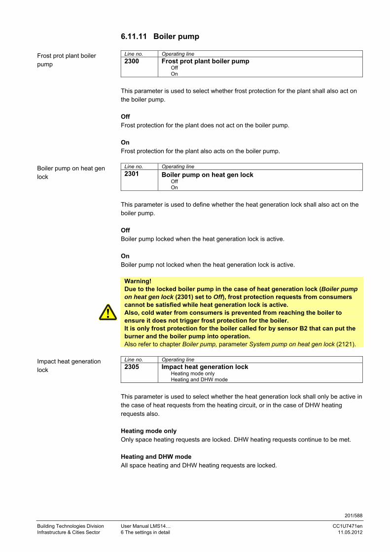
201/588
Building Technologies Division User Manual LMS14… CC1U7471en Infrastructure & Cities Sector 6 The settings in detail 11.05.2012
6.11.11 Boiler pump
Line no. Operating line
2300 Frost prot plant boiler pump Off On
This parameter is used to select whether frost protection for the plant shall also act on the boiler pump. Off Frost protection for the plant does not act on the boiler pump. On Frost protection for the plant also acts on the boiler pump.
Line no. Operating line
2301 Boiler pump on heat gen lock Off On
This parameter is used to define whether the heat generation lock shall also act on the boiler pump. Off Boiler pump locked when the heat generation lock is active. On Boiler pump not locked when the heat generation lock is active.
Warning! Due to the locked boiler pump in the case of heat generation lock (Boiler pump on heat gen lock (2301) set to Off), frost protection requests from consumers cannot be satisfied while heat generation lock is active. Also, cold water from consumers is prevented from reaching the boiler to ensure it does not trigger frost protection for the boiler. It is only frost protection for the boiler called for by sensor B2 that can put the burner and the boiler pump into operation. Also refer to chapter Boiler pump, parameter System pump on heat gen lock (2121).
Line no. Operating line
2305 Impact heat generation lock Heating mode only Heating and DHW mode
This parameter is used to select whether the heat generation lock shall only be active in the case of heat requests from the heating circuit, or in the case of DHW heating requests also. Heating mode only Only space heating requests are locked. DHW heating requests continue to be met. Heating and DHW mode All space heating and DHW heating requests are locked.
Frost prot plant boiler pump
Boiler pump on heat gen lock
Impact heat generation lock

202/588
Building Technologies Division User Manual LMS14… CC1U7471en Infrastructure & Cities Sector 6 The settings in detail 11.05.2012
6.11.12 Electronic temperature controller
Line no. Operating line
2310 Limit thermostat function Off On
Limit thermostat function only acts in connection with manual control. In all other operating situations, the function is deactivated. Off When the Limit thermostat function is deactivated, the maximum switch-off point is limited to the limit thermostat’s cutout temperature – 3 K, the maximum setpoint to the limit thermostat’s cutout temperature – 3 K – switch-off threshold. On When the Limit thermostat function is activated, maximum switch-off point and maximum setpoint are limited to the limit thermostat’s cutout temperature – 3 K.
Line no. Operating line
2531 Cutout temp LT
Limit thermostat function
Additional parameters

203/588
Building Technologies Division User Manual LMS14… CC1U7471en Infrastructure & Cities Sector 6 The settings in detail 11.05.2012
6.11.13 Limitation of boiler temperature increase Use of a speed-controlled pump in heating operation is aimed at meeting the request for heat at minimum pump speeds whenever possible. Reduced pump speeds lead to lower volumetric flow. To ensure that reduced volumetric flow is able to meet the demand for heat, the flow temperature must be increased. Also, reduced volumetric flow leads to lower return temperatures. Higher flow temperatures and lower return temperatures result in higher boiler temperature increases. To protect the boiler from thermal stress due to excessive boiler temperature increases, the increase is limited. This limitation is accomplished by limiting the boiler temperature setpoint as a function of the current return temperature. Limitation of the boiler temperature setpoint means that the flow temperature setpoint calculated for the heating circuit will not be reached. Speed control for the pump responds by increasing the speed. As long as the pump is not controlled to the maximum speed, the boiler temperature increase is limited to the parameterized nominal increase (Temp differential nominal (2317)). If the pump is already controlled to the maximum speed, the volumetric flow cannot be further increased. In that case, the boiler temperature increase is no longer limited to the nominal but to the maximum increase (Temp differential max (2316)). The transition from limitation to nominal boiler temperature increase aimed at limiting the maximum boiler temperature increase is made via the ramp in a linear manner. The slope of the ramp is determined by the time constant for speed control (Filter time const speed ctrl (889, 1189, 1489)). For the transition, the time constant is multiplied by 5. If the pump speed returns to a level below the maximum speed, the transition is made in the other direction with the same time constant.
Limitation of boiler temperature increase
2316
2317
Pump PWM
PWM-Max
PWM-Min
5*Filter time constant speed control
Time
Time
7471d70e/0911
Figure 39: Limitation of boiler temperature increase

204/588
Building Technologies Division User Manual LMS14… CC1U7471en Infrastructure & Cities Sector 6 The settings in detail 11.05.2012
Key
Line no. Operating line
HC1 HC2 HC3
889 1189 1489 Filter time constant speed control
Line no. Operating line
2316 Temp differential max
2317 Temp differential nominal
PWM-Min Parameterized minimum speed of heating circuit or boiler pump
PWM-Max Parameterized maximum speed of heating circuit or boiler pump
Limitation of the boiler temperature increase in connection with a speed-controlled pump (heating circuit or boiler pump) is only active in space heating mode. It is deactivated as soon as there a request for DHW heating. Prerequisite for limitation of the boiler’s temperature differential is a correctly working sensor B7 and a parameterized upper limit for the permitted boiler temperature differential: Temp differential max.
Line no. Operating line
2316 Temp differential max The maximum boiler temperature differential in connection with a speed-controlled heating circuit pump is maintained when the pump is controlled at the maximum permissible speed. The function can be deactivated by setting OSV (---).
Line no. Operating line
2317 Temp differential nominal In connection with a speed-controlled heating circuit pump and pure Heating mode, the nominal boiler temperature differential is maintained as long as the heating circuit pump is not controlled at the maximum permissible speed.
Temp differential max
Temp differential nominal

205/588
Building Technologies Division User Manual LMS14… CC1U7471en Infrastructure & Cities Sector 6 The settings in detail 11.05.2012
6.11.14 Speed control To calculate modulation of a speed-controlled boiler pump, several functions are available. The required function can be selected via parameter Pump modulation (2320).
Line no. Operating line
2320 Pump modulation None Demand Boiler setpoint Temp differential nominal Burner output
None No speed is selected for the boiler pump. The output delivers 0% PWM. Demand The speed of the boiler pump is calculated based on the speed requests from the consumers. Calculation of the speed is dependent on the consumers in the plant, the currently valid heat requests, and the pump speeds calculated by the individual consumers. Only consumers acting on the same controller are considered. When there is a request for DHW heating, the speed calculated for the DHW pump (charging pump Q3 or instantaneous water heater pump Q34) is used for the boiler pump. The speed limits of the DHW pump apply. If there is no request for DHW heating, the pump speed is calculated based on the speed requests from the heating circuits. The speed of the boiler pump results from the highest pump speed calculated by the heating circuits. The pump speed calculated by heating circuits 2 and 3 is evaluated only if these heating circuits are hydraulically dependent on the position of the diverting valve (Ctrl boiler pump/DHW valve (5774)) and thus on the boiler pump. The speed of the DHW or heating circuit pump is also used for the boiler pump. Hence, only the speed limits of the DHW pump or the respective heating circuit pump apply. In this case, the speed limits parameterized for the boiler pump are not considered. Line no. Operating line
5774 Ctrl boiler pump/DHW valve
Note! This function is only for use with single-boiler plants. For cascaded systems, one of the other functions must be selected.
Pump modulation
Additional parameters

206/588
Building Technologies Division User Manual LMS14… CC1U7471en Infrastructure & Cities Sector 6 The settings in detail 11.05.2012
Boiler setpoint With modulation based on the boiler temperature setpoint, the speed of the boiler pump is reduced to such a degree that the sensor B2 will reach the required boiler temperature setpoint. Reaching the boiler temperature setpoint is primarily the task of the boiler controller. Also, reaching this setpoint is dependent on the amount of water supplied by the boiler pump. The required boiler temperature setpoint can be attained more quickly if the amount of water supplied by the boiler pump is reduced. But if the amount of water supplied is reduced excessively, the boiler controller modulates the burner’s output down. In that case, the burner’s capacity would only be partly used. The speed of the boiler pump is calculated such that it can be lowered to the parameterized minimum only when the burner’s full capacity is reached. When the burner operates at low output (relative output below 66%), the setpoint for speed control is reduced by the parameterized difference (Pump setpoint reduction (2329)). If the relative burner output exceeds 66%, the setpoint for speed control is increased to such an extent that at 100% relative output, the setpoint for calculating the speed corresponds to the setpoint for boiler temperature control. This prevents the boiler from reaching the setpoint at a reduced output while the pump continues to operate at reduced speed. Speed control is ensured by a PID controller, using the controller coefficients for the boiler pump (Speed Xp (2324), Speed Tn (2325), and Speed Tv (2326)). For control of the pump speed with an active DHW heating request (in instantaneous water heater operation also), the parameterized speed limits for charging pump Q3 apply. With all the other heat requests (heating circuit, consumer circuit, zone extension), the speed limits parameterized for the boiler pump apply.
Setpoints
SetpointBoiler control
SetpointSpeed control
2329
0% 66% 100%Burner output7471d71e/0811
Figure 40: Speed control – boiler setpoint
Line no. Operating line
2324 Speed Xp 2325 Speed Tn 2326 Speed Tv 2329 Pump setpoint reduction
Additional parameters

207/588
Building Technologies Division User Manual LMS14… CC1U7471en Infrastructure & Cities Sector 6 The settings in detail 11.05.2012
Temp differential nominal The objective of this function is to modulate the speed of the boiler pump such that the boiler temperature increase is maintained at the level of the parameterized nominal increase (Temp differential nominal (2317)). The boiler temperature increase is the difference of return temperature (sensor B7) and flow temperature (sensor B2). If the current boiler temperature increase is greater than the nominal increase, speed control responds by increasing the pump speed and, on the other hand, by reducing the pump speed. The pump‘s speed is controlled by a PID controller based on the control coefficients for the boiler pump (Speed Xp (2324), Speed Tn (2325), and Speed Tv (2326)). Limitation of the pump speed results from the minimum and maximum speed parameterized for the boiler pump. In DHW heating operation, control of the boiler pump speed is not effected according to the parameterized boiler temperature increase. Here, the speed of the boiler pump is calculated based on the Demand function (see above). For all other operating modes – with the exception of DHW heating – following applies: If the boiler return temperature is not available (sensor faulty or not configured), or if no valid nominal boiler temperature increase is configured, the speed of the boiler pump is calculated based on the Boiler setpoint function. Line no. Operating line
2324 Speed Xp 2325 Speed Tn 2326 Speed Tv
Additional parameters

208/588
Building Technologies Division User Manual LMS14… CC1U7471en Infrastructure & Cities Sector 6 The settings in detail 11.05.2012
Burner output This function is suited for use with single-boiler plants and cascaded systems, with or without pressureless header. With this function, the speed of the boiler pump is directly dependent on the burner’s current output. When the burner operates at low output, the boiler pump is controlled at low speed, when the output is high, the boiler pump is controlled at high speed. The speed of the boiler pump is calculated based on the burner’s current output. As long as the burner’s output does not exceed the parameterized threshold (Output at pump speed min (2334)), the boiler pump is parameterized at minimum speed. When the burner’s output exceeds the parameterized threshold, the pump’s speed is raised as the burner’s output increases until, at the upper threshold (Output at pump speed max (2335)), the pump is parameterized at maximum speed. If the burner’s output increases further, the pump’s speed is maintained at its maximum.
Pump-PWM
PWM-max
PWM-min
2334 2335Burner output7471d72e/0811
Figure 41: Pump speed as a function of burner output
Key
Line no. Operating line
2334 Output at pump speed minimum
2335 Output at pump speed maximum
PWM-min Parameterized minimum speed of boiler pump
PWM-max Parameterized maximum speed of boiler pump
When calculating the pump speed, the burner’s output is attenuated with a time constant of 30 seconds. If the output changes abruptly, it can therefore take up to 3 minutes for the pump speed to be matched to the current burner output.

209/588
Building Technologies Division User Manual LMS14… CC1U7471en Infrastructure & Cities Sector 6 The settings in detail 11.05.2012
The PWM limits for the pumps on the Heating engineer level are either relative or absolute. The selection is made via factory settings at headquarters level. With absolute PWM limits, the setting range for the heating engineer is restricted by the OEM limits. This means that the heating engineer can vary the minimum speed only above the minimum set by the OEM, and the maximum speed only below the maximum set by the OEM. In the case of relative PWM limits, the speed range restricted by the OEM represents the basis for the heating engineer’s setting range which, here, always reaches from 0% to 100%, where 0% corresponds to the OEM’s minimum value and 100% to the OEM’s maximum value. Values between 0% and 100% restrict accordingly the speed range defined by the OEM. Here, the pump speed values displayed are not identical with the control values for the pump. For every pump, a set of 6 parameters are available for limiting the speed. These are the absolute min./max. values at the Heating engineer level, the relative min./max. values at the Heating engineer level, and the min./max. values at the OEM level. The parameters for the relative speed limits are not interlocked with the limits at the OEM level. The only active limitation is that between minimum and maximum values (minimum cannot be set above maximum, and vice versa).
Note! The setting limits at the OEM level are still confined by the parameters for the absolute speed limits at the Heating engineer level. This means that the upper speed limit at the OEM level cannot be set below the maximum value at the Heating engineer level. When using the relative PWM limits, it is therefore recommended to set both the low and the high speed limit at the Heating engineer level to 50%. Hence, the range from 0% to 50% is available for the lower OEM limit, and the range from 50% to 100% for the upper OEM limit.
Line no. Operating line
2321 Starting speed Starting speed of boiler pump.
Line no. Operating line
2322 Pump speed min For the modulating pump, the working range can be defined as a percentage of output. Internally, the control translates percentage figures to speed. The minimum value should be selected such that the pump is reliably activated when controlled.
Line no. Operating line
2323 Pump speed max Power consumption can be limited via the maximum value.
PWM limits relative/absolute
Starting speed
Pump speed min
Pump speed max

210/588
Building Technologies Division User Manual LMS14… CC1U7471en Infrastructure & Cities Sector 6 The settings in detail 11.05.2012
Line no. Operating line
2324 Speed Xp
Line no. Operating line
2325 Speed Tn
Line no. Operating line
2326 Speed Tv
Boiler pump speed range: The boiler pump speed is limited by a minimum and maximum permissible speed. To ensure reliable startup, the pump is started running at the parameterized starting speed for 10 seconds.
Line no. Operating line
2327 Pump speed min OEM Minimum limitation of pump speed at the OEM level.
Line no. Operating line
2328 Pump speed max OEM Maximum limitation of pump speed at the OEM level.
Line no. Operating line
2329 Pump setpoint reduction This parameter is used to set the setpoint reduction for the boiler pump’s speed control. This setpoint reduction is only active in connection with Pump modulation (2320).
Line no. Operating line
[6066.1] LimMinBoilPumpMod Off
On The burner shall be prevented from shutting down or the boiler temperature shall be prevented from exceeding the safety limiter thermostat cutout temperature due to residual heat because pump modulation is not sufficiently high. For this reason, the pump’s minimum permissible modulation is constantly adapted, depending on boiler temperature and burner modulation. This ensures that the modulating boiler pump operates above the parameterized minimum modulation when… - the burner is started with 100% burner modulation, - the burner reaches the switch-off threshold with burner modulation above the minimum output, - the boiler temperature lies above the switch-off threshold. Also, when the burner is switched on, the pump’s minimum modulation is limited to 100% for 10 seconds, thus setting modulation to the maximum. The function can be deactivated. Off Function is deactivated. On Function is activated.
Speed Xp
Speed Tn
Speed Tv
Pump speed
minimum/maximum
Pump speed min OEM
Pump speed max OEM
Pump setpoint reduction
LimMinBoilPumpMod

211/588
Building Technologies Division User Manual LMS14… CC1U7471en Infrastructure & Cities Sector 6 The settings in detail 11.05.2012
6.11.15 Output data
Line no. Operating line
2330 Output nominal
Line no. Operating line
2331 Output basic stage These settings are required when several boilers with different capacities operate in a cascaded system.
Line no. Operating line
2334 Output at pump speed min If option Pump modulation (2320) is selected, the boiler pump is operated at minimum speed until the burner output set on Output at pump speed min (2334) is reached, and at maximum speed from the burner output set on Output at pump speed max (2335). If the burner’s output lies between these 2 values, the boiler pump’s speed is calculated through linear conversion.
Line no. Operating line
2335 Output at pump speed max If option Pump modulation (2320) is selected, the boiler pump is operated at minimum speed until the burner output set on Output at pump speed min (2334) is reached, and at maximum speed from the burner output set on Output at pump speed max (2335). If the burner’s output lies between these 2 values, the boiler pump’s speed is calculated through linear conversion.
Output nominal
Output basic stage
Output at pump speed min
Output at pump speed max

212/588
Building Technologies Division User Manual LMS14… CC1U7471en Infrastructure & Cities Sector 6 The settings in detail 11.05.2012
6.11.16 Fan
Line no. Operating line
2441 Fan speed heating max This parameter is used to limit the maximum output in Heating mode.
Line no. Operating line
2442 Fan speed full charging max This parameter can be used to limit the maximum output with full charging in connection with stratification storage tanks.
Line no. Operating line
2443 Fan sp start value inst WH To ensure quick and stable control of the required output when DHW is consumed, a modulation start value for the instantaneous water heater can be preset. If, due to a small control deviation, the controller calls for a lower fan speed, this start value ensures that the fan is controlled to a lower speed. If evaluation of the control deviation demands a higher speed, the fan is controlled to a higher speed.
Line no. Operating line
2444 Fan speed DHW max This parameter is used to limit the maximum fan speed for DHW heating. The parameter is OSV-compatible. With OSV, the maximum fan speed applies to DHW heating.
Line no. Operating line
2445 Fan shutdown heating mode Off On
This parameter belongs to function Fan shutdown K38. This function is used to switch off the fan’s power supply. Power supply to the fan is released as soon as the fan’s PWM control is active or whenever there is a request for DHW. Fan shutdown is delayed and takes place after PWM control is switched off, or when there is no more demand for DHW. This delayed shutdown can be set via Fan shutdown delay (2446). During the time a request for DHW is active, the fan’s power supply also remains released when PWM control is inactive. Fan shutdown heating mode (2445) can be used to select whether the fan’s power supply shall also be released when there are requests for space heating, independent of PWM control. Off Function is deactivated. On Function is activated.
Fan speed heating max
Fan speed full charging max
Fan sp start value inst WH
Fan speed DHW max
Fan shutdown heating mode

213/588
Building Technologies Division User Manual LMS14… CC1U7471en Infrastructure & Cities Sector 6 The settings in detail 11.05.2012
Line no. Operating line
2446 Fan shutdown delay This parameter belongs to function Fan shutdown K38. This function is used to switch off the fan’s power supply. Power supply to the fan is released as soon as the fan’s PWM control is active or whenever there is a request for DHW. Fan shutdown is delayed and takes place after PWM control is switched off, or when there is no more demand for DHW. This delayed shutdown can be set via Fan shutdown delay (2446). During the time a request for DHW is active, the fan’s power supply also remains released when PWM control is inactive. Fan shutdown heating mode (2445) can be used to select whether the fan’s power supply shall also be released when there are requests for space heating, independent of PWM control.
Fan shutdown delay

214/588
Building Technologies Division User Manual LMS14… CC1U7471en Infrastructure & Cities Sector 6 The settings in detail 11.05.2012
6.11.17 Control of the boiler/burner The controller delay serves for stabilizing the combustion process, especially after a cold start. After the burner control’s release by the controller, the latter maintains the parameterized output for a predefined period of time. The modulating controller – and thus modulation – are released only when this period of time has elapsed. The following graph shows an example:
Output
Figure 42: Control of the boiler/burner
Key
Line no. Meaning
2452 LmodRgVz Controller delay speed
2453 ZReglVerz Controller delay duration
Via parameter is set to determine whether and how the controller delay shall act. The controller delay can be deactivated. Activation can take place in the case of heating requests only, DHW requests only, or both.
Note! During operation of the instantaneous water heater, the controller delay never takes effect.
The parameterized output in percent is limited to the available setting range of the respective operating mode (heating circuit/DHW). This means that in Heating mode, the parameterized Max fan speed heating mode is used as the 100% value. In DHW mode, the maximum output is used as the 100% value. Another parameter defines for what period of time the controller delay shall be active.

215/588
Building Technologies Division User Manual LMS14… CC1U7471en Infrastructure & Cities Sector 6 The settings in detail 11.05.2012
Line no. Operating line
2450 Controller delay Off
Heating mode only
DHW mode only
Heating and DHW mode
Here, you can set the operating mode where the controller delay shall become active. Off Function is deactivated. Heating mode only Controller delay only acts in Heating mode. DHW mode only Controller delay only acts in DHW mode. Heating and DHW mode Controller delay acts in Heating and DHW mode.
Line no. Operating line
2452 Controller delay speed Speed delivered during the controller delay time.
Line no. Operating line
2453 Controller delay duration Duration of controller delay. This delay time is started the moment a flame is definitively detected after ignition.
Controller delay
Controller delay speed
Controller delay duration

216/588
Building Technologies Division User Manual LMS14… CC1U7471en Infrastructure & Cities Sector 6 The settings in detail 11.05.2012
6.11.18 Dynamic switching differentials To avoid unnecessary cycling during startup, the switch-off differential is dynamically adapted, depending on the progression of temperature. As a matter of principle, the switch-off differential is reduced depending on the extent of oscillation during the settling out process. In the case of aperiodic processes, the reduction is made via a time criterion. The following graph shows a typical settling out process:
SdAus = f (Tist, SdAusMin, SdAusMax)
Tist
Figure 43: Switching differentials
Key
Line no. Meaning
TIst Actual value of temperature
SdAus Dynamic switch-off threshold
SdEin Switch-on threshold (heating circuit/DHW)
Tsoll Temperature setpoint
SdAusMin Minimum switch-off threshold
SdAusMax Maximum switch-off threshold
TKAus Switch-off threshold boiler
During the time parameterized for the dynamic adaption of the switch-off differential, the local maximum (highest point of overshoot) leads to the dynamic reduction of the switch-off threshold: Switch-off threshold boiler = (temperature setpoint + maximum switch-off threshold – actual value of temperature)/2. But the switch-off threshold is always limited at the bottom: Switch-off threshold boiler > = temperature setpoint + minimum switch-off threshold. The switch-on differential is ready parameterized.

217/588
Building Technologies Division User Manual LMS14… CC1U7471en Infrastructure & Cities Sector 6 The settings in detail 11.05.2012
The following assignments apply, depending on the operating mode:
Heating mode DHW storage mode
Instantaneous water heater mode
Minimum switch-off differential 2455 2461 2461 Maximum switch-off differential 2456 2462 2462 Switch-off differential SdAus f (heating circuit) f (DHW) f (DHW) Switch-on differential SdEin 2454 2460 2460 Time to reduction to minimum switch-off differential
2457 2463 2463
Key
Line no. Meaning
2454 SdHkEin Switch-on differential heating circuits
2455 SdHkAusMin Minimum switch-off differential heating circuits
2456 SdHkAusMax Maximum switch-off differential heating circuits
2457 ZsdHkEnde Settling time heating circuits
2460 SdTwwEin Switch-on differential DHW
2461 SdTwwAusMin Minimum switch-off differential DHW
2462 SdTwwAusMax Maximum switch-off differential DHW
2463 ZsdTwwEnde Settling time DHW
f Function of
By equating the switching differentials (2455 = 2456 or 2461 = 2462), the dynamic switch-off differential can be deactivated. In that case, the switching differentials are still dynamically calculated, but – due to limitation of the switching threshold – the result obtained is always the value parameterized for the switch-off differential. In addition to limiting the switch-off thresholds, it is made certain that a minimum switching differential of 2 K is observed. If switch-on and switch-off thresholds have a smaller temperature difference, the switch-on threshold is forced to a reduced level of (switch-off threshold boiler – 2 K). In that case, no consideration is given to minimum limitations. For better illustration, an example is given here: 2210 = 40 °C 2454 = 1 °C SkHkAus = 0 °C 8311 = 40 °C Based on these temperatures, the following thresholds are calculated: Switch-off threshold boiler = 8311 + SdHkAus = 40 °C + 0 °C = 40 °C Switch-on threshold boiler = 8311 - 2454 = 40 °C - 1 °C = 39 °C The difference of (switch-off threshold boiler – switch-on threshold boiler) is only 1 °C. This means that the minimum switching differential is not observed. For this reason, the switch-on threshold is lowered: Switch-on threshold boiler = switch-off threshold boiler - 2 °C = 40 °C - 2 °C = 38 °C
Key Line no. Meaning
2210 Setpoint minimum
2454 SdHkEin Switch-on differential heating circuits
8311 TKSoll Boiler temperature setpoint
SdHkAus Switch-off differential heating circuits
Note! The dynamic switching differentials can only be parameterized with positive values.

218/588
Building Technologies Division User Manual LMS14… CC1U7471en Infrastructure & Cities Sector 6 The settings in detail 11.05.2012
Line no. Operating line
2454 Switching diff on HCs The switch-on threshold is calculated from the required setpoint minus the switch-on differential. The parameter represents the switch-on differential used for requests from space heating.
Line no. Operating line
2455 Switching diff off min HCs The switch-off threshold is calculated from the required setpoint plus the switch-off differential. The parameter represents the switch-off differential used for requests from space heating. During the settling time, the switch-off differential can vary between the minimum and the maximum value. At the end of the settling out process, it is always the minimum switch-off differential that is used.
Line no. Operating line
2456 Switching diff off max HCs The switch-off threshold is calculated from the required setpoint plus the switch-off differential. The parameter represents the switch-off differential used for requests from space heating. The maximum switch-off differential is only used during the settling out process.
Line no. Operating line
2457 Settling time HCs This parameter represents the period of time after the burner was switched on during which the switch-off threshold can be calculated based on the maximum switch-off differential. The parameter is used for requests from space heating.
Line no. Operating line
2460 Switching diff on DHW The switch-on threshold is calculated from the required setpoint minus the switch-on differential. The parameter represents the switch-on differential used for DHW heating requests.
Line no. Operating line
2461 Switching diff off min DHW The switch-off threshold is calculated from the required setpoint plus the switch-off differential. The parameter represents the switch-off differential used for DHW heating requests. During the settling out process, the switch-off differential can vary between the minimum and the maximum value. At the end of the settling out process, it is always the minimum switch-off differential that is used.
Line no. Operating line
2462 Switching diff off max DHW The switch-off threshold is calculated from the required setpoint plus the switch-off differential. The parameter represents the switch-off differential used for DHW heating requests. The maximum switch-off differential is only used during the settling out process.
Switching diff on HCs
Switching diff off min HCs
Switching diff off max HCs
Settling time HCs
Switching diff on DHW
Switching diff off min DHW
Switching diff off max DHW

219/588
Building Technologies Division User Manual LMS14… CC1U7471en Infrastructure & Cities Sector 6 The settings in detail 11.05.2012
Line no. Operating line
2463 Settling time DHW This parameter represents the period of time after the burner was switched on during which the switch-off threshold can be calculated based on the maximum switch-off differential. The parameter is used for DHW heating requests. To control the process of dynamic switching thresholds on an application-specific basis, a number of parameters are available. The 3 methods described below can be independently activated and deactivated.
Setpoint change with a significant setpoint difference Changeover of operating mode between space heating and DHW heating Startup of burner
So the dynamics of the switching thresholds can be activated by a significant setpoint change. Via Dyn SD on setpoint change (2464) can be activated/deactivated. The temperature parameter defines the minimum temperature difference between the former and the new setpoint above which the dynamics of the switching thresholds are activated. When checking the temperature difference between the setpoints, both positive and negative setpoint changes are taken into consideration.
Line no. Operating line
2464 Dyn SD on setpoint change Off On
Activation of the dynamic switching thresholds with setpoint changes. Off Function is deactivated. On Function is activated.
Line no. Operating line
2465 Min setpoint change dyn SD Setpoint difference above which the dynamic switching thresholds apply.
Line no. Operating line
2466 Dyn SD with HC/DHW change Off On
The dynamic switching thresholds can also be activated when the request for heat changes from DHW mode to Heating mode. This function is activated/deactivated via parameter Dyn SD with HC/DHW (2466). Off Function is deactivated. On Function is activated.
Settling time DHW
Dyn SD on setpoint change
Min setpoint change dyn SD
Dyn SD with HC/DHW change

220/588
Building Technologies Division User Manual LMS14… CC1U7471en Infrastructure & Cities Sector 6 The settings in detail 11.05.2012
Line no. Operating line
2467 Dyn SD when burner on Off On
The third option is to activate the dynamic switching thresholds each time the burner is started up. This function is activated/deactivated via parameter Dyn SD when burner on (2467) Off Function is deactivated. On Function is activated. If the application with dynamic switching thresholds is not required (all Dyn SD parameters set to Off), the maximum switch-off thresholds remain deactivated. In that case, the switch-on thresholds and minimum switch-off thresholds are used for the 2-position controller.
6.11.19 Delay heat request special operation
Line no. Operating line
2470 Delay heat req special op Certain types of heating systems use heating circuit valves in place of heating circuit pumps as actuating elements. Such valves are sometimes characterized by relatively long changeover times. As a result, with special operating modes (chimney sweep, controller stop, manual control), the heat source/burner might reach its operating position before the heating circuit valve/mixing valve has opened, meaning that the produced heat cannot be drawn by the heating circuit. Parameter Delay heat req special op (2470) can be used to delay burner startup, thus allowing the actuating element to release the heating circuit before the heat source reaches its operating position.
Note! Since in this case both system pump and heating circuit valve are controlled via the forced signal, the heating circuit valve cannot be switched on before the system pump. So the system pump works against the fully closed heating circuit valve until it opens.
Dyn SD when burner on
Dyn SD deactivated
Delay heat req special op

221/588
Building Technologies Division User Manual LMS14… CC1U7471en Infrastructure & Cities Sector 6 The settings in detail 11.05.2012
6.11.20 Flue gas supervision
Line no. Operating line
2473 Flue gas temp output red This parameter defines the flue gas temperature above which output reduction becomes active.
Line no. Operating line
2474 Flue gas temp swi-off limit If the flue gas temperature exceeds the limit set here, the burner is shut down.
Line no. Operating line
2476 Flue gas superv shutdown Start prevention Lockout position
This parameter is used to select the way the LMS14… shall respond if the burner is shut down due to too high flue gas temperatures.
Line no. Operating line
2477 Flue gas superv st prev tme This parameter is used to set the period of time during which start is prevented upon shutdown due to too high flue gas temperatures.
Line no. Operating line
2478 Flue gas temp output limit This parameter is used to set the flue gas temperature level above which the burner’s output is limited.
Line no. Operating line
2479 Fl’g superv time con rel mod This parameter is used to set the filter time constant for filtering falling flue gas temperatures. The filter is used to delay the release of output when output limitation is active. If a configuration with flue gas sensor is selected, the LMS14… must read in a valid flue gas temperature value. Otherwise, either start prevention with message code or lockout will be initiated (Flue gas superv shutdown (2476)). The lockout position is only reached when a tolerance time of 10 minutes has elapsed. As long as the lockout position is not reached, the burner is prevented from starting up and the status code appears.
Flue gas temp output red
Flue gas temp swi-off limit
Flue gas superv shutdown
Flue gas superv st prev tme
Flue gas temp output limit
Fl’g superv time con rel mod
Plausibility check of sensor

222/588
Building Technologies Division User Manual LMS14… CC1U7471en Infrastructure & Cities Sector 6 The settings in detail 11.05.2012
Flue gas temperature supervision is classified as non-safety-related and overrides control of the boiler. If the flue gas temperature exceeds the lowest threshold (Flue gas temp output limit (2478)), boiler output limitation becomes active. If the flue gas temperature continues to rise, the boiler’s output is further limited – in a linear manner to the flue gas temperature. Output limitation is conceived such that only minimum output is delivered if the flue gas temperature reaches the next threshold (Flue gas temp output red (2473)). If the flue gas temperature exceeds that threshold as well, boiler output will be limited to the minimum. If, in spite of output reduction, the flue gas temperature continues to rise, reaching the switch-off threshold (Flue gas temp swi-off limit (2474)), the boiler is shut down. Depending on the parameter setting (Flue gas superv shutdown (2476)), start prevention takes effect for at least 10 minutes (Flue gas superv st prev tme (2477)) or the LMS14… goes to lockout. The boiler is released again only when the flue gas temperature has dropped. The Output limitation function can be deactivated. For that, the output limitation threshold (Flue gas temp output limit (2478)) must be set to OSV (---). The Output limitation function provides P-control. To attenuate possible control oscillations, an additional PT1 filter can be activated. This filter dampens falling flue gas temperatures, but has no impact on rising flue gas temperatures. It can be activated by setting the filter time constant (Fl’g superv time con rel mod (2479)) to a value >0.
Note: The boiler’s output is not limited if combustion optimization (Sitherm Pro) calls for a higher output.
Function

223/588
Building Technologies Division User Manual LMS14… CC1U7471en Infrastructure & Cities Sector 6 The settings in detail 11.05.2012
The following graph shows the various phases of flue gas supervision:
Flue gas temperatuer B8
2474
2473
2478
Boiler output = Pmin...Pmax = Pmin...PBegr = Pmin...Pmax Pmin...PBegr
= Pmin = 0 = 0
2477
= Pmin...Pmax
TB8
2454
T0T1 T2 T3 T4 T5 T6 T7
t
747
1d7
3e/0
112
Figure 44: Flue gas supervision
Key
Line no. Meaning
2454 Switching diff on HCs Switch-on differential heating circuits
2473 Flue gas temp output red Flue gas temperature output reduction
2474 Flue gas temp swi-off limit Flue gas temperature switch-off limit
2476 Flue gas superv shutdown Flue gas supervision switch-off limit
2477 Flue gas superv st prev tme Flue gas supervision start prevention time
2478 Flue gas temp output limit Flue gas temperature output limitation
2479 Fl’g superv time con rel mod Filter time constant for falling flue gas temp.
8316 Flue gas temp Flue gas temperature
9541 Postpurge time TL max Postpurge time TL max
Pmax Maximum boiler output
PBegr Limited boiler output
Pmin Minimum boiler output
Limitation of output is triggered when: Flue gas temperature flue gas temperature output limitation. Output reduction (limiting the burner’s output to low-fire) is triggered in the following case: Flue gas temperature Flue gas temperature output reduction Boiler shutdown is triggered when: Flue gas temperature flue gas temperature switch-off limit. Output reduction or shutdown is canceled when: Flue gas temperature < Flue gas temp output red (2473) – Switching diff on HCs (2454) If flue gas supervision takes effect, a status code or error code appears. Also, a forced signal is delivered. If the boiler shuts down, fan overrun is started (Postpurge time TL max (9541)). To ensure that there is no immediate response when the flue gas temperature thresholds are exceeded for short periods of time, the acquired flue gas

224/588
Building Technologies Division User Manual LMS14… CC1U7471en Infrastructure & Cities Sector 6 The settings in detail 11.05.2012
6.11.21 Static pressure supervision Line no. Operating line
2480 Static press superv sh'down Start prevention
Lockout position
Basics of static supervision
Function: Water pressure supervision overrides boiler control. When the water pressure exceeds or drops below certain thresholds, the LMS14... responds as follows:
Shutdown (water pressure Hx maximum), Reduction of output (water pressure Hx minimum), or Shutdown of boiler and pump (water pressure Hx critical min)
Note! With manual control, the pump cannot be deactivated, due to fixed control of the actuators. For this reason, manual control is ended in this case.
If the water pressure is too high or too low, either start prevention or lockout is triggered, depending on the parameter settings (Static press superv sh’down). When the water pressure returns to its normal range, the boiler is released again with no delay. The following graph shows the various phases of water pressure supervision:
Water pressure HxSwitching difference
Water pressure HxSwitching difference
Figure 45: Static water pressure supervision with LMS14…
Static press superv sh'down

225/588
Building Technologies Division User Manual LMS14… CC1U7471en Infrastructure & Cities Sector 6 The settings in detail 11.05.2012
Boiler shutdown is triggered when:
Water pressure Hx maximum water pressure Limitation of output is triggered when:
Water pressure Hx minimum water pressure Boiler and pump shutdown are triggered when:
Water pressure Hx critical minimum water pressure Limitation is canceled when:
Water pressure Hx < maximum water pressure – water pressure switching differential Water pressure Hx > minimum water pressure + water pressure switching differential
Boiler shutdown is canceled when: Water pressure Hx < maximum water pressure – water pressure switching differential Water pressure Hx > critical minimum water pressure + water pressure switching differential
When water pressure supervision becomes active, a maintenance message or lockout code appears.
The maintenance message is triggered when: Water pressure Hx minimum water pressure
The fault status message is triggered when: Water pressure Hx critical minimum water pressure
The maintenance message or lockout code is canceled when: Water pressure Hx < maximum water pressure – water pressure switching differential Water pressure Hx > minimum water pressure + water pressure switching differential
In the case of Static press superv sh’down = Lockout, the lockout code is canceled only when making a reset.
Line no. Operating line [4197.1] Outp red press switch 6140 Water pressure max 6141 Water pressure min 6142 Water pressure critical min 6143 Water pressure SD 6150 Water pressure 2 max 6151 Water pressure 2 min 6152 Water press 2 critical min 6153 Water pressure 2 SD 6180 Water pressure 3 max 6181 Water pressure 3 min 6182 Water press 3 critical min 6183 Water pressure 3 SD
Note! The parameters used for the water pressure limits are OSV- (out of service) compatible. OSV functionality allows certain pressure tests of the static pressure switch to be deactivated. If all types of pressure supervision are deactivated via the OSV function, only the respective water pressure is displayed.
Caution! If all types of static pressure supervision are deactivated via the OSV function, dynamic pressure supervision remains activated. In that case, a plausibility check of the sensor is not made, which means that sensor faults can no longer be detected since the test is performed by acquiring the static pressure values.
Line no. Operating line 9005 Water pressure H1 9006 Water pressure H2 9007 Water pressure H3
Additional parameters
Info/diagnostics

226/588
Building Technologies Division User Manual LMS14… CC1U7471en Infrastructure & Cities Sector 6 The settings in detail 11.05.2012
6.11.22 Dynamic pressure supervision Line no. Operating line
2490 Dyn press superv sh'down Start prevention
Lockout position
Line no. Operating line
2491 Dyn superv press diff min Line no. Operating line
2492 Dyn superv press diff max
Note! The parameters used for the dynamic water pressure limits are not OSV- (out of
service) compatible. Nevertheless, the individual supervisory functions can be deactivated by setting parameter Dyn superv press diff min (2491) to 0 bar, or parameter Dyn superv press diff max (2492) to 5 bar. If all types of pressure supervision are deactivated, only the respective water pressure is displayed
If only dynamic water pressure supervision is required, static pressure supervision can be deactivated by setting the parameters for the static water pressure limits to OSV (out of service). In that case, a plausibility check of the sensor is not made, which means that sensor faults can no longer be detected since the test is performed by acquiring the static pressure values
Line no. Operating line
2494 Dyn superv press increase No
Yes
Line no. Operating line
2495 Dyn press superv time Line no. Operating line
2496 Dyn press superv time const
Dyn press superv sh'down
Dyn superv press diff min
Dyn superv press diff max
Dyn superv press increase
Dyn press superv time
Dyn press superv time const

227/588
Building Technologies Division User Manual LMS14… CC1U7471en Infrastructure & Cities Sector 6 The settings in detail 11.05.2012
Basics of dynamic supervision
When a heating circuit pump is activated, the pressure downstream from the pump rises and the pressure upstream drops. These pressure changes depend on the pump head and the volumetric flow. Function: The pressure sensor acquires the water pressure before and after the pump is activated. To ensure the pump functions correctly, the pressure differential must exceed a certain minimum threshold Dyn superv press diff min (2491). At the same time, the pressure differential must not exceed the maximum threshold Dyn superv press diff max (2492), possibly an indication of too little water circulation or no circulation at all. If these criteria are not satisfied, startup is prevented for the period of time Dyn PressSup Pause [4200.1] and a status code is delivered. If this start prevention occurs successively the number of times parameterized under Dyn PressSupRepet [4199.1], the unit initiates lockout if activated via parameter Dyn press superv sh’down (2490). If, during start prevention, the pump continues to run, it will be locked in the last seconds (Tdelay + 2 s) of start prevention in order to be able to acquire the pressure change as the pump is reactivated upon a new boiler release.
Note! With manual control, the pump cannot be deactivated, due to fixed control of the actuators. This means that the dynamic pressure test cannot be repeated. For this reason, manual control is ended in this case, enabling the tests to be repeated.
The pressure thresholds can be parameterized in the range from 0…5 bar with a resolution of 0.02 bar. Pressure threshold checking is deactivated by selecting 0 bar as the minimum value and 5 bar as the maximum value. Parameter Dyn superv press increase (2494) is used to define whether a pressure increase or decrease is expected when the pump is activated.
Note! If a plant diagram without boiler pump (Q1) was configured, this function must be deactivated. The differential pressure is checked on completion of Tdelay after the pump has been activated.
Then, as the pump runs, the differential pressure is not checked anymore. If a configuration with water pressure sensor was selected and supervision of water circulation is released Dyn superv press diff min (2491)/Dyn superv press diff max (2492), the LMS14… must read in a valid value for the water pressure. Otherwise, either startup is prevented and a status code is delivered, or the unit goes to lockout Dyn press superv sh’down (2490). Tdelay is calculated as follows:
Tdelay = 5 * Dyn press superv tme const (2496) + Dyn press superv pump delay [4198.1]
This means that the pressure signal after Pump on is acquired with a certain delay when Tdelay has elapsed. The pressure signal is acquired for a period of time called Dyn press superv time (2495).

228/588
Building Technologies Division User Manual LMS14… CC1U7471en Infrastructure & Cities Sector 6 The settings in detail 11.05.2012
1. Checking the minimum pressure change: During this period of time, the measured values of the differential pressure ΔP are summed up at 200-ms intervals. At the end of the measuring time Dyn press superv time (2495), the measured values summed up are compared with limit value Dyn superv press diff min (2491), which means that the parameterization of Dyn superv diff press min (2491) must be matched to the parameterization of Dyn press superv time (2495). This approach enables the measured pressure increase to be amplified and filtered. 2. Checking the maximum permissible pressure change: During the measuring time Dyn press superv time (2495), the current measured value of the differential pressure ΔP is compared with limit value Dyn superv diff press max (2492) at 200-ms intervals and, if necessary, the LMS14… responds to the fault.
Caution! If Dyn press superv time (2495) and Dyn superv diff press min (2491) are not correctly parameterized, electromagnetic interference might adversely affect the acquired pressure, erroneously indicating a correctly working pump.
Note! The acquired differential pressure values are always absolute values.
Wa
ter
pre
ssu
re H
x f
ilte
red
Dyn Drucküberw Überw´zeit
747
1d61
e/12
10
Valid pressure rangeafter pump on
(e.g. 0.4 bar)
TimeT0 T1 T2
Pump off Pump on Pump off
Figure 46: Dynamic water pressure supervision with LMS14...
Key Line no. Meaning
8327 Water pressure

229/588
Building Technologies Division User Manual LMS14… CC1U7471en Infrastructure & Cities Sector 6 The settings in detail 11.05.2012
Automatic deactivation of dynamic pressure supervision at low static water pressures: If the static water pressure falls below a certain level, this may have an impact on the measurement of dynamic pressures (depending on the location of the pressure sensor, the pump, and the pressure expansion vessel in relation to the hydraulic resistances in the system). In that case, it is possible to select automatic deactivation of dynamic pressure supervision via parameters Dyn PressSup WarnOffs [4201.1], Dyn PressSup AutoAct [4202.1], and Dyn PressSupAutoActive upper limit. Automatic deactivation can be switched on/off via parameter Dyn PressSup AutoAct. If the function is activated, dynamic pressure supervision is automatically deactivated if the static pressure drops below the limit value: Water pressure Hx < Water pressure min + Dyn PressSup WarnOffs [4201.1]. Dynamic pressure supervision is automatically reactivated when: Water pressure Hx > Water pressure min + Dyn PressSup WarnOffs [4201.1]
Line no. Operating line
[4195.1] Dyn press supervision [4198.1] Dyn PressSupPumpDelay [4199.1] Dyn PressSupRepet [4200.1] Dyn PressSup Pause [4201.1] Dyn PressSup WarnOffs [4202.1] Dyn PressSup AutoAct
Note! The water pressure is displayed with a resolution of 1 mbar (without physical unit), even if the sensor does not physically offer this resolution. The resolution in mbar that can actually be measured depends on the sensor’s output voltage range in relation to the acquired pressure range and must be clarified on a case-to-case basis. Due to strong filtering of the measuring signal, intermediate values of the quantization stages may dynamically occur. For this reason, always wait until the settling state is reached (Tdelay).
Info/diagnostics
Line no. Operating line
8327 Water pressure
[4379.1] Integr dyn WaterPress
Additional parameters

230/588
Building Technologies Division User Manual LMS14… CC1U7471en Infrastructure & Cities Sector 6 The settings in detail 11.05.2012
6.11.23 Water pressure sensor The pressure sensor for static or dynamic pressure supervision must be configured at one of the inputs H. Due to the special requirements placed on the read in and filter algorithms, the pressure sensor for dynamic pressure measurements must always be configured at one of the local terminals of the LMS14… (H1/H3). Otherwise, the pressure sensor is to be configured the same way as it is for static pressure measurements. Plausibility check of the sensor: If a configuration with water pressure sensor was selected, the LMS14… must read in a valid value for the water pressure. The kind of response to the fault depends on the check of the static water pressure.
Caution! If all types of static pressure supervision are deactivated via the OSV function, dynamic pressure supervision remains activated. In that case, a plausibility check of the sensor will not be made, which means that sensor faults can no longer be detected since the test is performed by acquiring the static pressure values.
The water pressure sensor makes possible the following functions:
Display of water pressure Triggering start prevention in case of under- or overpressure Water filling Water circulation
Line no. Operating line
5950 Function input H1 5953 Voltage value 1 H1 5954 Function value 1 H1 5955 Voltage value 2 H1 5956 Function value 2 H1 5960 Function input H3 5963 Voltage value 1 H3 5964 Function value 1 H3 5965 Voltage value 2 H3 5966 Function value 2 H3 6046 Function input H2 module 1 6049 Voltage value 1 H2 module 1 6050 Funct value 1 H2 module 1 6051 Voltage value 2 H2 module 1 6052 Funct value 2 H2 module 1 6054 Function input H2 module 2 6057 Voltage value 1 H2 module 2 6058 Funct value 1 H2 module 2 6059 Voltage value 2 H2 module 2 6060 Funct value 2 H2 module 2 6062 Function input H2 module 3 6065 Voltage value 1 H2 module 3 6066 Funct value 1 H2 module 3 6067 Voltage value 2 H2 module 3 6068 Funct value 2 H2 module 3
Additional parameters

231/588
Building Technologies Division User Manual LMS14… CC1U7471en Infrastructure & Cities Sector 6 The settings in detail 11.05.2012
The linear characteristic is defined by 2 fixed points. The setting is made with the help of 2 pairs of parameters for the function value and the voltage value (F1/U1 and F2/U2). The function value to be set is calculated as follows: Function value = pressure value [bar]/0.1 bar Example of pressure measurement at DC 10 V:
U2 = 3.5 V
4 bar
0
F2 = 40
2 bar
1 bar
U1 = 0.5 V
F2 = 20
F2 = 10
F1 = 0
74
71
d10
e/1
21
0
Pressure value [bar]
Voltage at Hx
Figure 47: Water pressure sensor
Key
F1 Function value 1
F2 Function value 2
U1 Voltage value 1
U2 Voltage value 2

232/588
Building Technologies Division User Manual LMS14… CC1U7471en Infrastructure & Cities Sector 6 The settings in detail 11.05.2012
6.11.24 Filling/flow supervision
Line no. Operating line
2500 Pressure switch shutdown Start prevention Lockout position
This function checks the static water pressure with the help of the pressure switch. The response in the event of insufficient static water pressure (contact open) can be parameterized. Depending on parameter Pressure switch shutdown (2500), a change to start prevention or lockout is made, including the respective diagnostics.
Warning! Start prevention/lockout via this input is not implemented as a safety-related function.
A water pressure switch whose contacts are closed releases immediately burner control startup and control of the pumps. If the contacts of the pressure switch are open, start prevention or lockout is triggered only when the set Min on time switch (2504) has elapsed.
Caution! If the value parameterized for Min on time switch (2504) is too small, error detection may be wrong. The OEM is responsible for making certain that the values set for the respective plant are correct.
To prevent the pump from running dry, pump control is disabled also. When the water pressure rises again so that the contacts of the pressure switch close, start prevention – if previously triggered – is automatically canceled and pump control is released again.
Note! With manual control, the pump cannot be deactivated, due to fixed control of the actuators. For this reason, manual control is ended in this case.
Line no. Operating line
2502 Flow switch shutdown Start prevention Lockout position
Using the boiler flow switch, this function checks if there is flow – and also sufficient flow – through the primary heat exchanger.
Note! For this reason, the contact may be evaluated only if, in the case of a heat request, there is flow through the primary heat exchanger; as a result, the boiler flow switch is not actively checked with the BwDl2 instantaneous water heater system and the DHW function.
The response in the case of insufficient flow (contact open) can be parameterized. Depending on parameter Flow switch shutdown (2502), a change to start prevention or lockout is made, including the respective diagnostics.
Warning! Start prevention/lockout via this input is not implemented as a safety-related function.
Pressure switch shutdown
Flow switch shutdown

233/588
Building Technologies Division User Manual LMS14… CC1U7471en Infrastructure & Cities Sector 6 The settings in detail 11.05.2012
Line no. Operating line
2504 Min on time switch The test of the boiler flow switch is always made when a startup request (request for heat) is sent to the burner. When the contacts of the flow switch are closed, the burner can immediately be started up. When the contacts are open, the LMS14… locks startup after an adjustable waiting time (parameter Min on time switch). When the contacts make on completion of this period of time, start prevention – if previously triggered – is canceled again and the diagnostics are ended. If no request for heat is pending (during pump overrun or a Pump kick function), the boiler flow switch is not evaluated.
Caution! The parameterization of small values for Min on time switch can lead to erroneous error identifications. The OEM is responsible for making certain that the values set for the respective application are correct.
Min on time switch

234/588
Building Technologies Division User Manual LMS14… CC1U7471en Infrastructure & Cities Sector 6 The settings in detail 11.05.2012
6.11.25 Quick shutdown of burner To prevent boiler overtemperatures under certain operating conditions, quick shutdown with boiler temperature supervision is introduced. Resetting the DHW flow switch at the instantaneous water heater and – with activated room thermostat supervision – resetting the last active room thermostat of a heating circuit, starts the monitoring time for quick shutdown. As soon as the DHW flow switch at the instantaneous water heater makes, the monitoring time is ended. If, during the monitoring time, the boiler temperature rises by more than the set temperature gradient within 400 ms, the burner is switched off for the remaining monitoring time. The monitoring time is adjustable, the function can be deactivated.
Line no. Operating line
2510 Quick shutdown temp grad Here, you can set the maximum permissible boiler temperature rise within 400 ms. The parameter can be used to deactivate the function.
Line no. Operating line
2511 Quick shutdown superv time Here, you can set the supervision time.
Line no. Operating line
2512 Quick shutdown superv RT Off On
This parameter can be used to activate monitoring of the heating circuit’s room thermostat. Off Only the DHW flow switch is monitored. On In addition to the DHW flow switch, the room thermostats of the heating circuits are monitored.
Note! When quick shutdown is activated and monitoring of the room thermostat is active, the local boiler of a cascaded system can be switched off, independent of whether other cascaded consumers demand heat and whether other boilers are in operation. Quick shutdown is dependent on the progression of the local boiler temperature during the monitoring time. Prerequisites for quick shutdown: - Quick shutdown on the local boiler is active - The contacts of the last local room thermostat are open
Quick shutdown temp grad
Quick shutdown superv time
Quick shutdown superv RT

235/588
Building Technologies Division User Manual LMS14… CC1U7471en Infrastructure & Cities Sector 6 The settings in detail 11.05.2012
6.11.26 Limitation of output If the burner’s output is controlled based on the boiler flow temperature, the PID controller can reduce the burner’s output before the flow temperature reaches the switch-off point. If the burner’s output is not controlled based on the boiler flow temperature, but on the temperature acquired by some other control sensor, the PID controller does not respond directly to a flow temperature rise. With stratification storage tanks and instantaneous water heaters e.g., it is not sensor B2, but some other sensor that is used for control of the boiler’s output in certain cases. In such cases, it is still necessary to monitor the boiler temperature and to limit the boiler’s output, or to shut the boiler down, if required. This situation can especially occur when a heat exchanger integrated in the system is not able to transfer the heat. To ensure that, in these cases, the PID controller does not push the boiler flow temperature to a level where the limit thermostat responds, the Output limitation function can be activated. Output limitation reduces the burner’s output when the boiler flow temperature reaches a level lying the parameterized switching differential below the threshold value for output limitation. As the boiler flow temperature continues to rise, the burner’s output is constantly reduced until, eventually, it is limited to the minimum when the parameterized threshold for output limitation is reached. Should the boiler flow temperature rise above this threshold, the burner is shut down. The burner is switched on again only after the boiler flow temperature has dropped by at least the switching differential below the threshold for output limitation. For practical reasons, the output limitation temperature (Boiler temp output reduction (2527)) should be set to a level below the switch-off threshold of the limit thermostat (Cutout temp LT (2531)). If set to a higher level, the Reduction function might not be able to become active since the limit thermostat initiates shutdown before.
Line no. Operating line
2527 Boiler temp output reduction This parameter is used to set the threshold for limiting the output. The closer the boiler flow temperature gets to this value, the more the burner’s output is limited. Should the boiler flow temperature rise above this level, the burner is shut down. The burner is switched on again only after the boiler flow temperature has dropped by the switching differential (Swi diff output reduction (2528)) below this value.
Boiler temp output reduction

236/588
Building Technologies Division User Manual LMS14… CC1U7471en Infrastructure & Cities Sector 6 The settings in detail 11.05.2012
Line no. Operating line
2528 Swi diff output reduction Here, the switching differential for limiting the output is set. The switching differential defines the working range of output limitation from 100% (no limitation of output) to 0% (limitation to minimum output = low-fire). Output limitation becomes active when the boiler flow temperature reaches a level lying this switching differential below the threshold for output limitation (Boiler temp output reduction (2527)). The more the boiler temperature rises, the more the output is limited. When the boiler flow temperature reaches the threshold for limiting the output (Boiler temp output reduction (2527)), the output is limited to the minimum.
Note! Output limitation works with absolute values. This means that with a limitation set to 50% absolute output, for instance, the resulting relative burner output differs from 50%.
7471d58e/1210
Figure 48: Limitation of output – switching differential output reduction
Swi diff output reduction

237/588
Building Technologies Division User Manual LMS14… CC1U7471en Infrastructure & Cities Sector 6 The settings in detail 11.05.2012
6.11.27 Electronic limit thermostat
Line no. Operating line
2531 Cutout temp LT The electronic limit thermostat monitors the current boiler temperature and switches the burner off when the set limit temperature (Cutout temperature LT) is reached, or when the boiler temperature can be no longer acquired (short-circuit or interruption of sensor).
Note! If an electronic safety limit thermostat (SLT) is used, Cutout temperature LT should always be set to a level below TempBoilMaxSLTSec [3639.1], thus preventing the
electronic safety limit thermostat from responding before the limit thermostat cuts out.
Figure 49: Electronic limit thermostat – cutout temperature
Key
Line no. Operating line
8310 TKx Current boiler temperature
2531 Cutout temperature limit thermostat
T Temperature
SDK Switching differential boiler
BR Burner operation (0 = Off, 1 = On)
Line no. Operating line
[3639.1] TempBoilMaxSLTSec
Cutout temp LT
Additional parameters

238/588
Building Technologies Division User Manual LMS14… CC1U7471en Infrastructure & Cities Sector 6 The settings in detail 11.05.2012
6.11.28 Electronic safety limit thermostat (SLT)
Warning! If the safety limit thermostat (SLT) has the bridge resistor fitted (with LMS14…: R13SC), an external limit thermostat (LT) must not be connected since its cutting out in the case of overtemperature would not lead to shutdown so there would be a risk of excessive boiler temperatures. Units using a safety limit thermostat (SLT) with bridge resistor fitted require a flow and a return sensor (mandatory) and a suitable parameter set to provide a reliable Switch-off function (safety limit thermostat (SLT)). If not observed, there is a risk of excessive boiler temperatures.
Basics of electronic safety limit thermostat (SLT) The electronic (S)LT of the LMS14... consists of function blocks which provide the following functions:
Shutdown in the event of overtemperatures Performance of a number of plausibility checks, enabling the system to
intervene in the process in due time to avoid overtemperatures Checks aimed at detecting faulty states and triggering appropriate actions
Warning! The 2 sensors used in connection with the (S)LT (flow and return sensor) are safety-related! These 2 sensors are to be located and fitted such that constant and reliable heat transfer is ensured (during the whole time of usage and after replacement).
Sensor B2 must be fitted in a location where it acquires the effective maximum
boiler temperature! The return sensor must be fitted in a location where it acquires the effective
boiler return temperature! When fitting the flow and the return sensors, note the following:
Clamping bands are not permitted! When using a holding spring for fixing, additional strain relief must be provided! Screwed immersion sensors can be fitted with no need for taking any
additional measures
Note! Adequate measures may be required for checking the heat transfer inside the boiler.
Parameterization must be matched to the type of boiler(s) and the type of plant!
The relevant regulations for boiler and plant must be observed! We recommend to use an external safety limit thermostat in the following cases:
- Boiler capacity >120 kW - Applications with pressure class 3
Error handling
The following table lists the types of errors that can occur. Also shown are the relevant error reactions, that is, whether startup will be prevented or lockout triggered.

239/588
Building Technologies Division User Manual LMS14… CC1U7471en Infrastructure & Cities Sector 6 The settings in detail 11.05.2012
Error reactions Type of error Function Operating state Lockout
Faulty
Unfavorable
Diagnostics/error display
Start
prevention
Immediately
After (min)
After number of errors
(in 24 hours)
Short-circuit flow sensor 10
Interruption flow sensor 10
Acquired flow temperature not plausible
Actual value of boiler temperature <0 °C
10
Acquired flow temperature not plausible
Actual value of boiler temperature >124 °C
10
Short-circuit return sensor 10
Interruption return sensor 10
Acquired return temperature not plausible
Boiler return temperature <0 °C
10
Max. return temperature exceeded
Boiler return temperature > TempReturnMaxSLTSec 3925.1]
10
Max. return temperature exceeded ¹)
Boiler return temperature > TempReturnMaxSLTSec [3925.1]
(S)LT cutout temperature exceeded
Actual value of boiler temperature > TempBoilMaxSLTSec 3639.1] Burner has shut down
Residual heat
Already activated by limit
thermostat
Parameter: Number of errors SLT
cutout temp in 24 h
Max. temperature gradient exceeded
TkIst > maximum rate of temperature increase flow Shut burner down
Small heat
draw
Parameter: Number of errors temp
gradient in 24 h
> maximum delta between flow and return Output reduced by 20%
T too great
> maximum delta between flow and return + 8 K Output reduced to minimum
> maximum delta between flow and return + 16 K Burner Off
Parameter: Number of
errors delta-T within 24 h
Return temperature higher than flow
Boiler return temperature > actual value of boiler temperature + Switching differential return higher than flow
()
Parameter: Number of
errors return higher than flow in 24 h
¹) Function must be separately activated by Siemens
Key Line no. Meaning
Actual value of boiler temperature minus boiler return temperature
TKIst Gradient of current boiler temperature
List of errors and error reactions

240/588
Building Technologies Division User Manual LMS14… CC1U7471en Infrastructure & Cities Sector 6 The settings in detail 11.05.2012
Line no. Operating line
[3911.1] D’t care trans TGrad Duration of don’t care transition for checking the temperature gradient of the boiler flow.
Line no. Operating line
[3912.1] D’t care tr Ret ab Fl Duration of don’t care transition for making the comparison return above flow.
Line no. Operating line
[4091.1] Max rate FT increase Maximum rate of boiler flow temperature increase.
Line no. Operating line
[3913.1] NumErr TmpGrad in 24h Counter limit for triggering lockout in the event of an error in connection with the gradient.
Line no. Operating line
[3914.1] NumErr SLT in 24h Counter limit for triggering lockout in the event of an error in connection with residual heat.
Line no. Operating line
[3916.1] Max delta flow-return Maximum delta between boiler flow and boiler return temperature at which temperature limitation does not yet intervene.
Line no. Operating line
[3921.1] NumErr d-T in 24h Counter limit for triggering lockout in the event of a delta T error.
Line no. Operating line
[3923.1] SwiDiff Ret ab Flow Switch-off threshold for the difference of return temperature minus flow temperature (temperature limitation).
Line no. Operating line
[3924.1] NumErr Ret ab Fl 24h Counter limit for triggering lockout in the event of error resulting from return temperature above flow temperature.
Line no. Operating line
[3639.1] TempBoilMaxSLTSec Triggering value for temperature limitation through boiler flow.
Line no. Operating line
[3925.1] TempReturnMaxSLTSec Triggering value for temperature limitation via boiler return.
D’t care trans TGrad
D’t care tr Ret ab Fl
Max rate FT increase
NumErr TmpGrad in 24h
NumErr SLT in 24h
Max delta flow-return
NumErr d-T in 24h
SwiDiff ret ab flow
NumErr ret ab fl 24h
TempBoilMaxSLTSec
TempReturnMaxSLTSec
241/588
Building Technologies Division User Manual LMS14… CC1U7471en Infrastructure & Cities Sector 6 The settings in detail 11.05.2012
In certain situations, supervision of the temperature gradient and checking the plausibility of flow and return temperature (return temperature > flow temperature) can be deactivated for a certain period of time. Assuming that – at first – no request for heat is active, the Don’t care transition is started when there is a request for DHW or space heating to be active for the parameterized period of time. During the time the Don’t care transition is active, the SLT supervisory functions (plausibility flow/return and temperature gradient of flow) are disabled. At the end of the Don’t care transition, the supervisory functions are enabled for at least 3 times the Don’t care transition time. During this period of time, any request for heat from the controller (DHW or space heating) can trigger the supervisory functions and lead to safety shutdown or even lockout of the LMS14... The Don’t care transition can be reactivated only when the sum of the elapsed time represents 4 times the Don’t care transition time. The supervisory functions are active only when the burner is in operation. The Don’t care transition is used both for checking the plausibility of flow and return temperature and for monitoring the temperature gradient. With the latter, the Don’t care transition can be separately deactivated and its time of action is separately adjustable.
SLT supervisory functions (return temperature > flow temperature) and temperature gradient

242/588
Building Technologies Division User Manual LMS14… CC1U7471en Infrastructure & Cities Sector 6 The settings in detail 11.05.2012
If an error occurs and the limit thermostat cuts out because the set temperature is exceeded, the fan or the boiler pump (Q1) (if not already running) must be activated to dissipate the heat. Response at the respective temperature levels when the limit thermostat’s cutout temperature is exceeded:
Pump and fan overrun For all the aforementioned errors, following applies: If the Cutout temp LT (2531) is exceeded, the boiler pump (Q1) is activated to dissipate the heat and – optionally – heating circuits are forced to draw heat. If the TempBoilMaxSLTSec [3639.1] is exceeded, the fan is activated also. Both will stay activated until the respective trigger criterion no longer exists, at maximum for the Postpurge time TL max (9541). Line no. Operating line
[3911.1] D’t care trans TGrad [3912.1] D’t care tr Ret ab Fl [4091.1] Max rate FT increase [3913.1] NumErr TmpGrad in 24h [3914.1] NumErr SLT in 24h [3916.1] Max delta flow-return [3921.1] NumErr d-T in 24h [3923.1] SwiDiff Ret ab Flow [3924.1] NumErr Ret ab Fl 24h [3639.1] TempBoilMaxSLTSec [3925.1] TempReturnMaxSLTSec 9541 Postpurge time TL max Line no. Operating line
8310 Boiler temp 8314 Boiler return temp
Error handling routines
Additional parameters
Info/diagnostics

243/588
Building Technologies Division User Manual LMS14… CC1U7471en Infrastructure & Cities Sector 6 The settings in detail 11.05.2012
6.11.29 Deaeration function Using the automatic deaerator installed in the boiler, the function removes air from the space heating and DHW system. For that purpose, the pumps in the system are activated and deactivated according to a certain sequence. The Deaeration function is performed in up to 4 preselectable phases. The phases are termed heating circuit deaeration, DHW circuit deaeration, cycled pump control, and static pump control for the entire phase. During these phases, a 3-port valve is driven to a certain position. When the preselected phases of the Deaeration function have elapsed, the function is automatically ended. The Deaeration function can also be manually aborted (for more detailed information, refer to chapter Central functions). To ensure protection from scalding, the Deaeration function in the DLH diagrams is aborted without delivering any message, if the boiler temperature at sensor B2 exceeds the maximum Nominal setpoint of the DHW temperature (OEM). When this function is started, the burner control changes to Standby, which means that it is Off during the whole time the Deaeration function is performed.
Boiler pump
Heating circuit pump
Diverting valve
DHW pump
Wa
rte
zeit
)2
DHW, continuous operation (phase 3)
BZ 2663
Wa
itin
g t
ime
)2
DHW, cycled (phase 4)
Number of repetitions
Cycle
T_ON T_OFF
Boiler pump
Heating circuit pump
Diverting valve
DHW pump
Heating circuit, continuous operation (phase 1)
BZ 2662
Heating circuit, cycled (phase 2)
Wa
itin
g t
ime
1)
Number of repetitions
Cycle
T_ON T_OFF
Continuation
Continuation
7471d60e/0111
Deaeration period, heating circuit
Deaeration period, DHW
Figure 50: Deaeration phases
Legend
1) Time required for opening the heating circuit mixing valve/3-port valve 2) Time required for opening the 3-port valve after DHW (when parameterized Diverting valve present)
Line no. Meaning
2655 T-ON On time of the boiler/heating circuit pumps
2656 T-OFF Off time of the boiler/heating circuit pumps
2657 Number of repetitions
2662 Deaeration time heat circuit Duration of deaeration with continuous control of the
boiler/heating circuit pumps
2663 Deaeration time DHW Duration of deaeration with continuous control of the
boiler/DHW pumps

244/588
Building Technologies Division User Manual LMS14… CC1U7471en Infrastructure & Cities Sector 6 The settings in detail 11.05.2012
Line no. Operating line
2630 Auto deaeration procedure Off On
The procedure must be enabled via this parameter (On), allowing it to be started. Deaeration takes place automatically, e.g. after an error in connection with deaeration. The function can also be triggered manually (for more detailed information, refer to chapter Central functions). Off Function is deactivated. On Function is activated.
Line no. Operating line
2655 ON time deaeration T_ON: On time of the boiler/heating circuit pumps in phases 2 and 4 of the deaeration procedure.
Line no. Operating line
2656 OFF time deaeration T_OFF: Off time of the boiler/heating circuit pumps in phases 2 and 4 of the deaeration procedure.
Auto deaeration procedure
ON time deaeration
OFF time deaeration

245/588
Building Technologies Division User Manual LMS14… CC1U7471en Infrastructure & Cities Sector 6 The settings in detail 11.05.2012
Line no. Operating line
2657 Number of repetitions Number of repetitions of pump switching cycles (T_On, T_Off) in phases 2 and 4 of the deaeration procedure.
Line no. Operating line
2662 Deaeration time heat circuit Duration of deaeration with continuous control of the boiler/heating circuit pumps in phase 1 of the deaeration procedure.
Line no. Operating line
2663 Deaeration time DHW Duration of deaeration with continuous control of the boiler/DHW pumps in phase 3 of the deaeration procedure.
Line no. Operating line
7146 Deaeration function 7147 Type of venting
Line no. Operating line
7147 Type of venting When the Deaeration function (7146) is activated, the Type of venting shows the current phase of deaeration. When ended, deaeration shows None.
Number of repetitions
Deaeration time heat circuit
Deaeration time DHW
Additional parameters
Info/diagnostics

246/588
Building Technologies Division User Manual LMS14… CC1U7471en Infrastructure & Cities Sector 6 The settings in detail 11.05.2012
6.11.30 Input configuration dynamic pressure supervision Line no. Operating line
[4195.1] Dyn press supervision None
Via input H1
Via input H3 To acquire the water pressure, different inputs can be configured (also simultaneously), allowing the water pressure to be monitored in parallel by static pressure supervision. For dynamic pressure supervision, only connections configured locally on the LMS14 can be used, due to the dynamic requirements (resolution/timing). For this reason, Dyn press supervision can be used to select the connection whose signal serves for dynamic pressure supervision. Also refer to chapter 6.12.23 Water pressure sensor. None No dynamic pressure supervision. Via input H1 Dynamic pressure supervision via input H1. Via input H3 Dynamic pressure supervision via input H3. 6.11.31 Input configuration flow supervision A number of controller functions can access the measured flow value. For that purpose, flow supervision must be activated. Activation is effected via Flow supervision [4196.1]. The way the value is then used with the individual controller functions is described with the respective functions.
Line no. Operating line
[4196.1] Flow supervision None Via input H4
The input to be used for flow supervision can be selected here. None No flow supervision. Via input H4 Flow supervision via input H4.
Dyn press supervision
Flow supervision

247/588
Building Technologies Division User Manual LMS14… CC1U7471en Infrastructure & Cities Sector 6 The settings in detail 11.05.2012
6.11.32 Additional settings for static pressure supervision Line no. Operating line
[4197.1] Outp red press switch Off
On
When this function is activated and the pressure drops below the water pressure threshold Hx minimum, the LMS14 responds by reducing the output by 20% in relation to the current output. Also refer to chapter 6.12.21 Static pressure supervision. Off Function is deactivated. On Function is activated.
Outp red press switch
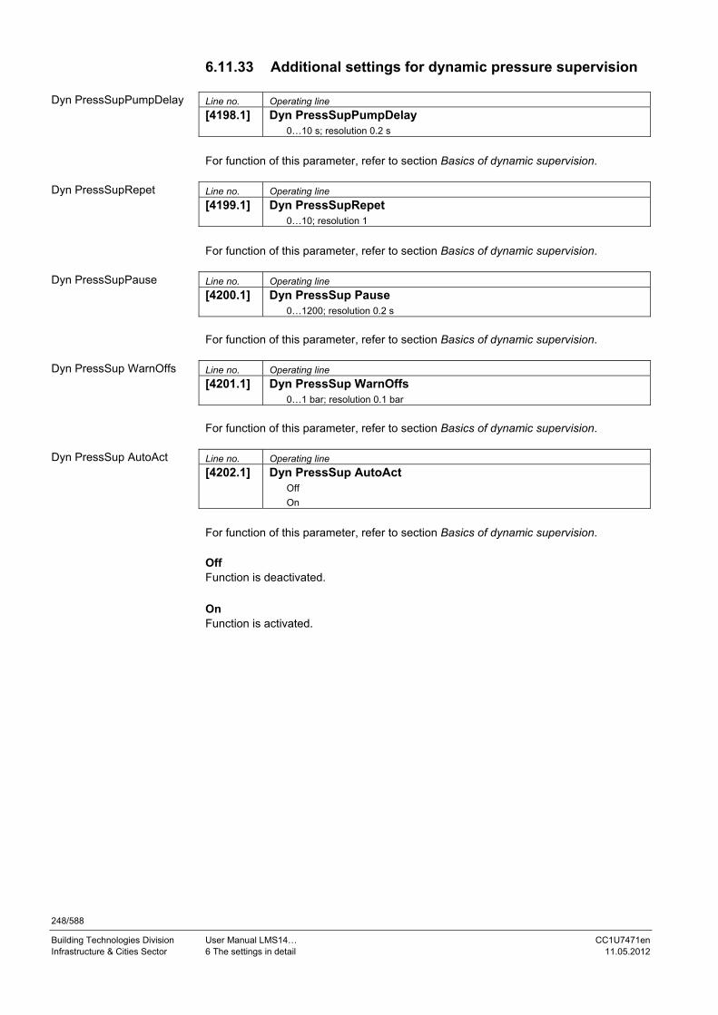
248/588
Building Technologies Division User Manual LMS14… CC1U7471en Infrastructure & Cities Sector 6 The settings in detail 11.05.2012
6.11.33 Additional settings for dynamic pressure supervision Line no. Operating line
[4198.1] Dyn PressSupPumpDelay 0…10 s; resolution 0.2 s
For function of this parameter, refer to section Basics of dynamic supervision. Line no. Operating line
[4199.1] Dyn PressSupRepet 0…10; resolution 1
For function of this parameter, refer to section Basics of dynamic supervision. Line no. Operating line
[4200.1] Dyn PressSup Pause 0…1200; resolution 0.2 s
For function of this parameter, refer to section Basics of dynamic supervision. Line no. Operating line
[4201.1] Dyn PressSup WarnOffs 0…1 bar; resolution 0.1 bar
For function of this parameter, refer to section Basics of dynamic supervision. Line no. Operating line
[4202.1] Dyn PressSup AutoAct Off
On
For function of this parameter, refer to section Basics of dynamic supervision. Off Function is deactivated. On Function is activated.
Dyn PressSupPumpDelay
Dyn PressSupRepet
Dyn PressSupPause
Dyn PressSup WarnOffs
Dyn PressSup AutoAct

249/588
Building Technologies Division User Manual LMS14… CC1U7471en Infrastructure & Cities Sector 6 The settings in detail 11.05.2012
6.12 Special boiler functions
6.12.1 Change of operating mode When there is a change between space heating and DHW heating, the controller responds as follows: DHW heating is ended and, at the same time, there is a request from space
heating: The controller switches the burner off. DHW overrun is performed while the position of the DHW controlling element is maintained
The request from space heating is overridden by a DHW request: The controller adopts the new DHW setpoint and makes use of the DHW thresholds. The DHW controlling element switches over to DHW heating. The controller switches off the burner only if the DHW switch-off threshold is or will be exceeded when changing from heating circuit to DHW operation mode. In general, however, the DHW setpoint lies above the setpoint for the heating circuit so that shutdown will not take place
6.12.2 Loading the setpoint/actual value Depending on the operating mode, the respective setpoints/actual values are loaded to the LMS14....
Heating mode DHW storage tank charging
Instantaneous water heating
Setpoint Boiler temperature setpoint
Boiler temperature setpoint/DHW charging setpoint
TwwSoll
Actual value Actual value of boiler temperature
Actual value of boiler temperature/ DHW charging temperature
TwwIst1/TRueck/ actual value of boiler temperature
Key
Line no. Meaning
TwwIst1 Sensor B38 at outlet of instantaneous water heater
TwwSoll Setpoint DHW outlet/keep hot setpoint
TRueck Boiler return temperature
In the case of instantaneous water heaters, the DHW setpoint is used. Depending on the configured type of instantaneous water heater, the respective actual value is loaded. With instantaneous water heaters, this is dependent on the type of hydraulic system, Outlet or Comfort mode and parameterization.

250/588
Building Technologies Division User Manual LMS14… CC1U7471en Infrastructure & Cities Sector 6 The settings in detail 11.05.2012
6.12.3 Automatic heat generation lock This function can be activated by the buffer storage tank (sensor B4/B41). The boiler is locked by the automatic heat generation lock when all valid requests for heat can be satisfied by the buffer storage tank and when the respective heat consumers are hydraulically connected with the buffer storage tank. Requests for heat from heat consumers not hydraulically connected with the buffer storage tank lead to a release of the boiler, even if the buffer storage tank holds sufficient amounts of heat. Each consumer segment can have its own buffer storage tank. Hence, the automatic heat generation lock can be parameterized per segment (refer to chapter Buffer storage tank). If the boiler is disabled by automatic heat generation lock while the burner is running, the burner is shut down, either immediately or only when the set minimum boiler temperature is reached, depending on the parameterization.
6.12.4 Manual heat generation lock An active manual heat generation lock disables the boiler, independent of current requests for heat. When there is an external request for heat, manual heat generation lock does not disable the boiler. For that purpose, one of the input contacts Hx, which can be parameterized, can be used. Protective boiler startup in progress with a boiler switch-off point at the minimum
boiler temperature is completed Maintained boiler return temperature acting on the consumers and shifting DHW
priority is aborted Boiler pump is deactivated on completion of the overrun time Frost protection for the boiler continues to be active When setting the parameters, the Heat generation lock function must be selected for the respective input Hx. The type of contact can be parameterized also (NC or NO). With certain hydraulic configurations, it may be necessary to exclude the boiler pump from the Locking function when the heat generation lock is active. This applies particularly to configurations where a buffer storage tank is available as a heat source. In that case, parameter Boiler pump on heat gen lock (2301) must be set to On.

251/588
Building Technologies Division User Manual LMS14… CC1U7471en Infrastructure & Cities Sector 6 The settings in detail 11.05.2012
6.12.5 Generation of common flow temperature setpoint The controller collects all valid heat requests from the consumers (heating circuits 1...3, DHW, instantaneous water heater, external requests 1...3) and classifies them according to their priorities. A maximum selection is made between requests for heat received from the heating circuits and external requests, which means that the highest temperature value called for becomes the common flow temperature setpoint. Requests for heat from DHW heating equipment are always given priority over other requests, thus enabling them to also let a temperature value lower than that demanded by the heating circuit and external consumers become the common flow temperature setpoint.
6.12.6 Generation of boiler temperature setpoint The boiler temperature setpoint represents the basis for control of the burner and is primarily dependent on the common flow temperature setpoint. If no request for heat from the consumers is active, there is also no valid setpoint. For the switch-on threshold in Standby mode, the temperature of parameter Setpoint frost protection (2217) is used. Whenever the burner is put into operation because there is a request for heat from the consumers, or because of the Frost protection function, the boiler temperature setpoint is limited downward to at least the adjusted minimum boiler temperature. A number of other functions can also influence the boiler temperature setpoint, either permanently or temporarily (functions Manual control, Chimney sweep, or Heat generation lock).
20 10 0 -10 -20 -30
40
30
60
50
80
70
90
TK
8744
T
8774
8704
w
20
°C
747
1d
05
/09
10
Figure 51: Generation of boiler temperature setpoint
Key
Line no. Meaning
8704 TAgem Composite outside temperature
8744 TVw Flow temperature setpoint of HC 1 (including setpoint increase, if any)
8774 TVw Flow temperature setpoint of HC 2 (including setpoint increase, if any)
TKw Boiler temperature setpoint

252/588
Building Technologies Division User Manual LMS14… CC1U7471en Infrastructure & Cities Sector 6 The settings in detail 11.05.2012
6.12.7 Boiler control Boiler control comprises all functions that translate a request (boiler temperature setpoint) to an output signal (control of burner as a percentage). Such functions include: Frost protection for the boiler 2-position control Modulating control Limitation and output of manipulated variable Chimney sweep Controller stop Manual control The boiler loop is in the form of a single temperature control loop.
Tsoll TIstP
KKPWMT
StreckeTT
K K StreckeP v
n
Boilersetpoint
Pneumatical /electricalratio
Adjustment ofmanipulatedvariable
Setpoint preselection Controller
K Sensor Sensor
Figure 52: Boiler control – modulating control
Key
Line no. Meaning
KFühler Sensor characteristic
KP Controller gain 1/XP
KPWM Conversion factor for positioning signal
KStell Fan characteristic
KStrecke Gain of controlled system
TStrecke Temperature of controlled system
P Pressure
PWM Fan control
TFühler Temperature acquired by sensor
TIst Actual value of temperature
Tn Integral action time
Tsoll Temperature setpoint
Tv Derivative action time
Modulating control

253/588
Building Technologies Division User Manual LMS14… CC1U7471en Infrastructure & Cities Sector 6 The settings in detail 11.05.2012
In the boiler loop, the temperature is controlled to the preselected setpoint. The boiler is used to supply heat to the heating circuits, the DHW heating equipment and the storage tanks. In DHW mode, a separate group of controller parameters are provided since a quick response is required should the tap be opened. The PID control algorithm calculates the required manipulated variable based on the control deviation (T = temperature setpoint minus actual value) and the selected control parameter settings. Using the control parameters, the respective controller part can be activated/hidden or matched to the controlled system. The heat output called for by the PID controller is limited to the permissible output range. Due to the overriding 2-position controller, the aforementioned modulating control loop is released and adjusted to the respective preselected setpoint. The result obtained by the temperature controller is passed to the burner control as the preselected output in percent. In all situations, the limit thermostat overrides the temperature control loop. The limit thermostat shuts down the boiler should its cutout temperature (Cutout temp LT (2531)) be reached.
6.12.8 Heat output limits The burner control ascertains the fan speed at which the burner maintains the minimum output without loss of flame. The maximum burner output in Heating mode can be preset via parameter in the form of fan speed. With the following operating modes, the heat output is statically preselected, which means that the results obtained by the LMS14... are ignored, and a load value in accordance with the function is forwarded to the burner control. Function Required output Chimney sweep Low-fire/high-fire/maximum heating load Controller stop Controller stop output setpoint
6.12.9 2-position controller The 2-position controller generates the signal for switching the burner control on and off:
Startup = On at Actual value of boiler temperature < boiler temperature setpoint – switch-
on threshold
Shutdown = Off at Actual value of boiler temperature > boiler temperature setpoint + switch-
off threshold
The switching differentials are loaded depending on the type of compensation (DHW or heating circuit). In addition, the dynamic switch-off differential influences the value of the switch-off threshold (also refer to chapter Dynamic switching differentials).
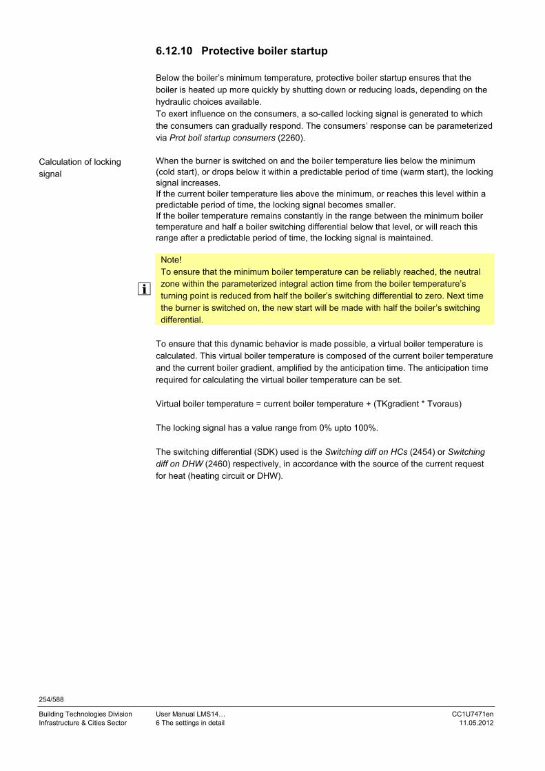
254/588
Building Technologies Division User Manual LMS14… CC1U7471en Infrastructure & Cities Sector 6 The settings in detail 11.05.2012
6.12.10 Protective boiler startup Below the boiler’s minimum temperature, protective boiler startup ensures that the boiler is heated up more quickly by shutting down or reducing loads, depending on the hydraulic choices available. To exert influence on the consumers, a so-called locking signal is generated to which the consumers can gradually respond. The consumers’ response can be parameterized via Prot boil startup consumers (2260). When the burner is switched on and the boiler temperature lies below the minimum (cold start), or drops below it within a predictable period of time (warm start), the locking signal increases. If the current boiler temperature lies above the minimum, or reaches this level within a predictable period of time, the locking signal becomes smaller. If the boiler temperature remains constantly in the range between the minimum boiler temperature and half a boiler switching differential below that level, or will reach this range after a predictable period of time, the locking signal is maintained.
Note! To ensure that the minimum boiler temperature can be reliably reached, the neutral zone within the parameterized integral action time from the boiler temperature’s turning point is reduced from half the boiler’s switching differential to zero. Next time the burner is switched on, the new start will be made with half the boiler’s switching differential.
To ensure that this dynamic behavior is made possible, a virtual boiler temperature is calculated. This virtual boiler temperature is composed of the current boiler temperature and the current boiler gradient, amplified by the anticipation time. The anticipation time required for calculating the virtual boiler temperature can be set. Virtual boiler temperature = current boiler temperature + (TKgradient * Tvoraus) The locking signal has a value range from 0% upto 100%. The switching differential (SDK) used is the Switching diff on HCs (2454) or Switching diff on DHW (2460) respectively, in accordance with the source of the current request for heat (heating circuit or DHW).
Calculation of locking signal

255/588
Building Technologies Division User Manual LMS14… CC1U7471en Infrastructure & Cities Sector 6 The settings in detail 11.05.2012
Graph for calculating the locking signal:
BZ 2210
-SDK/2
BR
BZ 8310
Minus
Temperature
Locking signal
Figure 53: Protective boiler startup – calculation of locking signal
Key
Line no. Meaning
2210 Setpoint minimum
8310 TKx Current boiler temperature
8310 TKIst Actual value of boiler temperature
BR Burner (0 = Off, 1 = On)
Minus Locking signal is decreased
Passiv Locking signal remains constant
Plus Locking signal is decreased
SDK Switching differential boiler
t Time
TKvirt Virtual boiler temperature
TKgradient Gradient of boiler temperature
Tvoraus Foreseeable time boiler temperature
Line no. Operating line
2260 Prot boil startup consumers 2264 Prot boil startup anticipation 2454 Switching diff on HCs 2460 Switching diff on DHW
Additional parameters

256/588
Building Technologies Division User Manual LMS14… CC1U7471en Infrastructure & Cities Sector 6 The settings in detail 11.05.2012
6.12.11 Keeping the boiler hot By parameterizing a minimum boiler temperature, lower setpoints called for by heat requests from the consumers are raised to this minimum boiler temperature. Whenever there is valid request for heat from the consumers, the boiler temperature is maintained at this minimum level. If there is no request for heat from the consumers, the boiler temperature is not always kept at the minimum level. If the boiler temperature drops below that minimum while the burner is Off, the burner is not started up. This functionality is not available for special hydraulic configurations. Hydraulic configurations with which the boiler pump is activated only if heating circuit 1 calls for heat cannot use the Keep hot function.
6.12.12 Alternative setting of output The speed settings (Fan speed heating max (2441), Fan speed full charging max (2442), Fan sp start value inst WH (2443), Fan speed DHW max (2444) and Controller delay speed (2452)) can be made in the form of speed values in min-1 (rpm) or load values in kW. The active setting is selected when generating the menu and is then defined for the unit on the online DD (EEPROM).

257/588
Building Technologies Division User Manual LMS14… CC1U7471en Infrastructure & Cities Sector 6 The settings in detail 11.05.2012
6.13 Cascaded systems
6.13.1 Addressing devices For configuration of the heat source cascade, the relevant address is the LPB device address: Device address = 0: No communication, standalone device. Device address = 1: Cascade master
Collects the requests for heat, controls the heat source sequence within the cascaded system, performs common functions (maintained return temperature, cascade lock, shifting DHW priority, etc.). Own heat source is integrated in the cascaded system like a cascade slave.
Device address = 2...16: Cascade slave
Controls own heat source based on information received from the cascade master.
All consumers (heating circuit, DHW, pumps H1/H2/H3) in the cascade master can still be used. In addition, consumers (heating circuit and pumps H1/H2/H3) can be used in the cascade slave. All requests for heat are forwarded to the cascade master (with the exception of HW separate circuit (5736)). Functions only used with device address 1 (buffer storage tank, system pump/primary controller) are only available with the cascade master.
Warning! In the case of instantaneous HW systems with Instant WH ctrl elem Q34 and DHW controlling element (5731) = Diverting valve, Basic position DHW div valve in connection with cascade applications must be set to Heating circuit, thus ensuring that the diverting valve is in the right position when there is a heat request from the cascade.
All parameters in connection with the cascade are to be set on the cascade master. Per LPB segment, one heat source cascade can be operated. Heat sources with the same segment address belong to the same cascade. If there is more than one cascade, none of them is allowed to be in segment 0.
Line no. Operating line
6600 LPB address
Additional parameters

258/588
Building Technologies Division User Manual LMS14… CC1U7471en Infrastructure & Cities Sector 6 The settings in detail 11.05.2012
6.13.2 Cascade master If there is more than one heat source, the device with device address 1 assumes the role of the cascade master. It activates the required functions and shows the additional menus with the parameters for use with the cascaded system. Identification of the master role can be effected automatically (Auto) or can be ready set (Always).
Device address
Parameters cascade master
Number of heat sources
State of cascade master
0 No cascade (zone)
0 1 (internally)
No cascade (individual boiler)
1 Auto 1 (internally or externally)
No cascade (individual boiler)
1 Auto > 1 (internally and
externally)
Cascade
1 Always 1 (internally or externally)
Cascade
1 Always >1 (internally and
externally)
Cascade
>1 1 (internally)
No cascade (cascade slave)
= can be any In a cascaded system, it is recommended to have the cascade master always running. This is to make certain that the cascade menus and common functions (e.g. common maintained return temperature) will not be lost if, for some reason, all heat sources except one are turned off.
Line no. Operating line
6630 Cascade master
Additional parameters

259/588
Building Technologies Division User Manual LMS14… CC1U7471en Infrastructure & Cities Sector 6 The settings in detail 11.05.2012
6.13.3 Operating mode
Line no. Operating line
3510 Lead strategy Late on, early off Late on, late off Early on, late off
Line no. Operating line
3511 Output band min
Line no. Operating line
3512 Output band max The heat sources are switched on and off according to the selected lead strategy while giving consideration to the preset output band. To deactivate the impact of the output band, the limit values must be set to 0% and 100%, and the lead strategy to be selected is Late on, late off. Late on, early off Additional boilers are switched on as late as possible (output band max) and switched off again as early as possible (output band max). This means that the smallest possible number of boilers are in operation, or additional boilers operate with short on times. Late on, late off Additional boilers are switched on as late as possible (output band max) and switched off again as late as possible (output band min). This leads to the smallest possible number of switch-on/off actions for the boilers. Early on, late off Additional boilers are switched on as early as possible (output band min) and switched off again as late as possible (output band min). This means that the largest possible number of boilers are in operation, or additional boilers operate with the longest possible on times.
Lead strategy
Output band min
Output band max

260/588
Building Technologies Division User Manual LMS14… CC1U7471en Infrastructure & Cities Sector 6 The settings in detail 11.05.2012
6.13.4 Control
Line no. Operating line
3530 Release integral source seq When, with the heat source currently in operation, the demand for heat cannot be met – the difference being the release integral set here – another boiler is switched on. When the value is increased, additional heat sources are switched on at a slower rate. When the value is decreased, additional heat sources are switched on at a faster rate.
Line no. Operating line
3531 Reset integral source seq When, with the heat source currently in operation, the demand for heat is exceeded by the reset integral set here, the heat source with the highest priority is shut down. When the value is increased, heat sources operate for longer periods of time (in the case of surplus heat). When the value is decreased, heat sources are switched off at a faster rate.
Line no. Operating line
3532 Restart lock The restart lock prevents a deactivated heat source from being switched on again. It is released again only after the set time has elapsed. This prevents too frequent switching actions of the heat sources and ensures stable plant operating states.
Line no. Operating line
3533 Switch on delay Correct adjustment of the switch-on delay ensures that plant operating conditions will be stable. This prevents too frequent switching actions of the boilers (cycling). In the case of a DHW request, the delay time is fixed at 1 minute.
Line no. Operating line
3534 Forced time basic stage When switched on, every boiler operates with its basic stage for the period of time set here. The next stage is released only when this period of time has elapsed.
Release integral cource seq
Reset integral source seq
Restart lock
Switch on delay
Forced time basic stage
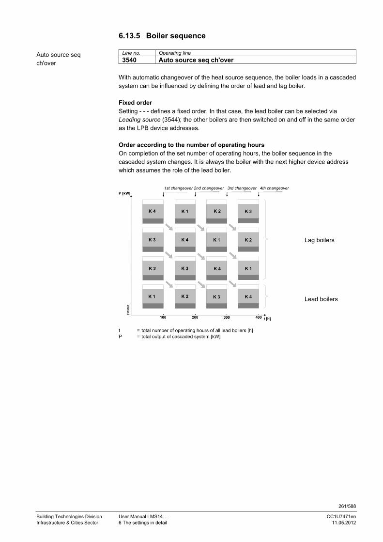
261/588
Building Technologies Division User Manual LMS14… CC1U7471en Infrastructure & Cities Sector 6 The settings in detail 11.05.2012
6.13.5 Boiler sequence
Line no. Operating line
3540 Auto source seq ch'over With automatic changeover of the heat source sequence, the boiler loads in a cascaded system can be influenced by defining the order of lead and lag boiler.
Fixed order
Setting - - - defines a fixed order. In that case, the lead boiler can be selected via Leading source (3544); the other boilers are then switched on and off in the same order as the LPB device addresses.
Order according to the number of operating hours
On completion of the set number of operating hours, the boiler sequence in the cascaded system changes. It is always the boiler with the next higher device address which assumes the role of the lead boiler.
1st changeover 2nd changeover 3rd changeover 4th changeover
K 1
K 2
K 3
K 4
K 2
K 3
K 4
K 1
K 3
K 4
K 1
K 2
K 4
K 1
K 2
K 3
t [h]100 300 400200
P [kW]
237
9Z07
Lag boilers
Lead boilers
t = total number of operating hours of all lead boilers [h] P = total output of cascaded system [kW]
Auto source seq ch'over

262/588
Building Technologies Division User Manual LMS14… CC1U7471en Infrastructure & Cities Sector 6 The settings in detail 11.05.2012
Line no. Operating line
3541 Auto source seq exclusion None First Last First and last
Setting Auto source seq exclusion is only used in connection with the activated heat source sequence (Auto source seq ch'over (3540)). When using Auto source seq exclusion, the first and/or the last boiler can be excluded from automatic changeover.
None
The order of switching on the boilers changes when the set number of operating hours are reached (Auto source seq ch'over (3540)).
First The first boiler in terms of addressing always remains the lead boiler. With the other boilers, the order of switching on changes when the set number of operating hours are reached (Auto source seq ch'over (3540)).
Last The last boiler in terms of addressing always remains the last. The other boilers change when the set number of operating hours are reached (Auto source seq ch'over (3540)).
First and last The first boiler in terms of addressing always remains the lead boiler. The last boiler in terms of addressing always remains the last. The boilers in between change when the set number of operating hours are reached (Auto source seq ch'over (3540)).
Line no. Operating line
3544 Leading source Source 1 Source 2 Source 3 Source 4 Source 5 Source 6 Source 7 Source 8 Source 9 Source 10 Source 11 Source 12 Source 13 Source 14 Source 15 Source 16
The leading heat source is only selected in connection with the fixed order of the heat source sequence (Auto source seq ch'over (3540)). The boiler selected as the lead boiler is always the first to be switched on, or the last to be switched off. The other boilers are switched on and off in the order of their device addresses.
Auto source seq exclusion
Leading source

263/588
Building Technologies Division User Manual LMS14… CC1U7471en Infrastructure & Cities Sector 6 The settings in detail 11.05.2012
6.13.6 Minimum limitation of return temperature
Line no. Operating line
3560 Return setpoint min If the return temperature drops below the adjusted setpoint, maintained boiler return temperature becomes active. The maintained boiler return temperature allows consumers to be influenced or a return temperature controller to be used.
Line no. Operating line
3561 Return setpoint min OEM Minimum limitation of the cascade return temperature (Return setpoint min (3560)) can be adjusted by the OEM. In that case, the person using the Heating engineer level can no longer set the minimum limitation of the cascade return temperature below the minimum value required for the boiler.
Line no. Operating line
3562 Return influence consumers Off On
If, with the boilers released, the cascade return temperature drops below the minimum temperature, a locking signal is calculated.
In the case of pump circuits, the consumer pumps (heating circuit pump, DHW charging pump, ext. load) are or will stay deactivated if the locking signal exceeds the respective threshold value
In the case of mixing circuits, the flow temperature setpoint is reduced according to the locking signal value
Return setpoint min
Return setpoint min OEM
Return influence consumers

264/588
Building Technologies Division User Manual LMS14… CC1U7471en Infrastructure & Cities Sector 6 The settings in detail 11.05.2012
6.13.7 Supervision of temperature differential
Line no. Operating line
3590 Temp differential min This function prevents excessive cascade return temperatures and improves the system’s switch-off behavior.
If the temperature differential between sensor B10 and sensor B70 becomes smaller than the set minimum temperature differential (Temp differential min (3590), one of the heat sources is switched off as early as possible, independent of the selected lead strategy. When the temperature differential is sufficiently great again, the selected lead strategy is resumed.
TB10
T
B70
7471z115/1009
Note! Switching off due to the minimum temperature differential does not apply to the last heat source in the cascaded system.
6.14 Extra heat source The extra heat source is activated by configuring one of the Qx outputs to Heat request K27.
Line no. Operating line
3690 Setpoint incr main source For the period of time the extra heat source is released, the setpoint of the main heat source is increased by the value set here. This prevents the main heat source from reducing its level of modulation. So the output of the main heat source is not reduced due to the additional output delivered by the extra heat source.
Temp differential min
Setpoint incr main source

265/588
Building Technologies Division User Manual LMS14… CC1U7471en Infrastructure & Cities Sector 6 The settings in detail 11.05.2012
6.15 Solar
6.15.1 General The basic unit supports solar DHW heating or heating backup via a buffer storage tank. Solar charging is performed with a single-speed charging pump on the basis of the temperature differential between DHW storage tank and collector, or between buffer storage tank and collector. The LMS14… supports: One collector panel with sensor B6 Collector pump Q5 (1-speed) One heat exchanger with sensor B3 or B31 One heat exchanger with sensor B4 or B41 The following functions are available: dT control of DHW storage tank and buffer storage tank Minimum and maximum charging temperature Minimum running time Pump and valve kick Status display (operating state) Overtemperature protection for the collector Storage tank recooling via the collector Storage tank recooling via the boiler/space heating Frost protection for the collector Evaporation of collector medium (protection for the pump) Collector start Collector hours run Display of minimum and maximum collector temperature
Note! A sensor B6 and collector pump Q5 must be parameterized at the multifunctional inputs/outputs (BX, QX) for configuration of the solar diagram and for the associated parameters to be displayed, or else the Solar DHW application must be used via an extension module.

266/588
Building Technologies Division User Manual LMS14… CC1U7471en Infrastructure & Cities Sector 6 The settings in detail 11.05.2012
6.15.2 Sensors
Sensor selection for the DHW storage tank
In addition to sensor B6, sensor B31 at the bottom is used for solar charging control. If that sensor is not available, sensor B3 at the top is automatically used. If both storage tank sensors are not available and the solar diagram is active, an error message is delivered and the collector pump deactivated, irrespective of collector temperature.
Sensor connected to ... Sensors used for solar charging control
B3 B31
-- -- Solar DHW heating not possible
Sensors Sensor B6 collector temperature Sensor B31 at the bottom storage tank temperature
Sensors -- Sensor B6 collector temperature Sensor B3 at the top storage tank temperature
-- no sensor connected with or without sensor or thermostat)
Note! If both storage tank sensors are not available (short-circuit or interruption), the collector pump is deactivated. If the collector sensor is not available (short-circuit or interruption), the collector pump is switched off also. In both cases, an error message is displayed.
Sensor selection for the buffer storage tank
In addition to sensor B6, sensor B41 at the bottom is used for solar charging control. If that sensor is not available, sensor B4 at the top is automatically used. If both storage tank sensors are not available and the solar diagram is active, an error message is delivered and the collector pump deactivated, irrespective of collector temperature.
Sensor connected to ...
Sensors used for solar charging control
B4 B41
-- -- Solar buffer storage tank charging not possible
Sensors Sensor B6 collector temperature Sensor B41 at the bottom storage tank temperature
Sensors -- Sensor B6 collector temperature Sensor B4 at the top storage tank temperature
-- no sensor connected with or without sensor
Note! If both storage tank sensors are not available (short-circuit or interruption), the collector pump is deactivated. If the collector sensor is not available (short-circuit or interruption), the collector pump is switched off as well. In both cases, an error message is displayed.

267/588
Building Technologies Division User Manual LMS14… CC1U7471en Infrastructure & Cities Sector 6 The settings in detail 11.05.2012
The swimming pool sensor is always sensor B13. If the solar plant is activated and the collector sensor or swimming pool sensor is not available (short-circuit or interruption), the collector pump is switched off and an error message appears.
Display of actual values
The temperatures acquired by sensor B6, B3 and B31 are displayed as collector temperature 1, DHW temperature 1, and DHW temperature 2. The temperature values of sensor B4 and B41 are displayed as Buffer storage tank temperature 1 and Buffer storage tank temperature 2. The swimming pool temperature acquired by sensor B13 is displayed as the Swimming pool temperature.
Line no. Operating line
8510 Collector temp 1 8830 DHW temp 1 8980 Buffer temp 1 8982 Buffer temp 2
Display of minimum and maximum values
Collector temperature (sensor B6) features a Slave pointer function displayed as Collector temperature 1 max and Collector temperature 1 min. They show the maximum and minimum collector temperatures reached. When making a reset, the values are reset to the current collector temperature.
Line no. Operating line
8511 Collector temp 1 max 8512 Collector temp 1 min
Collector sensor measured value correction
Readjustm collector sensor (6098) makes it possible to correct the temperature acquired by sensor B6 by ±20 K. The correction is linear across the entire measuring range.
Note! The temperature value of the Sensor temperature BX input test displays the uncorrected measured value. The logical temperature value Collector temperature 1 displays the corrected measured value used by the control system.
Line no. Operating line
6098 Readjustm collector sensor 8510 Collector temp 1
Sensor for the swimming pool
Additional parameters
Additional parameters
Additional parameters

268/588
Building Technologies Division User Manual LMS14… CC1U7471en Infrastructure & Cities Sector 6 The settings in detail 11.05.2012
6.15.3 Charging controller (dT)
Line no. Operating line
3810 Temp diff on
Line no. Operating line
3811 Temp diff off
Line no. Operating line
3812 Charg temp min DHW st tank
Line no. Operating line
3813 Temp diff on buffer
Line no. Operating line
3814 Temp diff off buffer
Line no. Operating line
3816 Temp diff on swi pool
Line no. Operating line
3817 Temp diff off swi pool
Line no. Operating line
3818 Charging temp min swi pool
Note! When using setting - - -, the general temperature differential solar (Temp diff on (3810) and Temp diff off (3811)) is adopted.
When charging the storage tank via the heat exchanger, the temperature differential between collector and storage tank/swimming pool must be sufficient, and the collector must have reached the minimum charging temperature for the storage tank/swimming pool.
Figure 54: Charging controller – charging temperature minimum swimming pool
Key
Meaning
On/Off Collector pump
SdAus Dynamic switch-off threshold
SdEin Switch-on threshold (heating circuit/DHW)
TKol Collector temperature
TLmin Minimum charging temperature DHW storage tank/buffer/swimming pool
TSp Storage tank temperature
Temp diff on
Temp diff off
Charg temp min DHW st tank
Temp diff on buffer
Temp diff off buffer
Temp diff on swi pool
Temp diff off swi pool
Charging temp min swi pool

269/588
Building Technologies Division User Manual LMS14… CC1U7471en Infrastructure & Cities Sector 6 The settings in detail 11.05.2012
Line no. Operating line
3815 Charging temp min buffer This function is used to activate the collector pump only when the collector temperature reaches a certain minimum level. In addition, the required temperature differential to the storage tank must be reached.
Note! If the function is deactivated, the collector pump is switched on whenever the required temperature differential to the storage tank is reached.
If the collector temperature lies below the minimum charging temperature, charging is aborted (even if the temperature differential still exists): Collector temperature < minimum collector temperature. If the collector temperature exceeds the minimum charging temperature by the switching differential (switch-on threshold – switch-off threshold) and the required temperature differential exists, charging can take place: Collector temperature > minimum collector temperature + (switch-on threshold – switch-off threshold).
T
t
Q5 offon on
B6
SDon - SDoffTSpMin
7471d20/1009 Figure 55: Charging controller – charging temperature minimum buffer
Key
Meaning
T Temperature
B6 Collector sensor
TSpMin Minimum storage tank temperature
SDon Switching differential On
SDoff Switching differential Off
Q5 Collector pump (On/Off)
t Time
Charging temp min buffer

270/588
Building Technologies Division User Manual LMS14… CC1U7471en Infrastructure & Cities Sector 6 The settings in detail 11.05.2012
6.15.4 Maximum charging temperature, maximum safety temperature
The storage tank is charged with solar energy up to the set Charging temp max at sensor B31/B41. If sensor B31/B41 is not available, sensor B3/B4 is used. Charging is aborted (storage tank temperature > maximum storage tank temperature) whenever the charging temperature in the storage tank is exceeded. Charging is released again (storage tank temperature < storage tank temperature – 1 K) when the storage tank temperature drops 1 K below the maximum charging temperature.
Caution! Function Protective collector overtemperature can reactivate the collector pump until the maximum storage tank temperature is reached.
Note! When using 2 sensors (B3 + B31 or B4 + B41), charging is aborted whenever one of the temperatures acquired by the 2 sensors lies above the maximum charging temperature.
1°C
T
t
B31 / B3
On
OffQ5
7471d21e/0111
Maximum charging temperature (2055/4750/5050)
Figure 56: Maximum charging temperature, maximum safety temperature
Key Meaning
B31/B3 DHW storage tank sensors
B41/B4 Buffer sensors
Q5 Collector pump (On/Off)
t Time
T Temperature
TSp Storage tank temperature
Note! Since the swimming pool temperature setpoint (Setpoint solar heating (2055)) equals the maximum charging temperature, the swimming pool is always charged until this temperature level is reached.
Line no. Operating line
4750 Charging temp max 4751 Storage tank temp max 2055 Setpoint solar heating 2070 Swimming pool temp max 5050 Charging temp max 5051 Storage tank temp max
Additional parameters

271/588
Building Technologies Division User Manual LMS14… CC1U7471en Infrastructure & Cities Sector 6 The settings in detail 11.05.2012
6.15.5 Priority
Note! The priority circuit for the swimming pool (Charging priority solar (2065)) can impact the storage tank priority of solar charging and possibly charge the swimming pool before the storage tanks are charged.
Line no. Operating line
3822 Charging prio storage tank None DHW storage tank Buffer storage tank
If a plant uses several heat exchangers, it is possible to set a priority for the integrated storage tanks, which defines the charging sequence. None Every storage tank is charged alternately by 5 °C at a time, until every setpoint of level A, B or C (see below) is reached. The setpoints of the next higher level are approached only when all setpoints of the previous level have been reached. DHW storage tank During solar charging, preference is given to the DHW storage tank. At every level A, B or C (see below), the storage tank is charged with priority. Only then will the other consumers of the same level be charged. As soon as all setpoints of a level are attained, those of the next level are approached, whereby priority is again given to the DHW storage tank. Buffer storage tank During solar charging, preference is given to the buffer storage tank. At every level A, B or C (see below), the storage tank is charged with priority. Only then will the other consumers of the same level be charged. As soon as all setpoints of a level are attained, those of the next level are approached, whereby priority is again given to the buffer storage tank. Storage tank setpoints:
Level DHW storage tank Buffer storage tank Swimming pool (¹)
A Nominal setpoint (1610) Buffer setpoint (slave pointer) Setpoint solar
heating (2055)
B Charging temp max (5050) Charging temp max (4750) Setpoint solar
heating (2055)
C Storage tank temp max
(5051)
Storage tank temp max (4751) Swimming pool temp
max (2070)
(¹) When priority for the swimming pool is activated (Charging priority solar (2065)), the swimming
pool is charged before the storage tanks are charged
Charging prio storage tank

272/588
Building Technologies Division User Manual LMS14… CC1U7471en Infrastructure & Cities Sector 6 The settings in detail 11.05.2012
Line no. Operating line
3825 Charging time relative prio If the preferred storage tank cannot be charged in accordance with charging control, priority is transferred to the next storage tank or the swimming pool for the set period of time (e.g. too great temperature differential between collector and storage tank). As soon as the preferred storage tank (according to setting Charging priority storage tank) is again ready to be charged, the transfer of priority is immediately stopped. If this parameter is disabled (---), charging proceeds in accordance with the Charging prio storage tank settings.
Line no. Operating line
3826 Waiting time relative prio During the set time, the transfer of priority is delayed. This prevents relative priority from intervening too frequently.
Line no. Operating line
3827 Waiting time parallel op If solar output is sufficient and solar charging pumps are used, parallel operation is possible. In that case, the storage tank of the priority model can be the next to be simultaneously charged, in addition to the storage tank to be charged next. Parallel operation can be delayed by introducing a waiting time. This way, in the case of parallel operation, switching on of the storage tanks can be effected in steps. Setting (---) disables parallel operation.
Line no. Operating line
3828 Delay secondary pump To carry away any cold water resting in the primary circuit, the secondary pump of the external heat exchanger can be delayed.
Charging time relative prio
Waiting time relative prio
Waiting time parallel op
Delay secondary pump

273/588
Building Technologies Division User Manual LMS14… CC1U7471en Infrastructure & Cities Sector 6 The settings in detail 11.05.2012
6.15.6 Collector start function
Line no. Operating line
3830 Collector start function If the collector temperature cannot be correctly acquired because the pump is not running (especially in the case of vacuum tubes), the pump can be activated from time to time. The function activates the collector pump at the set interval for at least the parameterized minimum running time. If the required collector temperature is reached within the minimum running time, the pump keeps running. If the collector temperature does not reach the required level, the pump is deactivated again.
Note! The Collector start function is only performed if the storage tank temperature does not lie above the storage tank safety temperature.
Line no. Operating line
3831 Min run time collector pump When the collector pump is activated, it operates for the minimum running time, independent of temperature differentials. The minimum running time of the pump can be parameterized and is active with all functions that activate the collector pump.
F
OnQ5
Active
tmin
t7471d22e/1009
Figure 57: Collector start function – minimum run time collector pump
Key
Meaning
F Function (Active/Inactive)
Q5 Collector pump (On/Off)
tmin Minimum collector pump running time
t Time
Line no. Operating line
3832 Collector start function on The Collector start function starts at the time of day set here.
Line no. Operating line
3833 Collector start function off The Collector start function ends at the time of day set here.
Collector start function
Min run time collector pump
Collector start function on
Collector start function off

274/588
Building Technologies Division User Manual LMS14… CC1U7471en Infrastructure & Cities Sector 6 The settings in detail 11.05.2012
Line no. Operating line
3834 Collector start funct grad The collector pump is activated whenever the temperature acquired by the collector sensor rises. To ensure that the flow pipe from the collector to the storage tank also receives hotter water, deactivation of the collector pump after reaching the frost protection threshold at the collector sensor is delayed by the minimum running time.
FS
OnQ5
Active
tmin
t7471d23e/1009 Figure 58: Collector start function – special case frost protection
Key
Meaning
F Function (Active/Inactive)
Q5 Collector pump (On/Off)
tmin Minimum collector pump running time
t Time
Collector start funct grad
Special case: Frost protection

275/588
Building Technologies Division User Manual LMS14… CC1U7471en Infrastructure & Cities Sector 6 The settings in detail 11.05.2012
6.15.7 Frost protection for the collector
Line no. Operating line
3840 Collector frost protection When there is risk of frost at the collector, the collector pump is activated to prevent the heat-carrying medium from freezing. If the collector temperature falls below the frost protection temperature, the
collector pump is activated: Collector temperature < frost protection collector temperature
When the collector temperature returns to a level of 1 K above the frost protection temperature, the collector pump is deactivated again: Collector temperature > frost protection collector temperature + 1
Note! No consideration is given to the temperature in the storage tank. In normal situations, the storage tank is discharged while the collector assumes a higher temperature.
T
t
1°CBZ 3840
B6
OnOff
Q5
7471d24e/1210 Figure 59: Frost protection for the collector
Key
Line no. Meaning
3840 TKolFrost Frost protection collector temperature
B6 Temperature acquired by collector sensor
Q5 Collector pump (On/Off)
t Time
T Temperature
Collector frost protection

276/588
Building Technologies Division User Manual LMS14… CC1U7471en Infrastructure & Cities Sector 6 The settings in detail 11.05.2012
6.15.8 Overtemperture protection for the collector
Line no. Operating line
3850 Collector overtemp prot If there is a risk of overtemperature at the collector, storage tank charging is continued to reduce the amount of surplus heat. When the maximum storage tank temperature is reached, charging is stopped. If the collector temperature exceeds the temperature level of Overtemperature protection for the collector, and if the maximum storage tank temperature is not yet reached, the collector pump is activated (collector temperature > overtemperature protection for the collector and storage tank temperature < maximum storage tank temperature). If the collector temperature drops by the switching differential below the temperature level of Overtemperature protection for the collector, the collector pump is deactivated again (collector temperature < overtemperature protection for the collector – switching differential overtemperature). If the storage tank temperature increases to the maximum storage tank temperature, the collector pump is deactivated (storage tank temperature > maximum storage tank temperature). If the storage tank temperature drops 1 K below the tank’s safety temperature, the collector pump is activated again (storage tank temperature < maximum storage tank temperature – 1).
Tkol
3850
1°C
1°C
T
t
TSp
On
Off
Maximum storage tank temperature(4751/5051/2070)
Figure 60: Overtemperature protection for the collector
Key Line no. Meaning
3850 TKolUe Overtemperature protection for collector
2070 Maximum storage tank temperature (buffer/DHW/swimming pool)
4751 Maximum storage tank temperature (buffer/DHW/swimming pool)
5051 Maximum storage tank temperature (buffer/DHW/swimming pool)
On/Off Collector pump
SdUe Switching differential overtemperature (fixed at 5 K)
t Time
T Temperature
TKol Collector temperature
TSp Storage tank temperature
Collector overtemp prot

277/588
Building Technologies Division User Manual LMS14… CC1U7471en Infrastructure & Cities Sector 6 The settings in detail 11.05.2012
Note! If 2 storage tank sensors are used, the sensor acquiring the higher temperature is considered.
Caution! The collector pump is deactivated if one of the storage tank temperatures is not available (short-circuit or interruption).
Line no. Operating line
2070 Swimming pool temp max 3850 Collector overtemp prot Menu: Buffer storage tank 4751 Storage tank temp max (buffer storage tank) Menu: DHW storage tank 5051 Storage tank temp max (DHW storage tank)
Additional parameters

278/588
Building Technologies Division User Manual LMS14… CC1U7471en Infrastructure & Cities Sector 6 The settings in detail 11.05.2012
6.15.9 Recooling It makes sense to use recooling together with overtemperature protection. If the DHW storage tank has already reached the maximum storage tank temperature level, which means that overtemperature protection for the collector is no longer possible, recooling can again lower the storage tank’s temperature level (typically during the night). Recooling of the storage tank can be accomplished via the collector’s surface or the heat source and space heating.
Note! Cooling mode is canceled if the DHW storage tank must be recooled during Cooling mode.
The surplus energy held by the storage tank can be released to the environment by circulating the water through the cold collector. The collector pump is activated if the lower storage tank temperature at sensor B31/B41 is at least 2 K above the recooling setpoint and higher than the collector temperature by at least the parameterized charging switching differential. (Storage tank temperature > recooling temperature + 2 K and storage tank temperature > collector temperature + switching difference). The collector pump is switched off if the collector temperature comes within 2 K of the storage tank temperature (collector temperature > storage tank temperature – 2 K) The function is ended if the recooling temperature within 1 K of the room temperature setpoint for cooling (Storage tank temperature < recooling temperature + 1 K) The function can be deactivated. In addition, it is possible to select whether it should be active throughout the year or only in the summer.
T
t
Q5
SDRü
B6
B3/B31
Off On Off On
TRKw
2°C
Off
B4/B41
7471d25e/1210
Figure 61: Recooling – recooling via the collector's surfaces
Key Line no. Meaning
B3/B31 DHW storage tank sensors
B4/B41 Buffer sensors
B6 Collector sensor
Q5 Collector pump (On/Off)
t Time
T Temperature
SdRü Switching differential for recooling
TRKW Recooling temperature
Recooling via the collector’s surface

279/588
Building Technologies Division User Manual LMS14… CC1U7471en Infrastructure & Cities Sector 6 The settings in detail 11.05.2012
Note! The switching differential for recooling (SdRü) corresponds to the value of the switch-on differential (SdEin) of the charging controller, but is limited for recooling to a minimum of 3 °C. The function is performed with sensor B3/B4 if sensor B31/B41 at the bottom is not connected. The function is not available if there are no storage tank sensors.
Line no. Operating line Menu: DHW storage tank 5024 Switching diff (DHW storage tank) 5055 Recooling temp (DHW storage tank) 5057 Recooling collector (DHW storage tank) Menu: Buffer storage tank 4755 Recooling temp (buffer storage tank) 4757 Recooling collector (buffer storage tank)
Surplus energy in the storage tank can be released to the environment via the heat source/cooling source and space heating. With this function, the heat in the storage tank is delivered to the heat source by means of charging pump Q3/source pump, the heating circuit pump is activated and the mixing valve opened.
Caution! To enable forced switching on of the heating circuits, the Recooling storage tank function must be activated (can be set for each heating circuit). Heating circuits that are already in operation draw more heat. If there is no sensor B3/B4, the function is not performed.
If the upper storage tank temperature at sensor B3/B4 lies 2 K above the recooling temperature and if the heat source temperature lies at least SdRü below the storage tank temperature, the DHW charging pump/source pump is activated (storage tank temperature > recooling temperature and storage tank temperature > heat source temperature + SdRü). If the storage tank temperature only lies by the switching differential above the heat source temperature, the DHW charging pump/source pump is deactivated (storage tank temperature > heat source temperature + switching differential). If the storage tank temperature falls below the recooling temperature, the function is ended (storage tank temperature < recooling temperature).
Line no. Operating line Menu: DHW storage tank 5024 Switching diff (DHW storage tank) 5055 Recooling temp (DHW storage tank) 5056 Recooling heat gen/HCs (DHW storage tank) Menu: Buffer storage tank 4755 Recooling temp (buffer storage tank) 4756 Recooling DHW/HCs (buffer storage tank)
Key
Line no. Meaning
SdRü Switching differential for recooling
Additional parameters
Recooling via heat source/cooling source/ space heating
Additional parameters

280/588
Building Technologies Division User Manual LMS14… CC1U7471en Infrastructure & Cities Sector 6 The settings in detail 11.05.2012
6.15.10 Evaporation temperature of medium
Line no. Operating line
3860 Evaporation heat carrier If there is a risk of evaporation of the heat conducting medium due to high collector temperatures, the collector pump is deactivated to prevent the medium from reaching excessive temperatures. This is a protective pump function. When, due to high collector temperatures, there is a risk of evaporation of the heat conducting medium, the collector pump is deactivated to prevent it from running hot. This is a protective pump function. If the collector temperature exceeds the evaporation temperature of the heat conducting medium (collector temperature > evaporation temperature), the collector pump is deactivated to prevent overtemperatures. If the collector temperature falls one switching differential (15 K) below the evaporation temperature, the collector pump is activated again (collector temperature < evaporation temperature – switching differential evaporation temperature). The function can be deactivated.
T
t
SdVerd
B6
Q5On
Off
3860
7471d26e/1210 Figure 62: Evaporation temperature of medium
Key
Line no. Meaning
3860 Tverd Evaporation temperature
B6 Collector sensor
Q5 Collector pump (On/Off)
SdVerd Switching differential evaporation temperature (15 K)
t Time
T Temperature
Caution! Evaporation protection for the medium (pump Off) is given priority over overtemperature protection, which wants to activate the pump.
Evaporation heat carrier

281/588
Building Technologies Division User Manual LMS14… CC1U7471en Infrastructure & Cities Sector 6 The settings in detail 11.05.2012
6.15.11 Speed control
Line no. Operating line
3865 Starting speed coll pump 1 Starting speed of the collector pump.
Line no. Operating line
3867 Starting speed exch pump Starting speed of the solar heat exchanger pump.
Line no. Operating line
3868 Starting speed buffer pump Starting speed of the solar buffer storage tank charging pump.
Line no. Operating line
3869 Starting speed swi pool pump Starting speed of the solar swimming pool charging pump.
Line no. Operating line
3870 Pump speed min 3871 Pump speed max
The speed of the solar pump motor is limited (minimum and maximum permissible speed).
Line no. Operating line
3872 Speed Xp 3873 Speed Tn
The charging setpoint for the storage tank with the first charging priority and the collector temperature are used for speed control. The PI controller calculates the speed such that the collector temperature lies 2 K below the switch-on temperature. If, due to strong solar radiation, the collector temperature rises, the speed is increased. If the collector temperature drops below this setpoint, the speed is decreased. A parameter is available to select minimum and maximum limitation of pump speed. The PI controller can be adjusted via parameters Proportional band (Xp) and Integral action time (Tn). It has a neutral zone of ±1 K. The resulting speed is delivered via P1 function output (PWM output) as configured. With charging priority changeover, the speed is controlled by the controller according to the new charging setpoint.
Line no. Operating line
3875 Pump speed min OEM 3876 Pump speed max OEM
These are the limits of the speed range for control of the solar pump at the OEM level. These limits confine the setting range at the Heating engineer level.
Starting speed coll pump 1
Starting speed exch pump
Starting speed buffer pump
Starting speed swi pool pump
Pump speed min/max
Speed Xp/Tn
Pump speed min/max OEM

282/588
Building Technologies Division User Manual LMS14… CC1U7471en Infrastructure & Cities Sector 6 The settings in detail 11.05.2012
6.15.12 Yield measurement The 24-hour and total solar energy yield (24-hour yield solar energy (8526) and Total yield solar energy (8527)) are calculated based on these data.
Line no. Operating line
3880 Antifreeze None Ethylene glycol Propylene glycol Ethyl and propyl glycol
Since the mixing ratio of the collector medium has an impact on heat transmission, the type of antifreeze used and its concentration must be entered, thus allowing calculation of the energy yield.
Line no. Operating line
3881 Antifreeze concentration Since the mixing ratio of the collector medium has an impact on heat transmission, the type of antifreeze used and its concentration must be entered, thus allowing calculation of the energy yield.
Line no. Operating line
3884 Pump capacity The pump’s flow rate in l/h must be determined and serves for calculating the volumetric flow.
Line no. Operating line
3887 Pulse unit yield Defines the flow rate per pulse for the selected input Hx. For that purpose, the respective input Hx must be configured for counting pulses.
6.15.13 Hours run The number of operating hours of the collector pump are added up by counters. Hours run solar yield only includes the periods of time during which heat is supplied from the collector to the storage tank. The Hours run collect overtemp is the sum of operating hours during which the Overtemperature protection function has been active.
Note! The hours run can be reset.
Line no. Operating line
8530 Hours run solar yield 8531 Hours run collect overtemp 8532 Hours run collector pump
Antifreeze
Antifreeze concentration
Pump capacity
Pulse unit yield
Additional parameters

283/588
Building Technologies Division User Manual LMS14… CC1U7471en Infrastructure & Cities Sector 6 The settings in detail 11.05.2012
6.16 Solid fuel boiler
6.16.1 General The basic unit permits straightforward dT control of an uncontrolled solid fuel boiler with boiler sensor, boiler pump and a selectable comparative temperature (DHW storage tank, buffer storage tank, flow temperature setpoint, minimum setpoint). The following functions are available: dT controller with selectable comparative temperature Minimum setpoint Locking another heat source Excess heat discharge Boiler pump overrun DHW charging priority Hours run counter Status display (operating state)
B22
Q10
T
7471d37/1009
When configuring the solid fuel boiler diagram, sensor B22 and solid fuel boiler pump Q10 must be parameterized at the multifunctional inputs/outputs (BX, QX). For the solid fuel boiler diagram to be activated and the associated parameters to be displayed, the boiler sensor must be connected.

284/588
Building Technologies Division User Manual LMS14… CC1U7471en Infrastructure & Cities Sector 6 The settings in detail 11.05.2012
6.16.2 Operating mode
Line no. Operating line
4102 Locks other heat sources Off On
When the solid fuel boiler is put into operation, other heat sources, such as oil/gas boilers, are locked. Locking takes place whenever the boiler temperature rises to such a level that crossing of the comparative temperature can be expected. This anticipation function enables the locked heat sources to end any pump overrun before the solid fuel boiler pump is activated. Also, in the case of a common stack, it can be made certain that only one boiler is in operation at a time.
Note! Due to locking of the other heat sources (Locks other heat sources (4102) set to On), an installed system pump is also locked when System pump on heat gen lock (2121) is set to Off. In that case, consumers downstream from the system pump do not receive any heat.
T
t
41334 K
10'
Stat
TKx
831010'
4 K
10
7471d36/0910
Figure 63: Operating mode
Key
Line no. Meaning
4133 TVgl Comparative temperature
8310 TKx Current boiler temperature
8560 TFx Solid fuel boiler temperature
10´ Actual value of boiler temperature anticipated in 10 minutes
dt Progression of time
dTF Temperature rise of solid fuel boiler
Stat State of heat generation lock (0 = not locked, 1 = locked)
Locks other heat sources

285/588
Building Technologies Division User Manual LMS14… CC1U7471en Infrastructure & Cities Sector 6 The settings in detail 11.05.2012
The heat generation lock is activated if – based on the current temperature rise – the boiler temperature will exceed the comparative temperature by 4 K in 10 minutes. Heat generation lock remains active for as long as the boiler pump is running. Active when: Temperature of solid fuel boiler + dTFx/dt *10’ > comparative temperature + 4 K or boiler pump Q10 = On The heat generation lock is deactivated if the boiler pump is switched off again (at the end of pump overrun), or if the boiler temperature does not exceed the required comparative temperature by more than 4 K in 10 minutes so that the boiler pump would not be switched on at all. The function can be activated/deactivated.
Note! The function is only active with device address 0 or 1.
Off Function is deactivated. On Function is activated.

286/588
Building Technologies Division User Manual LMS14… CC1U7471en Infrastructure & Cities Sector 6 The settings in detail 11.05.2012
6.16.3 Setpoints
Line no. Operating line
4110 Setpoint min The boiler pump is put into operation only when the boiler temperature reaches a minimum level, in addition to the required temperature differential.
T
4110
0
1Q10
8560
t7471d35/0910 Figure 64: Setpoints
Key
Line no. Meaning
4110 TFsMin Minimum setpoint
4130 SdTFEin Temperature differential On
4131 SdTFAus Temperature differential Off
8560 TFx Solid fuel boiler temperature
Q10 Solid fuel boiler pump
t Time
T Temperature
The boiler pump is deactivated if the boiler temperature lies below the minimum setpoint: Temperature of solid fuel boiler < temperature differential Off. The boiler pump is activated if the boiler temperature exceeds the minimum setpoint by the switching differential (temperature differential On – temperature differential Off): (Temperature of solid fuel boiler > minimum setpoint + (temperature differential On – temperature differential Off). The criterion of the minimum setpoint is always taken into account, which means that the function cannot be deactivated.
Note! If pump overrun is parameterized, the boiler pump will not be deactivated until the Pump overrun time (4140) has elapsed.
Line no. Operating line
4110 Setpoint min 4130 Temp diff on 4131 Temp diff off
Setpoint min
Additional parameters

287/588
Building Technologies Division User Manual LMS14… CC1U7471en Infrastructure & Cities Sector 6 The settings in detail 11.05.2012
6.16.4 Control of the boiler/burner For the boiler pump to be put into operation, a sufficiently great temperature differential between boiler temperature and comparative temperature is required.
Figure 65: Control of the boiler /burner – delta T controller
Key
Line no. Meaning
8310 TKx Boiler temperature
Bx Current comparative temperature
On/Off Boiler pump (On/Off)
QX Relay output
SDoff Switching differential Off
SDon Switching differential On
t Time
T Temperature
If the boiler temperature exceeds the comparative temperature by the switch-on differential, the boiler pump is activated: Current boiler temperature > comparative temperature + temperature differential On. If the boiler temperature drops by the switch-off differential below the comparative temperature, the boiler pump is deactivated: Current boiler temperature < comparative temperature + temperature differential Off. For the boiler pump to be activated, the boiler temperature must have reached not only the necessary temperature differential, but also Setpoint min (4110).
Note! If pump overrun is parameterized, the boiler pump will not be deactivated until the overrun time has elapsed.
Line no. Operating line
4130 Temp diff on Switch-on temperature differential for control of the solid fuel boiler.
Line no. Operating line
4131 Temp diff off Switch-off temperature differential for control of the solid fuel boiler.
Delta T-controller
Temp diff on
Temp diff off

288/588
Building Technologies Division User Manual LMS14… CC1U7471en Infrastructure & Cities Sector 6 The settings in detail 11.05.2012
Line no. Operating line
4133 Comparative temp DHW sensor B3 DHW sensor B31 Buffer sensor B4 Buffer sensor B41 Flow temp setpoint Setpoint min
The comparative temperature for generating the temperature differential to sensor B22 can be selected via parameter: DHW storage tank (sensor B3 or B31) Buffer storage tank (sensor B4 or B41) Flow temperature setpoint (common) Minimum setpoint (fixed value) The selection of the comparative temperature also defines the way the solid fuel boiler is integrated into the hydraulic system and the available choice of functions.
Note! If sensor B3, B31, B4, B41 or the flow temperature setpoint is used for the comparative temperature, it is also possible to parameterize the minimum setpoint for the pump’s switch-on criterion.
DHW storage tank
If sensor B3 or B31 is selected for the comparative temperature, this is the equivalent of integrating the solid fuel boiler directly into the DHW storage tank. Setpoint min (4110) is taken into account. With this kind of integration, DHW charging pump Q3 is only used for DHW heating with a heat source that has open-loop control and is not influenced by the temperature of the wood-fired boiler.
B22
Q10
B3
B31
Q3
B2
Q1
K4
T
7471d34/1009
T
T
T
Figure 66: Boiler/burner control – DHW storage tank
Note! Functions Excess heat discharge (forced signal to consumers) and Locks other heat sources are active and must be deactivated, if necessary (Locks other heat sources (4102), Excess heat discharge (4141)).
Comparative temp

289/588
Building Technologies Division User Manual LMS14… CC1U7471en Infrastructure & Cities Sector 6 The settings in detail 11.05.2012
Buffer storage tank
Sensor B4 or B41 is selected for the comparative temperature. Setpoint min (4110) is taken into account.
B22
Q10
B2
Q1
K4
B4
B41
T
7471d33/1009
T
T
T
Figure 67: Control of boiler/burner – buffer storage tank
Note! The function of a buffer storage tank is only available with LPB device address 0 or 1.
Flow temperature setpoint
The common flow temperature setpoint (request for heat from all consumers) is selected as the comparative temperature. Setpoint min (4110) is taken into account.
B22
Q10
TVSw
T
7471d32/1009
Key Line no. Meaning
TVSw Common flow temperature setpoint
Note! If there is no valid request for heat, Setpoint min (4110) applies. The function is only available with LPB device address 0 or 1.

290/588
Building Technologies Division User Manual LMS14… CC1U7471en Infrastructure & Cities Sector 6 The settings in detail 11.05.2012
Minimum setpoint
Setpoint min (4110) is selected as the comparative temperature. This means that activation of the boiler pump is solely dependent on the temperature of its boiler.
B22
Q10
4110
7471d31/1009

291/588
Building Technologies Division User Manual LMS14… CC1U7471en Infrastructure & Cities Sector 6 The settings in detail 11.05.2012
6.16.5 Overtemperature protection
Line no. Operating line
4140 Pump overrun time If the temperature of the solid fuel boiler drops below the minimum temperature differential or the minimum setpoint, the boiler pump remains activated for the parameterized overrun time. There is no pump overrun, if the pump was activated due to frost protection for the boiler, frost protection for the plant, or overtemperature.
Line no. Operating line
4141 Excess heat discharge If the boiler temperature reaches the set maximum value, excess heat discharge becomes active. This forces the connected consumers to draw heat from the solid fuel boiler. At the same time, the boiler pump is activated.
T
4141
0
1Q10 + ZS
5 K
8310
t7471d30/0910 Figure 68: Overtemperature protection
Key Line no. Meaning
4141 Excess heat discharge
8310 TKx Current boiler temperature
Q10 Solid fuel boiler pump
ZS Forced signal
Excess heat discharge is stopped when the boiler temperature lies 5 K below the set Excess heat discharge (4141). Using parameter Excess heat draw (e.g. (861) for heating circuit 1), it is possible to select for every consumer whether or not the forced signal shall be considered, thus deciding whether or not the consumer shall contribute to the dissipation of heat. The discharge of excess heat in the system always takes place segment by segment. System-wide distribution of excess heat discharge starting from segment 0 is not possible. The consumers give consideration to the forced signal only if demanded by parameter Excess heat draw (e.g. (861) for heating circuit 1).
Note! RVA... devices do not understand the forced signal and do not therefore take part in the discharge of heat.
Pump overrun time
Excess heat discharge

292/588
Building Technologies Division User Manual LMS14… CC1U7471en Infrastructure & Cities Sector 6 The settings in detail 11.05.2012
6.16.6 Frost protection
Line no. Operating line
4170 Frost prot plant boiler pump On Off
The boiler pump is activated, depending on the current outside temperature, although there is no request for heat.
Note! Frost protection for the solid fuel boiler works only if Frost protection plant (6120) for the plant is activated.
Outside temperature Boiler pump Graph
...-4 °C Continuously On ON -5...1.5 °C Every 6 hours On for 10 minutes Takt 1.5 °C... Continuously Off OFF
717
4z1
03e
/020
9
Figure 69: Frost protection
Off Function is deactivated. On Function is activated.
Frost prot plant boiler pump

293/588
Building Technologies Division User Manual LMS14… CC1U7471en Infrastructure & Cities Sector 6 The settings in detail 11.05.2012
6.16.7 Frost protection for the solid fuel boiler Function Frost protection for the boiler ensures that the pump of the solid fuel boiler is activated when the boiler temperature drops below its Frost protection level (4 °C). The function cannot be deactivated.
T
5°C
0
1Q10
4°C
8560
t7471d29/0910 Figure 70: Frost protection for the solid fuel boiler
Key Line no. Meaning
8560 TFx Solid fuel boiler temperature
Q10 Solid fuel boiler pump
t Time
T Temperature
6.16.8 Configuration errors A configuration error (error 146) is generated if sensor B22 is connected and boiler pump Q10 is not parameterized. A configuration error is generated if a solid fuel boiler diagram is active and DHW storage tank or Buffer storage tank is selected as the comparative temperature but the respective diagram is missing. A configuration error is generated if a solid fuel boiler diagram is active and Flow temperature setpoint is selected as the comparative temperature and the device address is >1. 6.16.9 Sensor error
Boiler sensor If sensor B22 is not available (short-circuit or interruption), an error message is generated and the boiler pump is forced to switch on.
Comparative sensor If the selected comparative sensor B3, B31, B4 or B41 is not available (short-circuit or interruption), the minimum setpoint set in the parameters is used for the calculation. No specific error message is generated when the comparative sensor is unavailable. An error message might be generated by the comparative sensor itself.

294/588
Building Technologies Division User Manual LMS14… CC1U7471en Infrastructure & Cities Sector 6 The settings in detail 11.05.2012
6.17 Buffer storage tank 6.17.1 Release/control of heat source Release/control of the heat source with a buffer storage tank is described in the following chapters: Oil- or gas-fired boiler: Chapter Automatic heat generation lock Solid fuel boiler: Chapter Solid fuel boiler
6.17.2 Automatic locks Automatic heat generation lock brings about a temporary hydraulic separation of heat source and buffer storage tank. The heat source is put into operation only when the buffer storage tank is no longer able to satisfy the current demand for heat.
Line no. Operating line
4720 Auto generation lock None
With B4
With B4 and B42/B41 None Function is deactivated. With B4 Sensor B4 is used to lock or release the heat source. With B4 and B42/B41 Sensor B4 is used to release the heat source. For the heat generation lock, sensor B42 is used, and if that sensor is not available, sensor B41.
Line no. Operating line
4721 Auto heat gen lock SD The switching differential is adjustable.
Auto generation lock
Auto heat gen lock SD

295/588
Building Technologies Division User Manual LMS14… CC1U7471en Infrastructure & Cities Sector 6 The settings in detail 11.05.2012
Line no. Operating line
4722 Temp diff buffer/HC If the temperature differential T between buffer storage tank and heat request from the heating circuit is sufficiently great, the amount of heat required by the heating circuit is drawn from the buffer storage tank. The heat source is locked.
Note! When using Temp diff buffer/HC (4722), the mixing valve boost of the heat request from the heating circuit can be compensated.
B4
E
1K
t
4722
Figure 71: Automatic locks
Key
Line no. Meaning
4722 Temperature differential of buffer and heating circuit
B4 Buffer sensor
E Heat generation lock
t Time
T Temperature
TVLw Flow temperature setpoint
Line no. Operating line
4724 Min st tank temp heat mode A minimum buffer storage tank temperature can be set in the parameters for heat consumers (mixing valves or pump circuits and heat consumers connected via H1/H2). If the heat source is malfunctioning or locked (or not present), the consumers can be switched off if the buffer storage tank is too cold. This function prevents heat consumers from letting their pumps run although no heat is available. The heat consumers are locked if the temperature at the warmest sensor in the buffer storage tank drops by more than 1 K below the minimum level and – at the same time – no heat source is available. The consumers are released again when the buffer storage tank temperature returns to the minimum level (or a heat source becomes available).
Note! Consumers that do not draw their heat from the buffer storage tank are not affected by this switching off action.
Temp diff buffer/HC
Min st tank temp heat mode

296/588
Building Technologies Division User Manual LMS14… CC1U7471en Infrastructure & Cities Sector 6 The settings in detail 11.05.2012
6.17.3 Charging solar/solid fuel boiler
Line no. Operating line
4750 Charging temp max Solar energy charges the buffer storage tank until the preset maximum charging temperature is reached.
Note! Function Protective collector overtemperature can reactivate the collector pump until the maximum storage tank temperature is reached.
Line no. Operating line
4751 Storage tank temp max When the storage tank reaches the maximum storage tank temperature set here, the collector pump is deactivated. It will be released again when the storage tank temperature drops 1 K below the maximum.
Figure 72: Charging solar/solid fuel boiler
Key
Line no. Meaning
4751 TSpMax Maximum storage tank temperature
L Storage tank charging (1 = On, 0 = Off)
t Time
T Temperature
TSp Actual value of storage tank temperature
Charging temp max
Storage tank temp max

297/588
Building Technologies Division User Manual LMS14… CC1U7471en Infrastructure & Cities Sector 6 The settings in detail 11.05.2012
6.17.4 Recooling
Line no. Operating line
4755 Recooling temp 2 functions are available for recooling the buffer storage tank down to the recooling temperature.
Line no. Operating line
4756 Recooling DHW/HCs Off On
Heating energy can be drawn off either by space heating or the DHW storage tank. This can be selected separately for each heating circuit (operating page for heating circuit 1…). Off Function is deactivated. On Function is activated.
Line no. Operating line
4757 Recooling collector Off Summer Always
When the collector is cold, heat can be released to the environment via the collector’s surfaces. Off Recooling via the collector is deactivated. Summer Recooling via the collector is permitted in summer only. Summertime is when, at midnight, all available heating circuits switch to summer operation according to the summer/winter heating limit. Always Recooling via the collector is activated throughout the year.
6.17.5 Plant hydraulics
Line no. Operating line
4783 With solar integration No Yes
Select here whether the buffer storage tank can be charged by solar energy.
Recooling temp
Recooling DHW/HCs
Recooling collector
With solar integration

298/588
Building Technologies Division User Manual LMS14… CC1U7471en Infrastructure & Cities Sector 6 The settings in detail 11.05.2012
6.17.6 Return diversion When there is a certain temperature differential between sensor B73 and the selectable comparative temperature, the return flow is diverted through the lower section of the buffer storage tank. The function can be used for Return temperature increase or Return temperature decrease. The selection is made via Optg action return diversion (4796). In addition, the setting of the respective relay output is to be made as Buffer return valve Y15 in configuration Relay output QX1, 2, 3, 4 (Relay output QX1(5890), Relay output QX2 (5891), Relay output QX3 (5892), Relay output QX4 (5894)) and sensor B73 at BX.
Line no. Operating line
4790 Temp diff on return div 4791 Temp diff off return div
The selected temperature differential defines the switch-on/off point of return diversion.
Line no. Operating line
4795 Compar temp return div With B4 With B41 With B42
Selection of the buffer sensor with which the return temperature is compared to switch the return diversion based on the selected temperature differential.
Line no. Operating line
4796 Optg action return diversion Temp decrease Temp increase
Temp decrease If the consumers’ return temperature is higher than the temperature at the selected sensor (Compar temp return div (4795)), the return can be used to preheat the lower storage tank section. As a result, the return temperature drops further which, in the case of a condensing boiler, leads to higher efficiency. Temp increase If the consumers’ return temperature is lower than the temperature at the selected sensor (Compar temp return div (4795)), the return temperature can be raised by diverting the return through the lower storage tank section. As a result, the return temperature increases.
Temp diff on/off return div
Compar temp return div
Optg action return diversion

299/588
Building Technologies Division User Manual LMS14… CC1U7471en Infrastructure & Cities Sector 6 The settings in detail 11.05.2012
6.17.7 Partial charging
Line no. Operating line
4800 Partial charging setpoint By hydraulically decoupling the lower buffer storage tank section, the chargeable storage volume is reduced. As a result, the upper storage tank section is charged in a shorter period of time. The lower storage tank section is charged only when charging of the upper section is completed. As soon as the temperature acquired by sensor B4/B42 reaches the setpoint of partial charging, the diverting valve switches over to through-port and the rest of the storage tank is charged also. For switching over, a fixed switching differential of ¼ °C is used.
Note! If the slave pointer is higher than the adjusted setpoint of partial charging, charging to the slave pointer value takes place.
Configuration: Extra function QX… (Relay output QX1(5890), Relay output QX2 (5891), Relay output QX3 (5892), Relay output QX4 (5894))
Buffer return valve Y15 in the buffer storage tank
Sensor input BX… (Sensor input BX1 (5930), Sensor input BX2 (5931), Sensor input BX3 (5932)
Sensor B4 or B42
B4 / B42747
1a
11/0
10
9
Figure 73: Partial charging
Partial charging setpoint

300/588
Building Technologies Division User Manual LMS14… CC1U7471en Infrastructure & Cities Sector 6 The settings in detail 11.05.2012
6.17.8 Full charging
Line no. Operating line
4810 Full charging Off Current heat request Buffer setpoint
Function Full charging buffer enables released heat sources to switch off only when the buffer storage tank is fully charged, in spite of automatic heat generation lock. To perform full charging, function Full charging buffer (2208) must be activated on the heat sources selected for this purpose. When the function is active, the heat sources parameterized for Full charging are switched off only when the full charging setpoint is reached, or when the boilers must be shut down due to burner control. Off Function is deactivated. Current heat request Full charging becomes active when – due to the buffer storage tank temperature – automatic heat generation locks the heat sources while the heat request is valid. The function is ended when the buffer storage tank’s sensor parameterized for the function reaches the required temperature. Buffer setpoint Full charging becomes active when – due to the buffer storage tank temperature – automatic heat generation locks the heat sources while the request for heat is valid, or when it becomes invalid. The function is ended when the buffer storage tank’s sensor parameterized for the function reaches the required temperature.
Line no. Operating line
4811 Full charging temp min The buffer storage tank is charged to at least the set level.
Line no. Operating line
4813 Full charging sensor With B4 With B42/B41
With B4 The Full charging function uses sensor B4. With B42/B41 The Full charging function uses sensor B42 or, if not available, sensor B41.
6.17.9 Frost protection for the buffer in Heating mode Frost protection for the buffer storage tank is always active. If one of the 2 storage tank temperatures at terminal B4 and B41 drops below 5 °C, the storage tank generates a valid request for heat until both storage tank temperatures have exceeded 10 °C.
Full charging
Full charging temp min
Full charging sensor

301/588
Building Technologies Division User Manual LMS14… CC1U7471en Infrastructure & Cities Sector 6 The settings in detail 11.05.2012
6.17.10 Heat transfer to the DHW storage tank The DHW storage tank can be charged by the buffer storage tank, provided the latter’s temperature level is high enough. Depending on the type of hydraulic circuit, the transfer of heat can be effected either via charging pump Q3 or transfer pump Q11, which can be configured for this function. The parameter settings for the point in time heat transfer shall take place, the transfer sensor and the transfer boost apply to both plant configurations.
Heat transfer via charging pump Q3
The sufficiently hot buffer storage tank charges the DHW storage tank via charging pump Q3, provided DHW storage tank with buffer has been parameterized. If Q3 is configured as a diverting valve, or a transfer pump Q11 is configured, there will be no transfer of heat via Q3. Also, it is possible to parameterize the point in time charging by the buffer storage tank shall take place, if required. The minimum boost for the transfer can be set. Special feature: If a manual push is triggered during heat transfer, the transfer is aborted and normal charging by the heat source is initiated, unless the buffer storage tank is able to satisfy the higher request for heat (function Automatic heat generation lock).
Heat transfer via transfer pump Q11
If a transfer pump Q11 is configured – used specifically for this purpose – the transfer of heat is effected via this pump. In that case, the transfer of heat takes place independently of parameter setting DHW storage tank with buffer. And charging pump Q3 is only used for charging by the heat source.
Time of heat transfer
In DHW mode Off, there is no transfer of heat. When using parameter Transfer strategy (5130), the transfer can be scheduled to impose time limits. If a transfer pump Q11 is configured– used specifically for this purpose – the transfer of heat is effected via this pump. In that case, the transfer takes place independently of parameter setting DHW storage tank With buffer (5090). And charging pump Q3 is only used for charging by the heat source.
Line no. Operating line
5090 With buffer
Additional parameters

302/588
Building Technologies Division User Manual LMS14… CC1U7471en Infrastructure & Cities Sector 6 The settings in detail 11.05.2012
Transfer sensors and temperature level
For heat transfer to start, the temperature acquired by sensor B4 at the top must lie by at least the parameterized boost above the temperature acquired by sensor B3 or B31 in the DHW storage tank. If the buffer storage tank temperature drops by more than 2 K below the demanded boost, the transfer of heat is ended. When there is a valid request for heat from the DHW storage tank, the heat source is released if the buffer storage tank temperature falls below the transfer temperature level currently required. To be able to switch a released heat source off again, the buffer storage tank must lock the release via function Automatic heat generation lock. This approach ensures that a heat source in operation can end DHW charging also when the buffer storage tank temperature increases again due to DHW charging. This means that the heat source is locked again only if the buffer storage tank is able to satisfy the current request for heat. If sensor B31 is intended for the transfer of heat, and sensor B31 is not available, sensor B3 is automatically used. If, according to parameterization, sensor B3 shall be used for the transfer of heat, but sensor B3 is faulty, there will be no more heat transfer. If a thermostat is installed in the DHW storage tank, there will be no heat transfer. If no sensor B4 is connected, sensor B41 will be used, if available.
Line no. Operating line
5130 Transfer strategy
Heat transfer in connection with combi storage tanks
If a transfer pump Q11 is configured, the function is also performed when a combi storage tank is used. Without Q11, the heat sources receive no request during heat transfer and charging pump Q3 is not activated. After a certain waiting time, the upper part of the storage tank will automatically have assumed a higher temperature. If this waiting time is not desired, the Transfer function can be deactivated.
Line no. Operating line
5021 Transfer boost 5131 Comparison temp transfer
Additional parameters
Additional parameters

303/588
Building Technologies Division User Manual LMS14… CC1U7471en Infrastructure & Cities Sector 6 The settings in detail 11.05.2012
6.18 DHW storage tank
6.18.1 Types of heat request When a DHW charging request to the boiler, the electric immersion heater is made, a sensor or thermostat must be connected to terminal B3.
Available sensors Type of heat request to the boiler/electric immersion heater
B3 B31
-- No DHW request
Sensor -- B3/SD
Sensor Sensor B3/SD or B3 start/B31 stop
Thermostat Contact start/stop
Key
-- No sensor connected With or without sensor SD Switching differential
6.18.2 DHW charging with one sensor In the case of DHW heating with one sensor (B3), the charging request is made via a 2-position controller. If the DHW temperature is lower than the current setpoint minus the set switching differential, DHW charging is started. DHW charging is ended when the temperature reaches the current setpoint. When DHW heating is released for the first time in the morning, forced charging takes place, which means that DHW charging is also started when the DHW temperature lies within the switching differential. But if the temperature lies less than 1 K below the setpoint, charging will not take place.
Note! If a sensor is connected to terminal B31, it can be used for solar integration.
Line no. Operating line
5012 Forced charging 5022 Type of charging 5024 Switching diff
Additional parameters

304/588
Building Technologies Division User Manual LMS14… CC1U7471en Infrastructure & Cities Sector 6 The settings in detail 11.05.2012
6.18.3 DHW charging with 2 sensors In the case of DHW heating with 2 sensors (B3 and B31), the charging request is also made via a 2-position controller. If both DHW temperatures are lower than the current setpoint minus the set switching differential, DHW charging is started. DHW charging is ended when both temperatures reach the current setpoint. When DHW heating is released for the first time in the morning, forced charging takes place, which means that DHW charging will also be started when only one of the DHW temperatures lies below the current setpoint. But if the temperature lies less than 1 K below the setpoint, charging will not take place.
Note! In the case of charging with 2 sensors, the switching differential can be set to 0 K.
Line no. Operating line
5012 Forced charging 5022 Type of charging 5024 Switching diff
6.18.4 DHW charging with thermostat In place of a temperature sensor, it is also possible to use a thermostat. With this application, DHW heating is only dependent on the thermostat’s contact position and the release of DHW heating. DHW charging is started when the thermostat’s contact indicates cold (contact closed) and the current DHW setpoint is the Nominal setpoint. DHW charging is ended when the thermostat’s contact opens. If the current DHW setpoint changes to Reduced or the Frost protection level, DHW charging is aborted. The adjusted setpoints are of no importance since temperatures cannot be acquired. The thermostat must be connected to terminal B3. A sensor connected to terminal B31 can only be used for solar integration. When using DHW heating with a thermostat, the Legionella function is never activated because there is no sensor. If DHW heating is switching off, even the cold thermostat triggers no request. This means that when DHW heating is switched off, frost protection cannot be ensured either.
Additional parameters

305/588
Building Technologies Division User Manual LMS14… CC1U7471en Infrastructure & Cities Sector 6 The settings in detail 11.05.2012
6.18.5 Release
Line no. Operating line
5010 Charging Once/day Several times/day
Setting Once/day or Several times/day is active only when DHW release is set in accordance with the heating circuits’ time programs. Once/day DHW heating is released for the set Forward shift charging (5011) before the first request from the heating circuit is received. Then, the reduced DHW setpoint applies the whole day. Heating program
DHW release
2.5 h
Once / day
7471z107e/0209 Figure 74: Release – Once/day
Note! In the case of continuous heating (no setback periods), DHW charging is released at 00:00. This is also the case if the first request from the heating circuit is received before the set forward shift for charging after midnight. If the heat request is received exactly at midnight, DHW heating is released after the last setback period, but at the earliest for the set forward shift for charging before midnight.
Day 1 Day 2 Day 3 Day 4
DHW release
Heating program
0:00 24:00
2.5 h 2.5 h 2.5 h 2.5 h
22:00
747
1z1
08e
/02
09
Figure 75: Release – Once/day
Several times/day With setting Several times/day, release of DHW heating is shifted forward in time by the set Forward shift charging (5011) against any request from the heating circuit and is maintained during the request. Heating program
DHW release
1h 1h
Several times / day
7471z109e/0209 Figure 76: Release – Several times/day
Line no. Operating line
5011 Forward shift charging Forward shift to be set for charging.
Charging
Forward shift charging

306/588
Building Technologies Division User Manual LMS14… CC1U7471en Infrastructure & Cities Sector 6 The settings in detail 11.05.2012
Line no. Operating line
5012 Forced charging Off On
If forced charging is active, the switching differential is reduced to 1 K when charging is effected for the first time during a 24-hour period. There is no influence if the switching differential is set to 1 K or lower. Off Function is deactivated. On Function is activated.
Forced charging

307/588
Building Technologies Division User Manual LMS14… CC1U7471en Infrastructure & Cities Sector 6 The settings in detail 11.05.2012
6.18.6 Charging control
Line no. Operating line
5020 Flow setpoint boost The DHW request to the boiler is made up of the current DHW setpoint plus the adjustable charging boost. The setpoint boost ensures that the required DHW setpoint can be reached within a reasonable period of time. Charging boost can be parameterized.
Line no. Operating line
5021 Transfer boost Heat transfer makes it possible to transport energy from the buffer storage tank to the DHW storage tank. In that case, the current buffer storage tank temperature must be higher than the current DHW storage tank temperature. The temperature differential can be set here.
Line no. Operating line
5022 Type of charging Recharging Full charging Full charging legio Full charg 1st time day Full charg 1st time legio
The storage tank can be charged using up to 2 sensors. It is also possible to combine partial charging with one sensor and the Legionella function with 2 sensors (setting 3). Recharging The DHW request is always controlled by sensor B3 at the top. Full charging The DHW request is always controlled by both sensors B3 and B31. Full charging legio When the Legionella function is activated, the DHW request is always controlled by both sensors B3 und B31, otherwise only by sensor B3 at the top. Full charg 1st time day When charging is effected for the first time in the morning, the DHW request is controlled by both sensors B3 and B31, otherwise only by sensor B3 at the top. Full charg 1st time legio When charging is effected for the first time in the morning and the Legionella function is activated, the DHW request is controlled by both storage tank sensors B3 and B31, otherwise only by sensor B3 at the top.
Flow setpoint boost
Transfer boost
Type of charging

308/588
Building Technologies Division User Manual LMS14… CC1U7471en Infrastructure & Cities Sector 6 The settings in detail 11.05.2012
Line no. Operating line
5024 Switching diff If the DHW temperature is lower than the current setpoint minus the switching differential set here, DHW charging is started. DHW charging is ended when the temperature reaches the current setpoint.
Note! When DHW heating is released for the first time in the morning, forced charging is performed. DHW charging is also started when the DHW temperature lies within the switching differential – if it does not lie less than 1 K below the setpoint.
6.18.7 Limitation of charging time
Line no. Operating line
5030 Charging time limitation During DHW charging, there may be no heat or not sufficient heat for space heating, depending on the selected Charging priority (1630) and the hydraulic circuit. For this reason, it is often practical to have a temporal limitation of DHW charging.
Note! When space heating is switched off (summer operation, ECO function, etc.), DHW charging will not be interrupted, independent of the selected setting.
6.18.8 Charging pump/diverting valve DHW charging can take place with a charging pump or diverting valve and heat source pump.
Note! Functions DHW priority and Discharging protection can only be provided in connection with a charging pump.
If there is demand for heat from space heating, the diverting valve is driven back to the Space heating position when DHW charging is ended. If there is no demand for heat from space heating (summer operation, ECO functions, holidays), it can be selected whether the diverting valve shall wait in the DHW position for the next DHW charging cycle or whether it shall return to the Space heating position.
Line no. Operating line
5731 DHW controlling element 5734 Basic pos DHW div valve
Switching diff
Charging time limitation
Additional parameters

309/588
Building Technologies Division User Manual LMS14… CC1U7471en Infrastructure & Cities Sector 6 The settings in detail 11.05.2012
6.18.9 Discharging protection
Line no. Operating line
5040 Discharging protection Off Always Automatically
This function ensures that the DHW charging pump (Q3) is activated only when the heat source temperature is high enough. Application with sensor:
The charging pump is activated only when the heat source temperature lies at a level half the charging boost above the DHW temperature. When, during the charging process, the boiler temperature drops to a level below the DHW temperature plus 1/8 the charging boost, the charging pump is deactivated again. If 2 DHW sensors are parameterized for DHW charging, the lower temperature is considered for the Discharging protection function (usually sensor B31).
Application with thermostat: The charging pump is activated only when the boiler temperature lies above the Nominal DHW setpoint. When, during the charging process, the boiler temperature drops to a level below the Nominal DHW temperature setpoint minus the DHW switching differential, the charging pump is deactivated again.
Off Function is deactivated. Always Function is always active. Automatically The function is active only if the heat source is not able to supply heat or if it is not available (fault, heat generation lock). After charging When the DHW setpoint is reached, pump overrun starts. If the boiler temperature or the common flow temperature falls below the DHW storage tank temperature during the pump overrun time, pump overrun is ended. If 2 DHW sensors are used, the higher sensor value is taken into consideration.
Discharging protection

310/588
Building Technologies Division User Manual LMS14… CC1U7471en Infrastructure & Cities Sector 6 The settings in detail 11.05.2012
6.18.10 Overtemperature protection
Line no. Operating line
5050 Charging temp max Solar energy charges the DHW storage tank to the set maximum DHW charging level.
Note! Function Protective collector overtemperature can reactivate the collector pump until the maximum storage tank temperature is reached.
Line no. Operating line
5051 Storage tank temp max If the storage tank temperature reaches the maximum set here, the charging process is aborted. It is released again when the storage tank temperature drops 1 K below its maximum.
Figure 77: Overtemperature protection
Key
Line no. Meaning
5051 Maximum storage tank temperature
L Storage tank charging (1 = On, 0 = Off)
t Time
T Temperature
TSp Actual value of storage tank temperature
Charging temp max
Storage tank temp max

311/588
Building Technologies Division User Manual LMS14… CC1U7471en Infrastructure & Cities Sector 6 The settings in detail 11.05.2012
6.18.11 Frost protection for the DHW storage tank If the DHW temperature drops below the Frost protection level of 7 °C, the electric immersion heater is released, independent of the operating mode. When the DHW storage tank temperature returns to a level of 10 °C, the electric immersion heater is locked again. If there is no electric immersion heater, the heat source is released whenever the DHW temperature falls below 5 °C. When the DHW storage tank temperature returns to a level of 10 °C, the heat source is locked again.
Note! This function cannot be deactivated.

312/588
Building Technologies Division User Manual LMS14… CC1U7471en Infrastructure & Cities Sector 6 The settings in detail 11.05.2012
6.18.12 Recooling To recool the DHW storage tank, 2 functions are available:
Line no. Operating line
5055 Recooling temp If activated, the Recooling function remains in operation until the set recooling temperature in the DHW storage tank is reached.
Line no. Operating line
5056 Recooling heat gen/HCs Off On
The excess heat contained in the DHW storage tank can be drawn by space heating. This can be selected separately for each heating circuit (e.g. Excess heat draw (861) for heating circuit 1). Off Function is deactivated. On Function is activated.
Line no. Operating line
5057 Recooling collector Off Summer Always
When the collector is cold, the excess heat can be released to the environment via the collector’s surface. Off Recooling via the collector is deactivated. Summer Recooling via the collector is only permitted in the summer. Summer is when, since midnight, all available heating circuits switch to summer operation due to the summer/winter heating limit. Always Recooling via the collector is activated throughout the year.
Recooling temp
Recooling heat gen/HCs
Recooling collector

313/588
Building Technologies Division User Manual LMS14… CC1U7471en Infrastructure & Cities Sector 6 The settings in detail 11.05.2012
6.18.13 Electric immersion heater
Line no. Operating line
5060 El imm heater optg mode Substitute Summer Always
In place of a boiler, DHW can also be heated with an electric immersion heater. If DHW heating is provided by an electric immersion heater, no request for heat is sent to the boiler. Changeover between boiler and electric immersion heater takes place on the basis of the following criteria:
Warning! The electric immersion heater is used for the storage tank’s Frost protection function, independent of the parameter settings for the release, the DHW setpoint or any other settings (refer to chapter Frost protection for the DHW storage tank).
Note! The DHW operating mode button also acts on the electric immersion heater. To heat the DHW, the DHW operating mode button must be pressed.
Substitute The electric immersion heater is only used if the boiler delivers a fault status message or has been shut down via boiler lock. This means that in normal situations the DHW is always heated by the boiler. Summer The electric immersion heater is used when all connected heating circuits have switched to summer operation. DHW heating is again ensured by the boiler when at least one of the heating circuits is no longer in summer operation. But the electric immersion heater is also used if the boiler delivers a fault status message or has been shut down via boiler lock. Always DHW is heated with the electric immersion heater throughout the year. This means that with this application, the boiler is never used for DHW heating.
El imm heater optg mode

314/588
Building Technologies Division User Manual LMS14… CC1U7471en Infrastructure & Cities Sector 6 The settings in detail 11.05.2012
Line no. Operating line
5061 El immersion heater release 24h/day DHW release Time program 4/DHW
A release parameter is available for DHW charging with an electric immersion heater. If, according to the parameterized operating mode, the electric immersion heater is used for DHW heating, the release parameter can be used to select when DHW charging shall be effected within the 24-hour period. 24h/day If used for that purpose, DHW charging with the electric immersion heater is continuously released to keep the DHW temperature at the Nominal setpoint. When the Legionella function is activated, charging to the Legionella setpoint takes place. When DHW heating is Off, the storage tank temperature is maintained at the Frost protection level (refer to chapter Frost protection for the DHW storage tank). Manual push can be activated. Example:
h0 6 12 18 24
Figure 78: Electrode immersion heater – 24h / day
DHW release If used for that purpose, DHW charging with the electric immersion heater is released within the DHW release period to keep the DHW temperature at the Nominal setpoint. When the Legionella function is activated, charging to the Legionella setpoint takes place. Outside the DHW release time, charging to the Reduced setpoint is ensured. If required, the automatic DHW push can also switch to the Nominal setpoint outside the release period. When DHW heating is Off, the temperature of the storage tank is maintained at the Frost protection level (refer to chapter Frost protection for the DHW storage tank). Manual push can be activated. Example:
h0 6 12 17 24
Figure 79: Electrode immersion heater – DHW release
El immersion heater release

315/588
Building Technologies Division User Manual LMS14… CC1U7471en Infrastructure & Cities Sector 6 The settings in detail 11.05.2012
Time program 4/DHW If used for that purpose, DHW charging with the electric immersion heater is released within time program 4 to keep the DHW temperature at the Nominal setpoint. When the Legionella function is activated, charging to the Legionella setpoint takes place. Outside the release times of the time program, charging to the Reduced setpoint is ensured. If required, the automatic DHW push can also switch to the Nominal setpoint outside the release period. When DHW heating is Off, the storage tank temperature is maintained at the Frost protection level (refer to chapter Frost protection for the DHW storage tank). Manual push can be activated. Example:
h0 6 12 18 24 Figure 80: Electrode immersion heater – Time program 4/DHW
Note! Release of DHW heating takes place only if setting El imm heater optg mode (5060) allows the electric immersion heater to be in operation.
Line no. Operating line
5062 El immersion heater control External thermostat DHW sensor
In the case of DHW heating with an electric immersion heater, the storage tank temperature can be monitored using either an external thermostat in the heater or the controller’s sensors. External thermostat The electric immersion heater is enabled during the release time, independent of the DHW storage tank temperature. The required storage tank temperature is to be set at the external thermostat. DHW sensor During the release time, the electric immersion heater is enabled depending on the storage tank temperature. The current DHW setpoint is maintained. If sensor B3 is a thermostat, temperature control is ensured by that thermostat.
Note! To ensure that the control with the sensor works, the external thermostat must be set to the minimum storage temperature.
El immersion heater control

316/588
Building Technologies Division User Manual LMS14… CC1U7471en Infrastructure & Cities Sector 6 The settings in detail 11.05.2012
6.18.14 DHW push The DHW push can be triggered either manually or automatically. It ensures one-time DHW charging to the Nominal setpoint. The manual DHW push is triggered by pressing the DHW operating mode button for at least 3 seconds. The DHW push is active until the Nominal DHW setpoint is reached. If, at the time of the manual push, the Legionella function is due, the push is made until the Legionella setpoint is reached.
Note! Once triggered, the DHW push cannot be canceled via the operator unit.
Note! Manual push is also triggered in Off mode when operating mode changeover is active via input Hx or LPB, or when all heating circuits are in Holiday mode.

317/588
Building Technologies Division User Manual LMS14… CC1U7471en Infrastructure & Cities Sector 6 The settings in detail 11.05.2012
Line no. Operating line
5070 Automatic push Off On
Note! This function is only active when DHW heating is On.
t
1610
1612
1610
1612
2 ·SDBW
SDBW
SDBW
Push
TBWx
7471d28/1210 Figure 81: DHW push
Key
Line no. Meaning
1610 TBWw Nominal setpoint of DHW temperature
1612 TBWR Reduced setpoint of DHW temperature
5024 SDBW Switching difference
TBWx DHW temperature actual value
Off The DHW push can only be triggered manually. On If the DHW temperature drops by more than 2 switching differentials (Switching diff (5024)) below the Reduced setpoint (1612), one-time charging to the Nominal setpoint (1610) is effected again.
Line no. Operating line
5071 Charging prio time push With the manual DHW push, the DHW storage tank is charged with absolute priority during the set period of time.
Automatic push
Example
Charging prio time push

318/588
Building Technologies Division User Manual LMS14… CC1U7471en Infrastructure & Cities Sector 6 The settings in detail 11.05.2012
6.18.15 Excess heat draw
Line no. Operating line
5085 Excess heat draw Off On
Excess heat draw can be triggered by the following functions: - Inputs Hx - Storage tank recooling - Solid fuel boiler with excess heat draw When excess heat draw is activated, surplus heat can be fed to the DHW storage tank. Off Function is deactivated. On Function is activated.
6.18.16 Plant hydraulics
Line no. Operating line
5090 With buffer No Yes
If a buffer storage tank is installed, select whether the DHW storage tank can draw heat from it. When using alternative heat sources, the buffer storage tank temperature is used as a control criterion for the release of additional heat sources. No Hydraulically speaking, the DHW storage tank is not connected to the buffer storage tank. Yes The DHW storage tank is hydraulically connected to the buffer storage tank. This means that the transfer of heat via Q3 is always possible.
Line no. Operating line
5092 With prim contr/system pump No Yes
Enter whether the DHW storage tank receives its heat via the primary controller or with the help of the system pump (depending on the type of plant).
Line no. Operating line
5093 With solar integration No Yes
Enter whether the DHW storage tank receives its heat from the solar collectors.
Excess heat draw
With buffer
With prim contr/system pump
With solar integration

319/588
Building Technologies Division User Manual LMS14… CC1U7471en Infrastructure & Cities Sector 6 The settings in detail 11.05.2012
6.18.17 Speed-controlled pump
Line no. Operating line
5101 Pump speed min
Line no. Operating line
5102 Pump speed max The speed of the charging pump motor is limited by a minimum and maximum permissible speed. To ensure reliable startup, the pump is started running at the parameterized starting speed for 10 seconds.
Line no. Operating line
5103 Speed Xp The proportional band Xp defines the controller’s gain. A smaller proportional band leads to higher speeds of the charging pump while maintaining the same proportional offset.
Line no. Operating line
5104 Speed Tn The integral action time Tn determines the controller’s rate of response when correcting proportional offsets. Shorter integral action time's lead to faster correcting actions.
Line no. Operating line
5105 Speed Tv The derivative action time Tv defines the time a spontaneous change of the control deviation continues to be felt. Shorter derivative action times only have a short-time impact on the manipulated variable.
Line no. Operating line
5106 Pump speed min OEM Here, you can set the minimum speed (OEM) of the DHW pump.
Line no. Operating line
5107 Pump speed max OEM Here, you can set the maximum speed (OEM) of the DHW pump.
Line no. Operating line
5108 Starting speed charg pump Here, you can set the speed of the charging pump for the start kick.
Line no. Operating line
5109 St speed interm circ pump Here, you can set the speed of the intermediate circuit pump for the start kick.
Pump speed min
Pump speed max
Speed control of charging pump
Speed Xp
Speed Tn
Speed Tv
Pump speed min OEM
Pump speed max OEM
Starting speed charg pump
St speed interm circ pump

320/588
Building Technologies Division User Manual LMS14… CC1U7471en Infrastructure & Cities Sector 6 The settings in detail 11.05.2012
Speed control of DHW charging pump Q3 Storage tank with built-in heat exchanger and sensor B36 in the return. The control calculates the speed of the charging pump such that the temperature at sensor B36 lies 2 K above the storage tank temperature at sensor B3. If the return temperature is higher, the speed is increased, otherwise it is reduced.
Q3
B36 B3
B31
TT
T
747
1a42
/041
1
Storage tank with external heat exchanger and sensor B36 in the flow (partial diagrams 22 and 23). When setpoint compensation is active (Flow setp compensation delay (5142) not OSV): The control calculates the speed of the charging pump such that the charging temperature at sensor B36 exceeds the DHW setpoint by the parameterized Intermediate circuit boost (5140). If the charging temperature is higher, the speed is reduced. When setpoint compensation is deactivated (Flow setp compensation delay (5142) OSV): In the case of full charging, the charging pump is controlled to the parameterized minimum speed, and in the case of recharging to the parameterized maximum speed.
7471
a13
/01
09
B3Q3
B31
B36
Q33
T
T
T
The control calculates the speed of the intermediate circuit pump such that the charging temperature at sensor B36 exceeds the DHW setpoint by the parameterized Intermediate circuit boost (5140). If the charging temperature is higher, the speed of the intermediate circuit pump is increased. If no valid sensor B36 is connected, the pump is controlled to the parameterized maximum speed.
Speed control

321/588
Building Technologies Division User Manual LMS14… CC1U7471en Infrastructure & Cities Sector 6 The settings in detail 11.05.2012
6.18.18 Heat transfer
Line no. Operating line
5130 Transfer strategy Off Always DHW release
Heat transfer is permitted at all times or at the set release times (Release (1620)). Off Charging pump Q3 effects no transfer of heat. For the transfer of heat with transfer pump Q11, the procedure with this setting is the same as that with setting TDHW release. Always The transfer of heat (with Q3 or Q11) can take place at any time, provided the DHW storage tank temperature lies below the nominal level. When the Legionella function is active, the transfer is effected until the legionella setpoint is reached. DHW release The transfer of heat (with Q3 or Q11) is made only if the DHW storage tank delivers a valid heat request. The transfer is effected until the DHW storage tank temperature reaches the current setpoint.
Line no. Operating line
5131 Comparison temp transfer DHW sensor B3 DHW sensor B31
For heat transfer purposes, the respective DHW sensor can be used for the comparison temperature.
Transfer strategy
Comparison temp transfer

322/588
Building Technologies Division User Manual LMS14… CC1U7471en Infrastructure & Cities Sector 6 The settings in detail 11.05.2012
6.18.19 Stratification storage tank/intermediate circuit The LMS14... identifies a DHW storage tank as a stratification tank (with external heat exchanger) if an intermediate circuit pump (Q33) was configured. Variant:
Note! To be able to make use of this variant, it must be enabled by Siemens. If a DHW system with intermediate circuit pump (Q33) is configured, a partial diagram Stratification storage tank is identified only when … - a sensor input for a sensor (B36) was configured, and - a valid sensor value is acquired at this sensor input. Otherwise, a partial diagram Storage tank (with built-in heat exchanger) is identified. In that case, the output configured for the control of the intermediate circuit pump (Q33) is not controlled.
Line no. Operating line
5139 Interm circ boost recharging Setpoint increase for the charging setpoint at sensor B36 in the case of recharging.
Line no. Operating line
5140 Intermediate circuit boost Setpoint increase for the charging setpoint at sensor B36 in the case of full charging.
Line no. Operating line
5141 Excess interm circ temp max This parameter is used to define the final criterion for full charging in the case of control according to sensor B36. When the stratification storage tank is fully charged right down to the bottom, the temperature at the charging sensor rises.
Line no. Operating line
5142 Flow setp compensation delay Here, set the filter time for setpoint compensation. Setting OSV means that the burner’s output is controlled directly according to the temperature acquired by sensor B36.
Line no. Operating line
5143 Flow setp compensation Xp The proportional band Xp defines the controller’s gain. A smaller proportional band leads to a higher flow temperature setpoint while maintaining the same offset.
Line no. Operating line
5144 Flow setp compensation Tn The integral action time Tn determines the controller’s rate of response when correcting proportional offsets. Shorter integral action time's lead to faster correcting actions.
Identification stratification storage tank
Interm circ boost recharging
Intermediate circuit boost
Excess interm circ temp max
Flow setp compensation delay
Flow setp compensation Xp
Flow setp compensation Tn

323/588
Building Technologies Division User Manual LMS14… CC1U7471en Infrastructure & Cities Sector 6 The settings in detail 11.05.2012
Line no. Operating line
5145 Flow setp compensation Tv The derivative action time Tv defines the time a spontaneous change of the control deviation continues to be felt. A short derivative action times only has a short-time impact on the manipulated variable.
Line no. Operating line
5146 Full charging with B36 No Yes
Here, you can select whether the end of full charging shall be detected by sensor B36. No The end of full charging is detected by sensors B3 and sensor B31 at the top and bottom of the storage tank. Yes The end of full charging is detected by sensor B3 at the top of the storage tank and by sensor B36.
Line no. Operating line
[2385.1] Foresee time DHW prio This parameter determines the rate at which the locking signal increases with shifting priority. The longer the set time, the more slowly the locking signal increases.
Note! In general, this parameter is used in connection with the DHW storage tank.
Line no. Operating line
[3196.1] Tn boiler temp DHW prio This parameter determines the rate at which the locking signal decreases with shifting priority. The longer the set time, the more slowly the locking signal decreases.
Note! In general, this parameter is used in connection with the DHW storage tank.
Line no. Operating line
5148 Min start temp diff Q33 This parameter determines the switch-on delay of the intermediate circuit pump depending on the boiler temperature. The intermediate circuit pump is activated whenever the boiler temperature reaches the level of DHW setpoint plus the value set here. When setting this parameter to -5 °C, for instance, the intermediate circuit pump is activated as soon as the boiler temperature reaches a level 5 K below the DHW setpoint. Setting OSV means that the intermediate circuit pump is activated with no delay.
Line no. Operating line
5151 Excess interm circ temp del Control of the burner output according to the charging temperature is activated when – since the start of the intermediate circuit pump – the time set here has elapsed.
Flow setp compensation Tv
Full charging with B36
Foresee time DHW prio
Tn boiler temp DHW prio
Min start temp diff Q33
Excess interm circ temp del

324/588
Building Technologies Division User Manual LMS14… CC1U7471en Infrastructure & Cities Sector 6 The settings in detail 11.05.2012
6.19 Storage tank systems 6.19.1 Control of storage tank with sensor For storage tank control with sensor, at least one sensor is required: Sensor B3 at the top of the tank. Optionally, temperature sensor B31 at the bottom can be used. If Full charging is selected as the Type of charging (5022), the sensor at the bottom is also used for starting or ending the storage tank charging process. If only sensor B3 at the top is installed and Full charging is selected as the Type of charging (5022), the unit behaves as if Recharging was selected as the Type of charging (5022). Legionella function active: When the Legionella function is active, the parameterized Legionella funct setpoint (1645) is used as the DHW temperature setpoint. Triggering a DHW request: In the case of recharging, storage tank charging is triggered when the temperature acquired by the sensor at the top lies by at least the parameterized Switching diff (5024) below the DHW temperature setpoint. ON DHW temp 1 (8830) < DHW temp setpoint (8831) – Switching diff (5024) In the case of full charging, storage tank charging is triggered when the temperature acquired by both sensors lies by at least the parameterized Switching diff (5024) below the DHW temperature setpoint. ON DHW temp 1 (8830) < DHW temp setpoint (8831) – Switching diff (5024) and DHW temp 2 (8832) < DHW temp setpoint (8831) – Switching diff (5024) Ending a DHW request: In the case of recharging, storage tank charging is ended when the temperature acquired by the sensor at the top reaches the current DHW setpoint. OFF DHW temp 1 (8830) > DHW temp setpoint (8831) In the case of full charging, storage tank charging is ended when the temperature acquired by both sensors reaches the current DHW setpoint. OFF DHW temp 1 (8830) > DHW temp setpoint (8831) and DHW temp 2 (8832) > DHW temp setpoint (8831) The burner is switched on when the boiler temperature lies by at least the parameterized Switching diff on DHW (2460) below the Boiler setpoint (8311). It is switched off when the boiler temperature lies by at least the parameterized Switching diff off min DHW (2461)/Switching diff off max DHW (2462) above the Boiler setpoint (8311). The output request to the burner is controlled between Required speed LF (9524) and Required speed HF (9529).

325/588
Building Technologies Division User Manual LMS14… CC1U7471en Infrastructure & Cities Sector 6 The settings in detail 11.05.2012
Note! Depending on Enable QAA fan para [4337.1], the required fan speeds to be applied differ: If Enable QAA fan para [4337.1] is set to On, the Required speed LF (9524) or Required speed HF (9529) applies to low-fire; if set to Off, the Required speed LF min (9525) or Required speed HF max (9530) applies to high-fire.
If a modulating pump is used, the parameterized maximum pump control ensures DHW charging: Degree of modulation of pump = Pump speed max (5102) At the end of the DHW request, the pump starts to overrun. The overrun time can be set via Pump overr time after DHW (2253). Line no. Operating line
8311 Boiler setpoint 8830 DHW temp 1 8831 DHW temp setpoint 8832 DHW temp 2
Line no. Operating line
1645 Legionella funct setpoint 2253 Pump overr time after DHW 2460 Switching diff on DHW 2461 Switching diff off min DHW 2462 Switching diff off max DHW 5022 Type of charging 5024 Switching diff 5102 Pump speed max 9524 Required speed LF 9525 Required speed LF min 9529 Required speed HF 9530 Required speed HF max
Info/diagnostics
Additional parameters
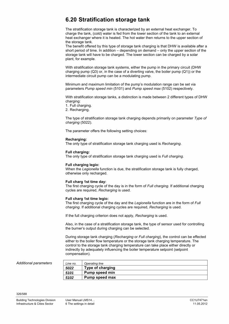
326/588
Building Technologies Division User Manual LMS14… CC1U7471en Infrastructure & Cities Sector 6 The settings in detail 11.05.2012
6.20 Stratification storage tank The stratification storage tank is characterized by an external heat exchanger. To charge the tank, (cold) water is fed from the lower section of the tank to an external heat exchanger where it is heated. The hot water then returns to the upper section of the storage tank. The benefit offered by this type of storage tank charging is that DHW is available after a short period of time. In addition – depending on demand – only the upper section of the storage tank will have to be charged. The lower section can be charged by a solar plant, for example. With stratification storage tank systems, either the pump in the primary circuit (DHW charging pump (Q3) or, in the case of a diverting valve, the boiler pump (Q1)) or the intermediate circuit pump can be a modulating pump. Minimum and maximum limitation of the pump’s modulation range can be set via parameters Pump speed min (5101) and Pump speed max (5102) respectively. With stratification storage tanks, a distinction is made between 2 different types of DHW charging: 1. Full charging. 2. Recharging. The type of stratification storage tank charging depends primarily on parameter Type of charging (5022). The parameter offers the following setting choices: Recharging: The only type of stratification storage tank charging used is Recharging. Full charging: The only type of stratification storage tank charging used is Full charging. Full charging legio: When the Legionella function is due, the stratification storage tank is fully charged, otherwise only recharged. Full charg 1st time day: The first charging cycle of the day is in the form of Full charging. If additional charging cycles are required, Recharging is used. Full charg 1st time legio: The first charging cycle of the day and the Legionella function are in the form of Full charging. If additional charging cycles are required, Recharging is used. If the full charging criterion does not apply, Recharging is used. Also, in the case of a stratification storage tank, the type of sensor used for controlling the burner’s output during charging can be selected. During storage tank charging (Recharging or Full charging), the control can be effected either to the boiler flow temperature or the storage tank charging temperature. The control to the storage tank charging temperature can take place either directly or indirectly by adequately influencing the boiler temperature setpoint (setpoint compensation).
Line no. Operating line
5022 Type of charging 5101 Pump speed min 5102 Pump speed max
Additional parameters

327/588
Building Technologies Division User Manual LMS14… CC1U7471en Infrastructure & Cities Sector 6 The settings in detail 11.05.2012
6.20.1 Stratification storage tank with control to the boiler temperature flow
In the case of control to the boiler temperature setpoint, full charging requires a sensor at the top (B3) and at the bottom (B31) of the storage tank. If the sensor at the bottom is not installed, only recharging is possible, regardless of the parameterized Type of charging (5022). When using control to the boiler temperature setpoint, sensor B36 must not be connected. The boiler temperature setpoint is calculated from the current DHW temperature setpoint and the parameterized Flow setpoint boost (5020): Boiler temperature setpoint = DHW temp setpoint (8831) + Flow setpoint boost (5020) The burner is switched on when the boiler temperature lies by at least the parameterized Switching diff on DHW (2460) below the Boiler setpoint (8311). It is switched off when the boiler temperature lies by at least the parameterized Switching diff off min DHW (2461)/Switching diff off max DHW (2462) above the Boiler setpoint (8311). The output request to the burner is controlled between the parameterized Required speed LF min (9525) and the maximum output in DHW mode Fan speed DHW max (2444). If no maximum output for DHW mode is parameterized (OSV), the burner’s maximum output Required speed HF max (9530) is available. The DHW intermediate circuit pump (Q33) can be activated with a delay in relation to the pump in the primary circuit. The delay is dependent on the rate of boiler temperature increase. For this, Min start temp diff Q33 (5148) can be used to set a temperature differential. The intermediate circuit pump is activated when the boiler temperature reaches the level of current DHW setpoint minus the value set here (in the case of a negative value), or when the boiler temperature exceeds the current DHW setpoint by the value set here (in the case of a positive value). ON Boiler temp (8310) > DHW temp setpoint (8831) + Min start temp diff Q33 (5148) If, subsequently, the boiler temperature drops below this limit, the intermediate circuit pump still remains activated. The temperature differential can be parameterized in the range from -20 K to +20 K. If the temperature differential is set to OSV (---), the intermediate circuit pump is activated with no delay in relation to the pump in the primary circuit. If the pump in the primary circuit (boiler pump (Q1) or DHW charging pump (Q3)) is configured as a modulating pump, it is constantly controlled with the parameterized Pump speed max (5102)) with both types of charging. When the Legionella function is active, the parameterized Legionella funct setpoint (1645) is used as the DHW setpoint.
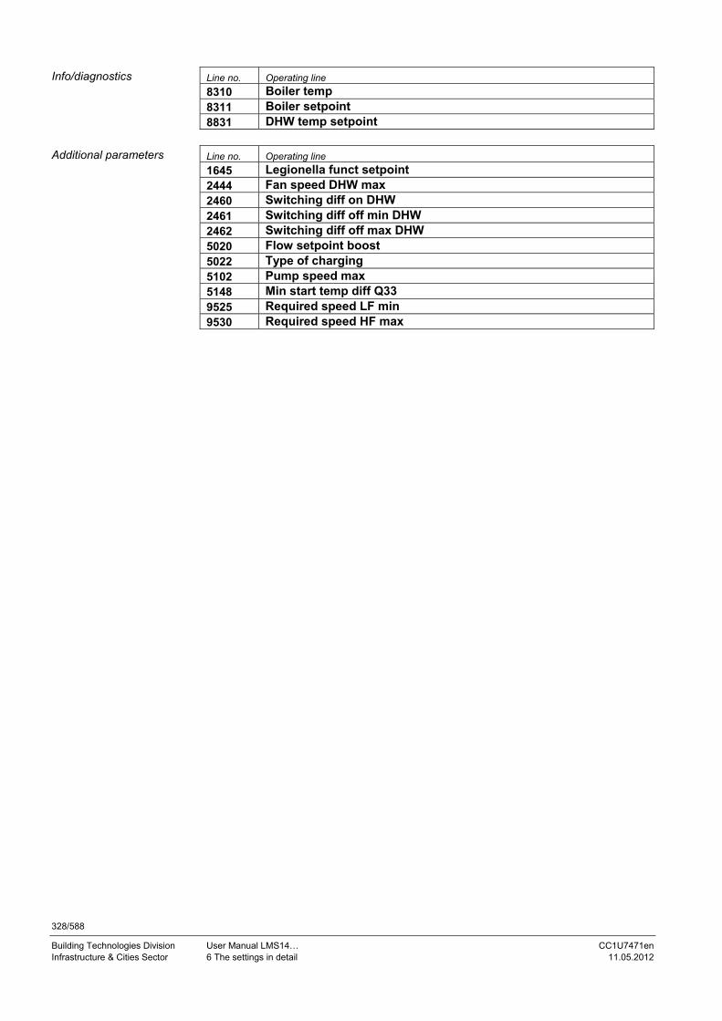
328/588
Building Technologies Division User Manual LMS14… CC1U7471en Infrastructure & Cities Sector 6 The settings in detail 11.05.2012
Line no. Operating line
8310 Boiler temp 8311 Boiler setpoint 8831 DHW temp setpoint
Line no. Operating line
1645 Legionella funct setpoint 2444 Fan speed DHW max 2460 Switching diff on DHW 2461 Switching diff off min DHW 2462 Switching diff off max DHW 5020 Flow setpoint boost 5022 Type of charging 5102 Pump speed max 5148 Min start temp diff Q33 9525 Required speed LF min 9530 Required speed HF max
Info/diagnostics
Additional parameters

329/588
Building Technologies Division User Manual LMS14… CC1U7471en Infrastructure & Cities Sector 6 The settings in detail 11.05.2012
6.20.1.1. Full charging of stratification storage tank With full charging, the entire content of the stratification storage tank is charged to the current DHW setpoint. Full charging requires both sensors (B3 and B31). If sensor B31 at the bottom is not installed, Full charging means Recharging. Charging is aborted if the water temperature at one of the storage tank sensors exceeds the Charging temp max (5050). Charging is continued as soon as the water temperature at that sensor drops by at least 1 K below the maximum storage tank charging temperature and the water temperature at the other sensor has not yet reached the DHW setpoint. Triggering a DHW request: Full charging is started when the water temperature at both storage tank sensors lies by at least the parameterized Switching diff (5024) below the DHW setpoint. ON DHW temp 1 (8830) < DHW temp setpoint (8831) – Switching diff (5024) and DHW temp 2 (8832) < DHW temp setpoint (8831) – Switching diff (5024) Ending a DHW request: Full charging is ended when the entire content of the storage tank reaches the current DHW setpoint. This means that the final criterion is met when the water temperature at both storage tank sensors reaches the DHW setpoint. OFF DHW temp 1 (8830) > DHW temp setpoint (8831) and DHW temp 2 (8832) > DHW temp setpoint (8831) If, during the time full charging is active, the release criterion for full charging does not apply anymore, the DHW request is ended according to the criteria for recharging. Line no. Operating line
8830 DHW temp 1 8831 DHW temp setpoint 8832 DHW temp 2 Line no. Operating line
5024 Switching diff 5050 Charging temp max
Info/diagnostics
Additional parameters

330/588
Building Technologies Division User Manual LMS14… CC1U7471en Infrastructure & Cities Sector 6 The settings in detail 11.05.2012
6.20.1.2. Recharging the stratification storage tank
When recharging, only the upper section of the storage tank is charged to the current DHW setpoint. Triggering a DHW request: Recharging is triggered when the temperature acquired by sensor B3 at the top lies by at least the parameterized Switching diff (5024) below the current DHW setpoint. ON DHW temp 1 (8830) < DHW temp setpoint (8831) – Switching diff (5024) The Boiler setpoint (8311) for recharging is calculated from the DHW setpoint plus the parameterized Flow setpoint boost (5020). Ending a DHW request: Recharging is ended when the temperature acquired by sensor B3 at the top reaches the current DHW setpoint. OFF DHW temp 1 (8830) > DHW temp setpoint (8831) If, during the time recharging is active, the enable criterion for full charging is met, the DHW request is ended according to the criteria for full charging. Line no. Operating line
8311 Boiler setpoint 8830 DHW temp 1 8831 DHW temp setpoint Line no. Operating line
5020 Flow setpoint boost 5024 Switching diff
Info/diagnostics
Additional parameters

331/588
Building Technologies Division User Manual LMS14… CC1U7471en Infrastructure & Cities Sector 6 The settings in detail 11.05.2012
6.20.2 Stratification storage tank with control to the DHW charging temperature via setpoint compensation
Control to the charging temperature allows the entire content of the storage tank to be charged to the required DHW setpoint. This type of control requires a sensor B36 to be configured and connected to one of the multifunctional sensor inputs. In addition, setpoint compensation for DHW charging is to be activated via parameter Flow setp compensation delay (5142), which means that the parameter is not allowed to be OSV (---). Full charging with B36 (5146) can be used to define whether full charging shall be ended when the DHW charging temperature rises. Otherwise, full charging is ended via sensor B31 at the bottom. If the pump in the primary circuit (boiler pump (Q1) or DHW charging pump (Q3)) is configured as a modulating pump, the speed of that pump is modulated in a way that the temperature maintained at sensor B36 is the charging setpoint. The pump’s speed is increased as long as the temperature acquired by sensor B36 lies below the charging setpoint; otherwise, the pump’s speed is reduced. If the DHW intermediate circuit pump (Q33) is configured as a modulating pump, the speed of that pump is modulated in a way that the temperature maintained at sensor B36 is the charging setpoint. The speed of the intermediate circuit pump is reduced until the temperature acquired by sensor B36 lies below the charging setpoint; otherwise, the pump’s speed is increased. The speed of the pump is modulated between the parameterized minimum Pump speed min (5101) and the parameterized maximum Pump speed max (5102). The pump’s speed is controlled via the controller coefficient for the DHW pump (Speed Xp (5103), Speed Tn (5104), and Speed Tv (5105)). The DHW intermediate circuit pump (Q33) can be activated with a delay in relation to the pump in the primary circuit. The delay depends on the rate of boiler temperature increase. For this, Min start temp diff Q33 (5148) can be used to set a temperature differential. The intermediate circuit pump is activated when the boiler temperature reaches the level of current DHW setpoint minus the value set here (in the case of a negative value), or when the boiler temperature exceeds the current DHW setpoint by the value set here (in the case of a positive value). ON Boiler temp (8310) > DHW temp setpoint (8831) + Min start temp diff Q33 (5148) If, subsequently, the boiler temperature drops below this limit, the intermediate circuit pump still remains activated. The temperature differential can be parameterized in the range from -20 K to +20 K. If the temperature differential is set to OSV (---), the intermediate circuit pump is switched on with no delay in relation to the pump in the primary circuit. When the Legionella function is active, the parameterized Legionella funct setpoint (1645) is used as the DHW setpoint.

332/588
Building Technologies Division User Manual LMS14… CC1U7471en Infrastructure & Cities Sector 6 The settings in detail 11.05.2012
Line no. Operating line
8310 Boiler temp 8831 DHW temp setpoint Line no. Operating line
1645 Legionella funct setpoint 5101 Pump speed min 5102 Pump speed max 5103 Speed Xp 5104 Speed Tn 5105 Speed Tv 5142 Flow setp compensation delay 5146 Full charging with B36 5148 Min start temp diff Q33
Info/diagnostics
Additional parameters

333/588
Building Technologies Division User Manual LMS14… CC1U7471en Infrastructure & Cities Sector 6 The settings in detail 11.05.2012
6.20.2.1. Full charging of stratification storage tank With full charging, the entire content of the stratification storage tank is charged to the current DHW setpoint. Full charging with B36 (5146) can be used to define whether full charging shall be ended when the DHW charging temperature rises. This setting makes sense when sensor B31 at the bottom is used for a solar application. Otherwise, full charging is ended via sensor B31 at the bottom. Triggering a DHW request: If sensor B31 is used for solar (Full charging with B36 = Yes) or is not installed, full charging is started when the temperature acquired by sensor B3 at the top lies by at least the parameterized Switching diff (5024) below the current DHW temp setpoint (8831): ON DHW temp 1 (8830) < DHW temp setpoint (8831) – Switching diff (5024) If sensor B31 is installed and not used for solar (Full charging with B36 = No), full charging is started when the temperature at both storage tank sensors lies by at least the parameterized Switching diff (5024) below the DHW temp setpoint (8831): ON DHW temp 1 (8830) < DHW temp setpoint (8831) – Switching diff (5024) and DHW temp 2 (8832) < DHW temp setpoint (8831) – Switching diff (5024) The setpoint for the charging temperature at sensor B36 is calculated from the DHW setpoint plus the parameterized Intermediate circuit boost (5140): Temperature charging setpoint = DHW temp setpoint (8831) + Intermediate circuit boost (5140) First, the Boiler setpoint (8311) results from the DHW temp setpoint (8831) plus the parameterized Flow setpoint boost (5020). Internal boiler temperature setpoint = DHW temp setpoint (8831) + Flow setpoint boost (5020) Setpoint compensation becomes active when the parameterized Flow setp compensation delay (5142) has elapsed. The delay starts when the DHW intermediate circuit pump (Q33) is switched on. Setpoint compensation readjusts the initial boiler temperature setpoint (internally) in a way that the temperature maintained at sensor B36 is the charging setpoint. If the temperature acquired by sensor B36 remains below the charging setpoint, setpoint compensation raises the Boiler setpoint (8311). If the temperature at sensor B36 exceeds the charging setpoint, the Boiler setpoint (8311) is reduced. Setpoint compensation is implemented in the form of a PID controller. Parameters Flow setp compensation Xp (5143), Flow setp compensation Tn (5144), and Flow setp compensation Tv (5145) are used as the controller coefficients. The temperature acquired by sensor B36 serves as the control variable. The Boiler setpoint (8311) is thus the result of the initial boiler temperature setpoint (internally) plus the readjustment calculated by setpoint compensation: Boiler setpoint (8311) = internal boiler temperature setpoint + correction value

334/588
Building Technologies Division User Manual LMS14… CC1U7471en Infrastructure & Cities Sector 6 The settings in detail 11.05.2012
Setpoint compensation has a control range from -100% to +50% and is applied to the parameterized Flow setpoint boost (5020). This means that setpoint compensation can readjust the Boiler setpoint (8311) downward to the DHW temp setpoint (8831) and upward to the DHW temp setpoint (8831) plus 1.5 times the Flow setpoint boost (5020). Ending the DHW request: If sensor B36 is parameterized for detecting the end of full charging (Full charging with B36 = Yes), full charging is ended when the temperature at sensor B36 exceeds the charging setpoint by the value of Excess interm circ temp max (5141), and the temperature acquired by the storage tank sensor at the top reaches the DHW setpoint: OFF DHW temp 1 (8830) > DHW temp setpoint (8831) and DHW charging temp (8836) > Temperature charging setpoint + Excess interm circ temp max (5141) If sensor B31 at the bottom is installed and sensor B36 is not parameterized for detecting the end of full charging (Full charging with B36 = No), full charging is ended when the temperature at both storage tank sensors reaches the DHW setpoint: OFF DHW temp 1 (8830) > DHW temp setpoint (8831) and DHW temp 2 (8832) > DHW temp setpoint (8831) The burner is switched on when the Boiler temp (8310) lies by at least the parameterized Switching diff on DHW (2460) below the Boiler setpoint (8311). It is switched off when the boiler temperature lies by at least the parameterized Switching diff off min DHW (2461)/Switching diff off max DHW (2462) above the Boiler setpoint (8311). The output request to the burner is controlled between the parameterized Required speed LF min (9525) and the maximum output in DHW mode Fan speed DHW max (2444). If no maximum output for DHW mode is parameterized (OSV), the burner’s maximum output, Required speed HF max (9530), will be available. If, during the time full charging is active, the enable criterion for full charging does not apply anymore, the DHW request is ended according to the criteria for recharging.

335/588
Building Technologies Division User Manual LMS14… CC1U7471en Infrastructure & Cities Sector 6 The settings in detail 11.05.2012
Line no. Operating line
8310 Boiler temp 8311 Boiler setpoint 8830 DHW temp 1 8831 DHW temp setpoint 8832 DHW temp 2 8836 DHW charging temp Line no. Operating line
2444 Fan speed DHW max 2460 Switching diff on DHW 2461 Switching diff off min DHW 2462 Switching diff off max DHW 5020 Flow setpoint boost 5024 Switching diff 5140 Intermediate circuit boost 5141 Excess interm circ temp max 5142 Flow setp compensation delay 5143 Flow setp compensation Xp 5144 Flow setp compensation Tn 5145 Flow setp compensation Tv 5146 Full charging with B36 9525 Flow setp compensation Tv
9530 Required speed HF max
Info/diagnostics
Additional parameters

336/588
Building Technologies Division User Manual LMS14… CC1U7471en Infrastructure & Cities Sector 6 The settings in detail 11.05.2012
6.20.2.2. Recharging the stratification storage tank When recharging the stratification storage tank, only the upper section of the tank is charged to the current DHW setpoint. Recharging is started when the temperature acquired by sensor B3 at the top lies by at least the parameterized Switching diff (5024) below the current DHW setpoint: ON DHW temp 1 (8830) < DHW temp setpoint (8831) – Switching diff (5024) Recharging is ended when the temperature acquired by sensor B3 at the top exceeds the DHW setpoint: OFF DHW temp 1 (8830) > DHW temp setpoint (8831) The setpoint for the DHW charging temp (8836) at sensor B36 is calculated from the DHW setpoint plus the parameterized Intermediate circuit boost (5140): Temperature charging setpoint = DHW temp setpoint (8831) + Intermediate circuit boost (5140) The Boiler setpoint (8311) is calculated via setpoint compensation. The mode of operation of setpoint compensation is identical to that with full charging. The burner is switched on when the Boiler temp (8310) lies by at least the parameterized Switching diff on DHW (2460) below the Boiler setpoint (8311). It is switched off when the Boiler temp (8310) lies by at least the parameterized Switching diff off min DHW (2461)/Switching diff off max DHW (2462) above the Boiler setpoint (8311). The output request to the burner is controlled between the parameterized Required speed LF min (9525) and the maximum output in DHW mode, Fan speed DHW max (2444). If no maximum output for DHW mode is parameterized (OSV), the burner’s maximum output, Required speed HF max (9530), will be available. If, during the time recharging is active, the enable criterion for full charging does not apply anymore, the DHW request is ended according to the criteria for full charging. Line no. Operating line
8310 Boiler temp 8311 Boiler setpoint 8830 DHW temp 1 8831 DHW temp setpoint 8836 DHW charging temp Line no. Operating line
2444 Fan speed DHW max 2460 Switching diff on DHW 2461 Switching diff off min DHW 2462 Switching diff off max DHW 5024 Switching diff 5140 Intermediate circuit boost 9525 Required speed LF min 9530 Required speed HF max
Info/diagnostics
Additional parameters

337/588
Building Technologies Division User Manual LMS14… CC1U7471en Infrastructure & Cities Sector 6 The settings in detail 11.05.2012
6.20.3 Stratification storage tank with direct control to the DHW charging temperature
This variant is activated by switching the setpoint compensation off. For this, parameter Flow setp compensation delay (5142) is used to set the delay for setpoint compensation to OSV (---). Control to the charging temperature allows the storage tank to be charged to the required DHW setpoint. This type of control requires a sensor B36 to be configured and connected to one of the multifunctional sensor inputs. Full charging with B36 (5146) can be used to define whether full charging shall be ended when the DHW charging temperature rises. Otherwise, full charging is ended via sensor B31 at the bottom. The pump in the primary circuit (boiler pump (Q1) or DHW charging pump (Q3)) can be a PWM pump. During full charging, this pump is constantly controlled with the parameterized Pump speed min (5101), during recharging, with the parameterized Pump speed max (5102).
Note! If the DHW intermediate circuit pump (Q33) is configured as a modulating pump, it is always controlled with the parameterized minimum speed, regardless of the type of charging.
The DHW intermediate circuit pump (Q33) can be activated with a delay in relation to the pump in the primary circuit. The delay is dependent on the rate of boiler temperature increase. For this, Min start temp diff Q33 (5148) can be used to set a temperature differential. The DHW intermediate circuit pump (Q33) is activated when the boiler temperature reaches the level of current DHW setpoint minus the value set here (in the case of a negative value), or when the boiler temperature exceeds the current DHW setpoint by the value set here (in the case of a positive value). ON Boiler temp (8310) > DHW temp setpoint (8831) + Min start temp diff Q33 (5148) If, subsequently, the boiler temperature drops below this limit, the intermediate circuit pump still remains activated. The temperature differential can be parameterized in the range from -20 K to +20 K. If the temperature differential is set to OSV (---), the intermediate circuit pump is activated with no delay in relation to the pump in the primary circuit. When the Legionella function is active, the parameterized Legionella funct setpoint (1645) is used as the DHW setpoint. Line no. Operating line
8310 Boiler temp 8831 DHW temp setpoint Line no. Operating line
1645 Legionella funct setpoint 5101 Pump speed min 5102 Pump speed max 5142 Flow setp compensation delay 5146 Full charging with B36 5148 Min start temp diff Q33
Info/diagnostics
Additional parameters

338/588
Building Technologies Division User Manual LMS14… CC1U7471en Infrastructure & Cities Sector 6 The settings in detail 11.05.2012
6.20.3.1. Full charging of stratification storage tank With full charging, the entire content of the stratification storage tank is charged to the current DHW setpoint. Full charging requires at least 2 sensors. These are sensor B3 at the top of the storage tank and sensor B36. Sensor B31 at the bottom can be used as an option. But this sensor can also be used for a solar application only. In that case, sensor B36 must be selected for full charging and parameter Full charging with B36 (5146) is to be set to Yes. Triggering a DHW request: If sensor B31 is used for solar (Full charging with B36 = Yes) or is not installed, full charging is started when the temperature acquired by the sensor at the top lies below the switch-on threshold: ON DHW temp 1 (8830) < DHW temp setpoint (8831) – Switching diff (5024) If sensor B31 is installed and not used for solar (Full charging with B36 = No), full charging is started when the temperature at both storage tank sensors lies below the switch-on threshold: ON DHW temp 1 (8830) < DHW temp setpoint (8831) – Switching diff (5024) and DHW temp 2 (8832) < DHW temp setpoint (8831) – Switching diff (5024) During full charging, the burner’s output is controlled to the temperature at sensor B36. The charging setpoint is calculated from the DHW setpoint plus the parameterized Intermediate circuit boost (5140): Temperature charging setpoint = DHW temp setpoint (8831) + Intermediate circuit boost (5140) During full charging, the pump in the primary circuit (boiler pump (Q1) or DHW charging pump (Q3)) is constantly controlled with the parameterized Pump speed min (5101). Ending a DHW request: If sensor B36 is parameterized for detecting the end of full charging (Full charging with B36 = Yes), full charging is ended when the temperature at sensor B36 exceeds the charging setpoint by Excess interm circ temp max (5141), and the temperature acquired by the sensor at the top reaches the DHW setpoint: OFF DHW temp 1 (8830) > DHW temp setpoint (8831) and DHW charging temp (8836) > Temperature charging setpoint + Excess interm circ temp max (5141) If sensor B31 at the bottom is installed and sensor B36 is not parameterized for detecting the end of full charging (Full charging with B36 = No), full charging is ended when the temperature at both storage tank sensors reaches the DHW setpoint: OFF DHW temp 1 (8830) > DHW temp setpoint (8831) and DHW temp 2 (8832) > DHW temp setpoint (8831)

339/588
Building Technologies Division User Manual LMS14… CC1U7471en Infrastructure & Cities Sector 6 The settings in detail 11.05.2012
If, during charging, the temperature at sensor B36 (DHW charging temp (8836)) exceeds the charging setpoint by the current Switching diff off min DHW (2461)/Switching diff off max DHW (2462), the burner is switched off. It is switched on again as soon as the temperature at sensor B36 drops by the parameterized Switching diff on DHW (2460) below the charging temperature setpoint. The setting range for the switch-on differential starts at 0 K. The output request to the burner is controlled between the parameterized Required speed LF min (9525) and the maximum output for Fan speed full charging max (2442). If, during the time full charging is active, the enable criterion for full charging does not apply anymore, the DHW request is ended according to the criteria for recharging. Line no. Operating line
8830 DHW temp 1 8831 DHW temp setpoint 8832 DHW temp 2 8836 DHW charging temp Line no. Operating line
2442 Fan speed full charging max 2460 Switching diff on DHW 2461 Switching diff off min DHW 2462 Switching diff off max DHW 5024 Switching diff 5101 Pump speed min 5140 Intermediate circuit boost 5141 Excess interm circ temp max 5146 Full charging with B36 9525 Required speed LF min
Info/diagnostics
Additional parameters

340/588
Building Technologies Division User Manual LMS14… CC1U7471en Infrastructure & Cities Sector 6 The settings in detail 11.05.2012
6.20.3.2. Recharging the stratification storage tank When recharging the stratification storage tank, only the upper section of the tank is charged to the current DHW temperature setpoint. Recharging is started when the temperature acquired by sensor B3 at the top lies below the switch-on threshold: ON DHW temp 1 (8830) < DHW temp setpoint (8831) – Switching diff (5024) During recharging, the burner’s output is controlled to the temperature acquired by sensor B36. The charging setpoint is calculated from the DHW setpoint plus the parameterized Interm circ boost recharging (5139): Temperature charging setpoint = DHW temp setpoint (8831) + Interm circ boost recharging (5139) During recharging, the pump in the primary circuit (boiler pump (Q1) or DHW charging pump (Q3)) is constantly controlled with the parameterized Pump speed max (5102). Recharging is ended when the temperature acquired by sensor B3 at the top exceeds the DHW setpoint: OFF DHW temp 1 (8830) > DHW temp setpoint (8831) If, during charging, the temperature at sensor B36 (DHW charging temp (8836)) exceeds the charging setpoint by the current Switching diff off min DHW (2461)/Switching diff off max DHW (2462), the burner is switched off. It is switched on again as soon as the temperature at sensor B36 drops by the parameterized Switching diff on DHW (2460) below the charging temperature setpoint. The setting range for the switch-on differential starts at 0 K. The output request to the burner is controlled between the parameterized Required speed LF min (9525) and the maximum output for DHW mode, Fan speed DHW max (2444). If no maximum output for DHW mode is parameterized (OSV), the maximum burner output, Required speed HF max (9530), is available for recharging. If, during the time recharging is active, the enable criterion for full charging is met, the DHW request is ended according to the criteria for full charging. Line no. Operating line
8830 DHW temp 1 8831 DHW temp setpoint 8836 DHW charging temp Line no. Operating line
2444 Fan speed DHW max 2460 Switching diff on DHW 2461 Switching diff off min DHW 2462 Switching diff off max DHW 5024 Switching diff 5102 Pump speed max 5139 Interm circ boost recharging 9525 Required speed LF min 9530 Required speed HF max
Info/diagnostics
Additional parameters

341/588
Building Technologies Division User Manual LMS14… CC1U7471en Infrastructure & Cities Sector 6 The settings in detail 11.05.2012
6.21 Instantaneous water heater To prevent scalding in the event sensor B38 is faulty (sensor B39 also, depending on the type of system), both consumption and keeping hot operation are suppressed. Any request from space heating is immediately satisfied, even if the DHW flow switch is active. To ensure protection against scalding, DHW consumption via the tap must be accepted only in the case of instantaneous water heaters with primary heat exchanger (partial diagram BwDl2). Burner startup is prevented in this case. During the time DHW is consumed, a pending request from space heating cannot be satisfied, since this would affect the water temperature at the tap as well.
6.21.1 Control
Line no. Operating line
5420 Flow setpoint boost Here, set the boost of the flow temperature setpoint for instantaneous water heater operation. The boost acts only if control is not dependent on sensor B38 and only applies to consumption and Keep hot operation.
Line no. Operating line
5429 Switching diff Here, set the switching differential for the instantaneous water heater. It applies to consumption and Keep hot operation.
6.21.2 DHW consumption (flow)
Line no. Operating line
5444 Threshold flow detection DHW consumption is detected when: DHW flow > threshold flow detection.
Line no. Operating line
5445 Switching diff flow detection DHW consumption is no longer detected when: DHW flow < threshold flow detection minus switching differential flow detection. The measured DHW flow can be read via parameter DHW flow (8860).
Line no. Operating line
8860 DHW flow
Behavior in the event of sensor failure
Flow setpoint boost
Switching diff
Threshold flow detection
Switching diff flow detection
Info/diagnostics

342/588
Building Technologies Division User Manual LMS14… CC1U7471en Infrastructure & Cities Sector 6 The settings in detail 11.05.2012
6.21.3 DHW consumption (gradient)
Line no. Operating line
5450 Gradient end cons This parameter is used to define the temperature gradient at sensor B38 with which – in the case of aqua booster operation – the end of consumption is detected. With Aqua booster Ge [4765.1], sensor B39 is used for detection (in place of B38).
Line no. Operating line
5451 Gradient start cons keep hot This parameter is used to define the temperature gradient at sensor B38 from which – in the case of aqua booster operation – consumption is detected when the Keep hot function is activated. With Aqua booster Ge [4765.1], sensor B39 is used for detection (in place of B38).
Line no. Operating line
5452 Gradient start cons This parameter is used to define the temperature gradient at sensor B38 from which – in the case of aqua booster operation – consumption is detected. With Aqua booster Ge [4765.1], sensor B39 is used for detection (in place of B38).
Line no. Operating line
5455 Setp readj cons 40°C Correction value for the setpoint on the LMS14... with a consumption setpoint of 40 °C.
Line no. Operating line
5456 Setp readj cons 60°C Correction value for the setpoint on the LMS14... with a consumption setpoint of 60 °C.
Gradient end cons
Gradient start cons keep hot
Gradient start cons
Setp readj cons 40°C
Setp readj cons 60°C

343/588
Building Technologies Division User Manual LMS14… CC1U7471en Infrastructure & Cities Sector 6 The settings in detail 11.05.2012
6.21.4 Keep hot function
Line no. Operating line
5460 Setpoint keep hot Temperature setpoint of the Keep hot function.
Line no. Operating line
5461 Readj setp keep hot 40°C Correction value for the setpoint on the 2-position controller with a keep-hot setpoint of 40 °C.
Line no. Operating line
5462 Readj setp keep hot 60°C Correction value for the setpoint on the 2-position controller with a keep-hot setpoint of 60 °C.
Line no. Operating line
5464 Keep hot release 24h/day
DHW release
Time program 3/HC3
Time program 4/DHW
Time program 5 Release of Keep hot function.
Line no. Operating line
5468 Min cons time for keep hot Here, set the minimum consumption time activating the Keep hot function.
Line no. Operating line
5470 Keep hot time wo heating Duration of Keep hot function when there is no request for space heating.
Line no. Operating line
5471 Keep hot time with heating Duration of Keep hot function when, at the same time, there is a request for space heating.
Line no. Operating line
5472 Pump overrun time keep hot Here, set the period of time (in minutes) the pump still runs on burner shutdown during the Keep hot function.
Line no. Operating line
5473 Pump overrun time keep hot Here, set the period of time (in seconds) the pump still runs on burner shutdown during the Keep hot function.
Note! The effective pump overrun time is obtained by adding up Pump overrun time keep hot (5472) and Pump overrun time keep hot (5473).
Setpoint keep hot
Readj setp keep hot 40°C
Readj setp keep hot 60°C
Keep hot release
Min cons time for keep hot
Keep hot time wo heating
Keep hot time with heating
Pump overrun time keep hot (in minutes)
Pump overrun time keep hot (in seconds)

344/588
Building Technologies Division User Manual LMS14… CC1U7471en Infrastructure & Cities Sector 6 The settings in detail 11.05.2012
Line no. Operating line
5475 Control sensor keep hot Boiler sensor B2 Return sensor B7 DHW outlet sensor B38
Select the control sensor (2-position controller) for the Keep hot function. Boiler sensor B2 The burner is switched on and off based on a temperature comparison with the boiler temperature. Return sensor B7 The burner is switched on and off based on a temperature comparison with the boiler return temperature. DHW outlet sensor B38 The burner is switched on and off based on a temperature comparison with the DHW outlet temperature.
6.21.5 Times
Line no. Operating line
5482 Flow switch time cons This parameter is used to define the minimum response time of the flow switch for detecting consumption.
6.21.6 Overrun
Line no. Operating line
5489 Overrun via inst WH No Yes
No The boiler’s residual heat is supplied to the heating circuit. Yes The boiler’s residual heat is supplied to the heat exchanger of the instantaneous water heater.
Control sensor keep hot
Flow switch time cons
Overrun via inst WH

345/588
Building Technologies Division User Manual LMS14… CC1U7471en Infrastructure & Cities Sector 6 The settings in detail 11.05.2012
6.21.7 Speed-controlled pump Pump Q34 of the instantaneous water heater can be a speed-controlled pump. When DHW is consumed, speed control of Q34 is ensured by a PID controller. The speed of this pump is calculated such that the water temperature reached at sensor B38 represents the setpoint at the tap. If the temperature acquired by B38 exceeds the setpoint required at the tap, the speed is reduced, otherwise it is increased. The controller coefficients are ready set. The neutral zone is ±0.4 K. In Keep hot operation, the speed of the instantaneous water heater pump is maintained at the parameterized minimum level. The resulting speed is delivered according to the configuration made at PWM output P1 (Function output P1 (6085)). In the case of hydraulic systems with diverting valve and speed-controlled boiler pump, the speed calculated for the instantaneous water heater pump can be used for controlling the boiler pump. For that, modulation mode Demand must be selected for the boiler pump (refer to Pump modulation (2320)) and PWM output P1 (Function output P1 (6085)) must be configured for use with the boiler pump. Also, in that case, the speed limitations for the instantaneous water heater pump are used for the control of the boiler pump.
Line no. Operating line
5530 Pump speed min Minimum speed limit for the pump of the instantaneous water heater (heating expert).
Line no. Operating line
5531 Pump speed max Maximum speed for the instantaneous water heater pump (heating expert).
Line no. Operating line
5535 Pump speed min OEM Lower speed limit for the pump of the instantaneous water heater (OEM).
Line no. Operating line
5536 Pump speed max OEM Upper speed limit for the pump of the instantaneous water heater (OEM).
Line no. Operating line
5537 Starting speed Speed of pump of the instantaneous water heater for the start kick.
Pump speed min
Pump speed max
Pump speed min OEM
Pump speed max OEM
Starting speed

346/588
Building Technologies Division User Manual LMS14… CC1U7471en Infrastructure & Cities Sector 6 The settings in detail 11.05.2012
6.21.8 Configuration
Basics of instantaneous water heater (function) To configure an instantaneous water heater, the DHW sensor connected to terminal B3/B38 must be parameterized as sensor B38. For that, use parameter DHW sensor (5730) and select DHW outlet sensor B38. Parameter DHW controlling element (5731) is used to select the type of controlling element (diverting valve or charging pump). Control of this controlling element must be assigned to at least one output (QX1, QX2, QX3, QX4/WX1) (parameters Relay output QX1 (5890), Relay output QX2 (5891), Relay output QX3 (5892), Relay output QX4 (5894)). Here, select Instant WH ctrl element Q34. For the control of a diverting valve, output QX3 has a changeover contact. Parameter Aqua booster (5550) is used to determine whether there is an aqua booster.
Line no. Operating line
5550 Aqua booster No Yes Yes, wo gradient detection
Aqua booster setting. No No aqua booster configured. Yes Aqua booster configured. Yes, wo gradient detection Aqua booster configured, but detection of consumption via gradient is not activated. Consumption is detected via flow switch or flow. Parameter Overrun via inst WH (5489) is used to select whether the boiler’s residual heat shall be fed to the heat exchanger of the instantaneous water heater or to the heating circuit. Line no. Operating line
5489 Overrun via inst WH 5530 Pump speed min 5531 Pump speed max 5535 Pump speed min OEM 5536 Pump speed max OEM 5537 Starting speed 5730 DHW sensor 5731 DHW controlling element 5890 Relay output QX1 5891 Relay output QX2 5892 Relay output QX3
Configuration of instantaneous water heater
Aqua booster
Additional parameters

347/588
Building Technologies Division User Manual LMS14… CC1U7471en Infrastructure & Cities Sector 6 The settings in detail 11.05.2012
The diverting valve is driven to the position demanded by the current heat request: DHW or space heating (heating circuit). If there is no request for heat, the diverting valve assumes its basic position. This can be selected via parameter Basic pos DHW div valve (5734). The following choices are available:
Last request (0): Diverting valve maintains the position resulting from the last heat request
Heating (1): Diverting valve is driven to the position for space heating DHW (2): Diverting valve is driven to the position for DHW heating
Note! Thus far, with the instantaneous water heater (Build 43), only the options Last request and DHW have been implemented. In the case of space heating, the diverting valve behaves the same like with option Last request.
During the time the diverting valve is driven to the other position, it may be necessary to temporarily deactivate the pump. Using parameter Pump off change div valve (5732), the period of time the pump shall be deactivated can be set. Parameter Delay pump off (5733) can be used to parameterize a temporal offset of pump shutdown against the control of the diverting valve.
Line no. Operating line
5732 Pump off change div valve 5733 Delay pump off 5734 Basic pos DHW div valve
To detect DHW consumption in the case of the instantaneous water heater, a flow switch can be connected. To ensure that DHW consumption is reliably detected, it may be necessary for the flow switch to respond for a certain minimum time, which can be parameterized. For this purpose, parameter Flow switch time cons (5482) is available. Setting 0 means that DHW consumption is detected the very same moment a change of state occurs. The flow switch can be in the form of a switching contact or rate-of-flow meter.
Line no. Operating line
5482 Flow switch time cons
Diverting valve
Additional parameters
Flow switch
Additional parameters

348/588
Building Technologies Division User Manual LMS14… CC1U7471en Infrastructure & Cities Sector 6 The settings in detail 11.05.2012
A flow switch in the form of a switching contact can be connected to input H1, H3, H4, H5, H6 or H7. Due to their long response time, inputs H2 on the extension modules are not suited as inputs for a DHW flow switch. For this purpose, this input is to be configured as a DHW flow switch via one of the function inputs Hx (Function input H1 (5950), Function input H3 (5960), Function input H4 (5970), Function input H5 (5977), Function input H6 (6008) and Function input H7 (6011)).
Line no. Operating line 5950 Function input H1 5960 Function input H3 5970 Function input H4 5977 Function input H5 6008 Function input H6 6011 Function input H7 A flow switch in the form of a rate-of-flow meter can be connected to input H4 (frequency input). For that, the input is to be configured via parameter Function input H4 (5970) as DHW flow switch. Also, the characteristics of the rate-of-flow meter are to be defined via 2 pairs of value consisting of a frequency value and a function value. The resolution for the function value is 100 ml/min. This means that for a flow rate of 2 l/min, the function value to be set is 20. Menu DHW flow heater (instantaneous water heater) contains parameter Threshold flow detection (5444) which is used to enter the threshold above which the flow rate indicates DHW consumption. In addition, parameter Switching diff flow detection (5445) is to be used to enter the hysteresis as a switching differential. The rate-of-flow meter is to be selected as flow switch via parameter Flow supervision [4196.1] of the Boiler menu.
Line no. Operating line 5444 Threshold flow detection 5445 Switching diff flow detection 5970 Function input H4 5973 Frequency value 1 H4 5974 Function value 1 H4 5975 Frequency value 2 H4 5976 Function value 2 H4 [4196.1] Flow supervision
Both types of flow switch can be used simultaneously. In that case, DHW consumption is detected via an OR operation of both inputs. For detection, it is sufficient if one of the 2 inputs indicates consumption. When the end of DHW consumption is reached, none of the 2 inputs must indicate consumption.
Switching contact
Additional parameters
Rate-of-flow meter
Additional parameters
Combination of switching contact and rate-of-flow meter

349/588
Building Technologies Division User Manual LMS14… CC1U7471en Infrastructure & Cities Sector 6 The settings in detail 11.05.2012
In the case of DHW systems with instantaneous water heater, the following operating modes can be selected via operating mode changeover (operator terminal/room unit):
DHW mode Off (no bar on the display) DHW mode ECO On (single bar on the display) DHW mode On (double bar on the display)
When selecting DHW mode Off, frost protection for DHW remains activated. With DHW mode ECO On, DHW heating is activated, but Keep hot operation is deactivated. In general, Keep hot operation is only enabled with DHW mode On. In operating mode Off, frost protection for DHW remains active. Frost protection becomes active as soon as the temperature acquired by sensor B38 drops below 5 °C. In that case, a heat request is sent to the burner. The temperature setpoint for the burner is generated by adding the parameterized Flow setpoint boost (5420) to the Setpoint keep hot (5460). Frost protection is ended when the temperature acquired by sensor B38 reaches a level of least 7 °C. When frost protection is ended, pump overrun starts. With instantaneous water heaters, a distinction between 2 operating modes is made. An open tap means DHW consumption. When the tap is opened, DHW should be supplied at the preselected temperature as quickly as possible. In addition, the Keep hot function is used. This function ensures that the water contained in the heat exchanger is preheated. This means that next time DHW is drawn, it will be available more quickly. The disadvantage in terms of convenience in comparison with a DHW storage tank can thus be minimized. DHW consumption is detected either via a flow switch or via the water temperature gradient in the heat exchanger (aqua booster). During DHW consumption, requests from space heating are generally ignored. This means that the burner’s output is solely used for DHW heating. During DHW consumption, the burner’s output is modulated in a way that the water temperature at the outlet reaches the setpoint as quickly as possible, even if the amount of water drawn varies. If the heat exchanger is kept at a certain temperature level, comfort of instantaneous water heating systems is enhanced. The water in the heat exchanger is heated up to the Keep hot setpoint. This means that next time DHW is drawn, it will be available more quickly. The Keep hot function can be activated to have it either permanently On, or only for a limited period of time after consumption. If confined to the point in time after consumption, the minimum consumption time on completion of which the Keep hot function shall be started can be set. In the case of plants with diverting valve, the valve maintains the DHW position during the Keep hot function, even if the heat exchanger reaches the Keep hot setpoint. If DHW consumption follows, there is no need for the diverting valve to first travel to the required position. As a result, requests from space heating cannot be fulfilled during the time the Keep hot function is active. Nevertheless, to make certain that this situation will not lead to a considerable reduction in room comfort, 2 values can be parameterized for the period of time the Keep hot function is active: One value for the situation when there is no request for heat from the space, and one value when the space calls for heat also.
DHW operating modes
Frost protection
Operating modes of instantaneous water heater
DHW consumption
Keep hot function

350/588
Building Technologies Division User Manual LMS14… CC1U7471en Infrastructure & Cities Sector 6 The settings in detail 11.05.2012
Instantaneous water heater with primary heat exchanger
In the case of instantaneous water heaters with primary heat exchanger, the heat exchanger is heated up directly by the burner’s flame. Hence, there is no heat transfer from the boiler water to the DHW. When DHW is consumed, the burner is controlled depending on the DHW outlet temperature (sensor B38). The burner is switched on when the DHW outlet temperature lies one switching differential below the setpoint of consumption. The burner is switched off again when the DHW outlet temperature exceeds the setpoint by the current switch-off differential. The switch-off differential is calculated dynamically, based on the parameterized minimum and maximum switch-off differential. When DHW is consumed, the burner’s output is controlled depending on the DHW outlet temperature (sensor B38), but the boiler temperature is limited. Parameter Boiler temp output reduction (2527) is used to set the temperature limit. The associated switching differential is set via parameter Swi diff output reduction (2528). Line no. Operating line 1610 Nominal setpoint 2460 Switching diff on DHW 2461 Switching diff off min DHW 2462 Switching diff off max DHW 2463 Settling time DHW 5020 Flow setpoint boost 2527 Boiler temp output reduction 2528 Swi diff output reduction Line no. Operating line 8003 State DHW 8852 DHW consumption temp 8853 Instant WH setpoint The Keep hot function is not available with instantaneous water heaters equipped with a primary heat exchanger.
DHW consumption
Additional parameters
Info/diagnostics
Keep hot function

351/588
Building Technologies Division User Manual LMS14… CC1U7471en Infrastructure & Cities Sector 6 The settings in detail 11.05.2012
Instantaneous water heater with secondary heat exchanger and water outlet sensor In the case of instantaneous water heaters equipped with a secondary heat exchanger, the boiler water is always heated up by the flame. The secondary heat exchanger transfers the heat from the boiler water to the DHW. When DHW is consumed, the burner is controlled depending on the DHW outlet temperature (sensor B38). The burner is switched on when the DHW outlet temperature lies one switching differential below the setpoint of consumption. The burner is switched off again when the DHW outlet temperature exceeds the setpoint by the current switch-off differential. The switch-off differential is calculated dynamically, based on the parameterized minimum and maximum switch-off differential. When DHW is consumed, the burner’s output is controlled depending on the DHW outlet temperature (sensor B38), but the boiler temperature is limited. Parameter Boiler temp output reduction (2527) is used to set the temperature limit. The associated switching differential is set via parameter Swi diff output reduction (2528). Line no. Operating line 1610 Nominal setpoint 2460 Switching diff on DHW 2461 Switching diff off min DHW 2462 Switching diff off max DHW 2463 Settling time DHW 5020 Flow setpoint boost 2527 Boiler temp output reduction 2528 Swi diff output reduction Line no. Operating line 8003 State DHW 8852 DHW consumption temp 8853 Instant WH setpoint
DHW consumption
Additional parameters
Info/diagnostics

352/588
Building Technologies Division User Manual LMS14… CC1U7471en Infrastructure & Cities Sector 6 The settings in detail 11.05.2012
When the Keep hot function is activated, the burner is controlled via the selected control sensor. The following sensors are available as control sensors:
Boiler flow (sensor B2) Boiler return (sensor B7) Sensor B38
The control sensor for the Keep hot function is selected via parameter Control sensor keep hot (5475). The temperature setpoint for the Keep hot function is adjusted via parameter Setpoint keep hot (5460). If this parameter is set to OSV (---), the current DHW setpoint is also used for the Keep hot function. When the Keep hot function is activated, the burner’s output is not modulated. Also, the burner operates at minimum output. It is switched on when the temperature acquired by the keep hot sensor lies at least one switching differential (Switching diff on DHW (2460)) below the setpoint of the Keep hot function. The burner is switched off again when the temperature at the keep hot sensor exceeds the setpoint of the Keep hot function by the minimum switch-off differential (Switching diff off min DHW (2461)). When the burner has shut down, it may be practical to also deactivate the pump (charging pump or boiler pump). The 2 parameters Pump overrun time keep hot (5072) and Pump overrun time keep hot (5473) can be used to set the period of time the pump shall overrun when – in the case of the Keep hot function – the burner has shut down. The first parameter is used for setting the minutes (0…255 minutes), the second for setting the seconds (0…240 seconds). The resulting pump overrun time is then the sum of both parameters. If set to 255 minutes, the pump is not switched off during the time the Keep hot function is active, even if the burner is not in operation. On applications with diverting valve, the valve maintains the DHW position during the time the Keep hot function is active. If there is no diverting valve, requests from space heating can be considered – in addition to the Keep hot function. In that case, burner modulation is enabled. The burner’s output is controlled according to the control sensor parameterized for the Keep hot function. Line no. Operating line 2460 Switching diff on DHW 2461 Switching diff off min DHW 5460 Setpoint keep hot 5464 Keep hot release 5468 Min cons time for keep hot 5470 Keep hot time wo heating 5471 Keep hot time with heating 5472 Pump overrun time keep hot 5473 Pump overrun time keep hot 5475 Control sensor keep hot 5482 Flow switch time cons Line no. Operating line 8003 State DHW 8852 DHW consumption temp 8853 Instant WH setpoint
Keep hot function
Additional parameters
Info/diagnostics

353/588
Building Technologies Division User Manual LMS14… CC1U7471en Infrastructure & Cities Sector 6 The settings in detail 11.05.2012
After DHW consumption, activation of the heat exchanger’s Keep hot function can be parameterized for a certain period of time. Parameter Min cons time for keep hot (5468) allows the Keep hot function to be activated only when the consumption time reaches this minimum time period. If, during the time the Keep hot function is active, there is a request for space heating, the time the Keep hot function shall be active can be set between 0 and 30 minutes, using parameter Keep hot time with heating (5471). If there is no request for space heating, the period of time the Keep hot function shall be active can be set between 0 and 140 minutes using parameter Keep hot time wo heating (5470). If set to 1,440 minutes, continuous operation starts (see below). If, during the time the Keep hot function is active, there is a request for space heating, the function is stopped or aborted, if the parameterized time (space heating request active (Keep hot time with heating (5471)) has already elapsed. If there is no more request from space heating and the parameterized time (space heating request inactive (Keep hot time wo heating (5470)) has not yet elapsed, the Keep hot function is resumed. Another option to keep the heat exchanger at the required temperature level is continuous operation. To ensure that the heat exchanger is brought to the Keep hot setpoint not only after DHW consumption – to be kept at that level for a limited period of time –, but always when the heat exchanger’s temperature drops by one switching differential below the Keep hot setpoint, the heat exchanger is recharged.
Keep hot function after consumption (time limited)
Keep hot function continuous operation

354/588
Building Technologies Division User Manual LMS14… CC1U7471en Infrastructure & Cities Sector 6 The settings in detail 11.05.2012
Instantaneous water heater with secondary heat exchanger without water outlet sensor (aqua booster) When using an aqua booster, sensor B38 is not installed by the water outlet, but in the heat exchanger itself, close to the cold water inlet. Configuration of an aqua booster requires option Yes, using parameter Aqua booster (5550). Special features of aqua boosters:
DHW consumption is detected by sensor B38, based on the heat exchanger’s temperature gradient
When DHW is consumed, the burner’s output is controlled depending on the boiler return temperature (from the heat exchanger to the boiler)
To ensure that DHW consumption can be detected via the heat exchanger’s temperature gradient, the heat exchanger must always be kept at a certain temperature level. For this reason, the Keep hot function for the aqua booster is always enabled
Detection of DHW consumption with the aqua booster is performed via the temperature gradient at sensor B38. With the aqua booster, that sensor in located in the heat exchanger itself, close to the cold water inlet. When DHW is consumed, the temperature acquired by that sensor drops when cold water enters the heat exchanger. If a flow switch is connected and configured, DHW consumption can also be detected by the flow switch. DHW consumption is detected when either the flow switch or the temperature gradient indicates consumption. The end of consumption is detected when neither the flow switch nor the gradient indicates consumption. If DHW consumption shall be indicated by the flow switch only, parameter Aqua booster (5550)offers option Yes, wo gradient detection. When DHW is consumed, the burner is controlled depending on the boiler return temperature (sensor B7). The boiler return temperature represents a good indication of the DHW outlet temperature. The burner is switched on when the boiler return temperature drops one switching differential below the setpoint of consumption. The burner is switched off again when the boiler return temperature exceeds the setpoint of consumption by the current switch-off differential. The switch-off differential is calculated dynamically, based on the parameterized minimum and maximum switch-off differential. When DHW is consumed, the burner is controlled depending on the boiler return temperature (sensor B7), but the boiler temperature is limited. Parameter Boiler temp output reduction (2527) is used to set the temperature limit. The associated switching differential is set via parameter Swi diff output reduction (2528). Line no. Operating line 1610 Nominal setpoint 2460 Switching diff on DHW 2461 Switching diff off min DHW 2462 Switching diff off max DHW 2463 Settling time DHW 5020 Flow setpoint boost 5550 Aqua booster 2527 Boiler temp output reduction 2528 Swi diff output reduction
DHW consumption
Additional parameters

355/588
Building Technologies Division User Manual LMS14… CC1U7471en Infrastructure & Cities Sector 6 The settings in detail 11.05.2012
Line no. Operating line 8310 Boiler temp 8313 Switch point DHW operation 8314 Boiler return temp 8831 DHW temp setpoint 8852 DHW consumption temp 8853 Instant WH setpoint With the aqua booster, the Keep hot function is always enabled. ECO mode for DHW is not available here. After DHW consumption, the Keep hot function is always activated.
Instantaneous water heater with secondary heat exchanger, DHW outlet and inlet sensor (aqua-booster)
This type of aqua booster always requires 2 DHW sensors (sensor B38 and B39) and does not use a flow switch. The configuration of this type of aqua booster is made via parameter Aqua booster Ge [4765.1]. Line no. Operating line
[4765.1] Aqua booster Ge Off
On Off This setting is used to configure the variant Aqua booster without outlet sensor and with optional flow switch. On This setting is used to configure the variant Aqua booster with B38 and B39, but without flow switch. Sensor B39, which acquires the DHW inlet temperature, is screwed into the DHW inlet of the secondary plate heat exchanger. Sensor B38, which controls the DHW outlet temperature, is fitted to the pipe directly downstream from the secondary plate heat exchanger at the DHW outlet. To be able to detect a DHW request, a fast temperature drop in the secondary plate heat exchanger is required. For this reason, the secondary heat exchanger must always be kept at a certain temperature level. This is ensured by the Keep hot DHW comfort function. The Keep hot function is always started at the end of a DHW request. When operating mode Keep hot is active, the burner operates at minimum output. The 3-port valve is in the DHW position.
Note! If Aqua Booster Ge [4765.1] is set to On, sensor B39 must be connected and Aqua booster (5500) must not be set to No.
Info/diagnostics
Keep hot function
Keep hot function after DHW consumption
Aqua booster Ge

356/588
Building Technologies Division User Manual LMS14… CC1U7471en Infrastructure & Cities Sector 6 The settings in detail 11.05.2012
Keep hot function
The Keep hot function is also activated and deactivated by the DHW inlet temperature acquired by sensor B39, provided no operating mode of higher priority is active. The setpoint for the sensor B39 is determined by the adjusted Setpoint keep hot (5460). If this parameter is set to OSV, the current setpoint for DHW consumption is used as the Keep hot setpoint. If, on completion of DHW consumption, a change to Comfort mode Keep hot is made, a timer is started, running for the period of time ParTimeMinWarmhaltungEin. The Keep hot function remains active as long as the timer runs. This ensures that the Comfort function is active for a minimum period of time. The reason for the minimum on time is to make certain that – at the end of DHW consumption – the plate heat exchanger is maintained at the Keep hot setpoint for a certain period of time, in case DHW consumption is interrupted for a moment (when taking a shower: water consumption - end of consumption - soaping - water consumption; when opening the tap the second time, cold water is not wanted; the boiler water may cool down the DHW storage tank, the reason being the low setpoint of the heating circuit). To force the burner to shut down on completion of DHW consumption when changing to Comfort mode (preventing scalding if consumption is interrupted for a moment), a timer can be parameterized, running for the period of time ParTimeBurnerOffAquaBoost. When changing from DHW heating to the Keep hot function, the burner remains Off for the parameterized period of time. Detection of DHW consumption via sensor B39 To keep the plate heat exchanger at a certain temperature level, the Keep hot function is used. It maintains the DHW inlet temperature at a high level, thus ensuring a sufficiently high temperature differential (falling ΔT/Δt gradient) to trigger DHW mode. To detect the end of DHW consumption, the gradient must be rising (slope must be sufficiently steep). On completion of DHW consumption, a change to the Keep hot function can be made, thus enabling the DHW inlet temperature acquired by sensor B39 to return to a higher level. This takes place when the above described switch-on condition for the Keep hot function is satisfied. The burner is started up by the 2-position controller. When DHW consumption is detected via a sufficiently steep negative temperature gradient of the DHW inlet temperature, the 2-position controller puts the burner into operation. If the temperature acquired by sensor B38 (DhwOut) lies below the DHW setpoint, the switch-on condition for the burner is satisfied. If the actual value were above the setpoint plus the switch-off threshold, the burner would not be put into operation by the 2-position controller. Deactivating the DHW mode via comparison of the absolute temperature values (aqua booster) In addition to the positive gradient which – if the slope suffices – ends the DHW mode, a second criterion can be activated, ending the DHW mode. Here, the 2 absolute temperature values of sensor B38 (DHWOut) and sensor B39 (DHWIn) are compared. If the differential is smaller than threshold Abs TempSwiOffThresh [°C] [4772.1], the DHW mode is ended. If the 2 temperatures approach one another, it can be assumed that there is no DHW consumption. Comparison of the absolute temperatures can be activated or deactivated via Abs SwiOffCondAquaB [4766.1].

357/588
Building Technologies Division User Manual LMS14… CC1U7471en Infrastructure & Cities Sector 6 The settings in detail 11.05.2012
Line no. Operating line
[4766.1] Abs SwiOffCondAquaB Off On
Activation of comparison of absolute temperature values as the final criterion of DHW consumption. Increased output with the Keep hot function (aqua booster) If the minimum burner output is not able to deactivate the Keep hot function, parameter Interv outp increase [4771.1] can be used to set a period of time on completion of which the burner’s output is increased. The timer is reloaded after the burner’s output has been increased. The output is increased until the maximum is reached. The minimum output is summed up with each additional stage. The function of multistage output increase in the Keep hot mode can be activated via parameter Output increase AquaB [4767.1]. Line no. Operating line
[4767.1] Output increase AquaB Activation of multistage increase of output to end the Keep hot function. Line no. Operating line
[4768.1] Min KeepHotTime AquaB Minimum on time of Keep hot function on completion of DHW consumption. Line no. Operating line
[4769.1] Interv burner off time Interval for Burner off when changing from DHW consumption to the Keep hot function. Line no. Operating line
[4770.1] Interv burner on time Not in use, not implemented. Line no. Operating line
[4771.1] Interv outp increase Period of time on completion of which a change to the next stage of output increase is made. Line no. Operating line
[4772.1] Abs TempSwiOffThresh Absolute temperature threshold for absolute temperature comparison of outlet temperature at sensor B38 and inlet temperature at sensor B39 to end the Keep hot function, if required. Line no. Operating line
[4773.1] Pump overrun AquaB Not in use, not implemented.
Abs SwiOffCondAquaB
Output increase AquaB
Min KeepHotTime AquaB
Interv burner off time
Interv burner on time
Interv outp increase
Abs TempSwiOffThresh
Pump overrun AquaB

358/588
Building Technologies Division User Manual LMS14… CC1U7471en Infrastructure & Cities Sector 6 The settings in detail 11.05.2012
Line no. Operating line
[4774.1] Pump overr KeepHotEnd Not in use, not implemented. Line no. Operating line
[4775.1] OnDiff KeepHot AquaB Switch-on differential for the Keep hot function. Line no. Operating line
[4776.1] OffDiff KeepHot AquaB Switch-off differential for the Keep hot function.
Pump overr KeepHotEnd
OnDiff KeepHot AquaB
OffDiff KeepHot AquaB

359/588
Building Technologies Division User Manual LMS14… CC1U7471en Infrastructure & Cities Sector 6 The settings in detail 11.05.2012
6.21.9 Setpoint readjustment
Basics of setpoint readjustment To be able to compensate for temperature deviations resulting from unfavorable sensor locations, for instance, the setpoint can be readjusted. For setpoint readjustments, 2 correction values must be parameterized: One for the setpoint of 40 °C, and one for the setpoint of 60 °C. These 2 values define a straight line which delivers the correction values for all other setpoints. Setpoint readjustments can be made separately for DHW consumption and the Keep hot function. If the consumption setpoint is changed, the LMS14... can automatically change the keep-hot setpoint as well, if required. For that, the keep-hot setpoint on Setpoint keep hot (5460) must be set to OSV (---) Using the setpoint readjustment, correction values can be parameterized for the setpoints of 40 °C and 60 °C. These 2 points define a linear readjustment of any keep-hot setpoints. Line no. Operating line 8852 DHW consumption temp 8853 Instant WH setpoint For setpoint readjustments during DHW consumption, the 2 correction values for the consumption setpoints of 40 °C and 60 °C must be parameterized. If both are set to 0, there will be no readjustment of the consumption setpoint. Line no. Operating line 5455 Setp readj cons 40°C 5456 Setp readj cons 60°C For setpoint readjustments in connection with the Keep hot function, the 2 correction values for the Keep hot setpoints of 40 °C and 60 °C must be parameterized. If both are set to 0, there will be no readjustment of the Keep hot setpoint. Line no. Operating line
5461 Readj setp keep hot 40°C 5462 Readj setp keep hot 60°C
Keep-hot setpoint dependent on consumption setpoint
Info/diagnostics
DHW consumption
Additional parameters
Keep hot function
Additional parameters

360/588
Building Technologies Division User Manual LMS14… CC1U7471en Infrastructure & Cities Sector 6 The settings in detail 11.05.2012
6.22 Configuration
Note! During the reconfiguration of the LMS14..., following might occur: Errors that have already been identified continue to be present.
Such errors can be canceled via power OFF or by making a reset, depending on the kind of response to the error. Example: A water pressure error is pending and, in this error state, the error is rectified through parameterization
Errors are identified and the LMS14... goes to lockout, depending on the type of error. Example: A water pressure sensor is configured with Lockout as a response to the error, but no sensor is connected, or the selection was not wanted. In that case, the selected sensor is to be connected or the configuration must be matched to the connected type of sensor. Then, a reset must be made or power OFF is required.
Line no. Operating line
5700 Presetting Changed Unchanged
The plant diagrams shown in chapter Applications can be preselected by entering the diagram number. The plant diagram obtained is the result of preselection and connected sensors.
Note! The sensors shown on the desired plant diagram must be connected, thus ensuring that automatic sensor identification does not detect some other plant diagram.
By making the preselection, the following parameter values are set:
Line no. Function 1 (No DHW)
2 (DHW storage tank)
3 (Instantaneous water heater)
4 (DHW stratification storage tank)
870 With buffer Yes Yes Yes Yes 872 With primary controller/system
pump (HC1) Yes Yes Yes Yes
1170 With buffer storage tank (HC2) Yes Yes Yes Yes 1172 With primary controller/system
pump (HC2) Yes Yes Yes Yes
1470 With buffer storage tank (HC3) Yes Yes Yes Yes 1472 With primary controller/system
pump (HC3) Yes Yes Yes Yes
1600 Operating mode DHW On On On On 1610 Nominal DHW setpoint 55 °C 60 °C 45 °C 60 °C 1640 Legionella function Fixed weekday Periodically Off Periodically 1878 With buffer storage tank (VK1) Yes Yes Yes Yes 1880 With primary controller/system
pump (VK1) Yes Yes Yes Yes
1928 With buffer storage tank (VK2) Yes Yes Yes Yes 1930 With primary controller/system
pump (VK2) Yes Yes Yes Yes
1978 With buffer storage tank (swimming pool)
Yes Yes Yes Yes
1980 With primary controller/system pump (swimming pool)
Yes Yes Yes Yes
2080 With solar integration (swimming pool)
Yes Yes Yes Yes
2150 Primary controller/system pump After buffer After buffer After buffer storage After buffer storage
Presetting

361/588
Building Technologies Division User Manual LMS14… CC1U7471en Infrastructure & Cities Sector 6 The settings in detail 11.05.2012
Line no. Function 1 (No DHW)
2 (DHW storage tank)
3 (Instantaneous water heater)
4 (DHW stratification storage tank)
storage tank storage tank tank tank 2236 P-band Xp DHW 34 °C 34 °C 34 °C 34 °C 2237 Integral action time Tn DHW 25 s 25 s 25 s 25 s 2238 Derivative action time Tv DHW 8 s 8 s 8 s 8 s 2460 Switching differential boiler DHW
On 5 °C 5 °C 5 °C 5 °C
2461 Switching differential boiler DHW Off minimum
6 °C 6 °C 6 °C 6 °C
2462 Switching differential boiler DHW Off maximum
8 °C 8 °C 8 °C 8 °C
2463 Settling time DHW maximum 10 s 10 s 10 s 10 s 2527 Boiler temperature load reduction 80 °C 80 °C 80 °C 80 °C 2528 Switching difference load
reduction 5 °C 5 °C 5 °C 5 °C
4133 Comparative temperature Sensor B31 Sensor B31 Sensor B31 Sensor B31 4724 Minimum buffer storage tank
temperature heating mode 8 °C 8 °C 8 °C 8 °C
4783 Buffer storage tank with solar integration
Yes Yes Yes Yes
4795 Buffer storage tank comparative temperature return diversion
Sensor B42 Sensor B42 Sensor B42 Sensor B42
4796 Buffer storage tank operating action return diversion
Temperature increase
Temperature increase
Temperature increase
Temperature increase
5020 DHW storage tank flow setpoint boost
16 °C 16 °C 16 °C 16 °C
5022 Type of charging Full charging Full charging Full charging Full charging 5024 DHW storage tank switching
differential 5 °C 5 °C 5 °C 5 °C
5090 With buffer storage tank (DHW storage tank)
No No No No
5092 With primary controller/system pump (DHW storage tank)
No No No No
5093 DHW storage tank with solar integration
Yes Yes Yes Yes
5148 Minimum start temperature differential Q33
0 °C 0 °C 0 °C 0 °C
5550 Aqua booster No No No No 5710 Heating circuit 1 On On On On 5711 Cooling circuit 1 Off Off Off Off 5715 Heating circuit 2 Off Off Off Off 5721 Heating circuit 3 Off Off Off Off 5730 DHW sensor Sensor B3 Sensor B38 Sensor B3 5731 DHW controlling element Charging pump Charging pump Diverting valve Diverting valve 5736 DHW separate circuit Off Off Off Off 5774 Controlling boiler pump/
DHW diverting valve All requests All requests All requests All requests
5840 Solar controlling element Charging pump Charging pump Charging pump Charging pump 5841 External solar exchanger Jointly Jointly Jointly Jointly 5870 Combi storage tank No No No No 5890 Relay output QX1 Boiler pump Q1 Boiler pump Q1 Boiler pump Q1 Boiler pump Q1 5891 Relay output QX2 None None None DHW intermediate
circuit pump Q33 5892 Relay output QX3 None DHW controlling
element Q3 Instantaneous water heater controlling element Q34
DHW controlling element Q3
5894 Relay output QX4 None None None None 5930 Sensor input BX1 None Sensor B31 None Sensor B31 5931 Sensor input BX2 None None None Sensor B36 5932 Sensor input BX3 None None None None 5950 Function input H1 None None DHW flow switch None 5960 Function input H3 None None None None 5970 Function input H4 None None None None 5977 Function input H5 Room thermostat
HC1 Room thermostat HC1
Room thermostat HC1
Room thermostat HC1
6008 Function input H6 None None None None 6011 Function input H7 None None None None

362/588
Building Technologies Division User Manual LMS14… CC1U7471en Infrastructure & Cities Sector 6 The settings in detail 11.05.2012
Line no. Function 1 (No DHW)
2 (DHW storage tank)
3 (Instantaneous water heater)
4 (DHW stratification storage tank)
6020 Function extension module 1 None None None Multifunctional 6021 Function extension module 2 None None None None 6022 Function extension module 3 None None None None 6030 Relay output QX21 module 1 None None None Collector pump Q5 6031 Relay output QX22 module 1 None None None None 6032 Relay output QX23 module 1 None None None None 6033 Relay output QX21 module 2 None None None None 6034 Relay output QX22 module 2 None None None None 6035 Relay output QX23 module 2 None None None None 6036 Relay output QX21 module 3 None None None None 6037 Relay output QX22 module 3 None None None None 6038 Relay output QX23 module 3 None None None None 6040 Sensor input BX21 module 1 None None None Sensor B6 6041 Sensor input BX22 module 1 None None None None 6042 Sensor input BX21 module 2 None None None None 6043 Sensor input BX22 module 2 None None None None 6044 Sensor input BX21 module 3 None None None None 6045 Sensor input BX22 module 3 None None None None 6046 Function input H2 module 1 None None None None 6054 Function input H2 module 2 None None None None 6062 Function input H2 module 3 None None None None 6085 Function output P1 None None None None 6600 Device address 1 1 1 1 6601 Segment address 0 0 0 0
With operator terminals having a double display, the display also shows whether the preselection is still the same or whether it has already been adapted (that is, if at least one parameter has been changed). When using operator terminals without double display, it may be necessary to switch to the next parameter to see the required display. Changed At least one parameter of the preselection has been changed. Unchanged Parameters of the preselection have not yet been changed.

363/588
Building Technologies Division User Manual LMS14… CC1U7471en Infrastructure & Cities Sector 6 The settings in detail 11.05.2012
6.22.1 Manual setting/adaption of partial diagrams A plant diagram is composed of several partial diagrams. The desired plant diagram can be manually created by using the required partial diagrams. But it is also possible to adapt partial diagrams that were generated via Presetting (5700). The catalog with the partial diagrams, which is available as a separate document, contains all partial diagrams implemented in the controller – assigned in the form of groups. In addition, the line no. required for creating the respective partial diagrams and the associated sensors are listed.
Note! Check no. heat source 1 (6212), Check no. heat source 2 (6213), Check no. storage tank (6215), and Check no. heating circuits (6217) can be used to check whether the settings led to the correct partial diagram. The check no. shown there must accord with the partial diagram no. of the respective component group.
6.22.2 Heating circuits/cooling circuit
Line no. Operating line
HC1 HC2 HC3
5710 5715 5721 Heating circuit 1, 2, 3 Off On
Using this setting, the heating circuits can be switched on and off. Off Function is deactivated. On Function is activated.
Line no. Operating line
5711 Cooling circuit 1 Off 4-pipe system
Off The cooling circuit is switched off. 4-pipe system
7471z117/1209
Cooling and heating circuit draw their cooling/heating energy from separate primary circuits.
Heating circuit 1, 2, 3
Cooling circuit 1

364/588
Building Technologies Division User Manual LMS14… CC1U7471en Infrastructure & Cities Sector 6 The settings in detail 11.05.2012
6.22.3 DHW storage tank
Line no. Operating line
5730 DHW sensor DHW sensor B3 Thermostat DHW outlet sensor B38
This parameter is used to select the sensor to be connected to input B3/B38. DHW sensor B3 DHW storage tank sensor present. The collector calculates the switching points including the switching differential from the DHW setpoint and the acquired DHW storage tank temperature. Thermostat The DHW temperature is controlled according to the switching state of a thermostat connected in place of sensor B3.
Note! When using a DHW thermostat, Reduced mode is not possible. This means that when Reduced mode is active, DHW heating with the thermostat is locked.
Note! The adjustment of the Nominal DHW setpoint must be equal to or higher than the
setpoint adjustment on the thermostat (thermostat calibrated at switch-off point) The flow temperature setpoint for DHW must be set to a minimum of 10 °C
(affects the charging time) In that case, the DHW is not protected against frost
DHW outlet sensor B38 Instantaneous water heater outlet sensor present. The controller calculates the switching points and the respective switching differential from the setpoint of the instantaneous water heater and the acquired DHW outlet temperature.
DHW sensor

365/588
Building Technologies Division User Manual LMS14… CC1U7471en Infrastructure & Cities Sector 6 The settings in detail 11.05.2012
Line no. Operating line
5731 DHW controlling element No charging request Charging pump Diverting valve
DHW charging can take place with a charging pump or diverting valve and heat source pump.
Note! Functions DHW priority and Discharging protection are possible only when a charging pump is used.
If there is demand for heat from the space, the valve is always driven to the Heating position. If there is no demand for heat from the space (summer operation, ECO functions, holidays), it is possible to select whether the valve in the DHW position shall wait for the next DHW charging cycle, or whether it shall also be driven to the Heating position. No charging request No DHW charging via DHW charging pump Q3/instantaneous water heater pump Q34. Charging pump DHW is charged via a pump. Diverting valve DHW is charged via a diverting valve.
Line no. Operating line
5732 Pump off change div valve Pump off time: Set the time the pumps are deactivated when the diverting valve switches over. In the case of systems using a diverting valve (UV), the pumps can be deactivated when changing from Heating mode to DHW mode, and vice versa. The pump off times can be parameterized. Deactivation of the pumps can coincide with the actuation of the diverting valve, or with a delay. The number of pumps affected by deactivation depends on the type of hydraulic system.
Note! Modulation and control of the burner are not affected!
Line no. Operating line
5733 Delay pump off Delay with which the pumps are deactivated: Set the delay time for the pumps to be deactivated after the diverting valve has switched over.
DHW controlling element
Pump off change div valve
Delay pump off

366/588
Building Technologies Division User Manual LMS14… CC1U7471en Infrastructure & Cities Sector 6 The settings in detail 11.05.2012
Line no. Operating line
5734 Basic pos DHW div valve Last request Heating circuit DHW
The basic position of the diverting valve is the position the valve maintains when there is no request for heat. Last request At the end of the last heat request, the diverting valve maintains the position it held last. Heating circuit At the end of the last heat request, the diverting valve is driven to the Heating position. DHW At the end of the last heat request, the diverting valve is driven to the DHW position.
Basic pos DHW div valve

367/588
Building Technologies Division User Manual LMS14… CC1U7471en Infrastructure & Cities Sector 6 The settings in detail 11.05.2012
6.22.4 DHW separate circuit In multiple boiler systems, one of the boilers can be assigned to DHW charging. During the time DHW charging is active, that boiler disconnects itself hydraulically from the cascaded system and later rejoins the system when DHW heating is completed.
Line no. Operating line
5736 DHW separate circuit Off On
The DHW separate circuit can only be employed in a cascaded system. Off The DHW separate circuit is Off. Any of the boilers can charge the DHW storage tank. On The DHW separate circuit is On. The DHW is always heated by the boiler defined for that purpose.
Note! For a DHW separate circuit, DHW controlling element Q3 must be set to Diverting valve.
Line no. Operating line
5737 Optg action DHW div valve Position on DHW Position on heating circuit
The diverting valve position selected here is the position used when the output is active: Position on DHW When the output is active, the diverting valve is in the DHW position. Position on heating circuit When the output is active, the diverting valve is in the Heating position.
Line no. Operating line
5738 Midposition DHW div valve Off On
Here, the DHW diverting valve can be driven to the mid-position. This serves for filling or draining both heating circuits. This action must be reset manually. Off The diverting valve is driven to the position currently demanded, depending on the request for heat and the basic position. On The diverting valve is driven to the mid-position.
DHW separate circuit
Optg action DHW div valve
Midposition DHW div valve
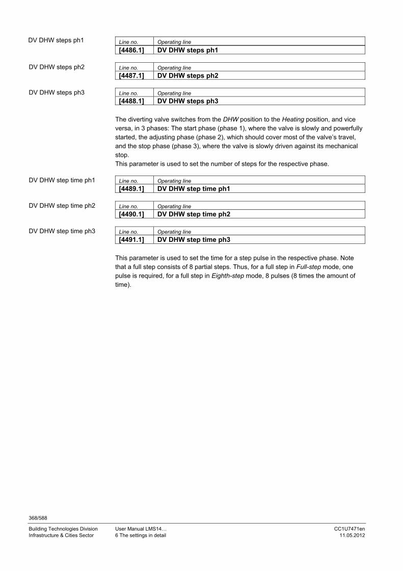
368/588
Building Technologies Division User Manual LMS14… CC1U7471en Infrastructure & Cities Sector 6 The settings in detail 11.05.2012
Line no. Operating line
[4486.1] DV DHW steps ph1
Line no. Operating line
[4487.1] DV DHW steps ph2
Line no. Operating line
[4488.1] DV DHW steps ph3 The diverting valve switches from the DHW position to the Heating position, and vice versa, in 3 phases: The start phase (phase 1), where the valve is slowly and powerfully started, the adjusting phase (phase 2), which should cover most of the valve’s travel, and the stop phase (phase 3), where the valve is slowly driven against its mechanical stop. This parameter is used to set the number of steps for the respective phase.
Line no. Operating line
[4489.1] DV DHW step time ph1
Line no. Operating line
[4490.1] DV DHW step time ph2
Line no. Operating line
[4491.1] DV DHW step time ph3 This parameter is used to set the time for a step pulse in the respective phase. Note that a full step consists of 8 partial steps. Thus, for a full step in Full-step mode, one pulse is required, for a full step in Eighth-step mode, 8 pulses (8 times the amount of time).
DV DHW steps ph1
DV DHW steps ph2
DV DHW steps ph3
DV DHW step time ph1
DV DHW step time ph2
DV DHW step time ph3

369/588
Building Technologies Division User Manual LMS14… CC1U7471en Infrastructure & Cities Sector 6 The settings in detail 11.05.2012
Line no. Operating line
[4483.1] DV DHW st length ph1 Full step
Half step
Quarter-step
Eighth-step
Line no. Operating line
[4484.1] DV DHW st length ph2 Full step
Half step
Quarter-step
Eighth-step
Line no. Operating line
[4485.1] DV DHW st length ph3 Full step
Half step
Quarter-step
Eighth-step This parameters are used to set the step size for one step pulse in the respective phase. Full step One step pulse causes the stepper motor to travel one full step. Note the time required per step pulse. Half step One step pulse causes the stepper motor to travel half a step. Note the time required per step pulse (2 pulses for one full step). Quarter-step One step pulse causes the stepper motor to travel one quarter of a step. Note the time required per step pulse (4 pulses for one full step). Eighth-step One step pulse causes the stepper motor to travel one eighth of a step. Note the time required per step pulse (8 pulses for one full step).
DV DHW st length ph1
DV DHW st length ph2
DV DHW st length ph3

370/588
Building Technologies Division User Manual LMS14… CC1U7471en Infrastructure & Cities Sector 6 The settings in detail 11.05.2012
6.22.5 Boiler
Line no. Operating line
5774 Ctrl boiler pump/DHW valve All requests Request HC1/DHW only
This parameter is for use with special hydraulic diagrams to define that boiler pump Q1 and diverting valve Q3 are only in charge of DHW heating and heating circuit 1, but not of heating circuits 2 and 3 and of external consumer circuits. All requests Hydraulically speaking, the diverting valve is used with all heat requests and switches between DHW mode and the other heat requests. The boiler pump runs whenever there is a request for heat. Request HC1/DHW only Hydraulically speaking, the diverting valve is only used with heating circuit 1 and DHW mode and switches between DHW mode and heating circuit 1. In the case of all other heat requests, the diverting valve (UV) and the boiler pump are not hydraulically involved; they go directly to the boiler.
6.22.6 Boiler pump The boiler pump is activated whenever the boiler is released or the burner is running.
Note! The boiler pump can also be activated via the following functions: Frost protection for the plant Boiler protection Chimney sweep (via release)/special operating modes Forced signals (storage tank recooling)
To give consideration to special hydraulic configurations, assignment of the boiler pump to heat requests can be changed. If the following parameter was set to On, a request for heat from heating circuits 2 and 3 would not lead to an activation of the boiler pump.
Ctrl boiler pump/ DHW valve

371/588
Building Technologies Division User Manual LMS14… CC1U7471en Infrastructure & Cities Sector 6 The settings in detail 11.05.2012
Basics of boiler pump Control of the boiler pump is performed based on the speed calculated for the DHW pump (charging pump Q3 or instantaneous water heater pump Q34) for DHW mode, or based on the highest speed calculated for the 3 heating circuit pumps for Heating mode only. The calculated pump speed for heating circuits 2 and 3 is evaluated only if these heating circuits also are hydraulically dependent on the position of the diverting valve (parameters Ctrl boiler pump/DHW valve (5774)). The speed of the boiler pump is fully adopted from the DHW or heating circuit pump. Hence, only the PWM limits of the respective DHW or heating circuit pump are valid. In that case, no consideration is given to the PWM limits of the boiler pump.
Note! This function is only used in connection with single-boiler plants. For cascaded systems, one of the other functions must be selected.
The function is selected via enumeration Demand of parameter Pump modulation (2320). Line no. Operating line 881 Starting speed 2320 Pump modulation 5101 Pump speed min 5530 Pump speed min 882 Pump speed min 5102 Pump speed max 5531 Pump speed max 885 Pump speed min OEM 5106 Pump speed min OEM 5535 Pump speed min OEM 886 Pump speed max OEM 5107 Pump speed max OEM 5536 Pump speed max OEM Line no. Operating line 8308 Boiler pump speed 8310 Boiler temp
Speed according to DHW pump/heating circuit pumps
Additional parameters
Info/diagnostics

372/588
Building Technologies Division User Manual LMS14… CC1U7471en Infrastructure & Cities Sector 6 The settings in detail 11.05.2012
Objective: The boiler shall be enabled to supply as much heat as possible to the storage tank. The boiler pump shall modulate its speed in a way that the current setpoint (DHW or buffer storage tank) is reached at the boiler flow. The boiler pump’s speed shall be increased within predefined limits until the burner reaches its upper capacity limit. For modulation of the boiler pump in DHW mode, the PWM limits of the DHW charging pump apply, in Heating mode, the PWM limits of the boiler pump. Speed control of the boiler pump reduces the boiler’s water throughput (pump speed) to such an extent that the required boiler flow temperature setpoint will be reached. For that, the setpoint fed to speed control is not the same as that forwarded to the LMS14...; the setpoint used for speed control is lower. This ensures that the pump’s speed is increased before the flow temperature setpoint is reached. This prevents the boiler from reaching its setpoint at reduced output only because the pump runs at a lower speed. In that case, only part of the boiler’s output would be used. The speed is calculated by a PID controller. At low boiler output (current output below 66%), the setpoint for speed control is reduced by an adjustable value. If the relative boiler output exceeds 66%, the setpoint for speed control is increased in such a way that the setpoint for speed calculation at 100% boiler output corresponds to the request for heat. The function is selected via enumeration Boiler setpoint of parameter Pump modulation (2320).
Setpoints
Speedsetpoint
10 K
7471d12e/0709 Figure 82: Boiler pump – Speed control depending on the boiler temperature setpoint
The diagram shows a setpoint reduction of 10 K. It can be parameterized.
Speed control depending on the boiler temperature setpoint

373/588
Building Technologies Division User Manual LMS14… CC1U7471en Infrastructure & Cities Sector 6 The settings in detail 11.05.2012
Line no. Operating line 2320 Pump modulation 2322 Pump speed min 2323 Pump speed max 2327 Pump speed min OEM 2328 Pump speed max OEM 2329 Pump setpoint reduction 5101 Pump speed min 5102 Pump speed max 5106 Pump speed min OEM 5107 Pump speed max OEM Line no. Operating line 8308 Boiler pump speed 8310 Boiler temp 8311 Boiler setpoint
Additional parameters
Info/diagnostics

374/588
Building Technologies Division User Manual LMS14… CC1U7471en Infrastructure & Cities Sector 6 The settings in detail 11.05.2012
The LMS14... keeps controlling the boiler’s output by maintaining the boiler temperature setpoint. Pump speed control ensures control of the boiler pump speed such that the parameterized boiler temperature differential between boiler return and boiler flow is maintained. If the current boiler temperature increase exceeds the nominal differential, the pump speed is increased or, otherwise, decreased. The pump’s speed is limited by the parameterized minimum and maximum speeds. In DHW heating mode, the boiler pump’s speed is not controlled to the parameterized nominal boiler temperature increase. The speed of the boiler pump in DHW heating mode is calculated based on the Demand function (see above). For all other operating modes – with the exception of DHW heating mode – following applies: If the boiler return temperature is not available (sensor defective or not configured), or if no valid boiler temperature increase is configured, the speed of the boiler pump is calculated based on the Boiler temperature setpoint function. The function is selected via enumeration Temp differential nominal of parameter Pump modulation (2320). Line no. Operating line 2317 Temp differential nominal 2320 Pump modulation 2322 Pump speed min 2323 Pump speed max 2324 Speed Xp 2325 Speed Tn 2326 Speed Tv 2327 Pump speed min OEM 2328 Pump speed max OEM Line no. Operating line 8308 Boiler pump speed 8310 Boiler temp 8314 Boiler return temp
Control according to boiler temperature differential
Additional parameters
Info/diagnostics

375/588
Building Technologies Division User Manual LMS14… CC1U7471en Infrastructure & Cities Sector 6 The settings in detail 11.05.2012
This function is suited for both single-boiler plants and cascaded systems with or without pressureless header. If the burner is operated at low output, the boiler pump should also run at low speed. And if the boiler operates at high output, the boiler pump should run at high speed. The boiler pump’s speed is calculated based on the current boiler output. The boiler pump is operated at minimum speed up to a certain boiler output that can be parameterized (minimum output). Above another boiler output that can be parameterized (maximum output), the boiler pump is operated at maximum speed. Between minimum output (Ynmin) and maximum output, the pump’s speed is continually increased. For calculation of the pump speed, a filtered boiler output value is used. In the case the boiler’s output changes abruptly, it may therefore take up to 3 minutes for the pump speed to adapt to the new burner output. The function is selected via enumeration Burner output of parameter Pump modulation (2320). Line no. Operating line 2320 Pump modulation 2322 Pump speed min 2323 Pump speed max 2327 Pump speed min OEM 2328 Pump speed max OEM 2334 Output at pump speed min 2335 Output at pump speed max Line no. Operating line 8308 Boiler pump speed 8323 Fan speed
Modulation depending on boiler output
Additional parameters
Info/diagnostics

376/588
Building Technologies Division User Manual LMS14… CC1U7471en Infrastructure & Cities Sector 6 The settings in detail 11.05.2012
The PWM limits for pumps at the Heating engineer level are either relative or absolute. The selection is made via factory settings at the Heating engineer level. With absolute PWM limits, the setting range for the heating engineer is restricted by the OEM limits. The heating engineer can vary the minimum speed only above the minimum set by the OEM, and the maximum speed only below the maximum set by the OEM. With relative PWM limits, the speed range restricted by the OEM forms the basis for the setting range available to the heating engineer, which always reaches from 0% to 100%. This means that 0% corresponds to the OEM’s minimum value, and 100% to the OEM’s maximum value. Values between 0% and 100% naturally restrict the speed range limited by the OEM. Here, the values displayed for the pump speed are not identical with the control value for the pump. For speed limitation, a set of 6 parameters are available for every pump. It consists of the absolute min./max. values at the Heating engineer level, the relative min./max. values at the Heating engineer level, and the min./max. values at the OEM level. The parameters for the relative speed limits are not interlocked with the limits at the OEM level. There is only a reciprocal limitation of min. and max. value active (min. cannot be set above max., and vice versa).
Note! The setting limits at the OEM level are also restricted by the parameters for the absolute speed limits at the Heating engineer level. This means that the upper speed limit at the OEM level cannot be set below the max. value at the Heating engineer level. When using the relative PWM limits, it is therefore recommended to set the lower and upper speed limit at the Heating engineer level to 50%. This means that the range from 0% to 50% is available for the lower OEM limit, and the range from 50% to 100% for the upper OEM limit.
6.22.7 Solar
Line no. Operating line
5840 Solar controlling element Charging pump Diverting valve
In place of a collector pump and diverting valves for integrating the storage tanks, the solar plant can also be operated with charging pumps. Charging pump When using a charging pump, all heat exchangers can be used simultaneously. Parallel or alternative operation is possible. Diverting valve When using a diverting valve, it is only one heat exchanger that can be used at a time. Only alternative operation is possible.
Line no. Operating line
5841 External solar exchanger Commonly DHW storage tank Buffer storage tank
In the case of solar plant diagrams with 2 storage tanks, it must be selected whether there is an external heat exchanger for both the DHW and the buffer storage tank or for only one of them.
Relative and absolute PWM limits
Solar controlling element
External solar exchanger

377/588
Building Technologies Division User Manual LMS14… CC1U7471en Infrastructure & Cities Sector 6 The settings in detail 11.05.2012
6.22.8 Combi storage tanks
Line no. Operating line
5870 Combi storage tank No Yes
Functions specific to combi storage tanks are activated via this setting. For example, the electric immersion heater installed in the buffer storage tank can be used for both space heating and DHW heating.
No No combi storage tank available. Yes Combi storage tank available.
Note! In the case of a combi storage tank, electric immersion heater K16 is switched on to satisfy both space heating and DHW requests.
Combi storage tank

378/588
Building Technologies Division User Manual LMS14… CC1U7471en Infrastructure & Cities Sector 6 The settings in detail 11.05.2012
6.22.9 Relay outputs QX
Note! Output QX4 is a stepper motor output and is referred to as WX1 in the illustration of chapter Terminals of LMS14… complete (Basic).
Line no. Operating line
5890 5891 5892
Relay output QX1, 2, 3 None
Circulating pump Q4
El imm heater DHW K6
Collector pump Q5
Cons circuit pump VK1 Q15
Boiler pump Q1
Bypass pump Q12
Alarm output K10
2nd pump speed HC1 Q21
2nd pump speed HC2 Q22
2nd pump speed HC3 Q23
Heat circuit pump HC3 Q20
Cons circuit pump VK2 Q18
System pump Q14
Heat gen shutoff valve Y4
Solid fuel boiler pump Q10
Time program 5 K13
Buffer return valve Y15
Solar pump ext exch K9
Solar ctrl elem buffer K8
Solar ctrl elem swi pool K18
Swimming pool pump Q19
Cascade pump Q25
St tank transfer pump Q11
DHW mixing pump Q35
DHW interm circ pump Q33
Heat request K27
Refrigeration request K28
Heat circuit pump HC1 Q2
Heat circuit pump HC2 Q6
DHW ctrl elem Q3
Instant heater ctrl elem Q34
Water filling K34
2nd boiler pump speed Q27
Status output K35
Status information K36
Flue gas damper K37
Fan shutdown K38 The relay output settings assign the appropriate functions. None Relay output with no function. Circulating pump Q4 The connected pump serves as a DHW circulating pump. Operation of the pump can be scheduled as required on operating page DHW, operating line Circulating pump release (1660).
Relay output QX1, 2, 3

379/588
Building Technologies Division User Manual LMS14… CC1U7471en Infrastructure & Cities Sector 6 The settings in detail 11.05.2012
El imm heater DHW K6 Using the connected electric immersion heater, the DHW can be heated up according to DHW storage tank (El imm heater optg mode (5060), El immersion heater release (5061) and El immersion heater control (5062)).
Warning! The electric immersion heater must be equipped with a safety limit thermostat!
Note! El imm heater optg mode (5060) of the electric immersion heater’s operating mode must be appropriately set.
Collector pump Q5 When using a solar collector, a circulating pump for the collector circuit is required. Cons circuit pump VK1 Q15 Consumer circuit pump VK1 can be used for an additional consumer. Together with an external request for heat at input H and configuration Consumer request VK1, an air heater or a similar piece of equipment can be operated. Boiler pump Q1 The connected pump is used for circulating the boiler water. Bypass pump Q12 Function is not implemented. Alarm output K10 In the case of an error message, this output is switched with LPB priority ≥ 6, provided the alarm output is selected for use with one of the relay outputs QX1…3. The alarm relay signals faults, should they occur. In the event of fault, the relay’s contact closes after an adjustable Alarm delay (6612). When the fault is corrected, that is, when the fault status is no longer present, the relay is deenergized with no delay.
Note! If the fault cannot immediately be corrected, it is still possible to reset the alarm relay. This is made on operating page Faults.

380/588
Building Technologies Division User Manual LMS14… CC1U7471en Infrastructure & Cities Sector 6 The settings in detail 11.05.2012
2nd pump speed HC1 Q21 Pump speed 2 for heating circuit 1 is activated. 2nd pump speed HC2 Q22 Pump speed 2 for heating circuit 2 is activated. 2nd pump speed HC3 Q23 Pump speed 2 for heating circuit 3 is activated. Heat circuit pump HC3 Q20 Pump heating circuit HC3 is activated. Cons circuit pump VK2 Q18 Consumer circuit pump VK2 can be used for an additional consumer. Together with an external request for heat at input H and configuration Consumer request VK2, an air heater or similar piece of equipment can be operated. System pump Q14 The connected pump serves as a system pump, which can be used to supply heat to additional consumers. It is put into operation when there is a request for heat from one of the consumers. If there is no request, the pump is deactivated on completion of the overrun time. Heat gen shutoff valve Y4 If the buffer storage tank holds a sufficient amount of heat, the consumers can draw their heat from it, and the heat sources need not be put into operation. The automatic heat generation lock locks the heat sources and hydraulically disconnects them from the rest of the plant via heat source shutoff valve Y4. This means that the consumers draw their heat from the buffer storage tank and wrong circulation through the heat sources will be prevented. Solid fuel boiler pump Q10 For the connection of a solid fuel boiler, a circulating pump for the boiler circuit is required. Time program 5 K13 The relay is controlled according to the settings made in Time program 5. Buffer return valve Y15 This valve must be configured for return temperature increase/decrease or partial charging of the buffer storage tank. Solar pump ext exch K9 For the external heat exchanger, Solar pump ext exch K9 must be set at the multifunctional relay output QX or PWM output P1. If both a DHW and a buffer storage tank are available, External solar exchanger (5841) must also be set. Solar ctrl elem buffer K8 If several heat exchangers are used, the buffer storage tank must be set at the respective relay output and, in addition, the type of solar controlling element must be defined on Solar controlling element (5840). Solar ctrl elem swi pool K18 If several heat exchangers are used, the swimming pool must be set at the respective relay output and, in addition, the type of solar controlling element must be defined on Solar controlling element (5840).

381/588
Building Technologies Division User Manual LMS14… CC1U7471en Infrastructure & Cities Sector 6 The settings in detail 11.05.2012
Swimming pool pump Q19 Using the swimming pool pump, the swimming pool can also be heated by the heat source. Cascade pump Q25 Common boiler pump for all boilers in a cascaded system. St tank transfer pump Q11 If the temperature level of the buffer storage tank is high enough, the DHW storage tank can be charged by the buffer. This transfer can be made via storage tank transfer pump Q11. DHW mixing pump Q35 Separate pump for storage tank circulation during the time the Legionella function is active. DHW intern circ pump Q33 Charging pump with DHW storage tank using an external heat exchanger. Heat request K27 Contact makes to inform an external heat source that a request for heat is pending.
Note! In the case of compensation variants without room thermostat, a minimum request for heat may be constantly present – and thus a request to the external heat source.
Note! With cascade operation, this function can only be used via the master.
Refrigeration request K28 When cooling circuit 1 sends a refrigeration request, output Refrigeration request (K28) is activated. Heat circuit pump HC1 Q2 Pump heating circuit HC1 is activated. Heat circuit pump HC2 Q6 Pump heating circuit HC2 is activated. DHW ctrl elem Q3 Controlling element for DHW storage tank. Instant heater ctrl elem Q34 Controlling element for instantaneous water heater. Water filling K34 Function is not implemented. 2nd pump speed boiler Q27 Speed 2 of the boiler pump is activated.

382/588
Building Technologies Division User Manual LMS14… CC1U7471en Infrastructure & Cities Sector 6 The settings in detail 11.05.2012
Status output K35 The status output is activated:
When, from standby, a request from the controller to the burner control is active
When startup is initiated in the phase In the operation phase When a request from the controller is pending
When one of the above mentioned preconditions is fulfilled, the status output is set, even if start prevention – caused by an open gas pressure switch – is demanded. In all other cases, the status output is deactivated. The status output is also used if power supply for an additional gas valve (e.g. for liquefied gas in an external tank) is required. With these types of application, output K35 remains activated if an open gas pressure switch causes start prevention, and the burner control quits start prevention again when gas pressure returns (gas pressure switch closes) and a heat request is pending. If the gas pressure switch switches off during operation, output K35 is only deactivated during postpurging. If the request for heat continues to exist and the burner control goes to start prevention, output K35 is activated again to remain activated. Status information K36 The output is switched when Operation phase (modulation) is active and when Status output is selected for one of the relay outputs QX1…3. Flue gas damper K37 Control of flue gas damper (refer to chapter Control of flue gas damper). Fan shutdown K38 Function Fan shutdown to turn off power when the fan is not needed.

383/588
Building Technologies Division User Manual LMS14… CC1U7471en Infrastructure & Cities Sector 6 The settings in detail 11.05.2012
Line no. Operating line
5894 Relay output QX4 None
Heat gen shutoff valve Y4
Buffer return valve Y15
Solar ctrl elem buffer K8
Solar ctrl elem swi pool K18
DHW ctrl elem Q3
Instant heater ctrl elem Q34 The relay output settings assign the appropriate functions. None Relay output with no function. Heat gen shutoff valve Y4 If the buffer storage tank holds a sufficient amount of heat, the consumers can draw their heat from it, and the heat sources need not be put into operation. Automatic heat generation lock locks the heat sources and hydraulically disconnects them from the rest of the plant via heat source shutoff valve Y4. This means that the consumers draw their heat from the buffer storage tank and wrong circulation through the heat sources will be prevented. Buffer return valve Y15 This valve must be configured for return temperature increase/decrease or partial charging of the buffer storage tank. Solar ctrl elem buffer K8 If several heat exchangers are used, the buffer storage tank must be set at the respective relay output and, in addition, the type of solar controlling element must be defined on Solar controlling element (5840). Solar ctrl elem swi pool K18 If several heat exchangers are used, the swimming pool must be set at the respective relay output and, in addition, the type of solar controlling element must be defined on Solar controlling element (5840). DHW ctrl elem Q3 Controlling element for DHW storage tank. Instant heater ctrl elem Q34 Controlling element for instantaneous water heater.
Stepper motor output QX4 (WX1)
Relay output QX4

384/588
Building Technologies Division User Manual LMS14… CC1U7471en Infrastructure & Cities Sector 6 The settings in detail 11.05.2012
6.22.10 Sensor inputs BX
Line no. Operating line
5930 5931 5932
Sensor input BX1, 2, 3, 4 None DHW sensor B31 Collector sensor B6 DHW circulation sensor B39 Buffer sensor B4 Buffer sensor B41 Flue gas temp sensor B8 Common flow sensor B10 Solid fuel boiler sensor B22 DHW charging sensor B36 Buffer sensor B42 Common return sensor B73 Cascade return sensor B70 Swimming pool sensor B13 Solar flow sensor B63 Solar return sensor B64 Primary exch sensor B26
The sensor input settings assign the appropriate functions.
Note! Sensor input BX4 is ready assigned to sensor B7. Reading in sensor B7 is safety-related.
None Sensor input with no function. DHW sensor B31 DHW storage tank sensor at the bottom. Collector sensor B6 This sensor is required for the Solar function. DHW circulation sensor B39 DHW circulation sensor/standby sensor. Buffer sensor B4 Buffer storage tank sensor at the top. Buffer sensor B41 Buffer storage tank sensor at the bottom. Flue gas temp sensor B8 This sensor is required for flue gas supervision. Common flow sensor B10 This sensor is required for the common flow.
Sensor input BX

385/588
Building Technologies Division User Manual LMS14… CC1U7471en Infrastructure & Cities Sector 6 The settings in detail 11.05.2012
Solid fuel boiler sensor B22 This sensor is required for the solid fuel boiler. DHW charging sensor B36 This sensor is required for DHW charging. Buffer sensor B42 Third buffer storage tank sensor (in the middle). Common return sensor B73 This sensor is required for the common return. Cascade return sensor B70 This sensor is required for the cascade return. Swimming pool sensor B13 This sensor is required for the swimming pool. Solar flow sensor B63 Solar flow sensor for yield measurement. Solar return sensor B64 Solar return sensor for yield measurement. Primary exch sensor B26 Customer-specific sensor.

386/588
Building Technologies Division User Manual LMS14… CC1U7471en Infrastructure & Cities Sector 6 The settings in detail 11.05.2012
6.22.11 Inputs H1/H3/H4/H5/H6/H7
Warning! If, with the safety-related GP configuration (9612), function Gas pressure switch is selected, Function input H6 (6008) only allows the selection of None. Function input H6 (6008) is evaluated only when the safety-related GP configuration (9612) is set to GP not connected. If, then, Function input H6 (6008) is used to select function Gas pressure switch, the latter is not safety-related.
Warning! If, for input H7 with the safety-related LP configuration (9611), a safety-related function Air pressure switch is parameterized, Function input H7 (6011) only allows the selection of None.
Line no. ¹) Operating line
5950 5960 5970 5977 6008 6011
Function of input Hx None
Optg mode change HCs+DHW
Optg mode changeover DHW
Optg mode changeover HCs
Optg mode changeover HC1
Optg mode changeover HC2
Optg mode changeover HC3
Heat generation lock
Error/alarm message
Consumer request VK1
Consumer request VK2
Release swi pool generator
Excess heat discharge
Release swi pool solar
Operating level DHW
Operating level HC1
Operating level HC2
Operating level HC3
Room thermostat HC1
Room thermostat HC2
Room thermostat HC3
DHW flow switch
DHW thermostat
Pulse count
Checkb sign flue gas damper
Start prevention
Boiler flow switch
Boiler pressure switch
Consumer request VK1 10V
Consumer request VK2 10V
Pressure measurement 10V
Output request 10V
Function of input H1, H3, H4, H5, H6, H7

387/588
Building Technologies Division User Manual LMS14… CC1U7471en Infrastructure & Cities Sector 6 The settings in detail 11.05.2012
Function H1 H3 H4 H5 H6 H7 0 None 1 Optg mode changeover HCs+DHW 2 Optg mode changeover DHW 3 Optg mode changeover HCs 4 Optg mode changeover HC1 5 Optg mode changeover HC2 6 Optg mode changeover HC3 7 Heat generation lock 8 Error/alarm message 9 Consumer request VK1 10 Consumer request VK2 11 Release swi'pool consumer 12 Excess heat discharge 13 Release swi pool solar 14 Operating level DHW 15 Operating level HC1 16 Operating level HC2 17 Operating level HC3 18 Room thermostat HC1 19 Room thermostat HC2 20 Room thermostat HC3 21 DHW flow switch 22 DHW thermostat 24 Pulse count 28 Checkback signal flue gas damper 29 Start prevention 31 Boiler flow switch 32 Boiler pressure switch 34 Gas pressure switch 50 Flow measurement Hz 51 Consumer request VK1 10V
52 Consumer request VK2 10V
54 Pressure measurement 10V
58 Output request 10V
Assignment of line numbers to the individual parameters of inputs Hx:
Function Type U1 F1 U2 F2
H1 5950 5951 5953 5954 5955 5956
H3 5960 5961 5963 5964 5965 5966
H4 ¹) 5970 5971 5973 5974 5975 5976
H5 5977 5978 --- --- --- ---
H6 6008 6009 --- --- --- ---
H7 6011 6012 --- --- --- ---
¹) At H4, a frequency value is to be entered for U1 and U2 – not a voltage value

388/588
Building Technologies Division User Manual LMS14… CC1U7471en Infrastructure & Cities Sector 6 The settings in detail 11.05.2012
None Input with no function. Optg mode changeover Heating circuit:
The operating modes of the heating circuits are switched to Protection mode via input Hx (e.g. using a remote telephone switch) (Optg mode changeover (900/1200/1500))
DHW: DHW heating is locked only when using setting HCs + DHW or DHW.
Heat generation lock The heat source is locked via terminals Hx. All requests for heat from the heating circuits and from DHW are ignored. Frost protection for the boiler is maintained.
Note! The Chimney sweep function can be activated although heat generation lock is active.
Error/alarm message Input H1 generates a controller-internal error message. If the Alarm output (Relay output QX2 (5891), Relay output QX3 (5892), Relay output QX4 (5894)) is appropriately configured, the error message is forwarded or displayed by an additional contact (e.g. an external lamp or horn). Consumer request VKx The adjusted flow temperature setpoint is activated via the terminals (e.g. air heater function for a warm air curtain).
Note! The setpoint is to be set via Flow temp setp cons request (1859/1909).
Release swi pool heat source This function enables swimming pool heating to be released by the heat source.
Note! The setpoint is to be set via Flow temp setp swi pool (1959).
Excess heat discharge Active dissipation of excess heat enables an external heat source to force consumers (heating circuit, DHW storage tank, Hx pump) to draw excess heat by delivering a forced signal. Parameter Excess heat draw (e.g. (861) for heating circuit 1) can be used to determine for every consumer whether or not it shall take account of the forced signal and, hence, whether or not it shall draw heat. Local effect:
When using LPB device address 0 or >1, excess heat discharge only acts on the local consumers connected to the controller.
Central effect (LPB): When using LPB device address = 1, excess heat discharge also acts on the consumers connected to the other controllers in the same segment. The distribution of excess heat from segment 0 across other segments of the system is not possible.

389/588
Building Technologies Division User Manual LMS14… CC1U7471en Infrastructure & Cities Sector 6 The settings in detail 11.05.2012
Release swi pool solar This function can be used to enable solar heating of the swimming pool from externally (e.g. with a manual switch), or to define solar charging priority against the storage tanks. Configuration: Set function Input Hx to Release swimming pool. For details, refer to Charging priority solar (2065). Operating level HCs/DHW The operating level can be set via the contact in place of using the internal time program (external time program). Room thermostat HCx The input can be used to generate a room thermostat request for the selected heating circuit. If several inputs Hx are configured for the room thermostat to be used with the same heating circuit, only input Hx with the highest number is used. The other inputs are not taken into consideration (no configuration error). Order of inputs Hx with the same room thermostat configuration: H7, H6, H5, H4, H3, H2-EM3, H2-EM2, H2-EM1, H1. DHW flow switch Here, the flow switch of the instantaneous water heater is connected. DHW thermostat Here, the DHW storage tank thermostat is connected. In addition, DHW sensor (5730) on the Configuration menu is to be set to Thermostat and no connection is allowed at input B3/B38. Pulse count Low-frequency pulses (e.g. for flow measurement) can be acquired by querying the input. Feedback flue gas damper This feedback is required for function Control of flue gas damper (refer to chapter Control of flue gas damper. Start prevention Function Start prevention is not yet implemented. If this function is configured to an input Hx, configuration error 152 is displayed.

390/588
Building Technologies Division User Manual LMS14… CC1U7471en Infrastructure & Cities Sector 6 The settings in detail 11.05.2012
Boiler flow switch The contacts of the boiler flow switch make when there is flow, or sufficient flow, through the boiler’s heat exchanger. If the contacts do not make, startup is prevented.
Warning! If the function is activated simultaneously at several inputs, it automatically
acts on the input with the highest number. Example: If the boiler flow switch is activated simultaneously at inputs H1 and H3, it only becomes active at H3 (no configuration error)
With the BwDl2 instantaneous water heater system, the boiler flow switch is not checked
Boiler pressure switch When the contacts of the pressure switch close, burner control startup and control of the pumps are immediately released. When the contacts open, start prevention or lockout is triggered.
Warning! If the function is activated simultaneously at several inputs, it automatically acts on the input with the highest number. Example: If the boiler pressure switch is activated simultaneously at inputs H1 and H3, it only becomes active at H3 (no configuration error).
Gas pressure switch The gas pressure switch responds when the gas pressure is too low. When it responds, the LMS14... always goes to the Start prevention phase. If the burner is in operation when the gas pressure switch responds, safety shutdown is triggered, followed by a change to the Start prevention phase. The LMS14... is again ready to operate when the gas pressure switch no longer indicates low gas pressure. The system behaves differently when the gas pressure switch responds during the safety time (establishment of flame). Here too, safety shutdown is triggered first, followed by a change to the Start prevention phase. If the gas pressure switch responds several times during the safety time, startup will be locked for 2 hours. When this time has elapsed, the LMS14... is again ready to operate, provided the gas pressure switch no longer indicates low gas pressure. The number of times the gas pressure switch may respond during the safety time until startup is locked depends on parameter RepCounter flame TSA [3633.1]. If this parameter is set to 1, startup lock is activated the first time the gas pressure switch responds during the safety time. If this parameter is set to 3, the unit is again ready to operate after the first and second time the gas pressure switch responds during the safety time, provided the gas pressure switch no longer indicates low gas pressure. If the gas pressure switch responds a third time during the safety time, the 2-hour startup lock takes effect.

391/588
Building Technologies Division User Manual LMS14… CC1U7471en Infrastructure & Cities Sector 6 The settings in detail 11.05.2012
Warning! If, with the safety-related GP configuration (9612), function Gas pressure switch is selected, Function input H6 (6008) only allows the selection of None. Function input H6 (6008) is evaluated only when the safety-related GP configuration (9612) is set to GP not connected. If, then, Function input H6 (6008) is used to select function Gas pressure switch, the latter is not safety-related. In that case, function Gas pressure switch is active as a non-safety-related function because it can be activated and deactivated from a non-safety-related operating section. Also refer to chapters Configuration and Program sequence of burner control (function).
Flow measurement Hz (frequency measurement) Here, a flow sensor can be connected, which indicates the flow rate in the form of a frequency value. Consumer request VKx 10V The heat source receives a voltage signal (DC 0...10 V) as the preselected output. A linear characteristic converts the applied voltage to a heat request. This linear characteristic is defined with the help of 2 fixed points (voltage value 1/function value 1, and voltage value 2/function value 2). The function value’s resolution is 0.1 °C. This means that the function value to be parameterized for a setpoint of 80 °C, for example, is 800. The request becomes active when – via the characteristic – the applied voltage leads to a flow temperature setpoint of at least 6 °C. The request for heat remains active as long as the applied voltage demands a flow temperature setpoint of at least 4 °C. The flow temperature setpoint is limited to the boiler’s maximum setpoint (Setpoint max (2212)). In addition, the flow temperature setpoint is limited to the limit thermostat’s Cutout temp LT (2531) – minimum switch-off differential in Heating mode (Switching diff off min HCs (2455)) – 3 K. Pressure measurement DC 10 V The voltage signal present at input Hx is converted to a pressure value (linear conversion). The linear characteristic is defined by 2 fixed points (voltage value 1/function value 1, and voltage value 2/function value 2). Output request 10V The heat source receives a voltage signal (DC 0...10 V) as a heat request. A linear characteristic converts the applied voltage to an output request. This characteristic is defined with the help of 2 fixed points (voltage value 1/function value 1, and voltage value 2/function value 2). The function value’s resolution is 0.1%. This means that the function value to be parameterized for an output request of 50%, for example, is 500. The request becomes active when the applied voltage is a minimum of 200 mV. It remains active as long as the voltage at input H is a minimum of 150 mV. The switch-off point for the burner lies 3 K below the limit thermostat’s Cutout temp LT (2531). The burner’s switch-on point lies by the switch-on differential in Heating mode (Switching diff on HCs (2454)) below the switch-off point. There is no valid Boiler setpoint (8311).
Note! In the case of an externally preselected output, forced signals are sent to the consumers. As a result, the setpoints of all heating circuits (pump and mixing circuits) are set to their maximum.

392/588
Building Technologies Division User Manual LMS14… CC1U7471en Infrastructure & Cities Sector 6 The settings in detail 11.05.2012
The linear characteristic is defined by 2 fixed points. The setting uses 2 pairs of parameters for function value and voltage value (F1/U1 and F2/U2). Example of 2 different sensor characteristics:
1000 Hz max
U2 =850 Hz U2 =600 Hz U1 = 50 Hz
2.0 l/min
8.0 l/min
10.0 l/min
U1 = 1Hz
Frequency Hx [Hz]
Wateroutlet[l/min]
Function value
F2 = 100
F2 = 80
F1 = 20
74
71
d08
e/0
20
9
Figure 83: Inputs Hx - Flow measurement Hz
Key
F1 Function value 1 F2 Function value 2 U1 Frequency value 1 U2 Frequency value 2
Line no. Operating line
7862 Frequency H4 Flow detection DHW (DHW flow switch):
With instantaneous water heater systems, the flow entering the cold water inlet can be measured with a flow sensor. A DHW request is identified when the measured flow rate satisfies the following condition: DHW flow > threshold Tww-FlowSwitch A DHW request is not identified when the measured flow rate satisfies the following condition: DHW flow > threshold Tww-FlowSwitch – switching diff.Tww-FlowSwitch
Line no. Operating line
5444 Threshold flow detection 5445 Switching diff flow detection
Line no. Operating line
8860 DHW flow
Frequency value 1 Function value 1 Frequency value 2 Function value 2
Info/diagnostics
Additional parameters
Info/diagnostics

393/588
Building Technologies Division User Manual LMS14… CC1U7471en Infrastructure & Cities Sector 6 The settings in detail 11.05.2012
Line no. ¹) Operating line
5951 5961 5971 5978 6009 6012
Contact type Hx NC NO
The type of contact of Hx can be selected (NO or NC).
Parameters Type of contact Hx
Contact state at terminal Hx
Functional state/impact
Normally open contact (NO) Open Not active Closed Active Normally closed contact (NC) Open Active Closed Not active NC The contact is normally closed and must open to activate the selected function. NO The contact is normally open and must close to activate the selected function.
Contact type H1, H3, H4, H5, H6, H7

394/588
Building Technologies Division User Manual LMS14… CC1U7471en Infrastructure & Cities Sector 6 The settings in detail 11.05.2012
Line no. ¹) Operating line
5953 Voltage value 1 H1
Line no. ¹) Operating line
5954 Function value 1 H1
Line no. ¹) Operating line
5955 Voltage value 2 H1
Line no. ¹) Operating line
5956 Function value 2 H1
Line no. ¹) Operating line
5963 Voltage value 1 H3
Line no. ¹) Operating line
5964 Function value 1 H3
Line no. ¹) Operating line
5965 Voltage value 2 H3
Line no. ¹) Operating line
5966 Function value 2 H3
Line no. ¹) Operating line
5973 Frequency value 1 H4
Line no. ¹) Operating line
5974 Function value 1 H4
Line no. ¹) Operating line
5975 Frequency value 2 H4
Line no. ¹) Operating line
5976 Function value 2 H4
Voltage value 1 H1
Function value 1 H1
Voltage value 2 H1
Function value 2 H1
Voltage value 1 H3
Function value 1 H3
Voltage value 2 H3
Function value 2 H3
Frequency value 1 H4
Function value 1 H4
Frequency value 2 H4
Function value 2 H4

395/588
Building Technologies Division User Manual LMS14… CC1U7471en Infrastructure & Cities Sector 6 The settings in detail 11.05.2012
The linear characteristic is defined by 2 fixed points. The setting uses 2 pairs of parameters for function value and voltage value (F1/U1 and F2/U2). At input H4 (frequency input), a frequency value is assigned to the function value – and not a voltage value. Example of heat request DC 10 V
Flow temperature setpoint [°C]
Voltage at Hx
F2 = 80
U2 = 10 VU1 = 0 V
F1 = 0
0.15 V
F2 = 60
74
71
d0
9e/0
111
Figure 84: Inputs Hx – heat request
Key
F1 Function value 1
F2 Function value 2
U1 Frequency value 1
U2 Frequency value 2
If the input signal drops below the limit value of 0.15 V, the request for heat becomes invalid, which means it has no impact.
The function value to be set is calculated as follows: Function value = pressure value [bar]/0.1 bar Example of pressure measurement DC 10 V:
U2 = 3.5 V
4 bar
0
F2 = 40
2 bar
1 bar
U1 = 0.5 V
F2 = 20
F2 = 10
F1 = 0
74
71
d10
e/1
21
0
Pressure value [bar]
Voltage at Hx
Figure 85: Inputs Hx – pressure measurement
Key
F1 Function value 1
F2 Function value 2
U1 Frequency value 1
U2 Frequency value 2

396/588
Building Technologies Division User Manual LMS14… CC1U7471en Infrastructure & Cities Sector 6 The settings in detail 11.05.2012
6.22.12 Extension modules
Caution! Under the most unfavorable conditions, the signals from the extension modules to the LMS14..., and vice versa, may take up to 40 seconds to be refreshed via the BSB. This can lead to functional restrictions and detrimental effects on the limit thermostat functions. For such functions, use BX1, BX2, BX3, BX4/QX1, QX2, QX3, QX4 (only valves) /P1/H1, H3, H4, H5, H6 or H7.
Note! Sensor input BX4 is firmly assigned to sensor B7.
Line no. Operating line
6020 6021 6022
Function extension module x None
Multifunctional
Heating circuit 1
Heating circuit 2
Heating circuit 3
Return temp controller
Solar DHW
Prim contr/system pump None Function is deactivated. Multifunctional The choice of functions that can be assigned to the multifunctional inputs/outputs appear as … Relay output QX21 module 1 (6030), Relay output QX22 module 1 (6031), Relay output QX23 module 1 (6032), Relay output QX21 module 2 (6033), Relay output QX22 module 2 (6034), Relay output QX23 module 2 (6035), Relay output QX21 module 3 (6036), Relay output QX22 module 3 (6037), Relay output QX23 module 3 (6038), Sensor input BX21 module 1 (6040), Sensor input BX22 module 1 (6041), Sensor input BX21 module 2 (6042), Sensor input BX22 module 2 (6043), Sensor input BX21 module 3 (6044), and Sensor input BX22 module 3 (6045). Heating circuit 1 For this application, the respective settings of operating page Heating circuit 1 can be adapted. Heating circuit 2 For this application, the respective settings of operating page Heating circuit 2 can be adapted.
Function extension module 1, 2, 3

397/588
Building Technologies Division User Manual LMS14… CC1U7471en Infrastructure & Cities Sector 6 The settings in detail 11.05.2012
Heating circuit 3 For this application, the respective settings of operating page Heating circuit 3 can be adapted. Return temp controller This function is not implemented and leads to fault status message Parameterization. Solar DHW The relevant settings of operating page Solar can be matched to meet the requirements of this application. Prim contr/system pump For this application, the respective settings of operating page Primary controller/system pump can be adapted. Connections:
QX21 QX22 QX23 BX21 BX22 H2 Chapter
Multifunctional * * * * * * ---
Heating circuit 1 Y1 Y2 Q2 B1 * * ---
Heating circuit 2 Y5 Y6 Q6 B12 * * ¹)
Heating circuit 3 Y11 Y12 Q20 B14 * * ---
Return temperature controller
--- --- --- --- --- --- ---
Solar DHW * * Q5 B6 B31 * ¹)
Primary controller Y19 Y20 Q14 B15 * * ¹)
* Can be freely selected, refer to QX…/BX... extension module
¹) Refer to chapter Extra functions with extension module AVS75.390

398/588
Building Technologies Division User Manual LMS14… CC1U7471en Infrastructure & Cities Sector 6 The settings in detail 11.05.2012
6.22.13 EX extension modules 1/2/3
Line no. Operating line
6024 6026 6028
Funct input EX21 module x None Limit thermostat HC
Function Module 1 Module 2 Module 3 0 None 25 Limit thermostat HC
Note! Software versions 3.3, 3.4 and 3.5 of the operator terminal offer more functions than the number of functions available. The only functions that can be selected are None and Limit thermostat HC. With software version 3.6 and higher, these are the only 2 selectable functions.
None Input Hx with no function. Limit thermostat HC If the extension module is used for the heating circuit, an external limit thermostat (e.g. for floor heating) can be connected to input EX21 (AC 230 V). If the limit thermostat cuts out, … - the mixing valve is closed and the pump deactivated, - an error message Limit thermostat HCx is delivered, - status Limit thermostat cut out is generated. If the function of the extension module is set to Heating circuits 1…3 or Heating circuit/cooling circuit 1, and the function of input EX21 for the same module to Limit thermostat HC, the module gives consideration to the state at input EX21 in that case, for control of the relay outputs (pump and mixing valve opening/closing). Wiring example:
Figure 86: Extensions module – limit thermostat HC
Key
TW Limit thermostat
Funct input EX21 module 1, 2, 3

399/588
Building Technologies Division User Manual LMS14… CC1U7471en Infrastructure & Cities Sector 6 The settings in detail 11.05.2012
The state of 0 V is always interpreted as Limit thermostat cut out. The state at input EX21 is transmitted to the basic unit where it is evaluated for the generation of error messages. The input test also shows the state (0 V/230 V). Since inside the module input EX21 acts on the states of the relays, the limit thermostat continues to be active even if communication with the basic unit is interrupted. If the Limit thermostat function is not desired, the parameter settings for input EX21 must be appropriately changed.
Line no. Operating line
7950 Input EX21 module 1 7951 Input EX21 module 2 7952 Input EX21 module 3
Signal state: 0 V/230 V The current operating state can be verified on operating page Status. Start prevention This input can be used to prevent burner starts.
Note! Start prevention via this input is not safety-related.
Info/diagnostics
Operating state

400/588
Building Technologies Division User Manual LMS14… CC1U7471en Infrastructure & Cities Sector 6 The settings in detail 11.05.2012
6.22.14 QX extension modules 1/2/3
Caution! Under the most unfavorable conditions, the signals from the extension modules to the LMS14..., and vice versa, may take up to 40 seconds to be refreshed in the extension module via the BSB. This can lead to functional restrictions and detrimental effects on the limit thermostat functions. For such functions, use BX1, BX2, BX3 or BX4 (only valves).
Line no. Operating line
6030 6031 6032 6033 6034 6035 6036 6037 6038
Relay output QX21 module 1 Relay output QX22 module 1 Relay output QX23 module 1 Relay output QX21 module 2 Relay output QX22 module 2 Relay output QX23 module 2 Relay output QX21 module 3 Relay output QX22 module 3 Relay output QX23 module 3
None
Circulating pump Q4
El imm heater DHW K6
Collector pump Q5
Cons circuit pump VK1 Q15
Boiler pump Q1
Bypass pump Q12
Alarm output K10
2nd pump speed HC1 Q21
2nd pump speed HC2 Q22
2nd pump speed HC3 Q23
Heat circuit pump HC3 Q20
Cons circuit pump VK2 Q1
System pump Q14
Heat gen shutoff valve Y4
Solid fuel boiler pump Q10
Time program 5 K13
Buffer return valve Y15
Solar pump ext exch K9
Solar ctrl elem buffer K8
Solar ctrl elem swi pool K18
Swimming pool pump Q19
Cascade pump Q25
St tank transfer pump Q11
DHW mixing pump Q35
DHW interm circ pump Q33
Heat request K27
Refrigeration request K28
Heat circuit pump HC1 Q2
Heat circuit pump HC2 Q6
DHW ctrl elem Q3
Instant heater ctrl elem Q34
Water filling K34
2nd boiler pump speed Q27
Status output K35
Status information K36
Fan shutdown K38
Relay output QX... module 1, 2, 3

401/588
Building Technologies Division User Manual LMS14… CC1U7471en Infrastructure & Cities Sector 6 The settings in detail 11.05.2012
The relay output settings assign the appropriate functions. None Relay output with no function. Circulating pump Q4 The connected pump serves as a DHW circulating pump. Operation of the pump can be scheduled as required on operating page DHW, operating line Circulating pump release (1660). DHW El imm heater DHW K6 Using the connected electric immersion heater, the DHW can be heated according to operating page DHW storage tank (El imm heater optg mode (5060), El immersion heater release (5061) and El immersion heater control (5062)).
Warning! The electric immersion heater must be equipped with a safety limit thermostat!
Note! El imm heater optg mode (5060) of the electric immersion heater’s operating mode must be appropriately set.
Collector pump Q5 When using a solar collector, a circulating pump for the collector circuit is required. Cons circuit pump VK1 Q15 Consumer circuit pump VK1 can be used for an additional consumer. Together with an external request for heat at input H and configuration Consumer request VK1, an air heater or similar piece of equipment can be operated. Boiler pump Q1 The connected pump is used for circulating the boiler water. Bypass pump Q12 Function is not implemented. Alarm output K10 The alarm relay signals faults, should they occur. In the event of fault, the relay’s contact closes after an adjustable Alarm delay (6612). When the fault is corrected, that is, when the fault status is no longer present, the relay is deenergized with no delay.
Note! If the fault cannot immediately be corrected, it is still possible to reset the alarm relay. This is made on operating page Faults.
2nd pump speed HC1 Q21 Pump speed 2 for heating circuit 1 is activated. 2nd pump speed HC2 Q22 Pump speed 2 for heating circuit 2 is activated.

402/588
Building Technologies Division User Manual LMS14… CC1U7471en Infrastructure & Cities Sector 6 The settings in detail 11.05.2012
2nd pump speed HC3 Q23 Pump speed 2 for heating circuit 3 is activated. Heat circuit pump HC3 Q20 Pump heating circuit HC3 is activated. Cons circuit pump VK2 Q18 Consumer circuit pump VK2 can be used for an additional consumer. Together with an external request for heat at input H and configuration Consumer request VK2, an air heater or similar piece of equipment can be operated. System pump Q14 The connected pump serves as a system pump, which can be used to supply heat to additional consumers. It is put into operation when there is a request for heat from one of the consumers. If there is no request, the pump is deactivated on completion of the overrun time. Heat gen shutoff valve Y4 If the buffer storage tank holds a sufficient amount of heat, the consumers can draw their heat from it, and the heat sources need not be put into operation. The automatic heat generation lock locks the heat sources and hydraulically disconnects them from the rest of the plant via heat source shutoff valve Y4. This means that the consumers draw their heating energy from the buffer storage tank and wrong circulation through the heat sources will be prevented. Solid fuel boiler pump Q10 For the connection of a solid fuel boiler, a circulating pump for the boiler circuit is required. Time program 5 K13 The relay is controlled according to the settings made in Time program 5. Buffer return valve Y15 This valve must be configured for return temperature increase/decrease or partial charging of the buffer storage tank. Solar pump ext exch K9 For the external heat exchanger, solar pump external exchanger K9 must be set at the multifunctional relay output QX or PWM output P1. If a DHW and a buffer storage tank are available, External solar exchanger (5841) must be set also. Solar ctrl elem buffer K8 If several heat exchangers are used, the buffer storage tank must be set at the respective relay output and, in addition, the type of solar controlling element must be defined on Solar controlling element (5840). Solar ctrl elem swi pool K18 If several heat exchangers are used, the swimming pool must be set at the respective relay output and, in addition, the type of solar controlling element must be defined on Solar controlling element (5840). Swimming pool pump Q19 This function enables swimming pool heating to be released by the heat source. Cascade pump Q25 Common boiler pump for all boilers in a cascaded system.

403/588
Building Technologies Division User Manual LMS14… CC1U7471en Infrastructure & Cities Sector 6 The settings in detail 11.05.2012
St tank transfer pump Q11 If the temperature level of the buffer storage tank is high enough, the DHW storage tank can be charged by the buffer. This transfer can be made via storage tank transfer pump Q11. DHW mixing pump Q35 Separate pump for storage tank circulation during the time the Legionella function is active. DHW intern circ pump Q33 Charging pump with DHW storage tank using an external heat exchanger. Heat request K27 Contact makes to inform an external heat source that a request for heat is pending.
Note! With compensation variants without room thermostat, a minimum demand for heat may constantly be present, leading to a heat request to the external heat source.
Note! With cascade operation, this function can only be used via the master.
Refrigeration request K28 Output K28 is activated when there is a request for cooling energy in cooling circuit 1. Heat circuit pump HC1 Q2 Pump heating circuit HC1 is activated. Heat circuit pump HC2 Q6 Pump heating circuit HC2 is activated. DHW ctrl elem Q3 Controlling element for DHW storage tank. Instant heater ctrl elem Q34 Controlling element for instantaneous water heater. Water filling K34 Function is not implemented. 2nd boiler pump speed Q27 Speed 2 of the boiler pump is activated.

404/588
Building Technologies Division User Manual LMS14… CC1U7471en Infrastructure & Cities Sector 6 The settings in detail 11.05.2012
Status output K35 The status output is activated:
When, from standby, a request from the controller to the burner control is active
When startup is initiated in the phase In the operation phase When a request from the controller is pending
When one of the above mentioned preconditions is fulfilled, the status output is set, even if start prevention – caused by an open gas pressure switch – is demanded. In all other cases, the status output is deactivated. The status output is also used if power supply for an additional gas valve (e.g. for liquefied gas in an external tank) is required. With these types of application, output K35 remains activated if an open gas pressure switch causes start prevention, and the burner control quits start prevention again when gas pressure returns (gas pressure switch closes) and a heat request is pending. If the gas pressure switch switches off during operation, output K35 is only deactivated during postpurging. If the request for heat continues to exist and the burner control goes to start prevention, output K35 is activated again and remains activated. Status information K36 The output is switched when the Operation phase (modulation) is active and when the status output is selected for use with one of the relay outputs QX1…3. Fan shutdown K38 Function Fan shutdown to turn off power when the fan is not needed.

405/588
Building Technologies Division User Manual LMS14… CC1U7471en Infrastructure & Cities Sector 6 The settings in detail 11.05.2012
6.22.15 BX extension modules
Caution! Under the most unfavorable conditions, the signals from the extension modules to the LMS14..., and vice versa, may take up to 40 seconds to be refreshed in the LMS14… via the BSB. This can lead to functional restrictions and detrimental effects on the limit thermostat functions. For such functions, use BX1, BX2, BX3 or BX4.
Note! Sensor input BX4 is firmly assigned to sensor B7.
Line no. Operating line
6040 6041 6042 6043 6044 6045
Sensor input BX21 module 1 Sensor input BX22 module 1 Sensor input BX21 module 2 Sensor input BX22 module 2 Sensor input BX21 module 3 Sensor input BX22 module 3 None
DHW sensor B31
Collector sensor B6
DHW circulation sensor B39
Buffer sensor B4
Buffer sensor B41
Flue gas temp sensor B8
Common flow sensor B10
Solid fuel boiler sensor B22
DHW charging sensor B36
Buffer sensor B42
Common return sensor B73
Cascade return sensor B70
Swimming pool sensor B13
Solar flow sensor B63
Solar return sensor B64
Primary exch sensor B26 The relay output settings assign the appropriate functions. None Sensor input with no function. DHW sensor B31 DHW storage tank sensor at the bottom. Collector sensor B6 This sensor is required for the solar function. DHW circulation sensor B39 DHW circulation sensor/standby sensor. Buffer sensor B4 Buffer storage tank sensor at the top.
Sensor input BX... module 1, 2, 3

406/588
Building Technologies Division User Manual LMS14… CC1U7471en Infrastructure & Cities Sector 6 The settings in detail 11.05.2012
Buffer sensor B41 Buffer storage tank sensor at the bottom. Flue gas temperature sensor B8 This sensor is required for flue gas supervision. Common flow sensor B10 This sensor is required for the common flow. Solid fuel boiler sensor B22 This sensor is required for the solid fuel boiler. DHW charging sensor B36 This sensor is required for DHW charging. Buffer sensor B42 Third buffer storage tank sensor (in the middle). Common return sensor B73 This sensor is required for the common return. Cascade return sensor B70 This sensor is required for the cascade return. Swimming pool sensor B13 This sensor is required for the swimming pool. Solar flow sensor B63 Solar flow sensor for yield measurement. Solar return sensor B64 Solar return sensor for yield measurement. Primary exch sensor B26 Customer-specific sensor.

407/588
Building Technologies Division User Manual LMS14… CC1U7471en Infrastructure & Cities Sector 6 The settings in detail 11.05.2012
6.22.16 H2 extension modules 1/2/3
Warning! Under the most unfavorable conditions, the signals from the extension modules to the LMS14..., and vice versa, may take up to 40 seconds to be refreshed in the LMS14… via the BSB. This can lead to functional restrictions and detrimental effects on the limit thermostat functions. For such functions, use H1, H3, H4, H5, H6 or H7.
Line no. Operating line
6046 6054 6062
Function of input H2 module 1 Function of input H2 module 2 Function of input H2 module 3 None
Optg mode change HCs+DHW
Optg mode changeover DHW
Optg mode changeover HCs
Optg mode changeover HC1
Optg mode changeover HC2
Optg mode changeover HC3
Heat generation lock
Error/alarm message
Consumer request VK1
Consumer request VK2
Release swi pool generator
Excess heat discharge
Release swi pool solar
Operating level DHW
Operating level HC1
Operating level HC2
Operating level HC3
Room thermostat HC1
Room thermostat HC2
Room thermostat HC3
DHW flow switch
DHW thermostat
Limit thermostat HC
Start prevention
Boiler flow switch
Boiler pressure switch
Consumer request VK1 10V
Consumer request VK2 10V
Pressure measurement 10V
Output request 10V
Function of input H2 module 1, 2, 3

408/588
Building Technologies Division User Manual LMS14… CC1U7471en Infrastructure & Cities Sector 6 The settings in detail 11.05.2012
Assignment of line numbers to the parameter of inputs H2-EMx:
Function Type Value K U1 F1 U2 F2
H2 EM1 6046 6047 6048 6049 6050 6051 6052
H2 EM2 6054 6055 6056 6057 6058 6059 6060
H2 EM3 6062 6063 6064 6065 6066 6067 6068
Function H2 EMx 0 None 1 Optg mode change HCs + DHW 2 Optg mode changeover DHW 3 Optg mode changeover HCs 4 Optg mode changeover HC1 5 Optg mode changeover HC2 6 Optg mode changeover HC3 7 Heat generation lock 8 Error/alarm message 9 Consumer request VK1 10 Consumer request VK2 11 Release swi pool heat source 12 Excess heat discharge 13 Release swi pool solar 14 Operating level DHW 15 Operating level HC1 16 Operating level HC2 17 Operating level HC3 18 Room thermostat HC1 19 Room thermostat HC2 20 Room thermostat HC3 21 DHW flow switch 22 DHW thermostat 25 Limit thermostat HC 29 Start prevention 31 Boiler flow switch 32 Boiler pressure switch 51 Consumer request VK1 10 V 52 Consumer request VK2 10 V 54 Pressure measurement 10 V 58 Output request 10V
None Input Hx with no function. Optg mode changeover Heating circuit:
The operating modes of the heating circuits are changed to the parameterized operating mode (Optg mode changeover (900/1200/1500)) via terminals Hx (e.g. remote telephone switch).
DHW: DHW heating is locked only when using setting HCs + DHW or DHW.

409/588
Building Technologies Division User Manual LMS14… CC1U7471en Infrastructure & Cities Sector 6 The settings in detail 11.05.2012
Heat generation lock The heat source is locked via terminals Hx. All requests for heat from the heating circuits and DHW are ignored. Frost protection for the boiler is maintained.
Note! The Chimney sweep function can be activated although the heat generation lock is active.
Error/alarm message Input H1 generates a controller-internal error message. If the Alarm output (Relay output QX2 (5891), Relay output QX3 (5892), Relay output QX4 (5894)) is appropriately configured, the error message is forwarded or displayed by an additional contact (e.g. external lamp or horn). Consumer request VKx The adjusted flow temperature setpoint is activated via the terminals (e.g. an Air heater function for a warm air curtain).
Note! The setpoint is to be adjusted on Flow temp setp cons request (1859/1909)
Release swi pool heat source Q19 This function enables swimming pool heating to be released by the heat source.
Note! The setpoint is to be adjusted on Flow temp setp swi pool (1959)
Excess heat discharge Active dissipation of excess heat enables an external heat source to force consumers (heating circuit, DHW storage tank, Hx pump) to draw excess heat by delivering a forced signal. Parameter Excess heat draw (e.g. (861) for heating circuit 1) can be used to determine for every consumer whether or not it should take account of the forced signal and, hence, whether or not that consumer should participate in the dissipation of heat. Local effect:
When using LPB device address 0 or >1, excess heat discharge only acts on the local consumers connected to the controller.
Central effect (LPB): When using LPB device address = 1, excess heat discharge also acts on the consumers connected to the other controllers in the same segment. The distribution of excess heat from segment 0 across other segments of the system is not possible.
Release swi pool solar This function can be used to enable solar heating of the swimming pool from externally (e.g. via a manual switch) or to define solar charging priority against the storage tanks. Configuration: Set function Input Hx to Release swimming pool. For a description of function Solar charging priority, refer to Charging priority solar (2065). Operating level HCs/DHW The operating level can be set via the contact in place of using the internal time program (external time program).

410/588
Building Technologies Division User Manual LMS14… CC1U7471en Infrastructure & Cities Sector 6 The settings in detail 11.05.2012
Room thermostat HCx The input can be used to generate a room thermostat request for the selected heating circuit. If several inputs Hx are configured for the room thermostat to be used with the same heating circuit, only input Hx with the highest number is used. The other inputs are not taken into consideration (no configuration error). Order of inputs Hx with the same room thermostat configuration: H7, H6, H5, H4, H3, H2-EM3, H2-EM2, H2-EM1, H1. DHW flow switch Here, connect the flow switch of the instantaneous water heater. DHW thermostat Here, the DHW storage tank thermostat is connected. In addition, the DHW sensor (5730) of the Configuration menu is to be set to Thermostat and no connections are allowed at input B3/B38. Limit thermostat HC If the extension module for the heating circuit is used, an external limit thermostat (e.g. for floor heating) can be connected to input H2 (low-voltage). If the limit thermostat cuts out, … - the mixing valve is closed and the pump is deactivated, - an error message Limit thermostat HCx is delivered, - state Limit thermostat cut out is generated. If the function of the extension module is set to Heating circuits 1…3, and the function of input H2 for the same module to Limit thermostat HC, the module gives consideration to the state at input H2 in that case, for control of the relay outputs (pump and mixing valve opening/closing). Wiring example:
PE
N
N
PE
QX23
L
H2
M
230V
TW
Figure 87: H2 extension module When used as a limit thermostat input, the contact type of input H2 cannot be selected. The interpretation of Open is always Limit thermostat cut out. The state at input H2 is transmitted to the basic unit where it is evaluated for the generation of error messages. The input test also shows the state (Open/Closed).

411/588
Building Technologies Division User Manual LMS14… CC1U7471en Infrastructure & Cities Sector 6 The settings in detail 11.05.2012
Since input H2 inside the module acts on the states of the relays, the limit thermostat continues to be active even if communication with the basic unit is interrupted. If the Limit thermostat function is not desired, the parameter settings for input H2 must be appropriately changed.
Line no. Operating line
7846 Contact state H2 module 1 7849 Contact state H2 module 2 7852 Contact state H2 module 3
Signal states: Open/Closed. The current operating state can be verified on operating page Status. Start prevention Function Start prevention is not yet implemented. If this function was configured to an input Hx, configuration error 152 is displayed. Boiler flow switch The contacts of the boiler flow switch make when there is flow, or sufficient flow, through the boiler’s heat exchanger. If the contacts do not close, startup is prevented.
Warning! If the function is activated simultaneously at several inputs, it automatically
acts on the input with the highest number. Example: If the boiler flow switch is activated simultaneously at inputs H1 and H3, it only becomes active at H3 (no configuration error)
With the BwDl2 instantaneous water heater system, the boiler flow switch is not checked
Boiler pressure switch When the contacts of the pressure switch make, burner control startup and control of the pumps are immediately released. When the contacts break, start prevention or lockout is triggered.
Warning! If the function is activated simultaneously at several inputs, it automatically acts on the input with the highest number. Example: If the boiler pressure switch is activated simultaneously at inputs H1 and H3, it only becomes active at H3 (no configuration error).
Info/diagnostics
Operating state

412/588
Building Technologies Division User Manual LMS14… CC1U7471en Infrastructure & Cities Sector 6 The settings in detail 11.05.2012
Consumer request VKx 10V Application node External load x receives requests for heat in the form of voltage signals (DC 0...10 V). A linear characteristic converts the applied voltage to a heat request. This characteristic is defined via 2 fixed points (voltage value 1/function value 1, and voltage value 2/function value 2). The function value’s resolution is 0.1 °C. This means that the function value to be parameterized for a setpoint of 80 °C, for example, is 800. The request becomes active when – via the characteristic – the applied voltage leads to a flow temperature setpoint of at least 6 °C. The request for heat remains active as long as the applied voltage demands a flow temperature setpoint of at least 4 °C. The flow temperature setpoint is limited to the boiler’s maximum setpoint (Setpoint max (2212)). In addition, the flow temperature setpoint is limited to the Cutout temp LT (2531) – minimum switch-off differential in heating mode (Switching diff off min HCs (2455)) – 3 K. Pressure measurement DC 10 V The voltage signal at input Hx is converted to a pressure value (linear conversion). The linear characteristic is defined by 2 fixed points (voltage value 1/function value 1, and voltage value 2/function value 2). Output request 10V The heat source receives a voltage signal (DC 0...10 V) as a preselected output. A linear characteristic converts the applied voltage to an output request. This characteristic is defined via 2 fixed points (voltage value 1/function value 1, and voltage value 2/ function value 2). The function value’s resolution is 0.1%. This means that the function value to be parameterized for an output request of 50%, for example, is 500. The request becomes active when the applied voltage is a minimum of 200 mV. It remains active as long as the voltage at input H is a minimum of 150 mV. The switch-off point for the burner lies 3 K below the Cutout temp LT (2531). The burner’s switch-on point lies by the switch-on differential in heating mode (Switching diff on HCs (2454)) below the switch-off point. There is no valid Boiler setpoint (8311).
Note! In the case of an externally preselected output, forced signals are sent to the consumers. As a result, the setpoints of all heating circuits (pump and mixing circuits) are set to their maximum.
Line no. ¹) Operating line
6047 6055 6063
Contact type H2 module 1 Contact typeH2 module 2 Contact type H2 module 3 NC NO
The settings for input H2 on the extension module are the same as those for inputs H… on the basic unit. They are described under operating line Function of input Hx. NC The contact is normally closed and must be opened to activate the selected function. NO The contact is normally open and must be closed to activate the selected function.
Contact type H2 module 1, 2, 3

413/588
Building Technologies Division User Manual LMS14… CC1U7471en Infrastructure & Cities Sector 6 The settings in detail 11.05.2012
Line no. Operating line
6049 6057 6065
Voltage value 1 H2 module 1 Voltage value 1 H2 module 2 Voltage value 1 H2 module 3
Line no. Operating line
6050 6058 6066
Funct value 1 H2 module 1 Funct value 1 H2 module 2 Funct value 1 H2 module 3
Line no. Operating line
6051 6059 6067
Voltage value 2 H2 module 1 Voltage value 2 H2 module 2 Voltage value 2 H2 module 3
Line no. Operating line
6052 6060 6068
Funct value 2 H2 module 1 Funct value 2 H2 module 2 Funct value 2 H2 module 3
The linear characteristic is defined via 2 fixed points. The setting uses 2 pairs of parameters for function value and voltage value (F1/U1 and F2/U2). Example of heating demand DC 10 V
Flow temperature setpoint [°C]
Voltage at Hx
F2 = 80
U2 = 10 VU1 = 0 V
F1 = 0
0.15 V
F2 = 60
74
71
d0
9e/0
111
Figure 88: H2 extension module – heating demand
Key
F1 Function value 1
F2 Function value 2
U1 Frequency value 1
U2 Frequency value 2
Voltage value 1 H2 module 1, 2, 3
Funct value 1 H2 module 1, 2, 3
Voltage value 2 H2 module 1, 2, 3
Function value 2 H2 module 1, 2, 3

414/588
Building Technologies Division User Manual LMS14… CC1U7471en Infrastructure & Cities Sector 6 The settings in detail 11.05.2012
If the input signal drops below the limit value of 0.15 V, the request for heat becomes invalid, which means that it has no impact.
Example of pressure measurement at DC 10 V
Pressure value [bar]
Supply to Hx
U2 = 3.5 V
4 bar
0
F2 = 40
2 bar
1 bar
U1 = 0.5 V
F2 = 20
F2 = 10
F1 = 0
74
71d
10
e/0
112
Figure 89: Input Hx H2 extension module – NO contact
Key
F1 Function value 1
F2 Function value 2
U1 Frequency value 1
U2 Frequency value 2

415/588
Building Technologies Division User Manual LMS14… CC1U7471en Infrastructure & Cities Sector 6 The settings in detail 11.05.2012
6.22.17 PWM output P1
Line no. Operating line
6085 Function output P1 None Boiler pump Q1 DHW pump Q3 DHW interm circ pump Q33 Heat circuit pump HC1 Q2 Heat circuit pump HC2 Q6 Heat circuit pump HC3 Q20 Collector pump Q5 Solar pump ext exch K9 Solar pump buffer K8 Solar pump swi pool K18 Instant WH pump Q34
This parameter defines the function for the modulating pump. If, due to this function, no modulating signal is internally calculated, 0% is output for Off and 100% for On. None Output P1 is not available. Boiler pump Q1 The connected pump is used for circulating the boiler water. DHW ctrl elem Q3 Controlling element for the DHW storage tank. DHW intern circ pump Q33 Charging pump for DHW storage tank with external heat exchanger. Heat circ pump HC1 Q2 Pump heating circuit HC1 is activated. Heat circ pump HC2 Q6 Pump heating circuit HC2 is activated. Heat circ pump HC3 Q20 Pump heating circuit HC3 is activated. Collector pump Q5 When using a solar collector, a circulating pump for the collector circuit is required. Solar pump ext exch K9 For the external heat exchanger, Solar pump ext exch K9 must be set at the multifunctional relay output QX or PWM output P1. If both a DHW and buffer storage tank are available, External solar exchanger (5841) must also be set. Solar ctrl elem buffer K8 When using several heat exchangers, the buffer storage tank needs to be set at the respective relay output and, in addition, the type of solar controlling element must be defined on Solar controlling element (5840).
Function output P1

416/588
Building Technologies Division User Manual LMS14… CC1U7471en Infrastructure & Cities Sector 6 The settings in detail 11.05.2012
Solar pump swi pool K18 When using several heat exchangers, the swimming pool needs to be set at the respective relay output and, in addition, the type of solar controlling element must be defined on Solar controlling element (5840). Instant WH pump Q34 Controlling element for instantaneous water heater.
6.22.18 Types of sensors/readjustments
Line no. Operating line
6097 Sensor type collector NTC Pt 1000
If a wider temperature range is required, a sensor with a platinum characteristic (-28…350 °C) can be used as sensor B6 in place of an NTC sensor (-28…200 °C). The type of sensor can be selected independent of multifunctional sensor input BX (basic unit and extension module) at which sensor B6 is set and connected to. The respective input uses automatically the correct characteristic, provided it is configured accordingly. Setting the type of sensor used. The controller uses the respective temperature characteristic.
Line no. Operating line
6098 Readjustm collector sensor The measured value can be readjusted.
Line no. Operating line 6100 Readjustm outside sensor
The measured value of the outside temperature can be shifted by +/- 3 K.
Line no. Operating line
6101 Sensor type flue gas temp NTC Pt 1000 NTC 20k
Line no. Operating line
6102 Readjustm flue gas sensor The measured value can be readjusted.
Sensor type collector
Readjustm collector sensor
Readjustm outside sensor
Sensor type flue gas temp
Readjustm flue gas sensor

417/588
Building Technologies Division User Manual LMS14… CC1U7471en Infrastructure & Cities Sector 6 The settings in detail 11.05.2012
6.22.19 Building model
Line no. Operating line
6110 Time constant building When the outside temperature varies, the room temperature changes at different rates, depending on the building's thermal storage capacity. The above setting is used to adjust the response of the flow temperature setpoint when the outside temperature varies. Example:
>20 hours The room temperature responds more slowly to outside temperature variations. 10...20 hours This setting is suited for most types of buildings. <10 hours The room temperature responds more quickly to outside temperature variations.
Current, composite and attenuated outside temperature
The outside temperature is used primarily for calculating the flow temperature setpoint. The building’s thermal inertia is simulated by making use of an adjustable building time constant. The current outside temperature is acquired at sensor input B9 or via RF link. If the outside temperature is not available, a substitute value of 0 °C is used. The composite outside temperature is calculated by means of the filtered outside temperature, the building time constant and the current outside temperature. The proportion of the current outside temperature is 50% (constant).
Time constant building
Current outside temperature
Composite outside temperature

418/588
Building Technologies Division User Manual LMS14… CC1U7471en Infrastructure & Cities Sector 6 The settings in detail 11.05.2012
To obtain the attenuated outside temperature, the same time constant is used to delay the filtered outside temperature a second time.
8
10
12
14
16
12:00 24:00 24:00 t
T
12:00 24:0012:00 12:00
TAakt
BZ 8703
BZ 8704
18
6
4
7471d27/0910 Figure 90: Building room model – attenuated outside temperature
Key
Line no. Meaning
8700 TAakt Current outside temperature
8703 TAged Attenuated outside temperature
8704 TAgem Composite outside temperature
Use of the different outside temperatures: Current outside temperature: Frost protection and 24-hour heating limit Composite outside temperature: Heating curve and 24-hour heating limit Attenuated outside temperature: Summer/winter changeover
Note! The composite and the attenuated outside temperature are reset to the current outside temperature via the operator unit, when binding a wireless outside sensor or when connecting a sensor to terminal B9 for the first time.
Attenuated outside temperature

419/588
Building Technologies Division User Manual LMS14… CC1U7471en Infrastructure & Cities Sector 6 The settings in detail 11.05.2012
6.22.20 Setpoint compensation
Line no. Operating line
6116 Time constant setp compens Here, the time constant for central setpoint compensation can be set.
Note! In the case of fast-acting boilers, this time constant should always be set to 0 min.
Line no. Operating line
6117 Central setp compensation Central setp compensation matches the setpoint of the heat source to the required central flow temperature. The setting limits the maximum readjustment, even in cases where greater adaption would be required.
Note! This function can be implemented only when using sensor B10.
Setpoint compensation
Line no. Operating line
6118 Setpoint drop delay A negative change of setpoint at the common flow is forwarded to the heat sources according to a ramp. This prevents multistage heat sources from shutting down prematurely, or freely modulating heat sources from shutting down immediately due to their load control. Since the demand for heat continues to exist, the heat sources would resume operation soon after cooling down. Temperature
Time
Setpoint heat source
dT
dt
Drop out delay time dT/dt
7471d47e/0111 Figure 91: Building room model – setpoint compensation
Note! The drop out delay time is only active in the event of setpoint changes, but not when there is no more request for heat.
Time constant setp compens
Central setp compensation
Setpoint drop delay

420/588
Building Technologies Division User Manual LMS14… CC1U7471en Infrastructure & Cities Sector 6 The settings in detail 11.05.2012
6.22.21 Frost protection for the plant
Line no. Operating line
6120 Frost protection plant Off On
The controller activates all released plant pumps, depending on the current outside temperature, thus protecting the heating installation against freeze-ups. In this case, the heat sources are not put into operation.
Warning! Prerequisite for proper functioning is a fully operational plant. Frost protection for the plant necessitates an outside sensor. If that sensor is not available, the function is ensured by simulating an outside temperature of 0 °C and by delivering an error message.
Outside temperature Pump Diagram
...-4 °C Continuously On ON -5...1.5 °C On for 10 minutes at 6 hours intervals Cycle (Takt) 1.5 °C... Continuously Off OFF
747
1z1
14e/
020
9
Figure 92: Frost protection for the plant
Note! Different states can occur between -4 and -5 °C. Within this temperature range, the previous situation is decisive: If the temperature was higher (in the range of Takt), the pump also cycles in the temperature range from -4 to -5 °C, and is continuously On only when the temperature drops further. If the temperature was previously lower (in the range of ON), the pump is continuously running in the range up to -4 °C also and cycles only when the outside temperature is higher.
Off Function is deactivated. On Function is activated. If the modulating boiler pump or the modulating heating circuit pump only runs because frost protection for the plant is active, pump control ensures operation at the parameterized minimum speed.
Frost protection plant
Minimum pump speed during frost protection for the plant

421/588
Building Technologies Division User Manual LMS14… CC1U7471en Infrastructure & Cities Sector 6 The settings in detail 11.05.2012
6.22.22 Control of flue gas damper For function Control of flue gas damper, it is mandatory to parameterize an input Hx Feedback flue gas damper and an output Qx Control flue gas damper. The function can only be parameterized once in a system. If parameterized several times, or if only partly parameterized, error message Parameterization flue gas damper is delivered. If correctly parameterized, the function is automatically activated. When there is a request for heat from the controller, the LMS14... controls the output or causes the actuator of the flue gas damper to open the damper and waits for the feedback signal (Opening) via the parameterized input. The feedback signal must be delivered within 50 seconds after control of the actuator. Otherwise, error message Feedback flue gas damper is generated. While waiting for the feedback signal, the burner maintains the Start prevention state. When the flue gas damper reaches the Open position, the burner is released. Feedback from the flue gas damper is also monitored during operation. If an end switch becomes faulty, or if the flue gas damper closes unexpectedly, error message Feedback flue gas damper is generated. If the controller cancels the request for heat, the flue gas damper closes and feedback signal Closed must be delivered. Here too, the damper must reach the new position within 50 seconds. If that time is not observed, error message Feedback flue gas damper is delivered.
6.22.23 Pump/valve kick
Line no. Operating line
6127 Pump/valve kick duration
Pump and valve kick is a protective function aimed at preventing the pumps and valves from seizing. When the pumps are switched on, the water in the system starts to circulate. The mechanical parts of the pumps and the valve seats are purged, thus preventing the pumps and valves from seizing. Every Friday at 10:00, the pumps connected directly to the basic unit are activated for the set kick time, one by one, at an interval of 1 minute. The valve kick is activated only when there is no request for heat. During pump kicks, the PWM value is always 100%. An exception are pumps whose start kick can be parameterized. When using these types of pumps, the parameterized start kick value is also used as the PWM value for the weekly kick.
Pump/valve kick duration
Pump kick with modulating pumps:

422/588
Building Technologies Division User Manual LMS14… CC1U7471en Infrastructure & Cities Sector 6 The settings in detail 11.05.2012
6.22.24 Pressure measurements H1, H2 and H3 For a detailed description of static water pressure supervision, refer to chapter Static pressure supervision.
Line no. Operating line
6140 Water pressure max
Line no. Operating line
6150 Water pressure 2 max
Line no. Operating line
6180 Water pressure 3 max
If the pressure acquired at input H1, H2 (EM1…EM3) or H3 exceeds the limit value set here, the appropriate error message is delivered and the burner is immediately shut down. 117: Water pressure too high 176: Water pressure 2 too high 322: Water pressure 3 too high When the pressure drops one switching differential below the limit value, the error message is canceled.
Line no. Operating line
6141 Water pressure min
Line no. Operating line
6151 Water pressure 2 min
Line no. Operating line
6181 Water pressure 3 min
If the pressure acquired at input H1, H2 (EM…EM3) or H3 drops below the set limit value Water pressure min (6141), Water pressure 2 min (6151), Water pressure 3 min (6181), the appropriate maintenance message is delivered. 5: Water pressure too low 18: Water pressure 2 too low 22: Water pressure 3 too low When the pressure exceeds the limit value by one switching differential, the message is canceled.
Water pressure max
Water pressure 2 max
Water pressure 3 max
Water pressure min
Water pressure 2 min
Water pressure 3 min

423/588
Building Technologies Division User Manual LMS14… CC1U7471en Infrastructure & Cities Sector 6 The settings in detail 11.05.2012
Line no. Operating line
6142 Water pressure critical min
Line no. Operating line
6152 Water press 2 critical min
Line no. Operating line
6182 Water press 3 critical min
If the pressure acquired via input H1, H2 (EM1...EM3) or H3 drops below the limit value set here, the respective error message is delivered and the burner is immediately shut down. 118: Water pressure too low 177: Water pressure 2 too low 323: Water pressure 3 too low
Line no. Operating line
6143 Water pressure SD
Line no. Operating line
6153 Water pressure 2 SD
Line no. Operating line
6183 Water pressure 3 SD
When the water pressure drops, falling below the limit value by the switching differential, the error message is canceled. If the water pressure rises, exceeding the limit value by the switching differential, the error message is canceled. If the water pressure rises, exceeding the limit value by the switching differential, the error message is canceled.
Note! If, with 2 or 3 extension modules, water pressure supervision at H2 is activated, all inputs H2 use the same parameter values. The error message with the highest priority is displayed.
Water pressure critical min
Water press 2 critical min
Water press 3 critical min
Water pressure SD
Water pressure 2 SD
Water pressure 3 SD
Water pressure max
Water pressure min
Water pressure critical min

424/588
Building Technologies Division User Manual LMS14… CC1U7471en Infrastructure & Cities Sector 6 The settings in detail 11.05.2012
6.22.25 Saving the sensors To ensure that after commissioning, missing sensors are detected and not accepted as correct plant states, as this would be the case with automatic sensor detection, the Commissioning state function has been implemented. This function learns the connected sensors and, in the event of loss, generates an error message and also prevents the plant diagram from being exchanged.
Line no. Operating line
6200 Save sensor No Yes
At midnight, the basic unit saves the current states at the sensor terminals, provided the controller has been in operation for at least 2 hours. If, after saving, a sensor fails, the basic unit generates an error message. This setting is used to ensure immediate saving of the sensors. This becomes a requirement when, for instance, a sensor is removed because it is no longer needed.
Save sensor

425/588
Building Technologies Division User Manual LMS14… CC1U7471en Infrastructure & Cities Sector 6 The settings in detail 11.05.2012
Line no. Operating line
6204 Save parameters No Yes
The factory settings are overwritten with the current parameter settings, enabling the factory settings to be configured. Using Reset to default parameters (6205), the parameters can thus be set to the factory settings saved this way.
Warning! Only the resettable parameters are saved!
The following table shows the resettable parameters:
Line
no.
Ope
ratin
g lin
e
Heating circuit 1
710 Comfort setpoint
712 Reduced setpoint
714 Frost protection setpoint
716 Comfort setpoint max
720 Heating curve slope
721 Heating curve displacement
726 Heating curve adaption
Off ¦ On
730 Summer/winter heating limit
732 24-hour heating limit
740 Flow temp setpoint min
741 Flow temp setpoint max
742 Flow temp setpoint room stat
750 Room influence
760 Room temp limitation
770 Boost heating
780 Quick setback
Off ¦ Down to reduced setpoint ¦ Down to frost prot setpoint
790 Optimum start control max
791 Optimum top control max
800 Reduced setp increase start
801 Reduced setp increase end
820 Overtemp prot pump circuit
Off ¦ On
830 Mixing valve boost
832 Actuator type
2-positioin ¦ 3-position
833 Switching differential 2-pos
834 Actuator running time
850 Floor curing function
Off ¦ Functional heating ¦ Curing heating ¦ Functional/curing heating ¦ Curing/functional heating ¦ Manually
851 Floor curing setp manually
861 Excess heat draw
Off ¦ Heating mode ¦ Always
870 With buffer
No ¦ Yes
872 With prim contr/system pump
No ¦ Yes
Save parameters

426/588
Building Technologies Division User Manual LMS14… CC1U7471en Infrastructure & Cities Sector 6 The settings in detail 11.05.2012
Line
no.
Ope
ratin
g lin
e
880 Pump speed reduction
Operating level ¦ Characteristic
882 Pump speed min
883 Pump speed max
888 Curve readj at 50% speed
889 Filter time const speed ctrl
890 Flow setp readj speed ctrl
No ¦ Yes
898 Operating level changeover
Frost protection ¦ Reduced ¦ Comfort
900 Optg mode changeover
None ¦ Protection ¦ Reduced ¦ Comfort ¦ Automatic
Cooling circuit 1
904 Protection setpoint cooling circuit 1
932 Room temp limitation cooling circuit 1
Heating circuit 2
1010 Comfort setpoint
1012 Reduced setpoint
1014 Frost protection setpoint
1016 Comfort setpoint max
1020 Heating curve slope
1021 Heating curve displacement
1026 Heating curve adaption
Off ¦ On
1030 Summer/winter heating limit
1032 24-hour heating limit
1040 Flow temp setpoint min
1041 Flow temp setpoint max
1042 Flow temp setpoint room stat
1050 Room influence
1060 Room temp limitation
1070 Boost heating
1080 Quick setback
Off ¦ Down to reduced setpoint ¦ Down to frost prot setpoint
1090 Optimum start control max
1091 Optimum top control max
1100 Reduced setp increase start
1101 Reduced setp increase end
1120 Opertemp prot pump circuit
Off ¦ On
1130 Mixing valve boost
1132 Actuator type
2-position ¦ 3-position
1133 Switching differential 2-pos
1134 Actuator running time
1150 Floor curing function
Off ¦ Functional heating ¦ Curing heating ¦ Functional/curing heating ¦ Curing/functional heating ¦ Manually
1151 Floor curing setp manually
1161 Excess heat draw
Off ¦ Heating mode ¦ Always
1170 With buffer storage tank
No ¦ Yes

427/588
Building Technologies Division User Manual LMS14… CC1U7471en Infrastructure & Cities Sector 6 The settings in detail 11.05.2012
Line
no.
Ope
ratin
g lin
e 1172 With primary contr/system pump
No ¦ Yes
1180 Pump speed reduction
Operating level ¦ Characteristic
1182 Pump speed min
1183 Pump speed max
1188 Curve readj at 50% speed
1189 Filter time constant speed ctrl
1190 Flow setp readj speed ctrl
No ¦ Yes
1198 Operating level changeover
Frost protection ¦ Reduced ¦ Comfort
1200 Optg mode changeover
None ¦ Protection ¦ Reduced¦ Comfort ¦ Automatic
Heating circuit 3
1310 Comfort setpoint
1312 Reduced setpoint
1314 Frost protection setpoint
1316 Comfort setpoint max
1320 Heating curve slope
1321 Heating curve displacement
1326 Heating curve adaption
Off ¦ On
1330 Summer/winter heating limit
1332 24-hour heating limit
1340 Flow temp setpoint min
1341 Flow temp setpoint max
1342 Flow temp setpoint room stat
1350 Room influence
1360 Room temp limitation
1370 Boost heating
1380 Quick setback
Off ¦ Down to reduced setpoint ¦ Down to frost prot setpoint
1390 Optimum start control max
1391 Optimum top control max
1400 Reduced setp increase start
1401 Reduced setp increase end
1420 Overtemp prot pump circuit
Off ¦ On
1430 Mixing valve boost
1432 Actuator type
2-position ¦ 3-position
1433 Switching differential 2-pos
1434 Actuator running time
1450 Floor curing function
Off ¦ Functional heating ¦ Curing heating ¦ Functional/curing heating ¦ Curing/functional heating ¦ Manually
1451 Floor curing setp manually
1461 Excess heat draw
Off ¦ Heating mode ¦ Always
1470 With buffer storage tank
No ¦ Yes
1472 With primary controller/system pump
No ¦ Yes
1480 Pump speed reduction

428/588
Building Technologies Division User Manual LMS14… CC1U7471en Infrastructure & Cities Sector 6 The settings in detail 11.05.2012
Line
no.
Ope
ratin
g lin
e
Operating level ¦ Characteristic
1482 Pump speed min
1483 Pump speed max
1488 Curve readj at 50% speed
1489 Filter time const speed ctrl
1490 Flow setp readj speed ctrl
No ¦ Yes
1498 Operating level changeover
Frost protection ¦ Reduced ¦ Comfort
1500 Optg mode changeover
None ¦ Protection ¦ Reduced ¦ Comfort ¦ Automatic
DHW
1610 Nominal setpoint
1612 Reduced setpoint
1620 Release
24h/day ¦ Time programs HCs ¦ Time program 4/DHW
1630 Charging priority
Absolute ¦ Shifting ¦ None ¦ MC shifting, PC absolute
1640 Legionella function
Off ¦ Periodically ¦ Fixed weekday
1641 Legionella funct periodically
1642 Legionella funct weekday
Monday ¦ Tuesday ¦ Wednesday ¦ Thursday ¦ Friday ¦ Saturday ¦ Sunday
1644 Legionella function time
1645 Legionella funct setpoint
1646 Legionella funct duration
1647 Legionella funct circ pump
Off ¦ On
1660 Circulating pump release
Time program 3/HC3 ¦ DHW release ¦ Time program 4/DHW ¦ Time program 5
1661 Circulating pump cycling
Off ¦ On
1663 Circulation setpoint
1680 Optg mode changeover
None ¦ Off ¦ On ¦ Eco
Consumer circuit 1
1859 Flow temp setp cons request
1875 Excess heat draw
Off ¦ On
1878 With buffer
No ¦ Yes
1880 With prim contr/system pump
No ¦ Yes
Consumer circuit 2
1909 Flow temp setp cons request
1925 Excess heat draw
Off ¦ On
1928 With buffer
No ¦ Yes
1930 With prim contr/system pump
No ¦ Yes
Swimming pool circuit
1959 Flow temp setp swi pool

429/588
Building Technologies Division User Manual LMS14… CC1U7471en Infrastructure & Cities Sector 6 The settings in detail 11.05.2012
Line
no.
Ope
ratin
g lin
e 1975 Excess heat draw
Off ¦ On
1978 With buffer
No ¦ Yes
1980 With prim contr/system pump
No ¦ Yes
Swimming pool
2055 Setpoint solar heating
2056 Setpoint source heating
2065 Charging priority solar
Priority 1 ¦ Priority 2 ¦ Priority 3
2080 With solar integration
No ¦ Yes
Primary controller/system pump
2150 Primary contr/system pump
Before buffer ¦ After buffer
Boiler
2210 Setpoint min
2212 Setpoint max
2243 Burner off time min
2245 SD burner off time
2270 Return setpoint min
2316 Temp differential max
2317 Temp differential nominal
2322 Pump speed min
2323 Pump speed max
2330 Output nominal
2331 Output basic stage
2441 Fan speed heating max
2442 Fan speed full charging max
2443 Fan sp start value inst WH
2445 Fan shutdown heating mode
Off ¦ On
2446 Fan shutdown delay
2450 Controller delay
Off ¦ Heating mode only ¦ DHW mode only ¦ Heating and DHW mode
2452 Controller delay speed
2453 Controller delay duration
2454 Switching diff on HCs
2455 Switching diff off min HCs
2456 Switching diff off max HCs
2457 Settling time HCs
2460 Switching diff on DHW
2461 Switching diff off min DHW
2462 Switching diff off max DHW
2463 Settling time DHW
2511 Quick shutdown superv time
2512 Quick shutdown superv RT
Off ¦ On
Cascade
3532 Restart lock
3533 Switch on delay
3540 Auto source seq ch'over

430/588
Building Technologies Division User Manual LMS14… CC1U7471en Infrastructure & Cities Sector 6 The settings in detail 11.05.2012
Line
no.
Ope
ratin
g lin
e
3541 Auto source seq excluding
None ¦ First ¦ Last ¦ First and last
3544 Leading source
Source 1 ¦ Source 2 ¦ Source 3 ¦ Source 4 ¦ Source 5 ¦ Source 6 ¦ Source 7 ¦ Source 8 ¦ Source 9 ¦ Source 10 ¦ Source 11 ¦
Source 12 ¦ Source 13 ¦ Source 14 ¦ Source 15 ¦ Source 16
3560 Return setpoint min
Solar
3810 Temp diff on
3811 Temp diff off
3812 Charg temp min DHW st tank
3815 Charging temp min buffer
3818 Charging temp min swi pool
3822 Charging prio storage tank
None ¦ DHW storage tank ¦ Buffer storage tank
3825 Charging time relative prio
3826 Waiting time relative prio
3827 Waiting time parallel op
3828 Delay secondary pump
3830 Collector start function
3831 Min run time collector pump
3840 Collector frost protection
3850 Collector overtemp prot
3860 Evaporation heat carrier
3870 Pump speed min
3871 Pump speed max
3880 Antifreeze
None ¦ Ethylene glycol ¦ Propylene glycol ¦ Etyl and propyl glycol
3881 Antifreeze concentration
3884 Pump capacity
3887 Pulse unit yield
Solid fuel boiler
4102 Locks other heat sources
Off ¦ On
4110 Setpoint min
4130 Temp diff on
4131 Temp diff off
4133 Comparative temp
DHW sensor B3 ¦ DHW sensor B31 ¦ Buffer sensor B4 ¦ Buffer sensor B41 ¦ Flow temp setpoint ¦ Setpoint min
Buffer storage tank
4720 Auto generation lock
None ¦ With B4 ¦ With B4 and B42/B41
4722 Temp diff buffer/HC
4724 Min st tank temp heat mode
4750 Charging temp max
4755 Recooling temp
4756 Recooling DHW/HCs
Off ¦ On
4757 Recooling collector
Off ¦ Summer ¦ Always
4783 With solar integration
No ¦ Yes
4790 Temp diff on return div
4791 Temp diff off return div

431/588
Building Technologies Division User Manual LMS14… CC1U7471en Infrastructure & Cities Sector 6 The settings in detail 11.05.2012
Line
no.
Ope
ratin
g lin
e 4795 Compar temp return div
With B4 ¦ With B41 ¦ With B42
4796 Optg action return diversion
Temp decrease ¦ Temp increase
4800 Partial charging setpoint
4810 Full charging
Off ¦ Current heat request ¦ Buffer setpoint
4811 Full charging temp min
4813 Full charging sensor
With B4 ¦ With B42/B41
DHW storage tank
5020 Flow setpoint boost
5021 Transfer boost
5022 Type of charging
Recharging ¦ Full charging ¦ Full charging legio ¦ Full charg 1st time day ¦ Full charg 1st time legio
5050 Charging temp max
5055 Recooling temp
5056 Recooling heat gen/HCs
Off ¦ On
5057 Recooling collector
Off ¦ Summer ¦ Always
5060 El imm heater optg mode
Substitute ¦ Summer ¦ Always
5061 El immersion heater release
24h/day ¦ DHW release¦ Time program4/ DHW
5062 El immersion heater control
External thermostat ¦ DHW sensor
5085 Excess heat draw
Off ¦ On
5090 With buffer
No ¦ Yes
5092 With prim contr/system pump
No ¦ Yes
5093 With solar integration
No ¦ Yes
5101 Pump speed min
5102 Pump speed max
Instantaneous DHW heater
5420 Flow setpoint boost
5444 Threshold flow detection
5445 Switching diff flow detection
5450 Gradient end cons
5451 Gradient start cons keep hot
5452 Gradient start cons
5455 Setp readj cons 40°C
5456 Setp readj cons 60°C
5460 Setpoint keep hot
5461 Readj setp keep hot 40°C
5462 Readj setp keep hot 60°C
5464 Keep hot release
24h/day ¦ DHW release ¦ Time program 3/HC3 ¦ Time program 4/DHW ¦ Time program 5
5468 Min cons time for keep hot
5470 Keep hot time wo heating
5471 Keep hot time with heating

432/588
Building Technologies Division User Manual LMS14… CC1U7471en Infrastructure & Cities Sector 6 The settings in detail 11.05.2012
Line
no.
Ope
ratin
g lin
e
5472 Pump overrun time keep hot
5473 Pump overrun time keep hot
5475 Control sensor keep hot
Boiler sensor B2 ¦ Return sensor B7 ¦ DHW outlet sensor B38
5482 Flow switch time cons
5530 Pump speed min
5531 Pump speed max
5550 Aqua booster
No ¦ Yes ¦ Yes, wo gradient detection
Configuration
5710 Heating circuit 1
Off ¦ On
5711 Cooling circuit 1
Off ¦ 4-pipe system
5715 Heating circuit 2
Off ¦ On
5721 Heating circuit 3
Off ¦ On
5730 DHW sensor
DHW sensor B3 ¦ Thermostat | DHW outlet sensor B38
5731 DHW controlling element
None ¦ Charging pump ¦ Diverting valve
5732 Pump off change div valve
5733 Delay pump off
5734 Basic pos DHW div valve
Last request ¦ Heating circuit ¦ DHW
5736 DHW separate circuit
Off ¦ On
5737 Optg action DHW div valve
Position on DHW ¦ Position on heating circuit
5774 Ctrl boiler pump/DHW valve
All requests ¦ Request HC1/DHW only
5840 Solar controlling element
Charging pump ¦ Diverting valve
5841 External solar exchanger
Commonly ¦ DHW storage tank ¦ Buffer storage tank
5870 Combi storage tank
Yes ¦ No
5890 Relay output QX1
None ¦ Circulating pump Q4 ¦ El imm heater DHW K6 ¦ Collector pump Q5 ¦ Cons circuit pump VK1 Q15 ¦ Boiler pump Q1 ¦
Bypass pump Q12 ¦ Alarm output K10 ¦ 2nd pump speed HC1 Q21 ¦ 2nd pump speed HC2 Q22 ¦ 2nd pump speed HC3 Q23 ¦
Heat circuit pump HC3 Q20 ¦ Cons circuit pump VK2 Q18 ¦ System pump Q14 ¦ Heat gen shutoff valve Y4 ¦ Solid fuel boiler pump
Q10 ¦ Time program 5 K13 ¦ Buffer return valve Y15 ¦ Solar pump ext exch K9 ¦ Solar ctrl elem buffer K8 ¦ Solar ctrl elem swi pool
K18 ¦ Swimming pool pump Q19 ¦ Cascade pump Q25 ¦ St tank transfer pump Q11 ¦ DHW mixing pump Q35 ¦ DHW interm circ
pump Q33 ¦ Heat request K27 ¦ Refrigeration request K28 ¦ Heat circuit pump HC1 Q2 ¦ Heat circuit pump HC2 Q6 ¦ DHW ctrl
elem Q3 ¦ Instant heater ctrl elem Q34 ¦ Water filling K34 ¦ 2nd boiler pump speed Q27 ¦ Status output K35 ¦ Status information
K36 ¦ Flue gas damper K37 ¦ Fan shutdown K38
5891 Relay output QX2
None ¦ Circulating pump Q4 ¦ El imm heater DHW K6 ¦ Collector pump Q5 ¦ Cons circuit pump VK1 Q15 ¦ Boiler pump Q1 ¦
Bypass pump Q12 ¦ Alarm output K10 ¦ 2nd pump speed HC1 Q21 ¦ 2nd pump speed HC2 Q22 ¦ 2nd pump speed HC3 Q23 ¦
Heat circuit pump HC3 Q20 ¦ Cons circuit pump VK2 Q18 ¦ System pump Q14 ¦ Heat gen shutoff valve Y4 ¦ Solid fuel boiler pump
Q10 ¦ Time program 5 K13 ¦ Buffer return valve Y15 ¦ Solar pump ext exch K9 ¦ Solar ctrl elem buffer K8 ¦ Solar ctrl elem swi pool
K18 ¦ Swimming pool pump Q19 ¦ Cascade pump Q25 ¦ St tank transfer pump Q11 ¦ DHW mixing pump Q35 ¦ DHW interm circ

433/588
Building Technologies Division User Manual LMS14… CC1U7471en Infrastructure & Cities Sector 6 The settings in detail 11.05.2012
Line
no.
Ope
ratin
g lin
e pump Q33 ¦ Heat request K27 ¦ Refrigeration request K28 ¦ Heat circuit pump HC1 Q2 ¦ Heat circuit pump HC2 Q6 ¦ DHW ctrl
elem Q3 ¦ Instant heater ctrl elem Q34 ¦ Water filling K34 ¦ 2nd boiler pump speed Q27 ¦ Status output K35 ¦ Status information
K36 ¦ Flue gas damper K37 ¦ Fan shutdown K38
5892 Relay output QX3
None ¦ Circulating pump Q4 ¦ El imm heater DHW K6 ¦ Collector pump Q5 ¦ Cons circuit pump VK1 Q15 ¦ Boiler pump Q1 ¦
Bypass pump Q12 ¦ Alarm output K10 ¦ 2nd pump speed HC1 Q21 ¦ 2nd pump speed HC2 Q22 ¦ 2nd pump speed HC3 Q23 ¦
Heat circuit pump HC3 Q20 ¦ Cons circuit pump VK2 Q18 ¦ System pump Q14 ¦ Heat gen shutoff valve Y4 ¦ Solid fuel boiler pump
Q10 ¦ Time program 5 K13 ¦ Buffer return valve Y15 ¦ Solar pump ext exch K9 ¦ Solar ctrl elem buffer K8 ¦ Solar ctrl elem swi pool
K18 ¦ Swimming pool pump Q19 ¦ Cascade pump Q25 ¦ St tank transfer pump Q11 ¦ DHW mixing pump Q35 ¦ DHW interm circ
pump Q33 ¦ Heat request K27 ¦ Refrigeration request K28 ¦ Heat circuit pump HC1 Q2 ¦ Heat circuit pump HC2 Q6 ¦ DHW ctrl
elem Q3 ¦ Instant heater ctrl elem Q34 ¦ Water filling K34 ¦ 2nd boiler pump speed Q27 ¦ Status output K35 ¦ Status information
K36 ¦ Flue gas damper K37 ¦ Fan shutdown K38
5894 Relay output QX4
None ¦ Heat gen shutoff valve Y4 ¦ Buffer return valve Y15 ¦ Solar ctrl elem buffer K8 ¦ Solar ctrl elem swi pool K18 ¦ DHW ctrl
elem Q3 ¦ Instant heater ctrl elem Q34
5930 Sensor input BX1
None ¦ DHW sensor B31 ¦ Collector sensor B6 ¦ DHW circulation sensor B39 ¦ Buffer sensor B4 ¦ Buffer sensor B41 ¦ Flue gas
temp sensor B8 ¦ Common flow sensor B10 ¦ Solid fuel boiler sensor B22 ¦ DHW charging sensor B36 ¦ Buffer sensor B42 ¦
Common return sensor B73 ¦ Cascade return sensor B70 ¦ Swimming pool sensor B13 ¦ Solar flow sensor B63 ¦ Solar return
sensor B64 ¦ Primary exch sensor B26
5931 Sensor input BX2
None ¦ DHW sensor B31 ¦ Collector sensor B6 ¦ DHW circulation sensor B39 ¦ Buffer sensor B4 ¦ Buffer sensor B41 ¦ Flue gas
temp sensor B8 ¦ Common flow sensor B10 ¦ Solid fuel boiler sensor B22 ¦ DHW charging sensor B36 ¦ Buffer sensor B42 ¦
Common return sensor B73 ¦ Cascade return sensor B70 ¦ Swimming pool sensor B13 ¦ Solar flow sensor B63 ¦ Solar return
sensor B64 ¦ Primary exch sensor B26
5932 Sensor input BX3
None ¦ DHW sensor B31 ¦ Collector sensor B6 ¦ DHW circulation sensor B39 ¦ Buffer sensor B4 ¦ Buffer sensor B41 ¦ Flue gas
temp sensor B8 ¦ Common flow sensor B10 ¦ Solid fuel boiler sensor B22 ¦ DHW charging sensor B36 ¦ Buffer sensor B42 ¦
Common return sensor B73 ¦ Cascade return sensor B70 ¦ Swimming pool sensor B13 ¦ Solar flow sensor B63 ¦ Solar return
sensor B64 ¦ Primary exch sensor B26
5950 Function of input H1
None ¦ Optg mode change HCs+DHW ¦ Optg mode changeover DHW ¦ Optg mode changeover HCs ¦ Optg mode changeover
HC1 ¦ Optg mode changeover HC2 ¦ Optg mode changeover HC3 ¦ Heat generation lock ¦ Error/alarm message ¦ Consumer
request VK1 ¦ Consumer request VK2 ¦ Release swi pool heat source ¦ Excess heat discharge ¦ Release swi pool solar ¦
Operating level DHW ¦ Operating level HC1 ¦ Operating level HC2 ¦ Operating level HC3 ¦ Room thermostat HC1 ¦ Room
thermostat HC2 ¦ Room thermostat HC3 ¦ DHW flow switch ¦ DHW thermostat ¦ Pulse count ¦ Checkb sign flue gas damper ¦ Start
prevention ¦ Boiler flow switch ¦ Boiler pressure switch ¦ Consumer request VK1 10V ¦ Consumer request VK2 10V ¦ Pressure
measurement 10V ¦ Output request 10V
5951 Contact type H1
NC ¦ NO
5953 Voltage value 1 H1
5954 Function value 1 H1
5955 Voltage value 2 H1
5956 Function value 2 H1
5960 Function input H3
None ¦ Optg mode change HCs+DHW ¦ Optg mode changeover DHW ¦ Optg mode changeover HCs ¦ Optg mode changeover
HC1 ¦ Optg mode changeover HC2 ¦ Optg mode changeover HC3 ¦ Heat generation lock ¦ Error/alarm message ¦ Consumer
request VK1 ¦ Consumer request VK2 ¦ Release swi pool heat source ¦ Excess heat discharge ¦ Release swi pool solar ¦
Operating level DHW ¦ Operating level HC1 ¦ Operating level HC2 ¦ Operating level HC3 ¦ Room thermostat HC1 ¦ Room
thermostat HC2 ¦ Room thermostat HC3 ¦ DHW flow switch ¦ DHW thermostat ¦ Pulse count ¦ Checkb sign flue gas damper ¦ Start
prevention ¦ Boiler flow switch ¦ Boiler pressure switch ¦ Consumer request VK1 10V ¦ Consumer request VK2 10V ¦ Pressure
measurement 10V ¦ Output request 10V
5961 Contact type H3
NC ¦ NO
5963 Voltage value 1 H3

434/588
Building Technologies Division User Manual LMS14… CC1U7471en Infrastructure & Cities Sector 6 The settings in detail 11.05.2012
Line
no.
Ope
ratin
g lin
e
5964 Function value 1 H3
5965 Voltage value 2 H3
5966 Function value 2 H3
5970 Function input H4
None ¦ Optg mode change HCs+DHW ¦ Optg mode changeover DHW ¦ Optg mode changeover HCs ¦ Optg mode changeover
HC1 ¦ Optg mode changeover HC2 ¦ Optg mode changeover HC3 ¦ Heat generation lock ¦ Error/alarm message ¦ Consumer
request VK1 ¦ Consumer request VK2 ¦ Release swi pool heat source ¦ Excess heat discharge ¦ Release swi pool solar ¦
Operating level DHW ¦ Operating level HC1 ¦ Operating level HC2 ¦ Operating level HC3 ¦ Room thermostat HC1 ¦ Room
thermostat HC2 ¦ Room thermostat HC3 ¦ DHW flow switch ¦ DHW thermostat ¦ Pulse count ¦ Checkb sign flue gas damper ¦ Start
prevention ¦ Boiler flow switch ¦ Boiler pressure switch ¦ Flow measurement Hz
5971 Contact type H4
NC ¦ NO
5973 Frequency value 1 H4
5974 Function value 1 H4
5975 Frequency value 2 H4
5976 Function value 2 H4
5977 Function input H5
None ¦ Optg mode change HCs+DHW ¦ Optg mode changeover DHW ¦ Optg mode changeover HCs ¦ Optg mode changeover
HC1 ¦ Optg mode changeover HC2 ¦ Optg mode changeover HC3 ¦ Heat generation lock ¦ Error/alarm message ¦ Consumer
request VK1 ¦ Consumer request VK2 ¦ Release swi pool heat source ¦ Excess heat discharge ¦ Release swi pool solar ¦
Operating level DHW ¦ Operating level HC1 ¦ Operating level HC2 ¦ Operating level HC3 ¦ Room thermostat HC1 ¦ Room
thermostat HC2 ¦ Room thermostat HC3 ¦ DHW flow switch ¦ DHW thermostat ¦ Pulse count ¦ Checkb sign flue gas damper ¦ Start
prevention ¦ Boiler flow switch ¦ Boiler pressure switch
5978 Contact type H5
NC ¦ NO
6008 Function input H6
None ¦ Optg mode change HCs+DHW ¦ Optg mode changeover DHW ¦ Optg mode changeover HCs ¦ Optg mode changeover
HC1 ¦ Optg mode changeover HC2 ¦ Optg mode changeover HC3 ¦ Heat generation lock ¦ Error/alarm message ¦ Consumer
request VK1 ¦ Consumer request VK2 ¦ Release swi pool heat source ¦ Excess heat discharge ¦ Release swi pool solar ¦
Operating level DHW ¦ Operating level HC1 ¦ Operating level HC2 ¦ Operating level HC3 ¦ Room thermostat HC1 ¦ Room
thermostat HC2 ¦ Room thermostat HC3 ¦ DHW flow switch ¦ DHW thermostat ¦ Pulse count ¦ Checkb sign flue gas damper ¦ Start
prevention ¦ Boiler flow switch ¦ Boiler pressure switch ¦ Gas pressure switch
6009 Contact type H6
NC ¦ NO
6011 Function input H7
None ¦ Optg mode change HCs+DHW ¦ Optg mode changeover DHW ¦ Optg mode changeover HCs ¦ Optg mode changeover
HC1 ¦ Optg mode changeover HC2 ¦ Optg mode changeover HC3 ¦ Heat generation lock ¦ Error/alarm message ¦ Consumer
request VK1 ¦ Consumer request VK2 ¦ Release swi pool heat source ¦ Excess heat discharge ¦ Release swi pool solar ¦
Operating level DHW ¦ Operating level HC1 ¦ Operating level HC2 ¦ Operating level HC3 ¦ Room thermostat HC1 ¦ Room
thermostat HC2 ¦ Room thermostat HC3 ¦ DHW flow switch ¦ DHW thermostat ¦ Pulse count ¦ Checkb sign flue gas damper ¦ Start
prevention ¦ Boiler flow switch ¦ Boiler pressure switch
6012 Contact type H7
NC ¦ NO
6020 Function extension module 1
None ¦ Multifunctional ¦ Heating circuit 1 ¦ Heating circuit 2 ¦ Heating circuit 3 ¦ Return temp controller ¦ Solar DHW ¦ Primary
contr/system pump
6021 Function extension module 2
None ¦ Multifunctional ¦ Heating circuit 1 ¦ Heating circuit 2 ¦ Heating circuit 3 ¦ Return temp controller ¦ Solar DHW ¦ Primary
contr/system pump
6022 Function extension module 3
None ¦ Multifunctional ¦ Heating circuit 1 ¦ Heating circuit 2 ¦ Heating circuit 3 ¦ Return temp controller ¦ Solar DHW ¦ Primary
contr/system pump
6024 Funct input EX21 module 1
None ¦ Limit thermostat HC

435/588
Building Technologies Division User Manual LMS14… CC1U7471en Infrastructure & Cities Sector 6 The settings in detail 11.05.2012
Line
no.
Ope
ratin
g lin
e 6026 Funct input EX21 module 2
None ¦ Limit thermostat HC
6028 Funct input EX21 module 3
None ¦ Limit thermostat HC
6030 Relay output QX21 module 1
None ¦ Circulating pump Q4 ¦ El imm heater DHW K6 ¦ Collector pump Q5 ¦ Cons circuit pump VK1 Q15 ¦ Boiler pump Q1 ¦
Bypass pump Q12 ¦ Alarm output K10 ¦ 2nd pump speed HC1 Q21 ¦ 2nd pump speed HC2 Q22 ¦ 2nd pump speed HC3 Q23 ¦
Heat circuit pump HC3 Q20 ¦ Cons circuit pump VK2 Q18 ¦ System pump Q14 ¦ Heat gen shutoff valve Y4 ¦ Solid fuel boiler pump
Q10 ¦ Time program 5 K13 ¦ Buffer return valve Y15 ¦ Solar pump ext exch K9 ¦ Solar ctrl elem buffer K8 ¦ Solar ctrl elem swi pool
K18 ¦ Swimming pool pump Q19 ¦ Cascade pump Q25 ¦ St tank transfer pump Q11 ¦ DHW mixing pump Q35 ¦ DHW interm circ
pump Q33 ¦ Heat request K27 ¦ Refrigeration request K28 ¦ Heat circuit pump HC1 Q2 ¦ Heat circuit pump HC2 Q6 ¦ DHW ctrl
elem Q3 ¦ Instant heater ctrl elem Q34 ¦ Water filling K34 ¦ 2nd boiler pump speed Q27 ¦ Status output K35 ¦ Status information
K36 ¦ Fan shutdown K38
6031 Relay output QX22 module 1
None ¦ Circulating pump Q4 ¦ El imm heater DHW K6 ¦ Collector pump Q5 ¦ Cons circuit pump VK1 Q15 ¦ Boiler pump Q1 ¦
Bypass pump Q12 ¦ Alarm output K10 ¦ 2nd pump speed HC1 Q21 ¦ 2nd pump speed HC2 Q22 ¦ 2nd pump speed HC3 Q23 ¦
Heat circuit pump HC3 Q20 ¦ Cons circuit pump VK2 Q18 ¦ System pump Q14 ¦ Heat gen shutoff valve Y4 ¦ Solid fuel boiler pump
Q10 ¦ Time program 5 K13 ¦ Buffer return valve Y15 ¦ Solar pump ext exch K9 ¦ Solar ctrl elem buffer K8 ¦ Solar ctrl elem swi pool
K18 ¦ Swimming pool pump Q19 ¦ Cascade pump Q25 ¦ St tank transfer pump Q11 ¦ DHW mixing pump Q35 ¦ DHW interm circ
pump Q33 ¦ Heat request K27 ¦ Refrigeration request K28 ¦ Heat circuit pump HC1 Q2 ¦ Heat circuit pump HC2 Q6 ¦ DHW ctrl
elem Q3 ¦ Instant heater ctrl elem Q34 ¦ Water filling K34 ¦ 2nd boiler pump speed Q27 ¦ Status output K35 ¦ Status information
K36 ¦ Fan shutdown K38
6032 Relay output QX23 module 1
None ¦ Circulating pump Q4 ¦ El imm heater DHW K6 ¦ Collector pump Q5 ¦ Cons circuit pump VK1 Q15 ¦ Boiler pump Q1 ¦
Bypass pump Q12 ¦ Alarm output K10 ¦ 2nd pump speed HC1 Q21 ¦ 2nd pump speed HC2 Q22 ¦ 2nd pump speed HC3 Q23 ¦
Heat circuit pump HC3 Q20 ¦ Cons circuit pump VK2 Q18 ¦ System pump Q14 ¦ Heat gen shutoff valve Y4 ¦ Solid fuel boiler pump
Q10 ¦ Time program 5 K13 ¦ Buffer return valve Y15 ¦ Solar pump ext exch K9 ¦ Solar ctrl elem buffer K8 ¦ Solar ctrl elem swi pool
K18 ¦ Swimming pool pump Q19 ¦ Cascade pump Q25 ¦ St tank transfer pump Q11 ¦ DHW mixing pump Q35 ¦ DHW interm circ
pump Q33 ¦ Heat request K27 ¦ Refrigeration request K28 ¦ Heat circuit pump HC1 Q2 ¦ Heat circuit pump HC2 Q6 ¦ DHW ctrl
elem Q3 ¦ Instant heater ctrl elem Q34 ¦ Water filling K34 ¦ 2nd boiler pump speed Q27 ¦ Status output K35 ¦ Status information
K36 ¦ Fan shutdown K38
6033 Relay output QX21 module 2
None ¦ Circulating pump Q4 ¦ El imm heater DHW K6 ¦ Collector pump Q5 ¦ Cons circuit pump VK1 Q15 ¦ Boiler pump Q1 ¦
Bypass pump Q12 ¦ Alarm output K10 ¦ 2nd pump speed HC1 Q21 ¦ 2nd pump speed HC2 Q22 ¦ 2nd pump speed HC3 Q23 ¦
Heat circuit pump HC3 Q20 ¦ Cons circuit pump VK2 Q18 ¦ System pump Q14 ¦ Heat gen shutoff valve Y4 ¦ Solid fuel boiler pump
Q10 ¦ Time program 5 K13 ¦ Buffer return valve Y15 ¦ Solar pump ext exch K9 ¦ Solar ctrl elem buffer K8 ¦ Solar ctrl elem swi pool
K18 ¦ Swimming pool pump Q19 ¦ Cascade pump Q25 ¦ St tank transfer pump Q11 ¦ DHW mixing pump Q35 ¦ DHW interm circ
pump Q33 ¦ Heat request K27 ¦ Refrigeration request K28 ¦ Heat circuit pump HC1 Q2 ¦ Heat circuit pump HC2 Q6 ¦ DHW ctrl
elem Q3 ¦ Instant heater ctrl elem Q34 ¦ Water filling K34 ¦ 2nd boiler pump speed Q27 ¦ Status output K35 ¦ Status information
K36 ¦ Fan shutdown K38
6034 Relay output QX22 module 2
None ¦ Circulating pump Q4 ¦ El imm heater DHW K6 ¦ Collector pump Q5 ¦ Cons circuit pump VK1 Q15 ¦ Boiler pump Q1 ¦
Bypass pump Q12 ¦ Alarm output K10 ¦ 2nd pump speed HC1 Q21 ¦ 2nd pump speed HC2 Q22 ¦ 2nd pump speed HC3 Q23 ¦
Heat circuit pump HC3 Q20 ¦ Cons circuit pump VK2 Q18 ¦ System pump Q14 ¦ Heat gen shutoff valve Y4 ¦ Solid fuel boiler pump
Q10 ¦ Time program 5 K13 ¦ Buffer return valve Y15 ¦ Solar pump ext exch K9 ¦ Solar ctrl elem buffer K8 ¦ Solar ctrl elem swi pool
K18 ¦ Swimming pool pump Q19 ¦ Cascade pump Q25 ¦ St tank transfer pump Q11 ¦ DHW mixing pump Q35 ¦ DHW interm circ
pump Q33 ¦ Heat request K27 ¦ Refrigeration request K28 ¦ Heat circuit pump HC1 Q2 ¦ Heat circuit pump HC2 Q6 ¦ DHW ctrl
elem Q3 ¦ Instant heater ctrl elem Q34 ¦ Water filling K34 ¦ 2nd boiler pump speed Q27 ¦ Status output K35 ¦ Status information
K36 ¦ Fan shutdown K38
6035 Relay output QX23 module 2
None ¦ Circulating pump Q4 ¦ El imm heater DHW K6 ¦ Collector pump Q5 ¦ Cons circuit pump VK1 Q15 ¦ Boiler pump Q1 ¦
Bypass pump Q12 ¦ Alarm output K10 ¦ 2nd pump speed HC1 Q21 ¦ 2nd pump speed HC2 Q22 ¦ 2nd pump speed HC3 Q23 ¦
Heat circuit pump HC3 Q20 ¦ Cons circuit pump VK2 Q18 ¦ System pump Q14 ¦ Heat gen shutoff valve Y4 ¦ Solid fuel boiler pump
Q10 ¦ Time program 5 K13 ¦ Buffer return valve Y15 ¦ Solar pump ext exch K9 ¦ Solar ctrl elem buffer K8 ¦ Solar ctrl elem swi pool
K18 ¦ Swimming pool pump Q19 ¦ Cascade pump Q25 ¦ St tank transfer pump Q11 ¦ DHW mixing pump Q35 ¦ DHW interm circ

436/588
Building Technologies Division User Manual LMS14… CC1U7471en Infrastructure & Cities Sector 6 The settings in detail 11.05.2012
Line
no.
Ope
ratin
g lin
e
pump Q33 ¦ Heat request K27 ¦ Refrigeration request K28 ¦ Heat circuit pump HC1 Q2 ¦ Heat circuit pump HC2 Q6 ¦ DHW ctrl
elem Q3 ¦ Instant heater ctrl elem Q34 ¦ Water filling K34 ¦ 2nd boiler pump speed Q27 ¦ Status output K35 ¦ Status information
K36 ¦ Fan shutdown K38
6036 Relay output QX21 module 3
None ¦ Circulating pump Q4 ¦ El imm heater DHW K6 ¦ Collector pump Q5 ¦ Cons circuit pump VK1 Q15 ¦ Boiler pump Q1 ¦
Bypass pump Q12 ¦ Alarm output K10 ¦ 2nd pump speed HC1 Q21 ¦ 2nd pump speed HC2 Q22 ¦ 2nd pump speed HC3 Q23 ¦
Heat circuit pump HC3 Q20 ¦ Cons circuit pump VK2 Q18 ¦ System pump Q14 ¦ Heat gen shutoff valve Y4 ¦ Solid fuel boiler pump
Q10 ¦ Time program 5 K13 ¦ Buffer return valve Y15 ¦ Solar pump ext exch K9 ¦ Solar ctrl elem buffer K8 ¦ Solar ctrl elem swi pool
K18 ¦ Swimming pool pump Q19 ¦ Cascade pump Q25 ¦ St tank transfer pump Q11 ¦ DHW mixing pump Q35 ¦ DHW interm circ
pump Q33 ¦ Heat request K27 ¦ Refrigeration request K28 ¦ Heat circuit pump HC1 Q2 ¦ Heat circuit pump HC2 Q6 ¦ DHW ctrl
elem Q3 ¦ Instant heater ctrl elem Q34 ¦ Water filling K34 ¦ 2nd boiler pump speed Q27 ¦ Status output K35 ¦ Status information
K36 ¦ Fan shutdown K38
6037 Relay output QX22 module 3
None ¦ Circulating pump Q4 ¦ El imm heater DHW K6 ¦ Collector pump Q5 ¦ Cons circuit pump VK1 Q15 ¦ Boiler pump Q1 ¦
Bypass pump Q12 ¦ Alarm output K10 ¦ 2nd pump speed HC1 Q21 ¦ 2nd pump speed HC2 Q22 ¦ 2nd pump speed HC3 Q23 ¦
Heat circuit pump HC3 Q20 ¦ Cons circuit pump VK2 Q18 ¦ System pump Q14 ¦ Heat gen shutoff valve Y4 ¦ Solid fuel boiler pump
Q10 ¦ Time program 5 K13 ¦ Buffer return valve Y15 ¦ Solar pump ext exch K9 ¦ Solar ctrl elem buffer K8 ¦ Solar ctrl elem swi pool
K18 ¦ Swimming pool pump Q19 ¦ Cascade pump Q25 ¦ St tank transfer pump Q11 ¦ DHW mixing pump Q35 ¦ DHW interm circ
pump Q33 ¦ Heat request K27 ¦ Refrigeration request K28 ¦ Heat circuit pump HC1 Q2 ¦ Heat circuit pump HC2 Q6 ¦ DHW ctrl
elem Q3 ¦ Instant heater ctrl elem Q34 ¦ Water filling K34 ¦ 2nd boiler pump speed Q27 ¦ Status output K35 ¦ Status information
K36 ¦ Fan shutdown K38
6038 Relay output QX23 module 3
None ¦ Circulating pump Q4 ¦ El imm heater DHW K6 ¦ Collector pump Q5 ¦ Cons circuit pump VK1 Q15 ¦ Boiler pump Q1 ¦
Bypass pump Q12 ¦ Alarm output K10 ¦ 2nd pump speed HC1 Q21 ¦ 2nd pump speed HC2 Q22 ¦ 2nd pump speed HC3 Q23 ¦
Heat circuit pump HC3 Q20 ¦ Cons circuit pump VK2 Q18 ¦ System pump Q14 ¦ Heat gen shutoff valve Y4 ¦ Solid fuel boiler pump
Q10 ¦ Time program 5 K13 ¦ Buffer return valve Y15 ¦ Solar pump ext exch K9 ¦ Solar ctrl elem buffer K8 ¦ Solar ctrl elem swi pool
K18 ¦ Swimming pool pump Q19 ¦ Cascade pump Q25 ¦ St tank transfer pump Q11 ¦ DHW mixing pump Q35 ¦ DHW interm circ
pump Q33 ¦ Heat request K27 ¦ Refrigeration request K28 ¦ Heat circuit pump HC1 Q2 ¦ Heat circuit pump HC2 Q6 ¦ DHW ctrl
elem Q3 ¦ Instant heater ctrl elem Q34 ¦ Water filling K34 ¦ 2nd boiler pump speed Q27 ¦ Status output K35 ¦ Status information
K36 ¦ Flue gas damper K37 ¦ Fan shutdown K38
6040 Sensor input BX21 module 1
None ¦ DHW sensor B31 ¦ Collector sensor B6 ¦ DHW circulation sensor B39 ¦ Buffer sensor B4 ¦ Buffer sensor B41 ¦ Flue gas
temp sensor B8 ¦ Common flow sensor B10 ¦ Solid fuel boiler sensor B22 ¦ DHW charging sensor B36 ¦ Buffer sensor B42 ¦
Common return sensor B73 ¦ Cascade return sensor B70 ¦ Swimming pool sensor B13 ¦ Solar flow sensor B63 ¦ Solar return
sensor B64 ¦ Primary exch sensor B26
6041 Sensor input BX22 module 1
None ¦ DHW sensor B31 ¦ Collector sensor B6 ¦ DHW circulation sensor B39 ¦ Buffer sensor B4 ¦ Buffer sensor B41 ¦ Flue gas
temp sensor B8 ¦ Common flow sensor B10 ¦ Solid fuel boiler sensor B22 ¦ DHW charging sensor B36 ¦ Buffer sensor B42 ¦
Common return sensor B73 ¦ Cascade return sensor B70 ¦ Swimming pool sensor B13 ¦ Solar flow sensor B63 ¦ Solar return
sensor B64 ¦ Primary exch sensor B26
6042 Sensor input BX21 module 2
None ¦ DHW sensor B31 ¦ Collector sensor B6 ¦ DHW circulation sensor B39 ¦ Buffer sensor B4 ¦ Buffer sensor B41 ¦ Flue gas
temp sensor B8 ¦ Common flow sensor B10 ¦ Solid fuel boiler sensor B22 ¦ DHW charging sensor B36 ¦ Buffer sensor B42 ¦
Common return sensor B73 ¦ Cascade return sensor B70 ¦ Swimming pool sensor B13 ¦ Solar flow sensor B63 ¦ Solar return
sensor B64 ¦ Primary exch sensor B26
6043 Sensor input BX22 module 2
None ¦ DHW sensor B31 ¦ Collector sensor B6 ¦ DHW circulation sensor B39 ¦ Buffer sensor B4 ¦ Buffer sensor B41 ¦ Flue gas
temp sensor B8 ¦ Common flow sensor B10 ¦ Solid fuel boiler sensor B22 ¦ DHW charging sensor B36 ¦ Buffer sensor B42 ¦
Common return sensor B73 ¦ Cascade return sensor B70 ¦ Swimming pool sensor B13 ¦ Solar flow sensor B63 ¦ Solar return
sensor B64 ¦ Primary exch sensor B26
6044 Sensor input BX21 module 3
None ¦ DHW sensor B31 ¦ Collector sensor B6 ¦ DHW circulation sensor B39 ¦ Buffer sensor B4 ¦ Buffer sensor B41 ¦ Flue gas
temp sensor B8 ¦ Common flow sensor B10 ¦ Solid fuel boiler sensor B22 ¦ DHW charging sensor B36 ¦ Buffer sensor B42 ¦
Common return sensor B73 ¦ Cascade return sensor B70 ¦ Swimming pool sensor B13 ¦ Solar flow sensor B63 ¦ Solar return

437/588
Building Technologies Division User Manual LMS14… CC1U7471en Infrastructure & Cities Sector 6 The settings in detail 11.05.2012
Line
no.
Ope
ratin
g lin
e sensor B64 ¦ Primary exch sensor B26
6045 Sensor input BX22 module 3
None ¦ DHW sensor B31 ¦ Collector sensor B6 ¦ DHW circulation sensor B39 ¦ Buffer sensor B4 ¦ Buffer sensor B41 ¦ Flue gas
temp sensor B8 ¦ Common flow sensor B10 ¦ Solid fuel boiler sensor B22 ¦ DHW charging sensor B36 ¦ Buffer sensor B42 ¦
Common return sensor B73 ¦ Cascade return sensor B70 ¦ Swimming pool sensor B13 ¦ Solar flow sensor B63 ¦ Solar return
sensor B64 ¦ Primary exch sensor B26
6046 Function of input H2 module 1
None ¦ Optg mode change HCs+DHW ¦ Optg mode changeover DHW ¦ Optg mode changeover HCs ¦ Optg mode changeover
HC1 ¦ Optg mode changeover HC2 ¦ Optg mode changeover HC3 ¦ Heat generation lock ¦ Error/alarm message ¦ Consumer
request VK1 ¦ Consumer request VK2 ¦ Release swi pool heat source ¦ Excess heat discharge ¦ Release swi pool solar ¦
Operating level DHW ¦ Operating level HC1 ¦ Operating level HC2 ¦ Operating level HC3 ¦ Room thermostat HC1 ¦ Room
thermostat HC2 ¦ Room thermostat HC3 ¦ DHW flow switch ¦ DHW thermostat ¦ Limit thermostat HC ¦ Start prevention ¦ Boiler flow
switch ¦ Boiler pressure switch ¦ Consumer request VK1 10V ¦ Consumer request VK2 10V ¦ Pressure measurement 10V ¦ Output
request 10V
6047 Contact type H2 module 1
NC ¦ NO
6049 Voltage value 1 H2 module 1
6050 Function value 1 H2 module 1
6051 Voltage value 2 H2 module 1
6052 Function value 2 H2 module 1
6054 Function of input H2 module 2
None ¦ Optg mode change HCs+DHW ¦ Optg mode changeover DHW ¦ Optg mode changeover HCs ¦ Optg mode changeover
HC1 ¦ Optg mode changeover HC2 ¦ Optg mode changeover HC3 ¦ Heat generation lock ¦ Error/alarm message ¦ Consumer
request VK1 ¦ Consumer request VK2 ¦ Release swi pool heat source ¦ Excess heat discharge ¦ Release swi pool solar ¦
Operating level DHW ¦ Operating level HC1 ¦ Operating level HC2 ¦ Operating level HC3 ¦ Room thermostat HC1 ¦ Room
thermostat HC2 ¦ Room thermostat HC3 ¦ DHW flow switch ¦ DHW thermostat ¦ Limit thermostat HC ¦ Start prevention ¦ Boiler flow
switch ¦ Boiler pressure switch ¦ Consumer request VK1 10V ¦ Consumer request VK2 10V ¦ Pressure measurement 10V ¦ Output
request 10V
6055 Contact type H2 module 2
NC ¦ NO
6057 Voltage value 1 H2 module 2
6058 Funct value 1 H2 module 2
6059 Voltage value 2 H2 module 2
6060 Funct value 2 H2 module 2
6062 Function of input H2 module 3
None ¦ Optg mode change HCs+DHW ¦ Optg mode changeover DHW ¦ Optg mode changeover HCs ¦ Optg mode changeover
HC1 ¦ Optg mode changeover HC2 ¦ Optg mode changeover HC3 ¦ Heat generation lock ¦ Error/alarm message ¦ Consumer
request VK1 ¦ Consumer request VK2 ¦ Release swi pool heat source ¦ Excess heat discharge ¦ Release swi pool solar ¦
Operating level DHW ¦ Operating level HC1 ¦ Operating level HC2 ¦ Operating level HC3 ¦ Room thermostat HC1 ¦ Room
thermostat HC2 ¦ Room thermostat HC3 ¦ DHW flow switch ¦ DHW thermostat ¦ Limit thermostat HC ¦ Start prevention ¦ Boiler flow
switch ¦ Boiler pressure switch ¦ Consumer request VK1 10V ¦ Consumer request VK2 10V ¦ Pressure measurement 10V ¦ Output
request 10V
6063 Contact type H2 module 3
NC ¦ NO
6065 Voltage value 1 H2 module 3
6066 Function value 1 H2 module 3
6067 Voltage value 2 H2 module 3
6068 Function value 2 H2 module 3
6085 Function output P1
None ¦ Boiler pump Q1 ¦ DHW pump Q3 ¦ DHW interm circ pump Q33 ¦ Heat circuit pump HC1 Q2 ¦ Heat circuit pump HC2 Q6 ¦
Heat circuit pump HC3 Q20 ¦ Collector pump Q5 ¦ Solar pump ext exch K9 ¦ Solar pump buffer K8 ¦ Solar pump swi pool K18 ¦
Instant WH pump Q34
6097 Sensor type collector
NTC ¦ Pt 1000

438/588
Building Technologies Division User Manual LMS14… CC1U7471en Infrastructure & Cities Sector 6 The settings in detail 11.05.2012
Line
no.
Ope
ratin
g lin
e
6098 Readjustm collector sensor
6100 Readjustm outside sensor
6101 Sensor type flue gas temp
NTC ¦ Pt 1000 ¦ NTC 20k
6102 Readjustm flue gas sensor
6110 Time constant building
6120 Frost protection plant
Off ¦ On
6127 Pump/valve kick duration
LPB
6604 Bus power supply function
Off ¦ Automatically
6620 Action changeover functions
Segment ¦ System
6621 Summer changeover
Locally¦ Centrally
6623 Optg mode changeover
Locally ¦ Centrally
6624 Manual source lock
Locally ¦ Segment
6625 DHW assignment
Local HCs ¦ All HCs in segment ¦ All HCs in system
6631 Ext source with eco mode
Off ¦ On DHW ¦ On
6640 Clock mode
Autonomously ¦ Slave without remote ¦ Slave with remote setting ¦ Master
Fault
6740 Flow temp 1 alarm
6741 Flow temp 2 alarm
6742 Flow temp 3 alarm
6743 Boiler temp alarm
6745 DHW charging alarm
Maintenance/special operation
7040 Burner hours interval
7042 Burner start interval
7044 Maintenance interval
7050 Fan speed ionization current
7051 Message ionization current
No ¦ Yes
7140 Manual control
Off ¦ On
Burner control
9500 Prepurge time
9504 Required speed prepurging
9512 Required speed ignition
9524 Required speed LF
9529 Required speed HF
9540 Postpurge time
9650 Chimney drying
Off ¦ Temporarily ¦ Permanently
9651 Req speed chimney drying
9652 Duration chimney drying

439/588
Building Technologies Division User Manual LMS14… CC1U7471en Infrastructure & Cities Sector 6 The settings in detail 11.05.2012
Line
no.
Ope
ratin
g lin
e [4269.1] Ionization current limitation lower limit
Line no. Operating line
6205 Reset to default parameters No Yes
All resettable parameters can be reset to their default values. Exempted from this are the following operating pages: Time of day and date Operator section Wireless and all Time programs Setpoint – Manual control
Note! In the LMS14..., the memory area with the factory settings is only overwritten by
function Save parameters (6204), the ACS435 PC software together with the OCI431 interface, the AGU2.56... parameter stick. When the LMS14... is parameterized with ACS420 or ACS700/ACS790, only the operating area of the parameter storage is overwritten, not the area with the factory settings. If, in this case, function Reset to default parameters (6205) is used, the factory settings made by Siemens are reloaded. If, after storing parameters with ACS420 and OCI430, the parameters shall be used as factory settings, use function Save parameters (6204).
6.22.26 Plant diagrams To identify the current plant diagram, the basic unit generates a check number. This check number is made up of the successive partial diagram numbers. Every check number consists of 3 columns, each representing the application of a plant component. Every column shows a number with a maximum of 2 digits. Exception is the first column. If the first digit in the first column reads 0, the 0 is hidden.
1st column 2 digits
2nd column 2 digits
3rd column 2 digits
--- Solar Oil/gas boiler
--- Solid fuel boiler ---
--- Buffer storage tank DHW storage tank
Heating circuit 3 Heating circuit 2 Heating circuit 1
Reset to default parameters
Structure of check number
Check no. heat source 1(6212)
Check no. heat source 2(6213)
Check no. storage tank(6215)
Check no. heating circuits(6217)

440/588
Building Technologies Division User Manual LMS14… CC1U7471en Infrastructure & Cities Sector 6 The settings in detail 11.05.2012
Line no. Operating line
6212 Check no. heat source 1
Solar Gas boiler modulating
One
col
lect
or fi
eld
with
sen
sor
B6
and
col
lect
or p
ump
Q5
Sto
rage
tank
cha
rgin
g pu
mp,
sol
ar
cont
rolli
ng e
lem
ent
buffe
r K
8
Sol
ar d
iver
ting
valv
e, s
olar
con
trol
ling
elem
ent b
uffe
r K
8
Sol
ar c
harg
ing
pum
p, s
olar
con
trol
ling
elem
ent s
wim
min
g po
ol K
18
Sol
ar d
iver
ting
valv
e S
olar
con
trol
ling
elem
ent s
wim
min
g po
ol K
18
Sol
ar p
ump
exte
rnal
exc
hang
er K
9 ¹)
Che
ck n
umbe
r
Boi
ler
pum
p
Byp
ass
pum
p
0 No solar 11
1 * 12
3 DHW/B 13
5 14
6
8 DHW/B
9 DHW/B
10 DHW
11 DHW
12 B
13 B
14
15
17 DHW/B
18 DHW/B
19
20
22 DHW/B
23 DHW/B
24 DHW
25 DHW
26 B
27 B
* DHW storage tank is charged via collector pump Q5
¹) DHW = domestic hot water, B = buffer
Check no. heat source 1

441/588
Building Technologies Division User Manual LMS14… CC1U7471en Infrastructure & Cities Sector 6 The settings in detail 11.05.2012
Line no. Operating line
6213 Check no. heat source 2
Solid fuel boiler
0 No solid fuel boiler
1 Solid fuel boiler, boiler pump
2 Solid fuel boiler, boiler pump,
integration DHW storage tank
Line no. Operating line
6215 Check no. storage tank
Buffer storage tank DHW storage tank
0 No buffer storage tank 0 No DHW storage tank
1 Buffer storage tank 1 Electric immersion heater
2 Buffer storage tank, 2 Solar connection
solar connection 4 Charging pump
4 Buffer storage tank, 5 Charging pump,
heat source valve solar connection
5 Buffer storage tank, 13 Diverting valve
solar connection, 14 Diverting valve,
heat source valve solar connection
16 Primary controller, without
heat exchanger
17 Primary controller,
1 heat exchanger
19 Intermediate circuit,
without heat exchanger
20 Intermediate circuit,
1 heat exchanger
22 Charging pump/
intermediate circuit,
without heat exchanger
23 Charging pump/
intermediate circuit,
1 heat exchanger
25 Diverting valve/
intermediate circuit,
without heat exchanger
26 Diverting valve/
intermediate circuit,
1 heat exchanger
Check no. heat source 2
Check no. storage tank

442/588
Building Technologies Division User Manual LMS14… CC1U7471en Infrastructure & Cities Sector 6 The settings in detail 11.05.2012
Line no. Operating line
6217 Check no. heating circuits
Heating circuit 3 Heating circuit 2 Heating circuit 1
0 No heating circuit 0 No heating circuit 0 No heating circuit
1 Circulation via 1 Circulation via 1 Circulation via
boiler pump boiler pump boiler pump
2 Heating circuit pump 2 Heating circuit pump 2 Heating circuit pump
3 Heating circuit pump, 3 Heating circuit pump, 3 Heating circuit pump,
mixing valve mixing valve mixing valve
30, 33, 36 Heating/cooling,
4-pipe,
separate distribution
40 Cooling only, 4-pipe
Heat source: Solar with collector sensor and pump,
1-stage burner and boiler pump Storage tank: Charging pump and solar connection Heating circuit 1: Heating circuit pump and mixing valve
7471
a15/
010
9
Y1
B1
Q2
RG1
B9Q3
B3
Q5
Figure 93: Plant diagrams – check no. heating circuits
Key
B1 Flow sensor heating circuit 1
B2 Boiler sensor
B3 DHW sensor
B6 Collector sensor
B9 Outside sensor
B31 DHW sensor
K4 Release of burner (in the LMS14...)
Q3 DHW charging pump/diverting pump
Q2 Heating circuit pump HC1
Q5 Collector pump
RG1 Room unit 1
T Temperature
Y1 1st heating circuit mixing valve opening
Display of check no. on the operator unit:
Check no. heat source 1 1 0 1
Check no. storage tank 5
Check no. heating circuit 3
Check no. heating circuits
Example:

443/588
Building Technologies Division User Manual LMS14… CC1U7471en Infrastructure & Cities Sector 6 The settings in detail 11.05.2012
6.22.27 Device data
Line no. Operating line
6220 Software version
Line no. Operating line
6221 Development index
Line no. Operating line
6224 Device identification
Line no. Operating line
6225 Device family
Line no. Operating line 6226 Device variant
Line no. Operating line
6227 Object directory version
Line no. Operating line
6230 Info 1 OEM This parameter shows the EEPROM storage capacity of the basic unit, which can be freely used by the OEM by writing a numeric value for its own use. The parameter can be displayed on the operator terminals and on tools/PC software.
Line no. Operating line
6231 Info 2 OEM This parameter shows the EEPROM storage capacity of the basic unit, which can be freely used by the OEM by writing a numeric value for its own use. The parameter can be displayed on the operator terminals and on tools/PC software.
Line no. Operating line
6232 Parameter version
Line no. Operating line
6233 Parameter set number
Line no. Operating line
6234 Boiler type number OEM Freely selectable boiler type number for OEM.
Line no. Operating line
6235 Parameter set group OEM Administration number from ACS435.
Line no. Operating line
6236 Parameter set number OEM Administration number from ACS435.
Software version
Development index
Device identification
Device family
Device variant
Object directory version
Info 1 OEM
Info 2 OEM
Parameter version
Parameter set number
Boiler type number OEM
Parameter set group OEM
Parameter set number OEM

444/588
Building Technologies Division User Manual LMS14… CC1U7471en Infrastructure & Cities Sector 6 The settings in detail 11.05.2012
Line no. Operating line
[1564.1] PartDiagram oil/gas
Line no. Operating line
[1565.1] PartDiagram solar
Line no. Operating line
[1567.1] PartDiagram buffer
Line no. Operating line
[1568.1] PartDiagram DHW
Line no. Operating line
[1984.1] PartDiagram HeatExch
Line no. Operating line
[1563.1] PartDiagram SolidFuel
Line no. Operating line
[2090.1] PartDiagram SwiPool
Line no. Operating line
[2835.1] PartDiagramHydrBalanc
Line no. Operating line
[2836.1] PartDiagram instWH
Line no. Operating line
[4365.1] PartDiagram ConsC1
Line no. Operating line
[4365.2] PartDiagram ConsC2
Line no. Operating line
[4365.3] PartDiagram SwiPool
Line no. Operating line
[2748.1] Cascade status Inactive Active
PartDiagram oil/gas
PartDiagram solar
PartDiagram HCx Line no.
HC1 HC2 HC3
Operating line
[1566.1] [1566.2] [1566.3] PartDiagram HCx
PartDiagram buffer
PartDiagram DHW
PartDiagram HeatExch
PartDiagram SolidFuel
PartialDiagram SwiPool
PartDiagramHydrBalanc
PartDiagram instWH
PartDiagram ConsC1
PartDiagram ConsC2
PartDiagram SwiPool
Cascade status

445/588
Building Technologies Division User Manual LMS14… CC1U7471en Infrastructure & Cities Sector 6 The settings in detail 11.05.2012
6.23 LPB system The LPB (local process bus) is used as a communication basis for generating a system with additional ALBATROS2 controllers or controllers of other manufacture. The system can be extended at any time.
6.23.1 Address/power supply Device address and segment address are used as destinations in the bus system (similar to a postal address). To ensure communication, each device must be correctly addressed.
Note! Depending on the type of operator terminal, there is only one LPB address (6600) or 2 separate Device address (6600) and Segment address (6601).
Line no. Operating line
6600 LPB address S0/G1
…
S14/G16
Line no. Operating line
6600 Device address 6601 Segment address
The controller’s LPB address is divided into 2 parts each consisting of two 2-digit numerals. Example:
14 . 16 Segment number Device number
Note! Each segment in a system must have a device as a master (device address 1).
In terms of segment address, a differentiation is made between heat source segment and consumer segments: 0 Heat source segment 1...14 Heat consumer segment
LPB address
Device address and segment address

446/588
Building Technologies Division User Manual LMS14… CC1U7471en Infrastructure & Cities Sector 6 The settings in detail 11.05.2012
Line no. Operating line
6604 Bus power supply function Off Automatically
The bus power supply enables the bus system to be powered directly by the individual controllers (no central bus power supply). The type of bus power supply can be selected. Off No bus power supply via the controller. Automatically The bus power supply (LPB) via the controller is automatically switched on and off depending on the requirements of the LPB.
Line no. Operating line
6605 Bus power supply state Off On
The display shows whether the controller currently powers to the bus. Off The bus power supply via controller is currently inactive. On The bus power supply via controller is currently active. At the moment, the controller supplies some of the power required by the bus.
6.23.2 Errors/maintenance/alarm
Line no. Operating line
6610 Display system messages No Yes
This setting allows system messages sent via LPB to be suppressed on the connected operator terminal. No Error messages are not displayed on the controller’s operator terminal. Yes Error messages are displayed on the controller’s operator terminal.
Line no. Operating line
6612 Alarm delay On the basic unit, the delivery of alarms to the OCI… can be delayed by an adjustable period of time. This makes it possible to avoid unnecessary notification of the service center in the case of errors of short duration (e.g. TW has cut out, communication errors). It should be noted, however, that quickly reoccurring errors of short duration are filtered.
Bus power supply function
Bus power supply state
Display system messages
Alarm delay

447/588
Building Technologies Division User Manual LMS14… CC1U7471en Infrastructure & Cities Sector 6 The settings in detail 11.05.2012
6.23.3 Central functions
Note! These settings are only relevant for device address 1.
Central summer changeover (LPB)
With LPB-capable devices, the basic unit with LPB device address = 1 can provide the function of Central summer operation changeover. To do this, the basic unit distributes the state of its own summer/winter heating limit of heating circuit 1 to the other devices on the LPB and forces their heating circuits into ECO mode, unless they operate in Comfort mode.
Note! Central changeover is mandatory only when changing to Summer operation. When the central basic unit changes back to Winter mode, the local state applies again to all the other devices and this state might be Summer operation, for example.
Distribution is controlled in the central basic unit via 2 parameters: 1. Summer/winter heating limit (730/1030/1330):
- Local: The summer heating limit is not distributed - Central: The summer heating limit is distributed to all heating circuits according to the set range of action
1. The range of action on the LPB depends on the segment address and Action
changeover functions (6620): - Segment address = 0 and range of action = segment: Summer changeover only acts on the basic units in their own segment 0 - Segment address = 0 and range of action = system: Summer changeover acts on all basic units in all segments (0...14) - Segment address > 0: The parameter has no significance. Summer changeover only acts on the basic units in their own segment
Note! Action changeover functions (6620) also influences the distribution of the other Central changeover functions such as Optg mode changeover.
Central operating mode changeover via LPB
With LPB-capable devices, the basic unit with LPB device address = 1 can provide the function of Central optg mode changeover. Then, the changeover actions on the central basic unit (via input Hx) also act on the heating circuits and DHW of the other basic units on the LPB.

448/588
Building Technologies Division User Manual LMS14… CC1U7471en Infrastructure & Cities Sector 6 The settings in detail 11.05.2012
Line no. Operating line
6620 Action changeover functions Segment System
The range of action of central changeover can be defined. This applies to the following types of limitation: Optg mode changeover (6623) via input H (when selecting Centrally) Summer changeover (6621) (when selecting Centrally) Entries: Segment Changeover takes place with all controllers in the same segment. System Changeover takes place with all controllers in the entire system (in all segments). The controller must be located in segment 0!
Line no. Operating line
6621 Summer changeover Locally Centrally
The controller can only use summer changeover on local heating circuits or – via LPB – on other controllers in the same segment or system. The scope of summer changeover is as follows: Locally Local action: The local heating circuit is switched on and off according Summer/winter heating limit (730, 1030, 1330). Centrally Central action: Depending on the setting made on Summer/winter heating limit (730), either the heating circuits in the segment or those of the entire system are switched on and off.
Action changeover functions
Summer changeover

449/588
Building Technologies Division User Manual LMS14… CC1U7471en Infrastructure & Cities Sector 6 The settings in detail 11.05.2012
Line no. Operating line
6623 Optg mode changeover Locally Centrally
With LPB-capable devices, the basic unit with LPB device address = 1 can provide the function of Central optg mode changeover. Then, the changeover actions on the central basic unit (via Hx) or parameter HC optg mode changeover) also act on the heating circuits and DHW of the other basic units on the LPB. The effect of switched on and activated central operating mode changeover depends on the type of unit used: With devices of version 1, the heating circuits change to Protection mode. With devices of version 2, the heating circuits change to a selectable operating mode (Protection or Reduced). The operating mode can be defined for each heating circuit (parameter Optg mode changeover (e.g. (900) for heating circuit 1).
Note! With all devices, local selection of the operating mode is disabled during active central operating mode changeover.
The scope of operating mode changeover via input H is as follows: Locally Local action: The local heating circuit is switched on and off. Centrally Central action: Depending on the setting made on Summer/winter heating limit (730), either the heating circuits in the segment or those of the entire system are switched on and off.
Line no. Operating line
6624 Manual source lock Locally Segment
The range of action of the heat source lock via input H is as follows: Locally Local action: The local heat source is locked. Segment Central action: All heat sources in the cascaded system are locked.
Optg mode changeover
Version 1
Version 2
Manual source lock

450/588
Building Technologies Division User Manual LMS14… CC1U7471en Infrastructure & Cities Sector 6 The settings in detail 11.05.2012
Line no. Operating line
6625 DHW assignment Local HCs All HCs in segment All HCs in system
Assignment of DHW is required only if DHW heating is controlled by a heating circuit program (compare Release (1620) or El immersion heater release (5061)). Settings: Local HCs DHW is only heated for the local heating circuit. All HCs in segment DHW is heated for all heating circuits in the segment. All HCs in system DHW is heated for all heating circuits in the system. With all settings, controllers operating in Holiday mode are also considered for DHW heating.
Line no. Operating line
6630 Cascade master Always
Automatically When there is more than one heat source, the unit with device address 1 assumes the role of the cascade master. It activates the required functions and shows the additional operating menus with the cascade-related parameters. Detection of the master role can be automatic (Auto) or can be switched as fix (Always).
Line no. Operating line
6631 Ext source with eco mode Off On DHW On
In ECO mode, external heat sources on the LPB are operated as follows: Off Remains locked. On DHW Released for DHW charging. On Always released.
DHW assignment
Cascade master
Ext source with eco mode

451/588
Building Technologies Division User Manual LMS14… CC1U7471en Infrastructure & Cities Sector 6 The settings in detail 11.05.2012
Line no. Operating line
6632 Note OT limit ext source No Yes
Additional heat sources connected via LPB can be locked or released according to their own parameters, based on the outside temperature (e.g. air-water heat pump). This state is distributed via LPB. In a cascaded system, the master therefore knows whether or not an additional heat source (slave) is available according to its usage limits (outside temperature) so that it can be switched on, if required. No No consideration is given to the Ecobit from the external heat source.
Caution! If LMS14... control (slave) is connected as a further heat source, this parameter must be set to No!
Yes Consideration is given to the Ecobit from the external heat source and the cascaded system is controlled according to the available heat sources.
Note OT limit ext source

452/588
Building Technologies Division User Manual LMS14… CC1U7471en Infrastructure & Cities Sector 6 The settings in detail 11.05.2012
6.23.4 Clock
Line no. Operating line
6640 Clock mode Autonomously Slave without remote setting Slave with remote setting Master
This setting defines the impact of the system time on the controller’s time setting. The impact is as follows: Autonomously The time of day on the controller can be readjusted. The controller's time of day is not matched to the system time. Slave without remote setting The time of day on the controller cannot be readjusted. The controller's time of day is constantly and automatically matched to the system time. Slave with remote setting The time of day on the controller can be readjusted; at the same time, the system time is readjusted since the change is adopted from the master. The controller's time of day is still automatically and constantly matched to the system time. Master The time of day on the controller can be readjusted. The controller’s time of day is used for the system. The system time is adjusted.
6.23.5 Outside temperature
Line no. Operating line
6650 Outside temp source Only one outside sensor is required in LPB plant. This sensor is connected to a freely selectable controller and delivers via LPB the signal to the controllers without sensor. The first numeral to appear on the display is the segment number followed by the device number. – – . – – No outside sensor readable
01.02 Address of outside sensor The first numeral corresponds to the segment number (01.) The second numeral corresponds to the device number (.02)
Note! If required (e.g. due to different exposure of certain buildings to solar radiation), the different sections of the system can be equipped with their individual outside sensors.
Clock mode
Outside temp source

453/588
Building Technologies Division User Manual LMS14… CC1U7471en Infrastructure & Cities Sector 6 The settings in detail 11.05.2012
6.24 Faults
When a fault is pending, the respective error message can be displayed on the info level by pressing the Info button. The display provides information on the cause of fault.
6.24.1 Message
Line no. Operating line
6700 Message A fault currently pending is displayed here together with the Albatros code indicating where the fault occurred.
Line no. Operating line
6705 SW diagnostic code An internal software error currently pending is displayed here together with the diagnostic code indicating where the error occurred.
Line no. Operating line
6706 Burn ctrl phase lockout pos A fault currently pending is displayed here together with the lockout phase indicating where the fault occurred.
6.24.2 Acknowledgements
Line no. Operating line
6710 Reset alarm relay No Yes
If a fault is pending, an alarm can be triggered via relay QX... This relay must be appropriately configured. The setting can be used to reset the alarm relay.
Message
SW diagnostic code
Burn ctrl phase lockout pos
Reset alarm relay

454/588
Building Technologies Division User Manual LMS14… CC1U7471en Infrastructure & Cities Sector 6 The settings in detail 11.05.2012
6.24.3 Error message functions These functions can be used to maintain the required flow temperature. If the flow temperature deviates constantly from the required level for more than the set period of time, an error message is delivered. If, during an active alarm, the setpoint is maintained again, the error message is canceled. If, during a DHW charging cycle and within a parameterized time, the DHW storage tank cannot be charged to at least the level of the switching differential, an alarm can be set off.
Line no. Operating line
6740 Flow temp 1 alarm Setting the monitoring time until the error message for heating circuit 1 is delivered. Error message for heating circuit 1: Error code 121 Flow temperature heating circuit 1 not reached.
Line no. Operating line
6741 Flow temp 2 alarm Setting the monitoring time until the error message for heating circuit 2 is delivered. Error message for heating circuit 2: Error code 122 Flow temperature heating circuit 2 not reached.
Line no. Operating line
6742 Flow temp 3 alarm Setting the monitoring time until the error message for heating circuit 3 is delivered. Error message for heating circuit 3: Error code 371 Flow temperature heating circuit 3.
Line no. Operating line
6745 DHW charging alarm Setting the monitoring time until the error message for DHW is delivered. Error message for DHW: Error code 126 DHW charging temperature not reached. The flow temperature is regarded as having been maintained if the deviation from the setpoint is less than 1 K. If the flow temperature setpoint is reduced by more than 4 K, the monitoring function is deactivated until the flow temperature drops to the new setpoint. The function is also passive if – due to an ECO function or quick setback – the heating circuit pump is deactivated.
Flow temp 1 alarm
Flow temp 2 alarm
Flow temp 3 alarm
DHW charging alarm

455/588
Building Technologies Division User Manual LMS14… CC1U7471en Infrastructure & Cities Sector 6 The settings in detail 11.05.2012
Line no. Operating line
6743 Boiler temp alarm This function monitors the boiler temperature when the burner is in operation and – in the event of fault – sets off an alarm. When the burner is switched on, or when the boiler load increases while the burner is running, the boiler temperature might continue to drop somewhat further. From this lowest temperature level, the boiler temperature must increase by the minimum amount of (y) within the parameterized alarm time. Otherwise, a boiler alarm is triggered. If no request for heat is active, or if the current setpoint is reached, no alarm is delivered.
T
BZ 8310
A
TKw
t
BR
yy
0
0
1
1
AT
Stat ok
tKA
7471d39e/1210
Not ok
Figure 94: Error message functions – boiler temperature alarm
Key
Line no. Meaning
8310 Current boiler temperature
A Alarm (0 = Off, 1 = On)
AT Alarm timer
BR Burner (0 = Off, 1 = On)
Stat State (not ok/ok)
T Temperature
t Time
tKA Time boiler alarm
TKw Boiler temperature setpoint
y Minimum increase after burner On
Boiler temp alarm

456/588
Building Technologies Division User Manual LMS14… CC1U7471en Infrastructure & Cities Sector 6 The settings in detail 11.05.2012
6.24.4 History
Line no. Operating line
6800, 6810, 6820, 6830, 6840, 6850, 6860, 6870, 6880, 6890, 6900, 6910, 6920, 6930, 6940, 6950, 6960, 6970, 6980, 6990
History …
The basic unit stores the last 20 errors in non-volatile memory. Every new entry cancels the entry made last. For every error entry, error code, time, internal SW diagnostic code and fault phase of the burner control are stored.
Line no. Operating line
6803, 6813, 6823, 6833, 6843, 6853, 6863, 6873, 6883, 6893, 6903, 6913, 6923, 6933, 6943, 6953, 6963, 6973, 6983, 6993
Error code …
Line no. Operating line
6805, 6815, 6825, 6835, 6845, 6855, 6865, 6875, 6885, 6895, 6905, 6915, 6925, 6935, 6945, 6955, 6965, 7975, 6985, 6995
SW diagnostic code …
Line no. Operating line
6806, 6816, 6826, 6836, 6846, 6856, 6866, 7876, 6886, 6896, 6906, 6916, 6926, 6936, 6946, 6956, 6966, 7976, 6986, 6996
Burner control phase …
Line no. Operating line
6999 Reset history No Yes
The error history with the last 20 errors is canceled.
History …
Error code …
SW diagnostic code …
Burner control phase …
Reset history

457/588
Building Technologies Division User Manual LMS14… CC1U7471en Infrastructure & Cities Sector 6 The settings in detail 11.05.2012
6.25 Maintenance/special mode
6.25.1 Maintenance functions
Line no. Operating line
7040 Burner hours interval When the set number of burner operating hours or burner starts have elapsed, a maintenance message is displayed. For this message, the number of operating hours of the burner are counted.
Line no. Operating line
7041 Burner hrs since maintenance The current value is added up and displayed. On this operating line, the value can be reset to 0.
Line no. Operating line
7042 Burner start interval When the set burner start numbers are reached, a maintenance message is displayed. For this message, the number of starts of the burner are counted.
Line no. Operating line
7043 Burner starts since maint The current value is added up and displayed. On this operating line, the value can be reset to 0.
Line no. Operating line
7044 Maintenance interval
Line no. Operating line
7045 Time since maintenance
Line no. Operating line
7050 Fan speed ionization current This is the fan speed limit from which the burner ionization current maintenance message should be set if – due to too low ionization current – ionization current supervision and thus increased speed are activated (only with LMS14...).
Line no. Operating line
7051 Message ionization current Flag to indicate and reset the burner ionization current maintenance message of the LMS14... The maintenance message can be reset only if the cause of the message has been rectified.
Burner hour's interval
Burner hrs since maintenance
Burner start interval
Burner starts since maint
Maintenance interval
Time since maintenance
Fan speed ionization current
Message ionization current

458/588
Building Technologies Division User Manual LMS14… CC1U7471en Infrastructure & Cities Sector 6 The settings in detail 11.05.2012
6.26 Special operating modes The unit offers a number of special operating modes that can be triggered via an operator terminal. They are used primarily to make diagnostics or to support specific measurements on the system.
Note! If the unit has locked out, only manual control and the relay test (output test) can be started. Due to lockout, the burner cannot be put into operation, but the outputs (valves and pumps) can be driven to a predefined position as required for the respective special operating modes.
The other special operating modes cannot be started during lockout. This means that lockout forces the Chimney sweep and Controller stop functions to be aborted.
Line no. Operating line
7130 Chimney sweep function Off On
Off Function is deactivated. On Function is activated. The burner is started up. To ensure that operation of the burner is as steady as possible, only maximum limitation of the boiler temperature is active as the switch-off point.
Note! The function is deactivated by setting -.- on this operating line, or automatically when the maximum boiler temperature is reached.
Note! In the case of a cascaded system, all other boilers are locked as soon as the Chimney sweep function is started on one of the boilers. Locking is canceled again when the Chimney sweep function is ended.
The Chimney sweep function is activated and deactivated via a button on the operator unit or via menu item Maintenance/Diagnostics. The operator unit displays the activated function in the form of a special mode symbol. The Chimney sweep function generates the operating state required for making emission measurements (flue gas measurements). The switching thresholds are thus as follows: Switch-off threshold: Switch-off threshold boiler = 2212 Boiler temperature setpoint: Boiler temperature setpoint = switch-off threshold boiler Switch-on threshold: Switch-on threshold boiler = boiler temperature setpoint – 2454
Chimney sweep function

459/588
Building Technologies Division User Manual LMS14… CC1U7471en Infrastructure & Cities Sector 6 The settings in detail 11.05.2012
When the Chimney sweep function is active, forced signals force all heating circuits to draw heat. The Chimney sweep function is automatically deactivated when the boiler temperature reaches the switch-off point.
Note! If dynamic switching limits are activated (Dyn SD on setpoint change (2464), Min setpoint change dyn SD (2465), Dyn SD with HC/DHW change (2466) and Dyn SD when burner on (2467)), they also apply to the Chimney sweep function .
The burner’s output during the time the Chimney sweep function is active can be set: Low-fire: Chimney sweep function with minimum boiler output High-fire: Chimney sweep function with maximum boiler output Maximum heating load: Chimney sweep function with parameterized maximum
boiler output
Note! When pressing the manual control button during the time the Chimney sweep function is active, the function is aborted and a change to manual control is made.
The function is automatically aborted after a timeout of 1 hour, provided the switch-off point for automatic shutdown is not reached during that period of time.
Key Line no. Meaning
2212 Maximum setpoint
2454 Switching differential when heating circuits On
2455 Minimum switching differential when heating circuits Off
2456 Maximum switching differential when heating circuits Off
Line no. Operating line
7131 Burner output Partial load Full load Max heating load
Preset burner output for performing the Chimney sweep function. Partial load Operation of boiler at minimum output when the Chimney sweep function is activated. Full load Operation of boiler at maximum output when the Chimney sweep function is activated. Max heating load Operation of boiler at the parameterized maximum heating load when the Chimney sweep function is activated.
Burner output

460/588
Building Technologies Division User Manual LMS14… CC1U7471en Infrastructure & Cities Sector 6 The settings in detail 11.05.2012
Line no. Operating line
7140 Manual control Off On
Off Function is deactivated. On Function is activated. When manual control is activated, the relays are no longer energized and deenergized according to the control state, but are set to a predefined manual control state in accordance with their functions (see table below). The relay outputs are set to a state where heat is provided, independent of their hydraulic function. The solar plant remains Off since there is a possibility of storage tank recooling via the collector. A relay energized with manual control can be deenergized by an electronic control thermostat (TR) or limit thermostat (LT).
Note! In the case of manual control, mixing valve outputs Open/Close are not controlled. The mixing valves should be manually driven to a suitable position.
Manual control

461/588
Building Technologies Division User Manual LMS14… CC1U7471en Infrastructure & Cities Sector 6 The settings in detail 11.05.2012
Designation Relay State Oil/gas boiler Boiler pump Q1 On 2nd stage boiler pump Q27 On Solid fuel boiler Solid fuel boiler pump Q10 On Solar Collector pump Q5 Off External heat exchanger pump K9 Off Controlling element buffer storage tank K8 Off Controlling element swimming pool K18 Off DHW Charging pump Q3 On Diverting valve Q3 Off DHW intermediate circuit pump Q33 On DHW mixing pump Q35 Off Circulating pump Q4 On Electric immersion heater K6 On Instantaneous water heater Charging pump Q34 Off Diverting valve Q34 Off Buffer storage tank Heat generation shutoff valve Y4 On Return valve Y15 Off Heating circuit 1..3 Heating circuit pump Q2
Q6 Q20
On
Heating circuit mixing valve open/ closed Y1/Y2 Y5/Y6 Y11/Y12
Off
Heating circuit pump 2nd stage Q21 Q22 Q23
On
Primary controller System pump Q14 On Primary controller mixing valve open/
closed Y19/Y20 Off
External consumer group 1..3
Consumer group heating circuit pump Swimming pool pump
Q15 Q18 Q19
On
Extra function Alarm output K10 Off Time program 5 K13 Off Heat demand K27 On Cooling demand K28 Off Water filling K34 Off Status output K35 On Status information K36 On Flue gas damper K37 On Fan shutdown K38 On Storage tank diverting pump Q11 Off Cascaded system Cascade pump Q25 On

462/588
Building Technologies Division User Manual LMS14… CC1U7471en Infrastructure & Cities Sector 6 The settings in detail 11.05.2012
When manual control is activated, a change to the basic display must be made where
the service/special mode symbol appears. When pressing the Info button, info display Manual control appears where the setpoint can be adjusted. If the Chimney sweep function is triggered while manual control is active, manual control is switched off and a change to the Chimney sweep function is made. Manual control remains active as long as it is selected.
Warning! This function is not monitored in terms of time. The selection of manual control is maintained beyond a restart.
Line no. Operating line
7143 Controller stop function Off On
Off Function is deactivated. On Function is activated. When the Controller stop function is activated, the burner’s output set via the Controller setpoint is immediately demanded from the boiler. The burner can be controlled manually via the Controller stop function. The control algorithm of the LMS14... is overridden by the output preselected by the operator. But the 2-position controller remains active because the burner is put out of operation if the flow temperature reaches the maximum boiler temperature (Setpoint max (2212)). When the boiler temperature reaches the switch-off point, the Controller stop function is automatically deactivated. The function can be activated again as soon as the boiler temperature drops below the switch-off point. In that case, the burner is put into operation only when the boiler temperature drops by the Switching differential on heating circuits (Switching diff on HCs (2454)) below the switch-off point.
Note! The preselected output [%] refers to the modulation range in Heating mode. A preselected output of 0% corresponds to the minimum heat output.
During the time the Controller stop function is active, the boiler pump keeps running to ensure the produced heat is carried to the consumers’ heating circuits. DHW heating equipment is not being served during the periods of time the Controller stop function is active.
Note! The Controller stop function is automatically ended after 4 hours.
Line no. Operating line
7145 Controller stop setpoint When the Controller stop function is activated, the output set here is demanded from the boiler.
Setpoint adjustment with manual control
Controller stop function
Controller stop setpoint

463/588
Building Technologies Division User Manual LMS14… CC1U7471en Infrastructure & Cities Sector 6 The settings in detail 11.05.2012
Line no. Operating line
7146 Deaeration function Off On
This parameter serves for triggering the function manually, e.g. via hotkey or menu Maintenance/special operation. On completion of deaeration, the parameter is reset to Off. Deaeration can also be aborted any time by setting the parameter to Off. Off Function is deactivated. On Function is activated.
Line no. Operating line
7147 Type of venting None Heating circuit continuous Heating circuit cycled DHW continuous DHW cycled
This parameter can be used to preselect the phases of the Deaeration function (for more detailed information, refer to chapter Deaeration function). Once the function is started, the value serves for information purposes and shows the phase currently handled. None Function as a parameter: Default, that is, the Deaeration function runs through phase 1 (heating circuit continuous), phase 2 (heating circuit cycled), phase 3 (DHW continuous) and phase 4 (DHW cycled). Function as an info value: Function is ended. Heating circuit continuous Function as a parameter: The Deaeration function runs through phase 1 (heating circuit continuous), phase 2 (heating circuit cycled), phase 3 (DHW continuous) and phase 4 (DHW cycled). Function as an info value: Function is in phase 1 (heating circuit continuous). Heating circuit cycled Function as a parameter: The Deaeration function only runs through phase 2 (heating circuit cycled), phase 3 (DHW continuous) and phase 4 (DHW cycled). Function as an info value: Function is in phase 2 (heating circuit cycled). DHW continuous Function as a parameter: The Deaeration function only runs through phase 3 (DHW continuous) and phase 4 (DHW cycled). Function as an info value: Function is in phase 3 (DHW continuous). DHW cycled Function as a parameter: The Deaeration function runs through phase 4 (DHW cycled). Function as an info value: Function is in phase 4 (DHW cycled).
Line no. Operating line
7170 Telephone customer service Setting the phone number that appears on the info display.
Deaeration function
Type of venting
Telephone customer service

464/588
Building Technologies Division User Manual LMS14… CC1U7471en Infrastructure & Cities Sector 6 The settings in detail 11.05.2012
6.27 Parameter stick AGU2.56...
6.27.1 Wrong use and risks Introduction
The parameter settings of units installed in the field can be changed with the help of the parameter stick. Using the stick, the heating engineer can create a spare LMS14... and set basic parameters. This means that he can use an LMS14... with factory-set parameters and replace these parameters by any parameters defined by the OEM. The LMS14... is supplied with a number of safety mechanisms and checks that prevent inadvertent parameter settings. For practical reasons, some of these checks can be deactivated. This chapter contains notes to be observed when creating data sets, aimed at preventing any inadvertent parameter settings.
6.27.2 Checks made by the LMS14... Before a data set is transferred to the LMS14..., the unit checks and evaluates the following features (among other things):
- Parameter version - Parameter set number - OEM parameter set number - OEM parameter set group number - OEM boiler type
If the data set contains an online DD, the online DD group number is checked also. When creating a data set, the person producing it can define the criteria to be checked or not checked. If checks are canceled here, it might be possible to transfer the data set to a larger group of devices. The following checks can be canceled:
- Parameter set number - OEM parameter set number - OEM parameter set group number - OEM boiler type
Warning! Before canceling checks, identify the units to which the data set shall be transferred and find out what consequences this will have for the respective unit. In the worst case, the parameter settings of the unit will be wrong!

465/588
Building Technologies Division User Manual LMS14… CC1U7471en Infrastructure & Cities Sector 6 The settings in detail 11.05.2012
6.27.3 Examples of potential risks
All possible checks canceled This means that …
- the parameter set number, - the OEM parameter set number, - the OEM parameter set group number, and - the OEM boiler type
will not be checked. In that case, the LMS14... only checks …
- the software type number, - the parameter version, and - the customer number.
Note! Such a data set can be transferred to all LMS14... Please check whether inconsistent parameter settings can occur. Note that a low-cost unit might become a high-end unit or a low-capacity unit might be turned into a higher capacity unit. No detail checks are made.
Exempted are complete parameter sets that are used to set the LMS14... to a defined initial state. In the case of partial parameter sets (e.g. changes in connection with the controller itself), it must be thoroughly checked whether this function might lead to inconsistent parameter settings. 6.27.4 Reducing potential risks
OEM parameter set group number and OEM boiler type The stick contains 2 parameters, which enable every OEM to group the company’s devices: - OEM parameter set group number - OEM boiler type If correctly used, sensible assignment and combination enable the number of units for which the data set is intended to be exactly defined. When supplied, they are set to 0 and are therefore not preassigned. Possible usage would be grouping based on capacity (boiler type) and controller system (parameter set group number). When creating the data set, the restrictions to be considered can be defined. In the process, the initial parameter set number might be neglected. For more detailed information, refer to ACS435 Software Documentation J7471. This means that the risk of transferring the data set to a wrong unit will be reduced. This requires precise planning of grouping the different types of boilers right from the start.

466/588
Building Technologies Division User Manual LMS14… CC1U7471en Infrastructure & Cities Sector 6 The settings in detail 11.05.2012
6.27.5 Spare part business The OEM sets the parameters of the units on the production line, based on the parameter sets defined by him. The parameter sets contain unambiguous settings of the parameter set numbers and OEM parameter set numbers. Here, the groupings according to OEM parameter set group numbers and OEM boiler type should also be made. If replacement units were programmed with a Siemens data set and an OEM-specific data set shall be transferred, the compatibility checks for the data set must be deactivated. This means that neither the parameter version number nor the OEM parameter version number are checked before the data set is transferred to the LMS14... As a result, there is a risk that this data set is inadvertently transferred to other units as well. Also refer to the description given in chapter Examples of potential risks. To reduce potential risk, the OEM must also supply replacement units with company-specific basic parameter settings. This parameter set is then used to generate the stick data sets. If required, it is possible to deactivate checking of certain parameters in the data sets and to set these data to new values.

467/588
Building Technologies Division User Manual LMS14… CC1U7471en Infrastructure & Cities Sector 6 The settings in detail 11.05.2012
6.27.6 General notes on risks and problems
Restrictions
These are not arbitrary data, but parameter values created for a specific type of boiler. The following errors can occur: 1. The parameter set written to a boiler does not match. 2. A boiler receives a partial parameter set that does not match and now receives a mixture of parameters. The resulting malfunctions and risks are unpredictable.
Human failure If selecting a wrong data set which – due to lacking checking criteria – is nonetheless compatible, the LMS14... can be parameterized for a completely different (unsuitable) type of boiler. Here, the persons creating the data sets must define the compatibility conditions as accurately as possible. The name assigned to the data set should be a practical one (maximum 16 characters). This name appears on the unit’s operator section before parameter reading into the LMS14... can be started. The heating engineer can compare the displayed text (name of data set) with the type of boiler, thus preventing the transfer of wrong data sets. Data set name and boiler type should match.
Safety-related parameters If using a parameter set whose possible checks have been completely canceled (refer to chapter All possible checks canceled), a wrong parameter set might be transferred to the (replacement) LMS14... – due to a mistake made by the heating engineer. This could lead to wrong safety times, wrong speed limits or wrong switch-off thresholds. This can result in excessive boiler temperatures. In the case of a boiler operating with Sitherm Pro, this could lead to an unfavorable control curve, causing the boiler to produce high emission levels.

468/588
Building Technologies Division User Manual LMS14… CC1U7471en Infrastructure & Cities Sector 6 The settings in detail 11.05.2012
6.27.7 Operation via the boiler The parameter stick can only be used in connection with a full-text operator terminal. If this type of operator terminal is not available, a service room unit can be connected for temporary use. When the parameter stick is plugged into the LMS14…, it is identified and the information for auto-backup or auto-restore is evaluated. Stored on the parameter stick are several data sets (parameters and online DD), which can be selected via full text operating unit or PC software ACS700/ACS790. The number of data sets on a stick depend on the type of stick and the size of the individual data sets (from about 8 (write and read/write) to 80 (read only) data sets per stick). Using these numbers, data sets can be copied to the LMS14… or written from the LMS14… to the stick. To make a selection, all that is required is the storage location number (0…250). The user must record the content of the storage locations on a list.
Note! The stick must not be operated via the ACS420. If it is, the LMS14… will change to the parameter setting state and then goes to lockout.
To ensure that the correct data set was selected when copying a data set to the LMS14…, the operator terminal displays automatically a parameter by making use of the data set description (maximum 16 characters) after selecting the number and before transferring the parameters (and/or the online DD) to the operator terminal. If the data set is incompatible, the designation is preceded by XX. If invalid or empty, the display shows «-». If, with write or read sticks, the data set address is invalid, Error is displayed. When the correct data set is selected, the user can choose the required action (writing to the stick/reading from the stick). When transferring data to the LMS14…, another compatibility check is made before starting the transfer to the basic unit. If the data set is incompatible, an error message is delivered. During backup, it is checked if a write or read stick is plugged in, if the customer number is correct, and if the block size on the stick is sufficient. When selecting a storage location, the data set designation (16 characters) is displayed. When making the backup, the data at the selected storage location are overwritten without further querying.

469/588
Building Technologies Division User Manual LMS14… CC1U7471en Infrastructure & Cities Sector 6 The settings in detail 11.05.2012
Line no. Operating line
7250 PStick storage pos
Line no. Operating line
7251 Pstick data description Using data point PStick storage pos, the data set (data set number on the stick) to be written or read can be selected. When a data set was selected, a second data point PStick of data set shows the data set’s name. It is only via the PC software that this name can be assigned to the sticks generated by the PC software. In the case of write sticks, the data set name is BU JJMMTTSSMM, where BU stands for backup, followed by the date on which the backup was made, using the format year, month, day, hour and minute (2 digits). These 2 data points are shown in the form of a double display. When a data set number is selected, the text for the data set description is displayed.
Line no. Operating line
7252 PStick command No operation
Reading from stick
Writing on stick Depending on the selection made, the following actions are performed: No operation This is the basic state. This command is displayed as long as no operation on the stick is active. Reading from stick Starts reading data from the stick. This operation is only possible with read sticks. The data of the selected data set are copied to the LMS14… Before the transfer takes place, a check is made to see if the data set may be copied. If incompatible, the data set must not be copied. In that case, the display returns to No operation, and an error message appears. Reading from stick is displayed until the operation is completed, or until an error occurs. When the transfer of data is started, the LMS14… assumes a parameter setting state. If only an online DD is transferred, the LMS14… resumes operation after the transfer. If parameters are transferred, the LMS14… must be reset when the transfer is completed. Error 183 Parameterization is displayed. Writing on stick Starts writing data from the LMS14… to the stick. This operation is only possible with read sticks. The data are written to the previously selected data set. Before starting writing data, a check is made to see whether the stick can accommodate the data and whether the associated customer number is correct. Writing on stick is displayed until the operation is completed, or until an error occurs.
Selecting a data set
PStick storage pos
Pstick data description
Selecting stick operations
PStick command

470/588
Building Technologies Division User Manual LMS14… CC1U7471en Infrastructure & Cities Sector 6 The settings in detail 11.05.2012
Line no. Operating line
7253 PStick progress
Line no. Operating line
7254 PStick status No stick
No operation
Writing on stick
Reading from stick
EMC test active
Writing error
Reading error
Incompatible data set
Wrong stick type
Stick format error
Check data set
Data set disabled
Reading disabled The progress made appears as a percentage which, when stick operation is active (reading or writing) shows the percentage already completed. If no operation is active, or if an error occurs, the display reads 0%. In the second box of the double display, the state is shown. Among other things, it serves as information about errors should problems occur. No stick LMS14… did not detect any stick. No stick plugged in. Stick ready Basic state: Stick detected, no action in progress, no error. Writing on stick Data are copied from the LMS14… to the stick (backup). Reading from stick Data are transferred from the stick to the LMS14…. EMC test active Only with special software for EMC tests in the laboratory. A special compile switch must be set. Writing error An error occurred while copying data from the LMS14… to the stick. Operation was aborted. Reading error An error occurred while copying data from the stick to the LMS14… Operation was aborted. The LMS14… initiated lockout. Change to Reading disabled. Incompatible data set Data set is not compatible with the LMS14... Compatibility conditions are not met. Data set cannot be transferred. Wrong stick type Stick type not suited for the selected action. For example, reading from the write stick or writing to the read stick not possible.
PStick progress
PStick status

471/588
Building Technologies Division User Manual LMS14… CC1U7471en Infrastructure & Cities Sector 6 The settings in detail 11.05.2012
Stick format error Wrong customer number on the stick, or data format on the stick unknown and cannot be evaluated by the LMS14… Check data set When reading a data set from the stick to the LMS14…, a problem occurred, causing no abortion, however. For example, a data point in the LMS14… is write-protected or not available, but shall be changed. Data set disabled Data set may not be transferred to the LMS14… (read protection). For example, data set is the backup. Reading disabled Parameter setting state is in the ABORT state. To cancel the parameter setting state, only limited actions are available.
Line no. Operating line
[4566.1] PStick series number This data point shows the series number of the parameter stick with which the LMS14... was parameterized last. If an error occurs while setting parameters with the stick, the LMS14... switches to the parameter setting state. To reset the parameter setting state with the stick, a stick with this series number is required.
Line no. Operating line
[4693.1] PStick storage location If the LMS14... is parameterized with the stick, the position of the data set is stored in EEPROM here. If an error occurs while setting parameters with the stick, the LMS14... switches to the parameter setting state. To reset the parameter setting state with the stick, the data set is exactly this location.
Line no. Operating line
[4733.1] OEM PStickDataSetNo When the OEM creates a data set, the ACS435 setup manager assigns automatically an OEM data set number. During parameterization, the stick downloads this number to the LMS14... where it is stored in this data point.
Line no. Operating line
[4734.1] HQ PStickDataSetNo When Siemens headquarters creates a data set, the ACS435 setup manager assigns automatically a headquarters data set number. During parameterization, the stick downloads this number to the LMS14... where it is stored in this data point.
PStick series number
PStick storage location
OEM PStickDataSetNo
HQ PStickDataSetNo

472/588
Building Technologies Division User Manual LMS14… CC1U7471en Infrastructure & Cities Sector 6 The settings in detail 11.05.2012
6.27.8 Parameter setting state The parameter setting state is not safety-related, but might lead to availability problems. When transferring parameters from the stick to the LMS14…, lockout is triggered. When changing the online DD, only start prevention is activated. The user level for the parameter setting state is filed in the header of the data set. Stick series number and data set number are stored in the LMS14… for information. The LMS14… can be reset upon successful and error-free completion of parameterization. When setting the parameters, following must be prevented to avoid lockout:
State Action
Removal of parameter stick Repeat parameterization with the same stick and the same data set
LMS14... with power failure Repeat parameterization with the same stick and the same data set
Reset of LMS14... Repeat parameterization with the same stick and the same data set
Parameterization aborted (manually or automatically)
Repeat parameterization with the same stick and the same data set
Faulty data set Store data set again on the stick
Parameterization of the LMS14... is incomplete and invalid and, for this reason, the unit must not be reset. With the help of the ACS432, you can try to replace the data set on the stick by a correctly working data set (complete and matching).
Note! The LMS14... checks the stick series number and the data set number. This means that the new data set must be located in the identical storage position on the same stick. The repaired stick can now be used to repeat the parameter setting procedure.
An error resulting from parameter changes can also be corrected by setting the parameters via the ACS420 PC software from the same or a higher user level. Errors resulting from the transfer of the online DD cannot be rectified via the ACS420 PC software. If the parameter setting state cannot be canceled, the complete EEPROM must be reprogrammed (e.g. CAPSY) and the unit must be replaced. It is possible to write a completely new EEPROM file to the LMS14…
Caution! During read or write processes, do not remove the parameter stick from the unit.
Note! During read or write processes with the stick, parameters must not be changed with some other tool to prevent inconsistent data sets.

473/588
Building Technologies Division User Manual LMS14… CC1U7471en Infrastructure & Cities Sector 6 The settings in detail 11.05.2012
6.27.9 Conditions for the transfer of data between LMS14...
and parameter stick
Line no. Data point name Origin Checks made before data transfer parameter stick LMS14...
6234 Boiler type number OEM
Freely selectable for OEMs Equality or 0 in data set or LMS14... *
6235 Parameter set group OEM
Depending on classification in a group when assigning the parameter set
Equality or 0 in data set or LMS14... *
6236 Parameter set number OEM
Automatically assigned (incremented)
Equality or 0 in data set or LMS14... *
[4762.1] OnlineDD group number
Version of online DD, assigned by Siemens, for OEM connected with selection of online DD
Equality or 0 in LMS14...*, provided online DD is available in the data set
[4689.1] CustomerNo_ParaSet Administration of various OEMs, assigned by Siemens, for OEM fix
Equality or Siemens standard in LMS14... (during programming via parameter stick, Siemens standard is overwritten by customer no.)
6232 Parameter version Assignment to software version of LMS14..., assigned by Siemens, for OEM fix
Equality
6233 Parameter set number = master set no. In setup manager, assigned by Siemens, for OEM fix
Equality or 0 in the data set
Note! If a Siemens standard LMS14... shall be converted to a customized version, a number of checks must be omitted, or the LMS14... must be identified by entering 0 in the initial parameterization.
OnlineDDGroupNo In the case of a replacement unit, this number should be 0; otherwise, only online DDs can be transferred from the same group. ParaSatzNr If the data set has a parameter set number entered, this number must accord with the number in the LMS14... However, most customized versions have a parameter set number which differs from Siemens’ parameter set number. In that case, a 0 can be entered in the data set. This is risky, however, since in that case, no consideration is given to the basic parameter set when checking. This should only be done in connection with complete parameter settings. In such a case, the OEM parameter set number should not be set to 0, thus ensuring that a unit whose parameters have already been set will not be overwritten. Here, 2 alternatives are available: 1. The customer prepares its replacement unit with its own basic parameter set (CAPSY gap hex file) and derives the stick data sets from that basic parameter set. 2. The customer derives its stick data sets from Siemens’ basic data set.

474/588
Building Technologies Division User Manual LMS14… CC1U7471en Infrastructure & Cities Sector 6 The settings in detail 11.05.2012
Display name When selecting the data set, the display of the operator terminal shows a freely selectable display name with a maximum of 16 characters (before the data set is sent) (Pstick data description (7251)). The display name is assigned by the setup manager (ACS435). The ACS432 PC software used for the transfer of data to the parameter stick via the OCI432 docking station ensures that no more than one data set with the same display name (e.g. XYZ123) will be stored on one and the same parameter stick. This is to prevent confusion on the boiler since this information on the display is the only information available.

475/588
Building Technologies Division User Manual LMS14… CC1U7471en Infrastructure & Cities Sector 6 The settings in detail 11.05.2012
6.28 Input/output test The input/output test is made to check the correct functioning of the connected plant components.
Note! Selected sensor values are refreshed within a maximum of 5 seconds. The display is made without measured value correction.
Note! The relay test can be activated either via the diagnostics software or the operator terminal. It remains active for maximum 8 minutes and is then ended automatically.
The respective output can be selected according to the following table. Table showing the choice of relay tests that can be made with the LMS14…:
No test
Everything off
Relay output QX1
Relay output QX2
Relay output QX3
Relay output QX4
Relay output QX21 module 1
Relay output QX22 module 1
Relay output QX23 module 1
Relay output QX21 module 2
Relay output QX22 module 2
Relay output QX23 module 2
Relay output QX21 module 3
Relay output QX22 module 3
Relay output QX23 module 3

476/588
Building Technologies Division User Manual LMS14… CC1U7471en Infrastructure & Cities Sector 6 The settings in detail 11.05.2012
6.28.1 Output test relay
Line no. Operating line
7700 Relay test No test Everything off Relay output QX1 Relay output QX2 Relay output QX3 Relay output QX4 Relay output QX21 module 1 Relay output QX22 module 1 Relay output QX23 module 1 Relay output QX21 module 2 Relay output QX22 module 2 Relay output QX23 module 2 Relay output QX21 module 3 Relay output QX22 module 3 Relay output QX23 module 3
The relay test is used to energize and deenergize all relays (burner, heat pump, pumps, etc.), independent of the control state. This facilitates straightforward checking of wiring. For that purpose, a parameter is available with which each relay can be individually energized. The set state remains active, even if the parameter is quit. The test must be switched off, otherwise is automatically deactivated by the basic unit after 1 hour. No test Output test is deactivated. Everything off All outputs are switched off. Relay output QX1 Only QX1 is switched on. Relay output QX2 Only QX2 is switched on. Relay output QX3 Only QX3 is switched on. Relay output QX4 Only QX4 is switched on. Relay output QX21 module 1 Only QX21 of extension module 1 is switched on. Relay output QX22 module 1 Only QX22 of extension module 1 is switched on. Relay output QX23 module 1 Only QX23 of extension module 1 is switched on. Relay output QX21 module 2 Only QX21 of extension module 2 is switched on.
Relay test
477/588
Building Technologies Division User Manual LMS14… CC1U7471en Infrastructure & Cities Sector 6 The settings in detail 11.05.2012
Relay output QX22 module 2 Only QX22 of extension module 2 is switched on. Relay output QX23 module 2 Only QX23 of extension module 2 is switched on. Relay output QX21 module 3 Only QX21 of extension module 3 is switched on. Relay output QX22 module 3 Only QX22 of extension module 3 is switched on. Relay output QX23 module 3 Only QX23 of extension module 3 is switched on.
Line no. Operating line
7713 Output test P1 Here, a PWM signal for test purposes can be predefined, to be delivered via output P1.
Note! The PWM signal can also be preset when the burner is in operation. When using small values for the PWM signal, it should be noted that these can lead to fast boiler temperature increases and overheating due to low flow rates.
Line no. Operating line
7714 PWM output P1
Display of the current PWM output via output P1.
Output test P1
PWM output P1

478/588
Building Technologies Division User Manual LMS14… CC1U7471en Infrastructure & Cities Sector 6 The settings in detail 11.05.2012
6.28.2 Input test sensors
Line no. Operating line
7730 Outside temp B9
Line no. Operating line
7750 DHW temp B3/B38
Line no. Operating line
7760 Boiler temp B2
Line no. Operating line
7820 Sensor temp BX1
Line no. Operating line
7821 Sensor temp BX2
Line no. Operating line
7822 Sensor temp BX3
Line no. Operating line
7823 Sensor temp BX4
Line no. Operating line
7830 Sensor temp BX21 module 1
Line no. Operating line
7831 Sensor temp BX22 module 1
Line no. Operating line
7832 Sensor temp BX21 module 2
Line no. Operating line
7833 Sensor temp BX22 module 2
Line no. Operating line
7834 Sensor temp BX21 module 3
Line no. Operating line
7835 Sensor temp BX22 module 3 The input test is made to read the current measured values at the controller’s input terminals. This facilitates straightforward checking of wiring.
Outside temp B9
DHW temp B3/B38
Boiler temp B2
Sensor temp BX1
Sensor temp BX2
Sensor temp BX3
Sensor temp BX4
Sensor temp BX21 module 1
Sensor temp BX22 module 1
Sensor temp BX21 module 2
Sensor temp BX22 module 2
Sensor temp BX21 module 3
Sensor temp BX22 module 3

479/588
Building Technologies Division User Manual LMS14… CC1U7471en Infrastructure & Cities Sector 6 The settings in detail 11.05.2012
6.28.3 Input test H1/H2/H3/H4/H5/H6/H7
Line no. Operating line
7840 7854
Voltage signal H1 Voltage signal H3
Line no. Operating line
7841 7855 7860 7865 7872 7874
Contact state H1 Contact state H3 Contact state H4 Contact state H5 Contact state H6 Contact state H7 Open Closed
Line no. Operating line
7845 7848 7851
Voltage signal H2 module 1 Voltage signal H2 module 2 Voltage signal H2 module 3
Line no. Operating line
7846 7849 7842
Contact state H2 module 1 Contact state H2 module 2 Contact state H2 module 3 Open Closed
Line no. Operating line
7862 Frequency H4
6.28.4 Input test EX (extension modules)
Line no. Operating line
7950 7951 7952
Input EX21 module 1 Input EX21 module 2 Input EX21 module 3 0V 230V
The input test is made to read the current measured values at the controller’s input terminals. This facilitates straightforward checking of wiring.
Voltage signal Hx
Contact state Hx
Voltage signal H2 module 1, 2, 3
Contact state H2 module 1, 2, 3
Frequency H4
Input EX21 module 1, 2, 3

480/588
Building Technologies Division User Manual LMS14… CC1U7471en Infrastructure & Cities Sector 6 The settings in detail 11.05.2012
6.29 Operating state The current operating state of the plant is visualized by means of status displays.
6.29.1 Messages
Line no. Operating line
8000 State heating circuit 1
8001 State heating circuit 2
8002 State heating circuit 3
Enduser (info level) Commissioning, heating engineer State number
Limit thermostat hat cut out Limit thermostat has cut out 3 Controller stop active Controller stop active 220 Manual control active Manual control active 4 Chimney sweep function, high-fire 5 Chimney sweep function, low-fire 6 Chimney sweep function active 7 Floor curing function active Floor curing function active 102 Overtemperature protection active 56 Restricted, boiler protection 103 Restricted, DHW priority 104 Restricted, buffer priority 105
Heating mode restricted 106 Forced discharging buffer storage tank 107 Forced discharging DHW 108 Forced discharging heat source 109 Forced heat release 110 Overrun active 17
Forced heat release 110 Optimum start control + boost heating 111 Optimum start control 112 Boost heating 113
Heating mode Comfort Heating mode Comfort 114 Optimum stop control 115
Heating mode Reduced Heating mode Reduced 116 Frost protection room active 101 Frost protection flow active 117 Frost protection plant active 23
Frost protection active 24
Summer operation Summer operation 118 24-hour ECO active 119 Setback reduced 120 Setback frost protection 121 Room temperature limit 122 Off Off 25
State heating circuit 1, 2, 3

481/588
Building Technologies Division User Manual LMS14… CC1U7471en Infrastructure & Cities Sector 6 The settings in detail 11.05.2012
Line no. Operating line
8003 State DHW
Enduser (info level) Commissioning, heating engineer State number
Limit thermostat has cut out Limit thermostat has cut out 3
Manual control active Manual control active 4
Draw-off mode Draw-off mode 199
Keep hot mode active 222 Keep hot mode On 221 Keep hot mode On 221
Recooling via collector 77 Recooling via DHW/HCs 78 Recooling active 53 Discharging protection active 79 Charging time limitation active 80 DHW charging locked 81 Charging lock active 82 Forced, max stor tank temp 83 Forced, max charging temp 84 Forced, Legionella setpoint 85 Forced, Nominal setpoint 86 Forced charging active 67
Charging electric, Legionella setpoint 87 Charging electric, Nominal setpoint 88 Charging electric, Reduced setpoint 89 Charging electric, Frost Protection setpoint 90 El imm heater released 91 Charging el im heater 66 Push, Legionella setpoint 92 Push, Nominal setpoint 93 Push active 94
Charging, Legionella setpoint 95 Charging, Nominal setpoint 96 Charging, Reduced setpoint 97 Charging active 69
Frost protection active 24
Frost protection instantaneous water heater
223
Frost protection active 24
Overrun active Overrun active 17
Standby charging Standby charging 201
Charged, max stor temp 70 Charged, max charg temp 71 Forced, legionella temp 98 Charged, nominal temp 99 Forced, reduced temp 100 Charged 75 Off Off 25
Ready Ready 200
State DHW
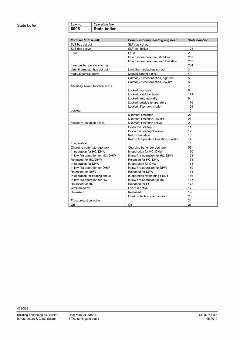
482/588
Building Technologies Division User Manual LMS14… CC1U7471en Infrastructure & Cities Sector 6 The settings in detail 11.05.2012
Line no. Operating line
8005 State boiler
Enduser (info level) Commissioning, heating engineer State number
SLT has cut out SLT has cut out 1
SLT test active SLT test active 123
Fault Fault 2
Flue gas temperature, shutdown 232 Flue gas temperature, load limitation 233 Flue gas temperature to high 234
Limit thermostat has cut out Limit thermostat has cut out 3
Manual control active Manual control active 4
Chimney sweep function, high-fire 5 Chimney sweep function, low-fire 6 Chimney sweep function active 7 Locked, manually 8 Locked, solid fuel boiler 172 Locked, automatically 9 Locked, outside temperature 176 Locked, Economy mode 198 Locked 10
Minimum limitation 20 Minimum limitation, low-fire 21 Minimum limitation active Minimum limitation active 22
Protective startup 11 Protective startup, low-fire 12 Return limitation 13 Return temperature limitation, low-fire 14 In operation 18
Charging buffer storage tank Charging buffer storage tank 59 In operation for HC, DHW In operation for HC, DHW 170 In low-fire operation for HC, DHW In low-fire operation for HC, DHW 171 Released for HC, DHW Released for HC, DHW 173 In operation for DHW In operation for DHW 168 In low-fire operation for DHW In low-fire operation for DHW 169 Released for DHW Released for DHW 174 In operation for heating circuit In operation for heating circuit 166 In low-fire operation for HC In low-fire operation for HC 167 Released for HC Released for HC 175 Overrun active Overrun active 17 Released Released 19 Frost protection plant active 23
Frost protection active 24
Off Off 25
State boiler

483/588
Building Technologies Division User Manual LMS14… CC1U7471en Infrastructure & Cities Sector 6 The settings in detail 11.05.2012
Line no. Operating line
8007 State solar
Enduser (info level) Commissioning, heating engineer State number
Manual control active Manual control active 4
Fault Fault 2
Frost protection collector active Frost protection collector active 52
Recooling active Recooling active 53
Max stor tank temp reached Max stor tank temp reached 54
Evaporation protection active Evaporation protection active 55
Overtemp protection active Overtemp protection active 56
Max charg temp reached Max charg temp reached 57
Charging DHW + buffer+swi pool Charging DHW + buffer + swi pool 151
Charging DHW + buffer Charging DHW + buffer 152
Charging DHW + swi pool Charging DHW + swi pool 153
Charging buffer + swimming pool Charging buffer + swimming pool 154
Charging DHW Charging DHW 58
Charging buffer storage tank Charging buffer storage tank 59
Charg swimm pool Charg swimm pool 60 Min charg temp not reached 61 Temp diff insufficient 62
Radiation insufficient Radiation insufficient 63
Line no. Operating line
8008 State solid fuel boiler
Enduser (info level) Commissioning, heating engineer State number
Manual control active Manual control active 4
Fault Fault 2
Overtemp protection active Overtemp protection active 56
Locked, manually 8 Locked, automatically 9 Locked 10 Minimum limitation 20 Minimum limitation, low-fire 21 Minimum limitation active Minimum limitation active 22
Protective startup 11 Protective startup, low-fire 12 Return temperature limitation 13 Return temp limitation, low-fire 14 In operation for heating circuit In operation for heating circuit 166 In low-fire operation for HC In low-fire operation for HC 167 In operation for DHW In operation for DHW 168 In low-fire operation for DHW In low-fire operation for DHW 169 In operation for HC, DHW In operation for HC, DHW 170 In low-fire operation for HC, DHW In low-fire operation for HC, DHW 171 Overrun active Overrun active 17 In operation In operation 18
Assisted firing fan active Assisted firing fan active 163
Released Released 19
Frost protection plant active 23 Frost protection boiler active 141 Frost protection active 24 Off Off 25
State solar
State solid fuel boiler
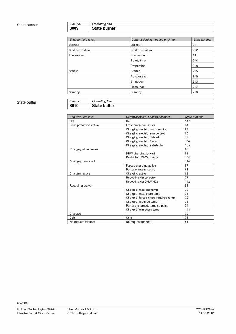
484/588
Building Technologies Division User Manual LMS14… CC1U7471en Infrastructure & Cities Sector 6 The settings in detail 11.05.2012
Line no. Operating line
8009 State burner
Enduser (info level) Commissioning, heating engineer State number
Lockout Lockout 211
Start prevention Start prevention 212
In operation In operation 18
Safety time 214
Prepurging 218
Startup Startup 215
Postpurging 219
Shutdown 213
Home run 217
Standby Standby 216
Line no. Operating line
8010 State buffer
Enduser (info level) Commissioning, heating engineer State number
Hot Hot 147
Frost protection active Frost protection active 24
Charging electric, em operation 64 Charging electric, source prot 65 Charging electric, defrost 131 Charging electric, forced 164 Charging electric, substitute 165 Charging el im heater 66 DHW charging locked 81 Restricted, DHW priority 104 Charging restricted 124
Forced charging active 67 Partial charging active 68 Charging active Charging active 69
Recooling via collector 77 Recooling via DHW/HCs 142 Recooling active 53 Charged, max stor temp 70 Charged, max charg temp 71 Charged, forced charg required temp 72 Charged, required temp 73 Partially charged, temp setpoint 74 Charged, min charg temp 143 Charged 75 Cold Cold 76
No request for heat No request for heat 51
State burner
State buffer

485/588
Building Technologies Division User Manual LMS14… CC1U7471en Infrastructure & Cities Sector 6 The settings in detail 11.05.2012
Line no. Operating line
8011 State swimming pool
Enduser (info level) Commissioning, heating engineer State number
Manual control active Manual control active 4
Fault Fault 2
Heating mode restricted Heating mode restricted 106
Forced heat release Forced heat release 110
Heating mode, generation 155 Heating mode 137 Heated, max. sw. pool temp Heated, max sw pool temp 156 Heated, solar setpoint 158 Heated, source setpoint 157 Heated 159 Heating mode, solar Off 160 Heating mode, heat source Off 161 Heating Off 162
Cold Cold 76
6.30 Diagnostics of cascaded system For diagnostics purposes, a number of setpoints, actual values, switching states of relays and heat source priorities can be displayed.
Line no. Operating line
8100...8199
State swimming pool

486/588
Building Technologies Division User Manual LMS14… CC1U7471en Infrastructure & Cities Sector 6 The settings in detail 11.05.2012
6.31 Diagnostics of heat sources For diagnostic purposes, the various setpoints, actual values, relay switching states and meter readings can be displayed.
Line no. Operating line
8300 .. 8699
6.31.1 Process values Using the QAA75…/AVS37… or the PC software ACS700/ACS790, process variables of the sequence of phases and speed control can be visualized. The following variables can be shown on menu Diagnostics of heat generation:
Line no. Operating line
8323 Fan speed Current fan speed.
Line no. Operating line
8324 Setpoint fan Fan speed currently required.
Line no. Operating line
8325 Current fan control Current fan control.
Line no. Operating line
8329 Ionization current Actual value of ionization current.
Line no. Operating line
8390 Current phase number Current phase of burner control sequence (see sequence diagram --- phase).
6.32 Diagnostics of consumers For diagnostic purposes, the various setpoints, actual values, relay switching states and meter readings can be displayed.
Line no. Operating line
8700 .. 9099
Fan speed
Set point fan
Current fan control
Ionization current
Current phase number
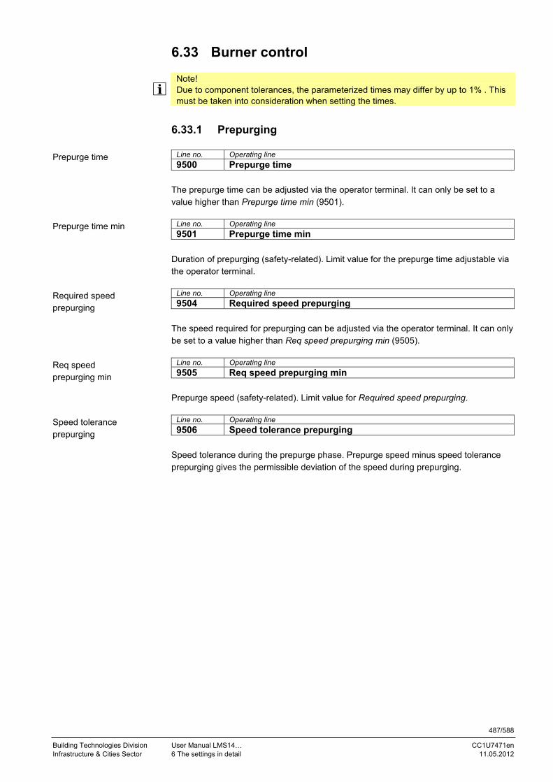
487/588
Building Technologies Division User Manual LMS14… CC1U7471en Infrastructure & Cities Sector 6 The settings in detail 11.05.2012
6.33 Burner control
Note! Due to component tolerances, the parameterized times may differ by up to 1% . This must be taken into consideration when setting the times.
6.33.1 Prepurging
Line no. Operating line
9500 Prepurge time The prepurge time can be adjusted via the operator terminal. It can only be set to a value higher than Prepurge time min (9501).
Line no. Operating line
9501 Prepurge time min Duration of prepurging (safety-related). Limit value for the prepurge time adjustable via the operator terminal.
Line no. Operating line
9504 Required speed prepurging The speed required for prepurging can be adjusted via the operator terminal. It can only be set to a value higher than Req speed prepurging min (9505).
Line no. Operating line
9505 Req speed prepurging min Prepurge speed (safety-related). Limit value for Required speed prepurging.
Line no. Operating line
9506 Speed tolerance prepurging Speed tolerance during the prepurge phase. Prepurge speed minus speed tolerance prepurging gives the permissible deviation of the speed during prepurging.
Prepurge time
Prepurge time min
Required speed prepurging
Req speed prepurging min
Speed tolerance prepurging

488/588
Building Technologies Division User Manual LMS14… CC1U7471en Infrastructure & Cities Sector 6 The settings in detail 11.05.2012
6.33.2 Ignition
Line no. Operating line
9512 Required speed ignition Required speed at the time of ignition, which can be adjusted via the operator terminal. It can not be set to a value higher than Required speed ignition max (9513).
Line no. Operating line
9513 Required speed ignition max Required speed ignition (safety-related). Limit value for the adjustable Required speed ignition.
Line no. Operating line
9514 Speed tolerance ignition Speed tolerance during the ignition phase. Required speed ignition plus/minus speed tolerance ignition gives the permissible deviation of the speed during the ignition phase.
Line no. Operating line
9517 Preignition time If the parameter is set to 0, phase TVZ lasts the minimum of 0.2 s.
Line no. Operating line
9518 Safety time Total safety time. The safety time can be subdivided into a phase with and a phase without ignition. Duration of safety time without ignition: Safety time minus safety time with ignition.
Note! The safety time (TSA) is set in increments of 200 ms. Due to the 1% tolerance of the parameterized times and the switching times of the controlling elements, the next lower value of the required maximum safety time must be parameterized. If the maximum safety time shall be <5 seconds, the safety time to be set for the LMS14... is 4.8 seconds.
Line no. Operating line
9519 Safety time with ignition Safety time with ignition On.
Required speed ignition
Required speed ignition max
Speed tolerance ignition
Preignition time
Safety time
Safety time with ignition

489/588
Building Technologies Division User Manual LMS14… CC1U7471en Infrastructure & Cities Sector 6 The settings in detail 11.05.2012
6.33.3 Operation
Line no. Operating line
9524 Required speed LF Speed required at low-fire, which can be adjusted via the operator terminal. It can only be set to a value above the Required speed LF min (9525).
Line no. Operating line
9525 Required speed LF min Speed required for low-fire minimum (safety-related). Limit value for Required speed LF (9524).
Line no. Operating line
9526 Speed tolerance LF Speed tolerance at low-fire. Required speed LF (9524) minus speed tolerance low-fire gives the permissible deviation of the speed during the operating phase.
Line no. Operating line
9529 Required speed HF Speed required at high-fire, which can be adjusted via the operator terminal. It can not be set to a value above the Required speed HF max (9530).
Line no. Operating line
9530 Required speed HF max Speed required for high-fire maximum (safety-related). Limit value for Required speed HF (9529).
Line no. Operating line
9531 Speed tolerance HF Speed tolerance at high-fire. Required speed HF (9529) plus speed tolerance high-fire gives the permissible deviation of the speed during the operating phase.
Line no. Operating line
9534 Optg time with ignition load Control with ignition load prior to change to the operating phase (interval for stabilization of flame).
Required speed LF
Required speed LF min
Speed tolerance LF
Required speed HF
Required speed HF max
Speed tolerance HF
Optg time with ignition load

490/588
Building Technologies Division User Manual LMS14… CC1U7471en Infrastructure & Cities Sector 6 The settings in detail 11.05.2012
6.33.4 Postpurging
Line no. Operating line
9540 Postpurge time Duration of postpurging, which can be adjusted via the operator terminal. It can only be set to a value above the Postpurge time min (9542).
Line no. Operating line
9541 Postpurge time TL max Duration of postpurge time after a temperature limiter/safety limit thermostat has responded (safety-related).
Line no. Operating line
9542 Postpurge time min Duration of postpurging (safety-related). Limit value for the postpurge time which can be adjusted via the operator terminal.
Line no. Operating line
9544 Postpurge time 2 Duration of postpurging that can be interrupted. To be activated via Home run mode (9613).
Line no. Operating line
9551 Required speed stop max Speed from which the current speed is set to 0 (safety-related). When changing to Standby, the current speed must be lower than this speed.
Line no. Operating line
9552 Required speed stop Fan speed required when stopped (safety-related).
Postpurge time
Postpurge time TL max
Postpurge time min
Postpurge time 2
Required speed stop max
Required speed stop

491/588
Building Technologies Division User Manual LMS14… CC1U7471en Infrastructure & Cities Sector 6 The settings in detail 11.05.2012
6.33.5 Configuration
Line no. Operating line
9610 Capacity Up to 70 kW Up to 120 kW Above 120 kW
In compliance with the standards, the LMS14... supports 2 capacity ranges: Up to 70 kW See up to 120 kW (the LMS14... does not differentiate). Up to 120 kW Capacity range up to 120 kW (see sequence diagram for burner capacities <120 kW). Above 120 kW Capacity range above 120 kW (see sequence diagram for burner capacities >120 kW.
Line no. Operating line
9611 LP configuration LP mode 1 LP mode 2 LP mode 3 LP mode 4 LP mode 5
Configuration of input for air pressure switch: LP mode 1 No monitoring by air pressure switch (input can be used for some other function). LP mode 2 Monitoring by air pressure switch from phase TV to phase TVZ. LP mode 3 Monitoring by air pressure switch in phase TV. LP mode 4 Monitoring by air pressure switch in phases TW1, TW2 and TVZ. LP mode 5 Monitoring by air pressure switch during Standby.
Warning! Here, the safety-related setting for input H7 is made. Function input H7 (6011) is of importance only if this parameter is set to LP mode 1. If, with this safety-related parameter, a function other than LP mode 1 is selected, Function input H7 (6011) only accepts None.
Capacity
LP configuration

492/588
Building Technologies Division User Manual LMS14… CC1U7471en Infrastructure & Cities Sector 6 The settings in detail 11.05.2012
Line no. Operating line
9612 GP configuration GP not connected GP connected
Configuration of input for gas pressure switch: GP not connected No monitoring by gas pressure switch (input can be used for some other function). GP connected Monitoring by gas pressure switch (see sequence diagram).
Warning! Here, the safety-related setting for input H6 is made. Parameter Function input H6 (6008) is of importance only when set to GP not connected. If, with this safety-related parameter, function GP connected is selected, parameter Function input H6 (6008) only accepts None.
Line no. Operating line
9613 Home run mode Startup with home run Startup without home run
Selection of Postpurging mode. Startup with home run At the end of postpurging TN2, the change to home run is always made. Startup without home run Direct startup from postpurging TN2 possible (interruptable postpurging).
Line no. Operating line
9614 Postpurging level Run Prepurge
Selection of postpurging level at the end of the operating phase. Run Postpurging based on last operational control. Prepurge Postpurging at prepurge speed.
GP configuration
Home run mode
Postpurging level

493/588
Building Technologies Division User Manual LMS14… CC1U7471en Infrastructure & Cities Sector 6 The settings in detail 11.05.2012
Line no. Operating line
9615 Forced prepurging on error Off On
After a reset following lockout, after power ON, or after 24 hours in Standby mode, forced prepurging takes place in the TV phase for 21 seconds or during the Prepurge time, if the Prepurge time exceeds 21 seconds. The deviations identified by Z in the sequence diagram cause the burner control to effect forced prepurging the next time it is started up. Off Function is deactivated. On Function is activated.
Line no. Operating line
9616 Max speed Maximum speed that may never be reached.
Line no. Operating line
9617 Hall sensor pulses/rev Configuration of Hall pulses per revolution of the fan: Hall mode 1: 1 pulse per revolution Hall mode 2: 2 pulses per revolution Hall mode 3: 3 pulses per revolution Hall mode 4: 4 pulses per revolution Hall mode 5: 5 pulses per revolution Hall mode 6: 6 pulses per revolution
Warning! When selecting a suitable fan, note the maximum input frequency of the fan Hall input at the LMS14... (refer to chapter Fan PWM/Hall connection facility). If the maximum input frequency is exceeded, fan speed measurements will be wrong.
Line no. Operating line
9618 Ion curr level extran light Ionization current level extraneous light. If the threshold is exceeded in phases TLO through TVZ, there will be a response from the sequence of phases (refer to Sequence diagrams).
Line no. Operating line
9619 Ion curr level flame exting Ionization current level Flame extinguished. If the ionization current drops below this level, there will be a response from the sequence of phases in phases Interval (TI) and Normal operation (MOD) due to error (refer to Sequence diagrams).
Forced prepurging on error
Max speed
Hall sensor pulses/rev
Ion curr level extran light
Ion curr level flame exting

494/588
Building Technologies Division User Manual LMS14… CC1U7471en Infrastructure & Cities Sector 6 The settings in detail 11.05.2012
6.33.6 Fan control
Line no. Operating line
9626 Fan output/speed slope Slope of linear equation for output-speed conversion.
Line no. Operating line
9627 Fan output/speed Y-section Y-section of axis of linear equation for output-speed conversion.
Line no. Operating line
9630 Speed Kp Proportional coefficient of fan control.
Line no. Operating line
9631 Speed Tn Integral action time of fan control.
Line no. Operating line
9632 Speed Tv Derivative action time of fan control.
Fan output/speed slope
Fan output/speed Y-section
Speed Kp
Speed Tn
Speed Tv

495/588
Building Technologies Division User Manual LMS14… CC1U7471en Infrastructure & Cities Sector 6 The settings in detail 11.05.2012
6.33.7 Chimney drying
Line no. Operating line
9650 Chimney drying Off Temporarily Permanently
When chimney drying is activated, the function is started after shutdown when changing to Standby. Chimney drying can be interrupted by any request for heat and can be restarted when the sequence of phases returns to Standby. Off Function is deactivated. Temporarily The duration of chimney drying is dependent on parameter Duration chimney drying (9652). Permanently Chimney drying is continuously performed in Standby mode.
Line no. Operating line
9651 Req speed chimney drying Predefined speed that shall be used for drying the chimney.
Line no. Operating line
9652 Duration chimney drying Duration of chimney drying if temporal limitation is required.
Chimney drying
Req speed chimney drying
Duration chimney drying

496/588
Building Technologies Division User Manual LMS14… CC1U7471en Infrastructure & Cities Sector 6 The settings in detail 11.05.2012
6.33.8 Setpoint filter for fan speed control
Line no. Operating line
[3694.1] Time const 1 falling [3695.1] Time const 2 falling [3696.1] Time const 3 falling
These are the filter time constants for the speed setpoint of fan control when modulating from a higher to a lower speed level. The time constants act depending on parameters Upper speed threshold [3698.1] and Lower speed threshold [3699.1] and – when modulating down – can be subdivided into 3 ranges.
Line no. Operating line
[5283.1] Pt1TmeConst4MaxMin_1 Filter time constant for the speed setpoint of fan control when modulating from a higher to a lower level. The time constant acts in all phases, with the exception of TI and MOD, depending on the parameters Diff SetpFiltTmeConst [5285.1] (= Yes). Parameter Diff SetpFiltTmeConst [5285.1] is deactivated when set to No.
Line no. Operating line
[5284.1] Pt1TmeConst1MinMax_1 Filter time constant for the speed setpoint of fan control when modulating from a lower to a higher level. The time constant acts in all phases, with the exception of TI and MOD, depending on the parameters Diff SetpFiltTmeConst [5285.1] (= Yes). Parameter Diff SetpFiltTmeConst [5285.1] is deactivated when set to No.
Line no. Operating line
[3697.1] Time const rising Filter time constant for the speed setpoint of fan control when modulating from a lower to a higher speed level.
Line no. Operating line
[5285.1] Diff SetpFiltTmeConst No
Yes Selection parameter, which can be used to load different setpoint filter time constants to the PT1 setpoint filter, depending on the sequence of phases. If Diff SetpFiltTmeConst [5285.1] is set to No) the parameters with Time const 1 falling [3694.1], Time const 2 falling [3695.1], Time const 3 falling [3696.1] and Time const rising [3697.1] are used in all phases. If Diff SetpFiltTmeConst [5285.1] is set to Yes, the parameters with Time const 1 falling [3694.1], Time const 2 falling [3695.1], Time const 3 falling [3696.1] and Time const rising [3697.1] are used in phases TI and MOD. In all other phases, Pt1TmeConst4MaxMin_1 [5283.1] and Pt1TmeConst1MinMax_1 [5284.1] are used.
Time const 1/2/3 falling
Pt1TmeConst4MaxMin_1
Pt1TmeConst1MinMax_1
Time const rising
Diff SetpFiltTmeConst

497/588
Building Technologies Division User Manual LMS14… CC1U7471en Infrastructure & Cities Sector 6 The settings in detail 11.05.2012
Line no. Operating line
[3698.1] Upper speed threshold Upper speed threshold value up to which Pt1 filter time constant Time const 1 falling [3694.1] acts when the speed setpoint changes from a higher to a lower level. If the speed drops below this threshold value, filter time constant Time const 2 falling [3695.1] starts acting.
Line no. Operating line
[3699.1] Lower speed threshold Lower speed threshold value up to which Pt1 filter time constant Time const 2 falling [3695.1] acts when the speed setpoint changes from a higher to a lower level. If the speed drops below this threshold value, filter time constant Time const rising [3697.1] starts acting.
Line no. Operating line
[3997.1] Fan PWM min Minimum PWM controller load value of fan control (minimum control range value).
Line no. Operating line
[3998.1] Fan PWM max Maximum PWM controller load value of fan control (maximum control range value).
Line no. Operating line
[4269.1] Ion limitn low limit Ionization current limit from which the minimum speed is set to the current speed.
Line no. Operating line
[4270.1] Ion limitn delta Hysteresis added to the Ion limitn low limit [4269.1]. From Ion limitn low limit [4269.1] + Ion limitn delta [4270.1], the lower speed limit is reduced every 0.2 seconds.
Line no. Operating line
[4398.1] IonFlGuard slope pos This value indicates the increase of the ionization current per second.
Line no. Operating line
[4397.1] IonFlGuard slope neg This value indicates the decrease of the ionization current per second.
Line no. Operating line
[4273.1] Ion limitn filt time Filter time constant for ionization current maintenance limit.
Upper speed threshold
Pt1 lower speed threshold
Fan PWM min
Fan PWM max
Ion limitn lower limit
Ion limitn delta
IonFlGuard slope pos
IonFlGuard slope neg
Ion limitn filt time

498/588
Building Technologies Division User Manual LMS14… CC1U7471en Infrastructure & Cities Sector 6 The settings in detail 11.05.2012
Line no. Operating line
[4337.1] Enable QAA fan para Off On
Under certain conditions, the fan parameters for ignition load, low-fire, high-fire, prepurging and postpurging can be set via the QAA75…/AVS37… Since these fan parameters are basically in the safety-related area and – as a general rule – safety-related values cannot be changed via the QAA75…/AVS37…, following applies:
The respective parameters are available in 2 groups (both safety-related and non-safety-related)
The change between the 2 parameter groups can be parameterized via the safety-related flag Enable QAA fan para [4337.1]
Off Fan parameters cannot be changed via the operator terminal. On Fan parameters can be changed via the operator terminal. Overview of safety-related and non-safety-related parameters:
Parameters QAA75…/
AVS37… Safety-related parameters
Required speed prepurging (9504) ≥ Req speed prepurging min (9505)
Required speed ignition (9512) ≤ Required speed ignition max (9513)
Required speed LF (9524) ≥ Required speed LF min (9525)
Required speed HF (9529) ≥ Required speed HF max 9530)
Prepurge time (9500) ≥ Prepurge time min (9501)
Postpurge time (9540) ≥ Postpurge time min (9542)
Key Line no. Meaning
9504 N_Vor_QAA Speed required for prepurging (QAA)
9505 N_Vor Minimum speed required for prepurging
9512 N_ZL_QAA Speed required for ignition
9513 N_ZL Maximum speed required for ignition
9524 N_TL_QAA Speed required for low-fire
9525 N_TL Minimum speed required for low-fire
9529 N_VL_QAA Speed required for high-fire
9530 N_VL Maximum speed required for high-fire
9500 Tv_QAA Prepurge time
9501 Tv Derivative action time
9540 Tn_QAA Postpurge time
9542 Tn Integral action time
Line no. Operating line
[4352.1] Fan PWM min prepurg Minimum fan PWM during prepurging for monitoring the fan speed.
Enable QAA fan para
Fan PWM min prepurg

499/588
Building Technologies Division User Manual LMS14… CC1U7471en Infrastructure & Cities Sector 6 The settings in detail 11.05.2012
Line no. Operating line
[4612.1] Fan PWM max prepurg Maximum fan PWM during prepurging for monitoring the fan speed.
Line no. Operating line
[4613.1] Fan PWM min ignition Minimum fan PWM at ignition for monitoring the fan speed.
Line no. Operating line
[4353.1] Fan PWM max ignition Maximum fan PWM at ignition for monitoring the fan speed.
Line no. Operating line
[4354.1] Fan PWM min low-fire Minimum fan PWM at low-fire for monitoring the fan speed.
Line no. Operating line
[4355.1] Fan PWM max high-fire Maximum fan PWM at high-fire for monitoring the fan speed.
Line no. Operating line
[4366.1] Max speed prepurging Maximum permissible fan speed during prepurging.
Line no. Operating line
[4378.1] Config reaction LT/SLT Start prevention
Lockout position Response if the mechanical limit thermostat (LT)/safety limit thermostat (SLT) cuts out. In the following, every start attempt made by the burner control is counted as such.
Fan PWM max prepurg
Fan PWM min ignition
Fan PWM max ignition
Fan PWM min low-fire
Fan PWM max high-fire
Max speed prepurging
Config reaction LT/SLT

500/588
Building Technologies Division User Manual LMS14… CC1U7471en Infrastructure & Cities Sector 6 The settings in detail 11.05.2012
Line no. Operating line
[3633.1] RepCounter flame TSA Maximum number of start attempts for establishment of flame. Maximum number of start attempts when – at the end of the safety time – no flame is detected. The set value indicates the total number of start attempts. Example: RepCounter flame TSA = 1 (maximum number of start attempts for establishment of flame = 1): The burner control initiates lockout after the first start attempt when – with a heat request pending – there is no establishment of flame at the end of the safety time (TSA). If a new start attempt shall be made (no repetitions), the value must be set to 2. RepCounter flame TSA = 4 (maximum number of start attempts for establishment of flame = 4): The burner control initiates lockout after the fourth start attempt when – with a heat request pending – there is no establishment of flame at the end of the safety time (TSA).
Note! This repetition counter is also an indication of the behavior of the system when the gas pressure switch responds during the safety time.
Line no. Operating line
[3632.1] RepCounter flame Maximum number of start attempts in the event of loss of flame during operation. Setting 25 means an infinite number of repetitions, and the counter has no impact. The set value indicates the total number of start attempts. Example: RepCounter flame = 1 (maximum number of start attempts upon loss of flame during
operation = 1): After the first loss of flame during operation, the burner control goes to lockout. If a new start attempt shall be made (no repetition), the value must be set to 2. RepCounter flame = 2 (maximum number of start attempts upon loss of flame during
operation = 2): After the second loss of flame during operation, the burner control goes to lockout.
RepCounter flame TSA
RepCounter flame

501/588
Building Technologies Division User Manual LMS14… CC1U7471en Infrastructure & Cities Sector 6 The settings in detail 11.05.2012
Line no. Operating line
[6086.1] Max StartAttempts Opt 1 Inactive Active
The function of the repetition counters Flame establishment and Loss of flame (RepCounter flame TSA [3633.1] and RepCounter flame [3632.1]) depends on Max StartAttemps Opt 1 [6086.1]. Inactive As described under RepCounter flame TSA [3633.1] and RepCounter flame [3632.1]. Active Repetition counter Loss of flame (RepCounter flame [3632.1]) remains inactive. When using this setting, errors Loss of flame during operation and No flame during safety time are handled by the repetition counter of RepCounter flame TSA [3633.1], which means that if one of these errors occurs, the number of remaining start attempts are reduced – starting from the maximum number RepCounter flame TSA [3633.1]. Examples of Max StartAttempts Opt 1 [6086.1] = Active RepCounter flame TSA [3633.1] = 1: Branching out to lockout position if, during the first start attempt, no flame was established when the safety time had elapsed, or in the event o floss of flame during operation. If another start attempt shall be allowed, RepZähler Flam TSA [3633.1] must be set to 2. RepCounter flame TSA [3633.1] = 2: Branching out to lockout position if, after the second start attempt, no flame was established before the safety time had elapsed or, when, after the first start attempt upon loss of flame during operation, no flame was established by the time the safety time had elapsed. RepCounter flame TSA [3633.1] = 3: Branching out to lockout position if, after the third start attempt, no flame was established before the safety time had elapsed or, when, after the second start attempt upon loss of flame during operation, no flame was established by the time the safety time had elapsed.
Line no. Operating line
[4495.1] Remote reset SLT Locking error caused by the safety limit thermostat (SLT), irrespective of electronic or mechanical safety limit thermostat.
Line no. Operating line
[4496.1] Remote reset air Locking error caused by the air pressure switch (LP error).
Max StartAttempts Opt 1
Remote reset SLT
Remote reset air

502/588
Building Technologies Division User Manual LMS14… CC1U7471en Infrastructure & Cities Sector 6 The settings in detail 11.05.2012
Line no. Operating line
[4497.1] Rem res extran light Locking error due to detection of extraneous light.
Line no. Operating line
[4498.1] Remote reset flame Locking error due to erroneous flame detection or loss of flame during operation.
Line no. Operating line
[4777.1] Prepu outp OEM limit Prepurge output predefined by OEM (OEM limit).
Line no. Operating line
[4778.1] Ign outp OEM limit Ignition load output predefined by OEM (OEM limit).
Line no. Operating line
[4779.1] LF outp OEM limit Low-fire output predefined by OEM (OEM limit).
Line no. Operating line
[4780.1] HF outp OEM limit High-fire output predefined by OEM (OEM limit).
Line no. Operating line
[4781.1] Max output OEM limit Maximum output predefined by OEM (OEM limit).
Line no. Operating line
[4782.1] Min output OEM limit Minimum output predefined by OEM (OEM limit).
Rem res extran light
Remote reset flame
Prepu outp OEM limit
Ign outp OEM limit
LF outp OEM limit
HF outp OEM limit
Max output OEM limit
Min output OEM limit

503/588
Building Technologies Division User Manual LMS14… CC1U7471en Infrastructure & Cities Sector 6 The settings in detail 11.05.2012
6.34 Program sequence of burner control
(function) 6.34.1 Program selection Certain sections of the burner control’s program can be changed via parameters, thereby providing a choice of control sequences. The burner control’s program sequences are distinguished mainly by their capacity ranges within which the boiler shall operate. In accordance with the standards, 2 capacity ranges are in use:
<120 kW ≥120 kW
For both capacity ranges, a number of parameter setting choices are available, enabling the OEM to match the burner control’s control sequence and time characteristics to individual needs. 6.34.2 Forced intermittent operation
Forced intermittent operation ensures that the burner control shuts down after a maximum of 24 hours of continuous operation. This is to make certain the burner control performs the required startup and shutdown sequences. 6.34.3 Burner control program
The burner control program ensures orderly operation of the unit including startup, shutdown, and flame supervision. The sequence itself can be changed by setting a number of parameters. If there are deviations from the required control sequence, or after a reset, the program will respond by triggering safety lockout (home run) followed by lockout, restart or start prevention, depending on the settings made. Sequence control is phase-oriented. The individual phases of the program are summarized to groups, such as startup, operation, shutdown and home run. After a reset (power ON), the burner control starts its home run. Depending on the available (parameterized) input/output signals or program times (e.g. prepurging), the individual phases of the program are executed or skipped. The burner control’s program is designed for intermittent operation. To confirm correct functioning (detection of faults); a complete operating cycle is required. In the Standby position, the burner control is ready to operate and waits for a request for heat from the controller, or it prevents burner startup (release missing). The burner control maintains the operation position until requests for heat from the controller are no longer present, but for no more than 24 hours. After this period of time, the burner control will automatically trigger forced intermittent operation.

504/588
Building Technologies Division User Manual LMS14… CC1U7471en Infrastructure & Cities Sector 6 The settings in detail 11.05.2012
6.34.4 Burner capacities
EN 676 (Nov 2003)
120 kW >120 kW
Air supply failure – fan speed
-- during pre purging
Air flow failure during prepurge shall at least proceed to safety shutdown.
Safety shutdown followed by a single attempt at restart is permitted.
If this restart attempt fails, then non-volatile lock-out shall occur.
Non-volatile lockout
Air supply failure – fan speed
– during ignition
Safety shutdown followed by a single attempt at restart is permitted.
If this restart attempt fails, then non-volatile lockout shall occur.
Non-volatile lockout
Air supply failure – fan speed
– in operation
Safety shutdown followed by a single attempt at restart is permitted.
If this restart attempt fails, then non-volatile lockout shall occur.
Non-volatile lockout
Air flow rate during prepurging
under the demanded value – air
pressure switch
Safety shutdown
or
the prepurge shall be continued until the required air rate is restored,
provided that the total controlled prepurge time is not reduced.
Fault during establishment of
flame
Maximum 3 restart attempts, whereby each restart calls for the complete start program.
After this action, the flame signal must be available at the end of the first safety time of the restart
attempt permitted last.
If not, the system must respond immediately by triggering safety shutdown, followed by non-volatile
lockout (reached by setting the repetition counter to 4).
For the restart, a value other than the forced prepurge time (T_ZWANG) can be set via the prepurge
time (T_VOR).
or
Immediately safety shutdown followed by non-volatile lock-out (reached by setting the repetition
counter to 1).
Loss of flame during operation Restart with full startup sequence.
After this action, the flame signal must be available after the permitted restart attempt when the
burner reaches its operating position.
If not, the system must respond immediately by triggering safety shutdown, followed by non-volatile
lockout (reached by setting the repetition counter to 4).
For the restart, a value other than the forced prepurge time (T_ZWANG) can be set via the prepurge
time (T_VOR)
or
Immediately safety shutdown followed by non-volatile lock-out (reached by setting the repetition
counter to 1).
Standard: DIN EN 483 (June 2000) <= 70 kW; EN 297; EN 298; DIN EN 656 (January 2000) >70 kW ...
< 300 kW; DIN EN 13836:2006(D) >300 kW ... 1000 kW; DIN EN 15417:2006 >70 kW ... <= 1000 kW;
DIN EN 15420 (DRAFT):2006 >70 kW ... <= 1000 kW

505/588
Building Technologies Division User Manual LMS14… CC1U7471en Infrastructure & Cities Sector 6 The settings in detail 11.05.2012
6.34.5 Sequence diagram for burner capacities ≤120 kW
7471d56e/0311 Figure 95: Sequence diagram for burner capacities ≤120 kW

506/588
Building Technologies Division User Manual LMS14… CC1U7471en Infrastructure & Cities Sector 6 The settings in detail 11.05.2012
6.34.6 Sequence diagram for burner capacities ≥120 kW
7471d55e/0311 Figure 96: Sequence diagram for burner capacities ≥120 kW

507/588
Building Technologies Division User Manual LMS14… CC1U7471en Infrastructure & Cities Sector 6 The settings in detail 11.05.2012
Key
Inputs ▲ If input is On, the change to the next phase on the right is made
▼ If input is Off, the change to the next phase on the right is made
XXX▲ If input is On, the change to phase XXX is made
XXX▼ If input is Off, the change to phase XXX is made
↑
If the input is On at the end of the phase, the change to the next phase on the right is
made
Input must be Off, otherwise home run
Input must be On, otherwise home run
Input must be Off, otherwise lockout
Input must be On, otherwise lockout
Input must be Off, otherwise shutdown
Input must be On, otherwise shutdown
Input must be Off, otherwise start prevention (phase STV)
Input must be On, otherwise start prevention (phase STV)
Outputs Output Off
Output On
Supervision of current fan speed
▲ If the speed is higher than the lower/upper limit, the change to the next phase on the right
is made
▼
If the speed is lower than lower/upper limit, the change to the next phase on the right is
made
Speed not permitted, home run if violation exceeds the tolerated time
Speed not permitted, lockout if violation exceeds the tolerated time
Lower/upper speed limit
Required speed
Response to errors In case of deviation: Forced prepurging (can be parameterized)
In case of deviation: Error counter No flame end of TSA is incremented. Lockout if counter
reads 4. Error counter is reset in operating phase
In case of deviation: Error counter GP errors during TSA is incremented. Start prevention
of 2 hours is triggered if counter reads 3. Error counter is reset in operating phase
In case of deviation: Error counter Air supply is incremented. Lockout if counter reads 2.
Error counter is reset after shutdown of controller
Subsequential phase * Next phase depending on parameterization

508/588
Building Technologies Division User Manual LMS14… CC1U7471en Infrastructure & Cities Sector 6 The settings in detail 11.05.2012
Line no. Meaning
9504 N_Vor_QAA Speed required for prepurging (QAA)
9505 N_Vor Minimum speed required for prepurging
9513 N_ZL Maximum speed required for ignition
9525 N_TL Minimum speed required for low-fire
9530 N_VL Maximum speed required for high-fire
9551 Maximum fan speed standstill
9552 Required speed standstill
9616 Maximum speed
9651 Speed required for chimney drying
BV Fuel valve
GP Gas pressure switch
KT Chimney drying
LP Air pressure switch
MOD Control mode
SAF With a certain error class, the unit jumps to this phase and all safety-
related outputs are deactivated.
STB Safety limit thermostat (SLT)
STOE If detecting a system error that shall drive the unit to a safe state (lockout),
the unit goes to the fault phase, which can only be quit by making a reset
STV Start prevention
STY Standby
TBRE Maximum time to reach ignition speed after prepurging
THL1 Maximum fan ramp-up time to prepurge speed
THL1A Maximum fan ramp-up time to ignition speed
THL2 Change to postpurging at last operating speed
THL2A Change to postpurging at prepurge speed
TI Interval
TLO Permitted time with air pressure switch closed or fan speed
TN2 Interruptable postpurging
TNA Postpurging at prepurge speed
TNB Permitted afterburn time
TN Postpurging at last operating speed
TNN Permitted time with fan speed
TVZ Preignition time
TW1 Maximum waiting time 1
TW2 Maximum waiting time 2
TSA1 1st safety time
TSA2 2nd safety time

509/588
Building Technologies Division User Manual LMS14… CC1U7471en Infrastructure & Cities Sector 6 The settings in detail 11.05.2012
Description of sequence diagrams
The burner control’s program is subdivided into several phases. A phase is characterized by a certain output and input configuration of the burner control. For the correct sequence and progression of signals, refer to the sequence diagrams. The progression of signals not shown in the sequence diagrams is summarized under Special cases. According to the sequence diagram, there is a permitted tolerance band with a corresponding limit for each level (e.g. Maximum speed required for ignition). The tolerance band is defined via parameter delta*. The limits are interrogated in the relevant sequence phases (refer to Sequence diagrams). Example: Ignition load Upper limit = N_ZL (9513) + delta
Lower limit = N_ZL (9513) delta In addition, the limit values are complemented by Required speed stop (9552) and Max speed (9616) (refer to Sequence diagrams). NoG_Max is the maximum speed which must never be reached. NoG_Null is the speed that must not be exceeded when changing to the Standby position.
Program times of sequence diagrams
Time Min.
(s)
Max.
(s)
Response
at the end
Designation
TNB 0.2 120 Lockout
position Afterburn time
TLO 0.2 51.0 Lockout
position
Open air pressure switch (fan overrun
time)
TNN 0.2 51.0 Lockout
position Up to speed = 0 (fan overrun time)
THL1 0.2 51.0 Lockout
position 1st fan ramp-up time
THL2 0.2 51.0 Lockout
position 2nd fan ramp-up time
Tv (t1) 0 51 Switching Prepurging
TBRE 0.2 51.0 Lockout
position Fan deceleration time to ignition load
TW1 0.2 51.0 Lockout
position
Waiting for internal sequence, fan speed
adjustment and combustion optimization
Tvz 0.2 20 Switching Preignition time
TSA 1.8 9.8 1) Safety time start
TSA1 0.2 9.6 2) 1) Safety time with ignition
TSA2 0.2 TSA-TSA1 2) 1) Safety time without ignition
Ti (t4) 0.2 10 Switching Interval operation with ignition load
TKT 0 Must be
defined no Chimney drying with N_KL
1) Lockout or repetition, depending on the flame signal and the parameters, plus a number of
parameter setting choices (refer to the relevant description) 2) In the case of parameterization with abortion of safety time on detection of flame, the times for TSA1
and TSA2 follow from the time the flame is established.
Note: TSA can never be exceeded

510/588
Building Technologies Division User Manual LMS14… CC1U7471en Infrastructure & Cities Sector 6 The settings in detail 11.05.2012
6.34.7 Repetition counter In the event of erroneous input signals, the repetition counters can be used to influence the sequence of phases.
Loss of flame during operation Per default, repetition counter Flame off during operation is set to infinite (25). If the fault occurs several times, the burner control does not initiate lockout.
No flame on completion of safety time If there is no flame on completion of the safety time, further repetitions are possible before lockout occurs.

511/588
Building Technologies Division User Manual LMS14… CC1U7471en Infrastructure & Cities Sector 6 The settings in detail 11.05.2012
6.34.8 Description of sequence diagrams
Standby PH_STANDBY (unlimited) Burner control waits for a request for heat from the controller. PH_STARTVER No external or internal release. The respective diagnostic code is delivered.
Startup The change from Standby to Operation is termed startup – triggered by a request for heat from the controller. If startup includes prepurging, startup begins with the THL1 phase, without prepurging with the THL1A phase. THL1 Maximum fan ramp-up time to prepurge level. With prepurge phase (t1) >0 or when there is a request for forced prepurging.
THL1A Maximum fan ramp-up time to ignition level. With prepurge phase (t1) = 0 and when there is no request for forced prepurging.
TV (t1) Prepurge phase.
TBRE Maximum time required to reach the ignition level after prepurging (reaching the speed band for ignition load).
TW1 Maximum waiting time until the following functions are completely performed: - Internal safety tests: These tests start with the beginning of the startup sequence and already run in the background during the preceding phases - Combustion optimization: Combustion optimum switched off, or stepper motor in the start position - Fan speed adjustment: Feedback when the required fan speed for the ignition load has been reached for the first time
TVZ Preignition time (can be parameterized, but minimum is 0.2 seconds). TSA1; TSA2 Ignition safety time. If no flame is established on completion of this period of time (including several reignition attempts), the burner control goes to lockout or makes a restart, depending on the parameter settings. If parameterized with abortion of safety time upon detection of flame, TSA can be shortened via flame establishment. TSA1 First part of safety time with ignition on. Fuel valve is open.
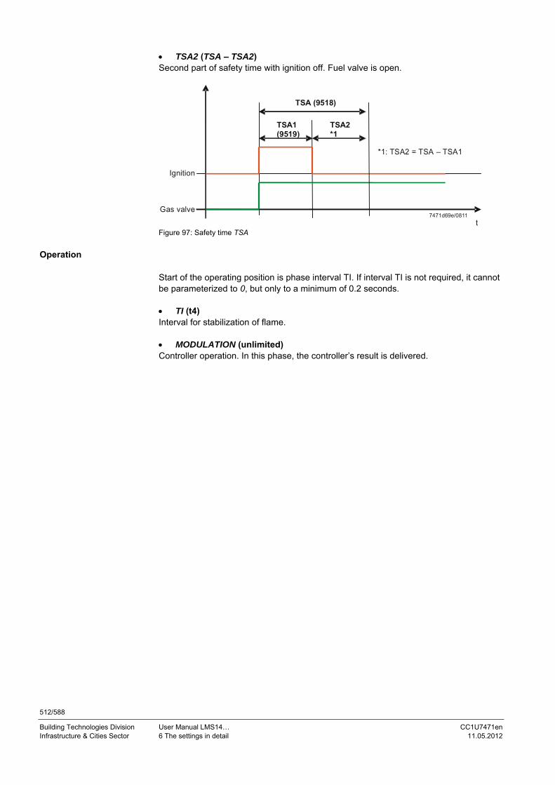
512/588
Building Technologies Division User Manual LMS14… CC1U7471en Infrastructure & Cities Sector 6 The settings in detail 11.05.2012
TSA2 (TSA – TSA2) Second part of safety time with ignition off. Fuel valve is open.
Gas valve
Ignition
TSA (9518)
TSA1 (9519)
TSA2 *1
*1: TSA2 = TSA – TSA1
t7471d69e/0811
Figure 97: Safety time TSA
Operation
Start of the operating position is phase interval TI. If interval TI is not required, it cannot be parameterized to 0, but only to a minimum of 0.2 seconds. TI (t4) Interval for stabilization of flame. MODULATION (unlimited) Controller operation. In this phase, the controller’s result is delivered.

513/588
Building Technologies Division User Manual LMS14… CC1U7471en Infrastructure & Cities Sector 6 The settings in detail 11.05.2012
Shutdown The change from the operating position to Standby is made when there is no more request for heat and is subdivided into Shutdown and Home run. Shutdown consists of postpurging, which can be switched off. With postpurging, there are 2 possible modes of operation, the difference being the way the fan is controlled. Parameter setting choice 1: THL2 (0.2 seconds) Change to postpurging with fan control used last in operation. TN1 (t8) Postpurging with fan control used last in operation. TN2 Interruptable postpurging with fan control used last in operation. If there is a new request for heat during this postpurge time, postpurging can immediately be interrupted. Parameter setting choice 2: THL2 Change to postpurging with fan control used during prepurging. THL2A Postpurging with fan control used during prepurging. TN2 Interruptable postpurging with fan control used last in operation. If there is a new request for heat during this postpurge time, postpurging can immediately be interrupted.
Home run The home run serves for making the change to the Standby position. It is made on a regular basis after shutdown. After extraordinary events (refer to Sequence diagram) or after a reset, it is used to bring the unit into the basic position (Standby). In the case of a new request for heat, fast startup is triggered during the home run. This is accomplished by reducing TNN followed by a direct change from phase TNN to phase THL1/THL1A. In that case, operating state Standby is skipped. TNB Permitted afterburn time. TLO Permitted time with air pressure switch closed (if present) or fan speed > 9525 - N_TL_Delta. TNN Permitted time with fan speed > NoG_Null.

514/588
Building Technologies Division User Manual LMS14… CC1U7471en Infrastructure & Cities Sector 6 The settings in detail 11.05.2012
Error
If the system detects a fault, it switches to the safety or lockout phase to run the burner control to a safe state. SAF When in a certain error class, a change to the SAP phase is made, and all safety-related outputs are deactivated. This way, lockout and a subsequent reset shall be avoided. If, for example, undervoltage is detected, which might lead to erroneous feedback signals, the system can go to this phase. When voltage returns to its normal level, this phase can be quit again with no need for making a reset. STOE If a system error is detected that shall run the burner control to a safe state (lockout), the unit goes to the lockout phase, which can only be quit again by making a reset.

515/588
Building Technologies Division User Manual LMS14… CC1U7471en Infrastructure & Cities Sector 6 The settings in detail 11.05.2012
Special cases (deviations) Forced prepurging Forced prepurging takes place via parameter Req speed prepurging min (9505) after … - an off time of more than 24 hours, - power ON, - shutdown due to an interruption of gas supply during the safety time. Forced prepurging takes place in phase TV. It lasts 21 seconds, or >21 seconds if the prepurge time is set to >21 seconds. The deviations marked Z in the sequence diagram cause the burner control to execute forced prepurging during the next start phase. Number of start attempts at the end of the ignition safety time (TSA) If no flame is established by the end of the safety time (TSA), the burner control … - can go to lockout, or - can trigger a repetition by changing to home run. Refer to section Maximum number of start attempts for establishment of flame. Loss of flame during operation If parameterized, in the event of loss of flame during operation, a change to home run with restart takes place (refer to section Maximum number of start attempts upon loss of flame during operation). Prepurging Prepurging can be deactivated by setting the prepurge time to 0 seconds. In that case – as shown in the sequence diagram – a change from phase THL1 to phase TW1 takes place. Preignition time If parameter Preignition time (9517) is set to 0 (no ignition prior to safety time (TSA)), phase TVZ is completed within the minimum time of 0.2 seconds. Forced intermittent operation After a maximum of 24 hours of uninterrupted operation, the unit is forced to shut down, ensuring regular shutdown to the standby phase. The timer for forced intermittent operation will be reset in the standby phase. Fast startup with forced intermittent operation is not possible. Ignition safety time (TSA) As described above, when evaluating the flame at the end of the ignition safety time, the behavior of the burner control can be influenced. Also, the second safety time (TSA2) should not be selected too short, thus making certain that there will be no erroneous evaluation of the flame due to simulation resulting from ignition. Postpurging Postpurging can be parameterized in 2 different ways. Either postpurging at the prepurge speed or at the speed used last in operation. The postpurge time is set via the prepurge time (Tn) (see above).

516/588
Building Technologies Division User Manual LMS14… CC1U7471en Infrastructure & Cities Sector 6 The settings in detail 11.05.2012
Startup from postpurging Direct startup from postpurging (TN2) can take place via Postpurging mode, provided the mode was selected without home run and no air pressure switch is used (LP mode 1 or LP mode 5). If there is a request for heat during postpurging (TN2), the home run is skipped and startup is immediately started without driving the fan to standstill during the home run.
Note! If monitoring of air supply is needed, interruptable postpurging is not permitted.
Start prevention Certain internal or external events can trigger start prevention. In that case, the burner control changes to phase STARTVER. The diagnostic code indicates the reason why burner startup was prevented. Some of the reasons are the following (among others): Short-circuit or interruption of sensor No gas pressure switch signal (depending on parameterization) Open air pressure switch input (depending on parameterization) Triggering of Limit thermostat function Some of the functions that lead to start prevention can be deactivated through parameterization.

517/588
Building Technologies Division User Manual LMS14… CC1U7471en Infrastructure & Cities Sector 6 The settings in detail 11.05.2012
6.34.9 Fan speed control Fan speed control is active during startup, shutdown, home run, and the operating phase. The purpose of fan speed control is to influence the fan motor in a way that the resulting fan speed (after settling) will lie within a permissible band of the current operating phase. Fan speed control allows the compensation of external influences, such as over- or undervoltage, shortest flue gas paths or longest flue gas paths, in defined ranges. Fan speed control can be adjusted via Speed Kp (9630), Speed Tn (9631) und Speed Tv (9632) (refer to chapter Fan control). The pulses from fan speed feedback can be parameterized using Hall sensor pulses/rev (9617). During adjustment of the fan speed by fan speed control, a transient response might occur. It is recommended to parameterize prepurging and ignition to the same level, thereby making use of prepurging for the settling process. If, for example, prepurging is parameterized > ignition, a second settling process will take place. This would extend the time required for startup. Fan speed control and speed parameters The fan control values are to be parameterized such that the values required and desired from the combustion point of view will be reached (flue way and rated voltage). Then, the associated fan speeds are to be defined based on the fan characteristics. In a first approach, the limit values for the permitted bands must be set to a high level (Speed tolerance prepurging (9506) and Speed tolerance ignition (9514) etc.). The values for fan speed control and fan speed can now be optimized. When the speed controller and the speeds in the individual phases are set, the speed bands are reduced to such a degree that in the event of unfavorable conditions, startup, operation and shutdown take place without triggering any fault status messages. Speed limits If readjustment of speed is desired, it should be made first. When optimization is completed, or the settings have been made, the speed limits are to be defined and set next. The limit values for the permissible bands should be set to a level where the fan speed lies inside the band, even if conditions are most unfavorable. If, by mistake, the fan speed is higher or lower, the worst-case consideration and the speed band are violated, leading to appropriate responses in the process (refer to Sequence diagrams). However, for a defined tolerance time, the sequence of phases tolerates certain deviations from the preset speed bands in the individual phases. This way, it is made certain that in the case of potential settling processes the speed controller will not immediately respond to violations of the speed bands, and that a response is triggered only if there is a lasting speed deviation in one if the phases.

518/588
Building Technologies Division User Manual LMS14… CC1U7471en Infrastructure & Cities Sector 6 The settings in detail 11.05.2012
6.34.10 Filter for fan speed setpoint (OEM) The fan speed setpoint can be filtered with a Pt1 algorithm. If there is a setpoint change from a lower to a higher value, the change can be slowed down with a Pt1 filter constant. If the setpoint changes from a higher to a lower value, there a 3 Pt1 filter constants to slow down the setpoint change and thus the current fan speed. The band of the 3 Pt1 filter constants from a higher to a lower value can be selected with 2 threshold parameters for the fan speed. These fan speed threshold parameters are only valid for a change from a higher to a lower value.
7471d65e/0311 Figure 98: Block circuit diagram Pt1 speed-setpoint filter Diff SetpFiltTmeConst [5285.1] make it possible to distinguish between different filter time constants depending on the phase. If Diff SetpFiltTmeConst [5285.1] is set to Yes, filter time constants Pt1TmeConst4MaxMin_1 [5283.1] and Pt1TmeConst1MinMax_1 [5284.1] apply in phases TI and MOD. In all other phases, the following filter time constants are used: Time const 1 falling [3694.1], Time const 2 falling [3695.1], Time const 3 falling [3696.1], Time const rising [3697.1], Upper speed threshold [3698.1], and Lower speed threshold [3699.1]. If Diff SetpFiltTmeConst [5285.1] is set to No, the following filter time constants are used in all phases: Time const 1 falling [3694.1], Time const 2 falling [3695.1], Time const 3 falling [3696.1], Time const rising [3697.1], Upper speed threshold [3698.1], and Lower speed threshold [3699.1]. In that case, Pt1TmeConst4MaxMin_1 [5283.1] and Pt1TmeConst1MinMax_1 [5284.1] have no impact.

519/588
Building Technologies Division User Manual LMS14… CC1U7471en Infrastructure & Cities Sector 6 The settings in detail 11.05.2012
The band of the 3 filter time constants Pt1 from a higher to a lower level can be selected with 2 threshold parameters for the fan speed. These fan speed threshold parameters are valid only when changing from a higher to a lower level. The setting is made via Upper speed threshold [3698.1] and Lower speed threshold [3699.1]. For modulating to a higher level, all phases have no speed thresholds that could be used to subdivide modulation into different ranges. The subdivision of ramp slope is only possible in the operating phases when modulating to a lower level. In that case, Diff SetpFiltTmeConst [5285.1] must be set to Yes. Modulating to a lower level upon shutdown when Diff SetpFiltTmeConst [5285.1] is set to Yes. In the event of shutdown at the end of postpurging and a fan speed setpoint of 0 rpm, the speed controller is switched off. This means that the fan’s PWM is switched off and the fan motor coasts – depending on the fan’s characteristic – until standstill is reached. In this range, there is no control by the speed controller. To enable the fan ramp to act when modulating to a lower level upon shutdown in phases TNB, TLO and TNN, the fan controller is switched off in home run only when the filtered fan speed setpoint drops below the speed threshold 2*NoGNull (Required speed stop max (9551)). Up to this threshold, the fan is controlled by the speed controller and modulates to a lower level, depending on the preselected setpoint. In that case, the setpoint filter must be set such that – under the most unfavorable conditions – the current fan speed reaches speed threshold 2*NoGNull within 51 seconds. If, within 51 seconds, the speed drops below the speed threshold, the burner control goes to non-volatile lockout (Albatros code 160 Fan speed error). If the burner control goes to lockout, the speed controller for the fan is still switched off. This means that when going to lockout, time constants (Pt1TmeConst4MaxMin_1 [5283.1] and Pt1TmeConst1MinMax_1 [5284.1]) have no impact.

520/588
Building Technologies Division User Manual LMS14… CC1U7471en Infrastructure & Cities Sector 6 The settings in detail 11.05.2012
Overview of filter coefficients (Diff SetpFiltTmeConst [5285.1] set to Yes)
7471d66e/0311 Figure 99: Setpoint filter in phases TI and MOD
BZ 9551
N_max
BZ 5283.1
Speed
Time
Speed controller switches off on shutdown
BZ 5284.1
Setpoint (unfiltered) Setpoint (filtered)
7471d67/0111
Figure 100: Setpoint filter in phases other than TI and MOD

521/588
Building Technologies Division User Manual LMS14… CC1U7471en Infrastructure & Cities Sector 6 The settings in detail 11.05.2012
Overview of filter coefficients (Diff SetpFiltTmeConst [5285.1] set to No)
7471d68en/0311
Figure 101: Setpoint filter in all phases
Key
Line no. Meaning
9530 N_Max Maximum fan speed required for high-fire
9525 N_Min Minimum fan speed required for low-fire
9551 Maximum fan speed stop
[3694.1] Pt1 time constant 1 on falling speed
[3695.1] Pt1 time constant 2 on falling speed
[3696.1] Pt1 time constant 3 on falling speed
[3697.1] Pt1 time constant on rising speed
[3698.1] Pt1 upper speed threshold falling
[3699.1] Pt1 lower speed threshold falling
[5283.1] Pt1 time constant 4 on falling speed
[5284.1] Pt1 time constant 1 on rising speed
[5285.1] Different ramps in all phases

522/588
Building Technologies Division User Manual LMS14… CC1U7471en Infrastructure & Cities Sector 6 The settings in detail 11.05.2012
6.35 PWM limitation The control range of the fan speed controller can be adjusted via Fan PWM min [3997.1] and Fan PWM max [3998.1] (refer to chapter Setpoint filter for fan speed control). 6.35.1 Supervising air supply by monitoring current fan speed Basically, acquisition of the fan speed is not failsafe. Without extra measures, monitoring the current fan speed is not sufficient to ensure air supply to the burner. Errors in the acquisition of the fan speed or fan can be compensated by an appropriate PWM level. Then, the acquired fan speed lies again within the valid range. To enable fan speed monitoring to detect such errors, the PWM range of fan speed control must be limited. For the relevant speed ranges used for prepurging, ignition and operation, suitable parameters for PWM limitation are available.
PWM limits Fan speed limits Min. Max. Min Max
Prepurging MinPwmPrepurge - 9505 – N_Vor_Delta
N_Vor_Max
Ignition - MaxPwmIgnition 9513 – N_ZL_Delta
9513 + N_ZL_Delta
Operation MinPwmLowLoad MaxPwmHighLoad 9525 – N_TL_Delta
9530 + N_VL_Delta
The PWM limits must be defined for the most unfavorable conditions. With the minimum limits, the ambient conditions must be selected such that the fan reaches the minimum speed with the given PWM. If the PWM value is still reached with the minimum speed, it is used as the minimum PWM value. The procedure is the same with the maximum limits, only in the reverse sense.
Note! Whether or not monitoring of the current fan speed is enough for supervision of the air supply must be clarified with the approval authorities and the fan manufacturer.

523/588
Building Technologies Division User Manual LMS14… CC1U7471en Infrastructure & Cities Sector 6 The settings in detail 11.05.2012
Limitation of PWM
The delivered manipulated variable can be limited via Fan PWM min [3997.1] and Fan PWM max [3998.1] (internal limitation of PWM). The setting range is from 0 to 100%. Depending on the phase, the fan speed controller receives from the phase sequence additional adjustable lower and upper limit values for PWM. Using these parameters, the output of the speed controller in phases Prepurging (Fan PWM min prepurg [4352.1] and Fan PWM max prepurg [4612.1]), Ignition (Fan PWM min ignition [4613.1] and Fan PWM max ignition [4353.1]) and Operation (Fan PWM min low-fire [4354.1] and Fan PWM max high-fire [4355.1]) can be limited in different ways. The Limitation function decides which of the PWM limitation values (internal PWM limits or external phase sequence PWM limit values) shall be used. It is always the greater value that is used with the minimum limits, and the smaller value with the maximum limits. If the PWM limits are set to >0% or <100%, there is a condition defining that for startup or the transition phases the control is active and limitation is inactive. This is to make certain that the control will not be erroneously limited during ramp up or phase transition, which would cause the unit to initiate lockout. The phases during which limitation is not allowed to be active are the following: THL1/THL1A (transition phase from Standby to Prepurging), TBRE (transition phase from Prepurging to Ignition) and THL2/THL2A (transition phase from Operation to Postpurging). During these phases, the controller must be given the possibility to correct control deviations, if necessary, to reach the monitored phases Prepurging, Ignition and Postpurging. In the event of error, the controller can correct the control deviation and the transition condition to the next phase is fulfilled, or the transition condition (speed threshold) is not reached and – after a tolerance time of 51 seconds – the phase sequence branches off to lockout. If, in the first case, the transition condition was fulfilled, PWM limitation would take effect in the next phase, possibly overriding the controller PWM (with the defined PWM limit value of the respective phase) and possibly leading to a speed violation by PWM limitation. When changing from a non-limited to a limited phase, limitation is suppressed for 4 software cycles, permitting further settling of the speed during the transition. In phases THL1/THL1A, TBRE and THL2/THL2A, the maximum PWM limits are also switched to inactive. When changing from a higher prepurge speed to a low ignition speed, the maximum ignition PWM limit might be approached from above, leading to a wrong response caused by the erroneous limitation.

524/588
Building Technologies Division User Manual LMS14… CC1U7471en Infrastructure & Cities Sector 6 The settings in detail 11.05.2012
PWM limits of speed control (control range)[3997.1] and[3998.1]
PWM limits in therespective phaseresulting from thesequence of phases
TNB TLO TNN THL1 TV TBRE TW1 TW2 TVZ TSA1 TSA2 TI MOD THL2 TN TN2
Phases during which PWM is not limited 10000
TN at N_VOR (9505)level
TN atMODlevel
T
nist
7471d50e/0111 Figure 102: Supervision of air supply by monitoring the current fan speed – limitation of PWM
Key
Line no. Meaning
[3997.1] Min. PWM Parameter fan minimum PWM output (minimum PWM)
[3998.1] Max. Pwm Parameter fan maximum PWM output (maximum PWM)
9505 N_VOR Minimum speed required for prepurging
TNB Permitted afterburn time
TLO Permitted time with air pressure switch closed or fan speed
TNN Permitted time with fan speed
THL1 Maximum fan ramp-up time to prepurge speed
TV Prepurge phase
TBRE Maximum time to reach ignition level after prepurging
TW1 Waiting phase 1
TW2 Waiting phase 2
TVZ Preignition time
TSA1 1st safety time
TSA2 2nd safety time
TI Interval
MOD Controller mode
THL2 Change to postpurging
TN Postpurging
TN2 Interruptable postpurging
nist Fan speed
t Time

525/588
Building Technologies Division User Manual LMS14… CC1U7471en Infrastructure & Cities Sector 6 The settings in detail 11.05.2012
6.36 Chimney drying Chimney drying (9650) offers 3 choices: 0: No chimney drying 1: Time-dependent chimney drying 2: Permanent chimney drying The fan speed for chimney drying can be set via Req speed chimney drying (9651). For time-dependent chimney drying, the time can be set via Duration chimney drying (9652). When the Chimney drying function is activated, it starts if the phase changes to Standby. In this case, the Chimney drying function is started. This function can be interrupted by a request for heat, to be restarted when the phase changes back to Standby.

526/588
Building Technologies Division User Manual LMS14… CC1U7471en Infrastructure & Cities Sector 6 The settings in detail 11.05.2012
6.37 Fan parameters settable as load values via QAA75…/AVS37…
Under certain conditions, the fan parameters for ignition load, low-fire, high-fire, pre- and postpurging can also be set via the QAA75…/AVS37... Since these fan parameters lie within the safety-related area and, basically, safety-related values cannot be changed via the QAA75…/AVS37…, following applies: The respective parameters are copied and the new parameters filed in the non-
safety-related area and must fulfill the following conditions:
Line no. QAA75… Safety-related parameters
Required speed prepurging (9504) ≥ Req speed prepurging min (9505)
Required speed ignition (9512) ≤ Required speed ignition max (9513)
Required speed LF (9524) ≥ Required speed LF min (9525)
Required speed HF (9529) ≥ ≤ Required speed HF max 9530)
Prepurge time (9500) ≥ Prepurge time min (9501)
Postpurge time (9540) ≥ Postpurge time min (9542)
Key Line no. Meaning
9504 N_Vor_QAA Speed required for prepurging (QAA)
9505 N_Vor Minimum speed required for prepurging
9512 N_ZL_QAA Speed required for ignition
9513 N_ZL Maximum speed required for ignition
9524 N_TL_QAA Speed required for low-fire
9525 N_TL Minimum speed required low-fire
9529 N_VL_QAA Speed required for high-fire
9530 N_VL Maximum speed required for high-fire
9500 Tv_QAA Prepurge time
9501 Tv Prepurge time minimum
9540 Tn_QAA Postpurge time
9542 Tn Postpurge time minimum
9551 Maximum fan speed stop
9552 Required speed stop
9616 Maximum speed
The change between the 2 parameter groups can be parameterized via a safety-
related flag Enable QAA fan para [4337.1] = Off (QAA setting parameters not enabled) = On (QAA setting parameters enabled)

527/588
Building Technologies Division User Manual LMS14… CC1U7471en Infrastructure & Cities Sector 6 The settings in detail 11.05.2012
Phases in
7471d51e/0111
Figure 103: Fan parameters settable as load values via QAA75…/AVS37… The values of the phase sequence to be set via the operator terminal are set as load values, either in the form of kW or as speeds in min-1. For the conversion of load values to speed values, a speed-output characteristic is parameterized. The speed limits defined by the OEM (safety-related values), which limit the values via the operator terminal and which can only be set via the ACS420, are maintained as speed values and cannot be entered as load values. If the values for the sequence of phases are preset as load values in kW, they will directly be converted to speeds via the predefined linear characteristic. The QAA fan speed parameters and QAA fan output parameters use the same line numbers in the operator terminal. This means that the decision on the setting (kW or min-1) must be made via the online DD which needs to be created. An online change between output and speed parameters is not possible. The output parameters are enabled via a factory setting at headquarters level. Also the speed tolerance limits of the LMS14... continue to be preset as speed values only. The LMS14... merely provides a process to approximately determine the speed from a predefined load. Whether the required (set) output is reached or whether it corresponds to the setting for all operating states is not checked and is the responsibility of the user. The linear equation for the load-speed conversion is to be defined by the OEM. Equivalent load values are available for the following speeds (non-safety-related):

528/588
Building Technologies Division User Manual LMS14… CC1U7471en Infrastructure & Cities Sector 6 The settings in detail 11.05.2012
Line no. Operating line
Menu: Boiler 2441 Fan speed heating max 2442 Fan speed full charging max 2443 Fan sp start value inst WH 2444 Fan speed DHW max 2452 Controller delay speed Menu: Burner control 9504 Required speed prepurging 9512 Required speed ignition 9524 Required speed LF 9529 Required speed HF 9626 Fan output/speed slope 9627 Fan output/speed Y-section Presetting speed values via the operator terminal Presetting of speed values for the different phases of sequence control: For that, as described in chapter Burner control, flag Enable QAA fan para [4337.1] must be set to On.
74
71
d42
e/0
111
Figure 104: Fan parameters settable as load values via QAA75…/AVS37… - presetting the speed value via the operator terminal
Additional parameters

529/588
Building Technologies Division User Manual LMS14… CC1U7471en Infrastructure & Cities Sector 6 The settings in detail 11.05.2012
Presetting load values via the operator terminal For the extension to enter load variables, the sequence of phases necessitates a conversion of load values to speed values. Internally, the sequence of phases continues to make the calculation based on speed values. The load values are made available via the operator terminal to be converted to speeds based on a linear equation predefined by the OEM. The linear equation is predefined via Fan output/speed slope (9626) and Fan output/speed Y-section (9627). It must be
defined by the OEM. For that, as described in chapter Burner control, flag Enable QAA fan para [4337.1] must be set to On.
74
71
d41
e/0
111
Figure 105: Fan parameters settable as load values via QAA75…/AVS37…- presetting load values via the operator terminal
Key
Line no. Meaning
9505 N_Vor Minimum speed required for prepurging
9513 N_ZL Maximum speed required for ignition
9525 N_TL Minimum speed required for low-fire
9530 N_VL Maximum speed required for high-fire
P_TL Output low-fire
P_VL Output high-fire
P_VL_Hz Output in heating mode
P_ZL Output ignition

530/588
Building Technologies Division User Manual LMS14… CC1U7471en Infrastructure & Cities Sector 6 The settings in detail 11.05.2012
The load parameters converted to speeds are filed in the non-safety-related area and must meet the following conditions:
Parameter Safety-related
parameter
Required speed prepurging (9504) ≥ Prepu outp OEM limit [4777.1]
Required speed ignition (9512) ≤ Ign outp OEM limit [4778.1]
Required speed LF (9524) ≥ LF outp OEM limit [4779.1]
Required speed HF (9529) ≤ HF outp OEM limit [4780.1]
Key Line no. Meaning
4777.1 P_Vor Output prepurging
4778.1 P_ZL Ignition load output
4779.1 P_TL Low-fire output
4780.1 P_VL Output high-fire
9504 N_Vor_QAA Speed required for prepurging
9512 N_ZL_QAA Speed required for ignition
9524 N_TL_QAA Speed required for low-fire
9529 N_VL_QAA Speed required for high-fire
The values of fan speed (Fan speed heating max (2441), Fan speed full charging max (2442), Fan sp start value inst WH (2443), Fan speed DHW max (2444) and Controller delay speed (2452)) are limited to Required speed LF (9524) and Required speed HF (9529). The linear equation y = m*x +b with m = Fan output/speed slope (9626) and b = Fan output/speed Y-section (9627) is used to calculate the required speed based on the preset output.

531/588
Building Technologies Division User Manual LMS14… CC1U7471en Infrastructure & Cities Sector 6 The settings in detail 11.05.2012
Example: For a load range of 2.1…22 kW and a speed range of 1,250…6,000 min-1 (rpm), the resulting slope is 239 and the y-axis section 742. This means that at a load of 12 kW, for instance, the speed is 3,610 min-1 (rpm).
y=m*x+b
12 P[kW]
3610
n[min-1]
7471d44/1209
Figure 106: Fan parameters settable as load values via QAA75…/AVS37…- load range
Key
Figure Meaning
3610 Speed value in 1/min
12 Output value in kW
y y coordinate
x x coordinate
m Slope of the line
b y-intercept of the line
P Leistung [kW]
n Drehzahl [1/min]
The load parameters must be limited by the OEM. For this purpose, menu Burner control includes parameters that serve as limits for the following load parameters: Fan speed heating max (2441) Fan speed full charging max (2442) Fan sp start value inst WH (2443) Fan speed DHW max (2444) Controller delay speed (2452) Req speed prepurging min (9505) Required speed ignition max (9513) Required speed LF min (9525), and Required speed HF max (9530) The following parameters included in the Burner control menu are to be determined and entered by the OEM:
Prepu outp OEM limit ([4777.1]) Ign outp OEM limit ([4778.1]) LF outp OEM limit ([4779.1]) HF outp OEM limit ([4780.1]) Max output OEM limit ([4781.1]) Min output OEM limit ([4782.1])

532/588
Building Technologies Division User Manual LMS14… CC1U7471en Infrastructure & Cities Sector 6 The settings in detail 11.05.2012
The input limits are determined from the equivalent OEM speed parameters and the inverse linear equation used for the conversion from load to speed. The values determined this way are entered in the respective parameters. The limits for Fan speed heating max (2441), Fan speed full charging max (2442), Fan speed DHW max (2444) and Controller delay speed (2452) are restricted to the range of Required speed LF (9524) and HF outp OEM limit [4780.1]. Fan sp start value inst WH (2443) from 0 to HF outp OEM limit [4780.1]. On the Burner control menu, the limits are defined as follows:
[4782.1]
9524
[4778.1]
9504
9512
[4777.1]
[4781.1]
[4779.1]
[4780.1]
9529
Safety-related value
Adjustable via operator terminal
0
2000
Numbers in brackets [ ] correspond to the line numbers7471d43e/0111
Figure 107: Fan parameters settable as load values via QAA75…/AVS37…- limits
Key Line no. Meaning
[4777.1] Prepurge output OEM limit
[4778.1] Ignition load output OEM limit
[4779.1] Low-fire output OEM limit
[4781.1] Maximum output OEM limit
[4780.1] High-fire output OEM limit
[4782.1] Minimum output OEM limit
9504 N_Vor_QAA Speed required for prepurging (QAA)
9512 Ignition output
9524 Low-fire output
9529 High-fire output
533/588
Building Technologies Division User Manual LMS14… CC1U7471en Infrastructure & Cities Sector 6 The settings in detail 11.05.2012
6.37.1 Limitation of ionization current Ion limitn low limit [4269.1] is used to determine the minimum speed in a way that ionization current errors cannot lead to shutdown. If Ion limitn low limit [4269.1] is set to 0, the function is deactivated. If the ionization current drops below the value of Ion limitn low limit [4269.1], the minimum speed is set to the current speed. If the ionization current is still too low, the lower speed limit will be increased every 0.2 seconds. The value of IonFlGuard slope pos [4398.1] indicates the increase per second. When the function is activated, this speed then determines the lower speed limit for a speed limitation, which will lead to higher modulation and a higher ionization current. If the ionization current exceeds the value of Ion limitn low limit [4269.1] plus the hysteresis Ion limitn delta [4270.1], (IonLimit + IonLimitDelta), the lower speed limit will be reduced every 0.2 seconds. The value of IonFlGuard slope neg [4397.1] indicates the drop per second. Line no. Operating line
Menu: Burner control [4269.1] Ion limitn low limit [4398.1] IonFlGuard slope pos [4270.1] Ion limitn delta [4397.1] IonFlGuard slope neg
6.37.2 Ionization current maintenance Function Ionization current maintenance is only available if limitation of the ionization current is activated. This function is to be activated by the heating expert by setting Fan speed ionization current (7050) to a level above Required speed LF min (9525). When the minimum fan speed limit exceeds this limit, a maintenance message is delivered. The maintenance limit for the fan speed lies between Required speed LF min (9525) and Required speed HF max (9530). The exact value must be defined by tests on a customer-specific basis. The purpose of maintenance Message ionization current (7051) is to detect a slow drift of the ionization current. Fan speed ionization current (7050) is used for that purpose. This parameter is greater than Required speed LF min (9525) and also greater than Fan speed ionization current (7050), which occurs in normal operation. If, due to ionization current drift, the value of Nmin rises above the value of Fan speed ionization current (7050) (due to function → Ionization current limitation), a maintenance message is delivered. Since a maintenance message shall not be delivered the very first moment the value is exceeded or, if exceeded, only once, 2 filters are used: The filter acquires the period of time during which the value has been exceeded The acquired period of time is reduced if both the current and the minimum fan
speed fall again below Fan speed ionization current (7050) If this time exceeds 10 minutes, a maintenance message is output
Additional parameters

534/588
Building Technologies Division User Manual LMS14… CC1U7471en Infrastructure & Cities Sector 6 The settings in detail 11.05.2012
6.38 Modulating pump
6.38.1 Modulation of heating circuit pump The speed of the heating circuit pump can be calculated based on the operating level or the heating curve. The selection is made via parameters Pump speed reduction (880/1180/1480) for heating circuits 1 to 3.
Operating level When using option Operating level, the speed of the heating circuit pump is calculated based on the current operating level. In the case of operating level Reduced, the pump is controlled to the parameterized minimum. In the case of operating level Comfort and activated floor curing function, the pump is controlled to the parameterized maximum.
Heating curve When using option Heating curve, the speed of the heating circuit pump is calculated based on the selected compensation variant (weather- or room-compensated).
Weather-compensated With compensation variant Weather-compensated (with or without room influence), the speed of the heating circuit pump is maintained at the parameterized minimum as long as the heating demand can be satisfied. To be able to also meet the heat demand with reduced speed, the flow temperature must be increased. The flow temperature increase can be parameterized. Parameter Curve readj at 50% speed (888) defines the flow temperature increase in percent when the pump speed is reduced by 50%. The speed of the heating circuit pump is calculated based on the flow temperature currently obtained and the current flow temperature setpoint. The actual value of the common flow temperature is used as the actual value. If no common flow sensor is installed, the actual value of the boiler flow is used. It is attenuated with a filter, the time constant can be parameterized (Filter time const speed ctrl (889)). (Example heating circuit 1) Line no. Operating line
880 Pump speed reduction 881 Starting speed 882 Pump speed min 883 Pump speed max 885 Pump speed min OEM 886 Pump speed max OEM 888 Curve readj at 50% speed 889 Filter time const speed ctrl 890 Flow setp readj speed ctrl [4291.1] Delay speed ctrl HC1 Line no. Operating line
8308 Boiler pump speed 8310 Boiler temp 8735 Speed heating circuit pump 1 8765 Speed heating circuit pump 2 8795 Speed heating circuit pump 3
Additional parameters
Info/diagnostics

535/588
Building Technologies Division User Manual LMS14… CC1U7471en Infrastructure & Cities Sector 6 The settings in detail 11.05.2012
Room-compensated
The speed of the heating circuit pump is calculated based on the heat request from the room controller. The greater the demand for heat, the higher the pump speed. The lowest pump speed is limited by the parameterized minimum, the highest by the parameterized maximum. If the heat request drops below the parameterized heating limit for the room controller (Heating limit room controller (761)), the pump will be deactivated on completion of the parameterized overrun time. (Example heating circuit 1) Line no. Operating line
761 Heating limit room controller 882 Pump speed min 883 Pump speed max 885 Pump speed min OEM 886 Pump speed max OEM
Additional parameters

536/588
Building Technologies Division User Manual LMS14… CC1U7471en Infrastructure & Cities Sector 6 The settings in detail 11.05.2012
6.38.2 Behavior when burner cycles During burner off times, the system will reach a point where – after a certain period of time – the supply of heat is no longer sufficient (current flow temperature lower than the flow temperature setpoint). Speed control would respond to this situation by increasing the pump’s speed, but this would lead to shorter burner off times. Also, noise problems would have to be expected due to higher pump modulation. For this reason, modulation of the heating circuit pump was matched to cycling burner operation. When the burner is shut down, pump modulation is maintained at the parameterized minimum speed. When the burner is switched on, the speed of the heating circuit pump is kept constant for an adjustable delay time. Modulation of the heating circuit pump is again calculated and delivered only when the delay time has elapsed, based on the current common flow temperature (boiler flow temperature). This means that the speed is increased only when the filtered common flow temperature is lower than the flow temperature setpoint. Higher pump speeds lead to longer burner running times. Filtering of the common flow temperature then prevents quick speed reductions if the boiler temperature already lies above the setpoint, but the burner’s switch-off point is not yet reached. When the burner is switched off, the pump’s speed is reduced again to the parameterized minimum. (Example of heating circuit 1) Line no. Operating line
880 Pump speed reduction 882 Pump speed min 883 Pump speed max 888 Curve readj at 50% speed 889 Filter time const speed ctrl 890 Flow setp readj speed ctrl [4291.1] Delay speed ctrl HC1 Line no. Operating line
8310 Boiler temp 8735 Speed heating circuit pump 1 8765 Speed heating circuit pump 2 8795 Speed heating circuit pump 3
Additional parameters
Info/diagnostics

537/588
Building Technologies Division User Manual LMS14… CC1U7471en Infrastructure & Cities Sector 6 The settings in detail 11.05.2012
6.38.3 Limitation of boiler temperature differential
Fundamentals When using a modulating heating circuit pump, the boiler temperature increase (that is, the temperature difference of boiler return and boiler flow) is limited. As a result, the current boiler flow temperature might not reach the flow temperature setpoint demanded by the heating circuit.
Purpose of limiting the boiler’s temperature differential Pump modulation in the heating circuit module calculates an increase of the flow temperature setpoint, thus ensuring that the heating circuit’s demand for heat can also be satisfied when the pump’s speed is reduced. An increase of the flow temperature setpoint also leads to a higher boiler temperature setpoint. When, for the time being, the return temperature remains at a constant level, an increase of the boiler temperature setpoint always also results in a higher boiler temperature increase or differential. To prevent thermal stress problems on the boiler due to a great boiler temperature differential, the latter is limited when operating a modulating heating circuit pump. Limitation of the boiler temperature differential is accomplished by limiting the boiler temperature setpoint. For that, the boiler temperature setpoint is limited depending on the acquired boiler return temperature. The extent of boiler temperature setpoint limitation is selected such that the boiler temperature differential reached will not be greater than the parameterized maximum (Temp differential max). As far as permitted by the heat demand from the heating circuit, the LMS14… strives to keep the boiler temperature differential at the level of the parameterized nominal differential (Temp differential nominal). Line no. Operating line
883 Pump speed max 1183 Pump speed max 1483 Pump speed max 2316 Temp differential max 2317 Temp differential nominal Line no. Operating line
8310 Boiler temp 8311 Boiler setpoint 8314 Boiler return temp
Additional parameters
Info/diagnostics

538/588
Building Technologies Division User Manual LMS14… CC1U7471en Infrastructure & Cities Sector 6 The settings in detail 11.05.2012
6.38.4 Conditions for limiting the boiler’s temperature differential Limitation of the boiler’s temperature differential is possible only if a valid value of the boiler return temperature is available. Another prerequisite is a valid value of Temp differential max (2316), which means that it must not be an OSV. Limitation of the boiler’s temperature differential is only effective in connection with pure space heating. As soon as a DHW request becomes active, limitation of the boiler’s temperature differential is suppressed. In Heating mode, the limitation is effective only if a request from the heating circuit with modulating pump is active. Limitation of the boiler’s temperature differential also remains effective when additional requests from other heating circuits are pending. In the case of systems with modulating boiler pump, limitation of the boiler’s temperature differential depends on the assignment of the boiler pump (Ctrl boiler pump/DHW valve) (5774). If the boiler pump is assigned to heating circuit 1 only, limitation becomes active when there is a request for heat from heating circuit 1. If the boiler pump is assigned to all heating circuits, limitation becomes active as soon as any of the heating circuits calls for heat. Line no. Operating line 2316 Temp differential max 5774 Ctrl boiler pump/DHW valve 6085 Function output P1
6.38.5 Limitation dependent on pump modulation Limitation of the boiler’s temperature differential is dependent on the current modulation of the heating circuit pump. Depending on the current degree of modulation, different preselected values are used for limiting the boiler’s temperature differential. As long as the modulating heating circuit pump is not controlled to the maximum speed, the parameterized nominal boiler temperature differential is used for limiting the boiler temperature increase. If there is a deficit in the supply of heat to the heating circuit, this can be compensated for via speed control by increasing pump modulation. The parameterized maximum value Temp differential max for the boiler’s temperature differential applies only when the modulating heating circuit pump is controlled with maximum PWM (maximum pump speed heating circuit x. Line no. Operating line
2316 Temp differential max Line no. Operating line
8314 Boiler return temp
Additional parameters
Additional parameters
Info/diagnostics

539/588
Building Technologies Division User Manual LMS14… CC1U7471en Infrastructure & Cities Sector 6 The settings in detail 11.05.2012
6.38.6 Limitation to the maximum differential If the modulating heating circuit pump is controlled to maximum speed, speed control is no longer capable of increasing the volumetric flow. In general, the heating circuit pump should be controlled at reduced speeds. For this reason, when the maximum speed is reached, adherence to the nominal boiler temperature differential is abandoned and only the parameterized maximum value Temp differential max (2316) is used for limiting the boiler’s temperature differential. But limitation of the boiler’s temperature differential to the maximum is not raised abruptly, but rather slowly in a linear manner from the last valid limitation level to the maximum. Raising of the boiler’s temperature differential to the maximum follows a ramp. The slope of the ramp depends on the time constant used for speed control (Filter time const speed ctrl (889/1189/1489)) and the difference between the nominal and the maximum value of the boiler temperature increase. The ramp is defined such that the transition from the nominal to the maximum differential is made with factor 5 of the relevant time constant. If, for instance, a time constant of 3 minutes is parameterized for speed control, a nominal value of 20 K and a maximum value of 35 K for the boiler’s temperature increase, the boiler temperature differential is raised by exactly 1 K per minute until the maximum value is reached. Line no. Operating line
889 Filter time const speed ctrl 1189 Filter time const speed ctrl 1489 Filter time const speed ctrl 2316 Temp differential max 2317 Temp differential nominal Line no. Operating line
8310 Boiler temp 8311 Boiler setpoint
Additional parameters
Info/diagnostics

540/588
Building Technologies Division User Manual LMS14… CC1U7471en Infrastructure & Cities Sector 6 The settings in detail 11.05.2012
6.38.7 Limitation to the nominal differential As long as the modulating heating circuit pump is not controlled to maximum speed, the parameterized nominal value Temp differential nominal (2317) applies. Limitation of the boiler’s temperature differential to the nominal value is not raised abruptly, but rather slowly in a linear manner from the last valid limitation level to the nominal value. The reduction of the boiler’s temperature differential to the nominal value follows a ramp. The slope of the ramp depends on the time constant used for speed control (Filter time const speed ctrl x (889/1189/1489)) and the difference between the maximum and the nominal value of the boiler’s temperature differential. The ramp is defined such that the transition from the maximum to the nominal value is made with factor 5 of the relevant time constant. If, for instance, a time constant of 3 minutes is parameterized for speed control, a nominal value of 20 K and a maximum of 35 K for the boiler’s temperature differential, the latter is raised by exactly 1 K per minute until the nominal differential is reached. If, due the boiler’s temperature differential, the flow temperature remains below the flow temperature setpoint called for by the heating circuit, speed control can increase the volumetric flow by increasing pump modulation, thereby supplying more heat to the heating circuit.
Line no. Operating line
889 Filter time const speed ctrl 1189 Filter time const speed ctrl 1489 Filter time const speed ctrl 2316 Temp differential max 2317 Temp differential nominal Line no. Operating line
8310 Boiler temp 8311 Boiler setpoint
6.39 List of displays Pending errors are assigned priorities. From priority 6, alarm messages are delivered, which are used by remote supervision (OCI). In addition, the alarm relay is set.
Additional parameters
Info/diagnostics

541/588
Building Technologies Division User Manual LMS14… CC1U7471en Infrastructure & Cities Sector 6 The settings in detail 11.05.2012
6.39.1 Error code list The LMS14... supports a 16-bit error code. Older types of operator units might display 8-bit error codes. If different from the 16-bit error code, the corresponding 8-bit error code is indicated in parentheses.
Error code
LPB code
Description of error Priority
10 Outside temperature, sensor error 6
20 Boiler temperature 1, sensor error 6
20 Boiler temperature 1, sensor error 9
25 Boiler temperature, solid fuel, sensor error 6
26 Common flow temperature, sensor error 6
28 Flue gas temperature, sensor error 6
28 Flue gas temperature, sensor error 9
30 Flow temperature 1, sensor error 6
31 Flow temperature 1, cooling, sensor error 6
32 Flow temperature 2, sensor error 6
38 Flow temperature, primary controller, sensor error 6
40 Return temperature 1, sensor error 6
40 Return temperature 1, sensor error 9
46 Cascade return temperature, sensor error 6
47 Common return temperature, sensor error 6
50 DHW temperature 1 sensor error 6
52 DHW temperature 2 sensor error 6
54 Flow temperature DHW, sensor error 6
57 DHW, circulation sensor error 6
60 Room temperature 1, sensor error 6
65 Room temperature 2, sensor error 6
68 Room temperature 3, sensor error 6
70 Storage tank temperature 1 (top), sensor error 6
71 Storage tank temperature 2 (bottom), sensor error 6
72 Storage tank temperature 3 (center), sensor error 6
73 Collector temperature 1, sensor error 6
78 Water pressure, sensor error 6
78 Water pressure, sensor error 9
82 LPB address collision 3
83 BSB wire cross-sectional/no communication 8
84 BSB wire address collision 3
85 BSB RF communication error 8
91 Data overrun in EEPROM 3
91 Data overrun in EEPROM 6
91 Data overrun in EEPROM 9
98 Extension module 1, error 8
99 Extension module 2, error 8
100 2 clock time masters 3
102 Clock time master without backup 3
103 Communication error 8
105 Maintenance message 5
109 Supervision boiler temperature 6
109 Supervision boiler temperature 9
110 STB (SLT) lockout 6
110 STB (SLT) lockout 9
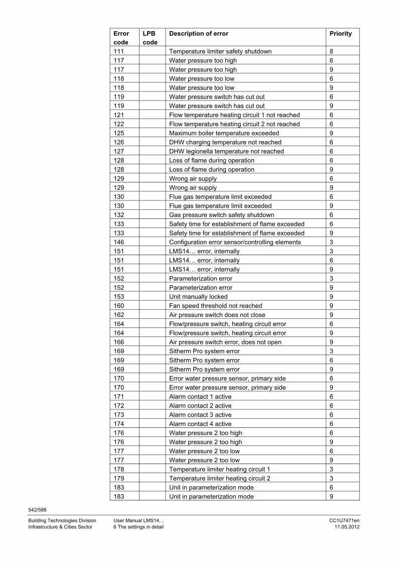
542/588
Building Technologies Division User Manual LMS14… CC1U7471en Infrastructure & Cities Sector 6 The settings in detail 11.05.2012
Error code
LPB code
Description of error Priority
111 Temperature limiter safety shutdown 8
117 Water pressure too high 6
117 Water pressure too high 9
118 Water pressure too low 6
118 Water pressure too low 9
119 Water pressure switch has cut out 6
119 Water pressure switch has cut out 9
121 Flow temperature heating circuit 1 not reached 6
122 Flow temperature heating circuit 2 not reached 6
125 Maximum boiler temperature exceeded 9
126 DHW charging temperature not reached 6
127 DHW legionella temperature not reached 6
128 Loss of flame during operation 6
128 Loss of flame during operation 9
129 Wrong air supply 6
129 Wrong air supply 9
130 Flue gas temperature limit exceeded 6
130 Flue gas temperature limit exceeded 9
132 Gas pressure switch safety shutdown 6
133 Safety time for establishment of flame exceeded 6
133 Safety time for establishment of flame exceeded 9
146 Configuration error sensor/controlling elements 3
151 LMS14… error, internally 3
151 LMS14… error, internally 6
151 LMS14… error, internally 9
152 Parameterization error 3
152 Parameterization error 9
153 Unit manually locked 9
160 Fan speed threshold not reached 9
162 Air pressure switch does not close 9
164 Flow/pressure switch, heating circuit error 6
164 Flow/pressure switch, heating circuit error 9
166 Air pressure switch error, does not open 9
169 Sitherm Pro system error 3
169 Sitherm Pro system error 6
169 Sitherm Pro system error 9
170 Error water pressure sensor, primary side 6
170 Error water pressure sensor, primary side 9
171 Alarm contact 1 active 6
172 Alarm contact 2 active 6
173 Alarm contact 3 active 6
174 Alarm contact 4 active 6
176 Water pressure 2 too high 6
176 Water pressure 2 too high 9
177 Water pressure 2 too low 6
177 Water pressure 2 too low 9
178 Temperature limiter heating circuit 1 3
179 Temperature limiter heating circuit 2 3
183 Unit in parameterization mode 6
183 Unit in parameterization mode 9

543/588
Building Technologies Division User Manual LMS14… CC1U7471en Infrastructure & Cities Sector 6 The settings in detail 11.05.2012
Error code
LPB code
Description of error Priority
195 Maximum duration of the refill per charging exceeded 6
195 Maximum duration of the refill per charging exceeded 9
196 Maximum duration of the refill per week exceeded 6
196 Maximum duration of the refill per week exceeded 9
209 Fault heating circuit 3
209 Fault heating circuit 6
214 Monitoring of motor 6
215 Fault fan air diverting valve 9
216 Fault boiler 6
216 Fault boiler 9
217 Sensor error 3
217 Sensor error 6
217 Sensor error 9
218 Pressure supervision 6
218 Pressure supervision 9
241 Flow sensor for yield measurement, error 6
242 Return sensor for yield measurement, error 6
243 Swimming pool sensor, error 6
260 217 Flow temperature 3, sensor error 3
270 215 Temperature difference, heat exchanger too large 9
317 214 Mains frequency outside permissible range 6
320 217 DHW charging temperature, sensor error 6
321 217 DHW outlet temperature, sensor error 6
322 218 Water pressure 3 too high 6
322 218 Water pressure 3 too high 9
323 218 Water pressure 3 too low 6
323 218 Water pressure 3 too low 9
324 146 Input BX, same sensors 3
325 146 Input BX/extension module, same sensors 3
326 146 Input BX/mixing group, same sensors 3
327 146 Extension module, same function 3
328 146 Mixing group, same function 3
329 146 Extension module/mixing group, same function 3
330 146 Sensor input BX1 without function 3
331 146 Sensor input BX2 without function 3
332 146 Sensor input BX3 without function 3
333 146 Sensor input BX4 without function 3
335 146 Sensor input BX21 without function 3
336 146 Sensor input BX22 without function 3
339 146 Collector pump Q5 missing 3
340 146 Collector pump Q16 missing 3
341 146 Sensor B6 missing 3
342 146 Solar charging sensor B31 missing 3
343 146 Solar integration missing 3
344 146 Solar controlling element buffer K8 missing 3
345 146 Solar controlling element swimming pool K18 missing 3
346 146 Solid fuel boiler pump Q10 missing 3
347 146 Solid fuel boiler comparative sensor missing 3
348 146 Solid fuel boiler address error 3
349 146 Buffer storage tank return valve Y15 missing 3
350 146 Buffer storage tank address error 3

544/588
Building Technologies Division User Manual LMS14… CC1U7471en Infrastructure & Cities Sector 6 The settings in detail 11.05.2012
Error code
LPB code
Description of error Priority
351 146 Primary controller/system pump, address error 3
352 146 Pressureless header, address error 3
353 146 Sensor B10 missing 3
371 209 Flow temperature heating circuit 3 6
372 209 Temperature limiter heating circuit 3 3
373 103 Extension module 3 8
374 169 Sitherm Pro calculation 6
374 169 Sitherm Pro calculation 9
375 169 BV stepper motor 9
376 169 Drift test limit value 3
376 169 Drift test limit value 6
376 169 Drift test limit value 9
377 169 Drift test prevented 9
378 151 Internal repetition 9
382 129 Repetition speed 9
384 151 Extraneous light 6
384 151 Extraneous light 9
385 151 Mains undervoltage 9
386 129 Fan speed tolerance 6
386 129 Fan speed tolerance 9
387 129 Air pressure tolerance 6
387 129 Air pressure tolerance 9
388 146 DHW sensor no function 3
426 151 Feedback flue gas damper 9
427 152 Configuration flue gas damper 3
429 218 Dynamic water pressure too high 6
429 218 Dynamic water pressure too high 9
430 218 Dynamic water pressure too low 6
430 218 Dynamic water pressure too low 9
431 217 Sensor primary heat exchanger 6
431 217 Sensor primary heat exchanger 9
432 151 Function earth not connected 9
433 216 Temperature primary heat exchanger too high 6
433 216 Temperature primary heat exchanger too high 9

545/588
Building Technologies Division User Manual LMS14… CC1U7471en Infrastructure & Cities Sector 6 The settings in detail 11.05.2012
6.39.2 Maintenance code Maintenance code
Description of maintenance Priority
1 Number of burner hours run exceeded 6 2 Number of burner starts exceeded 6 3 Maintenance interval exceeded 6 5 Water pressure heating circuit too low
(dropped below lower pressure limit 1) 9
10 Change batteries of outside sensor 6 18 Water pressure 2 heating circuit too low
(dropped below lower pressure limit 2) 9
10 Change batteries of outside sensor 6 22 Water pressure 3 heating circuit too low
(dropped below lower pressure limit 3) 9
25 Automatic filling of water activated 3
6.40 Lockout/local reset
6.40.1 Lockout Certain errors cause the LMS14... to go to lockout, which means that the burner control is locked, thus preventing it from resuming operation. Lockout is stored in EEPROM and is maintained – even beyond power OFF – until a reset is made, independent of whether or not the error is still pending. Certain errors causing lockout can be reset from a remote location via the operating terminals; all errors causing lockout can be reset by pressing the reset button on the unit
6.40.2 Local reset via the reset button The reset button can be connected in 2 different ways: - Via a separately connected pushbutton (refer to Connection diagram) - Via an operator terminal/room unit with optional hardware reset button To make a valid reset, the button must be pressed for more than about 400 ms but for no more than 10 seconds. If pressed for less than about 200...400 ms, there will be no response. If pressed for more than 10 seconds, the LMS14... will be locked and released again only after another reset. If lockout did not occur, there will be no response to a valid reset. In case the LMS14… has gone to lockout, a valid reset will be followed by a restart. If there is a lockout error at the time the unit is reset, resetting causes the LMS14… to instantly trigger lockout again.

546/588
Building Technologies Division User Manual LMS14… CC1U7471en Infrastructure & Cities Sector 6 The settings in detail 11.05.2012
6.41 Remote reset If the LMS14... has gone to lockout (phase STOE in the sequence diagram), a reset with certain faults can be initiated via a suitable operator terminal (HMI/room unit). For safety reasons, not all faults leading to lockout are enabled for reset from a remote location. The way lockout of the LMS14... can be detected and whether remote reset is permitted depend on the type of operator terminal/room unit; for details, refer to the respective documentation (refer to chapter Handling). Using PC software ACS420, it is also possible to activate or deactivate the Remote reset function for certain errors/error classes, if authorized.
6.41.1 Additional activation of remote reset capability The Burner control menu of the ACS420 offers specific parameters for each of the 4 errors/error classes, which can be used to activate or deactivate the Remote reset function. Parameter setting 1 enables the Remote reset function, parameter setting 0 disables it for these kinds of error.
Line no. Operating line
[4495.1] Remote reset SLT [4496.1] Remote reset air [4497.1] Rem res extran light [4498.1] Remote reset flame
6.41.2 Restrictions in connection with remote reset The LMS14... does not permit any number of remote reset operations; the number of reset operations per unit of time are limited (5 resettings within 15 minutes). In case the permissible number of reset operations are exceeded, the function is disabled until the number of reset attempts in the last 15 minutes has been fewer than 5. Any switching on/off of the mains network has no impact on the number of valid reset attempts. A hardware reset produces a reset of Temporal monitoring of attempts, which means that after the respective reset, the number of remote reset attempts is always limited to 5.
Note! When monitoring the reset attempts, the LMS14... measures the time between the reset operations; after power ON, this reference is no longer available so that only 4 remote reset attempts might be allowed directly after power ON.
Additional parameters

547/588
Building Technologies Division User Manual LMS14… CC1U7471en Infrastructure & Cities Sector 6 The settings in detail 11.05.2012
6.42 Production
Line no. Operating line
[5000.1] SW version number Software version number used to unambiguously identify the version installed in the unit.
Line no. Operating line
[4763.1] ParaSettingHistory The LMS14... stores the last 4 types of parameterization from the parameter stick or the ACS420 PC software. Both user level and type of parameterization are stored. The information is provided in the form of a string comprising 16 numbers. 2 numbers always belong together, and 4 numbers describe the parameterization. The string contains the last 4 parameterizations. The fist 2 numbers describe the type of parameterization, the next 2 the user level. The parameterization made last is always the first in the string. Time information provided about the parameterizations is not stored. Example of evaluation: Value shown by the ACS700/ACS790 PC software: 0204510352030207 Subdivision into 4 groups of parameterization: 0204 - 5103 - 5203 - 0207 Last parameterization: 0204 02, 04 02: Parameterized with ACS420 PC software 04: User level OEM2 Last but 1 parameterization: 5103 51, 03 51: Parameterized with stick 03: User level OEM headquarters Last but 2 parameterization: 5203 52, 03 52: Online DD parameterized with stick 03: User level OEM headquarters Last but 3 parameterization: 0207 02, 07 02: Parameterized with ACS420 PC software 07: User level Commissioning
SW version number
ParaSettingHistory

548/588
Building Technologies Division User Manual LMS14… CC1U7471en Infrastructure & Cities Sector 6 The settings in detail 11.05.2012
Overview of the types of parameterization: ACS420 online parameterization 01 ACS420 F1 parameterization 02 Canceling of ACS420 lock 04 Parameter stick parameter 51 Parameter stick online DD 52 Overview of user levels: Siemens headquarters 01 OEM headquarters 03 OEM2 04 OEM 05 Heating expert 06 Commissioning 07 Enduser 08
Line no. Operating line
[4762.1] OnlineDD group number Group number of online DD used by the unit. Only online DDs of the same group can be interchanged with the parameter stick. If a 0 is entered in the LMS14… as the online DD group number, the unit has not yet been assigned an online DD group.
Line no. Operating line
[4689.1] CustomerNo_ParaSet Customer number from parameter set. When setting the parameters with the parameter stick, this number is used as a reference to ensure that parameters of third-party devices cannot be changed.
Online DD group number
CustomerNo_ParaSet

549/588
Building Technologies Division User Manual LMS14… CC1U7471en Infrastructure & Cities Sector 6 The settings in detail 11.05.2012
6.42.1 Monitoring mains voltage/mains frequency The LMS14... monitors constantly mains voltage and mains frequency. Monitoring mains voltage If mains voltage drops below the threshold of AC 180 V, error message Undervoltage is generated. The LMS14... assumes the Start prevention state. The error is automatically canceled as soon as mains voltage returns to a level above AC 185 V. Monitoring mains frequency Error message Mains frequency is triggered if the measured frequency drops below 42 Hz or exceeds 72 Hz. The LMS14... assumes the Start prevention state. The error is automatically canceled as soon as mains frequency returns to a valid level. Display of measured values The voltages and frequencies currently measured can be read via the ACS700/ACS790 PC software, menu Production.
Line no. Operating line
[3891.1] Mains frequency Mains frequency currently measured by the LMS14...
Line no. Operating line
[3907.1] Mains voltage Mains voltage currently measured by the LMS14...
Mains frequency
Mains voltage

550/588
Building Technologies Division User Manual LMS14… CC1U7471en Infrastructure & Cities Sector 7 Plant diagrams 11.05.2012
7 Plant diagrams The applications are presented in the form of basic diagrams, heat source versions and extra functions. Heat source versions can be selected by setting the respective parameters. If extra functions are required, the multifunctional inputs and outputs must be appropriately set.
Note! For heat source versions and extra functions, refer to separate TS catalog P2359.
7.1 Basic diagrams The application diagrams depicted below can be preselected by entering a number (Presetting (5700)). The plant diagram is the result of preselection and connected sensors.
Note! The sensors contained in the respective plant diagram must be connected, thus ensuring that automatic sensor identification does not select some other plant diagram. Plant components shown in the form of broken lines are optional.
With certain applications, extension modules (max. 3) must be added to obtain the required diagram.
Pump circuit without DHW LMS14… QX1 Q1
Pump circuit with DHW storage tank and charging pump LMS14… QX1 Q1 QX3 Q3 BX1 B31
Pump circuit with instantaneous water heater and diverting valve LMS14… QX1 Q1 QX3 B34 HX1 DHW flow switch
Pump circuit with DHW stratification storage tank and diverting valve, with extension module 1 including solar integration LMS14… QX1 Q1 QX2 Q33 QX3 Q3 BX1 B31 BX2 B36 QX21 EM1 Q5 BX21 EM1 B6
Plant diagram 1:
Multifunctional terminals
Plant diagram 2:
Multifunctional terminals
Plant diagram 3:
Multifunctional terminals
Plant diagram 4:
Multifunctional terminals
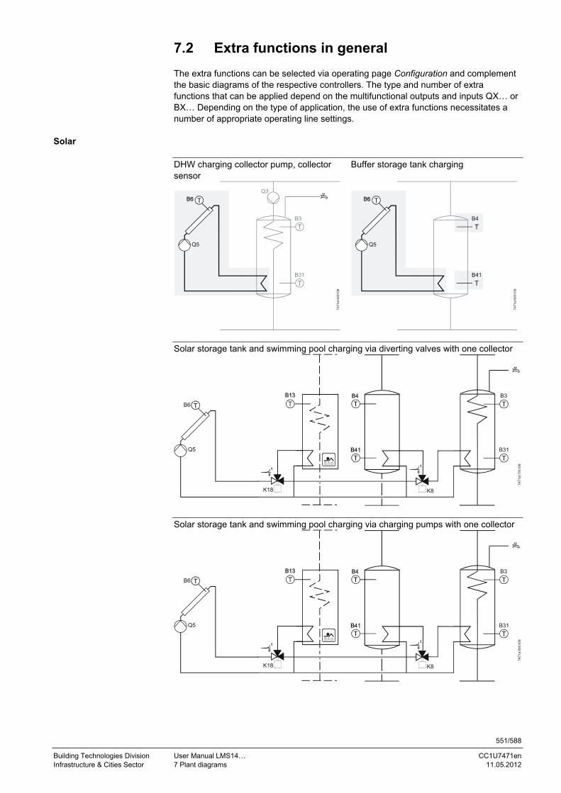
551/588
Building Technologies Division User Manual LMS14… CC1U7471en Infrastructure & Cities Sector 7 Plant diagrams 11.05.2012
7.2 Extra functions in general The extra functions can be selected via operating page Configuration and complement the basic diagrams of the respective controllers. The type and number of extra functions that can be applied depend on the multifunctional outputs and inputs QX… or BX… Depending on the type of application, the use of extra functions necessitates a number of appropriate operating line settings.
Solar
DHW charging collector pump, collector sensor
Buffer storage tank charging
747
1a1
4/01
09
Q3
B3
Q5
747
1a1
6/01
09
B4
Q5
Solar storage tank and swimming pool charging via diverting valves with one collector
7471
a17/
010
9
B3
B6
Q5
K8
1
0
K18
1
0
Solar storage tank and swimming pool charging via charging pumps with one collector 747
1a
18/
010
9
B3
B6
Q5
K8
1
0
K18
1
0

552/588
Building Technologies Division User Manual LMS14… CC1U7471en Infrastructure & Cities Sector 7 Plant diagrams 11.05.2012
Boiler
Boiler pump Bypass pump
747
1a19
/010
9
B2
Q1
T2
7471
a20/
010
9
B2
T2
Q12
Solid fuel boiler pump Return sensor
747
1a2
1/01
09
Q10
74
71a2
2/01
09
B2
T2
Flue gas temperature sensor
747
1a23
/010
9
B2
Q1
T2

553/588
Building Technologies Division User Manual LMS14… CC1U7471en Infrastructure & Cities Sector 7 Plant diagrams 11.05.2012
DHW storage tank (DHW)
DHW circulating pump Electric immersion heater for DHW
747
1a24
/01
09
B3
Q3
Q4
747
1a2
5/01
09
B3
Q3
K6
2nd DHW sensor DHW storage tank with external heat exchanger, charging pump, and intermediate circuit pump
747
1a2
6/01
09
Q3
747
1a27
/01
09
B3
Q3
B31
B36
Q33

554/588
Building Technologies Division User Manual LMS14… CC1U7471en Infrastructure & Cities Sector 7 Plant diagrams 11.05.2012
Buffer storage tank
Heat source shutoff valve buffer
747
1a2
8/01
09
B4
7471
a29/
0109
B4
Y4
Return diversion Partial tank charging 74
71a
30/0
109
Y15
1
0
B73
Y15
1
0
Storage tank charge transfer
747
1a32
/01
09
Q11
Heat converter
System pump Q14
Q14
747
1a3
3/01
09

555/588
Building Technologies Division User Manual LMS14… CC1U7471en Infrastructure & Cities Sector 7 Plant diagrams 11.05.2012
7.3 Extra functions with mixing group or extension module AVS75.39x…/AGU2.550...
The extra functions can be selected via operating page Function extension module 1 (6020), Function extension module 2 (6021), and Function extension module 3 (6022) and supplement the basic diagrams of the respective LMS14…
747
1a34
/010
9
Y5
B12
Q6
RG1/2
Q14
Y19
B15
747
1a35
/01
09
1st mixing heating circuit
2nd mixing heating circuit
3rd mixing heating circuit
Primary controller

556/588
Building Technologies Division User Manual LMS14… CC1U7471en Infrastructure & Cities Sector 7 Plant diagrams 11.05.2012
Key to mains voltage
Designation Description
T2 Burner 1st stage Release modulating burner
Q1 Boiler pump Q2 Heating circuit pump HC1 Q3 DHW charging pump/diverting valve Q4 Circulating pump Q5 Collector pump Q6 Heating circuit pump HC2 Q10 Solid fuel boiler pump Q11 Storage tank transfer pump Q12 Bypass pump Q14 System pump Q15 Consumer heating circuit pump VK1 Q18 Consumer heating circuit pump VK2 Q19 Swimming pool pump Q20 Heating circuit pump HC3 Q21/22/23 2nd pump stage HC pump 1-3 Q25 Cascade pump Q33 DHW intermediate circuit pump Q34 Instantaneous water heater pump Q35 DHW mixing pump Y1 1st heating circuit mixing valve opening Y2 1st heating circuit mixing valve closing Y4 Heat source shutoff valve Y5 2nd heating circuit mixing valve opening Y6 2nd heating circuit mixing valve closing Y11 3rd heating circuit mixing valve opening Y12 3rd heating circuit mixing valve closing Y15 Buffer return valve Y19 Primary controller mixing valve opening Y20 Primary controller mixing valve closing K6 Electric immersion heater DHW K8 Solar controlling element buffer K9 Solar pump external exchanger K10 Alarm output/alarm relay K13 Time program 5 K18 Solar controlling element swimming pool K27 Heat request K28 Refrigeration request K34 Water filling

557/588
Building Technologies Division User Manual LMS14… CC1U7471en Infrastructure & Cities Sector 7 Plant diagrams 11.05.2012
Key to low-voltage
Designation Description B1 Flow sensor heating circuit 1 B10 Common flow sensor B12 Flow sensor heating circuit 2 B13 Swimming pool sensor B2 Boiler sensor B22 Solid fuel boiler sensor B3 DHW sensor B31 DHW sensor B35 DHW flow sensor B36 DHW charging sensor B38 DHW outlet sensor B4 Buffer sensor B41 Buffer sensor B42 Buffer sensor B15 Flow sensor primary controller B39 DHW circulation sensor B6 Collector sensor B63 Solar flow sensor B64 Solar return sensor B7 Return sensor B70 Cascade return sensor B73 Common return sensor B8 Flue gas temperature sensor B9 Outside sensor RG1 Room unit 1 RG2 Room unit 2 RG3 Room unit 3 FS Flow switch

558/588
Building Technologies Division User Manual LMS14… CC1U7471en Infrastructure & Cities Sector 8 Technical data 11.05.2012
8 Technical data 8.1 LMS14… basic unit
8.1.1 General data
Mains voltage (rated voltage) AC 230 V
Mains frequency 50 Hz to DIN EN 298
Power consumption
- Operation Max. 14 W
- Power pack Max. 14 W
Rated surge voltage category III (as per DIN EN 60664)
Degree of protection IP00 IP40 (to be ensured when fitted inside the boiler)
Safety class Parts of safety class 0 and of PELV
Degree of pollution 2
Software classes As per DIN EN 60730-2-5 - Controller part Class A - Burner control Class C Dimensions (L x W x D) 230 x 150 x 30 mm Weight Approx. 0.254 kg Unit fuse 2 x T6.3H250 internal Mounting position Optional
Caution! When making 100% inspections as per DIN EN 60335-1, Addendum A, only AC voltage may be applied. If DC voltage tests are conducted, the LMS14... can get damaged.
8.1.2 Environmental conditions
Storage DIN EN 60721-3-1
- Climatic conditions Class 1K3
- Mechanical conditions Class 1M2
- Temperature range -20...60 °C
- Humidity <90% r.h. (noncondensing)
Transport DIN EN 60068-2 and DIN EN 60731-3-2
- Climatic conditions Class 2K3
- Mechanical conditions Class 2M2
- Temperature range -20...60 °C
- Humidity <90% r.h. (noncondensing) Operation DIN EN 60721-3-3 - Climatic conditions Class 3K3 - Mechanical conditions Class 3M2 - Temperature range 0...60 °C - Humidity <85% r.h. (noncondensing) - Vibrations EN 298/DIN EN 60068-2
Warning! Condensation, formation of ice and ingress of water are not permitted!

559/588
Building Technologies Division User Manual LMS14… CC1U7471en Infrastructure & Cities Sector 8 Technical data 11.05.2012
8.1.3 Electrical connections Total current all mains components connected to LMS14... and clipins
5 A (at UMains = AC 230 V; Ta = 25 °C)
Mains extension AUX1/AUX2 - Voltage AC 230 V - Current Depending on current draw of heating
circuit pump, programmable AC 230 V output, fuel valve, DHW charging pump, external ignition module and clipins used
QX1 - Voltage AC 230 V +10%/-15% - Current 5 mA…1 A, cos >0.8 - Cable length 120 m QX2 - Voltage AC 230 V +10%/-15% - Current 5 mA…1 A, cos >0.8 - Cable length 120 m QX3 - Voltage AC 230 V +10%/-15% - Current 5 mA…1 A, cos >0.8 - Cable length 120 m Flame supervision/ionization probe - Switching thresholds Min. 0.8 µA (required DC current) - Current Typically 4 µA, max. 10.5 µA - Response time in the event of loss of flame
1 s
- Physical contact The ionization probe and its connections must be located such that adequate protection against direct or indirect contact with active parts is ensured in every unfavorable position allowed under correct usage conditions
- Cable length for flame detector 1 m
Note! Conductors L- and N are interchangeable!
Safety limit thermostat - Voltage AC 230 V - Current 5 mA...1 A, cos >0.6
Carrying power to the fuel valve and ignition
- Cable length 3 m Fuel valve - AC output AC 230 V +10%/-15%
Valve must still open at AC 175 V - Current 5 mA…0.5 A, cos >0.6
Note! A fuel valve with rectifier may be connected to the fuel valve output only if
approved by Siemens! In this case, additional protective measures inside the LMS14... must be taken
(optional components)
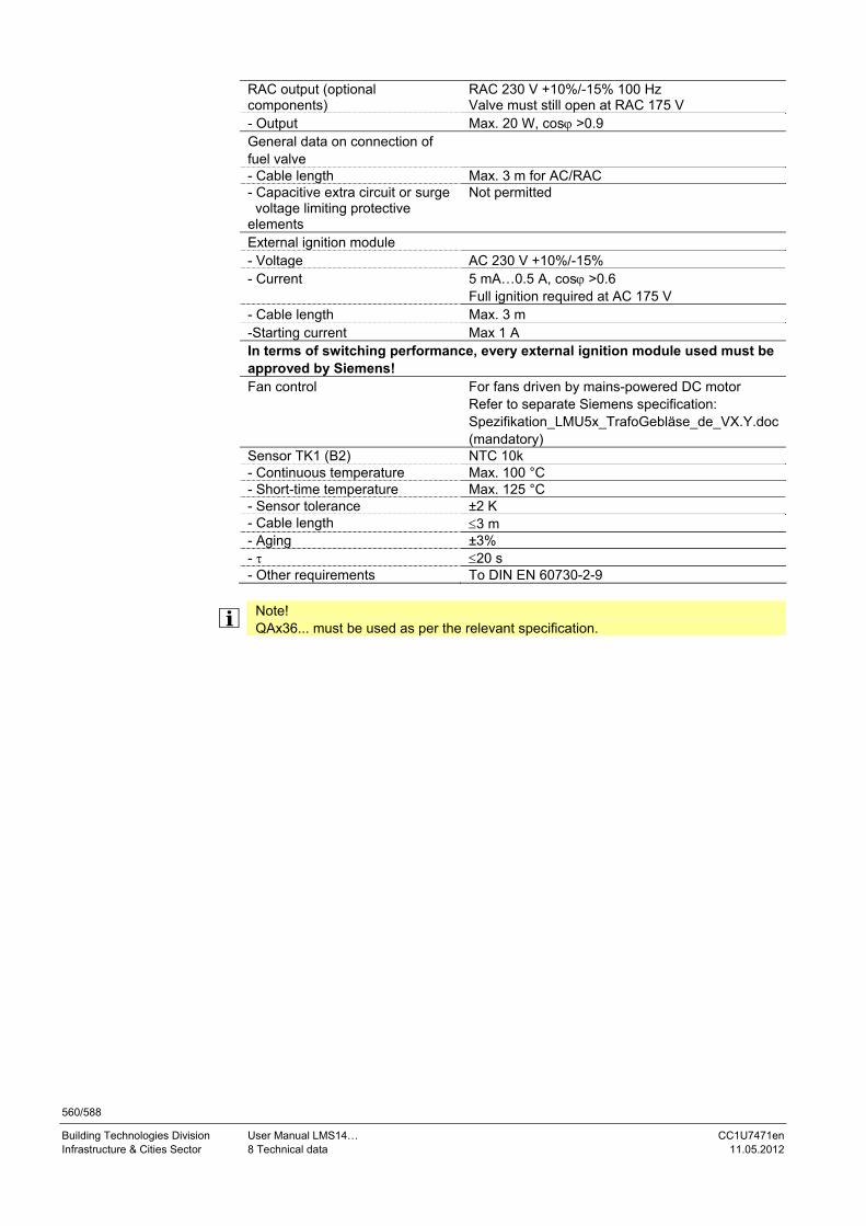
560/588
Building Technologies Division User Manual LMS14… CC1U7471en Infrastructure & Cities Sector 8 Technical data 11.05.2012
RAC output (optional components)
RAC 230 V +10%/-15% 100 Hz Valve must still open at RAC 175 V
- Output Max. 20 W, cos >0.9 General data on connection of fuel valve
- Cable length Max. 3 m for AC/RAC - Capacitive extra circuit or surge voltage limiting protective elements
Not permitted
External ignition module
- Voltage AC 230 V +10%/-15% - Current 5 mA…0.5 A, cos >0.6
Full ignition required at AC 175 V - Cable length Max. 3 m -Starting current Max 1 A In terms of switching performance, every external ignition module used must be approved by Siemens! Fan control For fans driven by mains-powered DC motor
Refer to separate Siemens specification: Spezifikation_LMU5x_TrafoGebläse_de_VX.Y.doc (mandatory)
Sensor TK1 (B2) NTC 10k - Continuous temperature Max. 100 °C - Short-time temperature Max. 125 °C - Sensor tolerance ±2 K - Cable length 3 m - Aging ±3% - 20 s - Other requirements To DIN EN 60730-2-9
Note! QAx36... must be used as per the relevant specification.

561/588
Building Technologies Division User Manual LMS14… CC1U7471en Infrastructure & Cities Sector 8 Technical data 11.05.2012
8.1.4 Low-voltage side 8.1.4.1. Inputs B7/BX4 Sensor (B7)/multifunctional sensor BX4 (X4) - Resistance value - Sensor (B7) NTC 10k
Refer to boiler sensor - Multifunctional sensor (BX4) NTC 10k (QAZ36…, QAD36…)
NTC 20k (flue gas sensor) Pt1000 optional for collector sensor and flue gas sensor)
- Cable length 3 m
Note! Sensor input BX4 is firmly assigned to sensor B7. Reading in of sensor B7 is safety-related.
8.1.4.2. Inputs B3/B38 Sensor B3/B38 (X5) - Resistance value NTC 10k - Cable length 10 m (when connecting a thermostat to
the input for the DHW sensor, high-quality thermostat contact material is required (e.g. gold-plated contacts), since signal voltage at this input is DC 5 V)
8.1.4.3. Inputs BX1/BX2/BX3 Sensor inputs BX1…BX3 (X5) - Resistance value NTC 10k (QAZ36…, QAD36…)
NTC 20k (flue gas sensor) Pt1000 (optional for collector sensor and flue gas sensor)
- Cable length 120 m Observe cross-sectional area of wires!(Refer to chapter Cross-sectional area sensors)
8.1.4.4. Input B9 Sensor B9 (X5) - Resistance value NTC 1k
Refer to specification QAC34… - Cable length 120 m
Observe cross-sectional area of wires!(Refer to chapter Cross-sectional area sensors)

562/588
Building Technologies Division User Manual LMS14… CC1U7471en Infrastructure & Cities Sector 8 Technical data 11.05.2012
8.1.4.5. Input H1 Multifunctional input/pressure sensor (X6) - Output voltage LMS14... DC 15 V ±5% DC 5 V ±5% - Current Imax. 10 mA each input - Input voltage LMS14... DC 10 V - Analog input Safety extra low-voltage - Operating range DC 0…10 V - Input resistance >100 k - Digital input - Safety extra low-voltage for potential-free low-voltage contacts Voltage with contact open DC 15 V Voltage with contact closed DC 1.5 mA - Cable length 10 m 8.1.4.6. Input H3 Multifunctional input/pressure sensor (X4) - Output voltage LMS14... DC 15 V ±5% DC 5 V ±5% - Current Imax. 10 mA - Input voltage LMS14... DC 10 V - Analog input Safety extra low-voltage - Operating range DC 0…10 V - Input resistance >100 k - Digital input - Safety extra low-voltage for potential-free low-voltage contacts Voltage with open contact DC 15 V Voltage with closed contact DC 1.5 mA - Cable length 10 m 8.1.4.7. Input H4 Multifunctional input/pressure sensor (X6) - Output voltage LMS14... DC 15 V ±5% DC 5 V ±5% - Current Imax. 10 mA - Input frequency 0/1Hz … 1 kHz - Digital input - Safety extra low-voltage for potential-free low-voltage contacts Voltage with contact open DC 5 V Voltage with contact closed DC 2 mA Frequency input Duty cycle 10…90% ton ; toff >300 µs Resolution 0.1 Hz @ 1Hz…1kHz Rise/drop-out time 20 µs Cable length 10 m

563/588
Building Technologies Division User Manual LMS14… CC1U7471en Infrastructure & Cities Sector 8 Technical data 11.05.2012
8.1.4.8. Input H5 Multifunctional input/room thermostat (X6) - Voltage DC 5 V - Digital input - Safety extra low-voltage for potentialfree low-voltage contacts Voltage with contact open DC 5 V Voltage with contact closed DC 2 mA - Cable length 120 m
Observe cross-sectional area of wires!(Refer to chapter Cross-sectional area sensors)
8.1.4.9. Input H6
Multifunctional input/gas pressure switch (X5)
- Digital input
- Safety extra low-voltage for potential-free low-voltage contacts Voltage with contact open DC 5 V Voltage with contact closed DC 2 mA - Cable length 120 m
Observe cross-sectional area of wires!(Refer to chapter Cross-sectional area sensors)
8.1.4.10. Input H7
Multifunctional input/air pressure switch (X4)
- Digital input
- Safety extra low-voltage for potential-free low-voltage contacts Voltage with contact open DC 5 V Current with contact closed DC 2 mA - Cable length 10 m
8.1.4.11. Input for reset (EK)
Reset button (X4/X30)
Digital input Active upon short-circuit after low-voltage GND
- Safety extra low voltage for potential-free low-voltage contacts Voltage with contact open DC 5 V Current with contact closed DC 0.5 mA - Line length 1 m
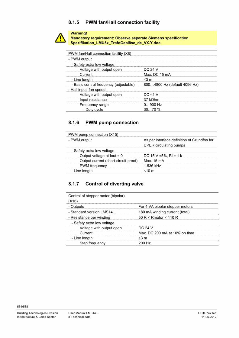
564/588
Building Technologies Division User Manual LMS14… CC1U7471en Infrastructure & Cities Sector 8 Technical data 11.05.2012
8.1.5 PWM fan/Hall connection facility
Warning! Mandatory requirement: Observe separate Siemens specification Spezifikation_LMU5x_TrafoGebläse_de_VX.Y.doc
PWM fan/Hall connection facility (X8)
- PWM output
- Safety extra low voltage Voltage with output open DC 24 V Current Max. DC 15 mA - Line length 3 m - Basic control frequency (adjustable) 800…4800 Hz (default 4096 Hz) - Hall input, fan speed Voltage with output open DC <1 V Input resistance 37 kOhm Frequency range - Duty cycle
0…900 Hz 30…70 %
8.1.6 PWM pump connection
PWM pump connection (X15)
- PWM output As per interface definition of Grundfos for UPER circulating pumps
- Safety extra low voltage Output voltage at Iout = 0 DC 15 V ±5%, Ri = 1 k Output current (short-circuit-proof) Max. 15 mA PWM frequency 1.536 kHz - Line length 10 m
8.1.7 Control of diverting valve
Control of stepper motor (bipolar) (X16)
- Outputs For 4 VA bipolar stepper motors
- Standard version LMS14... 180 mA winding current (total)
- Resistance per winding 50 R < Rmotor < 110 R
- Safety extra low voltage Voltage with output open DC 24 V Current Max. DC 200 mA at 10% on time - Line length 3 m Step frequency 200 Hz

565/588
Building Technologies Division User Manual LMS14… CC1U7471en Infrastructure & Cities Sector 8 Technical data 11.05.2012
8.1.8 BSB users BSB terminals (X7/X30/X50) - Operator unit AVS37… - Room unit QAA55.../QAA75… - Connection 2- or 3-wire - Cable length Max. 200 m at 1.5 mm² cross-sectional
area of cable - Cable resistance Max. 3 x 14 - Cross-sectional area of cable Min. 0.5 mm² - Users Max. 5 (1 operator unit, 3 room units,
1 service unit)
8.1.9 Cross-sectional area sensors
Cross-sectional area Maximum length
0.25 mm² 20 m
0.5 mm² 40 m
1 mm² 80 m
1.5 mm² 120 m

566/588
Building Technologies Division User Manual LMS14… CC1U7471en Infrastructure & Cities Sector 8 Technical data 11.05.2012
8.2 Parameter stick AGU2.56xx109
Degree of protection IP20
Safety class PELV ensured via LMS14.../LMS15...
Degree of contamination 2
Dimensions 60x20x12 mm (LxWxH)
Weight Approx. 16 g
Mounting position Optional
Life cycle Max. 300 h
Electrical data Mains supply DC 5 V ±5%
Warning! Use parameter stick only for setting the parameters on the LMS14.../LMS15... Do not plug it in during operation and do not use it for continuous operation!
Storage DIN EN 60721-3-1
- Climatic conditions Class 1K3
- Mechanical conditions Class 1M3
- Temperature range -20...60 °C
- Humidity <90% r.h. (noncondensing)
Transport DIN EN 60068-2 and DIN EN 60731-3-2
- Climatic conditions Class 2K3
- Mechanical conditions Class 2M2
- Temperature range -20...60 °C
- Humidity <90% r.h. (noncondensing) Operation DIN EN 60721-3-3 - Climatic conditions Class 3K3 - Mechanical conditions Class 3M2 - Temperature range 0...60 °C - Humidity <85% r.h. (noncondensing)
Warning! Condensation, formation of ice and ingress of water are not permitted!
Warning! The AGU2.56... may only be plugged into the respective socket on the LMS14.../LMS15... or OCI432...!
General unit data
Environmental conditions

567/588
Building Technologies Division User Manual LMS14… CC1U7471en Infrastructure & Cities Sector 8 Technical data 11.05.2012
8.3 Sensor characteristics
8.3.1 NTC 1k
T [°C] R [] T [°C] R [] T [°C] R []
-30 13034 0 2857 30 827
-29 12324 1 2730 31 796
-28 11657 2 2610 32 767
-27 11031 3 2496 33 740
-26 10442 4 2387 34 713
-25 9889 5 2284 35 687
-24 9369 6 2186 36 663
-23 8880 7 2093 37 640
-22 8420 8 2004 38 617
-21 7986 9 1920 39 595
-20 7578 10 1840 40 575
-19 7193 11 1763 41 555
-18 6831 12 1690 42 536
-17 6489 13 1621 43 517
-16 6166 14 1555 44 500
-15 5861 15 1492 45 483
-14 5574 16 1433 46 466
-13 5303 17 1375 47 451
-12 5046 18 1320 48 436
-11 4804 19 1268 49 421
-10 4574 20 1218 50 407
-9 4358 21 1170
-8 4152 22 1125
-7 3958 23 1081
-6 3774 24 1040
-5 3600 25 1000
-4 3435 26 962
-3 3279 27 926
-2 3131 28 892
-1 2990 29 859

568/588
Building Technologies Division User Manual LMS14… CC1U7471en Infrastructure & Cities Sector 8 Technical data 11.05.2012
8.3.2 NTC 10k
T [°C] R [] T [°C] R [] T [°C] R []
-30 175203 50 3605 130 298
-25 129289 55 2989 135 262
-20 96360 60 2490 140 232
-15 72502 65 2084 145 206
-10 55047 70 1753 150 183
-5 42158 75 1481 155 163
0 32555 80 1256 160 145
5 25339 85 1070 165 130
10 19873 90 915 170 117
15 15699 95 786 175 105
20 12488 100 677 180 95
25 10000 105 586 185 85
30 8059 110 508 190 77
35 6535 115 443 195 70
40 5330 120 387 200 64
45 4372 125 339
8.3.3 Pt1000
T [°C] R [] T [°C] R [] T [°C] R []
–30 882.2 50 1194 130 1498.3 –25 901.9 55 1213.2 135 1517.1 –20 921.6 60 1232.4 140 1535.8 –15 941.2 65 1251.6 145 1554.6 –10 960.9 70 1270.8 150 1573.3 –5 980.4 75 1289.9 155 1591.9 0 1000 80 1309 160 1610.5 5 1019.5 85 1328 165 1629.1
10 1039 90 1347.1 170 1647.7 15 1058.5 95 1366.1 175 1666.3 20 1077.9 100 1385.1 180 1684.8 25 1097.3 105 1404.0 185 1703.3 30 1116.7 110 1422.9 190 1721.7 35 1136.1 115 1441.8 195 1740.2 40 1155.4 120 1460.7 200 1758.6 45 1174.7 125 1479.5

569/588
Building Technologies Division User Manual LMS14… CC1U7471en Infrastructure & Cities Sector 8 Technical data 11.05.2012
8.3.4 NTC 20k
T [°C] R [] T [°C] R [] T [°C] R []
-50 1755765 70 3489 200 145
-40 818659 80 2515 2100 122
-30 406438 90 1845 220 103
-20 213261 100 1377 230 88
-10 117521 110 1043 240 76
0 67650 120 801 250 65
10 40491 130 624 260 57
20 25099 140 491 270 49
25 20000 150 392 280 43
30 16057 160 315 290 38
40 10569 170 256 300 34
50 7140 180 210
60 4938 190 174

570/588
Building Technologies Division User Manual LMS14… CC1U7471en Infrastructure & Cities Sector 9 List of figures 11.05.2012

571/588
Building Technologies Division User Manual LMS14… CC1U7471en Infrastructure & Cities Sector 9 List of figures 11.05.2012
9 List of figures Figure 1: Product range summary – wired.....................................................................17
Figure 2: Product range summary – wireless ................................................................17
Figure 3: Basic diagram.................................................................................................26
Figure 4: Dimensions of basic unit complete (Basic).....................................................27
Figure 5: Terminals of LMS14… complete ....................................................................28
Figure 6: Assignment of terminal X30 ...........................................................................29
Figure 7: Dimensions of basic unit complete (Medium).................................................31
Figure 8: Terminals of LMS14… complete ....................................................................32
Figure 9: Assignment of terminal X30 ...........................................................................33
Figure 10: Dimensions of basic unit complete (Deluxe) ................................................35
Figure 11: Terminals of LMS14… complete ..................................................................36
Figure 12: Assignment of terminal X30 .........................................................................37
Figure 13: Cable AGU2.110x109 ..................................................................................39
Figure 14: Dimension AGU2.56xx109 ...........................................................................40
Figure 15: Presence button .........................................................................................124
Figure 16: Setpoints.....................................................................................................125
Figure 17: Heating curve – heating curve slope ..........................................................126
Figure 18: Heating curve – heating curve displacement .............................................127
Figure 19: ECO function – summer/winter heating limit ..............................................129
Figure 20: Eco function – 24-hour heating limit ...........................................................130
Figure 21: Flow temperature setpoint limits.................................................................132
Figure 22: Room model ...............................................................................................139
Figure 23: Room temperature control and limitation ...................................................142
Figure 24: Boost heating .............................................................................................144
Figure 25: Optimum start/stop control .........................................................................147
Figure26: Raising the reduced setpoint .......................................................................149
Figure 27: Reduced setpoint increase end..................................................................150
Figure28: Floor curing function....................................................................................160
Figure29: Floor curing setpoint manually ....................................................................161
Figure30: Room temperature limitation .......................................................................169
Figure31: Nominal setpoint..........................................................................................172
Figure32: DHW release – 24h/day ..............................................................................174
Figure 33: DHW release – time programs HCs ...........................................................175
Figure 34: DHW release – time program 4/DHW ........................................................175
Figure 35: Overtemperature protection swimming pool temperature maximum..........186

572/588
Building Technologies Division User Manual LMS14… CC1U7471en Infrastructure & Cities Sector 9 List of figures 11.05.2012
Figure 36: Primary controller/system pump flow temperature setpoint minimum/maximum.............................................................................................. 187
Figure 37: Boiler setpoints .......................................................................................... 191
Figure 38: Boiler setpoints OEM ................................................................................. 192
Figure 39: Limitation of boiler temperature increase................................................... 203
Figure 40: Speed control – boiler setpoint .................................................................. 206
Figure 41: Pump speed as a function of burner output............................................... 208
Figure 42: Control of the boiler/burner ........................................................................ 214
Figure 43: Switching differentials ................................................................................ 216
Figure 44: Flue gas supervision.................................................................................. 223
Figure 45: Static water pressure supervision with LMS14… ...................................... 224
Figure 46: Dynamic water pressure supervision with LMS14... .................................. 228
Figure 47: Water pressure sensor .............................................................................. 231
Figure 48: Limitation of output – switching differential output reduction ..................... 236
Figure 49: Electronic limit thermostat – cutout temperature ....................................... 237
Figure 50: Deaeration phases..................................................................................... 243
Figure 51: Generation of boiler temperature setpoint ................................................. 251
Figure 52: Boiler control – modulating control ............................................................ 252
Figure 53: Protective boiler startup – calculation of locking signal ............................. 255
Figure 54: Charging controller – charging temperature minimum swimming pool ...... 268
Figure 55: Charging controller – charging temperature minimum buffer .................... 269
Figure 56: Maximum charging temperature, maximum safety temperature ............... 270
Figure 57: Collector start function – minimum run time collector pump ...................... 273
Figure 58: Collector start function – special case frost protection............................... 274
Figure 59: Frost protection for the collector ................................................................ 275
Figure 60: Overtemperature protection for the collector ............................................. 276
Figure 61: Recooling – recooling via the collector's surfaces ..................................... 278
Figure 62: Evaporation temperature of medium ......................................................... 280
Figure 63: Operating mode ......................................................................................... 284
Figure 64: Setpoints .................................................................................................... 286
Figure 65: Control of the boiler /burner – delta T controller ........................................ 287
Figure 66: Boiler/burner control – DHW storage tank ................................................. 288
Figure 67: Control of boiler/burner – buffer storage tank ............................................ 289
Figure 68: Overtemperature protection....................................................................... 291
Figure 69: Frost protection.......................................................................................... 292
Figure 70: Frost protection for the solid fuel boiler...................................................... 293
Figure 71: Automatic locks.......................................................................................... 295

573/588
Building Technologies Division User Manual LMS14… CC1U7471en Infrastructure & Cities Sector 9 List of figures 11.05.2012
Figure 72: Charging solar/solid fuel boiler ...................................................................296
Figure 73: Partial charging ..........................................................................................299
Figure 74: Release – Once/day...................................................................................305
Figure 75: Release – Once/day...................................................................................305
Figure 76: Release – Several times/day......................................................................305
Figure 77: Overtemperature protection........................................................................310
Figure 78: Electrode immersion heater – 24h / day.....................................................314
Figure 79: Electrode immersion heater – DHW release ..............................................314
Figure 80: Electrode immersion heater – Time program 4/DHW ................................315
Figure 81: DHW push ..................................................................................................317
Figure 82: Boiler pump – Speed control depending on the boiler temperature setpoint.............................................................................................................................372
Figure 83: Inputs Hx - Flow measurement Hz .............................................................392
Figure 84: Inputs Hx – heat request ............................................................................395
Figure 85: Inputs Hx – pressure measurement ...........................................................395
Figure 86: Extensions module – limit thermostat HC ..................................................398
Figure 87: H2 extension module..................................................................................410
Figure 88: H2 extension module – heating demand....................................................413
Figure 89: Input Hx H2 extension module – NO contact ............................................414
Figure 90: Building room model – attenuated outside temperature.............................418
Figure 91: Building room model – setpoint compensation...........................................419
Figure 92: Frost protection for the plant.......................................................................420
Figure 93: Plant diagrams – check no. heating circuits ...............................................442
Figure 94: Error message functions – boiler temperature alarm .................................455
Figure 95: Sequence diagram for burner capacities ≤120 kW ....................................505
Figure 96: Sequence diagram for burner capacities ≥120 kW ....................................506
Figure 97: Safety time TSA..........................................................................................512
Figure 98: Block circuit diagram Pt1 speed-setpoint filter ...........................................518
Figure 99: Setpoint filter in phases TI and MOD..........................................................520
Figure 100: Setpoint filter in phases other than TI and MOD ......................................520
Figure 101: Setpoint filter in all phases .......................................................................521
Figure 102: Supervision of air supply by monitoring the current fan speed – limitation of PWM.....................................................................................................................524
Figure 103: Fan parameters settable as load values via QAA75…/AVS37….............527
Figure 104: Fan parameters settable as load values via QAA75…/AVS37… - presetting the speed value via the operator terminal ............................................................528
Figure 105: Fan parameters settable as load values via QAA75…/AVS37…- presetting load values via the operator terminal ...................................................................529

574/588
Building Technologies Division User Manual LMS14… CC1U7471en Infrastructure & Cities Sector 9 List of figures 11.05.2012
Figure 106: Fan parameters settable as load values via QAA75…/AVS37…- load range............................................................................................................................. 531
Figure 107: Fan parameters settable as load values via QAA75…/AVS37…- limits .. 532

575/588
Building Technologies Division User Manual LMS14… CC1U7471en Infrastructure & Cities Sector Index 11.05.2012
Index 1
1st phase off..........................................................117 1st phase on ..........................................................117 2
24-hour heating limit.............................................130 2nd phase off.........................................................117 2nd phase on .........................................................117 3 3rd phase off .........................................................117 3rd phase on..........................................................117 A
Abs SwiOffCondAquaB...........................................357 Abs TempSwiOffThresh..........................................357 Action changeover functions ......................165, 448 Actuator running time ..................................158, 188 Actuator type .................................................157, 188 Additional settings for dynamic pressure supervision................................................................................248 Additional settings for static pressure supervision ..247 AGU2.11x109
Mounting and installation .................................39 AGU2.56
Canceled checks .............................................465 Checks via LMS14 ...........................................464 General notes/risks/problems ........................467 Human failure...................................................467 Introduction......................................................464 OEM parameter set group number/OEM boiler type ...................................................................465 Operation via boiler .........................................468 Parameter setting state ...................................472 Potential risks ..................................................465 Reducing risks .................................................465 Restrictions ......................................................467 Safety-related parameters ..............................467 Selecting data set ............................................469 selecting stick operations ..............................469 Settings in detail ..............................................464 Spare part business ........................................466 Transfer data between LMS14/parameter stick...........................................................................473 Wrong use and risks .......................................464
AGU2.56xx109 Dimensions ........................................................40
AGU2.56XX109 Environmental conditions ..................................566 General unit data .............................................566 Technical data..................................................566
Alarm delay............................................................446 Antifreeze...............................................................282 Antifreeze concentration ......................................282 Aqua booster.................................................346, 354 Aqua booster Ge ...................................................355
Auto deaeration procedure ..................................244 Auto generation lock ............................................294 Auto heat gen lock SD ..........................................294 Auto source seq ch'over..........................................261 Auto source seq exclusion ......................................262 Automatic push .....................................................317 AVS75.39X/AGU2.550
Key - low-voltage ...............................................557 Key - mains voltage ...........................................556 Mixing heating circuit ......................................555 Plant diagrams .................................................555 Primary controller ............................................555
B
Basic pos DHW div valve .....................308, 347, 366 Basic units
Checking the LED ..............................................41 Binding ...................................................................115 Boiler
Boiler pump ......................................................201 Burner control ..................................................196 Control of the boiler ........................................214 Dearation function ...........................................243 Delay heat request special operation ............220 Dynamic pressure supervision ......................226 Dynamic switching differentials .....................216 Electronic limit thermostat .............................237 Electronic safety limit thermostat ..................238 Electronic temperature controller ..................202 Fan ....................................................................212 Filling/flow supervision ...................................232 Flue gas supervision .......................................221 Frost protection ...............................................194 Full charging of buffer storage tank ..............190 Input configuration flow supervision.............246 Limitation of boiler temperature increase .....203 Limitation of output .........................................235 Minimum limitation of boiler temperature .....198 Minimum limitation of return temperature ....200 Output data.......................................................211 Overtemperature protection ...........................197 PID control algorithm ......................................195 Quick shutdown of burner ..............................234 Release threshold outside temperature ........190 Setpoint manual control..................................193 Setpoints ..........................................................191 Speed control ...................................................205 Static pressure supervision............................224 Water pressure sensor ....................................230
Boiler control Modulating control .............................................252
Boiler pump Basics ...............................................................371
Boiler pump on heat gen lock..................................201
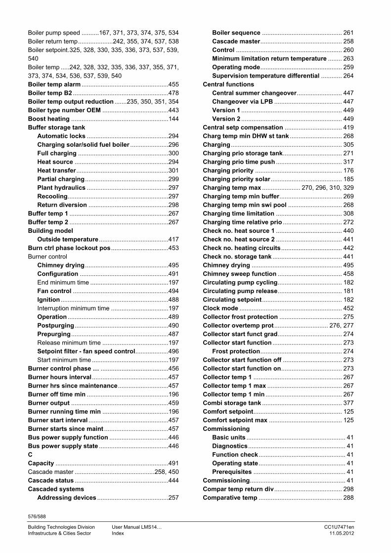
576/588
Building Technologies Division User Manual LMS14… CC1U7471en Infrastructure & Cities Sector Index 11.05.2012
Boiler pump speed ..........167, 371, 373, 374, 375, 534 Boiler return temp....................242, 355, 374, 537, 538 Boiler setpoint.325, 328, 330, 335, 336, 373, 537, 539, 540 Boiler temp .....242, 328, 332, 335, 336, 337, 355, 371, 373, 374, 534, 536, 537, 539, 540 Boiler temp alarm ..................................................455 Boiler temp B2 .......................................................478 Boiler temp output reduction .......235, 350, 351, 354 Boiler type number OEM ......................................443 Boost heating ........................................................144 Buffer storage tank
Automatic locks ...............................................294 Charging solar/solid fuel boiler ......................296 Full charging ....................................................300 Heat source ......................................................294 Heat transfer .....................................................301 Partial charging................................................299 Plant hydraulics ...............................................297 Recooling..........................................................297 Return diversion ..............................................298
Buffer temp 1 .........................................................267 Buffer temp 2 .........................................................267 Building model
Outside temperature ........................................417 Burn ctrl phase lockout pos .................................453 Burner control
Chimney drying ................................................495 Configuration ...................................................491 End minimum time .............................................197 Fan control .......................................................494 Ignition ..............................................................488 Interruption minimum time .................................197 Operation ..........................................................489 Postpurging......................................................490 Prepurging ........................................................487 Release minimum time ......................................197 Setpoint filter - fan speed control...................496 Start minimum time ............................................197
Burner control phase … .......................................456 Burner hours interval ............................................457 Burner hrs since maintenance .............................457 Burner off time min ...............................................196 Burner output ........................................................459 Burner running time min ......................................196 Burner start interval ..............................................457 Burner starts since maint .....................................457 Bus power supply function ..................................446 Bus power supply state ........................................446 C Capacity .................................................................491 Cascade master ..............................................258, 450 Cascade status ......................................................444 Cascaded systems
Addressing devices .........................................257
Boiler sequence .............................................. 261 Cascade master............................................... 258 Control ............................................................. 260 Minimum limitation return temperature ........ 263 Operating mode............................................... 259 Supervision temperature differential ............ 264
Central functions Central summer changeover.......................... 447 Changeover via LPB ....................................... 447 Version 1 .......................................................... 449 Version 2 .......................................................... 449
Central setp compensation ................................. 419 Charg temp min DHW st tank .............................. 268 Charging ................................................................ 305 Charging prio storage tank.................................. 271 Charging prio time push ...................................... 317 Charging priority .................................................. 176 Charging priority solar ......................................... 185 Charging temp max ...................... 270, 296, 310, 329 Charging temp min buffer.................................... 269 Charging temp min swi pool ............................... 268 Charging time limitation ...................................... 308 Charging time relative prio .................................. 272 Check no. heat source 1 ...................................... 440 Check no. heat source 2 ...................................... 441 Check no. heating circuits ................................... 442 Check no. storage tank ........................................ 441 Chimney drying .................................................... 495 Chimney sweep function ..................................... 458 Circulating pump cycling..................................... 182 Circulating pump release..................................... 181 Circulating setpoint.............................................. 182 Clock mode ........................................................... 452 Collector frost protection .................................... 275 Collector overtemp prot ............................... 276, 277 Collector start funct grad..................................... 274 Collector start function ........................................ 273
Frost protection............................................... 274 Collector start function off .................................. 273 Collector start function on................................... 273 Collector temp 1 ................................................... 267 Collector temp 1 max ........................................... 267 Collector temp 1 min ............................................ 267 Combi storage tank .............................................. 377 Comfort setpoint................................................... 125 Comfort setpoint max .......................................... 125 Commissioning
Basic units ......................................................... 41 Diagnostics ........................................................ 41 Function check .................................................. 41 Operating state .................................................. 41 Prerequisites ..................................................... 41
Commissioning....................................................... 41 Compar temp return div....................................... 298 Comparative temp ................................................ 288

577/588
Building Technologies Division User Manual LMS14… CC1U7471en Infrastructure & Cities Sector Index 11.05.2012
Comparison temp transfer ...........................302, 321 Compensation variants
Generation - compensation variant ...............122 Config reaction LT/SLT ...........................................499 Configuration
Boiler ................................................................370 Boiler pump......................................................370 Building model.................................................417 BX extension modules ....................................405 Combi storage tanks .......................................377 Device data.......................................................443 DHW separate circuit ......................................367 DHW storage tank............................................364 EX extension modules ....................................398 Extension modules..........................................396 Flue gas damper ..............................................421 Frost protection - plant ...................................420 H2 extension modules ....................................407 Heating circuits................................................363 Inputs HX ..........................................................386 Instantaneous water heater ............................346 Manual setting .................................................363 Plant diagrams .................................................439 Pressure measurements HX ...........................422 Pump/valve kick...............................................421 PWM output P1 ................................................415 QX extension modules ....................................400 Relay outputs QX.............................................378 Saving the sensors..........................................424 Sensor inputs BX.............................................384 Setpoint compensation ...................................419 Solar..................................................................376
Configuration ........................................................416 Contact state H1....................................................479 Contact state H2 module 1 ...................................479 Contact state H2 module 2 ...................................479 Contact state H2 module 3 ...................................479 Contact state H3....................................................479 Contact state H4....................................................479 Contact state H5....................................................479 Contact state H6....................................................479 Contact state H7....................................................479 Contact type H2 module 1 ....................................412 Contact type H2 module 2 ....................................412 Contact type H2 module 3 ....................................412 Contact type Hx.....................................................393 Continuous pump operation ................................151 Control of the boiler/burner
Buffer storage tank..........................................289 Delta T-controller ...............................................287 DHW storage tank............................................288 Flow temperature setpoint..............................289 Minimum setpoint ............................................290
Control sensor keep hot...............................344, 352 Controller delay.....................................................215
Controller delay duration .....................................215 Controller delay speed .................................215, 528 Controller stop function .......................................462 Controller stop setpoint .......................................462 Cooling circuit 1
Operating mode ...............................................168 Room temperature limitation ..........................169 Setpoints ..........................................................168
Cooling circuit 1, 2, 3 ............................................363 Ctrl boiler pump/DHW valve .................................370 Ctrl boiler pump/DHW valve....................................205 Ctrl boiler pump/DHW valve....................................538 Current fan control................................................486 Current phase number..........................................486 Curve readj at 50% speed.....................................164 Curve readj at 50% speed.......................................534 Curve readj at 50% speed.......................................536 CustomerNo_ParaSet .............................................548 Cutout temp LT..............................................202, 237 D D’t care tr Ret ab Fl .......................................240, 242 D’t care trans TGrad......................................240, 242 Day/month..............................................................114 Deaeration function ......................................245, 463 Deaeration time DHW............................................245 Deaeration time heat circuit .................................245 Default values ........................................................117 Delay heat request ................................................137 Delay heat request during special operation .....220 Delay pump off ................................................347, 365 Delay secondary pump .........................................272 Delay speed ctrl HC1 ......................................534, 536 Delay speed ctrl HCx ..............................................166 Delete all devices ..................................................116 Der action time Tv DHW .......................................195 Der action time Tv HCs .........................................195 Development index ...............................................443 Device address ......................................................445 Device family .........................................................443 Device identification .............................................443 Device variant ........................................................443 DHW assignment...................................................450 DHW charging alarm .............................................454 DHW charging priority ..........................................184 DHW charging temp........................335, 336, 339, 340 DHW consumption temp .........350, 351, 352, 355, 359 DHW controlling element .....................308, 346, 365 DHW flow .......................................................341, 392 DHW heating
Charging - controllable heat sources ............170 Charging - uncontrolled heat sources ...........170 Circulating pump .............................................181 DHW mode........................................................171 DHW release .....................................................174 Forced signals .................................................177

578/588
Building Technologies Division User Manual LMS14… CC1U7471en Infrastructure & Cities Sector Index 11.05.2012
Frost protection ...............................................182 Holiday program ..............................................173 Legionella function ..........................................178 Locking signals ................................................176 Operating mode changeover ..........................183 Priority ..............................................................176 Pump overrun...................................................177 Setpoints...........................................................172
DHW sensor ....................................................346, 364 DHW separate circuit ............................................367 DHW storage tank
Charging control ..............................................307 Charging pump/diverting valve ......................308 DHW charging 1 sensor ..................................303 DHW charging 2 sensors ................................304 DHW charging thermostat...............................304 DHW push .........................................................316 Discharging protection....................................309 Electric immersion heater ...............................313 Excess heat draw .............................................318 Frost protection ...............................................311 Heat request .....................................................303 Heat transfer .....................................................321 Limitation of charging time .............................308 Overtemperature protection ...........................310 Plant hydraulics ...............................................318 Recooling..........................................................312 Release .............................................................305 Speed-controlled pump ...................................319 Stratification storage tank/intermediate circuit...........................................................................322
DHW temp 1 ...267, 325, 329, 330, 335, 336, 339, 340 DHW temp 2....................................325, 329, 335, 339 DHW temp B3/B38 .................................................478 DHW temp setpoint 325, 328, 329, 330, 332, 335, 336, 337, 339, 340, 355 Diagnostics of heat sources
Process values.................................................486 Diff SetpFiltTmeConst .............................................496 Direct control - DHW charging temperature
Full charging ....................................................338 Recharging .......................................................340
Discharging protection .........................................309 Display system messages ....................................446 Duration chimney drying ......................................495 DV DHW st length ph ..............................................369 DV DHW st length ph2 ..........................................369 DV DHW st length ph3 ..........................................369 DV DHW step time ph1..........................................368 DV DHW step time ph2..........................................368 DV DHW step time ph3..........................................368 DV DHW steps ph1 ................................................368 DV DHW steps ph2 ................................................368 DV DHW steps ph3 ................................................368 Dyn press superv sh'down...................................226
Dyn press superv time ......................................... 226 Dyn press superv time const .............................. 226 Dyn press supervision ................................. 229, 246 Dyn PressSup AutoAct ................................ 229, 248 Dyn PressSup Pause.................................... 229, 248 Dyn PressSup WarnOffset ........................... 229, 248 Dyn PressSupPumpDelay............................ 229, 248 Dyn PressSupRepet ..................................... 229, 248 Dyn SD on setpoint change ................................. 219 Dyn SD when burner on ....................................... 220 Dyn SD with HC/DHW change ............................. 219 Dyn superv press diff max................................... 226 Dyn superv press diff min ................................... 226 Dyn superv press increase .................................. 226 Dynamic pressure supervision
Basics............................................................... 227 E El imm heater optg mode..................................... 313 El immersion heater control ................................ 315 El immersion heater release ................................ 314 Electronic safety limit thermostat
Basics............................................................... 238 Error handling ................................................. 238 Error handling routines...................................... 242 List of error/error reactions................................ 239 Supervisory functions .................................... 241
End ......................................................................... 118 End of summertime .............................................. 114 Environmental compatibility
Disposal ............................................................. 21 Error code … ......................................................... 456 Evaporation heat carrier ...................................... 280 EX extension modules
Operating state ................................................ 399 Excess heat discharge ......................................... 291 Excess heat draw ................................. 162, 184, 318 Excess interm circ temp del ................................ 323 Excess interm circ temp max .............. 322, 335, 339 Ext source with eco mode ................................... 450 Ext’n 24-hour heating limit .................................. 131 External solar exchanger ..................................... 376 Extra functions in general
Boiler ................................................................ 552 Buffer storage tank ......................................... 554 DHW storage tank ........................................... 553 Heat converter ................................................. 554 Solar ................................................................. 551
F Fan output/speed slope ............................... 494, 528 Fan output/speed Y-section.................................... 528 Fan output/speed Y-section) ............................... 494 Fan parameters
Ionization current maintenance ..................... 533 Limitation - ionization current........................ 533 Presetting load values....................................... 529

579/588
Building Technologies Division User Manual LMS14… CC1U7471en Infrastructure & Cities Sector Index 11.05.2012
Fan PWM max........................................................497 Fan PWM max high-fire ........................................499 Fan PWM max ignition..........................................499 Fan PWM max prepurg .........................................499 Fan PWM min ........................................................497 Fan PWM min ignition ..........................................499 Fan PWM min low-fire...........................................499 Fan PWM min prepurg ..........................................498 Fan shutdown delay .............................................213 Fan shutdown heating mode ...............................212 Fan sp start value inst WH ...........................212, 528 Fan speed .......................................................375, 486 Fan speed control
Speed limits .......................................................517 Fan speed DHW max..............328, 335, 336, 340, 528 Fan speed DHW max ............................................212 Fan speed full charging max ...............212, 339, 528 Fan speed heating max ................................212, 528 Fan speed ionization current ...............................457 Faults
Acknowledgements .........................................453 Error message functions ................................454 History ..............................................................456 Message ...........................................................453
Filter time const speed ctrl ..164, 534, 536, 539, 540 Fl’g superv time con rel mod ...............................221 Floor curing day current ......................................161 Floor curing function............................................159
Modulating pump ...............................................161 Floor curing setp current .....................................161 Floor curing setp manually ..................................161 Flow setp compensation delay....322, 332, 335, 337 Flow setp compensation Tn.........................322, 335 Flow setp compensation Tv.........................323, 335 Flow setp compensation XP ........................322, 335 Flow setp readj speed ctrl ....................164, 534, 536 Flow setpoint boost .....307, 328, 330, 335, 341, 350, 351, 354 Flow supervision...........................................246, 348 Flow switch shutdown..........................................232 Flow switch time cons ..........................344, 347, 352 Flow temp 1 alarm ..........................................155, 454 Flow temp 2 alarm ..........................................155, 454 Flow temp 3 alarm ..........................................155, 454 Flow temp setp cons request ..............................184 Flow temp setp swi pool ......................................184 Flow temp setpoint max ...............................132, 187 Flow temp setpoint min ................................132, 187 Flow temp setpoint room stat ..............................133 Flow temperature setpoint limits
Maximum ..........................................................132 Minimum ...........................................................132
Flue gas superv shutdown...................................221 Flue gas superv st prev tme ................................221 Flue gas supervision
Check of sensor.................................................221 Function .............................................................222
Flue gas temp output limit ...................................221 Flue gas temp output red .....................................221 Flue gas temp swi-off limit ...................................221 Forced charging ....................................303, 304, 306 Forced prepurging on error .................................493 Forced time basic stage ..........................................260 Foresee time DHW prio.........................................323 Forward shift charging .........................................305 Freigabe QAA GebläsePara .................................498 Frequency H4 ................................................392, 479 Frequency value 1 H4 .....................................348, 394 Frequency value 2 H4 .....................................348, 394 Frost prot plant boiler pump ........................201, 292 Buffer storage tank ...............................................300 Frost protection - plant
Minimum pump speed .......................................420 Frost protection flow temp.......................................152 Frost protection plant ...........................................420 Frost protection setpoint......................................125 Full charging..........................................................300 Full charging buffer .................................................190 Full charging sensor .............................................300 Full charging temp min.........................................300 Full charging with B36 ..........323, 332, 335, 337, 339 Funct input EX21 module x ..................................398 Funct value 1 H2 module 1 ...........................230, 413 Funct value 1 H2 module 2 ...........................230, 413 Funct value 1 H2 module 3 ...........................230, 413 Funct value 2 H2 module 1 ...........................230, 413 Funct value 2 H2 module 2 ...........................230, 413 Funct value 2 H2 module 3 ...........................230, 413 Function extension module x ..............................396 Function input H1..........................................230, 348 Function input H2 module 1 .................................230 Function input H2 module 2 .................................230 Function input H2 module 3 .................................230 Function input H3..........................................230, 348 Function input H4 ....................................................348 Function input H5 ....................................................348 Function input H6 ....................................................348 Function input H7 ....................................................348 Function of input H2 module 1 ............................407 Function of input H2 module 2 ............................407 Function of input H2 module 3 ............................407 Function of input Hx .............................................386 Function output P1 .......................................415, 538 Function value 1 H1 ......................................230, 394 Function value 1 H3 ......................................230, 394 Function value 1 H4 ........................................348, 394 Function value 2 H1 ......................................230, 394 Function value 2 H3 ......................................230, 394 Function value 2 H4 ........................................348, 394

580/588
Building Technologies Division User Manual LMS14… CC1U7471en Infrastructure & Cities Sector Index 11.05.2012
G
GP configuration ...................................................492 Gradient end cons.................................................342 Gradient start cons ...............................................342 Gradient start cons keep hot................................342 H H2 extension modules
Operating state.................................................411 Hall sensor pulses/rev ..........................................493 Handling ...................................................................42
Operation and display .......................................42 Overview of settings..........................................43
Heat transfer Time of heat transfer .......................................301 Transfer sensor/temperature level .................302 Via charging pump Q3 .....................................301 Via combi storage tank....................................302 Via transfer pump Q11.....................................301
Heat up gradient ............................................139, 148 Heating circuit 1, 2, 3 ............................................363 Heating circuits
2-speed boiler pump ........................................167 2-speed hearing circuit pump .........................166 Behavior............................................................166 Boost heating ...................................................144 Buffer storage tank/primary controller ..........162 Compensation variants ...................................122 Continuous pump operation ...........................151 Delay heat request ...........................................137 ECO function ....................................................129 Floor curing function.......................................159 Flow temperature alarm ..................................155 Flow temperature setpoint limits....................132 Forced signal and locking signal ...................162 Forced signals..........................................154, 156 Frost protection ...............................................152 Heating curve ...................................................126 Heating limit room controller ..........................143 Heating up gradient room model....................148 Locking signals ........................................154, 156 Mixing valve control ........................................157 Occupancy button ...........................................124 Operating level .................................................124 Operating level changeover ............................165 Operating mode ...............................................120 Operating mode changeover ..........................165 Optimum start/stop control.............................147 Overtemperature protection ...................153, 154 Pulse lock .........................................................155 Quick setback...................................................145 Raising the reduced setpoint..........................149 Room influence ................................................140 Room model .....................................................139 Room temperature control and limitation .....142 Room thermostat .............................................133
Setpoints .......................................................... 125 Speed-controlled pump .................................. 163
Heating curve Calculation ........................................................ 127
Heating curve adaption........................................ 128 Heating curve displacement ................................ 127 Heating curve slope ............................................. 126 Heating limit room controller ...................... 143, 535 HF outp OEM limit .................................................. 502 History …............................................................... 456 Home run mode .................................................... 492 Hours run collect overtemp ................................. 282 Hours run collector pump.................................... 282 Hours run solar yield............................................ 282 Hours/minutes ...................................................... 114 HQ PStickDataSetNo ............................................ 471 I Ign outp OEM limit .................................................. 502 Impact heat generation lock ................................ 201 Info 1 OEM ............................................................. 443 Info 2 OEM ............................................................. 443 Input configuration dynamic pressure supervision................................................................................ 246 Input EX21 module 1 .................................... 399, 479 Input EX21 module 2 .................................... 399, 479 Input EX21 module 3 .................................... 399, 479 Input/output test
Input test EX .................................................... 479 Input test HX .................................................... 479 Input test sensors ........................................... 478 Output test relay.............................................. 476
Inputs HX Frequency value/function value ........................ 392
Instant WH setpoint ................ 350, 351, 352, 355, 359 Instantaneous water heater
Configuration................................................... 346 Control ............................................................. 341 DHW consumption .................................. 341, 342 Keep hot function............................................ 343 Overrun ............................................................ 344 Sensor failure .................................................... 341 Setpoint readjustment .................................... 359 Speed-controlled pump .................................. 345 Times ................................................................ 344
Int action time Tn DHW ........................................ 195 Int action time Tn HCs.......................................... 195 Integr dyn WaterPress ......................................... 229 Interm circ boost recharging ....................... 322, 340 Intermediate circuit boost............ 322, 335, 336, 339 Interv burner off time .............................................. 357 Interv burner on time .............................................. 357 Interv outp increase ............................................. 357 Ion curr level extran light..................................... 493 Ion curr level flame exting ................................... 493 Ion limitn delta .............................................. 497, 533

581/588
Building Technologies Division User Manual LMS14… CC1U7471en Infrastructure & Cities Sector Index 11.05.2012
Ion limitn filt time ..................................................497 Ion limitn low limit.........................................497, 533 IonFlGuard slope neg ...................................497, 533 IonFlGuard slope pos ...................................497, 533 Ionization current ..................................................486 K Keep hot release ...........................................343, 352 Keep hot time with heating ..........................343, 352 Keep hot time wo heating ............................343, 352 L
Lead strategy ..........................................................259 Leading source .......................................................262 Legionella funct circ pump ..................................180 Legionella funct duration .....................................180 Legionella funct periodically ...............................178 Legionella funct setpoint .....179, 325, 328, 332, 337 Legionella funct weekday ....................................179 Legionella function ...............................................178 Legionella function time.......................................179 LF outp OEM limit ...................................................502 Limit thermostat function.....................................202 Limitation minimum boiler pump modulation ....210 List of display
Error code list ..................................................541 Maintenance code ...........................................545
LMS14 Basic diagram ....................................................26 BSB users ........................................................565 Connections and wiring....................................25 Control - diverting valve .................................564 Cross-sectional area sensors ........................565 Electrical connections ....................................559 Engineering ........................................................25 Environmental conditions ..............................558 General data .....................................................558 Ignition equipment ............................................24 Input B9 ............................................................561 Input for reset ..................................................563 Input H1 ............................................................562 Input H3 ............................................................562 Input H4 ............................................................562 Input H5 ............................................................563 Input H6 ............................................................563 Input H7 ............................................................563 Inputs B3/B38...................................................561 Inputs B7/BX4 ..................................................561 Inputs BX ..........................................................561 Low-voltage side .............................................561 Mounting and installation .................................24 Mounting location..............................................25 PWM fan/ Hall connection facility ..................564 PWM pump connection ...................................564 Technical data..................................................558 Test made by the customer ..............................25
LMS14 Basic
List of terminals .................................................30 Mounting and installation .................................27 Terminals ............................................................28
LMS14 complete Terminals ............................................................36
LMS14 Deluxe List of terminals .................................................38 Mounting and installation .................................35
LMS14 Medium List of terminals .................................................34 Mounting and installation .................................31 Terminals ............................................................32
Locking signal .........................................................154 Locking signals
Critical signals .................................................154 Uncritical signals .............................................154
Lockout/local reset Local reset via the reset button......................545 Lockout .............................................................545
Locks other heat sources.....................................284 Lower speed threshold .........................................497 LP configuration....................................................491 LPB address....................................................257, 445 LPB system
Address/power supply ....................................445 Central functions .............................................447 Clock .................................................................452 Outside temperature........................................452
M
Mains frequency......................................................549 Mains voltage ..........................................................549 Maintenance interval.............................................457 Maintenance/special mode
Maintenance functions ....................................457 Manual control.......................................................460 Manual source lock ...............................................449 Max delta flow-return ....................................240, 242 Max output OEM limit ..............................................502 Max rate FT increase.....................................240, 242 Max speed ..............................................................493 Max speed prepurging ..........................................499 Max StartAttempts Opt 1.........................................501 Message .................................................................453 Message ionization current ..................................457 Midposition DHW div valve ..................................367 Min cons time for keep hot...........................343, 352 Min KeepHotTime AquaB........................................357 Min on time switch ................................................233 Min output OEM limit ...............................................502 Min run time collector pump ................................273 Min setpoint change dyn SD ................................219 Min st tank temp heat mode .................................295 Min start diff Q33 ...........................323, 328, 332, 337 Mixing valve boost ........................................157, 188 Mixing valve Tn .............................................158, 189

582/588
Building Technologies Division User Manual LMS14… CC1U7471en Infrastructure & Cities Sector Index 11.05.2012
Mixing valve Xp .............................................158, 188 Modulating pump
Behavior - burner cycles .................................536 Limitation - boiler temperature differential....537 Limitation - maximum differential ..................539 Limitation - normal differential .......................540 Limitation via pump modulation.....................538 Limiting - boiler temperature differential.......538 Modulation - heating circuit pump .................534
Modulation - heating circuit pump Heating curve ...................................................534 Operating level .................................................534 Room-compensated ........................................535 Weather-compensated ....................................534
Mounting and installation.......................................23 AGU2.56xx109 ....................................................40 Safety regulations..............................................23
N Nominal setpoint ...................................172, 351, 354 Nominal setpoint......................................................350 Nominal setpoint max ...........................................172 Note OT limit ext source .......................................451 Notes on product liability
High-voltage test ................................................20 Use of high-efficiency pumps ...........................20
Sensor characteristics ..........................................567 Number of repetitions ...........................................245 NumErr d-T in 24h .........................................240, 242 NumErr Ret ab Fl 24h....................................240, 242 NumErr SLT in 24h ........................................240, 242 NumErr TmpGrad in 24h ...............................240, 242 O Object directory version .......................................443 OEM PStickDataSetNo ..........................................471 OFF time deaeration..............................................244 OffDiff KeepHot AquaB ...........................................358 ON time deaeration ...............................................244 OnDiff KeepHot AquaB ...........................................358 Online DD group number ........................................548 Operating level ......................................................118
Generating ........................................................124 Operating level changeover .................................165 Operating mode.............................................120, 171 Operating mode cooling circuit 1 ........................168 Operating options
Via operator unit Basic.........................................18 Via operator unit Clear-text ..................................18 Via room unit........................................................18
Operating state Messages ..........................................................480
Operation and display LED alarm ............................................................42 LED flame ............................................................42 LED test ...............................................................42 Via ACS420 PC software and OCI430 ................42
Via QAA75/ACS700/ACS790.............................. 42 Via QAA75/AVS37 .............................................. 42
Operator unit 1 ...................................................... 116 Operator unit 2 ...................................................... 116 Operator unit 3 ...................................................... 116 Optg action DHW div valve .................................. 367 Optg action return diversion ............................... 298 Optg mode changeover ....................... 165, 183, 449 Optg time with ignition load ................................ 489 Optimum start control max.................................. 147 Optimum stop control max .................................. 147 Outp red press switch..................................... 225, 247 Output at pump speed max ......................... 211, 375 Output at pump speed min .......................... 211, 375 Output band max .................................................... 259 Output band min ..................................................... 259 Output basic stage ............................................... 211 Output increase AquaB .......................................... 357 Output nominal ..................................................... 211 Output test P1 ....................................................... 477 Outside sensor ..................................................... 116 Outside temp attenuated ........................................ 139 Outside temp B9 ................................................... 478 Outside temp source ............................................ 452 Overrun via inst WH ..................................... 344, 346 Overtemp prot pump circuit ................................ 153 Overtemperature protection
Limitations ....................................................... 153 On time ratio .................................................... 153 Running time ................................................... 153
P
Parameter set group OEM ................................... 443 Parameter set number.......................................... 443 Parameter set number OEM ................................ 443 Parameter version ................................................ 443 ParaSettingHistory.................................................. 547 ParRemoteUnlockEnable Stl .................................. 546 PartDiagram buffer ............................................... 444 PartDiagram ConsC1............................................ 444 PartDiagram ConsC2............................................ 444 PartDiagram DHW................................................. 444 PartDiagram HCx .................................................. 444 PartDiagram HeatExch ......................................... 444 PartDiagram instWH ............................................. 444 PartDiagram oil/gas .............................................. 444 PartDiagram solar................................................. 444 PartDiagram SolidFuel ......................................... 444 PartDiagram SwiPool ........................................... 444 PartDiagramHydrBalanc ...................................... 444 Partial charging setpoint ..................................... 299 P-band Xp DHW .................................................... 195 P-band Xp HCs...................................................... 195 Plant diagrams........................................................ 550
Basic diagrams................................................ 550 Extra functions in general .............................. 551

583/588
Building Technologies Division User Manual LMS14… CC1U7471en Infrastructure & Cities Sector Index 11.05.2012
Structure - check number ..................................439 Postpurge time ......................................................490 Postpurge time 2 ...................................................490 Postpurge time min ..............................................490 Postpurge time TL max...................................242, 490 Postpurging level ..................................................492 Preignition time .....................................................488 Prepu outp OEM limit..............................................502 Prepurge time ........................................................487 Prepurge time min ................................................487 Preselection...................................................117, 118 Presetting ..............................................................360 Pressure measurements HX
Water pressure critical min ................................423 Water pressure max ..........................................423 Water pressure min ...........................................423
Pressure switch shutdown ..................................232 Primary contr/system pump ................................189 Primary controller/system pump
Limitation flow temperature setpoint ............187 Mixing valve control ........................................188 Plant hydraulics ...............................................189
Product range summary Operating options..............................................18 Topology ............................................................17
Production Monitoring mains voltage/mains frequency .549
Program sequence Burner capacities ............................................504 Burner control program ..................................503 Description sequence diagram ......................511 Fan speed control............................................517 Filter - fan speed setpoint ...............................518 Forced intermittent operation ........................503 Program selection ...........................................503 Repetition counter ...........................................510 Sequence diagram <120 kW ...........................505 Sequence diagram > 120 kW ..........................506
Prot boil startup anticipation .......................199, 255 Prot boil startup consumers ........................198, 255 Protection setpoint cooling circuit 1...................168 Protective boiler startup
Calculation of locking signal ..............................254 PStick command ...................................................469 PStick data description ........................................469 PStick progress.....................................................470 PStick series number ...........................................471 PStick status .........................................................470 PStick storage location ........................................471 PStick storage pos................................................469 Pt1TmeConst1MinMax_1 .......................................496 Pt1TmeConst4MaxMin_1 .......................................496 Pulse unit yield......................................................282 Pump capacity.......................................................282 Pump modulation..................205, 371, 373, 374, 375
Pump off change div valve ..............................347, 365 Pump overr KeepHotEnd ........................................358 Pump overr time after DHW .........................197, 325 Pump overrun AquaB..............................................357 Pump overrun time .......................................197, 291 Pump overrun time keep hot........................343, 352 Pump setpoint reduction ......................206, 210, 373 Pump speed max..163, 167, 209, 281, 319, 325, 326, 328, 332, 337, 340, 345, 346, 371, 373, 374, 375, 534, 535, 536, 537 Pump speed max ....................................................537 Pump speed max ....................................................537 Pump speed max OEM 163, 210, 281, 319, 345, 346, 371, 373, 374, 375, 534, 535 Pump speed min ..163, 167, 209, 281, 319, 326, 332, 337, 339, 345, 346, 371, 373, 374, 375, 534, 535, 536 Pump speed min OEM .163, 210, 281, 319, 345, 346, 371, 373, 374, 375, 534, 535 Pump speed reduction .........................163, 534, 536 Pump/valve kick
Modulating pumps .............................................421 Pump/valve kick duration .....................................421 PWM limitation
Supervising air supply ....................................522 PWM output P1 ......................................................477 Q Quick setback ........................................................145 Quick shutdown superv RT..................................234 Quick shutdown superv time ...............................234 Quick shutdown temp grad ..................................234 R
Readj setp keep hot 60°C ......................................359 Readj setp keep hot 40°C .............................343, 359 Readj setp keep hot 60°C .....................................343 Readjustm collector sensor .........................267, 416 Readjustm flue gas sensor ..................................416 Readjustm outside sensor ...................................416 Recooling
Via collector surface........................................278 Via heat source/cooling source/space heating...........................................................................279
Recooling collector ...............................279, 297, 312 Recooling DHW/HCs .....................................279, 297 Recooling heat gen/HCs ...............................279, 312 Recooling temp .....................................279, 297, 312 Reduced setp increase end..................................150 Reduced setp increase start ................................150 Reduced setpoint ..........................................125, 172 Relay output QX1....................................................346 Relay output QX1, 2, 3 ..........................................378 Relay output QX2....................................................346 Relay output QX21 module 1 ...............................400 Relay output QX21 module 2 ...............................400 Relay output QX21 module 3 ...............................400 Relay output QX22 module 1 ...............................400

584/588
Building Technologies Division User Manual LMS14… CC1U7471en Infrastructure & Cities Sector Index 11.05.2012
Relay output QX22 module 2................................400 Relay output QX22 module 3................................400 Relay output QX23 module 1................................400 Relay output QX23 module 2................................400 Relay output QX23 module 3................................400 Relay output QX3 ....................................................346 Relay output QX4 ..................................................383 Relay outputs QX
Stepper motor output QX4 ..............................383 Relay test ...............................................................476 Release ...................................................................174 Release below outside temp ...................................190 Release integral source seq....................................260 Rem res extran light ........................................502, 546 Remote reset
Activation - remote reset capability ...............546 Restrictions - remote reset .............................546
Remote reset air..............................................501, 546 Remote reset flame .........................................502, 546 Remote reset SLT ...................................................501 RepCounter flame ...................................................500 RepCounter flame TSA ...........................................500 Repeater .................................................................116 Repetition counter
Loss of flame ....................................................510 No flame - safety time ......................................510
Req speed chimney drying...................................495 Req speed prepurging min...................................487 Required speed HF .................................325, 489, 528 Required speed HF max .325, 328, 335, 336, 340, 489 Required speed ignition ...............................488, 528 Required speed ignition max ...............................488 Required speed LF..................................325, 489, 528 Required speed LF min ...325, 328, 336, 339, 340, 489 Required speed prepurging .........................487, 528 Required speed stop.............................................490 Required speed stop max.....................................490 Reset alarm relay...................................................453 Reset history..........................................................456 Reset integral source seq........................................260 Reset to default parameters .................................439 Restart lock .............................................................260 Return influence consumers ........................200, 263 Return setpoint min ......................................200, 263 Return setpoint min OEM .............................200, 263 Room compensation alone......................................140 Room influence .....................................................140
Compensation variants ...................................140 Room compensation alone ................................141 Weather compensation alone ............................140 Weather compensation via room influence........140
Room temp limitation............................................142 Room temp limitation cooling circuit 1 ...............169 Room thermostat
Flow temperature setpoint via adaption ........135
Flow temperature setpoint via heating curve136 Flow temperature setpoints via fixed value.. 134 Functions ......................................................... 133 With flow temperature setpoint via heating curve................................................................. 136
Room unit 1 ........................................................... 116 Room unit 2 ........................................................... 116 Room unit 3 ........................................................... 116 S Safety notes ............................................................ 19
Correct use ........................................................ 22 Environmental compatibility ............................ 21 Lifecycle ............................................................. 21 Notes on product liability ................................. 19 Qualified personnel........................................... 22 Standards and certificates ............................... 21 Typographical conventions ............................. 22
Safety regulations Electrical connection of ionization probe ....... 23 Electrical installation ........................................ 23
Safety time ............................................................ 488 Safety time with ignition ...................................... 488 Save parameters ................................................... 425 Save sensor .......................................................... 424 SD burner off time ................................................ 197 Segment address.................................................. 445 Sensor characteristics
NTC 10k ............................................................ 568 NTC 20k ............................................................ 569
Sensor characteristics PT1000 ........................... 568 Sensor error
Boiler sensor ................................................... 293 Comparative sensor........................................ 293
Sensor input BX1, 2, 3, 4...................................... 384 Sensor input BX21 module 1 ............................... 405 Sensor input BX21 module 2 ............................... 405 Sensor input BX21 module 3 ............................... 405 Sensor input BX22 module 1 ............................... 405 Sensor input BX22 module 2 ............................... 405 Sensor input BX22 module 3 ............................... 405 Sensor temp BX1 .................................................. 478 Sensor temp BX2 .................................................. 478 Sensor temp BX21 module 1 ............................... 478 Sensor temp BX21 module 2 ............................... 478 Sensor temp BX21 module 3 ............................... 478 Sensor temp BX22 module 1 ............................... 478 Sensor temp BX22 module 2 ............................... 478 Sensor temp BX22 module 3 ............................... 478 Sensor temp BX3 .................................................. 478 Sensor temp BX4 .................................................. 478 Sensor type collector ........................................... 416 Sensor type flue gas temp ................................... 416 Sensors
Buffer storage tank ......................................... 266 Collector sensor .............................................. 267

585/588
Building Technologies Division User Manual LMS14… CC1U7471en Infrastructure & Cities Sector Index 11.05.2012
DHW storage tank............................................266 Display - actual values ....................................267 Display- minimum/maximum values..............267 Swimming pool ..................................................267
Sequence diagram Error ..................................................................514 Home run ..........................................................513 Operation..........................................................512 Shutdown .........................................................513 Special cases ...................................................515 Standby ............................................................511 Startup ..............................................................511
Sequence diagram > 120 kW Description .......................................................509 Program times .................................................509
Service unit............................................................116 Setp readj cons 40°C ....................................342, 359 Setp readj cons 60°C ....................................342, 359 Setpoint drop delay ..............................................419 Setpoint fan ...........................................................486 Setpoint frost protection ......................................194 Setpoint incr main source .......................................264 Setpoint keep hot ..........................................343, 352 Setpoint manual control .......................................193 Setpoint max .........................................................192 Setpoint max OEM ................................................192 Setpoint min ..................................................192, 286 Setpoint min OEM .................................................192 Setpoint min on shutdown...................................199 Setpoint readjustment
Basics ...............................................................359 Setpoint solar heating ..................................185, 270 Setpoint source heating .......................................185 Setpoints
Room temperature.............................................125 Settings in detail ...................................................114
Boiler ................................................................190 Buffer storage tank..........................................294 Burner control..................................................487 Cascaded systems ..........................................257 Chimney drying ...............................................525 Configuration ...................................................360 Consumer circuit and swimming pool circuit...........................................................................184 Cooling circuit 1 ..............................................168 DHW heating ....................................................170 DHW storage tank............................................303 Diagnostics of cascaded system ...................485 Diagnostics of consumers..............................486 Diagnostics of heat sources...........................486 Errors/maintenance .........................................446 Extra heat source ............................................264 Fan parameters ................................................526 Faults ................................................................453 Heating circuits................................................120
Holidays ............................................................118 Input/output test ..............................................475 Instantaneous water heater ............................341 List of display...................................................540 Lockout/local reset ..........................................545 LPB system ......................................................445 Maintenance/special mode .............................457 Modulating pump .............................................534 Operating state ................................................480 Primary controller/system pump....................187 Production ........................................................547 Program sequence ..........................................503 PWM limitation .................................................522 Remote reset ....................................................546 RF link ...............................................................115 Binding............................................................115 List of wireless devices .................................116
Solar ..................................................................265 Solid fuel boiler ................................................283 Special boiler functions ..................................249 Special operating modes ................................458 Storage tank systems......................................324 Stratification storage tank ..............................326 Swimming pool ................................................185 Time of day and date .......................................114 Time programs .................................................117
Settling time DHW .........................219, 350, 351, 354 Settling time HCs ..................................................218 Software version ...................................................443 Solar
Charging controller .........................................268 Collector start function ...................................273 Evaporation temperature ................................280 Frost protection ...............................................275 General .............................................................265 Hours run..........................................................282 Maximum charging /safety temperature ........270 Overtemperature protection ...........................276 Priority ..............................................................271 Recooling .........................................................278 Sensors.............................................................266 Speed control ...................................................281 Yield measurement ..........................................282
Solar controlling element .....................................376 Solid fuel boiler
Configuration errors ........................................293 Control of the boiler/burner ............................287 Frost protection .......................................292, 293 General .............................................................283 Operating mode ...............................................284 Overtemperature protection ...........................291 Sensor error .....................................................293 Setpoints ..........................................................286
Special boiler functions 2- position controller .......................................253

586/588
Building Technologies Division User Manual LMS14… CC1U7471en Infrastructure & Cities Sector Index 11.05.2012
Alternative setting of output ...........................256 Automatic heat generation lock .....................250 Boiler control....................................................252 Boiler temperature setpoint ............................251 Change of operating mode .............................249 Common flow temperature setpoint ..............251 Heat output limits.............................................253 Keeping the boiler hot .....................................256 Loading the setpoint/actual value ..................249 Manual heat generation lock...........................250 Protective boiler startup..................................254
Special operating modes Setpoint adjustment - manual control ................462
Speed control Pump speed minimum/maximum.......................210 PWM limits relative/absolute..............................209
Speed heating circuit pump 1..........................534, 536 Speed heating circuit pump 2..........................534, 536 Speed heating circuit pump P .........................534, 536 Speed Kp ................................................................494 Speed Tn.........206, 207, 210, 281, 319, 332, 374, 494 Speed tolerance HF ...............................................489 Speed tolerance ignition.......................................488 Speed tolerance LF ...............................................489 Speed tolerance prepurging.................................487 Speed Tv .................206, 207, 210, 319, 332, 374, 494 Speed Xp.................206, 207, 210, 281, 319, 332, 374 Speed-controlled pump
Speed control.....................................................320 St speed interm circ pump ...................................319 Start ........................................................................118 Start of summertime .............................................114 Starting speed ...............163, 209, 345, 346, 371, 534 Starting speed buffer pump .................................281 Starting speed charg pump..................................319 Starting speed coll pump 1 ..................................281 Starting speed exch pump ...................................281 Starting speed swi pool pump .............................281 State boiler.............................................................482 State buffer ............................................................484 State burner ...........................................................484 State DHW ......................................350, 351, 352, 481 State heating circuit 1 ...........................................480 State heating circuit 2 ...........................................480 State heating circuit 3 ...........................................480 State solar ..............................................................483 State solid fuel boiler ............................................483 State swimming pool ............................................485 Static press superv sh'down................................224 Static pressure supervision
Basics ...............................................................224 Storage tank systems
Control of storage tank with sensor ..............324 Storage tank temp max .................270, 277, 296, 310 Stratification storage tank
Direct control - DHW charging temperature . 337 With control to the boiler temperature flow.. 327 With control to the DHW charging temperature via setpoint compensation ............................. 331
Stratification storage tank with control to the boiler flow temperature
Full charging.................................................... 329 Recharging ...................................................... 330
Stratification storage tank with control to the DHW charging temperature via setpoint compensation
Full charging.................................................... 333 Recharging ...................................................... 336
Stratification storage tank/intermediate circuit Identification ...................................................... 322
Summary ................................................................. 15 LMS14................................................................. 16 Product range summary ................................... 17 Target group of users ....................................... 16
Summer changeover ............................................ 448 Summer/winter heating limit ............................... 129 Supervising air supply
Limitation - PWM ............................................. 523 SW diagnostic code ............................................. 453 SW diagnostic code … ......................................... 456 SW version number ................................................ 547 Swi diff output reduction ............. 236, 350, 351, 354 SwiDiff Ret ab Flow ...................................... 240, 242 Swimming pool
Overtemperature protection........................... 186 Plant hydraulics .............................................. 186 Priority.............................................................. 185 Setpoints .......................................................... 185
Swimming pool temp max ................... 186, 270, 277 swi-on ratio room stat .......................................... 135 Switch diff ............................................................. 341 Switch on delay ...................................................... 260 Switch point DHW operation................................... 355 Switching diff279, 303, 304, 308, 325, 329, 330, 335, 336, 339, 340 Switching diff flow detection ............... 341, 348, 392 Switching diff off max DHW 218, 325, 328, 335, 336, 339, 340, 351, 354 Switching diff off max DHW .................................... 350 Switching diff off max HCs .................................. 218 Switching diff off min DHW ..................... 351, 352, 354 Switching diff off min DHW )................................... 350 Switching diff off min HCs ................................... 218 Switching diff on DHW 218, 255, 325, 328, 335, 336, 339, 340, 351, 352, 354 Switching diff on DHW............................................ 350 Switching diff on HCs .................................. 218, 255 Switching diff on min DHW. 218, 325, 328, 335, 336, 339, 340 Switching differential 2-pos......................... 157, 188 Syst pump on heat gen lock ................................ 187

587/588
Building Technologies Division User Manual LMS14… CC1U7471en Infrastructure & Cities Sector Index 11.05.2012
T
Technical data .......................................................558 Sensor characteristics ....................................567
Telephone customer service ...............................463 Temp diff buffer/HC ..............................................295 Temp diff off ..........................................268, 286, 287 Temp diff off buffer ...............................................268 Temp diff off return div.........................................298 Temp diff off swi pool...........................................268 Temp diff on ..........................................268, 286, 287 Temp diff on buffer ...............................................268 Temp diff on return div.........................................298 Temp diff on swi pool ...........................................268 Temp differential max ...........204, 537, 538, 539, 540 Temp differential min ..............................................264 Temp differential nominal ....204, 374, 537, 539, 540 TempBoilMaxSLTSec .............................237, 240, 242 TempReturnMaxSLTSec...............................240, 242 Test mode ..............................................................115 Threshold flow detection .....................341, 348, 392 Time const 1 falling ..............................................496 Time const 2 falling ..............................................496 Time const 3 falling ..............................................496 Time const rising ..................................................496 Time constant building ....................................139, 417 Time constant setp compens ..............................419 Time of day and date
Summer-/wintertime changeover ...................114 Time programs
Entering - switching time ...................................117 Standard program ...........................................117 Switching points ..............................................117
Time since maintenance ......................................457 Tn boiler temp DHW prio ......................................323 Transfer boost ...............................................302, 307 Transfer strategy...........................................302, 321 Type of charging ...........303, 304, 307, 325, 326, 328 Type of venting .............................................245, 463 Typographical conventions
Safety notes .......................................................22 Typologie
Wireless ..............................................................17 Typology
Wired...................................................................17 U Upper speed threshold .........................................497
V
Voltage signal H1 ..................................................479 Voltage signal H2 module 1 .................................479 Voltage signal H2 module 2 .................................479 Voltage signal H2 module 3 .................................479 Voltage signal H3 ..................................................479 Voltage value 1 H1 ........................................230, 394 Voltage value 1 H2 module 1........................230, 413 Voltage value 1 H2 module 2........................230, 413 Voltage value 1 H2 module 3........................230, 413 Voltage value 1 H3 ........................................230, 394 Voltage value 2 H1 ........................................230, 394 Voltage value 2 H2 module 1........................230, 413 Voltage value 2 H2 module 2........................230, 413 Voltage value 2 H2 module 3........................230, 413 Voltage value 2 H3 ........................................230, 394 W Waiting time parallel op ........................................272 Waiting time relative prio .....................................272 Water press 2 critical min................................225, 423 Water press 3 critical min................................225, 423 Water pressure ......................................................229 Water pressure 2 max.....................................225, 422 Water pressure 2 min......................................225, 422 Water pressure 2 SD.......................................225, 423 Water pressure 3 max.....................................225, 422 Water pressure 3 min......................................225, 422 Water pressure 3 SD.......................................225, 423 Water pressure critical min..............................225, 423 Water pressure H1 ..................................................225 Water pressure H2 ..................................................225 Water pressure H3 ..................................................225 Water pressure max........................................225, 422 Water pressure min.........................................225, 422 Water pressure SD..................................................225 Water pressure SD ................................................423 Weather compensation alone .................................140 Weather compensation with room influence ...........140 With buffer .......................................162, 184, 301, 318 With prim contr/system pump .............162, 184, 318 With solar integration ...........................186, 297, 318 X X30
Assignment of terminal .........................29, 33, 37 Y Year ........................................................................114

588/588
Building Technologies Division User Manual LMS14… CC1U7471en Infrastructure & Cities Sector 11.05.2012
Siemens AG Infrastructure & Cities Sector Building Technologies DivisionBerliner Ring 23 D-76437 Rastatt Tel. +49 7222 598 279 Fax +49 7222 598 269 www.siemens.com
© 2012 Siemens AG Infrastructure & Cities Sector Building Technologies Division
Subject to change!