aleph - drivemeh.ru aleph.pdf · aleph series to work in absence of lubricant.anyway the presence...
TRANSCRIPT

New market demands, the growth of light applications and a spirit of innovation and research
have pushed UNIMEC to realize a new trapezoidal screw jack series with an high price-quality
ratio: the Aleph series.
This new line includes two sizes and its peculiarity is that some components are made of a
techno-polymer having very high mechanical features.
Having a structure quite similar to full metal screw jacks, Aleph series screw jacks have the
same load handling functions and they also maintain the same irreversibility features.
The particular molding system of the gears and the peculiarity of the polyarilammide material
employed, allow it to operate even without lubrication.
Aleph screw jacks can work singularly or in groups connected by means of joints, shafts and
bevel gearboxes.
92
a l e p ha l e p h
ModelsTP model: threaded spindle with axial translation.
The input rotation of the worm screw is transformed in the axial translation of the threaded spindle by means
of the worm wheel. The load is applied to the threaded spindle which must have a rotational constraint.
TPR model: with rotating threaded spindle and external support nut (lead nut).
The input rotation of the worm screw causes the rotation of the threaded spindle which is attached to the
worm wheel. The load is applied to an external support nut (lead nut) which must have a rotational
constraint.
End fittingsTo meet the widest possible range of needs, various types of end fittings are available, which can be custom
made upon request.
CasingsCasings are made of two identical polymer half-shells.The two halves are connected by means of screws and
nuts.
Worm screws Even for the Aleph series worm screws are made of a special steel 16NiCr4 (according to the UNI EN
10084:2000 requirements). They undergo thermal treatments like case-hardening and carburizing
before being thoroughly ground on both the threads and the tangs. Worm screws are available in three
different reduction ratios: 1/5, 1/10, 1/30.
Worm wheel and support nutsThe worm wheels and support nuts (lead nuts) are completely made of polymer. This is very important
because, obtaining the trapezoidal threading by molding, it is possible to keep the fibers integrity, ensuring
better mechanical features. The trapezoidal threading geometry meets the requirements of the ISO
2901:1993 norm.The only machining is carried out for the worm wheel toothing; in this way it is possible to
supply the three different ratios highlighted in the previous paragraph.
Threaded spindlesThe 20x4, 30x6 and 40x7 threaded spindles reflect the same characteristics listed in the respective
paragraphs for the trapezoidal screw jack chapter.They are mainly manufactured by rolling carbon steel C45
grounded bars (according to the UNI EN 10083-2:1998). The trapezoidal threading geometry meets the
requirements of the ISO 2901:1993 norm. Threaded spindles made of AISI 316 stainless steel or other
materials can be manufactured upon request.
ProtectionsProtections can also be applied in order to prevent dust and foreign matters from coming into contact with
the coupling and causing damages to the threaded spindle and its support nut. For TP models, a steel rigid
tube can be provided in the outer side, while the front side can be protected by polyester and PVC elastic
bellows. In TPR models only elastic protections can be applied.
Bearings and market materialsTop-quality bearings and market materials are used for the whole line.
LOAD ANALYSIS AND COMPOSITION
For the definition, analysis and characteristics of the various types of loads see the relative paragraph in the
trapezoidal screw jack section, on page 28.
BACKLASHESFor the definition, analysis and characteristics of the various types of backlashes see the relative paragraph
in the trapezoidal screw jack section, on page 28.
Nevertheless it should be reminded that the axial backlash between the screw jack and its support nut cannot
be reduced, being not possible to employ a contrast counter-lead nut system (RG).94
a l e p h

GLOSSARY
C = unit load to be handled [daN]
Ce = equivalent unit load [daN]
Ct = total load to be handled [daN]
DX = left hand spiral threading
Frv = radial forces on the worm screw [daN]
fa = ambient factor
fd = duration factor
fs = service factor
ft = temperature factor
fu = humidity factor
fv = speed factor
Mtm = torque on the drive shaft [daNm]
Mtv = torque on the worm screw [daNm]
N = number of screw jacks and bevel gearboxes under a single handling
n = number of screw jacks under a single handling
P = mounting power requirement [kW]
Pi = input power to the single screw jack [kW]
Pe = equivalent power [kW]
Pu = output power to the single screw jack [kW]
rpm = rounds per minute
SX = left hand spiral threading
v = axial translation speed of the load [mm/min]
ηm = screw jack running efficiency
ηc = configuration running efficiency
ηs = structure running efficiency
ωm = motor angular speed [rpm]
ωv = worm screw angular speed [rpm]
Unless otherwise specified all tables show linear measurements expressed in [mm].
All the reduction ratios are expressed in the form of a fraction, unless otherwise specified.
95 com
pon
en
ts s
pecifi
ca
tion
s a
nd
glo
ssa
ry
HANDLING
Manual operationThe Aleph series can be manually operated. The following table determines the maximum load, expressed in
[daN], that can be handled according to the reduction ratio of screw jacks, considering the application of a force
of 5 daN on a handwheel having a radius of 250 mm. Obviously, greater loads can be manually handled by
applying further reductions to the screw jack or by increasing the radius of the handwheel.
Motorized operationAleph series can be handled by any kind of motors. Nowadays it’s possible a direct motorization for some IEC
flanges (see pag. 114) thanks to an innovative molding process able to shroud bolts in the carter. It’s possible
to connect 4, 6 or 8 poles motors, while it’s not suggested to assemble 2 poles motors for not overpass 1500
rpm input rotational speed. Power tables show, in case of unitary service factors and for single jack unit, the
input power and torque moment in function of the size, ratio, dynamic load and linear speed.
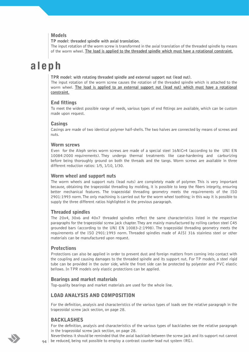
Rotation directionsThe rotation directions and the respective linear movements are showed in the drawings below. In standard
conditions,UNIMEC supplies screw jacks equipped with right-handed worm screw, to which the movements
illustrated in drawings 1 and 2 correspond. Upon request it is possible to have a left-handed worm screw, to
which the movements illustrated in drawings 3 and 4 correspond. The combinations between threaded
spindles and left-handed or right-handed worm screw, lead to the four combinations listed in the table below.
Emergency operationIn case of black-out, in order to be able to operate the single screw jacks or the complete structures by means
of a crank, a free end on the screw jack worm screw or on the transmission is to be foreseen. In case of self-
braking motors or worm screw motor reducers, the brake must firstly be released and then it is necessary to
disassemble those components from the transmission as the reducer could also be irreversible.
It is advisable to equip the emergency operation mechanism with a safety device to cut the electric circuit.
Worm screw DX DX SX SX
Threaded spindle DX SX DX SX
Direct motorization on the worm screw Possible Possible Impossible Impossible
Handling 1-2 3-4 3-4 1-2
Size 420 630 740
fast ratio [daN] 700 1000 1800
normal ratio [daN] 700 1000 1800
slow ratio [daN] 700 1000 1800
1 2 3 4
96

LUBRICATION
Inner lubrication Thanks to particular solutions during the molding process, a film of pure polymer is formed on the moldedcomponents surfaces, which has high sliding properties.This factor, in synergy with light services, enables theAleph series to work in absence of lubricant. Anyway the presence of a lubricant layer on the threaded spindlecan extend the screw jacks life; for the lubricants choice make reference to what has been indicated in thecorrespondent paragraph in the screw jacks section (page 32).It should be reminded that the Aleph series does not foresee any oil plug.
INSTALLATION AND MAINTENANCE
InstallationThe screw jack must be installed in such a manner as not to create lateral loads on the threaded spindle. Greatcare must be taken to ensure that the threaded spindle is orthogonal to the mounting plane, and that the loadand threaded spindle are on the same axis. Employing multiple screw jacks to handle the same load (see themounting schemes section) requires further verifications: it is critical that the load support points, (the endfittings for TP models and the lead nuts for TPR models), be perfectly aligned in order that the load can beuniformly distributed; otherwise the misaligned screw jacks would act as brake or counter-load. Wheneverseveral jacks have to be connected by means of transmission shafts, it is recommended that they be perfectlyaligned in order to avoid overloading on the worm screws.It is advisable to use joints capable of absorbing alignment errors but having at the same time a rigid torsionnecessary to keep the synchronization of the transmission.The assembly or disassembly of the joints or pulleysof worm screw must be carried out by means of tie rods or extractors, using, if necessary, the threaded hole ontop of the worm screw; striking or hammering could damage the inner bearings.For heat-shrinking joints or pulleys, we recommend a temperature between 80-100 °C. Installationsenvironments with dust, water, vapors, etc. require precautions systems to protect the threaded spindle.This canbe done by using elastic protections or rigid protections.The above protections are also used in order to avoid any accidental human contact with the moving devices.
Start-upAll Aleph screw jacks undergo a careful quality examination before being delivered to the client, and are
dynamically tested load-free. When starting-up a machine where screw jacks are installed, it is critical tocheck for the lubrication of the threaded spindles (whether foreseen and if possible) and for the absence offoreign material. During the calibration of the electrical end-of-stroke systems, the inertia of the movingmasses should be considered, which for vertical loads will be lower in ascent and greater in descent. It isadvisable to start the machine with the minimum possible load and to make sure all components are workingproperly, before assuming regular operation. Especially at start-up, it is critical to follow the instructionsgiven in the manual: continuous or hazardous testing maneuvers could lead to an abnormal overheating andcause irreparable damages.One only temperature peak is enough to cause premature wear or breakdown of the aleph screw jack.
Routine maintenanceScrew jacks must be periodically inspected, depending on the use and working environment.
StorageThe screw jacks must be protected from deposits of dust and foreign matter during storage. Particularattention must be paid to saline or corrosive atmospheres. We recommend to store Aleph screw jacks in aclosed place, in order to avoid an excessive water absorption of the polymer.We also recommend to:
- Lubricate and protect the threaded spindle, the worm screw and the non varnished components- Support the threaded spindle in case of horizontal storage.
WarrantyThe warranty is valid only when the instructions contained in our manual are carefully followed.
ORDERING CODEFollow the indications on page 35.
97 ha
nd
lin
g,in
sta
lla
tion
an
d m
ain
ten
an
ce

TP MODEL
1 Casing (half-shell)
4 Worm wheel
5 Worm screw
5.1 Motor worm screw
right-handed
6 Threaded spindle
8 Worm screw bearing
8.1 Motor worm screw bearing
9 Worm wheel bearing
15 Rigid protection
16 Key
18 End fitting elastic
fastening pin
20 Elastic protection
21 End fitting
22 Motor flange
23 Screw
24 Bolt
25 Nut
21
18
6
20
9
4
9
16
16
16
5
5.1
8.1
22
23
815
24
1
8
1
25
98
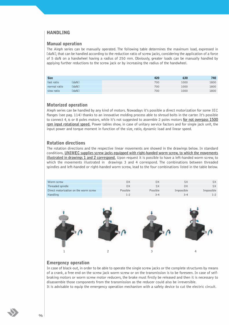
TPR MODEL
Casing (half-shell)
Worm wheel
Worm screw
Motor worm screw
Threaded spindle
Lead nut
Worm screw bearing
Motor worm screw bearing
Worm wheel bearing
Key
Worm wheel elastic fastening pin
Elastic protection
Motor flange
Screw
Bolt
Nut
1
4
5
5.1
6
7
8
8.1
9
16
18.1
20
22
23
24
25
22
23
7
20
24
1
9
4
18.1
18.1
9
8
16
16
16
5
5.1
8
8.1
1
25
6
99 exp
lod
ed
vie
ws
an
d s
pa
re p
art
s

Taille
Portée admissibile [daN]
Tige trapézoïdale : diamètre x pas [mm]
Rapport de réduction théorique rapide
normal
lent
Rapport de réduction réel rapide
normal
lent
Course tige pour un tour de la roue hélicoïdale [mm]
Course tige pour un tour de la vis sans fin [mm] rapide
normal
lent
Rendement [%] rapide
normal
lent
Température d'exercice [°C]
Poids vis trapézoïdale pour 100 mm [kg]
Poids vérin (sans vis) [kg]
DIMENSIONING OF THE SCREW JACKFor a correct dimensioning of the screw jack it is necessary to observe the following steps:
DESCRIPTIVE TABLES
Calculation of the unit load (B)
negative
negative
negative
negative
positive
positive
positive
positive
negative
positive
positive
negative
Verification at the torque (G)
Verification at the radial loads (H)
end
Definition of the application data (A)
Verification at the lateral load (F)
Verification at the buckling load (E)
Verification at the equivalent power (D)
Verification at the equivalent load (C)
Change the size or
mounting scheme
SIZE
Admissible load [daN]
Trapezoidal spindle: diameter per pitch [mm]
Theoretical reduction ratio fast
normal
slow
Real reduction ratio fast
normal
slow
Spindle stroke for a turn of the worm wheel [mm]
Spindle stroke for a turn of the worm screw [mm] fast
normal
slow
Running efficiency [%] fast
normal
slow
Operation temperature [°C]
Weight of the trapezoidal screw for 100 mm [kg]
Weight of the screw jack (screw not included) [kg]
420 630 740
700 1000 1800
20x4 30x6 40x7
1/5 1/5 1/5
1/10 1/10 1/10
1/30 1/30 1/30
4/19 4/19 6/30
2/21 3/29 3/30
1/30 1/30 1/30
4 6 7
0,8 1,2 1,4
0,4 0,6 0,7
0,13 0,2 0,23
31 30 28
28 26 25
20 18 18
10/60 (for different conditions contact our Technical office)
0,22 0,5 0,9
1 2,7 3100

A - THE APPLICATION DATAFor a right dimensioning of the screw jacks it is necessary to identity the application data:
LOAD [daN] = the load is identified with the force applied to the translating device of a screw jack. Normally
the dimensioning is calculated considering the maximum applicable load (worst case). It is important to
consider the load as a vector, which is defined by a modulus, a direction and a sense, the modulus quantifies
the force, the direction orients spatially and gives indications on the eccentricity or on possible lateral loads,
the sense identifies the traction or compression load.
TRANSLATION SPEED [mm/min] = the translation speed is the load handling speed. From this speed it is
possible to calculate the rotation speed of the rotating devices and the necessary handling power. Wear
phenomena and the life of the screw jack proportionally depend on the value of the translation speed.
Therefore, it is advisable to limit the translation speed as much as possible. NEVER exceed 1500 rpm for the
Aleph series.
STROKE [mm] = it is the linear measure used to handle a load. It may not always coincide with the total
length of the threaded spindle.
AMBIENT VARIABLES = these values identify the environment and the operating conditions of the screw
jack. Among them: temperature, oxidizing and corrosive factors, working and non-working periods, vibrations,
maintenance and cleaning, lubrication quality and quantity etc.
MOUNTING SCHEMES = There are several ways of handling a load by means of screw jacks.The schemes
on pages 90-91 will show some examples. Choosing a mounting scheme will condition the choice for the size
and the power which is necessary for the application.
B - THE UNIT LOAD AND THE DESCRIPTIVE TABLESAccording to the n number of screw jacks contained in the mounting scheme, it is possible to calculate each
screw jack’s load by dividing the total load by n In case the load is not fairly distributed in all screw jacks,
it is recommended to consider the transmission having the heaviest load, by virtue of a dimensioning based
on the worst case. According to that value, reading the descriptive tables, it is possible to effect a preliminary
selection choosing between the sizes which present an admissible load value higher than the unit load.
C - THE EQUIVALENT LOADAll the values listed in the catalogue refer to standard use conditions, i.e. a temperature of 20 °C, 50%
humidity, foreseen lifetime 10000 cycles, manual handling without shocks and working percentage 10%. For
different application conditions, the equivalent load should be calculated: it is the load which would be
applied in standard conditions in order to have the same thermal exchange and wear effects, which the real
load achieves in the real conditions of use.
It is therefore advisable to calculate the equivalent load according to the following formula
Ce = C•ft•fa•fs•fu•fd•fv
101 dim
en
sion
ing
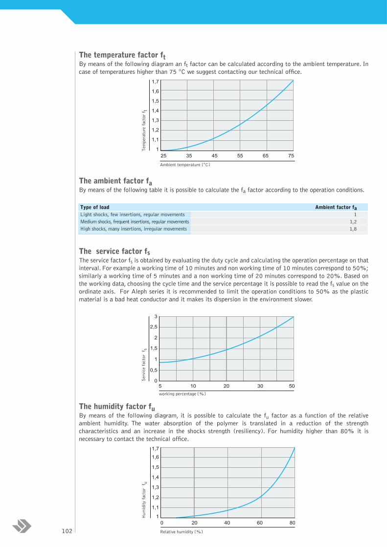
The temperature factor ftBy means of the following diagram an ft factor can be calculated according to the ambient temperature. In
case of temperatures higher than 75 °C we suggest contacting our technical office.
The ambient factor faBy means of the following table it is possible to calculate the fa factor according to the operation conditions.
The service factor fsThe service factor fs is obtained by evaluating the duty cycle and calculating the operation percentage on that
interval. For example a working time of 10 minutes and non working time of 10 minutes correspond to 50%;
similarly a working time of 5 minutes and a non working time of 20 minutes correspond to 20%. Based on
the working data, choosing the cycle time and the service percentage it is possible to read the fs value on the
ordinate axis. For Aleph series it is recommended to limit the operation conditions to 50% as the plastic
material is a bad heat conductor and it makes its dispersion in the environment slower.
The humidity factor fuBy means of the following diagram, it is possible to calculate the fu factor as a function of the relative
ambient humidity. The water absorption of the polymer is translated in a reduction of the strength
characteristics and an increase in the shocks strength (resiliency). For humidity higher than 80% it is
necessary to contact the technical office.
1
1,1
1,2
1,3
1,4
1,5
1,6
1,7
200 40 60 80
Relative humidity [%]
Humidity factor fu
0
0,5
1
1,5
2
2,5
3
5 10 20 30 50
Service factor fs
working percentage [%]
Type of load Ambient factor fa
Light shocks, few insertions, regular movements 1
Medium shocks, frequent insertions, regular movements 1,2
High shocks, many insertions, irregular movements 1,8
1
1,1
1,2
1,3
1,4
1,5
1,6
1,7
25 35 45 55 65 75
Ambient temperature [°C]
Temperature factor f t
102

The duration factor fdBy means of the following diagram it is possible to calculate the fd factor as a function of the expected
operating life expressed in cycle numbers.
The speed factor fvBy means of the following diagram it is possible to calculate the fv factor as a function of the input rotation
speed on the worm screw expressed in [rpm]. Due to the polymer’s physical characteristics, the 1500 rpm
speed should never be exceeded, otherwise this could cause very serious wear phenomena.
With the aid of the descriptive tables it is possible to check whether the previously chosen size is able to
support an admissible dynamic load equal to the equivalent load. If not it is necessary to effect a second
selection.
D - THE POWER TABLES AND THE EQUIVALENT POWERIn the following pages it is possible to find the power tables. Choosing the tables referring to the size selected
in paragraph C and putting the equivalent load values as well as the translation speed values in the table, it
is possible to obtain the equivalent power Pe value. If the crossing values fall into the colored area, this means
that the application conditions could cause negative phenomena such as overheating and strong wear. It is
therefore necessary to reduce the translation speed or to increase the size.
The equivalent power is not the power requested by the single screw jack, unless the six correction factors
ft, fa, fs, fu, fd, and fv have a unit value.
1
1,5
2
2,5
3
3,5
4
0 200 400 600 800 1000 1200 1400 1600
input rotation speed [rpm]
Speed factor f v
1
1,1
1,2
1,3
1,4
1,5
10.000 100.000 1.000.000
expected operating life [number of cycles]
Duration factor f d
103 dim
en
sion
ing
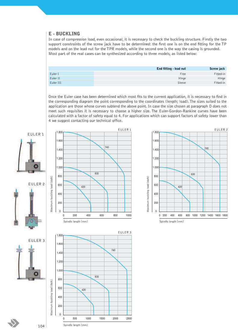
E - BUCKLINGIn case of compression load, even occasional, it is necessary to check the buckling structure. Firstly the two
support constraints of the screw jack have to be determined: the first one is on the end fitting for the TP
models and on the lead nut for the TPR models, while the second one is the way the casing is grounded.
Most part of the real cases can be synthesized according to three models, as listed below:
Once the Euler case has been determined which most fits to the current application, it is necessary to find in
the corresponding diagram the point corresponding to the coordinates (length; load).The sizes suited to the
application are those whose curves subtend the above point. In case the size chosen at paragraph D does not
meet such requisites it is necessary to choose a higher size. The Euler-Gordon-Rankine curves have been
calculated with a factor of safety equal to 4. For applications which can support factors of safety lower than
4 we suggest contacting our technical office.
End fitting - lead nut Screw jack
Euler I Free Fitted-in
Euler II Hinge Hinge
Euler III Sleeve Fitted-in
420
630
740
0
1.800
1.600
1.400
1.200
1.000
800
600
400
200
0 200 400 600 800 1000
Spindle length [mm] Spindle length [mm]
Maximum buckling load [daN]
420
740
630
0
1.800
1.600
1.400
1.200
1.000
800
600
400
200
0 500 1000 1500 2000 2500
Spindle length [mm]
Maximum buckling load [daN]
420
630
740
0
1.800
1.600
1.400
1.200
1.000
800
600
400
200
0 200 400 600 800 1000 1200 1400 1600 1800
Maximum buckling load [daN]
EULER 1
EULER 3
EULER 2
EULER 3
EULER 1
EULER 2
104
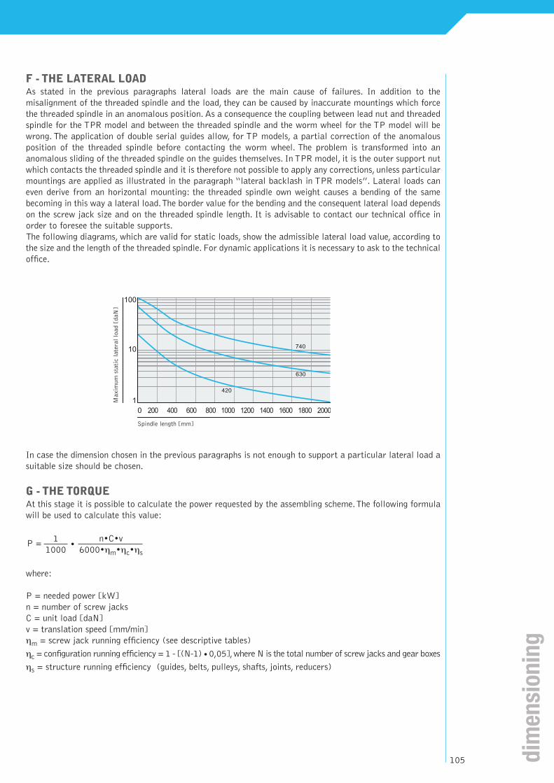
F - THE LATERAL LOADAs stated in the previous paragraphs lateral loads are the main cause of failures. In addition to the
misalignment of the threaded spindle and the load, they can be caused by inaccurate mountings which force
the threaded spindle in an anomalous position. As a consequence the coupling between lead nut and threaded
spindle for the TPR model and between the threaded spindle and the worm wheel for the TP model will be
wrong. The application of double serial guides allow, for TP models, a partial correction of the anomalous
position of the threaded spindle before contacting the worm wheel. The problem is transformed into an
anomalous sliding of the threaded spindle on the guides themselves. In TPR model, it is the outer support nut
which contacts the threaded spindle and it is therefore not possible to apply any corrections, unless particular
mountings are applied as illustrated in the paragraph “lateral backlash in TPR models”. Lateral loads can
even derive from an horizontal mounting: the threaded spindle own weight causes a bending of the same
becoming in this way a lateral load.The border value for the bending and the consequent lateral load depends
on the screw jack size and on the threaded spindle length. It is advisable to contact our technical office in
order to foresee the suitable supports.
The following diagrams, which are valid for static loads, show the admissible lateral load value, according to
the size and the length of the threaded spindle. For dynamic applications it is necessary to ask to the technical
office.
In case the dimension chosen in the previous paragraphs is not enough to support a particular lateral load a
suitable size should be chosen.
G - THE TORQUEAt this stage it is possible to calculate the power requested by the assembling scheme.The following formula
will be used to calculate this value:
where:
P = needed power [kW]
n = number of screw jacks
C = unit load [daN]
v = translation speed [mm/min]
ηm = screw jack running efficiency (see descriptive tables)
ηc = configuration running efficiency = 1 - [(N-1) •0,05],where N is the total number of screw jacks and gear boxes
ηs = structure running efficiency (guides, belts, pulleys, shafts, joints, reducers)
1 n•C•v
1000 6000•ηm•ηc•ηsP = •
Maximum static lateral load [daN]
420
630
740
1
10
100
0 200018001600140012001000800600400200
Spindle length [mm]
105 dim
en
sion
ing
In order to complete the calculation of the requested power, it is necessary to calculate the torque which
should be transmitted by the drive shaft:
where:
Mtm = is the torque on the drive shaft [daNm]
P = is the motor power [kW]
ωm = is the angular speed of the motor [rpm]
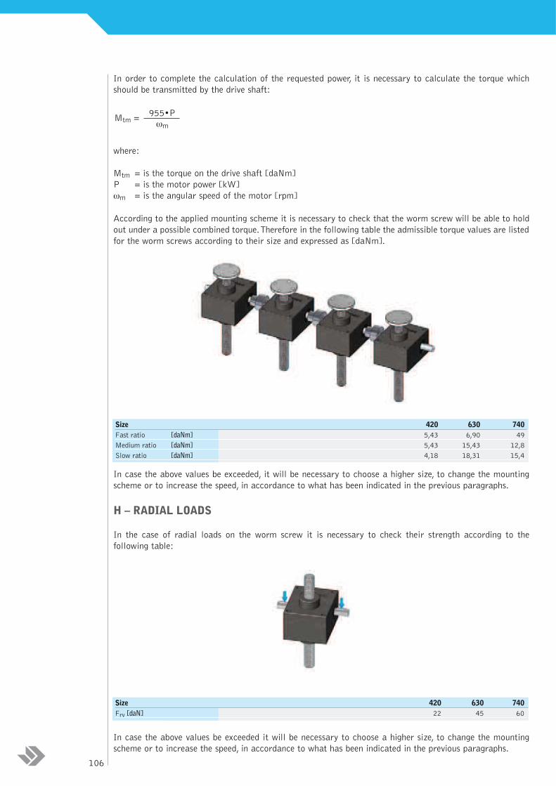
According to the applied mounting scheme it is necessary to check that the worm screw will be able to hold
out under a possible combined torque.Therefore in the following table the admissible torque values are listed
for the worm screws according to their size and expressed as [daNm].
In case the above values be exceeded, it will be necessary to choose a higher size, to change the mounting
scheme or to increase the speed, in accordance to what has been indicated in the previous paragraphs.
H – RADIAL LOADS
In the case of radial loads on the worm screw it is necessary to check their strength according to the
following table:
In case the above values be exceeded it will be necessary to choose a higher size, to change the mounting
scheme or to increase the speed, in accordance to what has been indicated in the previous paragraphs.
Size 420 630 740
Frv [daN] 22 45 60
Size 420 630 740
Fast ratio [daNm] 5,43 6,90 49
Medium ratio [daNm] 5,43 15,43 12,8
Slow ratio [daNm] 4,18 18,31 15,4
955•Pωm
Mtm =
106
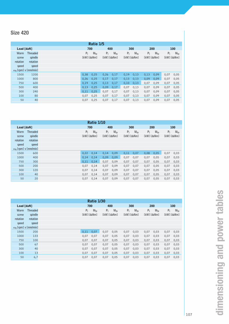
Size 420
Ratio 1/5
Load [daN] 700 400 300 200 100
Ratio 1/10
Load [daN] 700 400 300 200 100
Ratio 1/30
Load [daN] 700 400 300 200 100
Worm Threaded Pi Mtv Pi Mtv Pi Mtv Pi Mtv Pi Mtv
screw spindle [kW] [daNm] [kW] [daNm] [kW] [daNm] [kW] [daNm] [kW] [daNm]
rotation rotation
speed speed
ωv [rpm] v [mm/min]
1500 1200 0,38 0,25 0,26 0,17 0,19 0,13 0,13 0,09 0,07 0,05
1000 800 0,26 0,25 0,17 0,17 0,13 0,13 0,09 0,09 0,07 0,05
750 600 0,19 0,25 0,13 0,17 0,10 0,13 0,07 0,09 0,07 0,05
500 400 0,13 0,25 0,09 0,17 0,07 0,13 0,07 0,09 0,07 0,05
300 240 0,11 0,25 0,07 0,17 0,07 0,13 0,07 0,09 0,07 0,05
100 80 0,07 0,25 0,07 0,17 0,07 0,13 0,07 0,09 0,07 0,05
50 40 0,07 0,25 0,07 0,17 0,07 0,13 0,07 0,09 0,07 0,05
Worm Threaded Pi Mtv Pi Mtv Pi Mtv Pi Mtv Pi Mtv
screw spindle [kW] [daNm] [kW] [daNm] [kW] [daNm] [kW] [daNm] [kW] [daNm]
rotation rotation
speed speed
ωv [rpm] v [mm/min]
1500 600 0,22 0,14 0,14 0,09 0,11 0,07 0,08 0,05 0,07 0,03
1000 400 0,14 0,14 0,09 0,09 0,07 0,07 0,07 0,05 0,07 0,03
750 300 0,11 0,14 0,07 0,09 0,07 0,07 0,07 0,05 0,07 0,03
500 200 0,07 0,14 0,07 0,09 0,07 0,07 0,07 0,05 0,07 0,03
300 120 0,07 0,14 0,07 0,09 0,07 0,07 0,07 0,05 0,07 0,03
100 40 0,07 0,14 0,07 0,09 0,07 0,07 0,07 0,05 0,07 0,03
50 20 0,07 0,14 0,07 0,09 0,07 0,07 0,07 0,05 0,07 0,03
Worm Threaded Pi Mtv Pi Mtv Pi Mtv Pi Mtv Pi Mtv
screw spindle [kW] [daNm] [kW] [daNm] [kW] [daNm] [kW] [daNm] [kW] [daNm]
rotation rotation
speed speed
ωv [rpm] v [mm/min]
1500 200 0,11 0,07 0,07 0,05 0,07 0,03 0,07 0,03 0,07 0,03
1000 133 0,07 0,07 0,07 0,05 0,07 0,03 0,07 0,03 0,07 0,03
750 100 0,07 0,07 0,07 0,05 0,07 0,03 0,07 0,03 0,07 0,03
500 67 0,07 0,07 0,07 0,05 0,07 0,03 0,07 0,03 0,07 0,03
300 40 0,07 0,07 0,07 0,05 0,07 0,03 0,07 0,03 0,07 0,03
100 13 0,07 0,07 0,07 0,05 0,07 0,03 0,07 0,03 0,07 0,03
50 6,7 0,07 0,07 0,07 0,05 0,07 0,03 0,07 0,03 0,07 0,03
107 dim
en
sion
ing
an
d p
ow
er
tab
les

Size 630
Ratio 1/5
Load [daN] 1000 750 500 250
Worm Threaded Pi Mtv Pi Mtv Pi Mtv Pi Mtv
screw spindle [kW] [daNm] [kW] [daNm] [kW] [daNm] [kW] [daNm]
rotation rotation
speed speed
ωv [rpm] v [mm/min]
1500 1800 0,98 0,64 0,74 0,48 0,49 0,32 0,25 0,17
1000 1200 0,65 0,64 0,49 0,48 0,33 0,32 0,17 0,17
750 900 0,49 0,64 0,37 0,48 0,25 0,32 0,13 0,17
500 600 0,33 0,64 0,25 0,48 0,17 0,32 0,10 0,17
300 360 0,20 0,64 0,15 0,48 0,10 0,32 0,10 0,17
100 120 0,10 0,64 0,10 0,48 0,10 0,32 0,10 0,17
50 60 0,10 0,64 0,10 0,48 0,10 0,32 0,10 0,17
Ratio 1/10
Load [daN] 1000 750 500 250
Worm Threaded Pi Mtv Pi Mtv Pi Mtv Pi Mtv
screw spindle [kW] [daNm] [kW] [daNm] [kW] [daNm] [kW] [daNm]
rotation rotation
speed speed
ωv [rpm] v [mm/min]
1500 900 0,57 0,37 0,43 0,28 0,29 0,19 0,16 0,10
1000 600 0,38 0,37 0,29 0,28 0,20 0,19 0,10 0,10
750 450 0,29 0,37 0,22 0,28 0,15 0,19 0,10 0,10
500 300 0,19 0,37 0,15 0,28 0,10 0,19 0,10 0,10
300 180 0,12 0,37 0,10 0,28 0,10 0,19 0,10 0,10
100 60 0,10 0,37 0,10 0,28 0,10 0,19 0,10 0,10
50 30 0,10 0,37 0,10 0,28 0,10 0,19 0,10 0,10
Ratio 1/30
Load [daN] 1000 750 500 250
Worm Threaded Pi Mtv Pi Mtv Pi Mtv Pi Mtv
screw spindle [kW] [daNm] [kW] [daNm] [kW] [daNm] [kW] [daNm]
rotation rotation
speed speed
ωv [rpm] v [mm/min]
1500 300 0,28 0,18 0,22 0,14 0,14 0,09 0,07 0,05
1000 200 0,19 0,18 0,14 0,14 0,10 0,09 0,07 0,05
750 150 0,14 0,18 0,11 0,14 0,07 0,09 0,07 0,05
500 100 0,10 0,18 0,07 0,14 0,07 0,09 0,07 0,05
300 60 0,07 0,18 0,07 0,14 0,07 0,09 0,07 0,05
100 20 0,07 0,18 0,07 0,14 0,07 0,09 0,07 0,05
50 10 0,07 0,18 0,07 0,14 0,07 0,09 0,07 0,05
108

Size 740
Ratio 1/5
Load [daN] 1800 1500 1000 500
Worm Threaded Pi Mtv Pi Mtv Pi Mtv Pi Mtv
screw spindle [kW] [daNm] [kW] [daNm] [kW] [daNm] [kW] [daNm]
rotation rotation
speed speed
ωv [rpm] v [mm/min]
1500 2100 2,45 1,59 1,84 1,20 1,23 0,80 0,62 0,40
1000 1400 1,64 1,59 1,23 1,20 0,82 0,80 0,41 0,40
750 1050 1,23 1,59 0,92 1,20 0,62 0,80 0,31 0,40
500 700 0,82 1,59 0,62 1,20 0,41 0,80 0,21 0,40
300 420 0,49 1,59 0,37 1,20 0,25 0,80 0,13 0,40
100 140 0,17 1,59 0,13 1,20 0,10 0,80 0,10 0,40
50 70 0,10 1,59 0,10 1,20 0,10 0,80 0,10 0,40
Ratio 1/10
Load [daN] 1800 1500 1000 500
Worm Threaded Pi Mtv Pi Mtv Pi Mtv Pi Mtv
screw spindle [kW] [daNm] [kW] [daNm] [kW] [daNm] [kW] [daNm]
rotation rotation
speed speed
ωv [rpm] v [mm/min]
1500 1050 1,40 0,90 1,05 0,67 0,70 0,45 0,35 0,23
1000 700 0,92 0,90 0,69 0,67 0,46 0,45 0,23 0,23
750 525 0,70 0,90 0,52 0,67 0,35 0,45 0,18 0,23
500 350 0,46 0,90 0,35 0,67 0,23 0,45 0,12 0,23
300 210 0,28 0,90 0,21 0,67 0,14 0,45 0,10 0,23
100 70 0,10 0,90 0,10 0,67 0,10 0,45 0,10 0,23
50 35 0,10 0,90 0,10 0,67 0,10 0,45 0,10 0,23
Ratio 1/30
Load [daN] 1800 1500 1000 500
Worm Threaded Pi Mtv Pi Mtv Pi Mtv Pi Mtv
screw spindle [kW] [daNm] [kW] [daNm] [kW] [daNm] [kW] [daNm]
rotation rotation
speed speed
ωv [rpm] v [mm/min]
1500 350 0,63 0,41 0,48 0,31 0,32 0,21 0,17 0,11
1000 233 0,42 0,41 0,32 0,31 0,21 0,21 0,11 0,11
750 175 0,32 0,41 0,24 0,31 0,16 0,21 0,08 0,11
500 117 0,21 0,41 0,16 0,31 0,11 0,21 0,07 0,11
300 70 0,13 0,41 0,10 0,31 0,07 0,21 0,07 0,11
100 23 0,07 0,41 0,07 0,31 0,07 0,21 0,07 0,11
50 11,7 0,07 0,41 0,07 0,31 0,07 0,21 0,07 0,11
109 pow
er
tab
les
D model
Series constructionmodels
B model
S model
110
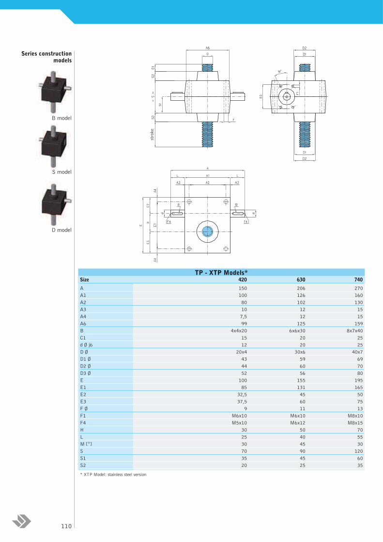
TP - XTP Models*Size 420 630 740
A 150 206 270
A1 100 126 160
A2 80 102 130
A3 10 12 15
A4 7,5 12 15
A6 99 125 159
B 4x4x20 6x6x30 8x7x40
C1 15 20 25
d Ø j6 12 20 25
D Ø 20x4 30x6 40x7
D1 Ø 43 59 69
D2 Ø 44 60 70
D3 Ø 52 56 80
E 100 155 195
E1 85 131 165
E2 32,5 45 50
E3 37,5 60 75
F Ø 9 11 13
F1 M6x10 M6x10 M8x10
F4 M5x10 M6x12 M8x15
H 30 50 70
L 25 40 55
M [°] 30 45 30
S 70 90 120
S1 35 45 60
S2 20 25 35
* XTP Model: stainless steel version
stroke
stroke
protrusion
total length
Series constructionmodels
D model
S model
B model
111
TP
-TP
R m
od
els
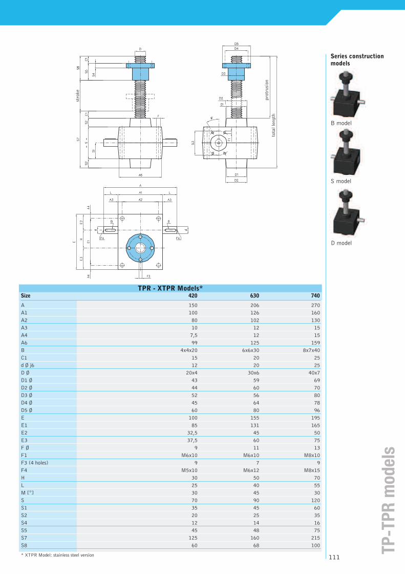
TPR - XTPR Models*Size 420 630 740
A 150 206 270
A1 100 126 160
A2 80 102 130
A3 10 12 15
A4 7,5 12 15
A6 99 125 159
B 4x4x20 6x6x30 8x7x40
C1 15 20 25
d Ø j6 12 20 25
D Ø 20x4 30x6 40x7
D1 Ø 43 59 69
D2 Ø 44 60 70
D3 Ø 52 56 80
D4 Ø 45 64 78
D5 Ø 60 80 96
E 100 155 195
E1 85 131 165
E2 32,5 45 50
E3 37,5 60 75
F Ø 9 11 13
F1 M6x10 M6x10 M8x10
F3 (4 holes) 9 7 9
F4 M5x10 M6x12 M8x15
H 30 50 70
L 25 40 55
M [°] 30 45 30
S 70 90 120
S1 35 45 60
S2 20 25 35
S4 12 14 16
S5 45 48 75
S7 125 160 215
S8 60 68 100
* XTPR Model: stainless steel version

End fittings - X*
Size 420 630 740
C1 15 20 25
D Ø 15 20 30
D 1 Ø 79 89 109
D2 Ø 60 67 85
D3 Ø 39 46 60
D4 Ø 14x2 20x2,5 30x3,5
D5 Ø 38 48 68
D6 Ø 20x1,5 30x2 39x3
D7 k6 15 20 25
D12 20x4 30x6 40x7
F1 (4 holes) 11 12 13
L1 21 23 30
L2 8 10 15
L3 20 30 30
L4 25 30 45
L6 35 45 55
L7 40 50 70
L8 10 10 10
L9 75 95 125
L10 20 25 30
L11 70 80 100
* X Model: stainless steel version
TM TL TPN
TLN
TC
TF TLR TMR
112

End fittings - X*
Size 420 630 740
C1 15 20 25
CH 19 30 41**
D5 Ø 38 48 68
D8 Ø 20 34 48
D9 Ø 32 50 70**
D11 Ø 22 34 50**
E 24 40 55
E1 24 40 55
F Ø H9 10 14 22
F2 Ø H9 20 25 35
F3 Ø 12 20 30
F4 Ø 12 20 30**
G 12 20 30
H 48 80 110
H1 14 25 38
H2 18 30 38
H3 24 40 54
H4 50 77 110**
H5 16 25 35**
H6 6,5 10 15**
H7 17 27 36**
L 50 60 80
L5 40 50 70
L6 35 45 55
S 14 20 30
S1 25 30 40
S2 12 18 25**
S3 16 25 37**
α [º] 13 14 17**
* X Model: stainless steel version** Not available in stainless steel
TOR TO
TFC TOC
113 en
d fi
ttin
gs
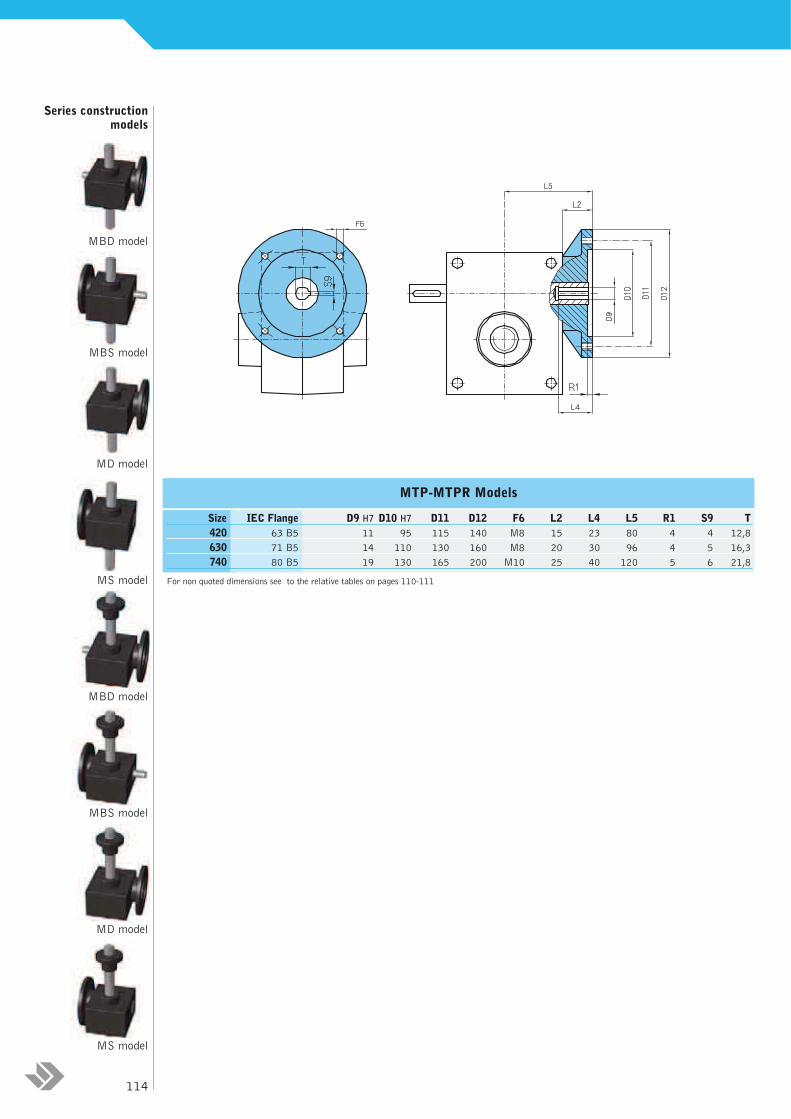
MTP-MTPR Models
Size IEC Flange D9 H7 D10 H7 D11 D12 F6 L2 L4 L5 R1 S9 T
420 63 B5 11 95 115 140 M8 15 23 80 4 4 12,8
630 71 B5 14 110 130 160 M8 20 30 96 4 5 16,3
740 80 B5 19 130 165 200 M10 25 40 120 5 6 21,8
For non quoted dimensions see to the relative tables on pages 110-111
Series constructionmodels
MD model
MS model
MBD model
MBS model
MD model
MS model
MBS model
MBD model
114

PR rigid protectionThe application of a rigid protection in the back side of the screw jack is the ideal solution in order to prevent
dust and foreign matters from coming into contact with the coupling and causing damages to the threaded spindle.
The PR protection can only be applied to TP models. The overall dimensions are shown in the following table.
Incompatibility: TPR models.
BU Anti withdrawing bush If there’s the necessity the spindle, in case of extra-stroke, not to withdraw from the jack body, it’s possible
assembling a steel withdrawing bush.The BU has a trapezoidal thread, able to sustain the load in extra-stroke
case.The BU can apply only in TP models. In case of PRF stroke control, the BU has the function of end-of-stroke
too. It’s important underline that one only extra-stroke attempt (and the consequent impact between BU and
the carter) can hopeless damage the transmission.
The overall dimensions are shown in the table below.
Incompatibility: TPR models – PRA
Anti withdrawing bush BU - XBU Models *
Size 420 630 740
L 25 25 25
M Ø 38 48 58
* XBU Model: stainless steel versionFor non quoted dimensions see to the relative tables on pages 110-111
PR rigid protection - XPR Models*
Size 420 630 740
D8 Ø 48 65 74
D13 Ø 46 63 72
S3 50 60 75
For non quoted dimensions see to the relative tables on pages 110-111* XPR Model: stainless steel version
S3+stroke
stroke
115 access
oir
es
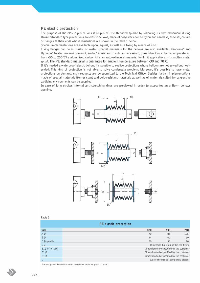
PE elastic protectionThe purpose of the elastic protections is to protect the threaded spindle by following its own movement during
stroke.Standard type protections are elastic bellows,made of polyester covered nylon and can have,as serial, collars
or flanges at their ends whose dimensions are shown in the table 1 below.
Special implementations are available upon request, as well as a fixing by means of iron.
Fixing flanges can be in plastic or metal. Special materials for the bellows are also available: Neoprene® and
Hypalon® (water sea environment), Kevlar® (resistant to cuts and abrasion), glass fiber (for extreme temperatures,
from -50 to 250°C) e aluminized carbon (it’s an auto-extinguish material for limit applications with molten metal
spits). The PE standard material is guarantee for ambient temperature between -30 and 70°C.
If it’s needed a waterproof elastic bellow, it’s possible to realize protections whose bellows are not sewed but heat-
sealed. This kind of protection is not able to solve condensate problem. Moreover, it’s possible to have metal
protections on demand; such requests are be submitted to the Technical Office. Besides further implementations
made of special materials fire-resistant and cold-resistant materials as well as of materials suited for aggressive
oxidizing environments can be supplied.
In case of long strokes internal anti-stretching rings are previewed in order to guarantee an uniform bellows
opening.
Table 1
PE elastic protection
Size 420 630 740
A Ø 70 85 105
B Ø 44 60 69
D Ø spindle 20 30 40
C Ø Dimension function of the end fitting
E1Ø (n°of holes) Dimension to be specified by the costumer
F1 Ø Dimension to be specified by the costumer
G1 Ø Dimension to be specified by the costumer
L 1/8 of the stroke (completely closed)
For non quoted dimensions see to the relative tables on pages 110-111
116
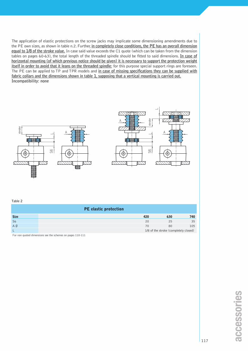
The application of elastic protections on the screw jacks may implicate some dimensioning amendments due to
the PE own sizes, as shown in table n.2. Further, in completely close conditions, the PE has an overall dimension
equal to 1/8 of the stroke value. In case said value exceeds the C1 quote (which can be taken from the dimension
tables on pages 60-63), the total length of the threaded spindle should be fitted to said dimensions. In case of
horizontal mounting (of which previous notice should be given) it is necessary to support the protection weight
itself in order to avoid that it leans on the threaded spindle; for this purpose special support rings are foreseen.
The PE can be applied to TP and TPR models and in case of missing specifications they can be supplied with
fabric collars and the dimensions shown in table 1, supposing that a vertical mounting is carried out.
Incompatibility: none
Table 2
PE elastic protection
Size 420 630 740
S6 20 25 35
A Ø 70 80 105
L 1/8 of the stroke (completely closed)
For non quoted dimensions see the schemes on pages 110-111
stroke
stroke
117 access
ori
es

PRF stroke controlIn order to meet the requirement of an electric stroke control it is possible to apply to a rigid protection
suitable supports for end-of-stroke. In the standard version these supports are of two types and they are
placed at the ends of the stroke in one of the four positions shown below.They are carried out in such a way
as to allow a small adjustment. In case more than one end-of-stroke are needed, it is possible to provide
intermediate supports or a continuous support for the requested length. In order to enable the end-of-stroke
to operate, a steel bushing is mounted on the threaded spindle. More bushings can be mounted upon request.
The PRF can only be applied to TP models and in case of missing specifications it will be supplied with the
supports mounted according to position 1. Sensor are supplied only on demand. The overall dimensions are
shown in the table below. Moreover it’s possible assembling magnetic sensors on the protection, avoiding to
mill it.The end-of-stroke signal is given by a magnet attached on the bottom of the spindle.
Incompatibility: TPR – PRO models - CU
PRF stroke control - XPRF Models*Size 420 630 740
A 55 60 70
B 35 50 50
C 45 45 45
D 18 18 18
E 38 47 51
F Ø 46 63 72
G Ø 48 65 74
L 25 25 25
M Ø 38 48 58
N 40 40 40
P 5 5 5
For non quoted dimensions see to the schemes on pages 110-111* XPRF Model: stainless steel version
DA and FD models (pages 86-87) can suit Aleph series.
stroke
118

The stainless steel seriesFor application where a permanent resistance to oxidizing is necessary, it is possible to supply the following
components in stainless steel: spindles and terminals. The worm, if it’s necessary and on demand, can be
realized in stainless steel to or can undergo a Niploy treatment. The stainless steel series can be applied in
the sea environment without any oxidizing problems.
For further informations see pages 226-229.
NORMS
ATEX directive (94/9/CE)The 94/9/CE directive is better known as the “ATEX directive”. All UNIMEC’s products may be classified
as “components” according to the definition quoted in art.1 par.3 c), and therefore they do not require an
ATEX mark. A conformity declaration in accordance to what stated in art.8 par.3 can be supplied upon end
user’s request, subject to the filling up of a questionnaire with the indication of the working parameters.
Machinery directive (98/37/CE)The 98/37/CE directive is better known as the “Machinery directive”. UNIMEC’s components are included
in the products categories which do not need to affix the CE mark, as they are “intended to be incorporated
or assembled with other machinery” (art.4 par.2). Upon end user’s request a manufacturer declaration can
be supplied in accordance to what is foreseen at Annex II, point B.The new machine directory (06/42/CE)
will be acknowledged by 29/12/2009. UNIMEC guarantees that every new duty in mechanical transmission
will be followed by such date.
Food law regulationsPolymer which is the constitutive material of the Aleph series is suited to the food industry applications.Upon
customer’s request it is possible to provide certifications according to the following norms:
NSF 51
BS 6920
90/128/CE DIRECTIVE
MIL-STD 810
UNI EN ISO 9001:2000 normUNIMEC has always considered the company’s quality system management as a very important
subject. That is why, since the year 1996, UNIMEC is able to show its UNI EN ISO 9001
certification, at the beginning in accordance to the 1994 norms and now meeting the
requirements of the version published in the year 2000. 13 years of company’s quality, certified
by UKAS the world’s most accredited certification body, take shape into an organization which
is efficient at each stage of the working process. In date 31/10/2008 the new version of this norm was
published. UNIMEC will evaluate every news reported in this revision.
119 access
ori
es
an
d n
orm
s