alkali-silica reactivity field identification handbook
DESCRIPTION
Federal Highway Administration handbook provides fundamental information, guidance and photos to identify and manage ASR on various cocrete structures in the field.TRANSCRIPT

ALKALI-SILICA REACTIVITY FIELD IDENTIFICATION HANDBOOK


Technical Report Documentation Page
1. Report No. FHWA-HIF-12-022
2. Government Accession No. 3. Recipient’s Catalog No.
4. Title and Subtitle Alkali-Silica Reactivity Field Identification Handbook
5. Report Date December 2011
6. Performing Organization Code
7. Author(s) Thomas, M.D.A., Fournier, B., Folliard, K.J., Resendez, Y.A.
8. Performing Organization Report No.
9. Performing Organization Name and Address The Transtec Group, Inc. 6111 Balcones Drive Austin, TX 78731
10. Work Unit No.
11. Contract or Grant No. DTFH61-06-D-00035
12. Sponsoring Agency Name and Address Office of Pavement Technology Federal Highway Administration 1200 New Jersey Avenue, DE Washington, DC 20590
13. Type of Report and Period Covered Final Report December 2011
14. Sponsoring Agency Code
15. Supplementary Notes Contracting Officer’s Technical Representative (COTR): Gina Ahlstrom, HIPT-20
16. Abstract Two types of alkali-aggregate reaction (AAR) are currently recognized depending on the nature of the reactive mineral; these are alkali-silica reaction (ASR) and alkali-carbonate reaction (ACR). Both types of reaction can result in expansion and cracking of concrete elements, leading to a reduction in the service life of concrete structures. This handbook serves as an illustrated guide to assist users in detecting and distinguishing ASR in the field from other types of damages.
17. Key Words Alkali-silica reactivity, alkali-aggregate reaction, reactive aggregates, concrete durability, field identification, concrete
18. Distribution Statement No restrictions. This document is available to the public through the National Technical Information Service, Springfield, VA 22161.
9. Security Classif. (of this report)
20. Security Classif. (of this page)
21. No of Pages 22. Price


SI* (MODERN METRIC) CONVERSION FACTORS APPROXIMATE CONVERSIONS TO SI UNITS
Symbol When You Know Multiply By To Find Symbol
in ftyd mi
in2
ft2
yd2
ac mi2
fl oz gal ft3
yd3
oz lb T
oF
fc fl
lbf lbf/in2
LENGTH inches 25.4 millimeters feet 0.305 meters yards 0.914 meters
miles 1.61 kilometers AREA
square inches 645.2 square millimeters square feet 0.093 square meters square yard 0.836 square meters acres 0.405 hectares square miles 2.59 square kilometers
VOLUME fluid ounces 29.57 milliliters gallons 3.785 liters cubic feet 0.028 cubic meters cubic yards 0.765 cubic meters
NOTE: volumes greater than 1000 L shall be shown in m3
MASS ounces 28.35 grams pounds 0.454 kilograms short tons (2000 lb) 0.907 megagrams (or "metric ton")
TEMPERATURE (exact degrees) Fahrenheit 5 (F-32)/9 Celsius
or (F-32)/1.8 ILLUMINATION
foot-candles 10.76 lux foot-Lamberts 3.426 candela/m2
FORCE and PRESSURE or STRESS poundforce 4.45 newtons poundforce per square inch 6.89 kilopascals
mm m m km
mm2
m 2
m2
ha km2
mL L m3
m 3
g kg Mg (or "t")
oC
lx cd/m2
N kPa
APPROXIMATE CONVERSIONS FROM SI UNITS Symbol When You Know Multiply By To Find Symbol
mmmmkm
mm2
m2
m2
hakm2
mL Lm3
m3
g kg Mg (or "t")
oC
lx cd/m2
N kPa
LENGTH millimeters 0.039 inches
meters 3.28 feet meters 1.09 yards
kilometers 0.621 miles AREA
square millimeters 0.0016 square inches square meters 10.764 square feet square meters 1.195 square yards
hectares 2.47 acres square kilometers 0.386 square miles
VOLUME milliliters 0.034 fluid ounces liters 0.264 gallons cubic meters 35.314 cubic feet cubic meters 1.307 cubic yards
MASS grams 0.035 ounces kilograms 2.202 pounds megagrams (or "metric ton") 1.103 short tons (2000 lb)
TEMPERATURE (exact degrees) Celsius 1.8C+32 Fahrenheit
ILLUMINATION lux 0.0929 foot-candles candela/m2 0.2919 foot-Lamberts
FORCE and PRESSURE or STRESS newtons 0.225 poundforce kilopascals 0.145 poundforce per square inch
in ft yd mi
in2
ft2
yd2
ac mi2
fl oz gal ft3
yd3
oz lb T
oF
fc fl
lbf lbf/in2
*SI is the symbol for th e International System of Units. Appropriate rounding should be made to comply with Section 4 of ASTM E380. (Revised March 2003)


TABLE OF CONTENTS
FOREWORD…………………………………………………………………..1
INTRODUCTION.............................................................................................. 3
REQUIREMENTS FOR ASR .......................................................................... 5
FIELD SYMPTOMS OF ASR .......................................................................... 7
CRACKING ......................................................................................................... 7 EXPANSION CAUSING MOVEMENTS AND DEFORMATIONS ................................. 9 LOCALIZED CRUSHING OF CONCRETE ............................................................... 9 EXTRUSION OF JOINT-SEALING MATERIAL ...................................................... 11 SURFACE POP-OUTS ......................................................................................... 11 SURFACE DISCOLORATION AND GEL EXUDATIONS .......................................... 11
EFFECT OF EXPOSURE CONDITIONS.................................................... 13
MOISTURE ....................................................................................................... 13 TEMPERATURE ................................................................................................. 13
ASR IN COMBINATION WITH OTHER DETERIORATION PROCESSES .................................................................................................... 15
ASR AND STEEL CORROSION .......................................................................... 15 ASR AND FREEZE-THAW DETERIORATION....................................................... 15 ASR AND DELAYED ETTRINGITE FORMATION ................................................. 15
NON-ASR-RELATED DISTRESS................................................................. 17
MANAGING STRUCTURES AFFECTED BY ASR................................... 19
REFERENCES................................................................................................. 21
APPENDIX A: ASR IN BRIDGE STRUCTURES....................................... 23
APPENDIX B: ASR IN CONCRETE PAVEMENTS................................... 49
APPENDIX C: ASR IN OTHER TRANSPORTATION STRUCTURES................................................................................................. 61


FOREWORD
This field identification handbook provides guidance in identifying alkali-silica reactivity (ASR) in concrete field structures, such as bridges and pavements. The handbook also provides fundamental information about ASR, including the requirements for ASR to take place and the chemical reaction that leads to the formation of ASR gel. Furthermore, this handbook provides images to assist the reader in identifying ASR in the field under several scenarios, such as the effect of moisture on ASR-affected structures, ASR in combination with other concrete distresses, and non-ASR related distresses. A section is also dedicated to assist the reader in managing ASR-affected structures.
Moreover, the appendices in this handbook have been categorized to illustrate ASR in bridge structures, concrete pavements, and other transportation structures.
This document is meant to serve as a guide for assessing potential ASR structures in the field. As such, laboratory testing, such as petrographic analysis, should be conducted in order to confirm the presence of ASR in hardened concrete.
1

INTRODUCTION
Two types of alkali-aggregate reaction (AAR) are currently recognized depending on the nature of the reactive mineral; these are:
Alkali-silica reaction (ASR) which involves various types of reactive silica (SiO2) minerals, and
Alkali-carbonate reaction (ACR) which involves certain types of dolomitic rocks (CaMg(CO3)2).
Both types of reaction can result in expansion and cracking of concrete elements, leading to a reduction in the service life of concrete structures. Visual symptoms, such as map-cracking (Figures 1 and 2), on concrete structures affected by either ASR or ACR are generally similar, and a petrographic examination conducted on samples taken from the structure (Figure 3) is usually required to differentiate between the two types of reactions. A reaction product, alkali-silica gel, is typically observed in concrete affected by ASR.
Cases of ACR are limited and confined to a few locations in North America; however, ASR is widespread throughout North America and worldwide. Consequently, the vast majority of illustrations shown in this document are examples of ASR rather than ACR.
In many cases, there may be other destructive forces contributing to the deterioration observed. For example, cyclic freezing and thawing in northern regions can exacerbate the cracking initiated by AAR. In addition, cracks caused by AAR in concrete exposed to deicing salts may provide pathways, allowing access to chloride ions which can promote the corrosion of embedded reinforcement. Consideration should be given to the possibility of these other processes when inspecting a concrete structure for AAR.
2

Figure 1. Map-cracking of a sidewalk caused by ASR.
Figure 2. Map-cracking of a sidewalk caused by ACR.
Figure 3. Alkali-silica gel in petrographic thin section of concrete taken from an ASR-affected structure.
3

REQUIREMENTS FOR ASR
ASR is a chemical reaction between the alkali hydroxides in the pore solution of concrete and certain forms of reactive silica minerals occurring in some aggregates. The reaction product, an alkali-silica gel, is hygroscopic, and will absorb water and swell if the concrete is in a moist environment. The swelling of the gel can, under certain circumstances, lead to expansion and cracking of the concrete. Thus, as shown in Figure 4, there are three requirements for deleterious ASR to occur; these are:
A sufficient concentration of alkali hydroxides in the pore solution of the concrete. The main source of alkalis in concrete is the portland cement, which contains minor amounts of sodium and potassium. In some cases, additional alkalis may be supplied by other components of the concrete (e.g. aggregates, admixtures and supplementary cementing materials) or from external sources (e.g. deicing salts or seawater). A sufficient quantity of reactive minerals in the aggregate. Reactive minerals include opal, cristobalite, tridymite, volcanic glass and various forms of microcrystalline, cryptocrystalline and strained quartz. A sufficient supply of moisture. ASR ceases below a relative humidity of 80 percent, but increases in intensity as the relative humidity within the concrete increases from 80 percent to 100 percent.
The sequence of ASR is illustrated in Figure 5.
Damage due to ASR can be avoided in new construction by either avoiding reactive aggregates or by controlling the availability of alkali in the concrete. Two ways to control the availability of alkali include the use of low-alkali cement and the use of suitable supplementary cementing materials.
In existing ASR-affected structures, the rate of reaction, and hence, the rate of damage accumulation, can be reduced by lowering the internal relative humidity where possible.
4

Figure 4. Requirements for ASR.Silica (SiO2)
Alkali (Na, K) Water Figure 5. Sequence of ASR.
Reaction between the alkali hydroxides (Na, K & OH) from the cement and unstable silica, SiO2, in some types of aggregate.
5
SiO2
Na+
K+
OH
OH
Na+
K+
OH
OH
Gel The reaction produces an alkali-silica gel.
The gel absorbs water from the surrounding paste …
… and expands.
The internal expansion eventually leads to cracking of the surrounding concrete.

FIELD SYMPTOMS OF ASR
Common visual symptoms of ASR generally consist of: Cracking Expansion causing deformation, relative movement, and displacement Localized crushing of concrete Extrusion of joint material Surface pop-outs Surface discoloration and gel exudations
Brief descriptions of the symptoms are given in this section. Multiple photographs of these features in various transportation structures are given in the appendices of this handbook.
Cracking The classic symptom of ASR is map cracking (also called pattern cracking or alligator cracking), which takes the form of randomly-oriented cracks on the surface of concrete elements that are relatively free (unrestrained) to move in all directions. An example is shown in Figure 6. In some cases, discoloration occurs around the cracks, often due to gel exudation in the vicinity of the cracks. In many cases, expansion is restrained in one or more directions due to internal confinement from conventional reinforcement or prestressing, or by external forces from abutments or adjacent structures. In such cases, more expansion occurs in the direction of least confinement, and the cracks become oriented in the same direction as the confining stresses. For example, with concrete pavements, the expansion is restrained in the longitudinal direction; thus, a greater amount of expansion occurs in the transverse direction. Hence, cracks will show a preferred alignment in the longitudinal direction (see Figure 7). In the case of reinforced concrete columns, cracks tend to be aligned vertically due to the restraint imposed by the primary reinforcement and the dead load (see Figure 8). For prestressed bridge girders, the cracks will usually be aligned horizontally due to the confinement imposed by the prestressing tendons parallel to the axis of the beam (see Figure 9).
6

7
Figure 6. Map cracking (a.k.a. pattern cracking or alligator cracking) in a concrete wall.
Figure 7. Preferred alignment of cracks in an ASR-affected concrete pavement.
Figure 8. Preferred alignment of cracks in an ASR-affected concrete column.

Expansion causing deformation, relative movement, and displacement The extent of ASR often varies between or within the various members or components of an affected concrete structure, thus causing distresses such as:
relative movement or misalignment of adjacent concrete members deflection collateral damage to adjacent structures
Figure 10 shows an example of movement.
Localized crushing of concrete Expansion leading to the closure of joints can lead to localized crushing of concrete if incompressible material becomes lodged in the joint prior to the joint closing completely. The presence of the incompressible material can lead to local high stress concentrations. For an example, see Figure 11.
8

Figure 9. Preferred alignment of cracks on an ASR-affected pre-stressed concrete girder.
Figure 10. Differential movement of parapet wall on a bridge.
Figure 11. Expansion with associated spalling of concrete in abutting Jersey barrier sections affected by ASR.
9

Extrusion of joint-sealing material
Expansion of adjacent sections results in closure of the joint. If joint-sealing material is present, it may be “squeezed out” of the joint as it closes, as shown in Figure 12.
Surface pop-outs
Alkali-reactive aggregates undergoing expansion near the concrete surface may induce the detachment of a conical portion of the mortar overlying the aggregate and leaving the reactive aggregate exposed in the bottom of the resulting conical recess. Such features are termed popouts, and more frequently result from freeze-thaw action on frost-susceptible rock types, such as certain varieties of chert and argillaceous, clayey or porous particles. See Figure 13.
Surface discoloration and gel exudations
Cracks caused by ASR are often bordered by a broad “brownish” zone, giving the appearance of permanent dampness (Figure 14). Surface gel exudations are also a common feature of ASR. The exudation may be alkali-silica gel or lime (or both) leaching from the cracked concrete.
10

Figure 12. Extrusion of joint-sealing material between adjacent sections of concrete pavement.
Figure 13. Map-cracking accompanied by numerous pop-outs caused by shaly limestone particles.
Figure 14. Surface discoloration and exudation associated with cracks.
11

EFFECT OF EXPOSURE CONDITIONS
Moisture
The extent of ASR in a concrete structure will vary depending on a number of factors, including the exposure conditions. Concrete that is exposed directly to moisture is likely to exhibit more severe symptoms of ASR than concrete that is less exposed to moisture. As an example, Figure 15 shows a bent cap where only part of the cap has direct exposure to moisture and consequently shows signs of ASR. The part of the bent cap that is not directly exposed to moisture does not show signs of ASR, even though they are both part of the same concrete specimen.
The moisture conditions can also affect the visibility of cracks. For example, fine cracks may not be readily visible on a concrete element viewed on a dry day, but may be easily seen shortly after a rainfall as the surface dries (see Figure 16). The reason for this effect is that the cracks retain the moisture longer, and this enhances the contrast between the crack and the concrete surface.
Temperature
The rate of reaction is highly dependent on the composition of the concrete and the exposure condition (moisture availability and temperature). Typically, symptoms are manifested 5 to 10 years after construction. However, concrete containing moderately-reactive aggregates and exposed to colder northern environments may not show symptoms of ASR until it reaches an age of 15 years or more. Conversely, concrete containing highly reactive aggregate and exposed to hot, humid climates may exhibit cracking due to ASR after less than 2 years, as in Figure 17.
12

Figure 15. Bent cap showing signs of ASR only where the element has direct access to moisture.
Figure 16. ASR cracks enhanced as the concrete starts to dry following rainfall.
Figure 17. ASR-affected pre-stressed concrete box girder. Cracking became visible after two years.
13

ASR IN COMBINATION WITH OTHER DETERIORATION PROCESSES
ASR can occur simultaneously with other deterioration processes or may render the concrete more vulnerable to these processes after ASR damage has occurred.
ASR and steel corrosion
Cracking due to ASR provides pathways for chloride ions from deicing salts or seawater to rapidly penetrate the concrete cover and initiate corrosion of embedded reinforcement. One instance of corroded steel is shown in Figure 18.
ASR and freeze-thaw deterioration
ASR can reduce the resistance of concrete to cyclic freezing and thawing, even if the concrete is adequately air-entrained. If cracks induced by ASR become saturated the freezing water will propagate and widen the cracks. Horizontal surfaces, such as pavements, are particularly vulnerable to this combination of processes. An example is shown in Figure 19.
ASR and delayed ettringite formation
Delayed ettringite formation (DEF) has often been found in association with ASR. Indeed, ASR can accelerate DEF by reducing the pH of the concrete pore solution, thereby expediting the release of sulfates entrapped by the hydrates during elevated-temperature curing. The released sulfates are then free to form ettringite, and this delayed formation of ettringite increases the expansion and cracking already contributed by ASR. Figure 20 shows effects of ASR and DEF.
14
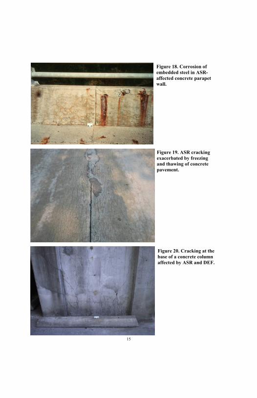
Figure 18. Corrosion of embedded steel in ASR-affected concrete parapet wall.
Figure 19. ASR cracking exacerbated by freezing and thawing of concrete pavement.
Figure 20. Cracking at the base of a concrete column affected by ASR and DEF.
15

NON-ASR-RELATED DISTRESS
There are many causes of cracking and other symptoms of distress in concrete; however, the presence of one or more of the features discussed in the previous sections is not necessarily an indication that ASR is the main process responsible for observed damage.
Volume increase and resulting deformations and misalignments can be caused by sulfate attack, delayed ettringite formation and unsoundness of cement—this will also result in cracking.
Cracking can result from many deterioration processes, including processes that lead to a volume reduction such as thermal, autogenous, plastic and drying shrinkage.
Popouts can be caused by freeze-thaw action in the absence of ASR and exudation and staining in the vicinity of cracks can be caused by moisture movements and leaching of salts (e.g. efflorescence).
All forms of deterioration should be considered when performing a condition survey of a concrete structure.
The extent to which ASR (or ACR) has contributed to the observed damage can only be unequivocally established by taking core samples and performing a laboratory study, including petrographic examination.
Table 1 shows the various symptoms associated with ASR and provides an indication of the probability of ASR occurring based on the presence and extent of the symptoms.
16

Table 1. Classification System for the Condition Survey (modified from CSA, 2000).
Feature Probability of ASR
Low Medium High
Expansion and/ or
displacement of elements
None Some evidence (e.g., closure of joints in pavements, Jersey
barriers, spalls, misalignments between
structural members)
Fair to extensive signs of volume increase leading
to spalling at joints, displacement and/or
misalignment of structural members
Cracking and crack pattern
None Some cracking pattern typical of ASR (e.g.,
map cracking or cracks aligned with major
reinforcement or stress)
Extensive map cracking or cracking aligned with
major stress or reinforcement
Surface discoloration
None Slight surface discoloration associated
with some cracks
Many cracks with dark discoloration and
adjacent zone of light colored concrete
Exudations None White exudations around some cracks;
possibility of colorless, jelly-like exudations
Colorless, jelly-like exudations readily
identifiable as ASR gel associated with several
cracks
17

MANAGING STRUCTURES AFFECTED BY ASR
Performing a condition survey is one part in the process of managing structures affected by ASR. Depending on the structure and the requirements of the owner, there may be no further testing beyond a detailed site investigation. A great many ASR-affected structures remain in service without measures to mitigate the effects of or retard the rate of the reaction. Sudden structural collapse in concrete components affected by ASR is rare. However, if no measures are taken to address the symptoms or abate the reaction, continuing ASR may result in serviceability problems, increased maintenance costs, accelerated deterioration due to other mechanisms, and reduced service life.
As mentioned previously, a confirmed diagnosis as to the presence and extent of ASR requires laboratory testing and petrographic examination of cores. By combining the results of the laboratory investigation and the symptoms from the site investigation, an experienced engineer can determine the likely contribution of ASR to the observed damage. From this diagnosis, it may be possible to immediately recommend measures to mitigate the reaction and its effects. On the other hand, a decision may be made to instrument the structure and monitor future behavior before deciding on a course of action. Alternatively, as discussed above, the decision may be to do nothing more than continue to inspect the structure on a routine basis.
This handbook is only intended to aid the inspector in identifying the symptoms of ASR; Figure 21 shows where a routine inspection or detailed site investigation may fit within the scope of a comprehensive analysis of an ASR-affected structure. Guidelines on the management of affected structures including laboratory testing, field monitoring and mitigation techniques are provided elsewhere (CSA, 2000; FHWA, 2010).
18

Figure 21. General flowchart showing steps in a comprehensive ASR investigation (modified from CSA, 2000).
19

REFERENCES
“Guide to the Evaluation and Management of Concrete Structures Affected by Alkali-Aggregate Reaction,” CSA A864-00, Canadian Standards Association, Toronto, p.108, 2000.
Fournier, B., et al., “Report on the Diagnosis, Prognosis, and Mitigation of Alkali-Silica Reaction (ASR) in Transportation Structures,” Federal Highway Administration, Report. No. FHWA-HIF-09-004, Washington, D.C., 147 p., 2010.
Sutter, L.L., Peterson, K.R., Van Dam, T.J., Smith, K.D., Wade, M.J., “Guidelines for Detection, Analysis, and Treatment of Materials-Related Distress in Concrete Pavements—Volume III: Case Studies Using the Guidelines,” Federal Highway Administration, Report No. FHWA-RD-01-165, Washington, D.C., August 2002.
Van Dam, T.J., Sutter, L.L., Smith, K.D., Wade, M.J., Peterson, K.R., “Guidelines for Detection, Analysis, and Treatment of Materials-Related Distress in Concrete Pavements—Volume I: Final Report,” Federal Highway Administration, Report No. FHWA-RD-01-163, Washington, D.C., August 2002.
Van Dam, T.J., Sutter, L.L., Smith, K.D., Wade, M.J., Peterson, K.R., “Guidelines for Detection, Analysis, and Treatment of Materials-Related Distress in Concrete Pavements—Volume II: Guidelines Description and Use,” Federal Highway Administration, Report No. FHWA-RD-01-164, Washington, D.C., August 2002.
20

COLLECTION OF PHOTOGRAPHS OF ASR-AFFECTED STRUCTURES
Appendix A: ASR in Bridge Structures
Appendix B: ASR in Concrete Pavements
Appendix C: ASR in other Transportation Structures
21

APPENDIX A: ASR IN BRIDGE STRUCTURES
Figure A1. Minor cracking in a concrete bridge deck.
Initially cracks form close to the transverse or longitudinal joints and tend to be orientated perpendicular to the joint.
Figure A2. Moderate cracking in a bridge deck.
As ASR advances, the expansion in the longitudinal direction is restrained and increased expansion occurs in the transverse direction. Consequently, cracks tend to be oriented longitudinally.
22

23

Figure A3. Moderate cracking in bridge abutment and parapet wall.
Note the discoloration (staining) to the surface of the concrete adjacent to the crack. There are also indications that there is some corrosion of the embedded steel as revealed by the rust spots at the surface of the concrete.
Figure A4. Severe cracking of bridge abutment.
Crack widths in excess of ¼ to ½ inch (5 to 10 mm) are evident in some locations.
24

25

Figure A5. Moderate cracking in a precast, prestressed box-girder.
Cracking occurred within a few years of construction. In the end block, adjacent to the abutment, cracking is randomly oriented, but is orientated longitudinally in the main span as the pre-stressing tendons restrain expansion in this direction.
Figure A6. Moderate to severe cracking is a post-tensioned concrete bridge girder.
Note that the main crack appears to follow the line of a draped post-tensioning tendon.
26

27

Figure A7. Severe cracking in the top chord of a reinforced concrete arch bridge.
The cracks follow the shape of the arch and are aligned with the direction of the primary reinforcement.
Figure A8. Cracking on the underside of the arch shown in Figure A7.
Crack widths up to ¼ to ½ inch (5 to 10 mm) were observed.
Note the white exudation associated with cracks in both figures. This was found to be predominantly calcium carbonate with lesser amounts of potassium indicating both lime and alkali leaching from the concrete.
28

29

Figure A9. Severe cracking of reinforced-concrete bridge.
Cracks are orientated in the longitudinal direction of the Y-shaped columns and the horizontal girder. Note there are signs of corrosion (rust spots) on the edge beam.
Figure A10. Very severe cracking of column foundation in bridge shown in Figure A9.
Note that the cracks are orientated randomly in the foundation block as there are lesser amounts of steel and no principle orientation of the steel.
30

31

Figure A11. Misalignment of a parapet wall.
The wall on the left of the photograph sits on the bridge abutment whereas the wall on the right sits on the bridge deck. The displacement between the walls is slightly more than 1 inch (25 mm).
Figure A12. Crushing of concrete on a parapet wall.
Expansion due to ASR has caused the joint between the adjacent wall sections to close. Incompressible material trapped between the two sections caused the buildup of concentrated stresses which led to crushing of the concrete.
32

33

Figure A13. Moderate cracking of a reinforced concrete column.
The wider cracks are aligned vertically due to the restraint imposed by the primary reinforcement and the dead load. Narrow randomly-orientated cracks are also visible.
Figure A14. Moderate to severe cracking on a reinforced concrete column.
As with the Figure A13, the main cracks are aligned vertically. There is some evidence from petrographic examination that delayed ettringite formation may have contributed to the cracking of the concrete in this case.
34

35
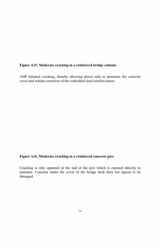
Figure A15. Moderate cracking in a reinforced bridge column.
ASR initiated cracking, thereby allowing deicer salts to penetrate the concrete cover and initiate corrosion of the embedded steel reinforcement.
Figure A16. Moderate cracking in a reinforced concrete pier.
Cracking is only apparent at the end of the pier which is exposed directly to moisture. Concrete under the cover of the bridge deck does not appear to be damaged.
36

37

Figure A17. Minor cracking on an edge beam supporting the bridge railing.
The tight cracks with associated discoloration are typical of the first symptoms of ASR
Figure A18. Severe cracking on an edge beam supporting the bridge railing.
Advanced ASR has led to an extensive network of cracks which has been opened up by freeze-thaw cycles leading to spalling of the concrete.
38

39

Figure A19. Moderate cracking in a wing wall.
The cracking of the wing wall is accompanied by surface discoloration and gel exudation.
Figure A20. Moderate cracking in a wing wall.
Expansion of the concrete has led to the formation of a vertical crack forming along the length of the wall. It is likely that the crack forms between two mats of reinforcement at the back and front face of the wall.
40

41

Figure A21. Severe cracking of a bridge abutment.
The damage is far more advanced in the part of the abutment that is exposed directly to moisture. The part of the abutment sheltered by the bridge deck shows only minor ASR cracking.
Figure A22. Moderate cracking of a massive concrete pier.
The combined effects of ASR and freeze-thaw cycles have led to cracking and surface spalling of the pier. There is also corrosion of the non-structural reinforcement, leading to some spalling of the surface (right of photo).
42

43

Figure A23. Cracking of abutment of bridge undergoing demolition.
ASR cracking is clearly visible in the portion of the abutment that was above grade and exposed to the elements during exposure but much less visible in the portion that was below grade in service.
Figure A24. Enlargement of Figure A23.
This photograph shows the contrast between the appearance of the concrete that was above grade (top) and below grade (bottom) during service. Wetting and drying, combined with freezing and thawing, tends to open up the cracks at the surface and promotes discoloration (staining) around the cracks. Below grade the cracks are finer and less visible; however, the extent of ASR within the concrete is the same above and below grade.
44

45

Figure A25. Cracking on underside of bridge.
This photograph shows moderate ASR cracking on the underside of a bridge. The cracks are aligned longitudinally, reflecting the direction of the primary reinforcement and pre-tensioning.
Figure A26. Cracking on the underside of a bridge deck.
Some salt exudation is observed in association with the cracking (bottom of photo).
46

47

APPENDIX B: ASR IN CONCRETE PAVEMENTS
Figure B1. Minor cracking in a concrete pavement.
The first symptoms of ASR in a concrete pavement are often cracks starting at and running perpendicular to the transverse or longitudinal joints.
Figure B2. Moderate cracking at the corner of pavement slabs.
Map cracking often appears first at the corner of pavement slabs.
48

49

Figure B3. Moderate cracking following the perimeter of pavement slabs.
As ASR advances, the cracks spread around the perimeter of the slabs and there is often little or no cracking in the center of the slab. The reason that the region around the joints is more prone to cracking is because (a) there is often more moisture available at the joints, (b) there is less restraint to expansion close to the joints, and (c) mechanical stresses to vehicular loading are higher at the joints.
Figure B4. Moderate D-cracking of concrete.
This photograph shows durability or D-cracking, and the pattern of the cracks is similar to that shown in Figure B3 above. However, the mechanism is very different as D-cracking results from the expansion of frost-susceptible aggregates.
50

51

Figure B5. Severe cracking of a concrete pavement.
As ASR advances, the whole surface of the concrete pavement exhibits cracking. Usually the cracks become oriented in the longitudinal direction.
Figure B6. Severe map cracking in a concrete pavement.
Although it is usual to observe preferred orientation of cracks in pavements with advanced ASR, map-cracking is often observed. It is possible, in such cases, that drying shrinkage at the pavement surface contributes to the pattern of cracking.
52

53

Figure B7. Concrete pavement slab exhibiting drying shrinkage.
The photograph shows extensive map-cracking of a pavement slab. Petrographic examination of the concrete revealed no evidence of ASR, and the cause of the cracking is assumed to be drying shrinkage; the pavement is located in an arid environment.
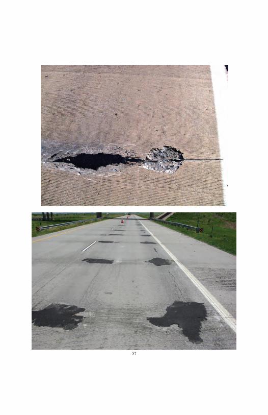
Figure B8. Spall occurring at a joint in a concrete pavement.
As ASR advances, the cracked concrete at the vicinity of the joint may be further distressed by the action of freezing and thawing, and vehicular loading. Eventually, spalling starts to occur at the joint.
54

55

Figure B9. Spall and “repaired” spall at a joint in a concrete pavement.
In many cases, spalling at joints is likely to continue and may require patching.
Figure B10. Severe deterioration of a concrete pavement.
In severe cases, extensive patching can only delay the time until a major repair or replacement is required.
56
57

Figure B11. Severe cracking in a concrete pavement.
Preferred orientation of cracks in the longitudinal direction.
Figure B12. Crushing of concrete and extrusion of joint-sealing material in concrete pavement slabs.
58

59

APPENDIX C: ASR IN OTHER TRANSPORTATION STRUCTURES
Figure C1. Moderate ASR map-cracking in a highway barrier.
The photograph shows map-cracking and surface discoloration of a highway barrier wall.
Figure C2. Moderate ASR oriented cracking in a highway barrier.
In many cases, barrier walls, especially continuous slipformed barriers, will exhibit cracking with preferred orientation (horizontal) due to the restraint to expansion in the direction of the wall.
60

61

Figure C3. Light to moderate cracking at the top of a highway barrier wall and severe deterioration at the base of the wall.
Light to moderate cracking due to ASR is evident in the top portion of the wall. Freeze-thaw action has exacerbated the damage in the bottom portion of the wall, and this has led to severe spalling of the haunches.
Figure C4. Failure of concrete barrier wall.
The photograph shows severe expansion, cracking and spalling of a barrier wall due to ASR. Freeze-thaw has most likely contributed to the deterioration.
62

63

Figure C5. Localized spalling of concrete barrier wall.
The photograph shows moderate map-cracking of the barrier wall resulting from ASR. Freeze-thaw deterioration and spalling has occurred to the haunch just above grade.
Figure C6. Moderate cracking of the foundation for a high-mast light pole.
Cracking orientated vertically due to restraint imposed by reinforcement and embedded bolts for securing pole.
64

65

Figure C7. Moderate cracking of the foundation for a light pole.
Random cracking with excessive exudation resulting from freeze-thaw deterioration (not ASR).
Figure C8. Minor cracking of curb.
Preferred orientation in the horizontal direction due to restraint.
66

67
Figure C9. Moderate cracking in sidewalk due to alkali-silica reaction (ASR).
Figure C10. Severe cracking in sidewalk due to alkali-carbonate reaction (ACR).
68

69


FHWA-HIF-12-022