all fasteners ¼-20 x ½ cap screw and ¼ lock washer...
TRANSCRIPT
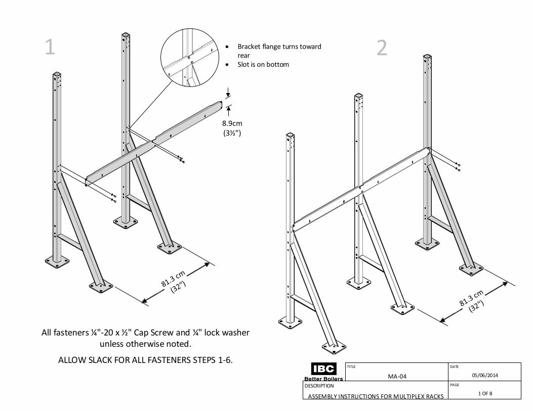
Bracket flange turns toward rear
Slot is on bottom
1 2
All fasteners ¼"-20 x ½" Cap Screw and ¼" lock washer unless otherwise noted.
ALLOW SLACK FOR ALL FASTENERS STEPS 1-6.
8.9cm(3½ )
DATE
05/06/2014
TITLE
MA-04
DESCRIPTION
ASSEMBLY INSTRUCTIONS FOR MULTIPLEX RACKS
PAGE
1 OF 8
4 53
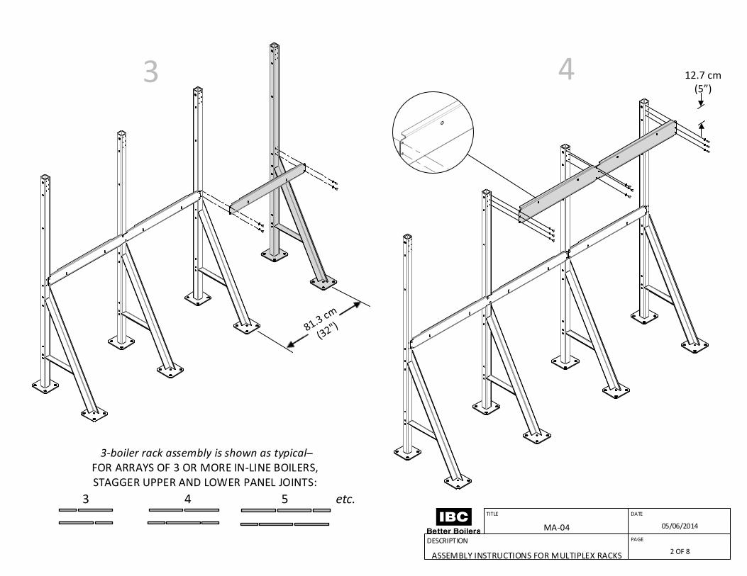
3-boiler rack assembly is shown as typical ̶ FOR ARRAYS OF 3 OR MORE IN-LINE BOILERS, STAGGER UPPER AND LOWER PANEL JOINTS:
etc.
3 12.7 cm(5 )
4
DATE
05/06/2014
TITLE
MA-04
DESCRIPTION
ASSEMBLY INSTRUCTIONS FOR MULTIPLEX RACKS
PAGE
2 OF 8

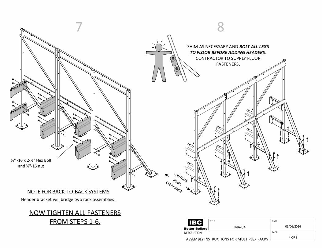
NOTE FOR BACK-TO-BACK SYSTEMS ONLY:Repeat steps 1-6 for opposite side.
Position assemblies in location, noting that header bracket (step 7) will bridge them.
5 6
DATE
05/06/2014
TITLE
MA-04
DESCRIPTION
ASSEMBLY INSTRUCTIONS FOR MULTIPLEX RACKS
PAGE
3 OF 8
7 8
NOW TIGHTEN ALL FASTENERS FROM STEPS 1-6.
⅜" -16 x 2-½" Hex Bolt
and ⅜"-16 nut
NOTE FOR BACK-TO-BACK SYSTEMS
Header bracket will bridge two rack assemblies.
SHIM AS NECESSARY AND BOLT ALL LEGS TO FLOOR BEFORE ADDING HEADERS.
CONTRACTOR TO SUPPLY FLOOR FASTENERS.
DATE
05/06/2014
TITLE
MA-04
DESCRIPTION
ASSEMBLY INSTRUCTIONS FOR MULTIPLEX RACKS
PAGE
4 OF 8

DATE
05/06/2014
TITLE
MA-04
DESCRIPTION
ASSEMBLY INSTRUCTIONS FOR MULTIPLEX RACKS
PAGE
5 OF 8

11
DO NOT TIGHTEN HEADER BOLTS NOR BOTTOM BOILER
BOLTS UNTIL PIPING HAS BEEN FULLY INSTALLED
Brackets are found in the base of each boiler box.
Use centre hole. Bolts are part of racking
package.
12HANG BOILERS ON
BRACKETS
10.1 cm(4")
⅜" -16 x ¾" Cap Screw and ⅜" lock washer
DATE
05/06/2014
TITLE
MA-04
DESCRIPTION
ASSEMBLY INSTRUCTIONS FOR MULTIPLEX RACKS
PAGE
6 OF 8
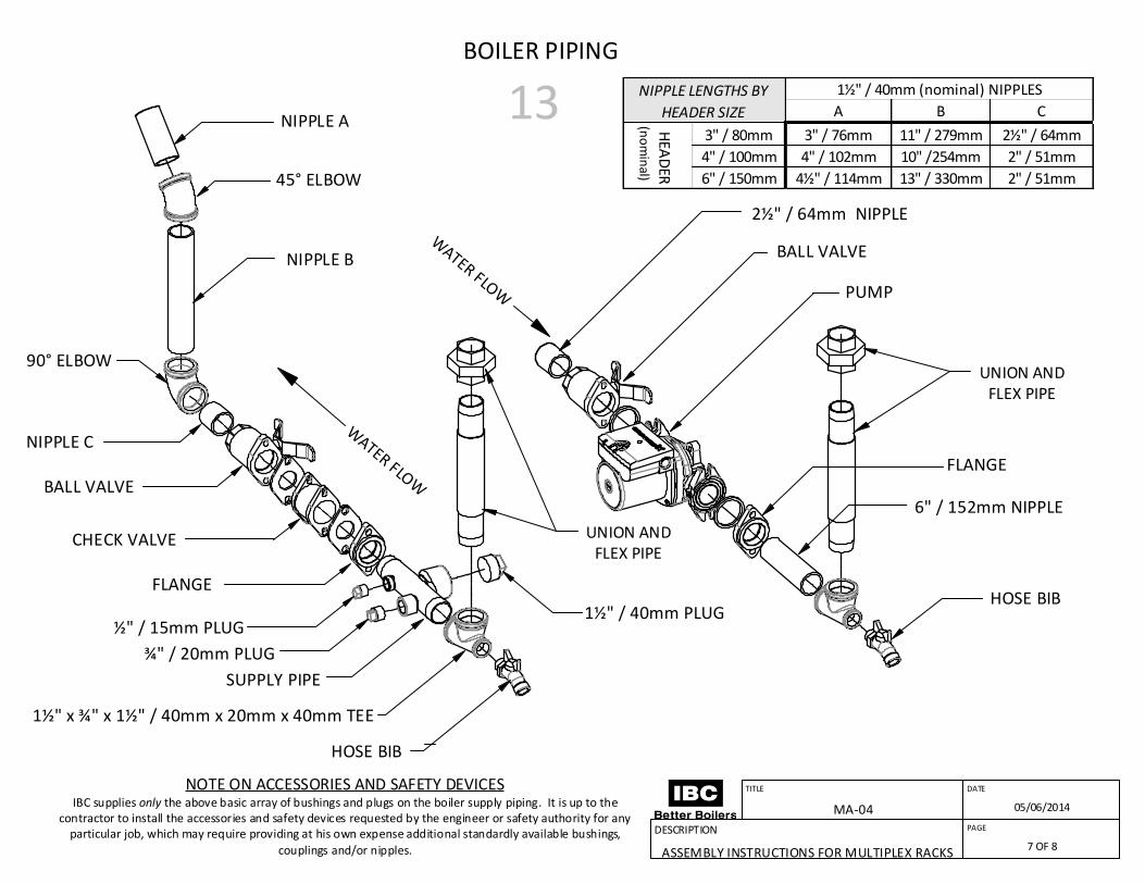
BOILER PIPING
UNION ANDFLEX PIPE
A
B
NIPPLE C
UNION ANDFLEX PIPE
BALL VALVE
CHECK VALVE
FLANGE
½" / 15mm PLUG
¾" / 20mm PLUG
1½" x ¾" x 1½" / 40mm x 20mm x 40mm TEE
1½" / 40mm PLUG
BALL VALVE
PUMP
FLANGE
HOSE BIB
HOSE BIB
SUPPLY PIPE
90° ELBOW
A B C
3" / 80mm 3" / 76mm 11" / 279mm 2½" / 64mm
4" / 100mm 4" / 102mm 10" /254mm 2" / 51mm
6" / 150mm 4½" / 114mm 13" / 330mm 2" / 51mm
1½" / 40mm (nominal) NIPPLES
HEA
DER
(n
om
inal)
NIPPLE LENGTHS BY
HEADER SIZE
2½" / 64mm NIPPLE
DATE
05/06/2014
TITLE
MA-04
DESCRIPTION
ASSEMBLY INSTRUCTIONS FOR MULTIPLEX RACKS
PAGE
7 OF 8
13NIPPLE A
45° ELBOW
NIPPLE B
6" / 152mm NIPPLE
NOTE ON ACCESSORIES AND SAFETY DEVICESIBC supplies only the above basic array of bushings and plugs on the boiler supply piping. It is up to the
contractor to install the accessories and safety devices requested by the engineer or safety authority for any particular job, which may require providing at his own expense additional standardly available bushings,
couplings and/or nipples. couplings and/or nipples.

AFFIX BOILERS TO BOTTOM BRACKET ¼ -20 x ¾" Cap Screw and ¼" Flat Washer with ¼"-20 Nut and ¼" Flat Washer
TIGHTEN HEADER U-BOLTS
14 NOTES
DATE
05/06/2014
TITLE
MA-04
DESCRIPTION
ASSEMBLY INSTRUCTIONS FOR MULTIPLEX RACKS
PAGE
8 OF 8