all models approved for use in california by the cec
TRANSCRIPT
July, 2016
INSTALLATION AND SERVICE MANUALgas-fired weatherproof duct furnaces/make-up air units
power vented models HBP/HCP/HDP/HPP
5-572.9 5H0762330001
THIS MANUAL IS THE PROPERTY OF THE OWNER. PLEASE BE SURE TO LEAVE IT WITH THE OWNER WHEN YOU LEAVE THE JOB.
All models approved for use in California by the CEC.
FOR YOUR SAFETYThe use and storage of gasoline or other flammable vapors and liquids in open containers in the vicinity of this appliance is hazardous.
FOR YOUR SAFETYIF YOU SMELL GAS:1. Open windows.2. Don’t touch electrical switches.3. Extinguish any open flame.4. Immediately call your gas supplier.
Inspection on Arrival1. Inspect unit upon arrival. In case of damage, report it
immediately to transportation company and your local factory sales representative.
2. Check rating plate on unit to verify that power supply meets available electric power at the point of installation.
3. Inspect unit upon arrival for conformance with description of product ordered (including specifications where applicable).
IMPORTANTThe use of this manual is specifically intended for a qualified installation and service agency. A qualified installation and service agency must perform all installation and service of these appliances.
CAUTIONTo prevent premature heat exchanger failure do not locate ANY gas-fired units in areas where chlorinated, halogenated, or acid vapors are present in the atmosphere.
WARNING1. Improper installation, adjustment, alteration,
service or maintenance can cause property damage, injury or death, and could cause exposure to substances which have been determined by various state agencies to cause cancer, birth defects or other reproductive harm. Read the installation, operating and maintenance instructions thoroughly before installing or servicing this equipment.
2. Installing, starting up and servicing heating, ventilation and air conditioning equipment poses significant hazards and requires specialized knowledge of Modine products and training in performing those services. Failure to have any service properly performed by, or making any modification to Modine equipment without the use of, qualified service personnel could result in serious injury to person and property, including death. Therefore, only qualified service personnel should work on any Modine products.
2 5-572.9
SPECIAL PRECAUTIONS / TABLE OF CONTENTS
SPECIAL PRECAUTIONSTHE INSTALLATION AND MAINTENANCE INSTRUCTIONS IN THIS MANUAL MUST BE FOLLOWED TO PROVIDE SAFE, EFFICIENT AND TROUBLE-FREE OPERATION. IN ADDITION, PARTICULAR CARE MUST BE EXERCISED REGARDING THE SPECIAL PRECAUTIONS LISTED BELOW. FAILURE TO PROPERLY ADDRESS THESE CRITICAL AREAS COULD RESULT IN PROPERTY DAMAGE OR LOSS, PERSONAL INJURY, OR DEATH. THESE INSTRUCTIONS ARE SUBJECT TO ANY MORE RESTRICTIVE LOCAL OR NATIONAL CODES.
HAZARD INTENSITY LEVELS1. DANGER: Indicates an imminently hazardous situation
which, if not avoided, WILL result in death or serious injury.2. WARNING: Indicates a potentially hazardous situation
which, if not avoided, COULD result in death or serious injury.3. CAUTION: Indicates a potentially hazardous situation
which, if not avoided, MAY result in minor or moderate injury.4. IMPORTANT: Indicates a situation which, if not avoided,
MAY result in a potential safety concern.
IMPORTANT1. To prevent premature heat exchanger failure, do not locate
ANY gas-fired appliances in areas where corrosive vapors (i.e. chlorinated, halogenated or acid) are present in the atmosphere.
2. To prevent premature heat exchanger failure, the input to the appliance, as indicated on the serial plate, must not exceed the rated input by more than 5%.
3. To prevent premature heat exchanger failure, observe heat exchanger tubes by looking at the heat exchanger through the field installed access openings in connecting ductwork in model HBP or the unit access doors in models HDP, HCP, or HPP. If the bottom of the tubes become red while blower and duct furnace are in operation, check to be sure the blower has been set to the proper rpm for the application. Refer to page 16 for Blower Adjustments.
4. Start-up and adjustment procedures should be performed by a qualified service agency.
5. To check most of the Possible Remedies in the troubleshooting guide listed in Table 52.1, refer to the applicable sections of the manual. DANGER
Appliances must not be installed where they may be exposed to a potentially explosive or flammable atmosphere.
WARNING1. All field gas piping must be pressure/leak tested prior to
operation. Never use an open flame. Use a soap solution or equivalent for testing.
2. Gas pressure to appliance controls must never exceed 14" W.C. (1/2 psi).
3. Disconnect power supply before making wiring connections to prevent electrical shock and equipment damage.
4. All appliances must be wired strictly in accordance with wiring diagram furnished with the appliance. Any wiring different from the wiring diagram could result in a hazard to persons and property.
5. Any original factory wiring that requires replacement must be replaced with wiring material having a temperature rating of at least 105°C.
6. To reduce the opportunity for condensation, the minimum sea level input to the appliance, as indicated on the serial plate, must not be less than 5% below the rated input, or 5% below the minimum rated input of dual rated units.
7. Ensure that the supply voltage to the appliance, as indicated on the serial plate, is not 5% greater than the rated voltage.
8. When servicing or repairing this equipment, use only factory-approved service replacement parts. A complete replacement parts list may be obtained by contacting Modine Manufacturing Company. Refer to the rating plate on the appliance for complete appliance model number, serial number, and company address. Any substitution of parts or controls not approved by the factory will be at the owners risk.
CAUTION1. Appliances are designed for outdoor installation only.
DO NOT LOCATE APPLIANCES INDOORS.2. Purging of air from gas lines should be performed as
described in ANSI Z223.1 - latest edition “National Fuel Gas Code”, or in Canada in CAN/CGA-B149 codes.
3. Ensure that the supply voltage to the appliance, as indicated on the serial plate, is not 5% less than the rated voltage.
4. Do not reuse any mechanical or electrical component which has been wet. Such component must be replaced.
Table of Contents Inspection on Arrival ............................................................ 1Special Precautions ............................................................. 2SI (Metric) Conversion Factors ...........................................3Unit Location .......................................................................3 Combustible Material and Service Clearances .......... 3Sound and Vibration Levels ...............................................4Rigging Instructions ............................................................. 4Curb or Sub-Base Mounting ................................................4Slab Mounting ....................................................................4Duct Installation ................................................................... 5Unit Installation .................................................................... 6 Venting ......................................................................... 6 Gas Connections .........................................................8 Considerations for Elevation ...................................... 10 Electrical Connections ............................................... 11 Evaporative Cooler .................................................... 11 Cooling Coil Specifications and Installation ............... 12Start-Up Procedure ........................................................... 14 Pilot Burner and Main Burner Adjustment ................ 14 Blower Adjustment ....................................................16 Lubrication Recommendations ................................. 16 Damper Linkage Adjustment ....................................16 Control Operating Sequence .................................... 17Options ..............................................................................19General Performance Data ...............................................27Unit Selection ....................................................................29Pressure Drop and Blower Performance Data. ................. 31Blower Sheave Assembly Data .........................................35Dimensions ........................................................................40Weights ..............................................................................49Maintenance ......................................................................50Service & Troubleshooting ................................................52Model Designations ........................................................... 54Start-Up Checklist ............................................................. 56Model Nomenclature ......................................................... 57Commercial Warranty ...........................................Back Page
35-572.9
SI (METRIC) CONVERSION FACTORS / UNIT LOCATION
Location Recommendations1. When locating the furnace, consider general space and heating
requirements and availability of gas and electrical supply.2. Unit must be installed on the positive pressure side of the
circulating blower.3. Be sure the structural support at the unit location site is
adequate to support the weight of the unit and any other required support structure. For proper operation the unit must be installed in a level horizontal position.
4. Do not install units in locations where the flue products can be drawn into the adjacent building openings such as windows, fresh air intakes, etc.
5. Be sure that the minimum clearances to combustible materials and recommended service clearances are maintained. For HBP/HCP/HDP/HPP units, be sure
CAUTIONAppliances are designed for outdoor installation only. DO NOT LOCATE APPLIANCES INDOORS.
IMPORTANTTo prevent premature heat exchanger failure, do not locate ANY gas-fired appliances in areas where corrosive vapors (i.e. chlorinated, halogenated or acid) are present in the atmosphere.
DANGERAppliances must not be installed where they may be exposed to potentially explosive or flammable atmosphere.
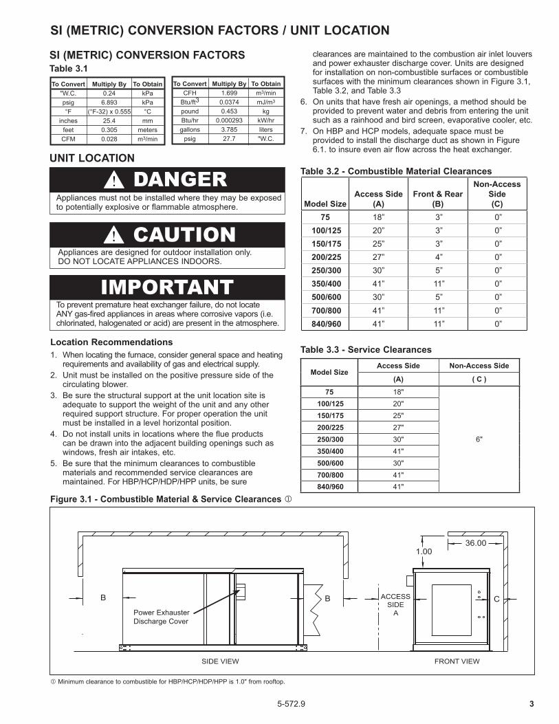
Figure 3.1 - Combustible Material & Service Clearances j
FRONT VIEWSIDE VIEW
1.0036.00
CBB ACCESSSIDE
APower Exhauster Discharge Cover
j Minimum clearance to combustible for HBP/HCP/HDP/HPP is 1.0" from rooftop.
Table 3.1 To Convert Multiply By To Obtain "W.C. 0.24 kPa psig 6.893 kPa °F (°F-32) x 0.555 °C inches 25.4 mm feet 0.305 meters CFM 0.028 m3/min
To Convert Multiply By To Obtain CFH 1.699 m3/min Btu/ft3 0.0374 mJ/m3
pound 0.453 kg Btu/hr 0.000293 kW/hr gallons 3.785 liters psig 27.7 "W.C.
Table 3.3 - Service Clearances
clearances are maintained to the combustion air inlet louvers and power exhauster discharge cover. Units are designed for installation on non-combustible surfaces or combustible surfaces with the minimum clearances shown in Figure 3.1, Table 3.2, and Table 3.3
6. On units that have fresh air openings, a method should be provided to prevent water and debris from entering the unit such as a rainhood and bird screen, evaporative cooler, etc.
7. On HBP and HCP models, adequate space must be provided to install the discharge duct as shown in Figure 6.1. to insure even air flow across the heat exchanger.
Table 3.2 - Combustible Material Clearances
SI (METRIC) CONVERSION FACTORS
UNIT LOCATION
Model SizeAccess Side Non-Access Side
(A) ( C )
75 18"
6"
100/125 20" 150/175 25" 200/225 27" 250/300 30" 350/400 41" 500/600 30" 700/800 41" 840/960 41"
Model SizeAccess Side
(A)Front & Rear
(B)
Non-Access Side (C)
75 18” 3” 0” 100/125 20” 3” 0” 150/175 25” 3” 0” 200/225 27” 4” 0” 250/300 30” 5” 0” 350/400 41” 11” 0” 500/600 30” 5” 0” 700/800 41” 11” 0” 840/960 41” 11” 0”
4 5-572.9
UNIT LOCATION/ROOF CURB INSTALLATION
Sound and Vibration LevelsAll mechanical equipment generates some sound and vibration that may require attenuation. Libraries, private offices, and hospital patient rooms will require more attenuation and in such cases an acoustical consultant may be retained to assist in the application. Locating the equipment away from the critical area is desirable within ducting limitations. Frequently, units can be located above utility areas, corridors, restrooms, and other non-critical areas. Generally, a unit should be located within 15 feet of a primary support beam. Smaller defections mean lesser vibration and noise transmission.
Roof curb must be installed level. If roof is pitched it will be necessary to construct a sub-base on which to install the curb.
Install the unit over roof decking with 2" acoustic fiberglass lining within curb area for sound attenuation. The return air duct should be acoustically lined and should be installed with a flexible connection. If the ceiling space is used as a plenum, the acoustically lined return intake duct should form an inverted tee with five foot minimum legs in each direction.
The discharge duct should be acoustically insulated and should have a flexible connection as illustrated.
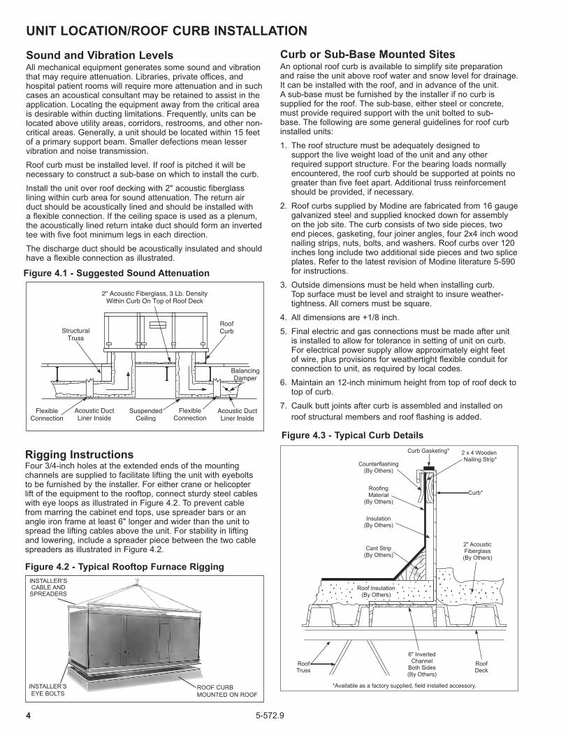
Counterflashing(By Others)
RoofingMaterial
(By Others)
Insulation(By Others)
Cant Strip(By Others)
2 x 4 WoodenNailing Strip*
Curb*
2" AcousticFiberglass(By Others)
RoofDeck
6" InvertedChannel
Both Sides(By Others)
RoofTruss
Curb Gasketing*
*Available as a factory supplied, field installed accessory.
Roof Insulation(By Others)
Figure 4.3 - Typical Curb Details
Curb or Sub-Base Mounted SitesAn optional roof curb is available to simplify site preparation and raise the unit above roof water and snow level for drainage. It can be installed with the roof, and in advance of the unit. A sub-base must be furnished by the installer if no curb is supplied for the roof. The sub-base, either steel or concrete, must provide required support with the unit bolted to sub-base. The following are some general guidelines for roof curb installed units:
1. The roof structure must be adequately designed to support the live weight load of the unit and any other required support structure. For the bearing loads normally encountered, the roof curb should be supported at points no greater than five feet apart. Additional truss reinforcement should be provided, if necessary.
2. Roof curbs supplied by Modine are fabricated from 16 gauge galvanized steel and supplied knocked down for assembly on the job site. The curb consists of two side pieces, two end pieces, gasketing, four joiner angles, four 2x4 inch wood nailing strips, nuts, bolts, and washers. Roof curbs over 120 inches long include two additional side pieces and two splice plates. Refer to the latest revision of Modine literature 5-590 for instructions.
3. Outside dimensions must be held when installing curb. Top surface must be level and straight to insure weather-tightness. All corners must be square.
4. All dimensions are +1/8 inch.
5. Final electric and gas connections must be made after unit is installed to allow for tolerance in setting of unit on curb. For electrical power supply allow approximately eight feet of wire, plus provisions for weathertight flexible conduit for connection to unit, as required by local codes.
6. Maintain an 12-inch minimum height from top of roof deck to top of curb.
7. Caulk butt joints after curb is assembled and installed on roof structural members and roof flashing is added.
Rigging InstructionsFour 3/4-inch holes at the extended ends of the mounting channels are supplied to facilitate lifting the unit with eyebolts to be furnished by the installer. For either crane or helicopter lift of the equipment to the rooftop, connect sturdy steel cables with eye loops as illustrated in Figure 4.2. To prevent cable from marring the cabinet end tops, use spreader bars or an angle iron frame at least 6" longer and wider than the unit to spread the lifting cables above the unit. For stability in lifting and lowering, include a spreader piece between the two cable spreaders as illustrated in Figure 4.2.
Figure 4.1 - Suggested Sound Attenuation
INSTALLER’S CABLE AND SPREADERS
INSTALLER’S EYE BOLTS
ROOF CURB MOUNTED ON ROOF
Figure 4.2 - Typical Rooftop Furnace Rigging
55-572.9
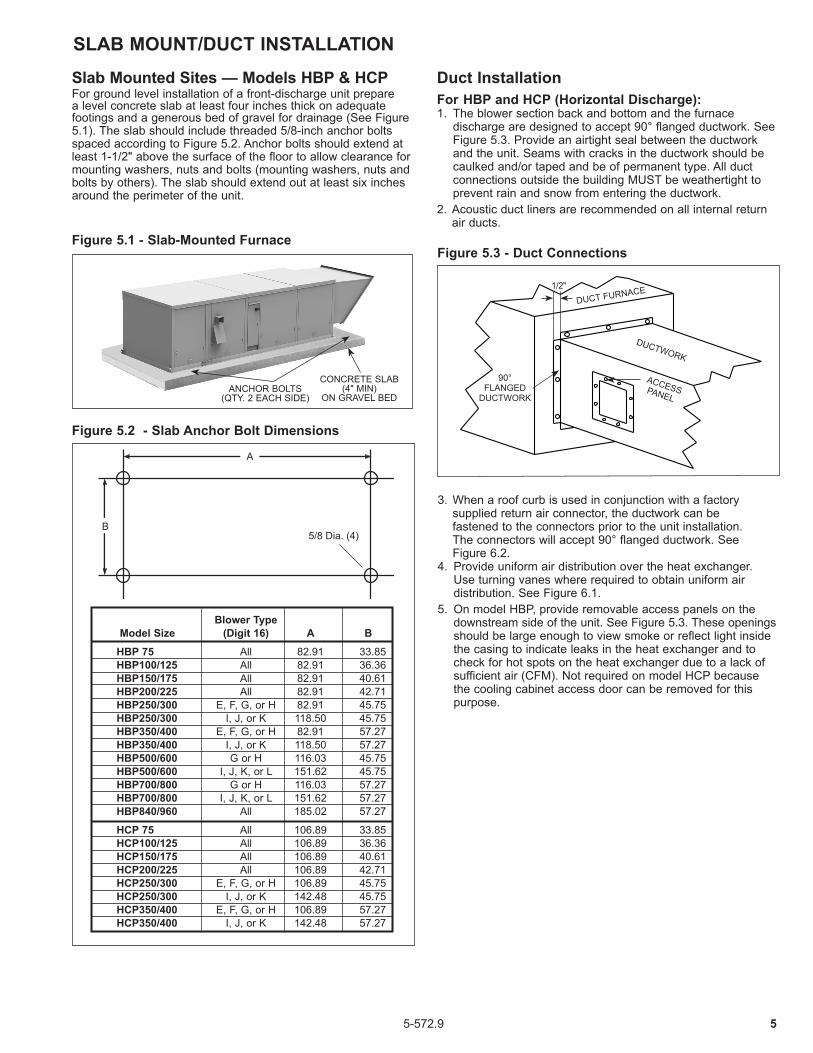
Duct Installation For HBP and HCP (Horizontal Discharge):1. The blower section back and bottom and the furnace
discharge are designed to accept 90° flanged ductwork. See Figure 5.3. Provide an airtight seal between the ductwork and the unit. Seams with cracks in the ductwork should be caulked and/or taped and be of permanent type. All duct connections outside the building MUST be weathertight to prevent rain and snow from entering the ductwork.
2. Acoustic duct liners are recommended on all internal return air ducts.
A
B5/8 Dia. (4)
SLAB MOUNT/DUCT INSTALLATION
ANCHOR BOLTS(QTY. 2 EACH SIDE)
CONCRETE SLAB (4" MIN)
ON GRAVEL BED
DUCT FURNACE
DUCTWORK
ACCESS PANEL
90° FLANGED
DUCTWORK
1/2"
Blower Type Model Size (Digit 16) A B
HBP 75 All 82.91 33.85 HBP100/125 All 82.91 36.36 HBP150/175 All 82.91 40.61 HBP200/225 All 82.91 42.71 HBP250/300 E, F, G, or H 82.91 45.75 HBP250/300 I, J, or K 118.50 45.75 HBP350/400 E, F, G, or H 82.91 57.27 HBP350/400 I, J, or K 118.50 57.27 HBP500/600 G or H 116.03 45.75 HBP500/600 I, J, K, or L 151.62 45.75 HBP700/800 G or H 116.03 57.27 HBP700/800 I, J, K, or L 151.62 57.27 HBP840/960 All 185.02 57.27
HCP 75 All 106.89 33.85 HCP100/125 All 106.89 36.36 HCP150/175 All 106.89 40.61 HCP200/225 All 106.89 42.71 HCP250/300 E, F, G, or H 106.89 45.75 HCP250/300 I, J, or K 142.48 45.75 HCP350/400 E, F, G, or H 106.89 57.27 HCP350/400 I, J, or K 142.48 57.27
Figure 5.3 - Duct ConnectionsFigure 5.1 - Slab-Mounted Furnace
Figure 5.2 - Slab Anchor Bolt Dimensions
3. When a roof curb is used in conjunction with a factory supplied return air connector, the ductwork can be fastened to the connectors prior to the unit installation. The connectors will accept 90° flanged ductwork. See Figure 6.2.
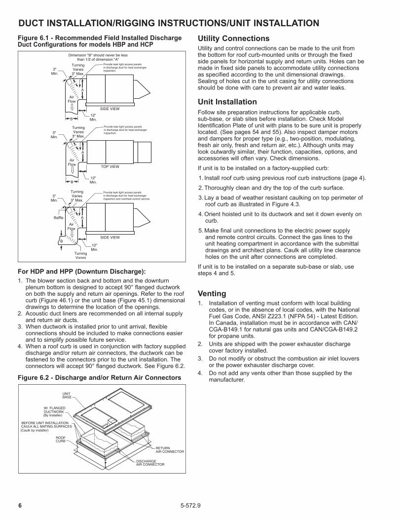
4. Provide uniform air distribution over the heat exchanger. Use turning vanes where required to obtain uniform air distribution. See Figure 6.1.
5. On model HBP, provide removable access panels on the downstream side of the unit. See Figure 5.3. These openings should be large enough to view smoke or reflect light inside the casing to indicate leaks in the heat exchanger and to check for hot spots on the heat exchanger due to a lack of sufficient air (CFM). Not required on model HCP because the cooling cabinet access door can be removed for this purpose.
Slab Mounted Sites — Models HBP & HCPFor ground level installation of a front-discharge unit prepare a level concrete slab at least four inches thick on adequate footings and a generous bed of gravel for drainage (See Figure 5.1). The slab should include threaded 5/8-inch anchor bolts spaced according to Figure 5.2. Anchor bolts should extend at least 1-1/2" above the surface of the floor to allow clearance for mounting washers, nuts and bolts (mounting washers, nuts and bolts by others). The slab should extend out at least six inches around the perimeter of the unit.
6 5-572.9
DUCT INSTALLATION/RIGGING INSTRUCTIONS/UNIT INSTALLATION
For HDP and HPP (Downturn Discharge):1. The blower section back and bottom and the downturn
plenum bottom is designed to accept 90° flanged ductwork on both the supply and return air openings. Refer to the roof curb (Figure 46.1) or the unit base (Figure 45.1) dimensional drawings to determine the location of the openings.
2. Acoustic duct liners are recommended on all internal supply and return air ducts.
3. When ductwork is installed prior to unit arrival, flexible connections should be included to make connections easier and to simplify possible future service.
4. When a roof curb is used in conjunction with factory supplied discharge and/or return air connectors, the ductwork can be fastened to the connectors prior to the unit installation. The connectors will accept 90° flanged ductwork. See Figure 6.2.
Figure 6.2 - Discharge and/or Return Air Connectors
Utility ConnectionsUtility and control connections can be made to the unit from the bottom for roof curb-mounted units or through the fixed side panels for horizontal supply and return units. Holes can be made in fixed side panels to accommodate utility connections as specified according to the unit dimensional drawings. Sealing of holes cut in the unit casing for utility connections should be done with care to prevent air and water leaks.
Unit InstallationFollow site preparation instructions for applicable curb, sub-base, or slab sites before installation. Check Model Identification Plate of unit with plans to be sure unit is properly located. (See pages 54 and 55). Also inspect damper motors and dampers for proper type (e.g., two-position, modulating, fresh air only, fresh and return air, etc.). Although units may look outwardly similar, their function, capacities, options, and accessories will often vary. Check dimensions.
If unit is to be installed on a factory-supplied curb:
1. Install roof curb using previous roof curb instructions (page 4).
2. Thoroughly clean and dry the top of the curb surface.
3. Lay a bead of weather resistant caulking on top perimeter of roof curb as illustrated in Figure 4.3.
4. Orient hoisted unit to its ductwork and set it down evenly on curb.
5. Make final unit connections to the electric power supply and remote control circuits. Connect the gas lines to the unit heating compartment in accordance with the submittal drawings and architect plans. Caulk all utility line clearance holes on the unit after connections are completed.
If unit is to be installed on a separate sub-base or slab, use steps 4 and 5.
Venting1. Installation of venting must conform with local building
codes, or in the absence of local codes, with the National Fuel Gas Code, ANSI Z223.1 (NFPA 54) - Latest Edition. In Canada, installation must be in accordance with CAN/CGA-B149.1 for natural gas units and CAN/CGA-B149.2 for propane units.
2. Units are shipped with the power exhauster discharge cover factory installed.
3. Do not modify or obstruct the combustion air inlet louvers or the power exhauster discharge cover.
4. Do not add any vents other than those supplied by the manufacturer.
Figure 6.1 - Recommended Field Installed Discharge Duct Configurations for models HBP and HCP

75-572.9
THIS PAGE INTENTIONALLY LEFT BLANK

8 5-572.9
WARNING1. All field gas piping must be pressure/leak tested prior to
operation. Never use an open flame. Use a soap solution or equivalent for testing.
2. Gas pressure to appliance controls must never exceed 14" W.C. (1/2 psi).
3. To reduce the opportunity for condensation, the minimum sea level input to the appliance, as indicated on the serial plate, must not be less than 5% below the rated input, or 5% below the minimum rated input of dual rated units.
UNIT INSTALLATION
Gas Connections
1. Installation of piping must conform with local building codes, or in the absence of local codes, with the National Fuel Gas Code, ANSI Z223.1 (NFPA 54) - Latest Edition. In Canada, installation must be in accordance with CAN/CGA-B149.1 for natural gas units and CAN/CGA-B149.2 for propane units.
2. Piping to units should conform with local and national requirements for type and volume of gas handled, and pressure drop allowed in the line. Refer to Table 9.1 to determine the cubic feet per hour (cfh) for the type of gas and size of unit to be installed. Using this cfh value and the length of pipe necessary, determine the pipe diameter from Table 8.1. Where several units are served by the same main, the total capacity, cfh and length of main must be considered. Avoid pipe sizes smaller than 1/2". Table 8.1 allows for a 0.3" W.C. pressure drop in the supply pressure from the building main to the unit. The inlet pressure to the unit must be 6-7" W.C. for natural gas and 11-14" W.C. for propane gas. When sizing the inlet gas pipe diameter, make sure that the unit supply pressure can be met after the 0.3" W.C. has been subtracted. If the 0.3" W.C. pressure drop is too high, refer to the Gas Engineer’s Handbook for other gas pipe capacities.
3. The gas piping to the unit can enter the unit from the side of the unit or from below. Install a ground joint union with brass seat and a manual shut-off valve external of the unit casing, and adjacent to the unit for emergency shut-off and easy servicing of controls, including a 1/8" NPT plugged tapping accessible for test gauge connection (See Figure 8.1). Verify the manual shut-off valve is gas tight on an annual basis.
4. Provide a sediment trap before each unit in the line where low spots cannot be avoided. (See Figure 8.1).
5. When Pressure/Leak testing, pressures above 14" W.C. (1/2 psi), close the field installed shut-off valve, disconnect the appliance and its combination gas control from the gas supply line, and plug the supply line before testing. When testing pressures 14" W.C. (1/2 psi) or below, close the manual shut-off valve on the appliance before testing.
Figure 8.1 - Recommended Sediment Trap/Manual Shut-off Valve Installation - Side or Bottom Gas Connection
GASSUPPLY LINE
GASSUPPLY LINE
GROUNDJOINTUNION
W/ BRASSSEATMANUAL GAS
SHUT-OFF VALVE
3"MIN.
SEDIMENTTRAP
PLUGGED1/8" NPT TEST
GAGE CONNECTION
TOCONTROLS
j
j Manual shut-off valve is in the “OFF” position when handle is perpendicular to pipe.
CAUTIONPurging of air from gas supply line should be performed as described in ANSI Z223.1 - latest edition “National Fuel Gas Code”, or in Canada in CAN/CGA-B149 codes.
IMPORTANTTo prevent premature heat exchanger failure, the input to the appliance, as indicated on the serial plate, must not exceed the rated input by more than 5%.
Pipe Length (ft)
Natural Gas1/2" 3/4" 1" 1-1/4" 1-1/2" 2"
10 132 278 520 1050 1600 305020 92 190 350 730 1100 210030 73 152 285 590 890 165040 63 130 245 500 760 145050 56 115 215 440 670 127060 50 105 195 400 610 115070 46 96 180 370 560 105080 43 90 170 350 530 930
100 38 79 150 305 460 870125 34 72 130 275 410 780150 31 64 120 250 380 710
Table 8.1 - Gas Pipe Capacities - Natural Gas jk
� Capacities in Cubic Feet per Hour through Schedule 40 pipe with maximum 0.3" W.C. pressure drop with up to 14" W.C. gas pressure. Specific gravity is 0.60 for Natural gas and 1.50 for Propane gas.
� For Pipe Capacity with Propane Gas, divide Natural gas capacity by 1.6. Example: What is the Propane gas pipe capacity for 60 feet of 1-1/4" pipe? The Natural gas capacity is 400 CFH. Divide by 1.6 to get 250 CFH for Propane gas.

95-572.9
INSTALLATION
j Based on natural gas properties of 1040 Btu/ft3 and specific gravity of 0.60.k Based on propane gas properties of 2500 Btu/ft3 and specific gravity of 1.53.l Model sizes 500-800 contain 2 furnaces. Values shown are per furnace. m Model sizes 840-960 contain 3 furnaces. Values shown are per furnace.
Table 9.1 - Burner Orifice Sizing and Gas Consumption
Model Size
Gas Type Orifice QtyNatural j Propane k
75Cfh 72.1 30.0
1Orifice Drill Size 20 39
100Cfh 96.1 40.0
2Orifice Drill Size 30 45
125Cfh 120.2 50.0
2Orifice Drill Size 25 42
150Cfh 144.2 60.0
3Orifice Drill Size 30 45
175Cfh 168.3 70.0
3Orifice Drill Size 27 43
200Cfh 192.3 80.0
3Orifice Drill Size 23 42
225Cfh 216.3 90.0
3Orifice Drill Size 20 39
250Cfh 240.4 100.0
4Orifice Drill Size 25 42
300Cfh 288.7 120.0
4Orifice Drill Size 20 39
350Cfh 336.5 140.0
6Orifice Drill Size 27 43
400Cfh 384.6 160.0
6Orifice Drill Size 23 42
500 l
Cfh 240.4 100.04
Orifice Drill Size 25 42
600 l
Cfh 288.7 120.04
Orifice Drill Size 20 39
700 l
Cfh 336.5 140.06
Orifice Drill Size 27 43
800 l
Cfh 384.6 160.06
Orifice Drill Size 23 42
840 m
Cfh 336.5 140.06
Orifice Drill Size 27 43
960 m
Cfh 384.6 160.06
Orifice Drill Size 23 42
10 5-572.9
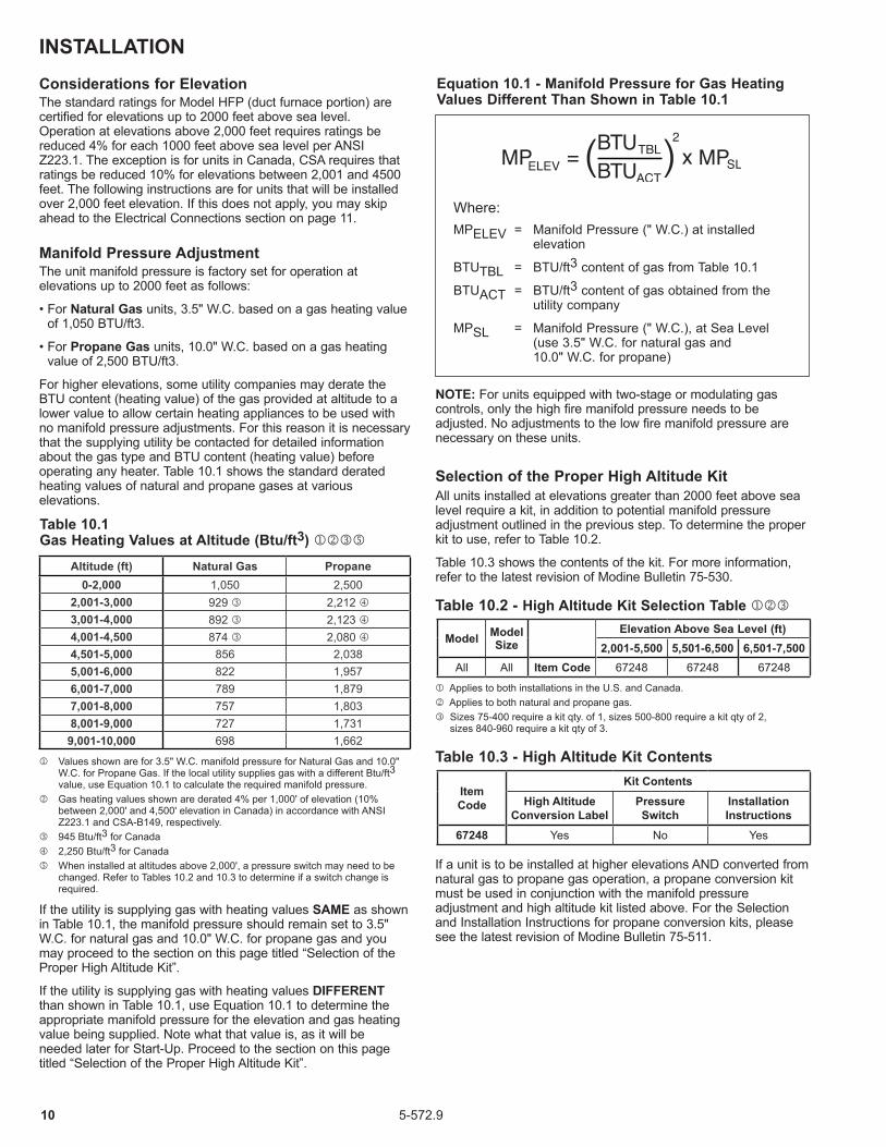
Equation 10.1 - Manifold Pressure for Gas Heating Values Different Than Shown in Table 10.1
Table 10.3 - High Altitude Kit Contents
Table 10.2 - High Altitude Kit Selection Table jkl
j Applies to both installations in the U.S. and Canada. k Applies to both natural and propane gas.l Sizes 75-400 require a kit qty. of 1, sizes 500-800 require a kit qty of 2,
sizes 840-960 require a kit qty of 3.
j Values shown are for 3.5" W.C. manifold pressure for Natural Gas and 10.0" W.C. for Propane Gas. If the local utility supplies gas with a different Btu/ft3 value, use Equation 10.1 to calculate the required manifold pressure.
k Gas heating values shown are derated 4% per 1,000' of elevation (10% between 2,000' and 4,500' elevation in Canada) in accordance with ANSI Z223.1 and CSA-B149, respectively.
l 945 Btu/ft3 for Canada m 2,250 Btu/ft3 for Canada n When installed at altitudes above 2,000', a pressure switch may need to be
changed. Refer to Tables 10.2 and 10.3 to determine if a switch change is required.
Considerations for ElevationThe standard ratings for Model HFP (duct furnace portion) are certified for elevations up to 2000 feet above sea level. Operation at elevations above 2,000 feet requires ratings be reduced 4% for each 1000 feet above sea level per ANSI Z223.1. The exception is for units in Canada, CSA requires that ratings be reduced 10% for elevations between 2,001 and 4500 feet. The following instructions are for units that will be installed over 2,000 feet elevation. If this does not apply, you may skip ahead to the Electrical Connections section on page 11.
Manifold Pressure AdjustmentThe unit manifold pressure is factory set for operation at elevations up to 2000 feet as follows:
• For Natural Gas units, 3.5" W.C. based on a gas heating value of 1,050 BTU/ft3.
• For Propane Gas units, 10.0" W.C. based on a gas heating value of 2,500 BTU/ft3.
For higher elevations, some utility companies may derate the BTU content (heating value) of the gas provided at altitude to a lower value to allow certain heating appliances to be used with no manifold pressure adjustments. For this reason it is necessary that the supplying utility be contacted for detailed information about the gas type and BTU content (heating value) before operating any heater. Table 10.1 shows the standard derated heating values of natural and propane gases at various elevations.
NOTE: For units equipped with two-stage or modulating gas controls, only the high fire manifold pressure needs to be adjusted. No adjustments to the low fire manifold pressure are necessary on these units.
Selection of the Proper High Altitude KitAll units installed at elevations greater than 2000 feet above sea level require a kit, in addition to potential manifold pressure adjustment outlined in the previous step. To determine the proper kit to use, refer to Table 10.2.
Table 10.3 shows the contents of the kit. For more information, refer to the latest revision of Modine Bulletin 75-530.
If the utility is supplying gas with heating values SAME as shown in Table 10.1, the manifold pressure should remain set to 3.5" W.C. for natural gas and 10.0" W.C. for propane gas and you may proceed to the section on this page titled “Selection of the Proper High Altitude Kit”.
If the utility is supplying gas with heating values DIFFERENT than shown in Table 10.1, use Equation 10.1 to determine the appropriate manifold pressure for the elevation and gas heating value being supplied. Note what that value is, as it will be needed later for Start-Up. Proceed to the section on this page titled “Selection of the Proper High Altitude Kit”.
If a unit is to be installed at higher elevations AND converted from natural gas to propane gas operation, a propane conversion kit must be used in conjunction with the manifold pressure adjustment and high altitude kit listed above. For the Selection and Installation Instructions for propane conversion kits, please see the latest revision of Modine Bulletin 75-511.
Table 10.1 Gas Heating Values at Altitude (Btu/ft3) jkln
Altitude (ft) Natural Gas Propane0-2,000 1,050 2,500
2,001-3,000 929 l 2,212 m 3,001-4,000 892 l 2,123 m 4,001-4,500 874 l 2,080 m 4,501-5,000 856 2,0385,001-6,000 822 1,9576,001-7,000 789 1,8797,001-8,000 757 1,8038,001-9,000 727 1,731
9,001-10,000 698 1,662
Where: MPELEV = Manifold Pressure (" W.C.) at installed
elevation
BTUTBL = BTU/ft3 content of gas from Table 10.1
BTUACT = BTU/ft3 content of gas obtained from the utility company
MPSL = Manifold Pressure (" W.C.), at Sea Level (use 3.5" W.C. for natural gas and 10.0" W.C. for propane)
INSTALLATION
Model Model Size
Elevation Above Sea Level (ft)2,001-5,500 5,501-6,500 6,501-7,500
All All Item Code 67248 67248 67248
Item Code
Kit ContentsHigh Altitude
Conversion LabelPressure Switch
Installation Instructions
67248 Yes No Yes

115-572.9
1. Installation of wiring must conform with local building codes, or in the absence of local codes, with the National Electric Code ANSI/NFPA 70 - Latest Edition. Unit must be electrically grounded in conformance to this code. In Canada, wiring must comply with CSA C22.1, Part 1, Electrical Code.
2. Two copies of the job specific wiring diagram are provided with each unit, one located in the duct furnace electrical junction box and one in the electrical section of the unit. Refer to this diagram for all wiring connections.
3. The wire gauge must be sized according to the National Electric Code or CSA code based on the power supply voltage, amp draw, and length of run. Refer to Table 11.1 for maximum wire lengths and the number of wires that can be wired to each low voltage terminal block.
UNIT INSTALLATION
WARNING1. Disconnect power supply before making wiring connections to prevent electrical shock and equipment damage.2. All appliances must be wired strictly in accordance with wiring diagram furnished with the appliance. Any wiring different from the wiring diagram could result in a hazard to persons and property.3. Any original factory wiring that requires replacement must be replaced with wiring material having a temperature rating of at least 105°C.4. Ensure that the supply voltage to the appliance, as indicated on the serial plate, is not 5% greater than rated voltage.
CAUTION1. Ensure that the supply voltage to the appliance, as indicated on the serial plate, is not 5% less than the rated voltage.
Digit 15
Transformer Size (VA)
Wire Gauge
18 Ga 16 Ga 14 Ga 12 Ga 10 Ga1 40 162 216 315 360 495
2 75 86 115 168 192 264
3 150 43 58 84 96 132
4 250 26 35 50 58 79
Maximum # of Wires per Terminal 5 4 3 2 1
Table 11.1 - Low Voltage (24V) Maximum Wire Length (ft)NEC-1996, Table 310-17, Copper wire with 90°C insulation, conductors in free space (not in conduit), 86°F ambient. For other wire types, refer to the NEC of CSA code.
Electrical Connections
4. Make sure all multi-voltage components (motors, transformers, etc.) are wired in accordance with the power supply voltage.
5. The power supply to the unit must be protected with a fused or circuit breaker disconnect switch. Refer to the Factory
Mounted Option Locations (Figure 19.1) for the factory mounted disconnect switch location and then review the unit to determine if a factory installed dead front disconnect switch was provided. Accessory field installed disconnect switches should be mounted where shown in Figure 11.2. For fusible disconnect switches, refer to the Model Identification plate for the fuse size and type.
6. The power supply must be within 5% percent of the voltage rating and each phase must be balanced within 2 percent of each other. If not, advise the utility company.
7. External electrical service connections that must be installed include:
a. Supply power (120, 208, 240, 480, or 600 volts). b. Thermostats, remote monitoring panels, building pressure
sensors, time clocks, or any other accessory control devices that may be supplied (24 volts).
8. All outdoor electrical connections must be weatherized to prevent moisture from entering the electrical compartment.
9. Refer to the unit dimensional drawings on pages 40 through 44 for the location of the drill locator dimples in the side and bottom of the unit for field drilling the hole for the electrical conduit entry.
10. All supply power electrical connections are made in the electrical section of the unit. The low voltage (thermostat and accessory control devices) can be wired to either the electrical section or the duct furnace electrical junction box. Refer to the wiring diagram for the terminal location of all low voltage wiring.
Evaporative Cooler InstallationFor units equipped with an evaporative cooler (Digit 22 = B or D), refer to Installation and Service Manual - Evaporative Coolers (Literature 5-588).
Figure 11.2 - Recommended Accessory Field Installed Disconnect Switch Mounting Locations
12 5-572.9
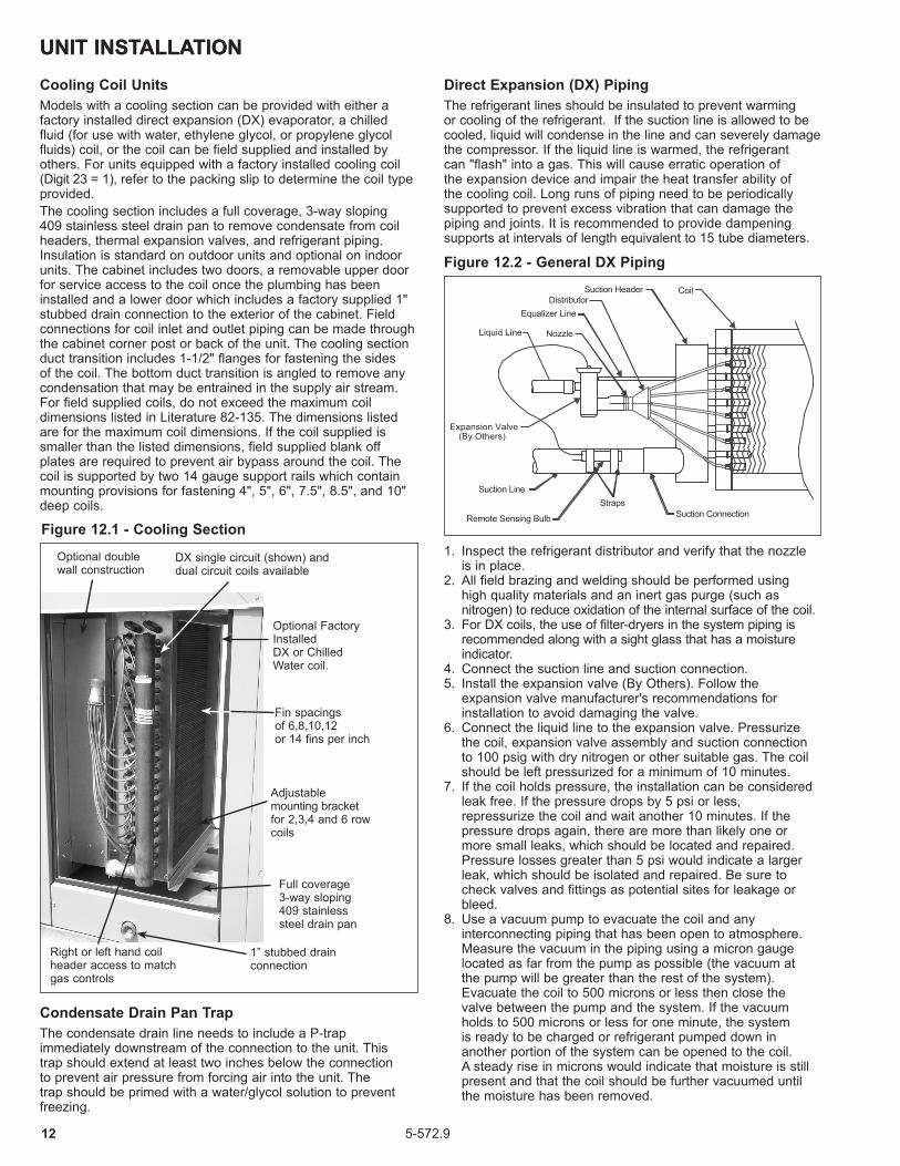
Cooling Coil UnitsModels with a cooling section can be provided with either a factory installed direct expansion (DX) evaporator, a chilled fluid (for use with water, ethylene glycol, or propylene glycol fluids) coil, or the coil can be field supplied and installed by others. For units equipped with a factory installed cooling coil (Digit 23 = 1), refer to the packing slip to determine the coil type provided. The cooling section includes a full coverage, 3-way sloping 409 stainless steel drain pan to remove condensate from coil headers, thermal expansion valves, and refrigerant piping. Insulation is standard on outdoor units and optional on indoor units. The cabinet includes two doors, a removable upper door for service access to the coil once the plumbing has been installed and a lower door which includes a factory supplied 1" stubbed drain connection to the exterior of the cabinet. Field connections for coil inlet and outlet piping can be made through the cabinet corner post or back of the unit. The cooling section duct transition includes 1-1/2" flanges for fastening the sides of the coil. The bottom duct transition is angled to remove any condensation that may be entrained in the supply air stream.For field supplied coils, do not exceed the maximum coil dimensions listed in Literature 82-135. The dimensions listed are for the maximum coil dimensions. If the coil supplied is smaller than the listed dimensions, field supplied blank off plates are required to prevent air bypass around the coil. The coil is supported by two 14 gauge support rails which contain mounting provisions for fastening 4", 5", 6", 7.5", 8.5", and 10" deep coils.
Figure 12.1 - Cooling Section
Optional double wall construction
DX single circuit (shown) and dual circuit coils available
Optional Factory InstalledDX or Chilled Water coil.
Fin spacings of 6,8,10,12or 14 fins per inch
Adjustable mounting bracket for 2,3,4 and 6 row coils
Full coverage 3-way sloping 409 stainless steel drain pan
1” stubbed drain connection
Right or left hand coil header access to match gas controls
UNIT INSTALLATIONUNIT INSTALLATION
1. Inspect the refrigerant distributor and verify that the nozzle is in place.2. All field brazing and welding should be performed using high quality materials and an inert gas purge (such as nitrogen) to reduce oxidation of the internal surface of the coil.3. For DX coils, the use of filter-dryers in the system piping is
recommended along with a sight glass that has a moisture indicator.
4. Connect the suction line and suction connection.5. Install the expansion valve (By Others). Follow the expansion valve manufacturer's recommendations for installation to avoid damaging the valve.6. Connect the liquid line to the expansion valve. Pressurize the coil, expansion valve assembly and suction connection to 100 psig with dry nitrogen or other suitable gas. The coil should be left pressurized for a minimum of 10 minutes.7. If the coil holds pressure, the installation can be considered leak free. If the pressure drops by 5 psi or less, repressurize the coil and wait another 10 minutes. If the pressure drops again, there are more than likely one or more small leaks, which should be located and repaired. Pressure losses greater than 5 psi would indicate a larger leak, which should be isolated and repaired. Be sure to check valves and fittings as potential sites for leakage or bleed.8. Use a vacuum pump to evacuate the coil and any interconnecting piping that has been open to atmosphere. Measure the vacuum in the piping using a micron gauge located as far from the pump as possible (the vacuum at the pump will be greater than the rest of the system). Evacuate the coil to 500 microns or less then close the valve between the pump and the system. If the vacuum holds to 500 microns or less for one minute, the system is ready to be charged or refrigerant pumped down in another portion of the system can be opened to the coil. A steady rise in microns would indicate that moisture is still present and that the coil should be further vacuumed until the moisture has been removed.
Suction Line
Expansion Valve
Remote Sensing Bulb
StrapsSuction Connection
CoilSuction HeaderDistributor
Equalizer Line
NozzleLiquid Line
(By Others)
Figure 12.2 - General DX Piping
Condensate Drain Pan TrapThe condensate drain line needs to include a P-trap immediately downstream of the connection to the unit. This trap should extend at least two inches below the connection to prevent air pressure from forcing air into the unit. The trap should be primed with a water/glycol solution to prevent freezing.
Direct Expansion (DX) PipingThe refrigerant lines should be insulated to prevent warming or cooling of the refrigerant. If the suction line is allowed to be cooled, liquid will condense in the line and can severely damage the compressor. If the liquid line is warmed, the refrigerant can "flash" into a gas. This will cause erratic operation of the expansion device and impair the heat transfer ability of the cooling coil. Long runs of piping need to be periodically supported to prevent excess vibration that can damage the piping and joints. It is recommended to provide dampening supports at intervals of length equivalent to 15 tube diameters.

135-572.9
UNIT INSTALLATION9. Failure to obtain a high vacuum is indicative of a great deal of moisture or a small leak. Break the vacuum with a charge of dry nitrogen or other suitable gas and recheck for leaks (soapy water works well). If no leaks are found, continue vacuuming the coil until the desired vacuum is reached.10. All field piping must be self-supporting.
Chilled Fluid PipingTo prevent noise and coil damage from water hammer, an air vent is necessary to bleed off the accumulated air in the system. The vent should be located on the top of the inlet manifold where the air collects. This vent should be opened twice a year.
The outlet manifold should have a drain installed on the bottom to allow for periodic flushing of the system to remove sediments and corrosion products from the cooling coil. This drain should be opened to allow some fluid to drain twice a year. Check coloration and viscosity of the effluent for indications of corrosion in the system. The lines between the unit and the structure should be insulated to prevent freezing of the water.
1. Once installed, the coil should be pressurized to 100 psig with dry nitrogen or other suitable gas. The coil should be left pressurized for a minimum of 10 minutes. If the coil holds the pressure, the hook-up can be considered leak free. If the pressure drops by 5 psig or less re-pressurize the coil and wait another 10 minutes. If the pressure drops again, there is more than likely one or more small leaks which should be located and repaired. Pressure losses greater than 5 psig would indicate a larger leak that should be isolated and repaired. 2. All field brazing and welding should be performed using high quality materials and an inert gas purge (such as nitrogen) to reduce oxidation of the internal surface of the coil.3. All field piping must be self supporting. System piping should be flexible enough to allow for thermal expansion and contraction of the coil.4. Fill the coil with water with all air vents open so that air is
eliminated from within the coil circuitry and headers. Verify that all vents and drains are not obstructed and do discharge a stream of water.
5. Close all vents and perform a hydrostatic leak test of all brazed, threaded or flanged joints, valves and interconnecting piping. Recheck the coil level and correct if necessary. When the setup is found to be leak free, discharge and discard initial water charge. It is important that all grease, oil, flux and sealing compounds present from the installation be removed.
Air Vent
Gate Valve
Tee
Vent PlugReturn
Air Flow
Sup
ply
Dirt Leg
CapUnion
Drain Plug
Figure 13.1 - General Chilled Fluid Piping
Table 13.1 - Cooling Coil Performance Limits
j Based on 550 feet per minute (FPM) coil face velocity.k Based on 95°F/75°F Entering Dry Bulb/Wet Bulb.l Model Size 75 minimum CFM for DX Dual Circuit is 621.m Model Size 100 minimum CFM for DX Dual Circuit is 745.
Cooling Type
Model Size
Min CFM
Single Circuit Dual Circuit Max Cooling (Tons) k
Max CFM j
Area (ft2)
Max CFM j
Area (ft2)
DX
75 688 l 1,891 3.44 1,707 3.10 9.4
100 802 m2,206 4.01 2,048 3.72 11.4
125 926
150 1,1112,521 4.58 2,416 4.39 13.4
175 1,296
200 1,4813,352 6.09 3,165 5.76 18.1
225 1,667
250 1,8523,724 6.77 3,538 6.43 20.2
300 2,222
350 2,5935,214 9.48 4,996 9.08 27.3
400 2,963
Chilled Water
75 609 1,676 3.05 n/a n/a 10.6
100 7412,011 3.66 n/a n/a 12.6
125 926
150 1,1112,372 4.31 n/a n/a 14.8
175 1,296
200 1,4813,214 5.84 n/a n/a 19.3
225 1,667
250 1,8523,592 6.53 n/a n/a 21.3
300 2,222
350 2,5935,073 9.22 n/a n/a 29.3
400 2,963

14 5-572.9
START-UP PROCEDURE
1. Turn off power to the unit at the disconnect switch. Check that fuses or circuit breakers are in place and sized correctly. Turn all hand gas valves to the “OFF” position.2. Remove the blower exterior panels and open the electrical
compartment door.3. Check that the supply voltage matches the unit supply voltage listed on the Model Identification plate. Verify that all wiring is secure and properly protected. Trace circuits to insure that the unit has been wired according to the wiring diagram.4. Check to insure that the venting system is installed and free from obstructions.5. Check to see that there are no obstructions to the intake and discharge of the unit.6. Check the belt tension and sheave alignment. Refer to Blower Adjustments for proper belt tension.7. Check bearings for proper lubrication. For units provided
with pillow block bearings (See Model Nomenclature), refer to Lubrication Recommendations for lubrication requirements.
8. Check to make sure that all filters are in place and that they are installed properly according to direction of air flow.9. Perform a visual inspection of the unit to make sure no damage has occurred during installation.10. Turn on power to the unit at the disconnect switch. Check
to insure that the voltage between duct furnace electrical box terminals 1 and 2 is 24V.
11. Check the thermostat, ignition control, gas valve, and supply fan blower motor for electrical operation. If these do not function, recheck the wiring diagram. Check to insure that none of the Control Options have tripped.12. For units with a return air damper, the return air damper linkage needs to be adjusted. Refer to Damper Linkage Adjustment.13. Check to make sure that the damper opens properly without binding.14. Check the blower wheel for proper direction of rotation when compared to the air flow direction arrow on the blower housing. Blower wheel rotation, not air movement,
must be checked as some air will be delivered through the duct furnace with the blower wheel running backwards.
15. Check the blower speed (rpm). Refer to Blower Adjustments for modification.16. Check the motor speed (rpm).17. Check the motor voltage. On three phase systems, check to make sure all legs are in balance.18. Check the motor amp draw to make sure it does not exceed the motor nameplate rating. On three phase systems, check all legs to insure system is balanced.
IMPORTANT1. To prevent premature heat exchanger failure, observe
heat exchanger tubes by looking at the heat exchanger through the field installed access openings in connecting ductwork in blower package units or the unit access doors in cooling package units. If the bottom of the tubes become red while blower and duct furnace are in operation, check to be sure the blower has been set to the proper rpm for the application. Refer to page 16 for Blower Adjustments.
2. Start-up and adjustment procedures should be performed by a qualified service agency.
19. Recheck the gas supply pressure at the field installed manual shut-off valve. The minumum inlet pressure should be 6" W.C. on natural gas and 11" W.C. on propane gas. The maximum inlet pressure for either gas is 14" W.C. If inlet pressure exceeds 14" W.C., a gas pressure regulator must be added upstream of the combination gas valve.
20. Open the field installed manual gas shut-off valve.21. Open the manual main gas valve on the combination
gas valve. Call for heat with the thermostat and allow the pilot to light for intermitent pilot ignition. If the pilot does not light, purge the pilot line. If air purging is required, disconnect the pilot line at outlet of pilot valve. In no case should line be purged into heat exchanger. Check the pilot flame length (See Pilot Flame Adjustment).
22. Once the pilot has been established, check to make sure that the main gas valve opens. Check the manifold gas pressure (See Main Gas Adjustment) and flame length (See Air Shutter Adjustment) while the supply fan blower is operating.
23. Check to insure that gas controls sequence properly (See Control Operating Sequence). Verify if the unit has any additional control devices and set according to the instructions in the Control Options.
24. Once proper operation of the unit has been verified, remove any jumper wires that were required for testing.
25. Close the electrical compartment door.26. Replace all exterior panels.Refer to page 56 for the Start-up Checklist.
Pilot Burner AdjustmentThe pilot burner is orificed to burn properly with an inlet pressure of 6-7" W.C. on natural gas and 11-14" W.C. on propane gas, but final adjustment must be made after installation. If the pilot flame is too long or large, it is possible that it may cause soot and/or impinge on the heat exchanger causing failure. If the pilot flame is shorter than shown, it may cause poor ignition and result in the controls not opening the combination gas control. A short flame can be caused by a dirty pilot orifice. Pilot flame condition should be observed periodically to assure trouble-free operation.
To Adjust the Pilot Flame1. Create a call for heat from the thermostat.2. Remove the cap from the pilot adjustment screw. For location,
see the combination gas control literature supplied with unit.3. Adjust the pilot length by turning the screw in or out
to achieve a soft steady flame 3/4" to 1" long and encompassing 3/8"-1/2" of the tip of the thermocouple or flame sensing rod (See Figure 14.1).
4. Replace the cap from the pilot adjustment screw.
3/4" to 1"
Start-Up Procedure
Figure 14.1 - Correct Pilot Flame
155-572.9
MANIFOLD TEE
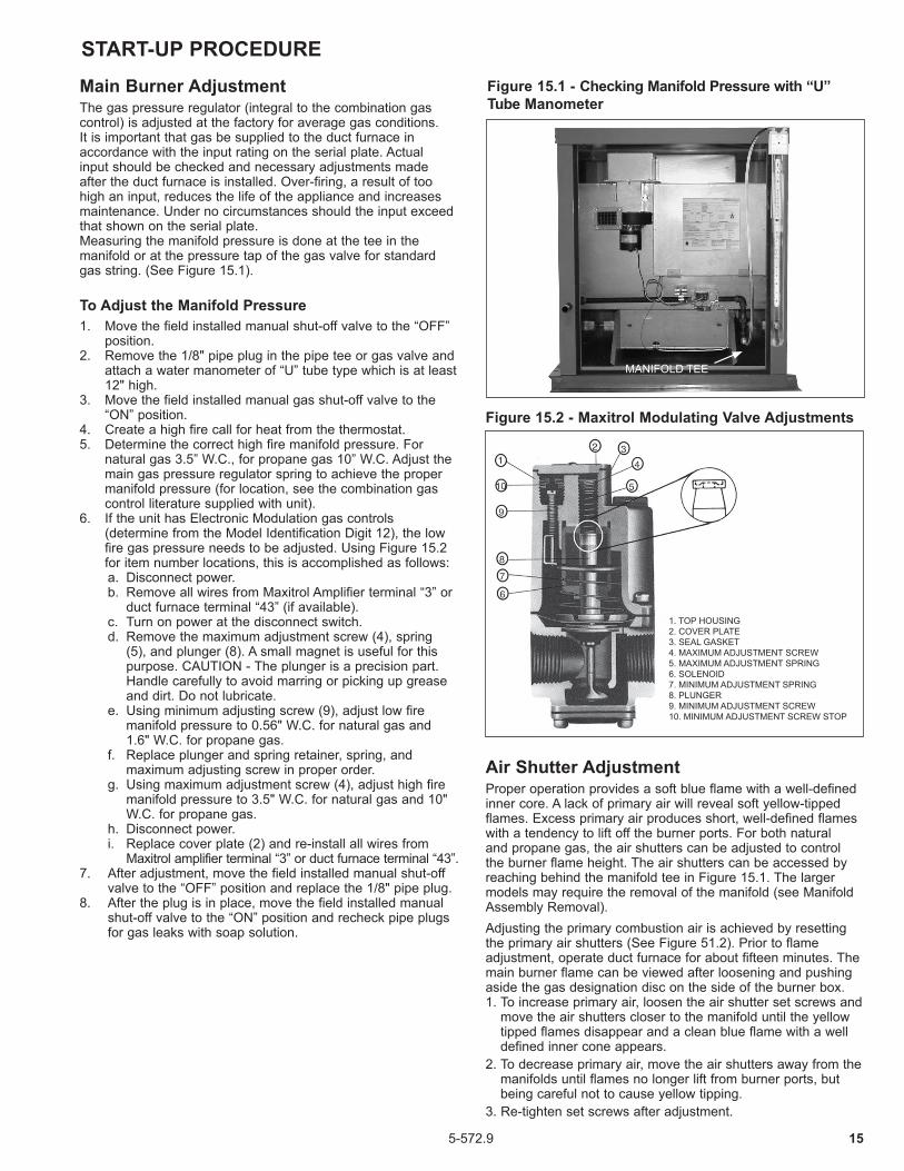
Figure 15.1 - Checking Manifold Pressure with “U” Tube Manometer
MANIFOLD TEE
START-UP PROCEDUREMain Burner AdjustmentThe gas pressure regulator (integral to the combination gas control) is adjusted at the factory for average gas conditions. It is important that gas be supplied to the duct furnace in accordance with the input rating on the serial plate. Actual input should be checked and necessary adjustments made after the duct furnace is installed. Over-firing, a result of too high an input, reduces the life of the appliance and increases maintenance. Under no circumstances should the input exceed that shown on the serial plate.Measuring the manifold pressure is done at the tee in the manifold or at the pressure tap of the gas valve for standard gas string. (See Figure 15.1). To Adjust the Manifold Pressure1. Move the field installed manual shut-off valve to the “OFF”
position.2. Remove the 1/8" pipe plug in the pipe tee or gas valve and
attach a water manometer of “U” tube type which is at least 12" high.
3. Move the field installed manual gas shut-off valve to the “ON” position.
4. Create a high fire call for heat from the thermostat.5. Determine the correct high fire manifold pressure. For
natural gas 3.5” W.C., for propane gas 10” W.C. Adjust the main gas pressure regulator spring to achieve the proper manifold pressure (for location, see the combination gas control literature supplied with unit).
6. If the unit has Electronic Modulation gas controls (determine from the Model Identification Digit 12), the low fire gas pressure needs to be adjusted. Using Figure 15.2 for item number locations, this is accomplished as follows:
a. Disconnect power. b. Remove all wires from Maxitrol Amplifier terminal “3” or
duct furnace terminal “43” (if available). c. Turn on power at the disconnect switch. d. Remove the maximum adjustment screw (4), spring
(5), and plunger (8). A small magnet is useful for this purpose. CAUTION - The plunger is a precision part. Handle carefully to avoid marring or picking up grease and dirt. Do not lubricate.
e. Using minimum adjusting screw (9), adjust low fire manifold pressure to 0.56" W.C. for natural gas and 1.6" W.C. for propane gas.
f. Replace plunger and spring retainer, spring, and maximum adjusting screw in proper order.
g. Using maximum adjustment screw (4), adjust high fire manifold pressure to 3.5" W.C. for natural gas and 10" W.C. for propane gas.
h. Disconnect power. i. Replace cover plate (2) and re-install all wires from
Maxitrol amplifier terminal “3” or duct furnace terminal “43”.7. After adjustment, move the field installed manual shut-off
valve to the “OFF” position and replace the 1/8" pipe plug.8. After the plug is in place, move the field installed manual
shut-off valve to the “ON” position and recheck pipe plugs for gas leaks with soap solution.
Air Shutter AdjustmentProper operation provides a soft blue flame with a well-defined inner core. A lack of primary air will reveal soft yellow-tipped flames. Excess primary air produces short, well-defined flames with a tendency to lift off the burner ports. For both natural and propane gas, the air shutters can be adjusted to control the burner flame height. The air shutters can be accessed by reaching behind the manifold tee in Figure 15.1. The larger models may require the removal of the manifold (see Manifold Assembly Removal). Adjusting the primary combustion air is achieved by resetting the primary air shutters (See Figure 51.2). Prior to flame adjustment, operate duct furnace for about fifteen minutes. The main burner flame can be viewed after loosening and pushing aside the gas designation disc on the side of the burner box.1. To increase primary air, loosen the air shutter set screws and
move the air shutters closer to the manifold until the yellow tipped flames disappear and a clean blue flame with a well defined inner cone appears.
2. To decrease primary air, move the air shutters away from the manifolds until flames no longer lift from burner ports, but being careful not to cause yellow tipping.
3. Re-tighten set screws after adjustment.
Figure 15.2 - Maxitrol Modulating Valve Adjustments
1. TOP HOUSING2. COVER PLATE3. SEAL GASKET4. MAXIMUM ADJUSTMENT SCREW5. MAXIMUM ADJUSTMENT SPRING6. SOLENOID7. MINIMUM ADJUSTMENT SPRING8. PLUNGER9. MINIMUM ADJUSTMENT SCREW10. MINIMUM ADJUSTMENT SCREW STOP

16 5-572.9
START-UP PROCEDUREBlower AdjustmentsIf blower fan speed changes are required, adjust motor sheave as follows:1. Refer to page 32 to determine correct blower speed
according to job requirements, then proceed with steps 2 through 8.
2. Loosen motor base and take belt off of motor sheave.3. Loosen set screw on outer side of adjustable motor sheave.
4. Turn outer side of motor sheave clockwise until motor sheave is fully closed.
5. From fully closed position, turn outer side of motor sheave counterclockwise until the proper number of turns open are achieved.
6. Retighten motor sheave set screw, replace belt and retighten motor base. Motor base should be shifted for proper belt tension which is 3/4" deflection with about 5 lbs. of force.
Toward Motor
Set Screw
Adjustable Halfof Sheave
Figure 16.1 - Motor Sheave Adjustment
3/4" deflectionwith 5 lbs. of force
ñ
Figure 16.2 - Belt Tension Adjustment
Damper Linkage AdjustmentIf the unit is provided with a return air damper, to prevent shipping damage, the return air damper linkage is disconnected and the damper closed. Before operating the unit, the fresh and return air dampers must be connected. This is accomplished by the following:1. The damper actuator should be de-energized and the fresh
air damper in a fully closed position.2. Open the return air damper in a fully open position.3. Slide the connecting rod into the ball joint on the blade arm
with the return air damper fully open. See Figure 16.3.4. Tighten the 5/16" hex head screw on the ball joint.
Figure 16.3 - Damper Linkage Adjustment
DAMPERBLADE
BALL JOINT CONNECTING ROD
BLADE ARM
7. Recheck blower rpm after adjustment. NOTE: Do not fire unit until blower adjustment has been
made or unit may cycle on high limit control.8. Check motor amps. Do not exceed nameplate amps shown
on motor nameplate.
Cooling Coil Operation1. Proper air distribution is vital to coil performance. Air flow
anywhere on the coil face should not vary by more than 20%.2. Air velocities should be maintained between 200 and 550
feet per minute.3. For chilled fluid coils, fluid velocities should be maintained
within the recommended values of 1 to 8 feet per second (fps) for Water and 1 to 6 fps for Glycol solutions.
Lubrication RecommendationsThe blower can be provided with either spider or pillow block bearings. Spider bearings are permanently lubricated and do not require lubrication. Pillow block bearings are shipped greased from the factory but will require lubrication. The bearings should be checked and lubricated before each heating season but a more frequent lubrication schedule may be required based on the environment in which the unit is installed, and the frequency of the equipment operation. Shell Alvania #2 lubricant is recommended.

175-572.9
START- UP PROCEDURE
Indoor duct furnaces are supplied with intermittent pilot systems with continuous retry, which both the main burner and pilot burner are turned off 100% when the thermostat is satisfied. On a call for heat, the system will attempt to light the pilot for 70 seconds. If the pilot is not sensed for any reason, the ignition control will wait for approximately six minutes with the combination gas control closed and no spark. After six minutes, the cycle will begin again. After three cycles, some ignition controllers lockout for approximately one hour before the cycle begins again. This will continue indefinitely until the pilot flame is sensed or power is interrupted to the system. Note: Gas Control Options (see page 19) could change the listed sequence of operation based on their function.The descriptions given are for the basic duct furnace.
IMPORTANTTo prevent premature heat exchanger failure, with all control systems, a blower starting mechanism must be provided so that the blower is running or energized within 45 seconds of the gas control operation.
Control Operating Sequence
Single Furnace ControlsStaged Control (Digit 12=1 or 2): These units utilize a single- or two-stage combination gas valve, an ignition control, and a low voltage thermostat.
Electronic Modulating Control (Digit 12=4, 7, or 8): These units utilize a single-stage combination gas valve, an electronic modulating gas valve, a modulating amplifier, an ignition control, and one of the following:• Modulating room thermostat• Modulating duct thermostat with remote temperature set point
adjuster• Building Management System (BMS) signal by others (an
inverted signal where 0 VDC or 4 mA is high fire and 10 VDC or 20 mA is low fire).
The control operating sequence for all units is as follows:
1. The thermostat calls for heat. For BMS controlled units, the BMS closes a heat enable contact at the unit.
2. The power exhauster relay is energized starting the power exhauster motor. Once the motor has reached full speed, the differential pressure switch closes. The power exhauster pre-purge time delay relay then closes after 20 to 40 seconds and energizes the gas control circuit.
3. The pilot valve opens and the spark igniter sparks in an attempt to light the pilot. (If the unit was not provided with a time delay relay, the blower starts).
4. Once the pilot is lit, the flame sensor proves the pilot and stops the spark igniter from sparking.
5. The main gas valve is opened and the main burner is controlled as follows:
a. Single-Stage Units: The main burner is lit to 100% full fire. b. Two-Stage Units: The main burner is lit to 50% fire. If
the temperature at the thermostat continues to fall, the thermostat will call for high stage heat and the main burner is lit to 100% full fire.
c. Modulating Thermostat (Room or Duct): The main gas valve is opened 100% and the burner firing rate is modulated between 40% and 100% full fire. A resistance signal (8000 to 12000 ohms) in the thermostat is converted by the modulating amplifier to an inverted DC voltage
(0VDC for high fire to 12 VDC for low fire). The output voltage is applied to the modulating gas valve to control the gas flow to the main burner. The modulating valve is modulated open or closed based on the voltage from the amplifier (less gas flow required = higher voltage, more gas flow required = lower voltage).
Note: When modulating duct sensing is utilized, a room override thermostat can be added. When the room override calls for heat, the burner modulates to full fire operation until the room override is satisfied. The unit then reverts back to duct sensing control. When equipped with both, either the duct sensor or the room override thermostat can call for heat.
d. BMS Signal: The main gas valve is opened 100% and the burner firing rate is modulated between 40% and 100% full fire. A BMS 0-10VDC or 4-20mA signal (inverted, such that 0 VDC or 4 mA is high fire and 10 VDC or 20 mA is low fire) is converted by the signal conditioner/modulating amplifier into an inverted DC voltage (0VDC for high fire to 12 VDC for low fire). The output voltage is applied to the modulating gas valve to control the gas flow to the main burner. The signal conditioner can accept a 0-10 VDC signal when all the dip switches are in the “OFF” position and 4-20 mA signal when all the dip switches are in the “ON” position. The modulating valve is modulated open or closed based on the voltage from the amplifier (less gas flow required = higher voltage, more gas flow required = lower voltage), which correlates to the control signal from the BMS.
Note: For further information regarding the operation of any of the electronic modulating system options above, consult the literature provided with the unit.
6. If the unit was provided with a time delay relay, the blower starts after 30 to 45 seconds.
7. The unit continues to operate until the thermostat is satisfied, Once satisfied:
a. Single-Stage Units: Both the main and pilot valves close 100%.
b. Two-Stage Units: Once the high stage of the thermostat is satisfied, the main valve closes to 50% fire. The unit continues to operate until the low stage thermostat is satisfied, at which time both the main and pilot valves close 100%.
c. Electronic Modulation Units: The unit continues to operate in this manner until the thermostat is satisfied or the BMS heat enable contact opens. Power is then cut to both the main and pilot valves, closing them 100% and stopping gas flow to the main and pilot burners.
8. If the unit was not provided with a time delay relay, the blower stops immediately. If the unit was provided with a time delay relay, the blower stops after 30 to 45 seconds.
18 5-572.9
START-UP PROCEDURE
Multiple Furnace ControlsStaged Control (Digit 12=1): For control of multiple staged units, each furnace would be individually controlled. Refer to the section for Single Furnace Controls, Staged Control (Digit 12=1 or 2).
Electronic Modulating Control (Digit 12=4): These units are the same as Electronic Modulating Gas Controls – Single Furnace (Digit 12=4) except the Master unit features a modulating amplifier capable of driving multiple modulating gas valves for systems with a Master and up to two Slave units. Slave units do not have a modulating amplifier. The units would be controlled by one of the following:• Modulating room thermostat• Modulating duct thermostat with remote temperature set point
adjuster
The sequence of operation for Electronic Modulating Gas Controls - Master/Slave is the same as Electronic Modulating Gas Controls - Single Furnace. The modulating amplifier sends an equal voltage signal to all of the modulating gas valves so that they modulate at the same percentage, between 40% and 100% full fire.
Electronic Modulating Control (Digit 12=7, or 8): For control of multiple electronic modulation units for BMS control, each furnace would be individually controlled. Refer to the section for Single Furnace Controls, Electronic Modulation Control (Digit 12=7 or 8).
Variable Air Movement ApplicationsUnits may be supplied with variable frequency drives for applications where variable air volume is required. The minimum air flow may be varied between 30 and 100% of the full speed air flow depending on the controls selection of the unit. Due to the extra restrictions of the controller all selections must be performed with the AccuSpec configuration software. Within AccuSpec, three variable frequency drive speed control changeover options are available: 1. Two speed which may be controlled by a manual high/low
switch which may be factory mounted on the control panel or shipped loose for field installation or by exhaust fan interlocks.
2. Floating building pressure sensing which utilizes a photohelic pressure controller to adjust the building pressure by varying the amount of makeup air supplied to the the space.
3. Building management control which allows for an external signal of 0-10VDC of 4-20mA to adjust the unit airflow.
The allowable minimum CFM of the system can be 66% of the minimum listed CFM in Table 27.1 if the unit is applied as follows: 1. The unit is provided with 2-stage or electronic modulating
gas controls. 2. The unit is provided with a discharge air thermostat. 3. The system does not include a room thermostat.The discharge air thermostat will prevent the unit from firing above the allowable 100°F rise when the unit is at or above the minimum CFM by monitoring the discharge air and going to low fire. A room thermostat, because it is located remote from the unit, could cause the unit to over-fire.

195-572.9
OPTIONS - FACTORY INSTALLED
1. Discharge Thermostat2. Low Gas Pressure Switch3. High Gas Pressure Switch4. Power Exhauster5. Timed Freeze Protection6. Ignition Controller8. Control Relay9. Time Delay Relay10. Furnace Low Voltage Terminal Strip11. Power Exhauster Relay12. Furnace Supply Power Terminal Strip13. Control Step Down Transformer14. Control Relay15. Blower Low Voltage Terminal Strip16. Dead Front Disconnect Switch17. Step Down Transformer Fuses18. Step Down Transformer19. Factory Installed Minimum Positioner20. Extended Grease Line Zerk Fittings21. Extended Grease Lines22. Return Air Fire Stat23. Blower Housing24. Pillow Block Bearings25. Blower Motor26. Filters27. Fresh Air Damper28. Enthalpy Sensor29. Rainhood and Birdscreen30. Direct Drive Damper Actuator31. Enthalpy Controller32. Damper to Damper Linkage
33. Return Air Damper34. Proportional Temp Controller Sensor35. Motor and Blower Vibration Isolation36. Blower Support37. Convenience Outlet38. Blower Door Switch39. Dirty Filter Switch40. Motor Starter/VFD Control41. Mild Temperature Thermostat42. Proportional Temp Controller43. Warm-Up Stat
44. Blower Supply Power Terminal Strip45. Service Switches46. Electronic Modulating Amplifier47. Electronic Modulating Gas Valve48. Air Flow Proving Switch49. High Limit Switch50. Supply Air Fire Stat51. Main Gas Valve52. Burner Box53. Direct Drive Damper Actuator54. Discharge Damper
Figure 19.1 - Factory Mounted Option Locations
All units include the standard (STD) features. The unit must be reviewed to determine the optional (OPT) features that may have been supplied with the unit.
(1) Discharge Thermostat – (OPT) (Not Shown)The discharge thermostat is field installed in the discharge air stream of the unit. For additional information, refer to the thermostat vendor literature provided in the literature packet with the unit. Model Sizes 500-960 contain multiple furnaces so multiple thermostats/sensors may be included. The thermostat(s) provided can be one of the following:
a) Two-stage Capillary Type Thermostat – The thermostat includes a thermostat body and capilary to be field installed in duct work. The thermostat body contains the discharge air set point adjuster that must be field set.
(Shown with cover removed)Thermostat body
R B W
WBR
Left
Right
AdjusterSetpoint
Downstream Ductwork(by others)
Capillary
Figure 19.2 - Two-Stage Capillary Type Thermostat

20 5-572.9
b) Two-stage Electronic Type Thermostat - Includes a field installed discharge air sensor. The thermostat body is field installed remotely and includes the discharge air set point adjuster that must be field set. Refer to Literature 5-577 latest revision.
Figure 20.1 - Two-Stage Electronic Type Thermostat Sensor
c) Electronic Modulating Discharge Air Thermostat – Includes a field installed mixing tube and discharge air sensor field installed in duct work. The set point adjuster is field installed remotely and must be field set. Refer to Literature 5-578 latest revision.
Figure 20.2 - Electronic Modulating Discharge Air Thermostat
(2) Low Gas Pressure Switch – (OPT)The low gas pressure switch is factory installed in the duct furnace above the gas train. The switch monitors the gas pressure upstream of all the gas controls and shuts off the electric supply to the ignition controller and combination gas valve if low gas pressure is experienced. This will shut off all gas flow to the burner. The switch has an automatic reset so that if the gas pressure is interrupted and then is returned, the switch will automatically allow the unit to operate when gas conditions are returned to the allowable range of the pressure switch. The pressure switch range is 2" to 14" W.C. and should be set to insure that the minimum inlet gas pressure is available (6" W.C. for natural gas, 11" W.C. for propane gas).
(3) High Gas Pressure Switch – (OPT)The high gas pressure switch is factory installed in the duct furnace above the gas train. The switch monitors the gas pressure downstream of all the gas controls and shuts off the electric supply to the ignition controller and combination gas valve if high gas pressure is experienced right before the manifold. This will shut off all gas flow to the burner. The switch has a manual reset so that if the gas pressure is too high, a service person must check the unit to make sure that none of the gas controls have been damaged by the high gas pressure and then reset the switch to allow the unit to operate when gas
conditions are returned to the allowable range of the pressure switch. The pressure switch range is 2" to 16" W.C. and should be set to insure that the maximum manifold gas pressure is not exceeded (3.5" W.C. for natural gas, 10" W.C. for propane gas). (4) Power Exhauster – (STD)The power exhauster is factory installed in the duct furnace section. On a call for heat, the power exhauster creates a combustion draft through the duct furnace prior to the pilot being energized. The draft is proven through the power exhauster motor centrifugal switch that closes when the motor reaches full speed. The unit door includes a factory installed power exhauster discharge cover and inlet combustion louvers. For information about venting, refer to the Installation – Venting section. (5) Timed Freeze Protection – (OPT)The timed freeze protection system is factory installed in the duct furnace electrical junction box with the sensor (30°-75°F adjustable) factory installed in the discharge air stream. On initial start-up, the timed delay in the system allows the unit to go through the normal ignition sequence. The timed delay is a manual reset switch and adjustable for 1-10 minutes. In the event that the unit fails to fire after this period, the discharge air sensor will sense the cold air and will shut down the entire unit.
OPTIONS
Figure 20.4 - Timed Freeze Protection Module
Figure 20.3 - Low or High Gas Pressure Switch
(6) Ignition Controller – (STD)The ignition controller is factory installed in the duct furnace electrical junction box with the spark ignitor and sensor located on the burner. For both natural and propane gas units, the ignition controller is 100% shut-off with continuous retry. On a call for heat, the system will attempt to light the pilot for 70 seconds. If the pilot is not sensed for any reason, the ignition control will wait for approx imately six minutes with the combination gas control closed and no spark. After six minutes, the cycle will begin again. After three cycles, some ignition controllers lockout for approximately one hour before the cycle begins again. This will continue indefinitely until the pilot flame is sensed or power is interrupted to the system.
Note: Second stage S350 module not shown.

215-572.9
(8) Control Relay – (OPT)The control relay is factory installed in the duct furnace electrical junction box. The relay has a 24V coil with double-pole, double throw (DPDT) contacts. Refer to the unit wiring diagram for the function of the switching operation of the relay. The two normally open and two normally closed contacts are rated for a maximum of 30 amps @ 115V/1Ph.
(9) Time Delay Relay – (STD)The time delay relay is factory installed in the duct furnace electrical junction box. The time delay relay allows the gas controls to operate for approximately 30 seconds before the blower starts. This allows the heat exchanger a warm up period so that the initial delivered air coming out of the ductwork is not cool. The time delay relay also keeps the motor running for approximately 30 seconds after the call for heat has been satis fied to remove the residual heat from the heat exchanger. For single phase units below 1-1/2 Hp, the time delay relay controls the motor directly. For single phase units 1-1/2 Hp and greater and all three phase units, the time delay relay controls the motor starter.
(10) Furnace Low Voltage Terminal Strip – (STD)The furnace low voltage terminal strip is located in the duct furnace electrical junction box. The terminal strip is labeled to match the electrical wiring diagram provided with the unit. Low voltage labeling ranges from terminal numbers 1 to 79. All field wiring connections should be made to the top side of the terminals to prevent miswiring by modifying the factory wiring which is made to the bottom of the terminal strip.
(11) Power Exhaust Relay – (STD)The control relay is factory installed in the duct furnace electrical junction box. The relay has a 24v coil with single-pole single throw (SPST) contacts. On a call for heat, the relay coil is energized resulting in the contacts energizing the power exhauster motor.
(12) Furnace Supply Power Terminal Strip – (STD)The furnace supply power terminal strip is located in the duct furnace electrical junction box. The terminal strip is labeled to match the electrical wiring diagram provided with the unit. Supply power labeling ranges from terminal numbers 80 to 99. All field wiring connections should be made to the bottom side of the terminals to prevent miswiring by modifying the factory wiring which is made to the top of the terminal strip.
(13) Control Step Down Transformer – (STD)The control step down transformer is located in the duct furnace electrical junction box. The transformer is used to step down the supply power (115V, 208V, 230V, 460V, 575V) to 24V. This transformer is used to control the gas controls, damper actuator, motor starter, etc. Refer to the unit model number to determine the volt- amp (VA) capacity of the duct furnace. The 15th digit indicates the VA (See Model Nomenclature).
(14) Control Relay – (OPT)The control relay is factory installed in the electrical section. See description of Option 8 for additional details.
(15) Blower Low Voltage Terminal Strip – (STD)The blower low voltage terminal strip is located in the electrical section. The terminal strip is labeled to match the electrical wiring diagram provided with the unit. Low voltage labeling ranges from terminal numbers 1 to 79. All field wiring connections should be made to the right side of the terminals to prevent miswiring by modifying the factory wiring which is made to the left side of the terminal strip.
OPTIONS(16) Dead Front Disconnect Switch – (OPT)
WARNINGWhen the dead front disconnect switch is in the “OFF” position, supply power remains energized at the blower supply power terminal strip and the top of the dead front disconnect switch. When providing service on or near these terminals, building supply power to the unit should be de-energized.
Figure 21.1 - Dead Front Disconnect Switch Assembly
SUPPLY POWERWIRING TERMINALS
(SEE WARNING)
BLOWER SECTIONELECTRICAL
COMPARTMENTACCESS DOOR
DISCONNECTSWITCH HANDLE
OPERATIONINSTRUCTION
LABEL
BLOWER SECTIONELECTRICAL
COMPARTMENTSTAND-OFF PANEL
DISCONNECTSWITCH HANDLESHOWN IN THE"ON" POSITION
DISCONNECTSWITCH HANDLESHOWN IN THE"OFF" POSITION
The dead front disconnect switch is factory installed in the electrical section. The disconnect switch is designed so that it must be turned “OFF” before entry to the electrical control cabinet can be obtained (See Figure 21.1). When in the “OFF” position, power is disconnected to all unit wiring electrically following the switch (See Warning). For servicing the unit, the disconnect switch can be manually overridden by using a wrench and turning the disconnect switch shaft 90° clockwise (See Figure 21.1). Fusible and circuit breaker switches available. For fusible switches, Class “J” time delay fuses must be field provided matching the fuse size listed on the Model Identification plate.
(17) Step Down Transformer Fuses – (OPT)The transformer fuses are factory installed in the electrical section. The fuses are included to protect the transformer. Fuses included.(18) Step Down Transformer – (OPT)The step down transformer is factory installed in the eletrical section. The transformer is required for power exhausted units (Digit 2 = P) with a supply voltage of 460V/3Ph and 575V/3Ph and all units that have an evaporative cooler (Digit 22 = 3,4,5, or 6).For all units with an evaporative cooler, when the supply power voltage is 208V/1Ph or 208V/3Ph, the transformer is provided to step down the voltage from 208V to 115V. In this case, the evaporative cooler pump motor operates at 115V. For power exhausted units and all units with an evaporative cooler, when the supply power voltage is 460V/3Ph or 575V/3Ph, the transformer is provided to step down from supply power voltage to 115V. In this case, the evaporative cooler pump motor operates at 115V.

22 5-572.9
(20, 21) Extended Grease Lines – (OPT)The extended grease lines (21) are factory installed in the blower section and include Zerk® grease fittings (20) factory installed on the exterior corner post between the electrical and blower sections. This option allows the pillow block bearings to be lubricated with a grease gun without requiring the service personnel to remove both blower doors to access the bearings. Refer to Lubrication Recommendations for lubricant recommendations.
(22) Return Air Fire Stat – (OPT)The return air fire stat is factory installed in the electrical section with the sensor in the return air stream. In case of elevated temperatures in the return air stream, the manual reset switch shuts down the entire unit. If the limit temperature is exceeded, a service person must inspect the unit for the cause of the high discharge temperature, take corrective action, and then reset the switch.
(23) Blower Housing – (STD)The blower housing is factory installed in the blower section. The blower housing contains a double width, double inlet (DWDI) blower wheel so both sides of the blower must be free from obstructions for proper operation. For Right Hand units (Digit 9 = R), during operation the blower wheel should rotate in the clockwise direction when viewed from the service side of the unit. For Left Hand units (Digit 9 = L), during operation the blower wheel should rotate in the counterclockwise direction when viewed from the service side of the unit. If necessary, interchange supply power wiring to reverse blower rotation.
(24) Pillow Block Bearings – (OPT)The blower bearings are factory installed in the blower section. The blower can be provided with either spider or pillow block bearings. Spider bearings are permanently lubricated and do not require lubrication. Pillow block bearings are shipped non-greased from the factory and require lubrication before start-up. For lubrication recommendations, see Lubrication Recommendations.
(25) Blower Motor – (STD)The blower motor is factory installed in the blower section. The blower motor can be provided in a variety of supply voltages, frame types, and motor horsepowers. Refer to the model nomenclature to determine the type of motor provided. The
OPTIONSblower motor is supplied with an adjustable sheave that can be used to increase/decrease the blower RPM. For instructions on changing the blower RPM, refer to Blower Adjustments.
(26) Filters – (OPT)When filters are supplied with the unit, a rack and the filters are factory installed in the blower section. The unit can be supplied with 1" or 2" permanent filters, 2" FARR® Aeropleat MERV 7 or 2" FARR® 30/30 MERV 8 filters. For filter replacement, refer to Maintenance.
(27) Fresh Air Damper – (OPT)When a fresh air damper is supplied with the unit, the damper is factory installed in the blower section. The fresh air damper is used as an outside air shut-off damper, so ultra low leak, Class II leakage resistance (less than 10 CFM/ft2 at 1" W.C.) dampers with self-compensating stainless steel side seals and santoprene and galvanized steel blade seals are used.
(29) Rainhood and Birdscreen – (OPT)The rainhood and birdscreen is shipped loose for field installation at the back of the blower section. For installation instructions, refer to Literature 5-589 supplied with the rainhood and birdscreen.
(30) Direct Drive Damper Actuator – (OPT)The direct drive damper actuator is factory installed in the blower section on the side of the fresh air damper. The actuator controls the position of the fresh air damper. The return air damper, if provided, is controlled by the damper linkage between the two dampers. All damper actuators are low voltage (24V). For Right Hand units (Digit 9 = R), during operation the actuator should rotate in the counterclockwise direction when viewed from the service side of the unit. For Left Hand units (Digit 9 = L), during operation the actuator should rotate in the clockwise direction when viewed from the service side of the unit. Three different types of dampers actuators can be provided: Two-position, Modulating, and Floating.
Two-position Damper Actuator: A two-position damper actuator is provided with Air Control options DA, EA and EQ (Digits 20 & 21). The two-position damper actuator provides open/ closed operation of the fresh air damper. When the damper is energized, the fresh air damper is opened to 100% outside air in 75 seconds (for outside air percentages lower than 100%, refer to the following section, "Setting the Damper Limiter"). All two-position damper actuators are spring return, so when the damper is de-energized, the fresh air damper will spring closed. All two-position dampers include auxiliary switches (one normally open and one normally closed) that reverse when the damper actuator is at 85° rotation (adjustable).
Setting the Damper Limiter: The two-position damper limiter is factory set to prevent the outside air damper from opening 100%. Field adjustment of the two-position damper limiter is accom plished by the following:1. Determine the amount of damper rotation required
(Percentage of outside air).2. Locate the angle of rotation limiter on the actuator so that its
edge lines up with the degree graduation on the actuator face which corresponds with the required rotation. (See Figure 23.1 which is shown at 50% rotation limit.)
3. Position the limiter back to the desired position, making sure the locating “teeth” on the limiter are engaged into the locating holes on the actuator.
4. Fasten the limiter to the actuator using the screw provided.5. Test the damper rotation either manually with the manual
crank or apply power. Re-adjust if necessary.6. If the damper end switch is being used in the control circuit
and needs to be adjusted for the new minimum position, refer to the next section, "Adjusting the Damper End Switch".
%
Belimo
60
8010
0
40
200
Figure 22.2 - Minimum Positioner
(19) Factory Installed Minimum Positioner – (OPT)The factory installed minimum positioner is installed in the electrical section and is used with a modulating damper actuator to set the minimum percentage of outside air. The minimum positioner dial is manually set between 0 to 100% resulting in a 2 to 10 VDC signal being sent to the damper actuator. When used in conjunction with the Proportional Temp Controller, the positioner sets the minimum outside air percentage and the Proportional Temp Controller then modulates between the minimum position and 100% outside air.

235-572.9
Figure 23.1 - Two-position Damper Actuator and Limiter
Adjusting the Damper End SwitchIf the damper limiter was adjusted in the previous section, it may be required to adjust the Damper End Switch as follows:1 The actuator must be in its fail-safe position.2. Insert the crank handle into the torx shaped hole located in
the center of the adjustable switch pointer as shown in Figure 23.2.
3. Gently rotate the crank until the switch pointer is at the desired switch point in degrees as shown.
OPTIONSclosure which electrically drives the damper closed. If the supply power to the unit is interrupted before the damper actuator can drive closed, the fresh air damper will remain open. The damper can be manually closed through the use of the manual override switch on the floating damper actuator.
(31) Enthalpy Controller – (OPT)An enthalpy controller is provided with Air Control option GJ (Digits 20 & 21) and factory installed in the blower section. The purpose of the enthalpy controller is to use outside air for cooling, whenever possible, to reduce compressor operation of the mechanical cooling system. The economizer functions as a true first stage of cooling and provides maximum fuel economy during the cooling cycle. The components used for the Enthalpy Economizer are:• Enthalpy Economizer Controller. The Enthalpy Controller is
used in conjunction with the Enthalpy Sensor and a Mixed Air Temperature sensor. The controller is factory mounted in the blower control cabinet.
• Outside Air Enthalpy Sensor. The sensor provides a signal in relation to enthalpy (temperature and humidity) of the outside air. The sensor is installed in the outside air stream.
• Mixed Air Temperature Sensor. The sensor is factory installed in the blower section to sense the mixed air temperature of the fresh and return air streams.
Typical Sequence of OperationHeating or Ventilation ModeWhen the space thermostat calls for heat or the fan is on without a call for cooling (ventilation mode), the economizer is automatically locked out and holds the outdoor air damper at the minimum position setting. The minimum position adjustment keeps the outdoor air damper from closing completely during system operation to provide ventilation in both the heating and cooling modes. Cooling ModeWhen the space thermostat calls for cooling, the system operates as follows:
Outdoor Air Enthalpy is Below Changeover Set Point1. The outdoor air damper is proportioned open (and the
return air damper is proportioned closed) to maintain a temperature of 53°F (default, adjustable) at the mixed temperature air sensor.
2. During economizer operation, mechanical cooling is operated by the second stage of the cooling on the space thermostat.
Outdoor Air Enthalpy is Above Changeover Set Point1. The outdoor air damper is closed to its minimum position.2. A call for cooling from the space thermostat brings on
mechanical cooling. For complete details on the Enthalpy Economizer controller setup and operation, please refer to the latest revision of Modine publication 5-598, "Setup Instructions, Enthalpy Economizer Controller".
Figure 23.2 - Adjusting the Damper End Switch
Modulating Damper Actuator: A modulating damper actuator is provided with Air Control options GA, GB, GC, GD, GE, GG, GH, GJ, GK and GM (Digits 20 & 21). The modulating damper actuator provides incremental operation of the fresh air damper (The return air damper is controlled by the fresh air damper position). Full 90° rotation of the modulating actuator requires 150 seconds. All modulating damper actuators operate using a 0-10 Vdc input signal (Air Control GB utilizes a resistor to convert from a 4-20 mA to 0-10 Vdc) from a damper controller. All modulating damper actuators are spring return, so when the damper is de-energized, the fresh air damper will spring closed.Floating Damper Actuator: A floating damper actuator is provided with Air Control option HP (Digits 20 & 21). The floating damper actuator provides forward and reversing damper operation in response to contact closures from the space pressure controller. When the space pressure is above the desired set point, a high pressure contact on the space pressure controller energizes the damper to drive the fresh air damper closed. When the space pressure is below the desired set point, a low pressure contact on the space pressure controller energizes the damper to drive the fresh air damper open. When the space pressure is between the high and low set points, the damper “floats” at the fresh air percentage that satisfied the space pressure controller. Full 90° rotation of the floating actuator requires 150 seconds. For additional information on the space pressure controller, refer to Literature 5-585.The damper actuator is designed to “float” and therefore it is not spring return. When the unit is de-energized under normal operation, the fresh air damper is closed by a relay contact
Figure 23.3 - Enthalpy Controller

24 5-572.9
(39) Dirty Filter Switch – (OPT)The dirty filter pressure switch is factory installed in the electrical section. The dirty filter pressure switch monitors the pressure differential between the two sides of the filters. When the filters become dirty, the differential pressure increases and trips the pressure switch which energizes a light on the remote monitoring panel. The pressure differential switch must be field set because setting the switch requires the blower to be in operation and the ductwork to be installed.
Setting the Dirty Filter SwitchThe range of the dirty filter pressure switch is adjustable between 0.17" to 5.0" W.C.1. Ensure that the unit filters are clean. Clean or replace if
necessary.2. Connect the leads of a continuity tester to the NO and C
terminals of the dirty filter pressure switch. See Figure 25.13. Set the thermostat so that there is a call for heat. This should
fire the burner and the blower should start.4. Turn the set screw of the pressure switch clockwise until
it stops. This will set the pressure at 5.0" W.C. and the continuity tester should be sensing an open circuit.
5. Begin turning the screw counterclockwise until the continuity tester senses a closed circuit. This determines the base pressure of the system.
6. Turn the screw clockwise until the continuity tester senses an open circuit and then one additional full turn (This is approx-imately 0.25" W.C.) This will allow for the increase in static pressure due to dirty filters.
The convenience outlet is factory installed in the blower section for providing power for 115V service equipment (trouble light, power tools, etc.). The 115V ground fault circuit interrupter (GFCI) is rated for 15 amps and includes test and reset switches. A separate field supplied 115V/1Ph power supply must be routed through the electrical section wall into the back of the convenience outlet junction box.
(38) Blower Door Switch – (OPT)The blower door switch is factory installed inside the blower section door on the access side of the unit. When the blower section door is removed, the momentary switch is released and interrupts power to the low voltage circuit. For single phase units 1-1/2 Hp and less, the door switch de-energizes a relay that controls blower motor operation. For three phase units and single phase units 1-1/2 Hp and greater, the door switch de-energizes the motor starter that controls blower motor operation. For servicing, the switch is equipped with an override position that can be manually pulled out to override the switch. (See Figure 24.2).
BLOWERSUPPORT
BLOWERSUPPORTRAIL
NEOPRENEVIBRATIONISOLATOR
Figure 24.1 - Blower/Motor Vibration Isolation
OPTIONS
WARNINGDo not perform service on the convenience outlet without disconnecting its power supply. The convenience outlet power supply is separate from main power supply to the unit. When the main disconnect switch is de-energized, the convenience outlet power supply remains energized.
(32) Damper to Damper Linkage – (OPT)Units with fresh and return air dampers include a damper actuator that controls the fresh air damper. The return air damper position is controlled by the fresh air damper through the connecting rod. For adjustment, refer to Damper Linkage Adjustment.
(33) Return Air Damper – (OPT)When a return air damper is supplied with the unit, the damper is factory installed in the blower section. The return air damper is used as an air balancing damper so low leak, Class III leakage resistance (less than 40 CFM/ft2 at 1" W.C.) dampers with self-compensating stainless steel side seals and santoprene blade seals are used.
(34) Proportional Temperature Controller Sensor – (OPT)A proportional temperature controller sensor is provided with Air Control options GG, GH, GK or GM (Digits 20 & 21) and factory installed in the blower section. The sensor provides the mixed air temperature signal to the A350P Proportional Temperature Controller which is mounted in the electrical section.
(35) Motor and Blower Vibration Isolation – (STD)The motor vibration isolation is factory installed in the blower section below the blower support bracket. The four (4) 13/32"- neoprene vibration mount grommet provides isolation of the blower housing and motor from the blower support channels. The blower vibration isolation is factory installed in the blower section between blower discharge and the blower duct connection. The blower duct connection is not rigidly mechanically fastened and the 1/4'' thick gasketing around the duct transition provides vibration isolation.
Figure 24.2 - Blower Door Switch with Manual Override
NONCCOM
DOOR OPEN POSITIONDOOR CLOSED
POSITIONOVERRIDEPOSITION
(36) Blower Support – (STD)The blower supports are factory installed in the blower section. The blower supports are used to rigidly support the weight of the blower and motor during operation and shipping.
(37) Convenience Outlet – (OPT)

255-572.9
(40) Motor Starter – (OPT)The motor starter is factory installed in the electrical section. A motor starter is required for all three phase motors and single phase motors 1-1/2 Hp and greater. The motor starter current set point dial is factory set to the motor full load amp draw listed on the motor nameplate.
(40) Variable Frequency Drive – (OPT)The VFD controller adjusts the motor rpm to vary the unit air flow. The minimum air flow may be varied between 30 and 100% of the full speed air flow depending on the controls selection of the unit. The control changeover options are two speed, floating building pressure sensing, and building management control.
The overload module of the motor starter is designed to trip to protect the motor from exceeding the nameplate amps. If the motor exceeds the amp draw on the current set point dial, the trip condition is indicated by a red color in the trip indicator window. The motor starter can be placed in the automatic or manual reset positions. Automatic reset is accomplished by depressing the “RESET” button and turning the button 1/4 turn. When in the automatic reset position, if the overload module trips, the module will reset itself once the overload relay has cooled. In the manual reset position, if the overload module trips, the “RESET” button must be depressed before the blower can operate.
The contractor module includes one (1) normally open auxiliary contact. The contact rating is 10 amps.
If the factory installed motor starter option was not ordered with a unit that has a three phase motor or single phase motor 1-1/2 Hp or greater, a motor starter must be field supplied and installed.
OPTIONS
RESET
WINDOWINDICATORTRIP
DIALSET POINTCURRENT
H A RESET
NCNO
96959798
T36T24T12
A2
14 NO6 T34 T2T12
NO13L35L23
A2
L11
A1
CONTACTORMODULE
OVERLOADMODULE
Figure 25.2 - Motor Starter
Figure 25.3 - Proportional Temperature Controller
C
NO
Positive pressure connector
Pressure adjustment set screw
Negative pressure connector
Figure 25.1 - Dirty Filter Pressure Switch and Air Flow Proving Switch
Figure 25.4 - Service Switches
(42) Proportional Temperature Controller – (OPT)A proportional temperature controller is provided with Air Control options GG, GH, GK or GM (Digits 20 & 21) and factory installed in the electrical section. The controller compares the mixed air temperature set point and the mixed air temperature from the Proportional Temperature Controller Sensor. The controller sends a 2-10 Vdc signal to the modulating damper actuator in order to maintain the set point. The controller includes a set point dial that must be field set to the desired mixed air temperature (typically 55°F).
(43) Warm-Up Stat – (OPT)A warm-up stat is provided with Air Control options GK or GM (Digits 20 & 21) and factory installed in the electrical section with the sensor in the return air stream. The warm-up thermostat monitors the return air temperature to the unit and prevents the fresh air dampers from opening until the temperature of the return air has reached the desired set point (typically 65°F or 5°F below the room temperature).
(44) Blower Supply Power Terminal Strip – (STD)The blower supply power terminal strip is located in the electrical section. The terminal strip is labeled to match the electrical wiring diagram provided with the unit. Supply power labeling ranges from terminal numbers 80 to 99. All field wiring connections should be made to the bottom side of the terminals to prevent miswiring by modifying the factory wiring which is made to the top of the terminal strip.
(45) Service Switches – (OPT)The service switches are factory installed in the electrical section. The service switches allow for service personnel to independently test operation of the damper, blower, and furnace without using jumper wires. The switches override the remote monitoring panel and/or thermostats to energize each compo-nent directly. All switches need to be reset to the “OFF” position after testing otherwise the components will remain energized.
(41) Mild Temperature Thermostat – (OPT)The mild temperature thermostat is factory installed in the electrical section. The mild temperature thermostat is designed to lockout the burner during mild weather conditions which prevents the burner from cycling. The thermostat must be field set to the desired mild temperature condition (refer to the latest revision of Modine Literature 75-540).

26 5-572.9
OPTIONS(46) Electronic Modulation Amplifier – (OPT)An electronic modulation amplifier is provided factory installed in the duct furnace electrical junction box when the unit is equip ped with Electronic Modulating Gas Controls (Digit 12 = 4). The amplifier processes the thermostat temperature and set point signals to modulate the firing rate between 40% to 100% full fire. For additional information, refer to Control Operating Sequence.
(47) Electronic Modulating Gas Valve – (OPT)An electronic modulating gas valve is provided factory installed in the duct furnace gas train when the unit is equipped with Electronic Modulating Gas Controls (Digit 12 = 4, 7, or 8). The gas valve modulates the firing rate between 40% to 100% full fire based on the input signal from the Electronic Modulation Amplifier or Signal Conditioner. For additional information, refer to Control Operating Sequence.
(48) Air Flow Proving Switch – (OPT)The air flow proving switch is factory installed in the duct furnace electrical junction box. The air flow proving switch monitors the pressure differential between the duct furnace and the atmosphere. The purpose of the air flow proving switch is to cut power to the gas controls if a positive pressure is not measured by the switch. This could be caused by a lack of air movement through the heat exchanger.NOTE: The air flow proving switch will prevent any heat
exchanger warm-up because the gas controls can not be energized until air flow is proven.
Setting the Air Flow Proving SwitchThe range of the air flow proving switch is adjustable between 0.17" to 5.0" W.C.1. Set the thermostat so that there is a call for heat. This should
start the blower and then the burner ignition sequence.2. Turn the set screw of the pressure switch clockwise until it stops.
This will set the pressure at 5.0" W.C.3. Turn the screw counter-clockwise until the gas controls light and
then one additional full turn (This is approximately 0.25'' W.C.). This will allow for dirty filters or any other slight static pressure increases in the system.
(49) High Limit SwitchAutomatic – (STD)The automatic reset high limit switch is factory installed in the duct furnace electrical junction box. If the limit temperature is exceeded, the gas controls are de-energized until the switch is cooled. Manual – (OPT)The manual reset high limit switch is factory installed in place of the standard automatic reset high limit switch located in the duct furnace electrical junction box. In case of a failure of the blower motor, blockage of the inlet air, etc., the manual reset switch prevents the unit from cycling on the high limit. If the limit temperature is exceeded, a service person must inspect the unit for the cause of the high discharge temperature, take corrective action, and then reset the switch.
(50) Supply Air Fire Stat – (OPT)The supply air fire stat is factory installed in the duct furnace electrical junction box with the sensor in the discharge air stream. In case of elevated temperatures in the supply air stream, the manual reset switch shuts down the entire unit. If the limit temperature is exceeded, a service person must inspect the unit for the cause of the high discharge temperature, take corrective action, and then reset the switch.
(51) Main Gas Valve – (STD)The main gas valve is factory installed in the duct furnace gas train. The main gas valve provides the pilot, regulator, main gas, and manual shutoff functions. For additional information, see the supplier literature included with the unit.
(52) Burner Box – (STD)The burner box is located in the duct furnace section and contains the burner and pilot assembly. The burner box includes an access panel for removal of the burner for inspection and servicing.
(54) Discharge Damper – (OPT)When a discharge air damper is supplied with the unit, the damper is factory installed in the downturn plenum section. The discharge air damper is used an outside air shut-off damper so ultra low leak, Class II leakage resistance (less than 10 CFM/ft2 at 1" W.C.) dampers with self-compensating stainless steel side seals and santoprene and galvanized steel blade seals are used.
(55) Differential Pressure SwitchA differential pressure switch is supplied on all power vented duct furnaces and is designed to prevent operation of the main burner in the event there is improper venting through the vent system. This may occur due to a restricted vent, inadequate vent draw, uninsulated vent pipe in cold ambient or long vent runs, excessive vent diameter, restricitve vent terminal, negative pressure within space, etc. See Troubleshooting section for more information.
(Not Shown) Circuit Analyzer – (OPT)The circuit analyzer is factory installed on the door of the electrical section. The circuit analyzer is used to quickly assist service personnel in troubleshooting by monitoring the unit firing sequence and vital operating steps. Lights will come on as a point of electrical operation is passed and proven. If any light is not lit, that is the point where failure occurred.
Figure 26.1 - Circuit AnalyzerCircuit analyzer tagging will vary based on the unit ordered. Circuit analyzer shown is for reference only.

275-572.9
GENERAL PERFORMANCE DATATable 27.1General Performance Data - Models With Blower
j Ratings are shown for elevations up to 2,000 feet. For higher elevations, refer to section "Considerations for Elevation" on page 10.k For Variable Air Movement Applications, see page 18.
Model Size (Digits 4-6)
Btu/Hr Input j
Btu/Hr Out-put j
Blower Style/Size Minimum CFM k
Maximum CFM
Temperature Rise (°F)(Digit 16) Size Maximum Minimum
75 75,000 60,750A or B 9-7 562 1800 100 31
C or D 9-9 750 2813 75 20
100 100,000 81,000C or D 9-9 750 3000 100 25
E or F 12-12 1500 3750 50 20
125 125,000 101,250C or D 9-9 937 3000 100 31
E or F 12-12 1500 4688 63 20
150 150,000 121,500C or D 9-9 1125 3000 100 38
E or F 12-12 1250 5550 90 20
175 175,000 141,750C or D 9-9 1312 3000 100 44
E or F 12-12 1312 5550 100 24
200 200,000 162,000
C or D 9-9 1500 3000 100 50
E or F 12-12 1750 5000 86 30
G or H 15-15 1750 6500 86 23
225 225,000 182,250
C or D 9-9 1687 3000 100 56
E or F 12-12 1750 5000 96 34
G or H 15-15 1750 6500 96 26
250 250,000 202,500
E or F 12-12 1875 5500 100 34
G or H 15-15 1875 6500 100 29
I, J, or K 18-18 3000 9375 63 20
300 300,000 243,000
E or F 12-12 2250 5500 100 41
G or H 15-15 2250 6500 100 35
I, J, or K 18-18 3000 11250 75 20
350 350,000 283,500
E or F 12-12 2625 5500 100 48
G or H 15-15 2625 6500 100 40
I, J, or K 18-18 4000 12000 66 22
400 400,000 324,000
E or F 12-12 3000 5500 100 55
G or H 15-15 3000 6500 100 46
I, J, or K 18-18 4000 12000 75 25
500 500,000 405,000
G or H 15-15 3125 6500 120 58
I, J, or K 18-18 4000 9375 94 40
L 20-18 4000 9375 94 40
600 600,000 486,000
G or H 15-15 3750 6500 120 69
I, J, or K 18-18 4000 11250 113 40
L 20-18 5000 11250 90 40
700 700,000 567,000
G or H 15-15 4375 6500 120 81
I, J, or K 18-18 4375 13000 120 40
L 20-18 4375 13000 120 40
800 800,000 648,000
G or H 15-15 5000 6500 120 92
I, J, or K 18-18 5000 13000 120 46
L 20-18 5000 14500 120 41
840 1,050,000 850,500I, J, or K 18-18 6562 13000 120 61
L 20-18 6562 13000 120 61
960 1,200,000 972,000I, J, or K 18-18 7500 13000 120 69
L 20-18 7500 14500 120 62

28 5-572.9
GENERAL PERFORMANCE DATA
Air Temperature LimitsThe maximum allowable discharge air temperature is 150°F. The maximum allowable air temperature rise per furnace for Low Air Temperature Rise Units is 60°F. All system units are designed for a maximum allowable total static pressure of 3.0" W.C.
Model Size
Btu/Hr Input j
Btu/Hr Output j
Air Temperature Rise Through Unit (°F)20 40 50 60 70 80 90 100 110 120
75 75,000 60,750 2,813 1,406 1,125 938 804 703 625 562 - -
100 100,000 81,000 3,750 1,875 1,500 1,250 1,071 938 833 750 - -
125 125,000 101,250 4,688 2,344 1,875 1,563 1,339 1,172 1,042 937 - -
150 150,000 121,500 5,500 2,813 2,250 1,875 1,607 1,406 1,250 1,125 - -
175 175,000 141,750 5,500 3,281 2,625 2,188 1,875 1,641 1,458 1,312 - -
200 200,000 162,000 6,500 3,750 3,000 2,500 2,143 1,875 1,667 1,500 - -
225 225,000 182,250 6,500 4,219 3,375 2,813 2,411 2,109 1,875 1,687 - -
250 250,000 202,500 9,375 4,688 3,750 3,125 2,679 2,344 2,083 1,875 - -
300 300,000 243,000 11,250 5,625 4,500 3,750 3,214 2,813 2,500 2,250 - -
350 350,000 283,500 12,000 6,563 5,250 4,375 3,750 3,281 2,917 2,625 - -
400 400,000 324,000 12,000 7,500 6,000 5,000 4,286 3,750 3,333 3,000 - -
500 500,000 405,000 - 9,375 7,500 6,250 5,357 4,688 4,167 3,750 3,409 3,125
600 600,000 486,000 - 11,250 9,000 7,500 6,429 5,625 5,000 4,500 4,091 3,750
700 700,000 567,000 - 13,000 10,500 8,750 7,500 6,563 5,833 5,250 4,773 4,375
800 800,000 648,000 - 14,500 12,000 10,000 8,571 7,500 6,667 6,000 5,455 5,000
840 1,050,000 850,500 - - - 13,000 11,250 9,844 8,750 7,875 7,159 6,562
960 1,200,000 972,000 - - - 14,500 12,857 11,250 10,000 9,000 8,182 7,500
Table 28.1 - Air Temperature Rise jkl
j Ratings are shown for elevations up to 2000 feet. For higher elevations, refer to section "Considerations for Elevation" on page 10.k Minimum Air Temperature Rise, Maximum Air Temperature Rise, and Maximum Discharge Air Temperature are as follows: -For Model Sizes 75-400, Min Air Temp Rise is 20°F, Max Air Temp Rise is 100°F, and Max Discharge Air Temp is 150°F. -For Model Sizes 500-800, Min Air Temp Rise is 40°F, Max Air Temp Rise is 120°F, and Max Discharge Air Temp is 150°F. -For Model Sizes 840-960, Min Air Temp Rise is 60°F, Max Air Temp Rise is 120°F, and Max Discharge Air Temp is 150°F. -Note that these are typical limits but may vary by Model Size. Refer to Table 27.1 for actual limits.l For Variable Air Movement Applications, see page 18.

295-572.9
THIS PAGE INTENTIONALLY LEFT BLANK

30 5-572.9
THIS PAGE INTENTIONALLY LEFT BLANK

315-572.9
OPTION & ACCESSORY PRESSURE DROP DATATable 31.1 - Option & Accessory Pressure Drop Tables (in ''W.C.) j
j Accessory / Option static pressure losses are approximate values only. Please consult the Accuspec selection software for static pressure losses at other than listed CFM.
Unit Size Digit 16 CFMFilters Evap Cooler, 12” Media Other
1” Permanent
2” Permanent
2” Farr Aeropleat
2” Farr 30/30
Without Pre-Filters
With Pre-Filters
Downturn Plenum
Rainhood and Birdscreen
Discharge Damper
75 A, B, C, D
556 0.01 0.01 0.02 0.03 0.02 0.07 0.00 0.01 0.00600 0.01 0.01 0.02 0.03 0.02 0.07 0.00 0.01 0.01700 0.01 0.01 0.03 0.04 0.03 0.09 0.01 0.01 0.01800 0.02 0.01 0.03 0.04 0.04 0.12 0.01 0.02 0.01
1,000 0.02 0.02 0.04 0.05 0.06 0.17 0.01 0.03 0.011,200 0.03 0.02 0.05 0.06 0.08 0.22 0.02 0.03 0.011,400 0.03 0.03 0.06 0.07 0.11 0.29 0.03 0.04 0.021,600 0.04 0.04 0.07 0.09 0.15 0.36 0.04 0.06 0.021,800 0.04 0.04 0.08 0.10 0.19 0.44 0.05 0.07 0.032,000 0.05 0.05 0.10 0.11 0.23 0.53 0.06 0.08 0.032,300 0.06 0.07 0.11 0.13 0.31 0.68 0.08 0.11 0.042,778 0.08 0.09 0.15 0.16 0.45 0.96 0.12 0.15 0.06
100/125 C, D, E, F
741 0.01 0.02 0.02 0.02 0.02 0.08 0.00 0.03 0.011,000 0.02 0.02 0.03 0.04 0.04 0.12 0.01 0.05 0.011,500 0.03 0.04 0.05 0.07 0.08 0.23 0.02 0.07 0.022,000 0.05 0.06 0.07 0.10 0.15 0.36 0.04 0.10 0.032,500 0.07 0.08 0.10 0.14 0.23 0.53 0.07 0.13 0.043,000 0.09 0.11 0.13 0.19 0.34 0.73 0.11 0.16 0.053,500 0.11 0.13 0.16 0.24 0.46 0.97 0.15 0.19 0.074,000 0.14 0.16 0.20 0.30 0.60 1.23 0.19 0.22 0.094,500 0.17 0.20 0.25 0.37 4000 Max CFM for Evap 0.25 0.25 0.114,630 0.17 0.21 0.26 0.39 0.26 0.26 0.11
150/175 C, D, E, F
1,111 0.01 0.02 0.03 0.04 0.03 0.09 0.02 0.02 0.011,500 0.02 0.03 0.04 0.05 0.05 0.15 0.02 0.03 0.012,000 0.03 0.04 0.06 0.08 0.09 0.24 0.04 0.05 0.022,500 0.05 0.06 0.09 0.11 0.14 0.34 0.05 0.08 0.023,000 0.06 0.08 0.11 0.15 0.20 0.46 0.07 0.10 0.043,500 0.08 0.11 0.14 0.18 0.27 0.61 0.10 0.14 0.054,000 0.11 0.13 0.18 0.23 0.35 0.77 0.13 0.18 0.064,500 0.13 0.16 0.21 0.27 0.45 0.95 0.17 0.22 0.085,000 0.16 0.19 0.25 0.32 0.55 1.15 0.21 0.27 0.105,200 0.17 0.21 0.27 0.34 0.60 1.23 0.23 0.29 0.115,556 0.19 0.23 0.30 0.38 5200 Max CFM 0.26 0.33 0.13
200/225 C, D, E, F, G, H
1,481 0.01 0.02 0.03 0.03 0.04 0.12 0.02 0.03 0.012,000 0.01 0.02 0.04 0.04 0.07 0.19 0.03 0.05 0.012,500 0.02 0.04 0.05 0.06 0.10 0.27 0.04 0.08 0.023,000 0.03 0.05 0.07 0.08 0.15 0.36 0.06 0.10 0.043,500 0.03 0.06 0.09 0.10 0.20 0.47 0.09 0.14 0.054,000 0.05 0.08 0.11 0.12 0.27 0.60 0.11 0.18 0.064,500 0.06 0.10 0.13 0.15 0.34 0.73 0.14 0.22 0.085,000 0.07 0.11 0.16 0.18 0.42 0.89 0.18 0.27 0.105,500 0.09 0.14 0.19 0.21 0.50 1.05 0.21 0.32 0.126,000 0.11 0.16 0.22 0.25 0.60 1.23 0.26 0.38 0.146,500 0.13 0.18 0.25 0.28 6000 Max CFM 0.30 0.45 0.16
250/300 500/600
E, F, G, H
1,852 0.03 0.02 0.05 0.05 0.05 0.15 0.02 0.07 0.022,000 0.03 0.03 0.05 0.06 0.06 0.17 0.02 0.08 0.022,500 0.04 0.04 0.07 0.09 0.09 0.24 0.03 0.09 0.033,000 0.05 0.06 0.10 0.11 0.13 0.32 0.04 0.12 0.043,500 0.07 0.08 0.12 0.15 0.17 0.41 0.06 0.14 0.064,000 0.08 0.10 0.15 0.18 0.23 0.52 0.08 0.16 0.074,500 0.10 0.13 0.18 0.22 0.29 0.64 0.10 0.19 0.095,500 0.14 0.19 0.25 0.31 0.43 0.91 0.15 0.25 0.136,500 0.19 0.26 0.34 0.42 0.60 1.23 0.21 0.31 0.187,250 0.23 0.32 0.41 0.51 6500 Max CFM 0.27 0.37 0.23
I, J, K
1,925 0.02 0.01 0.03 0.03 0.02 0.08 0.02 0.07 0.023,000 0.03 0.03 0.05 0.05 0.05 0.15 0.04 0.12 0.044,000 0.05 0.05 0.08 0.09 0.09 0.23 0.08 0.16 0.075,000 0.08 0.08 0.11 0.12 0.14 0.34 0.12 0.22 0.116,000 0.11 0.11 0.15 0.16 0.20 0.46 0.18 0.28 0.167,000 0.15 0.15 0.19 0.21 0.27 0.61 0.25 0.35 0.218,000 0.19 0.20 0.24 0.27 0.35 0.77 0.33 0.42 0.289,000 0.24 0.25 0.30 0.33 0.45 0.95 0.42 0.51 0.35
10,400 0.32 0.33 0.38 0.42 0.60 1.23 0.57 0.64 0.4711,111 0.36 0.38 0.43 0.47 10400 Max CFM 0.66 0.71 0.53
350/400 700/800 840/960
E, F, G, H
2,593 0.02 0.02 0.04 0.04 0.05 0.16 0.02 0.03 0.013,000 0.02 0.02 0.05 0.05 0.07 0.20 0.03 0.04 0.013,500 0.03 0.03 0.06 0.06 0.10 0.25 0.04 0.05 0.014,000 0.03 0.04 0.07 0.08 0.13 0.32 0.05 0.07 0.014,500 0.04 0.05 0.09 0.10 0.16 0.39 0.06 0.09 0.025,000 0.05 0.06 0.10 0.12 0.20 0.47 0.07 0.11 0.025,500 0.06 0.07 0.12 0.14 0.24 0.55 0.09 0.14 0.036,000 0.06 0.08 0.14 0.17 0.29 0.64 0.10 0.17 0.046,500 0.07 0.10 0.16 0.19 0.34 0.74 0.12 0.20 0.047,000 0.08 0.11 0.18 0.22 0.39 0.85 0.14 0.23 0.05
I, J, K
2,593 0.02 0.01 0.02 0.02 0.03 0.11 0.02 0.03 0.013,000 0.02 0.02 0.02 0.03 0.04 0.14 0.03 0.04 0.014,000 0.03 0.03 0.04 0.04 0.08 0.22 0.05 0.07 0.015,000 0.04 0.04 0.05 0.06 0.12 0.31 0.07 0.11 0.026,000 0.06 0.05 0.07 0.08 0.18 0.42 0.10 0.17 0.047,000 0.07 0.07 0.10 0.11 0.24 0.55 0.14 0.23 0.058,000 0.09 0.09 0.12 0.13 0.32 0.70 0.19 0.30 0.089,000 0.11 0.12 0.15 0.16 0.40 0.86 0.24 0.38 0.10
10,000 0.13 0.14 0.18 0.19 0.50 1.04 0.30 0.48 0.1411,050 0.15 0.17 0.22 0.23 0.61 1.24 0.36 0.58 0.1712,000 0.18 0.20 0.26 0.27
11050 Max CFM0.43 0.69 0.21
12,500 0.19 0.22 0.28 0.29 0.47 0.75 0.2313,000 0.20 0.24 0.30 0.31 0.51 0.81 0.26

32 5-572.9
BLOWER PERFORMANCE DATATable 32.1 - Unit Performance Tables jk
j Total static pressure should include external static pressure and accessory / option static pressure from Table 31.1. Unit internal resistance has been included in the unit performance tables.
k Brake Horsepower and RPM values are approximate values only. Please consult the AccuSpec selection software for values at other than listed CFM / static pressures.
556 0.09 679 0.15 871 0.22 1031 0.29 1170 0.37 1296 0.45 1411 0.63 1617 0.81 1800 1.01 1968 700 0.14 747 0.21 924 0.29 1074 0.37 1206 0.46 1327 0.55 1438 0.75 1638 0.95 1818 1.17 1982 800 0.18 801 0.26 966 0.35 1109 0.44 1237 0.54 1354 0.64 1462 0.84 1658 1.06 1832 1.30 1996 1000 0.29 917 0.39 1062 0.50 1192 0.60 1310 0.72 1419 0.83 1522 1.07 1709 1.32 1879 - - 1200 0.45 1042 0.57 1171 0.69 1289 0.82 1397 0.94 1499 1.08 1595 1.35 1773 - - - - 1400 0.66 1173 0.80 1288 0.94 1395 1.08 1495 1.23 1589 1.38 1680 - - - - - - 1600 0.93 1308 1.09 1412 1.25 1509 1.42 1601 - - - - - - - - - - 1800 1.28 1445 1.46 1539 - - - - - - - - - - - - - - 800 - - 0.15 795 0.21 960 - - - - - - - - - - - - 1000 - - 0.20 822 0.28 975 0.36 1112 - - - - - - - - - - 1200 0.19 705 0.27 862 0.35 1003 0.44 1131 0.54 1250 0.65 1361 - - - - - - 1400 0.27 770 36.00 912 0.45 1041 0.55 1161 0.66 1273 0.77 1377 1.00 1572 - - - - 1600 0.37 839 0.47 968 0.57 1087 0.68 1199 0.80 1304 0.92 1403 1.17 1589 1.44 1760 1.72 1920 1800 0.49 912 0.60 1030 0.72 1139 0.84 1244 0.96 1343 1.09 1437 1.36 1613 1.65 1777 1.94 1931 2000 0.65 987 0.77 1095 0.90 1197 1.03 1295 1.16 1388 1.30 1477 1.59 1645 1.89 1802 2.20 1950 2300 0.94 1104 1.08 1200 1.22 1292 1.37 1380 1.52 1465 1.67 1547 1.98 1703 2.31 1850 2.65 1990 2778 1.59 1296 1.75 1377 1.92 1456 2.09 1532 2.26 1606 2.44 1679 2.80 1818 - - - - 741 - - 0.15 808 0.23 962 0.30 1093 0.38 1212 0.47 1320 0.60 1514 0.86 1686 1.07 1840 926 0.13 670 0.21 846 0.29 993 0.38 1121 0.47 1236 0.56 1342 0.77 1532 0.99 1702 1.22 1856 1200 0.22 758 0.31 916 0.41 1052 0.52 1173 0.62 1282 0.74 1384 0.97 1568 1.22 1733 1.48 1884 1400 0.30 828 0.41 975 0.53 1103 0.64 1218 0.76 1323 0.89 1422 1.15 1600 1.42 1762 1.70 1910 1800 0.55 982 0.69 1108 0.83 1220 0.98 1325 1.12 1422 1.27 1513 1.58 1681 1.90 1834 2.23 1976 2200 0.93 1145 1.10 1254 1.27 1354 1.44 1449 1.61 1537 1.79 1621 2.15 1778 2.52 1923 2.90 2057 2600 1.45 1315 1.65 1410 1.85 1500 2.05 1585 2.25 1666 2.46 1744 1.35 1638 - - - - 3000 2.16 1489 2.39 1573 2.61 1654 2.84 1731 - - - - - - - - - - 1800 0.28 497 0.41 622 0.56 735 0.72 837 - - - - - - - - - - 2200 0.43 553 0.58 662 0.75 762 0.93 855 1.12 942 1.33 1025 - - - - - - 2600 0.63 614 0.81 710 1.00 800 1.20 885 1.41 965 1.63 1042 - - - - - - 3000 0.91 680 1.11 766 1.32 847 1.54 1731 1.77 997 2.01 1068 2.51 1202 3.04 1328 3.60 1446 3400 1.26 748 1.48 825 1.72 899 1.96 970 2.21 1038 2.47 1104 3.01 1229 3.58 1347 4.17 1459 3704 1.58 802 1.83 873 2.08 942 2.34 1008 2.60 1072 2.88 1135 3.45 1254 4.04 1367 4.67 1474 4100 2.09 873 2.35 938 2.63 1001 2.91 1062 3.20 1122 3.49 1180 4.10 1291 4.74 1398 - - 4630 2.93 969 3.23 1028 3.53 1085 3.84 1140 4.16 1194 4.48 1247 - - - - - - 1111 0.19 727 0.28 884 0.38 1023 0.48 1148 0.59 1262 0.70 1369 0.94 1563 1.21 1738 1.48 1899 1296 0.27 793 0.37 937 0.47 1066 0.59 1184 0.71 1293 0.83 1395 1.09 1582 1.37 1752 1.66 1909 1400 0.32 832 0.42 970 0.54 1093 0.66 1208 0.78 1313 0.91 1412 1.18 1596 1.47 1763 1.78 1917 1800 0.59 994 0.72 1109 0.86 1216 1.00 1316 1.15 1410 1.30 1500 1.62 1667 1.95 1823 2.29 1967 2200 1.00 1166 1.16 1264 1.32 1356 1.49 1444 1.66 1529 1.84 1610 2.20 1762 2.57 1906 2.96 2041 2600 1.58 1344 1.76 1429 1.95 1510 2.14 1589 2.34 1664 2.54 1737 2.95 1877 - - - - 3000 2.35 1526 2.57 1600 2.78 1673 3.00 1743 - - - - - - - - - - 1296 - - 0.25 609 0.37 734 - - - - - - - - - - - - 1400 0.17 474 0.28 615 0.40 737 - - - - - - - - - - - - 1800 0.28 526 0.41 650 0.55 760 0.70 859 0.85 952 - - - - - - - - 2200 0.44 588 0.59 697 0.75 796 0.91 887 1.09 972 1.27 1052 1.67 1201 - - - - 2600 0.67 657 0.83 753 1.01 842 1.19 925 1.39 1004 1.59 1078 2.02 1218 2.47 1348 2.96 1469 3000 0.96 729 1.15 815 1.35 895 1.55 972 1.76 1044 1.98 1114 2.45 1245 2.94 1368 3.45 1483 3400 1.35 804 1.55 881 1.77 955 2.00 1025 2.23 1092 2.47 1157 2.96 1280 3.49 1396 4.03 1505 3800 1.82 880 2.05 951 2.29 1018 2.53 1083 2.79 1146 3.04 1206 3.58 1322 4.14 1431 4.72 1535 4200 2.40 959 2.66 1023 2.92 1085 3.18 1145 3.45 1204 3.73 1260 4.30 1369 4.90 1472 - - 4700 3.30 1058 3.58 1116 3.87 1172 4.16 1227 4.46 1281 4.76 1333 - - - - - - 5200 4.40 1158 4.71 1212 - - - - - - - - - - - - - - 1481 0.36 871 0.48 1016 0.60 1144 0.73 1259 0.85 1366 0.99 1465 1.26 1646 1.54 1808 1.84 1958 1667 0.48 943 0.61 1078 0.75 1198 0.88 1309 1.03 1411 1.17 1507 1.47 1682 1.77 1842 2.09 1988 1750 0.54 975 0.68 1106 0.82 1224 0.96 1332 1.11 1433 1.26 1527 1.57 1700 1.88 1857 2.21 2003 2000 0.76 1077 0.92 1197 1.08 1306 1.24 1407 1.40 1502 1.57 1592 1.91 1758 2.26 1910 2.62 2051 2250 1.04 1181 1.21 1291 1.39 1393 1.57 1488 1.75 1577 1.94 1663 2.31 1822 2.69 1969 - - 2500 1.38 1288 1.57 1389 1.77 1484 1.97 1573 2.17 1658 2.37 1739 2.78 1892 - - - - 2750 1.79 1396 2.00 1490 2.22 1579 2.44 1663 2.66 1743 2.88 1820 - - - - - - 3000 2.28 1506 2.51 1593 2.75 1677 2.98 1756 - - - - - - - - - - 1750 0.29 594 0.43 723 0.58 838 0.75 944 0.94 1042 1.14 1134 1.58 1303 2.07 1458 2.60 1600 2000 0.40 642 0.54 759 0.71 866 0.88 966 1.08 1058 1.28 1146 1.74 1309 2.23 1458 2.78 1595 2500 0.68 746 0.85 845 1.04 938 1.23 1025 1.45 1108 1.67 1188 2.15 1337 2.67 1475 3.24 1604 3000 1.09 857 1.29 942 1.50 1024 1.72 1101 1.95 1176 2.19 1248 2.71 1384 3.27 1511 3.86 1632 3500 1.66 972 1.88 1047 2.12 1119 2.36 1188 2.61 1255 2.88 1320 3.43 1455 4.03 1563 - - 4000 2.40 1091 2.65 1157 2.91 1221 3.18 1284 3.46 1345 3.75 1404 4.35 1518 4.98 1628 - - 4500 3.34 1211 3.62 1270 3.91 1329 4.21 1385 4.51 1441 4.82 1495 - - - - - - 5000 4.52 1332 4.82 1387 - - - - - - - - - - - - - - 1750 0.20 425 0.33 546 0.48 653 - - - - - - - - - - - - 2000 0.26 449 0.40 562 0.56 662 0.74 754 - - - - - - - - - - 2500 0.42 507 0.58 603 0.75 692 0.94 774 1.16 851 1.38 925 - - - - - - 3000 0.65 571 0.83 654 1.02 732 1.23 807 1.45 877 1.69 944 2.21 1071 - - - - 3500 0.97 639 1.17 713 1.38 782 1.60 850 1.84 914 2.10 975 2.64 1093 3.23 1202 3.86 1307 4000 1.38 710 1.60 776 1.83 839 2.08 899 2.34 958 2.60 1014 3.18 1123 3.80 1226 4.46 1324 4500 1.90 783 2.14 842 2.40 899 2.66 955 2.94 1008 3.23 1061 3.84 1161 4.48 1258 - - 5000 2.54 858 2.81 911 3.08 963 3.37 1014 3.67 1064 3.98 1112 4.62 1206 - - - - 5500 3.32 933 3.61 982 3.91 1030 4.22 1077 4.54 1123 4.87 1168 - - - - - - 6000 4.25 1009 4.57 1054 4.89 1099 - - - - - - - - - - - -
75 A,B
75 C,D
100/125 C,D Start 125
100/125 E,F
End 100
150/175 C,D Start 175
150/175 E,F
200/225 C,D Start 225
200/225 E,F
200/225 G,H
Air Digit Temp. Unit Size 16 Rise CFM
Total Static Pressure, ''W.C..
0.25 0.50 0.75 1.00 1.25 1.50 2.00 2.50 3.00 BHP RPM BHP RPM BHP RPM BHP RPM BHP RPM BHP RPM BHP RPM BHP RPM BHP RPM
100°F / -79°F / -69°F / -56°F / -46°F / -40°F / -35°F / -31°F / -69°F / -56°F / -46°F / -40°F / -35°F / -31°F / -28°F / -24°F / -20°F / -
100°F / -80°F/100°F62°F/77°F53°F/66°F41°F/51°F34°F/42°F28°F/36°F25°F/31°F41°F/51°F34°F/42°F28°F/36°F25°F/31°F22°F/27°F20°F/25°F
- / 23°F- / 20°F
100°F/117°F86°F/100°F79°F/93°F62°F/72°F51°F/59°F43°F/50°F37°F/43°F
86°F/100°F79°F/93°F62°F/72°F51°F/59°F43°F/50°F37°F/43°F33°F/38°F29°F/34°F26°F/31°F24°F/28°F21°F/25°F
100°F/113°F89°F/100°F85°F/95°F74°F/83°F66°F/74°F59°F/67°F54°F/61°F49°F/56°F85°F/95°F74°F/83°F59°F/67°F49°F/56°F42°F/48°F37°F/42°F33°F/37°F30°F/33°F85°F/95°F74°F/83°F59°F/67°F49°F/56°F42°F/48°F37°F/42°F33°F/37°F30°F/33°F27°F/30°F25°F/28°F

335-572.9
BLOWER PERFORMANCE DATATable 33.1 - Unit Performance Tables jk Air Digit Temp. Unit Size 16 Rise
Total Static Pressure, ''W.C..
0.25 0.50 0.75 1.00 1.25 1.50 2.00 2.50 3.00 CFM
M BHP RPM BHP RPM BHP RPM BHP RPM BHP RPM BHP RPM BHP RPM BHP RPM BHP RPM
250/300 E,F Start 300
250/300 G,H Start 300
250/300 I, J, K
End 250
350/400 E,F
Start 400
350/400 G,H Start 400
350/400 I,J,K Start 400
1852 0.26 532 0.39 665 0.54 782 0.69 887 0.85 985 1.03 1074 1.39 1239 1.79 1387 2.21 1523 2222 0.39 582 0.54 703 0.70 810 0.87 909 1.05 1000 1.24 1085 1.64 1242 2.06 1385 2.52 1517 2500 0.51 625 0.68 736 0.85 836 1.04 930 1.23 1016 1.43 1099 1.85 1250 2.30 1389 2.78 1517 3000 0.80 706 0.99 803 1.19 893 1.40 978 1.62 1058 1.84 1133 2.31 1275 2.81 1406 3.33 1529 3500 1.19 793 1.41 878 1.64 959 1.87 1036 2.12 1109 2.36 1179 2.88 1312 3.42 1435 3.99 1552 4000 1.69 882 1.94 958 2.20 1032 2.46 1102 2.73 1170 3.01 1234 3.58 1358 4.17 1474 4.78 1584 4500 2.34 974 2.62 1043 2.90 1109 3.19 1174 3.49 1236 3.79 1296 4.41 1412 - - - - 5000 3.14 1067 3.44 1130 3.76 1191 4.08 1250 4.40 1308 4.73 1364 - - - - - - 5500 4.11 1161 4.44 1219 4.78 1275 - - - - - - - - - - - - 1852 - - 0.34 519 0.49 623 0.66 713 0.85 795 1.05 870 1.47 1005 1.94 1126 2.44 1237 2222 0.28 424 0.43 537 0.61 634 0.79 721 0.99 800 1.20 872 1.65 1005 2.14 1123 2.67 1231 2500 0.35 447 0.52 553 0.71 646 0.90 730 1.11 806 1.33 877 1.81 1006 2.32 1123 2.87 1230 3000 0.53 492 0.72 588 0.93 674 1.15 752 1.38 824 1.62 892 2.13 1016 2.68 1129 3.27 1232 3500 0.76 542 0.98 878 1.21 707 1.45 780 1.71 848 1.97 912 2.52 1031 3.11 1140 3.74 1240 4000 1.07 594 1.31 673 1.57 746 1.83 814 2.11 878 2.39 939 2.99 1052 3.62 1156 4.28 1253 4500 1.45 649 1.72 721 2.00 789 2.29 852 2.59 912 2.90 969 3.54 1077 4.22 1177 4.92 1270 5000 1.92 706 2.22 771 2.52 834 2.84 894 3.16 950 3.50 1004 4.18 1107 4.90 1202 - - 5500 2.50 767 2.81 824 3.14 882 3.49 938 3.83 991 4.19 1042 4.93 1140 - - - - 6000 3.16 822 3.52 878 3.87 933 4.24 984 4.61 1035 5.00 1084 - - - - - - 6500 3.96 881 4.34 934 4.72 984 - - - - - - - - - - - - 4000 - - 0.97 507 1.25 583 1.56 654 1.89 719 2.24 781 - - - - - - 5000 - - 1.51 560 1.84 626 2.19 688 2.56 748 2.95 804 3.77 908 4.67 1005 - - 6000 1.94 559 2.29 620 2.66 679 3.06 734 3.46 787 3.89 838 4.79 935 5.75 1025 6.77 1110 7000 2.93 632 3.33 686 3.75 738 4.19 788 4.64 836 5.11 882 6.09 971 7.13 1055 8.22 1134 8000 4.24 707 4.69 755 5.16 802 5.64 847 6.14 891 6.65 933 7.72 1015 8.83 1093 10.00 1167 9259 6.40 804 6.91 846 7.45 887 7.99 927 8.55 966 9.12 1004 10.30 1079 11.52 1150 12.79 1218 10000 7.97 862 8.52 901 9.09 939 9.67 977 10.27 1014 10.87 1050 12.12 1120 13.41 1187 14.74 1252 11111 10.79 949 11.40 985 12.03 1020 12.66 1054 13.31 1087 13.97 1121 - - - - - - 2593 0.61 668 0.80 781 1.01 882 1.22 975 1.45 1061 1.69 1142 2.19 1290 2.73 1425 3.30 1550 2700 0.67 686 0.87 796 1.08 895 1.30 986 1.53 1071 1.78 1151 2.29 1297 2.84 1431 3.42 1555 2963 0.85 730 1.06 834 1.28 928 1.52 1015 1.76 1097 2.02 1174 2.56 1316 3.13 1446 3.74 1568 3500 1.30 826 1.54 917 1.80 1002 2.07 1081 2.34 1157 2.62 1228 3.22 1362 3.84 1486 4.50 1602 4000 1.86 918 2.13 1000 2.42 1078 2.71 1151 3.01 1221 3.32 1288 3.97 1414 4.65 1531 - - 4500 2.57 1012 2.87 1087 3.18 1158 3.51 1226 3.84 1291 4.18 1353 4.88 1472 - - - - 5000 3.44 1109 3.78 1177 4.12 1242 4.47 1305 4.84 1366 - - - - - - - - 5500 4.50 1206 4.87 1269 - - - - - - - - - - - - - - 2593 0.43 479 0.62 585 0.84 679 1.09 764 1.35 841 1.64 1142 2.26 1046 2.94 1165 3.68 1275 2963 0.57 516 0.79 614 1.02 702 1.28 782 1.56 856 1.86 926 2.50 1053 3.20 1170 3.96 1277 3500 0.85 574 1.09 662 1.35 742 1.63 815 1.93 885 2.25 951 2.93 1072 3.66 1183 4.45 1287 4000 1.19 631 1.45 710 1.74 784 2.04 853 2.36 918 2.70 980 3.41 1096 4.19 1202 - - 4500 1.61 690 1.91 762 2.22 830 2.55 895 2.89 956 3.25 1014 4.00 1124 4.81 1226 - - 5000 2.22 767 2.46 817 2.80 880 3.15 940 3.52 998 3.90 1053 4.70 1157 - - - - 5500 2.77 813 3.12 874 3.49 933 3.87 989 4.25 1042 4.66 1095 - - - - - - 6000 3.53 876 3.91 933 4.30 987 4.70 1040 - - - - - - - - - - 6500 4.42 939 4.82 992 - - - - - - - - - - - - - - 2593 - - - - 0.77 561 1.04 639 1.34 709 1.66 774 2.36 891 3.14 995 4.00 1090 2963 - - - - 0.89 571 1.18 646 1.49 715 1.81 779 2.54 894 3.34 997 4.20 1091 4000 - - 1.07 533 1.37 609 1.69 679 2.03 742 2.40 802 3.18 910 4.04 1009 4.96 1099 5000 1.37 515 1.69 590 2.04 658 2.41 721 2.79 779 3.19 835 4.05 937 4.98 1030 5.96 1117 6000 2.20 588 2.58 654 2.97 715 3.39 772 3.82 826 4.26 877 5.20 973 6.21 1061 7.26 1144 7000 3.34 665 3.77 723 4.22 778 4.68 830 5.16 879 5.65 927 6.68 1016 7.77 1099 8.90 1178 8000 4.84 744 5.33 796 5.83 845 6.34 893 6.87 938 7.41 982 8.53 1066 9.70 1144 10.92 1219 9000 6.75 824 7.29 871 7.85 917 8.41 960 8.99 1002 9.58 1043 10.80 1121 12.07 1194 13.37 1265 10000 9.13 906 9.72 948 10.33 990 10.95 1030 11.58 1069 12.22 1107 13.54 1180 14.90 1249 - - 11000 12.01 988 12.66 1027 13.32 1065 14.00 1103 14.68 1139 - - - - - - - - 11500 13.66 12.09 14.34 1067 - - - - - - - - - - - - - -
100°F / 120°F 83°F / 100°F 74°F / 89°F 62°F / 74°F 53°F / 63°F 46°F / 56°F 41°F / 49°F 37°F / 44°F 34°F / 40°F 100°F / 120°F 83°F / 100°F 74°F / 89°F 62°F / 74°F 53°F / 63°F 46°F / 56°F 41°F / 49°F 37°F / 44°F 34°F / 40°F 31°F / 37°F 28°F / 34°F 46°F / 56°F 37°F / 44°F 31°F / 37°F 26°F / 32°F 23°F / 28°F 20°F / 24°F - / 22°F - / 20°F 100°F / - 96°F / - 87°F / 100°F 74°F / 85°F 65°F / 74°F 58°F / 66°F 52°F / 59°F 47°F / 54°F 100°F / - 87°F / 100°F 74°F / 85°F 65°F / 74°F 58°F / 66°F 52°F / 59°F 47°F / 54°F 43°F / 49°F 40°F / 46°F 100°F / - 87°F / 100°F 65°F / 74°F 52°F / 59°F 43°F / 49°F 37°F / 42°F 32°F / 37°F 29°F / 33°F 26°F / 30°F 24°F / 27°F 23°F / 26°F
j Total static pressure should include external static pressure and accessory / option static pressure from Table 31.1. Unit internal resistance has been included in the unit performance tables.
k Brake Horsepower and RPM values are approximate values only. Please consult the AccuSpec selection software for values at other than listed CFM / static pressures.

34 5-572.9
Table 34.1 - Unit Performance Tables jk
BLOWER PERFORMANCE DATA
Air Total Static Pressure Inches "W.C. Unit Temp 0.25 0.50 0.75 1.00 1.25 1.50 2.00 2.50 3.00 Size Digit 16 Rise CFM BHP RPM BHP RPM BHP RPM BHP RPM BHP RPM BHP RPM BHP RPM BHP RPM BHP RPM 500/600 G or H Start 600 500/600 I, J, K Start 600 End 500
500/600 L Start 500 700/800 G or H Start 800 700/800 I, J, K
Start 800
700/800 L
End 700
840/960 I, J, K
End 840
840/960 L
End 840
120°F / - 3086 0.62 529 0.82 620 1.03 703 1.26 779 1.50 849 1.75 916 2.28 1038 2.84 1149 3.44 1252 106°F / - 3500 0.84 575 1.06 658 1.30 736 1.54 807 1.80 874 2.07 937 2.63 1054 3.23 1162 3.86 1262 100°F / 120°F 3704 0.97 598 1.20 678 1.45 753 1.70 822 1.97 887 2.25 949 2.83 1064 3.44 1170 4.09 1268 93°F / 111°F 4000 1.18 633 1.43 709 1.69 779 1.96 846 2.24 908 2.53 968 3.14 1080 3.78 1183 4.45 1279 82°F / 99°F 4500 1.61 693 1.88 762 2.17 827 2.46 889 2.77 948 3.09 1001 3.74 1110 4.43 1208 - - 74°F / 89°F 5000 2.13 755 2.43 818 2.75 878 3.07 936 3.40 991 3.74 1044 4.44 1145 - - - - 67°F / 81°F 5500 2.77 818 3.10 876 3.44 932 3.79 986 4.15 1038 4.51 1088 - - - - - - 62°F / 74°F 6000 3.53 882 3.89 936 4.25 988 4.63 1038 - - - - - - - - - - 57°F / 68°F 6500 4.41 946 4.80 996 - - - - - - - - - - - - - - 120°F / - 3086 0.46 401 0.69 496 0.95 580 1.23 657 - - - - - - - - - - 100°F / 120°F 3704 0.69 443 0.95 527 1.23 604 1.54 675 - - - - - - - - - - 93°F / 111°F 4000 0.82 464 1.09 544 1.39 618 1.71 686 2.05 749 2.42 810 - - - - - - 74°F / 89°F 5000 1.43 542 1.75 609 2.09 673 2.46 733 2.84 790 3.24 844 4.09 946 5.01 1041 - - 62°F / 74°F 6000 2.31 624 2.68 682 3.07 738 3.48 791 3.91 842 4.35 891 5.29 984 6.28 1072 7.33 1155 53°F / 63°F 7000 3.51 709 3.94 760 4.38 809 4.84 857 5.31 903 5.80 947 6.82 1032 7.90 1113 9.03 1191 46°F / 56°F 8000 5.09 797 5.57 842 6.07 886 6.58 928 7.10 970 7.64 1010 8.75 1089 9.92 1163 11.13 1235 41°F / 49°F 9000 7.11 885 7.65 926 8.20 965 8.76 1001 9.33 1042 9.92 1079 11.13 1151 12.38 1220 13.69 1287 - / 44°F 10000 9.62 975 10.21 1012 10.81 1048 11.43 1083 12.05 1118 12.69 1152 14.00 1218 15.35 1283 - - - / 43°F 10400 10.77 1011 11.38 1046 12.01 1081 12.64 1115 13.29 1149 13.95 1182 15.30 1247 - - - - - / 40°F 11000 12.66 1065 13.31 1099 13.97 1132 14.64 1164 15.32 1197 16.01 1228 17.42 1290 - - - - - / 40°F 11111 13.04 1075 13.69 1109 14.36 1141 15.03 1174 15.72 1205 16.41 1237 17.83 1298 - - - - 62°F / 74°F 6000 1.69 512 1.97 565 2.26 615 2.57 664 2.89 710 3.23 755 - - - - - - 53°F / 63°F 7000 2.57 580 2.89 626 3.22 671 3.56 714 3.92 756 4.29 797 5.06 874 - - - - 46°F / 56°F 8000 3.73 650 4.09 691 4.46 731 4.84 770 5.23 808 5.64 845 6.47 916 7.35 984 - - 41°F / 49°F 9000 5.21 721 5.60 758 6.01 795 6.43 830 6.86 864 7.30 898 8.21 964 9.16 1027 10.14 1088 - / 44°F 10000 7.04 793 7.48 827 7.93 860 8.39 892 8.85 924 9.33 955 10.31 1016 11.33 1074 12.38 1131 - / 43°F 10400 7.88 823 8.34 855 8.80 887 9.28 918 9.76 949 10.25 979 11.26 1038 12.31 1095 13.38 1150 - / 40°F 11000 9.27 866 9.75 897 10.24 927 10.74 957 11.24 986 11.76 1015 12.81 1071 13.90 1126 - - - / 40°F 11111 9.54 874 10.03 905 10.52 935 11.02 964 11.53 993 12.05 1022 13.12 1078 14.21 1132 - - 120°F / - 4321 1.51 685 1.80 760 2.11 830 2.43 896 2.77 958 3.13 1018 3.88 1131 4.69 1236 - - 115°F / - 4500 1.68 708 1.98 780 2.30 847 2.63 912 2.98 973 3.34 1032 4.11 1142 4.94 1245 - - 105°F / 120°F 4938 2.15 763 2.48 89 2.82 893 3.17 953 3.54 1011 3.93 1066 4.74 1172 - - - -104°F / 119°F 5000 2.23 770 2.55 836 2.90 899 3.26 959 3.63 1016 4.02 1072 4.83 1176 - - - - 94°F / 108°F 5500 2.89 834 3.25 895 3.62 953 4.00 1009 4.40 1063 4.81 1116 - - - - - - 86°F / 99°F 6000 3.68 900 4.06 956 4.46 1010 4.87 1062 - - - - - - - - - - 80°F / 91°F 6500 4.61 965 - - - - - - - - - - - - - - - - 120°F / - 4321 0.87 443 1.14 421 1.42 591 1.72 657 2.04 717 2.37 774 3.08 879 3.84 974 4.65 1063 104°F / 119°F 5000 1.26 488 1.55 558 1.87 623 2.20 683 2.54 740 2.90 794 3.66 894 4.47 985 5.33 1071 86°F / 99°F 6000 2.02 558 2.36 619 2.73 677 3.10 731 3.49 782 3.89 832 4.73 924 5.62 1010 6.55 1091 65°F / 74°F 8000 4.44 707 4.89 755 5.35 801 5.82 845 6.30 888 6.79 930 7.81 1009 8.87 1085 9.96 1156 58°F / 66°F 9000 6.19 784 6.69 827 7.20 869 7.72 909 8.25 949 8.79 987 9.90 1061 11.04 1131 12.23 1199 52°F / 59°F 10000 8.36 861 8.91 901 9.47 939 10.04 976 10.62 1012 11.21 1048 12.42 1117 13.66 1183 14.93 1246 47°F / 54°F 11000 11.00 940 11.60 976 12.22 1011 12.84 1045 13.47 1079 14.11 1112 15.41 1176 16.74 1238 - - 43°F / 49°F 12000 14.16 1019 14.81 1052 15.48 1085 16.15 1117 16.83 1148 17.52 1179 18.92 1239 - - - - 40°F / 46°F 13000 17.88 1098 18.59 1129 19.30 1159 - - - - - - - - - - - - 65°F / 74°F 8000 3.26 566 3.60 611 3.95 654 4.31 696 4.67 736 5.05 774 5.84 848 6.66 918 7.51 984 58°F / 66°F 9000 4.54 626 4.92 667 5.30 706 5.70 744 6.10 780 6.52 816 7.37 885 8.25 950 9.17 1012 52°F / 59°F 10000 6.13 687 6.54 724 6.97 760 7.40 794 7.85 828 8.30 861 9.22 925 10.17 987 11.15 1046 47°F / 54°F 11000 8.06 749 8.52 782 8.98 815 9.45 847 9.93 879 10.42 910 11.41 969 12.43 1027 13.48 1083 47°F / 54°F 11050 8.17 752 8.62 785 9.09 818 9.56 850 10.04 881 10.53 912 11.53 972 12.56 1029 13.61 1084 43°F / 49°F 12000 10.37 811 10.86 842 11.37 872 11.88 902 12.40 931 12.92 960 13.99 1016 15.08 1070 16.20 1123 40°F / 46°F 13000 13.09 873 13.63 902 14.17 930 14.72 958 15.27 986 15.83 1013 16.98 1065 18.14 1116 19.33 1166 - / 42°F 14000 16.26 936 16.83 963 17.41 989 18.00 1015 18.59 1041 19.19 1066 - - - - - - - / 41°F 14500 18.02 968 18.61 994 19.21 1019 19.82 1045 - - - - - - - - - - 120°F / - 6481 2.72 630 3.09 685 3.48 736 3.88 785 4.30 832 4.72 876 5.60 960 6.52 1038 7.48 1112 111°F / - 7000 3.36 672 3.76 723 4.17 772 4.60 818 5.04 863 5.49 905 6.42 986 7.38 1061 8.39 1133105°F / 120°F 7407 3.93 705 4.35 754 4.79 800 5.23 845 5.69 888 6.16 929 7.13 1007 8.13 1081 9.17 1151 97°F / 111°F 8000 4.87 754 5.33 799 5.90 843 6.27 885 6.76 926 7.26 965 8.28 1040 9.33 1111 10.43 1179 86°F / 99°F 9000 6.80 837 7.31 878 7.83 918 8.36 956 8.90 994 9.44 1030 10.56 1100 11.71 1166 12.90 1230 78°F / 89°F 10000 9.20 921 9.76 958 10.33 995 10.91 1030 11.50 1065 12.10 1099 13.32 1164 14.56 1226 - - 70°F / 80°F 11050 12.28 1010 12.89 1044 13.52 1078 14.16 1110 14.80 1142 15.45 1173 16.77 1234 - - - - 65°F / 74°F 12000 15.60 1091 16.27 1123 16.95 1154 17.63 1184 18.32 1214 19.02 1243 - - - - - - 62°F / 71°F 12500 17.58 1134 18.27 1164 18.97 1194 19.69 1224 - - - - - - - - - - 60°F / 68°F 13000 19.71 1177 - - - - - - - - - - - - - - - - 86°F / 99°F 9000 5.01 675 5.40 715 5.80 753 6.21 789 6.62 825 7.05 859 7.91 925 8.81 988 9.73 1048 78°F / 89°F 10000 6.78 742 7.21 778 7.64 812 8.09 846 8.54 879 9.00 911 9.95 973 10.91 1032 11.91 1088 70°F / 80°F 11050 9.04 812 9.51 845 9.99 877 10.48 908 10.97 939 11.47 968 12.50 1026 13.54 1081 14.61 1135 65°F / 74°F 12000 11.48 876 12.00 907 12.51 937 13.04 966 13.57 994 14.11 1022 15.20 1076 16.32 1129 17.46 1179 60°F / 68°F 13000 14.50 945 15.05 973 15.62 1000 16.18 1028 16.75 1054 17.33 1081 18.50 1132 19.70 1181 - - - / 63°F 14000 18.02 1013 18.61 1039 19.21 1065 19.82 1091 - - - - - - - - - -
j Total static pressure should include external static pressure and accessory / option static pressure from Table 31.1. Unit internal resistance has been included in the unit performance tables.
k Brake Horsepower and RPM values are approximate values only. Please consult the AccuSpec selection software for values at other than listed CFM / static pressures.
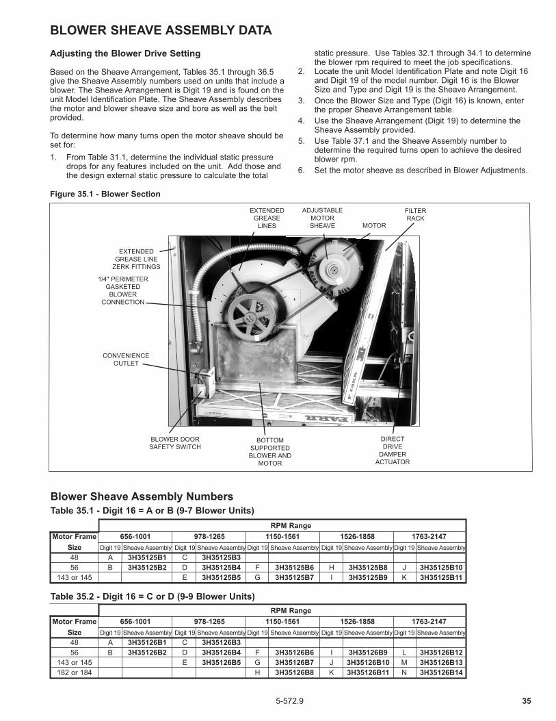
355-572.9
Table 35.1 - Digit 16 = A or B (9-7 Blower Units) RPM Range Motor Frame 656-1001 978-1265 1150-1561 1526-1858 1763-2147 Size Digit 19 Sheave Assembly Digit 19 Sheave Assembly Digit 19 Sheave Assembly Digit 19 Sheave Assembly Digit 19 Sheave Assembly 48 A 3H35125B1 C 3H35125B3 56 B 3H35125B2 D 3H35125B4 F 3H35125B6 H 3H35125B8 J 3H35125B10 143 or 145 E 3H35125B5 G 3H35125B7 I 3H35125B9 K 3H35125B11
Table 35.2 - Digit 16 = C or D (9-9 Blower Units)
Blower Sheave Assembly Numbers
RPM Range Motor Frame 656-1001 978-1265 1150-1561 1526-1858 1763-2147 Size Digit 19 Sheave Assembly Digit 19 Sheave Assembly Digit 19 Sheave Assembly Digit 19 Sheave Assembly Digit 19 Sheave Assembly 48 A 3H35126B1 C 3H35126B3 56 B 3H35126B2 D 3H35126B4 F 3H35126B6 I 3H35126B9 L 3H35126B12 143 or 145 E 3H35126B5 G 3H35126B7 J 3H35126B10 M 3H35126B13 182 or 184 H 3H35126B8 K 3H35126B11 N 3H35126B14
BLOWER SHEAVE ASSEMBLY DATAAdjusting the Blower Drive Setting
Based on the Sheave Arrangement, Tables 35.1 through 36.5 give the Sheave Assembly numbers used on units that include a blower. The Sheave Arrangement is Digit 19 and is found on the unit Model Identification Plate. The Sheave Assembly describes the motor and blower sheave size and bore as well as the belt provided.
To determine how many turns open the motor sheave should be set for: 1. From Table 31.1, determine the individual static pressure
drops for any features included on the unit. Add those and the design external static pressure to calculate the total
static pressure. Use Tables 32.1 through 34.1 to determine the blower rpm required to meet the job specifications.
2. Locate the unit Model Identification Plate and note Digit 16 and Digit 19 of the model number. Digit 16 is the Blower Size and Type and Digit 19 is the Sheave Arrangement.3. Once the Blower Size and Type (Digit 16) is known, enter the proper Sheave Arrangement table.4. Use the Sheave Arrangement (Digit 19) to determine the Sheave Assembly provided.5. Use Table 37.1 and the Sheave Assembly number to
determine the required turns open to achieve the desired blower rpm.
6. Set the motor sheave as described in Blower Adjustments.
Figure 35.1 - Blower Section
EXTENDED GREASE LINE
ZERK FITTINGS
1/4" PERIMETER GASKETED BLOWER
CONNECTION
CONVENIENCE OUTLET
BLOWER DOOR SAFETY SWITCH
BOTTOM SUPPORTED BLOWER AND
MOTOR
DIRECT DRIVE
DAMPER ACTUATOR
FILTER RACK
MOTOR
ADJUSTABLE MOTOR SHEAVE
EXTENDED GREASE
LINES

36 5-572.9
BLOWER SHEAVE ASSEMBLY DATA
Table 36.2 - Digit 16 = G or H (15-15 Blower Units)
Table 36.3 - Digit 16 = I or J (18-18 Blower Units under 15 Hp motor)
Table 36.1 - Digit 16 = E or F (12-12 Blower Units)
RPM Range Motor Frame 491-649 586-744 682-821 821-1009 995-1161 1101-1285 Size Digit 19 Sheave Assembly Digit 19 Sheave Assembly Digit 19 Sheave Assembly Digit 19 Sheave Assembly Digit 19 Sheave Assembly Digit 19 Sheave Assembly 56 A 3H35129B1 D 3H35129B4 143 or 145 B 3H35129B2 E 3H35129B5 H 3H35129B8 182 to 184 C 3H35129B3 F 3H35129B6 I 3H35129B9 K 3H35129B11 O 3H35129B15 213 or 215 G 3H35129B7 J 3H35129B10 L 3H35129B12 P 3H35129B16 S 3H35129B19 254 M 3H35129B13 Q 3H35129B17 T 3H35129B20 256 N 3H35129B14 R 3H35129B18 U 3H35129B21
RPM Range Motor Frame 468-715 644-874 863-1078 1029-1332 1150-1438 1327-1659 Size Digit 19 Sheave Assembly Digit 19 Sheave Assembly Digit 19 Sheave Assembly Digit 19 Sheave Assembly Digit 19 Sheave Assembly Digit 19 Sheave Assembly 48 A 3H35127B1 56 B 3H35127B2 C 3H35127B3 F 3H35127B6 Q 3H35127B17 143 to 145 D 3H35127B4 G 3H35127B7 I 3H35127B9 L 3H35127B12 182 or 184 E 3H35127B5 H 3H35127B8 J 3H35127B10 M 3H35127B13 O 3H35127B15 213 or 215 K 3H35127B11 N 3H35127B14 P 3H35127B16
RPM Range Motor Frame 410-625 568-771 767-958 934-1136 1136-1380 Size Digit 19 Sheave Assembly Digit 19 Sheave Assembly Digit 19 Sheave Assembly Digit 19 Sheave Assembly Digit 19 Sheave Assembly 48 A 3H35128B1 56 B 3H35128B2 D 3H35128B4 G 3H35128B7 O 3H35128B15 143 to 145 C 3H35128B3 E 3H35128B5 H 3H35128B8 J 3H35128B10 182 or 184 F 3H35128B6 I 3H35128B9 K 3H35128B11 M 3H35128B13 213 or 215 L 3H35128B12 N 3H35128B14
Table 36.4 – Digit 16 = K (18-18 Blower Units with 15 Hp motor & up)
Table 36.5 - Digit 16 = L (20-18 Blower Units)
RPM Range Motor Frame 826-1009 995-1161 1101-1285 1232-1438 Size Digit 19 Sheave Assembly Digit 19 Sheave Assembly Digit 19 Sheave Assembly Digit 19 Sheave Assembly
254 A 3H35130B1 C 3H35130B3 E 3H35130B5 256 B 3H35130B2 D 3H35130B4 F 3H35130B6 284 G 3H35130B13 I 3H35130B15 K 3H35130B17 M 3H35130B19 286 H 3H35130B14 J 3H35130B16 L 3H35130B18 N 3H35130B20
RPM Range Motor Frame 491-649 626-765 765-901 901-1059 995-1161 1101-1285 Size Digit 19 Sheave Assembly Digit 19 Sheave Assembly Digit 19 Sheave Assembly Digit 19 Sheave Assembly Digit 19 Sheave Assembly Digit 19 Sheave Assembly 143 or 145 A 3H36622B1 C 3H36622B3 182 to 184 B 3H36622B2 D 3H36622B4 F 3H36622B6 L 3H36622B12 213 or 215 E 3H36622B5 G 3H36622B7 M 3H36622B13 R 3H36622B18 254 H 3H36622B8 N 3H36622B14 S 3H36622B19 W 3H36622B23 256 I 3H36622B9 O 3H36622B15 T 3H36622B20 X 3H36622B24 284 J 3H36622B10 P 3H36622B16 U 3H36622B21 Y 3H36622B25 286 K 3H36622B11 Q 3H36622B17 V 3H36622B22 Z 3H36622B26
Blower Sheave Assembly Numbers (Con’t)

375-572.9
BLOWER SHEAVE ASSEMBLY DATA
Table 37.1 - Blower Sheave Assembly Settings
Sheave AssemblyTurns Open
0 0.5 1 1.5 2 2.5 3 3.5 4 4.5 5Blower RPM
3H35125B1-2 1001 966 932 897 863 828 794 759 725 690 656
3H35125B3-5 1265 1236 1208 1179 1150 1121 1093 1064 1035 1006 978
3H35125B6-7 1561 1520 1479 1438 1396 1355 1314 1273 1232 1191 1150
3H35125B8-9 1858 1825 1791 1758 1725 1692 1659 1625 1592 1559 1526
3H35125B10-11 2147 2108 2070 2032 1993 1955 1917 1878 1840 1802 1763
3H35126B1-2 1001 966 932 897 863 828 794 759 725 690 656
3H35126B3-5 1265 1236 1208 1179 1150 1121 1093 1064 1035 1006 978
3H35126B6-8 1561 1520 1479 1438 1396 1355 1314 1273 1232 1191 1150
3H35126B9-11 1858 1825 1791 1758 1725 1692 1659 1625 1592 1559 1526
3H35126B12-14 2147 2108 2070 2032 1993 1955 1917 1878 1840 1802 1763
3H35127B1-2 715 690 665 641 616 591 567 542 518 493 468
3H35127B3-5 874 851 828 805 782 759 736 713 690 667 644
3H35127B6-8 1078 1057 1035 1013 992 970 949 927 906 884 863
3H35127B9-11 1332 1301 1271 1241 1211 1180 1150 1120 1089 1059 1029
3H35127B12-14 1438 1409 1380 1351 1323 1294 1265 1236 1208 1179 1150
3H35127B15-16 1659 1625 1592 1559 1526 1493 1460 1426 1393 1360 1327
3H35127B17 1332 1301 1271 1241 1211 1180 1150 1120 1089 1059 1029
3H35128B1-3 625 604 582 561 539 518 496 474 453 431 410
3H35128B4-6 771 751 731 710 690 670 649 629 609 589 568
3H35128B7-9 958 939 920 901 882 863 843 824 805 786 767
3H35128B10-12 1136 1116 1096 1076 1055 1035 1015 994 974 954 934
3H35128B13-14 1380 1355 1331 1306 1281 1257 1232 1208 1183 1158 1136
3H35128B15 1136 1116 1096 1076 1055 1035 1015 994 974 954 934
3H35129B1-3 649 633 617 601 586 570 554 538 522 506 491
3H35129B4-7 744 728 712 696 681 665 649 633 617 601 586
3H35129B8-10 821 807 793 779 765 751 737 723 709 696 682
3H35129B11-14 1009 991 973 954 936 918 899 881 863 844 821
3H35129B15-18 1161 1144 1128 1111 1095 1078 1062 1045 1028 1012 995
3H35129B19-21 1285 1266 1248 1230 1211 1193 1174 1156 1138 1119 1101
3H35130B1-2 1009 991 973 954 936 918 899 881 863 844 826
3H35130B3-4 1161 1144 1128 1111 1095 1078 1062 1045 1028 1012 995
3H35130B5-6 1285 1266 1248 1230 1211 1193 1174 1156 1138 1119 1101
3H35130B13-14 974 960 946 932 918 904 890 876 863 849 835
3H35130B15-16 1161 1144 1128 1111 1095 1078 1062 1045 1028 1012 995
3H35130B17-18 1285 1266 1248 1230 1211 1193 1174 1156 1138 1119 1101
3H35130B19-20 1438 1417 1396 1376 1355 1335 1314 1294 1273 1253 1232
3H36622B1-2 649 633 617 601 586 570 554 538 522 506 491
3H36622B3-5 765 751 737 723 709 696 682 668 654 640 626
3H36622B6-11 901 888 875 863 850 837 824 811 798 785 765
3H36622B12-17 1059 1044 1029 1014 999 984 968 953 938 923 901
3H36622B18-22 1161 1144 1128 1111 1095 1078 1062 1045 1028 1012 995
3H36622B23-26 1285 1266 1248 1230 1211 1193 1174 1156 1138 1119 1101

38 5-572.9
BLOWER SHEAVE ASSEMBLY DATATable 38.1 - Blower Sheave Assembly Components
Sheave AssemblyBrowning
Belt #
Motor Sheave Blower Sheave
Prefix Suffix Pitch Dia (in.) Bore (in.) Pitch Dia
(in.)Bore (in.)
3H35125
1 A30 2.9 0.55
0.75
2 A31 2.9 0.6253 A34 4.4 0.5
64 A35 4.4 0.6255 A35 4.4 0.8756 A31 3.8 0.625
4.27 A31 3.8 0.8758 A35 5.6 0.625
5.29 A35 5.6 0.875
10 A34 5.6 0.6254.5
11 A34 5.6 0.875
3H35126
1 A33 2.9 0.55
0.75
2 A34 2.9 0.6253 A37 4.4 0.5
64 A38 4.4 0.6255 A38 4.4 0.8756 A34 3.8 0.625
4.27 A34 3.8 0.8758 A36 3.8 1.1259 A38 5.6 0.625
5.210 A38 5.6 0.87511 A40 5.6 1.12512 A37 5.6 0.625
4.513 A37 5.6 0.87514 A39 5.6 1.125
3H35127
1 A42 2.9 0.57
1
2 A43 2.9 0.6253 A46 3.8 0.625
7.54 A45 3.8 0.8755 A47 3.8 1.1256 A48 5 0.625
87 A48 5 0.8758 A50 5 1.1259 A43 4.4 0.875
5.710 A45 4.4 1.12511 A49 5.2 1.375 6.712 A45 5 0.875 613 A47 5 1.125 614 A49 5.2 1.375 6.215 A45 5 1.125 5.216 A48 5.6 1.375
5.717 A43 4.4 0.625
3H35128
1 A47 2.9 0.58
1
2 A48 2.9 0.6253 A48 2.9 0.8754 A50 3.8 0.625
8.55 A50 3.8 0.8756 A52 3.8 1.1257 A53 5 0.625
98 A52 5 0.8759 A54 5 1.125
10 A53 5.6 0.8758.5
11 A54 5.6 1.12512 A54 5.2 1.375 813 A52 5.6 1.125 714 A52 5.2 1.375 6.515 A53 5.6 0.625 8.5
Sheave AssemblyBrowning
Belt #
Motor Sheave Blower Sheave
Prefix Suffix Pitch Dia (in.) Bore (in.) Pitch Dia
(in.)Bore (in.)
3H35129
1 B71 4.1 0.625
10.9
1
2 B71 4.1 0.8753 B70 4.1 1.1254 BX71 4.7 0.6255 BX71 4.7 0.8756 BX71 4.7 1.1257 BX71 5.5 1.375
12.48 BX77 5.9 0.8759 BX75 5.9 1.125
10 BX75 5.9 1.37511 BX68 5.3 1.125 8.912 BX68 5.5 1.375
9.413 BX75 5.5 1.62514 BX75 5.5 1.62515 B73 7 1.125
10.416 B72 7 1.37517 B78 7 1.62518 B78 7 1.62519 B70 7 1.375
9.420 B77 7 1.62521 B77 7 1.625
3H35130
1 Qty (2) B74 5.5 1.6259.4
1.44
2 Qty (2) B74 5.5 1.6253 Qty (2) B78 7 1.625
10.44 Qty (2) B78 7 1.6255 Qty (2) B77 7 1.625
9.46 Qty (2) B77 7 1.625
13 Qty (2) B82 7 1.87512.4
14 Qty (2) B82 7 1.87515 Qty (2) B79 7 1.875
10.416 Qty (2) B79 7 1.87517 Qty (2) B77 7 1.875
9.418 Qty (2) B77 7 1.87519 Qty (2) B75 7 1.875
8.420 Qty (2) B75 7 1.875
3H36622
1 B75 4.1 0.87510.9
1.44
2 BX73 4.1 1.1253 B72 4.1 0.875
8.94 B70 4.1 1.1255 BX78 5.5 1.375 12.46 B74 4.7 1.125 8.97 BX75 5.5 1.375 10.48 Qty (2) BX82 6 1.625
11.49 Qty (2) BX82 6 1.625
10 Qty (2) B86 7 1.87513.4
11 Qty (2) B86 7 1.87512 B71 5.3 1.125 8.413 BX74 5.9 1.375
9.414 Qty (2) BX79 6 1.62515 Qty (2) BX79 6 1.62516 Qty (2) B83 7 1.875
11.417 Qty (2) B83 7 1.87518 B77 7 1.375
10.419 Qty (2) B82 7 1.62520 Qty (2) B82 7 1.62521 Qty (2) B81 7 1.87522 Qty (2) B81 7 1.87523 Qty (2) B80 7 1.625
9.424 Qty (2) B80 7 1.62525 Qty (2) B80 7 1.87526 Qty (2) B80 7 1.875

395-572.9
THIS PAGE INTENTIONALLY LEFT BLANK
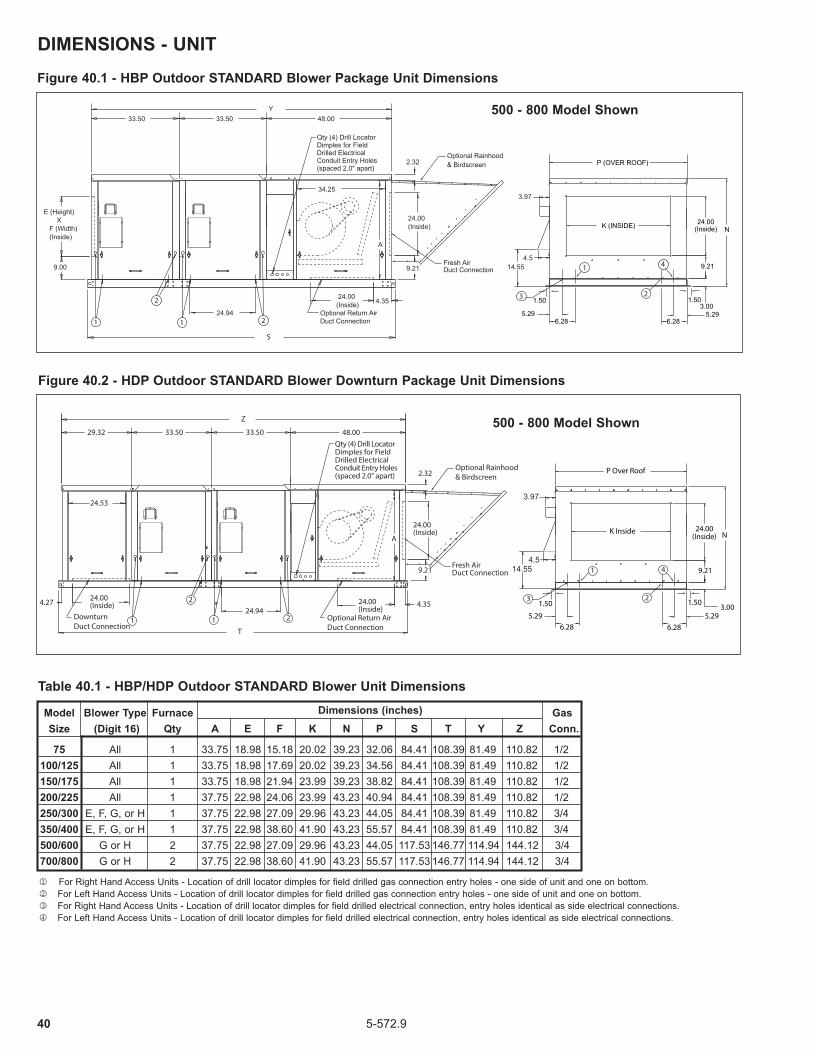
40 5-572.9
DIMENSIONS - UNITFigure 40.1 - HBP Outdoor STANDARD Blower Package Unit Dimensions
Figure 40.2 - HDP Outdoor STANDARD Blower Downturn Package Unit Dimensions
Model Blower Type Furnace Gas Size (Digit 16) Qty A E F K N P S T Y Z Conn.
75 All 1 33.75 18.98 15.18 20.02 39.23 32.06 84.41 108.39 81.49 110.82 1/2 100/125 All 1 33.75 18.98 17.69 20.02 39.23 34.56 84.41 108.39 81.49 110.82 1/2 150/175 All 1 33.75 18.98 21.94 23.99 39.23 38.82 84.41 108.39 81.49 110.82 1/2 200/225 All 1 37.75 22.98 24.06 23.99 43.23 40.94 84.41 108.39 81.49 110.82 1/2 250/300 E, F, G, or H 1 37.75 22.98 27.09 29.96 43.23 44.05 84.41 108.39 81.49 110.82 3/4 350/400 E, F, G, or H 1 37.75 22.98 38.60 41.90 43.23 55.57 84.41 108.39 81.49 110.82 3/4 500/600 G or H 2 37.75 22.98 27.09 29.96 43.23 44.05 117.53 146.77 114.94 144.12 3/4 700/800 G or H 2 37.75 22.98 38.60 41.90 43.23 55.57 117.53 146.77 114.94 144.12 3/4
j For Right Hand Access Units - Location of drill locator dimples for field drilled gas connection entry holes - one side of unit and one on bottom.k For Left Hand Access Units - Location of drill locator dimples for field drilled gas connection entry holes - one side of unit and one on bottom.l For Right Hand Access Units - Location of drill locator dimples for field drilled electrical connection, entry holes identical as side electrical connections.m For Left Hand Access Units - Location of drill locator dimples for field drilled electrical connection, entry holes identical as side electrical connections.
Table 40.1 - HBP/HDP Outdoor STANDARD Blower Unit DimensionsDimensions (inches)
5.295.29
K (INSIDE)
P (OVER ROOF)
N
9.21
3.00
24.00(Inside)
1.501.50
6.28 6.281 1
2
2
Optional Rainhood& Birdscreen
Fresh AirDuct Connection
Optional Return AirDuct Connection
9.00
E (Height) X F (Width) (Inside)
48.0033.50
24.94
Qty (4) Drill LocatorDimples for Field Drilled Electrical Conduit Entry Holes (spaced 2.0" apart)
34.25
2.32
9.21
24.00(Inside)
33.50
24.00(Inside)
A
4.35
S
Y
1
23
4
3.97
4.514.55
500 - 800 Model Shown
500 - 800 Model Shown
5.295.29
K Inside
P Over Roof
N
9.21
3.00
24.00(Inside)
1.501.50
6.28 6.28
Fresh AirDuct Connection
Optional Rainhood& Birdscreen
21
2
1 Optional Return AirDuct Connection
48.00
24.00(Inside)
9.21
2.32
24.00(Inside)
A
24.00(Inside)4.27
24.94
29.32 33.50 33.50
24.53
4.35
T
Z
1
2
4
3
Qty (4) Drill LocatorDimples for Field Drilled Electrical Conduit Entry Holes (spaced 2.0" apart)
3.97
4.514.55
DownturnDuct Connection
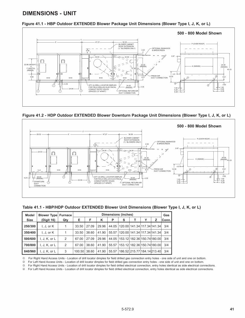
415-572.9
Figure 41.1 - HBP Outdoor EXTENDED Blower Package Unit Dimensions (Blower Type I, J, K, or L)
FRESH AIRDUCT CONNECTION
OPTIONAL RAINHOOD& BIRDSCREEN
OPTIONAL RETURN AIRDUCT CONNECTION
2
2
11
3
1
2
4
E
6.56
Y
K (INSIDE)
P (OVER ROOF)
43.23
24.00(INSIDE)
9.21
3.001.505.296.28
1.505.296.28
24.00(INSIDE)
9.21
2.32
36.58
4.3524.00
(INSIDE)
34.0034.00
37.85
4.29
24.94
47.27
S
22.98 (HEIGHT) X
F (WIDTH) (INSIDE)
9.00
QTY (4) DRILL LOCATOR DIMPLESFOR FIELD DRILLED ELECTRICAL CONDUIT ENTRY HOLES (SPACED 2.0" APART)
3.97
4.514.55
BLOWER CABINET ROOF EXTENSION(”L” BLOWERS ONLY)
2
1
3
21
2
1
4
E
6.56
K (INSIDE)
P (OVER ROOF)
43.23 24.00
(INSIDE)
9.21
3.001.505.296.28
1.505.296.28
24.00(INSIDE)
9.21
2.32
36.58
4.3524.00(INSIDE)
34.0034.00
37.85
24.00(INSIDE)4.27
24.94
T
29.32 47.27
Z
24.53
3.97
4.514.55
QTY (4) DRILL LOCATOR DIMPLESFOR FIELD DRILLED ELECTRICAL CONDUIT ENTRY HOLES (SPACED 2.0" APART)
OPTIONAL RAINHOOD& BIRDSCREEN
BLOWER CABINET ROOF EXTENSION(”L” BLOWERS ONLY)
FRESH AIRDUCT CONNECTION
OPTIONAL RETURN AIRDUCT CONNECTION
DOWNTURNDUCTCONNECTION
Figure 41.2 - HDP Outdoor EXTENDED Blower Downturn Package Unit Dimensions (Blower Type I, J, K, or L)
Model Blower Type Furnace Gas Size (Digit 16) Qty E F K P S T Y Z Conn.
250/300 I, J, or K 1 33.50 27.09 29.96 44.05 120.00 141.34 117.34 141.34 3/4
350/400 I, J, or K 1 33.50 38.60 41.90 55.57 120.00 141.34 117.34 141.34 3/4
500/600 I, J, K, or L 2 67.00 27.09 29.96 44.05 153.12 182.36 150.74 180.00 3/4
700/800 I, J, K, or L 2 67.00 38.60 41.90 55.57 153.12 182.36 150.74 180.00 3/4
840/960 I, J, K, or L 3 100.50 38.60 41.90 55.57 186.52 215.77 184.14 213.40 3/4
j For Right Hand Access Units - Location of drill locator dimples for field drilled gas connection entry holes - one side of unit and one on bottom.k For Left Hand Access Units - Location of drill locator dimples for field drilled gas connection entry holes - one side of unit and one on bottom.l For Right Hand Access Units - Location of drill locator dimples for field drilled electrical connection, entry holes identical as side electrical connections.m For Left Hand Access Units - Location of drill locator dimples for field drilled electrical connection, entry holes identical as side electrical connections.
Table 41.1 - HBP/HDP Outdoor EXTENDED Blower Unit Dimensions (Blower Type I, J, K, or L)
Dimensions (inches)
DIMENSIONS - UNIT
500 - 800 Model Shown
500 - 800 Model Shown

42 5-572.9
DIMENSIONS - UNITFigure 42.1 - HCP Outdoor STANDARD BLOWER Cooling Package Unit Dimensions
24.94
34.25
108.39
48.00105.49
J (HEIGHT)X
H (WIDTH)(INSIDE)
7.65
19.23
G
24.00 33.50
4.3524.00
(INSIDE)
A
2.20
24.00(INSIDE)
9.21
5.295.29
K (INSIDE)
P (OVER ROOF)
N
9.21
3.00
24.00(INSIDE)
1.501.50
6.28 6.28
3.97
4.514.55
2
1
3
4
OPTIONAL RETURN AIRDUCT CONNECTION
QTY (4) DRILL LOCATOR DIMPLESFOR FIELD DRILLED ELECTRICAL CONDUIT ENTRY HOLES (SPACED 2.0" APART)
FRESH AIRDUCT CONNECTION2 2
OPTIONAL RAINHOOD& BIRDSCREEN
24.944.29
137.63
34.25
48.00
134.82
24.53
24.00(INSIDE)4.27
29.32 24.00
G
19.23
24.00(INSIDE) 4.35
A
24.00(INSIDE)
9.21
2.20
33.50
5.295.29
K (INSIDE)
P (OVER ROOF)
N
9.21
3.00
24.00(INSIDE)
1.501.50
6.28 6.28
3.97
4.514.55
2
1
3
4FRESH AIRDUCT CONNECTION
OPTIONAL RAINHOOD& BIRDSCREEN
QTY (4) DRILL LOCATOR DIMPLESFOR FIELD DRILLED ELECTRICAL CONDUIT ENTRY HOLES (SPACED 2.0" APART)
OPTIONAL RETURN AIRDUCT CONNECTION
2 2
DOWNTURNDUCT CONNECTION
Figure 42.2 - HPP Outdoor STANDARD BLOWER Cooling & Downturn Packaged Unit Dimensions
Model Blower Type Gas Size (Digit 16) A G H J K N P Conn.
75 All 33.75 28.75 18.00 25.00 20.02 39.23 32.06 1/2
100/125 All 33.75 28.75 21.00 25.00 20.02 39.23 34.56 1/2
150/175 All 33.75 28.75 24.00 25.00 23.99 39.23 38.82 1/2
200/225 All 37.75 32.75 27.00 28.00 23.99 43.23 40.94 1/2
250/300 E, F, G, or H 37.75 32.75 30.00 28.00 29.96 43.23 44.05 3/4
350/400 E, F, G, or H 37.75 32.75 42.00 28.00 41.90 43.23 55.57 3/4
j For Right Hand Access Units - Location of drill locator dimples for field drilled gas connection entry holes - one side of unit and one on bottom.k For Left Hand Access Units - Location of drill locator dimples for field drilled gas connection entry holes - one side of unit and one on bottom.l For Right Hand Access Units - Location of drill locator dimples for field drilled electrical connection, entry holes identical as side electrical connections.m For Left Hand Access Units - Location of drill locator dimples for field drilled electrical connection, entry holes identical as side electrical connections.
Dimensions (inches)
Table 43.1 - HCP/HPP Outdoor STANDARD Blower Unit Dimensions
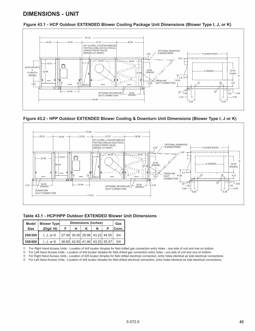
435-572.9
Figure 43.1 - HCP Outdoor EXTENDED Blower Cooling Package Unit Dimensions (Blower Type I, J, or K)
24.94
143.98
24.00
141.34
7.65
32.68
19.23
37.85
33.50 47.27 36.58
24.00(INSIDE)
34.0034.00
24.00(INSIDE)
9.21
5.295.29
K (INSIDE)
P (OVER ROOF)
N
9.21
3.00
24.00(Inside)
1.501.50
6.28 6.28
3.97
4.514.55
QTY (4) DRILL LOCATOR DIMPLESFOR FIELD DRILLED ELECTRICAL CONDUIT ENTRY HOLES (SPACED 2.0" APART)
OPTIONAL RETURN AIRDUCT CONNECTION
OPTIONAL RAINHOOD& BIRDSCREEN
FRESH AIRDUCT CONNECTION2 2 1 4
23
2.32
28.00 (HEIGHT)X
H (WIDTH)(INSIDE)
24.944.27 24.00(INSIDE)
24.53
29.32
173.22
170.66
37.85
19.23
32.68
24.00
34.00 34.00
24.00(INSIDE)
4.35
36.5847.2733.50
2.32
9.21
24.00(INSIDE)
5.295.29
K (INSIDE)
P (OVER ROOF)
N
9.21
3.00
24.00(INSIDE)
1.501.50
6.28 6.28
3.97
4.514.55
DOWNTURNDUCT CONNECTION
QTY (4) DRILL LOCATOR DIMPLESFOR FIELD DRILLED ELECTRICAL CONDUIT ENTRY HOLES (SPACED 2.0" APART)
OPTIONAL RETURN AIRDUCT CONNECTION
OPTIONAL RAINHOOD& BIRDSCREEN
FRESH AIRDUCTCONNECTION
2 2 1 4
23
Figure 43.2 - HPP Outdoor EXTENDED Blower Cooling & Downturn Unit Dimensions (Blower Type I, J or K)
Model Blower Type Gas Size (Digit 16) F H K N P Conn.
250/300 I, J, or K 27.09 30.00 29.96 43.23 44.05 3/4
350/400 I, J, or K 38.60 42.00 41.90 43.23 55.57 3/4
j For Right Hand Access Units - Location of drill locator dimples for field drilled gas connection entry holes - one side of unit and one on bottom.k For Left Hand Access Units - Location of drill locator dimples for field drilled gas connection entry holes - one side of unit and one on bottom.l For Right Hand Access Units - Location of drill locator dimples for field drilled electrical connection, entry holes identical as side electrical connections.m For Left Hand Access Units - Location of drill locator dimples for field drilled electrical connection, entry holes identical as side electrical connections.
Dimensions (inches)
Table 43.1 - HCP/HPP Outdoor EXTENDED Blower Unit Dimensions
DIMENSIONS - UNIT

44 5-572.9
THIS PAGE INTENTIONALLY LEFT BLANK
DIMENSIONS - UNIT

455-572.9
DIMENSIONS - UNIT BASE
Return Air OpeningSupply Air Opening
6.28
6.28
To end of UnitAC
FG
H
M
E
M
M
E
M
Inside 4.3524.00Inside24.004.29
JB
InsideInside
Drill Locator Dimple for Field Drilled Gas Connection Entry HoleLeft Hand Access Units
Drill Locator Dimple for Field Drilled Gas Connection Entry Hole Right Hand Access Units
Figure 45.1 - Unit Base Dimensions
Table 45.1 - HBP & HDP Outdoor Unit Base Rail Dimensions (All dimensions in inches)
Dimensions Model Blower Type HBP HDP HBP/HDP Size (Digit 16) A C A C B E F j G j H J M
75 All 84.41 81.49 113.63 110.82 34.85 19.52 78.66 53.72 1.53 32.00 6.23 100/125 All 84.41 81.49 113.63 110.82 37.36 19.52 78.66 53.72 1.53 34.50 7.49 150/175 All 84.41 81.49 113.63 110.82 41.61 23.49 78.66 53.72 1.53 38.75 7.63 200/225 All 84.41 81.49 113.63 110.82 43.71 23.49 78.66 53.72 1.53 40.85 8.69 250/300 E,F,G, or H 84.41 81.49 113.63 110.82 46.75 29.46 78.66 53.72 1.53 43.89 7.21 250/300 I, J, or K 120.00 117.34 149.22 146.66 46.75 29.46 114.23 84.29 1.28 43.89 7.21 350/400 E,F,G, or H 84.41 81.49 113.63 110.82 58.27 41.40 78.66 53.72 1.53 55.41 7.00 350/400 I, J, or K 120.00 117.34 149.22 146.66 58.27 41.40 114.23 82.29 1.28 55.41 7.00 500/600 G or H 117.53 114.94 146.77 144.12 46.75 29.46 78.66 53.72 1.53 43.89 7.21 500/600 I, J, K, or L 153.12 150.74 182.36 180.00 46.75 29.46 114.23 82.29 1.28 43.89 7.21 700/800 G or H 117.53 114.94 146.77 144.12 58.27 41.40 78.66 53.72 1.53 55.41 7.00 700/800 I, J, K, or L 153.12 150.74 182.36 180.00 58.27 41.40 114.23 82.29 1.28 55.41 7.00 840/960 I, J, K, or L 186.52 184.14 215.77 213.40 58.27 41.40 114.23 82.29 1.28 55.41 7.00
Table 45.2 - HCP & HPP Outdoor Unit Base Rail Dimensions (All dimensions in inches)
Dimensions Model Blower Type HCP HPP HCP/HPP Size (Digit 16) A C A C B E F G H J M
75 All 108.39 105.49 137.63 134.82 34.85 19.52 78.66 53.72 1.53 32.00 6.23 100/125 All 108.39 105.49 137.63 134.82 37.36 19.52 78.66 53.72 1.53 34.50 7.49 150/175 All 108.39 105.49 137.63 134.82 41.61 23.49 78.66 53.72 1.53 38.75 7.63 200/225 All 108.39 105.49 137.63 134.82 43.71 23.49 78.66 53.72 1.53 40.85 8.69 250/300 E,F,G, or H 108.39 105.49 137.63 134.82 46.75 29.46 78.66 53.72 1.53 43.89 7.21 250/300 I, J, or K 143.98 141.34 173.22 170.66 46.75 29.46 114.23 82.29 1.28 43.89 7.21 350/400 E,F,G, or H 108.39 105.49 137.63 134.82 58.27 41.40 78.66 53.72 1.53 55.41 7.00 350/400 I, J, or K 143.98 141.34 173.22 170.66 58.27 41.40 114.23 82.29 1.28 55.41 7.00
j Gas connection for 1st furnace. For Models 500-800 add 33.5” for second furnace gas connection. For Model 840-960 add 33.50” and 67.00” for second and third furnace gas connections.
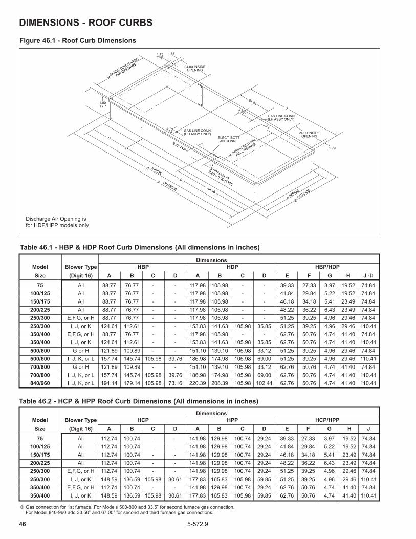
46 5-572.9
DIMENSIONS - ROOF CURBS
Figure 46.1 - Roof Curb Dimensions
Discharge Air Opening isfor HDP/HPP models only
Table 46.1 - HBP & HDP Roof Curb Dimensions (All dimensions in inches)
Table 46.2 - HCP & HPP Roof Curb Dimensions (All dimensions in inches) Dimensions Model Blower Type HCP HPP HCP/HPP Size (Digit 16) A B C D A B C D E F G H J
75 All 112.74 100.74 - - 141.98 129.98 100.74 29.24 39.33 27.33 3.97 19.52 74.84 100/125 All 112.74 100.74 - - 141.98 129.98 100.74 29.24 41.84 29.84 5.22 19.52 74.84 150/175 All 112.74 100.74 - - 141.98 129.98 100.74 29.24 46.18 34.18 5.41 23.49 74.84 200/225 All 112.74 100.74 - - 141.98 129.98 100.74 29.24 48.22 36.22 6.43 23.49 74.84 250/300 E,F,G, or H 112.74 100.74 - - 141.98 129.98 100.74 29.24 51.25 39.25 4.96 29.46 74.84 250/300 I, J, or K 148.59 136.59 105.98 30.61 177.83 165.83 105.98 59.85 51.25 39.25 4.96 29.46 110.41 350/400 E,F,G, or H 112.74 100.74 - - 141.98 129.98 100.74 29.24 62.76 50.76 4.74 41.40 74.84 350/400 I, J, or K 148.59 136.59 105.98 30.61 177.83 165.83 105.98 59.85 62.76 50.76 4.74 41.40 110.41
Dimensions Model Blower Type HBP HDP HBP/HDP Size (Digit 16) A B C D A B C D E F G H J j
75 All 88.77 76.77 - - 117.98 105.98 - - 39.33 27.33 3.97 19.52 74.84 100/125 All 88.77 76.77 - - 117.98 105.98 - - 41.84 29.84 5.22 19.52 74.84 150/175 All 88.77 76.77 - - 117.98 105.98 - - 46.18 34.18 5.41 23.49 74.84 200/225 All 88.77 76.77 - - 117.98 105.98 - - 48.22 36.22 6.43 23.49 74.84 250/300 E,F,G, or H 88.77 76.77 - - 117.98 105.98 - - 51.25 39.25 4.96 29.46 74.84 250/300 I, J, or K 124.61 112.61 - - 153.83 141.63 105.98 35.85 51.25 39.25 4.96 29.46 110.41 350/400 E,F,G, or H 88.77 76.77 - - 117.98 105.98 - - 62.76 50.76 4.74 41.40 74.84 350/400 I, J, or K 124.61 112.61 - - 153.83 141.63 105.98 35.85 62.76 50.76 4.74 41.40 110.41 500/600 G or H 121.89 109.89 - - 151.10 139.10 105.98 33.12 51.25 39.25 4.96 29.46 74.84 500/600 I, J, K, or L 157.74 145.74 105.98 39.76 186.98 174.98 105.98 69.00 51.25 39.25 4.96 29.46 110.41 700/800 G or H 121.89 109.89 - - 151.10 139.10 105.98 33.12 62.76 50.76 4.74 41.40 74.84 700/800 I, J, K, or L 157.74 145.74 105.98 39.76 186.98 174.98 105.98 69.00 62.76 50.76 4.74 41.40 110.41 840/960 I, J, K, or L 191.14 179.14 105.98 73.16 220.39 208.39 105.98 102.41 62.76 50.76 4.74 41.40 110.41
j Gas connection for 1st furnace. For Models 500-800 add 33.5” for second furnace gas connection. For Model 840-960 add 33.50” and 67.00” for second and third furnace gas connections.

475-572.9
Model Size FH H S V FL I L Supply Line Return Line
75 27 30 1.5 1.5 16.25 25.50 19.25 1.50 MPT 1.50 MPT 100/125 27 30 1.5 1.5 19.50 28.75 22.50 1.50 MPT 1.50 MPT 150/175 27 30 1.5 1.5 23.00 32.25 26.00 1.50 MPT 1.50 MPT 200/225 33 34.5 0.5 1 25.50 34.75 28.50 1.50 MPT 1.50 MPT 250/300 33 34.5 0.5 1 28.50 37.75 31.50 1.50 MPT 1.50 MPT 350/400 33 34.5 0.5 1 40.25 49.50 43.25 1.50 MPT 1.50 MPT
Table 47.2 - Chilled Water Coil Dimensions
Figure 47.2 - Chilled Water Coil Drawing (All dimensions in inches)
Rows 2 3 4 6 W 7.5 6 7.5 10
Rows 4 6 W 7.5 10
L1.5 1.5
H
W
1.5
I
AirflowDirection
TOP VIEW
FL
FH
Airflow Direction
SCoil for Right Hand Units (Digit 9 = R)
Headers on opposite side for Left Hand Units
Suction Line Connections in direction of airflow
(Second Inlet on Dual Circuit Coils)
Distributor Inlet (Liquid Line) Connection(s)
(Second Inlet on Dual Circuit Coils)
FRONT VIEW SIDE VIEW
L1.5 1.5
H
W
V
I
AirflowDirection
TOP VIEW
FL
FH
Airflow Direction
S
1.8
1.8
2.25
2.25
Supply Water Line Connection turned 90° in
direction of airflow
Return Water Line Connection turned 90° in
direction of airflow
Coil for Right Hand Units (Digit 9 = R)
Headers on opposite side for Left Hand Units FRONT VIEW
SIDE VIEW
DIMENSIONS - COOLING COILSFigure 47.1 - DX Coil Drawing (All dimensions in inches)
All
All
Below 185 MBH
Below 185 MBH
Below 185 MBH
185 MBH & Up
185 MBH & Up
185 MBH & Up
Table 47.1 - DX Coil DimensionsHFHModel Size Cooling MBH
DX - Single Circuit j DX - Dual Circuit kS FL I L FL I L
75
100/125
150/175
200/225
250/300
350/400
All 27.5 18 16.25
19.5
23
25.5
28.5
40.25
21
24
27
27
30
30
42
42
27.5
27.5
32.5
32.5
32.5
32.5
32.5
32.5
30.5 25 26.5
29.75
33.25
35.75
38.75
50.5
28
31
34
34.5
37
37.5
49
49.5
30.5
30.5
34.5
34.5
34.5
34.5
34.5
34.5
1.5 21 19.25
22.5
28.5
28.5
31.5
43.25
24
27
30
30
33
33
45
45
1.5
1.5
0.5
0.5
0.5
0.5
0.5
0.5
j Single Circuit DX coils have 1 each Suction Line and Liquid Lines. Refer to AccuSpec for line size diameters.k Dual Circuit DX coils have 2 each Suction Line and Liquid Lines. Refer to AccuSpec for line size diameters.

48 5-572.9
Remote Panel Type A B C Light and Switch Panels Only 7.06 - 2.81 Light and Switch Panels with Single Stage Thermostat or Electronic Set Point Adjustor 10.60 3.53 4.58
Light and Switch Panels with Two Stage Thermostat 13.09 6.03 5.82
DIMENSIONS - RAINHOOD, REMOTE PANEL & EVAPORATIVE COOLER
Table 48.2 - Evap Cooler Dimension, Performance, and Weight Data
32.71
1.09
31.19
.75
1.14A1.14
44.56
42.66 Approx.
Rainhood & Birdscreen Model Size A 75 29.43 100/125 31.94 150/175 38.24 200/225 38.24 250/300 41.34 350/400 52.85 500/600 41.34 700/800 52.85 840/960 52.85
Table 48.1 - Rainhood and Birdscreen Dimensions (inches)
Figure 48.3 - Remote Panel Dimensions
C
A
B
3.53
2.56
5.57
1.50
3.53
3.382.13
NOTES:1. Holes visable on right side are also on the left side in the same location.2. Holes on top are also on the back in the same location horizontally.
Table 48.3 - Remote Panel Dimensions (inches)
Figure 48.1 - Rainhood and Birdscreen Dimensions
Figure 48.2 - Evaporative Cooling Module
J-Box
Pump
Optional 1"Pre-Filter Rack
W/2 -1.50
3.00
3.00
1.50
4.50
1.25
1.25
W
BlowerSection
Leveling Legs
6" or 12" Media
.25
4.50
25.50
36.00
H
1/2" NPT Drain
1/2" NPT Overflow
1/2" NPT Drain
1/2" NPT Overflow
1/2" NPT Water Inlet
Top View
Side View
Model SizeBlower Type
(digit 16) H (in.) W (in.)
Maximum Cooling
CFM
Media Face Area
(ft2)
Face Velocity @ Max CFM
(ft/min)
12” Media (Digit 23 = B or D)
Dry Weight (lbs) Op. Weight (lbs)75 All 34 30 2778 4.0 695 154 285
100/125 All 34 30 4000 5.0 800 159 295
150/175 All 34 36 5200 6.5 800 169 336
200/225 All 38 36 6000 7.5 800 174 341
250/300 E,F,G, or H 38 39 6500 8.1 800 182 363
250/300 I, J, or k 56 39 10400 13.0 800 214 404
350/400 E,F,G, or H 38 51 8500 10.6 800 228 473
350/400 I, J, or k 47 51 11050 13.8 800 244 496
500/600 G or H 38 39 6500 8.1 800 182 363
500/600 I, J, k or L 56 39 10400 13.0 800 214 404
700/800 G or H 38 51 8500 10.6 800 228 473
700/800 I, J, k or L 47 51 11050 13.8 800 244 496
840/960 I, J, k or L 47 51 11050 13.8 800 244 496

495-572.9
WEIGHTS
Table 49.1 - Unit Operating Weights j
Table 49.2 - Motor Operating Weights j
j All weights in pounds and are approximate.
Model Size
Blower Type (Digit 16)
Base Unit
Motor Filters
DampersRain-hood
Double Wall (all sections)Evap
CoolerHBP HDP HCP HPPFresh Air
OnlyFresh &
Return Air HBP HDP HCP HPP75 All 439 540 546 647
See
Mot
or D
ata
6 26 46 65 38 73 72 107
See
Eva
pora
tive
Coo
ler D
ata
100/125 All 474 578 584 688 6 26 46 67 38 73 72 107
150/175 All 511 621 626 736 6 29 52 70 43 78 77 112
200/225 All 588 707 714 833 6 29 52 72 46 86 85 125
250/300 E,F,G, or H 626 747 756 877 8 33 60 83 46 88 87 129
250/300 I, J, or k 875 996 1005 1126 15 33 60 83 93 135 134 176
350/400 E,F,G, or H 738 876 887 1025 12 38 70 90 53 102 101 150
350/400 I, J, or k 1019 1057 1168 1306 17 38 70 90 96 145 144 193
500/600 G or H 959 1080 n/a n/a 8 33 60 83 46 88 n/a n/a
500/600 I, J, k, or L 1208 1329 n/a n/a 15 33 60 83 93 135 n/a n/a
700/800 G or H 1153 1291 n/a n/a 12 38 70 90 53 102 n/a n/a
700/800 I, J, k, or L 1352 1490 n/a n/a 17 38 70 90 96 145 n/a n/a
840/960 I, J, k, or L 1767 1905 n/a n/a 17 38 70 90 96 145 n/a n/a
Digit 17 - Motor Size
Digit 14 - Supply Voltage
Digit 18 - Motor Type
A or L B or M C or N D or P E or Q F or R G or S H or T I or W J or X K or Y V or Z
1/3 1/2 3/4 1 1-1/2 2 3 5 7-1/2 10 15 20
A - 115/60/1ph1 - ODP 25 23 25 32 40 49 81 - - - - -
5 - TE 25 28 30 37 45 49 83 - - - - -
B - 208/60/1ph1 - ODP - 23 25 32 40 49 81 87 - - - -
5 - TE - 28 30 37 45 49 83 86 - - - -
C - 230/60/1ph1 - ODP 25 23 25 32 40 49 81 87 - - - -
5 - TE 25 28 30 37 45 49 83 86 - - - -
D - 208/60/3ph
1 - ODP 17 18 21 - - - - - - - - -
2 - ODP HE - - - 83 94 99 83 94 141 126 220 250
5 - TE 15 23 26 - - - - - - - - -
6 - TE HE - - - 68 66 66 92 99 158 200 259 368
E - 230/60/3ph
1 - ODP 17 18 21 - - - - - - - - -
2 - ODP HE - - - 40 46 54 87 94 130 126 217 250
5 - TE 15 23 30 - - - - - - - - -
6 - TE HE - - - 53 66 67 92 117 194 213 322 368
F - 460/60/3ph
1 - ODP 17 18 21 - - - - - - - - -
2 - ODP HE - - - 40 46 54 87 94 130 126 217 250
5 - TE 15 23 30 - - - - - - - - -
6 - TE HE - - - 53 66 66 92 117 194 213 322 368
G - 575/60/3ph
1 - ODP - 25 28 - - - - - - - - -
2 - ODP HE - - - 35 40 45 76 89 90 220 310 360
5 - TE - 24 33 - - - - - - - - -
6 - TE HE - - - 68 40 67 100 125 192 200 326 368

50 5-572.9
MAINTENANCE
All heating equipment should be serviced before each heating season to assure proper operations. The following items may be required to have more frequent service schedule based on the environment in which the unit is installed, and the frequency of the equipment operation.
Blower AssemblyThe blower assembly includes the bearings, drive sheaves and belts.Blower bearings should be checked and lubricated based on the blower manufacturer’s recommendations. Bearings should also be checked for any unusual wear and replaced if needed.Drive sheaves should be checked at the same time the bearings are inspected. Check to make sure the sheaves are in alignment and are securely fastened to the blower and motor shafts.Belt tension should be rechecked shortly after the unit has been installed to check for belt stretching. After the initial start-up, monthly checks are recommended.
FiltersIf the unit is supplied with a dirty filter switch and light, clean or replace the filters any time the dirty filter light comes on.Units which do not have a dirty filter warning light should have the filters checked monthly. Clean or replace if necessary. In dirty atmospheres, filter maintenance may be required more often.
Figure 50.1 - Filter Replacement Arrangement for Blower Size (Digit 16) A, B, C, D, E, F, G and H
A = 20'' x 25''B = 16'' x 25''C = 20'' x 16''D = 15'' X 25''
NON-ACCESS SIDE
FILTER SPACER
NON-ACCESS SIDE
FILTER SPACER
A A
AA
D
B
C
CC
B
A
A
A
AA
A
A
250/300 500/600
350/400 700/800 840/960
D
A = 20" X 25" FILTERB = 16" X 25" FILTERC = 15" X 25" FILTER Filter Spacer to be inserted on non-access side of unit
200/225
FILTER SPACER
FILTER SPACER
100/12575
A
AB
B
BB
BC
CB
B
AA
AA A
A
AA
A
A
A
AC
C
B
150/175
▼
350/400 700/800
250/300 500/600
IMPORTANTTo check most of the Possible Remedies in the troubleshooting guide listed in Table 52.1, refer to the applicable sections of the manual.
CAUTIONDo not attempt to reuse any mechanical or electrical controllers which have been wet. Replace defective controller.
WARNINGWhen servicing or repairing this equipment, use only factory-approved service replacement parts. A complete replacement parts list may be obtained by contacting Modine Manufacturing Company. Refer to the rating plate on the appliance for complete appliance model number, serial number, and company address. Any substitution of parts or controls not approved by the factory will be at the owner’s risk.
Cooling Coil Drain Pan and Drain SystemThe drain pan, trap, and drain pipe must be cleaned regularly to avoid blockage that can reduce or stop water flow as follows:1. At the beginning of the cooling season, inspect and clean
the entire cooling coil cabinet and condensate drain pan to remove contaminants.
2. Inspect and clean the condensate drain trap and piping. The use of a cleanout opening at the top of the trap can help facilitate this maintenance.
3. Fill the trap with water to ensure proper operation and replace the cap on the cleanout opening to close the system.
4. During the end of cooling season shutdown of the system, disconnect and remove all water from the trap and drain to prevent freeze damage. If local building codes permit, the trap may be filled with an antifreeze solution.
5. If the unit is used year round, regularly inspect and clean the cooling coil cabinet, condensate drain pan, and trap/drain system to ensure proper function.
6. Depending on climate, freeze protection of the trap may be required during non-cooling days.
Cooling Coil Maintenance1. Periodically, inspect the coil for signs of corrosion and leaks.
Repair and replacement of the coil and the connecting piping, valves, etc., must be performed as needed by a qualified technician.
2. Should the coil surface need cleaning, caution should be exercised in selecting the cleaning solution as well as the cleaning equipment. Improper selection can result in damage to the coil and/or health hazards. Cleaning solutions must not be corrosive or cause damage to copper tube/aluminum fin coils. Clean the coil from the leaving air-side so that foreign material will be washed out of the coil rather than pushed further in. Be sure to carefully read and follow the cleaning fluid manufacturer’s recommendations before using any cleaning fluid.
3. For DX coils, replace the filter dryer(s) as needed.4. For chilled fluid coils: a. Maintain the circulated fluid free of sediment, corrosive
products and biological contaminants. b. Freeze Protection - During the winter, chilled water coils
need to be protected against freezing. Two common methods are 1) blowing out the coils with air, or 2) flushing coils with inhibited glycol designed for corrosion protection in HVAC applications. Select an inhibited glycol solution that will protect the coil from the lowest possible temperatures that can occur at that locality.
Figure 50.2 - Filter Replacement Arrangement for Blower Size (Digit 16) I, J, K, and L

515-572.9
Electrical WiringThe electrical wiring should be checked annually for loose connections or deteriorated insulation.
Duct FurnaceWhen providing annual maintenance for the duct furnace, keep the unit free from dust, dirt, grease and foreign matter. Pay particular attention to:1. The power exhauster discharge opening and the
combustion air inlet louvers.2. The burner ports and pilot burner orifices (avoid the use of
hard, sharp instruments capable of damaging surfaces for cleaning these ports). To check the burner port and pilot burner orifice, see Burner and Pilot Assembly Removal.
3. The air shutters and main burner orifices (avoid the use of hard, sharp instruments capable of damaging surfaces for cleaning these orifices). To check the air shutters and main burner orifices, see for Manifold Assembly Removal.
The heat exchanger should be checked annually for cracks and discoloration of the tubes. If a crack is detected, the heat exchanger should be replaced before the unit is put back into service. If the tubes are dark gray, airflow across the heat exchanger should be checked to insure that a blockage has not occurred or the blower is operating properly.
Gas Piping & ControlsThe gas valves and piping should be checked annually for general cleanliness and tightness.The gas controls should be checked to insure that the unit is operating properly.
Manifold Assembly RemovalTo remove the manifold (Refer to Figure 51.1): 1. Shut off gas and electric supply.2. Remove the side access panel.3. Disconnect gas manifold at ground union joint.4. Remove the two screws holding the manifold to the heat
exchanger support.5. Slide the manifold through the manifold bracket.6. Clean the orifices and adjust the air shutters as necessary.7. Follow steps 3-6 in reverse to install the manifold
assembly.8. Turn on the electric and gas supply.9. Check the ground union joint for leaks with a soap solution.
Tighten if necessary.10. Install the side access panel.
BURNER SIDE ACCESS PANEL
HEAT EXCHANGER SUPPORT
MANIFOLD
GROUND UNION JOINT
ELECTRICAL JUNCTION
BOX
SERIAL PLATE
Figure 51.1 - Manifold Assembly Removal
Burner and Pilot Assembly RemovalTo remove the burner (Refer to Figure 51.2):1. Shut off gas and electric supply.2. Disconnect the pilot supply line from the gas valve.3. Disconnect the ignition cable from the ignition controller
(located in the electrical junction box). Feed the cable through the bushing in the bottom of the electrical junction box.
4. Remove the screws holding the burner side access panel.Attached to the panel are the burner retaining pins that align the burner.
5. Slide the burner assembly out. The pilot is attached to the burner assembly.
6. Examine the burner and pilot assembly for cleanliness and/or obstructions as necessary (see Duct Furnace for cleaning instructions).
7. Replace the burner assembly in reverse order. In replacing the burner, be certain that the rear burner slots are located properly on the burner retaining pins. Do not force the burner side access panel, it will not fit if the burner is not properly aligned.
8. Reconnect the ignition cable and pilot gas supply line.9. Turn on the electric and gas supply.
Figure 51.2 - Burner and Pilot Assembly Removal
PILOT SUPPLY LINE
HEAT EXCHANGER
SUPPORT
AIR SHUTTERS (NOT SHOWN) ARE LOCATED
ON THE MANIFOLD
IGNITION CABLE
PILOT ASSEMBLY

52 5-572.9
SERVICE & TROUBLESHOOTING
Pilot does not light
Main burners do not light (Pilot is lit)
Lifting Flames (See Figure 53.1)
Yellow Tipping (With propane gas, some yellow tipping
is always present.)
Flashback
Floating Flames (See Figure 53.2)
1. Main gas is off.2. Power supply is off.3. Air in gas line.4. Dirt in pilot orifice.
5. Gas pressure out of proper range.
6. Pilot valve does not open. a. Defective ignition controller. b. Defective gas valve.7. No Spark at ignitor. a. Loose wire connections. b. Pilot sensor is grounded. c. Defective ignition controller.8. Safety device has cut power.
1. Defective valve.2. Loose wiring.3. Defective pilot sensor4. Defective ignition controller.5. Improper thermostat wiring.
1. Too much primary air.2. Main pressure set too high.3. Orifice too large.
1. Insufficient primary air.2. Dirty orifice.
3. Misaligned orifice.
1. Too much primary air.2. Main pressure set too high.3. Orifice too large.
1. Insufficient primary air.2. Main pressure set too high.3. Orifice too large.
4. Blocked vent cap.
1. Open manual gas valve.2. Turn on main power.3. Purge gas line.4. Check for plugged pilot orifice and clean
with compressed air if necessary.5. Adjust to a maximum of 14" W.C. Minimum for Natural Gas - 6" W.C. Minimum for Propane Gas - 11" W.C.6. Check wiring for 24 volts to valve. a. Replace ignition controller. b. Replace gas valve.7. a. Check all ignition controller wiring. b. Replace sensor if cracked or worn c. Replace ignition controller.8. Check all safety devices (High limit, air
flow proving switch, power exhauster centrifugal switch - HFP Models Only, gas pressure switches, etc.) Determine and correct problem. Reset if necessary.
1. Replace valve.2. Check wiring to gas valve.3. Replace pilot sensor.4. Replace ignition controller.5. Verify wiring compared to wiring diagram.
1. Reduce primary air.2. Adjust to a maximum of 14" W.C.3. Check orifice size with those listed on
the serial plate.
1. Increase primary air.2. Check orifices and clean with
compressed air if necessary.3. Check manifold, replace if necessary.
1. Reduce primary air.2. Adjust to a maximum of 14" W.C.3. Check orifice size with those listed on
the serial plate.
1. Increase primary air.2. Adjust to a maximum of 14" W.C.3. Check orifice size with those listed on
the serial plate.4. Clean louvers in vent cap.
Trouble Possible Cause Possible Remedy
IMPORTANTTo check most of the Possible Remedies in the troubleshooting guide listed in Table 52.1, refer to the applicable sections of the manual.
CAUTIONDo not reuse any mechanical or electrical component which has been wet. Such component must be replaced.
WARNINGWhen servicing or repairing this equipment, use only factory-approved service replacement parts. A complete replacement parts list may be obtained by contacting Modine Manufacturing Company. Refer to the rating plate on the unit for complete unit model number, serial number, and company address. Any substitution of parts or controls not approved by the factory will be at the owner’s risk.
Table 52.1 - Troubleshooting

535-572.9
SERVICE & TROUBLESHOOTING
Flame Rollout (See Figure 53.3)
Not Enough Heat
Too Much Heat
Power Exhauster Motor will not start
1. Main pressure set too high.2. Orifice too large.
3. Blocked vent cap.
1. Unit cycling on high limit. j a. Obstructions/leaks in duct system. b. Main pressure set too high. c. Blower motor not energized.
d. Loose belt e. Blower speed too low.
f. Blocked/damaged venting system. g. Air distribution baffle removed (high
temperature rise units only). h. Defective high limit switch.2. Main pressure set too low.
3. Too much outside air.
4. Thermostat malfunction.5. Gas controls wired incorrectly.
6. Unit undersized.
1. Thermostat malfunction.2. Gas controls do not shut-off. a. Gas controls wired incorrectly.
b. Short circuit.3. Main gas pressure set too high.4. Defective gas valve.
1. Power supply is off.2. No 24V power to thermostat.3. Thermostat malfunction.4. Defective power exhauster relay.5. Defective power exhauster motor.
1. Adjust to a maximum of 14" W.C.2. Check orifice size with those listed on the serial plate.3. Clean louvers in vent cap.
1. a. Clean/correct duct system. b. Adjust to a maximum of 14" W.C. c. Check/correct to insure blower motor
operates within 45 seconds of when gas controls are energized.
d. Adjust belt tension. e. Check/correct blower drive settings for
proper rpm. f. Check/correct venting system. g. Replace air distribution baffle.
h. Replace high limit switch.2. Adjust main gas pressure. Minimum for Natural Gas — 6" W.C. Minimum for Propane Gas — 11" W.C.3. Adjust outside air damper to decrease
outside air percentage (if possible).4. Check/replace thermostat.5. Check unit wiring against the wiring
diagram.6. Check design conditions. If unit is
undersized, an additional unit(s) or other heat source must be added.
1. Check/replace thermostat.2. a. Check unit wiring against the wiring
diagram. b. Check for loose or worn wires.3. Adjust to a maximum of 14" W.C.4. Replace gas valve.
1. Turn on main power.2. Check control transformer.3. Check/replace thermostat.4. Replace power exhauster relay.5. Replace power exhauster motor.
Trouble Possible Cause Possible Remedy
Figure 53.1Lifting Flame Condition
Figure 53.2Floating Flame Condition
Figure 53.3Flame Rollout Appearance
j Automatic Reset High LimitThe duct furnace comes standard with an automatic reset high limit switch that will shut-off the gas should the discharge air temperature become excessive. See Figure 19.1, indicator for the location of either the standard automatic or optional manual reset high limit switch. The switch should operate only when something is seriously wrong with the unit operation. Anytime the switch operates, correct the difficulty immediately or serious damage may result. If the switch cuts off the gas supply during normal operation, refer to the “Not Enough Heat” section of Service & Troubleshooting.
49

54 5-572.9
Model IdentificationModine weatherproof duct furnace/make-up air units contain an ETL/ETL Canada certified weatherproof duct furnace. This duct furnace is combined with either a blower section, or a blower and/or cooling and/or downturn sections to make a complete make-up air or heating/ventilating/cooling unit that is ETL/ETL Canada certified. For this reason, two identification plates are used on these models. The Serial Plate is used to identify the duct furnace and its components. The Model Identification Plate is used to identify the complete model, including blower, cooling, and/or downturn sections.
OrderingWhen servicing, repairing or replacing parts on these units, locate the model identification plate of the unit and always give the complete Model Number and Serial Number from the model identification plate. The model identification plate is located on the door of the electrical control box (See Figure 54.1). The part number for some common replacement parts are listed on the serial plate (See Figure 54.2) and the model identification plate (See Figure 55.1). For a complete description of the model number, see Model Identification.
Figure 54.1 - Serial Plate and Model ID Plate Locations
MODEL DESIGNATIONS
Figure 54.2 - Serial Plate
MODELIDENTIFICATION PLATE
SERIAL PLATE
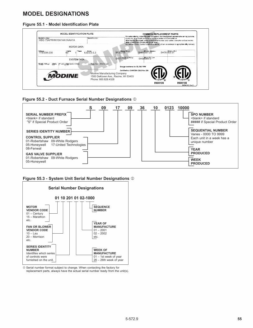
555-572.9
MODEL DESIGNATIONSFigure 55.1 - Model Identification Plate
Serial Number Designations
01 10 201 01 02-1000
MOTOR VENDOR CODE 01 – Century 15 – Marathon etc.
FAN OR BLOWER VENDOR CODE 10 – Lau 20 – Morrison etc.
SERIES IDENTITY NUMBER Identifies which series of controls were furnished on the unit.
SEQUENCE NUMBER
YEAR OF MANUFACTURE 01 – 2001 02 – 2002 etc.
WEEK OF MANUFACTURE 01 – 1st week of year 26 – 26th week of year
HBG 75AFRHN10A1AA1AAA1A
115/208-230 60 1 6.6/3.0-3.3 9F20218 5H63081-20 5H76183-31
5H71790- 5H58064-3
115 60 1 8.47 10.00
Modine Manufacturing Company1500 DeKoven Ave., Racine, WI 53403Phone: 800.828.4328
Figure 55.3 - System Unit Serial Number Designations j
j Serial number format subject to change. When contacting the factory for replacement parts, always have the actual serial number ready from the unit(s).
Figure 55.2 - Duct Furnace Serial Number Designations j
SEQUENTIAL NUMBERVaries - 0000 TO 9999Each unit in a week has a unique number
SPO NUMBER<blank> if standard##### if Special Product Order
GAS VALVE SUPPLIER01-Robertshaw 09-White Rodgers05-Honeywell
CONTROL SUPPLIER01-Robertshaw 09-White Rodgers05-Honeywell 17-United Technologies08-Fenwal
SERIAL NUMBER PREFIX <blank> if standard "S" if Special Product Order
S 09 17 09 36 10 0123 10000
SERIES IDENTITY NUMBER
WEEKPRODUCED
YEARPRODUCED

56 5-572.9
Job Name: Date:
Address: Model No.:
City & State: Order No.:
Start-Up Check List “ALL ITEMS MUST BE CHECKED” Serial No.:
1. All shipping straps, braces, tie downs removed? ____ Yes ___ No 2. Unit installed level and secure? ____ Yes ___ No 3. Gas burner properly located and aligned? ____ Yes ___ No 4. Blower and motor alignment okay? ____ Yes ___ No 5. Bearings aligned and tight on shaft/bearing supports? ____ Yes ___ No 6. Electrical connections checked and secure? ____ Yes ___ No 7. Gas piping checked and tightened if necessary? ____ Yes ___ No 8. Any visible damage to unit? ____ Yes ___ No Describe: ______________________________________________ If damaged, was the damage repaired? ____ Yes ___ No 9. Air inlet and discharge checked for obstructions? ____ Yes ___ No 10. Bearings checked for proper lubrication? ____ Yes ___ No 11. Filters in place and correct to direction of air flow? ____ Yes ___ No 12. Belt tension checked? ____ Yes ___ No 13. Electric supply to unit: ______ Volts, ______ Hz, ______ Phase 14. Gas supply to unit: ______ Natural, ______ Propane 15. Gas supply pressure to unit: ______ " W.C., ______ PSIG 16. Inlet and/or discharge dampers operating correctly? ____ Yes ___ No 17. Blower rotation correct? ____ Yes ___ No 18. Blower speed: Hi Speed ______ RPM, Lo Speed ______ RPM 19. Motor speed: Hi Speed ______ RPM, Lo Speed ______ RPM 20. Is unit noisy? Excessive vibration? ____ Yes ___ No 21. Motor voltage: L1 ______ V, L2 ______ V, L3 ______ V 22. Motor amps: L1 ______ Amp, L2 ______ Amp, L3 ______ Amp 23. High temperature limit control continuity checked? ____ Yes ___ No 24. Burner light off Low Fire: Does entire burner light off? ____ Yes ___ No Hi Fire: Burner pressure reading? ______ " W.C. Is flame clean and stable? ____ Yes ___ No Does flame modulate in response to temperature control(s)? ____ Yes ___ No 25. Gas input checked? ____ Yes ___ No Input at maximum firing rate: __________ Btu/Hr Input at minimum firing rate: -__________ Btu/Hr 26. Gas piping checked for and free of leaks? ____ Yes ___ No 27. Has wiring been verified to match the unit wiring diagram? ____ Yes ___ No 28. Have all the modes of the sequence of operation been verified and tested? ____ Yes ___ No 29. What optional and/or accessory control devices have been set? Device: _______________ Setting: __________ (°F/psi/Inches W.C./etc.) ____ Yes ___ No Device: _______________ Setting: __________ (°F/psi/Inches W.C./etc.) ____ Yes ___ No Device: _______________ Setting: __________ (°F/psi/Inches W.C./etc.) ____ Yes ___ No
Customer/Owner instructed in operation and maintenance of unit? ____ Yes ___ No
Name of Person(s) Instructed: ______________________________________________________________
Comments: ____________________________________________________________________________
____________________________________________________________________________
Start-Up Company Name: _______________________________ Phone: __________________________
Signature: _______________________________________________________ Date: ________________
START-UP CHECKLISTINDIRECT GAS-FIRED HEATING EQUIPMENT
START-UP CHECKLIST
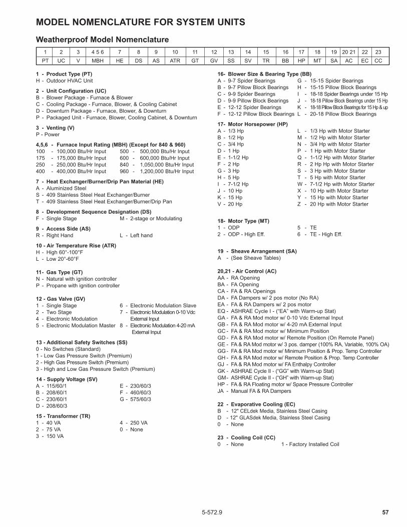
575-572.9
1 - Product Type (PT) H - Outdoor HVAC Unit
2 - Unit Configuration (UC) B - Blower Package - Furnace & Blower C - Cooling Package - Furnace, Blower, & Cooling Cabinet D - Downturn Package - Furnace, Blower, & Downturn P - Packaged Unit - Furnace, Blower, Cooling Cabinet, & Downturn
3 - Venting (V) P - Power
4,5,6 - Furnace Input Rating (MBH) (Except for 840 & 960) 100 - 100,000 Btu/Hr Input 500 - 500,000 Btu/Hr Input 175 - 175,000 Btu/Hr Input 600 - 600,000 Btu/Hr Input 250 - 250,000 Btu/Hr Input 840 - 1,050,000 Btu/Hr Input 400 - 400,000 Btu/Hr Input 960 - 1,200,000 Btu/Hr Input
7 - Heat Exchanger/Burner/Drip Pan Material (HE) A - Aluminized Steel S - 409 Stainless Steel Heat Exchanger/Burner T - 409 Stainless Steel Heat Exchanger/Burner/Drip Pan
8 - Development Sequence Designation (DS) F - Single Stage M - 2-stage or Modulating
9 - Access Side (AS) R - Right Hand L - Left hand
10 - Air Temperature Rise (ATR) H - High 60°-100°F L - Low 20°-60°F 11 - Gas Type (GT) N - Natural with ignition controller P - Propane with ignition controller 12 - Gas Valve (GV) 1 - Single Stage 6 - Electronic Modulation Slave 2 - Two Stage 7 - Electronic Modulation 0-10 Vdc 4 - Electronic Modulation External Input 5 - Electronic Modulation Master 8 - Electronic Modulation 4-20 mA External Input
13 - Additional Safety Switches (SS) 0 - No Switches (Standard) 1 - Low Gas Pressure Switch (Premium) 2 - High Gas Pressure Switch (Premium) 3 - High and Low Gas Pressure Switch (Premium)
14 - Supply Voltage (SV) A - 115/60/1 E - 230/60/3 B - 208/60/1 F - 460/60/3 C - 230/60/1 G - 575/60/3 D - 208/60/3
15 - Transformer (TR) 1 - 40 VA 4 - 250 VA 2 - 75 VA 0 - None 3 - 150 VA
16 - Blower Size & Bearing Type (BB) A - 9-7 Spider Bearings G - 15-15 Spider Bearings B - 9-7 Pillow Block Bearings H - 15-15 Pillow Block Bearings C - 9-9 Spider Bearings I - 18-18 Spider Bearings under 15 Hp D - 9-9 Pillow Block Bearings J - 18-18 Pillow Block Bearings under 15 Hp E - 12-12 Spider Bearings K - 18-18 Pillow Block Bearings for 15 Hp & up F - 12-12 Pillow Block Bearings L - 20-18 Pillow Block Bearings
17 - Motor Horsepower (HP) A - 1/3 Hp L - 1/3 Hp with Motor Starter B - 1/2 Hp M - 1/2 Hp with Motor Starter C - 3/4 Hp N - 3/4 Hp with Motor Starter D - 1 Hp P - 1 Hp with Motor Starter E - 1-1/2 Hp Q - 1-1/2 Hp with Motor Starter F - 2 Hp R - 2 Hp Hp with Motor Starter G - 3 Hp S - 3 Hp with Motor Starter H - 5 Hp T - 5 Hp with Motor Starter I - 7-1/2 Hp W - 7-1/2 Hp with Motor Starter J - 10 Hp X - 10 Hp with Motor Starter K - 15 Hp Y - 15 Hp with Motor Starter V - 20 Hp Z - 20 Hp with Motor Starter
18 - Motor Type (MT) 1 - ODP 5 - TE 2 - ODP - High Eff. 6 - TE - High Eff.
19 - Sheave Arrangement (SA) A - (See Sheave Tables) 20,21 - Air Control (AC) AA - RA Opening BA - FA Opening CA - FA & RA Openings DA - FA Dampers w/ 2 pos motor (No RA) EA - FA & RA Dampers w/ 2 pos motor EQ - ASHRAE Cycle I - (“EA” with Warm-up Stat) GA - FA & RA Mod motor w/ 0-10 Vdc External Input GB - FA & RA Mod motor w/ 4-20 mA External Input GC - FA & RA Mod motor w/ Minimum Position GD - FA & RA Mod motor w/ Remote Position (On Remote Panel) GE - FA & RA Mod motor w/ 3 pos. damper (100% RA, Variable, 100% OA) GG - FA & RA Mod motor w/ Minimum Position & Prop. Temp Controller GH - FA & RA Mod motor w/ Remote Position & Prop. Temp Controller GJ - FA & RA Mod motor w/ FA Enthalpy Controller GK - ASHRAE Cycle II - (“GG” with Warm-up Stat) GM - ASHRAE Cycle II - (“GH” with Warm-up Stat) HP - FA & RA Floating motor w/ Space Pressure Controller JA - Manual FA & RA Dampers 22 - Evaporative Cooling (EC) B - 12" CELdek Media, Stainless Steel Casing D - 12" GLASdek Media, Stainless Steel Casing 0 - None 23 - Cooling Coil (CC) 0 - None 1 - Factory Installed Coil
MODEL NOMENCLATURE FOR SYSTEM UNITS
1 2 3 4 5 6 7 8 9 10 11 12 13 14 15 16 17 18 19 20 21 22 23 PT UC V MBH HE DS AS ATR GT GV SS SV TR BB HP MT SA AC EC CC
Weatherproof Model Nomenclature

58 5-572.9
THIS PAGE INTENTIONALLY LEFT BLANK

595-572.9
THIS PAGE INTENTIONALLY LEFT BLANK

Modine Manufacturing Company1500 DeKoven AvenueRacine, WI 53403 Phone: 1.800.828.4328 (HEAT) www.modinehvac.com© Modine Manufacturing Company 2015
As Modine Manufacturing Company has a continuous product improvement program, it reserves the right to change design and specifications without notice.
COMMERCIAL WARRANTYSeller warrants its products to be free from defects in material and workmanship, EXCLUSIVE, HOWEVER, of failures attributable to the use of materials substituted under emergency conditions for materials normally employed. This warranty covers replacement of any parts furnished from the factory of Seller, but does not cover labor of any kind and materials not furnished by Seller, or any charges for any such labor or materials, whether such labor, materials or charges thereon are due to replacement of parts, adjustments, repairs, or any other work done. This warranty does not apply to any equipment which shall have been repaired or altered outside the factory of Seller in any way so as, in the judgment of Seller, to affect its stability, nor which has been subjected to misuse, negligence, or operating conditions in excess of those for which such equipment was designed. This warranty does not cover the effects of physical or chemical properties of water or steam or other liquids or gases used in the equipment. BUYER AGREES THAT SELLER’S WARRANTY OF ITS PRODUCTS TO BE FREE FROM DEFECT IN MATERIAL AND WORKMANSHIP, AS LIMITED HEREIN, SHALL BE IN LIEU OF AND EXCLUSIVE OF ALL OTHER WARRANTIES, EITHER EXPRESS OR IMPLIED, WHETHER ARISING FROM LAW, COURSE OF DEALING, USAGE OF TRADE, OR OTHERWISE, THERE ARE NO OTHER WARRANTIES, INCLUDING WARRANTY OF MERCHANTABILITY OR FITNESS FOR PURPOSE, WHICH EXTEND BEYOND THE PRODUCT DESCRIPTION CONFIRMED BY BUYER AND SELLER AS OF THE DATE OF FINAL AGREEMENT.This warranty is void if the input to the product exceeds the rated input as indicated on the product serial plate by more than 5% on gas-fired and oil-fired units, or if the product in the judgment of SELLER has been installed in a corrosive atmosphere, or subjected to corrosive fluids or gases, been subjected to misuse, negligence, accident, excessive thermal shock, excessive humidity, physical damage, impact, abrasion, unauthorized alterations, or operation contrary to SELLER’S printed instructions, or if the serial number has been altered, defaced or removed.BUYER AGREES THAT IN NO EVENT WILL SELLER BE LIABLE FOR COSTS OF PROCESSING, LOST PROFITS, INJURY TO GOODWILL, OR ANY OTHER CONSEQUENTIAL OR INCIDENTAL DAMAGES OF ANY KIND RESULTING FROM THE ORDER OR USE OF ITS PRODUCT, WHETHER ARISING FROM BREACH OF WARRANTY, NONCONFORMITY TO ORDERED SPECIFICATIONS, DELAY IN DELIVERY, OR ANY LOSS SUSTAINED BY THE BUYER.
BUYER’S REMEDY FOR BREACH OF WARRANTY, EXCLUSIVE OF ALL OTHER REMEDIES PROVIDED BY LAW, IS LIMITED TO REPAIR OR REPLACEMENT AT THE FACTORY OF SELLER, ANY COMPONENT WHICH SHALL, WITHIN THE APPLICABLE WARRANTY PERIOD DEFINED HEREIN AND UPON PRIOR WRITTEN APPROVAL, BE RETURNED TO SELLER WITH TRANSPORTATION CHARGES PREPAID AND WHICH THE EXAMINATION OF SELLER SHALL DISCLOSE TO HAVE BEEN DEFECTIVE; EXCEPT THAT WHEN THE PRODUCT IS TO BE USED BY BUYER AS A COMPONENT PART OF EQUIPMENT MANUFACTURED BY BUYER, BUYER’S REMEDY FOR BREACH, AS LIMITED HEREIN, SHALL BE LIMITED TO ONE YEAR FROM DATE OF SHIPMENT FROM SELLER. FOR GAS-FIRED PRODUCTS INSTALLED IN HIGH HUMIDITY APPLICATIONS AND UTILIZING STAINLESS STEEL HEAT EXCHANGERS, BUYER’S REMEDY FOR BREACH, AS LIMITED HEREIN, SHALL BE LIMITED TO TEN YEARS FROM DATE OF SHIPMENT FROM SELLER.These warranties are issued only to the original owner-user and cannot be transferred or assigned. No provision is made in these warranties for any labor allowance or field labor participation. Seller will not honor any expenses incurred in its behalf with regard to repairs to any of Seller’s products. No credit shall be issued for any defective part returned without proper written authorization (including, but not limited to, model number, serial number, date of failure, etc.) and freight prepaid. OPTIONAL SUPPLEMENTAL WARRANTYProvided a supplemental warranty has been purchased, Seller extends the warranty herein for an additional four (4) years on certain compressors. Provided a supplemental warranty has been purchased, Seller extends the warranty herein for an additional four (4) years or nine (9) years on certain heat exchangers.
EXCLUSION OF CONSUMABLES & CONDITIONS BEYOND SELLER’S CONTROLThis warranty shall not be applicable to any of the following items: refrigerant gas, belts, filters, fuses and other items consumed or worn out by normal wear and tear or conditions beyond Seller’s control, including (without limitation as to generality) polluted or contaminated or foreign matter contained in the air or water utilized for heat exchanger (condenser) cooling or if the failure of the part is caused by improper air or water supply, or improper or incorrect sizing of power supply.
Component
Applicable Models“APPLICABLE WARRANTY PERIOD”
Heat Exchangers Gas-Fired Units except MPR Models
Heat ExchangersLow Intensity Infrared Units , Gas Heat option on MPR modelsCompressorsCondensing Units for Cassettes
BurnersLow Intensity Infrared UnitsCompressorsMPR ModelsOtherComponents excluding Heat Exchangers, Coils, Condensers, Burners, Sheet Metal
Heat Exchangers/Coils Indoor and Outdoor Duct Furnaces and System Units, Steam/Hot Water Units, Oil-Fired Units, Electric Units, Cassettes, Vertical Unit Ventilators
CompressorsVertical Unit Ventilators
BurnersHigh Intensity Infrared Units
Sheet Metal PartsAll Products
TEN YEARS FROM DATE OF FIRST BENEFICIAL USE BY BUYER OR ANY OTHER USER, WITHIN TEN YEARS FROM DATE OF RESALE BY BUYER OR ANY OTHER USER, WITHIN TEN YEARS FROM DATE OF RESALE BY BUYER IN ANY UNCHANGED CONDITION, OR WITHIN ONE HUNDRED TWENTY-SIX MONTHS FROM DATE OF SHIPMENT FROM SELLER, WHICHEVER OCCURS FIRST
FIVE YEARS FROM DATE OF FIRST BENEFICIAL USE BY BUYER OR ANY OTHER USER, WITHIN FIVE YEARS FROM DATE OF RESALE BY BUYER OR ANY OTHER USER, WITHIN FIVE YEARS FROM DATE OF RESALE BY BUYER IN ANY UNCHANGED CONDITION, OR WITHIN SIXTY-SIX MONTHS FROM DATE OF SHIPMENT FROM SELLER, WHICHEVER OCCURS FIRST
TWO YEARS FROM DATE OF FIRST BENEFICIAL USE BY BUYER OR ANY OTHER USER, WITHIN TWO YEARS FROM DATE OF RESALE BY BUYER IN ANY UNCHANGED CONDITION, OR WITHIN THIRTY MONTHS FROM DATE OF SHIPMENT FROM SELLER, WHICHEVER OCCURS FIRST
ONE YEAR FROM DATE OF FIRST BENEFICIAL USE BY BUYER OR ANY OTHER USER, WITHIN ONE YEAR FROM DATE OF RESALE BY BUYER IN ANY UNCHANGED CONDITION, OR WITHIN EIGHTEEN MONTHS FROM DATE OF SHIPMENT FROM SELLER, WHICHEVER OCCURS FIRST