all rights reserved. reproduction by any means, … · new vehicle break-in your vehicle does not...
TRANSCRIPT

Introduction 2
Diesel information 4
Warning lights 7
Starting 9
Driving tips 14
General maintenance information 19
Scheduled maintenance 32
Minor troubleshooting guide 33
Capacities and specifications 36
Service points 38
All rights reserved. Reproduction by any means, electronic or mechanicalincluding photocopying, recording or by any information storage and retrievalsystem or translation in whole or part is not permitted without writtenauthorization from Ford Motor Company.
Copyright r 1998 Ford Motor Company
Table of contents
1

The following warning may be required by California law:
California Proposition 65 Warning: Diesel engine exhaust, someof its constituents, and certain vehicle components contain or
may emit chemicals known to the State of California to cause cancer orbirth defects or other reproductive harm.
Your new diesel engine will feel, drive and function somewhat differentlythan a gasoline engine. Therefore it is very important that you read andthoroughly familiarize yourself and others operating the vehicle with thisguide.
This guide will acquaint you with the Power Stroke (7.3L DIT) dieselengine. It provides recommendations on engine care and operatingprocedures. For complete vehicle information, also refer to the OwnerGuide included with the vehicle. It also describes equipment and givesspecifications for equipment that was in effect when this guide wasapproved for printing, and should be considered a permanent part of thevehicle.
Ford may discontinue models or change specifications without any noticeand without incurring obligations.
IMPORTANT NOTICEFord vehicles are suitable for producing ambulances only if equippedwith the Ford Ambulance Preparation Package. In addition, Fordurges ambulance manufacturers to follow the recommendation of theFord Incomplete Vehicle Manual, Ford Truck Body Builder’s LayoutBook (and pertinent supplements) and the “Qualified Vehicle ModifiersGuidelines.” Using a Ford vehicle without the Ford AmbulancePreparation Package to produce an ambulance voids the Ford warrantyand could result in elevated underbody temperatures, fueloverpressurization and the risk of fuel expulsion and fires. To determinewhether the vehicle is equipped with the Ford Ambulance PreparationPackage, inspect the information plate on the driver’s side door pillar.Contact the manufacturer of your vehicle to determine whether theambulance manufacturer’s followed Ford’s recommendations.
WARNINGSThroughout this guide, you will find warnings. Warnings remind you tobe especially careful to avoid personal injury.
Introduction
2
NEW VEHICLE BREAK-INYour vehicle does not need an extensive break-in. Try not to drivecontinuously at the same speed for the first 1 600 km (1 000 miles) ofnew vehicle operation. Vary your speed to allow parts to adjustthemselves to other parts.
Drive your new vehicle at least 800 km (500 miles) before towing atrailer.
Do not add friction modifier compounds or special break-in oils duringthe first few thousand kilometers (miles) of operation, since theseadditives may prevent piston ring seating. See “Engine oil” in theGeneral Maintenance Information chapter for more information on oilusage.
Introduction
3
DIESEL ENGINE INFORMATIONThe diesel engine fuel system consists of:
• a frame-mounted electric fuel supply pump
• an engine mounted fuel filter/water separator
• a fuel restriction sensor
• a unit injector for each cylinder
The combination fuel filter/water separator removes both water andimpurities from the fuel. The filter should be changed at therecommended service interval. Refer to the “Service Guide” for moreinformation. The filter bowl should be drained at regular intervals orwhen the “WATER IN FUEL” light illuminates in the instrument cluster.
The fuel injectors are located in the center of the combustion chambersin the cylinder head between the rocker arm assemblies. The glow plugsystem and fuel injection system are controlled through the powertraincontrol module (PCM).
Fuel is drawn from the fuel tank by a frame-mounted electric fuel pump.The fuel pump provides pressurized fuel to the engine and iselectronically controlled by the fuel pump PCM relay. The fuel pumpcontains a pressure relief valve for overpressure protection in the eventof restricted flow.
Lubrication systemIt is important to change the engine oil at the recommended serviceintervals, because oil viscosity is important in maintaining the oilpressure required to actuate the fuel injectors. Extended oil changeintervals can negatively affect engine performance and fuel economy.
The turbocharger, which is supplied pressurized oil, is also used toactuate an exhaust backpressure warm-up system (if equipped).Pressurized oil returning to the turbocharger is routed to the exhaustbackpressure actuator. During exhaust backpressure operation, theengine’s sound will be altered and you may notice a change in engineperformance while it’s engaged. This function occurs only during coldweather warm-up cycle.
Diesel information
4

Fast start glow plug systemThe glow plug system consists of:
• eight glow plugs
• the glow plug relay
• engine oil temperature (EOT) sensor
• barometric pressure (BARO) sensor
The glow plug system is electronically controlled by the PCM. The PCMenergizes the glow plugs immediately after the ignition is placed in theON position, then determines how long the glow plugs will be onaccording to the EOT and BARO sensors. The required time for the glowplugs to be energized decreases as the engine oil temperature andbarometric pressure increase.
Engine cooling systemThe cooling system contains an engine oil cooler which is mounted tothe side of the cylinder block. The cooler’s function is to regulate engineoil temperature.
Engine governed speedThe engine governor is controlled by the PCM. The PCM controls fuelinput to limit maximum engine speed. It will not, however, preventengine overspeeding resulting from downshifting at high vehicle speed orby descending steep grades at too high a vehicle speed for the selectedtransmission gear.
For maximum vehicle speed in various gears, refer to the “Transmissionshift speed” chart in the Driving tips chapter. Do not exceed 3,600 rpm.Maximum engine governed speed is 3,000–4,000 rpm depending onengine load. Excessive rpm can only be achieved by manuallydownshifting at too high of a vehicle speed.
Operating the engine beyond the governed speed can cause severeengine damage.
Diesel information
5
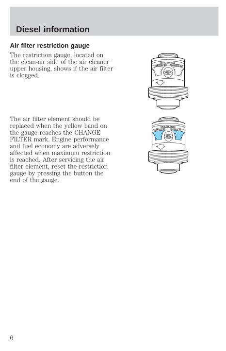
Air filter restriction gaugeThe restriction gauge, located onthe clean-air side of the air cleanerupper housing, shows if the air filteris clogged.
The air filter element should bereplaced when the yellow band onthe gauge reaches the CHANGEFILTER mark. Engine performanceand fuel economy are adverselyaffected when maximum restrictionis reached. After servicing the airfilter element, reset the restrictiongauge by pressing the button theend of the gauge.
AIR FILTER GAUGE
CHANGE FILTER CHANGE FILTER
AIR FILTER GAUGE
CHANGE FILTER CHANGE FILTER
Diesel information
6
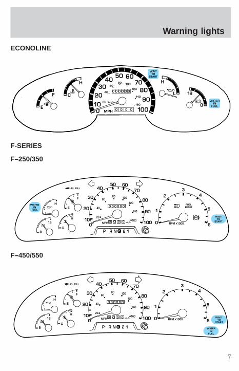
ECONOLINE
F-SERIES
F–250/350
F–450/550
010
2030
4050 60
7080
90
10020 km/h
40
6080 100
120
140
H
L
160
MPH
0 0 0 0 0 0
0 0 0 0
18
8
WAITTO
START
WATERIN
FUEL
F
H
C
E
0
0 0 0 0
0 0 0 0 0
MPH
20
km/h
40
6080 100
120
140
160
010
20
30
4050 60
70
80
90
100
WATERIN
FUEL
WAITTO
START
FUELRESET
ABS
L
E
F
H
RPM 1000X0
1
23
5
6
4
P R N 2 18C
18
H
D
FUEL FILL
0
0 0 0 0
0 0 0 0 0
MPH
20
km/h
40
6080 100
120
140
160
010
20
30
4050 60
70
80
90
100 WAIT TO
START
WATERIN
FUEL
L
E
F
H
RPM 1000X0
1
23
5
6
4
P R N 2 18C
18
H
D
FUEL FILL
Warning lights
7

WAIT TO STARTWith the key in the ON position, theWAIT TO START light will illuminateif glow plug heat is necessary as astarting aid. Wait until the light goesoff before starting. The light shouldalways illuminate briefly, when the ignition key is in the ON position. Ifthe light does not illuminate, there may be a problem. Refer to theStarting chapter in this guide. After the engine starts, the light shouldremain off.
The light should always illuminate at least momentarily when the engineis cold and the ignition is turned to ON. If it does not illuminate, theglow plug system should be checked and repaired promptly to avoiddifficulty in cold starting.
WATER IN FUELDuring refueling, it is possible forwater-contaminated diesel fuel to bepumped into your tank. Your vehiclefuel system is equipped with a fuelfilter/water separator to removewater from the fuel. The WATER IN FUEL light will illuminate when theignition is turned to START (as part of the light function check) andwhen the fuel filter/water separator has a significant quantity of water init.
If the light illuminates when the engine is running, stop the vehicle assoon as safely possible, shut off the engine, then drain the filter bowl.Refer to the General maintenance chapter for drain procedure.Allowing water to stay in the system could result in extensive damage to,or failure of, the fuel injection system.
Do not drain the water separator while the engine is running.Fuel may ignite if the separator is drained while the engine is
running or the vehicle is moving.
WAITTO
START
WATERIN
FUEL
Warning lights
8

STARTING THE ENGINERead all starting instructions carefully before you start your vehicle.Starting procedures are also shown on the vehicle visor. Fortemperatures below 0°C (32°F), the use of the correct grade engine oil isessential for proper operation.
If your vehicle is equipped with a manual transmission, make sure theparking brake is set fully before you turn the key. Depress the clutchpedal and place the gearshift in the neutral position. The clutch must befully depressed in order to operate the starter. Do not press theaccelerator during starting.
If your vehicle is equipped with an automatic transmission, ensure thegearshift lever is in P (Park) and the parking brake is set before you turnthe key. Do not press the accelerator during starting.
COLD WEATHER STARTINGDo not crank the engine for more than 30 seconds at a time as starterdamage may occur. If the engine fails to start, turn the key to OFF andwait 30 seconds before trying again.
Do not use starting fluid such as ether in the air intake system (see AirCleaner Decal). Such fluid could cause immediate explosive damage tothe engine and possible personal injury.
Do not add gasoline, gasohol or alcohol to diesel fuel. This practicecreates a serious fire hazard and causes engine performance problems.
1. Make sure all vehicle occupants have buckled their safety belts. Formore information on safety belts and their proper usage, refer to Seatingand safety restraints chapter in the owner guide.
2. Make sure the headlamps and vehicle accessories are off.
3. Turn the key to the ON position.When the WAIT TO START lightgoes off, turn the key to START.(For Canadian vehicles, the daytimerunning lamps will be on if theparking brake is not applied and the key is turned to ON.)
4. When the engine starts, release the key. The glow plugs will continueto be activated for up to two minutes. If the engine is not started beforethe activation ceases, the glow plug system must be reset by turning theignition key to OFF.
WAITTO
START
Starting
9
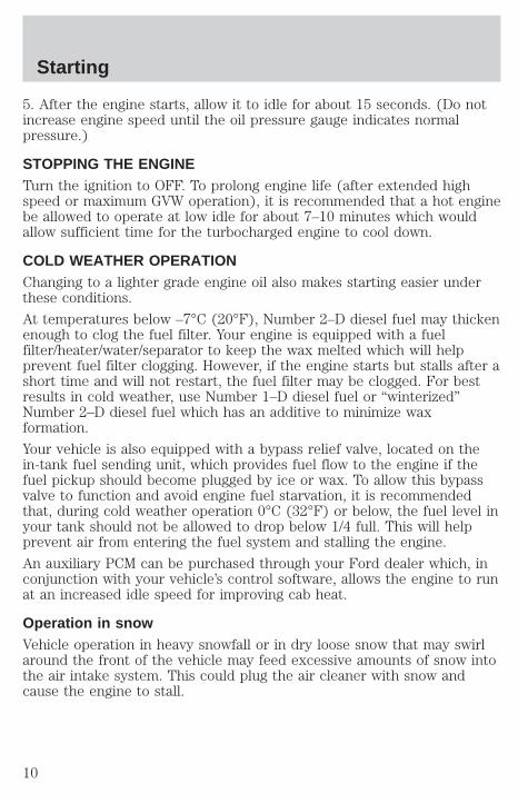
5. After the engine starts, allow it to idle for about 15 seconds. (Do notincrease engine speed until the oil pressure gauge indicates normalpressure.)
STOPPING THE ENGINETurn the ignition to OFF. To prolong engine life (after extended highspeed or maximum GVW operation), it is recommended that a hot enginebe allowed to operate at low idle for about 7–10 minutes which wouldallow sufficient time for the turbocharged engine to cool down.
COLD WEATHER OPERATIONChanging to a lighter grade engine oil also makes starting easier underthese conditions.
At temperatures below –7°C (20°F), Number 2–D diesel fuel may thickenenough to clog the fuel filter. Your engine is equipped with a fuelfilter/heater/water/separator to keep the wax melted which will helpprevent fuel filter clogging. However, if the engine starts but stalls after ashort time and will not restart, the fuel filter may be clogged. For bestresults in cold weather, use Number 1–D diesel fuel or “winterized”Number 2–D diesel fuel which has an additive to minimize waxformation.
Your vehicle is also equipped with a bypass relief valve, located on thein-tank fuel sending unit, which provides fuel flow to the engine if thefuel pickup should become plugged by ice or wax. To allow this bypassvalve to function and avoid engine fuel starvation, it is recommendedthat, during cold weather operation 0°C (32°F) or below, the fuel level inyour tank should not be allowed to drop below 1/4 full. This will helpprevent air from entering the fuel system and stalling the engine.
An auxiliary PCM can be purchased through your Ford dealer which, inconjunction with your vehicle’s control software, allows the engine to runat an increased idle speed for improving cab heat.
Operation in snowVehicle operation in heavy snowfall or in dry loose snow that may swirlaround the front of the vehicle may feed excessive amounts of snow intothe air intake system. This could plug the air cleaner with snow andcause the engine to stall.
Starting
10

Operation in standing waterIngestion of water into the diesel engine can result in immediate andsevere damage to the engine. If driving through water, slow down toavoid splashing water into the intake. If the engine stalls, and ingestionof water into the engine is suspected, do not try to restart the engine.Consult your dealer for service immediately. Follow the cylindercompression test procedure outlined in the Workshop Manual, thencheck the engine oil for contamination.
Engine block heater (if equipped)Refer to the Starting chapter in your Owner Guide.
JUMP STARTING YOUR VEHICLE
The gases around the battery can explode if exposed to flames,sparks, or lit cigarettes. An explosion could result in injury or
vehicle damage.
Do not push start your vehicle. You could damage the catalyticconverter.
Batteries contain sulfuric acid which burns skin, eyes, andclothing.
Preparing your vehicleAlso see the label on the battery.
1. Use only a 12–volt supply to start your vehicle. If you connect yourbattery to a 24–volt power supply you can damage your starter, ignitionsystem and other electrical components. Do not attach the jumper cablesto the glow plug relay as this could severely damage the glow plugs,injector driver module and PCM.
2. Do not disconnect the battery of the disabled vehicle as this coulddamage the vehicle’s electrical system.
3. Park the booster vehicle close to the hood of the disabled vehiclemaking sure they do not touch. Set the parking brake on both vehiclesand stay clear of the engine cooling fan and other moving parts.
Starting
11
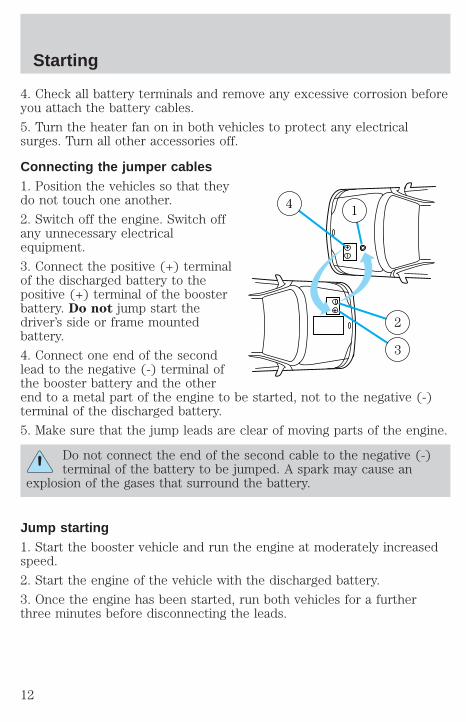
4. Check all battery terminals and remove any excessive corrosion beforeyou attach the battery cables.
5. Turn the heater fan on in both vehicles to protect any electricalsurges. Turn all other accessories off.
Connecting the jumper cables1. Position the vehicles so that theydo not touch one another.
2. Switch off the engine. Switch offany unnecessary electricalequipment.
3. Connect the positive (+) terminalof the discharged battery to thepositive (+) terminal of the boosterbattery. Do not jump start thedriver’s side or frame mountedbattery.
4. Connect one end of the secondlead to the negative (-) terminal ofthe booster battery and the otherend to a metal part of the engine to be started, not to the negative (-)terminal of the discharged battery.
5. Make sure that the jump leads are clear of moving parts of the engine.
Do not connect the end of the second cable to the negative (-)terminal of the battery to be jumped. A spark may cause an
explosion of the gases that surround the battery.
Jump starting1. Start the booster vehicle and run the engine at moderately increasedspeed.
2. Start the engine of the vehicle with the discharged battery.
3. Once the engine has been started, run both vehicles for a furtherthree minutes before disconnecting the leads.
+
–
+
–
4 1
2
3
Starting
12
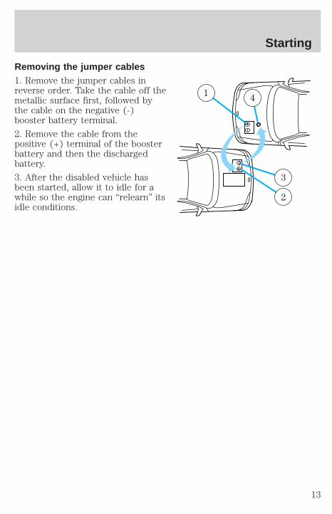
Removing the jumper cables1. Remove the jumper cables inreverse order. Take the cable off themetallic surface first, followed bythe cable on the negative (-)booster battery terminal.
2. Remove the cable from thepositive (+) terminal of the boosterbattery and then the dischargedbattery.
3. After the disabled vehicle hasbeen started, allow it to idle for awhile so the engine can “relearn” itsidle conditions.
+
–
+
–
1 4
3
2
Starting
13

TRANSMISSION SHIFT SPEEDSDo not overspeed the engine when going downhill or steep grades. Donot allow engine speed to exceed the redline area of the tachometer.Operating the engine beyond the governed speed can cause severeengine damage.
Upshift and downshift according to the following shift speed charts:
Upshifts when accelerating (recommended for best fuel economy)
6-speed transmission
Shift from: Transfer case position1 (if equipped)2H or 4H 4L
LO-1 8 km/h (5 mph) 3 km/h (2 mph)1-2 16 km/h (10 mph) 6 km/h (4 mph)2-3 32 km/h (20 mph) 13 km/h (8 mph)3-4 48 km/h (30 mph) 19 km/h (12 mph)
4 - D (Overdrive) 64 km/h (40 mph) 24 km/h (15 mph)
Maximum downshift speeds 1
6-speed transmission
Shift from: Transfer case position (if equipped)2
2H or 4H 4LD (Overdrive) - 4 72 km/h (45 mph) 26 km/h (16 mph)
4-3 56 km/h (35 mph) 19 km/h (12 mph)3-2 32 km/h (20 mph) 13 km/h (8 mph)2-1 8 km/h (5 mph) 3 km/h (2 mph)
1-LO Only shift to LO when at a stop.1 Use 2H or 4H for 4WD equipped vehicles.2 Downshift at lower speeds when driving on slippery surfaces.
TRAILER TOWINGRefer to your “Owner Guide” for full details on towing a trailer.
Econoline trailer towing tablesYour vehicle may tow a class I, II or III trailer provided the maximumtrailer weight is less than or equal to the maximum trailer weight listedfor your engine and rear axle ratio on the following charts.
Driving tips
14
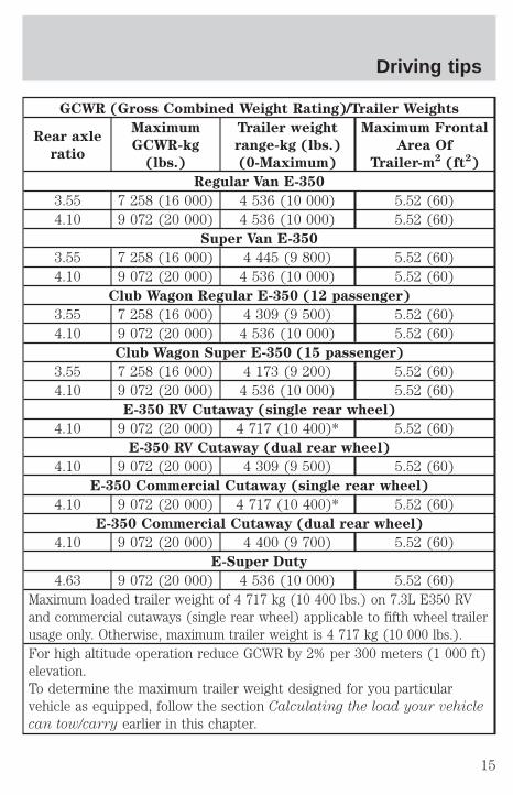
GCWR (Gross Combined Weight Rating)/Trailer Weights
Rear axle
ratio
Maximum
GCWR-kg
(lbs.)
Trailer weight
range-kg (lbs.)
(0-Maximum)
Maximum Frontal
Area Of
Trailer-m2 (ft2)
Regular Van E-350
3.55 7 258 (16 000) 4 536 (10 000) 5.52 (60)4.10 9 072 (20 000) 4 536 (10 000) 5.52 (60)
Super Van E-350
3.55 7 258 (16 000) 4 445 (9 800) 5.52 (60)4.10 9 072 (20 000) 4 536 (10 000) 5.52 (60)
Club Wagon Regular E-350 (12 passenger)
3.55 7 258 (16 000) 4 309 (9 500) 5.52 (60)4.10 9 072 (20 000) 4 536 (10 000) 5.52 (60)
Club Wagon Super E-350 (15 passenger)
3.55 7 258 (16 000) 4 173 (9 200) 5.52 (60)4.10 9 072 (20 000) 4 536 (10 000) 5.52 (60)
E-350 RV Cutaway (single rear wheel)
4.10 9 072 (20 000) 4 717 (10 400)* 5.52 (60)E-350 RV Cutaway (dual rear wheel)
4.10 9 072 (20 000) 4 309 (9 500) 5.52 (60)E-350 Commercial Cutaway (single rear wheel)
4.10 9 072 (20 000) 4 717 (10 400)* 5.52 (60)E-350 Commercial Cutaway (dual rear wheel)
4.10 9 072 (20 000) 4 400 (9 700) 5.52 (60)E-Super Duty
4.63 9 072 (20 000) 4 536 (10 000) 5.52 (60)Maximum loaded trailer weight of 4 717 kg (10 400 lbs.) on 7.3L E350 RVand commercial cutaways (single rear wheel) applicable to fifth wheel trailerusage only. Otherwise, maximum trailer weight is 4 717 kg (10 000 lbs.).For high altitude operation reduce GCWR by 2% per 300 meters (1 000 ft)elevation.To determine the maximum trailer weight designed for you particularvehicle as equipped, follow the section Calculating the load your vehicle
can tow/carry earlier in this chapter.
Driving tips
15
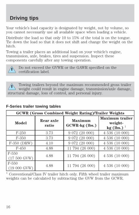
Your vehicle’s load capacity is designated by weight, not by volume, soyou cannot necessarily use all available space when loading a vehicle.
Distribute the load so that only 10 to 15% of the total is on the tongue.Tie down the load so that it does not shift and change the weight on thehitch.
Towing a trailer places an additional load on your vehicle’s engine,transmission, axle, brakes, tires and suspension. Inspect thesecomponents carefully after any towing operation.
Do not exceed the GVWR or the GAWR specified on thecertification label.
Towing trailers beyond the maximum recommended gross trailerweight could result in engine damage, transmission/axle damage,
structural damage, loss of control, and personal injury.
F-Series trailer towing tables
GCWR (Gross Combined Weight Rating)/Trailer Weights
ModelRear axle
ratio
Maximum
GCWR-kg (lbs.)
Maximum trailer
weight-
kg (lbs.) 1
F-250 3.73 9 072 (20 000) 4 536 (10 000)F-350 3.73 9 072 (20 000) 4 536 (10 000)
F-350 (DRW) 4.10 9 072 (20 000) 4 536 (10 000)F-450 4.88 11 794 (26 000) 4 536 (10 000)
F-550(17 500 GVW)
4.88 11 794 (26 000) 4 536 (10 000)
F-550(19 000 GVW)
4.88 11 794 (26 000) 4 536 (10 000)
1 Conventional/Class IV trailer hitch only. Fifth wheel trailer maximumweights can be calculated by subtracting the GVW from the GCWR.
Driving tips
16

AUXILIARY POWERTRAIN CONTROL MODULE (APCM)(IF EQUIPPED)Your vehicle may be equipped with an auxiliary PCM. It has the followingfeatures:
RPM controlThis feature is used for elevating theengine’s idle speed. Rpm control canbe activated from inside the vehicleand can be programmed to activateautomatically upon engine start-up.Programmable speed presets rangefrom 1300–2500 rpm. This is therecommended method of elevatingidle speed for PTO applications.
Charge ProtectThis feature is used for maintainingbattery charge. In “ChargeProtection” mode, the batteryvoltage is monitors and the engineidle speed is increased so thebattery charge is maintained asrequired. Charge Protection can beactivated from inside the vehicleand programmed to activateautomatically upon engine start-up.
LCD screenDisplays current engine speed andbattery voltage.
RPMCONTROL
CHARGEPROTECT POWER
RPMCONTROL
CHARGEPROTECT POWER
RPMCONTROL
CHARGEPROTECT POWER
Driving tips
17
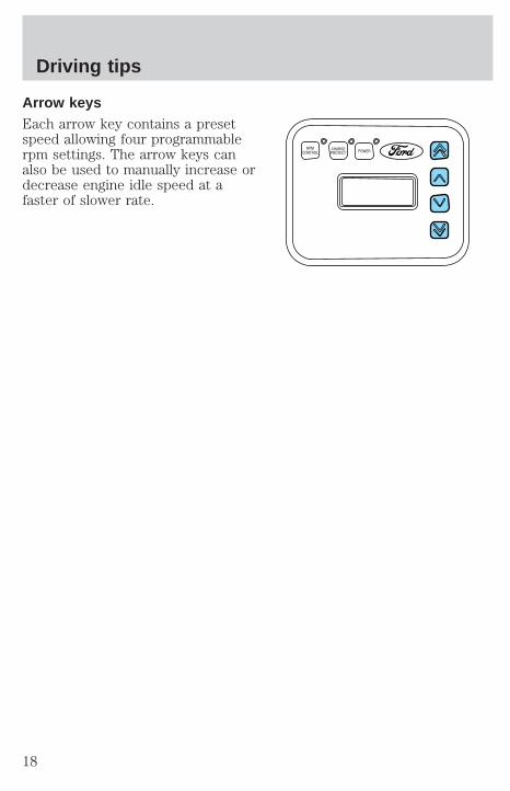
Arrow keysEach arrow key contains a presetspeed allowing four programmablerpm settings. The arrow keys canalso be used to manually increase ordecrease engine idle speed at afaster of slower rate.
RPMCONTROL
CHARGEPROTECT POWER
Driving tips
18

SCHEDULED MAINTENANCEThe Scheduled Maintenance Services in the Service Guide are requiredbecause they are considered essential to the life and performance ofyour vehicle.
Use only recommended fuel, lubricants, fluids and service partsconforming to Ford specifications. Motorcraft parts are designed andbuilt for best performance in your vehicle.
WASHING THE DIESEL ENGINENever wash the engine when it is warm, hot or running. Spraying wateror other cleaning fluids on a warm engine can seriously damage theengine’s fuel system. When washing the engine, the air cleaner must bein place to prevent water from splashing into the engine.
FUEL REQUIREMENTSThe engine is designed to use low sulfur number 1–D or 2–D diesel fuelonly. At temperatures below -7°C (20°F), number 1–D or winter blendnumber 2–D fuel is recommended. (See “Cold Weather Operation” in theStarting chapter.)
Do not use fuel intended for agricultural use (agricultural fuel isdyed red), home heating oil or any diesel fuel not intended forhighway use. Damage to the fuel injection system or engine canoccur if an improper fuel is used.
Do not add gasoline, gasohol or alcohol to diesel fuel. This practicecreates a serious fire hazard and engine performance problems.
It should not be necessary to add any aftermarket additives to your fueltank if you use a properly formulated diesel fuel that meets the ASTM D975 industry specification. Aftermarket additives can damage the injectorsystem or engine.
Do not blend used engine oil with diesel fuel under any circumstances.Blending used oil with the fuel will significantly increase your vehicle’sexhaust emissions and reduce engine life due to increased internal wear.
Do not crank the engine for more than 30 seconds at a time asdamage to the starter motor may result.
If the engine fails to start in 30 seconds, turn the key to the OFFposition and wait 30 seconds before trying again.
General maintenance information
19

Truck stops have pumps and nozzles designed for larger, heavy-dutytrucks. When refueling at truck stops: if the nozzle shuts off repeatedlywhen refueling, wait 5–10 seconds; then use a slower rate of flow (don’tdepress the nozzle trigger as far).
If air is allowed to enter the fuel system (during fuel filter change or ifyou run out of fuel) the engine will purge the trapped air as it runs. Theengine may run rough and produce white smoke while air is in thesystem. This is normal and should correct itself in a short time.
An engine that suddenly becomes noisy or operates poorly after a fuel fillcould be using substandard fuel (i.e., high water content, low octanerating or gasoline in the fuel). Diesel fuel should be purchased from areputable station which sells a large amount of diesel fuel.
Care should be taken whenever diesel fuel is stored. Use only clean,approved containers which will prevent the entry of dirt or water.
Diesel fuel must not be stored in a galvanized container. The fuel willdissolve the zinc in a galvanized container. The zinc will then remain insolution until it is run through the engine where it will be deposited inthe fuel injectors causing expensive-to-repair damage.
General maintenance information
20
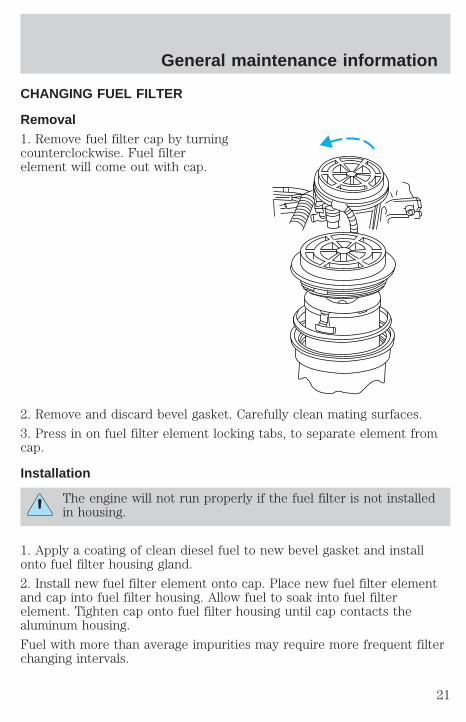
CHANGING FUEL FILTER
Removal1. Remove fuel filter cap by turningcounterclockwise. Fuel filterelement will come out with cap.
2. Remove and discard bevel gasket. Carefully clean mating surfaces.
3. Press in on fuel filter element locking tabs, to separate element fromcap.
Installation
The engine will not run properly if the fuel filter is not installedin housing.
1. Apply a coating of clean diesel fuel to new bevel gasket and installonto fuel filter housing gland.
2. Install new fuel filter element onto cap. Place new fuel filter elementand cap into fuel filter housing. Allow fuel to soak into fuel filterelement. Tighten cap onto fuel filter housing until cap contacts thealuminum housing.
Fuel with more than average impurities may require more frequent filterchanging intervals.
General maintenance information
21
After changing the fuel filter, the engine will purge the trapped air as itruns. Engine may run roughly and smoke until the air is completelyeliminated.
ENGINE OIL
Checking engine oil levelBecause it is normal to add some oil between oil changes, check yourengine oil level each time you stop for fuel. To check the engine oil levelconsistently and accurately, the following procedure is recommended:
1. Have engine at normal operating temperature (at least into theNORMAL range on the engine coolant temperature gauge).
2. Park the vehicle on a level surface, then turn off the engine and openthe hood.
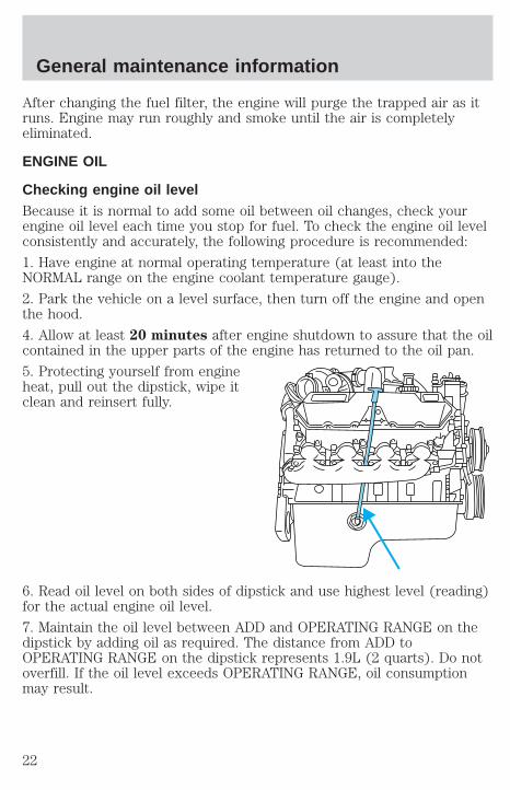
4. Allow at least 20 minutes after engine shutdown to assure that the oilcontained in the upper parts of the engine has returned to the oil pan.
5. Protecting yourself from engineheat, pull out the dipstick, wipe itclean and reinsert fully.
6. Read oil level on both sides of dipstick and use highest level (reading)for the actual engine oil level.
7. Maintain the oil level between ADD and OPERATING RANGE on thedipstick by adding oil as required. The distance from ADD toOPERATING RANGE on the dipstick represents 1.9L (2 quarts). Do notoverfill. If the oil level exceeds OPERATING RANGE, oil consumptionmay result.
General maintenance information
22
Engine oil specificationsTo help achieve proper engine performance and durability, it is importantthat only engine lubricating oils of the proper quality are used in yourdiesel engine and that the engine oil is changed no later than therecommended interval. Diesel engines require specially formulated oil toresist contamination. Proper quality oils also provide maximum efficiencyof the crankcase ventilating system which reduces air pollution.
For normal or severe service, use Motorcraft oil or an equivalent oilconforming to Ford Specification WSS-M2C171–C or API Servicecategories CG-4/SH. Do not use oil labeled with only one of the followingcategory designations; SG, SH, CE, CF-4, or CG-4, as they could causeengine damage.
Engine oils with improved fuel economy properties (energy conserving)are currently available. If you use an energy conserving oil, be sure itmeets the recommended Ford Specification, API service categories andSAE viscosity grades listed in the Lubricant and Maintenance MaterialsSpecifications chart. Some energy conserving oils do not meet therequirements necessary for your diesel engine.
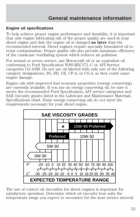
The use of correct oil viscosities for diesel engines is important forsatisfactory operation. Determine which oil viscosity best suits thetemperature range you expect to encounter for the next service interval.
SAE VISCOSITY GRADES
EXPECTED TEMPERATURE RANGE
F˚ -20 -10 0 10 20 30 40
4035302520151050-5-10-15-20-25-30C˚
50 60 70 80 90 100
* 15W-40 Preferred
10W-30
5W-30
0W-30
Preferred
General maintenance information
23
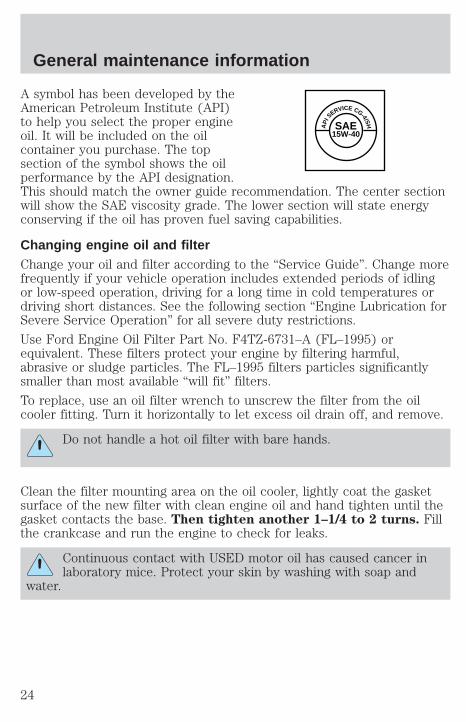
A symbol has been developed by theAmerican Petroleum Institute (API)to help you select the proper engineoil. It will be included on the oilcontainer you purchase. The topsection of the symbol shows the oilperformance by the API designation.This should match the owner guide recommendation. The center sectionwill show the SAE viscosity grade. The lower section will state energyconserving if the oil has proven fuel saving capabilities.
Changing engine oil and filterChange your oil and filter according to the “Service Guide”. Change morefrequently if your vehicle operation includes extended periods of idlingor low-speed operation, driving for a long time in cold temperatures ordriving short distances. See the following section “Engine Lubrication forSevere Service Operation” for all severe duty restrictions.
Use Ford Engine Oil Filter Part No. F4TZ-6731–A (FL–1995) orequivalent. These filters protect your engine by filtering harmful,abrasive or sludge particles. The FL–1995 filters particles significantlysmaller than most available “will fit” filters.
To replace, use an oil filter wrench to unscrew the filter from the oilcooler fitting. Turn it horizontally to let excess oil drain off, and remove.
Do not handle a hot oil filter with bare hands.
Clean the filter mounting area on the oil cooler, lightly coat the gasketsurface of the new filter with clean engine oil and hand tighten until thegasket contacts the base. Then tighten another 1–1/4 to 2 turns. Fillthe crankcase and run the engine to check for leaks.
Continuous contact with USED motor oil has caused cancer inlaboratory mice. Protect your skin by washing with soap and
water.
AP
I S
ERVICE CG-4/SHSAE15W-40
General maintenance information
24
Engine lubrication for severe service operationThe following severe service operating conditions require unique enginemaintenance procedures:
• towing a trailer over 1 600 km (1 000 miles)
• sustained, high speed driving at Gross Vehicle Weight Rating(maximum loaded weight for vehicle operation during hotweather-above 32°C [90°F]).
• frequent or extended idling (over 10 minutes per hour of normaldriving).
• operating in severe dust conditions.
• frequent, short trips of 16 km (10 miles) or less during freezingweather
If you are operating your vehicle under any of these conditions, observethe following service procedures:
• Change engine oil and filter every 5 000 km (3 000 miles).
• Use Motorcraft oil or an equivalent oil conforming to FordSpecification ESR-M2C171–C or API categories CG-4/SH. Do not useoils labeled with only one of the following category designations, SG,SH, CE, CF-4 or CG-4, as they could cause engine damage.
For more information refer the Severe Duty Maintenance Schedule inthe “Service Guide”.
REPLACING AIR CLEANERWhen replacing the air cleaner, use a Motorcraft filter or its equivalent.Refer to Lubricant and Maintenance Materials Specifications in thissupplement.
Failure to use the correct filter may result in severe enginedamage when driving through deep water and/or encountering
unusually heavy precipitation conditions.
1. Remove air cleaner, taking care to prevent dirt from falling into theengine air intake.
2. Clean the air cleaner tray and cover to ensure good sealing.
General maintenance information
25

3. After replacing the air cleaner, be sure that the rubber water drainhose is not kinked under the tray. If so, adjust the hose so that it hangsfree. Failure to do so may result in severe engine damage when drivingthrough deep water and/or encountering unusually heavy precipitationconditions.
FUEL FILTER/WATER SEPARATORThe engine is equipped with a combination fuel filter/water separatorlocated in the “V” of the engine.
Water should be drained from thefilter bowl whenever the warninglight comes on or every 8 000 km (5000 miles). The WATER IN FUELlight will come on whenapproximately 100 cc (0.2 pints) of water accumulates in the separator.
Replace the fuel filter with Motorcraft Part No. FD-4595–A (Ford PartNo. F4TZ-9N184–B).
Fuel filter/water separator drain procedure1. Stop the vehicle and shut off the engine.
The vehicle must be stopped with the engine off when drainingthe filter bowl. Fuel may ignite if separator is drained while the
engine is running or vehicle is moving.
2. Open the hood. Place anappropriate container under thefilter drain under the vehicle.
WATERIN
FUEL
General maintenance information
26

3. On F-Series models, open filterdrain valve by turning clockwise.Allow to drain for approximately 25seconds or until clean fuel isobserved. Close drain valve byturning counterclockwise until firmlyseated.
3. On Econoline models, open filter drain valve release handle. Allowto drain for approximately 25 seconds or until clean fuel is observed.Close drain valve by resetting handle to original position.
4. On all models, verify that the fuel drain is closed. Close the hood andremove the container from under the vehicle.
5. Restart the engine and check WATER IN FUEL indicator light. Thelight should not glow. If it continues to glow, have fuel system checkedand repaired.
DR
AIN
CLOSE
General maintenance information
27
ENGINE COOLANT
Replacing coolantA coolant mixture of 50% coolant concentrate and 50% water isrecommended to maintain best overall performance. To avoid damagingthe engine and radiator, the coolant concentrate should not exceed 60%.When refilling the coolant system either as part of the regularmaintenance (48 months, or 80 000 km [50 000 miles], whichever comesfirst and then every 36 months or 48 000 km [30 000 miles], whichevercomes first), or due to service performed, adhere to the followinginstructions:
1. Drain and flush the cooling system to remove dirt deposits, oil, rustparticles.
2. Add 1.89L (4 pints) of supplemental coolant additive FW-15, directlyto the cooling system. An additional 237–295 ml (8–10 oz.) ofsupplemental coolant additive FW-15 should be added at 24 000 km (15000 mile) intervals to maintain proper concentration.
3. Fill the coolant reservoir with the specified coolant/water mixture untilthe level stabilizes at the top hose fitting. Replace and tighten cap. Fillthe radiator when cold. Level the coolant in the coolant bottle.
4. Reinstall the coolant bottle cap.
5. Start and idle engine until the radiator upper hose is warm(approximately 10–15 minutes). If the hose does not get warm thenrepeat at a higher engine speed.
6. Immediately shut off engine. Cautiously remove coolant bottle cap andadd coolant to Cold Fill mark.
Checking coolant levelCheck coolant level in coolant reservoir bottle at least once a month,only when the engine is cool. Fill to within the “Cold Fill Level” rangenoted on the reservoir as required with a 50/50 mixture of coolantconcentrate and water.
A coolant mixture of 50% coolant concentrate and 50% water isrecommended to maintain best overall performance. A 60/40 antifreezeto water ratio is acceptable for extremely cold climates, but must bereturned to a 50/50 ratio at the end of the winter season.
Vehicles with diesel engines typically are used to carry heavy loads andaccumulate mileage rapidly. These two factors cause the additives in the
General maintenance information
28

coolant to “wear out” in a shorter time. Ford recommends an interimservice interval performed at 12 months or 24 000 km (15 000 miles),whichever occurs first. Add 237–295 ml (8–10 oz.) of supplementalcoolant additive FW-15 to the cooling system. For vehicles with extensiveidling time, add 237–295 ml (8–10 oz.) of coolant additive FW-15 afterevery 500 hours of operation.
Operating engine with insufficient coolant and/or coolant additive cancause severe engine damage.
Failure to follow these instructions could result in seriouspersonal injury from hot coolant or steam blow out and/or
damage to the cooling system or engine. Never remove the coolantbottle cap under any circumstances while the engine is operating.Switch off the engine and wait until it has cooled. Wrap a thick clotharound the cap and turn it slowly while the pressure is relieved. Stepback while the pressure is released from the cooling system. When youare sure all the pressure has been released, still with a cloth — turnand remove it. Stand clear of the opening. Hot coolant may splash out.
Whenever coolant level checks are made, check condition of coolantbottle cap rubber seal. Make sure it is clean and free of any dirtparticles. Rinse off with water, if necessary. When replacing cap oncoolant bottle, also make sure coolant bottle neck seal is clean. Checkthat overflow hose is not kinked.
Coolant specificationUse only a permanent-type coolant that meets Ford SpecificationESE-M97B44–A such as Ford Premium Cooling System FluidE2FZ-19549–AA. Do not use alcohol or methanol antifreeze or mix themwith the specified coolant.
Use of the wrong coolant may cause radiator and/or engine damage.
Plain water may be used in an emergency, but replace it with thespecified coolant as soon as possible to avoid damage to the system. Withonly water in the system, do not let the engine run hot or remain parkedin temperatures below 0°C (32°F).
Coolant conditioner (liquid)A supplemental coolant additive FW-15 has been added to the coolant inthis engine.
General maintenance information
29
This additive aids in the prevention of rust and scale buildup on theinternal parts of the cooling system. Prevention of rust and scale buildupallows for proper dissipation of heat generated by combustion.
See the “Service Guide” for recommended intervals.
EMISSION CONTROL SYSTEM(S) LAWSFederal law prohibits vehicle manufacturers, dealers and other personsengaged in the business of repairing, servicing, selling, leasing or tradingmotor vehicles as well as fleet operations from unknowingly removing orrendering emission control system(s) inoperative. Further, modificationsof the emission control system(s) could create liability on the part of theindividual owners under the laws of some states. In Canada,modifications of the emission control system(s) could create liabilityunder applicable Federal or Provincial laws.
Do not remove or alter the original equipment floor covering orinsulation between it and the metal floor of the vehicle. The floorcovering and insulation protect occupants of the vehicle from the engineand exhaust system heat and noise. On vehicles with no originalequipment floor covering insulation, do not carry passengers in a mannerthat permits prolonged skin contact with the metal floor. Provideadequate insulation.
NOISE EMISSIONS WARRANTY, PROHIBITED TAMPERING ACTSAND MAINTENANCEOn January 1, 1978, Federal regulation became effective governing thenoise emission on trucks over 4 536 kg (10 000 lbs.) GVWR (GrossVehicle Weight Rating). The following statements concerning prohibitedtampering acts and maintenance, and the noise warranty found in theWarranty Facts Booklet, are applicable to complete chassis cabs over4 536 (10 000 lbs.) GVWR.
Tampering with noise control system prohibitedFederal law prohibits the following acts or the causing thereof: (1) Theremoval or rendering inoperative by any person other than for purposesof maintenance, repair or replacement of any device or element of designincorporated into any new vehicle for the purpose of noise control priorto its sale or delivery to the ultimate purchaser or while it is in use, or(2) the use of the vehicle after such device or element of design hasbeen removed or rendered inoperative by any person.
General maintenance information
30

Among those acts which the U.S. Environmental Protection Agency maypresume to constitute tampering are the acts listed below:
• Removal of hood blanket, fender apron absorbers, fender apronbarriers, underbody noise shields or acoustically absorptive material.
• Tampering or rendering inoperative the engine speed governor, so asto allow engine speed to exceed manufacturer’s specifications.
General maintenance information
31
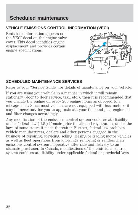
VEHICLE EMISSIONS CONTROL INFORMATION (VECI)Emissions information appears onthe VECI decal on the engine valvecover. This decal identifies enginedisplacement and provides certainengine specifications.
SCHEDULED MAINTENANCE SERVICESRefer to your “Service Guide” for details of maintenance on your vehicle.
If you are using your vehicle in a manner in which it will remainstationary (door to door service, taxi, etc.), then it is recommended thatyou change the engine oil every 200 engine hours as opposed to amileage limit. Since most vehicles are not equipped with hourmeters, itmay be necessary for you to approximate your time and plan engine oiland filter changes accordingly.
Any modification of the emissions control system could create liabilityunder federal law (U.S.) if made prior to sale and registration, under thelaws of some states if made thereafter. Further, federal law prohibitsvehicle manufacturers, dealers and other persons engaged in thebusiness of repairing, servicing, selling, leasing or trading motor vehiclesas well as fleet operations from knowingly removing or rendering anemissions control system inoperative after sale and delivery to anultimate purchaser. In Canada, modifications of the emissions controlsystem could create liability under applicable federal or provincial laws.
Scheduled maintenance
32

The complexity of the diesel engine makes it so the owner is discouragedfrom attempting to perform maintenance other than the servicesdescribed in this supplement.
If you experience difficult starting, rough idling, excessive exhaustsmoke, a decrease in engine performance or excess fuel consumption,perform the following checks:
• a plugged air inlet system.
• water in the fuel filter/water separator.
• a clogged fuel filter.
• contaminated fuel.
• air in the fuel system, due to loose connections.
• an open or pinched sensor hose.
• low engine oil level.
If these checks do not help you correct the engine performance problemyou are experiencing, consult an authorized dealer.
FUELING
Do not use starting fluid such as ether or gasoline in the dieselair intake system. Such fluids can cause immediate explosive
damage to the engine and possible personal injury.
If you fuel your vehicle at a truck stop, you may notice that the fuelnozzle may shut off every 5–10 seconds. This is due to the flow ratesbeing designed for larger heavy duty trucks. You may have to fuel at aslower rate (don’t depress the nozzle trigger fully).
Do not run your diesel vehicle out of fuel as this will allow air to enterthe fuel system which will make restarting difficult. Longer enginecranking time may be required once air is in the fuel system. If air entersthe fuel system (either through running the fuel tank(s) empty or duringa fuel filter change), the engine will self-purge the trapped air once itstarts running. The engine may run roughly and produce white smokewhile air is in the fuel system; this is normal and should stop after ashort time.
Minor troubleshooting guide
33

IF THE ENGINE WON’T CRANKTurn on the headlights. If the lights are dim, do not go on at all or ifwhen the ignition is turned to START the lights become dim or go out,the battery connections may be loose or corroded, or the battery may bedischarged. If there is a clicking or stuttering sound coming from theengine compartment when you turn the key to START, this may alsoindicate a loose or corroded battery connection.
Check the battery connections at the battery posts, cable connection tothe engine grounding point and at the starter relay terminals. Also, makesure the relay bracket is securely fastened to its mounting surface.
If the starter relay clicks, but the starter does not crank, check theconnections at the starter terminal. If a discharged battery is suspected,have it checked and corrected.
• For vehicles with manual transmissions, the clutch pedal must be fullydepressed in order for the starter to operate.
• For vehicles with automatic transmissions, the gearshift lever must bein Park or Neutral in order for the starter to operate.
• Try operating the starter switch several times. Should the switch becorroded, this operation may clean the contacts or make the switchtemporarily operable until you can reach the dealer.
• If all electrical connections are tight and you need assistance to start,see “Jump Starting Your Vehicle” in the Starting chapter.
IF ENGINE CRANKS BUT WON’T STARTProlonged starter cranking (in excess of 30 seconds) could causedamage to the starter motor.
• Check the fuel gauge. You may be out of fuel. If the gauge shows thatthere is fuel in the tank, the trouble may be in the electrical system orthe fuel system. If equipped with an auxiliary tank, be sure that thetank control switch is set for the tank with fuel and not on an emptytank.
• Leaving the ignition key ON for over two minutes without starting maymake starting difficult because the glow plugs will cease activation.Reset the system by turning the ignition key to OFF and then back toON again.
Minor troubleshooting guide
34
IF THE ENGINE RUNS HOTThe following could cause the engine to overheat:
• Lack of coolant.
• Dirty cooling system.
• Driving with frozen coolant.
• Sticking thermostat.
• Overloading or pulling heavy trailers during hot weather.
• Grill or radiator air blockage.
• Slipping or missing drive belt.
• Plugged or very dirty air cleaner element.
IF FUSES BURN OUTBurned-out or blown fuses usually indicate an electrical short-circuit,although a fuse may occasionally burn out from vibration. Insert a secondfuse. If this fuse immediately burns out and you cannot locate the cause,return your vehicle to your dealer for a circuit check.
Replacement fuses and circuit breakers must always be the samerating as the original equipment shown. Never replace a fuse or
circuit breaker with one of a higher rating. Higher rated fuses or circuitbreakers could allow circuit overloading in the event of a circuitmalfunction, resulting in severe vehicle damage or personal injury.
Refer to the “Owner Guide” for replacement of fuses.
Minor troubleshooting guide
35

REFILL CAPACITIES
Component Capacity
Cooling system (including heater1 )-F-Series 31.0L (32.75 quarts)Cooling system (including heater1 )-Econoline2 28.5L (30.0 quarts)Engine oil (including filter change)3 14.2 L (15.0 quarts)Fuel tank-F- Series Refer to Owner GuideFuel tank-Econoline 132.5L (35.0 gallons)Radiator cap 90 kPa (13 psi)Manual transmission4 3.2L (3.4 quarts)Automatic transmission Refer to Owner Guide
1 Includes 4.7L (5 quarts) in coolant recovery.2 Add 2.5L (2.6 quarts) if equipped with auxiliary heater option.3 Includes 1.9L (2 quarts) in engine oil filter.4 Use Motorcraft MERCONt ATF, Ford part number XT-2–QDX, meetingFord specification MERCONt.
BULB SPECIFICATIONS
Lamp descriptionNumber of bulbs
required
Trade number
Wait to Start Light 1 194Water-in-Fuel Light 1 194Engine Temp. Light 1 194
Fuel Filter 1 194
Capacities and specifications
36
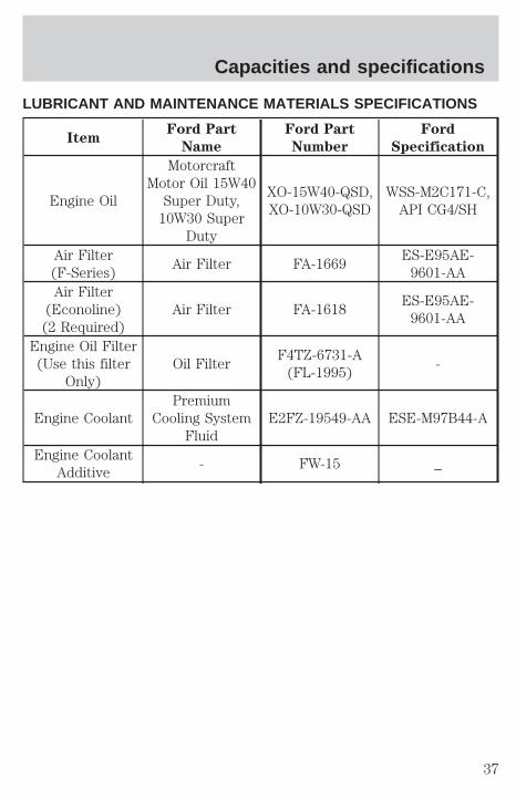
LUBRICANT AND MAINTENANCE MATERIALS SPECIFICATIONS
ItemFord Part
Name
Ford Part
Number
Ford
Specification
Engine Oil
MotorcraftMotor Oil 15W40
Super Duty,10W30 Super
Duty
XO-15W40-QSD,XO-10W30-QSD
WSS-M2C171-C,API CG4/SH
Air Filter(F-Series)
Air Filter FA-1669ES-E95AE-
9601-AAAir Filter
(Econoline)(2 Required)
Air Filter FA-1618ES-E95AE-
9601-AA
Engine Oil Filter(Use this filter
Only)Oil Filter
F4TZ-6731-A(FL-1995)
-
Engine CoolantPremium
Cooling SystemFluid
E2FZ-19549-AA ESE-M97B44-A
Engine CoolantAdditive
- FW-15 _
Capacities and specifications
37
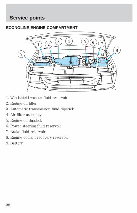
ECONOLINE ENGINE COMPARTMENT
1. Windshield washer fluid reservoir
2. Engine oil filler
3. Automatic transmission fluid dipstick
4. Air filter assembly
5. Engine oil dipstick
6. Power steering fluid reservoir
7. Brake fluid reservoir
8. Engine coolant recovery reservoir
9. Battery
9
1 23 4 5 6 7
8
Service points
38

F-SERIES ENGINE COMPARTMENT
1. Engine coolant recovery reservoir
2. Engine oil filler
3. Engine oil dipstick
4. Automatic transmission dipstick (if equipped)
5. Clutch fluid reservoir (if equipped)
6. Brake fluid reservoir
7. Air filter assembly
8. Battery (dual batteries shown)
9. Power steering fluid reservoir
10. Windshield washer fluid reservoir
10 9
1 2 3 4 5 6 7 88
Service points
39