all season roll-up doors - tmi motor injamb v.2.pdf · all season roll-up doors ... if the carton...
TRANSCRIPT

SCREEN-PRO ™
IN-JAMB MOUNTING METHOD
INSTALLATION INSTRUCTIONS
All Season Roll-Up Doors
In-Tube Motorized
Carefully examine the crate(s) for damage before opening. If the carton is damaged, immediately notify shippingcompany. Open the carton(s) and remove all protective packaging. Retain the shipping carton(s) until the unit(s) isinstalled and properly operating. TMI, LLC. is not responsible for delayed or late claims.
READ THIS FIRST
Group of Companies
Serial No: ________________ Model #: _______________ Date Purchased: ___________

TYPES OF DOORS
There are a variety of doors used at both industrial andcommercial facilities. Each has its specific opening/closingmechanism. This Screen-Pro unit has been shipped withhardware to accommodate an In-Jamb Mounting Method.It should be mounted inside a plain doorway opening usingthe door jambs to attach the Guide Tracks.
PLAINDOORWAYOPENING
OVERHEADDOOR
ROLL-UPDOOR
4
Screen Material withModular Panels
(Attached to Roller Drum)
LockStrap
GuideTracks
Top SpreaderAngle
Brush SealBar Brush Seal
Screen Roller Drum
MountingAngles
DrumMounting Plate
(Motor)
DrumMounting Bracket
(Bearing)
SCREEN-PRO COMPONENTS
–IMPORTANT –This Screen-Pro model has been designed to fit insidea doorway opening that has an 8'' jamb width or larger.
It is recommended that two peopleinstall the door together.
The following tools will be neededfor installation:
• Carpenter’s Level (Min. 4’ Length)
• Carpenter’s Square
• Hammer Drill
• Masonry Drill Bit (For 3/ 8” Diameter Anchors)
• 3/ 8” Diameter and Various Wall Anchors
• Assorted Shim Stock
• Socket and Wrench Set
• Hand Tools
• Four Bar Clamps (36” Long)
• Two Ladders
• Forklift (Supplied by Dealer or Customer)
REQUIRED TOOLS
Read and Save These Instructions
To Reduce the Risk of Fire, Electrical Shock, or Injury, Observe the Following:Warning
• Use this unit only in the manner intended by the manufacturer. If you have any questions, contact the manufacturer.• Installation work must be done by a qualified person(s) in accordance with all applicable codes and standards.• When cutting or drilling into wall or ceiling, do not damage electrical wiring and other hidden utilities.• All electrical work should be performed in accordance with local and state building codes. If you are in doubt of proper
wiring installation, we recommend acquiring the services of a certified electrician.
Please read the “READ THIS FIRST” note on the front cover of this manual before proceeding.
IMPORTANT NOTEIf the Screen-Pro was ordered with optional electrical components and accessories (door switch, control panels,mounting brackets, etc), the accessories may be found in an additional box. Check all of the boxes before disposing
2

STEP 1
STEP 2
Lay the basic components in front of the doorway opening.
Using work horses will make the assembly process easier although it isnot essential. Place the Guide Tracks with the Guide Flare facing up.
BrushSeal
Brush SealBarSlide the Brush Seal into the edge
groove of the Brush Seal Bar.
Left GuideTrack
MountingAngle
1'' fromedge
1'' fromedge
GuideFlare
GuideFlare
MountingAngle
Right GuideTrack
STEP 3
Drill 4 mounting holes on oneside of each Mounting Angle.The holes should be placedapproximately 1'' from eachedge and equally spacedbetween those holes.
NOTE:There is a left and a rightGuide Track.
3
STEP 4
Place each Mounting Angle on theouter edge of each Guide Track. The bottom of the Mounting Angleshould be flush with the bottom ofthe Guide Track (See illustration).
Then mark each hole.
Then drill 4 mounting holes on the opposite side of each Mounting Angle. The holes shouldbe placed approximately 2'' from each edge andequally spaced between those holes.
2'' fromedge
2'' fromedge
MountingAngle
MountingAngle
GuideTrack
GuideTrack
4
STEP 5
STEP 6
STEP 7
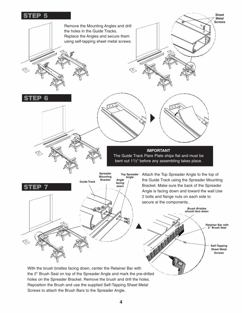
Remove the Mounting Angles and drillthe holes in the Guide Tracks.Replace the Angles and secure themusing self-tapping sheet metal screws.
IMPORTANTThe Guide Track Flare Plate ships flat and must bebent out 11/2” before any assembling takes place.
Guide Track
Top SpreaderAngle
Anglefacingdown
SpreaderMountingBracket
Retainer Bar with2'' Brush Seal
Brush Bristlesshould face down
Self-TappingSheet Metal
Screws
Attach the Top Spreader Angle to the top ofthe Guide Track using the Spreader MountingBracket. Make sure the back of the SpreaderAngle is facing down and toward the wall.Use2 bolts and flange nuts on each side tosecure al the components..
With the brush bristles facing down, center the Retainer Bar with the 2'' Brush Seal on top of the Spreader Angle and mark the pre-drilledholes on the Spreader Bracket. Remove the brush and drill the holes.Reposition the Brush and use the supplied Self-Tapping Sheet MetalScrews to attach the Brush Bars to the Spreader Angle.
SheetMetal
Screws

5
STEP 8
STEP 9
Attach a Drum Mounting Plate tothe top of each Track Guide using5/16'' x 1-1/4'' bolts with flangenuts. The “C” Bracket (motor side)goes on the left and the roundcradle (bearing side) is on theright, unless ordered otherwise.
IMPORTANT: Use the bottomhole of each set of holes.
Bottom Hole(Set 1)
Bottom Hole(Set 2)
Drum MountingPlate with “C” Bracket
(Motor Side)
Drum Mounting Plate(Bearing Side)
Place the assembly into the doorwayopening. The bottom of each GuideTrack should be resting on the floor.The front edge of the Drum MountingPlates should be flush with the frontedge of the door jamb tight againstthe header. Make sure the assemblyis plumb. Mark the 4 mounting holeson each of the jamb.
Remove the assembly and drill the holes. If thejamb is wood, a lag screw with washer is allthat is needed. If the jamb is concrete or steel& concrete, a wall anchor should be placed ineach hole.
Stand the assembled unit upright and lean it against awall. Place the Screen Roller Drum into each DrumMounting Plate.
The In-Tube Motor should be to the left and theBushing/Bearing to the right unless ordered differently.
STEP 10
GuideTrack
WARNINGDO NOT remove the Roll Ties until
the Roll Tube is secured to both DrumMounting Plates.
Bushing/Bearing
Screen onRoller Drum
In-TubeMotor
Roll Ties
Front edge ofDrum Mounting Plate
flush withfront edge of
door jambtight againstthe header
STEP 11 In-TubeMotor
Bushing/Bearing

6
STEP 12
Bottom Edgeof Screen
facing down
RoundCradle
The Bottom Edge of the Screen facing down.
STEP 13Reposition the assembly in the doorwayopening and fasten it securely againstthe jambs with lag screws and washers.
“C” Bracket
Pin Clip
NylonBushing
MotorHead
With the LimitAdjustment Screwsfacing outward,place the nylonbushing over thebottom pin.
Insert theMotor Headinto the“C” Bracket.
Place the Pin Clipunder the Bracket Lipand around the top pin.
LimitAdjustmentScrews
Then carefully cut the Roll Ties without cutting the screen. Slip the bot-tom edge of the screen into the Guide Tracks. Place the leading edgein front of the Rubber Gasket to create a seal.
Bottom Edgeof Screen
RubberGasket

STEP 15
7
Exterior of DoorwayOpening
GuideTrack
GuideTrack
Self-TappingScrews
Self-TappingScrews
After all adjustments are made the Rear Spreader Platecan be attached. It is fastened to the back (exterior) of theGuide Tracks. Use 4 self-tapping screws.
STEP 14Rear Spreader Plate
Next, the motor should be connected to a120 v, 60hz power source. The location of theUp/ Down Switch is up to the installer but itshould be convenient for the operator. Followthe wiring diagram to the right.
Rear Vinyl Cover
1. Rear Vinyl Cover will attach behindthe screen barrel when standing inside thebuilding looking out.
2. Mount aluminum angle to header andthen attach vinyl flap using the hook/loopprovided.
3. If you ordered the Aluminum Rear Spreaderupgrade, then you will only need the 4 tek screwsto fasten the Aluminum Spreader to the back sideof the guide tracks.
RED
BLACK
Direction 1
Direction 2
WHITE
GREEN
Neutral
Ground
WHITENeutral
GREENGround
BLACK120v - 60hz
IMPORTANT
All electrical work should be performed inaccordance with local and state buildingcodes. If you are in doubt of proper wiringinstallation, we recommend acquiring theservices of a certi�ed electrician.
From theWall
Up/Down Switch
Motor
STEP 16 – NOTE –
Some models have themotor on the right but thelimit adjustment screwcon�guration and graphicsare the same as the morecommon left motor positioning.
Down LimitAdjustment Screw
Up LimitAdjustment Screw
Set the up limit and the down limit. Use the suppliedBlack Plastic Tool to set the limits.Note: The screw on top sets the “Down/Lower” limit.The switch on the bottom sets the “Up/Top” limit.Material should roll off the back side of barreltowards the outside or exterior of the building.Important: The large arrows on the far left of thedrum by the limit adjustment screws refer to thedrum rotation.
A. It is important to note that the arrows by the limit adjustment screw refer to thedrum rotation. The door panel comes off the tube on the back side and thelimit adjustment faces the front of the door assembly.
B. Turning an adjustment screw clockwise will increase the maximum travel inthe direction that it controls, and turning it counterclockwise will decrease themaximum travel.
C. To set a limit, run the motor in the selected direction.
ScreenBarrel
Screen
Door Jamb
Aluminum Angle
Vinyl Flap(attach to angle
with hook and loop)
(OUTSIDEOF THE
BUILDING)
SIDE VIEW OFSCREEN BARREL & DOOR OPENING

NOTES
D. If the motor stops on its own before reaching the desired stop, turn the appropriate limit screw positive (clockwise). Every 3-4 turns of the limit adjustment screw equals approximately 1” of screen travel. Afterturning the limit adjustment screw, use the control switch to move the motor to the new limit position.NOTE: If the motor does not stop on its own before reaching the desired limit, go to Step F.
E. When you are approximately at the desired limit position, use the control switch to run the motor awayfrom the limit, 2’ to 3’ and then back.This will allow you to see precisely where the limits are set. Makesmall adjustments if required.
F. If the motor does not stop on its own at least 6” before the desired limit position, stop the motor with thecontrol switch. Then turn the adjustment screw counterclockwise (negative) direction. Confirm that themotor is at the limit and set the limit as per Steps D & E. If the motor has not stopped at the limit, continueturning the screw counterclockwise (up to 120 turns may be needed).
NOTE: The motor has a built in thermal cut-off. If after several minutes of use the motor will not run in eitherdirection, allow the motor to cool for approximately 20 minutes before using again.
STEP 16 continued
800-888-9750TMI, LLC • 5350 Campbells Run Road • Pittsburgh, PA 15205-9738 • 412.787.9750
Fax: 412.787.3665 • Web Site: www.tmi-pvc.com • E-Mail: [email protected] © 2011 TMI, LLC
Catalog No. II-TMI-SP-RUD-IJ-M 07-11