altablue™ touch series adhesive melters -...
TRANSCRIPT

AltaBlue™ Touch Series Adhesive Melters
Customer Product ManualPart 1120350_04
Issued 3/14
NORDSON CORPORATION DULUTH, GEORGIA USAwww.nordson.com
This document contains important safety informationBe sure to read and follow all safety information in thisdocument and any other related documentation.

Part 1120350_04 � 2014 Nordson CorporationAll rights reserved
Nordson Corporation welcomes requests for information, comments, and inquiries about its products. General informationabout Nordson can be found on the Internet using the following address: http://www.nordson.com.
Address all correspondence to:
Nordson CorporationAttn: Customer Service11475 Lakefield Drive
Duluth, GA 30097
Notice
This is a Nordson Corporation publication which is protected by copyright. Original copyright date 2011.No�part�of�this�document may be photocopied, reproduced, or translated to another language without the prior written
consent of Nordson�Corporation. The�information�contained in this publication is subject to change without notice.
Trademarks
AccuJet, AeroCharge, Apogee, AquaGuard, Asymtek, Automove, Baitgun, Blue Box, Bowtie, CanWorks, Century, CF, CleanSleeve, CleanSpray, ColorMax,Color‐on‐Demand, Control�Coat, Coolwave, Cross‐Cut, cScan+, Dage, Dispensejet, DispenseMate, DuraBlue, DuraDrum, Durafiber, DuraPail, Dura‐Screen,Durasystem, Easy�Coat, Easymove Plus, Ecodry, Econo‐Coat, e.DOT, EFD, Emerald, Encore, ESP, e stylized, ETI ‐ stylized, Excel 2000, Fibrijet, Fillmaster,
FlexiCoat, Flex‐O‐Coat, Flow Sentry, Fluidmove, FoamMelt, FoamMix, Fulfill, GreenUV, HDLV, Heli‐flow, Horizon, Hot Shot, iControl, iDry, iFlow, Isocoil,Isocore, Iso‐Flo, iTRAX, Kinetix, LEAN�CELL, Little�Squirt, LogiComm, Magnastatic, March, Maverick, MEG, Meltex, Microcoat, Micromark, Micromedics,
MicroSet, Millennium, Mini Squirt, Mountaingate, Nordson, Optimum, Package of Values, Pattern View, PermaFlo, PicoDot, Porous�Coat, PowderGrid,Powderware, Precisecoat, PRIMARC, Printplus, Prism, ProBlue, Prodigy, Pro‐Flo, ProLink, Pro‐Meter, Pro‐Stream, RBX, Rhino, Saturn, Saturn with rings,Scoreguard, Seal Sentry, Select�Charge, Select�Coat, Select Cure, Signature, Slautterback, Smart‐Coat, Solder Plus, Spectrum, Speed‐Coat, SureBead,
Sure Coat, Sure‐Max, Sure Wrap, Tracking�Plus, TRAK, Trends, Tribomatic, TrueBlue, TrueCoat, Ultra, UpTime, u‐TAH, Vantage, VersaBlue, Versa‐Coat,VersaDrum, VersaPail, Versa‐Screen, Versa‐Spray, Watermark, and When you expect more. are registered trademarks of Nordson Corporation.
Accubar, Active Nozzle, Advanced Plasma Systems, AeroDeck, AeroWash, AltaBlue, AltaSlot, Alta Spray, Artiste, ATS, Auto‐Flo, AutoScan, Axiom, Best Choice, Blue Series, Bravura, CanPro, Champion, Check Mate, ClassicBlue, Classic IX, Clean�Coat, Cobalt, Controlled Fiberization, Control�Weave,
ContourCoat, CPX, cSelect, Cyclo‐Kinetic, DispensLink, Dry Cure, DuraBraid, DuraCoat, DuraPUR, Easy Clean, EasyOn, EasyPW, Eclipse, e.dot+,E‐Nordson, Equalizer, EquiBead, FillEasy, Fill�Sentry, Flow Coat, Fluxplus, Get Green With Blue, G‐Net, G‐Site, IntelliJet, iON, Iso‐Flex, iTrend,
Lacquer Cure, Maxima, Mesa, MicroFin, MicroMax, Mikros, MiniBlue, MiniEdge, Minimeter, Multifill, MultiScan, Myritex, Nano, NexJet, OmniScan, OptiMix,OptiStroke, Partnership+Plus, PatternJet, PatternPro, PCI, Pinnacle, Plasmod, Powder�Pilot, Powder Port, Powercure, Process Sentry, Pulse Spray,
PURBlue, PURJet, Ready Coat, RediCoat, Royal Blue, Select�Series, Sensomatic, Shaftshield, SheetAire, Smart, Smartfil, SolidBlue, Spectral, SpeedKing,Spray Works, Summit, SureFoam, Sure�Mix, SureSeal, Swirl�Coat, TAH, ThruWave, Trade�Plus, Trilogy, Ultra FoamMix, UltraMax, Ultrasaver, Ultrasmart,
Universal, ValueMate, Versa, Vista, Web Cure, YESTECH, and 2�Rings (Design) are�trademarks of Nordson�Corporation.
Designations and trademarks stated in this document may be brands that, when used by third parties for their own purposes, could lead to violation of the owners' rights.

Table of Contents i
Part 1120350_04� 2014 Nordson Corporation
Safety 1-1. . . . . . . . . . . . . . . . . . . . . . . . . . . . . . . . . . . . . . . . . . . . . . . . . . . . .Safety Alert Symbols 1‐1. . . . . . . . . . . . . . . . . . . . . . . . . . . . . . . . . . . . . . . .Responsibilities of the Equipment Owner 1‐2. . . . . . . . . . . . . . . . . . . . . . .
Safety Information 1‐2. . . . . . . . . . . . . . . . . . . . . . . . . . . . . . . . . . . . . . . .Instructions, Requirements, and Standards 1‐2. . . . . . . . . . . . . . . . . .User Qualifications 1‐3. . . . . . . . . . . . . . . . . . . . . . . . . . . . . . . . . . . . . . .
Applicable Industry Safety Practices 1‐3. . . . . . . . . . . . . . . . . . . . . . . . . .Intended Use of the Equipment 1‐3. . . . . . . . . . . . . . . . . . . . . . . . . . . . .Instructions and Safety Messages 1‐4. . . . . . . . . . . . . . . . . . . . . . . . . .Installation Practices 1‐4. . . . . . . . . . . . . . . . . . . . . . . . . . . . . . . . . . . . . .Operating Practices 1‐4. . . . . . . . . . . . . . . . . . . . . . . . . . . . . . . . . . . . . .Maintenance and Repair Practices 1‐5. . . . . . . . . . . . . . . . . . . . . . . . .
Equipment Safety Information 1‐5. . . . . . . . . . . . . . . . . . . . . . . . . . . . . . . .Equipment Shutdown 1‐6. . . . . . . . . . . . . . . . . . . . . . . . . . . . . . . . . . . . .
Relieving System Hydraulic Pressure 1‐6. . . . . . . . . . . . . . . . . . . . .De‐energizing the System 1‐6. . . . . . . . . . . . . . . . . . . . . . . . . . . . . . .Disabling the Applicators 1‐6. . . . . . . . . . . . . . . . . . . . . . . . . . . . . . . .
General Safety Warnings and Cautions 1‐7. . . . . . . . . . . . . . . . . . . . . .Other Safety Precautions 1‐10. . . . . . . . . . . . . . . . . . . . . . . . . . . . . . . . . .First Aid 1‐10. . . . . . . . . . . . . . . . . . . . . . . . . . . . . . . . . . . . . . . . . . . . . . . . .
Safety Labels and Tags 1‐11. . . . . . . . . . . . . . . . . . . . . . . . . . . . . . . . . . . . .
Introduction 2-1. . . . . . . . . . . . . . . . . . . . . . . . . . . . . . . . . . . . . . . . . . . . . . .Intended Use 2‐1. . . . . . . . . . . . . . . . . . . . . . . . . . . . . . . . . . . . . . . . . . . . . .
Electromagnetic Compatibility (EMC) 2‐1. . . . . . . . . . . . . . . . . . . . . . .Examples of Unintended Use 2‐2. . . . . . . . . . . . . . . . . . . . . . . . . . . . . .
Residual Risks 2‐2. . . . . . . . . . . . . . . . . . . . . . . . . . . . . . . . . . . . . . . . . . . . .Key Components 2‐3. . . . . . . . . . . . . . . . . . . . . . . . . . . . . . . . . . . . . . . . . . .
Electrical Components 2‐4. . . . . . . . . . . . . . . . . . . . . . . . . . . . . . . . . . . .Pump Shut-Off Valve 2‐5. . . . . . . . . . . . . . . . . . . . . . . . . . . . . . . . . . . . .Pressure Control Valves 2‐5. . . . . . . . . . . . . . . . . . . . . . . . . . . . . . . . . .
Modes of Operation 2‐6. . . . . . . . . . . . . . . . . . . . . . . . . . . . . . . . . . . . . . . . .Heating and Heaters Off (Normal Mode) 2‐6. . . . . . . . . . . . . . . . . . . . .Standby 2‐6. . . . . . . . . . . . . . . . . . . . . . . . . . . . . . . . . . . . . . . . . . . . . . . .Fault 2‐6. . . . . . . . . . . . . . . . . . . . . . . . . . . . . . . . . . . . . . . . . . . . . . . . . . .
Gear‐to‐Line Capability 2‐6. . . . . . . . . . . . . . . . . . . . . . . . . . . . . . . . . . . . . .Melter Identification 2‐7. . . . . . . . . . . . . . . . . . . . . . . . . . . . . . . . . . . . . . . . .
Hardware Installation and Setup 3-1. . . . . . . . . . . . . . . . . . . . . . . . . . . .Overview 3‐1. . . . . . . . . . . . . . . . . . . . . . . . . . . . . . . . . . . . . . . . . . . . . . . . . .
Additional Information 3‐1. . . . . . . . . . . . . . . . . . . . . . . . . . . . . . . . . . . . .Installation Tasks 3‐2. . . . . . . . . . . . . . . . . . . . . . . . . . . . . . . . . . . . . . . .Experience of Installation Personnel 3‐2. . . . . . . . . . . . . . . . . . . . . . . .
Installation Requirements 3‐2. . . . . . . . . . . . . . . . . . . . . . . . . . . . . . . . . . . .Clearances 3‐2. . . . . . . . . . . . . . . . . . . . . . . . . . . . . . . . . . . . . . . . . . . . . .Ventilation 3‐6. . . . . . . . . . . . . . . . . . . . . . . . . . . . . . . . . . . . . . . . . . . . . .Electrical Power 3‐6. . . . . . . . . . . . . . . . . . . . . . . . . . . . . . . . . . . . . . . . . .Pump Drive Internal Filter 3‐7. . . . . . . . . . . . . . . . . . . . . . . . . . . . . . . . . .Other Considerations 3‐7. . . . . . . . . . . . . . . . . . . . . . . . . . . . . . . . . . . . .
Unpacking the Melter 3‐8. . . . . . . . . . . . . . . . . . . . . . . . . . . . . . . . . . . . . . .Moving the Unpacked Melter 3‐8. . . . . . . . . . . . . . . . . . . . . . . . . . . . . .Contents of the Installation Kit 3‐8. . . . . . . . . . . . . . . . . . . . . . . . . . . . . .Customer‐Supplied Materials 3‐8. . . . . . . . . . . . . . . . . . . . . . . . . . . . . .
Configuring the Electrical Service 3‐9. . . . . . . . . . . . . . . . . . . . . . . . . . . . .Residual Current Circuit Breakers 3‐9. . . . . . . . . . . . . . . . . . . . . . . . . .Connecting the Electrical Service 3‐9. . . . . . . . . . . . . . . . . . . . . . . . . . .

Table of Contentsii
Part 1120350_04 � 2014 Nordson Corporation
Connecting Hoses and Applicators 3‐11. . . . . . . . . . . . . . . . . . . . . . . . . . . .Setting Up Inputs/Outputs 3‐17. . . . . . . . . . . . . . . . . . . . . . . . . . . . . . . . . . .Setting Up Gear‐to‐Line Operation 3‐22. . . . . . . . . . . . . . . . . . . . . . . . . . . .Connecting and Programming the Pump for Remote Control 3‐23. . . . . .
Wiring 3‐23. . . . . . . . . . . . . . . . . . . . . . . . . . . . . . . . . . . . . . . . . . . . . . . . . .Programming 3‐23. . . . . . . . . . . . . . . . . . . . . . . . . . . . . . . . . . . . . . . . . . . .
Installing Optional Equipment 3‐25. . . . . . . . . . . . . . . . . . . . . . . . . . . . . . . .Connecting an Applicator Driver, Pattern Controller, or Timer 3‐25. . . . .Flushing the Melter 3‐25. . . . . . . . . . . . . . . . . . . . . . . . . . . . . . . . . . . . . . . . .Disposing of Melter 3‐25. . . . . . . . . . . . . . . . . . . . . . . . . . . . . . . . . . . . . . . . .
About the Touch Screen Display and User Interface 4-1. . . . . . . . . .Overview 4‐1. . . . . . . . . . . . . . . . . . . . . . . . . . . . . . . . . . . . . . . . . . . . . . . . . .
Starting the Melter for the First Time 4‐2. . . . . . . . . . . . . . . . . . . . . . . .Navigating the Touch Screen Displays 4‐3. . . . . . . . . . . . . . . . . . . . . . . . .
About the Operator Display 4‐3. . . . . . . . . . . . . . . . . . . . . . . . . . . . . . . .Monitoring the Status of the Melter 4‐5. . . . . . . . . . . . . . . . . . . . . . . .
About the Master Controls Display 4‐8. . . . . . . . . . . . . . . . . . . . . . . . . .
Basic Operation and Melter Configuration 5-1. . . . . . . . . . . . . . . . . . .Overview 5‐1. . . . . . . . . . . . . . . . . . . . . . . . . . . . . . . . . . . . . . . . . . . . . . . . . .Operating the Melter 5‐2. . . . . . . . . . . . . . . . . . . . . . . . . . . . . . . . . . . . . . . .
Starting the Melter 5‐2. . . . . . . . . . . . . . . . . . . . . . . . . . . . . . . . . . . . . . . .Filling the Reservoir 5‐2. . . . . . . . . . . . . . . . . . . . . . . . . . . . . . . . . . . . . .
Controlling the Heaters, Standby and Scheduler 5‐3. . . . . . . . . . . . . . . . .Controlling the Pumps 5‐5. . . . . . . . . . . . . . . . . . . . . . . . . . . . . . . . . . . . . . .Understanding Zones 5‐6. . . . . . . . . . . . . . . . . . . . . . . . . . . . . . . . . . . . . . . .Configuring Zones 5‐9. . . . . . . . . . . . . . . . . . . . . . . . . . . . . . . . . . . . . . . . . .
Enabling and Disabling Zones 5‐10. . . . . . . . . . . . . . . . . . . . . . . . . . . . . .Modifying Zone Set Point Temperatures 5‐11. . . . . . . . . . . . . . . . . . . . .Modifying Zone Names 5‐12. . . . . . . . . . . . . . . . . . . . . . . . . . . . . . . . . . . .Modifying External Zone PID Types 5‐13. . . . . . . . . . . . . . . . . . . . . . . . .
Understanding Pumps 5‐14. . . . . . . . . . . . . . . . . . . . . . . . . . . . . . . . . . . . . . .Configuring Pumps 5‐17. . . . . . . . . . . . . . . . . . . . . . . . . . . . . . . . . . . . . . . . . .
Enabling and Disabling Pumps 5‐18. . . . . . . . . . . . . . . . . . . . . . . . . . . . .Changing Pump Operation Modes 5‐19. . . . . . . . . . . . . . . . . . . . . . . . . .Adjusting Pump Speed 5‐22. . . . . . . . . . . . . . . . . . . . . . . . . . . . . . . . . . . .Modifying Pump Names 5‐22. . . . . . . . . . . . . . . . . . . . . . . . . . . . . . . . . . .
Advanced Melter Configuration 6-1. . . . . . . . . . . . . . . . . . . . . . . . . . . . .Overview 6‐1. . . . . . . . . . . . . . . . . . . . . . . . . . . . . . . . . . . . . . . . . . . . . . . . . .Advanced Temperature Settings 6‐3. . . . . . . . . . . . . . . . . . . . . . . . . . . . . .
Accessing Temperature Settings 6‐3. . . . . . . . . . . . . . . . . . . . . . . . .Defining a Global Set Point Temperature 6‐4. . . . . . . . . . . . . . . . . . . . .Defining Temperature Limits 6‐6. . . . . . . . . . . . . . . . . . . . . . . . . . . . . . .Defining Ready Delay 6‐7. . . . . . . . . . . . . . . . . . . . . . . . . . . . . . . . . . . . .Defining Standby Settings 6‐8. . . . . . . . . . . . . . . . . . . . . . . . . . . . . . . . .
Automatic Standby 6‐9. . . . . . . . . . . . . . . . . . . . . . . . . . . . . . . . . . . . .Auto Exit Standby Time 6‐11. . . . . . . . . . . . . . . . . . . . . . . . . . . . . . . . .
Advanced Pump Settings 6‐12. . . . . . . . . . . . . . . . . . . . . . . . . . . . . . . . . . . .Accessing Pump Settings 6‐12. . . . . . . . . . . . . . . . . . . . . . . . . . . . . . .
Enabling and Disabling Auto Pump 6‐13. . . . . . . . . . . . . . . . . . . . . . . . . .Defining Pump Remote Control 6‐14. . . . . . . . . . . . . . . . . . . . . . . . . . . . .Calibrating Pumps 6‐15. . . . . . . . . . . . . . . . . . . . . . . . . . . . . . . . . . . . . . . .

Table of Contents iii
Part 1120350_04� 2014 Nordson Corporation
Advanced Input/Output Settings 6‐16. . . . . . . . . . . . . . . . . . . . . . . . . . . . . .System Settings 6‐18. . . . . . . . . . . . . . . . . . . . . . . . . . . . . . . . . . . . . . . . . . . .
Accessing System Settings 6‐18. . . . . . . . . . . . . . . . . . . . . . . . . . . . . .Defining Formats and Units 6‐19. . . . . . . . . . . . . . . . . . . . . . . . . . . . . . . .Defining the Date and Time 6‐20. . . . . . . . . . . . . . . . . . . . . . . . . . . . . . . .Defining Service Intervals 6‐21. . . . . . . . . . . . . . . . . . . . . . . . . . . . . . . . . .Defining Language Preference 6‐23. . . . . . . . . . . . . . . . . . . . . . . . . . . . .Defining Display Settings 6‐24. . . . . . . . . . . . . . . . . . . . . . . . . . . . . . . . . .
Configuring Password Protection 6‐26. . . . . . . . . . . . . . . . . . . . . . . . . . . . . .Configuring Scheduled Events 6‐28. . . . . . . . . . . . . . . . . . . . . . . . . . . . . . . .Administrative Options and Settings 6‐33. . . . . . . . . . . . . . . . . . . . . . . . . . .
Accessing Administration Settings and Options 6‐33. . . . . . . . . . . . .Upgrading Software and Firmware 6‐34. . . . . . . . . . . . . . . . . . . . . . . . . .
Reverting back to a Previous Version 6‐36. . . . . . . . . . . . . . . . . . . . . .Managing Recipes 6‐37. . . . . . . . . . . . . . . . . . . . . . . . . . . . . . . . . . . . . . . .Accessing the Recipes Screen 6‐37. . . . . . . . . . . . . . . . . . . . . . . . . . . . .
What's Being Saved in a Recipe 6‐39. . . . . . . . . . . . . . . . . . . . . . . . . .Viewing the Event Log - Save Diagnostics 6‐40. . . . . . . . . . . . . . . . . . . .Resetting to System Defaults 6‐42. . . . . . . . . . . . . . . . . . . . . . . . . . . . . . .Resetting Password Codes 6‐43. . . . . . . . . . . . . . . . . . . . . . . . . . . . . . . .Viewing Software Version and Heater On Hours 6‐44. . . . . . . . . . . . . .Locking Out Communications 6‐45. . . . . . . . . . . . . . . . . . . . . . . . . . . . . .Changing RTD Types 6‐46. . . . . . . . . . . . . . . . . . . . . . . . . . . . . . . . . . . . .
Default User Settings and Ranges 6‐47. . . . . . . . . . . . . . . . . . . . . . . . . . . . .
Service 7-1. . . . . . . . . . . . . . . . . . . . . . . . . . . . . . . . . . . . . . . . . . . . . . . . . . .Relieving System Pressure 7‐1. . . . . . . . . . . . . . . . . . . . . . . . . . . . . . . . . .
Through the Applicators 7‐1. . . . . . . . . . . . . . . . . . . . . . . . . . . . . . . . . . .Through the Melter Drain Valves 7‐2. . . . . . . . . . . . . . . . . . . . . . . . . . .
Preventive Maintenance Schedule 7‐3. . . . . . . . . . . . . . . . . . . . . . . . . . . .Locking Out the Motor Drives 7‐4. . . . . . . . . . . . . . . . . . . . . . . . . . . . . . . . .External Cleaning 7‐4. . . . . . . . . . . . . . . . . . . . . . . . . . . . . . . . . . . . . . . . . . .Changing the Material Type 7‐5. . . . . . . . . . . . . . . . . . . . . . . . . . . . . . . . . .Detaching the Exterior Panels 7‐5. . . . . . . . . . . . . . . . . . . . . . . . . . . . . . . .Fan and Air Filter 7‐5. . . . . . . . . . . . . . . . . . . . . . . . . . . . . . . . . . . . . . . . . . .Motor and Gear Box 7‐6. . . . . . . . . . . . . . . . . . . . . . . . . . . . . . . . . . . . . . . .
Changing the Motor Lubricant 7‐6. . . . . . . . . . . . . . . . . . . . . . . . . . . . . .Replacing a Motor or Coupling 7‐7. . . . . . . . . . . . . . . . . . . . . . . . . . . . .
Pump 7‐9. . . . . . . . . . . . . . . . . . . . . . . . . . . . . . . . . . . . . . . . . . . . . . . . . . . . .Tightening the Pump Screws 7‐9. . . . . . . . . . . . . . . . . . . . . . . . . . . . . . .Tightening the Pump Gland Bolt 7‐10. . . . . . . . . . . . . . . . . . . . . . . . . . . .Replacing a Pump 7‐11. . . . . . . . . . . . . . . . . . . . . . . . . . . . . . . . . . . . . . . .
Filter Cartridge 7‐15. . . . . . . . . . . . . . . . . . . . . . . . . . . . . . . . . . . . . . . . . . . . .Filter Service Kit 7‐16. . . . . . . . . . . . . . . . . . . . . . . . . . . . . . . . . . . . . . . . . . . .Pressure Control Valve 7‐17. . . . . . . . . . . . . . . . . . . . . . . . . . . . . . . . . . . . . .Pressure/Circulation Control Valve Service Kit 7‐18. . . . . . . . . . . . . . . . . .Cleaning the Tank 7‐19. . . . . . . . . . . . . . . . . . . . . . . . . . . . . . . . . . . . . . . . . .
Draining Material from the Tank 7‐19. . . . . . . . . . . . . . . . . . . . . . . . . . . .Cleaning the Tank by Hand 7‐19. . . . . . . . . . . . . . . . . . . . . . . . . . . . . . . .Tightening the Fixing Screws 7‐19. . . . . . . . . . . . . . . . . . . . . . . . . . . . . .

Table of Contentsiv
Part 1120350_04 � 2014 Nordson Corporation
Main PCA Board 7‐20. . . . . . . . . . . . . . . . . . . . . . . . . . . . . . . . . . . . . . . . . . .Maintenance Record Form 7‐23. . . . . . . . . . . . . . . . . . . . . . . . . . . . . . . . . . .
Troubleshooting 8-1. . . . . . . . . . . . . . . . . . . . . . . . . . . . . . . . . . . . . . . . . . .Safety 8‐1. . . . . . . . . . . . . . . . . . . . . . . . . . . . . . . . . . . . . . . . . . . . . . . . . . . . .Touch Screen Alerts and Faults 8‐2. . . . . . . . . . . . . . . . . . . . . . . . . . . . . .
About Touch Screen Messages 8‐2. . . . . . . . . . . . . . . . . . . . . . . . . . . .Pump and Zone Alerts/Faults 8‐2. . . . . . . . . . . . . . . . . . . . . . . . . . . .System Alerts 8‐3. . . . . . . . . . . . . . . . . . . . . . . . . . . . . . . . . . . . . . . . .System Faults 8‐4. . . . . . . . . . . . . . . . . . . . . . . . . . . . . . . . . . . . . . . . .
Motor Drive Faults 8‐5. . . . . . . . . . . . . . . . . . . . . . . . . . . . . . . . . . . . . . . . . .Troubleshooting Tables 8‐10. . . . . . . . . . . . . . . . . . . . . . . . . . . . . . . . . . . . .
Melter Not Functioning 8‐10. . . . . . . . . . . . . . . . . . . . . . . . . . . . . . . . . . . .One Channel (Heating Zone) Does Not Heat 8‐10. . . . . . . . . . . . . . . . .
Troubleshooting Pump 8‐11. . . . . . . . . . . . . . . . . . . . . . . . . . . . . . . . . . . . . .No Material (Pump Does not Rotate) 8‐11. . . . . . . . . . . . . . . . . . . . . . . .No Material (Motor Rotating) 8‐12. . . . . . . . . . . . . . . . . . . . . . . . . . . . . . .Too Little Material 8‐12. . . . . . . . . . . . . . . . . . . . . . . . . . . . . . . . . . . . . . . .Material Pressure Too High 8‐13. . . . . . . . . . . . . . . . . . . . . . . . . . . . . . . .Material Pressure Too Low 8‐13. . . . . . . . . . . . . . . . . . . . . . . . . . . . . . . .Material Residue in Tank 8‐14. . . . . . . . . . . . . . . . . . . . . . . . . . . . . . . . . .Material Hardens in Tank 8‐14. . . . . . . . . . . . . . . . . . . . . . . . . . . . . . . . . .Others 8‐14. . . . . . . . . . . . . . . . . . . . . . . . . . . . . . . . . . . . . . . . . . . . . . . . . .
Parts 9-1. . . . . . . . . . . . . . . . . . . . . . . . . . . . . . . . . . . . . . . . . . . . . . . . . . . . . .Using the Illustrated Parts List 9‐1. . . . . . . . . . . . . . . . . . . . . . . . . . . . . . . .AltaBlue Configuration Code 9‐2. . . . . . . . . . . . . . . . . . . . . . . . . . . . . . . . .Frame Assembly 9‐6. . . . . . . . . . . . . . . . . . . . . . . . . . . . . . . . . . . . . . . . . . .
One/Two‐Pump Melter Frame Parts 9‐6. . . . . . . . . . . . . . . . . . . . . . . .Three/Four‐Pump Melter Frame Parts 9‐8. . . . . . . . . . . . . . . . . . . . . . .
Reservoir/Manifold Assembly 9‐10. . . . . . . . . . . . . . . . . . . . . . . . . . . . . . . .One/Two‐Pump Melter Reservoir/Manifold Parts 9‐10. . . . . . . . . . . . . .Three/Four‐Pump Melter Reservoir/Manifold Parts 9‐12. . . . . . . . . . . .100L Melter Reservoir/Manifold Parts 9‐14. . . . . . . . . . . . . . . . . . . . . . .Manifold Parts 9‐16. . . . . . . . . . . . . . . . . . . . . . . . . . . . . . . . . . . . . . . . . . .
Hopper Assembly 9‐20. . . . . . . . . . . . . . . . . . . . . . . . . . . . . . . . . . . . . . . . . .One/Two‐Pump Melter Hopper Parts 9‐20. . . . . . . . . . . . . . . . . . . . . . . .Three/Four‐Pump Melter Hopper Parts 9‐24. . . . . . . . . . . . . . . . . . . . . .100L Melter Hopper Parts 9‐28. . . . . . . . . . . . . . . . . . . . . . . . . . . . . . . . .
Pump Assemblies 9‐30. . . . . . . . . . . . . . . . . . . . . . . . . . . . . . . . . . . . . . . . . .Pump Module Parts 9‐30. . . . . . . . . . . . . . . . . . . . . . . . . . . . . . . . . . . . . .Single‐Stream Pump Adapter Parts 9‐32. . . . . . . . . . . . . . . . . . . . . . . . .Dual‐Stream Pump Adapter Parts 9‐33. . . . . . . . . . . . . . . . . . . . . . . . . .Single‐Stream Gear Pumps 9‐34. . . . . . . . . . . . . . . . . . . . . . . . . . . . . . . .Dual‐Stream Gear Pumps 9‐37. . . . . . . . . . . . . . . . . . . . . . . . . . . . . . . . .Safety Valve Parts 9‐38. . . . . . . . . . . . . . . . . . . . . . . . . . . . . . . . . . . . . . .
Table of Contents v
Part 1120350_04� 2014 Nordson Corporation
Control Valve Assemblies 9‐40. . . . . . . . . . . . . . . . . . . . . . . . . . . . . . . . . . . .Control Valve Module Parts 9‐40. . . . . . . . . . . . . . . . . . . . . . . . . . . . . . . .Filter Cartridge Parts 9‐42. . . . . . . . . . . . . . . . . . . . . . . . . . . . . . . . . . . . . .Pressure Control Valve Parts 9‐43. . . . . . . . . . . . . . . . . . . . . . . . . . . . . .Pneumatic Pressure Control Valve Parts 9‐44. . . . . . . . . . . . . . . . . . . . .Pneumatic Pressure Control Valve Interface Parts 9‐46. . . . . . . . . . . .Manual Pneumatic Pressure Control Valve Parts 9‐48. . . . . . . . . . . . . .Flow Control Bypass Control Valve Parts 9‐50. . . . . . . . . . . . . . . . . . . .Manual Pneumatic Pressure Control Valve Cabinet 9‐52. . . . . . . . . . .Flow Control Bypass Control Valve Cabinet 9‐54. . . . . . . . . . . . . . . . . .Manual Pneumatic Pressure & Flow Control Bypass Control Valve InterfaceParts 9‐56. . . . . . . . . . . . . . . . . . . . . . . . . . . . . . . . . . . . . . . . . . . . . . . . . . . .Flow Control Bypass Control Valve Solenoid Parts 9‐57. . . . . . . . . . . .Manual Pneumatic Pressure & Flow Control Bypass Control Valve MultiConnector Parts 9‐58. . . . . . . . . . . . . . . . . . . . . . . . . . . . . . . . . . . . . . . . .Pressure Build Control Parts 9‐60. . . . . . . . . . . . . . . . . . . . . . . . . . . . . . .Circulation Control Valve Parts 9‐62. . . . . . . . . . . . . . . . . . . . . . . . . . . . .
Flow Control Bypass 9‐63. . . . . . . . . . . . . . . . . . . . . . . . . . . . . . . . . . .Schematics 9‐64. . . . . . . . . . . . . . . . . . . . . . . . . . . . . . . . . . . . . . . . . . . . .
Manual Pneumatic Pressure 9‐66. . . . . . . . . . . . . . . . . . . . . . . . . . . . .Motor Assembly 9‐67. . . . . . . . . . . . . . . . . . . . . . . . . . . . . . . . . . . . . . . . . . . .Electrical Enclosure Panel Assemblies 9‐68. . . . . . . . . . . . . . . . . . . . . . . . .
400V Melter Left Panel 9‐68. . . . . . . . . . . . . . . . . . . . . . . . . . . . . . . . . . . .One/Two‐Pump Melter 2 Hose/Gun (400V) Back Panel Parts (15, 30L) 9‐70. . . . . . . . . . . . . . . . . . . . . . . . . . . . . . . . . . . . . . . . . . . . . . .One/Two‐Pump Melter 2 Hose/Gun (400V) Back Panel Parts (50L) 9‐72. . . . . . . . . . . . . . . . . . . . . . . . . . . . . . . . . . . . . . . . . . . . . . . . . .One/Two‐Pump Melter 2 Back Panel Parts 9‐74. . . . . . . . . . . . . . . . . . .One/Two-pump Melter 4/6 Hose/Gun (400V) Back Panel Parts (15L, 30L) 9‐76. . . . . . . . . . . . . . . . . . . . . . . . . . . . . . . . . . . . . . . . . . . . . .One/Twopump Melter 4/6 Hose/Gun (400V) Back Panel Parts (50L) 9‐78. . . . . . . . . . . . . . . . . . . . . . . . . . . . . . . . . . . . . . . . . . . . . . . . . .Three/Fourpump 4/6 Hose/Gun (400V) Melter Back Panel Parts (30,50L) 9‐80. . . . . . . . . . . . . . . . . . . . . . . . . . . . . . . . . . . . . . . . . . . . . . .Three/Four‐Pump Eight Hose/Gun (400V) Melter Back Panel Parts (30,50L) 9‐82. . . . . . . . . . . . . . . . . . . . . . . . . . . . . . . . . . . . . . . . . . . . . . .Two Hose/Gun (400V) Melter Right Panel Parts 9‐84. . . . . . . . . . . . . .Four Hose/Gun(400V) Melter Right Panel Parts 9‐86. . . . . . . . . . . . . . .Six Hose/Gun (400V) Melter Right Panel Parts 9‐88. . . . . . . . . . . . . . .Eight Hose/Gun (400V) Melter Right Panel Parts 9‐90. . . . . . . . . . . . . .Two Hose/Gun (240V) Melter Right Panel Parts 9‐92. . . . . . . . . . . . . .Four Hose/Gun(240V) Melter Right Panel Parts 9‐96. . . . . . . . . . . . . . .Six Hose/Gun (240V) Melter Right Panel Parts 9‐100. . . . . . . . . . . . . . .Eight Hose/Gun (240V) Melter Right Panel Parts 9‐104. . . . . . . . . . . . . .One/Two‐Pump Melter Bottom Panel Parts 9‐106. . . . . . . . . . . . . . . . . .Three/Four‐Pump Melter Bottom Panel Parts 9‐107. . . . . . . . . . . . . . . . .

Table of Contentsvi
Part 1120350_04 � 2014 Nordson Corporation
Control Panel Assembly 9‐108. . . . . . . . . . . . . . . . . . . . . . . . . . . . . . . . . . . . .Sensor Assembly 9‐110. . . . . . . . . . . . . . . . . . . . . . . . . . . . . . . . . . . . . . . . . . .Low Level Assembly 9‐112. . . . . . . . . . . . . . . . . . . . . . . . . . . . . . . . . . . . . . . .Optional Accessories 9‐113. . . . . . . . . . . . . . . . . . . . . . . . . . . . . . . . . . . . . . .
Pressure Indication 9‐113. . . . . . . . . . . . . . . . . . . . . . . . . . . . . . . . . . . . . . .Pneumatic Pressure Control Valve 9‐113. . . . . . . . . . . . . . . . . . . . . . . . . .Line‐Speed Signal Generator 9‐114. . . . . . . . . . . . . . . . . . . . . . . . . . . . . .Optional Fittings 9‐114. . . . . . . . . . . . . . . . . . . . . . . . . . . . . . . . . . . . . . . . .
Recommended Spare Parts 9‐115. . . . . . . . . . . . . . . . . . . . . . . . . . . . . . . . . .
Technical Data 10-1. . . . . . . . . . . . . . . . . . . . . . . . . . . . . . . . . . . . . . . . . . . . .General Data 10‐1. . . . . . . . . . . . . . . . . . . . . . . . . . . . . . . . . . . . . . . . . . . . . .Temperatures 10‐1. . . . . . . . . . . . . . . . . . . . . . . . . . . . . . . . . . . . . . . . . . . . . .Electrical Data 10‐2. . . . . . . . . . . . . . . . . . . . . . . . . . . . . . . . . . . . . . . . . . . . .Mechanical Data 10‐4. . . . . . . . . . . . . . . . . . . . . . . . . . . . . . . . . . . . . . . . . . .
One/Two and Three/Four Pump Melters 10‐4. . . . . . . . . . . . . . . . . . . . .Electrical Schematics 10‐5. . . . . . . . . . . . . . . . . . . . . . . . . . . . . . . . . . . . . . .Hydraulic Schematic 10‐6. . . . . . . . . . . . . . . . . . . . . . . . . . . . . . . . . . . . . . . .
Calculating Melter Power Requirements (Including Heater Specifications) A-1. . . . . . . . . . . . . . . . . . . . . . . . . . . . . . . . . . . . .

Safety 1-1
� 2014 Nordson Corporation Issued 10-11
Section 1Safety
Read this section before using the equipment. This section containsrecommendations and practices applicable to the safe installation, operation,and maintenance (hereafter referred to as “use”) of the product described inthis document (hereafter referred to as “equipment”). Additional safetyinformation, in the form of task‐specific safety alert messages, appears asappropriate throughout this document.
WARNING! Failure to follow the safety messages, recommendations, andhazard avoidance procedures provided in this document can result inpersonal injury, including death, or damage to equipment or property.
Safety Alert SymbolsThe following safety alert symbol and signal words are used throughout thisdocument to alert the reader to personal safety hazards or to identifyconditions that may result in damage to equipment or property. Comply withall safety information that follows the signal word.
WARNING! Indicates a potentially hazardous situation that, if not avoided,can result in serious personal injury, including death.
CAUTION! Indicates a potentially hazardous situation that, if not avoided,can result in minor or moderate personal injury.
CAUTION! (Used without the safety alert symbol) Indicates a potentiallyhazardous situation that, if not avoided, can result in damage to equipment orproperty.

Safety1-2
� 2014 Nordson CorporationIssued 10−11
Responsibilities of the Equipment Owner Equipment owners are responsible for managing safety information, ensuringthat all instructions and regulatory requirements for use of the equipment aremet, and for qualifying all potential users.
Safety Information � Research and evaluate safety information from all applicable sources,
including the owner‐specific safety policy, best industry practices,governing regulations, material manufacturer's product information, andthis document.
� Make safety information available to equipment users in accordance with
governing regulations. Contact the authority having jurisdiction forinformation.
� Maintain safety information, including the safety labels affixed to the
equipment, in readable condition.
Instructions, Requirements, and Standards � Ensure that the equipment is used in accordance with the information
provided in this document, governing codes and regulations, and bestindustry practices.
� If applicable, receive approval from your facility's engineering or safety
department, or other similar function within your organization, beforeinstalling or operating the equipment for the first time.
� Provide appropriate emergency and first aid equipment.
� Conduct safety inspections to ensure required practices are being
followed.
� Re‐evaluate safety practices and procedures whenever changes are
made to the process or equipment.

Safety 1-3
� 2014 Nordson Corporation Issued 10-11
User Qualifications
Equipment owners are responsible for ensuring that users:
� receive safety training appropriate to their job function as directed by
governing regulations and best industry practices
� are familiar with the equipment owner's safety and accident
prevention policies and procedures
� receive equipment‐ and task‐specific training from another qualified
individual
NOTE: Nordson can provide equipment‐specific installation,operation, and maintenance training. Contact your Nordsonrepresentative for information
� possess industry‐ and trade‐specific skills and a level of experience
appropriate to their job function
� are physically capable of performing their job function and are not
under the influence of any substance that degrades their mentalcapacity or physical capabilities
Applicable Industry Safety Practices The following safety practices apply to the use of the equipment in themanner described in this document. The information provided here is notmeant to include all possible safety practices, but represents the best safetypractices for equipment of similar hazard potential used in similar industries.
Intended Use of the Equipment � Use the equipment only for the purposes described and within the limits
specified in this document.
� Do not modify the equipment.
� Do not use incompatible materials or unapproved auxiliary devices.
Contact your Nordson representative if you have any questions onmaterial compatibility or the use of non‐standard auxiliary devices.
Safety1-4
� 2014 Nordson CorporationIssued 10−11
Instructions and Safety Messages � Read and follow the instructions provided in this document and other
referenced documents.
� Familiarize yourself with the location and meaning of the safety warning
labels and tags affixed to the equipment. Refer to Safety Labels and Tagsat the end of this section.
� If you are unsure of how to use the equipment, contact your Nordson
representative for assistance.
Installation Practices � Install the equipment in accordance with the instructions provided in this
document and in the documentation provided with auxiliary devices.
� Ensure that the equipment is rated for the environment in which it will be
used. This equipment has not been certified for compliance with theATEX directive nor as nonincendive and should not be installed inpotentially explosive environments.
� Ensure that the processing characteristics of the material will not create a
hazardous environment. Refer to the Material Safety Data Sheet (MSDS)for the material.
� If the required installation configuration does not match the installation
instructions, contact your Nordson representative for assistance.
� Position the equipment for safe operation. Observe the requirements for
clearance between the equipment and other objects.
� Install lockable power disconnects to isolate the equipment and all
independently powered auxiliary devices from their power sources.
� Properly ground all equipment. Contact your local building code
enforcement agency for specific requirements.
� Ensure that fuses of the correct type and rating are installed in fused
equipment.
� Contact the authority having jurisdiction to determine the requirement for
installation permits or inspections.
Operating Practices � Familiarize yourself with the location and operation of all safety devices
and indicators.
� Confirm that the equipment, including all safety devices (guards,
interlocks, etc.), is in good working order and that the requiredenvironmental conditions exist.
� Use the personal protective equipment (PPE) specified for each task.
Refer to Equipment Safety Information or the material manufacturer'sinstructions and MSDS for PPE requirements.
� Do not use equipment that is malfunctioning or shows signs of a potential
malfunction.

Safety 1-5
� 2014 Nordson Corporation Issued 10-11
Maintenance and Repair Practices � Allow only personnel with appropriate training and experience to operate
or service the equipment.
� Perform scheduled maintenance activities at the intervals described in
this document.
� Relieve system hydraulic and pneumatic pressure before servicing the
equipment.
� De‐energize the equipment and all auxiliary devices before servicing the
equipment.
� Use only new Nordson‐authorized refurbished or replacement parts.
� Read and comply with the manufacturer's instructions and the MSDS
supplied with equipment cleaning compounds.
NOTE: MSDSs for cleaning compounds that are sold by Nordson areavailable at www.nordson.com or by calling your Nordson representative.
� Confirm the correct operation of all safety devices before placing the
equipment back into operation.
� Dispose of waste cleaning compounds and residual process materials
according to governing regulations. Refer to the applicable MSDS orcontact the authority having jurisdiction for information.
� Keep equipment safety warning labels clean. Replace worn or damaged
labels.
Equipment Safety Information This equipment safety information is applicable to the following types ofNordson equipment:
� hot melt and cold adhesive application equipment and all related
accessories
� pattern controllers, timers, detection and verification systems, and all
other optional process control devices

Safety1-6
� 2014 Nordson CorporationIssued 10−11
Equipment Shutdown
To safely complete many of the procedures described in this document, theequipment must first be shut down. The level of shut down required varies bythe type of equipment in use and the procedure being completed. If required, shut down instructions are specified at the start of the procedure.The levels of shut down are:
Relieving System Hydraulic Pressure
Completely relieve system hydraulic pressure before breaking any hydraulicconnection or seal. Refer to the melter‐specific product manual forinstructions on relieving system hydraulic pressure.
De‐energizing the System
Isolate the system (melter, hoses, applicators, and optional devices) from allpower sources before accessing any unprotected high‐voltage wiring orconnection point.
1. Turn off the equipment and all auxiliary devices connected to theequipment (system).
2. To prevent the equipment from being accidentally energized, lock andtag the disconnect switch(es) or circuit breaker(s) that provide inputelectrical power to the equipment and optional devices.
NOTE: Government regulations and industry standards dictate specificrequirements for the isolation of hazardous energy sources. Refer to theappropriate regulation or standard.
Disabling the Applicators
NOTE: Adhesive dispensing applicators are referred to as “guns” in someprevious publications.
All electrical or mechanical devices that provide an activation signal to theapplicators, applicator solenoid valve(s), or the melter pump must bedisabled before work can be performed on or around an applicator that isconnected to a pressurized system.
1. Turn off or disconnect the applicator triggering device (pattern controller,timer, PLC, etc.).
2. Disconnect the input signal wiring to the applicator solenoid valve(s).
3. Reduce the air pressure to the applicator solenoid valve(s) to zero; thenrelieve the residual air pressure between the regulator and the applicator.

Safety 1-7
� 2014 Nordson Corporation Issued 10-11
General Safety Warnings and Cautions
Table 1‐1 contains the general safety warnings and cautions that apply toNordson hot melt and cold adhesive equipment. Review the table andcarefully read all of the warnings or cautions that apply to the type ofequipment described in this manual.
Equipment types are designated in Table 1-1 as follows:
HM = Hot melt (melters, hoses, applicators, etc.)
PC = Process control
CA = Cold adhesive (dispensing pumps, pressurized container, andapplicators)
Table 1‐1General Safety Warnings and Cautions
EquipmentType Warning or Caution
HM
WARNING! Hazardous vapors! Before processing any polyurethanereactive (PUR) hot melt or solvent‐based material through a compatibleNordson melter, read and comply with the material's MSDS. Ensurethat the material's processing temperature and flashpoints will not beexceeded and that all requirements for safe handling, ventilation, firstaid, and personal protective equipment are met. Failure to comply withMSDS requirements can cause personal injury, including death.
HM
WARNING! Reactive material! Never clean any aluminum componentor flush Nordson equipment with halogenated hydrocarbon fluids.Nordson melters and applicators contain aluminum components thatmay react violently with halogenated hydrocarbons. The use ofhalogenated hydrocarbon compounds in Nordson equipment cancause personal injury, including death.
HM, CAWARNING! System pressurized! Relieve system hydraulic pressurebefore breaking any hydraulic connection or seal. Failure to relieve thesystem hydraulic pressure can result in the uncontrolled release of hotmelt or cold adhesive, causing personal injury.
Continued...

Safety1-8
� 2014 Nordson CorporationIssued 10−11
Table 1‐1General Safety Warnings and Cautions (contd)
EquipmentType Warning or Caution
HMWARNING! Molten material! Wear eye or face protection, clothing thatprotects exposed skin, and heat‐protective gloves when servicingequipment that contains molten hot melt. Even when solidified, hot meltcan still cause burns. Failure to wear appropriate personal protectiveequipment can result in personal injury.
HM, PC
WARNING! Equipment starts automatically! Remote triggering devicesare used to control automatic hot melt applicators. Before working onor near an operating applicator, disable the applicator's triggeringdevice and remove the air supply to the applicator's solenoid valve(s).Failure to disable the applicator's triggering device and remove thesupply of air to the solenoid valve(s) can result in personal injury.
HM, CA, PC
WARNING! Risk of electrocution! Even when switched off andelectrically isolated at the disconnect switch or circuit breaker, theequipment may still be connected to energized auxiliary devices.De‐energize and electrically isolate all auxiliary devices beforeservicing the equipment. Failure to properly isolate electrical power toauxiliary equipment before servicing the equipment can result inpersonal injury, including death.
HM, CA, PC
WARNING! Risk of fire or explosion! Nordson adhesive equipment isnot rated for use in explosive environments and has not been cerfifiedfor the ATEX directive or as nonincendive. In addition, this equipmentshould not be used with solvent‐based adhesives that can create anexplosive atmosphere when processed. Refer to the MSDS for theadhesive to determine its processing characteristics and limitations.The use of incompatible solvent‐based adhesives or the improperprocessing of solvent‐based adhesives can result in personal injury,including death.
HM, CA, PCWARNING! Allow only personnel with appropriate training andexperience to operate or service the equipment. The use of untrainedor inexperienced personnel to operate or service the equipment canresult in injury, including death, to themselves and others and candamage to the equipment.

Safety 1-9
� 2014 Nordson Corporation Issued 10-11
Warning or CautionEquipment
Type
HMCAUTION! Hot surfaces! Avoid contact with the hot metal surfaces ofapplicators, hoses, and certain components of the melter. If contactcan not be avoided, wear heat‐protective gloves and clothing whenworking around heated equipment. Failure to avoid contact with hotmetal surfaces can result in personal injury.
HM
CAUTION! Some Nordson melters are specifically designed toprocess polyurethane reactive (PUR) hot melt. Attempting to processPUR in equipment not specifically designed for this purpose candamage the equipment and cause premature reaction of the hot melt. Ifyou are unsure of the equipment's ability to process PUR, contact yourNordson representative for assistance.
HM, CA
CAUTION! Before using any cleaning or flushing compound on or inthe equipment, read and comply with the manufacturer's instructionsand the MSDS supplied with the compound. Some cleaningcompounds can react unpredictably with hot melt or cold adhesive,resulting in damage to the equipment.
HM
CAUTION! Nordson hot melt equipment is factory tested with NordsonType R fluid that contains polyester adipate plasticizer. Certain hot meltmaterials can react with Type R fluid and form a solid gum that canclog the equipment. Before using the equipment, confirm that the hotmelt is compatible with Type R fluid.

Safety1-10
� 2014 Nordson CorporationIssued 10−11
Other Safety Precautions � Do not use an open flame to heat hot melt system components.
� Check high pressure hoses daily for signs of excessive wear, damage, or
leaks.
� Never point a dispensing handgun at yourself or others.
� Suspend dispensing handguns by their proper suspension point.
First Aid
If molten hot melt comes in contact with your skin:
1. Do NOT attempt to remove the molten hot melt from your skin.
2. Immediately soak the affected area in clean, cold water until the hot melthas cooled.
3. Do NOT attempt to remove the solidified hot melt from your skin.
4. In case of severe burns, treat for shock.
5. Seek expert medical attention immediately. Give the MSDS for the hotmelt to the medical personnel providing treatment.

Safety 1-11
� 2014 Nordson Corporation Issued 10-11
Safety Labels and Tags Figure 1‐1 illustrates the location of the product safety labels and tags affixedto the equipment. Table 1‐2 provides an illustration of the hazardidentification symbols that appear on each safety label and tag, the meaningof the symbol, or the exact wording of any safety message.
Figure 1‐1 Safety labels and tags

Safety1-12
� 2014 Nordson CorporationIssued 10−11
Safety Labels and Tags (contd)
Table 1‐2Safety Labels and Tags
Item Part Description
1. 1025795
WARNING! Hazardous voltage! Disconnect all power supplyconnections before servicing.
2. 224906 WARNING: TAG,WARNING,ELEC SHOCK
3. 224905 WARNING: HOT
4. 1100254 CAUTION: HOT SURFACE
5. 1100256 WARNING: TAG,WARNING,HOT ADH/HYD PRESS
6. 1120127 WARNING: TAG,WARNING,HIGH LEAKAGE CURRENT

Introduction 2-1
Part 1120350_04� 2014 Nordson Corporation
Section 2
Introduction
Intended Use AltaBlue™ adhesive melters may be used only to melt and convey suitablematerials, e.g. thermoplastic hot melt adhesives.
Any other use is considered to be unintended. Nordson will not be liable forpersonal injury or property damage resulting from unintended use.
Intended use includes the observance of Nordson safety instructions.Nordson recommends obtaining detailed information on the materials to beused.
Electromagnetic Compatibility (EMC)
In regard to electromagnetic compatibility (EMC), the melter is intended foruse in industrial applications.
When operated in residential or commercial areas, the melter may causeinterference in other electrical units, e.g. radios.

Introduction2-2
Part 1120350_04 � 2014 Nordson Corporation
Examples of Unintended Use
The melter may not be used under the following conditions:
� In defective condition
� Without insulation blanket and protective panels
� With electrical cabinet door open
� With tank lid open
� In a potentially explosive atmosphere
� When the values stated under Technical Data are not complied with.
The melter may not be used to process the following materials:
� Polyurethane hot melt adhesive (PUR)
� Explosive and flammable materials
� Erosive and corrosive materials
� Food products.
Residual Risks In the design of the unit, every measure was taken to protect personnel frompotential danger. However, some residual risks can not be avoided:
� Risk of burns from hot material.
� Risk of burns when filling the tank, from the tank lid, and from the tank lid
supports.
� Risk of burns when conducting maintenance and repair work for which
the melter must be heated up.
� Risk of burns when attaching and removing heated hoses.
� Material fumes can be hazardous. Avoid inhalation.
� Risk of damage to cables/lines belonging to the customer, if they were
installed such that they come into contact with hot or rotating parts.
� The safety valve may malfunction due to hardened or charred material.

Introduction 2-3
Part 1120350_04� 2014 Nordson Corporation
Key Components Figure 2‐1 provides the name and the location of key melter components.
Figure 2-1 Key melter components
1 Touch Screen
2 Protective panel, removable
3 Tank lid
4 Main power switch
5 Motors
6 Filter cartridge
7 Pressure control valve
8 Manifold
9 Hose receptacles
10 ID plate
11 Hopper

Introduction2-4
Part 1120350_04 � 2014 Nordson Corporation
Electrical Components
Figure 2-2 Key electrical components
1 Main board
2 Circuit breakers
3 RC suppressor
4 Fan
5 Pump controller
6 Signal conditioner
7 Expansion board
8 Power module
9 Main switch
10 Distribution block
11 Contactor
12 Lockout switch
Note: The central processing unit is not shown in this illustration. Refer to Section 7, Parts.

Introduction 2-5
Part 1120350_04� 2014 Nordson Corporation
Pump Shut-Off Valve
The pump shut-off valve allows replacement of the pump without firstemptying the tank.
Figure 2-3 Location of the pump shut−off valve
Pressure Control Valves
The manual pressure control valves can be adjusted from 0-90 bar.
Figure 2-4 Location of the pressure control valves

Introduction2-6
Part 1120350_04 � 2014 Nordson Corporation
Modes of Operation AltaBlue melters operate in the following modes.
Heating and Heaters Off (Normal Mode)
The melter operates with the heaters either on or off. The melter will trigger a“ready” condition when the heaters reach their programmed temperaturezones (hopper and reservoir) and external zones (hoses, standard and largeapplicators and air heaters) confirming all zones are within their pre‐definedsetpoint temperature range.
Standby
All internal and external zones are reduced, by the default 50°C (90°F) downfrom their setpoint temperature.
Fault
The melter alerts the operator when an abnormal event occurs.
Gear‐to‐Line Capability The melter is capable of delivering an adhesive output that is geared to theproduction line speed. A line‐speed signal generator must be installed if youwant to use the gear‐to‐line capability.

Introduction 2-7
Part 1120350_04� 2014 Nordson Corporation
Melter Identification You will need the model and part number of your melter when requestingservice or ordering spare parts and optional equipment. The model and partnumber are indicated on the equipment identification plate that is located onthe front of the melter.
Figure 2-5 Location of the melter identification plate

Introduction2-8
Part 1120350_04 � 2014 Nordson Corporation

Hardware Installation and Setup 3-1
Part 1120350_04� 2014 Nordson Corporation
Section 3
Hardware Installation and Setup
WARNING! Allow only qualified personnel to perform the following tasks.Follow the safety instructions in this document and all other relateddocumentation.
Overview AltaBlue melters are factory‐configured for each order and require only theassembly and set up tasks described in this section.
The melter is shipped from the factory with an installation kit that containscomponents that must be assembled onto the melter by the customer. Someadditional materials must also be supplied by the customer to complete theinstallation.
If optional equipment was ordered with the melter, refer to the documentationprovided with the optional equipment for installation and operatinginstructions.
Additional Information
This section presents installation procedures in their most commonly usedform. Procedural variations or special considerations are explained in theadditional information table that follows most procedures. Where applicable,some table entries also contain cross‐reference information. Additionalinformation tables are indicated by the symbol shown to the left.

Hardware Installation and Setup3-2
Part 1120350_04 � 2014 Nordson Corporation
Installation Tasks
The installation sequence is as follows:
1. Verify that the required environmental conditions and utilities exist.
2. Unpack and inspect the melter.
3. Configuring the Electrical Service.
4. Connecting Hoses and Applicators.
5. Setting Up Inputs/Outputs.
6. Setting Up Gear-to-Line Operations.
7. Installing Optional Equipment.
8. Connect an applicator driver, pattern controller, or timer.
9. Flush the melter.
Experience of Installation Personnel
The instructions provided in this section are intended to be used bypersonnel who have experience in the following subjects:
� Hot melt application processes
� Industrial power and control wiring
� Industrial mechanical installation practices
� Basic process control and instrumentation
Installation Requirements Before installing the melter, ensure that the desired installation locationprovides the required clearances, environmental conditions, and utilities.
Clearances
Figures 3‐1 through 3‐3 illustrate the minimum clearances that are requiredbetween the melter and surrounding objects.

Hardware Installation and Setup 3-3
Part 1120350_04� 2014 Nordson Corporation
Figure 3-1 One/two-pump melter minimum installation clearances

Hardware Installation and Setup3-4
Part 1120350_04 � 2014 Nordson Corporation
Clearances (contd)
Figure 3-2 Three/four-pump melter minimum installation clearances

Hardware Installation and Setup 3-5
Part 1120350_04� 2014 Nordson Corporation
Figure 3-3 100L melter minimum installation clearances

Hardware Installation and Setup3-6
Part 1120350_04 � 2014 Nordson Corporation
Ventilation
AltaBlue melters are cooled by forced air. Air is drawn in through by theventilation fan and is exhausted out of the ventilation slots at the top of themelter.
CAUTION! Do not block the fan air intake openings or the exhaust ventilationslots.
Figure 3-4 Location of the ventilation openings
Electrical Power
Before installing the melter, ensure that the melter will not be overloaded andthat the plant's electrical service is rated to handle the power required by themelter and the hoses and applicators that you plan to use.
Refer to Appendix A, Calculating Melter Power Requirements, for informationabout how to calculate the maximum allowable hose lengths and applicatorwattages that can be used in your manufacturing application.
WARNING! Risk of electrocution! Install a lockable power disconnect switchbetween the electrical service and the melter. Failure to install or properlyuse the disconnect switch when servicing the melter can result in personalinjury, including death.

Hardware Installation and Setup 3-7
Part 1120350_04� 2014 Nordson Corporation
Pump Drive Internal Filter
The AltaBlue melter is manufactured and shipped from the factory incompliance with CE regulations. If the pump drive internal filter, locatedinside each pump drive, is turned off, the melter will no longer beCE‐compliant.
Figure 3-5 Location of the pump drive internal filter inside a pump drive
Other Considerations
Consider the following additional factors when evaluating where to install themelter.
� The maximum distance between the melter and each applicator is
dictated by the power requirement of each hose. Refer to Appendix A,Calculating Melter Power Requirements, for information about how todetermine the maximum allowable length.
� The operator must be able to accurately monitor and safely reach the
touch screen display.
� The operator must be able to safely observe the level of hot melt inside
the hopper/reservoir.
� The melter must be installed away from areas with strong drafts or where
sudden temperature changes occur.
� The melter must be installed where it will be in conformance with the
ventilation requirements specified in the Material Safety Data Sheet forthe hot melt being used.
� The melter should not be exposed to excessive vibration.

Hardware Installation and Setup3-8
Part 1120350_04 � 2014 Nordson Corporation
Unpacking the Melter Before starting the installation, remove the melter from the pallet, locate theinstallation kit, and inspect the melter for damaged and missing parts. Reportany problems to your Nordson representative.
Moving the Unpacked Melter
When moving the melter, always support the melter by placing any liftingdevice under the chassis.
Contents of the Installation Kit
The installation kit provided with the melter contains the components shownin Figure 3‐6.
The installation kit also contains a package of safety label overlays that areprinted in variety of languages. If required by local regulations, theappropriate language overlay should be applied over the English version ofthe same label. Refer to Safety Labels and Tags in Section 1, Safety, for thelocation of each safety label.
Customer‐Supplied Materials
The following additional materials are also required to install the melter.
� A power cable. Rigid or flexible electrical conduit will be required.
� (Optional) Gear‐to‐line input signal wiring
� (Optional) Input/output signal wiring
P/N 7400333
1
2
Figure 3-6 Installation kit components
1. Fuses 2. Straight hose connector (4)

Hardware Installation and Setup 3-9
Part 1120350_04� 2014 Nordson Corporation
Configuring the Electrical Service AltaBlue melters are shipped from the factory without an attached powercable. To configure the melter to function in your facility, you must connect aproperly rated power cable.
The maximum power draw of the melter for any supported service code is 86 A.
Residual Current Circuit Breakers
Local regulations in some geographic areas or industrial branches mayrequire residual current circuit breakers.
Then observe the following points:
� Permanent installation is required (fixed line voltage connection)
� The residual current circuit breaker is to be installed only between the
power supply and the melter.
� Only residual current circuit breakers sensitive to pulsating current or
universal current (> 30 mA) may be used.
Connecting the Electrical Service
NOTE: The melter must be installed securely (permanent power supplyconnection).
WARNING! Operate only at the operating voltage shown on the ID plate.
NOTE: Permitted deviation from the rated line voltage is �10%.
NOTE: The power cable cross‐section must comply with the maximumpower consumption (refer to Section 10, Technical Data).
WARNING! Ensure that cables do not touch rotating and/or hot meltercomponents. Do not pinch cables and check regularly for damage. Replacedamaged cables immediately!
1. See Figure 3‐7. Route the power cable into the electrical cabinet throughthe strain relief on the side of the base.
NOTE: Do not route any input/output wiring through this strain relief.
2. Connect the power cable to the service terminal block as indicated intable Table 3‐1 and illustrated in Figure 3‐7.
3. Connect the service ground lead to the ground terminal located on theDIN rail at XL0:PE.

Hardware Installation and Setup3-10
Part 1120350_04 � 2014 Nordson Corporation
Table 3-1 Electrical Service Wiring
Line voltageTerminals
1 2 3 N PE
230 VAC 3-phase without neutral (Delta) � � � �
400 VAC 3-phase with neutral (star−WYE) � � � � �
400 VAC 3-phase without neutral (Delta) � � � �
480 VAC 3-phase without neutral (Delta) � � � �
Figure 3-7 Location of service wiring strain relief and terminal block

Hardware Installation and Setup 3-11
Part 1120350_04� 2014 Nordson Corporation
Connecting Hoses and Applicators
WARNING! Risk of fire or equipment damage. Before connecting hoses andapplicators to the melter, confirm that the power required by eachhose/applicator pair and each hose/applicator module, does not exceed themaximum wattages specified in Appendix A, Table A‐1, Maximum AllowableWattages.
To connect hoses
See Figures 3‐9 through 3‐12 to properly connect the hose hydraulic fittingsbased on the manifold configuration. If hoses are not connected properly, themelter will not operate correctly.
If applicable, connect a return hose (see Figure 3‐8). To do this, remove theO‐ring fitting from the return hose port and install the hose connector fittingfrom the ship‐with kit. The return hose port is located on the rear of the melterat the top of the hopper.
See Figure 3‐13 to connect hose cordsets.
Observe the following guidelines:
� For information about choosing the correct Nordson hot melt hose for
your manufacturing process, refer to the latest edition of Nordson's hotmelt dispensing equipment Replacement Parts Catalog or contact yourNordson representative.
� Refer to the user's guide provided with each Nordson hose. The guide
contains important information about routing and installing the hose.
� Save all of the port plugs removed from the manifold. A port plug will
need to be reinstalled into the manifold if a hose is later removed.
Figure 3-8 Location of the optional return hose fitting

Hardware Installation and Setup3-12
Part 1120350_04 � 2014 Nordson Corporation
Pump 1: Output port 5
Pump 1: Output port 4
Pump 1: Output port 3
Pump 1: Output port 2 Pump 1: Output port 1
Pump 1: Output port 6
Pump 1: Output port 7
Figure 3-9 Connecting hoses—one/two-pump melter manifold with one single-stream (1 SS) pump

Hardware Installation and Setup 3-13
Part 1120350_04� 2014 Nordson Corporation
To connect hoses (contd)
Pump 2: Output port 3
Pump 1: Output port 1
Pump 1: Output port 2
Pump 1: Output port 3
Pump 2: Output port 2
Pump 2: Output port 1
Figure 3-10 Connecting hoses—one/two-pump melter manifold with two single-stream (2 SS) pumps

Hardware Installation and Setup3-14
Part 1120350_04 � 2014 Nordson Corporation
Pump 2: Stream 2, Output port 1
Pump 2: Stream 2, Output port 2
Pump 2: Stream 1, Output port 1
Pump 2: Stream 1, Output port 2
Pump 1: Stream 1, Output port 2
Pump 1: Stream 1, Output port 1
Pump 1: Stream 2, Output port 2
Pump 1: Stream 2, Output port 1
Figure 3-11 Connecting hoses—one/two-pump melter manifold with two dual-stream (2 DS) pumps

Hardware Installation and Setup 3-15
Part 1120350_04� 2014 Nordson Corporation
To connect hoses (contd)
Pump 3: Output port 5
Pump 3: Output port 4
Pump 3: Output port 3
Pump 3: Output port 2
Pump 3: Output port 1
Pump 3: Output port 6
Pump 3: Output port 7
Pump 2: Output port 3
Pump 1: Output port 1
Pump 1: Output port 2
Pump 1: Output port 3
Pump 2: Output port 2
Pump 2: Output port 1
Figure 3-12 Connecting hoses—three/four-pump melter manifolds
Note: Do not connect hoses to the top four manifold ports on any single‐stream pump configuration.

Hardware Installation and Setup3-16
Part 1120350_04 � 2014 Nordson Corporation
Figure 3-13 Connecting a hose cordset

Hardware Installation and Setup 3-17
Part 1120350_04� 2014 Nordson Corporation
To connect applicators
Observe the following guidelines:
� AltaBlue melters with 120‐ohm nickel sensors support all Nordson T‐style
applicators. AltaBlue melters with 100‐ohm platinum sensors support allNordson M‐style applicators.
� For information about choosing the most appropriate Nordson hot melt
applicator for your manufacturing process, refer to the latest edition ofNordson's hot melt dispensing equipment Replacement Parts Catalog orcontact your Nordson representative. Refer to Appendix A, CalculatingMelter Power Requirements, for information about how to calculate thepower required by Nordson hot melt applicators.
� Refer to the user's guide that is shipped with each applicator for
information about installing the applicator and connecting a hose to theapplicator.
NOTE: AltaBlue melters are shipped with a 0.2 mm hot melt filter installed inthe manifold. Order the appropriate applicator nozzle based on this filtermesh size.
Setting Up Inputs/Outputs AltaBlue melters are equipped with four standard inputs. Each input iscustomer‐wired to the melter and then set up to provide one of the followingcontrol options:
� Place the melter into the standby mode
� Turn the heaters on and off
� Enable or disable a specific hose/applicator pair
� Enable the motor
The input contacts use a constant 10 to 30 VDC signal voltage. The inputsare not polarity sensitive.
WARNING! The operator can override the melter inputs by using the touch
screen buttons. Ensure that the control logic for any external device that
sends an input signal to the melter is programmed to prevent the creation of
an unsafe condition in the event that the operator overrides an external input
to the melter.
The melter is also equipped with three user‐configurable outputs. Outputsare used to communicate with user‐supplied production equipment or controlhardware, such as a programmable logic controller.

Hardware Installation and Setup3-18
Part 1120350_04 � 2014 Nordson Corporation
Each output is customer‐wired and then set up in the melter's firmware toprovide one of the following outputs:
� The melter is ready
� The melter is ready and the motor is enabled
� A fault has occurred
� The hot melt level is low (only if the optional level switch is installed)
All outputs contacts are rated at 240 VAC 2 A or 30 VDC 2 A. All contacts arenormally open when the melter is turned off.

Hardware Installation and Setup 3-19
Part 1120350_04� 2014 Nordson Corporation
To wire inputs/outputs to the melter
See Figure 3‐14.
1. A female quick connector (32 positions + PE) is located on the melterright panel. Route a signal cable from the control equipment to the melterthrough a male quick connector (32 positions + PE). The male quickconnector has a PG-21 strain relief to fasten the signal cable. I/Oconnector designation: -17X21 Function: transmits the digitalinput/output signals and key-to-line signal between the parent machineand the Nordson melter.
NOTE: Use a signal cable suitable for NEC class1 remote control andsignaling circuits. To reduce the possibility of electrical shorting, route thecable so that it does not touch nearby circuit boards.
2. Connect each pair of input and output wires to the appropriate terminalson I/O connector. Refer to table below for the terminal numbers thatcorrespond to each input.
Figure 3-14 Location of the quick connector (-17X21) for connecting input/output wiring
To set up inputs/outputs
Set up the parameter control option for each input and output that youconnected to the melter. Table 3‐2 lists the available control options.

Hardware Installation and Setup3-20
Part 1120350_04 � 2014 Nordson Corporation
Setting Up Inputs/Outputs (contd)
Table 3-2 Input/Output Data
Item Description ControlOptions
Terminals Notes
1 Standardinput 1
NotesA and B
-17X21:8,-17X21:9+24V
Input activated with 10 - 30 VDC. The input is notpolarity sensitive.
2 Standardinput 2
Note A -17X21:10,-17X21:11 Input activated with 10 - 30 VDC. The input is notpolarity sensitive.
3 Standard
input 3
Note A -17X21:12,-17X21:13 Input activated with 10 - 30 VDC. The input is notpolarity sensitive.
4 Standardinput 4
Note A -17X21:7,-17X21:14 Input activated with 10 - 30 VDC. The input is notpolarity sensitive.
5 Standardoutput 1
Note C -17X21:1,-17X21:2 The output is a electromechanical relay contactrated for 2 Amps at 240 VAC or 30 VDC.
6 Standardoutput 2
Note C -17X21:3,-17X21:4 The output is a electromechanical relay contactrated for 2 Amps at 240 VAC or 30 VDC.
7 Standardoutput 3
Note C -17X21:5,-17X21:6 The output is a electromechanical relay contactrated for 2 Amps at 240 VAC or 30 VDC.
8 Gear-to-line0-10V input
-17X21:15,-17X21:16 Refer to Setting Up Gear-to-line Operation.Connect the positive wire to -17X21:15. Connectthe negative wire to -17X21:16. Note that thenegative input is connected to chassis (PE).
9 Pump 1remoteon/off
-17X21:17,-17X21:18+24V
Input activated with 18 - 30 VDC. The input is notpolarity sensitive. Activating the input will turn onthe motor when the remote control feature isenabled from the user interface.
10 Pump 2remoteon/off
-17X21:19,-17X21:20+24V
Input activated with 18 - 30 VDC. The input is notpolarity sensitive. Activating the input will turn onthe motor when the remote control feature isenabled from the user interface.
11 Pump 3remoteon/off
-17X21:21,-17X21:22+24V
Input activated with 18 - 30 VDC. The input is notpolarity sensitive. Activating the input will turn onthe motor when the remote control feature isenabled from the user interface.
12 Pump 4remoteon/off
-17X21:23,-17X21:24+24V
Input activated with 18 - 30 VDC. The input is notpolarity sensitive. Activating the input will turn onthe motor when the remote control feature isenabled from the user interface.
13 Pump drive1 running
-17X21:25,-17X21:26 Electromechanical relay contact that indicatesmotor is running when closed. Contact rated for1.5 Amps at 240 VAC or 30 VDC.
14 Pump drive2 running
-17X21:27,-17X21:28 Electromechanical relay contact that indicatesmotor is running when closed. Contact rated for1.5 Amps at 240 VAC or 30 VDC.
15 Pump drive3 running
-17X21:29,-17X21:30 Electromechanical relay contact that indicatesmotor is running when closed. Contact rated for1.5 Amps at 240 VAC or 30 VDC.
16 Pump drive4 running
-17X21:31,-17X21:32 Electromechanical relay contact that indicatesmotor is running when closed. Contact rated for1.5 Amps at 240 VAC or 30 VDC.

Hardware Installation and Setup 3-21
Part 1120350_04� 2014 Nordson Corporation
NotesTerminalsControlOptions
DescriptionItem
NOTE A: Input Options: Disabled, Standby, Heater Control, Pump Control and External Zone 1-8. AutomaticStandby is only available for input #1.
B: Automatic Standby is only available for input #1.
C: Output Options: Disabled, Ready, Ready-Pump On, Fault, Tank Low, Alert and Service Reminder.

Hardware Installation and Setup3-22
Part 1120350_04 � 2014 Nordson Corporation
Setting Up Gear-to-Line Operation If you want to use the gear-to-line capability, install a (customer-supplied)line-speed signal generator to measure the speed of the production line. TheAltaBlue motor control accepts a 0−10 VDC analog input signal.
NOTE: Nordson offers a 0-10 VDC line‐speed signal generator. Refer toOptional Accessories in Section�9, Parts, for the part number.
To use the gear-to-line capability, connect a 0−10 VDC signal from acustomer-supplied line-speed signal generator to the appropriate terminalson terminal block -17X21 on the electrical enclosure right panel. See Figure3‐14 for the location of terminal block -17X21. Refer to Table 3‐2 for theterminal numbers that correspond to each input/output.

Hardware Installation and Setup 3-23
Part 1120350_04� 2014 Nordson Corporation
Connecting and Programming the Pump forRemote Control
Complete the Wiring and Programming instructions below to remotelymonitor and run the pumps.
Wiring
To use the motor run status monitoring capability, connect wiring from theparent machine to the appropriate terminals on I/O connectors on right panelof the electrical enclosure. See Figure 3-14 for the location of I/O connectors.Refer to Table 3-2 for the terminal numbers that correspond to eachinput/output
NOTE: The relay contact between terminals-17X21:25/-17X21:26,-17X21:27/-17X21:28,-17X21:29/-17X21:30,-17X21:31/-17X21:32 are normally open. When the motor is running, these contactsshould close..
Programming
Use the keypad located on each pump drive inside the electrical enclosure toset up the pump run status monitoring.
1. Press ENT until I-O is displayed.
2. Press ENT again to access the I/O parameters.
3. Press the arrow keys until parameter r2 is displayed.
4. Press ENT to access this parameter.
5. Press the arrow keys until rUn is displayed.
6. Press ENT to save this value.
7. Press ESC twice to return to the monitoring mode.

Hardware Installation and Setup3-24
Part 1120350_04 � 2014 Nordson Corporation
1
2
3
4
5
6
7
8
Figure 3-15 Motor drive keypad (located on each motor drive inside the electrical enclosure)
1. Graphic display
2. Mode button
3. ESC button
4. RUN button
5. Navigation keys
6. ENTer button
7. STOP button
8. Button for reversing motordirection/rotation

Hardware Installation and Setup 3-25
Part 1120350_04� 2014 Nordson Corporation
Installing Optional Equipment Each item of optional equipment is shipped with instructions for installing andoperating the equipment. Refer to Section 9, Parts, for equipment partnumbers.
Connecting an Applicator Driver, PatternController, or Timer
If applicable, complete the melter installation by connecting the applicators tothe desired applicator driver, pattern control, or timer. Refer to the productmanual provided with the device for information about installing andoperating the equipment.
Flushing the Melter Before using the melter for production, it should be flushed to remove anyresidue left over from factory‐testing. Flushing the melter is accomplished byprocessing a minimum of one tank volume of hot melt through the melter,hoses, and applicators.
Disposing of Melter When your Nordson product has reached the end of its useful life, dispose ofit in accordance with local regulations.

Hardware Installation and Setup3-26
Part 1120350_04 � 2014 Nordson Corporation

About the Touch Screen Display and User Interface 4-1
Part 1120350_04� 2014 Nordson Corporation
Section 4
About the Touch Screen Display andUser Interface
WARNING! Allow only qualified personnel to perform the following tasks.Follow the safety instructions in this document and all other relateddocumentation.
Overview The touch screen display replaces the membrane control panel used onprevious Nordson melters. With a touch of your finger on the display screen,you can navigate the graphical user interface to setup, operate and maintainthis melter.
The melter is shipped from the factory with most software settingspreconfigured and ready to use. However, there are some settings that youmust configure and finetune to best fit your manufacturing process.

About the Touch Screen Display and User Interface4-2
Part 1120350_04 � 2014 Nordson Corporation
Starting the Melter for the First Time � If the melter was not configured for you from the factory, the Configuration
Wizard screen appears. Refer to Figure 4‐1.
� If the melter was configured for you from the factory, the Operator Display
appears. Refer to Figure 4‐2.
Next
Welcome
Use the Configuration Wizard to set up the following
information:
* Language
* Date/Time Format and Temperature Units
* Current Date and Time
Click Next to Continue.
Figure 4‐1 The Configuration Wizard
Figure 4‐2 The Operator Display

About the Touch Screen Display and User Interface 4-3
Part 1120350_04� 2014 Nordson Corporation
Navigating the Touch Screen Displays The AltaBlue Touch Series Melter consists of the following primary displays:
� The Operator Display
� Master Control Display
About the Operator Display
The Operator Display is the default display.
Hopper
Set Point: 175�C
175�C
Reservoir
Set Point: 175�C
175�C
Zone 1A
Set Point: 175�C
175�C
Zone 1B
Set Point: 175�C
175�C
Zone 2A
Set Point: 175�C
175�C
Zone 2B
Set Point: 175�C
175�C
Zone 3A
Set Point: 175�C
175�C
Zone 3B
Set Point: 175�C
175�C
Zone 4A
Set Point: 175�C
175�C
Zone 4B
Set Point: 175�C
175�C
Zone 5A
Set Point: 175�C
175�C
Zone 5B
Set Point: 175�C
175�C
Zone 6A
Set Point: 175�C
175�C
Zone 6B
Set Point: 175�C
175�C
Zone 7A
Set Point: 175�C
175�C
Zone 7B
Set Point: 175�C
175�C
Pump 1Manual
45 RPMSet Point: 45 RPM
Pump 3Manual
45 RPMSet Point: 45 RPM
Pump 4GLT
45 RPMSet Point: 65 RPM
Pump 2Manual
45 RPMSet Point: 45 RPM
Heaters: On
Pump: On
Password: Disabled
Melter Status:
Ready \ OK
Recipes
Nothing Loaded
MasterControls
Pumps
Monitor
Navigation
Zones
Figure 4‐3 The Operator Display

About the Touch Screen Display and User Interface4-4
Part 1120350_04 � 2014 Nordson Corporation
The Operator Display is divided into 4 sections:
Section Description
Zones � Enable\disable
� Create or modify zone name
� Define individual set point temperatures
� Modify default channel associations
� View state and status for each zone
Pumps � Enable\disable
� Create or modify pump name
� Define pump operation mode
� View state and status for each pump
Monitor � View melter status
� View state of the master heater and pump
controls, as well as whether or not passwordprotection is enabled
� View and manage recipes
Navigation � Access the Master Control Display

About the Touch Screen Display and User Interface 4-5
Part 1120350_04� 2014 Nordson Corporation
Monitoring the Status of the Melter
You can view the status of the melter from the following:
� The Operator Display, see Figure 4‐4
� Screen Saver, see Figure 4‐5
NOTE: The screen saver appears after 5 minutes (the default) of no userinteraction with the touchscreen. The Operator Display re-appears when youtouch anywhere on the screen saver.
Middle Melter Status Indicator
Figure 4‐4 The Operator Display
System Status:
Ready\OK
Figure 4‐5 The Screen Saver
NOTE: Touch the middle melter status indicator to view the event log, ifthere was an alert, fault, low tank or service reminder.

About the Touch Screen Display and User Interface4-6
Part 1120350_04 � 2014 Nordson Corporation
What the Melter Statuses Indicate
The following table details the melter and zone\pump status messages.
Button Color Heaters Pumps Description
System Status: Ready\OK
Darkgreen
On On All available and enabled zones andpumps are at their set points and/orhave a status of Ready\OK.
System Status:
Ready \ Low Level
DarkGreen
On On Same as Ready\OK, but the reservoiris almost empty and requires refilling.
System Status:
Ready \ Service
DarkGreen
On On Same as Ready\OK, but a componentrequires regular scheduled servicing.
System Status:
Heaters Off
LightGreen
Off On/Off Zones at set point temperatures,pumps ready, but the master Heatercontrol is Off.
NOTE: This could be the result ofa zone or pump fault.
System Status:
Alert
Yellow On On The melter continues to work, butsome functions may not be available.Melter requires servicing.
Zone Alert:
Zone 1A
Yellow On On The system has detected a zone orpump alert condition. The meltercontinues to operate normally, butsome functions may not be available.Melter requires servicing.
NOTE: You have 2 minutes fromthe time the system detects anRTD and\or an over\undertemperature alert before it isupgraded to a Fault condition.
System Status:
Fault
Red Off Off A system fault condition has beendetected. The melter has stoppedworking.
Zone Fault:
Zone 1A
Red Off Off The system has detected a zone orpump fault condition. The melter hasstopped working.
System Status:
Heating
Orange On Off The system is in the process of heatingall available and enabled zones to theirset point temperatures.

About the Touch Screen Display and User Interface 4-7
Part 1120350_04� 2014 Nordson Corporation
Button Color Heaters Pumps Description
System Status:
Ready Delay
LightBlue
On Off Although all available and enabledzones are at their set pointtemperatures, the Ready\OK isdelayed until the user-defined time haselapsed.
System Status:
Standby Mode
Blue On Off The system has been manually orautomatically placed into Standbymode.

About the Touch Screen Display and User Interface4-8
Part 1120350_04 � 2014 Nordson Corporation
About the Master Controls Display
Use the Master Controls Display to switch on/off primary melter controls,including the heater, pump and scheduler as well as to manually place themelter into standby mode. You can also access advanced melter settings.
From the Operator Display, touch Master
Controls
Hopper
Set Point: 175�C
175�C
Reservoir
Set Point: 175�C
175�C
Zone 1A
Set Point: 175�C
175�C
Zone 1B
Set Point: 175�C
175�C
Zone 2A
Set Point: 175�C
175�C
Zone 2B
Set Point: 175�C
175�C
Zone 3A
Set Point: 175�C
175�C
Zone 3B
Set Point: 175�C
175�C
Zone 4A
Set Point: 175�C
175�C
Zone 4B
Set Point: 175�C
175�C
Zone 5A
Set Point: 175�C
175�C
Zone 5B
Set Point: 175�C
175�C
Zone 6A
Set Point: 175�C
175�C
Zone 6B
Set Point: 175�C
175�C
Zone 7A
Set Point: 175�C
175�C
Zone 7B
Set Point: 175�C
175�C
Pump 1Manual
45 RPMSet Point: 45 RPM
Pump 1Manual
45 RPMSet Point: 45 RPM
Pump 1GLT
45 RPMSet Point: 65 RPM
Pump 1Manual
45 RPMSet Point: 45 RPM
Melter Status:
Ready\OK
Recipes
SMALL SIZE
Done
Scheduler
Pump ControlHeater Control
Standby
Settings System
Master Controls
Scheduler: Off
Pumps: OnHeaters: On
Standby: Off
MasterControls
Heaters: On
Pump: On
Password: Disabled
Figure 4‐6 The Master Controls Display
What you can do from Master Controls | Settings
Settings Description
Temperature � Global Set Point
� Temperature Limits
� Ready Delay
� Standby
Pumps � Auto Pump
� Remote Control
� Pump Calibration
Inputs/Outputs � Configure standard and expanded inputs/outputs

About the Touch Screen Display and User Interface 4-9
Part 1120350_04� 2014 Nordson Corporation
What you can do from Master Controls | System
Settings Description
Formats/Units � Time
� Date
� Temperature
� Pressure
Date/Time � Current data and time
Password � Create/Modify (codes)
� Timeout
� Set Security Level
Display � Brightness
� Screen Saver Delay
� Calibrate Screen
� Wipe Display
Language � Current Language
Scheduler � Define daily heat and standby events
Administration � System Reset
� Display/Save Diagnostics
� Reset Password
� Firmware Version
� Create, modify, delete or not make use of a Recipe
� RTD Options
� Lockout Communications
� Hours Heaters On

About the Touch Screen Display and User Interface4-10
Part 1120350_04 � 2014 Nordson Corporation
This page intentionally left blank.

Basic Operation and Melter Configuration 5-1
Part 1120350_04� 2014 Nordson Corporation
Section 5
Basic Operation and Melter Configuration
WARNING! Allow only qualified personnel to perform the following tasks.Follow the safety instructions in this document and all other relateddocumentation.
Overview The melter is shipped from the factory with most temperature, pump andmelter (system) settings preconfigured and ready to use. However, there aresome settings that you must configure and finetune to best fit yourmanufacturing process.
The following are basic melter configuration topics discussed in this chapter.
Topic Tasks
Operating theMelter
� Switching the melter On
� Filling the reservoir
ConfiguringZones
� Enabling and disable zones
� Creating or modifying zone names
� Defining individual set point temperatures
� Modifying default channel associations
ConfiguringPumps
� Enabling and disable pumps
� Creating or modifying pump names
� Defining pump mode operation

Filling the reservoir
Basic Operation and Melter Configuration5-2
Part 1120350_04 � 2014 Nordson Corporation
Operating the MelterWhen the melter and its hardware are installed you are ready to start themelter start configuring the various software settings.
Starting the Melter
Turn the main power switch to the On position.
The Operator Display appears.
The System Status indicates Green or Ready/OK
� When all enabled zones reach their set point temperatures.
� The Ready Delay option is disabled or when the userdefined Ready
Delay time has elapsed.
Filling the Reservoir 1. Use a scoop to pour hot melt material into the hopper, leaving a minimum
of 2.54 cm (1 in.) of space between the top of the material and the top ofthe hopper.
2. After filling, close the lid.
CAUTION! Before filling the reservoir, make sure both the hopper and thehot melt material are clean and free of foreign substances.
CAUTION! Do not operate the melter on an empty or near empty reservoir. Ifthere is too little hot melt in the reservoir, it can overheat and char, potentiallycausing a fault or alert condition.

Basic Operation and Melter Configuration 5-3
Part 1120350_04� 2014 Nordson Corporation
Controlling the Heaters, Standby and SchedulerUse the Master Controls to switch on/off the following:
� Heaters
� Standby (manual)
� Scheduler
NOTE: Refer to Controlling Pumps for more information.
Hopper
Set Point: 175�C
175�C
Reservoir
Set Point: 175�C
175�C
Zone 1A
Set Point: 175�C
175�C
Zone 1B
Set Point: 175�C
175�C
Zone 2A
Set Point: 175�C
175�C
Zone 2B
Set Point: 175�C
175�C
Zone 3A
Set Point: 175�C
175�C
Zone 3B
Set Point: 175�C
175�C
Zone 4A
Set Point: 175�C
175�C
Zone 4B
Set Point: 175�C
175�C
Zone 5A
Set Point: 175�C
175�C
Zone 5B
Set Point: 175�C
175�C
Zone 6A
Set Point: 175�C
175�C
Zone 6B
Set Point: 175�C
175�C
Zone 7A
Set Point: 175�C
175�C
Zone 7B
Set Point: 175�C
175�C
Pump 1Manual
45 RPMSet Point: 45 RPM
Pump 1Manual
45 RPMSet Point: 45 RPM
Pump 1GLT
45 RPMSet Point: 65 RPM
Pump 1Manual
45 RPMSet Point: 45 RPM
Melter Status:
Ready\OK
Recipes
SMALL SIZE
Done
Scheduler
Pump ControlHeater Control
Standby
Settings System
Master Controls
Scheduler: Off
Pumps: OnHeaters: On
Standby: Off
MasterControls
Heaters: On
Pump: On
Password: Disabled
Figure 5‐1 The Master Controls Display

Basic Operation and Melter Configuration5-4
Part 1120350_04 � 2014 Nordson Corporation
1. From the Operator Display touch Master
Controls
2. Touch the color coded button to switch On or Off the following:
Master Control Description
Heater Control Manually switch the heaters On/Off. By default, themaster heater control is On.
NOTE: The master heater control automaticallyswitches Off, along with the pumps when the melter isin a Fault condition.
Standby Control Manually switch the melter in or out of standby mode.
NOTE: Refer to Auto Exit Standby Time for moreinformation.
SchedulerControl
Manually switch the scheduler option On/Off.
NOTE: Refer to Configuring Scheduled Events formore information.
3. Touch the color coded button to enable or disable the zone. Touch Done.
What the Button Colors Indicate
The following table details what the Heater, Standby and Scheduler master control
button indicate.
Button Color Description
Green On
White Off

Basic Operation and Melter Configuration 5-5
Part 1120350_04� 2014 Nordson Corporation
Controlling the PumpsUse the Master Pump Control to switch all pumps on/off.
NOTES:
� The master pump and heater controls automatically switches Off, when
the melter is in a Fault condition.
� You must wait until the melter status indicates Ready\OK before you can
manually or remotely switch the Pump Control to On.
� You can enable the Auto Pump option, which automatically switches the
pump Control to On before the melter status indicates Ready\OK. Refer to Defining Pump Remote Control for more information.
� The Pump Control button uses different colors to indicate Remote Control
and if the Auto Pump option is enabled. Refer to the table below for moreinformation.Refer to Enabling and Disabling Auto Pump for more information.
1. From the Operator Display touch Master
Controls
Refer to Figure 5‐1.
2. Touch the color coded button to continue.
Button Color Description
Green On
White Off
Orange Auto Pump enabled
Half green, Half white
Remote (master) PumpControl setup andenabled

Basic Operation and Melter Configuration5-6
Part 1120350_04 � 2014 Nordson Corporation
Understanding ZonesThere are two types of zones.
Type Default Name Notes
InternalZones
� Hopper
� Reservoir
� Internal zones include only the hopper and reservoir.
� Although the Hopper and Reservoir are displayed as two
separate zones, when modifying either set point, the systemallows you to modify both set points together.
ExternalZones
Zone (# + letter)for example Zone 1A
� External zones include hoses, applicators and optional air
heaters.
� Default name consists of the word Zone, and its corresponding
channel number. Typically, these are pairs, where the letter Arepresents a hose and the letter B represents the applicator. Youcan change these default channel associations.
� At least one external zone is required for normal operation.
Hopper
Set Point: 175�C
175�C
Reservoir
Set Point: 175�C
175�C
Zone 1A
Set Point: 175�C
175�C
Zone 1B
Set Point: 175�C
175�C
Zone 2A
Set Point: 175�C
175�C
Zone 2B
Set Point: 175�C
175�C
Zone 3A
Set Point: 175�C
175�C
Zone 3B
Set Point: 175�C
175�C
Zone 4A
Set Point: 175�C
175�C
Zone 4B
Set Point: 175�C
175�C
Zone 5A
Set Point: 175�C
175�C
Zone 5B
Set Point: 175�C
175�C
Zone 6A
Set Point: 175�C
175�C
Zone 6B
Set Point: 175�C
175�C
Zone 7A
Set Point: 175�C
175�C
Zone 7B
Set Point: 175�C
175�C
Melter Status:
Ready \ OK
InternalZones
ExternalZones
MasterControls
Figure 5‐2 About External and Internal Zones

Basic Operation and Melter Configuration 5-7
Part 1120350_04� 2014 Nordson Corporation
About Zone States and Statuses
Figure 5‐3 details what an enabled zone displays. Refer to Tables 5‐1 and5‐2 for a detailed list and explanation of each zone state and status.
Name of zone
Real-time temperature indicator
Set point temperature
Zone 1ASet Point: 145� C
145� C
Figure 5‐3 Zone button details
Table 5‐1 Zone State and Status Color Reference
Zone States
Button Color State Notes
Disabled
Zone 1AWhite Disabled The zone is available, but disabled.
Zone 1A
Unavailable
Gray Unavailable The system cannot detect the zone.

Basic Operation and Melter Configuration5-8
Part 1120350_04 � 2014 Nordson Corporation
Table 5‐2 Zone State and Status Color Reference
Zone Status
Button Color Status Notes
Zone 1A
Set Point 175�C
145�C
Dark green Ready/OK The zone is enabled and has reached its set pointtemperature.
Zone 1A
Set Point 175�C
145�C
Light green Waiting forReady
The zone is enabled and is in the process of heating to itsset point temperature.
� The zone is enabled and is in the process of heating to
its set point temperature.
� The system is in either Standby or Ready Delay mode.
� A zone or pump is in an alert or fault condition.
� The system itself is in an alert or fault condition.
Zone 1A
Alert
Yellow Alert The zone is enabled, but the system has detected an alertcondition. Touch the zone with the alert to view systemmessage.
NOTE: In an alert condition, both the master Heaterand Pump controls remain On.
You have two minutes from the time the systemdetects an RTD or an over/under temperaturecondition before the alert condition is upgraded to afault condition.
Zone 1A
Fault
Red Fault The zone is enabled, but the system has detected a faultcondition. Touch the zone with the alert to view systemmessage.
NOTE: In a fault condition, both the master Heaterand Pump controls are switched Off.
NOTES:
� You can modify zones at any time.
� Changes to set point temperatures and PID Type take effect when the
zone is enabled and when the melter itself is in a Ready/OK state.
� Changes to the zone name and enabling/disabling take effect when you
touch Done.
� The default name is displayed unless you modify it.
� The state of a zone is independent of the overall status of the melter.

Basic Operation and Melter Configuration 5-9
Part 1120350_04� 2014 Nordson Corporation
Configuring ZonesConfiguring zones include the following tasks:
� Enabling and disable external zones
� Defining individual set point temperatures
� Creating or modifying external zone names
� Modifying default channel PID types
NOTE: Refer to the appropriate section for more information.

Basic Operation and Melter Configuration5-10
Part 1120350_04 � 2014 Nordson Corporation
Enabling and Disabling Zones
NOTE: Enabling or disabling a zone takes effect when you touch Done.
Hopper
Set Point: 175�C
175�C
Reservoir
Set Point: 175�C
175�C
Zone 1A
Set Point: 175�C
175�C
Zone 1B
Set Point: 175�C
175�C
Zone 2A
Set Point: 175�C
175�C
Zone 2B
Set Point: 175�C
175�C
Zone 3A
Set Point: 175�C
175�C
Zone 3B
Set Point: 175�C
175�C
Zone 4A
Set Point: 175�C
175�C
Zone 4B
Set Point: 175�C
175�C
Zone 5A
Set Point: 175�C
175�C
Zone 5B
Set Point: 175�C
175�C
Zone 6A
Set Point: 175�C
175�C
Zone 6B
Set Point: 175�C
175�C
Zone 7A
Set Point: 175�C
175�C
Zone 7B
Set Point: 175�C
175�C
Melter Status:
Ready \ OK
Pump 1Manual
45 RPMSet Point: 45 RPM
Pump 1Manual
45 RPMSet Point: 45 RPM
Pump 1GLT
45 RPMSet Point: 65 RPM
Pump 2Manual
45 RPMSet Point: 45 RPM
Zone 1ADone
Zone 1A
Enabled
Adjust Set Point
Create/Modify Name
Zone 1A
Change PID Type
Hose175�C
MasterControls
Heaters: On
Pump: On
Password: Disabled
Zone 1A
Zone State: Enabled
Color coded Enable\Disablebutton
Name of zone
Current zone state
1. Access the Operator Display and touch a zone that you want to enableor disable.
2. Touch the color coded button to enable or disable the zone. Touch Done.
Button Color Description
Green On
White Off

Basic Operation and Melter Configuration 5-11
Part 1120350_04� 2014 Nordson Corporation
Modifying Zone Set Point Temperatures
Zone 1ADone
Zone 1A
Enabled
Adjust Set Point
Create/Modify Name
Zone 1A
Change PID Type
Hose175�C
Done
Cancel
7 8 9
4 5 6
1 2 3
0
Zone 1A - Set Point
175
�C
Home
1. Access the Operator Display and touch a zone that you want to modifyits set point temperature.
2. Touch Adjust Set Point and enter the temperature you want for thiszone. Touch
3. Touch Done.
NOTES:
� To minimize charring the adhesive material, you can define the hopper
set point temperature up to 15�C (30�F) cooler than the reservoir setpoint temperature.
� The Hopper set point temperature cannot exceed that of the reservoir.
� Although the Hopper and Reservoir are displayed as two separate zones,
when modifying either set point, the system allows you to modify both setpoints together.

Basic Operation and Melter Configuration5-12
Part 1120350_04 � 2014 Nordson Corporation
Modifying Zone Names
Zone 1ADone
Zone 1A
Enabled
Adjust Set Point
Create/Modify Name
Zone 1A
Change PID Type
Hose175�C
Q
Zone 1A - Set Point
W E R T Y U I O P
A S D F G H J K L
Z X C V B N M
123… Zone 1A
Done
Cancel
Home
1. Access the Operator Display and touch an external zone that you wantto modify its name. Refer to Accessing the Zone Configuration Screen formore information.
2. Touch Create/Modify Name and enter the name you want for this zone.The name can be up to 10 characters long. Spaces, dashes, underscoreand numbers count as a single character.
3. Touch Done to continue.
NOTE: Internal zone names cannot be modified.
NOTE: Upper case only.

Basic Operation and Melter Configuration 5-13
Part 1120350_04� 2014 Nordson Corporation
Modifying External Zone PID Types
By default, the system assigns PID types as follows:
� Zones ending with a letter A are associated with a Hose
� Zones ending with a letter B are associated with a Standard
Applicator.
NOTE: PID types optimize the performance of the device.
Zone 1ADone
Zone 1A
Enabled
Adjust Set Point
Create/Modify Name
Zone 1A
Change PID Type
Hose175�C
External Zone 1ADone
Hose
Home
Standard Gun
Large Gun
Air Heater
1. Access the Operator Display and touch the external zone that you wantto change its PID types.
2. Touch Change PID Type and select the appropriate button for theselected zone.
3. Touch Done.
NOTE: You cannot modify internal zone PIDs.

Basic Operation and Melter Configuration5-14
Part 1120350_04 � 2014 Nordson Corporation
Understanding PumpsThe number of pumps depends on the number of installed Motor ControlBoards. Each Motor Control Board controls up to 2 pumps. The default is 1Motor Control Board. The maximum is two Motor Control Boards per melter.
Pump 1Manual
45 RPMSet Point: 45 RPM
Pump 3Manual
45 RPMSet Point: 45 RPM
Pump 4GLT
45 RPMSet Point: 65 RPM
Pump 2Manual
45 RPMSet Point: 45 RPM
Melter Status:
Ready \ OK
Pumps
MasterControls
Figure 5‐4 About Pumps
About Pump States and Statuses
Figure 5‐5 details what an enabled pump displays. Refer to Tables 5‐3 and5‐4 for a detailed list and explanation of each pump state and status.
Name of pump
Real-time pump speed
Operation Mode Pump 1Manual
45 RPM
Set Point: 45 RPMSet Point
Figure 5‐5 Pump button details

Basic Operation and Melter Configuration 5-15
Part 1120350_04� 2014 Nordson Corporation
Table 5‐3 Pump State Color Reference
Pump States
Button Color State Notes
Disabled
Pump 1White Disabled The pump is available, but disabled.
Pump 1
Unavailable
Gray Unavailable The system cannot detect the pump.
Table 5‐4 Pump Status Color Reference
Pump Statuses
Button Color Status Notes
Pump 1Manual
24 RPMSet Point 34 RPM
Dark green Ready/OK The pump is enabled and has reached its set point speed.
Pump 1ManualSet Point 34 RPM
24 RPM
Light green Waiting forReady
The pump is enabled and…
� is waiting for the melter to reach its Ready/OK status
before you can manually switch On the master PumpControl.
� Auto Pump is enabled and is waiting for the melter to
reach its Ready/OK status before automaticallyswitching On the Master Pump Control.
� The system is in either Standby or Ready Delay mode.
� A zone or pump is in an alert or fault condition.
� The system itself is in an alert or fault condition.
Pump 1Alert
Yellow Alert The pump is enabled, but the system has detected analert condition. Touch the pump with the alert to viewsystem message.
NOTE: In an alert condition, both the master Heaterand Pump controls remain On.
Pump 1Fault
Red Fault The Pump is enabled, but the system has detected a faultcondition. Touch the pump with the alert to view systemmessage.
NOTE: In a fault condition, both the master Heaterand Pump controls are switched Off.

Basic Operation and Melter Configuration5-16
Part 1120350_04 � 2014 Nordson Corporation
Requirements for Running a Pump
The following lists the system requirements before running a pump:
� The melter status must indicate Ready/OK.
� The pump must be enabled.
� In addition to the internal zones, at least one external zone must be
enabled.
� The Master Heater Control switch must indicate On.
� The Master Pump Control switch must indicate On.
‐ Refer to Advanced Pump Settings for more information.
Basic Pump Operation Modes
There are two default pump operation modes:
Operation Mode Description
Manual (default)
Delivers adhesive at a constant speed you manuallyenter.
Gear-to-Line Delivers adhesive at a rate proportional to the linespeed.
Extended Pump Operation Modes
Contact to your Nordson sales representative for more information aboutexpanding your pump operation modes to include the following:
Operation Mode Description
Pressure Controland Monitoring
Delivers consistent adhesive by varying pumpspeed to control system pressure that isproportional to the line speed.
Flow Control andMonitoring
Delivers an accurate flow rate of adhesive based oninline measurements of consumption, add-onweights and application pressure that is proportionalto the line speed.
NOTE: Extended Pump Operation Modes require additional hardware.

Basic Operation and Melter Configuration 5-17
Part 1120350_04� 2014 Nordson Corporation
Configuring PumpsThe number of pumps depends on the number of installed Motor ControlBoards. Each Motor Control Board controls up to 2 pumps. The default is 1Motor Control Board. The maximum is two Motor Control Boards, is zones.
NOTES:
� The default name is displayed unless you modify it.
� The state of a pump is independent of the overall status of the melter.
� Make sure to save your changes to a recipe. Refer to Managing
Recipes for more information.
Configuring pumps include the following:
� Enable\disable
� Change operation mode
� Adjust speed
� Create or modify name

Basic Operation and Melter Configuration5-18
Part 1120350_04 � 2014 Nordson Corporation
Enabling and Disabling Pumps
NOTE: Enabling or disabling a zone takes effect when you touch Done.
Hopper
Set Point: 175�C
175�C
Reservoir
Set Point: 175�C
175�C
Zone 1A
Set Point: 175�C
175�C
Zone 1B
Set Point: 175�C
175�C
Zone 2A
Set Point: 175�C
175�C
Zone 2B
Set Point: 175�C
175�C
Zone 3A
Set Point: 175�C
175�C
Zone 3B
Set Point: 175�C
175�C
Zone 4A
Set Point: 175�C
175�C
Zone 4B
Set Point: 175�C
175�C
Zone 5A
Set Point: 175�C
175�C
Zone 5B
Set Point: 175�C
175�C
Zone 6A
Set Point: 175�C
175�C
Zone 6B
Set Point: 175�C
175�C
Zone 7A
Set Point: 175�C
175�C
Zone 7B
Set Point: 175�C
175�C
Melter Status:
Ready\OK
MasterControls
Pump 1Manual
45 RPMSet Point: 45 RPM
Pump 1Manual
45 RPMSet Point: 45 RPM
Pump 1GLT
45 RPMSet Point: 65 RPM
Pump 1Manual
45 RPMSet Point: 45 RPM
Pump 1Done
Pump 1
Enabled
Adjust Speed
Create/Modify Name
Pump 1
Change Operation
MAN
Total Adhesive Used
Manage Channel
Monitor
Test Graphing
Heaters: On
Pump: On
Password: Disabled
Settings
Mode
Pump 1
Pump State: Enabled
Color coded Enable\Disablebutton
Name of pump
Current pump state
1. Access the Operator Display and touch a pump that you want to enableor disable.
2. Touch the color coded button to enable or disable the pump.
Button Color Description
Green On
White Off

Basic Operation and Melter Configuration 5-19
Part 1120350_04� 2014 Nordson Corporation
Changing Pump Operation Modes
The default available pump operation modes are Manual and Gear-to-Line.
Pump 1Done
Pump 1
Enabled
Adjust Speed
Create/Modify Name
Pump 1
Change Operation
MAN
Total Adhesive Used
Manage Channel
Monitor
Test Graphing
Settings
Mode
Pump 1 \ Operation Mode Done
Manual
Gear-to-Line
Pressure Control
Flow Control
Home
1. Access the Operator Display and touch a pump that you want to modifyits operation mode.
2. Touch Change Operation Mode and select which pump mode you wantto use.
3. Decide which pump operation mode you want to use, then touch Done.
Operation Mode Description
Manual Pump runs at a constant Speed.
Gear-to-Line Pump runs runs at a variable speed based on linespeed signal.
Note:
� Refer to About Gear-to-Line for more
information.
Pressure Control Delivers consistent adhesive output by varyingpump speed to control system pressure proportionalto the line speed.
Note:
� Requires additional hardware.
Flow Control dispenses an accurate flow rate of adhesive, basedon inline measurements of consumption, add-onweights and application pressure proportional to theline speed.
Note:
� Requires additional hardware.

Basic Operation and Melter Configuration5-20
Part 1120350_04 � 2014 Nordson Corporation
4. Touch Adjust Speed and enter the required information.
� Refer to Figure 5‐6
� Refer to Figure 5‐7
5. Touch Done.
Pump 1Done
Pump 1
Enabled
Adjust Speed
Create/Modify Name
Pump 1
Change Operation
Mode MAN
Total Adhesive Used
Manage Channel
Settings
Monitor
TestGraphing
Done
Cancel%
7 8 9
4 5 6
1 2 3
0
Pump 1\ Gear-to-Line
100
% Line Speed
Desired Pump RPM
Min Pump Speed
RPM
RPM
9494
0
Figure 5‐6 Configuring and adjusting Gear-to-Line mode
Pump 1Done
Pump 1
Enabled
Adjust Speed
Create/Modify Name
Pump 1
Change Operation
Mode MAN
Total Adhesive Used
Manage Channel
Settings
Monitor
TestGraphing
Done
Cancel
7 8 9
4 5 6
1 2 3
0
Pump 1\Pump Speed (RPM)
0
RPM
Home
Figure 5‐7 Configuring and adjusting Manual mode

Basic Operation and Melter Configuration 5-21
Part 1120350_04� 2014 Nordson Corporation
About Gear-to-Line
Gear-to-Line uses a single set point on a curve for pump control.
Fig 5‐8 indicates the following:
� At 80% maximum line speed, the pump set point RPM speed is 60 RPM.
� At 20% minimum line speed, the pump set point RPM speed is 15 RPM.
% Line Speed
0% 20% 40% 60% 80% 100%
Mo
tor
Sp
ee
d (
RP
M)
0
10
20
30
40
50
60
70
20%, 15 RPM
80%, 60 RPM
Figure 5‐8 Gear-to-Line, single-point on a curve

Basic Operation and Melter Configuration5-22
Part 1120350_04 � 2014 Nordson Corporation
Adjusting Pump Speed
You can modify the speed of the pump in Manual and Gear-to-Line operationmodes.
1. Access the Operator Display and touch the pump that you want tochange its speed.
2. Touch Adjust Speed.
3. Do the following to continue:
� Refer to Figure 5‐6 for Gear-to-Line mode.
� Refer to Figure 5‐7 for Manual mode.
4. Touch Done to continue.
Modifying Pump Names
Pump 1Done
Pump 1
Enabled
Adjust Speed
Create/Modify Name
Pump 1
Change Operation
Mode MAN
Total Adhesive Used
Manage Channel
Settings
Monitor
TestGraphing
Done
Cancel
Q
Pump 1
W E R T Y U I O P
A S D F G H J K L
Z X C V B N M
123… Pump 1Home
1. Access the Operator Display and touch the pump you want to modify itsname.
2. Touch Create/Modify Name and enter the name you want for this pump.The name can be up to 10 characters long. Spaces, dashes, underscoreand numbers count as a single character.
3. Touch Done.
NOTE: Upper case only.

Advanced Melter Configuration 6-1
Part 1120350_04� 2014 Nordson Corporation
Section 6
Advanced Melter Configuration
WARNING! Allow only qualified personnel to perform the following tasks.Follow the safety instructions in this document and all other relateddocumentation.
Overview The melter is shipped from the factory with most temperature, pump andmelter (system) settings preconfigured and ready to use. However, there aresome settings that you must configure and finetune to best fit yourmanufacturing process.

Advanced Melter Configuration6-2
Part 1120350_04 � 2014 Nordson Corporation
The following are advanced melter configuration topics discussed in thischapter.
Section Tasks
AdvancedTemperatureSettings
� Defining a global set point temperature
� Defining temperature limits
� Defining ready delay
� Defining standby settings
Advanced PumpSettings
� Enabling\Disabling Auto Pump
� Defining Pump Remote Control
� Calibrating pumps
AdvancedInput/OutputSettings
Defining input\output functionality
System Settings � Defining format and units
� Defining data and time
� Defining service intervals
� Defining language preferences
� Defining display options
ConfiguringPasswordProtection
� Establishing password protection
� Creating/modifying password level codes
ConfiguringScheduled Events
� Creating/modifying heater and standby events
� Switching On/Off the master scheduler controller
AdministrativeOptions andSettings
� Managing recipes
� Viewing the event log
� Resetting to System Defaults
� Resetting password level codes
� Viewing firmware version information
� Viewing heaters On hours
� Locking out melter communication
� Changing RTD types

Advanced Melter Configuration 6-3
Part 1120350_04� 2014 Nordson Corporation
Advanced Temperature SettingsThe following sections detail the following:
� Defining a global set point temperature
� Defining temperature limits
� Defining ready delay
� Defining standby settings
Accessing Temperature Settings
Manual
Done
Heater Control Pump Control
Standby Master Scheduler
Settings System
Master Controls
Done
Home
Settings
Temperature
Pump
Inputs/Outputs
Standby: Off
Heaters: On Pumps: On
1. Access the Operator Display and touch Master
Controls
2. Touch Settings, then Temperature.
Refer to the following sections for more information.

Advanced Melter Configuration6-4
Part 1120350_04 � 2014 Nordson Corporation
Defining a Global Set Point Temperature
Use global set point temperature to configure all zones with a uniform setpoint temperature.
Default Minimum Maximum
175°C (350°F) 100°C (200°F) 225°C (450°F)
NOTE: To minimize charring the adhesive material, you can define thehopper set point temperature up to 15°C (30°F) cooler than the reservoir setpoint temperature.
NOTE: Defining a global set point temperature enables previously disabledzones.
Pump 1\ Operation Mode Done
Pump 1
Enabled
Adjust Speed
Create/Modify Name
Pump 1
Change Operation
Mode Manual
Done
Temperature
Global Set Point
Temperature Limits
Ready Delay
Standby
Home
Done
Cancel
�C 7 8 9
4 5 6
1 2 3
0
Global Set Point Temperature
15 Home

Advanced Melter Configuration 6-5
Part 1120350_04� 2014 Nordson Corporation
Pump 1\ Operation ModeDone
Pump 1
Enabled
Adjust Speed
Create/Modify Name
Pump 1
Change Operation
Mode Manual
Done
Temperature
Global Set Point
Temperature Limits
Ready Delay
Standby
Home
1. Access the Operator Display and touch Master
Controls
2. Touch Settings, then Temperature.
3. Touch Global Set Point and enter the global set point temperature youwant for all available zones.
4. Touch Done.

Advanced Melter Configuration6-6
Part 1120350_04 � 2014 Nordson Corporation
Defining Temperature Limits
Use Temperature Limits to define the number of degrees a zone canincrease or decrease from its assigned set point temperature before atemperature alert\fault occurs.
Setting Default Minimum Maximum
Over Temperature
15°C (25°F)
5°C (10°F) 60°C (110°F)
UnderTemperature
25°C (50°F)
NOTE: The system displays an Alert message if either an over or undertemperature event occurs to any zone.
NOTE: The zone itself changes to yellow
Zone 1AAlert
If you do notresolve the over\under alert condition within two minutes of it being detected,the Alert changes to a Fault condition, causing both Heater and PumpControls to automatically switch Off.
Pump 1\ Operation Mode Done
Pump 1
Enabled
Adjust Speed
Create/Modify Name
Pump 1
Change Operation
Mode Manual
Done
Temperature
Global Set Point
Temperature Limits
Ready Delay
Standby
Home
Done
Cancel
�C 7 8 9
4 5 6
1 2 3
0
Temperature Limits
15
Over Temperature
Under Temperature�C
25
Home
1. Access the Operator Display and touch Master
Controls
2. Touch Settings, then Temperature.
3. Touch Temperature Limits and enter temperature thresholds you wantto enforce.
4. Touch Done.

Advanced Melter Configuration 6-7
Part 1120350_04� 2014 Nordson Corporation
Defining Ready Delay
Use Ready Delay to define the amount of time you want to elapse after all ofzones have reached their set point temperatures before the melterReady\OK status appears.
Default Minimum Maximum
0 (Zero) minutes 0 (Zero) minutes 60 minutes
NOTE: The ready delay time only functions when the temperature of thereservoir, at the time the melter is turned on, is more than 27 °C (50 °F) fromits set point temperature.
NOTE: The ready delay time begins when all components are within 3 °C (5 °F) of their respective set point temperatures.
Pump 1\ Operation Mode Done
Pump 1
Enabled
Adjust Speed
Create/Modify Name
Pump 1
Change Operation
Mode Manual
Done
Temperature
Global Set Point
Temperature Limits
Ready Delay
Standby
Home
Done
Cancel
Min. 7 8 9
4 5 6
1 2 3
0
Ready Delay
60 Home
1. Access the Operator Display and touch Master
Controls
2. Touch Settings, then Temperature.
3. Touch Ready Delay and enter the number of minutes you want to delaythe Ready\OK status.
4. Touch Done.

Advanced Melter Configuration6-8
Part 1120350_04 � 2014 Nordson Corporation
Defining Standby Settings
There are 3 Standby options:
Standby Option Refer to page
Manual (enter/exit) Standby 5-4
Automatic Standby 6-8
Auto Exit Standby Time 6-10

Advanced Melter Configuration 6-9
Part 1120350_04� 2014 Nordson Corporation
Automatic Standby
Enables the system to automatically enter Standby mode after a user definedamount of elapsed time of melter inactivity.
Done
Temperature
Global Set Point
Temperature Limits
Ready Delay
Standby
Home
ManualDone
Standby Settings
Automatic Standby
Off Off
Auto Exit Standby Time
Auto Standby Start Time
Auto Heaters Off TimeIn Auto Standby Mode
Auto Exit Standby TimeIn Manual Standby Mode
Standby Temp
50�C
60 min.60 min.
60 min.
Home
1. Access the Operator Display and touch Master
Controls
2. Touch Settings, then Temperature.
3. Touch Standby. Do the following to continue.

Advanced Melter Configuration6-10
Part 1120350_04 � 2014 Nordson Corporation
Touch Description
Automatic Standby
Standby On
Enables the system the ability to automatically place the melter intostandby mode.
Default: Disabled
Auto Standby Start Time
60 min.
Define the elapsed time of melter inactivity before the melterautomatically enters Standby mode.
Default is 0 (zero) minutes
Minimum time is 0 (zero) minutes
Maximum time is 60 minutes
Standby Temp
50�C
Define the number of degrees (from the set point temperature) of allenabled zones that you want to decrease while in standby mode.
Default is 50�C (100�F)
Minimum temp is 5�C (10�F)
Maximum temp is 60�C (120�F)
45 min.
Auto Heaters Off Time
In Auto Standby Mode
Define the amount of time that must elapse after the automaticstandby time elapses before the heaters turn off.
Default is 0 (zero) minutes
Minimum time is 0 (zero) minutes
Maximum time is 60 minutes
4. Touch Done.

Advanced Melter Configuration 6-11
Part 1120350_04� 2014 Nordson Corporation
Auto Exit Standby Time
If you manually placed the melter into standby mode, you can enable thesystem to automatically exit Standby mode after a user defined amount ofelapsed time.
Done
Temperature
Global Set Point
Temperature Limits
Ready Delay
Standby
Home
ManualDone
Standby Settings
Automatic Standby
Off Off
Auto Exit Standby Time
Auto Standby Start Time
Auto Heaters Off TimeIn Auto Standby Mode
Auto Exit Standby TimeIn Manual Standby Mode
Standby Temp
50�C
60 min.60 min.
60 min.
Home
1. Access the Operator Display and touch Master
Controls
2. Touch Settings, then Temperature.
3. Touch Standby. Do the following to continue.
Touch Description
Auto Exit Standby Time
Standby On
Enables the system the ability to automatically exit standby mode.
Default: Disabled
60 min.
Auto Exit Standby Time
In Manual Standby Mode
Define the elapsed time since the melter was manually placed intostandby mode before the melter automatically exits Standby mode.
Default is 0 (zero) minutes
Minimum time is 0 (zero) minutes
Maximum time is 60 minutes
4. Touch Done.

Advanced Melter Configuration6-12
Part 1120350_04 � 2014 Nordson Corporation
Advanced Pump SettingsThe following sections detail the following:
� Enabling\Disabling Auto Pump
� Defining Pump Remote Control
� Calibrating Pumps
Accessing Pump Settings
Manual
Done
Heater Control Pump Control
Standby Master Scheduler
Settings System
Master Controls
Done
Home
Settings
Temperature
Pump
Inputs/Outputs
Standby: Off
Heaters: On Pumps: On
1. Access the Operator Display and touch Master
Controls
2. Touch Settings, then Temperature.
Refer to the following sections for more information.

Advanced Melter Configuration 6-13
Part 1120350_04� 2014 Nordson Corporation
Enabling and Disabling Auto Pump
Use the Auto Pump option to increase efficiency by allowing you to switch Onthe Master Pump Control, before the melter status indicates Ready\OK.When the melter status indicates Ready\OK, the Master Pump Controlswitches On, and any enabled pump will automatically start.
Otherwise, you will have to wait until the melter status indicates Ready\OKbefore you can switch On the Master Pump Control
Default Available Options
Disabled � Enable
� Disable
Done
Home
Settings
Temperature
Pump
Inputs/Outputs
Done
Home
Pump
Auto Pump
Remote Control
Pump Calibration
Off
0 of 2 set
1. Access the Operator Display and touch Master
Controls
2. Touch Settings, then Pump.
3. Touch the Auto Pump button to enable or disable the Auto Pump option.
4. Touch Done.

Advanced Melter Configuration6-14
Part 1120350_04 � 2014 Nordson Corporation
Defining Pump Remote Control
Use pump remote control to manipulate the pump from a location other thanfrom the melter itself.
NOTE: The default is Disabled for all pumps.
Configuring a pump for remote control is a 3-step process:
Step 1: Run a wire from the pump to the an input connection. Refer to Setting Up Inputs/Outputs for instructions.
Step 2: Configure the input number with Pump (control). Refer to Advanced Input/Output Settings for more information.
Step 3: Select which pump you want to control from a remote location.Refer to the steps below.
Done
Home
Pump
Auto Pump
Remote Control
Pump Calibration
Off
0 of 2 setRemote Control
Done
Home
Pump 1
Pump 2
Pump 3
Pump 4
1. Access the Operator Display and touch Master
Controls
2. Touch Settings button, then Pump.
3. Touch Remote Control and select which pump you want to remotelyenable\disable.
4. Touch Done.

Advanced Melter Configuration 6-15
Part 1120350_04� 2014 Nordson Corporation
Calibrating Pumps
Use Pump Calibration to make sure the displayed pump RPM is accurate.
Done
Home
Pump
Auto Pump
Remote Control
Pump Calibration
Off
0 of 2 set
Cancel
Off
0 of 2 set
CancelPump Calibration
Pump 1
Pump 2
Pump 3
Pump 4
Cancel DonePump
Cancel
7 8 9
4 5 6
1 2 3
0
of full speed, use a tachometer
running at approximately 75%
technicians. While the pump is
only be done by trained
Pump RPM calibration should
to measure actual pump RPM.
Measured RPM:
0
Home
1. Wire a tachometer to the pump.
2. Access the Operator Display and touch Master
Controls
3. Touch Settings button, then Pump.
4. Touch Pump Calibration and select which pump you want to calibrate.
Run the pump at approximately 75% of full speed, then enter the RPMdisplayed on the tachometer.
5. Touch Done.

Advanced Melter Configuration6-16
Part 1120350_04 � 2014 Nordson Corporation
Advanced Input/Output SettingsNOTE: Refer to Hardware Installation and Setup chapter for wiringinstructions.
Done
Home
Settings
Temperature
Pump
Inputs/Outputs
ManualOutput 1
Output 2
Output 3
Inputs/OutputsDone
HomeInput 1
Input 2
Input 3
Input 4
Output 1
Output 2
Output 3
Automatic Standby Ready
Standby Fault
Heater Control Tank Low
Hose / Gun 1
1. Access the Operator Display and touch Master
Controls
2. Touch Settings then Inputs/Outputs.
3. Touch the lnput or Output button that you want to modify. Refer to theDefault Input Settings and Default Output Settings for more information.
4. Touch Done.
NOTE: If the optional Input/Output Expansion card is installed, then touch
to configure an additional 6 expansion inputs and an additional 4expansion outputs.

Advanced Melter Configuration 6-17
Part 1120350_04� 2014 Nordson Corporation
Default Input Settings
By default, all four inputs are pre-configured for you. The following tabledetails the defaults and available input options.
Input # Default Available Options
Input 1 AutomaticStandby
� Disabled
� Heater Control
� Standby
� Pump (Control)
� External Zone# A/B
� Automatic Standby
(only available forInput 1)
Input 2 Standby
Input 3 Heater Control
Input 4 External Zone1A/1B
Expansion Inputs5-10
Disabled
Default Output Settings
By default, all three outputs are pre-configured for you. The following tabledetails the defaults and available output options.
Output # Default Available Options
Output 1 Ready � Disabled
� Ready
� Ready-Pump On
� Fault
� Tank Low
� Alert
� Service Reminder
Output 2 Fault
Output 3 Tank Low
ExpansionOutputs 4-7
Disabled

Advanced Melter Configuration6-18
Part 1120350_04 � 2014 Nordson Corporation
System SettingsThe following sections detail the following:
� Defining format and units
� Defining the data and time
� Defining service intervals
� Defining language preferences
� Defining display options
Accessing System Settings
Done
Heater Control Pump Control
Standby Master Scheduler
Settings System
Master Controls
Standby: Off
Heaters: On Pumps: On
Manual
SystemDone
Formats/Units
Date/Time
Service Interval
Scheduler
Password
Display
Administration
Language
03/20/2012 4:40 PM
English
500 hours
Home Scheduler: On
1. Access the Operator Display and touch Master
Controls
2. Touch System button.
Refer to the following sections for more information.

Advanced Melter Configuration 6-19
Part 1120350_04� 2014 Nordson Corporation
Defining Formats and Units
The following table details the default selection for each system-wideformat/unit, as well as its available options.
Item Default Available Options
Date Format mm/dd/yy � yy/mm/dd
� dd/mm/yy
� mm/dd/yy
Time Format 24 � 12
� 24
TemperatureFormat
°C � °C
� °F
Pressure Format PSI � kPa
� Bar
� PSI
NOTE: Pressure units apply only if you have the Flow and Pressure OptionBoard installed.
SystemDone
Formats/Units
Date/Time
Service Interval
Scheduler
Password
Display
Administration
Language
03/20/2012 4:40 PM
English
500 hours
Formats/UnitsDone
Date Format
Time Format
Temperature Format
Pressure
yy/mm/dd dd/mm/yy mm/dd/yy
12 24
�C �F
kPa Bar PSI
Home
1. Access the Operator Display and touch Master
Controls
2. Touch System, then Formats/Units.
3. Touch the selection you want to use for each format/unit.
4. Touch Done.

Advanced Melter Configuration6-20
Part 1120350_04 � 2014 Nordson Corporation
Defining the Date and Time
The date and time you define here is used by the system for all time and daterelated functions, such as the Event Log and Service Intervals.
SystemDone
Formats/Units
Date/Time
Service Interval
Scheduler
Password
Display
Administration
Language
03/20/2012 4:40 PM
English
500 hours
Administration
Language
English
Done
CancelDate
Time
7 8 9
4 5 6
1 2 3
0
Date/Time Settings
10/8/2012
13:05
Home
1. Access the Operator Display and touch Master
Controls
2. Touch System, then Date/Time.
3. Enter the current date and time.
4. Touch Done.

Advanced Melter Configuration 6-21
Part 1120350_04� 2014 Nordson Corporation
Defining Service Intervals
Service interval refers to the number of hours the heaters have been on.
Default Minimum Maximum
500 hours 1 hour 8760 hours
NOTE: Refer to Resetting Service Interval Messages for moreinformation.
SystemDone
Formats/Units
Date/Time
Service Interval
Scheduler
Password
Display
Administration
Language
03/20/2012 4:40 PM
English
500 hours
Done
Cancel
hours 7 8 9
4 5 6
1 2 3
0
Service Interval
500 Home
500 hours
Clear Service Reminder
1. Access the Operator Display and touch Master
Controls
2. Touch System, then Service Interval.
3. Enter the number of heater on hours after which you want the system todisplay a service reminder message.
4. Touch Done.

Advanced Melter Configuration6-22
Part 1120350_04 � 2014 Nordson Corporation
Resetting Service Interval Messages
When the heaters have been on for more than the defined (default 500)hours, a pop-up message appears and the system status indicatesReady\Service.
There are two ways to reset the service interval value.
� From the Service Reminder pop-up message
� From the Service Interval screen
From the pop-up message
System Status
Ready\Service
Service Reminder
ClearOK
The heaters have been on for more then 500 hours.
Melter is working but maintenance required.
3/20/2012 16:40
Touch Description
OK Closes the pop-up message, but the servicereminder condition still exists.
The System Status indicator continues to displaythe Ready\Service.
Clear Closes the pop-up message, and resets theservice reminder counter back to 0 (zero) hours.
From the Service Interval Screen
1. Access the Operator Display and touch Master
Controls
2. Touch System, then Service Interval.
3. Touch Clear Service Reminder to reset the service interval counterback to 0 (zero) hours.
4. Touch Done.

Advanced Melter Configuration 6-23
Part 1120350_04� 2014 Nordson Corporation
Defining Language Preference
Select the language you want to use.
Default Available Options
English � Chinese
� English
� Italian
� German
� French
� Japanese
� Portuguese
� Spanish
SystemDone
Formats/Units
Date/Time
Service Interval
Scheduler
Password
Display
Administration
Language
03/20/2012 4:40 PM
English
500 hours
Home
Date/Time
Service Interval
Scheduler
03/20/2012 4:40 PM
500 hours
LanguageDone
Home
1. Access the Operator Display and touch Master
Controls
2. Touch System, then Language.
3. Touch the flag representing the language you want to use.
4. Touch Done.
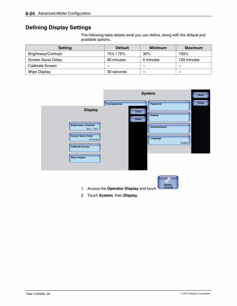
Advanced Melter Configuration6-24
Part 1120350_04 � 2014 Nordson Corporation
Defining Display Settings
The following table details what you can define, along with the default andavailable options.
Setting Default Minimum Maximum
Brightness/Contrast 75% | 75% 30% 100%
Screen Saver Delay 90 minutes 5 minutes 120 minutes
Calibrate Screen -- -- --
Wipe Display 30 seconds -- --
SystemDone
Formats/Units
Date/Time
Service Interval
Scheduler
Password
Display
Administration
Language
03/20/2012 4:40 PM
English
500 hours
Home
Date/Time
Service Interval
Scheduler
03/20/2012 4:40 PM
500 hours
DoneDisplay
Brightness / Contrast
Screen Saver Delay
Calibrate Screen
Wipe Display
Home
75% | 75%
5 minutes
1. Access the Operator Display and touch Master
Controls
2. Touch System, then Display.

Advanced Melter Configuration 6-25
Part 1120350_04� 2014 Nordson Corporation
3. Do the following to continue.
Touch Description
Brightness/Contrast Enhance the visibility and readability of thetouchscreen displays.
Screen Saver Delay The amount of time (default 5 minutes) of no userinteraction with the touchscreen before the screensaver appears.
The screen saver only displays the melter statusand its corresponding color. To extend the lifespanof the touchscreen itself, the brightness andcontrast are reduced from its current settings to30%
Touch anywhere on the screen to access theOperator Display.
Calibrate Screen Allows you to improve the accuracy of yourinteraction with the touchscreen.
Touch the + symbol to calibrate the touchscreen.
Wipe Display Locks the screen for 30 seconds, allowing you toclear dust from the touchscreen without touching abutton and accidentally changing a setting.
4. Touch Done.

Advanced Melter Configuration6-26
Part 1120350_04 � 2014 Nordson Corporation
Configuring Password ProtectionBy default, password protection is disabled.
NOTE: Refer to Table 6‐5 for an explanation of each security level.
The following are default password level numeric codes:
Level # Default Code Notes
1 1000 � Cannot start with the number 0 (zero).
� Can be one up to five numbers long.
� The largest 5 digit number is 65535.
� Each level must have a unique numeric code.
2 2000
3 3000
SystemDone
Formats/Units
Date/Time
Service Interval
Scheduler
Password
Display
Administration
Language
03/20/2012 4:40 PM
English
500 hours
Home
Date/Time
Service Interval
Scheduler
03/20/2012 4:40 PM
500 hours
Done
Help
Password
Create/Modify
Timeout
Set Security Level
5 minutes
Home
1. Access the Operator Display and touch Master
Controls
2. Touch System, then Password.
3. Do the following to continue. When finished, touch Done.
Touch Description
Create/Modify Modify the default numeric password code for eachlevel.
Timeout The amount of time (the default is 10 minutes) theselected password protection becomes active afterno user interaction with the touchscreen.
Set Security Level Refer to Table 6‐5 for an explanation of eachsecurity level.
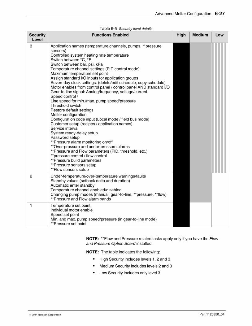
Advanced Melter Configuration 6-27
Part 1120350_04� 2014 Nordson Corporation
Table 6‐5 Security level details
SecurityLevel
Functions Enabled High Medium Low
3 Application names (temperature channels, pumps, **pressuresensors)Controlled system heating rate temperatureSwitch between °C, °FSwitch between bar, psi, kPaTemperature channel settings (PID control mode)Maximum temperature set pointAssign standard I/O inputs for application groupsSeven-day clock settings: (delete/edit schedule, copy schedule)Motor enables from control panel / control panel AND standard I/OGear-to-line signal: Analog/frequency, voltage/currentSpeed control / Line speed for min./max. pump speed/pressureThreshold switchRestore default settingsMelter configurationConfiguration code input (Local mode / field bus mode)Customer setup (recipes / application names)Service intervalSystem ready-delay setupPassword setup**Pressure alarm monitoring on/off**Over-pressure and under-pressure alarms**Pressure and Flow parameters (PID, threshold, etc.)**pressure control / flow control**Pressure build parameters**Pressure sensors setup**Flow sensors setup
ËËËËËËËËËËËËËËËËËËËËËËËËËËËËËËËËËËËËËËËËËËËËËËËËËËËËËËËËËËËËËËËËËËËËËËËËËËËËËËËËËËËËËËËË2 Under-temperature/over-temperature warnings/faults
Standby values (setback delta and duration)Automatic enter standbyTemperature channel enabled/disabledChanging pump modes (manual, gear-to-line, **pressure, **flow)**Pressure and Flow alarm bands
1 Temperature set pointIndividual motor enableSpeed set pointMin. and max. pump speed/pressure (in gear-to-line mode)**Pressure set point
NOTE: **Flow and Pressure related tasks apply only if you have the Flowand Pressure Option Board installed.
NOTE: The table indicates the following:
� High Security includes levels 1, 2 and 3
� Medium Security includes levels 2 and 3
� Low Security includes only level 3

Advanced Melter Configuration6-28
Part 1120350_04 � 2014 Nordson Corporation
Configuring Scheduled EventsUse the scheduler to time daily heater and standby events. Figure x-xillustrates a typical daily schedule.
Heaters On
Enter Standby - break
Heaters Off
Exit Standby
Enter Standby - shift change
Exit Standby
NOTE: About scheduling events:
� Define up to 12 events per day.
� Each day can have its own unique schedule.
� Copy and paste schedules to other days of the week.
� Scheduled events cannot cross over to the next day.
Creating a Schedule of events is a 3-step process
Step 1: Access the Scheduler and verify that the system date, time and day of week are correct.
Step 2: Define the first work day of the week that you want to start scheduling events.
Step 3: Switch On the Scheduler control.

Advanced Melter Configuration 6-29
Part 1120350_04� 2014 Nordson Corporation
Step 1: Access the Scheduler and verify that the system date, time andday of week are correct
SystemDone
Formats/Units
Date/Time
Service Interval
Scheduler
Password
Display
Administration
Language
03/20/2012 4:40 PM
English
500 hours
Home
Display
Administration
Language
English
Scheduler: Data/Time/Day Settings
Select day to edit:
Sun Mon ThuTue FriWed Sat
Sun Mon ThuTue FriWed Sat
Current System Date: 03/20/2012
Current System Time: 16:40
Current System Day: Tuesday
Cancel
Change Date
Home
1. Access the Operator Display and touch Master
Controls
2. Touch System, then Scheduler.
3. From the bottom section, make sure the Current System Date, Time andDay are correct.
� If the Date and Time are incorrect, touch Change Date and enter the
correct information.
� If the Day is incorrect, touch the appropriate day of the week button.
4. From the top section, touch the day of the week button that you want toschedule events. It is recommended that you start with the first workingday of the week, for example Monday, and work forward. You can onlycopy/paste schedules from one day to the next, not backwards.
5. Proceed to the step 2.

Advanced Melter Configuration6-30
Part 1120350_04 � 2014 Nordson Corporation
Step 2: Define the first work day of the week that you want to startscheduling event
Scheduler: Monday
Cancel
Cancel
Next Day
Add Heat Event Add Standby Event
Heat
Standby
6:30
10:00
18:00
10:25
Standby 15:00 15:25
Add Heat Event
Turn Heaters On:
Done
Cancel
Turn Heaters Off:
6:30
18:00
Home
1. Do the following to continue:
Touch Description
Add Heat Event
Enter the time when you want the heaters to switch On and Off.
Typically, you would have only one heat event per day.
Add Standby Event
Enter the time when you want the system to enter, then exit StandbyMode.
You can include multiple Standby events to include lunch breaks, shiftchanges and so on.
To remove the event.

Advanced Melter Configuration 6-31
Part 1120350_04� 2014 Nordson Corporation
2. Do you want to copy this exact schedule to the other days of the week?
If…. Then
Yes
a. Touch to copy the schedule into memory.
b. Touch Next Day.
c. Touch to paste the schedule to the day you want.
d. Repeat steps b and c until you are done. Proceed to Step 3.
No a. Touch Next Day to configure a different schedule.
b. Touch Done. Proceed to Step 3

Advanced Melter Configuration6-32
Part 1120350_04 � 2014 Nordson Corporation
Step 3: Switch On the Master Scheduler Control
Hopper
Set Point: 175�C
175�C
Reservoir
Set Point: 175�C
175�C
Zone 1A
Set Point: 175�C
175�C
Zone 1B
Set Point: 175�C
175�C
Zone 2A
Set Point: 175�C
175�C
Zone 2B
Set Point: 175�C
175�C
Zone 3A
Set Point: 175�C
175�C
Zone 3B
Set Point: 175�C
175�C
Zone 4A
Set Point: 175�C
175�C
Zone 4B
Set Point: 175�C
175�C
Zone 5A
Set Point: 175�C
175�C
Zone 5B
Set Point: 175�C
175�C
Zone 6A
Set Point: 175�C
175�C
Zone 6B
Set Point: 175�C
175�C
Zone 7A
Set Point: 175�C
175�C
Zone 7B
Set Point: 175�C
175�C
Pump 1Manual
45 RPMSet Point: 45 RPM
Pump 1Manual
45 RPMSet Point: 45 RPM
Pump 1GLT
45 RPMSet Point: 65 RPM
Pump 1Manual
45 RPMSet Point: 45 RPM
Melter Status:
Ready\OK
Recipes
SMALL SIZE
Done
Scheduler
Pump ControlHeater Control
Standby
Settings System
Master Controls
Scheduler: Off
Pumps: OnHeaters: On
Standby: Off
MasterControls
Heaters: On
Pump: On
Password: Disabled
1. Access the Operator Display and touch Master
Controls
2. Touch the Scheduler button to switch it On.
3. Touch Done.

Advanced Melter Configuration 6-33
Part 1120350_04� 2014 Nordson Corporation
Administrative Options and SettingsThe following sections detail the following:
� Managing recipes
� Viewing the event log
� Resetting to System Defaults
� Resetting password level codes
� Viewing firmware version information
� Viewing heaters On hours
� Locking out melter communication
� Changing RTD types
Accessing Administration Settings and Options
SystemDone
Formats/Units
Date/Time
Service Interval
Scheduler
Password
Display
Administration
Language
03/20/2012 4:40 PM
English
500 hours
Home
Date/Time
Service Interval
Scheduler
03/20/2012 4:40 PM
500 hours
Off
AdministrationDone
System Reset
Display/Save Diagnostics
Reset Password
Recipes
RTD Options
Lockout Communications
Hours Heaters On: 770
Firmware Version: 4.40
Motor Board 1 firmware version: 2.2
Motor Board 1 firmware version: -
Off
Home
1. Access the Operator Display and touch Master
Controls
2. Touch the System, then Administration.
Refer to the following sections for more information.
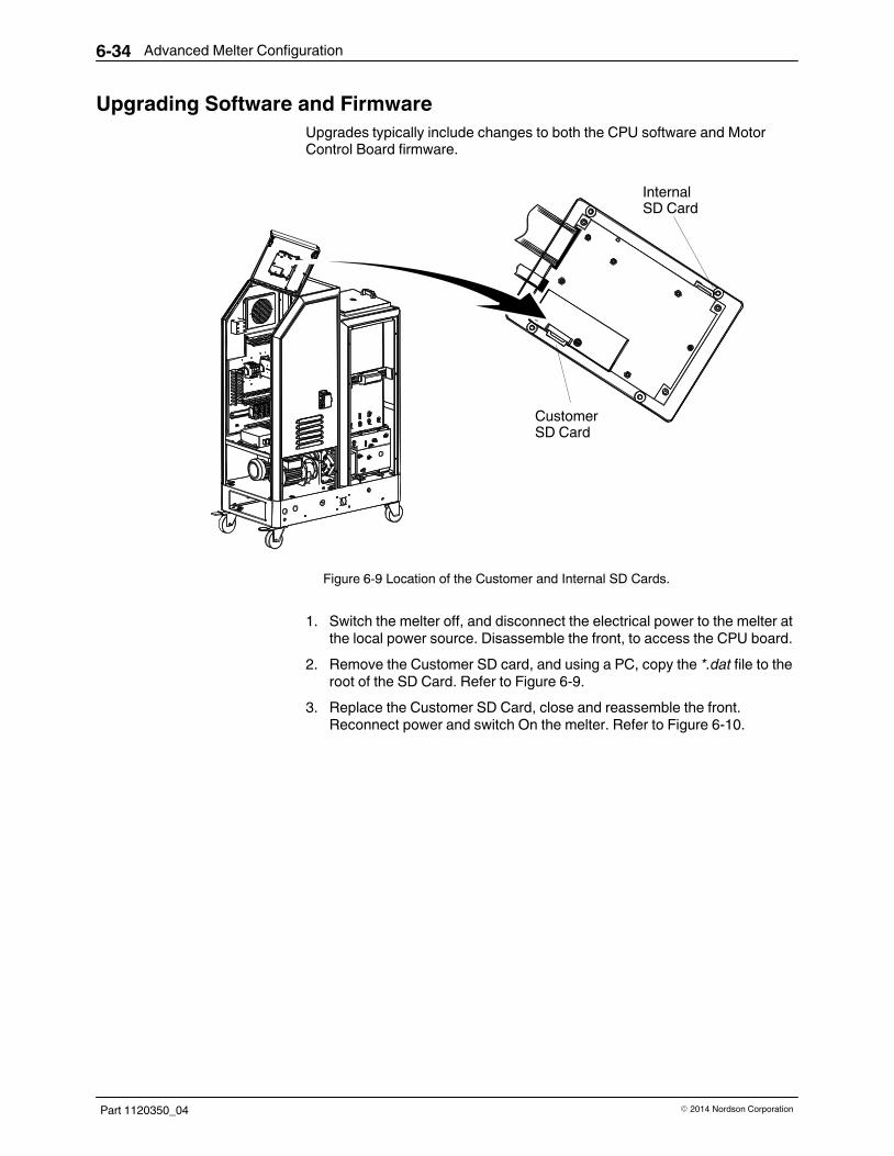
Advanced Melter Configuration6-34
Part 1120350_04 � 2014 Nordson Corporation
Upgrading Software and Firmware
Upgrades typically include changes to both the CPU software and MotorControl Board firmware.
Customer SD Card
Internal SD Card
Figure 6-9 Location of the Customer and Internal SD Cards.
1. Switch the melter off, and disconnect the electrical power to the melter atthe local power source. Disassemble the front, to access the CPU board.
2. Remove the Customer SD card, and using a PC, copy the *.dat file to theroot of the SD Card. Refer to Figure 6‐9.
3. Replace the Customer SD Card, close and reassemble the front.Reconnect power and switch On the melter. Refer to Figure 6‐10.
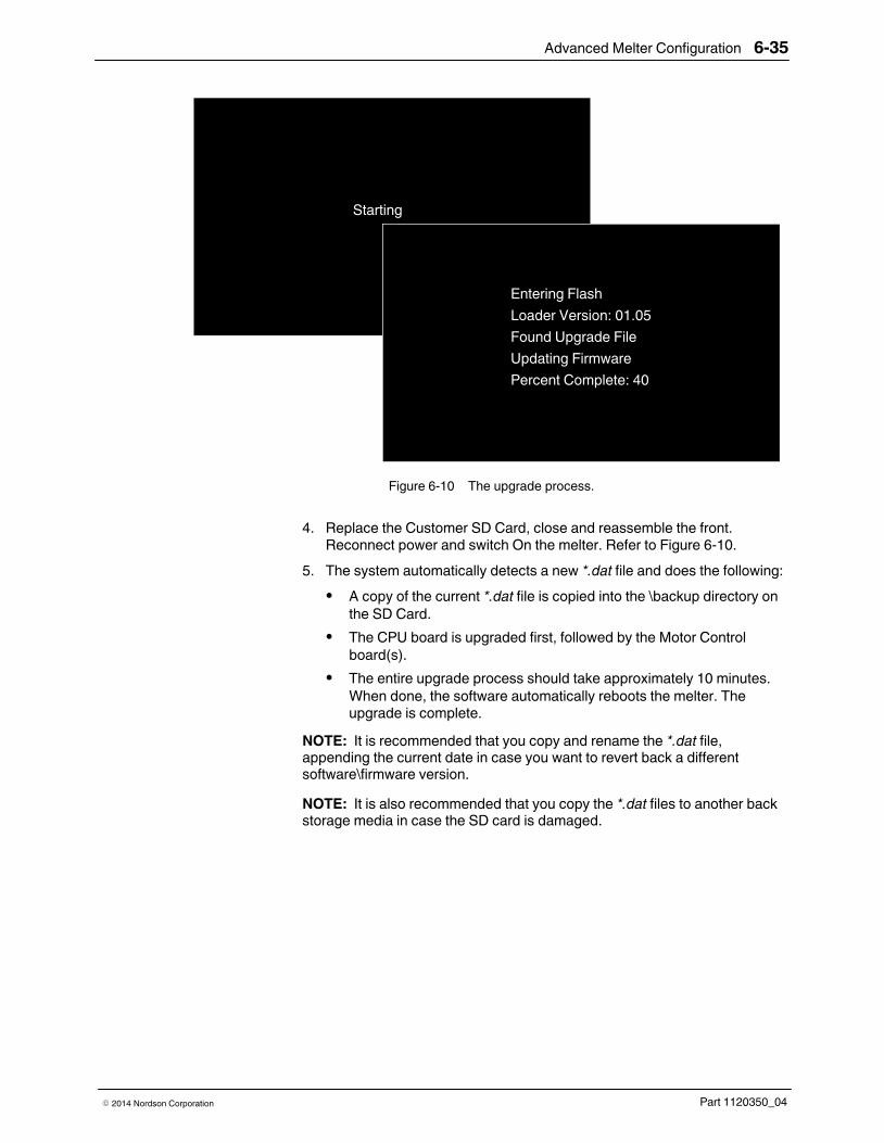
Advanced Melter Configuration 6-35
Part 1120350_04� 2014 Nordson Corporation
Starting
Entering Flash
Loader Version: 01.05
Found Upgrade File
Updating Firmware
Percent Complete: 40
Figure 6‐10 The upgrade process.
4. Replace the Customer SD Card, close and reassemble the front.Reconnect power and switch On the melter. Refer to Figure 6‐10.
5. The system automatically detects a new *.dat file and does the following:
� A copy of the current *.dat file is copied into the \backup directory on
the SD Card.
� The CPU board is upgraded first, followed by the Motor Control
board(s).
� The entire upgrade process should take approximately 10 minutes.
When done, the software automatically reboots the melter. Theupgrade is complete.
NOTE: It is recommended that you copy and rename the *.dat file,appending the current date in case you want to revert back a differentsoftware\firmware version.
NOTE: It is also recommended that you copy the *.dat files to another backstorage media in case the SD card is damaged.

Advanced Melter Configuration6-36
Part 1120350_04 � 2014 Nordson Corporation
Reverting back to a Previous Version
As part of the upgrade process, the current *.dat file is automatically copiedinto the \backup directory of the Customer SD Card.
1. Follow the same upgrading steps 1 and 2.
2. Using your PC, do the following:
� Navigate to the \backup directory and copy the *.dat file you want.
� Navigate to the root of the SD Card and paste the *.dat file.
� If you previously renamed the *.dat file, then you must change it back
to its original name.
3. Follow the same upgrading steps 4 and 5.

Advanced Melter Configuration 6-37
Part 1120350_04� 2014 Nordson Corporation
Managing Recipes
Use recipes to save production settings, such as zones and pump settings,as well as other melter settings including scheduled events, and securitysettings, to a file that you can use, modify and delete.
NOTE:
� You can share recipes with other AltaBlue™ Touch Adhesive Melters.
� Recipes are stored on the Customer SD Card. Refer to Figure 6‐9.
� Refer to table 6‐1 for more information about what is saved to a
recipe.
� The melter retains the settings of the previously loaded recipe, even if
you delete or decide not to make use of a recipe.
Accessing the Recipes Screen
You can access the Recipes screen by doing one of the following:
� From the Operator Display, touch Recipes.
‐ Refer to Figure 6‐11.
� From the Master Controls | System | Administration, touch Recipes.
‐ Refer to Figure 6‐12.
Displays the name of the currently loaded recipe, otherwise displays:
Recipes
Recipes
Nothing Loaded
Touch here to access the Recipes screen
Nothing Loaded
Figure 6‐11 Accessing Recipes from the Operator Display

Advanced Melter Configuration6-38
Part 1120350_04 � 2014 Nordson Corporation
AdministrationDone
System Reset
Display/Save Diagnostics
Reset Password
Recipes
RTD Options
Lockout Communications
Hours Heaters On: 770
Firmware Version: 4.40
Motor Board 1 firmware version: 2.2
Motor Board 1 firmware version: -
Off
Home
RecipesNext
Cancel
Load or Deletea Recipe
Do not use a Recipe
Save Recipe
Home
Figure 6‐12 Accessing Recipes from the Master Controls | Administration screen
1. Access the Recipes screen.
2. Decide what you want to do and touch Next to continue.
Task Touch Description
Load a recipe
Load or Delete aRecipe
Select an existing recipe you want use.
Touch Load to continue.
Delete a recipe Select an existing recipe you no longer want to use.
Touch Delete to continue.
NOTE: The melter retains the settings of the previouslyloaded recipe.
Unload and/or notmake use of anyrecipe
Do not use aRecipe
Unloads the currently loaded recipe.
Select this option when troubleshooting or performingmaintenance on the melter.
NOTE: The melter retains the settings of the previouslyloaded recipe.
Create a newrecipe
Save Recipe
Do the following:
1. Configure and test melter settings until it meets yourmanufacturing requirements.
2. Access the Recipes screen, touch Save Recipe andenter an easily identifiable recipe name.
NOTES:
� To update the settings of the recipe, enter the exact
same recipe name.
� The system unloads the currently loaded recipe, then
saves the new settings and automatically loads it.
Modify an existingrecipe

Advanced Melter Configuration 6-39
Part 1120350_04� 2014 Nordson Corporation
What's Being Saved in a Recipe
The following highlights what a recipe is saving to a file.
Table 6‐1 Recipe Details
General Information Administration Information
� Software Version
� Language
� Date, Time, Temp and Pressure format
� Under and Over Temperature threshold values
� Configuration settings for standard and expanded
Inputs and Outputs
� Service Alerts (enabled or disabled)
� Service Interval value
� RTD Type value
� Scheduler (enabled or disabled)
Settings and events for each day of the week
� Selected password level
� Numeric password code for each password
level
� Password Timeout value
Temperature Information Zone Information
� Standby Temperature
� Standby (enabled or disabled)
� Auto Exit Standby (enabled or disabled)
� Auto Exit Standby Time value
� Auto Heaters Off Time value
� Auto Standby Time value
� Zone (enabled or disabled)
� Default and user-defined names
� Set Point values
� PID values
Pump Information Flow and Pressure Information
� Pump (enabled or disabled)
� Default and user-defined names
� Auto Pump On (enabled or disabled)
� Number of installed Motor Control Boards
� Remote Pump (enabled or disabled)
� Specific pump operation mode settings
NOTE: Requires additional hardware.
� Pressure and flow channel default and user
defined names
� Specific Pressure and/or Flow configuration
settings
� PID values
� Flow/Pressure Alarm (enabled or disabled)
� Alarm settings
� Pressure Build (enabled or disabled)

Advanced Melter Configuration6-40
Part 1120350_04 � 2014 Nordson Corporation
Viewing the Event Log - Save Diagnostics
Use the event log to view a list of up to 200 of the most recent fault, alert, andparameter change events. You can save those events from memory to theInternal SD card. Refer to Figure 6‐9. The default file name is EventLog.xml.
Additionally, a Diagnosticsfile.xml, file is also written to the SD card. This filecontains, detailed melter information. The information contained in both filescan help Nordson technical support troubleshoot your issue.
NOTES:
� The system writes the entire event log to the SD card, regardless of
what level of detail you selected.
� The event log can display up to 200 events, after which the oldest
event is overwritten with new events.
� You cannot clear nor change the name of either file.
Recipes
RTD Options
Lockout Communications
Hours Heaters On
10.0797 770 hours
Display/Save DiagnosticsNext
DoneComplete EventLog
Faults Only
Alerts Only
Parameter/Set PointChanges
Display/Save Diagnostics Back
05/04/12 11:52:20 Event Ready enterDone
Save File
Source: System Status: OK
Zone/Parameter: 0 Zone/Sub-code: 0
05/04/12 11:50:50 Event Ready enter
Source: System Status: OK
Zone/Parameter: 0 Zone/Sub-code: 0
05/04/12 11:40:03 Event Zone control off
Source: HMI Status: OK
Zone/Parameter: 17 Zone/Sub-code: 0
05/04/12 11:34:29 Event Ready enter
Source: System Status: OK
Zone/Parameter: 0 Zone/Sub-code: 0
Old value: 1 New value: 0
Home
1. Access the Operator Display and touch Master
Controls
2. Touch Settings button, then Administration.
3. Touch Display/Save Diagnostics and select which level of detail youwant to view.
4. Touch Next to continue.

Advanced Melter Configuration 6-41
Part 1120350_04� 2014 Nordson Corporation
5. Decide what you want to do next.
Touch Description
Back Select a different event log option to view.
Done Exit the event log.
Save File Save both the event log and the diagnostic file tothe Internal SD card. Refer to Figure 6‐9.
Touch this button only one-time. Depending on thenumber of events in the log, this can take a fewminutes.
When done, the Attention message appears,indicating The diagnostics file was saved to the SDCard.
The default names are:
EventLog.xml
Diagnosticsfile.xml
6. Touch Done.

Advanced Melter Configuration6-42
Part 1120350_04 � 2014 Nordson Corporation
Resetting to System Defaults
Use system reset to revert all user definable software settings back to factorydefaults.
NOTES:
� Recipes and event log information are stored on the customer
supplied SD card, and are therefore NOT deleted or changed.
� Use a recipe to restore melter settings.
AdministrationDone
System Reset
Display/Save Diagnostics
Reset Password
Recipes
RTD Options
Lockout Communications
Hours Heaters On: 770
Firmware Version: 4.40
Motor Board 1 firmware version: 2.2
Motor Board 1 firmware version: -
Off
Home
Are you sure you want to revert back to factory settings?
Yes No
Are you sure you want to revert back to factory settings?
Yes No
Confirm
1. Access the Operator Display and touch Master
Controls
2. Touch System, then Administration.
3. Touch System Reset. A pop-up message appears.
4. Touch Yes to revert all user definable settings back to factory defaults.
5. Touch Done.

Advanced Melter Configuration 6-43
Part 1120350_04� 2014 Nordson Corporation
Resetting Password Codes
Use Reset Password to revert all 3 levels of password codes back to theirdefault codes.
The following are the default password level numeric codes:
Level # Default Code Notes
1 1000 � Cannot start with the number 0 (zero).
� Can be one up to five numbers long.
� The largest 5 digit number is 65535.
� Each level must have a unique numeric code.
2 2000
3 3000
AdministrationDone
System Reset
Display/Save Diagnostics
Reset Password
Recipes
RTD Options
Lockout Communications
Hours Heaters On: 770
Firmware Version: 4.40
Motor Board 1 firmware version: 2.2
Motor Board 1 firmware version: -
Off
Home
Confirm
Are you sure you want to reset all passwords tofactory default?
Yes No
1. Access the Operator Display and touch Master
Controls
2. Touch System, then Administration.
3. Touch Reset Password. A pop-up message appears.
4. Touch Yes to revert all three password level codes to their default values.
5. Touch Done.

Advanced Melter Configuration6-44
Part 1120350_04 � 2014 Nordson Corporation
Viewing Software Version and Heater On Hours
Access the Administration screen to view:
� Firmware Version
� Hours Heaters On
AdministrationDone
System Reset
Display/Save Diagnostics
Reset Password
Recipes
RTD Options
Lockout Communications
Hours Heaters On: 770
Firmware Version: 4.40
Motor Board 1 firmware version: 2.2
Motor Board 1 firmware version: -
Off
Home
1. Access the Operator Display and touch Master
Controls
2. Touch System, then Administration.
3. Look at the Firmware Version and/or Hours Heaters On button formore information.
4. Touch Done.

Advanced Melter Configuration 6-45
Part 1120350_04� 2014 Nordson Corporation
Locking Out Communications
Use Lockout Communication to prevent remote access to the melter whileyou are troubleshooting or performing maintenance on the melter.
AdministrationDone
System Reset
Display/Save Diagnostics
Reset Password
Recipes
RTD Options
Lockout Communications
Hours Heaters On: 770
Firmware Version: 4.40
Motor Board 1 firmware version: 2.2
Motor Board 1 firmware version: -
Off
Home
1. Access the Operator Display and touch Master
Controls
2. Touch System, then Administration.
3. Touch the Lockout Communication button to toggle it On or Off
4. Touch Done.

Advanced Melter Configuration6-46
Part 1120350_04 � 2014 Nordson Corporation
Changing RTD Types
You must let the software know when you change RTD types, otherwise thesoftware may display erroneous data and system messages.
Default Available Options
NI120 � NI120
� PT100
AdministrationDone
System Reset
Display/Save Diagnostics
Reset Password
Recipes
RTD Options
Lockout Communications
Hours Heaters On: 770
Firmware Version: 4.40
Motor Board 1 firmware version: 2.2
Motor Board 1 firmware version: -
Off
Home
RTD OptionsDone
NI120
PT100
Home
1. Access the Operator Display and touch Master
Controls
2. Touch System button, then Administration.
3. Touch RTD Options and select the appropriate installed RTD type.
4. Touch Done.
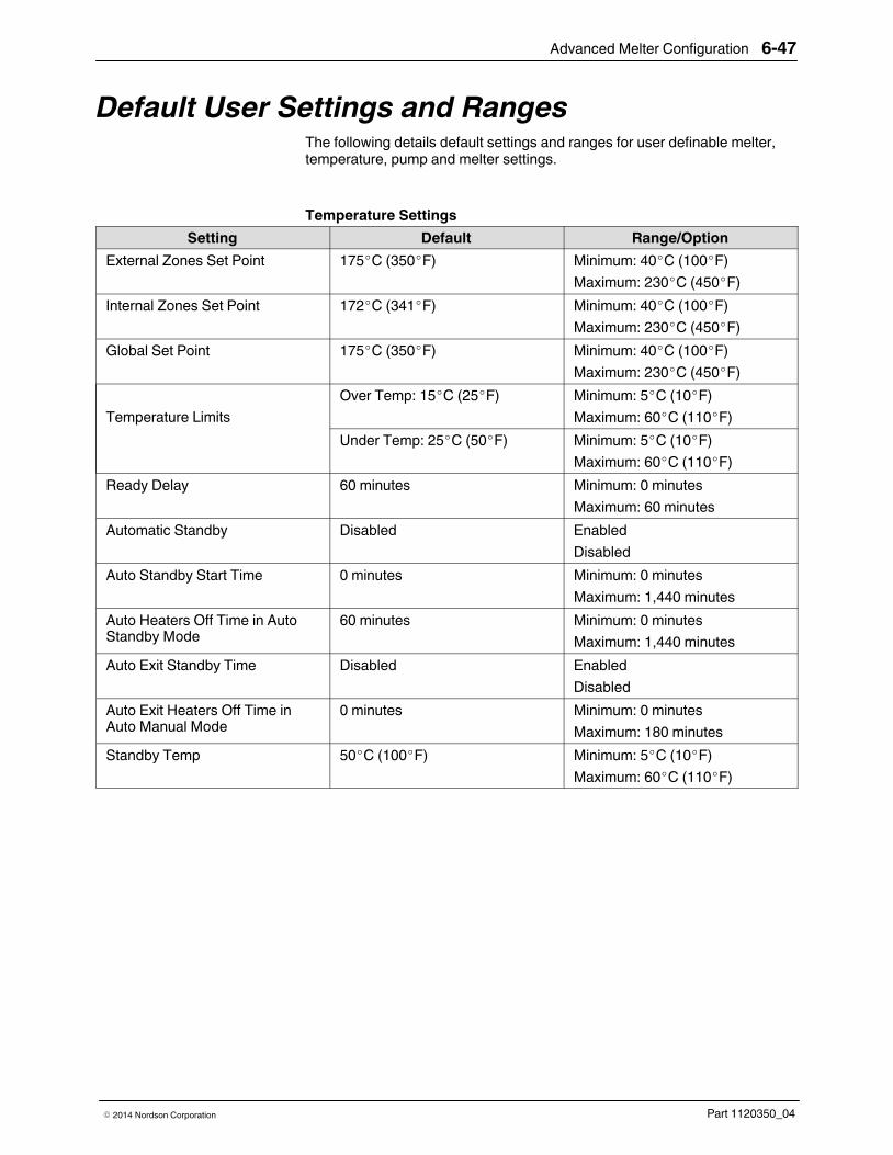
Advanced Melter Configuration 6-47
Part 1120350_04� 2014 Nordson Corporation
Default User Settings and RangesThe following details default settings and ranges for user definable melter,temperature, pump and melter settings.
Temperature Settings
Setting Default Range/Option
External Zones Set Point 175�C (350�F) Minimum: 40�C (100�F)
Maximum: 230�C (450�F)
Internal Zones Set Point 172�C (341�F) Minimum: 40�C (100�F)
Maximum: 230�C (450�F)
Global Set Point 175�C (350�F) Minimum: 40�C (100�F)
Maximum: 230�C (450�F)
Temperature Limits
Over Temp: 15�C (25�F) Minimum: 5�C (10�F)
Maximum: 60�C (110�F)
Under Temp: 25�C (50�F) Minimum: 5�C (10�F)
Maximum: 60�C (110�F)
Ready Delay 60 minutes Minimum: 0 minutes
Maximum: 60 minutes
Automatic Standby Disabled Enabled
Disabled
Auto Standby Start Time 0 minutes Minimum: 0 minutes
Maximum: 1,440 minutes
Auto Heaters Off Time in AutoStandby Mode
60 minutes Minimum: 0 minutes
Maximum: 1,440 minutes
Auto Exit Standby Time Disabled Enabled
Disabled
Auto Exit Heaters Off Time inAuto Manual Mode
0 minutes Minimum: 0 minutes
Maximum: 180 minutes
Standby Temp 50�C (100�F) Minimum: 5�C (10�F)
Maximum: 60�C (110�F)

Advanced Melter Configuration6-48
Part 1120350_04 � 2014 Nordson Corporation
Pump Settings
Setting Default Range/Option
Operation Mode Manual Manual
Gear-to-Line
* Pressure Control
* Flow Control
NOTE: *Requires additionalhardware
Pump RPM 0 Minimum: 0 RPM
Maximum: 94 RPM
Auto Pump Off Pumps 1-4
Remote Control None set Off
On

Advanced Melter Configuration 6-49
Part 1120350_04� 2014 Nordson Corporation
Melter Settings
Setting Default Range/Option
Service Interval 500 hours Minimum: 0 hours
Maximum: 8760 hours
Scheduler No events defined Minimum: 2 events per day
Maximum: 12 events per day
Password Protection No Password Protection High
Medium
Low
No Password Protection
Password Level Codes Level 1: 1000
Level 2: 2000
Level 3: 3000
Minimum: 1
Maximum: 65535
NOTE: Code levels must beunique.
Password Timeout 1 minute Minimum: 1
Maximum: 60
Display Brightness/Contrast 75% | 75% Minimum: 30%
Maximum: 100%
Display Screen Saver Delay 1 minute Minimum: 1 minute
Maximum: 120 minutes
RTD Options NI120 NI120
PT100
Lockout Communications Off Off
On
Inputs/Outputs
Inputs Inputs:
#1: Automatic Standby
#2: Standby
#3: Heater Control
#4: External Zone # A/B
Disabled
Standby
Heater Control
Pump (Control)
External Zone # A/B
Automatic Standby (Availableonly for Input #1
Outputs Outputs:
#1: Ready
#2: Fault
#3: Tank Low
Disabled
Ready
Ready-Pump On
Fault
Tank Low
Alert
Service Reminder

Advanced Melter Configuration6-50
Part 1120350_04 � 2014 Nordson Corporation

Service 7-1
Part 1120350_04� 2014 Nordson Corporation
Section 7
Service
WARNING! Allow only qualified personnel to perform the following tasks.Follow the safety instructions in this document and all other relateddocumentation.
Maintenance is an important preventive measure for maintaining operatingsafety and extending the lifetime of the unit. It should not be neglected underany circumstances.
Relieving System Pressure
WARNING! System and material pressurized. Relieve system of pressurebefore disconnecting hoses, applicators and hot melt handapplicators.Failure to observe can result in serious burns.
Through the Applicators 1. Disable the motor(s).
2. Place a container under the nozzle(s) of the applicator/assemblyhandapplicator.
3. Activate the solenoid valve(s) electrically or manually; or, pull the triggerof the assembly handapplicator. Repeat this procedure until no morematerial flows out.
4. Re‐use the material or properly dispose of it according to localregulations.

Service7-2
Part 1120350_04 � 2014 Nordson Corporation
Through the Melter Drain Valves 1. Disable the motor(s).
2. Place a container under the drain valve ports located on the bottom of themanifold.
3. Open all the drain valves. Adhesive will drain from the valves.
4. When adhesive stops draining, close the drain valves.
5. Re‐use the material or properly dispose of it according to localregulations.
Figure 7-1 Location of the melter drain valves

Service 7-3
Part 1120350_04� 2014 Nordson Corporation
Preventive Maintenance Schedule The maintenance intervals are general guidelines based on experience.Depending on the operating environment, production conditions and melterhours of operation, other scheduled maintenance tasks may provenecessary.
Melter part Activity Interval Refer To
Complete melter External cleaning Daily External Cleaning
Inspect for externaldamage
Daily
Purge with cleaning agent When material is changed Changing theMaterial Type
Fan and air filter Check filter, clean orreplace if necessary
Clean fan screen
Depending on dust accumulation;daily if necessary
Fan and Air Filter
Power cable Inspect for damage Every time the melter is serviced
Air hoses Inspect for damage Every time the melter is serviced
Pump Tighten the gland bolt (ifpresent)
After initial startup Pump
Check for leakage, tightengland bolt (if present) ifnecessary
Dependent on hours of operation,pump speed and pump temperature
Recommendation: Monthly
Tighten fixing screws Every 500 hours of operation
Motor / gear box / coupling Clean fan cover Depending on dust accumulation;daily if necessary
Motor and GearBox
Change lubricant Every 15�000 hours of operation orevery 2 to 3 years
Pressure control valve Disassemble and clean Every six months Pressure ControlValve
Filter cartridge Replace filter cartridge
Disassemble and cleanfilter cartridge
Depending on degree of materialpollution
Recommendation: Every 1000hours of operation
Filter Cartridge
Tank Clean tank by hand When there is material residue intank
Cleaning the Tank
Tighten fixing screws Every 500 hours of operation

Location of the optional motionswitch
Service7-4
Part 1120350_04 � 2014 Nordson Corporation
Locking Out the Motor Drives To perform some troubleshooting and repair activities, the main power to themelter needs to be on and/or the melter needs to be at applicationtemperature. To prevent injury, the optional motion switch can be used tolock out the motor drives while leaving the main power on.
To lock out the motor drives but leave the main power on, place the motionswitch in the OFF position. The main power to the melter will remain on andthe melter will stay at application temperature.
External Cleaning
CAUTION! Do not damage or remove safety labels. Damaged or removedsafety labels must be replaced by new ones.
� Remove material residue only with a cleaning agent recommended by
the material supplier. Heat with an air heater if necessary.
� Remove dust, flakes, etc. with a vacuum cleaner or a soft cloth.
� Nordson recommends the orange cleaning agent, P/N 771192 (12 spray
bottles, 0.5 l each).

Service 7-5
Part 1120350_04� 2014 Nordson Corporation
Changing the Material Type 1. Run the melter until empty.
2. Determine whether the new material may be mixed with the old material.
� May be mixed: Remaining old material can be flushed out using the
new material.
� May not be mixed: Thoroughly purge the unit with a cleaning agent
recommended by the material supplier.
NOTE: Properly dispose of the old material according to local regulations.
Detaching the Exterior Panels Open the protective panels with a 4 mm Allen key.
On the inside
Fan and Air Filter The air filters must be cleaned (knocked out) or replaced, depending on dustaccumulation.
Refer to Section 9, Parts, for the filter part number.

Service7-6
Part 1120350_04 � 2014 Nordson Corporation
Motor and Gear Box
Changing the Motor Lubricant
Remove the gear motor assembly from the melter.
� Use only the stated lubricant or one that has proven to be equivalent
(refer to Lubricant Selection). Using any other lubricant can result inpremature wear and/or damage to the gear box.
� Drain lubricant when warm.
� Properly dispose of the old lubricant according to local regulations.
CAUTION! Never mix different types of lubricants.
Lubricant Changing Interval
Operating temperature < 100 �C / 212 �F:
Every 15�000 hours of operation or at least every 4 years.
Lubricant Capacity
Ensure that the upper gears and rolling bearings are properly lubricated.
Lubricant Selection
Lubricant manufacturer Mineral oil CLP 220
AGIP Blasia 220
ARAL Degol BMB 220 or Degol BG 220
BP Energol GR-XP 220
DEA Falcon CLP 220
ESSO Spartan EP 220 or GP 90
KLÜBER Klüberoil GEM 1-220
OPTIMOL Optigear 220
SHELL Omala Oil 220
TEXACO Geartex EP-A SAE 85 W-90

Service 7-7
Part 1120350_04� 2014 Nordson Corporation
Replacing a Motor or Coupling
Follow this procedure to replace a motor or coupling. You will need thefollowing items:
� appropriate tools
� replacement motor or coupling
� anti‐seize lubricant (if needed)
1. Disconnect and lock out electrical power to the melter.
2. Remove the hydraulic side covers and the left and right control cabinetside covers. Refer to Detaching the Exterior Panels earlier in this sectionas needed.
3. Disconnect the motor cable wires, noting their terminal positions.
4. See Figure 7‐2. Loosen the screws that secure the motor to the base ofthe melter and then slide the motor back.
5. Slide the coupling sleeve (2) off of the coupling hubs (1 and 3), loosenthe hub set screws, and remove the hubs.
Adjustable
Figure 7-2 Coupling assembly components
1 Motor coupling hub
2 Coupling sleeve
3 Pump coupling hub

Service7-8
Part 1120350_04 � 2014 Nordson Corporation
Replacing a Motor or Coupling (contd)
6. Remove the protective coating from the new motor shaft, slide thereplacement (if applicable) motor coupling hub onto the motor shaft, andtighten the hub set screws.
7. Install the replacement (if applicable) pump coupling hub on the pumpshaft, ensure that it is flush with the pump shaft, adjust the motor shaft toalign and tighten the hub set screws.
8. Loosely install the replacement motor assembly and slide the assembly,including the motor coupling hub and sleeve, toward the pump until thecoupling sleeve engages with pump coupling hub.
9. Ensure that the coupling sleeve cannot move, then slide the motorassembly back 4 mm (0.16 in.), as indicated in Figure 7‐3.
Figure 7-3 Moving the motor assembly back 4 mm (0.16 in.)
10. Tighten the screws that secure the motor to the base of the melter
11. To ensure proper motor and pump shaft alignment, ensure that you canfreely slide the coupling sleeve back and forth by about 4 mm (0.16 in.)each way.
12. Reconnect the motor cable wires to the same terminals from which theywere disconnected.
13. Reinstall the melter covers and restore the system to normal operation.

Service 7-9
Part 1120350_04� 2014 Nordson Corporation
Pump
Tightening the Pump Screws 1. Ensure that the melter is turned off and that power has been
disconnected and locked out.
2. Ensure that the melter, tank, manifold, and pump are cold.
3. See Figure 7‐4. Tighten the screws to 25 N�m (222 in.‐lb).
Figure 7-4 Tightening the pump screws
4. Restore the system to normal operation.

Pump gland bolt
Service7-10
Part 1120350_04 � 2014 Nordson Corporation
Tightening the Pump Gland Bolt
NOTE: This procedure applies only to pumps with a gland bolt.
On pumps with a gland bolt, adhesive may leak from the self‐sealing pumpshaft packing at regular intervals. When leakage occurs, tighten the pumpgland bolt.
1. Heat the pump to application temperature using a heated air blower.
2. See Figure 7‐5. Using a 24‐mm short‐handle, open‐end wrench (with a15‐degree offset), tighten the pump gland bolt approximately 1/4 of a turnclockwise (in the direction of pump rotation). When the bolt can no longerbe tightened, replace the pump.
3. Restore the system to normal operation.
Figure 7-5 Tightening the pump gland bolt (clockwise)

Service 7-11
Part 1120350_04� 2014 Nordson Corporation
Replacing a Pump
Follow this procedure to replace a pump. You will need the following items:
� tool kit, including a torque wrench
� drain pan
� cleaning supplies
� replacement pump
� replacement pump O‐rings
� O‐ring lubricant
� anti‐seize lubricant
NOTE: To rebuild a pump, contact your Nordson representative forassistance.
1. Ensure the melter is at operating temperature.
2. Relieve system pressure. Refer to Section 1, Safety.
3. See Figure 7‐6. Close the tank isolation valve.
Figure 7-6 Location of the tank isolation valve

Service7-12
Part 1120350_04 � 2014 Nordson Corporation
Replacing a Pump (contd)
4. Remove the hydraulic side covers. Refer to Detaching the ExteriorPanels earlier in this section as needed.
5. Place a drain pan under the pump.
6. See Figure 7‐7. Loosen the screws that secure the motor to the base ofthe melter and then slide the motor back.
7. Slide the coupling sleeve (2) off of the coupling hubs (1 and 3), loosenthe pump coupling hub set screws, and remove the pump coupling hub.
Adjustable
Figure 7-7 Coupling assembly components
1 Motor coupling hub
2 Coupling sleeve
3 Pump coupling hub

Service 7-13
Part 1120350_04� 2014 Nordson Corporation
8. See Figure 7‐8. Remove the pump screws (3) and then remove the pump(2) and O‐rings (1).
440300046
1
2
3
1 2
3
Figure 7-8 Replacing a pump (single-stream and dual-stream pumps shown)
1 O‐rings 2 Pump 3 Pump screw
9. Clean the surface of the manifold where the pump mates to it.
10. Allow the melter to cool to room temperature.
11. Install the pump coupling hub on the pump shaft, ensure that it is flushwith the pump shaft, adjust the motor shaft to align and tighten the hubset screws.
12. Apply O‐ring lubricant to new pump O‐rings and install them on the pump.
13. Apply anti‐seize lubricant to the pump screws and secure the new pumpto the manifold with the screws. Use a torque wrench to tighten thescrews in a criss‐cross manner to 25�N�m�(222 in.‐lb).

Service7-14
Part 1120350_04 � 2014 Nordson Corporation
Replacing a Pump (contd)
14. Slide motor assembly, including the motor coupling hub and sleeve,toward the pump until the coupling sleeve engages with pump couplinghub.
15. Ensure that the coupling sleeve cannot move, then slide the motorassembly back 4 mm (0.16 in.), as indicated in Figure 7‐9.
Figure 7-9 Moving the motor assembly back 4 mm (0.16 in.)
16. Tighten the screws that secure the motor to the base of the melter
17. To ensure proper motor and pump shaft alignment, verify that you canfreely slide the coupling sleeve back and forth by about 4 mm (0.16 in.)each way.
18. Restore the system to normal operation.

Service 7-15
Part 1120350_04� 2014 Nordson Corporation
Filter Cartridge
To replace the filter cartridge
1. Ensure the melter is at operating temperature.
2. Relieve system pressure. Refer to Section 1, Safety.
M10
SW 24
3. Apply high temperature grease to all threads and O‐rings.
4. Insert the filter cartridge and tighten it to approximately 15 N�m(133�in.‐lb).
5. Feed material by allowing the pump to run until the material comes out ofthe hose connection or applicator free of bubbles.
6. Properly dispose of material according to local regulations.

Service7-16
Part 1120350_04 � 2014 Nordson Corporation
Filter Service Kit Each kit contains three O‐rings, filter sheath, filter screen andhigh‐temperature grease.
Service Kit, for P/N refer to Section 7, Parts.
Required tools:Open-jawed wrench, size 24 and size 13
3
2
2
2
Size 13
1
Size 24
1. Disassemble the hot filter cartridge (material must be fluid).
2. Replace filter sheath (1), O-rings (2) and filter screen (3).
3. Clean all other parts.
4. Apply grease to all threads and O-rings.

+−
Adjusting the set screw
Service 7-17
Part 1120350_04� 2014 Nordson Corporation
Pressure Control Valve
To replace the pressure control valve
X
Figure 7-10 Pressure control valve set screw insertion depth
NOTE: Screw in only when valve and pump are warm and material is soft.
1. Ensure the melter is at operating temperature.
2. Relieve system pressure. Refer to Section 1, Safety.
3. Measure and make a note of the insertion depth of the set screw(dimension X). This way the insertion depth can be replicated afterreassembly.
4. To prevent adhesive from leaking into the valve bore, drain the tank.Refer to Draining Material from the Tank later in this section as needed.
5. Remove the old pressure control valve.
6. Apply high temperature grease to all threads and O‐rings.
7. Slide the valve into the hole and tighten with torque wrench(15 N�m / 133 in.‐lb).
8. Adjust the setting screw to the recorded dimension X.
� Turning to the right increases material pressure.
� Turning to the left decreases material pressure.

Service7-18
Part 1120350_04 � 2014 Nordson Corporation
Pressure/Circulation Control Valve Service Kit Each kit contains two O‐rings and high‐temperature grease.
Service kit P/N: 394600
Required tools:Open-jawed wrench, size 24PliersTorque wrench
1. Heat melter to operating temperature.
WARNING: Hot! Risk of burns. Wear appropriate protectiveclothing/equipment.
2. Relieve melter pressure.
3. Measure insertion depth. Refer to Pressure Control Valve.
4. Use an open-jawed wrench to screw out the pressure control valve, then extract with apliers.
5. Remove old O-rings and disassemble and clean pressure control valve. Refer toSection 7, Parts, for a detailed drawing.
NOTE: Disassemble valve only when warm.
6. Install new O-rings. Apply grease to all threads and O-rings.
7. Guide pressure control valve into the hole when the melter is warm and tighten withtorque wrench.
Starting torque: 15 N�m (133 in.-lb)
8. Adjust set screw. Refer to Pressure Control Valve.

Service 7-19
Part 1120350_04� 2014 Nordson Corporation
Cleaning the Tank
Draining Material from the Tank
Pump material out of the melter.
CAUTION! Do not feed charred material though the applicator. Particles canblock the applicator. Instead unscrew hose.
Cleaning the Tank by Hand
Cold material can usually be peeled off of the sides of the tank. If necessary,first heat tank to material softening temperature, usually approximately70 °C / 158 °F.
NOTE: The inside of the tank is release coated. Do not use metallic tools toclean. Do not use wire brushes! This could damage the release coating.
Tightening the Fixing Screws
Heating and cooling that occurs during daily operation can cause the fixingscrews to loosen. Tighten screws as indicated in the table below.
NOTE: Tighten fixing screws only using a torque wrench and when themelter is cold.
Connection Thread Torque
Tank/reservoir M 6 6−8 N�m / 53−71 in.-lb
Manifold/reservoir (high melt) M 8 5−7 N�m / 44−62 in.-lb

Service7-20
Part 1120350_04 � 2014 Nordson Corporation
Main PCA Board
To replace the main PCA board
1. Disconnect power to the melter at the local disconnect switch.
2. Switch the melter off.
3. See Figure 7‐11. Open the electrical enclosure access panel and locatethe main PCA board.
Figure 7-11 Location of the main PCA board
4. Disconnect all of the power and control cables from the board.
5. Remove the four fastening screws that hold the board on the mountingstuds and then remove the board.
NOTE: Before installing the new board, you must ensure that the boardis properly configured for the type of temperature sensors present on themelter. If the melter uses 100‐ohm platinum sensors, the jumpersconnected to the JP1 terminal on the old board must be removed andthen installed on the new board. Figure 7‐12 shows the location ofterminal JP1 on the main PCA board. Figures 7‐13 and 7‐14 show thejumpers installed and not installed, as appropriate for each type of melter.

Service 7-21
Part 1120350_04� 2014 Nordson Corporation
R108
R7
R65
C55
R92
C6
C66
C32
C74
R127
R88
R72
R9
R61
R14
R11 DS5
R82
R49
D10R
79
R12
R102
R69
R90
DS16
R130
R87
RV
13
RN3
R103
R53
R47
Q5
Q12
R78
R59
+ C82
Q24
R129
R73
C80
C22
RV 5
RN
9
C79
R56
C69
R100
C84
R34
C8
C3
RV
7C
4
RV
12
C72
RV
11C
10 C23
C25
C26
R115
R112
Q7
Q9
C28
C29
R67
R66
R71
R117
L4
R58
R52
R36
R33
C53
RV 6C1
R80
R136
R133D8
R134 R135U5
C7 RN10
R106
R51
R57
Q14
R39R42
R83R37
R74
U12
R44R45C77
R38
R4R3
Q26
Q17
R99Q18
R121 R101
R8
R118
Q25
R6DS3
C47
DS4
L3
R96
C43
C44
R70
Q23
R93 R5
R55
Q8
R16
R10DS7
D12
C54
R84
R85
Q22
R17
R109
Q10
DS6
R76
R122
R131
D11
R132
Q13
1J2
R86
RV
10
R26
XP5
+C58
R111
R123 U26
C51
L2
U4
+C12
RN5
R89
XP6
C31RN6RN4
DS13
R104
R54
R48
DS8
DS12
R35
R60
R64
DS10
DS11
R116
R94
Q16
R40 R41C39
U23
D5
R2
R43R46
C2
R128R1
+
C40
R75
R119
R120
C37
C18
RN
1
C15
RN
11
C17
R95
Q20
Q19
C21 C20R15
RN
2
C19
R77
R113
1
X2
C70 C71
R62
1
X3
D3
R50
C46
C83
C68 C73
R97
R124
U21
C48 C49
RV
9
C61
XP
2
R110
R98
C36
C24
C9
C5
U3
U25
DS15
+C
35
DS14
DS9
C27
C30
C75
U2
+
C16
DS17
R13
C67
C62RV 1
R68
RV 3
C76
C11
R91D4
RN
7
C60
R81 R20
Q15
DS2
XT1
C42
C41
RV 8
C50
D17
R19
R107
U20
U10
U19
U15
U18
U9
1XP3
RV 2
X7
D1
D6
RV 4
1XP4
C65
D2
D7
D14
U1
U17
U14
JP2
C63
R22
R63
U16
C56
D16
R18
51
26JP1
1 33
J1
1
X1
C52
C64
C45
L1
R114
R105
U24
U13
3
12
1
X5
U7
T1
HSNK1
C78
+
C59
X6
XP
1
D18
+
C57
3
12
1
X4
K1
++
U22
F3
F4
F6 F5
F1F2
F11
F12
F7
F8 F10F95A
10A
6.3A
2A
2A
5A
10A
6.3A
6.3A
6.3A 6.3A6.3A
+
Q6 Q11
Figure 7-12 Location of the JP1 terminal on the main PCA board

Service7-22
Part 1120350_04 � 2014 Nordson Corporation
Main PCA Board (contd)
6. If 100‐ohm platinum sensors are present on the melter:
a. Go to System>Administration>RTD Options and select Pt100.
NOTE: For 120‐ohm nickel melters, temperature sensor jumpers arenot required in this location, as shown in Figure 7‐14.
b. Locate the JP1 terminal on the replacement board.
c. Install one of the jumpers removed from the old board betweenterminals 1 and 2.
d. Install the second jumper between terminals 5 and 6. Figure 7‐13shows the jumpers installed.
Figure 7-13 100-ohm platinum melter—jumpers installed
Figure 7-14 120-ohm nickel melter—no jumpers installed
7. Install the replacement board inside the melter electrical enclosure usingthe fastening screws removed previously.
8. Reconnect all of the power and control cables to the replacement boardand close the electrical access panel.
9. Restore power to the melter and switch the melter on. Verify that themelter starts normally.

Service 7-23
Part 1120350_04� 2014 Nordson Corporation
Maintenance Record Form Melter part Date / Name Date / Name Date / Name
Pump
Motor / gear box
Fixing screws on pump andtank
Air filter
Tank
Pressure control valve

Service7-24
Part 1120350_04 � 2014 Nordson Corporation
Filter cartridge

Troubleshooting 8-1
Part 1120350_04� 2014 Nordson Corporation
Section 8
Troubleshooting
WARNING! Allow only qualified personnel to perform the following tasks.Follow the safety instructions in this document and all other relateddocumentation.
WARNING! Troubleshooting activities may sometimes have to be carried outwhen the melter is energized. Observe all safety instructions and regulationsconcerning energized unit components (active parts). Failure to observe mayresult in an electric shock.
Safety� Never disconnect cables from, or reconnect cables to, the main board
while the melter is energized.
� Before breaking any hydraulic connection, always relieve system
pressure. Refer to Relieving System Pressure in Section 7, Service.
� Refer to the safety information provided with optional equipment.
� If the melter is removed from its sub‐base for diagnostic checks or
service, ensure that the ground lead between the chassis and thesub‐base is re‐attached when the melter is reconnected to the sub‐base.
NOTE: Refer to Administrative Options and Settings located in Chapter 6 ofthis manual.

Troubleshooting8-2
Part 1120350_04 � 2014 Nordson Corporation
Touch Screen Alerts and Faults The Nordson AltaBlue Touch Adhesive melter diagnoses many alert andfault conditions that may occur during operation. An “alert” condition is asituation in which a potential problem may be occurring with the melter,pump, applicator or hose. The melter will operate under an “alert” conditionunless the problem goes unresolved, at which point the melter will go into a“fault” condition, during which the melter will shut down until the problem isresolved.
Refer to the appropriate table for more information.
About Touch Screen Messages
Pump and Zone Alerts/Faults
Table 8-1 Pump and Zone Alerts/Faults
Screen Message Affect on Melter Cause Corrective Action(s)
Internal or External
Temperature for[ZoneName] hasdropped belowdefined setpointthreshold
Alert condition - anissue has beendetected. Themelter continues tooperate normally.Fault condition - ifthe issue is notresolved within 2minutes of the alertmessage, themaster pump andheaters are switchedoff. Melter stopsfunctioning
The actual temperature of thecomponent has dropped belowthe set temperature limit
Check for conditions that maycause a drop in ambienttemperature or replace thecomponent.
Internal or External
Temperature for[ZoneName] hasrisen above definedsetpoint threshold
The actual temperature of thecomponent has risen above theset temperature limit
Check for conditions that maycause an increase in ambienttemperature or replace thecomponent.
Internal or External
Short RTD on[ZoneName]
The RTD for the componentindicated has failed or thecomponent was disconnectedfrom the melter.
Check the connections, orreplace the RTD
Internal or External
Open RTD on[ZoneName]
Issue with a pumpThe melter may notcontinue to work.
Refer to Troubleshooting Pumps later in this section for moreinformation

Troubleshooting 8-3
Part 1120350_04� 2014 Nordson Corporation
System Alerts
Table 8-2 System Alerts
Screen Message Affect on Melter Cause Corrective Action(s)
FieldbusCommunicationsFailure.
The meltercontinues to work,but some functionsmay not beavailable. Melterrequires servicing.
Fieldbus card failure. Replace the Fieldbus card
EightHose/applicatorBoard Failure
Communication failure betweenmain board and hose/applicatorboard.
Replace hose/applicator board
Failed motor boardCommunication failure betweenCPU and the motor board
Replace motor board
NVRAM test failure Internal RAM failure Replace CPU
Communicationswith Optional I/OCard Failure
Communication failure betweenCPU and the optional I/O card
Replace the I/O card or CPU

Troubleshooting8-4
Part 1120350_04 � 2014 Nordson Corporation
System Faults
Table 8-3 System Faults
Screen Message Affect on Melter Cause Corrective Action(s)
Brownout
Master pump andheaters are switchedoff. Melter stopsfunctioning
Plant power dipped and cameback up
Typically nothing to address,unless the system does notoperate properly, or variousmessages appear. ColdStop/Start the melter.
Analog-to-DigitalFailure
RTD analog‐to‐digital converterfailed
Replace main board or CPU
Analog-to-DigitalFailure Calibration
Failed hose or applicator
RTD analog‐to‐digital convertercould not be calibrated(grounded RTD in system)
Replace hose or applicator.Note: Set setpoint to zero toavoid fault.
Replace main board or ribboncable, or CPU
Expansion BoardConnection Failure
Communication failure betweenexpansion board and main board
Check the ribbon cableconnections between theexpansion board and the mainboard.
Expansion BoardFailure
Replace the expansion board.
User Interface Failedto Load
Reload SD card info
Replace SD card
Replace CPU
Main Board Failure Replace the main board
RAM Failure Replace CPU
MotorCommunicationFailure
Refer to “Motor Drive Faults“ laterin this section for moreinformation
Motor ThermostatFailure
Motor thermostat is open Replace thermostat
Manifold orReservoirThermostat Failure
Tank or manifold thermostat isopen
Replace thermostat, J7 harness,or main board
Runaway fault on[ZoneName]
Temperature continues to risebeyond set point.
Replace Hose/applicator cordset
Replace mainboard

Troubleshooting 8-5
Part 1120350_04� 2014 Nordson Corporation
Motor Drive Faults The display on the motor drive located inside the electrical enclosure alertsthe operator to abnormal motor drive/motor operation. Motor drive faultscause the pump to stop. Refer to Table 8‐4 for the motor drive fault codes.
To clear a motor drive fault, correct the problem that caused the fault andthen remove power from the motor drive by turning the heaters off and waituntil the motor drive display is completely blank.
2
1
Figure 8-1 Motor drive power LED and display
1. Motor drive power LED (steady=OK,flashing=fault, off=no power)
2. Display

Troubleshooting8-6
Part 1120350_04 � 2014 Nordson Corporation
Motor Drive Faults (contd)
Table 8-4 Motor Drive Faults
Fault Code Probable Cause Corrective Action
CrF
Capacitor load circuit
Motor drive hardware failure Replace the motor drive.
EEF
EEPROM fault
Internal memory fault � Check the environment
(electromagnetic compatibility).
� Replace the motor drive.
InF
Internal fault
Internal fault � Check the environment
(electromagnetic compatibility).
� Replace the motor drive.
Continued...

Troubleshooting 8-7
Part 1120350_04� 2014 Nordson Corporation
Table 8-4 Motor Drive Faults (contd)
Fault Code Probable Cause Corrective Action
OCF
Overcurrent
� Adhesive too cold
� Pump or drive failure
� Foreign object in pump
� Verify temperature setpoints and
change as needed. The temperaturesetpoints should be within the rangerecommended by the materialmanufacturer.
� Replace the pump or the drive
assembly.
� Replace the pump.
SCF
Motor short‐circuit
Short‐circuit or earthing at themotor drive output
Check the cables between the motordrive and the motor; also check the motorinsulation.
OHF
Motor drive overheated
Motor drive temperature too high � Check the motor load, the motor drive
ventilation, and the environment. Waitfor the motor drive to cool downbefore restarting.
� Ensure that the unit ambient
temperature does not exceed 50 �C(120 �F), that the electrical enclosurevents are not blocked, and that theelectrical enclosure fan is operatingproperly.
OLF
Motor overload
� Material exceeds the operating
viscosity range
� Excessive motor current
� Overpressure condition caused
by pressure control valve failure
� Use a material that falls within the
allowable viscosity range. Refer toSection 10, Technical Data, forviscosity ranges.
� Check the motor load. Wait for the
motor drive to cool down beforerestarting.
� If the operating hydraulic pressure
exceeds the maximum allowablepressure, replace the pressurecontrol valve. Refer to Section 8,Technical Data, for pressure ranges.
OPF
Motor phase loss
Loss of one or more phases atmotor drive output
Check the connections between themotor drive and the motor.
OSF
Overvoltage
� Line voltage too high
� Disturbed line supply
Check the unit input line voltage. Refer toSection 10, Technical Data, for allowableinput voltage range.
CFF
Configuration fault
Motor drive parameter(s) changed Contact your Nordson representative.
USF
Undervoltage
� Line supply too low
� Transient voltage dip
Check the unit input line voltage. Refer toSection 10, Technical Data, for allowableinput voltage range.

Troubleshooting8-8
Part 1120350_04 � 2014 Nordson Corporation
Motor Drive Faults (contd)
1
2
3
4
5
6
7
8
Figure 8-2 Changing a motor drive parameter
1. Graphic display
2. Mode button
3. ESC button
4. RUN button
5. Navigation keys
6. ENTer button
7. STOP button
8. Button for reversing motordirection/rotation

Troubleshooting 8-9
Part 1120350_04� 2014 Nordson Corporation
Table 8-5 Motor Drive Parameter Factory Settings
Code Pr. Description Setting Note
drC UFt Type of voltage/frequency ratioL
n SN1710 pump(s) only
SEt UFr lr Compensation/Voltage Boost 5
SEt SLP Slip compensation 35 SN1710 pump(s) only
SEt HSP High Speed 102
drC bFr Standard Motor Frequency 50
drC Uns Nominal Motor Voltage on Name Plate 230
drC FrS Nominal Motor Frequency on Name Plate 102
drC nCr Nominal Motor Current on Name Plate 2.7
drC nsP Nominal Motor Speed on Name Plate 1350
drC nrd Random Switching Frequency No
drC SFr Switching Frequency 4.0
drC tFr Maximum Output Frequency 102
1-0 tCC 2 Wire/3 Wire Control 2C
1-0 tCt Type of 2 Wire Control LEL
1-0 AOlt Configuration of Analog Output IOU
1-0 dO Analog/Logic Output OFR
1-0 r2 Relay r2 rUn
CtL Fr1 Configuration Reference 1 AI1

Troubleshooting8-10
Part 1120350_04 � 2014 Nordson Corporation
Troubleshooting Tables
Melter Not Functioning
Possible Cause Possible Fault / Troubleshooting Corrective Action
1. No line voltage — Connect line voltage
2. Main power switchnot switched on
— Place main power switch in ONposition
3. Main power switchdefective
— Replace main power switch
4. Main circuit breakeractivated
— Switch on main circuit breaker
5. Main circuit breakeractivated again
Check for short circuit in melter oraccessories
—
6. 24 VDC power supplydefective
— Replace
7. Frequent meltershutdown
Electromagnetic compatibilitydisruptions
Add mains filter
One Channel (Heating Zone) Does Not Heat
Possible Cause Possible Fault / Troubleshooting Corrective Action
1. Channel is disabled /switched off
— Enable / switch on

Troubleshooting 8-11
Part 1120350_04� 2014 Nordson Corporation
Troubleshooting Pump
No Material (Pump Does not Rotate)
Possible Cause Possible Fault / Troubleshooting Corrective Action
1. Melter not yet readyfor operation (heatupphase)
— Wait until the melter has heated upand the green indication lamp is lit
2. Melter at present notready for operation(undertemperatureduring operation)
Material was refilled Wait until the melter has heated upand the green indication lamp is lit
3. Motor not enabled — Enable motor
4. Speed (rpm) not set — Set speed (rpm)
5. Standby entered — Exit or wait until standby period hasexpired
6. Motor overheated Ambient temperature too high Decrease ambient temperature bycooling or airing out
Fan cap dirty Clean
Pump blocked by foreign matter Replace pump
Pump operates too sluggish Replace pump
Material too cold Set temperature accordingly
7. Motor defective — Replace
8. Motor not suppliedwith voltage
— Technical inspection
9. Motor drive fault — Switch melter off and on again withmain power switch
Motor overheated See above
Motor controller overheated Decrease ambient temperature bycooling or airing out
Clean cooling section of motorcontroller
Short circuit Check motor cable
Overload (pump blocked by foreignmatter, pump too sluggish, materialtoo cold)
Refer to 6.
10. Motor drive defective — Replace

Troubleshooting8-12
Part 1120350_04 � 2014 Nordson Corporation
No Material (Motor Rotating)
Possible Cause Possible Fault / Troubleshooting Corrective Action
1. Tank empty — Fill tank
2. Filter cartridgeclogged
— Clean or replace filter screen
3. Material supply holeto pump or pumpsuction hole clogged
— Detach pump and clean supply holeor suction hole
4. Pressure controlvalve defective
— Replace pressure control valve
5. Safety valve defective — Replace safety valve
6. Pump defective — Replace pump
7. Pressure controlvalve setting too low
— Adjust pressure control valve
Too Little Material
Possible Cause Possible Fault / Troubleshooting Corrective Action
1. Material supply holeto pump or pumpsuction hole partiallyclogged
— Detach pump and clean supply holeor suction hole
2. Filter cartridge partlyclogged
— Clean or replace filter screen
3. Pressure controlvalve defective
— Clean or replace
4. Processingtemperature set toolow
— Correct temperature setting
5. Pump block is worn — Replace pump
6. Safety valve defective — Replace safety valve
7. Pump defective — Replace pump
8. Pressure controlvalve setting too low
— Adjust pressure control valve

Troubleshooting 8-13
Part 1120350_04� 2014 Nordson Corporation
Material Pressure Too High
Possible Cause Possible Fault / Troubleshooting Corrective Action
1. Pressure controlvalve dirty and thusblocked
— Disassemble and clean or replace
2. Pressure controlvalve defective
— Replace
3. Pressure controlvalve set incorrectly
— Set to default
Material Pressure Too Low
Possible Cause Possible Fault / Troubleshooting Corrective Action
1. Pump is worn — Replace pump
2. Pressure controlvalve does not closeany more
— Replace
3. Pressure controlvalve dirty and thusclogged
— Disassemble and clean or replace
4. Pressure controlvalve defective
— Replace
5. Pressure controlvalve set incorrectly
— Set to default

Troubleshooting8-14
Part 1120350_04 � 2014 Nordson Corporation
Material Residue in Tank
Possible Cause Possible Fault / Troubleshooting Corrective Action
1. Tank setpointtemperature set toohigh
— Correct temperature setting
Material of low quality or notappropriate for application(temperature resistance poor)
Consult material supplier
Material Hardens in Tank
Possible Cause Possible Fault / Troubleshooting Corrective Action
1. Tank setpointtemperature set toohigh/too low
— Correct temperature setting
Others
Problem Possible Cause Corrective Action
1. Leakage at pumpshaft seal
Pump shaft seal is worn Tighten the gland bolt
— Replace pump
2. Material pressure toolow, output quantitytoo low
Pump is worn Replace pump
3. Pump blocked Processed material too cold Correct temperature setting (observedata sheet of material manufacturer)
Foreign material in pump Replace pump
4. Leakage at applicatorduring heatup phase
Safety valve does not open(expansion pressure)
Replace safety valve

Parts 9-1
Part 1120350_04� 2014 Nordson Corporation
Section 9
Parts
Using the Illustrated Parts List The parts lists provided in this section are organized into the followingcolumns:
Item—Identifies illustrated parts that are available from NordsonCorporation.
Part—Provides the Nordson Corporation part number for each saleablepart shown in the illustration. A series of dashes in the parts column(‐ ‐ ‐ ‐ ‐ ‐) means the part cannot be ordered separately.
Description—Provides the part name, as well as its dimensions andother characteristics when appropriate. Bullets in the description, indicatethe relationships between assemblies, subassemblies, and parts.
Quantity—The quantity required per unit, assembly, or subassembly.The code AR (As Required) is used if the part number is a bulk itemordered in quantities or if the quantity per assembly depends on theproduct version or model.

Parts9-2
Part 1120350_04 � 2014 Nordson Corporation
AltaBlue Configuration Code Use the following tables to determine the configuration of your melter.
VoltagePump
1Pump
2 3Pump
4Hose/Gun \
FlowControl
Low Motion
A TBox
2Box
3Box
4Box
5Box
6Box
7Box
8Box
9Box10
Box11
Box12
Box13
Box14
Box15
Box16
Box17
Box18
Box19
Box20
Box21
Box22
Box23
Box24
Box25
Base Melter Options
Melter Capacity
\ X X X X−Level I/O
LCDResvd. Comm.
HostPort
ReturnSwitch Sensor Resvd.
Pump
Box1
Cover Resvd.Resvd.
Box Item Code Options Description
1-2 Melter AT — AltaBlue Touch 2 pump platform
AF — AltaBlue Touch 4 pump platform and 100L
3 Hyphen ‐ — —
4-6 Tank capacity 015 15L 15L holding capacity
030 30L 30L holding capacity
050 50L 50L holding capacity
100 100L 100L holding capacity
7 Voltage 3 240 VAC 3P Delta 240 VAC 3-phase Delta electrical service
4 380-415 VAC Wye 380-415 VAC Wye electrical service
5 400 VAC Delta 400 VAC Delta electrical service
6 480 VAC Delta 480 VAC Delta electrical service
8-11 Pump selection A SN0030, 1.4 kg/hr Single‐stream gear pump
B SN0046, 2.2 kg/hr
C SN0062, 2.9 kg/hr
D SN0093, 4.5 kg/hr
E SN0186, 8.9 kg/hr
F SN0371, 17.8 kg/hr
G SN0773, 37.1 kg/hr
H SN1710, 82.1 kg/hr
9 SH0371, 17.8 kg/hr Stainless‐steel gear pump
Z SH0773, 37.1 kg/hr
2 DN0030, 1.4 kg/hr/stream Dual‐stream gear pump
3 DN0048, 2.2 kg/hr/stream
4 DN0062, 2.9 kg/hr/stream
5 DN0093, 4.5 kg/hr/stream
6 DN0186, 8.9 kg/hr/stream
7 DN0279, 13.4 kg/hr/stream
J SF0016 - 0.8 kg/hr Feinprüf Single stream gear pump
K SF0030 - 1.4 kg/hr
L SF0060 - 2.9 kg/hr
M SF0090 - 4.3 kg/hr
N SF0120 - 5.7 kg/hr
O SF0175 - 8.4 kg/hr
P SF0240 - 11.9 kg/hr
Q SF0300 - 14.4 kg/hr
R SF0450 - 21.6 kg/hr
Continued...

Parts 9-3
Part 1120350_04� 2014 Nordson Corporation
DescriptionOptionsCodeItemBox
S DF0016 - 0.8 kg/hr/stream Feinprüf Dual-stream gear pump
T DF0030 - 1.4 kg/hr/stream
U DF0060 - 2.9 kg/hr/stream
V DF0120 - 5.7 kg/hr/stream
W DF0175 - 8.4 kg/hr/stream
Y DF0240 - 11.5 kg/hr/stream
X None No pump at this location.
12 Hose/applicatorpairs
2 2 hose/applicator pairs 2 hose/applicator pairs (4 channels) forexternal temperature control (standard)
4 4 hose/applicator pairs 4 hose/applicator pairs (8 channels) forexternal temperature control (standard)
6 6 hose/applicator pairs 6 hose/applicator pairs (12 channels) forexternal temperature control (standard)
8 8 hose/applicator pairs 8 hose/applicator pairs (16 channels) forexternal temperature control (standard)
13 Slash \ — —
Continued...
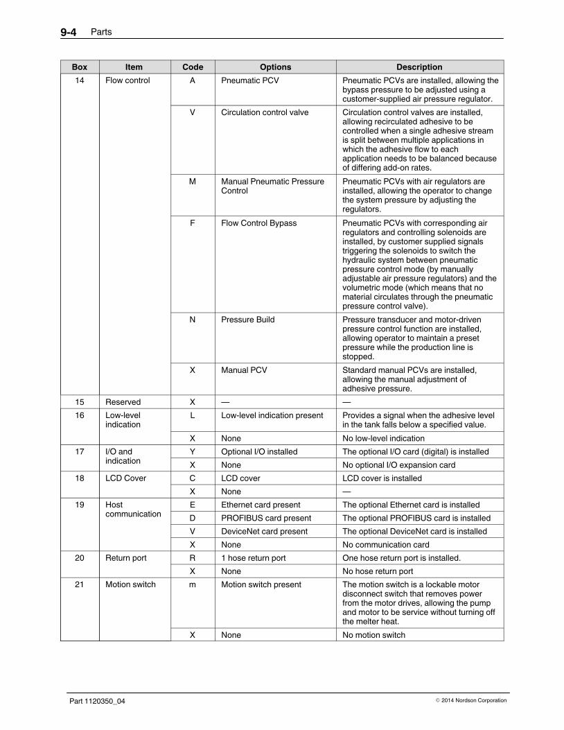
Parts9-4
Part 1120350_04 � 2014 Nordson Corporation
DescriptionOptionsCodeItemBox
14 Flow control A Pneumatic PCV Pneumatic PCVs are installed, allowing thebypass pressure to be adjusted using acustomer‐supplied air pressure regulator.
V Circulation control valve Circulation control valves are installed,allowing recirculated adhesive to becontrolled when a single adhesive streamis split between multiple applications inwhich the adhesive flow to eachapplication needs to be balanced becauseof differing add‐on rates.
M Manual Pneumatic PressureControl
Pneumatic PCVs with air regulators areinstalled, allowing the operator to changethe system pressure by adjusting theregulators.
F Flow Control Bypass Pneumatic PCVs with corresponding airregulators and controlling solenoids areinstalled, by customer supplied signalstriggering the solenoids to switch thehydraulic system between pneumaticpressure control mode (by manuallyadjustable air pressure regulators) and thevolumetric mode (which means that nomaterial circulates through the pneumaticpressure control valve).
N Pressure Build Pressure transducer and motor-drivenpressure control function are installed,allowing operator to maintain a presetpressure while the production line isstopped.
X Manual PCV Standard manual PCVs are installed,allowing the manual adjustment ofadhesive pressure.
15 Reserved X — —
16 Low‐levelindication
L Low‐level indication present Provides a signal when the adhesive levelin the tank falls below a specified value.
X None No low‐level indication
17 I/O andindication
Y Optional I/O installed The optional I/O card (digital) is installed
X None No optional I/O expansion card
18 LCD Cover C LCD cover LCD cover is installed
X None —
19 Hostcommunication
E Ethernet card present The optional Ethernet card is installed
D PROFIBUS card present The optional PROFIBUS card is installed
V DeviceNet card present The optional DeviceNet card is installed
X None No communication card
20 Return port R 1 hose return port One hose return port is installed.
X None No hose return port
21 Motion switch m Motion switch present The motion switch is a lockable motordisconnect switch that removes powerfrom the motor drives, allowing the pumpand motor to be service without turning offthe melter heat.
X None No motion switch

Parts 9-5
Part 1120350_04� 2014 Nordson Corporation
DescriptionOptionsCodeItemBox
22 Sensor type N 120‐ohm nickel sensors Requires Nordson T‐style hose/applicatorconnectors
P 100‐ohm platinum sensors Requires Nordson M‐style hose/applicatorconnectors
23-25 Reserved X — —

Parts9-6
Part 1120350_04 � 2014 Nordson Corporation
Frame Assembly The frame assembly parts vary depending on the size of the melter:one/two‐pump or three/four‐pump. Refer to the correct parts list for yourmelter.
One/Two‐Pump Melter Frame Parts
See Figure 9‐1.
Item Part Description Quantity Note
Module, Common,15/30L, 2D, AT
901 � Panel Assembly,Tank Side,15 AND 30 Liter 2
902 � Panel Assembly,Motor Cover,Side 2
903 � Panel Assembly,Motor Cover Front 1
904 � Panel Assembly ,Electrical Cover Front 1
906 � Rivet, Pop, 1/8X.187,BLK,ALUM 8
907 � Plug, Button, M32, Plastic 1
908 � Plate Stamping,160X55 1
913 7403418 � Kit ,Ship with, 2D, ALTA BLUE Touch 1
914 7400868 � Cable Gland, Clamp, M32, 1522mm 1
917 � Plug, Dome, 22.2, Nylon 66, BLK 2
919 � Plug, Button M40, Plastic 1

Parts 9-7
Part 1120350_04� 2014 Nordson Corporation
X
Figure 9-1 One/two‐pump melter frame assembly parts

Parts9-8
Part 1120350_04 � 2014 Nordson Corporation
Three/Four‐Pump Melter Frame Parts
See Figure 9‐2.
Item Part Description Quantity Note
Module, Common, 30/50L, 4D, AT
901 � Panel Assembly, Tank Side, 15 and 30 Liter 2
902 � Panel Assembly, Motor Cover Side 2
903 � Panel Assembly, Motor Cover Front 4D 1
904 � Panel Assembly, Electrical Cover, Front 4D 1
906 � Rivet, Pop, 1/8X.187, BLK, ALUM 8
907 � Plug, Button, M32, Plastic 1
908 � Plate Stamping,160X55 1
913 7403419 � Kit, Ship with, 4D, ALTA BLUE Touch 1
914 7400354 � Cable Gland, Glamp, M32,1825mm 1
917 � Plug, Dome, 22.2, Nylon 66, BLK 4
919 � Plug, Button M40,Plastic 1

Parts 9-9
Part 1120350_04� 2014 Nordson Corporation
Figure 9-2 Three/four‐pump melter frame assembly parts

Parts9-10
Part 1120350_04 � 2014 Nordson Corporation
Reservoir/Manifold Assembly The reservoir/manifold assembly parts vary depending on the size of themelter: one/two‐pump, three/four‐pump. Refer to the correct parts list for yourmelter.
One/Two‐Pump Melter Reservoir/Manifold Parts
See Figure 9‐3.
Item Part Description Quantity Note— ‐ ‐ ‐ ‐ ‐ ‐ ‐ Assembly, manifold/reservoir, one/two pump —
101 ‐ ‐ ‐ ‐ ‐ ‐ ‐ � Base 1
102 ‐ ‐ ‐ ‐ ‐ ‐ ‐ � Manifold assembly 1 A
103 ‐ ‐ ‐ ‐ ‐ ‐ ‐ � Spacer, manifold to base 4
104 ‐ ‐ ‐ ‐ ‐ ‐ ‐ � Plate, insulator, manifold 1
105 ‐ ‐ ‐ ‐ ‐ ‐ ‐ � Support, hydraulics 2
106 ‐ ‐ ‐ ‐ ‐ ‐ ‐ � Washer, lock, split, M8 24
107 ‐ ‐ ‐ ‐ ‐ ‐ ‐ � Washer, flat, narrow, M8 24
108 ‐ ‐ ‐ ‐ ‐ ‐ ‐ � Screw, socket, M8 x 45 4
109 ‐ ‐ ‐ ‐ ‐ ‐ ‐ � Screw, socket, M8 x 25 20
110 ‐ ‐ ‐ ‐ ‐ ‐ ‐ � Nut, hex, M8 16
111 7400293 � Castor, swivel, 100 mm, 130 kg 2
112 7400294 � Castor, swivel, with lock, 100 mm, 130 kg 2
113 256800 � O‐ring, 26 x 2 2
114 7400132 � O‐ring, Viton, 45 x 2 2
115 ‐ ‐ ‐ ‐ ‐ ‐ ‐ � Reservoir, machined 1
116 ‐ ‐ ‐ ‐ ‐ ‐ ‐ � Screw, socket, M8 x 90 6
117 ‐ ‐ ‐ ‐ ‐ ‐ ‐ � Spring washer, 16 mm OD 6
118 7400339 � Plug, M16, O‐ring, Viton 4
119 7400297 � Service kit, heater, 240V, 800W, 1/2 X 13.75 (allmelter manifolds)
3
120 7400569 � Service kit, heater, 240V, 400W, 1/2 X 13.75(one/two pump melter reservoirs)
3
121 ‐ ‐ ‐ ‐ ‐ ‐ ‐ � Washer, flat, oversize, M6, 22 OD 12
122 ‐ ‐ ‐ ‐ ‐ ‐ ‐ � Washer, lock, split, M6 12
123 ‐ ‐ ‐ ‐ ‐ ‐ ‐ � Screw, pan, recessed, M6 x 10 12
124 ‐ ‐ ‐ ‐ ‐ ‐ ‐ � Screw, pan, recessed, M3 x 8 2
125 ‐ ‐ ‐ ‐ ‐ ‐ ‐ � Lock washer, external, M3 2
126 7401366 � Thermoswitch, AltaBlue 1
127 ‐ ‐ ‐ ‐ ‐ ‐ ‐ � Deflector, adhesive 1
128 1058990 � Cordstock, 3 mm OD, Viton, 75 D 1
129 900298 � Compound, heat sink, 5 oz tube 1
130 900344 � Lubricant, Never Seez, 8 oz can 1
131 900223 � Lubricant, O‐ring, Parker, 4 oz 1
132 900413 � Sealant, RTV, red, 2.8 oz. tube 1
NOTE A: Refer to Manifold Parts.

Parts 9-11
Part 1120350_04� 2014 Nordson Corporation
Figure 9-3 One/two‐pump melter reservoir/manifold assembly parts (30L, 2 SS assembly shown)

Parts9-12
Part 1120350_04 � 2014 Nordson Corporation
Three/Four‐Pump Melter Reservoir/Manifold Parts
See Figure 9‐4.
Item Part Description Quantity Note— - - - - - - - Assembly, manifold/reservoir, three/four pump —
101 - - - - - - - � Base 1
102 - - - - - - - � Manifold assembly 2 A
103 - - - - - - - � Spacer, manifold/base 8
104 - - - - - - - � Plate, insulator, manifold 2
105 - - - - - - - � Support, manifold 1
106 - - - - - - - � Washer, lock, split, M8 12
107 - - - - - - - � Washer, flat, narrow, M8 12
108 - - - - - - - � Screw,socket, M8 x 45 8
109 - - - - - - - � Screw,socket, M8 x 25 4
110 - - - - - - - � Screw, socket, M10 x 25 16
111 7400478 � Castor, swivel, 100 mm, 280 kg 2
112 7400479 � Castor, swivel, with lock, 100 mm, 280 kg 2
113 256800 � O‐ring, 26 x 2 4
114 7400132 � O‐ring, Viton, 45 x 2 4
115 - - - - - - - � Reservoir, machined 1
116 - - - - - - - � Screw, socket, M8 x 100 12
117 - - - - - - - � Spring washer, 16 mm OD 12
119 7400297 � Service kit, heater, 240V, 800W, 1/2 X 13.75 (allmelter manifolds)
6
120 7400874 � Service kit, heater, 240V, 800W, 1/2 X 27.5(three/four pump melter and 100L melterreservoirs)
3
121 - - - - - - - � Washer, flat, oversize, M6, 22 OD 18
123 - - - - - - - � Screw, pan, recessed, M6 x 10 18
124 - - - - - - - � Screw, pan, recessed, M3 x 8 2
125 - - - - - - - � Lock washer, external, M3 2
126 7401366 � Thermoswitch, AltaBlue 1
127 - - - - - - - � Plate deflector 2
128 1058990 � Cordstock, 3 mm OD, Viton, 75 D 2.4
129 900298 � Compound, heat sink, 5 oz tube 1
130 900344 � Lubricant, Never Seez, 8 oz can 1
131 900223 � Lubricant, O‐ring, Parker, 4 oz 1
132 900413 � Sealant, RTV, red, 2.8 oz. tube 1
133 - - - - - - - � Washer, lock, split, M10 16
134 - - - - - - - � Washer, flat, M10 16
136 - - - - - - - � Tag, pump number 2
137 - - - - - - - � Rivet, pop, 1/8 x 0.187 16
NOTE A: Refer to Manifold Parts.

Parts 9-13
Part 1120350_04� 2014 Nordson Corporation
Figure 9-4 Three/four‐pump melter reservoir/manifold assembly parts (30/50L, 2SS/2SS assembly shown)

Parts9-14
Part 1120350_04 � 2014 Nordson Corporation
100L Melter Reservoir/Manifold Parts See Figure 9-5.
Item Part Description Quantity Note— - - - - - - - Assembly, manifold/reservoir, 100L —
101 - - - - - - - � Base 1102 - - - - - - - � Manifold assembly 1 A103 - - - - - - - � Spacer, manifold/base 8104 - - - - - - - � Plate, insulator, manifold 2105 - - - - - - - � Support, manifold 1106 - - - - - - - � Washer, lock, split, M8 12107 - - - - - - - � Washer, flat, narrow, M8 12108 - - - - - - - � Screw,socket, M8 x 45 8109 - - - - - - - � Screw,socket, M8 x 25 4110 - - - - - - - � Screw, socket, M10 x 25 16111 7400478 � Castor, swivel, 100 mm, 280 kg 2112 7400479 � Castor, swivel, with lock, 100 mm, 280 kg 2113 256800 � O-ring, 26 x 2 4−8114 7400132 � O-ring, Viton, 45 x 2 4115 - - - - - - - � Reservoir, machined 1116 - - - - - - - � Screw, socket, M8 x 100 12117 - - - - - - - � Spring washer, 16 mm OD 12119 7400297 � SERVICE KIT, HEATER, 240V, 800W, 1/2 X
13.75 (all melter manifolds)6
120 7400874 � SERVICE KIT, HEATER, 240V, 800W, 1/2 X27.5 (three/four pump melter and 100L melterreservoirs)
6
121 - - - - - - - � Washer, flat, oversize, M6, 22 OD 18123 - - - - - - - � Screw, pan, recessed, M6 x 10 18124 - - - - - - - � Screw, pan, recessed, M3 x 8 2125 - - - - - - - � Lock washer, external, M3 2126 7401366 � THERMOSWITCH, ALTABLUE 1127 - - - - - - - � Plate deflector 1128 1058990 � Cordstock, 3 mm OD, Viton, 75 D 2.5129 900298 � Compound, heat sink, 5 oz tube 1130 900344 � Lubricant, Never Seez, 8 oz can 1131 900223 � Lubricant, O-ring, Parker, 4 oz 1132 900413 � Sealant, RTV, red, 2.8 oz. tube 1133 - - - - - - - � Washer, lock, split, M10 16134 - - - - - - - � Washer, flat, M10 16135 - - - - - - - � Manifold assembly, 2 SS 1 A136 - - - - - - - � Tag, pump number 2137 - - - - - - - � Rivet, pop, 1/8 x 0.187 16
NOTE A: Refer to Manifold Parts.

Parts 9-15
Part 1120350_04� 2014 Nordson Corporation
104
106, 107, 108, 130
106, 107, 109, 130
133, 134, 110112
114, 131
111
116, 117, 129
115
129, 117, 116
129, 117, 138
119, 129
120, 129
109, 107, 106
130, 123, 121
127
129, 126
125, 124
132, 128
136, 137
139, 140, 141
142
103
102
101
143, 107, 106
130, 123, 121
135
113, 131
118, 130
144, 130
105
Figure 9-5 100L melter reservoir/manifold assembly parts (2 DS/2 SS assembly shown)

Parts9-16
Part 1120350_04 � 2014 Nordson Corporation
Manifold Parts
See Figures 9‐6 through 9‐8.
Item Part Description Quantity Note
— ‐ ‐ ‐ ‐ ‐ ‐ ‐ Assembly, manifold/reservoir —
1
‐ ‐ ‐ ‐ ‐ ‐ ‐ � Manifold, 2 Dual Stream, DURA 1
‐ ‐ ‐ ‐ ‐ ‐ ‐ � Manifold, 1 Single Stream, DURA 1
‐ ‐ ‐ ‐ ‐ ‐ ‐ � Manifold, 2 Single Stream, DURA 1
2 ‐ ‐ ‐ ‐ ‐ ‐ ‐ � O-ring 12X2 Viton B 1,2 or 4
3
‐ ‐ ‐ ‐ ‐ ‐ ‐ � Plate, Drain, 2DS 1
‐ ‐ ‐ ‐ ‐ ‐ ‐ � Plate, Drain, 1SS 1
‐ ‐ ‐ ‐ ‐ ‐ ‐ � Plate, Drain, 2SS 1
4 ‐ ‐ ‐ ‐ ‐ ‐ ‐ � SCR, SKT, M6X25,BL 10
5 ‐ ‐ ‐ ‐ ‐ ‐ ‐ � Washer, LK, M, SPT, M6, STL, ZN 10
6 ‐ ‐ ‐ ‐ ‐ ‐ ‐ � Washer, FLT, M, Narrow, M6, STL, ZN 10
7 973480 � Plug, O-ring, STD THD, M14X1.5 8
8 7400339 � Plug, M16 ,O-ring,Viton 6 or 8
9 7400340 � Plug, M22,O-ring,Viton 3 or 6
10 7400341 � Adapter, M22 TO M16, O-ring Port 2 or 4
11 7400355 � O-ring, Viton,FOR M22 O-ring Plug 2 or 4
12 900223 � Lubricant, O-ring, Parker, 4 OZ, 30122‐5 0.02
13 900344 � Lubricant, Never Seez, 8oz can 0.01

Parts 9-17
Part 1120350_04� 2014 Nordson Corporation
12
01
03
05
06
08
02 12
APPLY 0.5−0.7 Nm TORQUE
1208
12
04 13
07 12
08
APPLY 35−40 Nm TORQUE
APPLY 35−40 Nm TORQUE
Figure 9-6 Manifold assembly parts—one or two dual stream pump

Parts9-18
Part 1120350_04 � 2014 Nordson Corporation
Manifold Parts (contd)
1208
04 13
07 12
06
APPLY 55−60 Nm TORQUE
08
05
03
1211
09 12
01
09 12
02 12
10 12 APPLY 35−40 Nm TORQUE
APPLY 0.5−0.7 nm TORQUE
APPLY 35−40 Nm TORQUE
APPLY 55−60 Nm TORQUE
APPLY 35−40 Nm TORQUE
APPLY 55−60 Nm TORQUE
Figure 9-7 Manifold assembly parts - one single stream pump

Parts 9-19
Part 1120350_04� 2014 Nordson Corporation
13
07 12
08 12
01
08
05
06
03
12
1208
1211
09 12
1209
09 12
02 12
10
04
APPLY 55−60 Nm TORQU
APPLY 0.5−0.7 Nm TORQ
APPLY 35−40 Nm TORQU
APPLY 55−60 Nm TORQUE
APPLY 35−40 Nm TORQU
APPLY 35−40 Nm TORQUE
APPLY 55−60 Nm TORQUE
APPLY 55−60 Nm TORQUE
APPLY 35−40 Nm TORQUE
Figure 9-8 Manifold assembly parts—two single‐stream pumps

Parts9-20
Part 1120350_04 � 2014 Nordson Corporation
Hopper Assembly The hopper assembly parts vary depending on the size of the melter:one/two‐pump, three/four‐pump. Refer to the correct parts list for your melter.
One/Two‐Pump Melter Hopper Parts
See Figure 9‐9.
Item Part Description Quantity Note
— ‐ ‐ ‐ ‐ ‐ ‐ ‐ Assembly, hopper, one/two pump —
201 ‐ ‐ ‐ ‐ ‐ ‐ ‐ � Hopper/grid, machined 1
202 ‐ ‐ ‐ ‐ ‐ ‐ ‐ � Washer, flat, narrow, M6 20
203 ‐ ‐ ‐ ‐ ‐ ‐ ‐ � Washer, lock split, M6 40
204 ‐ ‐ ‐ ‐ ‐ ‐ ‐ � Screw, socket, M6 x 25 20
2057400135 � Gasket, hopper, 30L/50L, one/two pump 1
7400134 � Gasket, hopper, 15L, one/two pump 1
206 ‐ ‐ ‐ ‐ ‐ ‐ ‐ � Screw, pan, recessed, M3 x 8 2
207 ‐ ‐ ‐ ‐ ‐ ‐ ‐ � Lock washer, external, M3 2
208 7401366 � Thermoswitch, ALTABLUE 1
209
7400298� Service Kit, Heater, 240V, 800W, 1/2 X 11.65
(one/two pump melter 30/50L hopper)4 or 8
7400876� Service Kit, Heater, 240V, 500W, 1/2 X 6.38
(two‐pump hopper)4
210 ‐ ‐ ‐ ‐ ‐ ‐ ‐ � Washer, flat, oversize, M6, 22 OD 8
211 ‐ ‐ ‐ ‐ ‐ ‐ ‐ � Screw, socket, M6 x 10 8
212 ‐ ‐ ‐ ‐ ‐ ‐ ‐ � Frame, tank, paint 2
213 ‐ ‐ ‐ ‐ ‐ ‐ ‐ � Washer, flat, regular, M6 12
214 ‐ ‐ ‐ ‐ ‐ ‐ ‐ � Nut, hex, M6 12
215 ‐ ‐ ‐ ‐ ‐ ‐ ‐ � Washer, flat, regular, M8 4
216 ‐ ‐ ‐ ‐ ‐ ‐ ‐ � Washer, lock, split, M8 4
217 ‐ ‐ ‐ ‐ ‐ ‐ ‐ � Nut, hex, M8 4
218 ‐ ‐ ‐ ‐ ‐ ‐ ‐ � Panel, rear, hydraulic 1
219 ‐ ‐ ‐ ‐ ‐ ‐ ‐ � Panel, front, hydraulic 1
220 ‐ ‐ ‐ ‐ ‐ ‐ ‐ � Bracket, heater terminal 1
221 ‐ ‐ ‐ ‐ ‐ ‐ ‐ � Screw, flat, socket, M4 x 12 2
222 ‐ ‐ ‐ ‐ ‐ ‐ ‐ � Heater, terminal block assembly 1
223 ‐ ‐ ‐ ‐ ‐ ‐ ‐ � Washer, flat, regular, M5 6
224 ‐ ‐ ‐ ‐ ‐ ‐ ‐ � Washer, lock split, M5 6
225 ‐ ‐ ‐ ‐ ‐ ‐ ‐ � Nut, hex, M5 2
226 ‐ ‐ ‐ ‐ ‐ ‐ ‐ � Panel, top, hydraulic 1
227 ‐ ‐ ‐ ‐ ‐ ‐ ‐ � Lid, outer 1
228 ‐ ‐ ‐ ‐ ‐ ‐ ‐ � Lid, inner 1
229 ‐ ‐ ‐ ‐ ‐ ‐ ‐ � Screw, pan, slotted, M3 x 6 8
Continued...
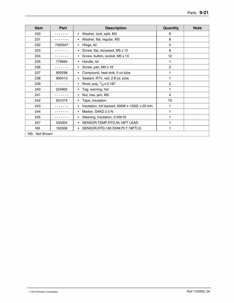
Parts 9-21
Part 1120350_04� 2014 Nordson Corporation
NoteQuantityDescriptionPartItem
230 ‐ ‐ ‐ ‐ ‐ ‐ ‐ � Washer, lock, split, M3 8
231 ‐ ‐ ‐ ‐ ‐ ‐ ‐ � Washer, flat, regular, M3 8
232 7400047 � Hinge, lid 2
233 ‐ ‐ ‐ ‐ ‐ ‐ ‐ � Screw, flat, recessed, M5 x 12 8
234 ‐ ‐ ‐ ‐ ‐ ‐ ‐ � Screw, button, socket, M5 x 10 12
235 779664 � Handle, lid 1
236 ‐ ‐ ‐ ‐ ‐ ‐ ‐ � Screw, pan, M5 x 16 2
237 900298 � Compound, heat sink, 5 oz tube 1
238 900413 � Sealant, RTV, red, 2.8 oz. tube 1
239 ‐ ‐ ‐ ‐ ‐ ‐ ‐ � Rivet, pop, 1/8 x 0.187 2
240 224905 � Tag, warning, hot 1
241 ‐ ‐ ‐ ‐ ‐ ‐ ‐ � Nut, hex, jam, M5 4
242 931074 � Tape, insulation 75
243 ‐ ‐ ‐ ‐ ‐ ‐ ‐ � Insulation, foil backed, 600W x 1200L x 25 mm 1
244 ‐ ‐ ‐ ‐ ‐ ‐ ‐ � Marker, SAKD 2.5 N 1
245 ‐ ‐ ‐ ‐ ‐ ‐ ‐ � Sleeving, insulation, 0.500 ID 1
257 333304 � SENSOR,TEMP,RTD,NI,18FT LEAD 1
NS 162506 � SENSOR,RTD,100 OHM,PLT,18FTLG 1
NS: Not Shown

Parts9-22
Part 1120350_04 � 2014 Nordson Corporation
One/Two‐Pump Melter Hopper Parts (contd)
Figure 9-9 One/two‐pump melter hopper assembly parts (30L hopper without hose return shown)

Parts 9-23
Part 1120350_04� 2014 Nordson Corporation
This page intentionally left blank.

Parts9-24
Part 1120350_04 � 2014 Nordson Corporation
Three/Four‐Pump Melter Hopper Parts
See Figure 9‐10.
Item Part Description Quantity Note
— ‐ ‐ ‐ ‐ ‐ ‐ ‐ Assembly, hopper, three/four pump —
201 ‐ ‐ ‐ ‐ ‐ ‐ ‐ � Hopper, machined 1
202 ‐ ‐ ‐ ‐ ‐ ‐ ‐ � Washer, flat, narrow, M6 30
203 ‐ ‐ ‐ ‐ ‐ ‐ ‐ � Washer, lock, split, M6 66
204 ‐ ‐ ‐ ‐ ‐ ‐ ‐ � Screw, socket, M6 x 25 30
205 7400326 � Gasket, hopper, three/four pump, 50L 1
NS 7400327 � Gasket, hopper, three/four pump, 30L 1
206 ‐ ‐ ‐ ‐ ‐ ‐ ‐ � Screw, pan, recessed, M3 x 8 2
207 ‐ ‐ ‐ ‐ ‐ ‐ ‐ � Lock washer, external, M3 2
208 7401366 � Thermoswitch, ALTABLUE 1
209 7400875 � Service Kit, Heater, 240V, 750W, 1/2 x 11.85(50L�hopper)
9
NS 7400876 � Service Kit, Heater, 240V, 500W, 1/2 X 6.38(30L�hopper)
9
210 ‐ ‐ ‐ ‐ ‐ ‐ ‐ � Washer, flat, oversize, M6, 22 OD 18
211 ‐ ‐ ‐ ‐ ‐ ‐ ‐ � Screw, socket, M6 x 10 18
212 ‐ ‐ ‐ ‐ ‐ ‐ ‐ � Frame, tank, paint 2
213 ‐ ‐ ‐ ‐ ‐ ‐ ‐ � Washer, flat, regular, M6 18
214 ‐ ‐ ‐ ‐ ‐ ‐ ‐ � Nut, hex, M6 12
215 ‐ ‐ ‐ ‐ ‐ ‐ ‐ � Washer, flat, regular, M8 4
216 ‐ ‐ ‐ ‐ ‐ ‐ ‐ � Washer, lock, split, M8 4
217 ‐ ‐ ‐ ‐ ‐ ‐ ‐ � Screw, socket, M8 x 20 4
218 ‐ ‐ ‐ ‐ ‐ ‐ ‐ � Panel, rear, hydraulic 1
219 ‐ ‐ ‐ ‐ ‐ ‐ ‐ � Panel, front, hydraulic 1
220 ‐ ‐ ‐ ‐ ‐ ‐ ‐ � Bracket, heater terminal 2
221 ‐ ‐ ‐ ‐ ‐ ‐ ‐ � Screw, flat, socket, M4 x 12 4
222 ‐ ‐ ‐ ‐ ‐ ‐ ‐ � Heater, terminal block, left 1
223 ‐ ‐ ‐ ‐ ‐ ‐ ‐ � Washer, flat, regular, M5 8
224 ‐ ‐ ‐ ‐ ‐ ‐ ‐ � Washer, lock, split, M5 8
225 ‐ ‐ ‐ ‐ ‐ ‐ ‐ � Nut, hex, M5 4
226 ‐ ‐ ‐ ‐ ‐ ‐ ‐ � Panel, top, hydraulic 1
227 ‐ ‐ ‐ ‐ ‐ ‐ ‐ � Lid, outer 1
228 ‐ ‐ ‐ ‐ ‐ ‐ ‐ � Lid, inner 1
229 ‐ ‐ ‐ ‐ ‐ ‐ ‐ � Screw, pan, split, M3 x 6 8
230 ‐ ‐ ‐ ‐ ‐ ‐ ‐ � Washer, lock, split, M3 8
231 ‐ ‐ ‐ ‐ ‐ ‐ ‐ � Washer, flat, regular, M3 8
232 7400047 � Hinge, lid 2
233 ‐ ‐ ‐ ‐ ‐ ‐ ‐ � Screw, flat, recessed, M5 x 12 8
234 ‐ ‐ ‐ ‐ ‐ ‐ ‐ � Screw, button,socket, M5 x 10 12

Parts 9-25
Part 1120350_04� 2014 Nordson Corporation
Item Part Description Quantity Note
235 779664 � Handle, lid 1
236 ‐ ‐ ‐ ‐ ‐ ‐ ‐ � Screw, pan, M5 x 16 2
237 900298 � Compound, heat sink,5 oz tube 1
238 900413 � Sealant, RTV, red, 2.8 oz tube 1
239 ‐ ‐ ‐ ‐ ‐ ‐ ‐ � Rivet, pop, 1/8 x 0.187 2
240 224905 � Tag, warning, hot 1
241 ‐ ‐ ‐ ‐ ‐ ‐ ‐ � Nut, hex, jam, M5 4
242 931074 � Tape, insulation 200
243 ‐ ‐ ‐ ‐ ‐ ‐ ‐ � Insulation, foil backed, 600W x 1200 L x 25 mm 1
245 ‐ ‐ ‐ ‐ ‐ ‐ ‐ � Sleeving, insulation, 0.500 ID 1
246 7400540 � O‐ring, Viton, 51.5 x 2.65 1
247 ‐ ‐ ‐ ‐ ‐ ‐ ‐ � Plate, machined, hose return 1
248 ‐ ‐ ‐ ‐ ‐ ‐ ‐ � Screw, socket, M6 x 20 6
249 7400337 � Fitting, hose,45deg, M16x9/16‐18, O‐ring, Viton 1
250 ‐ ‐ ‐ ‐ ‐ ‐ ‐ � Heater, terminal block assembly, 400V,three/four‐pump, WYE
1
257 333304 � SENSOR,TEMP,RTD,NI,18FT LEAD 1
NS 162506 � SENSOR,RTD,100 OHM,PLT,18FTLG 1
NS: Not Shown

Parts9-26
Part 1120350_04 � 2014 Nordson Corporation
Three/Four‐Pump Melter Hopper Parts (contd)
Figure 9-10 Three/four‐pump melter hopper assembly parts (50L hopper with hose return shown)

Parts 9-27
Part 1120350_04� 2014 Nordson Corporation
This page intentionally left blank.

Parts9-28
Part 1120350_04 � 2014 Nordson Corporation
100L Melter Hopper Parts See Figure 9-11.
Item Part Description Quantity Note— - - - - - - - Assembly, hopper, 100L —
201 - - - - - - - � Hopper, machined 1202 - - - - - - - � Washer, flat, narrow, M6 38203 - - - - - - - � Washer, lock, split, M6 74204 - - - - - - - � Screw, socket, M6 x 25 38205 7400901 � Gasket, hopper, 100L 1206 - - - - - - - � Screw, pan, recessed, M3 x 8 2207 - - - - - - - � Lock washer, external, M3 2208 7401366 � THERMOSWITCH, ALTABLUE 1209 7401316 � Heater, 240V, 1000W, 0.50 D x 22.75 long 9210 - - - - - - - � Washer, flat, oversize, M6, 22 OD 18211 - - - - - - - � Screw, socket, M6 x 10 18212 - - - - - - - � Frame, tank, paint 2213 - - - - - - - � Washer, flat, regular, M6 18214 - - - - - - - � Nut, hex, M6 12215 - - - - - - - � Washer, flat, regular, M8 4216 - - - - - - - � Washer, lock, split, M8 4217 - - - - - - - � Screw, socket, M8 x 20 4218 - - - - - - - � Panel, rear, hydraulic 1219 - - - - - - - � Panel, front, hydraulic 1220 - - - - - - - � Bracket, heater terminal 2221 - - - - - - - � Screw, flat, socket, M4 x 12 4222 - - - - - - - � Heater, terminal block, left 1223 - - - - - - - � Washer, flat, regular, M5 8224 - - - - - - - � Washer, lock, split, M5 8225 - - - - - - - � Nut, hex, M5 4226 - - - - - - - � Panel, top, hydraulic 1227 - - - - - - - � Lid, outer 1228 - - - - - - - � Lid, inner 1229 - - - - - - - � Screw, pan, split, M3 x 6 8230 - - - - - - - � Washer, lock, split, M3 8231 - - - - - - - � Washer, flat, regular, M3 8232 7400047 � Hinge, lid 2233 - - - - - - - � Screw, flat, recessed, M5 x 12 8235 779664 � Handle, lid 1236 - - - - - - - � Screw, pan, M5 x 16 2237 900298 � Compound, heat sink,5 oz tube 1238 900413 � Sealant, RTV, red, 2.8 oz tube 1239 - - - - - - - � Rivet, pop, 1/8 x 0.187 2240 224905 � Tag, warning, hot 1241 - - - - - - - � Nut, hex, jam, M5 4242 931074 � Tape, insulation 260243 - - - - - - - � Insulation, foil backed, 600W x 1200 L x 25 mm 1245 - - - - - - - � Sleeving, insulation, 0.500 ID 1246 7400540 � O-ring, Viton, 51.5 x 2.65 1

Parts 9-29
Part 1120350_04� 2014 Nordson Corporation
NoteQuantityDescriptionPartItem247 - - - - - - - � Plate, machined, hose return 1248 - - - - - - - � Screw, socket, M6 x 20 6249 7400337 � Fitting, hose,45 degree, M16 x 9/16-18, O-ring,
Viton1
250 - - - - - - - � Heater, terminal block, right 1
257 333304 � SlENSOR,TEMP,RTD,NI,18FT LEAD 1
NS 162506 � lSENSOR,RTD,100 OHM,PLT,18FTLG 1
NS: Not Shown
Figure 9-11 100L melter hopper assembly parts (100L hopper with hose return shown)

Parts9-30
Part 1120350_04 � 2014 Nordson Corporation
Pump Assemblies The pump assembly parts vary depending on the type of pump:single‐stream or dual‐stream. Refer to the correct parts lists for your melter.
Pump Module Parts
See Figure 9‐12.
Item Part Description Quantity Note
— ‐ ‐ ‐ ‐ ‐ ‐ Assembly, pump module —
301 256800 � O‐ring, 26 x 2 1
302 250269 � O‐ring, 35 x 2 1
303‐ ‐ ‐ ‐ ‐ ‐ � Adapter assembly, single‐stream, with shutoff 1 A
‐ ‐ ‐ ‐ ‐ ‐ � Adapter assembly, dual‐stream, with shutoff 1 B
304 ‐ ‐ ‐ ‐ ‐ ‐ � Spring washer,16 mm OD 4
305 ‐ ‐ ‐ ‐ ‐ ‐ � Screw, socket, M8 x 110 4
306‐ ‐ ‐ ‐ ‐ ‐ � Gear pump, single‐stream 1 C
‐ ‐ ‐ ‐ ‐ ‐ � Gear pump, dual‐stream 1 D
308 900344 � Lubricant, Never Seez, 8 oz can 1
309 900223 � Lubricant, O‐ring, Parker, 4 oz 1
NOTE A: Refer to Single‐Stream Pump Adapter Parts.
B: Refer to Dual‐Stream Pump Adapter Parts.
C: Refer to Single‐Stream Gear Pumps for pump part numbers.
D: Refer to Dual‐Stream Gear Pumps for pump part numbers.
NS: Not Shown

Parts 9-31
Part 1120350_04� 2014 Nordson Corporation
THIS V IEW SHOW S THE SINGLE STREAM PUMP
THIS V IEW SHOW S THE DUAL STREAM PUMP
309, 302
303304 309, 302
309, 301
TIGHTEN SCREWS20 TO 25 N−M306, 307, 308 305, 308 304 303
309, 301
306, 307, 308 305, 308
TIGHTEN SCREWS20 TO 25 N−M
THIS VIEW SHOWS THE BLANK
308, 305304303
302, 309
309, 301
Figure 9-12 Pump module parts

Parts9-32
Part 1120350_04 � 2014 Nordson Corporation
Single‐Stream Pump Adapter Parts
See Figure 9‐13.
Item Part Description Quantity Note
7402910 Kit, Service, Adapter, SSN
7402911 Kit, Service, Adapter, SSN,
7402914 Kit, Service, Adapter, SSF
01 Adapter, pump, singlestream 1
02 Valve, rotary 1
03 Plate, stop 1
04 Screw, socket, M5 x 12 4
05 Washer, flat, narrow, M5 4
06 Washer, lock, split, M5 4
07 207932 Valve, safety 1 A
08 973480 Plug, Oring, straightthread, M14 x 1.5 4
09 900223 Lubricant, Oring, Parker, 4 oz 1
10 900341 Lubricant, NeverSeez, 16 oz cans 1
12 250267 Oring, 32 x 2 1
13 985022 Pin, dowel, M6 x 20 long, hose and applicator 1
NOTE A: Refer to Safety Valve Parts.
08 10
1007
10040605
01
1209
08 10
03
13
02
Figure 9-13 Single‐stream pump adapter parts

Parts 9-33
Part 1120350_04� 2014 Nordson Corporation
Dual‐Stream Pump Adapter Parts
See Figure 9‐14.
Item Part Description Quantity Note
7402909 Kit, Service, Adapter, DSN
7402913 Kit, Service, Adapter, DSF
01 � Adapter, pump, dualstream 1
02 � Valve, rotary 1
03 � Plate, stop 1
04 � Screw, socket, M5 x 12 4
05 � Washer, flat, narrow, M5 4
06 � Washer, lock, split, M5 4
07 207932 � Valve, safety 2 A
08 973480 � Plug, Oring, straightthread, M14 x 1.5 5
09 900223 � Lubricant, Oring, Parker, 4 oz 1
10 900341 � Lubricant, NeverSeez, 16 oz cans 1
11 973459 � Plug, Oring, straightthread, M22 x 1.5 1
12 250267 � Oring, 32 x 2 1
13 985022 � Pin, dowel, M6 x 20 long, hose and applicator 1
01
02
03
05 06 04
13
09 12
11 10
0810
10
07 10
08 10
08 10
0810
Figure 9-14 Dual‐stream pump adapter parts

Parts9-34
Part 1120350_04 � 2014 Nordson Corporation
Single‐Stream Gear Pumps
See Figure 9‐15.
Item GlandSeal Part
VarisealPart
Description Quantity Note
— 259598 7109715 Gear pump SN0030 (0.30 cc/rev) 1
— 254406 729105 Gear pump SN0046 (0.46 cc/rev) 1
— 257734 7116270 Gear pump SN0062 (0.62 cc/rev) 1
— 256015 7104514 Gear pump SN0093 (0.93 cc/rev) 1
— 254316 203708 Gear pump SN0186 (1.86 cc/rev) 1
— 254247 729106 Gear pump SN0371 (3.71 cc/rev) 1
— 254279 729107 Gear pump SN0773 (7.73 cc/rev) 1
— 254231 7116829 Gear pump SN1710 (17.10 cc/rev) 1
— 253992 7131840 Gear pump SH0773, hardened (7.73 cc/rev) 1
— 259600 7130225 Gear pump SH0371, hardened (3.71 cc/rev) 1
— 394589 Refer toTable 9‐1
Service Kit for gland seal pump sizes SN0030 to SN0773
1
— ‐ ‐ ‐ ‐ ‐ — � O‐ring 10 x 1.5, PTFE 1
— ‐ ‐ ‐ ‐ ‐ — � Sealing paste, Stucarit 203, 100 ml 1
— ‐ ‐ ‐ ‐ ‐ — � High‐temp. grease, GLS 595/N2, 10 g 1
— 394596 Refer toTable 9‐2
Service Kit for gland seal pump size SN1710
1
— ‐ ‐ ‐ ‐ ‐ — � O‐ring 15 x 1.5 1
— ‐ ‐ ‐ ‐ ‐ — � Sealing paste, Stucarit 203, 100 ml 1
— ‐ ‐ ‐ ‐ ‐ — � High‐temp. grease, GLS 595/N2, 10 g 1

Parts 9-35
Part 1120350_04� 2014 Nordson Corporation
Table 9-1 Variseal Pump Service Kits (Except SN1710)
Item Part Description Quantity Note
NS 7136920 Sealing Kit,PUMP F.Shaft D12,7(pump seal service kit)
—
NS ‐ ‐ ‐ ‐ ‐ ‐ � O-ring 22X3 Viton 70 Shore a Black 2
NS ‐ ‐ ‐ ‐ ‐ ‐ � Ring ID 12, 7 1
NS ‐ ‐ ‐ ‐ ‐ ‐ � Turcon-Roto-Variseal D12, 7 Inside Seal 1
NS ‐ ‐ ‐ ‐ ‐ ‐ � Allen Head Cap Screw M5X16 DIN912 A2‐70 3
NS ‐ ‐ ‐ ‐ ‐ ‐ � High-Temp. Grease GLS 595/N2 CAN:10G 1
NS 7146229 � In‐Assembly Tools 7136915, 7136918, EN/GE 1 A
NS 7136915 Assembly Tool F.Shaft Sealing D12,7(assembly tool service kit)
—
NS ‐ ‐ ‐ ‐ ‐ ‐ � Assembly Mandrel F.Shaft Sealing D12, 7 1
NS ‐ ‐ ‐ ‐ ‐ ‐ � Assembly Bushing F.Shaft Sealing D12, 7 1
NS 7146229 � In‐Assembly Tools 7136915, 7136918, EN/GE 1 A
NOTE A: This is instruction may be obtained from http://emanuals.nordson.com, or contact your Nordsonrepresentative.
NS: Not Shown

Parts9-36
Part 1120350_04 � 2014 Nordson Corporation
Single‐Stream Gear Pumps (contd)
Table 9-2 Variseal Pump SN1710 Service Kit
Item Part Description Quantity Note
— 7136921 Sealing Kit, Pump F.Shaft D16(pump seal service kit)
—
NS ‐ ‐ ‐ ‐ ‐ ‐ � O-ring 28X3 Viton 70 Shore A Schwarz 2
NS ‐ ‐ ‐ ‐ ‐ ‐ � Buffer Ring ID 16 1
NS ‐ ‐ ‐ ‐ ‐ ‐ � Turcon‐Roto-Variseal D16 Inside Seal 1
NS ‐ ‐ ‐ ‐ ‐ ‐ � Allen Head Cap Screw M6X20 DIN912 SST 4
NS ‐ ‐ ‐ ‐ ‐ ‐ � High-Temp. Grease GLS 595/N2 CAN:10G 1
— 7136918 Assembly Tool F.Shaft Sealing D16(assembly tool service kit)
— —
NS ‐ ‐ ‐ ‐ ‐ ‐ � Assembly Mandrel F.Shaft Sealing D16 1
NS ‐ ‐ ‐ ‐ ‐ ‐ � Assembly Bushing F.Shaft Sealing D16 1
NS 7146229 � In‐Assembly Tools 7136915, 7136918, EN/GE 1 A
NOTE A: This is instruction may be obtained from http://emanuals.nordson.com, or contact your Nordsonrepresentative.
NS: Not Shown
Figure 9-15 Single‐stream gland seal (left) and Variseal (right) gear pumps

Parts 9-37
Part 1120350_04� 2014 Nordson Corporation
Dual‐Stream Gear Pumps
See Figure 9‐16.
Item GlandSeal Part
VarisealPart
Description Quantity Note
— 291995 7116580 Gear pump DN0030 (2 x 0.30 cc/rev) 1
— 291996 7104179 Gear pump DN0046 (2 x 0.46 cc/rev) 1
— 203640 7104180 Gear pump DN0062 (2 x 0.62 cc/rev) 1
— 403729 7116269 Gear pump DN0093 (2 x 0.93 cc/rev) 1
— 291997 7104181 Gear pump DN0186 (2 x 1.86 cc/rev) 1
— 406435 7116268 Gear pump DN0279 (2 x 2.79 cc/rev) 1
— 7104645 Refer toTable 9‐1
Service Kit for gland seal pump sizes DN0030 to DN0279
1
— ‐ ‐ ‐ ‐ ‐ — � Seal, PU6/12, 94 x 80 x 0.8 2
— ‐ ‐ ‐ ‐ ‐ — � Sealing paste, Stucarit 203, 100 ml 1
— ‐ ‐ ‐ ‐ ‐ — � High‐temp. grease, GLS 595/N2, 10 g 1
Figure 9-16 Dual‐stream gland seal gear pump

Parts9-38
Part 1120350_04 � 2014 Nordson Corporation
Safety Valve Parts
See Figure 9‐17.
Item Part Description Quantity Note
— 207932 Valve, safety, 85 bar 1
— 394592 Service kit 1
1 ‐‐‐‐‐‐ � O‐ring 11 x 2 1
2 ‐‐‐‐‐‐ � O‐ring 9 x 2 1
— ‐‐‐‐‐‐ � High‐temp. Grease, GLS 595/N2, 10g 1
1
2
Figure 9-17 Safety valve parts

Parts 9-39
Part 1120350_04� 2014 Nordson Corporation
This page intentionally left blank.

Parts9-40
Part 1120350_04 � 2014 Nordson Corporation
Control Valve Assemblies The control valve assemblies vary depending on the type of pressure controlvalve: pressure control valve, pneumatic pressure control valve, circulationcontrol valve, or blank. Refer to the correct parts lists for your melter.
Control Valve Module Parts
See Figure 9‐18.
Item Part Description Quantity Note
Assembly,control valve module
401 7104265 � Filter cartridge MW0,2 VB reinf. compl. 1 A
401 � Plug M56x1,5 L35 1
402 203059 � Pressure ctrl valve 590 bar VB/DB 1 B
207300 � Pressure ctrl valve 590 bar VB/DB pneum 1 C
1070961 � Valve, Circulation Control, AltaBlue 1 D
� Plug, pressure regulator valve VB/DB 1
403 � Valve, Ball, 8 MM, SS 316 1
404 � Screw, Drain Valve 1
405 � Retaining Ring,INT,51,Basic 1
NOTE A: Refer to Filter Cartridge Parts.
B: Refer to Pressure Control Valve Parts OR Pressure Build Control.
C: Refer to Pneumatic Pressure Control Valve Parts OR Manual Pneumatic Pressure ControlOR Flow Control Bypass.
D: Refer to Circulation Control Valve Parts.
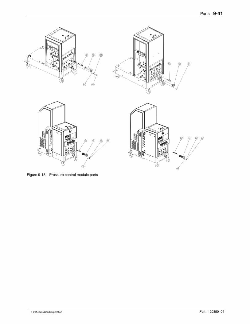
Parts 9-41
Part 1120350_04� 2014 Nordson Corporation
Figure 9-18 Pressure control module parts

Parts9-42
Part 1120350_04 � 2014 Nordson Corporation
Filter Cartridge Parts
See Figure 9‐19.
Item Part Description Quantity Note
— 7104265 Filter cartridge, mesh Size 0.2 mm, complete 1
— 394590 Service Kit Filter 0.2 mm 1
— ‐ ‐ ‐ ‐ ‐ � Filter sleeve Mesh Size 0,2 complete 1
— ‐ ‐ ‐ ‐ ‐ � � Filter sheath D40 1
— ‐ ‐ ‐ ‐ ‐ � � Filter sleeve MS 0,2 L104 1
— ‐ ‐ ‐ ‐ ‐ � � O‐ring 31x1 1
— ‐ ‐ ‐ ‐ ‐ � � O‐ring 44x3 1
— ‐ ‐ ‐ ‐ ‐ � � O‐ring 48x2 1
— ‐ ‐ ‐ ‐ ‐ � High‐temp. grease, GLS 595/N2, 10g 1
Figure 9-19 Filter cartridge parts

Parts 9-43
Part 1120350_04� 2014 Nordson Corporation
Pressure Control Valve Parts
See Figure 9‐20.
Item Part Description Quantity Note
— 203059 Valve, pressure control, adjustable, 90 bar 1
1 ‐ ‐ ‐ ‐ ‐ � Body, valve 1
2 ‐ ‐ ‐ ‐ ‐ � Piston, valve, supporting ring 1
3 ‐ ‐ ‐ ‐ ‐ � Set screw, black, 90 bar 1
4 ‐ ‐ ‐ ‐ ‐ � Compression spring, 2.2 x 7.4 x 34.4 1
5 ‐ ‐ ‐ ‐ ‐ � O‐ring, 6 x 2 1
6 ‐ ‐ ‐ ‐ ‐ � O‐ring, 11 x 2 1
7 ‐ ‐ ‐ ‐ ‐ � O‐ring, 9 x 2 1
8 ‐ ‐ ‐ ‐ ‐ � Supporting ring, Da10, Di6.7, spiral 1
— 394600 Service Kit Pressure control valve 1
6 ‐ ‐ ‐ ‐ ‐ � O‐ring 11 x 2 1
7 ‐ ‐ ‐ ‐ ‐ � O‐ring 9 x 2 1
— ‐ ‐ ‐ ‐ ‐ � High‐temp. grease, GLS 595/N2, 10 g 1
7
3
4
2
8
5
6
1
Figure 9-20 Pressure control valve parts

Parts9-44
Part 1120350_04 � 2014 Nordson Corporation
Pneumatic Pressure Control Valve Parts
See Figure 9‐21.
Item Part Description Quantity Note
207300 Pressure ctrl valve 590 bar VB/DB pneum —
1 � Piston, pressure control valve 1
2 � Valve body, bypass 300 degree 1
3 � Cylinder, bypass pneu., Da19.3 1
4 � Valve, body, bypass pneumatic, 50bar (90 psi) 1
5 � Piston, bypass pneu., Da19.3 1
6 � Piston, bypass pneu., Da19.3 1
7 � Seal, 19.7 x 0.6 1
8 � O-ring, 11 x 2 1
9 � O-ring, 9 x 2 1
10 � Fitting, quick thread-in, -W-d04-G1/8-TURN 1
� Fitting, quick thread-in, -W-d08-R1/8-TURN 1
11 � Inside seal, Turcon-Variseal_M2S 1
— 394600 Service Kit Pressure control valve 1
8 � O-ring, 11 x 2 1
9 � O-ring, 9 x 2 1
— � High temp grease, GLS 595/N2, 10g 1

Parts 9-45
Part 1120350_04� 2014 Nordson Corporation
9
6
7
5
1
118
2
4
3
10
Figure 9-21 Pneumatic pressure control valve parts

Parts9-46
Part 1120350_04 � 2014 Nordson Corporation
Pneumatic Pressure Control Valve Interface Parts
See Figure 9‐23.
Item Part Description Quantity Note1 207300 Valve, pressure control, pneumatic 1 2 - - - - - - - Hose, air‐operated, D4, 0 D2, 5 PTFE 1.5 3 - - - - - - - Fitting, quick‐thread, W‐D04‐G 1/8‐turn 1 4 - - - - - - - Reducer 1 5 - - - - - - - Sealing ring, R1/4‐type, PD 5 6 - - - - - - - T‐piece 1 7 - - - - - - - Nipple, double 1 8 - - - - - - - Bulkhead connection, iG1/4 1 9 - - - - - - - Street el, G1/4 x RP1/4 1
10 279615 Bypass valve 1 11 — Item no. not used — 12 - - - - - - - Sign, max 6.0 1 13 — Item no. not used — 14 - - - - - - - Air coupling, male, AG1/4 L3 1 15 - - - - - - - Air coupling, female, D6 NE7.2 L60 1 16 - - - - - - - Hose, air‐operated, D8.0, D6.0 PU blue 2 17 - - - - - - - Fitting, straight 1 18 - - - - - - - Grease, high‐temperature, GLS 595/N2, can 1
14 5 1218
1 2
3 184 1817 16 56781859 101815
ITEM 10 MUST BE VERTICAL
THIS VALVE CONNECT TO MAINFOLD
Figure 9-22 Pneumatic pressure control valve interface parts

Parts 9-47
Part 1120350_04� 2014 Nordson Corporation
This page intentionally left blank.

Parts9-48
Part 1120350_04 � 2014 Nordson Corporation
Manual Pneumatic Pressure Control Valve Parts
See Figure 9‐23.
Item Part Description Quantity Note
Manual Pneumatic PCV Assembly,4 Path , Touch
1 � Cabinet, Assembly ,Manual Pneumatic PCV,Touch
1
2 � Air Inlet, with Safety Valve, FCB/AOPCV, Touch 1
3 7403318 � Service Kit, pressure regulator, ARM10 4
4 � Pneumatic Connector,3XD042XD6 2
5 � Fitting, Plug, D06 2
6 � Fitting, Plug, D04 2
8 � Multi Plug Connector,4 Fitting 1
9 � Tubing, Polyurethane, 0.6
10 � Tubing, Polyurethane, 0.14
11 � AIE Hose, D4.0,d2.5,PU,BLUE 0.8
12 � AIE Hose, D4.0,d2.5,PU,BLUE 1.8
13 � AIE Hose, D4.0,d2.5,PU,BLUE 1.7
16 � Rivet, #8X11#Nylon 4
17 207300 � Pressure ctrl valve 590 bar VB/DB pneum 4
18 � Heat-Resistant Tube D4 7
19 � Clamp,Wire Routing, D04 8
20 � SCR, SKT, M8X1.25X25,BL 4
21 � Washer, LK, M, EXT,M10, ZN 4
22 � Nut, HEX, Serrated, M8, STL,(8.8)M ZP 4
NOTE: this part list is 4 path option for Manual Pneumatic Pressure Control

Parts 9-49
Part 1120350_04� 2014 Nordson Corporation
Figure 9-23 Manual pneumatic pressure control valve parts

Parts9-50
Part 1120350_04 � 2014 Nordson Corporation
Flow Control Bypass Control Valve Parts
See Figure 9‐24.
Item Part Description Quantity Note
FCB Assembly,4 Path , Touch
1 � Cabinet, Assembly,Flow Control Bypass, Touch 1
2 � Air Inlet, with Safety Valve, FCB/AOPCV, Touch 1
3 7403318 � Service Kit, pressure regulator, ARM10 4
4 � 2/3 Valve,Assembly,14 Unit, FCB, Touch 1
5 � Pneumatic Connector,3XD042XD6 2
6 � Fitting, Plug, D06 1
7 � Fitting, Plug, D04 2
8 � Multi Plug Connector,4 Fitting 1
9 � Tubing, Polyurethane, 0.45
10 � Tubing, Polyurethane, 0.45
11 � Tubing, Polyurethane, 0.14
12 � AIE Hose, D4.0,d2.5,PU,BLUE 0.8
13 � AIE Hose, D4.0,d2.5,PU,BLUE 0.8
14 � AIE Hose, D4.0,d2.5,PU,BLUE 4
18 � Heat-Resistant Tube D4 7
19 � Clamp,Wire Routing, D04 8
20 � Rivet, #8X11#Nylon 4
21 207300 � Pressure ctrl valve 590 bar VB/DB pneum 4
22 � SCR, SKT, M8X1.25X25,BL 4
23 � Washer, LK, M, EXT,M10, ZN 4
24 � Nut, HEX, Serrated, M8, STL,(8.8)M ZP 4
26 � Nut, HEX with EXT TOOTH Washer, M4 4
27 � Wire,0.75SQMM, 24/ 0.20,PVC,RED 4
28 � Wire,0.75SQMM, 24/ 0.20,PVC,BLK 4
NOTE: this part list is 4 path option for Flow Control Bypass

Parts 9-51
Part 1120350_04� 2014 Nordson Corporation
Figure 9-24 Flow control bypass control valve parts

Parts9-52
Part 1120350_04 � 2014 Nordson Corporation
Manual Pneumatic Pressure Control Valve Cabinet
See Figure 9‐25.
Item Part Description Quantity Note
Cabinet, Assembly,Manual Pneumatic PCV, Touch
1 � Cabinet, Manual Pneumatic, FCB, Touch 1
2 � Cover, GUGUE Mounting, FCB, Touch 1
3 � Panel, with Shutter, FCB, Touch 1
4 � Dust Guard Cover 1
7 � SCR, SKT, Low, M4X10, ZN 16
8 � Washer, FLT, M, Narrow, M4, STL, ZN 16
9 � Washer, LK, M, SPT,M4, STL, ZN 16
09�08
08��09
08 09
03
07
01
07
02
04
07
Figure 9-25 Manual pneumatic pressure control valve cabinet parts

Parts 9-53
Part 1120350_04� 2014 Nordson Corporation
This page intentionally left blank.

Parts9-54
Part 1120350_04 � 2014 Nordson Corporation
Flow Control Bypass Control Valve Cabinet
See Figure 9‐26.
Item Part Description Quantity Note
Cabinet, Assembly,Flow Control Bypass, Touch —
1 � Cabinet, Manual Pneumatic, FCB, Touch 1
2 � Cover, GUGUE Mounting, FCB, Touch 1
3 � Panel, with Shutter, FCB, Touch 1
4 � Dust Guard Cover 1
5 � Heavy Connector,Housing, with Cover 1
6 � Heavy Connector,Insert, Female,16 PIN 1
7 � Scr, skt, Low,M4X10, ZN 16
8 � Washer, flt, M, Narrow, M4, STL, ZN 16
9 � Washer, lk, M, SPT,M4, STL, ZN 16
10 � Allen Head Cap Screw M3X10 DIN912 SST 4
11 � Washer, flt, M, REG, M3, Zinc Plate 4
12 � Washer, lk, M, SPT,M3, STL, ZN 4

Parts 9-55
Part 1120350_04� 2014 Nordson Corporation
08
09 08
09
11
09
06
08
12
01
07
10
07
03
07
02
04
05
13
Figure 9-26 Flow control bypass control valve cabinet parts

Parts9-56
Part 1120350_04 � 2014 Nordson Corporation
Manual Pneumatic Pressure & Flow Control Bypass Control ValveInterface Parts
See Figure 9‐27.
Item Part Description Quantity Note
Air Inlet, with Safety Valve, FCB/AOPCV, Touch
1 � quick threadin fitting Gd06G1/40000 1
2 � airoperated hose D8,0 d6,0 PU blue 2
3 � female air coupling d6 NW7,2 L60 1
4 � male air coupling KS41/4A 1
5 � Sealing Ring R1/4 Type:PDR14 2
6 � Bulkhead Connection IG1/4 1
7 � Double Nipple AR1/4AR1/4 1
8 � TPiece 3XIRP1/4 1
9 � Pipeftg,hyd,elbow90street,1/4bsp,brass,n 1
10 � Pneumatic Connector, Type T,Rc1/42XD6 1
11 � Safety Valve 6BAR G1/4 SW20 1
12 � Sign "MAX. 6 BAR" Self Adhesive 1
Figure 9-27 Manual pneumatic pressure & flow control bypass control valve interface parts

Parts 9-57
Part 1120350_04� 2014 Nordson Corporation
Flow Control Bypass Control Valve Solenoid Parts
See Figure 9‐28.
Item Part Description Quantity Note
2/3 Valve,Assembly,14 Unit, FCB, Touch
1 � Fixing Plate,2/3 Valve, AOPCV&FCB 1
2 7403314 � Service kit, Solenoid Valve,2/3,1 Unit 1
� Solenoid Valve,2/3,2 Unit 1
� Solenoid Valve,2/3,3 Unit 1
� Solenoid Valve,2/3,4 Unit 1
3 � Connector,Type I,M5D04 4
4 � Pneumatic Connector,Rc1/84 4
5 � Connector, Male, 6MM 1/8" Thread, BR
Figure 9-28 Flow control bypass control valve solenoid parts

Parts9-58
Part 1120350_04 � 2014 Nordson Corporation
Manual Pneumatic Pressure & Flow Control Bypass Control Valve MultiConnector Parts
See Figure 9‐29.
Item Part Description Quantity Note
Multi Plug Connector —
1 Multi Plug Connector Socket 1
2 Multi Plug Connector Plug 1
3 BARB Fitting Socket
4 BARB Fitting Plug
5 SCR, SKT, Low,M4X10, ZN 4
6 Washer, FLT, M, Narrow, M4, STL, ZN 4
7 Washer, LK, M, SPT,M4, STL, ZN 4
Figure 9-29 Manual pneumatic pressure & flow control bypass control valve multi connector parts

Parts 9-59
Part 1120350_04� 2014 Nordson Corporation
This page intentionally left blank.

Parts9-60
Part 1120350_04 � 2014 Nordson Corporation
Pressure Build Control Parts
Table 9‐3 Internal transducer parts list
Item Part Description Quantity
401 7403137 KIT,FLOW/PRESSURE CONTROL BOARD 1
402 SCR,PAN,SLT,M3X6,ZN 4
403 WASHER,LK,M,INT,M3,STL,ZN 4
1001 TRANSDUCER,PRESSURE,M14X1.5, 0-1500PSI 1
1002 CABLE,PRESSURE,6 PIN,MELTER SIDE,TOUCH 1
1003 CLAMP,D26.5,TRANSDUCER,PRESSURE,ALUM 1
1004 SCR,SKT,M5X16,BL 1
1005 WASHER,LK,M,SPT,M5,STL,ZN 1
1006 MOUNT,SADDLE TIE, DIA.6 2
1007 NUT,HEX,M5,STL,ZN 2
1008 WASHER,FLT,M,REG,M5,STL,ZN 2

Parts 9-61
Part 1120350_04� 2014 Nordson Corporation
1006, 1007 and 1008
401, 402 and 403
1006, 1007 and 1008
1005
1004
10031001
1002
Figure 9‐25 Internal transducer parts

Parts9-62
Part 1120350_04 � 2014 Nordson Corporation
Circulation Control Valve Parts
See Figure 9‐30.
Item Part Description Quantity Note
— 1070961 Valve, circulation control 1
1 ‐ ‐ ‐ ‐ ‐ � Body, circulation valve 1
2 ‐ ‐ ‐ ‐ ‐ � Spool, circulation valve 1
3 ‐ ‐ ‐ ‐ ‐ � Nut, hex, M12 1
4 ‐ ‐ ‐ ‐ ‐ � O‐ring, 9 x 2 1
5 ‐ ‐ ‐ ‐ ‐ � O‐ring, 11 x 2 1
6 ‐ ‐ ‐ ‐ ‐ � O‐ring, Viton, 0.239 ID x 0.070 W 1
7 ‐ ‐ ‐ ‐ ‐ � Screw, set, cup, M4 x 4, stainless‐steel 1
— 394600 Service Kit Circulation control valve 1
4 ‐ ‐ ‐ ‐ ‐ � O‐ring 9 x 2 1
5 ‐ ‐ ‐ ‐ ‐ � O‐ring 11 x 2 1
— ‐ ‐ ‐ ‐ ‐ � High‐temp. grease, GLS 595/N2, 10g 1
1 2
3
4
5
5
7
Figure 9-30 Circulation control valve parts

Parts 9-63
Part 1120350_04� 2014 Nordson Corporation
Flow Control Bypass
This option contains:
a. Pneumatically actuated pressure control valve (1x per stream)
b. Fast switching 3-way solenoid (1x per stream)
c. Pressure gauge (1x per stream – for single stream pumps only)
d. Pressure regulator + gauge (1x per stream)
Set up:
Available line pressure (approx. 6 bar) is being put on the pressure regulatorand into the solenoid input. The outlet pressure of the regulator is adjustedaccording to the desired recirculation flow setting. The pressure gauge isinstalled after the pump into the stream that goes to the hose connectorfitting. The actuation signal for the solenoid is being supplied externally viaconnector and in accordance to the trigger signal of the gun.
Function:
When the gun is open the system is run in volumetric mode, which meansthat no material does circulate through the pneumatic pressure control valve.In this mode the flow is determined by the motor rpm setting, respectively thekey to line signal. To achieve this a trigger signal (e.g. the trigger signal forthe gun) is send to the solenoid for the pneumatic pressure control valve,which does close with maximum air pressure (e.g. available line pressure of6 bar). In cases of overpressure the safety pressure valve would operate.When the gun is closed, a trigger signal (e.g. the trigger signal for the gun)does operate the solenoid for the bypass valve. This allows the regulated(reduced) air flow to open the pneumatic pressure control valve and to adjustrecirculation pressure according to the air pressure setting. The major goal isto reduce/ eliminate the burn-through (hammerhead) effect by adjusting thepressure during gun closed. The gun or nozzle pressure in this mode isusually the same as during gun open.

Parts9-64
Part 1120350_04 � 2014 Nordson Corporation
Schematics
Figure 9-31 Flow control bypass control valve schematic

Parts 9-65
Part 1120350_04� 2014 Nordson Corporation
Figure 9-32 Manual pneumatic pressure control valve schematic

Parts9-66
Part 1120350_04 � 2014 Nordson Corporation
Manual Pneumatic Pressure
This option contains:
a. Pneumatically actuated pressure control valve (1x per stream)
b. Manually operated pressure regulator + guage (1x per stream)
Set up:
Available line pressure is supplied to the manually activated pressureregulator. Air conditioning units to be provided separately. The output of theregulator supplies the pneumatically actuated pressure control valve withregulated air.
Function:
It provides the same functionality as the standard manual pressure controlvalve but allows the operator to change the system pressure without tools.However, in addition it provides a possibility to remotely control the setting, ifcustomer provides additional pressure regulator.
Bottom View Front
Port #3
Port #4
Port #2
Port #1

Parts 9-67
Part 1120350_04� 2014 Nordson Corporation
Motor Assembly See Figure 9‐33.
Item Part Description Quantity Note
— ‐ ‐ ‐ ‐ ‐ ‐ Assembly, motor, standard —
501 7402299 � Coupling,m24,dan/Normal 1
7402293 � Coupling,M24,DAN/SN1710(SN1710 pumpsonly)
1
502 7402295 � Service Kit,Motor,BG06-31/D06LA4TOF 1
503, 531, 532 7403719 � KIT,MOTOR BRACKET,ADJUST,ALTA 1
504 ‐ ‐ ‐ ‐ ‐ ‐ � Washer,flat,regular,M8 8
505 ‐ ‐ ‐ ‐ ‐ ‐ � Washer,lock,split,M8 8
506 ‐ ‐ ‐ ‐ ‐ ‐ � Screw,socket,M8 X 25 3
507 ‐ ‐ ‐ ‐ ‐ ‐ � SCR,SKT,M8X30,BL 3
NS ‐ ‐ ‐ ‐ ‐ ‐ � Cable assembly, motor 1
NS ‐ ‐ ‐ ‐ ‐ ‐ � Harness, internal 1
NS: Not Shown
Figure 9-33 Motor assembly parts (four‐pump melter shown)

Parts9-68
Part 1120350_04 � 2014 Nordson Corporation
Electrical Enclosure Panel Assemblies The electrical enclosure panel assembly parts vary depending on the size ofthe melter: one/two‐pump, three/four‐pump. Refer to the correct parts lists foryour melter.
400V Melter Left Panel
See Figure 9‐34.
Item Part Description Quantity Note
Panel Assembly,LH, with LK,400V, Touch —
1 � Panel, Left, Outside, Electrical Cabinet, with LK 1
2 � Panel, Left, Inside, Electrical Cabinet, Touch 1
3 � Stock WireWay 45X65 ALTABLUE 0.33
4 � Stock WireWay 45X65 ALTABLUE 0.28
5 � WireWay,25X65X180,ALTABLUE 1
6 � Stock WireWay 25X65 ALTABLUE 0.22
7 � Washer, FLT, M, REG, M3, Zinc Plate 10
8 � Washer, LK, M, SPT,M3, STL, ZN 10
9 � Nut, Acorn, M3, STL, ZN 10
10 � DIN Rail, 280 LG 1
11 � Hex nut, Flanged, Serrated, M5 8
12 7400378 � Main switch, 100 A, 3 pole 1
13 7401321 � Service Kit, Filter, Fan, Electrical Cabinet 1
14 7403435 � Main Contactor DILM40C 1
15 7400482 � RC suppressor, 110−250 VAC 1
16 318248 � Circuit breaker 63A 3pole FAZB63/3 1
17 7403519 � Terminal Block, Power Distribute, 400V, AT 1
18 � End Stop, Terminal Block 4
19 � Spacer Sleeve, ALTABLUE 5
20 � Hex nut, Flanged, Serrated, M6 5
21 � Panel, Cover, Filter 1
22 7400369 � Lockout Switch 63A 3POLE 600V 1
NOTE A: Present only on melters with the optional lockout switch.

Parts 9-69
Part 1120350_04� 2014 Nordson Corporation
Figure 9-34 Left panel assembly parts (400V melter shown)

Parts9-70
Part 1120350_04 � 2014 Nordson Corporation
One/Two‐Pump Melter 2 Hose/Gun (400V) Back Panel Parts (15, 30L)
See Figure 9‐35.
Item Part Description Quantity Note Panel assy, back, 2H/G, 2D, 15/30L, 400V, touch
1 � Panel, back, inner, elect cab, 2D, touch 1
2 � Wireway, 50 x 50 x 570, Alta 2
3 � Wireway, 25 x 50 x 300, Alta 3
4 � Washer, flt, M, reg, M3, zinc plate 17
5 � Washer, lk, M, spt, M3, stl, zn 17
6 � Nut, acorn, M3, stl, zn 17
7 � Rail, din, 300 lg, Alta 2
8 � Hex nut, flanged, serrated, M5 4
9 1078624 � Svce kit, DuraBlue, main, PCA 1
10 � Scr, pan, rec, w/washer, M4 x 10, zn 4
11 1031201 � Svce kit, DuraBlue, expansion PCA 1
12 � Scr, pan, rec, M3 x 8, zn DIN 7985H 7
13 � Lockwshr M, ext, M3, stl, zn 7
14 � Jumper 3/N/PE, AC 400230V 1
15 � This item number is reserved
16 � terminal block,end plate ZAP/TW3 1
17 256227 � Circuit breaker, 2A 1pole 1
18 256141 � Circuit breaker 16A 3pole FAZB16/3 1
19 7400072 � Circuit breaker, 13A 1pole 2
20 7400071 � Circuit breaker, 32A 1pole 1
21 � This item number is reserved
22 � Terminal block ZDU 2,5/4AN 2
23 � End stop, terminal block 6
24 777404 � REALY,DC24V,MY2NJ 1
25 777630 � BASE, RELAY (OMRON) 1
26 7400010 � Clip, relay 1
27 207396 � Solidstate relay G3PE 100260V MAX. 15A 2
28 7400070 � Solid state relay, 100260VAC, 35A, DC TRIG 1
32 � Spacer sleeve, AltaBlue 4
33 7403060 � Hexnut, flanged, serrated, M6 4
34 7402290 � Panel, back, outer, elect cab, 2D 1
35 7403476 � Marker, terminal block, DEK 5/5+MC, touch 1

Parts 9-71
Part 1120350_04� 2014 Nordson Corporation
Figure 9-35 One/two-pump melter 2 Hose/Applicator (400V) back panel parts (15L, 30L)

Parts9-72
Part 1120350_04 � 2014 Nordson Corporation
One/Two‐Pump Melter 2 Hose/Gun (400V) Back Panel Parts (50L)
See Figure 9‐36.
Item Part Description Quantity Note Panel assy, back, 2H/G, 2D, 50L, 400V
1 � Panel, back, inner, elect cab, 2D, touch 1
2 � Wireway, 50 x 50 x 570, Alta 2
3 � Wireway, 25 x 50 x 300, Alta 3
4 � Washer, flt, M, reg, M3, zinc plate 17
5 � Washer, lk, M, spt, M3, stl, zn 17
6 � Nut, acorn, M3, stl, zn 17
7 � Rail, din, 300 lg, Alta 2
8 � Hex nut, flanged, serrated, M5 6
9 1078624 � Svce kit, DuraBlue, main, PCA 1
10 � Scr, pan, rec, w/washer, M4 x 10, zn 4
11 1031201 � Svce kit, DuraBlue, expansion PCA 1
12 � Scr, pan, rec, M3 x8 ,zn DIN 7985H 7
13 � Lockwshrm, ext, M3, stl, zn 7
14 � Jumper 3/N/PE,AC 400230V 1
15 � This item number is reserved
16 � terminal block,end plate ZAP/TW3 1
17 256227 � Circuit breaker,2A 1pole 1
18 256141 � Circuit breaker 16A 3pole FAZB16/3 1
19 7400072 � Circuit breaker, 13A 1pole 2
20 7400071 � Circuit breaker, 32A 1pole 2
21 � This item number is reserved
22 � terminal block ZDU 2,5/4AN 2
23 � End stop, terminal block 6
24 777404 � REALY,DC24V,MY2NJ 1
25 777630 � BASE, RELAY (OMRON) 1
26 7400010 � Clip, relay 1
27 207396 � Solidstate relay G3PE 100260V MAX. 15A 2
28 7400070 � Solid state relay,100260VAC,35A,DC TRIG 2
32 � Spacer sleeve, AltaBlue 4
33 7403060 � Hex nut, flanged, serrated, M6 4
34 7402290 � Panel, back, outer, elect cab, 2D 1
35 7403476 � Marker, terminal block, DEK 5/5+MC, touch 1
NOTE A: See Figure 9‐37 for the location of this part on the main board.

Parts 9-73
Part 1120350_04� 2014 Nordson Corporation
Figure 9-36 One/two‐pump melter 2 Hose/Gun (400V) back panel parts (50L)

Parts9-74
Part 1120350_04 � 2014 Nordson Corporation
One/Two‐Pump Melter 2 Back Panel Parts
1A
R108
R7
R65
C55
R92
C6
C66
C32
C74
R127
R88
R72
R9
R61
R14
R11 DS5
R82
R49
D10
R79
R12
R102
R69
R90
DS16
R130
R87
RV
13
RN3
R103
R53
R47
Q5
Q12
R78
R59
+ C82
Q24
R129
R73
C80
C22
RV 5
RN
9
C79
R56
C69
R100
C84
R34
C8
C3
RV
7C
4
RV
12
C72
RV
11C
10 C23
C25
C26
R115
R112
Q7
Q9
C28
C29
R67
R66
R71
R117
L4
R58
R52
R36
R33
C53
RV 6C1
R80
R136
R133D8
R134 R135U5
C7 RN10
R106
R51
R57
Q14
R39R42
R83R37
R74
U12
R44R45C77
R38
R4R3
Q26
Q17
R99Q18
R121 R101
R8
R118
Q25
R6DS3
C47
DS4
L3
R96
C43
C44
R70
Q23
R93 R5
R55
Q8
R16
R10DS7
D12
C54
R84
R85
Q22
R17
R109
Q10
DS6
R76
R122
R131
D11
R132
Q13
1J2
R86
RV
10
R26
XP5
+C58
R111
R123 U26
C51
L2
U4
+C12
RN5
R89
XP6
C31RN6RN4
DS13
R104
R54
R48
DS8
DS12
R35
R60
R64
DS10
DS11
R116
R94
Q16
R40 R41C39
U23
D5
R2
R43R46
C2
R128R1
+
C40
R75
R119
R120
C37
C18
RN
1
C15
RN
11
C17
R95
Q20
Q19
C21 C20R15
RN
2
C19
R77
R113
1
X2
C70 C71
R62
1
X3
D3
R50
C46
C83
C68 C73
R97
R124
U21
C48 C49
RV
9
C61
XP
2
R110
R98
C36
C24
C9
C5
U3
U25
DS15
+C
35
DS14
DS9
C27
C30
C75
U2
+
C16
DS17
R13
C67
C62RV 1
R68
RV 3
C76
C11
R91D4
RN
7
C60
R81 R20
Q15
DS2
XT1
C42
C41
RV 8
C50
D17
R19
R107
U20
U10
U19
U15
U18
U9
1XP3
RV 2
X7
D1
D6
RV 4
1XP4
C65
D2
D7
D14
U1
U17
U14
JP2
C63
R22
R63
U16
C56
D16
R18
51
26JP1
1 33
J1
1
X1
C52
C64
C45
L1
R114
R105
U24
U13
3
12
1
X5
U7
T1
HSNK1
C78
+
C59
X6
XP
1
D18
+
C57
3
12
1
X4
K1
++
U22
F3
F4
F6 F5
F1F2
F11
F12
F7
F8 F10F95A
10A
6.3A
2A
2A
5A
10A
6.3A
6.3A
6.3A 6.3A6.3A
+
Q6 Q11
Figure 9-37 Location of the shunt on the main board

Parts 9-75
Part 1120350_04� 2014 Nordson Corporation
This page intentionally left blank.

Parts9-76
Part 1120350_04 � 2014 Nordson Corporation
One/Two-pump Melter 4/6 Hose/Gun (400V) Back Panel Parts (15L, 30L)
See Figure 9‐38.
Item Part Description Quantity Note
Panel assy, back, 4/6H/G, 2D, 15&30L, 400V,touch
1 Panel, back, inner, elect cab, 2D, touch
2 Wireway, 50 x 50 x 570, Alta 2
3 Wireway, 25 x 50 x 300, Alta 3
4 Washer, flt, M, reg, M3, zinc plate 17
5 Washer, lk, M, spt, M3, stl, zn 17
6 Nut, acorn, M3, stl, zn 17
7 Rail, din, 300 lg, Alta 2
8 Hex nut, flanged, serrated, M5 6
9 1078624 Svce kit, DuraBlue, main, PCA 1
10 Scr, pan, rec, w/washer, M4 x 10, zn 4
11 1031201 Svce kit, DuraBlue, expansion PCA 1
12 Scr, pan, rec, M3 x 8, zn DIN 7985H 7
13 Lockwshr, ext ,M3, stl, zn 7
14 Jumper 3/N/PE, AC 400230V 1
15 This item number is reserved
16 terminal block,end plate ZAP/TW3 1
17 256227 Circuit breaker, 2A 1pole 1
18 256141 Circuit breaker 16A 3pole FAZB16/3 1
19 7400072 Circuit breaker, 13A 1pole 6
20 7400071 Circuit breaker,32A 1pole 1
21 This item number is reserved
22 Terminal block ZDU 2,5/4AN 2
23 End stop, terminal block 6
24 777404 REALY,DC24V,MY2NJ 1
25 777630 BASE, RELAY (OMRON) 1
26 7400010 Clip, relay 1
27 207396 Solidstate relay G3PE 100260V max. 15A 6
28 7400070 Solid state relay, 100260VAC, 35A, DC TRIG 1
32 Spacer sleeve, AltaBlue 4
33 7403060 Hex nut, flanged, serrated, M6 4
34 7402290 Panel, back, outer, elect cab, 2D 1
35 7403476 Marker, terminal block, DEK 5/5+MC, touch 1
NOTE A: See Figure 9‐37 for the location of this part on the main board.

Parts 9-77
Part 1120350_04� 2014 Nordson Corporation
Figure 9-38 One/two-pump melter 4/6 Hose/Gun (400V) back panel parts (15L, 30L)

Parts9-78
Part 1120350_04 � 2014 Nordson Corporation
One/Twopump Melter 4/6 Hose/Gun (400V) Back Panel Parts (50L)
See Figure 9‐39.
Item Part Description Quantity Note
Panel assy, back, 4/6H/G, 2D, 50L, 400V, touch
1 Panel, back, inner, elect cab, 2D, touch
2 Wireway, 50 x 50 x 570, Alta 2
3 Wireway, 25 x 50 x 300, Alta 3
4 Washer, flt, M, reg, M3, zinc plate 17
5 Washer, lk, M, spt, M3, stl, zn 17
6 Nut, acorn, M3, stl, zn 17
7 Rail, din, 300 lg, Alta 2
8 Hex nut, flanged, serrated, M5 6
9 1078624 Svce kit, DuraBlue, main, PCA 1
10 Scr, pan, rec, w/washer, M4 x 10, zn 4
11 1031201 Svce kit, DuraBlue, expansion PCA 1
12 Scr, pan, rec, M3 x 8, zn DIN 7985H 7
13 Lockwshrm, ext, M3, stl, zn 7
14 Jumper 3/N/PE, AC 400230V 1
15 This item number is reserved
16 Terminal block, end plate ZAP/TW3 1
17 256227 Circuit breaker, 2A 1pole 1
18 256141 Circuit breaker 16A 3pole FAZB16/3 1
19 7400072 Circuit breaker, 13A 1pole 6
20 7400071 Circuit breaker, 32A 1pole 2
21 This item number is reserved
22 Terminal block ZDU 2,5/4AN 2
23 End stop, terminal block 6
24 777404 REALY,DC24V,MY2NJ 1
25 777630 BASE, RELAY (OMRON) 1
26 7400010 Clip, relay 1
27 207396 Solidstate relay G3PE 100260V MAX. 15A 6
28 7400070 Solid state relay, 100260VAC, 35A, DC TRIG 2
32 Spacer sleeve, AltaBlue 4
33 7403060 Hex nut, flanged, serrated, M6 4
34 7402290 Panel, back, outer, elect cab, 2D 1
35 7403476 Marker, terminal block, DEK 5/5+MC, touch 1
NOTE A: See Figure 9‐37 for the location of this part on the main board.

Parts 9-79
Part 1120350_04� 2014 Nordson Corporation
Figure 9-39 One/twopump melter 4/6 Hose/Gun (400V) back panel parts (50L)

Parts9-80
Part 1120350_04 � 2014 Nordson Corporation
Three/Fourpump 4/6 Hose/Gun (400V) Melter Back Panel Parts(30,50L)
See Figure 9‐40.
Item Part Description Quantity Note
Panel assy, back, 4/6H/G, 4D, 30&50L, 400V,touch
1 Panel, back, inner, elect cab, 4D, touch 1
2 Wireway 45 x 65 x 590 AltaBlue 2
3 Wireway 25 x 65 x 690 AltaBlue 4
4 Washer, flt, M, reg, M3, zinc plate 24
5 Washer, lk, M, spt, M3, stl, zn 24
6 Nut, acorn, M3, stl, zn 24
7 Rail, din 35 x 7.5 x 690 AltaBlue 2
8 Hex nut, flanged, serrated, M5 8
9 1078624 Svce kit, DuraBlue, main, PCA 1
10 Scr, pan, rec, w/washer, M4 x 10, zn 4
11 1031201 Svce kit, DuraBlue, expansion PCA 1
12 Scr, pan, rec, M3 x 8, zn DIN 7985H 7
13 Lockwshrm, ext, M3, stl, zn 7
14 Jumper 3/N/PE, AC 400230V 1
15 This item number is reserved
16 Terminal block, end plate ZAP/TW3 2
17 256227 Circuit breaker, 2A 1pole 1
18 256141 Circuit breaker 16A 3pole FAZB16/3 1
19 7400072 Circuit breaker, 13A 1pole 7
20 7400071 Circuit breaker, 32A 1pole 2
21 This item number is reserved 1
22 Terminal block ZDU 2,5/4AN 1
23 777630 BASE, RELAY (OMRON) 1
24 777404 REALY,DC24V,MY2NJ 1
25 7400010 Clip, relay 1
26 207396 Solidstate relay G3PE 100260V MAX. 15A 7
27 7400070 Solid state relay, 100260VAC, 35A, DC TRIG 2
28 End stop, terminal block 7
35 Marker, terminal block, DEK 5/5+MC, touch 1
37 Panel, back outer elect cab 4D 1
38 Spacer sleeve, AltaBlue 4
39 Hex nut, flanged, serrated, M6 4

Parts 9-81
Part 1120350_04� 2014 Nordson Corporation
Figure 9-40 Three/fourpump 4/6 Hose/Gun (400V) melter back panel parts (30,50L)

Parts9-82
Part 1120350_04 � 2014 Nordson Corporation
Three/Four‐Pump Eight Hose/Gun (400V) Melter Back Panel Parts(30,50L)
See Figure 9‐41.
Item Part Description Quantity Note Panel assy, back, 8H/G, 4D, 30&50L, 400V, touch
1 � Panel, back, inner, elect cab, 4D, touch 1
2 � Wireway 45 x 65 x 590 AltaBlue 2
3 � Wireway 25 x 65 x 690 AltaBlue 4
4 � Washer, flt, M, reg, M3, zinc plate 24
5 � Washer, lk, M, spt, M3, stl, zn 24
6 � Nut, acorn, M3, stl, zn 24
7 � Rail, DIN 35 X 7.5 X 690 AltaBlue 2
8 � Hexnut, flanged, serrated, M5 10
9 1078624 � Svce kit, DuraBlue, main, PCA 1
10 � Scr, pan, rec, w/washer, M4 X 10, ZN 4
11 1031201 � Svce kit, DuraBlue, expansion PCA 1
12 � Scr, pan, rec, M3X8, zn DIN 7985H 7
13 � Lockwshrm, ext, M3, stl, zn 7
14 � Jumper 3/N/PE, AC 400230V 1 A
15 � This item number is reserved
16 � Terminal block,end plate ZAP/TW3 2
17 256227 � Circuit breaker, 2A 1pole 1
18 256141 � Circuit breaker 16A 3pole FAZB16/3 1
19 7400072 � Circuit breaker, 13A 1pole 1
20 7400071 � Circuit breaker, 32A 1pole 1
21 � This item number is reserved 6
22 � Terminal block ZDU 2,5/4AN 2
23 777630 � BASE, RELAY (OMRON) 1
24 777404 � REALY,DC24V,MY2NJ 1
25 7400010 � Clip, relay 1
26 207396 � Solidstate relay G3PE 100260V MAX. 15A 11
27 7400070 � Solid state relay, 100260VAC, 35A, DC TRIG 2
28 � End stop,terminal block 7
29 1061712 � Board, assy, 8 H/G exp. base,PB II 1
35 � Marker, terminal block, DEK 5/5+MC, touch 1
37 � Panel, back outer elect cab 4D 1
38 � Spacer sleeve, ALTABLUE 4
39 � Hexnut, flanged, serrated, M6 4
NOTE A: See Figure 9‐37 for the location of this part on the main board.

Parts 9-83
Part 1120350_04� 2014 Nordson Corporation
Figure 9-41 Three/fourpump 8 Hose/Gun (400V) melter back panel parts (30, 50L)

Parts9-84
Part 1120350_04 � 2014 Nordson Corporation
Two Hose/Gun (400V) Melter Right Panel Parts
See Figure 9‐42.
Item Part Description Quantity Note Panel assy, RH, 2H/G, 400V, touch
1 � Panel,right inside,elect cab,touch 1
2 � Wireway, 25x50x490 1
3 � Wireway 25x50x290 3
4 � Stock, wireway, 25x50, pearl 0.19
5 � Washer, flt, M, reg, M3, zinc plate 15
6 � Washer, lk, M, spt, M3, stl, zn 15
7 � Nut, acorn, M3, stl, zn 15
8 � Terminal block, RH, 400V, AT 1
9 � Terminal block, ground, AT 1
10 � Hexnut, flanged, serrated, M5 10
15 � This item number is reserved
16 7401320 � Service kit, fan, 240VAC, 170 CFM 1
17 7401321 � Service kit, filter, fan, elect. cab 1
18 � Screw, shcs M4 X 45 GD 8.8 ZP 2
19 � Panel, cover, filter 1
20 � Hexnut, flanged, serrated, M6 4
21 � Spacer sleeve, AltaBlue 4
22 � Panel, right, outside, elect cab
23 � This item number is reserved
24 � Insert, female, 16 pin, 116, cage clamp 1
25 � Insert, female, 16 pin,17132, cage clamp 1
26 � Connector housing, base, 32 pin, w/cover 1
27 � Scr, pan, rec, M4X16 4
28 � Washer, flt, M, narrow, M4, stl, zn 4
29 � Washer, lk, M, spt, M4, stl, zn 4
30 � End stop, terminal block
31 7403256 � 24VDC power supply, 150W 1
32 � Rail, din, 280lg, AltaBlue 1

Parts 9-85
Part 1120350_04� 2014 Nordson Corporation
Figure 9-42 Two Hose/Gun(400V) melter right panel parts

Parts9-86
Part 1120350_04 � 2014 Nordson Corporation
Four Hose/Gun(400V) Melter Right Panel Parts
See Figure 9‐43.
Item Part Description Quantity Note Panel assy, RH, 4H/G, 400V, touch
1 � Panel, right inside, elect cab, touch 1
2 � Wireway, 25x50x490 1
3 � Wireway, 25x50x290 3
4 � Stock, wireway, 25x50, pearl 0.19
5 � Washer ,flt, M, reg, M3, zinc plate 15
6 � Washer, lk, M, spt, M3, stl, zn 15
7 � Nut, acorn, M3, stl, zn 15
8 � Terminal block, RH, 400V, AT 1
9 � Terminal block, ground, AT 1
10 � Hex nut, flanged, serrated, M5 10
15 � Board, breakout, DuraBlue, expand, tb, 20POS 1
16 7401320 � Service kit, fan, 240VAC, 170 CFM 1
17 7401321 � Service kit, filter, fan, elect. cab 1
18 � Screw, shcs M4 X 45 GD 8.8 ZP 2
19 � Panel, cover, filter 1
20 � Hex nut, flanged, serrated, M6 4
21 � Spacer sleeve, AltaBlue 4
22 � Panel, right, outside, elect cab 1
23 � This item number is reserved
24 � Insert, female, 16 pin, 116, cage clamp 1
25 � Insert, female, 16 pin, 17132, cage clamp 1
26 � Connector housing, base, 32 pin, w/cover 1
27 � SCR,PAN,REC,M4X16 4
28 � Washer, flt, M, narrow, M4, stl, zn 4
29 � Washer, lk, M, spt, M4, stl, zn 4
30 � End stop, terminal block 3
31 7403526 � 24VDC power supply, 150W 1
32 � Rail, din, 280lg, AltaBlue 1

Parts 9-87
Part 1120350_04� 2014 Nordson Corporation
Figure 9-43 Four Hose/Gun(400V) melter right panel parts

Parts9-88
Part 1120350_04 � 2014 Nordson Corporation
Six Hose/Gun (400V) Melter Right Panel Parts
See Figure 9‐44.
Item Part Description Quantity Note Panel assy, RH, 6H/G, 400V, touch
1 � Panel, right inside,elect cab, touch 1
2 � Wireway, 25x50x490 1
3 � Wireway, 25x50x290 3
4 � Stock, wireway, 25x50, pearl 0.19
5 � Washer, flt, M, reg, M3, zinc plate 15
6 � Washer, lk, M, spt, M3, stl, zn 15
7 � Nut, acorn, M3, stl, zn 15
8 � Terminal block, RH, 400V, AT 1
9 � Terminal block, ground, AT 1
10 � Hexnut, flanged, serrated, M5 10
11 1031202 � Svce kit, DuraBlue, PCA pwr mod 4ch 1
12 � Scr, pan, rec, M4x10, zn 4
13 � Washer, lk, M, ext, M4, stl, zn 4
15 � Board, breakout, DuraBlue, expand, tb, 20pos 1
16 7401320 � Service kit, fan, 240VAC, 170 CFM 1
17 7401321 � Service kit, filter, fan, elect. cab 1
18 � Screw, shcs M4 x 45 gd 8.8 zp 2
19 � Panel, cover, filter 1
20 � Hex nut, flanged, serrated, M6 4
21 � Spacer sleeve, AltaBlue 4
22 � Panel, right, outside, elect cab
23 � This item number is reserved
24 � Insert, female, 16 pin, 116, cage clamp 1
25 � Insert, female, 16 pin, 17132, cage clamp 1
26 � Connector housing, base, 32 pin, w/cover 1
27 � Scr, pan, rec, M4x16 4
28 � Washer, flt, M, narrow, M4, stl, zn 4
29 � Washer, lk, M, spt, M4, stl, zn 4
30 � End stop, terminal block 3
31 7403526 � 24VDC power supply, 150W 1
32 � Rail, din, 280 lg, AltaBlue 1

Parts 9-89
Part 1120350_04� 2014 Nordson Corporation
Figure 9-44 Six Hose/Gun (400V) melter right panel parts

Parts9-90
Part 1120350_04 � 2014 Nordson Corporation
Eight Hose/Gun (400V) Melter Right Panel Parts
See Figure 9‐45.
Item Part Description Quantity Note Panel assy, RH, 8H/G, 400V, touch
1 � Panel, right inside, elect cab, touch 1
2 � Wireway, 25x50x490 1
3 � Wireway, 25x50x290 3
4 � Stock, wireway, 25x50, pearl 0.19
5 � Washer, flt, M, reg, M3, zinc plate 15
6 � Washer, lk, M, spt, M3, stl, zn 15
7 � Nut, acorn, M3, stl, zn 15
8 � Terminal block, RH, 400V, AT 1
9 � Terminal block, ground, AT 1
10 � Hex nut, flanged, serrated, M5 10
15 � Board, breakout, DuraBlue, expand, tb, 20pos 2
16 7401320 � Service kit, fan, 240VAC, 170 CFM 1
17 7401321 � Service kit, filter, fan, elect. cab 1
18 � Screw, shcs M4 x 45 gd 8.8 zp 2
19 � Panel, cover, filter 1
20 � Hex nut, flanged, serrated, M6 4
21 � Spacer sleeve, AltaBlue 4
22 � Panel, right, outside, elect cab 1
23 � This item number is reserved
24 � Insert, female, 16 pin, 116, cage clamp 1
25 � Insert, female, 16 pin, 17132, cage clamp 1
26 � Connector housing, base, 32 pin, w/cover 1
27 � Scr, pan, rec, M4x16 4
28 � Washer, flt, M, narrow, M4, stl, zn 4
29 � Washer, lk, M, spt, M4, stl, zn 4
30 � End stop, terminal block 4
31 7403526 � 24VDC power supply, 150W 1
32 � Rail, din, 280lg, AltaBlue 1

Parts 9-91
Part 1120350_04� 2014 Nordson Corporation
Figure 9-45 Eight Hose/Gun (400V) melter right panel parts

Parts9-92
Part 1120350_04 � 2014 Nordson Corporation
Two Hose/Gun (240V) Melter Right Panel Parts
See Figure 9‐42.
Item Part Description Quantity Note PANEL ASSY,RH,2H/G,240V DELTA,TOUCH
1 � Panel,right inside,elect cab,touch 1
2 � Wireway, 25x50x490 1
3 � Wireway 25x50x290 3
4 � Stock, wireway, 25x50, pearl 0.19
5 � Washer, flt, M, reg, M3, zinc plate 15
6 � Washer, lk, M, spt, M3, stl, zn 15
7 � Nut, acorn, M3, stl, zn 15
8 � Terminal block, RH, 400V, AT 1
9 � Terminal block, ground, AT 1
10 � Hexnut, flanged, serrated, M5 10
15 � This item number is reserved
16 7401320 � Service kit, fan, 240VAC, 170 CFM 1
17 7401321 � Service kit, filter, fan, elect. cab 1
18 � Screw, shcs M4 X 45 GD 8.8 ZP 2
19 � Panel, cover, filter 1
20 � Hexnut, flanged, serrated, M6 4
21 � Spacer sleeve, AltaBlue 4
22 � Panel,right, outside, elect cab, touch
23 � This item number is reserved
24 � Insert, female, 16 pin, 116, cage clamp 1
25 � Insert, female, 16 pin,1732, cage clamp 1
26 � Connector housing, base, 32 pin, w/cover 1
27 � Scr, pan, rec, M4X16 4
28 � Washer, flt, M, narrow, M4, stl, zn 4
29 � Washer, lk, M, spt, M4, stl, zn 4
30 � End stop, terminal block 2
31 7403526 � 24VDC power supply, 150W 1
32 � Rail, din, 280lg, AltaBlue 1
33 � This item number is reserved 1
34 � This item number is reserved 1

Parts 9-93
Part 1120350_04� 2014 Nordson Corporation
Figure 9-46 Two Hose/Gun(240V) melter right panel parts for 2H/G, 15/30L and 2H/G, 50L

Parts9-94
Part 1120350_04 � 2014 Nordson Corporation
Two Hose/Gun (240V) Melter Right Panel Parts (contd)
Figure 9-47 Two Hose/Gun(240V) melter right panel parts for 2H/G, 100L

Parts 9-95
Part 1120350_04� 2014 Nordson Corporation
This page intentionally left blank.

Parts9-96
Part 1120350_04 � 2014 Nordson Corporation
Four Hose/Gun(240V) Melter Right Panel Parts
See Figure 9‐43.
Item Part Description Quantity Note PANEL ASSY,RH,4H/G,240V DELTA,TOUCH
1 � Panel,right inside,elect cab,touch 1
2 � Wireway, 25x50x490 1
3 � Wireway 25x50x290 3
4 � Stock, wireway, 25x50, pearl 0.19
5 � Washer, flt, M, reg, M3, zinc plate 15
6 � Washer, lk, M, spt, M3, stl, zn 15
7 � Nut, acorn, M3, stl, zn 15
8 � Terminal block, RH, 400V, AT 1
9 � Terminal block, ground, AT 1
10 � Hexnut, flanged, serrated, M5 10
15 � This item number is reserved
16 7401320 � Service kit, fan, 240VAC, 170 CFM 1
17 7401321 � Service kit, filter, fan, elect. cab 1
18 � Screw, shcs M4 X 45 GD 8.8 ZP 2
19 � Panel, cover, filter 1
20 � Hexnut, flanged, serrated, M6 4
21 � Spacer sleeve, AltaBlue 4
22 � Panel,right, outside, elect cab, touch
23 � This item number is reserved
24 � Insert, female, 16 pin, 116, cage clamp 1
25 � Insert, female, 16 pin,1732, cage clamp 1
26 � Connector housing, base, 32 pin, w/cover 1
27 � Scr, pan, rec, M4X16 4
28 � Washer, flt, M, narrow, M4, stl, zn 4
29 � Washer, lk, M, spt, M4, stl, zn 4
30 � End stop, terminal block 2
31 7403526 � 24VDC power supply, 150W 1
32 � Rail, din, 280lg, AltaBlue 1
33 � This item number is reserved 1
34 � Ref dwg, panel assy, rh, 240v delta, touch 1

Parts 9-97
Part 1120350_04� 2014 Nordson Corporation
Figure 9-48 Four Hose/Gun(240V) melter right panel parts for 4/6H/G, 15/30/50L

Parts9-98
Part 1120350_04 � 2014 Nordson Corporation
Four Hose/Gun(240V) Melter Right Panel Parts (contd)
Figure 9-49 Four Hose/Gun(240V) melter right panel parts 4/6H/G, 100L

Parts 9-99
Part 1120350_04� 2014 Nordson Corporation
This page intentionally left blank.

Parts9-100
Part 1120350_04 � 2014 Nordson Corporation
Six Hose/Gun (240V) Melter Right Panel Parts
See Figure 9‐44.
Item Part Description Quantity Note Panel assy, RH, 6H/G, 240V, delta, touch
1 � Panel, right inside,elect cab, touch 1
2 � Wireway, 25x50x490 1
3 � Wireway, 25x50x290 3
4 � Stock, wireway, 25x50, pearl 0.19
5 � Washer, flt, M, reg, M3, zinc plate 15
6 � Washer, lk, M, spt, M3, stl, zn 15
7 � Nut, acorn, M3, stl, zn 15
8 � Terminal block, RH, 400V, AT 1
9 � Terminal block, ground, AT 1
10 � Hexnut, flanged, serrated, M5 10
11 � Pca, pwr mod, 4ch, 240v, ms/us/as 1
12 � Scr, pan, rec, M4x10, zn 4
13 � Washer, lk, M, ext, M4, stl, zn 4
15 � Board, breakout, DuraBlue, expand, tb, 20pos 1
16 7401320 � Service kit, fan, 240VAC, 170 CFM 1
17 7401321 � Service kit, filter, fan, elect. cab 1
18 � Screw, shcs M4 x 45 gd 8.8 zp 2
19 � Panel, cover, filter 1
20 � Hex nut, flanged, serrated, M6 4
21 � Spacer sleeve, AltaBlue 4
22 � Panel, right, outside, elect cab
23 � This item number is reserved
24 � Insert, female, 16 pin, 116, cage clamp 1
25 � Insert, female, 16 pin, 17132, cage clamp 1
26 � Connector housing, base, 32 pin, w/cover 1
27 � Scr, pan, rec, M4x16 4
28 � Washer, flt, M, narrow, M4, stl, zn 4
29 � Washer, lk, M, spt, M4, stl, zn 4
30 � End stop, terminal block 3
31 7403526 � 24VDC power supply, 150W 1
32 � Rail, din, 280 lg, AltaBlue 1
33 � Board, breakout, durable, expand, tb, 20pos 1
34 � This item number is reserved 1
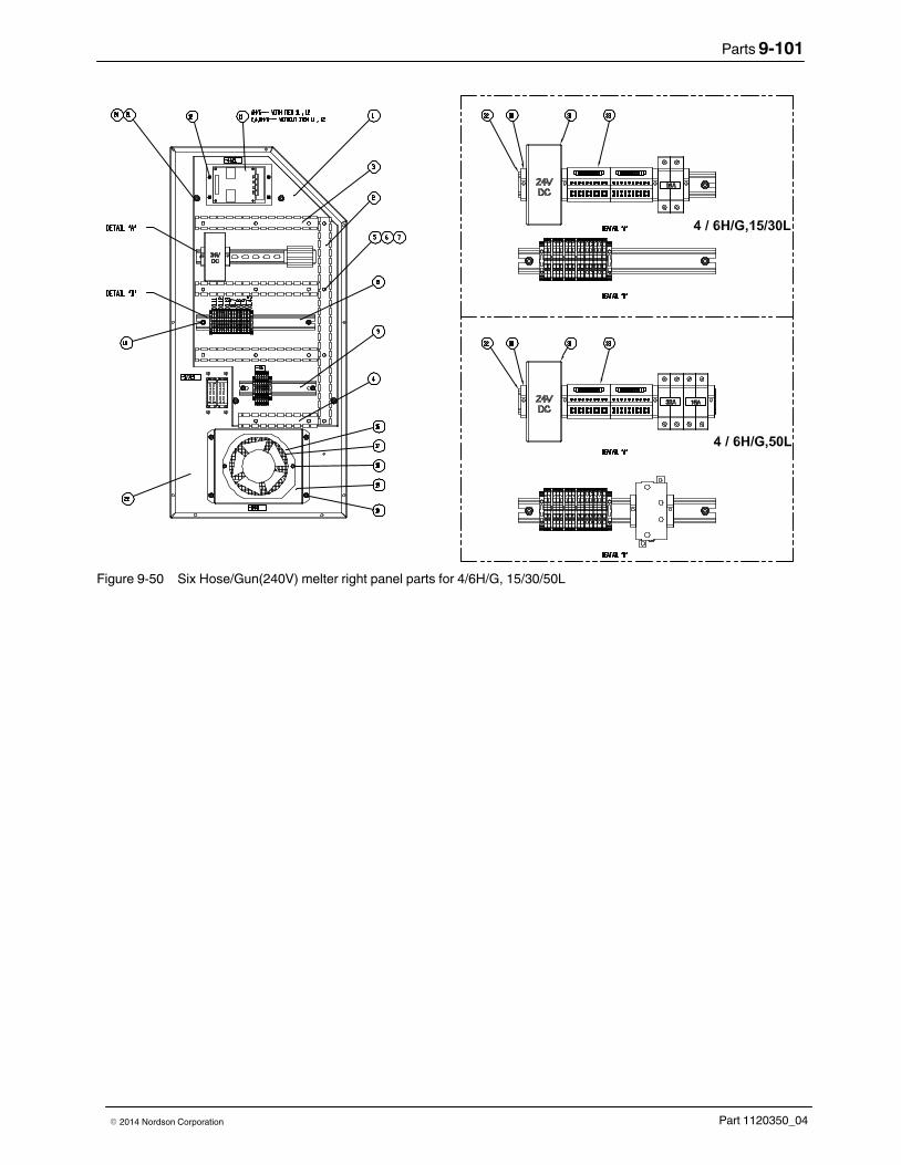
Parts 9-101
Part 1120350_04� 2014 Nordson Corporation
Figure 9-50 Six Hose/Gun(240V) melter right panel parts for 4/6H/G, 15/30/50L

Parts9-102
Part 1120350_04 � 2014 Nordson Corporation
Six Hose/Gun (240V) Melter Right Panel Parts (contd)
Figure 9-51 Six Hose/Gun(240V) melter right panel parts 4/6H/G, 100L

Parts 9-103
Part 1120350_04� 2014 Nordson Corporation
This page intentionally left blank.

Parts9-104
Part 1120350_04 � 2014 Nordson Corporation
Eight Hose/Gun (240V) Melter Right Panel Parts
See Figure 9‐45.
Item Part Description Quantity Note Panel assy, RH, 8H/G, 240V delta, touch
1 � Panel, right inside, elect cab, touch 1
2 � Wireway, 25x50x490 1
3 � Wireway, 25x50x290 3
4 � Stock, wireway, 25x50, pearl 0.19
5 � Washer, flt, M, reg, M3, zinc plate 15
6 � Washer, lk, M, spt, M3, stl, zn 15
7 � Nut, acorn, M3, stl, zn 15
8 � Terminal block, RH, 400V, AT 1
9 � Terminal block, ground, AT 1
10 � Hex nut, flanged, serrated, M5 10
15 � This item number is reserved
16 7401320 � Service kit, fan, 240VAC, 170 CFM 1
17 7401321 � Service kit, filter, fan, elect. cab 1
18 � Screw, shcs M4 x 45 gd 8.8 zp 2
19 � Panel, cover, filter 1
20 � Hex nut, flanged, serrated, M6 4
21 � Spacer sleeve, AltaBlue 4
22 � Panel, right, outside, elect cab 1
23 � This item number is reserved
24 � Insert, female, 16 pin, 116, cage clamp 1
25 � Insert, female, 16 pin, 17132, cage clamp 1
26 � Connector housing, base, 32 pin, w/cover 1
27 � Scr, pan, rec, M4x16 4
28 � Washer, flt, M, narrow, M4, stl, zn 4
29 � Washer, lk, M, spt, M4, stl, zn 4
30 � End stop, terminal block 4
31 7403526 � 24VDC power supply, 150W 1
32 � Rail, din, 280lg, AltaBlue 1
33 � Board, breakout, durablue, expand, tb, 20pos 1
34 � This item number is reserved 1

Parts 9-105
Part 1120350_04� 2014 Nordson Corporation
Figure 9-52 Eight Hose/Gun (240V) melter right panel parts for 8 H/G, 4D/100L

Parts9-106
Part 1120350_04 � 2014 Nordson Corporation
One/Two‐Pump Melter Bottom Panel Parts
See Figure 9‐53.
Item Part Description Quantity Note
Panel Assembly, Bottom, 400V Y,2D, Touch
1 � Panel, Bottom, Electrical Cabinet,2D, Touch 1
2 � EMI Filter, 500VAC, 60A, 3P+N+PE 1
3 � Terminal Block, Ground, Touch 1
4 � Grommet Rubber ID32 5
5 � SCR, SKT, M8X20, ZN 4
6 � Washer, FLT, M, REG, 8, STL, ZN 4
7 � LockWasher, M8 4
8 � Hexnut, Flanged, Serrated, M5 2
9 � Mount, Saddle Tie, DIA.6 1
10 � Nut, HEX, M5, STL, ZN 1
11 � Washer, FLT, M, REG, M5, STL, ZN 1
Figure 9-53 One/two‐pump melter bottom panel assembly parts

Parts 9-107
Part 1120350_04� 2014 Nordson Corporation
Three/Four‐Pump Melter Bottom Panel Parts
See Figure 9‐54.
Item Part Description Quantity Note
Panel Assembly, Bottom, 400V Y,4D, Touch
1 � Panel, Bottom, Electrical Cabinet, 4D/100L,Touch
1
2 � EMI Filter,500VAC,60A,3P+N+PE 1
3 � Terminal Block, Ground, Touch 1
4 � Mount, Saddle Tie, DIA.6 2
5 � Grommet Rubber ID32 8
6 � SCR, SKT, M8X20, ZN 4
7 � Washer, FLT, M, REG, 8, STL, ZN 4
8 � LockWasher, M8 4
9 � Hexnut, Flanged, Serrated, M5 2
10 � Nut, HEX, M5, STL, ZN 2
11 � Washer, FLT, M, REG, M5, STL, ZN 2
Figure 9-54 Three/four‐pump and 100L melter bottom panel assembly parts (400V melter shown)

Parts9-108
Part 1120350_04 � 2014 Nordson Corporation
Control Panel Assembly See Figure 9‐55.
Item Part Description Quantity Note
Control Assembly, ELEC, 1/2D, Touch
0001 � Panel, Assembly, Control, 2D, Touch 1
0002 1108174 � Tag, Display, ALTABLUE Touch 1
0003 7403311 � Service Kit, LCD MODULE 1
0004 7403315 � Service Kit,PCA Motor Control, Touch 1
0005 � THRDSPCRMM, Male/Female ss, hex, M3,8MMLG
6
0006 � Washer, LK, M, INT,M3, STL, ZN 6
0007 � Clamp, Ribbon Cable 1
0008 � SCR, PAN, REC, M3X8, ZN 2
0009 � Hexnut, Flanged, Serrated, M5 4
0010 � Harness, COMM, CPUMotor Control, 6", Touch 1
0011 � Mount, Saddle Tie, DIA.6 4
0012 � Nut, HEX, M5, STL, ZN 4
0013 � Washer, FLT, M, REG, M5, STL, ZN 4
Figure 9-55 Control panel assembly parts (twopump melter shown)

Parts 9-109
Part 1120350_04� 2014 Nordson Corporation
This page intentionally left blank.

Parts9-110
Part 1120350_04 � 2014 Nordson Corporation
Sensor Assembly See Figure 9‐56. The sensors on your melter may be one of two types:120‐ohm nickel or 100‐ohm platinum.
Item Part Description Quantity Note
Module, Sensor, NI, 2H/G, 400V,100L, Touch
0801 7403503 Hose Connect Assembly,NI,2H/G,2D, Touch 1
7403504 Hose Connect Assembly,NI,4H/G,2D, Touch 1
7403505 Hose Connect Assembly,NI,6H/G,2D, Touch 1
7403506 Hose Connect Assembly,NI,2H/G,100L, Touch 1
7403507 Hose Connect Assembly,NI,4H/G,4D/100L, Touch 1
7403508 Hose Connect Assembly,NI,6H/G,4D/100L, Touch 1
7403509 Hose Connect Assembly,NI,8H/G,4D/100L, Touch 1
7403510 Hose Connect Assembly,PT,2H/G,2D, Touch 1
7403511 Hose Connect Assembly,PT,4H/G,2D, Touch 1
7403512 Hose Connect Assembly,PT,6H/G,2D, Touch 1
7403513 Hose Connect Assembly,PT,2H/G,100L, Touch 1
7403514 Hose Connect Assembly,PT,4H/G,4D/100L, Touch 1
7403515 Hose Connect Assembly,PT,6H/G,4D/100L, Touch 1
7403516 Hose Connect Assembly,PT,8H/G,4D/100L, Touch 1
0802 7401367 RTD,Assembly,NI120, Grid, ALTABLUE 1
7400280 RTD Assembly, PT100, Grid, ALTABLUE 1
0803 7401368 RTD, Assembly, NI120, Reservoir, ALTABLUE 1
7400281 RTD Assembly, PT100, Reservoir, ALTABLUE 1
0804 Washer, FLT, M, REG, M6, STL, ZN 8
0805 Washer, LK, M, SPT, M6, STL, ZN 8
0806 Nut, HEX, M6, STL, ZN 8
0807 Panel Cover Manifold 4D 2
0808 Washer, FLT, M, REG, M3, Zinc Plate 8
0809 Washer, LK, M, SPT,M3, STL, ZN 8
0810 SCR, PAN, SLT,M3X6, ZN 8
0811 7403496 Harness,INL1/2,28 H/G,4D/100L, Touch 1
0812 7403501 Harness,INH3/4,400V,4D/100L, Touch 1
0813 7403498 Harness,INL5/6,8 H/G,4D/100L, Touch 1
0814 7403499 Harness,INH7/8,8 H/G,400V,4D/100L, Touch 1
0815 171856 Shunt,.1IN,2POS 2
0802 7401368 RTD, Assembly, NI120, Reservoir, ALTABLUE 1
7400281 RTD Assembly, PT100, Reservoir, ALTABLUE 1
0803 333304 SENSOR,TEMP,RTD,NI,18FT LEAD 1
162506 SENSOR,RTD,100 OHM,PLT,18FTLG 1

Parts 9-111
Part 1120350_04� 2014 Nordson Corporation
Figure 9-56 Sensor assembly parts (four‐pump 100‐ohm platinum melter shown)

Parts9-112
Part 1120350_04 � 2014 Nordson Corporation
Low Level Assembly See Figure 9‐57.
Item Part Description Quantity Note
— 1079477 Low level indication, 15/30L, one/two pump —
— 1079478 Low level indication, 50L, one/two pump —
— 1079476 Low level indication, 30/50L, three/four pump —
— 1079973 Low level indication, 100L —
1201 ‐ ‐ ‐ ‐ ‐ ‐ ‐ � Wire harness, low level 1
1202 ‐ ‐ ‐ ‐ ‐ ‐ ‐ � Low level assembly, 169 mm 1
NS ‐ ‐ ‐ ‐ ‐ ‐ ‐ � Cable tie, 4 in., 302 degrees F 5
NS: Not Shown
12021201
GASCKETROUTE WIRE FROM SWITCHASSEMBLY BETWEEN THEHOPPER GASKET AND TOP COVER.
Figure 9-57 Low level assembly parts

Parts 9-113
Part 1120350_04� 2014 Nordson Corporation
Optional Accessories To optimize the use of your system, Nordson Corporation recommends theseoptional accessories.
Pressure Indication
Part Description Note
1030537 Kit, gauge, analog pressure, 1500 psi
Pneumatic Pressure Control Valve
Part Description Note
1079939 Kit, pressure control valve, pneumatic
NOTE: Refer to Pneumatic Pressure Control Valve Parts earlier in this section for a parts list andillustration.

Parts9-114
Part 1120350_04 � 2014 Nordson Corporation
Line‐Speed Signal Generator
To use the gear‐to‐line capability of the melter, you must install a device thatmeasures the speed of the production line. The default type of line‐speedsignal input is 0-10 VDC, although other inputs can be accepted. NordsonCorporation offers the following 0-10 VDC generator.
Part Description Note
119560 Generator, 0-10 VDC, with bracket and cable
Optional Fittings
See Figure 9‐58. These fittings can be used at the melter end of a hose.
Hose SizeFitting
Part�NumberFitting Type
Fitting Size,Melter Side
Fitting Size,Hose�Side
8‐mm
7400333 Straight M16 x 1.5 9/16‐18 JIC
7400337 45‐degree M16 x 1.5 9/16‐18 JIC
7400335 90‐degree M16 x 1.5 9/16‐18 JIC
12‐mm
7401279 Straight M16 x 1.5 3/4‐16 JIC
7401278 45‐degree M16 x 1.5 3/4‐16 JIC
7401277 90‐degree M16 x 1.5 3/4‐16 JIC
16‐mm (see Note)
7400334 Straight M22 x 1.5 11/16 JIC
7400338 45‐degree M22 x 1.5 11/16 JIC
7400336 90‐degree M22 x 1.5 11/16 JIC
12
3
Figure 9-58 Typical non‐swivel fittings
1. Straight fitting 2. 45� fitting 3. 90� fitting

Parts 9-115
Part 1120350_04� 2014 Nordson Corporation
Recommended Spare Parts
Table 9-4 Recommended Spare Parts
P/N Description
All Melters
7402299 Coupling, M24, DAN/Normal (except for melters with pump SN1710)
7402293 Coupling, M24, DAN/SN1710 (melters with pump SN1710 only)
7400298 Service Kit, Heater, 240V, 800W, 1/2 X 11.65 (one/two pump melter 30/50L hopper)
7400876 Service Kit, Heater, 240V, 500W, 1/2 X6.38 (one/two pump melter 15L hoppers andthree/four pump melter 30L hoppers)
7400875 Service Kit, Heater, 240V, 750W, 1/2 x11.85 (three/four pump melter 50L hoppers)
7401316 Service Kit Heater, 240V, 1000W, 1/2X22.75 (100L melter hoppers)
7400297 Service Kit, Heater, 240V, 800W, 1/2 X 13.75 (all melter manifolds)
7400569 Service Kit, Heater, 240V, 400W, 1/2 X 13.75 (one/two pump melter reservoirs)
7400874 Service Kit, Heater, 240V, 800W, 1/2 X 27.5 (three/four pump melter and 100L melterreservoirs)
7401366 Thermoswitch Assembly, ALTABLUE
7403137 KIT,FLOW/PRESSURE CONTROL BOARD
7403138 KIT,FLOW/PRESSURE CONTROL BOARD
777404 REALY,DC24V,MY2NJ
777630 BASE, RELAY (OMRON)
7401321 Service Kit, Filter, Fan, Electrical Cabinet
7401320 Service Kit, Fan, 240VAC, 170 CFM
7400318 Service Kit, Motor Control, ALTABLUE
7140101 Interference Filter 230VAC/2X6A B
1078624 Service Kit, DURABLUE, Main, PCA
1031201 Service Kit, DURABLUE, Expansion PCA
1031175 Service Kit, DURABLUE, 2H TO 4H Conversion
207396 Solid State Relay, 100-260VAC, 15A, DC Trigger
7400070 Solid State Relay, 100-260VAC, 35A, DC Trigger
207932 Safety valve, 85 bar, VB/DB
7400299 Service Kit, O-ring, Viton, 45 X 2
7400300 Service Kit, O-ring, Viton, 26 X 2
1058990 CordStock, 3 MM OD, Viton, 75D
7400134 Gasket, Hopper, 15L (one/two pump melters)
7400135 Gasket, Hopper, 30/50L, ALTA
7400326 Gasket, 50L, Hopper, 4D
7400327 Gasket, 30L, Hopper, 4D
7402295 Service Kit, Motor, BG06‐31/D06LA4TOF
7403311 Service kit, LCD module
Continued...
1107260 BATTERY,COIN CELL,3.0V,24MM,LITHIUM

Parts9-116
Part 1120350_04 � 2014 Nordson Corporation
7403314 Service kit, solenoid valve, 2/3, 1 unit
7403315 Service kit, PCA motor control, touch

Parts 9-117
Part 1120350_04� 2014 Nordson Corporation
Recommended Spare Parts (contd)
P/N Description
All Melters
7403317 Kit, LCD cover
7403318 Service kit, pressure regulator, ARM10
7403274 Service kit, insulation, hopper, 15L, 2D
7403275 Service kit, insulation, hopper, 30L, 2D
7403276 Service kit, insulation, hopper, 50L, 2D
7403277 Service kit, insulation, hopper, 30L, 4D
7403278 Service kit, insulation, hopper, 50L, 4D
7403279 Service kit, insulation, hopper, 100L
7403280 Service kit, insulation, reservoir, 100L
7403281 Service kit, insulation, hopper, 15L, W/R, 2D
7403282 Service kit, insulation, hopper, 30L, W/R, 2D
7403283 Service kit, insulation, hopper, 50L, W/R, 2D
7403284 Service kit, insulation, hopper, 30L, W/R, 4D
7403285 Service kit, insulation, hopper, 50L, W/R, 4D
7403286 Service kit, insulation, hopper, 100L, W/R
7402919 Service kit, lid, AB2D15L/4D30L
7402920 Service kit, lid, AB2D30&50L/4D50L
7402921 Service kit, lid, AB100L
7402922 Service kit, hinge, lid, AltaBlue
7402923 Service kit, hinge, support, lid, AB100L
7403095 Kit, change normal pump to SN1710
7403096 Kit, change SN1710 to notmal pump
7403139 Kit, transducer, applicator, 4-20mA
7403140 Kit, transducer, applicator, 0-10 VDC
7403141 Kit, cable, 0-10V, 16 ft, pressure
7403142 Kit, cable, 0-10V, 24 ft, pressure
7403143 Kit, cable, 0-10V, 30 ft, pressure
7403146 Kit, Truflow, T-style, 12mm, Trueflow, melter
7403147 Kit, Truflow, M-style, 12mm, Trueflow, melter
7403148 Kit, cable, Truflow, L-16 ft w/ 6 pin conn
7403149 Kit, cable, Truflow, L-24 ft w/ 6 pin conn
7403150 Kit, cable, Truflow, L-30 ft w/ 6 pin conn
7403151 Kit, RVS 1 melter, 24 ft, touch
7403152 Kit, RVS 1-5 melter, 50 ft, touch
Continued...

Parts9-118
Part 1120350_04 � 2014 Nordson Corporation
P/N Description
All Melters
7403153 Kit, RVS 1-5 melter, 100 ft, touch
7403154 Kit, cable, 4-20 mA, 16 ft, pressure
7403155 Kit, cable, 4-20 mA, 24 ft, pressure
7403156 Kit, cable, 4-20 mA, 30 ft, pressure

Parts 9-119
Part 1120350_04� 2014 Nordson Corporation
Table 9-5 Recommended Pump Spare Parts
P/N Description
Pumps
394589 Service Kit, PUMP O-ring, Single-Stream, PUMP SIZE SN0030-SN0773
394596 Service Kit, PUMP O-ring, Single-Stream, PUMP SIZE SN1710
7104645 Service Kit, PUMP O-ring, DUAL‐STREAM
Select Based on Specific Melter Configuration
One/Two‐Pump Melters, 240 VAC
7403435 MAIN CONTACTER DILM50C
318248 circuit breaker, 63 A, 3‐pole
7400320 Circuit breaker, 32 A, 2‐pole
7400321 Circuit breaker, 13 A, 2‐pole
7400322 Circuit breaker, 16 A, 2‐pole
7400323 Circuit breaker, 2 A, 2‐pole
256141 Circuit breaker, 16 A, 3‐pole, inductive load
One/Two‐Pump Melters, 400 and 480 VAC
7403435 MAIN CONTACTOR, DILM50C
318248 circuit breaker, 63 A, 3‐pole
7400071 Circuit breaker, 32 A, 1‐pole
7400072 Circuit breaker, 13 A, 1‐pole
251364 Circuit breaker, 16 A, 1‐pole, inductive load
256227 Circuit breaker, 2 A, 1-pole
256141 Circuit breaker, 16 A, 3‐pole inductive load
Continued...

Parts9-120
Part 1120350_04 � 2014 Nordson Corporation
Recommended Spare Parts (contd)
Three/Four‐Pump and 100L Melters, 240 VAC
7403071 Main Contactor, DILM80C
7104855 Circuit breaker, 90 A, 3‐pole, UL489
7400320 Circuit breaker, 32 A, 2‐pole
7400321 Circuit breaker, 13 A, 2‐pole
7400322 Circuit breaker, 16 A, 2‐pole
7400323 Circuit breaker, 2 A, 2‐pole
256141 Circuit breaker, 16 A, 3‐pole, inductive load
Three/Four‐Pump and 100L Melters, 400 and 480 VAC
7403435 Main Contactor, DILM50C
318248 circuit breaker, 63 A, 3‐pole
7400071 Circuit breaker, 32 A, 1‐pole
7400072 Circuit breaker, 13 A, 1‐pole
251364 Circuit breaker, 16 A, 1‐pole, inductive load
256227 Circuit breaker, 2 A, 1-pole
256141 Circuit breaker, 16 A, 3‐pole, inductive load
Pt100 Melters
7400281 RTD assembly, reservoir, PT100
7400280 RTD assembly, tank, PT100
Ni120 Melters
7401367 RTD assembly, reservoir, Ni120
7401368 RTD assembly, tank, Ni120

Technical Data 10-1
Part 1120350_04� 2014 Nordson Corporation
Section 10
Technical Data
General Data Storage temperature - 45° C to + 75 ° C
- 49 ° F to + 167 ° F
Type of heating Cartridge‐type resistance heating elements
Temperature sensor Ni120 and PT100 � 1 ° C
— Measuring precisionMaterial pressure 5 to 85 bar 0.5 to 8.5 MPa 72.5 to 1�233 psi
Melting capacity 1 tank‐full per hour
Degree of protection IP 33
Noise emission <70 dB
Motor type 3 ph AC motor
Gear box type Helical gear
Motor/pump speeds 94 rpm
Heatup time <45 min
Temperatures Min. ambient temperature - 5 °C 23 °F
Max. ambient temperature 40 ° C 104 °F
Humidity 10 to 95 %, not condensing
Min. operating temperature(setpoint)
40 ° C 100 °F
Max. operatingtemperatures
230 ° C 450 °F
Overtemperature shutdownby thermostat
260 ° C 500 °F

Technical Data10-2
Part 1120350_04 � 2014 Nordson Corporation
Electrical Data
WARNING! The unit is designed for only one operating voltage. Operateonly at the operating voltage shown on the ID plate.
Available operatingvoltages
230 VAC 3-phase without neutral (Delta)
400 VAC 3-phase with neutral (star — WYE)
400 VAC 3-phase without neutral (Delta)
480 VAC 3-phase without neutral (Delta)
Maximum melterpower requirements
400 VAC Delta480 VAC Delta400 VAC Star WYE
One/two-pump melter Two hose/applicator 15L:8380W30L:9482W50L:12420W
Four hose/applicator 15L:12053W30L:13155W50L:16094W
Six hose/applicator 15L:13890W30L:14992W50L:17931W
Two-pump melter Eight hose/applicator 30L:23166W50L:25232W
Three/four-pump melter
Four hose/applicator 30L:18684W50L:20750W
Six hose/applicator 30L:20521W50L:22587W
Eight hose/applicator 30L:24194W50L:26161W
100L Two hose/applicator 100L:21347WFour hose/applicator 100L:25021WSix hose/applicator 100L:26858WEight hose/applicator 100L:30531W

Technical Data 10-3
Part 1120350_04� 2014 Nordson Corporation
Maximum melterpower requirements
230 VAC Delta
One/two-pump melter Two hose/applicator 15L:9124W
30L:10324W50L:13524W
Four hose/applicator 15L:13124W30L:14324W50L:17524W
Six hose/applicator 15L:15124W
30L:16324W50L:19524W
Two-pump melter Eight hose/applicator 30L:25224W50L:27474W
Three/four-pump melter
Four hose/applicator 30L:20344W50L:22594W
Six hose/applicator 30L:22344W
50L:24594WEight hose/applicator 30L:26344W
50L:28594W100L Two hose/applicator 100L:23244W
Four hose/applicator 100L:27244WSix hose/applicator 100L:29244WEight hose/applicator 100L:33244W
Max. load per hosereceptacle (2 chan-nels), two/four/six/eight hose/applicatormelters
1000 W, any single hose or applicator
1200 W, any hose/applicator pair2000 W, sum of hose/applicator pairs 1 and 22000 W, sum of hose/applicator pairs 5 and 62000 W, any single hose, or applicator 3 or 42000 W, any single hose, or applicator 7 or 82000 W, hose/applicator pair 3 or 42000 W, hose/applicator pair 7 or 84000 W, sum of hose/applicator pairs 3 and 44000 W, sum of hose/applicator pairs 7 and 8NOTE: Total external wattage must not exceed 12,000 W.

Technical Data10-4
Part 1120350_04 � 2014 Nordson Corporation
Mechanical Data
One/Two and Three/Four Pump Melters
Item 15L 30L 50L 100L Note
Weight 200 kg (441 lb) One/two pump:225�kg (496 lb)
Three/fourpump:440 kg (970 lb)
One/two pump:250 kg (551 lb)
Three/fourpump:472 kg (1,041 lb)
590 kg (1,301 lb)
Tank opening(length and width)
145 x 270 mm 270 x 270 mm 270 x 270 mm 270 x 635 mm
Approximate tankvolume
15 L 30 L 50 L 100 L
Number of pumps(one/two‐pumpmelter)
1-2single‐stream
1-2 dual‐stream
1-2single‐stream
1-2 dual‐stream
1-2single‐stream
1-2 dual‐streamNot applicable
Number of pumps(one/two‐pumpmelter)
Not applicable 2 single‐stream
2 dual‐stream
2 single‐stream
2 dual‐stream
Not applicable A
Number of pumps(three/four‐pumpmelter)
3-4single‐stream ordual-streampumps
3-4single‐stream ordual-streampumps
Up to foursingle-stream ordual-streampumps
Number of hoseconnections
One single‐stream manifold: 7 connections
Two single‐stream manifolds: 3 connections per pump stream
Dual‐stream manifold: 2 connections per pump stream
NOTE A: Only for 2 pumps with 8 hose/applicator.

Technical Data 10-5
Part 1120350_04� 2014 Nordson Corporation
Electrical Schematics Refer to the electrical schematics provided with the melter.

Technical Data10-6
Part 1120350_04 � 2014 Nordson Corporation
Hydraulic Schematic
ÉÉÉÉÉÉ
HOPPER
GRID
ADHESIVETCS
GEAR
MOTORCONTROL
FILTER
PUMP
CV
PRV
ÉÉÉÉÉÉ
GEAR
FILTER
PUMP
CV
PRV
MOTORCONTROL
DRAIN VALVE
DRAIN VALVE
MOTOR MOTOR
Figure 10-1 Hydraulic system schematic

Calculating Melter Power Requirements (Including Heater Specifications) A-1
Part 1120350_04� 2014 Nordson Corporation
Appendix A
Calculating Melter Power Requirements(Including Heater Specifications)
Before locating the melter on the production floor or attaching hoses andguns to the melter, you must calculate the electrical power required by thehoses and guns and confirm that the required power does not exceedmaximum allowable wattages. Properly calculating melter powerrequirements will prevent damage to the melter and identify the maximumallowable distance between the melter and the point at which the hot melt isdispensed.
The following three maximum wattages must be considered when calculatingmelter power requirements.
� Single‐component maximum—The wattage of any single hose or
gun
� Hose/gun pair maximum—The combined wattage of any hose and
gun (hose/gun pair)
� Two hose/gun pair maximum—The combined wattage of hose/gun
pairs 1 and 2 or hose/guns pairs 3 and 4
If your Nordson representative has already calculated the hose/gun powerrequirements and confirmed that the maximum allowable wattages will not beexceeded, then no further calculation is necessary. However, you shouldre‐evaluate the hose and gun power requirements before you:
� add a new hose or gun to the melter that was not factored into the
original wattage evaluation
� replace an existing hose with a longer hose or an existing gun with a
larger gun

Calculating Melter Power Requirements (Including Heater Specifications)A-2
Part 1120350_04 � 2014 Nordson Corporation
Table A-1 Maximum Allowable Hose/Gun Wattages(Eight Hose/Gun Melters)
Component Maximum Wattage
Any single hose or gun 1000W
Any hose/gun pair 1200W
Sum of hose/gun pairs 1 and 2 2000W
Sum of hose/gun pairs 5 and 6 2000W
Any single hose, or gun 3 or 4 2000W
Any single hose, or gun 7 or 8
Hose/gun pair 3 or 4 2000W
Hose/gun pair 7 or 8
Sum of hose/gun pairs 3 and 4 4000W
Sum of hose/gun pairs 7 and 8
NOTE: Total external wattage must not exceed 12,000 W.

Calculating Melter Power Requirements (Including Heater Specifications) A-3
Part 1120350_04� 2014 Nordson Corporation
Table A-2 Power Calculations (400V WYE)
SIZE H/G PUMP MOTOR POWER STAMPING
15L 2 H/G 2D 2 motor 8380 3Ø N/PE AC 400/230 V 50/60 Hz 22A
1 motor 7865 3Ø N/PE AC 400/230 V 50/60 Hz 20A
30L 2 motor 9482 3Ø N/PE AC 400/230 V 50/60 Hz 27A
1 motor 8967 3Ø N/PE AC 400/230 V 50/60 Hz 24A
50L 2 motor 12420 3Ø N/PE AC 400/230 V 50/60 Hz 27A
1 motor 11906 3Ø N/PE AC 400/230 V 50/60 Hz 24A
100L 100L 4 motor 21347 3Ø N/PE AC 400/230 V 50/60 Hz 35A
3 motor 21347 3Ø N/PE AC 400/230 V 50/60 Hz 33A
2 motor 20319 3Ø N/PE AC 400/230 V 50/60 Hz 31A
1 motor 19804 3Ø N/PE AC 400/230 V 50/60 Hz 31A
15L 4 H/G 2D 2 motor 12053 3Ø N/PE AC 400/230 V 50/60 Hz 22A
1 motor 11539 3Ø N/PE AC 400/230 V 50/60 Hz 20A
30L 2 motor 13155 3Ø N/PE AC 400/230 V 50/60 Hz 27A
1 motor 12641 3Ø N/PE AC 400/230 V 50/60 Hz 24A
50L 2 motor 16094 3Ø N/PE AC 400/230 V 50/60 Hz 27A
1 motor 15580 3Ø N/PE AC 400/230 V 50/60 Hz 27A
30L 4D 4 motor 18684 3Ø N/PE AC 400/230 V 50/60 Hz 33A
3 motor 18170 3Ø N/PE AC 400/230 V 50/60 Hz 31A
50L 4 motor 20750 3Ø N/PE AC 400/230 V 50/60 Hz 38A
3 motor 20236 3Ø N/PE AC 400/230 V 50/60 Hz 36A
100L 100L 4 motor 25021 3Ø N/PE AC 400/230 V 50/60 Hz 43A
3 motor 25021 3Ø N/PE AC 400/230 V 50/60 Hz 41A
2 motor 23992 3Ø N/PE AC 400/230 V 50/60 Hz 39A
1 motor 23478 3Ø N/PE AC 400/230 V 50/60 Hz 39A
15L 6 H/G 2D 2 motor 13890 3Ø N/PE AC 400/230 V 50/60 Hz 26A
1 motor 13376 3Ø N/PE AC 400/230 V 50/60 Hz 26A
30L 2 motor 14992 3Ø N/PE AC 400/230 V 50/60 Hz 27A
1 motor 14478 3Ø N/PE AC 400/230 V 50/60 Hz 26A
50L 2 motor 17931 3Ø N/PE AC 400/230 V 50/60 Hz 27A
1 motor 17417 3Ø N/PE AC 400/230 V 50/60 Hz 27A
30L 4D 4 motor 20521 3Ø N/PE AC 400/230 V 50/60 Hz 36A
3 motor 20006 3Ø N/PE AC 400/230 V 50/60 Hz 36A
50L 4 motor 22587 3Ø N/PE AC 400/230 V 50/60 Hz 38A
3 motor 22073 3Ø N/PE AC 400/230 V 50/60 Hz 36A
100L 100L 4 motor 26858 3Ø N/PE AC 400/230 V 50/60 Hz 45A
3 motor 26858 3Ø N/PE AC 400/230 V 50/60 Hz 45A
2 motor 25829 3Ø N/PE AC 400/230 V 50/60 Hz 45A
1 motor 25315 3Ø N/PE AC 400/230 V 50/60 Hz 45A

Calculating Melter Power Requirements (Including Heater Specifications)A-4
Part 1120350_04 � 2014 Nordson Corporation
Table A-3 Power Calculations (400V WYE) contd.
SIZE H/G PUMP MOTOR POWER STAMPING
30L 8 H/G 2D 2 motor 23166 3Ø N/PE AC 400/230 V 50/60 Hz 38A
50L 2 motor 25232 3Ø N/PE AC 400/230 V 50/60 Hz 42A
30L 4D 4 motor 24194 3Ø N/PE AC 400/230 V 50/60 Hz 38A
3 motor 23680 3Ø N/PE AC 400/230 V 50/60 Hz 38A
50L 4 motor 26261 3Ø N/PE AC 400/230 V 50/60 Hz 42A
3 motor 25747 3Ø N/PE AC 400/230 V 50/60 Hz 42A
100L 100L 4 motor 30531 3Ø N/PE AC 400/230 V 50/60 Hz 46A
3 motor 30531 3Ø N/PE AC 400/230 V 50/60 Hz 46A
2 motor 29503 3Ø N/PE AC 400/230 V 50/60 Hz 46A
1 motor 28988 3Ø N/PE AC 400/230 V 50/60 Hz 45A

Calculating Melter Power Requirements (Including Heater Specifications) A-5
Part 1120350_04� 2014 Nordson Corporation
Table A-4 Heater Specifications
2 Pump Platform P/N Description QTY. RESISTANCE/EACH(OHMS)
MIN. MAX.
15L Hopper 7402319 HEATER, 240V 500W,.50DIA X 6.38LG
4 98 115
Reservoir 7400481 HEATER CARTRIDGE, 240V400W, .50DIA X 13.75LG
3 123 144
Manifold 7400051 HEATER CARTRIDGE, 240V800W, .50DIA X 13.75 LG
3 61 72
30L Hopper 7402317 HEATER, 240V 800W,.50DIA X 11.65LG
4 61 72
Reservoir 7400481 HEATER CARTRIDGE, 240V400W, .50DIA X 13.75LG
3 123 144
Manifold 7400051 HEATER CARTRIDGE, 240V800W, .50DIA X 13.75 LG
3 61 72
50L Hopper 7402317 HEATER, 240V 800W,.50DIA X 11.65LG
8 61 72
Reservoir 7400481 HEATER CARTRIDGE, 240V400W, .50DIA X 13.75LG
3 123 144
Manifold 7400051 HEATER CARTRIDGE, 240V800W, .50DIA X 13.75 LG
3 61 72
4 Pump Platform
30L Hopper 7402319 HEATER, 240V 500W,.50DIA X 6.38LG
9 98 115
Reservoir 7400480 HEATER CARTIDGE, 240V800W, .50DIA X 27.5LG
3 61 72
Manifold 7400051 HEATER CARTRIDGE, 240V800W, .50DIA X 13.75 LG
6 61 72
50L Hopper 7402318 HEATER, 240V 750W, .50DIA X 11.85LG
9 65 77
Reservoir 7400480 HEATER CARTIDGE, 240V800W, .50DIA X 27.5LG
3 61 72
Manifold 7400051 HEATER CARTRIDGE, 240V800W, .50DIA X 13.75 LG
6 61 72
100L Hopper 7400910 HEATER, 240V 1000W,.50DIA X 22.75LG
9 49.25 57.45
Reservoir 7400480 HEATER CARTIDGE, 240V800W, .50DIA X 27.5LG
6 61 72
Manifold 7400051 HEATER CARTRIDGE, 240V800W, .50DIA X 13.75 LG
6 61 72

Calculating Melter Power Requirements (Including Heater Specifications)A-6
Part 1120350_04 � 2014 Nordson Corporation

Technical File Contact:
Dieter Ziesmer
Nordson Engineering GmbH
Lilienthalstrasse 6
21337 Lueneburg
GERMANYDate: 20 March 2014
Gregory P. Merk, Senior Vice PresidentAdhesives Dispensing Systems
1105311A05
DOC074R6
Nordson Corporation � 28601 Clemens Road ��Westlake, Ohio
EC Declaration of Conformity
for Adhesive and Sealant Application Equipment conforming to European Council Directives
PRODUCTS:
AltaBlue� Melters, Models 15, 30, 50, 100
AltaBlue� TT Melters, Models A4, A10, A16
AltaPail� Melters
Cobalt� GR Series Bulk Material Unloaders
DuraBlue��Melters
FoamMelt� FM‐200 Melter
Freedom� Hot Melt Adhesive System
Fulfill� Retrofit Kit
Mesa� Melters
MiniPUR� Melters
ProBlue� Melters, Models P4, P7, P10, P15, P30 and P50
ProBlue� Fulfill�, Models P4F, P7F, P10F
PURBlue� Melters
Series 3000V Melters
SureFoam� Foam Dispensing System
APPLICABLE DIRECTIVES:
Machinery Directive: 2006/42/EC
Electromagnetic Compatibility Directive: 2004/108/EC
STANDARDS USED TO VERIFY COMPLIANCE:
EN ISO 12100 EN 60204‐1 EN 61000-6-4
EN ISO 13732‐1 EN 61000‐6‐2
EN 55011 (Class A, Group 1 for industrial environments. Use in
other environments may pose potential difficulty ensuring
electromagnetic compatibility due to conducted as well as
radiated disturbances.)
PRINCIPLES:
This product has been manufactured according to good engineering practice.
The product specified conforms to the directives and standards described above.
Model Number_________________________
Serial Number______________________________________