alternators - bristoloda.orgbristoloda.org/newboda/wp-content/uploads/.../02/lucas-alternators.pdfin...
TRANSCRIPT
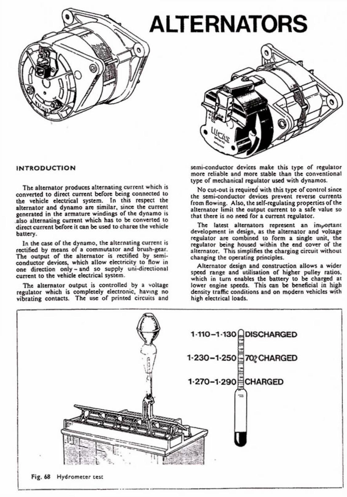
ALTERNATORS
INTRODUCTION
The alternator produteS Ilttrnaling CIIffent which is converted to direct current bcfo~ ban, f;()nnec:led \0 tbe vchicle dcctriCilI systcm. In this rcspeocl the Iltemator and dynamo are similar. sin~ th.c current acnerated in Ihe Irmlture windina' of th.e dynamo is • also alternltinS cuncnl which hu 10 be converted to d irect c:urrent before it can be ",sed to ch.ar~ th.e vehicle blottery.
In the ease or the dynamo. the altcrnllina current is redified by means of I commutator Ind brwh·snr. The output or ttie Iltemltor is rectified by semi. conduetor duica, which IlIow dcc.lricily to flow in onc dire:tion only _ Ind so supply uni-d irectionll current to the vchicle electrical system.
The ILtemltor output is controlled by I volllgc (caulllOr which is completely electronic. hlv,ng no vibrating contacts. Thc use of printed circuits and
Hydrometcr telt
JoCmi-conductor devices mike: Ihi5 type or rtlula lor more reil.blt and morc stable thin the cotIYe!llional type of mechanical !qul.tor used .... ith dynamos.
No CUI·out is required' with Ih is type of !;(lotro! since the scmi-conductor dcv;CC$ prevcnt reverse currcnU from lIowing. Abo, the self·regulating propeniu orllle ,Item.tor limit the Olllput current 10 I safe valut so Ih.t thert is no nted for I C'Ulnnt regulator .
The Iltest alternators represent In im.,orunl dcYclopmcnl in daiS", as Ihe altuTator and voltaic rcg..uator are combined 10 form I single uni t. the rqulllor bejn, housed within the end co<'er of the alternator. Thi, simpli!ks the chlrliDI tireui! without changina the opera!ins prinapics.
Allcftl.ia!or desi," and construction alLows. wider speed range al'ld uUliH-tion of hilher !JUne,. rauO$. which in turn enables the bancry 10 be chaflO:d I1 lower cngine speeds. This can be beneficia l in hiah den~ty In.ffic: conditions Ind on modern vehicles with hiah cl«trical IMds.
- ------ _._------- ---,

In th is sectlon .... c shall discuss the test prox edure for two types of A.C. system : I. The baltery.neited machine \l OAC and !l AC}.
wheA' the ;alternato r field depends o n the bau t ry, VII I rela1. for its ini,i.1 c)I;citatio n. Conscqucl\lly. I.
"31 bl lluy wo uld result in no chat,e c...:n if Ihe ,"ch icl .: is 11lIned 01 10w'n&. which I, pon lbl.: w" h • Diesel enp tle'.
2. The. K'lf-cJcited machine: (the AC a nd " e R rln, e). WMIC. Ihhou,h some ncitation is pro""k d frolll the bluer)' vi. the "'lrnil'll'i,hl th is i, nOI essent •• 1 as the machine i, u pable of lupplyina: iu own St ili ein:uit whcn driven rut enou,h. The dil'retcnec betwHn In AC and AeR system is that the fonner U,\.e$ .n nlern. ' regulator whiln the AeR hts I\~ rClulalor incorporated. in the machine.
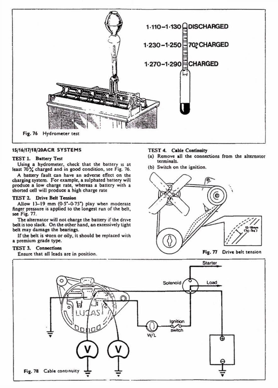
TEST \ . S'Hcry Test US,", I hydrometer , check that the ba\\el')' is ~I
lu st 70% (k",ed and in ,ood condition. KC Fig. 61. A bl1tery fa ult .:an h-.vc an 1Id"enc dl'eet o n ~ i'le
charp ng system. For Clamp]e, 11 sulpi'lalcO banc')' will produce Il low chllf'le rate while Il blue!')' .... ,Ih a shoned 1%11 will produce Il high charge rate.
TEST 2. Driye Ikll T,nsioa Allow 1)- 19 mm ((). !i "-41S' ) play when mooerate
fingcr pressu.e is applied to the Io n gal run o f belt. Sce Fi,. 69.
The ahernator will not charge Ihe balle!,), if Ihe dri ve belt i5 too slack. On the other hand. an uecnivcly t ight belt may daml,e the bearin~.
If the belt is worn o r oily, it should be replaced with a premium 'ride type. TEST 3. eon-m_
En5u.e thlt IlIlcads are in pmition.
TEST.. 0«10;,"1 6RA Rd"y The purpoK of the 6RA relay is to dc-cne r, iK tM
alternator lield wind i",- when IM engine: is S'l at ionuy. The relay i1 eonnected to Ihe i,nition lwitch so thal
it openta only when Ihe ignition i~ ~wilChed 'on '. The roto r field is compleled by contaet1 'Cl' Ind '0 '.
The alternator will not charge the batte ry If the relay contacts fa ,l lo cloS('.
o
(c .
Fi,. 69 Dn vc be ll lenllon
la) With Ihe engine Slal ionl l')', disconnect the ballcry eant. cable a"d connect a" ammeter in the alternato r main output lead 1$ shown in F ig. W.
Cb) Removt tile eablu (rom terminlls 'C l' and 'Cl ' a l tile ,c lay Ind link logeIJKr. Re-conncr::t the bAttery eanh cable, ,witch on IM igni tion a nd run the e ngine at 1,500 rev/ min.
Ic l If the ammeter now sllow$ a ChalgC, the previous (ai lure wu due 10 Ihe relay, or iu llsociatcd wiring, connections etc.
Id) Connect "ollmeler aClou 'Wl ' and 'W2'. The vo ltmeter sho uld read battery voluo&e if Ihe rclay has a good eanll I nd 5upply. I( no read ing, proceed 10 (e).
le) Chcr::1c: rellY eanh conncr::tion by conncr::ting tile vol~tC1' between 'WI ' (white lead) and a good tilnh. TM YOllmetct should read battery volta,o:.. If not, dIcr::t that the supply lead (viI ipl ition swilch) and iu eonncctioni are in good condition.
Nilte: Some ~idC$ are litted with 11 pressure iwitch in the n:Jay carth lead. Connect a temporary
I-ALTERNATOfI
Sf"'I'ITEI'I SOt.EHOID
'-_________ ,. ignitlooo _iIcIo
------------. ,. "i·'~
'--_ _ _ ____ _ . ___ _ __ _______ _ ---l

--------------------------------~
I I
I
, •
lud belwun luminal 'Wl' or. Ihe rclay and earth. If VOIIm<:lcr 110 .... rn(\s bauery voltaic. 1t1c prcs.surc ~ .... ilch IS probably (.lull),.
TEST S. Cbe<:kint: "RA Rday The 16RA relay is checked in a s;millf mlnfl~r \0
the 6RA. The "anous c/lecks arc shown in R,. -I. Conneet ammeter in the main charlin, lead hI Lhe
b.i.ltc ry (I) Remove COflnCCliOI\$ 'Cl' and 'C2' and li~ ~ 10'
gether (Fi,. 71a). Connect ,",oltmclcr bel""~n ' WI ' and eantl .
I
Run alternator .111 char,in, speed (1.500 ( ."ine lcv/min) .
,
Ammeter mould no .... show a c;hir,c and the volt. me ter 6-8V. Note: I. If the alttrnllOr stops cha.,in, .... hen
'CI' and 'C2' uc rc-conn«led \0 the relay, proaed 10 Test (b).
2. Ir Immelcr indiellC'S • (harae but \lolt. mClcr reads l Cro, proceed. 10 Tesl (eJ .
Ib) The (ollo .... ;nl CiKll il chccb must be nrried OUI before condemning the rel.y. Connect voltmeter between the rollowin, points :
RtJu/tJ (i) 'CI' and earth (Fig. lib) _ System voLtagc
(ii) 'Cl' and ·W2'I Fi,. lie) _ System volu,ge
Q
o <T.
Cheek,n, field ("C",( .... . _ _ _ . __________ _______________ J
Witlr ignition ~wilclrN on - SyStem ~ollage (i) 'R' and earth (Fis:. 7Id)
(i i) '0' and e<lrth (Fig. 7Ie) - Appro~. 2 ~olu (c) Remove 'AL' lead at alternator and connecl vo lt·
meter betwo:en 'AL' terminal and earth (Fig, 71f). Run engine ilt charging speed.
Voltmeler should read 6-8V (1 2V sy )!~ms ) or 14--ISV (24V systems). If meter shows lero reading, replace ai1c'na:ol
TEST 6. Cbedr.in\l: Field Circuit Disconnect leads from the voltage regulato r and link
together 'F' and '_. terminals, usins: an ammeter , Fig. 72. (If 16RA is used, conncctlerminals 'C l ' and '0'). With the ignition 'on' the ammeter should read approx. 3A. ;0
Note; Ifthcn: is no ruding, conne<:t a volt~t=r across alternator field Icnninah. CO$e ignition, if the voltmeter rca.ds battery voltage there is a fault in the altanator field. No reading indicates a winns: Fault belween the alternator field ter· minals ilnd the relay or regulator 'F' terminals (on positive eanh check urth lIy-lead),
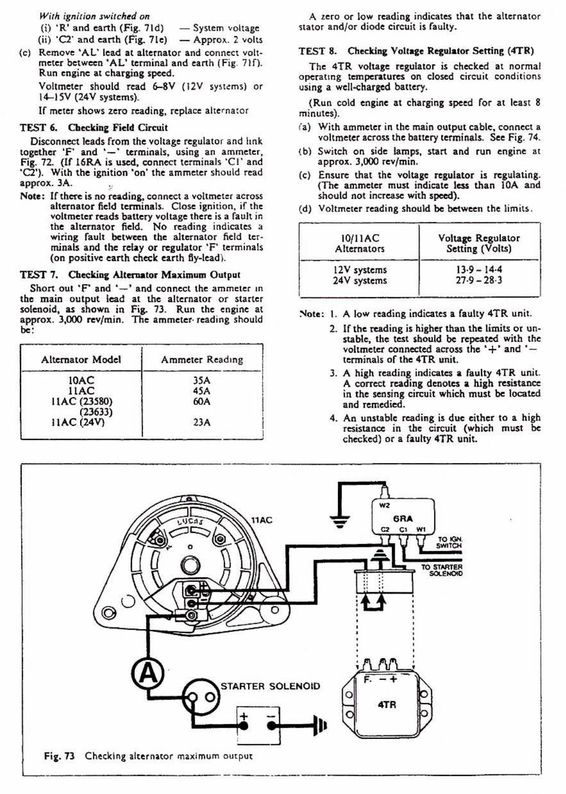
TEST 1, Cbceki", AitftUlltor Maximum Output Short out 'P aM '- ' and connect the ammeter III
the main output lead at the alternator or starter solenoid, as shown in Fig. 73. Run the engine at approx. 3,000 rev/min. The ammeter· read ing should
"'" Alternator Model Ammeter Reading
IOAC J5A ,
11AC <lA I , IIAC (23~80) r<JA I (236))) , IIAC (24V) 2lA I ,
A zero or low readin. indicates Ihat the altemalor n alOI andlor diode circuit 1$ faulty.
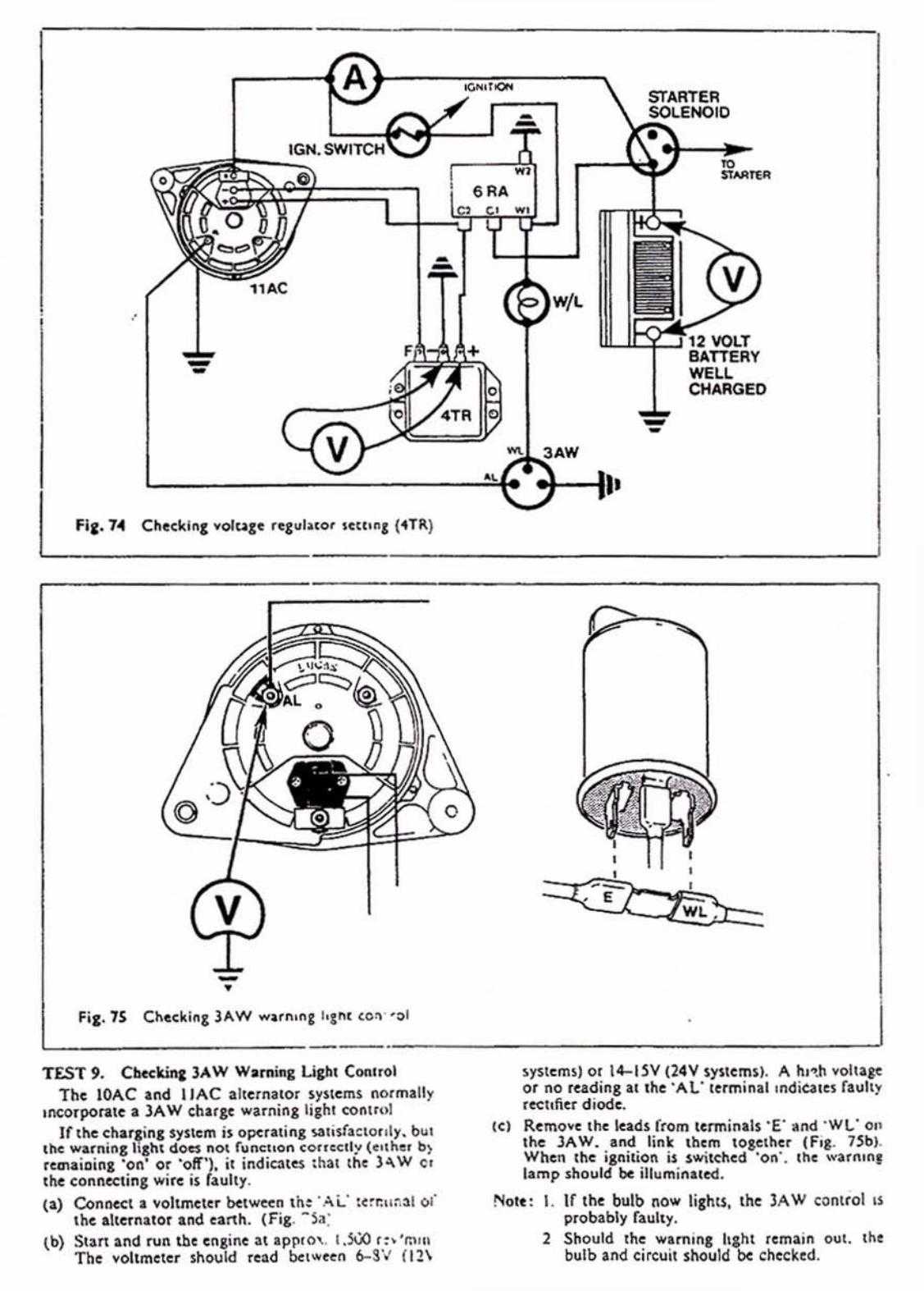
TEST S. Checld", Vallate RezulatM Settin!:, (4TR)
The 4TR voltase regulator is checked al normal operatmg temperatures on closed circuit conditio!l5 usins: a well-<:har~ battery.
(Run cold engine at charging speed for at least 8 minutes) . (a) With ammeter in the main output cable, connect l
voltmeter across the banery terminals. See Fig. 14. (b) Switch on side lamps, start and run ensine at
approll. 3,000 rev/min, (c) Ensure that the voltage regulator is regulating.
(The ammeter must indicate less than lOA and should not increase with speed).
(d) Voltmeter reading should be between the limits .
IO{lIAC Voltace Regulator Alternators Setting (VoILS)
12V systems 13-9-14·4 24V systems 27-9-28-3
:'>Iote: 1. A low reading indicates a Faulty 4TR unit .
2. IF the rudins: is higher than the limits or un· stable, the test should be repeated with the voltmeter connected across the '+' and 'terminals of tbe 4TR unit,
3. A high reading indiates a faulty 4TR unit. A COITect reading denotes a high fe$inance in the sensing circuit which must be located and remedied.
4. An unstable reading is due either 10 a high r~i$tancc in the circuit (which must be che<:ke<i) or a faulty 4TR unit.
,R'
•
,. ..... S"'R'''' SOLENOID - .TR
,
: : •
t wi.)
~----------------------------~ TEST 9. Chcc lr.in& 3A W Wami", U,tu ConHol
Tht IOAC Ind \ IAC alterna tor ~y$lemS nOlmaliy "'corporate a )AW chargc warning 1.,hl conlrol
If the char,in, system is operal; 11, Ioal i$faclorlly. b", Ihe warning lI,ht doC$ not f ... n"uon co. ,~cll )' (cuh • • b} rc."a.'O; 1I1 'on' or 'olf '),;1 indic:r.t~ :1110\ the l ... W Cl 11\( connecting wi re is faulty.
(;a) Conl\(et I voltmeter betwccn Ih: 'Ai.' :c~r:"~. 3.1 of IlIe alterna tor .nd .antl. (Fi, . -Sa:
,bl Start and nl(l the cnginc at apl'lO', I J";'O r :. 'mu, The yoltmeter should read !)clwun 6-3'J 11 2\
systems) 01 14-1 SV (24V syitc rns). A h l ~.h voltaee or no rnding at the 'A t" le rminal ,"di~ln faulty I ~hficr d iode.
(c) Remove the leads from tcrminab "E ' and ' WL' 011 Ihe JAW. ud link them \ogelhe. (F,,_ 7Sb). When Ih ignition is switehcd 'on', IlIc warn,n, lamp should ~ illuminated.
!'Iolt : I. If the bulb now lightS, , I'Ic 314. W control 1$ probably faulty.
2 Should th~ warnIng haM remain 0<1(, (he bulb and circuit should be checked ,
f i,. 76 Hydrometer test
lS/16/17/18/l0ACR SYSTEMS
TEST 1. BaUery TP.i1 Using a hydro meter. c:h«k th:at the o,alluy IS 11
lea.st 70% charged and in good condition. ~ee Fig. 76. A battery fault can ha"" an adverse effect on the
dlu"n, system. For example. I. sulphated Dal\ery wit! produce a low char,e rate. whereas a I».Utry wilh " shoncd cell will produce a high charge rate
TEST 1. Ikiyc Bdl T CMion A11Q\V 1l-19 mm (o.~·""()' 7S'") play when mode' lIt
finger pressure is applied to the longest run of tht bdl. $Ce Fig. 77.
The alternator will not charge the I».uery If the dn~e belt is tOO slack . On the othcr hand, an exceS$i""ly tight belt may dama", the beann" .
If lIle belt '$ worn o r oily, it should be re placed wilh
TEST 4. Cable CoatinDily (al Remove all the eonnections
terminals. \b) S .... itch on the i,nition.
from the altemalor
•
•
• premium grade type.
TEST 3. ConllCCtions
_~~~~~~~~~':C::~~~:..-__________ ':::::::~_:=:R" T7 Orl • ., toe!! tension EnlU", that .11 leads arc in position.
• • -•

(c) Connor;t thc ~oltmetcr ~t_cn ~ load Urth alld c-ach or ttle disconncetcd Inds in tyrn. Fi,. 18. Thc ~oltmctcr stlould indicatc b«t\cry volule.
Nou: I. A tuO readinl indicates o~n-eiRuil leads (or r.ully bwb if ·INO·leadj.
2. Whcre Ihc .dditional Clnh terminll " uloCd on the Illcrnalor. the vollmctu lud'n, (or Ihat tonncc:tion will ~ :tero
4. On ttpllcinSlhc tonMCtions. (&nurc "i the wlminl liSh! ind icale:s I IIUII)' altan&lot field tircuit or rCJUI&lot. If Ihc wunln, H,hl is illuminlteti, proc«d 10 Tnt i .
T£ST S. o.e..kl., All_tot' Maldln ... 011,..1 TlI-c Iltem.lor should ~ run for a rcw minuIC110 en·
SUll: Ill" the tesu an: ~ 0111 " the norm.1 opn-atjn, telXlpcratlltc. Then. J.10p the cnlinc. e.) Disconnect lhe b«ucry anh Cl-blc. Cbi Conncc, all ammeter bclWftIl lhe SUo.IU $OlcllOld
luminal II\d ttlc .Itemllot m. ,n oulpul cable. Fia . -n.
(cl Removc the connCClions al thc alternator Ind the: moulded covcr. Then rc-make the connections. Use .. jllmpct kid to Shon 10IClher I~ ' F' and . -' connections of the volta,e KI"lator "1'1;1.
aTA. - Green lead .nd black lead (,.c. urth).
aYRO - Oreen lead .nd earth. I ITR/14TR - Re,"lltot frame and eanh.
(d) Re-conncct I~ bauery arttl uble. (el Swilctl on tbe i," ilion (or IlU'Jlilry switch for d iC$C1
whiclcs) .nd chor;k lhat thc wlrnina: !i,h! comes ~.
(') Start tile: cnaille Ind slowl)' incKIK speed. At approx. ),OOOCtlgine ",vfmin, the .mmeter {(.dill, ihollld equ.1 the maximllm riled output of Ihc 111n-nllor.
Alterllllor Model Ammete. Read.nl
liACR lI. 16ACR ,<A "ACR )6A
I1ACR (Dc:·n.tcd) 2SA "ACR 'lA lOA-CA. 66A
. . • NOI~ : If the ImmelCt 'l'&d'"1 11 Iow. the: alternllor" I1 r,"It.
ll:ST 6. CMcklnc Voll.,~ Drop la ChutiAI <'1K.'t Use I vollll'leter 10 chor;t for hi", rcsisUoIIU ,n lhe:
cb.rain, cilCuit, sc-c NI. 10. (I) Connect I ~oltmcter bctweo::n the b«IICt)' IMIII.ted
\crmillll .nd tile: .11(fTlIIOr nl&in OUlplll terminal . (b) SwilC!o on the 'I<hiclc liah1inSI<nd (headlamp' on
mlill ~ .. m~ Start Ind 1'11'1 cn,inc It .ppro •. 3.000 rr-/ m,n. The ¥OItmetcr rndin, should not uc:ttd t> ~ V.
(cl Trlnsfer Itlc voltmeter connec;tiolls to the b,a,uc". carth terminl l and Ihe alternltor body.
(d) Start Ind run the en"n. IU in (b). The VO'lmeter rcadins $hollld nOI uCftd O·2SV.
Note: If Itlc rudinJS arc tli~.r, then thCle 11& h'Sh ruistan« in Ihe circIIII whiCh must be loeattd Ind rcctified.
TEST 7. Che<:killl Vollate Rqulllor Sc:rtinl Before check;n, the V01Uol' ~Iulalol I-Cll iol, It is
ess.olltial Itllt I b«ttcry in a WCU-ChUl.d condu,on i~ filted 10 Ill. vchicl • . (.) OiSCOllnCCl ttlc \)& \Iery . anh ~Nc .
(b) Connect an lmmettr between the sun.r solenoid Icrl\! ;n.1 Ind the alternator main OUtput c.ablt Connect I voLtmeter actOU the b,aucl) ttrminlh. Fi,. I I.
- A •
• Fi" 79 ChckinZ l lurnuor maldmllm OUtpll'
-:-.:::; ..... ~ALT£AN"TOfI
-•
SOLENOID
SOLft'fOlD
-• Fi,. 8\ Che.k,", volnsc r.,ula,or Icul",
(cl Re-eonneCI the baotter')' Uftb cable. (d) Start and run the en,ine I1 .ppro~ . 1,000 rc~/min
111'11.1 Ihe ammCICT readinl islen thin 10 ampcru. The voltmeter ludinl should ~ within t~ limilS
1).6_!4-4V.
U the rCldinl is ... nnable or ouuidc the $pcci!tcd limiu, Ihe voltage regu lator it r.uily and should be replaeco. Note: When chcdtinC blttery·sensed alternators, firJ.1
ched: for high resislIlI(c in seMin, lead. Connttt known ,oad Ind bet_en Nttery '+vc' tenninal .nd .Iternator tenn inll ·8 ... · and Ic~t TEST 7.