contknts - bristoloda.orgbristoloda.org/newboda/wp-content/uploads/2013/01/arnolt-section-7... ·...
TRANSCRIPT

(
• (
- 1 -
SECTIO N 7
R Ii: A n A X L E AND REA R SUSPENSION
De sc r iption Rear axlo •. Suspension.
Oil capacity of rear axle. Maintenance ..•
CONTKNTS
Removi ng and refitting half s hafts nernovin g . . . Refi tting .•
Replo.ci ng half shaft bearings or seal s Diff e rentia l gearbox unit and ball joint assemb l y
General Data ..•. Iteplacin g drivin g pinion oil seal.. Removing and refitting differential gearbox Di smantlin g differential gearbox unit Di smantlin g crown wheel mounting ••• Di smantlin g bearin g housing . • Re-ass emb ling crown wheel mounti ng. Re-assembl in g bearin g hous ing Fina l assemb l y of differential unit
Jl.cmov ing and r efi tting roar axle Ali gnment check and adju s tment.. . A ttnchmen t ulli t
Removin g • •. Refittin g ••
Rear ball joint assembly Uemovin g llnd refittin g. Disman t ling and ro-assembling I(cplaccmcn ts Fall l ts
Suspens ion arm units Remov iog • •• Refitting •• Di smantling and re-assembling Roplacing oil sea l Replacing ba ll s l eeve llnd housing.: Replacing ball s l eeve bush .•.
hou s ing ..
...
...
.. .
...
Heplllcing suspension arm bu s h in rear axle casin g
Page
5 8
10 10
10 12 12
l J 14 . 16 18 21 2 1 2J 24 27 28 J2
JJ J4
J5 J 5 J9 J9
J9 40 4.2 4J 44 44 45
SECTION 7.
Torsion bars H.emoving •.• I~cfi tting .. Checking and so tting ...
Suspension units Ilemoving ... Rofi tUng ..
- 2 -
Di smantling and re-assembling Replacing oil seal (rear) .. . Heplacing roar needle roller bea ring Replacing front ball bearing.
'rorsion bar adjus ters Special tools. . . . ...
Page
48 49 49 52 52 5> 54 55
•
- 3 - SECTION 7.
S E R VIe E B U L LET I N (
RECORD SHEET
No • Subject Date Si gnD. ture
• --
•
SKCTION 7.
"I
l 'L 0 >
9° o~
1"1855· .O·OOI ~
- 4 -
1
. 1 .•
I III
0
, 2 O· ~ ,
• § •
•
•
Iif ~
(

- 5 - SECTION 7.
REA n A X L g AND REA R SUS PEN S ION
( DESCHIPTION
Roar axle
Axle casing
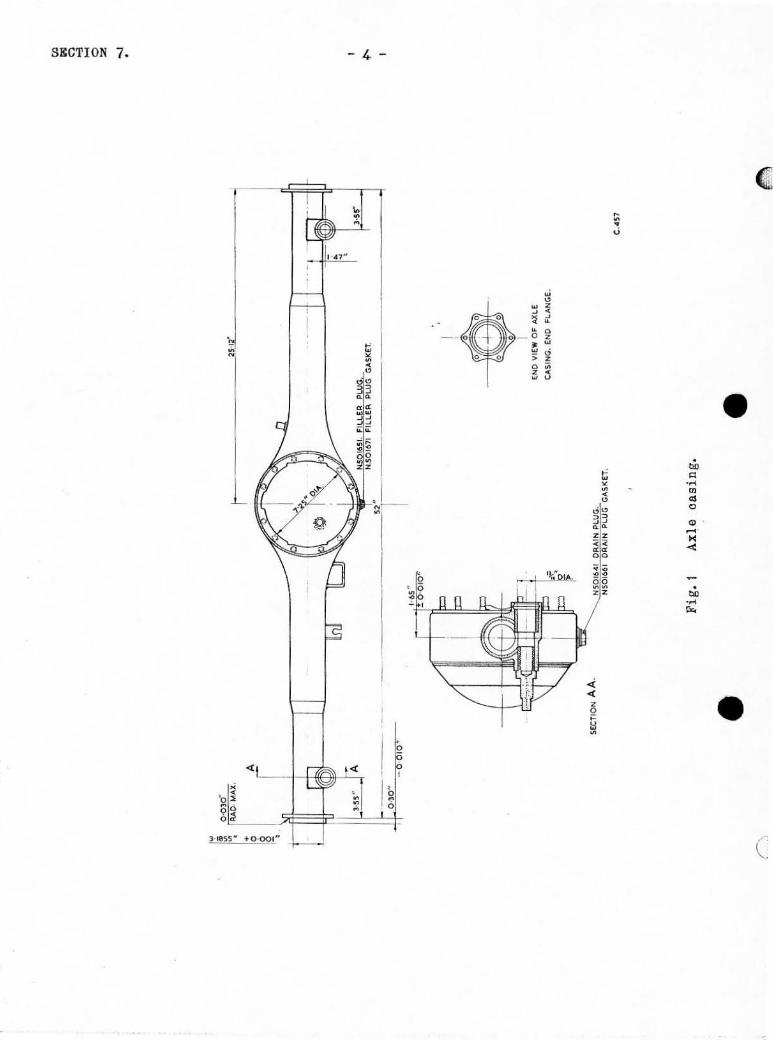
The axle casing. shown in Fig. 1, is of banjo construction, the ends being
machined to l ocate the brake backplntes and t he bearing housin gs . The centre
• f ace i s machined to l ocate t he differenti a l unit. A repl aceable phos phor- bronze
bush is fi tted noar each cnd of t he casing . each being gr ooved t o receive an 01 1
seali ng ring. Th e bushes locate the suspensi on arms Ilnd a stud f i tted to t he
rear of each bus h l ocation receiv es t h o l ower e ye of a telesc opic s hock ab sorber.
A breathor uni t i s s ituated on the top l eft-hand a ide of t he ca s ing, and a
combined oi l filler a nd l evel plug i s l ocated at the ri ght-ha nd s ide of th e domed
cove r. A drain pl ug is Ci tted to the base of the cas in g.
Half shaf t s • A singl e- row ball bearin g and a s pring-lip t ype sea ling ring are fitted
within each bearin g hOll s ing. theso being secure d in position by a ri ght-ha nd or
left-hand t hreaded r eta ini ng ring. A tabwashered r etai ning nut s ecures the
half-s haft i n the bearing hOllsing.
The left- hand shaft is s horter than the ri ght-hand s haft nnd a l so has l oft-
hand thread s ; in all othe r r espects. the s haft s are identica l.
------ --
SECTION 7.
CROWN WHEEL
eE VEL GEAR
BEVEL P I N IO N
CRO WN WH EEL M OU NTING
- 6 -
OIFFERENTIAl GE AR HOUSING
LOCKING PLATE
Fig. 2 Di ff o r en tinl gea r .
Fi g. ) Rear suspe ns i on system.
COM PAN ION FLA NGE
BEARING HOUSING
BEARING CAP
LOCKING RING •
• (

(
•
• (
- 7 - SSCTION 7.
Differential gearbox unit and rear ball joint
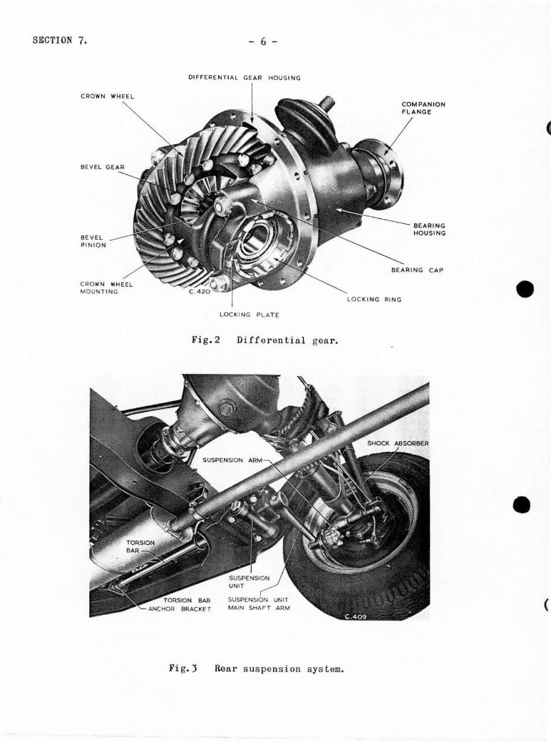
Fig. 2 illus trates the cons truction of the differential gear. The differ-
ential gear housing is secured to the front faee of the r oa r axle casing. t he
driving pinion bein g mounted in two taper roll e r boarings housed in the bear i ng
hous ing. The bearings are separated by a di s tance piece and di stance washers.
Forward of the front bearing i s another di stance washer ; the com pani on fl ange
(which has an integral dust seal) is mount ed on se rrations on the front end of
the pi ni on . A tabwashe red r etain i ng Dut secu r es the companion flan ge to t he
pinion, and the pinion and its bea ring in t he bearing housi ng. An oil sea l
fi tted in the front end of the hou sing embraces the s hank of the companion
fl ange. Pini on adjus tment in r e lation to the differentia l crown wheel is
effected by a n adj ustable washer fitted at the joint f aces of the bearing hous in g.
The crown ""heel is secur ed to the crown whee l mounting by twelve bolt s, nuts
and sp l i t pins . Aper ture s in the mounting provide for in se rtion 01' remova l of
the differential beve l pinions and gea r s . A bronze thrust wa s he r for each bev el
gea r i s l ocated i n a r ecess in the mounting, \~h i1 e semi - sphe rical bronze washe r s
t a ke the th rust of the beve l pi n ions whi ch are fr ee ly mounted on the pinion
spind l e . The s pind l e i s drilled at one end to receive the l ock pin which i s
sc r ewed in to the c rown whee l and l ocked with a s plit pin .
Tho diffe r ential assembly is s upported by taper roll e r bearings l ocated in
bearing caps on eit he r s ide of the differen tia l gear housi ng, side adjus tment
bei ng prov ided by locking rings. which are l ocked by l ocking p lates s ecured in
position by bolts and s pring was hers .

SECTION 7. - 8 -
Su spens ion
General
The rear suspension employs long itudina l torsion bars linked by the main
shaft arms of the s us pensi on units on the chass is frame to the s us pens ion arms
fitt ed in the rear axle easing. Sus pension i s stabilised by the triangular
attachment unit which is secured to a ball joint at the top of tho differential
gear hous ing and i s pivo ted laterally to the top of the chass is fra me roar cross
membe r. Damping of the sys tem i s effected by hydrauli c tele scopic shoc k
abs orber s . The sys tern can be seen in Fi g. J.
To r s i on bars
The torsion bars are lOcated on oach si de of t he car, at the rear, along tho
inside of the chass i s s ide membe r s . They are left-hand and ri ght-hand and are
c lea rl y marked "Lit or "Rn on t he rea r ends . Und e r no circums tances mus t they be
a ssembled incorrectly. Kach bar i s se rrated at both ends; the front end en-
gages an anchor bracket secured to No. 2 chass is c ros s member. while the rear end
engages se rrations in the boro of the suspens ion unit main s haft.
ba r s have 25 se rrations at the front end and 27 a t the rear end;
Both torsion
t hi s provides
a ve rni e r adjustment for se tting. The r ea r end of each bar i s drilled and
tapped 5/ 16 in. B. S . F. to a ccommodate an ext r ac tor. and a half-round annul a r
groove located half-way along the r ear sorrations accommodates the bolt which
secures the bar to the suspen s ion uni t mai n s ha ft.
Sus pens ion units
These identical uni ts arc illustrated in Fi g.). a section view being g iven
•
• c
- 9 - SECTION 7.
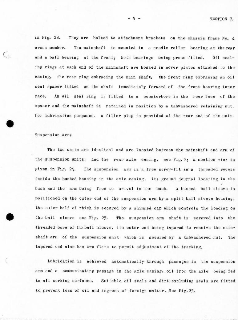
in Fig. 28. Theyare bolted to attachment brackets on the chassis frame No. 4
cross member. The mainshllft is mounted in 11 needle roller bearing at th(' roar
c Ilnd 11 ball bearing at the frontj both hearings bein g press fitted. Oil seal-
ing rings nt onch end of the mainshllft are housed in cover plates attached to the
casing. the rear ring embracing the ma in shaft, the front ring embracing nD oil
seal SpaceI' fitted on the shaft immediately forward of the front bearing inner
r a ce. An oil soal r i ng is fitted to a counterbore in the rea r f llce of the
s paceI' Ilnd the mainshaft is r e ta ined in position by a tllbwas hered r etai ning nut.
For lubrication purposes, a filler plu g is provided at the rear end of the uni t.
• Suspensi on arms
The two un its are id entica l and are located between the lliainsha.ft and a rm of
the s us pen s ion units. and the rear axle cas ing. see Fig.3 -; a section view is
given in Fi g . 25. 'rhe s us pens ion a rm is a free sc r ew-fi t in a th readed r ecess
inside the bushed hou sing in the axle casing. it s g round journal locating in the
bush a nd the arm bein g f r ee to swivel in the bush. A bu shed b a ll s l eeve i s
po s itioned on the outer end of the suspension arm by a sp l it ba ll s leeve housing,
the outer half of which is secu red by Il sh immed cap which con t rols the l oading on
• the ball sleeve see Fi g. 25 . 'rh e s us pens ion arm s ha ft is s crewed into t he
t hreaded bore of the ball sleeve, its out er end being t a pered to receive the main-
shaft arm of the suspension uni t which is secured by a tabwashered nut. The
tapered end al s o has two fl ats to pe rmi t adj ustment of the trackin g.
,"
· Lubrication i s achieved automaticall y through passages in the suspension
arm and a commun icatin g passage in the ax le casing. oi l from the axle being fed
to all working surfaces. Suitab le oil seals and dir t-excluding seal s are fitted
to prevent loss of oil and ingress of for eign matter, Sce Fig.25.

SECTION 7. - 10 -
Tolescopic shock absorbers
For infonnation on these units, ref e r - to page 7 oC Seotion 6.
OIL CAPACITY OF REAR AXLE
Initial filling ••• 4 pints (2'3 litres).
Drain and refill ..• J pints (1-7 litres).
MAINTENANCE
At first 500 miles (BOO k.m.)
Drain a nd refill the r ear ax le.
After first 1.500 mi l es ( 2.500 k.m.)
Drain and refill the rear axle.
After every 3.000 miles ( 5,000 k.m.)
Drain and refill the rea r axle.
1.
REMOVING AND REFI ·rrING HALF SlL\~'TS
Removing
Jack up the car, then remove the road wheel a nd brake drum. see Section 10.
2. From behind the brake backplnte. r elease the tabwashers and r emove the s ix special bolts.
•
• (

(
•
• c
o o o
- 11 -
Fig.4 Vii t hd rawin g ha lf-s haft.
SP"NNER TFN .~22
Fig. 5
WASI-iER
Rear hub assembl y.
SECTION 7.
-- - ..,.
SECTION 7. - 12 -
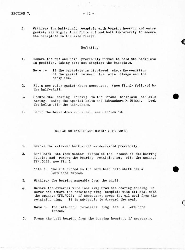
J. Wi thdraw the half-shaft complote with bearing housing and outer ga sket, see Fi g.4. then fit a nut llnd bol t temporarily to secure the backpl nte to the axle fl a nge.
Heri tUng
1. Hemovo the nut Dnd bolt previou s ly fitted to hold the backplnte in pas i tion. t ak in g ca r e not di s pl ace the back plate.
Note :- If the backplnte is displaced, check the condi tion of the gasket between the axlo flange and the backpla te .
2. Fi t a new oute r gasket wh e r e necessary. ( scc Fig.4) foll owed by the half-sha ft .
J. Secure the bearing housi ng to the cas in g . usi ng the s pecial bolt s and the bol ts wi th the tabwllshcrs .
brake backplate and tnbw lI.she r s N.50141t1.
a xle Lock
4 . Rcfl t t he brake drum and whee l , see Section 10.
HEPLACING HALh'-SIlA~~'r BEAIUNGS on SEALS
I. nernov e the r e levnnt ha lf- s ha ft ns described prev i ously.
2. Bend back the lo ck washer fi Lted to the hous ing and remove the bearin g retaining TFN.5022 . sec Fi g. 5.
recess of nu t with
the the
Note:- The nut fi tted to the lef t - ha nd ha lf-shaft has 8.
l e ft - ha nd thread.
bea ring spanner
J . Wi thdraw the bearing a ss embly from the shaft.
4. Hemove the external wire l ock rin g from the bearing hous ing , unsc rew and r emove the retai nin g ring complete with oi l seal with the s panner TFN.502} ; if necessa ry. press the oil seal from the r etaining r ing. I t i s advi sable to di scard the seal .
Not e : - The l eft-hand reta ining ring has a lef t-hand thread.
5. Press the ba ll bearing from the bearing hous ing. if necessa ry.
•
• (

(
•
•
- tJ - S&CTION 7.
Th o followin g is the sequenc e of operations for re-assembling th e b ea ring
hou s ing :-
1. Clean all parts thorou ghly.
2. Inspoct the botHing l ocation shoulder in the hou s ing, remove any
J.
4.
5.
burrs then press the bearing right home in the hous ing. During the operation, avoid damage to the bearing.
It is advisable to fit a new oil seal to the r e taining rin g. Press the seal in to the r e tainin g ring lI'i th the open end up-wards. keoping it squa r e wi th the bo r e . Never apply the l Oll.d to the r oa r face or " dishing" may occur. Screw the assembled seal and r etain ing ring into the hou s ing and ti ghten wi th tho s pecial s pa,nner TFN. 502 J. Repl ace the wi r e l ock ring. If the h o l es in the hous in g and r e t a ining rin g do no t r egis t e r. drill a n e w holo half-way into the reta ining rin g . u s ing a No.4~.
(0'08 6 in. or 2 ' 18 m. m. ) drill.
Caution' - Do not d ri ll th rou gh the ring in to the oil seal.
Fit the hou s ing _a ssemb l y to the ha lf- s haft. b ea ring f ace i s ti gh t a ga in s t t he s hou l de r of
e nsu ring Lho t the th e s haft.
Fit the ti ghten washer.
r e taining nut l ock wash e r ov e r the shaft llnd s crew up and of the lock the retaining nut. Be nd up two s ides
us ing the tool 'N'N . 50 24.
6 . Fit the ha lf-shaft t o the ax l e as desc ri bed previou s ly.
DH'FEIlENTIAL GEAHOOX UNT ·r . AND BALL JOINT ASSEMBLY
Ge ne r a l Data
Ori ve •. • Spi ral bevel.
Diff e r en tial. .• Two s tar beve l.
Crown whee l ••. . . . J9 t ee th •
Drivin g pinion. 10 t ee th.
Ra ti o •.. ... J' 9 :
Bcarings _ Ta pe r roll e r.

SRCTION 7. - 14 -
Pro-loading of bearings
Crown wheel boarings These must be pro-Ionded by means of the screwed lockin g rings until a turning moment of 4 lb. in. (715 "4 gr8JDJl.8S c.rn.) is just hold . The driving pinion must be 1I'i thdrawn from engagement during the set ting operation.
Driving pinion bearings. Prelonding of these bearings is controlled by distance washers and distance pieces of varying thickness and length. These mu s t bo se l ected to ensure that a torque of 8- 10lh.in. (1430 ' 8-1788 ' 5 grammes c.rn.) is roquired to rotate the driving pInIon whon thi s uni t is assembled and lubricated prior to meshing it wi th the crown \~heol.
Backlash (Crown "heel and pinion) 0·006 in. (O ·1 5m. m. ).
End-float of differential bevel gea r • __ 0-002 in. (0 -050 m. m. ).
End-float of differentia l beve l pini on • . . 0'002 in. (0'050 m. m.).
Crown wheel "run out" 0 ·002 in. maximum (0'0 50 m.m. ).
Replacing driving pinion oil seal
1. From below the car. disconnec t the propeller sha ft rear universal joint at the companion fl ange .
2.
J.
4.
Unlock and remove the five nuts secu rin g the bear ing housing to t he differential uni t a nd wi thdraw the bearing hous ing ccmplete. Take care to r e t ai n the adjustab l e wa s he r(s) fitted at this joint as its thickn ess ha s a lready been d ete rm i ned.
Locate the bearin g housing in the vice plate spanners TFN . 5054 and TFN.5055. see Fig. 7. ing nut and tabwashcr see Fig.6.
TFN.5052. and us ing remove the retain-
Using the extractor TFN. 8450. withdraw the companion flan go from ita pinion. followod by the distance was hor.
5. Wi th the rear face of the bear i ng housin g sui tably supported. pres s out the driving pInIon. The bearing inner race and rollers and the di s tance piece and distance 1I'a sl1'o: r s hou ld r ema in on the pinion. 'fak e care to retain the distance piece and distance washer s ince t h ey are selected si ze.
•
• c

BEARING HOUSING
(
• DRIVING PI NION
Fi g.6
• (
Fi g. 7
- 15 -
COMPANION FLANGE
C.405
TAB WAStIER
Dif f e r en tial bearing hOll s ing a ssembl y .
.o,.
~;"--'}~,.... __ :::,~ :~"~ PINION _ BEARING HOUSING
C 487
Removing driving pinion.
S&CTION 7.

. . ,.
SECTION 7. - 16 -
6. nevers c the bearing hou s ing llnd press out the oi 1 seal toge ther with th e inner rac e and r o llers of the fr ont bearing.
To reass emble proceed as fol1o~s referr in g to Fi g.6.
1. Refit the pInIon complet e with the r ea r inner race , the distance piece and the distan ce washer to the bearing housi ng.
2. Press the fron t bearin g inner r Ace and roller assembly on tho pinion and fit the front distance wa s her.
J. Prcss a new oi l seal in to po s ition. lip inwards.
4. Press on the companion f1nn ge. refi t the special was her, t nbwashe r and nut.
5. Again u s ing the vice pl ate TFN.5055 , ti ghten and l ock for the pro- l oading figure .
TFN.5052 and spanne rs TFN.5054 and t he nut. Haf e r to t he Gene ra l Data
6. Re fit the bouN ng housin g, \Iith t he adjustable was her i nterposed , to the difforentia l unit a nd secure it with t nbwas hcrs and nu ts .
7. ile-conneet the pro poller sh:lf t , 'ea r universa l joint to the compa nion flan ge.
ilcmoving and r ef i t tin g dif fcr en t ia l gea rbo x h ousing
In ordc r to remove the di f f e r en t i a l gea r hOlls ing , it is nccessary partia 11 y
t o wi thdraw both half-shafts. "n e s equence of operations is as foll ows :-
1. Drain the r ea r axle, jack - up the c a r and s u ppor t the chass i s frame; avoid damage to the pct r ol a nd hydraulic s ys t em pipes. Remov e both rear r oad wheels.
2 . Withdraw the ha l f -shaf ts with their r es pecti ve bearing assemblies as desc ribed previous l y.
3. Ha ise the axle sli ghtly by means of a jack. He lease the tabwasher a nd remov e t he nut secu ring the attachment unit t o the ball joint a ssembly; manipu l ate th e jack until the ax le i s in a neutra l pos i tion , then pa r t the attachment uni t from the ball jOint.
•
•

_ .. ,
f\ •
DIFFERENTIAL GEAR HOUS ING~
LOC KING RING
BEARING CAP
THRUST
BEVEL PINION
I t::tr' " CROWN WHEEL ! MJI ,[:~l
c, o"' WMm c:; ~~----,ll1 MOUNTING Ill~ I
8E,f.,RING CAP
LOCKING PLATE BEVEL GEAR
PINION SPINDLE
DRIVING PINION
LOCKING RING GEAR SP INDLE SPHERICAL THRUST WA SHER
•
DISTANCE WASHER ( SELECTIVE)
BEARING HOUSING
COMPANION FLANGE
OIL SEAL
CA06
SPECIAL WASHER
TAB WASHER
Fig. 8 Di ff e r entia l gea r box a ss embly.
(\
""
'" 1'5 ., ~ o z
:-'

SECTION 7.
4.
5.
- 18 -
Di sconnect ion flange gearbox.
the propeller shaft universal joint from and push the propeller shaft forward
the complln towards the
Release the t a bwashers. remove the nuts goar housing to the axle casing and axle.
securing draw it
the differential forward from the
Adopt the followin g sequence to refit the assembly to the axle.
1. Cl ean the joint faces on the axle casing and the gcar housing.
2 . Fi t a new gD.skct.
J . Refi t the Ilssclnbly to the axle casing. replace the tllbwashc l' s and nuts a nd ti ghten evenly.
4.
~otc "- Th e nut at the top of the casing mu st be fitted prog ressi vely during fi tment of the housing.
Make any then lock
necessary backlash checks the securing nuts with the
as descri bed s ubsequently tnbwnshcrs .
Connec t the n t tactonen t uni t to differential gea r housing. nnd \w s he r.
the ba] 1 joint secure it with
on top of the a nu t and tnb-
5. Reconnect tIle propeller shaft universal joint to the companion flange.
6. Remove the t ~Ill porary retaining nu ts from the flanges and refit the half-shafts, brake drums as described previously.
brake boekplate and road wheels
7. Top up the rear axle wi th approved oil.
Dismantling diffcrentinl gearbox unit
With the diff e rential gea rbox unit out of the car, di smantle it as follows "-
1.
2.
3.
Locate and bolt the compl ete assembly with fixture TFN.505J. see Fi g. 17.
Remove the locking ring lockin g plate from both bearings caps and break the l ocking wire from the bearing cap nuts.
Remove the bearing cap wheel mounting to gether
nuts and caps and l ift out the erotm wi th the locking rings and beal'ings .
•
• c
,

(
•
• (
COMPANION FLANGE
0"
TAPER ROLLER BEARING
OI STANCE PIECE
- 19 -IN NER ROLLE BEARING
SECTION 7. LOCKING RING BEAFIING CAPS
DIFFERHIlIAL
, .. . ,,~, .. ~-. ;~ \ o ' , '0C< "'"
~ 'ow"" "'"
BEARII'+G HOUSING A DJUSTABLE WASHER
Fi g. 9
CRO WN WH EEL
\ . .,...::::;. -
THRUST WA SHER
Different jal componen ts .
CROWN WHEEL MOUNTING
/
~~~ ~ .e ~ ~I!I "\ f J
~I' SPHERICAL THRUH
""""'~ / WASHER
-: I' TIoIRUST WASHER It '- (NOT NORMALLY REMOVEO\
BEVEL PINION ~ \. BEVEL GEAR ;... -- '" \,. Vr.:~ .. m"" / .~ J! ~ <: .204
, \
'" (NOT NOI'IMALLY --
AEMOIfEO) \
" PINION SPINCX..E ~ ~ _~.,
---~/,\, ) BEVEL PINION -
Fi g. 10 Cr own ~hcel mo un t ing components .
SECTI ON 7.
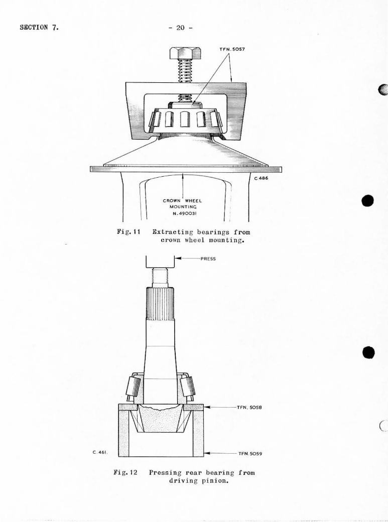
Fi g. 11
~'i g. 12
- 20 -
CROWN WHEEL
U OO IH INC
N . 4 90031
Extractin g bearin gs from crown wh co 1 moun t i ng.
C486
Pressing rear bearin g from drivin g p i nion.
•
• c

•
• (
4.
- 2 1 - S&CTI ON 7.
Unlock and remove the nuts securin g the bearin g housing t o the differontial gearbox hou s in g , then wi thdraw th e b earing hous in g complote. 'fake care t o r e t a in the adju s t a bl e washor(s) fitted a t the joint face.
Dis man tl ing crown whee I moun ting
nefcrrin g to Fi gs . 2 and 10 proceed as f o llows .
1. Remove t he split pin s, nu t s and bolt s t hen r emov e the crown wheo l from t he moun t i ng.
2. Secure the fixture TFN.5056 ( s ce Fig. Ut-) i n a vi ee then s ecure the mounting to the f ixture .
J . Remove the s plit pin r etain i ng t he pin i on s p indl e l ock pin a nd un sc r ew thc pin. Drift out t he pinion s pindl e.
4. Manoeuv r e each pini on un t il OppOSl te one of t h e large a per t ures in the mounting ond withdraw them, toge t he r with t he ir respectiv o sphe ri ca l thrus t woslle r s . Labe l th e pIlllons and thru s t wa s he r s to record thei r correc t r elative pos i ti ons .
5. Pus h each bevel gea r i n turn to the c en t re of the cas ing a nd r emove throu gh the l a r ge r a pe rture.
6. If th e t a per rollers are unse rvi c ea ble , r emov e t hem from the crown whee l mounting s pi got us ing t he too l TFN.5057 a s s hown in Fi g.t 1.
7. Ph os phor bronze thrus t wa s h e r s are pressed i nto a r eces s in the beve l gear location. TJl ese are n se l ec t i ve ass embly nnd s hould only be removed if r eplacemen ts are ne cessnry . Small hol es a re provided t o enabl e them to be t ap ped out but thes e are onl y accessi ble ';I"hen the r o ll e r benrings hav e b een r emoved .
Di s man t ling bearing hous ing
Di smantle t he hou s ing as desc ribed on page llj. und er nUeplacing drivin g pin-
ion oil s ea l-.
If t he r oll e r bearings a re to be r epl aced, i t will be necessary t o r emo ve
both t he ouie r r acos from th e bearin g hous ing nnd the inne r race a nd r o ll e r
a ssembly from the driving pin i on by t he f ollowin g me th od : -

SECTION 7.
PRESS
Fig. 13
Fi g. 1/ ...
- 22 -
1;";4-·,., .. , .. 5062
-~
G i f-T'1
=1'iec;'/"'-..~==:::"~1.··iDl .~ 4· 1'0: 4+---l;ti'l
L:~"lL ________ ' 1'1",it,~ T.F.N.S071
C",79
Pressing bearing outer r aces from bearing housing.
TFN . 5064
C.477
Checki ng bevel pinions ilnd gears .
•
• c

c
•
•
- 2J - SECTION 7.
1. Us ing the t.ools TFN.5058 and TFN.5059. r emove the roller race as s hown in Fig. 12.
2. Us ing the spigots TFN.5060 and TFN. 506 1 and the or TFN.5071. press out the bearing outer races fir s t) a s s holfn in Fig. I J.
Reassemblin g crown wheel mounting
ring TFN.5062 (larger race
Make s ure that all components are scrupulou s ly c l ean and that all oil
pas sagos are unobstructed . It is preferablo to use petrol to clean these oom-
pOD ents finally, since this will facilitate the s ubsequen t assembly checks .
Conunenoo re-assembly in the fo ll ol\"i ng s eq ue nce, r e f e rring to Fi g . 10,
1. If the tw o phos phor bronze t hru s t wa s he r s have not been dj scarded. l eav e them in posi tion pending the resu l ts of the s ubs equent end- float chec k. If t he wa s hers have b een di s c a rdcd , fit two n ew washers s li ghtly thicker than those taken out. Thrust wa s hers are avui l nble i n the following thicknes ses :-
0 · 102 in. ( 2 · 55 m. m.) O· 110 in. (2· 75 m. m. ) 0 · , 04 in . (2· 6 m. m. ) O· 1 12 in. (2·8 m.m.) 0·105 in. (2·0) m.m. ) 0·114 in. (2 · 85 m. m. ) 0·,07 in. ( 2·68 m.m.) 0· 11 6 i n. (2·90 m. m. )
2. With the crown wheel mounting i n the vice fixtur e TFN.5056. in-s ert the bevel gea r s .
J. With the spherica l t hrust wa s hers in po si tion. fit the bevel pinions t o the mounting. If the s phe rical thru s t washers removed wh en dismantlin g have be en di scarded. a sel ection o f thrust was hers are avai labl e in t he followin g thicknesses
0 ·2 19 0·221 0 ' 228
in. in. in.
m. m. ) m. m. ) m. m. )
0· 2J l 0·2J4
i n. 1 n.
m. m.) m. m. )
With these component s in pos iti on, ins e rt the pinion spindle aligning its ho l e with the lockin g pin position.
... - ......... ~--~~ ~.-~-~-~ - ---_ ..... __ .. - . . -". _. _. -- .... _------... _- - - ~~.-----.-~
SECTION 7. - 24 -
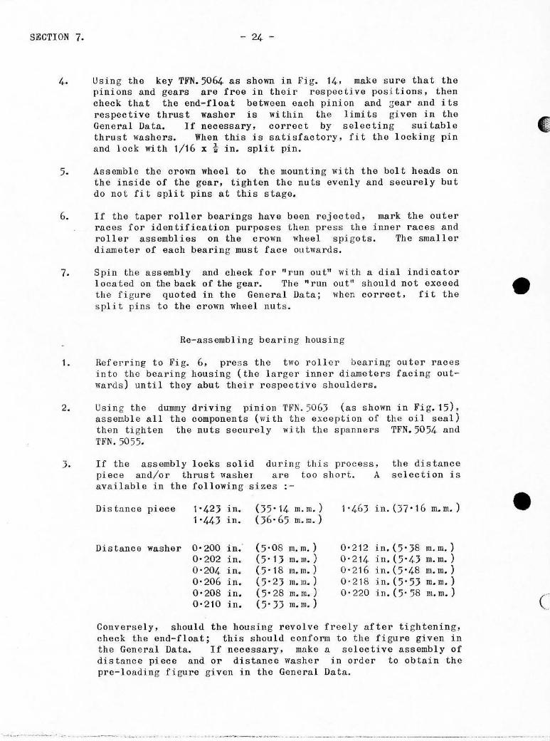
4. Using tho key TFN. 5064 as shown in Fig. 14. make su r e that the pinions and gears aro f r ee in their respective pos i tions. then check that the end-float botween each pinion and gear and its respectiv~ thrust washer is wi thin the limits given in the General Data. If necessary . correct by selecting suitable thrust washors . When this is satisfactory. fit the locking pin and lock wi th 1/16 x -t in . split pin.
5. Assemble the crown wheel to the mounting wi th the bol t heads on the inside of the gear, tighten the nuts evenly and securely but do not fit spl it pins at this stage.
6. If the taper roller bearings have been rejected, mark the outer races for identification purposes then pre ss the inner races and roller assemblies on tho crown wheel spigots . The smaller diameter of each bearing must face outwards .
7. Spin the assembly and check for "run out ll wi th a dial indicator located on the back of the gear. The "run out lt should not exceed the figu re quoted in thc Gonera l Data; when correct, fit the spli t pins to the crown whee l nuts.
Re- assembl ing bearing housin g
1. Referr ing to B'ig. 6. press the two r oller bearing outer races into the bearing hous ing (the larger inner diameters facing outward s) until they abut thei r respee tive shoulders.
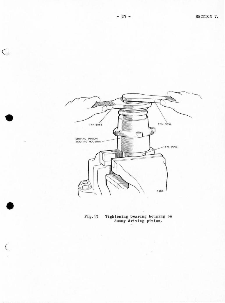
2 . Using the dummy driving pinion TFN. 5063 (as shown in Fig. 15), assemble all the components (with the exception of the oil seal) then tighten the nuts securely wi t h the spanners TFN.5054 and TFN.5055.
J. If t he a ssembly l ocks so l id durin g tilis process, the distance piece and/or thrust washeT are t oo short. A selection is available in the fol l OWing sizes : -
Di stance piece 1'423 in. 05'14 m. m. ) 1 ' 44J ,no D6· 65 m. m. )
Dis tance WAsher 0'200 in. (5'08 m. m. ) 0'202 in. (5' I J m.m.) 0'204 in. (5' 18 m.m . ) 0'206 in. (5'2J m.m.) 0'208 in. (5'28 m.m.) 0·2 10 in. (5·n m.m.)
1'463 in .(37·16 m.m.)
0'212 in.(5·38 m.m.) 0' 2 14 in .(5 · 43 m.m.) 0'216 in. (5°/ .. 8 m.m.) 0'218 in.(5·5J m.m . ) 0-220 in. (5' .58 m. rn.)
Conversely, should the housing revolve freely after ti ghtening , check the end-float; this should confonn to the figure given in the General Data. If necessar y, ma ke a selective assembly of distance piece and or distance washer in order to obtain the pre-Ioading fi gu re given in the General Data.
•
• c
•
• (
" "
DRIVING PINION SEARING HOUSING
Fi g.15
- 25 -
lFN 50~4
Ti ghtening beari ng hous ing on dummy driving pini on.
SECTION 7 •

SECTION 7.
•
Fig.16
- 26 -
POSITION OF MARKING CORRECT
PINION ,.WAY FROM CENTRE OF CROWN W1-I£EL
Diagram of tooth contact_
I
•
• (
c
•
•
- 27 - SECTION 7.
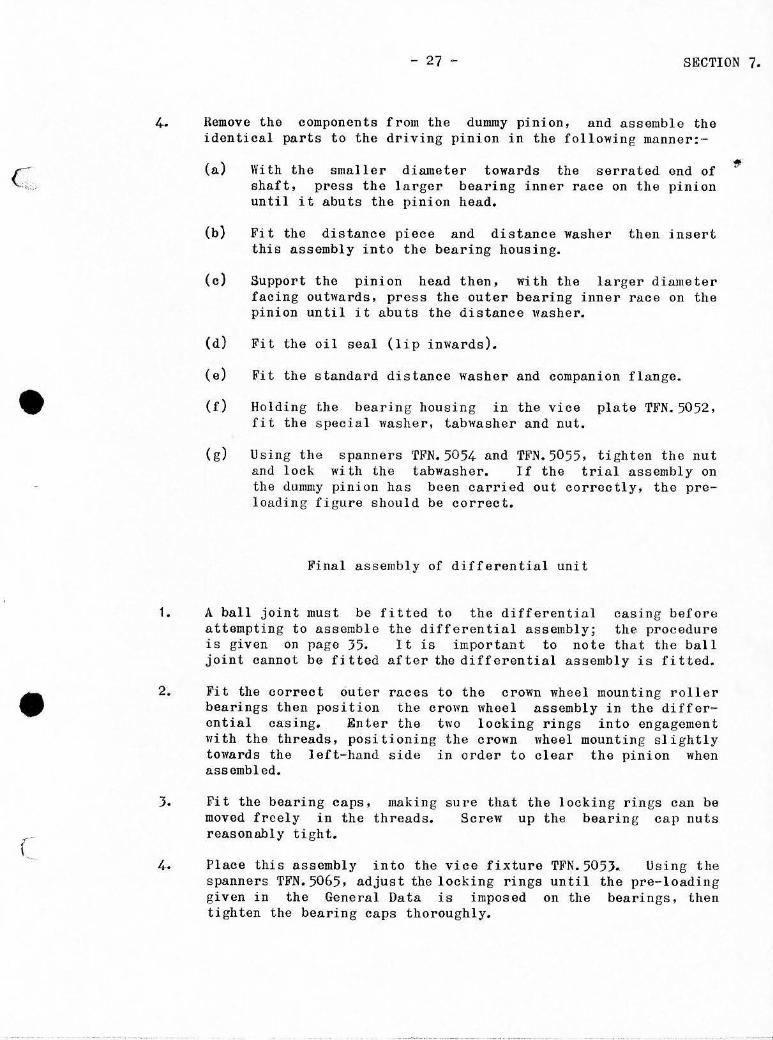
4. Remove the components from the dummy pInlon, and assemble the identical parts to the driving pinion in the following mllnner:-
(a) \Vi th the smaller diameter towards the serrated end of shaft. pross the larger bearing inner race on the pinion until it abuts the pinion head.
(b) Fit the distance piece and distance washer then insert this assembly into the bearing housing.
(c) Support the pInIOn head then. wi th the larger diameter facing outwards. press the outer bearing inner race on the pinion until it abuts the distance washer.
(d) Fi t tho oil seal (l i P inwards).
(e) Fit the standa rd distance washer and companion flange •
Holding the bearin g housing in the vice plate TFN.5052, fit the specia l washer, tabwasher and nut.
(g) Using the spanners TFN.5054 llnd TFN.5055. tighten thc nut llnd lock wi th the tabwasher. I f the trial assembly on the dummy pinion ha s been carried out correctly. the preloading figure shou ld be correct.
Final as s embly of differential unit
1. A ball joint must be fitted to the differential casing before attempting to assemble the differentia l assembly; the procedurc is given on page 35. It is important to note that the ball joint cannot be fitted after the differential assembly is fitted.
2.
} .
Fit the correct outer races to the crown wheel mounting roller bearings then position the crown wheel assembly in the differential casing. Enter the two locking rings into engagement with the threads. po sitioning the crown wheel mountin g s li ghtly towards the left-hand side in order to clear the pinion when assembled.
Fit the bearing caps, making moved freely in the threads. reasonably tight.
sure that the l ocking rings can be ScreW up the bearing cap nuts
4. Place this assembly into the vice fixture TFN.505J. Using the spanners TFN.5065. adjust the locking rings until the pre-loading given in the General Data is imposed on the bearings, then tighten the bearing caps thoroughly.

SECTION 7. - 28 -
5.
6.
Noto"- The pro-loading figure can be obtained fairly accurately by setting the lockin g so that the assembly is free to rotate wi thout any side play, then tightening each locking ring onc serration further.
Using a dial indicator, check on the crown wheel rear face for 11 run out"; this must not exceed the figure given in the General Data. When satisfactory, split pin the crown wheel nuts.
Fi t the adjustable washer over the bearin g housl ng studs. Thi s washer Cllll be adjusted by peeling necessary number of 0'002 in. (0'05 m.m.) IllDlinations.
retaining off the
7. Fit the bearing housing assembly, check that there is backlash botween the crown wheel and pinion. then fit Ilnd ti ghten the nuts evenly.
8. Wi th the handle TFN.5066 inserted into wheel mounting as shown in Fig. 17, check
one side of the backlash.
the crown
9. Obtain the backlash figure given in the General Data by moving the lockin g rings in the bearing caps by egual increments; this will ensure that pre-Ioading is maintained. Measure the backlas h wi th a dial indicator.
10. Check the tooth contacts by lightly SJ:learlng the pinion teeth l';i th marking compound and rotating the crown wheel and pinion together, noting the contact of the teeth as shown in Fig.16 . Correct as necessary to obtain the recommended contact by altering the thickness of the adjustable washer fi tted to the bearing hou sing join t then re-adjust the backlash.
11. When adjusted correctly, fit the lock plates to the rings. the locking wire to the bearing cap nuts and washers to the bearing housing retaining nut s .
REMOVING AND REFITTING REAR AXLE
locking the tab-
1. Jack up the car and place chassis stands under the chassis frame side members, well towards the rear wheels, avoidin g drunage to the brake fluid and fuel pipes.
2. Remove both rear wheels.
•
• (

- 29 - S&CTION 7.
----_ TFH 5066
• - - - --___ TFN 5053
• Fi g. 17 Tool s for check ing crown whoe l backlas h.

ggCTION 7.
J.
5.
6.
- JO -
Jack up Ilnd s upport the axie then dotaci. of each snubbcr s trap by reruoving the shakeproof wllshors. washor plate. PAcking
Detach the s hock absorbers from the axle.
the rearmost anchorage tua i D. S. F. bolts,
washers and nuts.
Nanipulll.tc the jack until the ax l e with no lond on the torsion bars . pasi tion.
is in 11 neutral position, then s upport the Ilxle in
i. o . this
Referrin g to Fi g. 20 . detach tho atta chment uDi t nnd socket joint on the differontia l gearbox posi tion it so that it is out of the way.
from the ball hous ing and
7. Disconnect the rea r universal joint from the companion flange.
s. Disconnect the brake fluid flexible pipe from the centre of the three-way union on the differenti a l gearbox hous ing; detach the gaiter then di sconnect the hand brake operatin g cabl e from the brake operating lev er.
9. Unlock the tnbwas her, unscrew a nd remove the nut, th en us ing extractor T~'N . 8039 . break the tape r joint between the s us pensi on uni t main s haft a rm s and t he suspension arm shafts . Do not turn the suspension arm s haft since thi s is the adjustment for the rear tracking.
10. DraW the axle to t he rear unti 1 the s us pension arms are clear of their res pective main s haft a rms . Itemove the support s a nd lower the axle to the v round.
To refit the a..:10 , proceed as follow s : -
1. First check the posi tion of the s uspension arms sec Fi g. 25, Le. that there is a clearance of 1/16 in. (1'59 m.m.) from tho axle casing wh en the arm is hanging downwards and the end of the s pindle is level with the inn e r bus h. This setting i s important s ince it forms the initial s e tt in g for the tracking.
2. Manoeuvre the axle until it is be low its location on the car , t hen jack it up until the suspens ion arm s hafts can be located in their res pective mainshaft anns.
J . Enter both sus pens ion arm shaft s into their respec tive mains haft arms , then f i t a tabwasher and nut to the cnd of each s haft And tighten until the taper joints are right home. Do no t lock the nu t s wi th the tabwashe r s un ti I an nl ignm en t check has been made.
4. Connect the attachment unil to the ball and socket joint at the top of the differentia l gearbox hou s in g , fi t n tabwns her a nd nut , then ti ghten and lock th e nu t .
•
•
- 31 - SECTION 7.
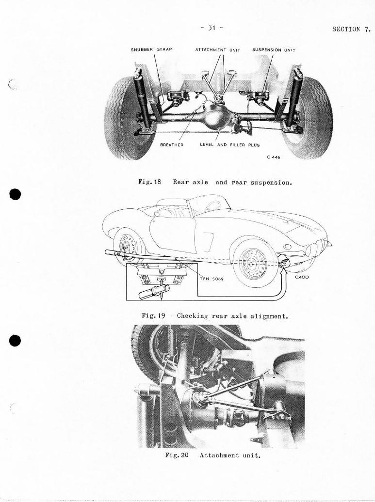
SNUBBER STRAP Jo,TTACHMENT UNIT SUSPENSION UNIT
(
LEVEL AND FILLER PLUG
C 446
Fig. 18 Rear axle and rear suspension .
• ]
_ SOMI
Fig.19 - Checking rear axle ali gnment •
• (
Fig. 20 Attachment unit.
SECTION 7. - 32 -
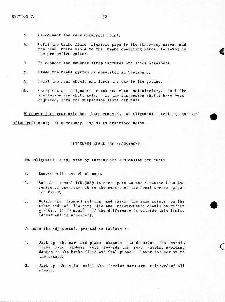
5. He-connect the real' universal joint.
6. Hefi t the brake fluid flexible pipe to the three-way union, and the hand brake cable to the brake operating lever. followed by the protective gaiter.
7. ne-connect tho snubber strap fixtures and shock absorbers.
8. Bleed the brake system ns described in Section 8.
9. Refi t the rear wheels and lower the cnr to the ground.
10. Carry out an alignment check and when satisfactory, lock the suspension arm shaft nuts. If the suspension shafts have been adjusted, lock the suspension shaft cap nuts.
Whenever the rear axle has been removed, an alignment check is essential
~fter refitment; if necessary, adjust as described below.
ALIGNMENT CHECK AND ADJUSTMENT
The alignment is adjusted by turning the suspension arm shaft .
1. Remove both rear wheel caps.
2. Se t the trammel 'rFN. 5069 to correspond to the distance from the centre of one rear hub to the centre of the front spring spigot see ~~ i g . 19.
3. Retain the tramme l setting and check the same points on the other si de of the car; the two measurements should be wi thin ;t1/16in. (1 ' 59 m.m. ); if the difference is outside this limit, adjustment is necessary.
To make the adjustment. proceed as follows
1. Jack up the car and place chassis stands under the chassis frame si de members well towards the rear wheels, avoiding druna ge to the brake fluid and fuel pipes. Lower the car on to the stands.
2. Jack up the axle until the torsion bars are relieved of all strain.
•
• c

c
• ! .
• ( ,
- ,J - S&CTION 7.
3. Unlock the nut securin g the suspension arm s haft to the mainshaft arDl, then using extractor TFN . 8039. break the joint.
4. Unlock shnft gasket
and remove the four nuts cap. Remove the cap but and shims. see Fi g.25.
securing the do not damage
suspension or mislay
arm the
5. Vs ing a spanner OD the (lats provided at tho end of t he s us pens ion arm s haft. turo the shaft in the appropriate direction.
Note: - Turning a suspension arm shaft clockwi s e will draw the adjacent rear wheel forward (i, e . decreases the trammel measurement) and vi ce vers a.
Do not exceed the followi ng adjustment.
Clockwise An ti - 0 l ockld so.
Ma.ximum permi ss ible ! turn. Maximum permi ss ibl e = tur~
rhe adjustment quoted is the mD,ximum pCMUi ss ibl c adjus tment from neutral.
i.e. when the s hnft is flush 'With the end of the ba ll s l eeve. and it i s there-
fore necessary to make e visual check on each s haft; it may be neces sary to
neutralise the pos ition of both s hafts to obtain a da tum f o r correct adju s tment.
I .
A'M'ACHJalENT UNIT
Removing
Jack up and support the car on chass i s s t a nds placed well towards the rear whee l s so that the axl e rests in the s nubber s traps . Ta ke care not to damage the brake or fu e l pipes.
2. Place tl jack centrally beneatb tbe axle cas ing and raise the ax l e s li ghtly.
J. From under the car. unscrew and remove s hake-proof washers from the bearin g the prope ll er shaft tunnel.
the t in . B. S.F. nuts and s pindl e on either side of
4. Uns c rew and remove the two 5/ 16in. B. S. r. bol t s . nu t s and s hakeproof washers and triangular washe r pla t e from each side. s ee Fi g. 20.

SECTION 7.
5.
6.
Rel ease the tllbwas hcr; ball joint a ssemb l y on
- 34 -
r emove the 9/16 in. D.S.F. Dut from the the differontial gea r housing.
Manipul ate the jack until the axle is in a neutra l position then part the attachment unit from the ba l l j o int ass embl y.
7. Removc the nut, bol t Ilnd washor connecting the major and minor arms.
S. Detach both arms Crom the mounti ng spindle s and r emove the robber b earings.
Ref it ting
1 • Coat each ru bber bcaring (insi cb and out) wi th Co] loidal graphi te .
2 . Fi t the bearin gs in t o the l ocations at tho e x tremi tie s of the major and mi nor arms .
3 . }<'i t t h e arms (compl e te wi th the rubbe r bea rings) on thcj r respective spindles Ilt either s ide of the propo ller shaft tunne l , the majo r arm occupying the 10ft-hand spind l e. Mato the fork joint of the two arms . and fi t the bolt, s hake-proof was her and nut; ti ghten the nu t.
4.
5.
6.
7.
Fi t a triangul ar pla t e wa s her t o each t unn e l s pi ndl e . the bolts , was hers and nuts , and t i ghten the nuts.
In s ert
Fi t a nut and Y;ll,.s hor to each s pindle . to the g round and ti ghten the nut s .
Hold the arms pa r a llel
Manipul ate t he axle until uni t can be enga g ed quite Fi t the tabwD,shcr and nut,
the r ear l ocation of t he attachment free l y wi th the ball joint a ssembl y. then li ghten and l ock the nut.
Caution '- Excess l everage on the nut wi ll result in dama ge to t he ball join t a ss embly. A standa rd leng th open-ended spann e r i s s ufficient to t i ghten the nut.
Uem ove the chass i s s tands and 10'1101' the car to the g roun d .
•
•
• (
c
•
• ( ,
- 35 - SECTION 7.
REAlt BALL JOINT ASSEtalBLY
Hemoving and ro[i tting
The rear ball joint cnn only be removed from ins ide the differential uDi t.
It is therefore necessary parti a ll y to withd r aw the half shafts. and then to
wi thdraw the differontial uoi t and to remove the crown "heel mounting from the
differential uDi t. When thi s ha s been done, withdraw the nut and tllbwasher from
inside the differential hou sin g Ilnd tap out the ball bolt with a soft metal drift •
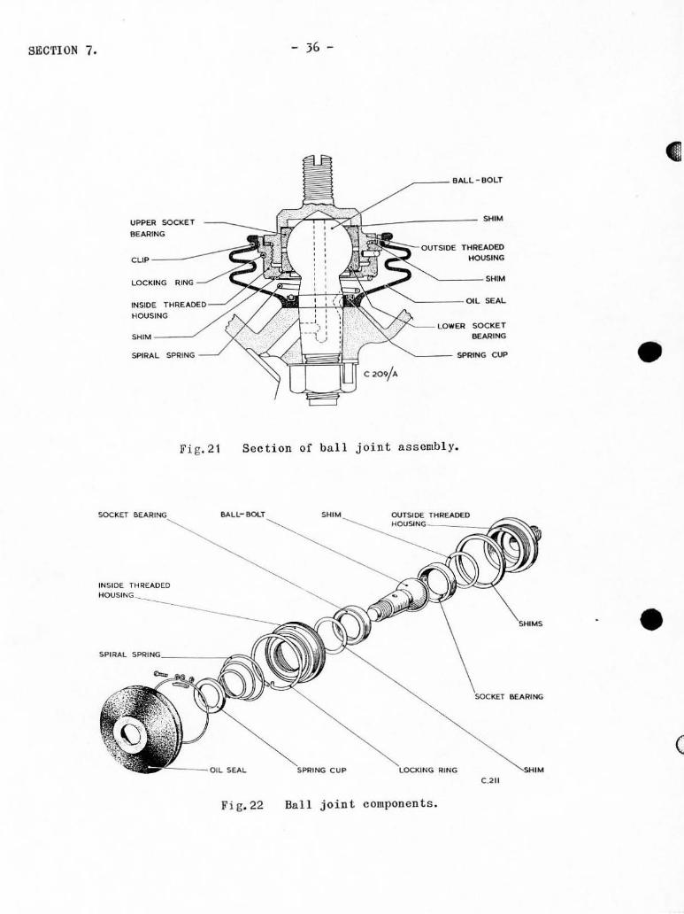
To refit the ball join t, reverse the foregoin g procedure. Ensure thn t the
oil passage in the si de of the ba ll bolt taper coincides with the oil passage i n
the differential gearbox hou s in g, see Fig. 21. Fit the angle tabwll sher from
inside the gea rbox housing, makin g su r e that the tabwas her does not obstruct the
oil feed passage or the oil return groove. Fit tho nut to the ball bolt, then
tighten the nut and lock it wi th the tabwasher.
Complete the a ssembl y of the differential gearbox hou s ing as descri bed on
page 27. then refit the assembly to the rear axle as detailed on page 18 •
Di smant ling and re-assembling
1. Referring to Figs. 21 a nd 22. remove the clip and saddle piece. secu ring the rubbe r oil seal.
2. Withdraw the rubber oil s eal over the tape r of the ball bolt. follow ed by the spiral spring and spring cap.
3. Di sengage the tongue of the locking ring from its location in the Ilou si ng and r emove the ring.
SECTION 7. - 36 -
/ ___ BA,l.L - BOI.T
UPPER SOCKET .------------Jif;~~~~~~~===_--------------BEARING
"',.
LOCKING RING
INSIOE HOUSING
SPIRAL SPRING
Fi g.2 1
THR£AD£D HOU$ING
7'-- LOWER SOCKET BEARING
SPfnNG CUP
Section of ba.ll joint assembl y.
C.2 !!
Fi g. 22 Ball joint components.
•
• (

(
•
•
4.
- 37 - SECTION 7.
Unscrew and remove the housing (ins ide thread) from the hou s ing ( outside thread) us ing the vice plate TFN. 8792 and the ring s panner T~'N . 10085. scc Fig. 2). Retain t he s h i ms fitted betwoen the housings.
Note :- Ins ide each housing i s Lt socket bear i ng which i s shirumed agai nst its r es pective seating in the hous ing. Label these componen ts to ensure corr ect ass embl y.
5 . \Vi thdraw the ball bo1 t from t h e insid e t h readed hous i ng and remove t he uppe r socket bear in g fol l owed by the 9him( 8).
6. I~efit th e outside threaded housing on the i nside threaded housing and tap the face of the inside threaded hous ing on a sui table block un t il t he l ower socket bearing d r ops from its hous ing. Pa rt the hous ings and remov e the bea r in g and shim( s ) •
To r e-ass embl e the ball joint. adopt the followin g proc edure.
1. Fi t th e (;o rre c t shim ( s ), followed by the upper s ocket bea rin g . into th e outs idc threaded housing. prime the ba ll bolt OilWllY S
ll nd in se r t the bolt into the outs ide threaded housing and s ocket bearing.
2 . Fit th (l lowe r soc ket bearing ove r the bal l bo l t and in to t h e outside t hreaded hou s ing.
3 . li'i t the co rrect s h i m( s) on the protrudi ng socket bearing. then fi t t he l arg e s him over the threads of the outs ide threaded hous in g and s crew on the in s ide threaded hou s ing ; t i ghten the hou s in gs securely. aga i n u s in g the vice plate 'TFN. 8792 and the ring spanne r TFN. 10085.
4 •
5.
Check t ha t t here is s ufficient l oading on the ball joint. Some difficul t y may be expe rienced in judg ing the correct -fee l" of the ball joint, sinc e the s ocke ts are su fficiently well mated to r equire a distinct jer k to free the surfaces ini tially. The joint however, s hould be capabl e of mov ement by a fair amount of manua l fo rce on l y. Any necessa r y adjus tme n t i s effected by a l terin g t he s hi ms beneath the cap.
Us ing the ho l e in the inside threaded housing a s a pilot. dri ll into the ou t s ide housing with a No.44 (0'086 in. (2' 18 m. m. )din. ) dri ll t o accept the ton gue of the l ocking ring. Do no t drill ri gh t through the i ns ide threaded hous ing.
6. Ht the lo cking rin g with its tongue locati ng in the hole jus t d rilled.

SECTION 7.
VICE PLATE TF N 1792
~ \
- 38 -
RING SPANNER
Fig. 2J Unscrew ing ba ll j oin t housin gs .
Fi g. 24 Sus pension arm shaft ex trac t or.
•
• (

c
•
•
7.
8.
Fit the s piral spring on to its location on
- J9 - SECTI ON 7.
(large diameter first) over the ball bolt the fac e of the inside threaded housing.
Position the spring cup over the small end of the spring. then fit the oil seal over the bolt and lOCllte it on tho housing.
9. Secure the seal with it s circlip.
Rep] aeemen t8
Any grooving or scoring of the hall bolt and socket bearings render both
the ball bolt and the socket bearings unse rviceable. These parts are carefully
selected and mated during manufacture and s hould not be intermixed. The ball
bolt and its mating socket bearings s hould thus be orderod toge ther .
Faul ts
If any -bumping" is audible when accelerating or braking, check the ball
joint and uttaohlbent unit. To do this, select second gea r. rock the ca r back-
wards and forward s and note any s lacknoss in the attachment unit jojnts on the
ball joint OD the differential gear housing. If there is slackness at the ball
joint adjust the loading by varying the shim thickness •
1 •
2.
SUSPENSION ARM UNITS
Removing
Jack up the rear of the car and place chassis stands beneath eaell side of the chassis frame towards the rear wheels. ensuring that no damage is sustained by the brake fluid or fuel pipes. Lower the car to the stands,
IV) th the jack in posi tion the s nubber straps. then straps.
under the axle. take the wei g ht r emove the rea rmo s t fixtures of
off the

SECTION 7.
J.
- 40 -
Remove the relevant rear wh ee l and brako drum. the half-shaft and backplatc as described on page
then "i thdraw 10.
4. Release its tabwasher then un s crew and remove the Dut troll the suspension arm shaft.
5. Jack up and support the relevant s ide of the axlo then, using extractor TFN.80J9 8S shown in Fig. 24. break the taper joint of the sus pension uoi t .
6. Roll back the relevant side of tho llxie until the mninshaft arm is clear oC the suspension Ill"lll shaft. Remove the oil retainer cover.
7. Hc1ease the tabwashol's and remove the four bolts and the eap at
8.
1.
the f o rward end of the suspension arm shaft. Do not d8JlUlge or mi s l ay the shims and gasket.
Unscrel'l" the suspension arm ( a nti-clockwise) from the axle casing .
As suming 1D0ve the s hims .
IloCi tUng
that a serviced or new unit is to be fitted. first refour screws from the end cap then remove the cap and
Caref ully retain the sh ims a s they are a selected fit.
2. Enter the scrowed portion of the s u s pension arm into the bushed housi ng in the rear axl e casing . sc rew it home. then turn it back s o that there is 11 minimum of 1/ 16 in. ( 1 '59 m.m.) between the end of the bush and the machined lip of the s uspension arm wh e n the arm is in its correct pos ition (Le. the unit is hangin g dowmfllrds). If the clearance is l ess than 1/16in. (1 - 59 m.m.) un s crew the shaft one turn.
J.
4 .•
5.
Refit the s hims. gasket and cap to the forward end of pensi on arm shaft nnd securo with tnbwtlshers and nuts; nuts with the tabwashers.
the suslocI.; the
Fit the suspension arm shaft reta iner cover interposed. Tighten the Dut but leave it
to the IDllin s haft arm. with the oil then fit the tabwasher and nut . unlocked at this stage.
Be fi t the s nubber strap fixtures.
6 . Heri t the backplate. half-s ha ft. brake drum a nd r ear Wheel. then r emove the chassis s tands and 101\'er the car to the gro und.
7. Check the axle alignment a s factory. loc k the s u s pens ion
described on arm s haf t nut
page with
32; its
when s atistnbwas hcr.
•
• (

c
•
•
AXLE
s-.OCI( " '0"'"
- 4 1 -
BUSti
SEALING RING
GASI(ET
BALL SLEEVE HOUSINGS
BALL SLEEVE STOP
BALL SLEEVE
SUSPENSION
CUP (LARGE)
Fig.25 Section of s uspension arm unit.
REAR AX LE C."., _,
SHOCI(
Fig. 26 Torsion bar extractor.
SECTION 7.
WAStiER
PLUG
OIL SEAL lOCATING
" ...
1\ '~:~:::: 0" ~~( PIECES
CLIP (SMALL)

SECTION 7. - 42 -
Dismantling and re-assembling
During this procedure, refer to Fig. 25.
1. wi thdrllw the oi 1 retainer cover from the suspension arm shaft.
2. Remove both spri ng c lips from around the floxibl e oil r etainer and remove the oi l retainer and c lip sadd l e pieee!),
J. Unlock a nd remove the four nuts securing the shaft cap. the shaft cap ll nd shims, taking care not to damnge or s hims.
Homove lose the
4.. Break the loc king and remove the two ball s leeve stop pins .
5. Pu s h out the s u s pen s ion a rm shaft a nd ball s leev e, togother with the outer ball sleeve hou s ing, in the direction of the capped cnd; do not drop t he outer ball sleeve hou s ing.
6. Carefu ll y un sc rew the su s pension arm shaft f rom the ball sleeve ,
7.
brin ging wi th it the oil soal. Remove th e oil sea l retaining ring and s cn l ; di s card t he s cn l.
Hemove the flan ged plu g at the top of th e sus pen s iom nl'lll to fa c ilita te cl eaning.
Adopt the f o llowin g proc edure to rc-ns semb le.
1 •
2.
Cl can a ll par t s plug a nd wa s he r
nnd flu s h out the oilwnys . Re fi t t he flunged t o t he top of the s us pen s i on arlll.
Screw the su s pension arm s haft i nt o the ball sl e eve tllO or three thread s .
J . Fill t he inn o r g r oove of the new oil seal 'I'ith Colloida l graphite and s l ide the s eal on the s us pension ann s haft (from t h e tape red end) un ti li t a bu t s the s houlder.
I~ . Deg reas e the outel' diameter of the oi l s ea l and appl y jointing compound. The compound must be confined to the outel' d iameter.
ne fit the m£l in s haft nnd .Qf the s haft is f lush 'rhis is important .
arm o f the s us pen s i on uni t ~u~n~t~i~',-,t~I~,c,,-e~n~d" with the front f a ce of the bnll s l e eve.
•
•
•
•
- 4J - SECTION 7.
6. Fi t the oil seal retaining ring on tho shaf t !l.nd tap it in to position, i.e. slightly below the cnd face of the ball s l eeve.
Note:- If the sonl protrudes "hen tho retaining ring is in position. allow the compound to dry before repoal tioning the seal.
7. Refit the inner ball s leeve housing (if removed) j the stop-E!.!! grooves must l ine up with the stop pin holes.
8 . Apply a liberal quantity of oil to the ball s l eeve. then fit the ball sl eeve to the suspension arm.
9. Refit the stop pins and washers, followed by the outer ball s leeve housing. ensuring that the alignment of the stop pin grooves is correct. Wire-lock the stop pins.
10.
11 .
!lofit the shims. gas ket. cap, tabwas lie r s and nut s . Ti ghten the nut s evenly and check the movement of the ball joint. Some difficul t y may be cxperienced in acquiring the correct IIfeel" of the ball joint. since the housings are sufficiently well mated to require a distinct jerk to free the s urfaces initially. The joint hOlYever s hould be moveable by 8 f air amount of manual fo r ce onl y. If necessary. adjus t by a l tering t he number of shims beneath the cap. These are available in t hickness es of 0·001 in. (0'03 m.m.) •• 0·002 in. (0'05 m.m. ) llnd 0 ' 003 i n. (0'08 m.m.).
Refit the flexible oil retainer, saddle piec es and clips , position the saddle pieces at the clip gaps t he n ti ghten the c lips ; check that the clips bed into their re s pect ive g r ooves .
12. Refit the oil retainer cove r. Thi s cover is finally reta i ned in position by the mll.in shaft ann •
ne plncing oil seal
To replace the oil seal in the ball sleeve, it is not necessary to r emove
the s us pension arn from the car. With the axle s uitabl y s upported. detach the
mains haft arm, following the procedure given on page 40; do no t disturb the s u s-
pension arm s haft adjustment. Then proceed a s follows :-
1. Detach the oil retainer cover.

SECTION 7. - I,~ . -
2. Hook out the oil seal retaining ring . followed by the oil seal.
J.
I ••
If necessary, removo th e flexib l e oil retainer for replacement at this s tage.
Fill the inner groove of the now oil s eal with lJolIoidal g raphi te and slide the soa1 on the suspension arm shaft. then deg rease the outor diamete r and apply jointing compound, con-fining the compound to the outer diameter.
Move the oil correctly, Ci t retai ne r "i th bed into t heir
seal a l ong the shaf t until it is positioned the retaining ring. follow ed by the flexible oil saddle pi eces and c lips . Check that the clips res pective grooves .
5. Refit the axle fixtures a s dosc ribed on puge 40.
Replaoing ba ll s leev e and housi ng
The ba ll s l eeve and the inner and outer halves of its housing arc lapped and
mtl ted. They are therefore onl y supplied as a mated a s semb l y , wired together in
thei r cor r ect r e lative positions . Th e inner £l.!!L ou t e r ha lv es of the housing a r e
not i nte r changeable. To r eplace the inner and ou t e r ha l ves of the ball s I eeve
housing, di smantle t he a ssembly as desc ribed on page 42 and re-ass emble , us in g
se rvi ceable parts .
1.
2 .
J.
He plueing ball s l eeve bush
Remove the ball sleeve bu s h from the ba ll s l ccve hous ing, dress any I';ithdrawal scores and careful ly press in the new bush. Dril l the oi l passage, us ing the oi l hole in the ba ll s l eeve as n pi lot . Ileam the bush to 0·09J7 in. dia. ( 2 ·3 5 m.m. ) ens urin g t ha t the reamed s urface i s concentric wi t h the threaded portion of t hc ball s leeve.
Thoroughly clean all part s and rc-assemb l e as des cribed on page 42.
Itefi t t he sus pen sion arm shaft to t he shock absorbe r arm wi th the oil r e tainer cover inte rposed. then check the axle alignmont as described on page J2 ; when the a li grunent is sat i s factory, lock the s uspen s ion arm shaft Du t with its tabwllsher.
•
• C· .

c
•
•
- 45 - SECTION 7.
Replacing s uspen sion anll bush in rear axle casing
Remove the old bush and dress any Id thdrawal scores in the casing. There
are two method s of replncing the bus h. i. e. :-
Method (a)
Method (a) Method (b)
wi t hou t too l s. usi ng special tools.
If freozin g facilities are availabl e, freeze and insert the bush. If
these facilitie s are not available. press in the bush. A reaming allowance in
the bore of all replacement bushes perm) ts the bush to be reamed to 1'1 87 5 in .
(JO'16 m.m.) bore dia. If this operation is carried out carefu ll y. t h e bus h
bo re and the thrended portion should automatically ali gn. Test this by screwin g
in t he sus pensj on ann.
Method (b)
Enter the bu s h s li ghtly into the bore a nd pull the bus h into pos i tion wi th
t he too l TFN.5067. Remove the too l a nd insert the pilot of t he reamer TFN.4662.
Loca te the r eamer ove r the pilo t and r oam t he bush bore. This assu res a l j gn-
ment of the bore wi th the threaded portion.
\Vi th both me thods. clean the bore thorou ghly after reaming, apply colloidal
g ra phite to a nel'l oil seal and fit the sea l to the recess in the bush.
TOI~IO~ BARS
Hcmoving
1. Jack up the car and place chassis stands well townrds the rear wheel s , avoiding the brake and fuel pipes.
2. Disconnect the upper attachments of the telescopic shock abao rbars , the rear attachment only of the s nubb e r straps and the rcar coupling of the prope ller s haft.

SECTION 7 . - 46 -
J. Jack up the rOll I' axle casing until the l oad i s re -lieveu from the torsion bar.
4. Ilemove th ., nuL ... r. u shake-proof wa sher and I~jthdra" the bo lt securing the torsion bar in the s us pension unit. then withdraw the tors ion bar from its s erration s . using the oxtractor TI~N . 5026. see lI'ig. 26.
5. Jack up the ax l e casing clear of the tors ion bar and remove the bar compl etely.
Refi t ting
With the r ea r axle casi ng jacked up. pass the sma ll end lfront) of the tOI'-
sien bar through the s us pens ion unit from und e r the axle casing. It is now
po s itioned for setting.
Checkin g and setting
:rhe petrol tank shou ld be empty for this procedure. 1 t i s rec otunended tha t
the fixture TFN.505Q is u sed ; thi s fixture is s h own in position in l<' ig. 27.
Note that the fixture di s cs a re employed during the checking procodure. Pro-
vided the se tting i s withjn the limit of J in. ±lin. (7· 62 c .m. ± J· 18 m.m.) and
that this i s identical on both sides of the car . no adjus tme nt is r e quirod.
Should it be necessa r y to set tho ba rs, withd raw them from their s errations
us ing the procedure described previous l y then continue a s follow s :-
1. Locate the setti ng fixturo TFN. 5050 over the se rrated ond of the bars llS sho wn i n Fig. 27.
2. Jac k up or l ower the ax l e casi ng i s at 500 and the pointed ji g pin the s us pension ann.
until the s us pension unit arm will locate in tho centre of
J. Ucvolve the torsi on bar until it will ontor both its fr ont and rear se rration s then pus h the bar into posi tion. at t. he same timo r emov ing the fixtUre.
•
•
• (

c
• •
•
\ /
~ ~~ 1\ p y • Or. .
COVER PL"'TE
SPEC''''L NUT
OIL se,lll RING
(SM ..... l )
OIL SEAL ""0 ----(LARGE )
f' ~
Fig. 27
O IL SE ... l SPACER
- 4.7 -
DISKS .~~,"'''''>t-~ TO TORSIO N
FIXTURE OVER END OF TORSION BNlS.
---DISCS IN STOWING POSITION .
TTN. 5051
;0011 0 ,
Setting torsion bars.
OI STANC E PIECE
Fig. 28 Suspens ion unit .
SECTION 7.
-, 6 i ~ \~ ,
~: ---' r® •
° CA89
~.,,>"'. PLATE
t====:::;-00"" PLATE
SHAFT ARM
SEAL RING
SECTION 7. - 48 -
4 . Insert the bolt into the suspension arm, fit the Dut and shakeproof washer and tighten to retain the torsion bar. Lower the car on its wheels and again usin g the setting fixture wi th its discs, check the top setting at J in. :t1o in. (7·62 c.m.:tJ·18 m.m. L If the setting has been made correctly, this dimension should also be correct.
5. If the check is te l escopic shock
satisfactory, absorbers and
reconnect the snubber straps, the propeller shaft rear coupling.
SUSPENSION UNITS
Removing
·ro removo the suspension units, adopt the fo llowing procedure :-
1. Raise the car on a lift, or use other suitable means to facilitate working on the underside; the wei ght of the car must be on the road wheels at this stage.
2. Remove the rearmost fixtures of the snubber straps.
J . Jack up wheels, or fuel
the car, place chassis stands well towards the rear ensuring that no d~mage is sustained by the brake fluid pipes, then lower the car on to the chassis stands.
4. Jack up the axle until the torsion bars are relieved of all strain.
5. Unlock the tabwnsher and remove the nut from the s uspen si on arm shaft then, using extractor TFN.8039. break the taper joint.
6.
7.
Roll back the relevant side of the axle until the mninshaft arm is clear of the sus pension arm shaft. Remove the oil retainer cove r.
Note :- Do not disturb the setting of the suspension arm shaft.
Hemove the nut, followed by the draw the bolt from the mnin shaft
shake-proof wa sher, then witharm of the suspension uni t.
8 . Using extractor TFN.5026 (see Fig. 26) wi thdraw the torsion bar from the serrations in the suspension uni t. lE thdraw t he to rsion bar f r om under the axle.
•
•

(
•
• ~
\
9.
10.
Un 1 oak the tB.bwashers and remove the pensi on unit to the chassi s bracket; uni t.
SECTION 7.
nuts securing the susremove the suspension
Repont the foregoing procedure on the other s ide of the ear if n ece s sary.
Rcfi tting
To refit th e sus pens ion arm unit proceeu /lS follows "-
1. Offer up the suspension unit to its chassi s bracket then secure it with nut s and tabwas hors .
2.
}.
4.
5.
Pa ss th e UDi t from the ba r mem be r.
s mall end of the torsion bar the unders ide of the axle a nd ju s t into the anchor bracket
throug h the suspension ent e r the front Old of on No.2 chassis cross
Fit t he oil retainer t o the s us pens ion arm s haft .
Manoeuvre the axle until the s us pension arm s ha ft will enter the tape red ho l e of the ma ins haft arm, t he n fi t the tabwasher a nd nut. Do not l ock the nut wi t h the tabl';lis h e r li t t his stage . liS final adjus tment may be ne c essary.
Not e : - Uo not disturb the se ttin g of t h e s u s pe n s i o n arm s haft.
Set the t ors ion ba r as d es cribed on page 1 .. 6. then remov e the chass i s s tands and refi t the s nubber s traps . Check the axle ali gJllllon t as descri bed on page )2.
Dismantling a nd re-ass emblin g
Hernove the f i H e r plu g and dra in the oil from t he c as ing. Loos en the sc t-
s crews holding the applicable sid e plate of the carrier TFN.5069. then mount t hc
uni t in the carri e r as shown in Fi g.29 the n tighten the s e t- s crews and pro ce ed as
follows
t. Re l e a se the lockwasher the n un s crew and remov e the s pecial nut and loc kwa s he r from th e f o rward end of t he ma in shaft.
2. Hel ea se the tabwashe r s and r emove the nut s securin g the cover plates.

SECTION 7. - 50 -
1--- --'-,-. 5012/1
SUSPENSION
• T.F.N 5072:
C. 4 99
• Fi g. 29 Removin g mainshaft and ann complete.
(

- 51 - SECTION 7.
(
•
Fig. JO Rea r needle roller inn e r race extractor •
• \

SECTION 7. - 52 -
J. Re f e rrin g to Fi g . 29. poai tion the pilot e nd of the e j e ctor tool TFN.5069/t in the bore of the mni nshaft and ca r efully press the shaf t cIonI' of the ball boar ing in the f orward end of the cas ing. at the same time easing t he rear cover plato from the cnsing. This will displac o the oi l sea l spaceI' wit h the s mall oil soa l ring . and the main shaft . distance piec e , inner r ac e of the need l e r oll er bea ring and rear cover pla to assembl y and gaske t.
4. Care fu ll y CaSO
oil sea l . from the front covor pl ate .
the casing. complete wi th gasket and
To r e-assembl e t he uni t r everse the a bove procedur e.
Replacing oi l sOal (rea r)
Di smantle the s us pens ion unit then proceed a s foll ows .
1. Us in g t h e Inner race
extract or TFN.5070 of the needl e rol l e r
a s s hown in Fig. ben ring from the
30. r emove the ma i nshnft .
2 . Remo ve t ho cover plnte nnd gasket from t he mains haft. then push out and di scard th e oi l s ea l.
3. Fit a replacement seal. r ef it the cover pl ate anti ga s ke t to the main s ha f t (nut bosses to t he rna in shaft arm) the n . us in g a suitable tube, press on the i nlle r r Ace of t he needl e roll e r bea ring un t il it a buts the s houl de r at t he c nd of the s haft .
4. Re-assemb l e the s lI spension un i t as de s c r ibed previ ous ly.
Replacing rear n eed l e ro ll er bearin g
•
Disma ntle the s us pen s ion unit 8 S de s cribed previou s l y . Whe r e facilities are e o
avai l ab l o, heat the cas ing to app r ox imate l y 200 F. and remov e the bearing. Where
such fac iliti es are not Avai labl e . driv e the bea rin g from t h e casi ng, using a
s ui tab l e drif t . Hemove the inner race from the mainshll ft as descri bed above.
Pres s the new oute r needle roller race in t o the casing a nd r e-ass emb l e the
suspens ion uni t as d esc ribed above, f i tti ng the new inner race to th e mai ns haft. (

(
•
• (
- 5} - SECTION 7.
Replacing front ball bea rin g
Dismantle the suspension unit as descri bed on page 49 , then. us ing the
t('chnique applied to the rear needle roller bearing. described on page 52,
remove and discard the race; press in a replacement race and
uni t .
re-assemble the
SECTION 7. - 54 -
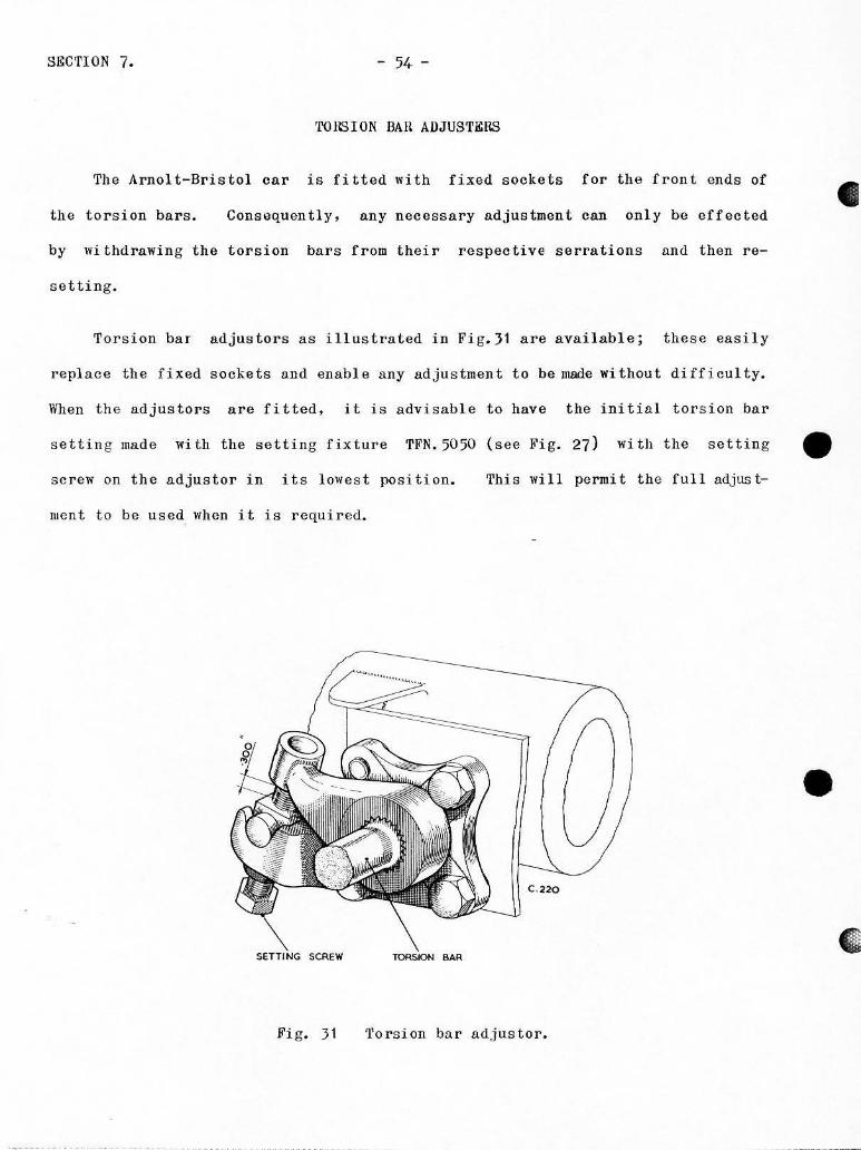
'fOlGION BAil ADJUSTERS
The Arnolt-Bristol car is fitted with fixed sockets for the front ends of
the torsion bars. Cons~quently, any necessary adjustment can only be effected
by wi thdrnwing the torsion bars from their respective serrations llnd then re
setting.
Torsion bar adjustors as illustrated in Fig.}1 are available; thes e easily
replace the fiXed sockets and enable any adjustment to be made without difficulty.
When the adjustors are fitted . it i s advisable to have the initia l tors ion bar
settin g made with the setting fixture TFN.5050 (see Fig. 27) wi th t he setting _
sc rew on the adjustor in it s lowes t position.
lIIont to be used when it i s required.
'" ,,'.G SCREW ''''
Thi s wi 11 perroi t the full adjus t -
C.220
Fi g. 31 'l'orsi on bar lldjustor.
•
•

- 55 - ggCTION 7.
SPKCIAL TOOLS
•
• (

(
•
• (
- 57 - SECTION 7 •
J /1
. r 0, . " ,,- l • RA\ mT"" iz"
j ' Il .. RAO."
-- ---
" •
" 0"
/;OIA.P IN RIYE TED OYER (GOOD HINGE fIT)
-toY lD
. I RAO
:t' ~ ,
f RAO. , , ,
r=_r---,,-------i+, h. ~-:J-
r OFf M S. C.509
TURN UP TOOL FOR TABWASHERS T.F. N.502 4 .
+------~ --f{(--',,*f--~ ~-- ---14
\: ,,-
mo/RiPI- I OFF 1.4 .5.
SPANNER FOR RETAINING RING S T. F. N. S022 .
IOFF M S.
SPA NNER FOR RETA INING NUTS T. F.N . 5023. (REAR HUBS )
:I i ~.
c==rr C . 50 9
' . 0,

SECTION 7. - 58 -
5·
5
5 ·
,"
5 HOLES .)-~· 01 .. . ORI LL ON
.o4 ·050~DIA P.C .. 4 HOLES EQUALLY SPACED AS FO~ 5 AND I !-lOLE AT 4 5' A 5 SHO WN
""".""'W M.S. LOCATING PEGS .
.!lW':m:"'Fr __ L'GHTLY RIVET O N l BACI( FAC E •
...-~ 3~_
3 .. =--1
-
PAIIT N. 721018 TO LOCAT E FREELY IN BORE & ON PEGS .
VICE PLATE FOR BEARING HOUSING . TFN. 5052
I' /;~.
TO SUIT >f4-B.S. F. NUT
" ' -200 ACADSS Fl ... TS . "j M.S. RIIO IUS EDGES. / WELO
1, -- , ,. I ---'ItOEPTI-I
I · ' OF I-IEI ,..........l- CAss/r
~!'I ' C/WRE ,.,." I 2·""_5. SAR
" SPANNER FOR NUT ON DRI VING PINIC:IN. TfN.5054 .
•
•
•
, I ,
• c
- 59 - SECTION 7,
2t/.~ OIA. HOLE
---.- ,'-_. __ ._-
4 HOL ES .".~ RE .... .., ON 3'1.~ P.C.O. TO SUIT COMPANION FLANGE.
LIGHTLY RIVET OVER ""- '-1.5. (lAP.. RADIUS EDGES. IJt I rr;.: ; "------------------------",.~'------------------~~c_-" ~L ~M
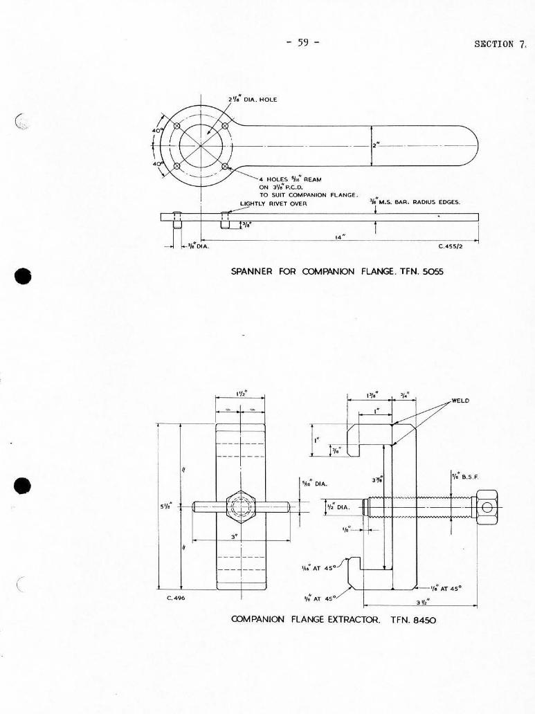
SPANNER FOR COMPANION FLANGE. TFN. 5055
l'f " , .'/ .. 'I: WELD - -
"
" 0 ---~------- ---
" 3'/: "/: S .S.F. .A. ,~;
1/2" DIA . ~ "0 5" ," -- -tt , - --1 -d "'; ?' ,,' " •
===~==== . '/L'
C. 496 I • , . , " COM PANION FLANGE EXTRACTOR TFN. 8450

SECTION 7. - 60 -
l' 'I" [
I· A"I," "
VICE FI XTURE FOR CROWN WHEEL
, . " t as.S.F SETSCREW r 1 2 LONG~
E RECESS ! fO IA f DEEP ;==
\ , --:: , ::
2 HOLES "I"~ OIA.
-- -- -Il1l±l ,"
SJ,taolT I"LONG & NUT.
2 OFF
__ ·I,.~ M.S. PLATE..
LEAVE 500FT.
,,.u)f.'/," 1.4.5 . BAR .
WEL DED ON TOP EDG£.
C.454
MOUNTING. TFN. 5056 .
CHAMFER .' . i T 45
II • • , ~= =~ / /
I't~IA ~ - ----
G .' ,~ .' I t
I 1>, DI ", ,
I .' ff ·0_0
• !of I I I 2t~
" ,"
," c ,
0 r - - - , - " , , , , I ,
, , , I I I , It I , I
, I , " I
, , I , I I
, , I I I I , I , , , _J ___ ~ _ '- __ _ L __ ..... L
M .5. SKIN HARDE N
EXTRACTOR- ROlLER RACE FROM CROWN WHEEL MOUNTING.
TFN .5057. C.502
•
• c

c
•
•
- 61 -
10 CUT- OUTS . FI LE TO SUIT PINION N. 4902.21.
--~'\" '",",".--.~
MAKE FROM GOOD CASEHAAOENING STEEL AND CASEHAADEN
J~ OIA.
--I ,·.1 I •
C.460/2.
PLATE FOR REMOVING ROLLER RACE FRONt DRIVING PINION . TFN . 5058 .
-_._. - _.- - -
,. 3 l OI A. 101 .5. BAR
C. 460/1.
SUPPORT RING FOR PRESSING THE ROLLER RACE FROM THE PINION. TFN. 5059.
g8CTION 7.

SECTION 7, - 62 -
, ...
" "
MS. BAR .
, , 1 ,
1/ '\ .. " "
" " " ~
1"- ~ i ,"
C . 8011
SPIGOT FOR REMOVING OUTER ROLLER RACE ,( LARGE) T.F,N.S0 61.
RING FOR PRESSING OUT PDLLER BEARING. T.F.N.S062.
" 2ii DIA.
I 1
I;; 1 ~
1
\ 1"- / V 1'- ./
I . • I
",."o"- i IE! =::=:::::JJi I "
'I F.N .!ObO
M S. BA R
1.'
5 PIGOT AND RING F OR REMOVING OUTER ROLLER RACE ,(SMALL.)
I' I
C 480 12
((
•
• (

c
•
•
- 6J -
"
---------------- I , , , , , . . , , , , ---- ----- - , ,
PORTION OF HALF SHAFT
'I. ~ 04.\ . ~ . s. & ... 11.
KEY FOR [){FFERENTIAL BEVEL GEARS. TFN. 5064.
TWO FLAT!'. FOR. VICE GRIP. I Y. ACROSS fLATS
7/1~
- IX I~:
C . ... 59
2'1,b OIA M S BAR
,. . ',"0' I _Q68w
1·374DiA . " '76 01.1. . ' -062 OIA.
" " " L , '.
DUMMY DRIVING PINION . TFN.5063
SECTION 7.
,.'
,
r 'I: 8 .S .F .
. , 1:491/2

SECTION 7. - 64 -
1---+------. 014. ~_s. e 4 R .
I 104.5. eAR
• 51.0T5
IIIII \. C "14
3' LONG
__ --;." ••• 0 LENGTH
~' ORILL ~'O'''''-H DRILL h" 0 1... . I ,~ " "" "". - 1;JL.L\I.'" ;"iw
I~ 'r."RAD I·:JOC)·OOO
i •. ,., =tP~' -'OO' 1 tOO TAPER • I
1/;014
HANDLE FOR CROWN WHEEL MOUNTING. TFN. 5066 .
REMOVE SHARP EDGE WITH FILE TO CONFO RM TO OIMEN SIO H M ARKEO THUS ·
"
" J.i 0 A.
LlI.>.f.-t--t-
" ,.
I OFF H.1:S.
" STANOARD i BS_f. HEXAGON HEAD
I OFF 11 ," "".5. -..f.+..i-" I
" ; ,,' .. " i K 4 5· CHAMFER
" 2 i OIA.
, i OlA.. " ii x 4 5' CHAM FER
~.. . u )( 60 IHCLUOEO ANGLE
C.SIO
REAR SUSPENSION ARM EXTRACTOR T.EN. 8039.
•
• (
• HARDEN
I OFF II .S.F.
• C.5 13
c
S.S . PI N I OFF.
- 65 -
0/0 X 111 S .W.G. M.S.
k OlA
I OFF MS.
JlI'l,-1";,,',,' REF. ONLY
SLIDE FIT
· .,'" -,++~t • .1" · .
1<.15. TUS"''-_ -/.'f:i 2 OFF -
, OFF.
RUNNING FIT
I orF
M.S. PIN 2 OFF.
SPRING TO SUIT
,
SECTI ON 7.
> • < • ~
" ,
o • -• o Z < , o
, 0
I OFF OURAL
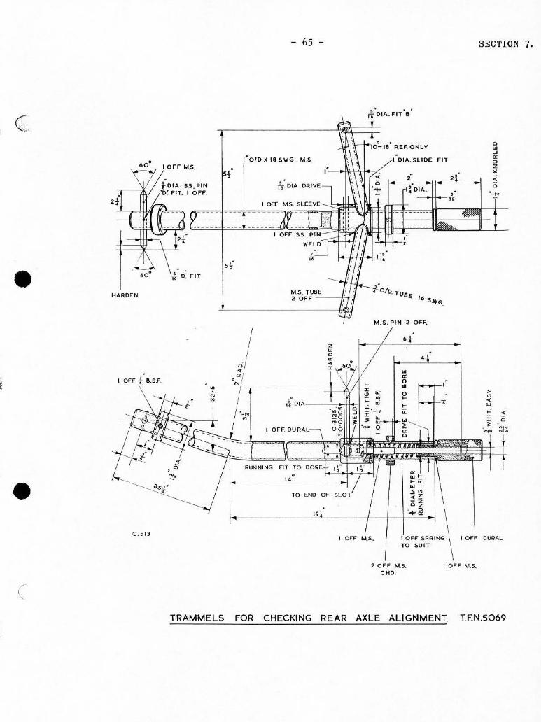
TRAMMELS FOR CHECKING REAR AXLE ALIGNMENT. T.F.N.5069
SECTION 7.
I •
- 66 -
.
2'1.~ M I-'-= 0/
DRILL 111u" DI •.
CSK. TOf' FACE " •• AT 4S?
c .503
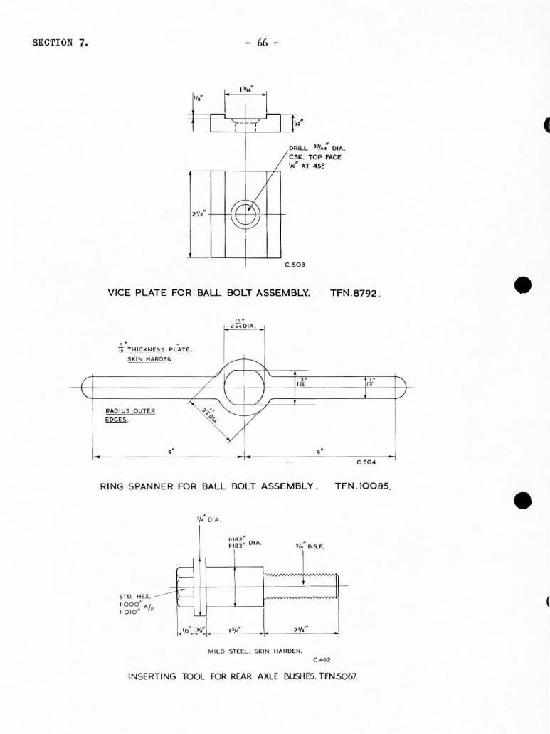
VICE PLATE FOR BALL BOLT ASSEMBLY. TFN .B792 .
,,'
,. C'1 iO THICKNESS PLATE .
SKIN H ... ROEN.
--,-" ~f - I~
RADIUS OUTER J':,
EDGES. '0 •
, . -I. " C.S04 -I
RING SPANNER FOR BALL BOLT ASSEMBLY . TFN . I008S.
---'" st~. HE., . -000" A/ 1.010. F
~~ )-
f=:: ~
,t ){.~
,,: 6.5 F ..
1 1~· 1 2'1.'
M ILD STEEL SKIN HARDEN.
INSERTING TOOL FOR REAR AXLE BUSHES. TFN.50b7.
•
• (

•
• (
- 67 -
, ,
't. ~ S.S.F. THIN NUT
,
I i--r~ , , , l<:- :----, . ' ,
SECTION 7.
REAM ":OIA. FI T ' 6 : Sf FACE "I,: OIA . i r 'f: C HAMFER AT 45° r
C;;;~;;~~::·~·~·:::·~·~·~·1'~~iC~·]±!'A/F- ~~.M 01" _~_ RIGHT HAND CUT TING 6 BLADES I ~~~ •. - .. TO CUT PHOSPHER BRONZ E -oooJ" - - -- ----.,. - r -'-
C . 482
I .. '// ",' OIA. F IT '6' &ORE RIGHT THROUGH
" o I OFF. H S.S. HARDEN AND GRIND
.' i I
.. L .. I t r i .
" "
'. L~E ",o'OIA.
o I OFF. 1.1 .5.
REAM ER FOR REAR AXLE BUSHES.
1,/ • OIA " ,
I~ i r , / 1
I , I
I
4 ·1. ~
'I: 0'''' , FIT '~
w
r IV" 1'1,· ~ ~
2 ',: GRI " THIS OVER LENGT "
'h: j-,. /' L_ l o,,: oIA.
DRI LL "/nOIA. FOR TOMMY BAI'< o I OFF. H.T.S .
, ,'/.:,1 i rt";· tr- ::~ 'I' ~- e-
" " , ;-[ ~ 01 ... . FIT Z . ~. SS F.
I O FF. US AS. C ASE HARO€N AND GRIND L EAVE TH RE AOS SOFT
TFN. 4662 .

SECTION 7. - 68 -
2'!1 ·S' TA,UE SETTING.
14 '.% '
El) d .~ &.
j "
11 0
• " 0
-'l: \ ». 0 :0 0
" " '0 • 8 ,
•
" ITEM O€SCRIPTIO N ;~ MATERIALS "'" DESCRIPTION
0" MATER IALS , PLATE , M.S. ~~':' ", ' ,. LOCATION PLATE M' •• CAP SCREW . , , • S.S. f . X 2 LONG
,. DOWEL , SILVER STEEL '0 . PLATE , 1..1 . 5 . ~ 01.11.. X L\' LONG. ". CHAIN . , SRA SS . TO SU IT.
STD. UNBRAKO. " PIN . , SI LVER STEEl. 0 1,1, . ,. C'" SCREW , ~a.s. F. X 1 ~'lONG . ". DISTANCE PIECE , M .S .
S c<P SCREW. , "" UNBRAKO. ~ .. 6 .S.F. X ~·LONG. ... SET SCREW . , M . S.
~ '8 . S. F. X ~'LON G
SILVER STEEL . " WASHE R 0 1.11. . , M . S. STOCK • DOWEl. , ~D IA . X ~·LONG . ST O. UNBRAKO.
" CAP SCREW. , '/ "8 S.F. X~iONG , SETTING PLLLAR , M .S.
8 SLIDE. , M. S. " DISC , M'. S.
THI S PORTI ON TO BE A GOOD SLIDE F IT IN ITEM .B.
2 HOLES - REAM TO SU IT ~'SI LVER STEEL DOWEL (UGHT
2 HOLES, DRI LL LETTER'O'AND C/aORE '). DEEP TO SUIT 'V~
_ ,, ' DRIVE Fll l .SPOT FROM DET. 7 I ~" CAP SCREWS .. " (SEE G. A)~
. r4-If..----f-l ~~~-------=1 . .t,~ ,, ~ -!j \-
~
4 '!s.' SLOT
C . 470/1.
-, 2 HOlES - TAP ~':6 . S. F SPOT FROM DET. 7 ( 5£E G. A.)
2 I-fOLES- RE AM TO SU I T s~ SILVER STEEL DOWEL (LIGHT
DRIVE FIl)
"~~~~' I' , 01
. ~ HOLE'.!(..DIA .~
LI%'ol,J TORSION BAR SETTING JIG . TFN. 5050.
, :
€:
•
• (

c
•
•
- 69 - SECTION 7.
2 HOLES -DRILL LSTTER'O "ANO C/8ORE
~'OEEP TO SUIT7;;CAP SCREWS 2 HOLE5- T ... p7;~8 , S_F. SPOT
FROM OET. 7. (SEE G,".) 2 HOLES-ORI LL LETTER '0' AND C/BORE
Y.-OEEP TO SU IT ~':CAP SCREWS
.. -'
~~o ~~~ ________ -+~ .V ~ ~~ %" I !..;."CTS. 2 HOLES-REAM TO SUITY';
.:!-l-+-I.--l---"'-'-'" SILVER STEEL DOWEL (LIGHT 2 HOLES- REAM TO SUIT~6· SILVER STEEL DOWEL (LIGHT
DRIVE FIT) . SPOT FROM DET. 7.(5££ G."')
ORIVE FIT) . :''1 GOOD FIT
@ 'If.--':· __ ,I· _ _ ~". __ -j __ +_'I:1
TO BE A I N ITEM . 8 .
t HOLE - BORE
2 HOL£5- REA M TO SUIT '7" • .SILVER STEEL OOWEL(UGHT DRIVE FIT) IN POSITION
,m G.) '"0:. "'j' "" '0 r-~ r
"-----L----c/c--------"-,<+"----1 2 HOLES - REAM lo(';OIA _IN 2 HOLES- TAP~":B. S_F iN POSITION
POSITION (S EE G . ... . ) (SEE G,II.) FROM OETS. I . AND 10
j==·p\r'L :\: ==*: ==*"1: ::::rp::: ,.
1-265+ 005
\ I"RAD.
I
:2 HOlES- DR ILL THROUGH AND
C/BORE Y,DEEP TO SUIT'!{."OIA..
CAP SCREWS
2 HOLES- TAPli< 6.S.F.
SPOT FROM OET. 10. I HOLE - TAP~·(e . S . F
.,,~ wo " ,
, "
I HOLE - TAP 7;:B_S,F
/
2 HOLES-REAM TO SUIT r';SILVER STEEL DOWEL
(LIGHT DRIVE FI T.)
2 HOLES - REAM TO SLlIT
r,;SILVER STEEL DOWEL
(LI GHT DRIVE FIT) IN -ItJ :~[ ~ / PO"o:o, .~",~:,;~
, . ~ II~ ~ , "OU,S-,,'" CH"" 00-~- SLOT TO SUIT? IN POSITION WITH
L.----,----,- -----,.1 ill ITEMS .I.ANO 10 OET 7. AND I.OR 10 .
C.470/2.
COM PONENTS FOR TORSION BAR SETTING JIG. TFN.SOSO.

S&CTION 7.
STOCK H.T.S. WASHER & NUT
DRILL f ol ... .
- 70 -
I O FF H . T.5
TORSION BAR EXTRACTOR T. F N. 5026
EJECTOR
LEAD ON TI-1RE.o.O
C.SIL
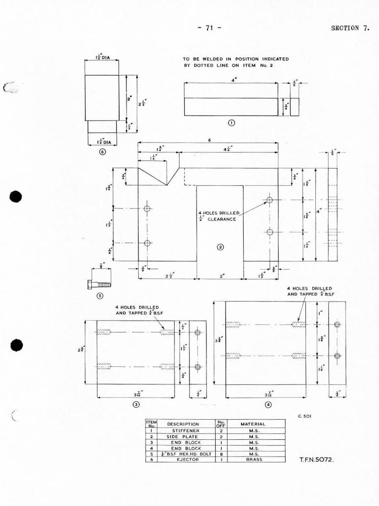
CARRIER FOR REAR SUSPENSION UNIT. T.F.N.S072 .
•
• c
c
•
• , r
, of
, ot
, , -
Q , ®
" 0-.' 0-
tj ~ 11 I- - +-
•
I 1- -. rt
- t'L ,t'
... HOLES DR ILLED AND TAPPED t-asF
- 71 -
TO BE WE LDED IN POSITION INDICATED
BY DOTTED LINE O N ITE M No. 2
CD
, .' .-, .' ,
-• ... " .-V 4 HOLES Df'I;ILL~O ....
·F CLE ARANCE I
'" -T
®
-;- t"f-,- ot
SgCTION 7,
- i~
It" "
-- , l'::' " -- ,
If • ,.
F "
" --0_ .,'
"HOLES DR.ILI"ED AND TAPPED f as.F
.-'::..,:.~::;. . ~L f -. -- . -------<:;..,:.. ) .w ~ t-
~ F-~ -_. I--,' --'--.'~;::;:;:
,l' It - I It I I--t - k""'--' - ' ~-::;, .-I-
~ -~ ~-
... ,,'w, -:.:" ,-.. :;;.,. ..... -- , -- '-',,' ~
o-f
3;1 N 1.£ 3 ;'0- w::.. ®
C .501
I01~ DESCR I P T ION ~,; MATERIAL
0 STIFFENER , M.S· , SI DE PLATE , 1.4 .5 . , '"" BLOCK 0 1.1 .5.
4 '"' BLOCK 0 1.4 .$. , B.SF HEX. HO. BOLT • M.S. , EJECTOR 0 eA ... ss TFN.S072 .

SECTI ON 7.
"
, . .. ,, ' " ,
3"'ii JIi
- 72 -
, "
" ..
,, ' 2; HOLES - >i 01,1. .
-j--I'lffi§<::
" . .. BOLT- r LONG
AND NUT (2 OFF)
" " .. "' .S PLATE LEAVE SOFT
3 - I ·
. >< "'i M .S BAR WELOEO ON TOP EDGE.
c.""
VICE FIXTURE FOR DIFFERENTIAL ASSEMBLY. TFN .s053
c
•
• (

•
•
- 7J -
I 11111111 11 III 1111
DESCRIPTION No. 0", MATERIAL
TOMMY aAR-TOSUfT MILD STEEL
2 DRAW BOLT MILD STEEL
1 END PLATE MILD STEEL
4 TIE RODS 2 MILD STEEL
EXTRACTOR FOR t~'~~C~U~"~'~"-~A~T~'=~i~~M~'CO~~,,~,~a~ MAl N SHAFT ARM . (, ~ESS BLOCK MILD STEEL
(REAR INNER NEEDLE ti'~~C~'~AM~'~~~~~~~M~"~O~,,;,~,~,j ROLLER RAC E .) T. F. N 5070 I-:;'-+~""'-~"~"-:;"~V~'",-+--.:'-+:M~":O=--"~':':'-+
9 2 EtA SET SCREW TO SUIT
TO SUIT
,. 10 4" 8 .S-F BOLT , TO SUIT
I I "I"S.S.F NUT (, MILD STEEL
SECTION 7.

SECTION 7. - 74 -
~ EEEF===~, . ===~~;,~=3""
.----------------~" ----------------~~
, : , i I1
, ,
" , , , : • , , , , :
, . ' ''-
" " ( ~ ( y "",) D
, ,
TOMt.lV ft.AR " 'HO"'f.·"./ cl
TO SUIT
-
r-. " "
-
, . ••
/ WELO ----. __ .. '.---
, " fJ
,
- Jr-
, . lli
li ,
r-
~f " ,.
~. ,
•
" 1" RAo,
!!"orA. "
" "
,
, . ,. ii OIA
" 4" 01".
,
"
~. ,
'ii RAO.
,. I»RAO.
" .. O lA . a-S.f l
,. , .
EXTRACTOR FOR MAI N SHAFT ARM. (REAR INNER NEEDLE ROLLER RACE)n:NS070
•
• <

•
•
- 75 -
~.
2 !ilLOT!. APAOX ,{ WIDE. j" LONG
M.lKE TO SUIT PART N.490271
LOCKING RING
f M S. PLATE . !>K IN H.o.ROEN
RADIUS THESE EDGES I-----'.--' FOI>. GAIP
C 46J .
SPANNER FOR LOCKING RING. TFN.5065 .
SECTION 7.