alu - a7302 isam fttu operator gpon nant-e_ce-pdf
DESCRIPTION
Operator Gpon fttxTRANSCRIPT
7/18/2019 Alu - A7302 Isam Fttu Operator Gpon Nant-e_ce-PDF
http://slidepdf.com/reader/full/alu-a7302-isam-fttu-operator-gpon-nant-ece-pdf 1/432
© 2010 Alcatel-Lucent, All Rights ReservedISAM Product Overview Intro and Architecture 1
ALU ISAM - product overview
Introduction
During class please switch off your mobile, pager or other that may interrupt.

7/18/2019 Alu - A7302 Isam Fttu Operator Gpon Nant-e_ce-PDF
http://slidepdf.com/reader/full/alu-a7302-isam-fttu-operator-gpon-nant-ece-pdf 2/432
© 2010 Alcatel-Lucent, All Rights ReservedISAM Product Overview Intro and Architecture 2
2
Objective
Upon completion of the module you will be able to
explain why we need the ISAM
• What is the ISAM and why do we need it?
7/18/2019 Alu - A7302 Isam Fttu Operator Gpon Nant-e_ce-PDF
http://slidepdf.com/reader/full/alu-a7302-isam-fttu-operator-gpon-nant-ece-pdf 3/432
© 2010 Alcatel-Lucent, All Rights ReservedISAM Product Overview Intro and Architecture 3
3
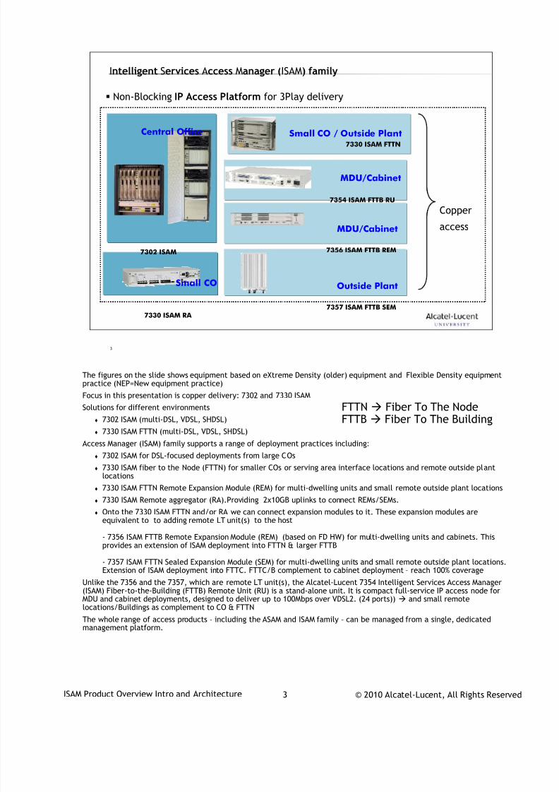
Intelligent Services Access Manager (ISAM) family
Non-Blocking IP Access Platform for 3Play delivery
Central Office
7302 ISAM
Small CO / Outside Plant7330 ISAM FTTN
MDU/Cabinet
7356 ISAM FTTB REM
Copper
access
Outside Plant
7357 ISAM FTTB SEM
7354 ISAM FTTB RU
MDU/Cabinet
7330 ISAM RA
Small CO
The figures on the slide shows equipment based on eXtreme Density (older) equipment and Flexible Density equipment
practice (NEP=New equipment practice)Focus in this presentation is copper delivery: 7302 and 7330 ISAM
Solutions for different environments
7302 ISAM (multi-DSL, VDSL, SHDSL)
7330 ISAM FTTN (multi-DSL, VDSL, SHDSL)
Access Manager (ISAM) family supports a range of deployment practices including:
7302 ISAM for DSL-focused deployments from large COs
7330 ISAM fiber to the Node (FTTN) for smaller COs or serving area interface locations and remote outside plantlocations
7330 ISAM FTTN Remote Expansion Module (REM) for multi-dwelling units and small remote outside plant locations
7330 ISAM Remote aggregator (RA).Providing 2x10GB uplinks to connect REMs/SEMs.
Onto the 7330 ISAM FTTN and/or RA we can connect expansion modules to it. These expansion modules areequivalent to to adding remote LT unit(s) to the host
- 7356 ISAM FTTB Remote Expansion Module (REM) (based on FD HW) for multi-dwelling units and cabinets. Thisprovides an extension of ISAM deployment into FTTN & larger FTTB
- 7357 ISAM FTTN Sealed Expansion Module (SEM) for multi-dwelling units and small remote outside plant locations.Extension of ISAM deployment into FTTC. FTTC/B complement to cabinet deployment – reach 100% coverage
Unlike the 7356 and the 7357, which are remote LT unit(s), the Alcatel-Lucent 7354 Intelligent Services Access Manager(ISAM) Fiber-to-the-Building (FTTB) Remote Unit (RU) is a stand-alone unit. It is compact full-service IP access node forMDU and cabinet deployments, designed to deliver up to 100Mbps over VDSL2. (24 ports)) and small remotelocations/Buildings as complement to CO & FTTN
The whole range of access products – including the ASAM and ISAM family – can be managed from a single, dedicatedmanagement platform.
FTTN Fiber To The NodeFTTB Fiber To The Building
7/18/2019 Alu - A7302 Isam Fttu Operator Gpon Nant-e_ce-PDF
http://slidepdf.com/reader/full/alu-a7302-isam-fttu-operator-gpon-nant-ece-pdf 4/432
© 2010 Alcatel-Lucent, All Rights ReservedISAM Product Overview Intro and Architecture 4
4
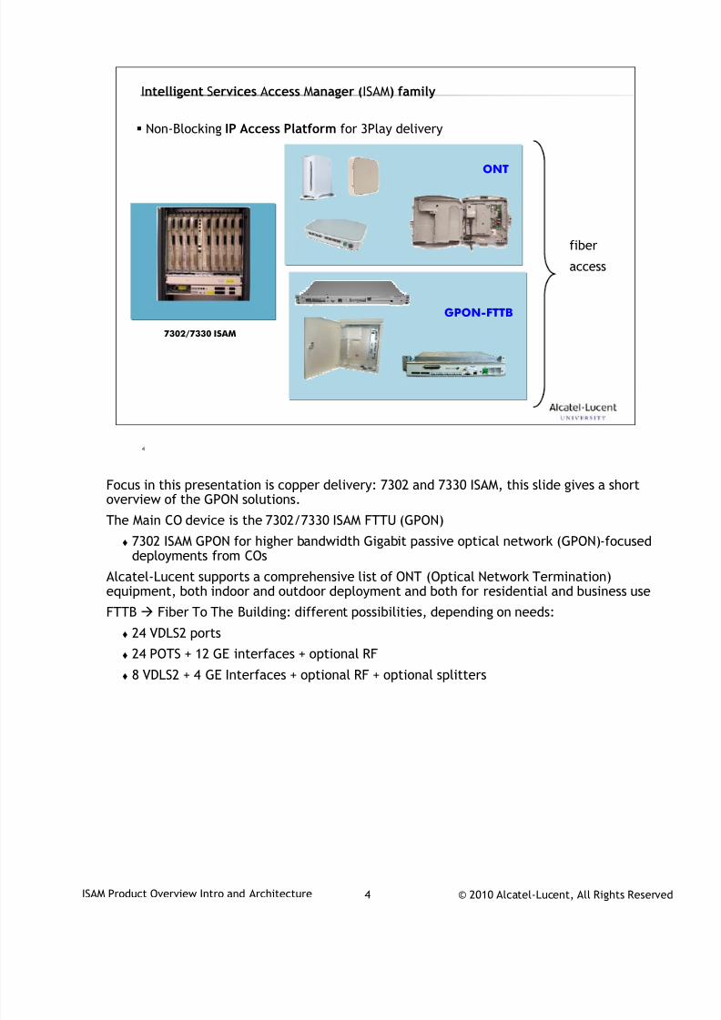
Intelligent Services Access Manager (ISAM) family
Non-Blocking IP Access Platform for 3Play delivery
fiber
access
ONT
GPON-FTTB
7302/7330 ISAM
Focus in this presentation is copper delivery: 7302 and 7330 ISAM, this slide gives a short
overview of the GPON solutions.
The Main CO device is the 7302/7330 ISAM FTTU (GPON)
7302 ISAM GPON for higher bandwidth Gigabit passive optical network (GPON)-focuseddeployments from COs
Alcatel-Lucent supports a comprehensive list of ONT (Optical Network Termination)equipment, both indoor and outdoor deployment and both for residential and business use
FTTB Fiber To The Building: different possibilities, depending on needs:
24 VDLS2 ports
24 POTS + 12 GE interfaces + optional RF
8 VDLS2 + 4 GE Interfaces + optional RF + optional splitters
7/18/2019 Alu - A7302 Isam Fttu Operator Gpon Nant-e_ce-PDF
http://slidepdf.com/reader/full/alu-a7302-isam-fttu-operator-gpon-nant-ece-pdf 5/432
© 2010 Alcatel-Lucent, All Rights ReservedISAM Product Overview Intro and Architecture 5
5
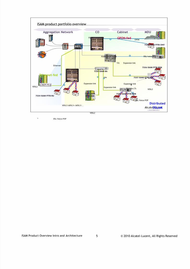
ISAM product portfolio overview
Internet
7450 ESS7750 SR
IPTV
VoIP7302 ISAM FTTU
7330 ISAM FTTN
VDSL2
GPON
DSL/Voice/P2P
7357 ISAMFTTB SEM
7352 ISAM FTTB ONT
7356 ISAM FTTB REM
7354 ISAM FTTB RU
DSL/voice/P2P
Expansion link
Ethernet
7330 ISAM RA
Expansion link
7357 ISAM FTTB SEM
Expansion link
Expansion link
7356 ISAM FTTB REM
VDSL2
VDSL2
VDSL2
Ethernet-fed
GPON-fed
Distributed
DSLAM
12x
24x
Remote LTs
CO Cabinet MDUAggregation Network
VDSL2/ADSL2+/ADSL2/…
7302 ISAM
DSL/Voice/P2P
7/18/2019 Alu - A7302 Isam Fttu Operator Gpon Nant-e_ce-PDF
http://slidepdf.com/reader/full/alu-a7302-isam-fttu-operator-gpon-nant-ece-pdf 6/432
© 2010 Alcatel-Lucent, All Rights ReservedISAM Product Overview Intro and Architecture 6
6
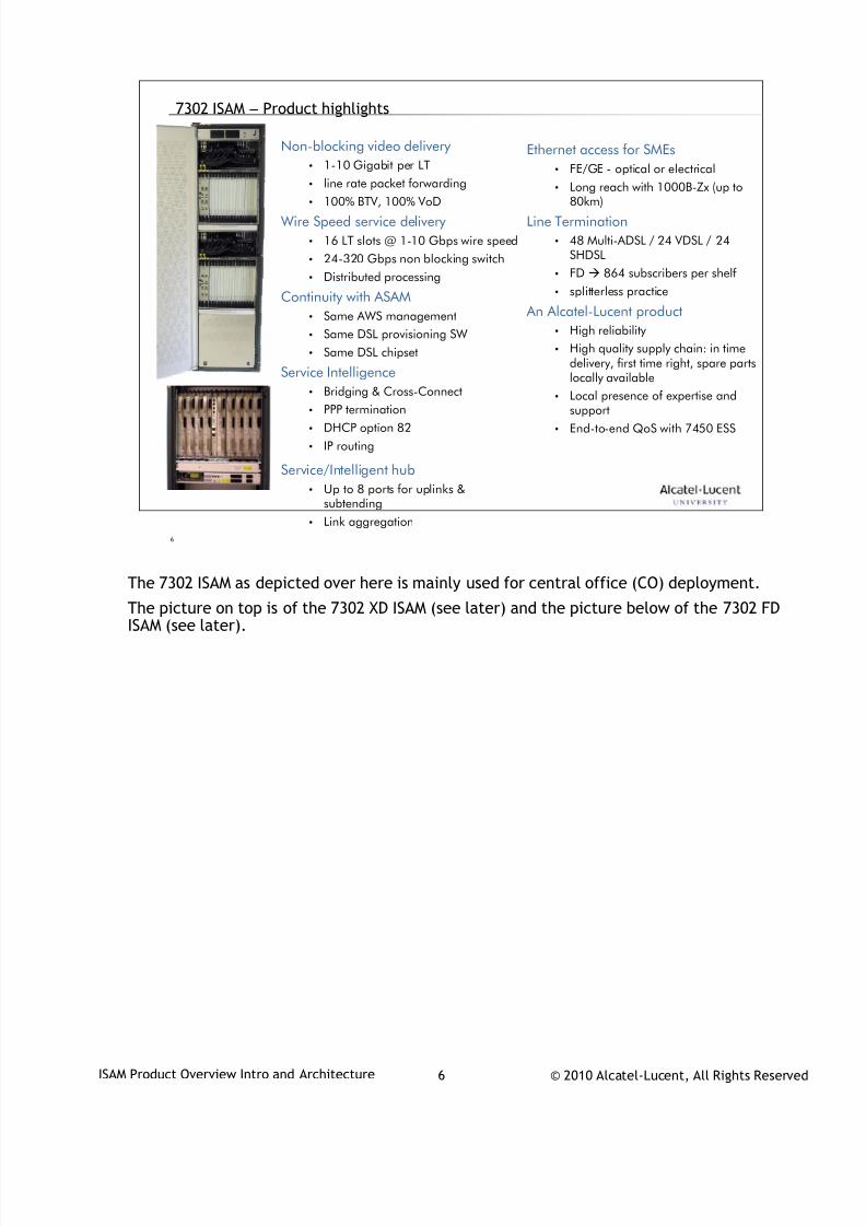
Ethernet access for SMEs
• FE/GE - optical or electrical
• Long reach with 1000B-Zx (up to
80km)
Line Termination
• 48 Multi-ADSL / 24 VDSL / 24SHDSL
• FD 864 subscribers per shelf
• splitterless practice
An Alcatel-Lucent product
• High reliability
• High quality supply chain: in timedelivery, first time right, spare partslocally available
• Local presence of expertise andsupport
• End-to-end QoS with 7450 ESS
7302 ISAM – Product highlights
Non-blocking video delivery
• 1-10 Gigabit per LT
• line rate packet forwarding
• 100% BTV, 100% VoD
Wire Speed service delivery
• 16 LT slots @ 1-10 Gbps wire speed
• 24-320 Gbps non blocking switch
• Distributed processing
Continuity with ASAM
• Same AWS management
• Same DSL provisioning SW
• Same DSL chipset
Service Intelligence
• Bridging & Cross-Connect
• PPP termination
• DHCP option 82
• IP routing
Service/Intelligent hub
• Up to 8 ports for uplinks &subtending
• Link aggregation
The 7302 ISAM as depicted over here is mainly used for central office (CO) deployment.
The picture on top is of the 7302 XD ISAM (see later) and the picture below of the 7302 FDISAM (see later).
7/18/2019 Alu - A7302 Isam Fttu Operator Gpon Nant-e_ce-PDF
http://slidepdf.com/reader/full/alu-a7302-isam-fttu-operator-gpon-nant-ece-pdf 7/432
© 2010 Alcatel-Lucent, All Rights ReservedISAM Product Overview Intro and Architecture 7
7
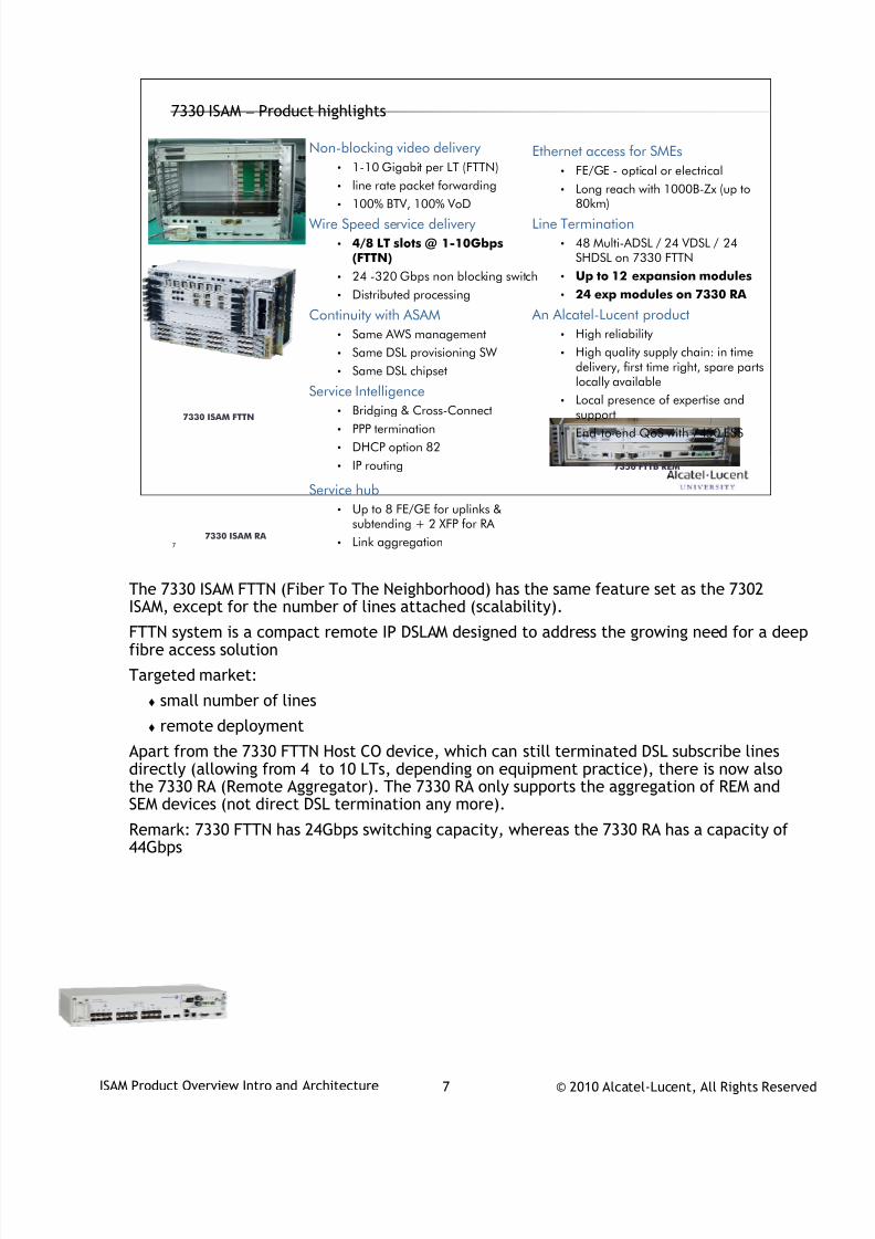
7330 ISAM – Product highlights
Ethernet access for SMEs
• FE/GE - optical or electrical
• Long reach with 1000B-Zx (up to
80km)
Line Termination
• 48 Multi-ADSL / 24 VDSL / 24SHDSL on 7330 FTTN
• Up to 12 expansion modules
• 24 exp modules on 7330 RA
An Alcatel-Lucent product
• High reliability
• High quality supply chain: in timedelivery, first time right, spare partslocally available
• Local presence of expertise andsupport
• End-to-end QoS with 7450 ESS
Non-blocking video delivery
• 1-10 Gigabit per LT (FTTN)
• line rate packet forwarding
• 100% BTV, 100% VoD
Wire Speed service delivery
• 4/8 LT slots @ 1-10Gbps(FTTN)
• 24 -320 Gbps non blocking switch
• Distributed processing
Continuity with ASAM
• Same AWS management
• Same DSL provisioning SW
• Same DSL chipset
Service Intelligence
• Bridging & Cross-Connect
• PPP termination
• DHCP option 82
• IP routing
Service hub
• Up to 8 FE/GE for uplinks &subtending + 2 XFP for RA
• Link aggregation
7330 ISAM FTTN
7330 ISAM RA
7356 FTTB REM
The 7330 ISAM FTTN (Fiber To The Neighborhood) has the same feature set as the 7302
ISAM, except for the number of lines attached (scalability).
FTTN system is a compact remote IP DSLAM designed to address the growing need for a deepfibre access solution
Targeted market:
small number of lines
remote deployment
Apart from the 7330 FTTN Host CO device, which can still terminated DSL subscribe linesdirectly (allowing from 4 to 10 LTs, depending on equipment practice), there is now alsothe 7330 RA (Remote Aggregator). The 7330 RA only supports the aggregation of REM and
SEM devices (not direct DSL termination any more).Remark: 7330 FTTN has 24Gbps switching capacity, whereas the 7330 RA has a capacity of44Gbps
7/18/2019 Alu - A7302 Isam Fttu Operator Gpon Nant-e_ce-PDF
http://slidepdf.com/reader/full/alu-a7302-isam-fttu-operator-gpon-nant-ece-pdf 8/432
© 2010 Alcatel-Lucent, All Rights ReservedISAM Product Overview Intro and Architecture 8
8
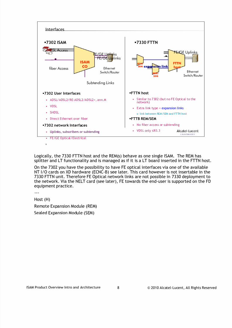
Interfaces
7302 User Interfaces
• ADSL/ADSL2/RE-ADSL2/ADSL2+, ann.M
• VDSL
• SHDSL
• Direct Ethernet over fiber
7302 network Interfaces
• Uplinks, subscribers or subtending
• FE/GE Optical/Electrical
FTTN host
• Similar to 7302 (but no FE Optical to thenetwork)
• Extra link type = expansion links
o link between REM/SEM and FTTN host
FTTB REM/SEM
• No fiber access or subtending
• VDSL only ≤R3.3
ISAMCO
DSL Access
fiber Access
Subtending Links
FE/GE Uplinks
EthernetSwitch/Router
7302 ISAM 7330 FTTN
FTTNhost
REM/SEM
REM/SEM expansion link
EthernetSwitch/Router
FE/GE UplinksFE/GE Uplinks
Logically, the 7330 FTTN host and the REM(s) behave as one single ISAM. The REM has
splitter and LT functionality and is managed as if it is a LT board inserted in the FTTN host.
On the 7302 you have the possibility to have FE optical interfaces via one of the availableNT I/O cards on XD hardware (ECNC-B) see later. This card however is not insertable in the7330 FTTN unit. Therefore FE Optical network links are not possible in 7330 deployment tothe network. Via the NELT card (see later), FE towards the end-user is supported on the FDequipment practice.
---
Host (H)
Remote Expansion Module (REM)
Sealed Expansion Module (SEM)

7/18/2019 Alu - A7302 Isam Fttu Operator Gpon Nant-e_ce-PDF
http://slidepdf.com/reader/full/alu-a7302-isam-fttu-operator-gpon-nant-ece-pdf 9/432
© 2010 Alcatel-Lucent, All Rights ReservedISAM Product Overview Intro and Architecture 9
9
www.alcatel-lucent.comwww.alcatel-lucent.com
7/18/2019 Alu - A7302 Isam Fttu Operator Gpon Nant-e_ce-PDF
http://slidepdf.com/reader/full/alu-a7302-isam-fttu-operator-gpon-nant-ece-pdf 10/432
© 2010 Alcatel-Lucent, All Rights ReservedTAC03001-HO04 1
Alcatel-Lucent
7302-7330-735x ISAM
During class please switch off your mobile, pager or other that may interrupt.

7/18/2019 Alu - A7302 Isam Fttu Operator Gpon Nant-e_ce-PDF
http://slidepdf.com/reader/full/alu-a7302-isam-fttu-operator-gpon-nant-ece-pdf 11/432
© 2010 Alcatel-Lucent, All Rights ReservedTAC03001-HO04 2
2
Table of Contents
1. Shelf Types
2. Board Types

7/18/2019 Alu - A7302 Isam Fttu Operator Gpon Nant-e_ce-PDF
http://slidepdf.com/reader/full/alu-a7302-isam-fttu-operator-gpon-nant-ece-pdf 12/432
© 2010 Alcatel-Lucent, All Rights ReservedTAC03001-HO04 3
3
Shelf Types1
7/18/2019 Alu - A7302 Isam Fttu Operator Gpon Nant-e_ce-PDF
http://slidepdf.com/reader/full/alu-a7302-isam-fttu-operator-gpon-nant-ece-pdf 13/432
© 2010 Alcatel-Lucent, All Rights ReservedTAC03001-HO04 4
4
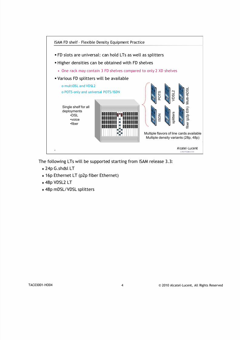
ISAM FD shelf – Flexible Density Equipment Practice
FD slots are universal: can hold LTs as well as splitters
Higher densities can be obtained with FD shelves
• One rack may contain 3 FD shelves compared to only 2 XD shelves
Various FD splitters will be available
o multiDSL and VDSL2
o POTS-only and universal POTS/ISDN
M u l t i - A D S L
V D S L 2
P O T S
I S D N
f i b e r ( p 2 p E t
h )
s p l i t t e r s
Multiple flavors of line cards available
Multiple density variants (28p, 48p)
Single shelf for all
deployments•DSL
•voice
•fiber
The following LTs will be supported starting from ISAM release 3.3:
24p G.shdsl LT
16p Ethernet LT (p2p fiber Ethernet)
48p VDSL2 LT
48p mDSL/VDSL splitters

7/18/2019 Alu - A7302 Isam Fttu Operator Gpon Nant-e_ce-PDF
http://slidepdf.com/reader/full/alu-a7302-isam-fttu-operator-gpon-nant-ece-pdf 14/432
© 2010 Alcatel-Lucent, All Rights ReservedTAC03001-HO04 5
5
Shelf types – FD equipment practice
ISAM 7302 - FD
• FD -NFXS-A
o ETSI shelf for 16/18 boards (x lines)
o universal slot concept allows any mix of xDSL LTs, splitters, fiber LTs, voice cards
ISAM 7330 FTTN - FD
• FD-NFXS-B
o Mini-RAM ETSI shelf for 8/10 boards (x lines)
o universal slot concept allows any mix of xDSL LTs, splitters, fiber LTs, voice cards
7356 FTTB REM - FD• FD-NFXR-A
o can be connected to 7330 FTTN XD or FD.
7/18/2019 Alu - A7302 Isam Fttu Operator Gpon Nant-e_ce-PDF
http://slidepdf.com/reader/full/alu-a7302-isam-fttu-operator-gpon-nant-ece-pdf 15/432
© 2010 Alcatel-Lucent, All Rights ReservedTAC03001-HO04 6
6
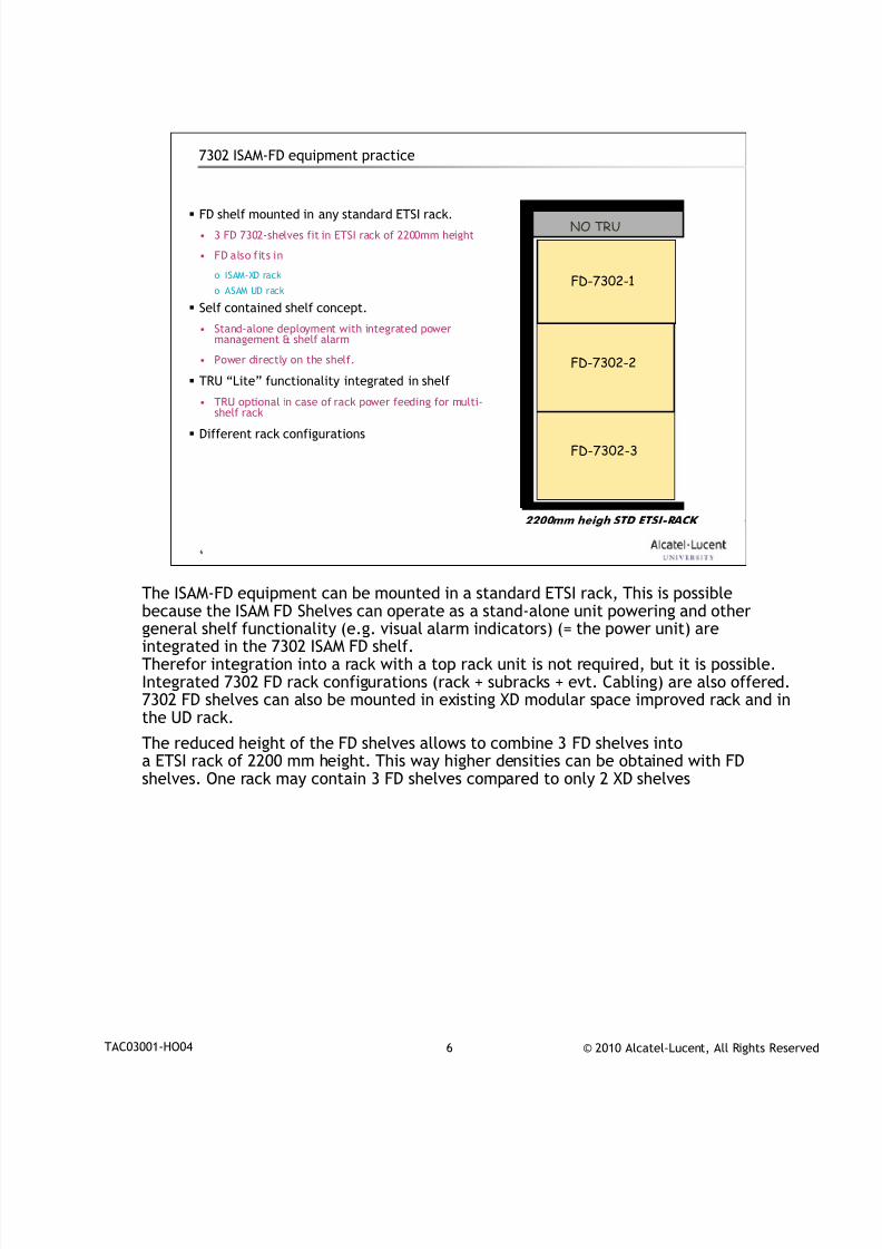
7302 ISAM-FD equipment practice
FD shelf mounted in any standard ETSI rack.
• 3 FD 7302-shelves fit in ETSI rack of 2200mm height
• FD also fits in
o ISAM-XD rack
o ASAM UD rack
Self contained shelf concept.
• Stand-alone deployment with integrated powermanagement & shelf alarm
• Power directly on the shelf.
TRU “Lite” functionality integrated in shelf
• TRU optional in case of rack power feeding for multi-shelf rack
Different rack configurations
2200mm heigh STD ETSI-RACK
NO TRU
FD-7302-2
FD-7302-1
FD-7302-3
The ISAM-FD equipment can be mounted in a standard ETSI rack, This is possible
because the ISAM FD Shelves can operate as a stand-alone unit powering and othergeneral shelf functionality (e.g. visual alarm indicators) (= the power unit) areintegrated in the 7302 ISAM FD shelf.Therefor integration into a rack with a top rack unit is not required, but it is possible.Integrated 7302 FD rack configurations (rack + subracks + evt. Cabling) are also offered.7302 FD shelves can also be mounted in existing XD modular space improved rack and inthe UD rack.
The reduced height of the FD shelves allows to combine 3 FD shelves intoa ETSI rack of 2200 mm height. This way higher densities can be obtained with FDshelves. One rack may contain 3 FD shelves compared to only 2 XD shelves
7/18/2019 Alu - A7302 Isam Fttu Operator Gpon Nant-e_ce-PDF
http://slidepdf.com/reader/full/alu-a7302-isam-fttu-operator-gpon-nant-ece-pdf 16/432
© 2010 Alcatel-Lucent, All Rights ReservedTAC03001-HO04 7
7
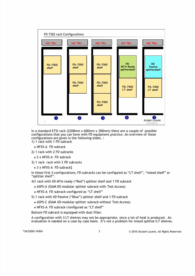
FD 7302 rack Configurations
NO TRU NO TRU NO TRU NO TRU NO TRU
FD-7302shelf
FD-7302shelf
FD-7302shelf
FD-7302shelf
FD-7302shelf
FD-7302shelf
XDMTA Readysplittershelf
FD-7302
LT shelf
XDPassive
splittershelf
FD-7302
LT shelf
In a standard ETSI rack (2200mm x 600mm x 300mm) there are a couple of possible
configurations that you can have with FD equipment practice. An overview of theseconfigurations are given in the following slides. :1) 1 rack with 1 FD subrack
NFXS-A FD subrack
2) 1 rack with 2 FD subracks
2 x NFXS-A FD subrack
3) 1 rack rack with 3 FD subracks
3 x NFXS-A FD subrack]
In these first 3 configurations, FD subracks can be configured as “LT shelf”, “mixed shelf” or“splitter shelf”.
4)1 rack with XD MTA-ready (“Red”) splitter shelf and 1 FD subrack
ASPS-A (ISAM XD-modular splitter subrack with Test Access)
NFXS-A FD subrack configured as “LT shelf”
5) 1 rack with XD Passive (“Blue”) splitter shelf and 1 FD subrack
ASPS-C (ISAM XD-modular splitter subrack without Test Access)
NFXS-A FD subrack cionfigured as “LT shelf”
Bottom FD subrack is equipped with dust filter.
A configuration with 3 LT shelves may not be appropriate, since a lot of heat is produced. Anevaluation is needed on a case by case basis. It’s not a problem for mixed splitter/LT shelves.
7/18/2019 Alu - A7302 Isam Fttu Operator Gpon Nant-e_ce-PDF
http://slidepdf.com/reader/full/alu-a7302-isam-fttu-operator-gpon-nant-ece-pdf 17/432
© 2010 Alcatel-Lucent, All Rights ReservedTAC03001-HO04 8
8
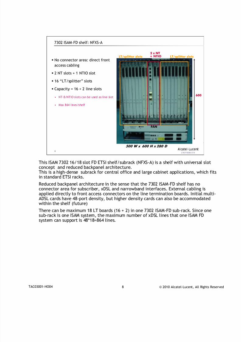
7302 ISAM–FD shelf: NFXS-A
No connector area: direct front
access cabling
2 NT slots + 1 NTIO slot
16 “LT/splitter” slots
Capacity = 16 + 2 line slots
• NT-B/NTIO slots can be used as line slot
• Max 864 lines/shelf
500 W x 600 H x 280 D
600
LT/splitter slots LT/splitter slots2 x NT+ NTIO
FAN
This ISAM 7302 16/18 slot FD ETSI shelf/subrack (NFXS-A) is a shelf with universal slot
concept and reduced backpanel architecture.This is a high-dense subrack for central office and large cabinet applications, which fitsin standard ETSI racks.
Reduced backpanel architecture in the sense that the 7302 ISAM-FD shelf has noconnector area for subscriber, xDSL and narrowband interfaces. External cabling isapplied directly to front access connectors on the line termination boards. Initial multi-ADSL cards have 48-port density, but higher density cards can also be accommodatedwithin the shelf (future)
There can be maximum 18 LT boards (16 + 2) in one 7302 ISAM-FD sub-rack. Since onesub-rack is one ISAM system, the maximum number of xDSL lines that one ISAM FD
system can support is 48*18=864 lines.
7/18/2019 Alu - A7302 Isam Fttu Operator Gpon Nant-e_ce-PDF
http://slidepdf.com/reader/full/alu-a7302-isam-fttu-operator-gpon-nant-ece-pdf 18/432
© 2010 Alcatel-Lucent, All Rights ReservedTAC03001-HO04 9
9
7302 ISAM–FD shelf: NFXS-A
Card cagearea
DSL
LT board
Back panel
FANdust filter
L T L T L T L T L T L T
L T
L T L T L T L T L T L T L T L T
L T
N T A
N T B / L T
N T I O / L T
Power &connector area
PWR
Dust filter
Fan unit
fiber conduct
Fan area
fiber channel
fiber conduct
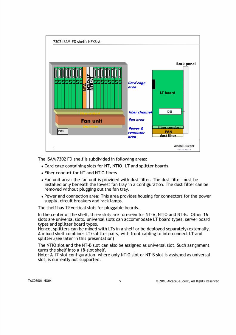
The ISAM 7302 FD shelf is subdivided in following areas:
Card cage containing slots for NT, NTIO, LT and splitter boards.
Fiber conduct for NT and NTIO fibers
Fan unit area: the fan unit is provided with dust filter. The dust filter must beinstalled only beneath the lowest fan tray in a configuration. The dust filter can beremoved without plugging out the fan tray.
Power and connection area: This area provides housing for connectors for the powersupply, circuit breakers and rack lamps.
The shelf has 19 vertical slots for pluggable boards.
In the center of the shelf, three slots are foreseen for NT-A, NTIO and NT-B. Other 16slots are universal slots. universal slots can accommodate LT board types, server boardtypes and splitter board types.Hence, splitters can be mixed with LTs in a shelf or be deployed separately/externally.A mixed shelf combines LT/splitter pairs, with front cabling to interconnect LT andsplitter.(see later in this presentation)
The NTIO slot and the NT-B slot can also be assigned as universal slot. Such assignmentturns the shelf into a 18-slot shelf.Note: A 17-slot configuration, where only NTIO slot or NT-B slot is assigned as universalslot, is currently not supported.
7/18/2019 Alu - A7302 Isam Fttu Operator Gpon Nant-e_ce-PDF
http://slidepdf.com/reader/full/alu-a7302-isam-fttu-operator-gpon-nant-ece-pdf 19/432
© 2010 Alcatel-Lucent, All Rights ReservedTAC03001-HO04 10
10
7302 ISAM-FD shelf – configurations LT shelves
XDSL cable management area
4 8 p - L T
Fan unit
4 8 p - L T
N T
N T I O
TAUBITS
Craft
BITS
Craft
Mgt
SFP4
SFP1
SFP5
SFP6
SFP7
SFP8
SFP3
SFP2 SFP2
N T
Mgt
SFP1
A D S L 1 - 4 8
connector
areaBAT filers
Inlet
Block
CBsLamps
connector
areaPWR filtersPWR
Inlet
Block
CBsLEDS
fiber management area
Fan unit
BPA
XDSL cable management area
4 8 p - L T
Fan unit
4 8 p - L T
N T
N T I O
TAUBITS
Craft
BITS
Craft
Mgt
SFP4
SFP1
SFP5
SFP6
SFP7
SFP8
SFP3
SFP2 SFP2
N T
Mgt
SFP1
A D S L 1 - 4 8
connector
areaBAT filers
Inlet
Block
CBsLamps
connector
areaPWR filtersPWR
Inlet
Block
CBsLEDS
fiber conduct area
Fan unit
BPA
FD CO 16 slot LT shelf
with NT redundancy
FD CO 18 slot LT shelf
no NTIO / no NT redundancy
(e.g. HSI only application)
XDSL cable management area
4 8 p - L T
Fan unit
4 8 p - L T
N T
N T I O
TAUBITS
Craft
BITS
Craft
Mgt
SFP4
SFP1
SFP5
SFP6
SFP7
SFP8
SFP3
SFP2 SFP2
N T
Mgt
SFP1
A D S L 1 - 4 8
connectorarea
BAT filersInletBlock
CBsLamps
connectorarea
PWR filtersPWR InletBlock
CBsLEDS
fibermanagement area
Fan unit
BPA
XDSL cable management area
4 8 p - L T
Fan unit
4 8 p - L T
N T
N T I O
TAUBITS
Craft
BITS
Craft
Mgt
SFP4
SFP1
SFP5
SFP6
SFP7
SFP8
SFP3
SFP2 SFP2
N T
Mgt
SFP1
A D S L 1 - 4 8
connectorarea
BAT filersInletBlock
CBsLamps
connectorarea
PWR filtersPWR InletBlock
CBsLEDS
fiber conduct area
Fan unit
BPA
XDSL XDSL
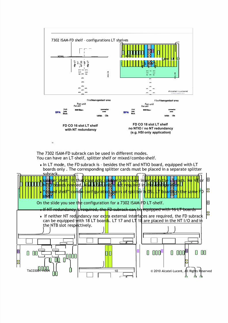
The 7302 ISAM-FD subrack can be used in different modes.
You can have an LT-shelf, splitter shelf or mixed/combo-shelf.
In LT mode, the FD subrack is – besides the NT and NTIO board, equipped with LTboards only . The corresponding splitter cards must be placed in a separate splittersubrack.
splitter shelf: In that case only splitter boards are inserted in the LT-slots. No NT orNTIO boards needed. Also a fan unit is not required in this configuration.
“mixed shelf”-combo configuration, pairs of splitter & DSL LT boards in the same FDshelf.
On the slide you see the configuration for a 7302 ISAM-FD LT-shelf.
If NT redundancy is required, the FD subrack can be equipped with 16 LT boards If neither NT redundancy nor extra external interfaces are required, the FD subrack
can be equipped with 18 LT boards. LT 17 and LT 18 are placed in the NT I/O and inthe NTB slot respectively.
7/18/2019 Alu - A7302 Isam Fttu Operator Gpon Nant-e_ce-PDF
http://slidepdf.com/reader/full/alu-a7302-isam-fttu-operator-gpon-nant-ece-pdf 20/432
© 2010 Alcatel-Lucent, All Rights ReservedTAC03001-HO04 11
11
7302 ISAM FD shelf – configurations LT/splitter shelf
FD CO 16 slot shelf
with NT redundancy
4 8 p - L T
Fan unit
4 8 p - L T
N T
N T
I O
TAUBITS
Craft
BITS
Craft
Mgt
SFP4
SFP1
SFP5
SFP6
SFP7
SFP8
SFP3
SFP2 SFP2
N T
Mgt
SFP1
A D S L 1 - 4 8
Connectorarea
BAT filersInletBlock
CBsLamps
Connectorarea
PWR filtersPWR InletBlock
CBsLEDS
Fiber management areaFan Unit
BPA
POTSLINE
XDSL
LT SP LT SP
4 8 p - L T
Fan unit
4 8 p - L T
N T
N T
I O
TAUBITS
Craft
BITS
Craft
Mgt
SFP4
SFP1
SFP5
SFP6
SFP7
SFP8
SFP3
SFP2 SFP2
N T
Mgt
SFP1
A D S L 1 - 4 8
Connectorarea
BAT filersInletBlock
CBsLamps
Connectorarea
PWR filtersPWR InletBlock
CBsLEDS
Fiber management areaFan Unit
BPA
POTSLINE
XDSL
LT SPLT SP LT SPLT SP
FD CO 18 slot shelf
without NT redundancy
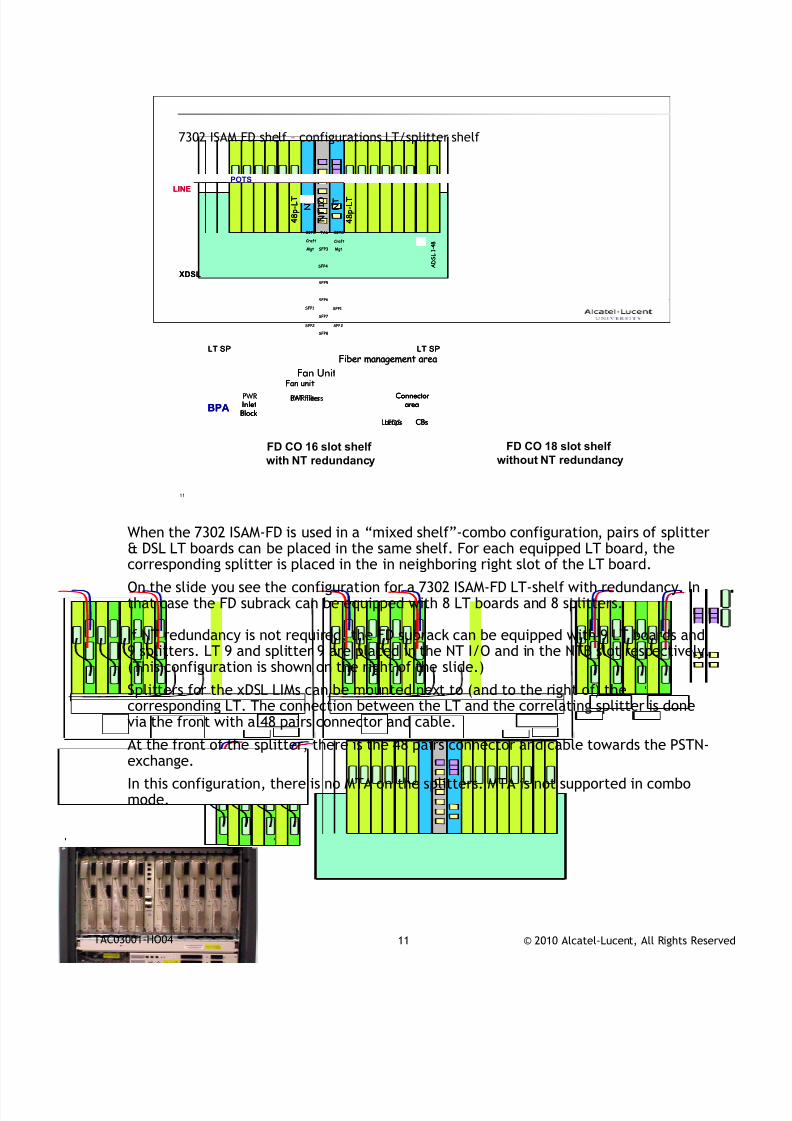
When the 7302 ISAM-FD is used in a “mixed shelf”-combo configuration, pairs of splitter
& DSL LT boards can be placed in the same shelf. For each equipped LT board, thecorresponding splitter is placed in the in neighboring right slot of the LT board.
On the slide you see the configuration for a 7302 ISAM-FD LT-shelf with redundancy. Inthat case the FD subrack can be equipped with 8 LT boards and 8 splitters.
If NT redundancy is not required, the FD subrack can be equipped with 9 LT boards and9 splitters. LT 9 and splitter 9 are placed in the NT I/O and in the NTB slot respectively.(This configuration is shown on the right of the slide.)
Splitters for the xDSL LIMs can be mounted next to (and to the right of) thecorresponding LT. The connection between the LT and the correlating splitter is done
via the front with a 48 pairs connector and cable.At the front of the splitter, there is the 48 pairs connector and cable towards the PSTN-exchange.
In this configuration, there is no MTA on the splitters. MTA is not supported in combomode.
7/18/2019 Alu - A7302 Isam Fttu Operator Gpon Nant-e_ce-PDF
http://slidepdf.com/reader/full/alu-a7302-isam-fttu-operator-gpon-nant-ece-pdf 21/432
© 2010 Alcatel-Lucent, All Rights ReservedTAC03001-HO04 12
12
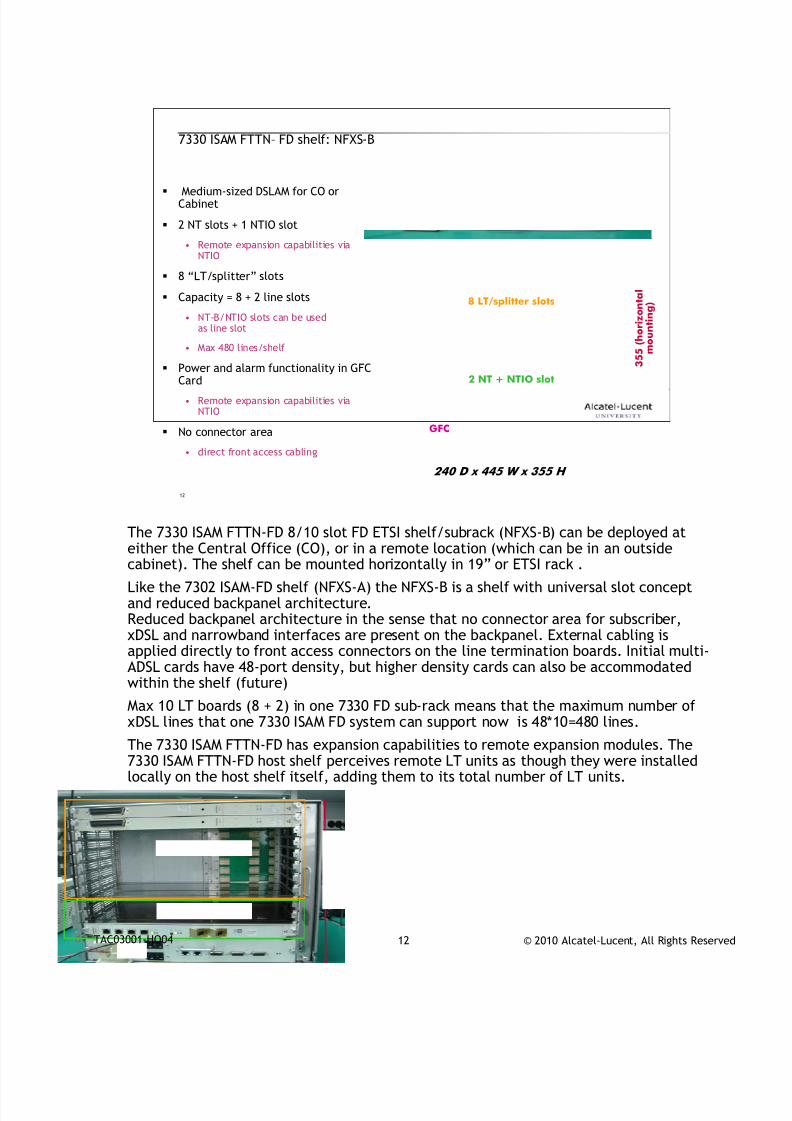
7330 ISAM FTTN– FD shelf: NFXS-B
Medium-sized DSLAM for CO orCabinet
2 NT slots + 1 NTIO slot
• Remote expansion capabilities viaNTIO
8 “LT/splitter” slots
Capacity = 8 + 2 line slots
• NT-B/NTIO slots can be usedas line slot
• Max 480 lines/shelf
Power and alarm functionality in GFCCard
• Remote expansion capabilities viaNTIO
No connector area
• direct front access cabling
3
5 5 ( h o r i z o n t a l
m o u n t i n g )
240 D x 445 W x 355 H
8 LT/splitter slots
2 NT + NTIO slot
GFC
The 7330 ISAM FTTN-FD 8/10 slot FD ETSI shelf/subrack (NFXS-B) can be deployed at
either the Central Office (CO), or in a remote location (which can be in an outsidecabinet). The shelf can be mounted horizontally in 19” or ETSI rack .
Like the 7302 ISAM-FD shelf (NFXS-A) the NFXS-B is a shelf with universal slot conceptand reduced backpanel architecture.Reduced backpanel architecture in the sense that no connector area for subscriber,xDSL and narrowband interfaces are present on the backpanel. External cabling isapplied directly to front access connectors on the line termination boards. Initial multi-ADSL cards have 48-port density, but higher density cards can also be accommodatedwithin the shelf (future)
Max 10 LT boards (8 + 2) in one 7330 FD sub-rack means that the maximum number of
xDSL lines that one 7330 ISAM FD system can support now is 48*10=480 lines.The 7330 ISAM FTTN-FD has expansion capabilities to remote expansion modules. The7330 ISAM FTTN-FD host shelf perceives remote LT units as though they were installedlocally on the host shelf itself, adding them to its total number of LT units.
7/18/2019 Alu - A7302 Isam Fttu Operator Gpon Nant-e_ce-PDF
http://slidepdf.com/reader/full/alu-a7302-isam-fttu-operator-gpon-nant-ece-pdf 22/432
© 2010 Alcatel-Lucent, All Rights ReservedTAC03001-HO04 13
13
7330 ISAM FTTN–FD shelf: NFXS-B
LT
LT
LT
LT
LT
LT
LT
LT
NT-A
NTIO / LT
NT-B / LT
F an uni t
Card cage area
Power &connector area
Fan area
GFCPWR
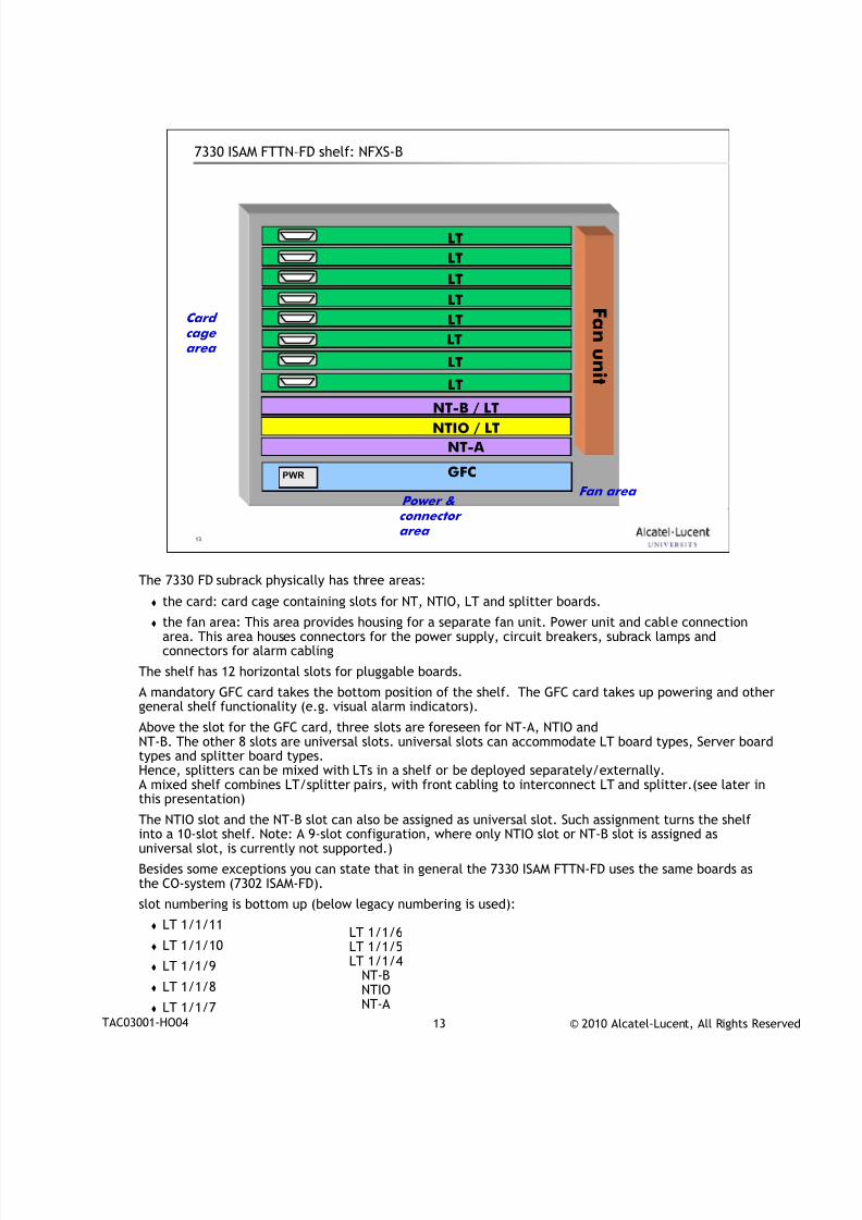
The 7330 FD subrack physically has three areas:
the card: card cage containing slots for NT, NTIO, LT and splitter boards.
the fan area: This area provides housing for a separate fan unit. Power unit and cable connectionarea. This area houses connectors for the power supply, circuit breakers, subrack lamps andconnectors for alarm cabling
The shelf has 12 horizontal slots for pluggable boards.
A mandatory GFC card takes the bottom position of the shelf. The GFC card takes up powering and othergeneral shelf functionality (e.g. visual alarm indicators).
Above the slot for the GFC card, three slots are foreseen for NT-A, NTIO andNT-B. The other 8 slots are universal slots. universal slots can accommodate LT board types, Server boardtypes and splitter board types.Hence, splitters can be mixed with LTs in a shelf or be deployed separately/externally.A mixed shelf combines LT/splitter pairs, with front cabling to interconnect LT and splitter.(see later inthis presentation)
The NTIO slot and the NT-B slot can also be assigned as universal slot. Such assignment turns the shelfinto a 10-slot shelf. Note: A 9-slot configuration, where only NTIO slot or NT-B slot is assigned asuniversal slot, is currently not supported.)
Besides some exceptions you can state that in general the 7330 ISAM FTTN-FD uses the same boards asthe CO-system (7302 ISAM-FD).
slot numbering is bottom up (below legacy numbering is used):
LT 1/1/11
LT 1/1/10
LT 1/1/9
LT 1/1/8 LT 1/1/7
LT 1/1/6LT 1/1/5LT 1/1/4
NT-B
NTIONT-A
7/18/2019 Alu - A7302 Isam Fttu Operator Gpon Nant-e_ce-PDF
http://slidepdf.com/reader/full/alu-a7302-isam-fttu-operator-gpon-nant-ece-pdf 23/432
© 2010 Alcatel-Lucent, All Rights ReservedTAC03001-HO04 14
14
7330 ISAM FD shelf – configurations
F a n u n i t
N T
N T I O T A U
B I T S
C r a f t
B I T S
C r a f t
M g t
S F P 4
S F P 1
S F P 5
S F P 6
S F P 7
S F P 8
S F P 3
S F P 2
S F P 2
N T M g t
S F P 1
A D S L 1 - 4 8
f i b e r
m a n a g e m e n t a r e a
F a n
u n i t
F a n u n i t
48p -
LT
NT
NT IO T A U
B I T S
C r a f t
M g t
S F P 4
S F P 1
S F P 5
S F P 6
S F P 7
S F P 8
S F P 3
S F P 2
S F P 2
NT S
F P 1
ADSL 1 -
48
F a n
u n i t
C r a f t
M g t
B I T S
F a n u n i t
S F P 2
N T S F P 1
A D S L 1 - 4 8
f i b e r
m a n a g e m e n t a r e a
F a n
u n i t
F a n u n i t
S F P 2
NT S F P 1
ADSL 1 -
48
F a n
u n i t
C r a f t
M g t
B I T S
4 8 p - L T
4 8 p - L T 48p-LT
FD CO 8 slot LT shelf
With NT redundancy
FD CO 10 slot LT shelf
No NTIO/ No NT redundancy
(e.g. HSI only application)
LT8
LT10
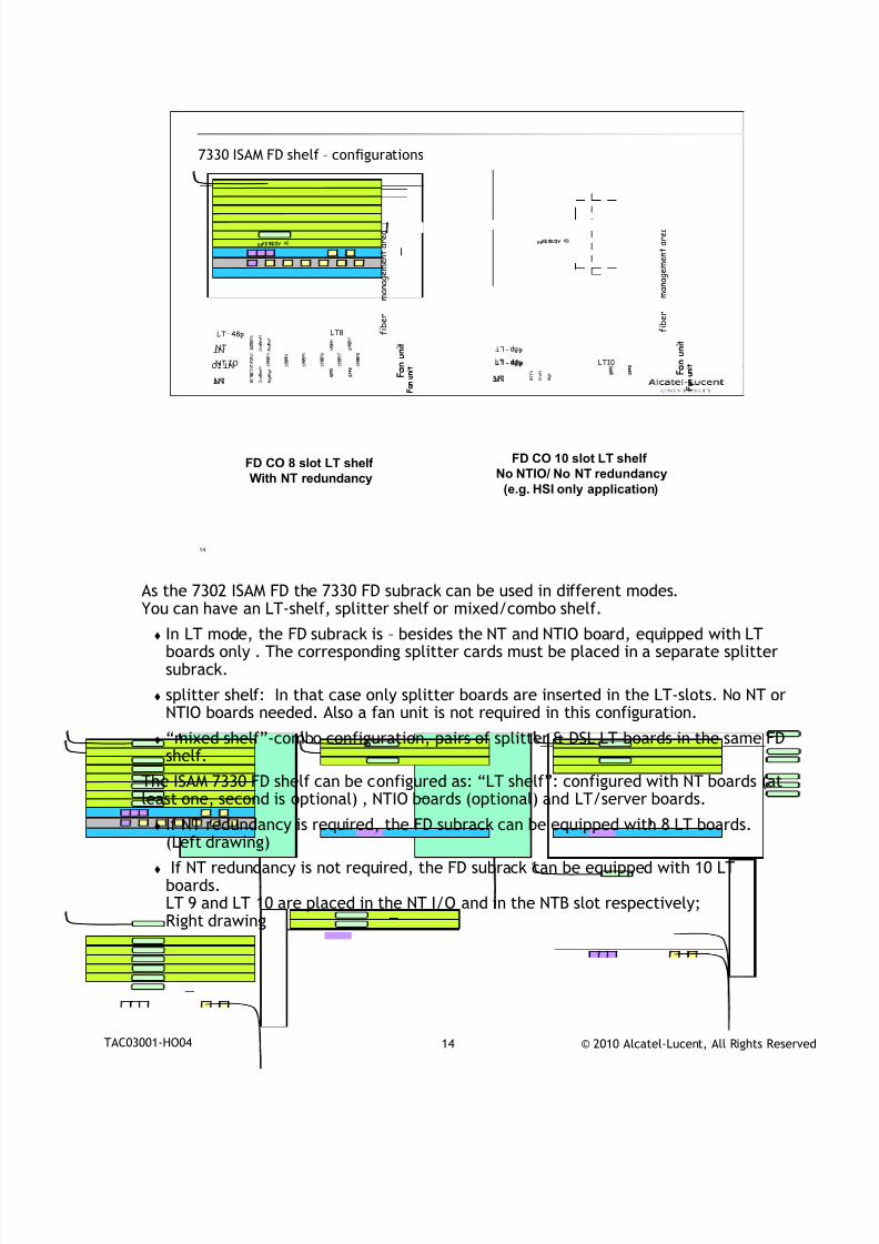
As the 7302 ISAM FD the 7330 FD subrack can be used in different modes.
You can have an LT-shelf, splitter shelf or mixed/combo shelf.
In LT mode, the FD subrack is – besides the NT and NTIO board, equipped with LTboards only . The corresponding splitter cards must be placed in a separate splittersubrack.
splitter shelf: In that case only splitter boards are inserted in the LT-slots. No NT orNTIO boards needed. Also a fan unit is not required in this configuration.
“mixed shelf”-combo configuration, pairs of splitter & DSL LT boards in the same FDshelf.
The ISAM 7330 FD shelf can be configured as: “LT shelf”: configured with NT boards (atleast one, second is optional) , NTIO boards (optional) and LT/server boards.
If NT redundancy is required, the FD subrack can be equipped with 8 LT boards.(Left drawing)
If NT redundancy is not required, the FD subrack can be equipped with 10 LTboards.LT 9 and LT 10 are placed in the NT I/O and in the NTB slot respectively;Right drawing
7/18/2019 Alu - A7302 Isam Fttu Operator Gpon Nant-e_ce-PDF
http://slidepdf.com/reader/full/alu-a7302-isam-fttu-operator-gpon-nant-ece-pdf 24/432
© 2010 Alcatel-Lucent, All Rights ReservedTAC03001-HO04 15
15
7330 ISAM FD shelf – configurations
F
a n u n i t
N T
T A U
B I T S
C r a f t
S F P 4
S F P 1
S F P 5
S F P 6
S F P 7
S F P 8
S F P 3
S F P 2
S F P 2
N T M g t
S F P 1 F
a n
u n i t
F
a n u n i t
NT
NT IO T A U
B I T S
C r a f t
M g t
S F P 4
S F P 1
S F P 5
S F P 6
S F P 7
S F P 8
S F P 3
S F P 2
S F P 2
NT S F P 1
F a n
u n i t
C r a f t
M g t
B I T S
FD CO mixed shelf
With NT redundancy
L T
S P
--
-
P O T S
L I N E
-
XDSL LT1
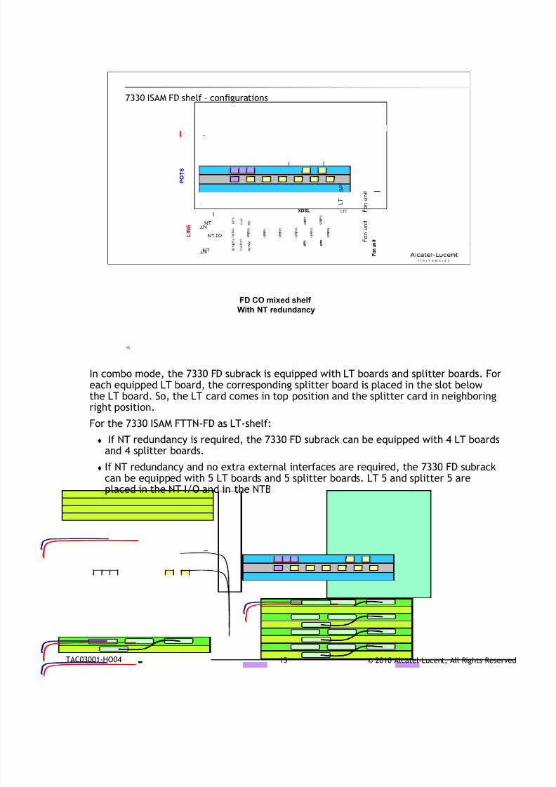
In combo mode, the 7330 FD subrack is equipped with LT boards and splitter boards. For
each equipped LT board, the corresponding splitter board is placed in the slot belowthe LT board. So, the LT card comes in top position and the splitter card in neighboringright position.
For the 7330 ISAM FTTN-FD as LT-shelf:
If NT redundancy is required, the 7330 FD subrack can be equipped with 4 LT boardsand 4 splitter boards.
If NT redundancy and no extra external interfaces are required, the 7330 FD subrackcan be equipped with 5 LT boards and 5 splitter boards. LT 5 and splitter 5 areplaced in the NT I/O and in the NTB
7/18/2019 Alu - A7302 Isam Fttu Operator Gpon Nant-e_ce-PDF
http://slidepdf.com/reader/full/alu-a7302-isam-fttu-operator-gpon-nant-ece-pdf 25/432
© 2010 Alcatel-Lucent, All Rights ReservedTAC03001-HO04 16
16
General architecture 7302 ISAM-FD
new equipment practice – NEP
• NFXS-A
capacity = 16 + 2 line slots
• NT-B/NTIO slots can be used as line slot
universal slot concept
• shelf can accomodate any mix ofxDSL LTs, splitters, fiber LTs,voice cards
aggregation (service hub) andcontrol- & management function integratedon NT
1GE connectivity betweenNT and LT via backpanel
• Backplane ready to support evolution to higherdensities
ACU & clock function integrated on NTboard
SMAS functionality integrated on backpanel
7302 FD-shelf
ASAM link
Control link
NT
Aggregationfunction (SHUB)
1 …16/18 GE2 GE
1..6 GE2 ExternalEthernetlinks
Control/Mgtfunctions ACU Clock
6 ExternalEthernetlinks
LT16 18orSP16 18ormixed
SMAS
NTIO 802.3port
802.3port
Power
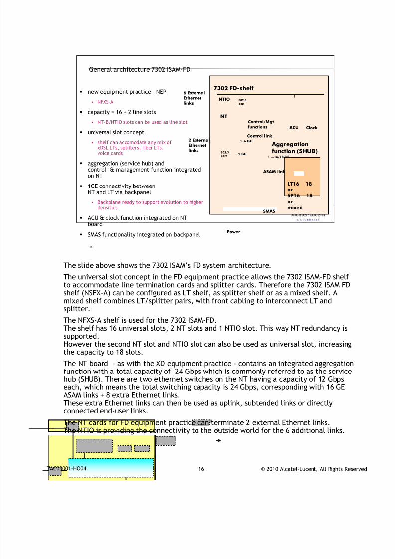
The slide above shows the 7302 ISAM’s FD system architecture.
The universal slot concept in the FD equipment practice allows the 7302 ISAM-FD shelfto accommodate line termination cards and splitter cards. Therefore the 7302 ISAM FDshelf (NSFX-A) can be configured as LT shelf, as splitter shelf or as a mixed shelf. Amixed shelf combines LT/splitter pairs, with front cabling to interconnect LT andsplitter.
The NFXS-A shelf is used for the 7302 ISAM-FD.The shelf has 16 universal slots, 2 NT slots and 1 NTIO slot. This way NT redundancy issupported.However the second NT slot and NTIO slot can also be used as universal slot, increasingthe capacity to 18 slots.
The NT board - as with the XD equipment practice - contains an integrated aggregationfunction with a total capacity of 24 Gbps which is commonly referred to as the servicehub (SHUB). There are two ethernet switches on the NT having a capacity of 12 Gbpseach, which means the total switching capacity is 24 Gbps, corresponding with 16 GEASAM links + 8 extra Ethernet links.These extra Ethernet links can then be used as uplink, subtended links or directlyconnected end-user links.
The NT cards for FD equipment practice can terminate 2 external Ethernet links.The NTIO is providing the connectivity to the outside world for the 6 additional links.
7/18/2019 Alu - A7302 Isam Fttu Operator Gpon Nant-e_ce-PDF
http://slidepdf.com/reader/full/alu-a7302-isam-fttu-operator-gpon-nant-ece-pdf 26/432
© 2010 Alcatel-Lucent, All Rights ReservedTAC03001-HO04 17
In the case where the second NT slot and NTIO slot are used as universal slots,2 of these 8 Ethernet links are used as ASAM-links leaving us with 6 uplinks available on theSHUB. As said before the NT in FD equipment provides connectivity to the outside world fortwo of these links. So in that case 4 uplinks will remain unused.Clocking and alarm control unit functionality are also provided on the NT
Each LT card is connected with the NT (SHUB) via the backpanel using a1 GE electrical interface (ASAM-links). The backplane of the FD however is ready tosupport evolution to higher densities and higher subscriber bandwidths.
Powering and other general shelf functionality (e.g. visual alarm indicators) (= thepower unit) is integrated in the 7302 ISAM FD shelf . This way the FD shelf canoperate as a a stand-alone unit, allowing the operator to install the 7302 ISAM FD in
any standard ETSI 2200 rack..
You do not find the TAU module on this drawing, although ISAM FD equipmentpractice provides this functionality in LT mode. MTA is not supported in combomode. An RJ45 for test access (connection to TAU) is present on the NTIO ( seelater), but the TAU module itself is on a TAUS-card which physically needs to beinserted in the splitter-shelf.
The SMAS functionality (Remote Inventory PROM) is placed in a socket which isplugged on the backplane.
7/18/2019 Alu - A7302 Isam Fttu Operator Gpon Nant-e_ce-PDF
http://slidepdf.com/reader/full/alu-a7302-isam-fttu-operator-gpon-nant-ece-pdf 27/432
© 2010 Alcatel-Lucent, All Rights ReservedTAC03001-HO04 18
18
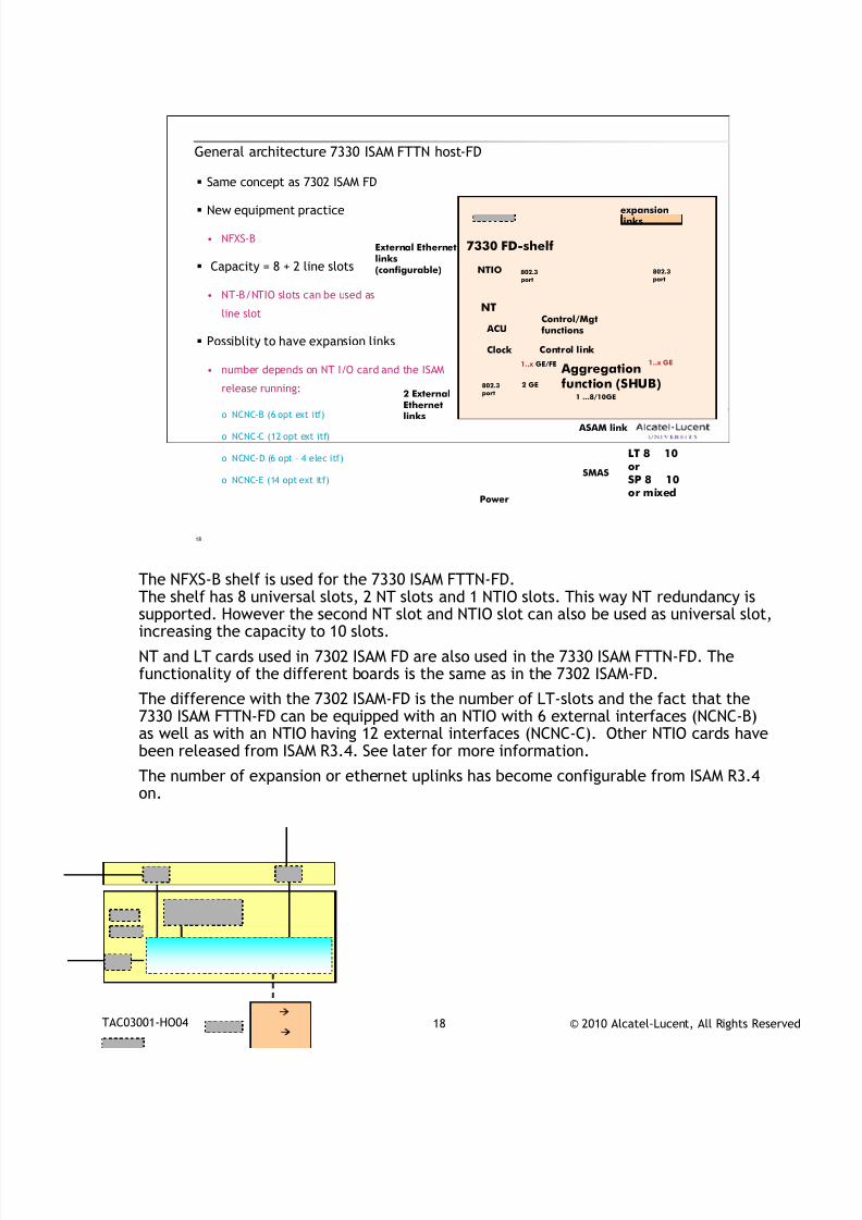
General architecture 7330 ISAM FTTN host-FD
Same concept as 7302 ISAM FD
New equipment practice
• NFXS-B
Capacity = 8 + 2 line slots
• NT-B/NTIO slots can be used as
line slot
Possiblity to have expansion links
• number depends on NT I/O card and the ISAM
release running:
o NCNC-B (6 opt ext itf)
o NCNC-C (12 opt ext itf)
o NCNC-D (6 opt – 4 elec itf)
o NCNC-E (14 opt ext itf)
7330 FD-shelf
ASAM link
Control link
NT
Aggregationfunction (SHUB)
1 …8/10GE
2 GE
1..x GE/FE
Control/Mgtfunctions ACU
Clock
LT 8 10orSP 8 10or mixed
SMAS
NTIO 802.3port
802.3
port
Power
802.3port
expansionlinks
1..x GE
2 ExternalEthernetlinks
External Ethernetlinks(configurable)
The NFXS-B shelf is used for the 7330 ISAM FTTN-FD.
The shelf has 8 universal slots, 2 NT slots and 1 NTIO slots. This way NT redundancy issupported. However the second NT slot and NTIO slot can also be used as universal slot,increasing the capacity to 10 slots.
NT and LT cards used in 7302 ISAM FD are also used in the 7330 ISAM FTTN-FD. Thefunctionality of the different boards is the same as in the 7302 ISAM-FD.
The difference with the 7302 ISAM-FD is the number of LT-slots and the fact that the7330 ISAM FTTN-FD can be equipped with an NTIO with 6 external interfaces (NCNC-B)as well as with an NTIO having 12 external interfaces (NCNC-C). Other NTIO cards havebeen released from ISAM R3.4. See later for more information.
The number of expansion or ethernet uplinks has become configurable from ISAM R3.4
on.

7/18/2019 Alu - A7302 Isam Fttu Operator Gpon Nant-e_ce-PDF
http://slidepdf.com/reader/full/alu-a7302-isam-fttu-operator-gpon-nant-ece-pdf 28/432
© 2010 Alcatel-Lucent, All Rights ReservedTAC03001-HO04 19
19
Board Types2
7/18/2019 Alu - A7302 Isam Fttu Operator Gpon Nant-e_ce-PDF
http://slidepdf.com/reader/full/alu-a7302-isam-fttu-operator-gpon-nant-ece-pdf 29/432
© 2010 Alcatel-Lucent, All Rights ReservedTAC03001-HO04 20
20
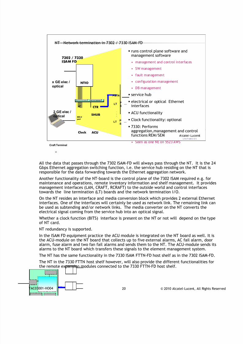
NT – Network termination in 7302 / 7330 ISAM-FD
runs control plane software and
management software• management and control interfaces
• SW management
• fault management
• configuration management
• DB management
service hub
electrical or optical Ethernetinterfaces
ACU functionality
Clock functionality: optional
7330: Performsaggregation,management and controlfunctions REM/SEM
• Seen as one NE on 5523 AWS
2 GE elec /optical
Craft Terminal
7302 / 7330ISAM FD
.
.
.
PSTN
…P
SLT
…P
SLT
NT
SHUB
CTR
802.3port
Clock ACU
NTIOx GE elec /
optical
All the data that passes through the 7302 ISAM-FD will always pass through the NT. It is the 24
Gbps Ethernet aggregation switching function, i.e. the service hub residing on the NT that isresponsible for the data forwarding towards the Ethernet aggregation network.
Another functionality of the NT-board is the control plane of the 7302 ISAM required e.g. formaintenance and operations, remote inventory information and shelf management. It providesmanagement interfaces (LAN, CRAFT, RCRAFT) to the outside world and control interfacestowards the line termination (LT) boards and the network termination I/O.
On the NT resides an interface and media conversion block which provides 2 external Ethernetinterfaces. One of the interfaces will certainly be used as network link. The remaining link canbe used as subtending and/or network links. The media converter on the NT converts theelectrical signal coming from the service hub into an optical signal.
Whether a clock function (BITS) interface is present on the NT or not will depend on the type
of NT card.NT redundancy is supported.
In the ISAM FD equipment practice the ACU module is integrated on the NT board as well. It isthe ACU-module on the NT board that collects up to five external alarms, AC fail alarm, dooralarm, fuse alarm and two fan fail alarms and sends them to the NT. The ACU-module sends itsalarms to the NT board which transfers these signals to the element management system.
The NT has the same functionality in the 7330 ISAM FTTN-FD host shelf as in the 7302 ISAM-FD.
The NT in the 7330 FTTN host shelf however, will also provide the different functionalities forthe remote expansion modules connected to the 7330 FTTN-FD host shelf.
7/18/2019 Alu - A7302 Isam Fttu Operator Gpon Nant-e_ce-PDF
http://slidepdf.com/reader/full/alu-a7302-isam-fttu-operator-gpon-nant-ece-pdf 30/432
© 2010 Alcatel-Lucent, All Rights ReservedTAC03001-HO04 21
21
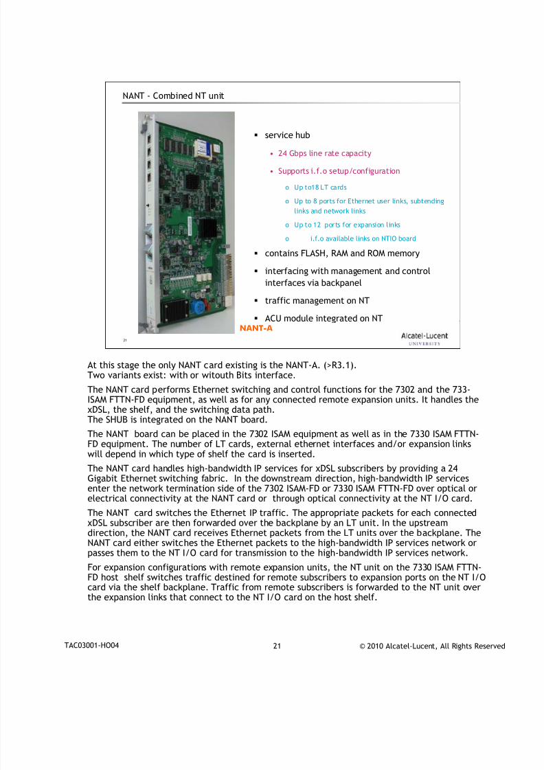
NANT - Combined NT unit
service hub
• 24 Gbps line rate capacity
• Supports i.f.o setup/configuration
o Up to18 LT cards
o Up to 8 ports for Ethernet user links, subtending
links and network links
o Up to 12 ports for expansion links
o i.f.o available links on NTIO board
contains FLASH, RAM and ROM memory
interfacing with management and control
interfaces via backpanel
traffic management on NT
ACU module integrated on NTNANT-A
At this stage the only NANT card existing is the NANT-A. (>R3.1).
Two variants exist: with or witouth Bits interface.The NANT card performs Ethernet switching and control functions for the 7302 and the 733-ISAM FTTN-FD equipment, as well as for any connected remote expansion units. It handles thexDSL, the shelf, and the switching data path.The SHUB is integrated on the NANT board.
The NANT board can be placed in the 7302 ISAM equipment as well as in the 7330 ISAM FTTN-FD equipment. The number of LT cards, external ethernet interfaces and/or expansion linkswill depend in which type of shelf the card is inserted.
The NANT card handles high-bandwidth IP services for xDSL subscribers by providing a 24Gigabit Ethernet switching fabric. In the downstream direction, high-bandwidth IP servicesenter the network termination side of the 7302 ISAM-FD or 7330 ISAM FTTN-FD over optical or
electrical connectivity at the NANT card or through optical connectivity at the NT I/O card.The NANT card switches the Ethernet IP traffic. The appropriate packets for each connectedxDSL subscriber are then forwarded over the backplane by an LT unit. In the upstreamdirection, the NANT card receives Ethernet packets from the LT units over the backplane. TheNANT card either switches the Ethernet packets to the high-bandwidth IP services network orpasses them to the NT I/O card for transmission to the high-bandwidth IP services network.
For expansion configurations with remote expansion units, the NT unit on the 7330 ISAM FTTN-FD host shelf switches traffic destined for remote subscribers to expansion ports on the NT I/Ocard via the shelf backplane. Traffic from remote subscribers is forwarded to the NT unit overthe expansion links that connect to the NT I/O card on the host shelf.
7/18/2019 Alu - A7302 Isam Fttu Operator Gpon Nant-e_ce-PDF
http://slidepdf.com/reader/full/alu-a7302-isam-fttu-operator-gpon-nant-ece-pdf 31/432
© 2010 Alcatel-Lucent, All Rights ReservedTAC03001-HO04 22
22
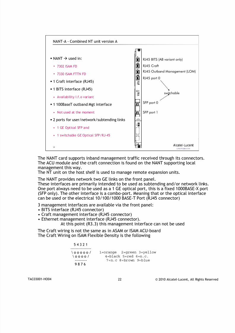
NANT-A - Combined NT unit version A
NANT used in:
• 7302 ISAM FD
• 7330 ISAM FTTN FD
1 Craft interface (RJ45)
1 BITS interface (RJ45)
• Availability I.f.o variant
1 100BaseT outband Mgt interface
• Not used at the moment
2 ports for user/network/subtending links
• 1 GE Optical SFP and
• 1 switchable GE Optical SFP/RJ-45
RJ45 BITS (AB variant only)
RJ45 Craft
RJ45 Outband Management (LOM)
RJ45 port 0
SFP port 0
SFP port 1
switchable
The NANT card supports inband management traffic received through its connectors.
The ACU module and the craft connection is found on the NANT supporting localmanagement this way.The NT unit on the host shelf is used to manage remote expansion units.
The NANT provides network two GE links on the front panel.These interfaces are primarily intended to be used as subtending and/or network links.One port always need to be used as a 1 GE optical port, this is a fixed 1000BASE-X port(SFP only). The other interface is a combo-port. Meaning that or the optical interfacecan be used or the electrical 10/100/1000 BASE-T Port (RJ45 connector)
3 management interfaces are available via the front panel:• BITS interface (RJ45 connector)
• Craft management interface (RJ45 connector)• Ethernet management interface (RJ45 connector).At this point (R3.3) this management interface can not be used
The Craft wiring is not the same as in ASAM or ISAM ACU-boardThe Craft Wiring on ISAM Flexible Density is the following
5 4 3 2 1---------------- \ o o o o o / \ o o o o /
---------9 8 7 6
1=orange 2=green 3=yellow
4=black 5=red 6=n.c.
7=n.c 8=brown 9=blue
7/18/2019 Alu - A7302 Isam Fttu Operator Gpon Nant-e_ce-PDF
http://slidepdf.com/reader/full/alu-a7302-isam-fttu-operator-gpon-nant-ece-pdf 32/432
© 2010 Alcatel-Lucent, All Rights ReservedTAC03001-HO04 23
23
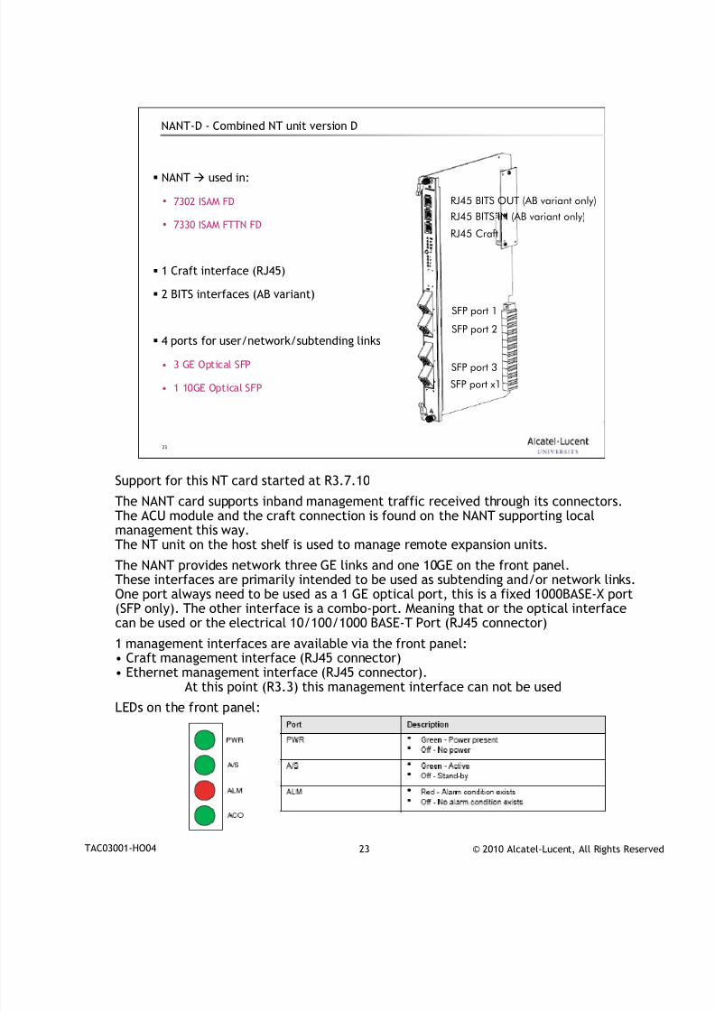
NANT-D - Combined NT unit version D
NANT used in:
• 7302 ISAM FD
• 7330 ISAM FTTN FD
1 Craft interface (RJ45)
2 BITS interfaces (AB variant)
4 ports for user/network/subtending links
• 3 GE Optical SFP
• 1 10GE Optical SFP
RJ45 Craft
RJ45 BITS OUT (AB variant only)
SFP port 1
SFP port 2
SFP port 3
SFP port x1
RJ45 BITS IN (AB variant only)
Support for this NT card started at R3.7.10
The NANT card supports inband management traffic received through its connectors.The ACU module and the craft connection is found on the NANT supporting localmanagement this way.The NT unit on the host shelf is used to manage remote expansion units.
The NANT provides network three GE links and one 10GE on the front panel.These interfaces are primarily intended to be used as subtending and/or network links.One port always need to be used as a 1 GE optical port, this is a fixed 1000BASE-X port(SFP only). The other interface is a combo-port. Meaning that or the optical interfacecan be used or the electrical 10/100/1000 BASE-T Port (RJ45 connector)
1 management interfaces are available via the front panel:
• Craft management interface (RJ45 connector)• Ethernet management interface (RJ45 connector).
At this point (R3.3) this management interface can not be used
LEDs on the front panel:
7/18/2019 Alu - A7302 Isam Fttu Operator Gpon Nant-e_ce-PDF
http://slidepdf.com/reader/full/alu-a7302-isam-fttu-operator-gpon-nant-ece-pdf 33/432
© 2010 Alcatel-Lucent, All Rights ReservedTAC03001-HO04 24
24
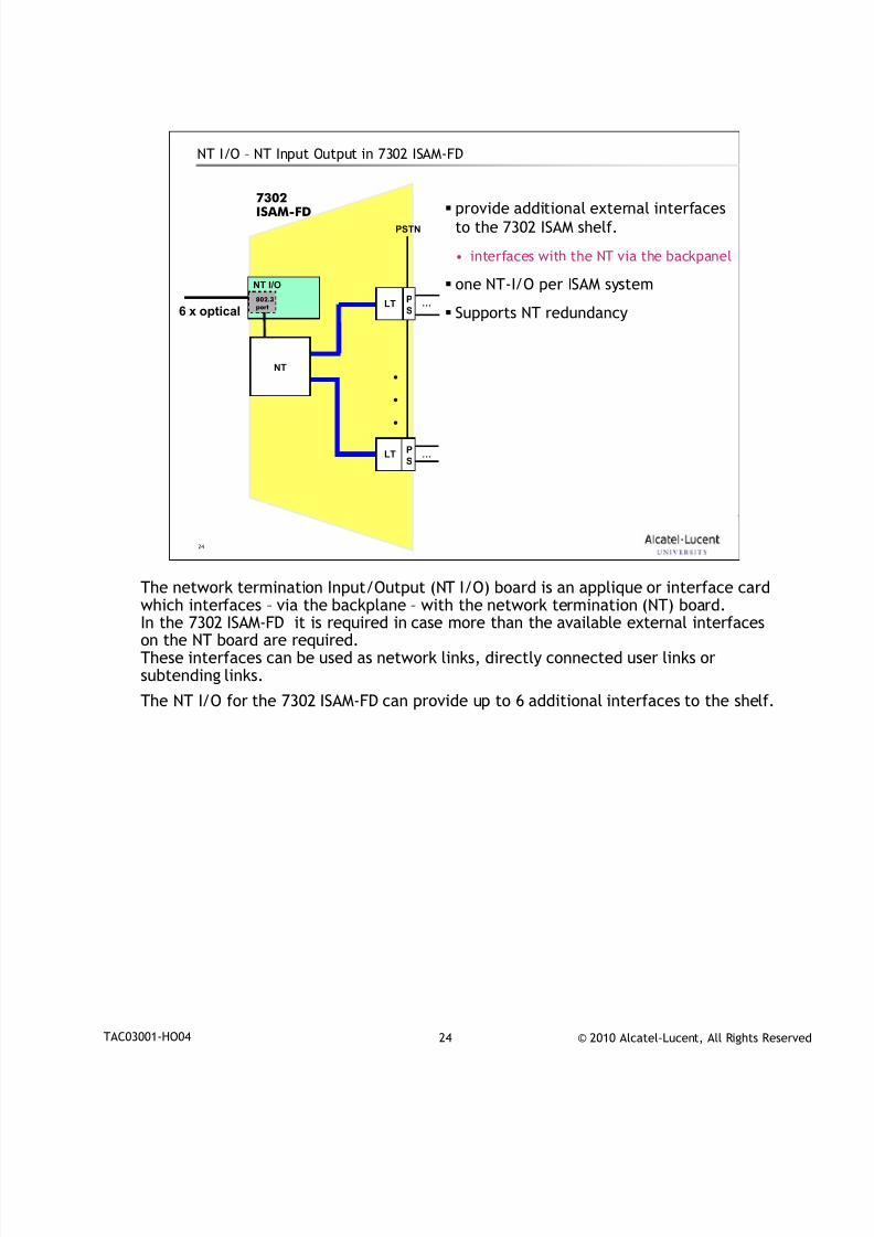
NT I/O – NT Input Output in 7302 ISAM-FD
provide additional external interfaces
to the 7302 ISAM shelf.
• interfaces with the NT via the backpanel
one NT-I/O per ISAM system
Supports NT redundancy
LT
.
..
…
…P
S
P
S
PSTN
7302ISAM-FD
NT I/O
LT
NT
6 x optical802.3port
The network termination Input/Output (NT I/O) board is an applique or interface card
which interfaces – via the backplane – with the network termination (NT) board.In the 7302 ISAM-FD it is required in case more than the available external interfaceson the NT board are required.These interfaces can be used as network links, directly connected user links orsubtending links.
The NT I/O for the 7302 ISAM-FD can provide up to 6 additional interfaces to the shelf.
7/18/2019 Alu - A7302 Isam Fttu Operator Gpon Nant-e_ce-PDF
http://slidepdf.com/reader/full/alu-a7302-isam-fttu-operator-gpon-nant-ece-pdf 34/432
© 2010 Alcatel-Lucent, All Rights ReservedTAC03001-HO04 25
25
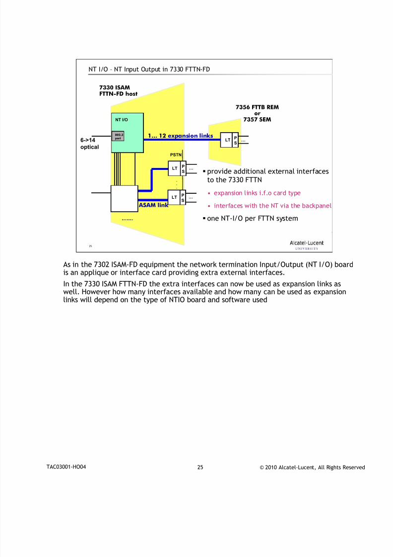
NT I/O – NT Input Output in 7330 FTTN-FD
provide additional external interfaces
to the 7330 FTTN
• expansion links i.f.o card type
• interfaces with the NT via the backpanel
one NT-I/O per FTTN system
7330 ISAMFTTN-FD host
…P
SLT
1… 12 expansion links
.
.
.
PSTN
…P
SLT
…P
SLT
ASAM link
6->14
optical
NT I/O
802.3port
7356 FTTB REMor
7357 SEM
As in the 7302 ISAM-FD equipment the network termination Input/Output (NT I/O) board
is an applique or interface card providing extra external interfaces.
In the 7330 ISAM FTTN-FD the extra interfaces can now be used as expansion links aswell. However how many interfaces available and how many can be used as expansionlinks will depend on the type of NTIO board and software used
7/18/2019 Alu - A7302 Isam Fttu Operator Gpon Nant-e_ce-PDF
http://slidepdf.com/reader/full/alu-a7302-isam-fttu-operator-gpon-nant-ece-pdf 35/432
© 2010 Alcatel-Lucent, All Rights ReservedTAC03001-HO04 26
26
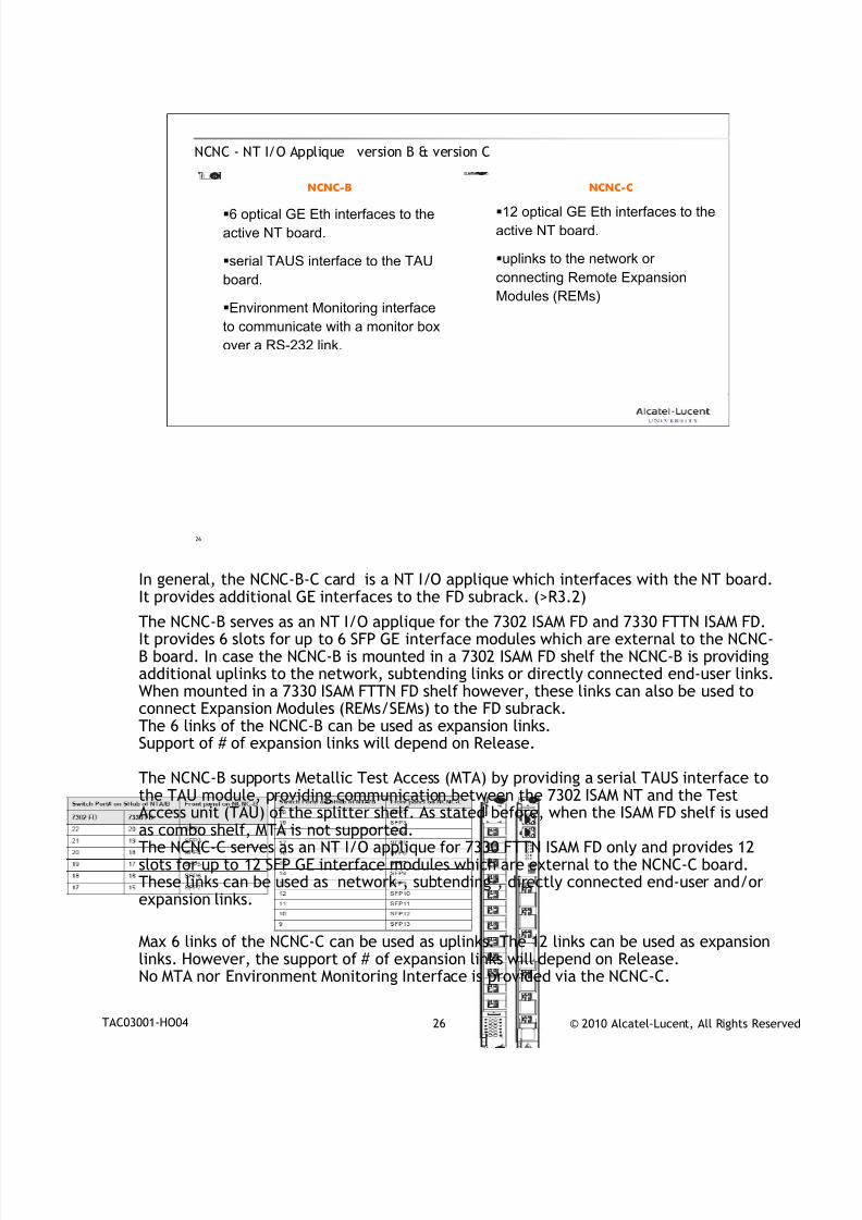
NCNC - NT I/O Applique version B & version C
6 optical GE Eth interfaces to the
active NT board.
serial TAUS interface to the TAU
board.
Environment Monitoring interface
to communicate with a monitor box
over a RS-232 link.
12 optical GE Eth interfaces to the
active NT board.
uplinks to the network or
connecting Remote Expansion
Modules (REMs)
NCNC-B NCNC-C
In general, the NCNC-B-C card is a NT I/O applique which interfaces with the NT board.
It provides additional GE interfaces to the FD subrack. (>R3.2)
The NCNC-B serves as an NT I/O applique for the 7302 ISAM FD and 7330 FTTN ISAM FD.It provides 6 slots for up to 6 SFP GE interface modules which are external to the NCNC-B board. In case the NCNC-B is mounted in a 7302 ISAM FD shelf the NCNC-B is providingadditional uplinks to the network, subtending links or directly connected end-user links.When mounted in a 7330 ISAM FTTN FD shelf however, these links can also be used toconnect Expansion Modules (REMs/SEMs) to the FD subrack.The 6 links of the NCNC-B can be used as expansion links.Support of # of expansion links will depend on Release.
The NCNC-B supports Metallic Test Access (MTA) by providing a serial TAUS interface to
the TAU module, providing communication between the 7302 ISAM NT and the TestAccess unit (TAU) of the splitter shelf. As stated before, when the ISAM FD shelf is usedas combo shelf, MTA is not supported.The NCNC-C serves as an NT I/O applique for 7330 FTTN ISAM FD only and provides 12slots for up to 12 SFP GE interface modules which are external to the NCNC-C board.These links can be used as network-, subtending-, directly connected end-user and/orexpansion links.
Max 6 links of the NCNC-C can be used as uplinks. The 12 links can be used as expansionlinks. However, the support of # of expansion links will depend on Release.No MTA nor Environment Monitoring Interface is provided via the NCNC-C.
7/18/2019 Alu - A7302 Isam Fttu Operator Gpon Nant-e_ce-PDF
http://slidepdf.com/reader/full/alu-a7302-isam-fttu-operator-gpon-nant-ece-pdf 36/432
© 2010 Alcatel-Lucent, All Rights ReservedTAC03001-HO04 27
27
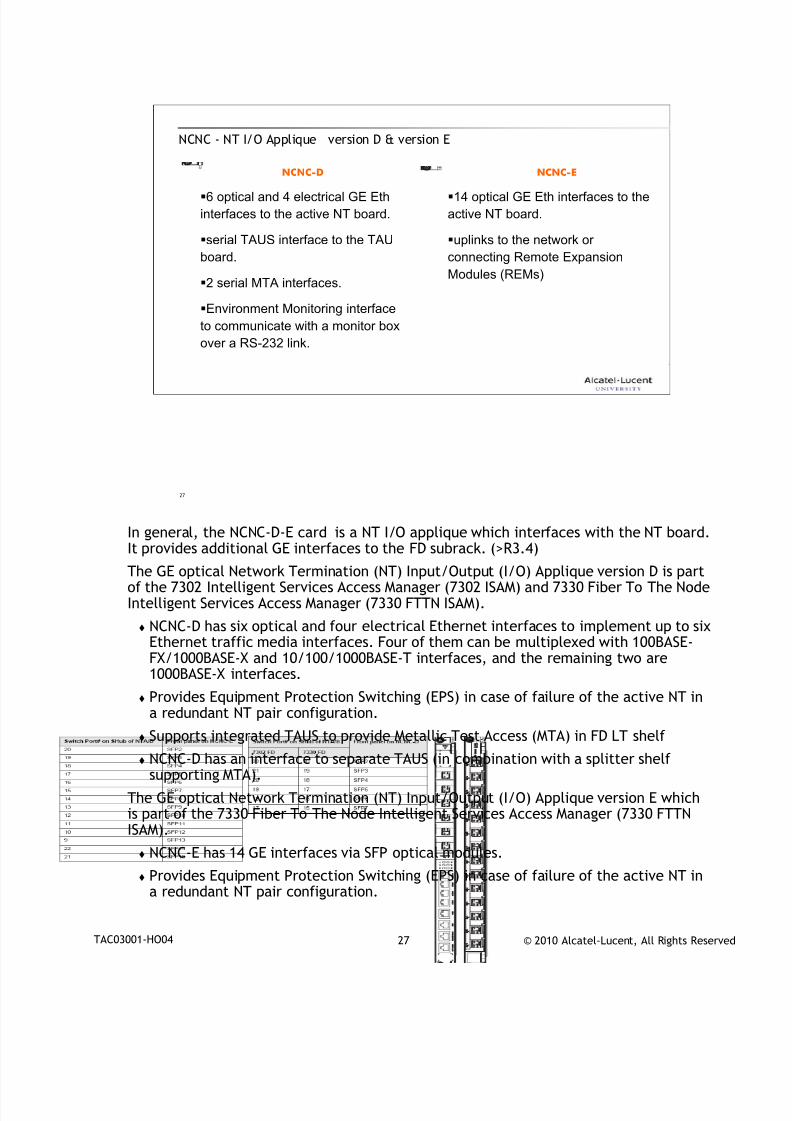
NCNC - NT I/O Applique version D & version E
6 optical and 4 electrical GE Eth
interfaces to the active NT board.
serial TAUS interface to the TAU
board.
2 serial MTA interfaces.
Environment Monitoring interface
to communicate with a monitor box
over a RS-232 link.
NCNC-D NCNC-E
14 optical GE Eth interfaces to the
active NT board.
uplinks to the network or
connecting Remote Expansion
Modules (REMs)
In general, the NCNC-D-E card is a NT I/O applique which interfaces with the NT board.
It provides additional GE interfaces to the FD subrack. (>R3.4)
The GE optical Network Termination (NT) Input/Output (I/O) Applique version D is partof the 7302 Intelligent Services Access Manager (7302 ISAM) and 7330 Fiber To The NodeIntelligent Services Access Manager (7330 FTTN ISAM).
NCNC-D has six optical and four electrical Ethernet interfaces to implement up to sixEthernet traffic media interfaces. Four of them can be multiplexed with 100BASE-FX/1000BASE-X and 10/100/1000BASE-T interfaces, and the remaining two are1000BASE-X interfaces.
Provides Equipment Protection Switching (EPS) in case of failure of the active NT ina redundant NT pair configuration.
Supports integrated TAUS to provide Metallic Test Access (MTA) in FD LT shelf
NCNC-D has an interface to separate TAUS (in combination with a splitter shelfsupporting MTA).
The GE optical Network Termination (NT) Input/Output (I/O) Applique version E whichis part of the 7330 Fiber To The Node Intelligent Services Access Manager (7330 FTTNISAM).
NCNC-E has 14 GE interfaces via SFP optical modules.
Provides Equipment Protection Switching (EPS) in case of failure of the active NT ina redundant NT pair configuration.
7/18/2019 Alu - A7302 Isam Fttu Operator Gpon Nant-e_ce-PDF
http://slidepdf.com/reader/full/alu-a7302-isam-fttu-operator-gpon-nant-ece-pdf 37/432
© 2010 Alcatel-Lucent, All Rights ReservedTAC03001-HO04 28
28
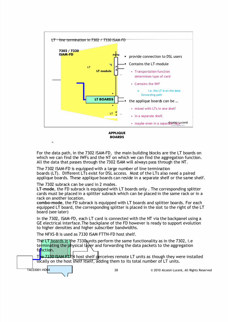
LT – line termination in 7302 / 7330 ISAM-FD
provide connection to DSL users
Contains the LT-module
• Transportation function
determines type of card
• Contains the IWF
o i.e. the LT is on the data
forwarding path
the applique boards can be …
• mixed with LTs in one shelf
• in a separate shelf,
• maybe even in a separate rack
LT
.
.
.
…
…P
S
P
S
PSTN7302 / 7330ISAM-FD
LT BOARDS
APPLIQUEBOARDS
LT module
LT
For the data path, in the 7302 ISAM-FD, the main building blocks are the LT boards on
which we can find the IWFs and the NT on which we can find the aggregation function.All the data that passes through the 7302 ISAM will always pass through the NT.
The 7302 ISAM-FD is equipped with a large number of line terminationboards (LT). Different LTs exist for DSL access. Most of the LTs also need a pairedapplique boards. These applique boards can reside in a separate shelf or the same shelf.
The 7302 subrack can be used in 2 modes.LT-mode, the FD subrack is equipped with LT boards only . The corresponding splittercards must be placed in a splitter subrack which can be placed in the same rack or in arack on another location.combo-mode, the FD subrack is equipped with LT boards and splitter boards. For each
equipped LT board, the corresponding splitter is placed in the slot to the right of the LTboard (see later)
In the 7302, ISAM-FD, each LT card is connected with the NT via the backpanel using aGE electrical interface.The backplane of the FD however is ready to support evolutionto higher densities and higher subscriber bandwidths.
The NFXS-B is used as 7330 ISAM FTTN-FD host shelf.
The LT boards in the 7330 units perform the same functionality as in the 7302, i.eterminating the physical layer and forwarding the data packets to the aggregationfunction.
The 7330 ISAM FTTN host shelf perceives remote LT units as though they were installed
locally on the host shelf itself, adding them to its total number of LT units.
7/18/2019 Alu - A7302 Isam Fttu Operator Gpon Nant-e_ce-PDF
http://slidepdf.com/reader/full/alu-a7302-isam-fttu-operator-gpon-nant-ece-pdf 38/432
© 2010 Alcatel-Lucent, All Rights ReservedTAC03001-HO04 29
29
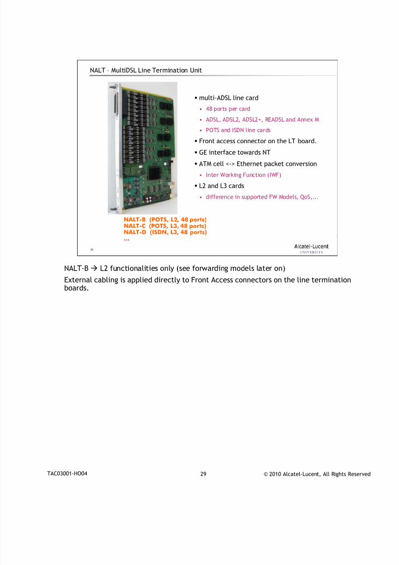
NALT – MultiDSL Line Termination Unit
multi-ADSL line card
• 48 ports per card
• ADSL, ADSL2, ADSL2+, READSL and Annex M
• POTS and ISDN line cards
Front access connector on the LT board.
GE interface towards NT
ATM cell <-> Ethernet packet conversion
• Inter Working Function (IWF)
L2 and L3 cards
• difference in supported FW Models, QoS,...
NALT-B (POTS, L2, 48 ports)NALT-C (POTS, L3, 48 ports)NALT-D (ISDN, L3, 48 ports)…
NALT-B L2 functionalities only (see forwarding models later on)
External cabling is applied directly to Front Access connectors on the line terminationboards.
7/18/2019 Alu - A7302 Isam Fttu Operator Gpon Nant-e_ce-PDF
http://slidepdf.com/reader/full/alu-a7302-isam-fttu-operator-gpon-nant-ece-pdf 39/432
© 2010 Alcatel-Lucent, All Rights ReservedTAC03001-HO04 30
30
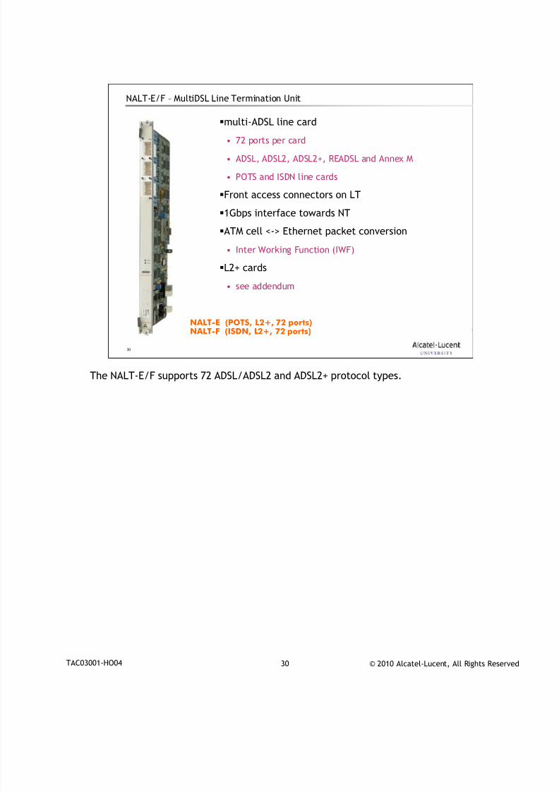
NALT-E/F – MultiDSL Line Termination Unit
multi-ADSL line card
• 72 ports per card
• ADSL, ADSL2, ADSL2+, READSL and Annex M
• POTS and ISDN line cards
Front access connectors on LT
1Gbps interface towards NT
ATM cell <-> Ethernet packet conversion
• Inter Working Function (IWF)
L2+ cards
• see addendum
NALT-E (POTS, L2+, 72 ports)NALT-F (ISDN, L2+, 72 ports)
The NALT-E/F supports 72 ADSL/ADSL2 and ADSL2+ protocol types.
7/18/2019 Alu - A7302 Isam Fttu Operator Gpon Nant-e_ce-PDF
http://slidepdf.com/reader/full/alu-a7302-isam-fttu-operator-gpon-nant-ece-pdf 40/432
© 2010 Alcatel-Lucent, All Rights ReservedTAC03001-HO04 31
31
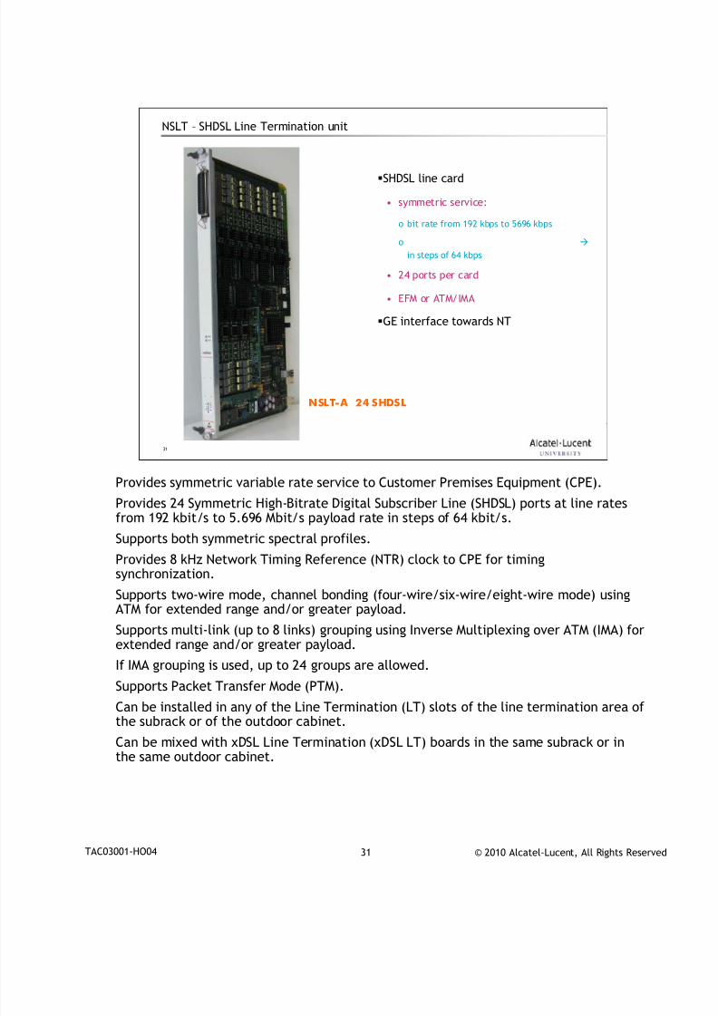
NSLT – SHDSL Line Termination unit
SHDSL line card
• symmetric service:
o bit rate from 192 kbps to 5696 kbps
o
in steps of 64 kbps
• 24 ports per card
• EFM or ATM/IMA
GE interface towards NT
NSLT-A 24 SHDSL
Provides symmetric variable rate service to Customer Premises Equipment (CPE).
Provides 24 Symmetric High-Bitrate Digital Subscriber Line (SHDSL) ports at line ratesfrom 192 kbit/s to 5.696 Mbit/s payload rate in steps of 64 kbit/s.
Supports both symmetric spectral profiles.
Provides 8 kHz Network Timing Reference (NTR) clock to CPE for timingsynchronization.
Supports two-wire mode, channel bonding (four-wire/six-wire/eight-wire mode) usingATM for extended range and/or greater payload.
Supports multi-link (up to 8 links) grouping using Inverse Multiplexing over ATM (IMA) forextended range and/or greater payload.
If IMA grouping is used, up to 24 groups are allowed.
Supports Packet Transfer Mode (PTM).
Can be installed in any of the Line Termination (LT) slots of the line termination area ofthe subrack or of the outdoor cabinet.
Can be mixed with xDSL Line Termination (xDSL LT) boards in the same subrack or inthe same outdoor cabinet.
7/18/2019 Alu - A7302 Isam Fttu Operator Gpon Nant-e_ce-PDF
http://slidepdf.com/reader/full/alu-a7302-isam-fttu-operator-gpon-nant-ece-pdf 41/432
© 2010 Alcatel-Lucent, All Rights ReservedTAC03001-HO04 32
32
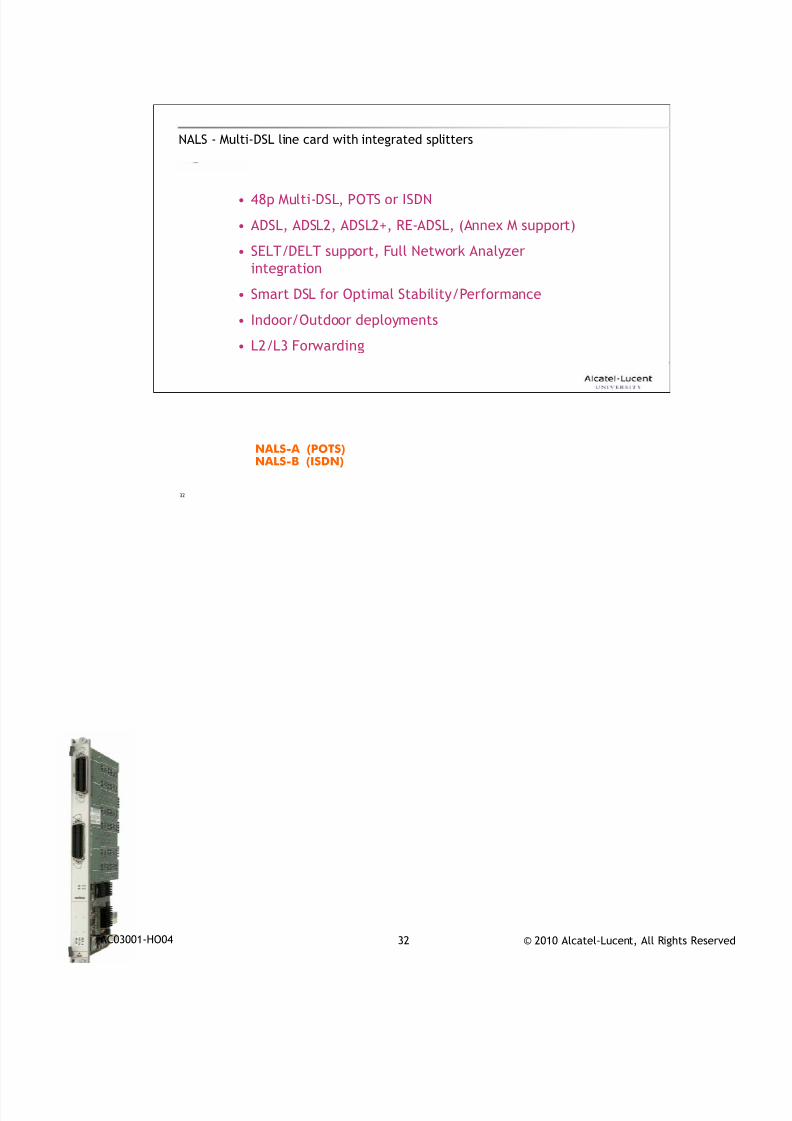
NALS - Multi-DSL line card with integrated splitters
• 48p Multi-DSL, POTS or ISDN
• ADSL, ADSL2, ADSL2+, RE-ADSL, (Annex M support)
• SELT/DELT support, Full Network Analyzer
integration
• Smart DSL for Optimal Stability/Performance
• Indoor/Outdoor deployments
• L2/L3 Forwarding
NALS-A (POTS)NALS-B (ISDN)
7/18/2019 Alu - A7302 Isam Fttu Operator Gpon Nant-e_ce-PDF
http://slidepdf.com/reader/full/alu-a7302-isam-fttu-operator-gpon-nant-ece-pdf 42/432
© 2010 Alcatel-Lucent, All Rights ReservedTAC03001-HO04 33
33
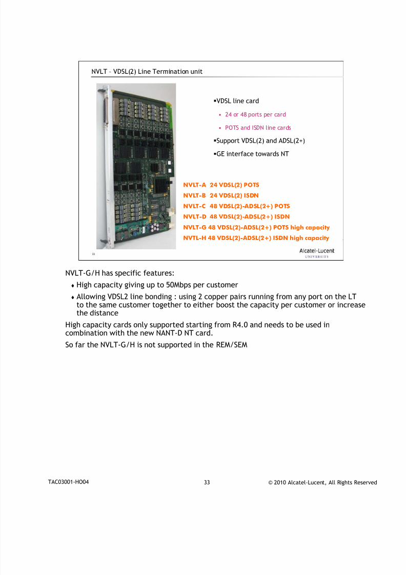
NVLT – VDSL(2) Line Termination unit
VDSL line card
• 24 or 48 ports per card
• POTS and ISDN line cards
Support VDSL(2) and ADSL(2+)
GE interface towards NT
NVLT-A 24 VDSL(2) POTSNVLT-B 24 VDSL(2) ISDN
NVLT-C 48 VDSL(2)-ADSL(2+) POTS
NVLT-D 48 VDSL(2)-ADSL(2+) ISDN
NVLT-G 48 VDSL(2)-ADSL(2+) POTS high capacity
NVTL-H 48 VDSL(2)-ADSL(2+) ISDN high capacity
NVLT-G/H has specific features:
High capacity giving up to 50Mbps per customer
Allowing VDSL2 line bonding : using 2 copper pairs running from any port on the LTto the same customer together to either boost the capacity per customer or increasethe distance
High capacity cards only supported starting from R4.0 and needs to be used incombination with the new NANT-D NT card.
So far the NVLT-G/H is not supported in the REM/SEM
7/18/2019 Alu - A7302 Isam Fttu Operator Gpon Nant-e_ce-PDF
http://slidepdf.com/reader/full/alu-a7302-isam-fttu-operator-gpon-nant-ece-pdf 43/432
© 2010 Alcatel-Lucent, All Rights ReservedTAC03001-HO04 34
34
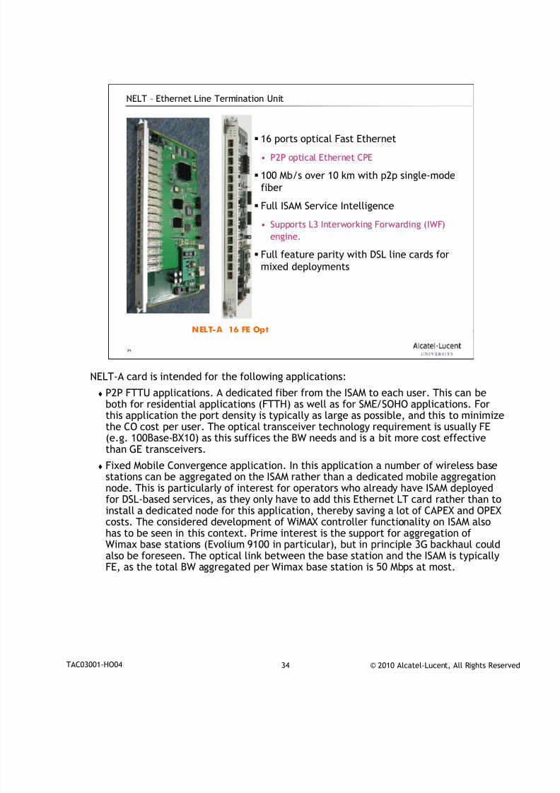
NELT – Ethernet Line Termination Unit
16 ports optical Fast Ethernet
• P2P optical Ethernet CPE
100 Mb/s over 10 km with p2p single-mode
fiber
Full ISAM Service Intelligence
• Supports L3 Interworking Forwarding (IWF)
engine.
Full feature parity with DSL line cards formixed deployments
NELT-A 16 FE Opt
NELT-A card is intended for the following applications:
P2P FTTU applications. A dedicated fiber from the ISAM to each user. This can beboth for residential applications (FTTH) as well as for SME/SOHO applications. Forthis application the port density is typically as large as possible, and this to minimizethe CO cost per user. The optical transceiver technology requirement is usually FE(e.g. 100Base-BX10) as this suffices the BW needs and is a bit more cost effectivethan GE transceivers.
Fixed Mobile Convergence application. In this application a number of wireless basestations can be aggregated on the ISAM rather than a dedicated mobile aggregationnode. This is particularly of interest for operators who already have ISAM deployedfor DSL-based services, as they only have to add this Ethernet LT card rather than to
install a dedicated node for this application, thereby saving a lot of CAPEX and OPEXcosts. The considered development of WiMAX controller functionality on ISAM alsohas to be seen in this context. Prime interest is the support for aggregation ofWimax base stations (Evolium 9100 in particular), but in principle 3G backhaul couldalso be foreseen. The optical link between the base station and the ISAM is typicallyFE, as the total BW aggregated per Wimax base station is 50 Mbps at most.
7/18/2019 Alu - A7302 Isam Fttu Operator Gpon Nant-e_ce-PDF
http://slidepdf.com/reader/full/alu-a7302-isam-fttu-operator-gpon-nant-ece-pdf 44/432
© 2010 Alcatel-Lucent, All Rights ReservedTAC03001-HO04 35
35
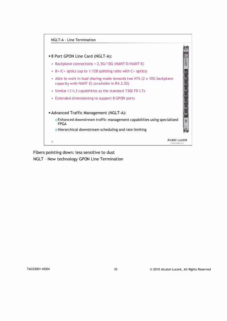
NGLT-A - Line Termination
8 Port GPON Line Card (NGLT-A):
• Backplane connections = 2,5G/10G (NANT-D/NANT-E)
• B+/C+ optics (up to 1:128 splitting ratio with C+ optics)
• Able to work in load sharing mode towards two NTs (2 x 10G backplane
capacity with NANT-E) (available in R4.2.02)
• Similar L2/L3 capabilities as the standard 7302 FD LTs
• Extended dimensioning to support 8 GPON ports
Advanced Traffic Management (NGLT-A):
o Enhanced downstream traffic management capabilities using specializedFPGA
o Hierarchical downstream scheduling and rate limiting
Fibers pointing down: less sensitive to dust
NGLT – New technology GPON Line Termination
7/18/2019 Alu - A7302 Isam Fttu Operator Gpon Nant-e_ce-PDF
http://slidepdf.com/reader/full/alu-a7302-isam-fttu-operator-gpon-nant-ece-pdf 45/432
© 2010 Alcatel-Lucent, All Rights ReservedTAC03001-HO04 36
36
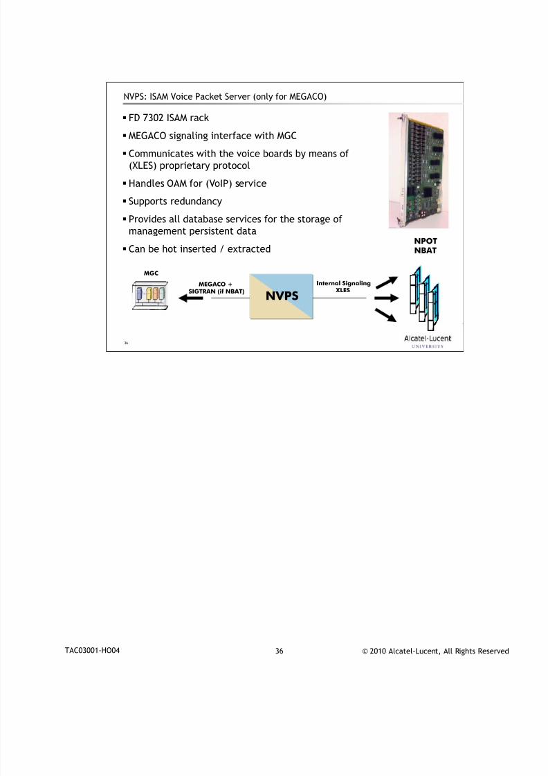
NVPS: ISAM Voice Packet Server (only for MEGACO)
FD 7302 ISAM rack
MEGACO signaling interface with MGC
Communicates with the voice boards by means of
(XLES) proprietary protocol
Handles OAM for (VoIP) service
Supports redundancy
Provides all database services for the storage of
management persistent data
Can be hot inserted / extracted
Internal Signaling XLES
MEGACO +SIGTRAN (if NBAT)
NPOT
NVPS
MGC
NBAT
7/18/2019 Alu - A7302 Isam Fttu Operator Gpon Nant-e_ce-PDF
http://slidepdf.com/reader/full/alu-a7302-isam-fttu-operator-gpon-nant-ece-pdf 46/432
© 2010 Alcatel-Lucent, All Rights ReservedTAC03001-HO04 37
37
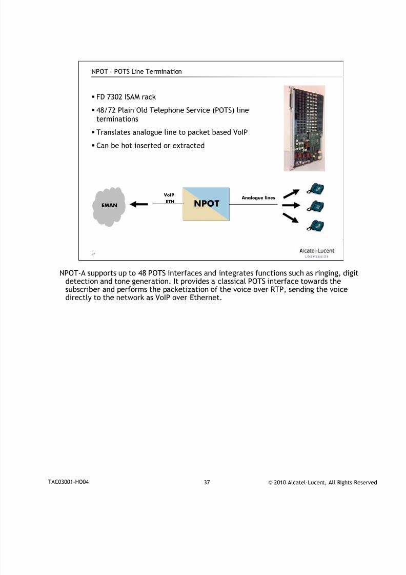
NPOT – POTS Line Termination
FD 7302 ISAM rack
48/72 Plain Old Telephone Service (POTS) line
terminations
Translates analogue line to packet based VoIP
Can be hot inserted or extracted
Analogue lines VoIP
NPOTETHEMAN
NPOT-A supports up to 48 POTS interfaces and integrates functions such as ringing, digit
detection and tone generation. It provides a classical POTS interface towards thesubscriber and performs the packetization of the voice over RTP, sending the voicedirectly to the network as VoIP over Ethernet.
7/18/2019 Alu - A7302 Isam Fttu Operator Gpon Nant-e_ce-PDF
http://slidepdf.com/reader/full/alu-a7302-isam-fttu-operator-gpon-nant-ece-pdf 47/432
© 2010 Alcatel-Lucent, All Rights ReservedTAC03001-HO04 38
38
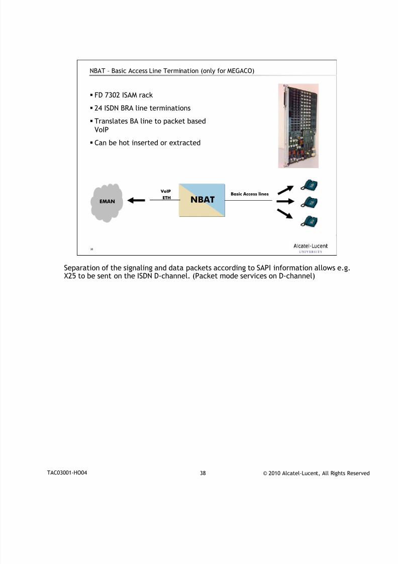
NBAT – Basic Access Line Termination (only for MEGACO)
Basic Access lines VoIP
NBATETHEMAN
FD 7302 ISAM rack
24 ISDN BRA line terminations
Translates BA line to packet based
VoIP
Can be hot inserted or extracted
Separation of the signaling and data packets according to SAPI information allows e.g.
X25 to be sent on the ISDN D-channel. (Packet mode services on D-channel)
7/18/2019 Alu - A7302 Isam Fttu Operator Gpon Nant-e_ce-PDF
http://slidepdf.com/reader/full/alu-a7302-isam-fttu-operator-gpon-nant-ece-pdf 48/432
© 2010 Alcatel-Lucent, All Rights ReservedTAC03001-HO04 39
39
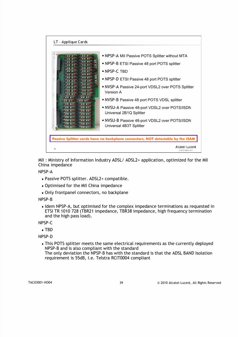
LT – Applique Cards
NPSP-A MII Passive POTS Splitter without MTA
NPSP-B ETSI Passive 48 port POTS splitter
NPSP-C TBD
NPSP-D ETSI Passive 48 port POTS splitter
NVSP-A Passive 24-port VDSL2 over POTS Splitter
Version A
NVSP-B Passive 48 port POTS VDSL splitter
NVSU-A Passive 48-port VDSL2 over POTS/ISDNUniversal 2B1Q Splitter
NVSU-B Passive 48-port VDSL2 over POTS/ISDN
Universal 4B3T Splitter
Passive Splitter cards have no backplane connectors, NOT detectable by the ISAM
MII : Ministry of Information Industry ADSL/ ADSL2+ application, optimized for the MII
China impedance
NPSP-A
Passive POTS splitter. ADSL2+ compatible.
Optimised for the MII China impedance
Only frontpanel connectors, no backplane
NPSP-B
Idem NPSP-A, but optimised for the complex impedance terminations as requested inETSI TR 1010 728 (TBR21 impedance, TBR38 impedance, high frequency terminationand the high pass load).
NPSP-C
TBD
NPSP-D
This POTS splitter meets the same electrical requirements as the currently deployedNPSP-B and is also compliant with the standardThe only deviation the NPSP-B has with the standard is that the ADSL BAND Isolationrequirement is 55dB, I.e. Telstra RCIT0004 compliant
7/18/2019 Alu - A7302 Isam Fttu Operator Gpon Nant-e_ce-PDF
http://slidepdf.com/reader/full/alu-a7302-isam-fttu-operator-gpon-nant-ece-pdf 49/432
© 2010 Alcatel-Lucent, All Rights ReservedTAC03001-HO04 40
40
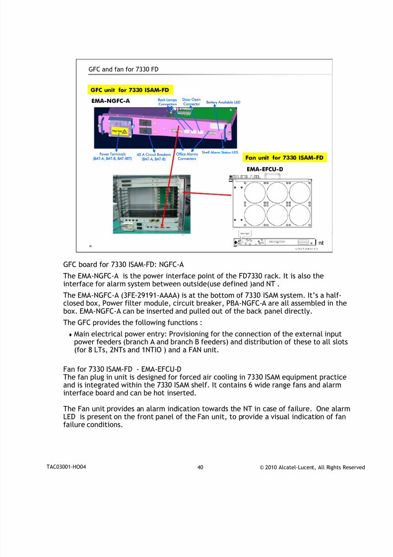
GFC and fan for 7330 FD
Power Terminals(BAT-A, BAT-B, BAT-RET)
40 A Circuit Breakers(BAT-A, BAT-B)
Battery Available LED
Shelf Alarm Status LEDOffice AlarmsConnectors
Rack LampsConnectors
Door OpenConnector
Power Terminals(BAT-A, BAT-B, BAT-RET)
40 A Circuit Breakers(BAT-A, BAT-B)
Battery Available LED
Shelf Alarm Status LEDOffice AlarmsConnectors
Rack LampsConnectors
Door OpenConnector
GFC unit for 7330 ISAM-FD
Fan unit for 7330 ISAM-FD
EMA-NGFC-A
EMA-EFCU-D
GFC board for 7330 ISAM-FD: NGFC-A
The EMA-NGFC-A is the power interface point of the FD7330 rack. It is also theinterface for alarm system between outside(use defined )and NT .
The EMA-NGFC-A (3FE-29191-AAAA) is at the bottom of 7330 ISAM system. It’s a half-closed box, Power filter module, circuit breaker, PBA-NGFC-A are all assembled in thebox. EMA-NGFC-A can be inserted and pulled out of the back panel directly.
The GFC provides the following functions :
Main electrical power entry: Provisioning for the connection of the external inputpower feeders (branch A and branch B feeders) and distribution of these to all slots(for 8 LTs, 2NTs and 1NTIO ) and a FAN unit.
Fan for 7330 ISAM-FD - EMA-EFCU-DThe fan plug in unit is designed for forced air cooling in 7330 ISAM equipment practiceand is integrated within the 7330 ISAM shelf. It contains 6 wide range fans and alarminterface board and can be hot inserted.
The Fan unit provides an alarm indication towards the NT in case of failure. One alarmLED is present on the front panel of the Fan unit, to provide a visual indication of fanfailure conditions.
7/18/2019 Alu - A7302 Isam Fttu Operator Gpon Nant-e_ce-PDF
http://slidepdf.com/reader/full/alu-a7302-isam-fttu-operator-gpon-nant-ece-pdf 50/432
© 2010 Alcatel-Lucent, All Rights ReservedTAC03001-HO04 41
41
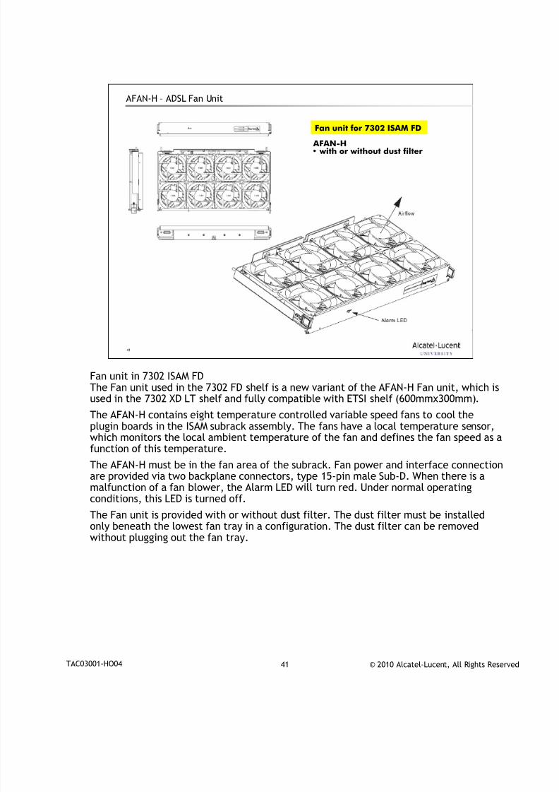
AFAN-H – ADSL Fan Unit
Fan unit for 7302 ISAM FD
AFAN-H• with or without dust filter
Fan unit in 7302 ISAM FD
The Fan unit used in the 7302 FD shelf is a new variant of the AFAN-H Fan unit, which isused in the 7302 XD LT shelf and fully compatible with ETSI shelf (600mmx300mm).
The AFAN-H contains eight temperature controlled variable speed fans to cool theplugin boards in the ISAM subrack assembly. The fans have a local temperature sensor,which monitors the local ambient temperature of the fan and defines the fan speed as afunction of this temperature.
The AFAN-H must be in the fan area of the subrack. Fan power and interface connectionare provided via two backplane connectors, type 15-pin male Sub-D. When there is amalfunction of a fan blower, the Alarm LED will turn red. Under normal operatingconditions, this LED is turned off.
The Fan unit is provided with or without dust filter. The dust filter must be installedonly beneath the lowest fan tray in a configuration. The dust filter can be removedwithout plugging out the fan tray.
7/18/2019 Alu - A7302 Isam Fttu Operator Gpon Nant-e_ce-PDF
http://slidepdf.com/reader/full/alu-a7302-isam-fttu-operator-gpon-nant-ece-pdf 51/432
© 2010 Alcatel-Lucent, All Rights ReservedTAC03001-HO04 42
42
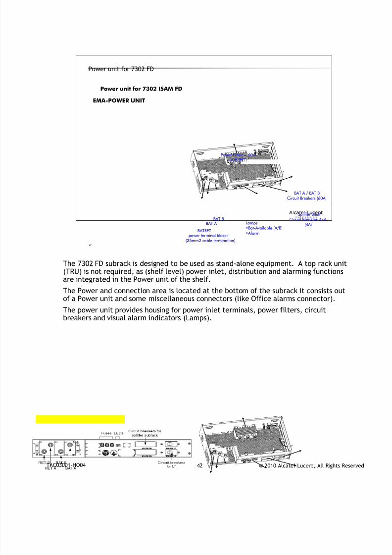
Power unit for 7302 FD
Power Filters – 60A (A/B/RET)
BAT A / BAT B
Circuit Breakers (60A)
Splitter Shelf
Circuit Breakers A/B(4A)BAT A
BAT B
BATRETpower terminal blocks
(35mm2 cable termination)
Lamps•Bat-Available (A/B)
•Alarm
Power Filters – 60A (A/B/RET)
BAT A / BAT B
Circuit Breakers (60A)
Splitter Shelf
Circuit Breakers A/B(4A)BAT A
BAT B
BATRETpower terminal blocks
(35mm2 cable termination)
Lamps•Bat-Available (A/B)
•Alarm
Power unit for 7302 ISAM FD
EMA-POWER UNIT
The 7302 FD subrack is designed to be used as stand-alone equipment. A top rack unit
(TRU) is not required, as (shelf level) power inlet, distribution and alarming functionsare integrated in the Power unit of the shelf.
The Power and connection area is located at the bottom of the subrack it consists outof a Power unit and some miscellaneous connectors (like Office alarms connector).
The power unit provides housing for power inlet terminals, power filters, circuitbreakers and visual alarm indicators (Lamps).

7/18/2019 Alu - A7302 Isam Fttu Operator Gpon Nant-e_ce-PDF
http://slidepdf.com/reader/full/alu-a7302-isam-fttu-operator-gpon-nant-ece-pdf 52/432
© 2010 Alcatel-Lucent, All Rights ReservedTAC03001-HO04 43
43
www.alcatel-lucent.comwww.alcatel-lucent.com

7/18/2019 Alu - A7302 Isam Fttu Operator Gpon Nant-e_ce-PDF
http://slidepdf.com/reader/full/alu-a7302-isam-fttu-operator-gpon-nant-ece-pdf 53/432
© 2010 Alcatel-Lucent, All Rights ReservedDocument Number | Document Title 1
NANT-E : High Cap NT
During class please switch off your mobile, pager or other that may interrupt.

7/18/2019 Alu - A7302 Isam Fttu Operator Gpon Nant-e_ce-PDF
http://slidepdf.com/reader/full/alu-a7302-isam-fttu-operator-gpon-nant-ece-pdf 54/432
© 2010 Alcatel-Lucent, All Rights ReservedDocument Number | Document Title 2
2
Objective
Upon completion of the module you will be able to
Explain why we need a new NT board
Explain for yourself the essential properties of the NANT-E
Give an overview of the different architectural parts of the NANT-E
board
7/18/2019 Alu - A7302 Isam Fttu Operator Gpon Nant-e_ce-PDF
http://slidepdf.com/reader/full/alu-a7302-isam-fttu-operator-gpon-nant-ece-pdf 55/432
© 2010 Alcatel-Lucent, All Rights ReservedDocument Number | Document Title 3
3
Table of Contents
1.NT Positioning / Evolution
2.NANT-E Architecture
3.Access Network Topologies

7/18/2019 Alu - A7302 Isam Fttu Operator Gpon Nant-e_ce-PDF
http://slidepdf.com/reader/full/alu-a7302-isam-fttu-operator-gpon-nant-ece-pdf 56/432
© 2010 Alcatel-Lucent, All Rights ReservedDocument Number | Document Title 4
4
NT Positioning / Evolution1
7/18/2019 Alu - A7302 Isam Fttu Operator Gpon Nant-e_ce-PDF
http://slidepdf.com/reader/full/alu-a7302-isam-fttu-operator-gpon-nant-ece-pdf 57/432
© 2010 Alcatel-Lucent, All Rights ReservedDocument Number | Document Title 5
5
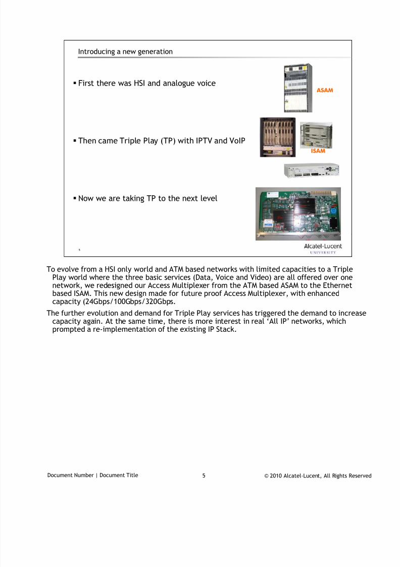
Introducing a new generation
First there was HSI and analogue voice
Then came Triple Play (TP) with IPTV and VoIP
Now we are taking TP to the next level
ISAM
ASAM
To evolve from a HSI only world and ATM based networks with limited capacities to a Triple
Play world where the three basic services (Data, Voice and Video) are all offered over onenetwork, we redesigned our Access Multiplexer from the ATM based ASAM to the Ethernetbased ISAM. This new design made for future proof Access Multiplexer, with enhancedcapacity (24Gbps/100Gbps/320Gbps.
The further evolution and demand for Triple Play services has triggered the demand to increasecapacity again. At the same time, there is more interest in real ‘All IP’ networks, whichprompted a re-implementation of the existing IP Stack.
7/18/2019 Alu - A7302 Isam Fttu Operator Gpon Nant-e_ce-PDF
http://slidepdf.com/reader/full/alu-a7302-isam-fttu-operator-gpon-nant-ece-pdf 58/432
© 2010 Alcatel-Lucent, All Rights ReservedDocument Number | Document Title 6
6
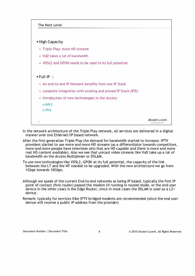
The Next Level
High Capacity
• Triple Play: more HD streams
• VoD takes a lot of bandwidth
• VDSL2 and GPON needs to be used to its full potential
Full IP :
• An end-to-end IP Network benefits from one IP Stack
• complete integration with existing and proved IP Stack (IPD)
• Introduction of new technologies in the Access:
o MPLS
o IPv6
In the network architecture of the Triple Play network, all services are delivered in a digital
manner over one Ethernet/IP based network.
After the first generation Triple Play the demand for bandwidth started to increase. IPTVproviders started to use more and more HD streams (as a differentiator towards competitors,more and more people have television sets that are HD capable and there is more and morereal HD content available). Also we see that unicast video streams like VoD take up a lot ofbandwidth on the Access Multiplexer or DSLAM.
To use new technologies like VDSL2, GPON at its full potential, the capacity of the linkbetween the LT and the NT needed to be upgraded. With the new architecture we go from1Gbps towards 10Gbps.
Although we speak of the current End-to-end networks as being IP based, typically the first IPpoint of contact (first router) passed the modem (if running in routed mode, or the end userdevice in the other case) is the Edge Router, since in most cases the DSLAM is used as a L2+device.
Remark: typically for services llike IPTV bridged modems are recommended (since the end userdevice will receive a public IP address from the provider)
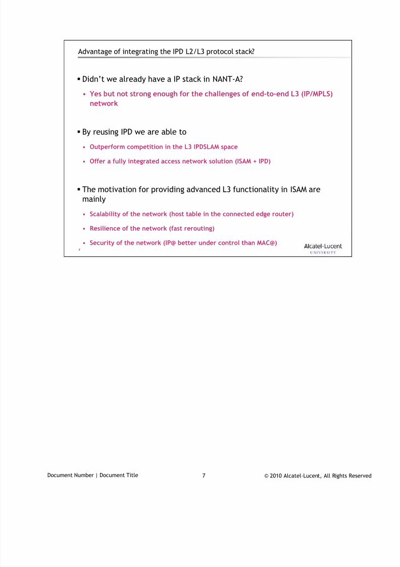
7/18/2019 Alu - A7302 Isam Fttu Operator Gpon Nant-e_ce-PDF
http://slidepdf.com/reader/full/alu-a7302-isam-fttu-operator-gpon-nant-ece-pdf 59/432
© 2010 Alcatel-Lucent, All Rights ReservedDocument Number | Document Title 7
7
Advantage of integrating the IPD L2/L3 protocol stack?
Didn’t we already have a IP stack in NANT-A?
• Yes but not strong enough for the challenges of end-to-end L3 (IP/MPLS)network
By reusing IPD we are able to
• Outperform competition in the L3 IPDSLAM space
• Offer a fully integrated access network solution (ISAM + IPD)
The motivation for providing advanced L3 functionality in ISAM are
mainly
• Scalability of the network (host table in the connected edge router)
• Resilience of the network (fast rerouting)
• Security of the network (IP@ better under control than MAC@)
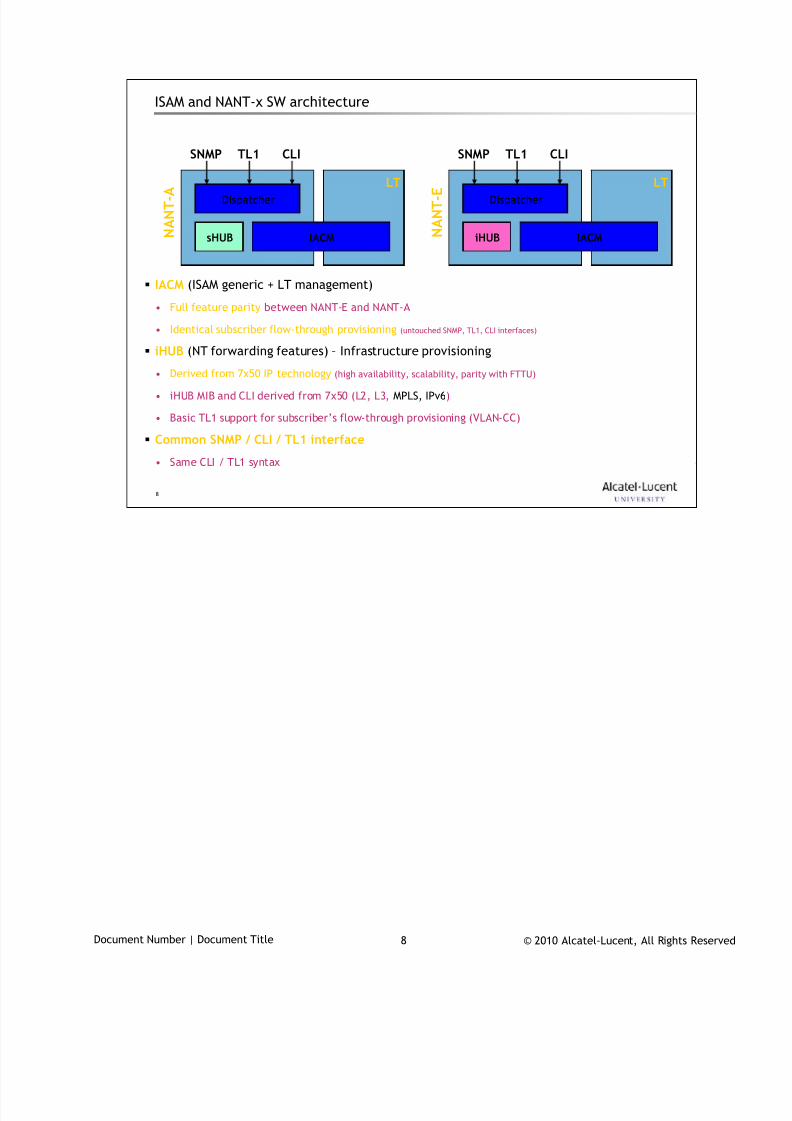
7/18/2019 Alu - A7302 Isam Fttu Operator Gpon Nant-e_ce-PDF
http://slidepdf.com/reader/full/alu-a7302-isam-fttu-operator-gpon-nant-ece-pdf 60/432
© 2010 Alcatel-Lucent, All Rights ReservedDocument Number | Document Title 8
8
ISAM and NANT-x SW architecture
IACM (ISAM generic + LT management)
• Full feature parity between NANT-E and NANT-A
• Identical subscriber flow-through provisioning (untouched SNMP, TL1, CLI interfaces)
iHUB (NT forwarding features) – Infrastructure provisioning
• Derived from 7x50 IP technology (high availability, scalability, parity with FTTU)
• iHUB MIB and CLI derived from 7x50 (L2, L3, MPLS, IPv6)
• Basic TL1 support for subscriber’s flow-through provisioning (VLAN-CC)
Common SNMP / CLI / TL1 interface
• Same CLI / TL1 syntax
Dispatcher
iHUB IACM N A N T - E LT
SNMP TL1 CLI
Dispatcher
sHUB IACM N A N T - A LT
SNMP TL1 CLI
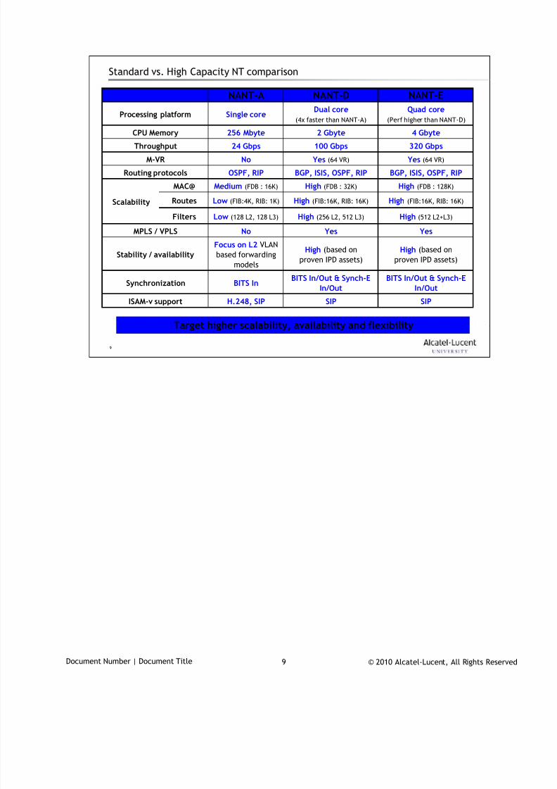
7/18/2019 Alu - A7302 Isam Fttu Operator Gpon Nant-e_ce-PDF
http://slidepdf.com/reader/full/alu-a7302-isam-fttu-operator-gpon-nant-ece-pdf 61/432
© 2010 Alcatel-Lucent, All Rights ReservedDocument Number | Document Title 9
9
Standard vs. High Capacity NT comparison
Target higher scalability, availability and flexibility
SIP
BITS In/Out & Synch-E
In/Out
High (based on
proven IPD assets)
Yes
High (512 L2+L3)
High (FIB:16K, RIB: 16K)
High (FDB : 128K)
BGP, ISIS, OSPF, RIP
Yes (64 VR)
320 Gbps
4 Gbyte
Quad core
(Perf higher than NANT-D)
NANT-E
SIPH.248, SIPISAM-v support
MAC@ High (FDB : 32K)Medium (FDB : 16K)
BGP, ISIS, OSPF, RIPOSPF, RIPRouting protocols
BITS In/Out & Synch-E
In/OutBITS InSynchronization
100 Gbps24 GbpsThroughput
Yes (64 VR)NoM-VR
YesNoMPLS / VPLS
Dual core
(4x faster than NANT-A)Single coreProcessing platform
2 Gbyte256 MbyteCPU Memory
Filters
Routes
NANT-DNANT-A
High (based on
proven IPD assets)
Focus on L2 VLAN
based forwardingmodels
Stability / availability
High (256 L2, 512 L3)Low (128 L2, 128 L3)
High (FIB:16K, RIB: 16K)Low (FIB:4K, RIB: 1K)Scalability

7/18/2019 Alu - A7302 Isam Fttu Operator Gpon Nant-e_ce-PDF
http://slidepdf.com/reader/full/alu-a7302-isam-fttu-operator-gpon-nant-ece-pdf 62/432
© 2010 Alcatel-Lucent, All Rights ReservedDocument Number | Document Title 10
10
NANT-E Architecture2

7/18/2019 Alu - A7302 Isam Fttu Operator Gpon Nant-e_ce-PDF
http://slidepdf.com/reader/full/alu-a7302-isam-fttu-operator-gpon-nant-ece-pdf 63/432
© 2010 Alcatel-Lucent, All Rights ReservedDocument Number | Document Title 11
11
NANT-E key requirements
The NANT-E board …
• … is HiCap-ready i.e. :
– Interoperable with all 2.5Gbps and 10Gbps HiCap LT boards
– Support for 10Gbps uplink
– 320Gbps switching capacity
• … allows the integration of the IPD L2/L3 protocol stack
• … allows multiple synchronization architectures:
– Sync Eth In/Out
– (dual) BITS In/Out
• … is supported for 7302 and 7330 FD ISAM
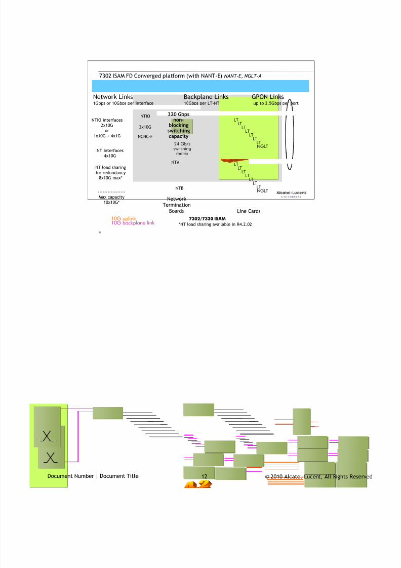
7/18/2019 Alu - A7302 Isam Fttu Operator Gpon Nant-e_ce-PDF
http://slidepdf.com/reader/full/alu-a7302-isam-fttu-operator-gpon-nant-ece-pdf 64/432
© 2010 Alcatel-Lucent, All Rights ReservedDocument Number | Document Title 12
12
7302 ISAM FD Converged platform (with NANT-E) NANT-E, NGLT-A
Line Cards
7302/7330 ISAM
Network Links Backplane Links GPON Links1Gbps or 10Gbps per interface 10Gbps per LT-NT up to 2.5Gbps per port
24 Gb/sswitching
matrix
Network
Termination
Boards
NTB
NTA
LTLT
LTLT
LTLT
LTNGLT
LTLT
LTLT
LT
LTLTNGLT
NTIO
2x10G
NCNC-F
10G uplink10G backplane link
NTIO interfaces
2x10G
or
1x10G + 4x1G
320 Gbpsnon-
blockingswitchingcapacity
NT interfaces
4x10G
NT load sharing
for redundancy
8x10G max*
-----------------
Max capacity
10x10G*
*NT load sharing available in R4.2.02

7/18/2019 Alu - A7302 Isam Fttu Operator Gpon Nant-e_ce-PDF
http://slidepdf.com/reader/full/alu-a7302-isam-fttu-operator-gpon-nant-ece-pdf 65/432
© 2010 Alcatel-Lucent, All Rights ReservedDocument Number | Document Title 1313
13
ISAM NANT-E 320 Gbps Controller
High capacity NT for fiber deploymentsFirst AE processor on the market – ready for future application intelligence in AN
• Switching capacity: 320 Gb/s, 640 Gb/s in AA mode
• Active-active mode and loadsharing (20Gbps per LT) and redundancy
• Uplinks: 4 x 1G/2,5G/10G
• BITS and Sync-E clock recovery, high stability clock
• Advanced L3/MPLS forwarding capabilities
• Virtual routers: Multiple
• Enhanced routing protocols: OSPF/RIP/IS-IS/BGP
• Powerful Embedded Application Enablement (AE) processor• Industrial hardened for outdoor deployments
NANT-E Key Features
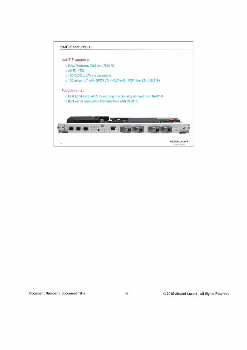
7/18/2019 Alu - A7302 Isam Fttu Operator Gpon Nant-e_ce-PDF
http://slidepdf.com/reader/full/alu-a7302-isam-fttu-operator-gpon-nant-ece-pdf 66/432
© 2010 Alcatel-Lucent, All Rights ReservedDocument Number | Document Title 14
14
NANT-E features (1)
NANT-E supports:
o ISAM Platforms 7302 and 7330 FD
o All FD NTIO
o 10G/2.5G to LTs via backplane
o 10Gbps per LT with GPON LTs (NGLT-A/B), P2P fiber LTs (NELT-B)
Functionality:
o L2 & L3 VLAN & MPLS forwarding functionality derived from NANT-D
o Backwards compatible OSS interface with NANT-D

7/18/2019 Alu - A7302 Isam Fttu Operator Gpon Nant-e_ce-PDF
http://slidepdf.com/reader/full/alu-a7302-isam-fttu-operator-gpon-nant-ece-pdf 67/432
© 2010 Alcatel-Lucent, All Rights ReservedDocument Number | Document Title 15
15
NANT-E features (2)
External interfaces:
o 4 Optical SFP+ interfaces, supporting 1G SFP & 10G SFP+ modules
o 1 Electrical RJ45 management/control interface
o 1 CRAFT interface
SFP support
o SFP+ allows for low power, cost efficient 10G modules
o Uplink ports also support 1G and 2.5G SFP modules
Network Timing Reference (NTR) functionality
o Introduction of BITS, Synchronous Ethernet on dedicated varianto NTR IN & OUT interface
– BITS IN & OUT interface for cascading of ISAM systems
– Introduction of NTR Relay on standard NT variant to allow cost efficientmulti-shelf configurations that require Network Synchronization
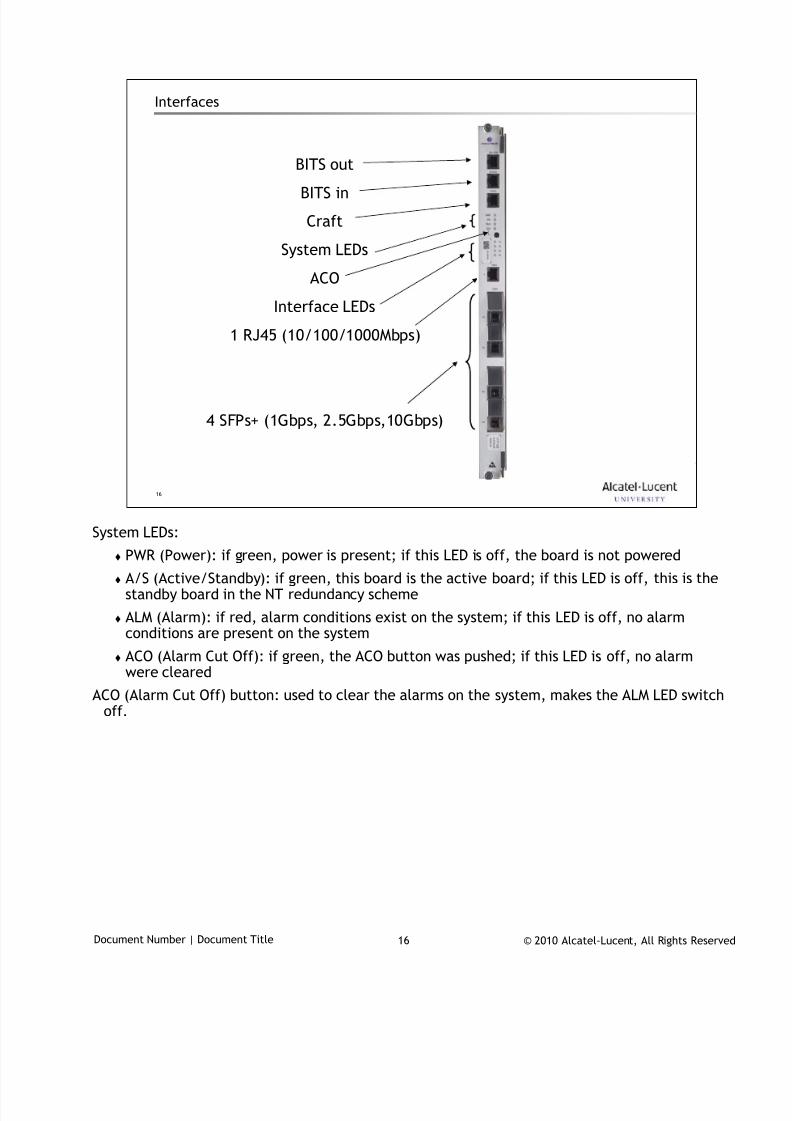
7/18/2019 Alu - A7302 Isam Fttu Operator Gpon Nant-e_ce-PDF
http://slidepdf.com/reader/full/alu-a7302-isam-fttu-operator-gpon-nant-ece-pdf 68/432
© 2010 Alcatel-Lucent, All Rights ReservedDocument Number | Document Title 16
16
Interfaces
BITS out
BITS in
Craft
System LEDs
ACO
Interface LEDs
1 RJ45 (10/100/1000Mbps)
4 SFPs+ (1Gbps, 2.5Gbps,10Gbps)
System LEDs:
PWR (Power): if green, power is present; if this LED is off, the board is not powered
A/S (Active/Standby): if green, this board is the active board; if this LED is off, this is thestandby board in the NT redundancy scheme
ALM (Alarm): if red, alarm conditions exist on the system; if this LED is off, no alarmconditions are present on the system
ACO (Alarm Cut Off): if green, the ACO button was pushed; if this LED is off, no alarmwere cleared
ACO (Alarm Cut Off) button: used to clear the alarms on the system, makes the ALM LED switchoff.
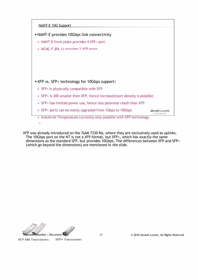
7/18/2019 Alu - A7302 Isam Fttu Operator Gpon Nant-e_ce-PDF
http://slidepdf.com/reader/full/alu-a7302-isam-fttu-operator-gpon-nant-ece-pdf 69/432
© 2010 Alcatel-Lucent, All Rights ReservedDocument Number | Document Title 17
17
NANT-E 10G Support
NANT-E provides 10Gbps link connectivity
• NANT-E front plate provides 4 SFP+ port
• NCNC-F (R4.1) provides 2 XFP ports
XFP vs. SFP+ technology for 10Gbps support:
• SFP+ is physically compatible with SFP
• SFP+ is 30% smaller then XFP, hence increased port density is possible
• SFP+ has limited power use, hence less potential reach than XFP
• SFP+ ports can be easily upgraded from 1Gbps to 10Gbps
• Industrial Temperature currently only possible with XFP technology
XFP was already introduced on the ISAM 7330 RA, where they are exclusively used as uplinks.
The 10Gbps port on the NT is not a XFP format, but SFP+, which has exactly the samedimensions as the standard SFP, but provides 10Gbps. The differences between XFP and SFP+(which go beyond the dimensions) are mentioned in the slide.
7/18/2019 Alu - A7302 Isam Fttu Operator Gpon Nant-e_ce-PDF
http://slidepdf.com/reader/full/alu-a7302-isam-fttu-operator-gpon-nant-ece-pdf 70/432
© 2010 Alcatel-Lucent, All Rights ReservedDocument Number | Document Title 18
18
Access Network Topologies3
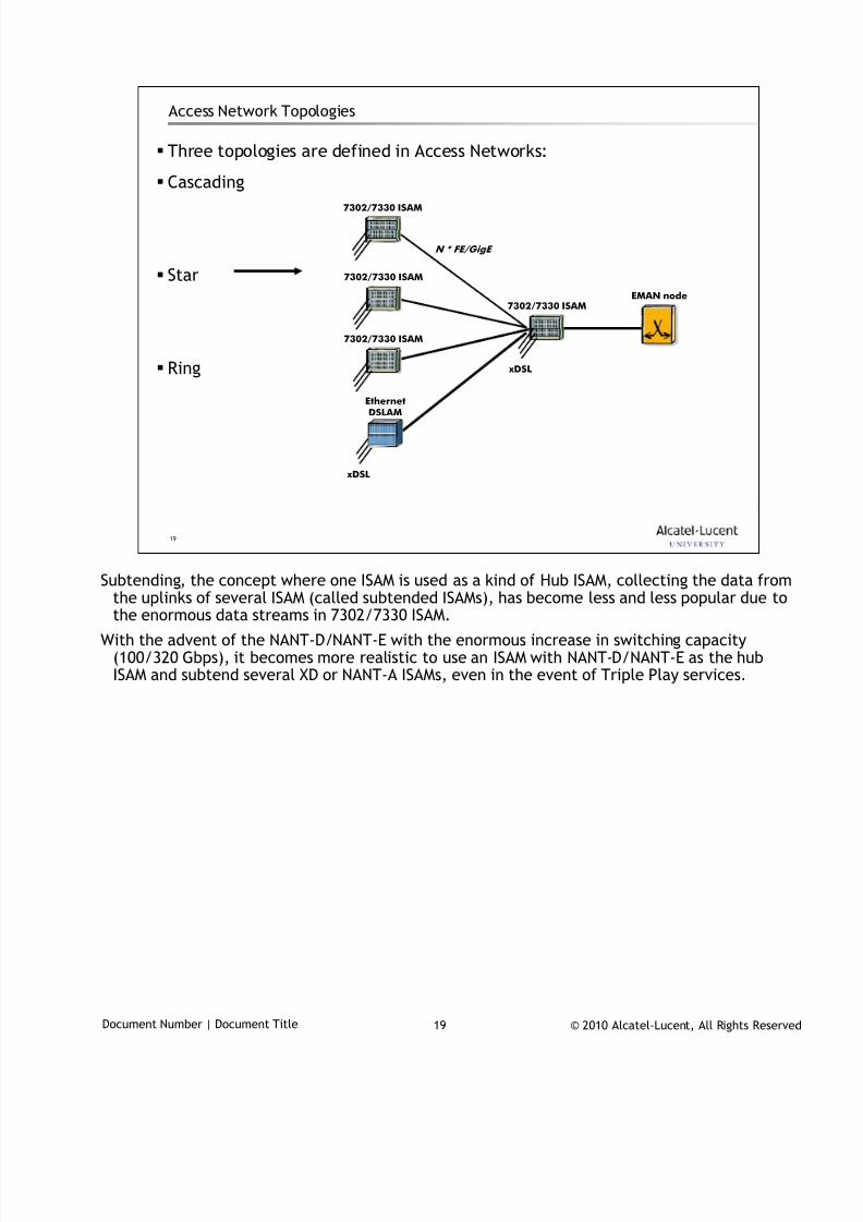
7/18/2019 Alu - A7302 Isam Fttu Operator Gpon Nant-e_ce-PDF
http://slidepdf.com/reader/full/alu-a7302-isam-fttu-operator-gpon-nant-ece-pdf 71/432
© 2010 Alcatel-Lucent, All Rights ReservedDocument Number | Document Title 19
19
Access Network Topologies
Three topologies are defined in Access Networks:
Cascading
Star
Ring
7302/7330 ISAM
xDSL
7302/7330 ISAM
7302/7330 ISAM
7302/7330 ISAM
xDSL
Ethernet
DSLAM
EMAN node
N * FE/GigE
Subtending, the concept where one ISAM is used as a kind of Hub ISAM, collecting the data from
the uplinks of several ISAM (called subtended ISAMs), has become less and less popular due tothe enormous data streams in 7302/7330 ISAM.
With the advent of the NANT-D/NANT-E with the enormous increase in switching capacity(100/320 Gbps), it becomes more realistic to use an ISAM with NANT-D/NANT-E as the hubISAM and subtend several XD or NANT-A ISAMs, even in the event of Triple Play services.
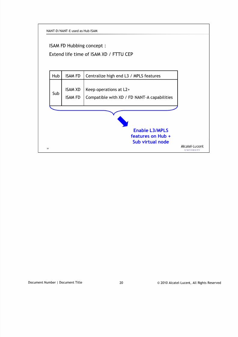
7/18/2019 Alu - A7302 Isam Fttu Operator Gpon Nant-e_ce-PDF
http://slidepdf.com/reader/full/alu-a7302-isam-fttu-operator-gpon-nant-ece-pdf 72/432
© 2010 Alcatel-Lucent, All Rights ReservedDocument Number | Document Title 20
20
NANT-D/NANT-E used as Hub ISAM
ISAM FD Hubbing concept :
Extend life time of ISAM XD / FTTU CEP
Keep operations at L2+
Compatible with XD / FD NANT-A capabilities
ISAM XD
ISAM FDSub
Centralize high end L3 / MPLS featuresISAM FDHub
Enable L3/MPLSfeatures on Hub +Sub virtual node
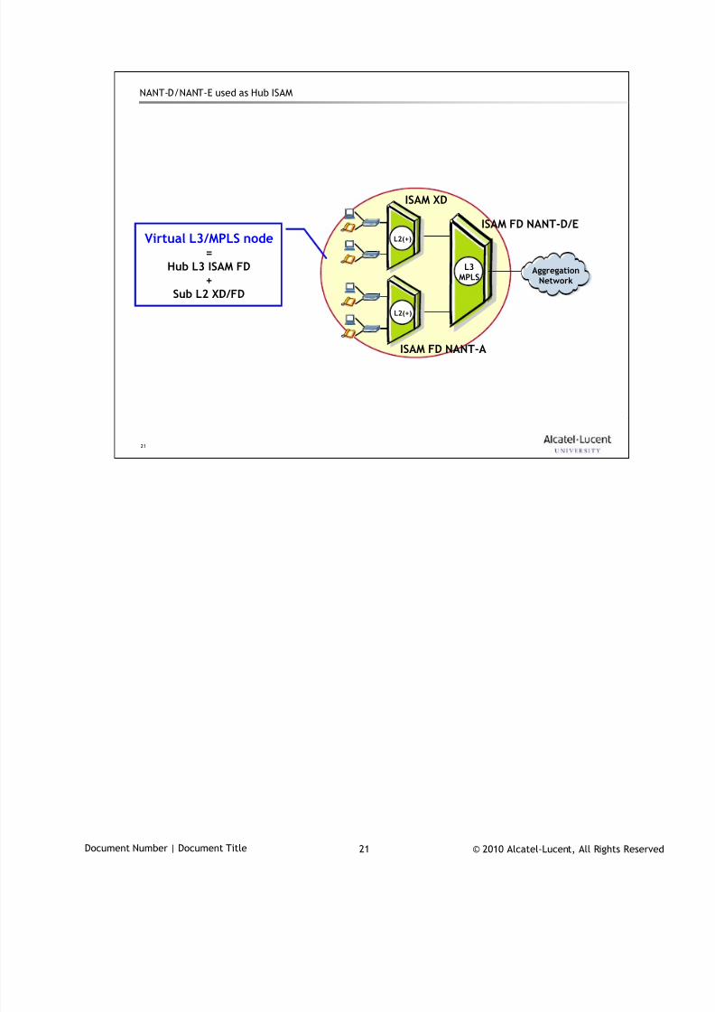
7/18/2019 Alu - A7302 Isam Fttu Operator Gpon Nant-e_ce-PDF
http://slidepdf.com/reader/full/alu-a7302-isam-fttu-operator-gpon-nant-ece-pdf 73/432
© 2010 Alcatel-Lucent, All Rights ReservedDocument Number | Document Title 21
21
NANT-D/NANT-E used as Hub ISAM
AggregationNetwork
L2(+)
L3MPLS
L2(+)
ISAM FD NANT-D/E
ISAM XD
ISAM FD NANT-A
Virtual L3/MPLS node=
Hub L3 ISAM FD+
Sub L2 XD/FD

7/18/2019 Alu - A7302 Isam Fttu Operator Gpon Nant-e_ce-PDF
http://slidepdf.com/reader/full/alu-a7302-isam-fttu-operator-gpon-nant-ece-pdf 74/432
© 2010 Alcatel-Lucent, All Rights ReservedDocument Number | Document Title 22
22
www.alcatel-lucent.comwww.alcatel-lucent.com

7/18/2019 Alu - A7302 Isam Fttu Operator Gpon Nant-e_ce-PDF
http://slidepdf.com/reader/full/alu-a7302-isam-fttu-operator-gpon-nant-ece-pdf 75/432
© 2010 Alcatel-Lucent, All Rights ReservedDocument Number | Document Title 1
ONT portfolio
During class please switch off your mobile, pager or other that may interrupt.

7/18/2019 Alu - A7302 Isam Fttu Operator Gpon Nant-e_ce-PDF
http://slidepdf.com/reader/full/alu-a7302-isam-fttu-operator-gpon-nant-ece-pdf 76/432
© 2010 Alcatel-Lucent, All Rights ReservedDocument Number | Document Title 2
2
Objective
Upon completion of the module you will be able to
list the functions and properties of a generic ONT
describe the nomenclature used for the different ONT families
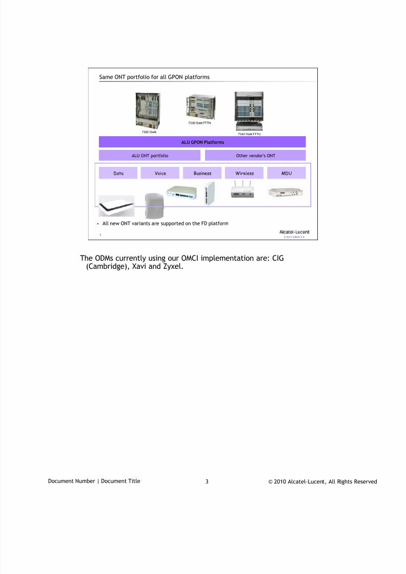
7/18/2019 Alu - A7302 Isam Fttu Operator Gpon Nant-e_ce-PDF
http://slidepdf.com/reader/full/alu-a7302-isam-fttu-operator-gpon-nant-ece-pdf 77/432
© 2010 Alcatel-Lucent, All Rights ReservedDocument Number | Document Title 3
3
Same ONT portfolio for all GPON platforms
7302 ISAM
7330 ISAM FTTN
7342 ISAM FTTU
Data Voice Business Wireless MDU
ALU ONT portfolio Other vendor’s ONT
ALU GPON Platforms
• All new ONT variants are supported on the FD platform
The ODMs currently using our OMCI implementation are: CIG(Cambridge), Xavi and Zyxel.
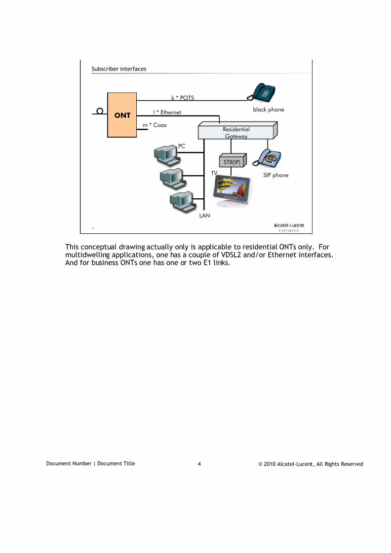
7/18/2019 Alu - A7302 Isam Fttu Operator Gpon Nant-e_ce-PDF
http://slidepdf.com/reader/full/alu-a7302-isam-fttu-operator-gpon-nant-ece-pdf 78/432
© 2010 Alcatel-Lucent, All Rights ReservedDocument Number | Document Title 4
4
Subscriber interfaces
ONT
ResidentialGateway
STB(IP)
l * Ethernet
k * POTS
LAN
TV
PC
m * Coax
SIP phone
black phone
This conceptual drawing actually only is applicable to residential ONTs only. Formultidwelling applications, one has a couple of VDSL2 and/or Ethernet interfaces.And for business ONTs one has one or two E1 links.
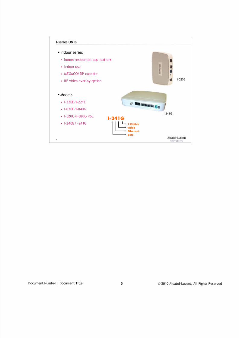
7/18/2019 Alu - A7302 Isam Fttu Operator Gpon Nant-e_ce-PDF
http://slidepdf.com/reader/full/alu-a7302-isam-fttu-operator-gpon-nant-ece-pdf 79/432
© 2010 Alcatel-Lucent, All Rights ReservedDocument Number | Document Title 5
5
I-series ONTs
Indoor series
• home/residential applications
• indoor use
• MEGACO/SIP capable
• RF video overlay option
Models
• I-220E/I-221E
• I-020E/I-040G
• I-020G/I-020G PoE
• I-240G/I-241G
I-020E
I-241G
I-241G1 Gbit/s
video
Ethernet
pots

7/18/2019 Alu - A7302 Isam Fttu Operator Gpon Nant-e_ce-PDF
http://slidepdf.com/reader/full/alu-a7302-isam-fttu-operator-gpon-nant-ece-pdf 80/432
© 2010 Alcatel-Lucent, All Rights ReservedDocument Number | Document Title 6
6
O-series ONTs
Outdoor series
• home/residential applications
• outdoor use
• temperature hardened
• MEGACO/SIP capable
• locally powered with battery backup
• 12V power feed with UPS
• RF video overlay option
Models
• O-210E/O-211E
• O-420E/O-421E
O-421E100 Mbit/s
video
Ethernet
pots

7/18/2019 Alu - A7302 Isam Fttu Operator Gpon Nant-e_ce-PDF
http://slidepdf.com/reader/full/alu-a7302-isam-fttu-operator-gpon-nant-ece-pdf 81/432
© 2010 Alcatel-Lucent, All Rights ReservedDocument Number | Document Title 7
7
B-series ONTs
Business series
• business/SOHO applications
• outdoor use
• temperature hardened
• MEGACO/SIP capable
• RF video overlay option
• E1 support
Models• B-8102G
• B-8112G
• B-0404G
B-8112G 1 Gbit/s
video
Ethernet
pots
E1
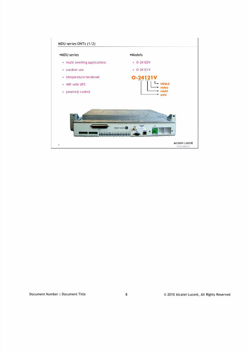
7/18/2019 Alu - A7302 Isam Fttu Operator Gpon Nant-e_ce-PDF
http://slidepdf.com/reader/full/alu-a7302-isam-fttu-operator-gpon-nant-ece-pdf 82/432
© 2010 Alcatel-Lucent, All Rights ReservedDocument Number | Document Title 8
8
MDU-series ONTs (1/2)
MDU series
• multi dwelling applications
• outdoor use
• temperature hardened
• 48V with UPS
• passively cooled
Models
• O-24120V
• O-24121V
O-24121V VDSL2
vdsl2
pots
video
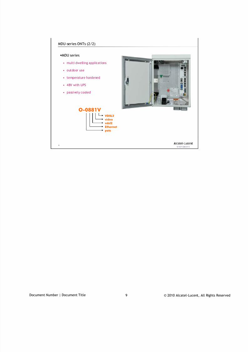
7/18/2019 Alu - A7302 Isam Fttu Operator Gpon Nant-e_ce-PDF
http://slidepdf.com/reader/full/alu-a7302-isam-fttu-operator-gpon-nant-ece-pdf 83/432
© 2010 Alcatel-Lucent, All Rights ReservedDocument Number | Document Title 9
9
MDU-series ONTs (2/2)
O-0881V
MDU series• multi dwelling applications
• outdoor use
• temperature hardened
• 48V with UPS
• passively cooled
VDSL2
vdsl2
Ethernet
pots
video
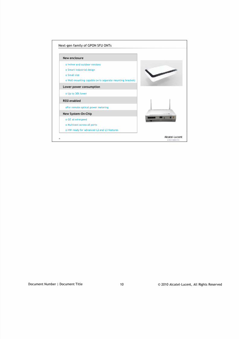
7/18/2019 Alu - A7302 Isam Fttu Operator Gpon Nant-e_ce-PDF
http://slidepdf.com/reader/full/alu-a7302-isam-fttu-operator-gpon-nant-ece-pdf 84/432
© 2010 Alcatel-Lucent, All Rights ReservedDocument Number | Document Title 10
10
Next-gen family of GPON SFU ONTs
o GE at wirespeed
o Multicast across all ports
o HW ready for advanced L2 and L3 features
oFor remote optical power metering
o Up to 30% lower
o Indoor and outdoor versions
o Smart industrial design
o Small size
o Wall-mounting capable (w/o separate mounting bracket)
New System-On-Chip
RSSI enabled
Lower power consumption
New enclosure
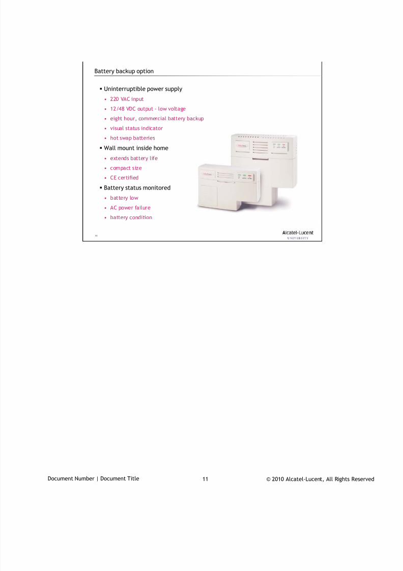
7/18/2019 Alu - A7302 Isam Fttu Operator Gpon Nant-e_ce-PDF
http://slidepdf.com/reader/full/alu-a7302-isam-fttu-operator-gpon-nant-ece-pdf 85/432
© 2010 Alcatel-Lucent, All Rights ReservedDocument Number | Document Title 11
11
Battery backup option
Uninterruptible power supply
• 220 VAC input
• 12/48 VDC output - low voltage
• eight hour, commercial battery backup
• visual status indicator
• hot swap batteries
Wall mount inside home
• extends battery life
• compact size
• CE certified
Battery status monitored
• battery low
• AC power failure
• battery condition

7/18/2019 Alu - A7302 Isam Fttu Operator Gpon Nant-e_ce-PDF
http://slidepdf.com/reader/full/alu-a7302-isam-fttu-operator-gpon-nant-ece-pdf 86/432
© 2010 Alcatel-Lucent, All Rights ReservedDocument Number | Document Title 12
12
www.alcatel-lucent.comwww.alcatel-lucent.com
7/18/2019 Alu - A7302 Isam Fttu Operator Gpon Nant-e_ce-PDF
http://slidepdf.com/reader/full/alu-a7302-isam-fttu-operator-gpon-nant-ece-pdf 87/432
© 2010 Alcatel-Lucent, All Rights ReservedTAC03001 – HO07 1
CLI Introduction
During class please switch off your mobile, pager or other that may interrupt.

7/18/2019 Alu - A7302 Isam Fttu Operator Gpon Nant-e_ce-PDF
http://slidepdf.com/reader/full/alu-a7302-isam-fttu-operator-gpon-nant-ece-pdf 88/432
© 2010 Alcatel-Lucent, All Rights ReservedTAC03001 – HO07 2
Objective
At the end of the module you will be able to
connect ISAM with CLI and manage configuration, database
information as an entry level operator
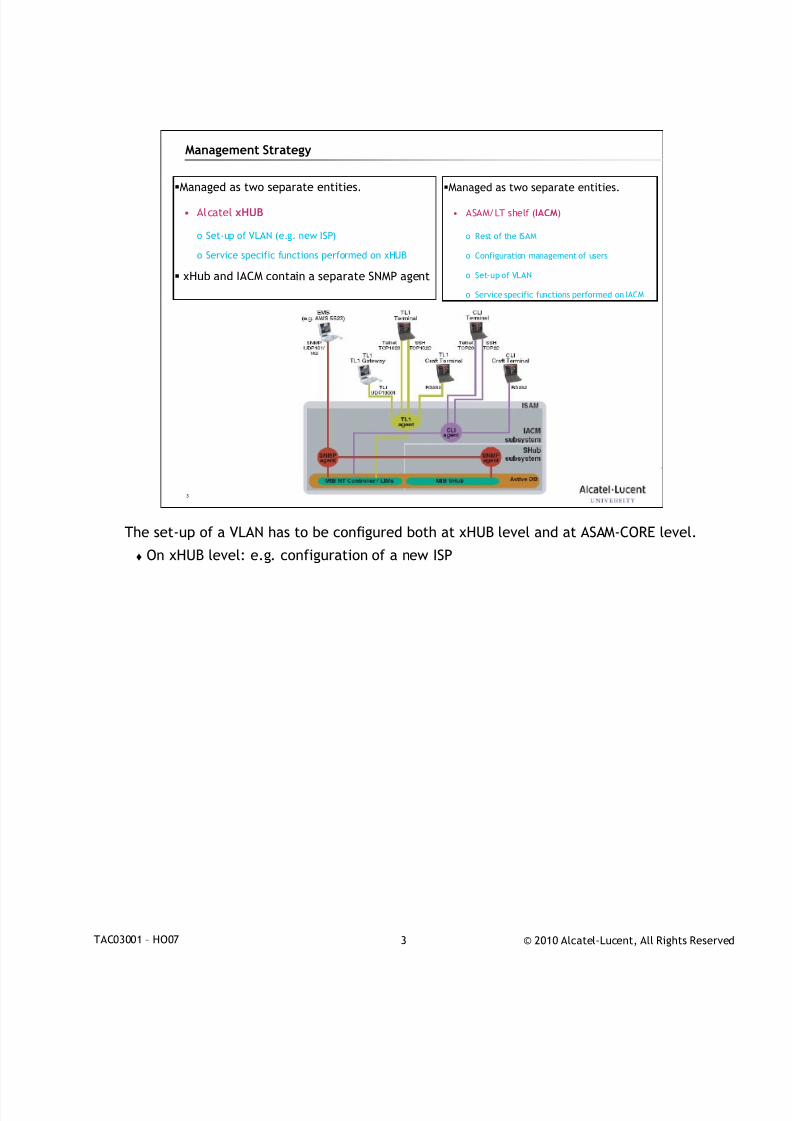
7/18/2019 Alu - A7302 Isam Fttu Operator Gpon Nant-e_ce-PDF
http://slidepdf.com/reader/full/alu-a7302-isam-fttu-operator-gpon-nant-ece-pdf 89/432
© 2010 Alcatel-Lucent, All Rights ReservedTAC03001 – HO07 3
3
Management Strategy
Managed as two separate entities.
• Alcatel xHUB
o Set-up of VLAN (e.g. new ISP)
o Service specific functions performed on xHUB
xHub and IACM contain a separate SNMP agent
Managed as two separate entities.
• ASAM/LT shelf (IACM)
o Rest of the ISAM
o Configuration management of users
o Set-up of VLAN
o Service specific functions performed on IACM
The set-up of a VLAN has to be configured both at xHUB level and at ASAM-CORE level.
On xHUB level: e.g. configuration of a new ISP
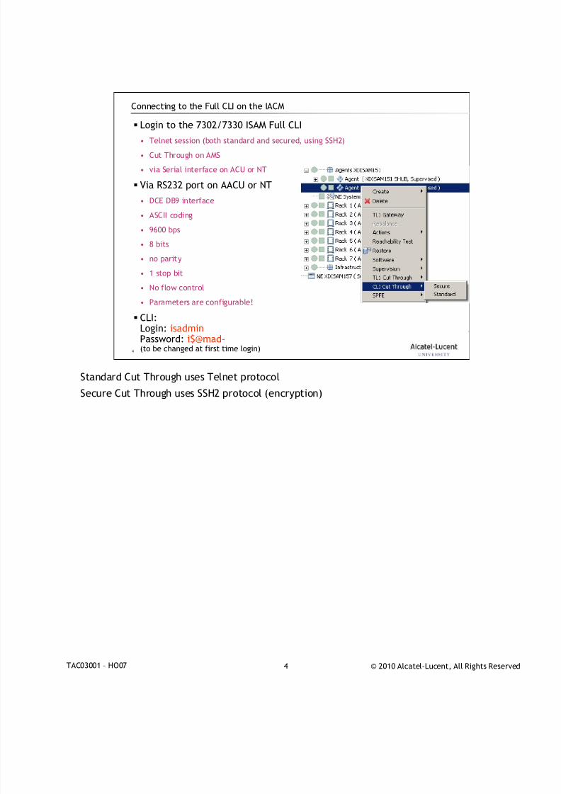
7/18/2019 Alu - A7302 Isam Fttu Operator Gpon Nant-e_ce-PDF
http://slidepdf.com/reader/full/alu-a7302-isam-fttu-operator-gpon-nant-ece-pdf 90/432
© 2010 Alcatel-Lucent, All Rights ReservedTAC03001 – HO07 4
4
Connecting to the Full CLI on the IACM
Login to the 7302/7330 ISAM Full CLI• Telnet session (both standard and secured, using SSH2)
• Cut Through on AMS
• via Serial interface on ACU or NT
Via RS232 port on AACU or NT
• DCE DB9 interface
• ASCII coding
• 9600 bps
• 8 bits
• no parity
• 1 stop bit
• No flow control
• Parameters are configurable!
CLI:Login: isadminPassword: i$@mad-(to be changed at first time login)
Standard Cut Through uses Telnet protocol
Secure Cut Through uses SSH2 protocol (encryption)
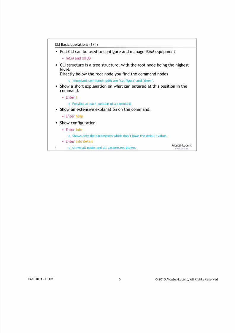
7/18/2019 Alu - A7302 Isam Fttu Operator Gpon Nant-e_ce-PDF
http://slidepdf.com/reader/full/alu-a7302-isam-fttu-operator-gpon-nant-ece-pdf 91/432
© 2010 Alcatel-Lucent, All Rights ReservedTAC03001 – HO07 5
5
CLI Basic operations (1/4)
Full CLI can be used to configure and manage ISAM equipment
• IACM and xHUB
CLI structure is a tree structure, with the root node being the highestlevel.Directly below the root node you find the command nodes
o Important command nodes are ‘configure’ and ‘show’.
Show a short explanation on what can entered at this position in thecommand..
• Enter ?
o Possible at each position of a command
Show an extensive explanation on the command.
• Enter help
Show configuration
• Enter info
o Shows only the parameters which don’t have the default value.
• Enter info detail
o shows all nodes and all parameters shown.

7/18/2019 Alu - A7302 Isam Fttu Operator Gpon Nant-e_ce-PDF
http://slidepdf.com/reader/full/alu-a7302-isam-fttu-operator-gpon-nant-ece-pdf 92/432
© 2010 Alcatel-Lucent, All Rights ReservedTAC03001 – HO07 6
6
CLI Basic operations (2/4)
Move cursor left one space• press <left arrow>
Move cursor right one space
• press <right arrow>
Recall previous command
• press <up arrow> or <ctrl>p
Recall successive commands
• press <down arrow> or <ctrl>n
Delete previous input character
• press <backspace>
Delete character under the cursor
• press <delete>.
Toggle between insert and overwrite mode.
• press <insert>.

7/18/2019 Alu - A7302 Isam Fttu Operator Gpon Nant-e_ce-PDF
http://slidepdf.com/reader/full/alu-a7302-isam-fttu-operator-gpon-nant-ece-pdf 93/432
© 2010 Alcatel-Lucent, All Rights ReservedTAC03001 – HO07 7
7
CLI Basic operations (3/4)
Reset command input processing
• press <ctrl>c.
Auto completion of the command when only entered partially
• Press <Space> or <Tab>
Go one level up
• Enter exit
Go to root prompt
• exit all
Go to the previous level you were at before you entered the last command
• Enter back
Display the last commands entered at the terminal.
• Enter history

7/18/2019 Alu - A7302 Isam Fttu Operator Gpon Nant-e_ce-PDF
http://slidepdf.com/reader/full/alu-a7302-isam-fttu-operator-gpon-nant-ece-pdf 94/432
© 2010 Alcatel-Lucent, All Rights ReservedTAC03001 – HO07 8
8
CLI Basic operations (4/4)
Display the structure of configurable nodes and subnodes.
• Enter tree
Filter
• < | match <parameters>
• Possible parameters displayed by entering <?>

7/18/2019 Alu - A7302 Isam Fttu Operator Gpon Nant-e_ce-PDF
http://slidepdf.com/reader/full/alu-a7302-isam-fttu-operator-gpon-nant-ece-pdf 95/432
© 2010 Alcatel-Lucent, All Rights ReservedTAC03001 – HO07 9
9
www.alcatel-lucent.comwww.alcatel-lucent.com

7/18/2019 Alu - A7302 Isam Fttu Operator Gpon Nant-e_ce-PDF
http://slidepdf.com/reader/full/alu-a7302-isam-fttu-operator-gpon-nant-ece-pdf 96/432
© 2010 Alcatel-Lucent, All Rights ReservedDocument Number | Document Title 1
Turn Up Procedure
During class please switch off your mobile, pager or other that may interrupt.

7/18/2019 Alu - A7302 Isam Fttu Operator Gpon Nant-e_ce-PDF
http://slidepdf.com/reader/full/alu-a7302-isam-fttu-operator-gpon-nant-ece-pdf 97/432
© 2010 Alcatel-Lucent, All Rights ReservedDocument Number | Document Title 2
Objective
After this section, you’ll be able to:
• Configure and turn-up a new ISAM
• Configure the ISAM’s IP-address
• Configure the network port, management VLAN and interface
• Set-up the SNMP management between 5520AMS and ISAM
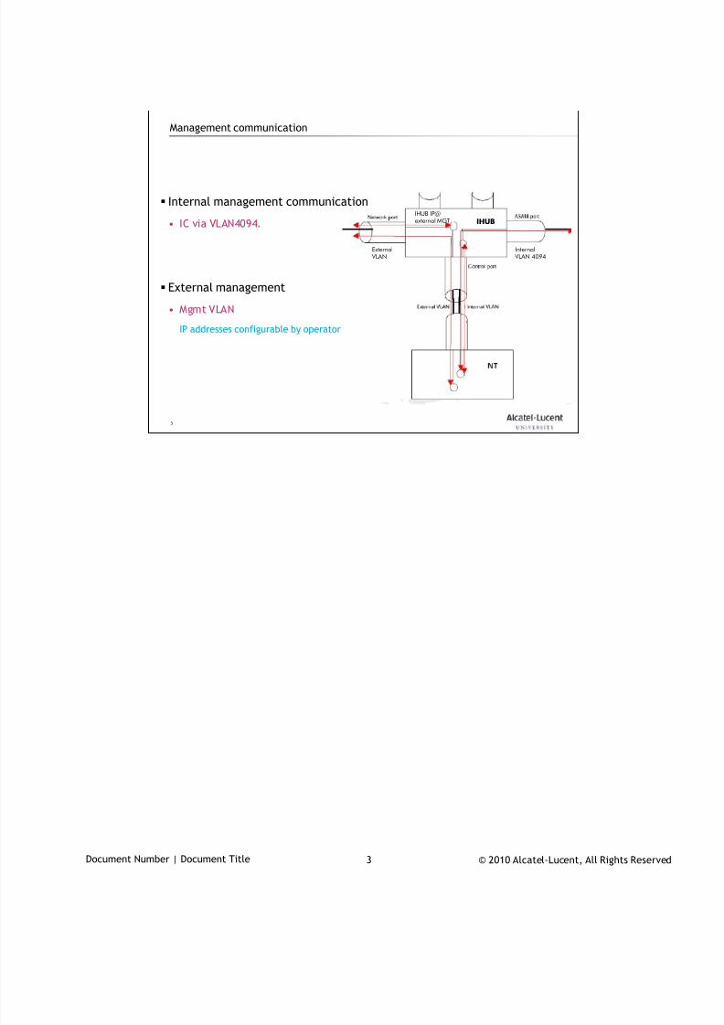
7/18/2019 Alu - A7302 Isam Fttu Operator Gpon Nant-e_ce-PDF
http://slidepdf.com/reader/full/alu-a7302-isam-fttu-operator-gpon-nant-ece-pdf 98/432
© 2010 Alcatel-Lucent, All Rights ReservedDocument Number | Document Title 3
3
Management communication
IHUB IP@
external MGT IHUB
Internal
VLAN 4094
External
VLAN
Internal management communication
• IC via VLAN4094.
External management
• Mgmt VLAN
IP addresses configurable by operator
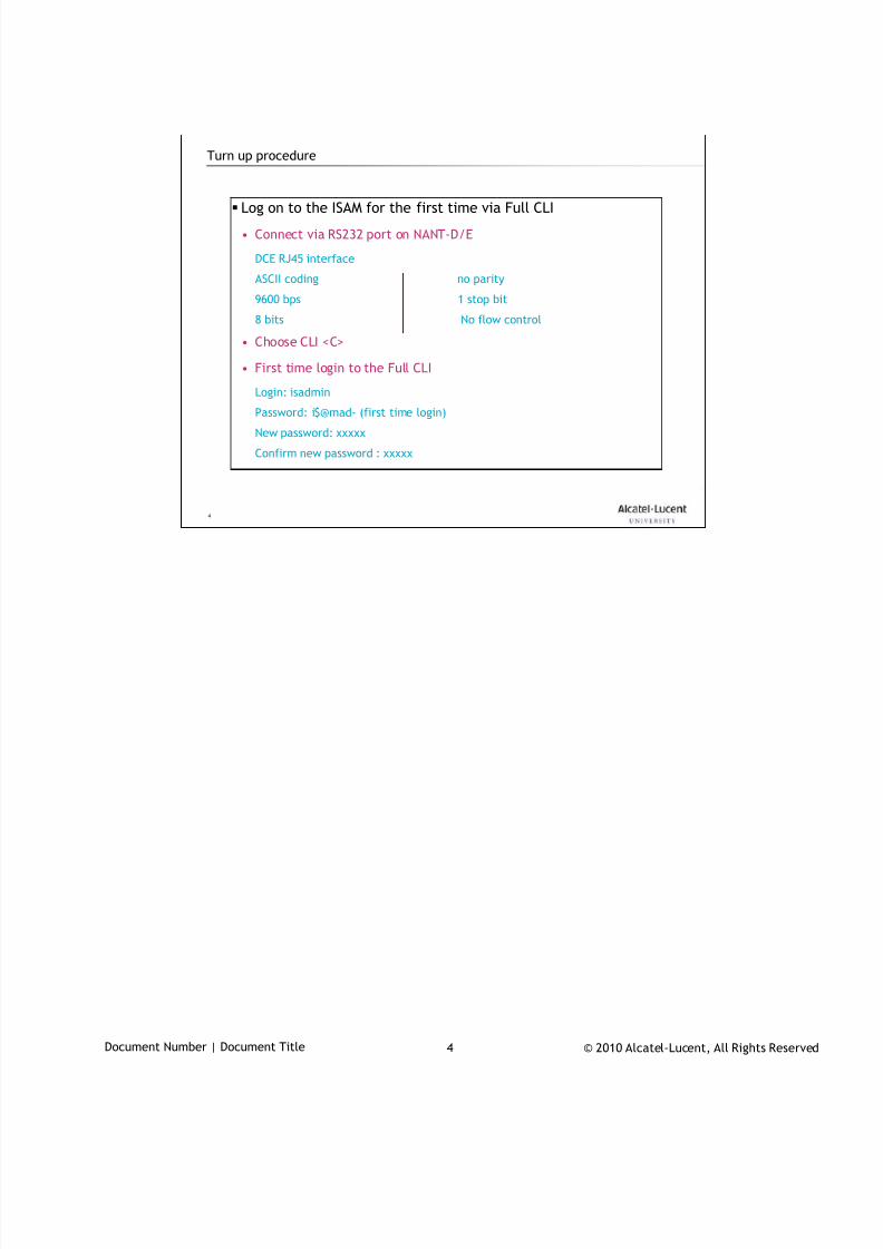
7/18/2019 Alu - A7302 Isam Fttu Operator Gpon Nant-e_ce-PDF
http://slidepdf.com/reader/full/alu-a7302-isam-fttu-operator-gpon-nant-ece-pdf 99/432
© 2010 Alcatel-Lucent, All Rights ReservedDocument Number | Document Title 4
4
Turn up procedure
Log on to the ISAM for the first time via Full CLI
• Connect via RS232 port on NANT-D/E
DCE RJ45 interface
ASCII coding no parity
9600 bps 1 stop bit
8 bits No flow control
• Choose CLI <C>
• First time login to the Full CLI
Login: isadmin
Password: i$@mad- (first time login)
New password: xxxxx
Confirm new password : xxxxx
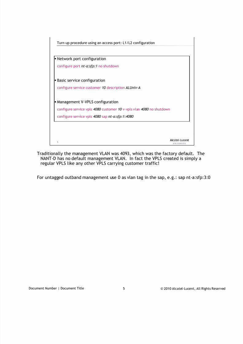
7/18/2019 Alu - A7302 Isam Fttu Operator Gpon Nant-e_ce-PDF
http://slidepdf.com/reader/full/alu-a7302-isam-fttu-operator-gpon-nant-ece-pdf 100/432
© 2010 Alcatel-Lucent, All Rights ReservedDocument Number | Document Title 5
5
Turn up procedure using an access port: L1/L2 configuration
Network port configuration
configure port nt-a:sfp:1 no shutdown
Basic service configuration
configure service customer 10 description ALUniv-A
Management V-VPLS configuration
configure service vpls 4080 customer 10 v-vpls vlan 4080 no shutdown
configure service vpls 4080 sap nt-a:sfp:1:4080
Traditionally the management VLAN was 4093, which was the factory default. TheNANT-D has no default management VLAN. In fact the VPLS created is simply aregular VPLS like any other VPLS carrying customer traffic!
For untagged outband management use 0 as vlan tag in the sap, e.g.: sap nt-a:sfp:3:0
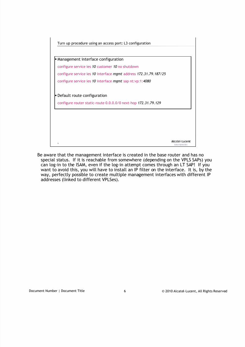
7/18/2019 Alu - A7302 Isam Fttu Operator Gpon Nant-e_ce-PDF
http://slidepdf.com/reader/full/alu-a7302-isam-fttu-operator-gpon-nant-ece-pdf 101/432
© 2010 Alcatel-Lucent, All Rights ReservedDocument Number | Document Title 6
6
Turn up procedure using an access port: L3 configuration
Management interface configuration
configure service ies 10 customer 10 no shutdown
configure service ies 10 interface mgmt address 172.31.79.187/25
configure service ies 10 interface mgmt sap nt:vp:1:4080
Default route configuration
configure router static-route 0.0.0.0/0 next-hop 172.31.79.129
Be aware that the management interface is created in the base router and has nospecial status. If it is reachable from somewhere (depending on the VPLS SAPs) youcan log-in to the ISAM, even if the log-in attempt comes through an LT SAP! If you
want to avoid this, you will have to install an IP filter on the interface. It is, by theway, perfectly possible to create multiple management interfaces with different IPaddresses (linked to different VPLSes).
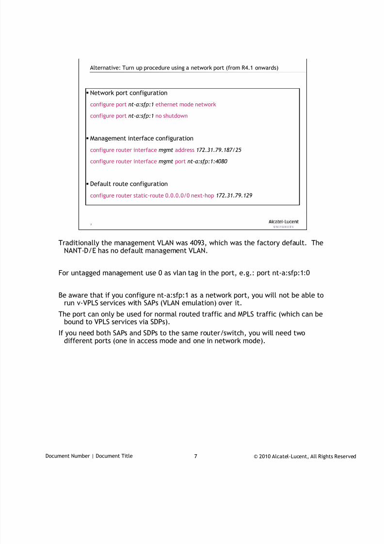
7/18/2019 Alu - A7302 Isam Fttu Operator Gpon Nant-e_ce-PDF
http://slidepdf.com/reader/full/alu-a7302-isam-fttu-operator-gpon-nant-ece-pdf 102/432
© 2010 Alcatel-Lucent, All Rights ReservedDocument Number | Document Title 7
7
Alternative: Turn up procedure using a network port (from R4.1 onwards)
Network port configuration
configure port nt-a:sfp:1 ethernet mode network
configure port nt-a:sfp:1 no shutdown
Management interface configuration
configure router interface mgmt address 172.31.79.187/25
configure router interface mgmt port nt-a:sfp:1:4080
Default route configuration
configure router static-route 0.0.0.0/0 next-hop 172.31.79.129
Traditionally the management VLAN was 4093, which was the factory default. TheNANT-D/E has no default management VLAN.
For untagged management use 0 as vlan tag in the port, e.g.: port nt-a:sfp:1:0
Be aware that if you configure nt-a:sfp:1 as a network port, you will not be able torun v-VPLS services with SAPs (VLAN emulation) over it.
The port can only be used for normal routed traffic and MPLS traffic (which can bebound to VPLS services via SDPs).
If you need both SAPs and SDPs to the same router/switch, you will need twodifferent ports (one in access mode and one in network mode).
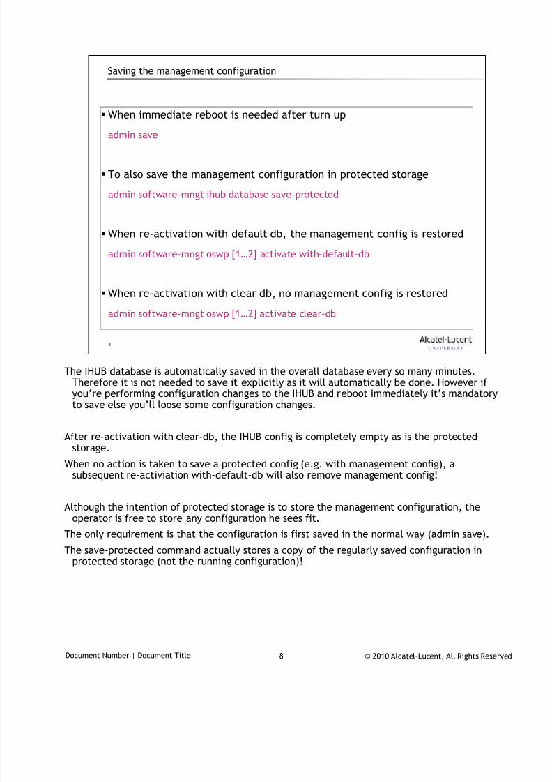
7/18/2019 Alu - A7302 Isam Fttu Operator Gpon Nant-e_ce-PDF
http://slidepdf.com/reader/full/alu-a7302-isam-fttu-operator-gpon-nant-ece-pdf 103/432
© 2010 Alcatel-Lucent, All Rights ReservedDocument Number | Document Title 8
8
Saving the management configuration
When immediate reboot is needed after turn up
admin save
To also save the management configuration in protected storage
admin software-mngt ihub database save-protected
When re-activation with default db, the management config is restored
admin software-mngt oswp [1…2] activate with-default-db
When re-activation with clear db, no management config is restored
admin software-mngt oswp [1…2] activate clear-db
The IHUB database is automatically saved in the overall database every so many minutes.
Therefore it is not needed to save it explicitly as it will automatically be done. However ifyou’re performing configuration changes to the IHUB and reboot immediately it’s mandatoryto save else you’ll loose some configuration changes.
After re-activation with clear-db, the IHUB config is completely empty as is the protectedstorage.
When no action is taken to save a protected config (e.g. with management config), asubsequent re-activiation with-default-db will also remove management config!
Although the intention of protected storage is to store the management configuration, theoperator is free to store any configuration he sees fit.
The only requirement is that the configuration is first saved in the normal way (admin save).
The save-protected command actually stores a copy of the regularly saved configuration inprotected storage (not the running configuration)!

7/18/2019 Alu - A7302 Isam Fttu Operator Gpon Nant-e_ce-PDF
http://slidepdf.com/reader/full/alu-a7302-isam-fttu-operator-gpon-nant-ece-pdf 104/432
© 2010 Alcatel-Lucent, All Rights ReservedDocument Number | Document Title 9
9
The system interface (1)
The base router has a system interface
• It always exists by default and it is a loopback interface (no port)
• It is only reachable from outside through real interfaces (with ports)
• It has no address by default
Its address is used by the IHUB for self-generated traffic
• Routing protocols
• MPLS
• IGMP (by default)
• DHCP relaying
• …
It is however only used when an address is configured!
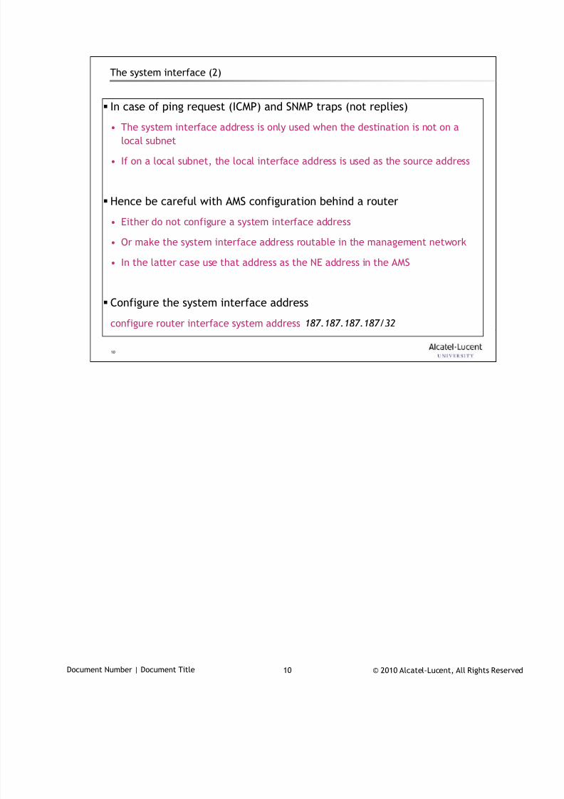
7/18/2019 Alu - A7302 Isam Fttu Operator Gpon Nant-e_ce-PDF
http://slidepdf.com/reader/full/alu-a7302-isam-fttu-operator-gpon-nant-ece-pdf 105/432
© 2010 Alcatel-Lucent, All Rights ReservedDocument Number | Document Title 10
10
The system interface (2)
In case of ping request (ICMP) and SNMP traps (not replies)
• The system interface address is only used when the destination is not on alocal subnet
• If on a local subnet, the local interface address is used as the source address
Hence be careful with AMS configuration behind a router
• Either do not configure a system interface address
• Or make the system interface address routable in the management network
• In the latter case use that address as the NE address in the AMS
Configure the system interface address
configure router interface system address 187.187.187.187/32
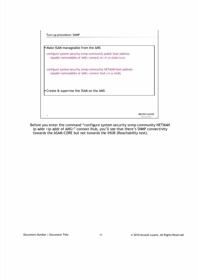
7/18/2019 Alu - A7302 Isam Fttu Operator Gpon Nant-e_ce-PDF
http://slidepdf.com/reader/full/alu-a7302-isam-fttu-operator-gpon-nant-ece-pdf 106/432
© 2010 Alcatel-Lucent, All Rights ReservedDocument Number | Document Title 11
11
Turn up procedure: SNMP
Make ISAM manageable from the AMS
configure system security snmp community public host-address
<ipaddr/netmaskbits of AMS> context nt ( on ASAM-Core)
configure system security snmp community NETMAN host-address
<ipaddr/netmaskbits of AMS> context ihub ( on IHUB)
Create & supervise the ISAM on the AMS
Before you enter the command “configure system security snmp community NETMANip-addr <ip-addr of AMS>” context ihub, you’ll see that there’s SNMP connectivitytowards the ASAM-CORE but not towards the IHUB (Reachability test).

7/18/2019 Alu - A7302 Isam Fttu Operator Gpon Nant-e_ce-PDF
http://slidepdf.com/reader/full/alu-a7302-isam-fttu-operator-gpon-nant-ece-pdf 107/432
© 2010 Alcatel-Lucent, All Rights ReservedDocument Number | Document Title 12
12
Manage NE in AMS 5520
Once turn-up procedure finished you need to manage the ISAM in the AMS(see chapter on AMS Introduction)
Afterwards, some basic decisions need to be taken at this point to avoidunnecessary reboots during operation:
• Whether you are going to use NT-B and NTIO slot as universal slot instead
• REM/SEM configuration if applicable
• SFP direction (up or down), if used for expansion
• QoS basic setting (port of VLAN based, QoS)

7/18/2019 Alu - A7302 Isam Fttu Operator Gpon Nant-e_ce-PDF
http://slidepdf.com/reader/full/alu-a7302-isam-fttu-operator-gpon-nant-ece-pdf 108/432
© 2010 Alcatel-Lucent, All Rights ReservedDocument Number | Document Title 13
13
www.alcatel-lucent.comwww.alcatel-lucent.com
7/18/2019 Alu - A7302 Isam Fttu Operator Gpon Nant-e_ce-PDF
http://slidepdf.com/reader/full/alu-a7302-isam-fttu-operator-gpon-nant-ece-pdf 109/432
© 2010 Alcatel-Lucent, All Rights ReservedTAC03001-HO08 1
Equipment Configuration
During class please switch off your mobile, pager or other that may interrupt.

7/18/2019 Alu - A7302 Isam Fttu Operator Gpon Nant-e_ce-PDF
http://slidepdf.com/reader/full/alu-a7302-isam-fttu-operator-gpon-nant-ece-pdf 110/432
© 2010 Alcatel-Lucent, All Rights ReservedTAC03001-HO08 2
Objective
At the end of the module you will be able to
prepare ISAM for the services in terms of equipment configuration
• LTs
• NT-B and NT-I/O cards
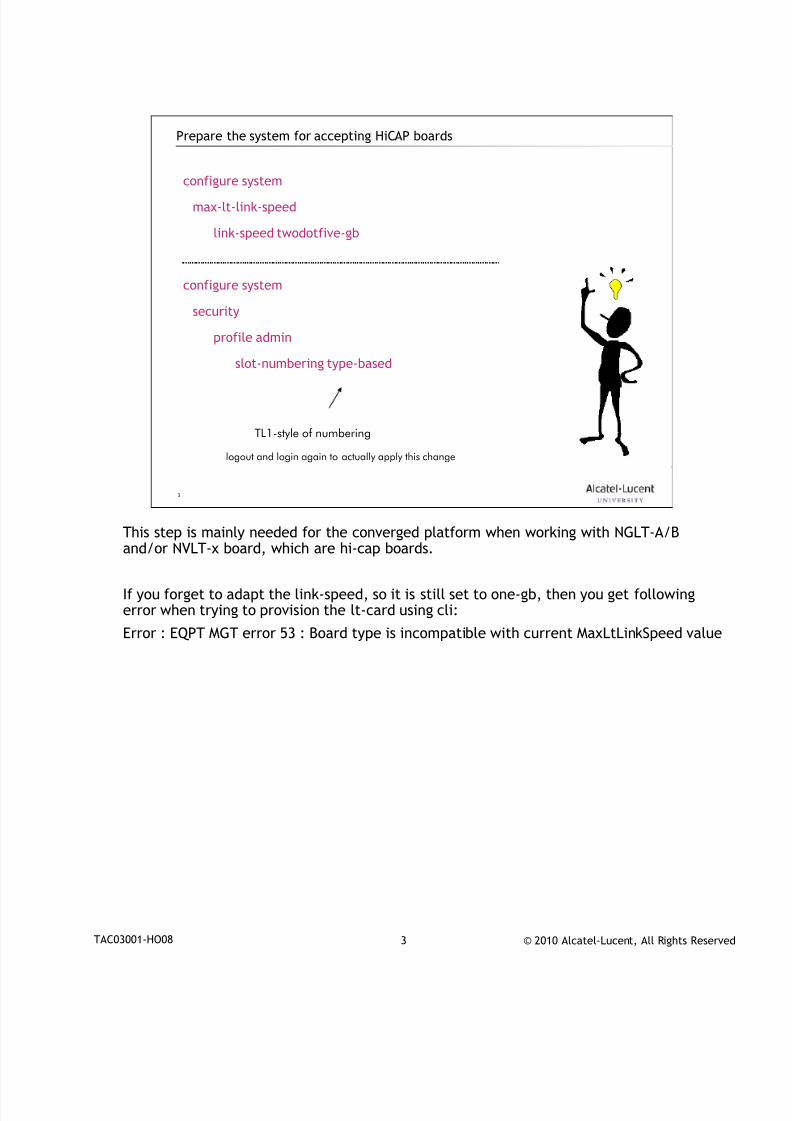
7/18/2019 Alu - A7302 Isam Fttu Operator Gpon Nant-e_ce-PDF
http://slidepdf.com/reader/full/alu-a7302-isam-fttu-operator-gpon-nant-ece-pdf 111/432
© 2010 Alcatel-Lucent, All Rights ReservedTAC03001-HO08 3
3
Prepare the system for accepting HiCAP boards
configure system
max-lt-link-speed
link-speed twodotfive-gb
configure system
security
profile admin
slot-numbering type-based
TL1-style of numbering
logout and login again to actually apply this change
This step is mainly needed for the converged platform when working with NGLT-A/B
and/or NVLT-x board, which are hi-cap boards.
If you forget to adapt the link-speed, so it is still set to one-gb, then you get followingerror when trying to provision the lt-card using cli:
Error : EQPT MGT error 53 : Board type is incompatible with current MaxLtLinkSpeed value
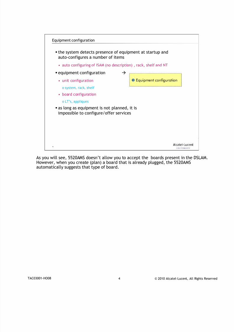
7/18/2019 Alu - A7302 Isam Fttu Operator Gpon Nant-e_ce-PDF
http://slidepdf.com/reader/full/alu-a7302-isam-fttu-operator-gpon-nant-ece-pdf 112/432
© 2010 Alcatel-Lucent, All Rights ReservedTAC03001-HO08 4
4
Equipment configuration
the system detects presence of equipment at startup andauto-configures a number of items
• auto configuring of ISAM (no description) , rack, shelf and NT
equipment configuration
• unit configuration
o system, rack, shelf
• board configuration
o LT’s, appliques
as long as equipment is not planned, it isimpossible to configure/offer services
Equipment configuration
As you will see, 5520AMS doesn’t allow you to accept the boards present in the DSLAM.
However, when you create (plan) a board that is already plugged, the 5520AMSautomatically suggests that type of board.
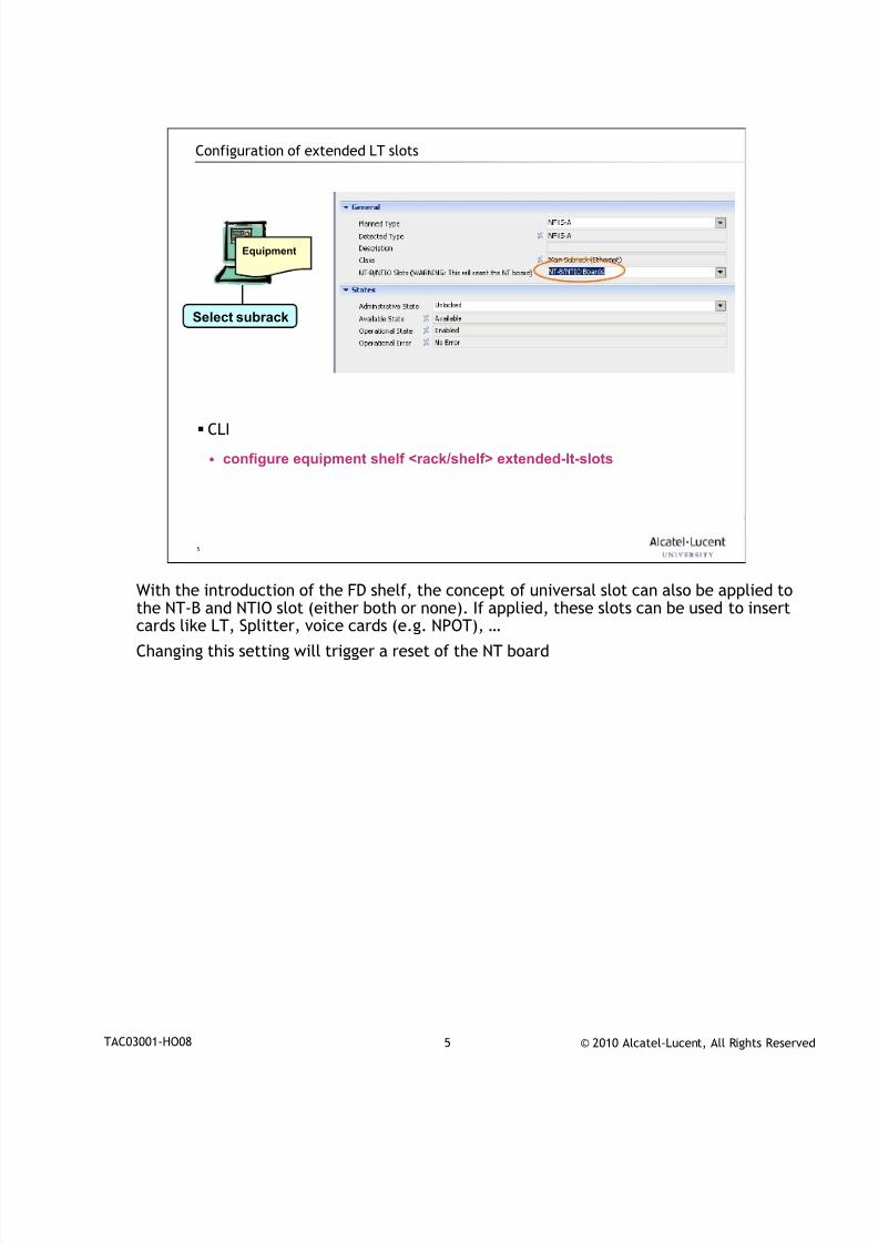
7/18/2019 Alu - A7302 Isam Fttu Operator Gpon Nant-e_ce-PDF
http://slidepdf.com/reader/full/alu-a7302-isam-fttu-operator-gpon-nant-ece-pdf 113/432
© 2010 Alcatel-Lucent, All Rights ReservedTAC03001-HO08 5
5
Configuration of extended LT slots
CLI
• configure equipment shelf <rack/shelf> extended-lt-slots
Equipment
Select subrack
With the introduction of the FD shelf, the concept of universal slot can also be applied to
the NT-B and NTIO slot (either both or none). If applied, these slots can be used to insertcards like LT, Splitter, voice cards (e.g. NPOT), …
Changing this setting will trigger a reset of the NT board
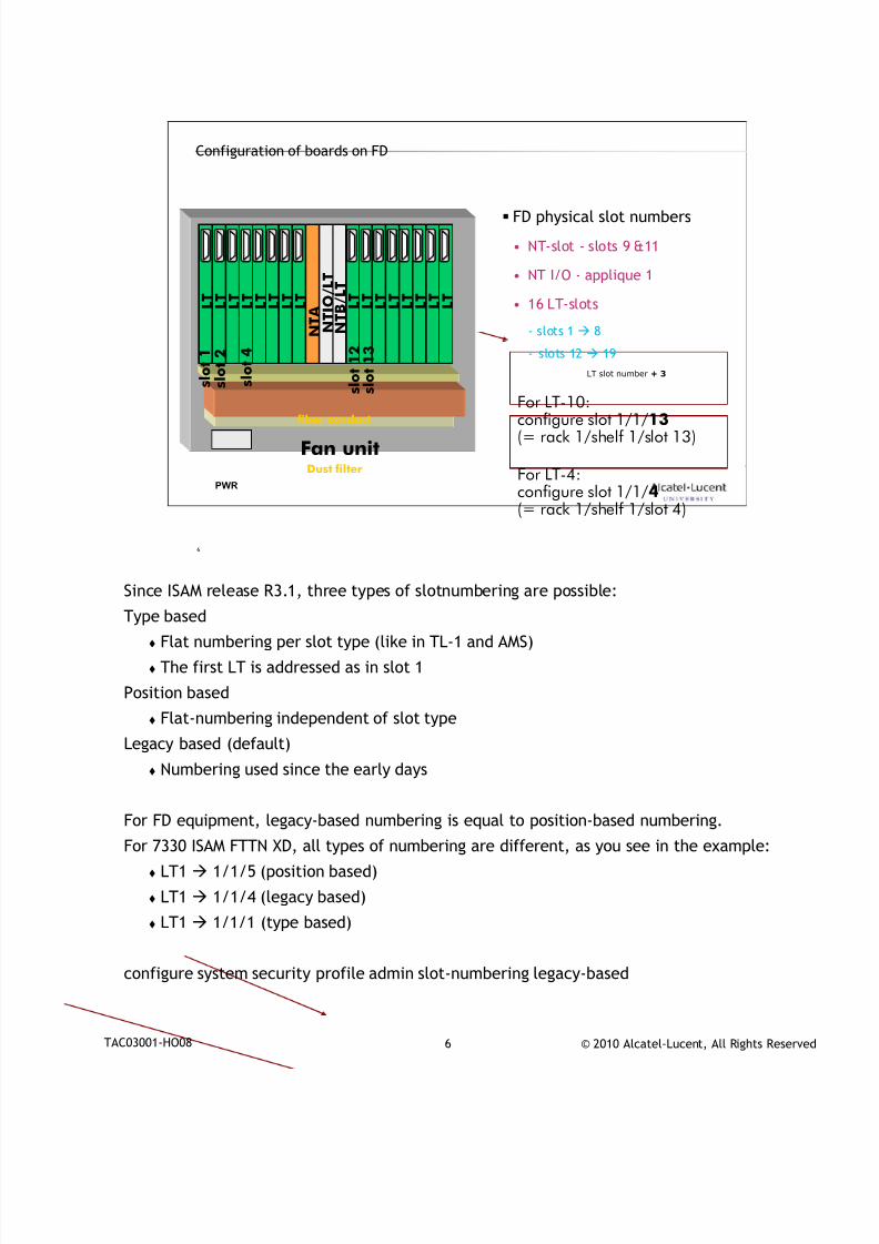
7/18/2019 Alu - A7302 Isam Fttu Operator Gpon Nant-e_ce-PDF
http://slidepdf.com/reader/full/alu-a7302-isam-fttu-operator-gpon-nant-ece-pdf 114/432
© 2010 Alcatel-Lucent, All Rights ReservedTAC03001-HO08 6
6
Configuration of boards on FD
L T L T L T L T L T L T
L T
L T L T L T L T L T L T L T L T
L T
N T A
N T B / L T
N T I O / L T
PWR
Dust filter
Fan unit
fiber conduct
FD physical slot numbers
• NT-slot - slots 9 &11
• NT I/O - applique 1
• 16 LT-slots
- slots 1 8
- slots 12 19
LT slot number + 3
s l o t 4
s l o t 1
s l o t 2
s l o t 1 2
s l o t 1 3
For LT-4:configure slot 1/1/4(= rack 1/shelf 1/slot 4)
For LT-10:configure slot 1/1/13
(= rack 1/shelf 1/slot 13)
Since ISAM release R3.1, three types of slotnumbering are possible:
Type based
Flat numbering per slot type (like in TL-1 and AMS)
The first LT is addressed as in slot 1
Position based
Flat-numbering independent of slot type
Legacy based (default)
Numbering used since the early days
For FD equipment, legacy-based numbering is equal to position-based numbering.
For 7330 ISAM FTTN XD, all types of numbering are different, as you see in the example:
LT1 1/1/5 (position based)
LT1 1/1/4 (legacy based)
LT1 1/1/1 (type based)
configure system security profile admin slot-numbering legacy-based
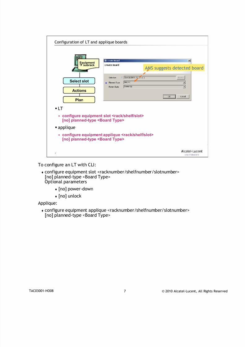
7/18/2019 Alu - A7302 Isam Fttu Operator Gpon Nant-e_ce-PDF
http://slidepdf.com/reader/full/alu-a7302-isam-fttu-operator-gpon-nant-ece-pdf 115/432
© 2010 Alcatel-Lucent, All Rights ReservedTAC03001-HO08 7
7
Configuration of LT and applique boards
LT
• configure equipment slot <rack/shelf/slot>[no] planned-type <Board Type>
applique
• configure equipment applique <rack/shelf/slot>[no] planned-type <Board Type>
Equipment
subrack
Select slot
Actions
Plan
AMS suggests detected board
To configure an LT with CLI:
configure equipment slot <racknumber/shelfnumber/slotnumber>[no] planned-type <Board Type>Optional parameters
[no] power-down
[no] unlock
Applique:
configure equipment applique <racknumber/shelfnumber/slotnumber>[no] planned-type <Board Type>
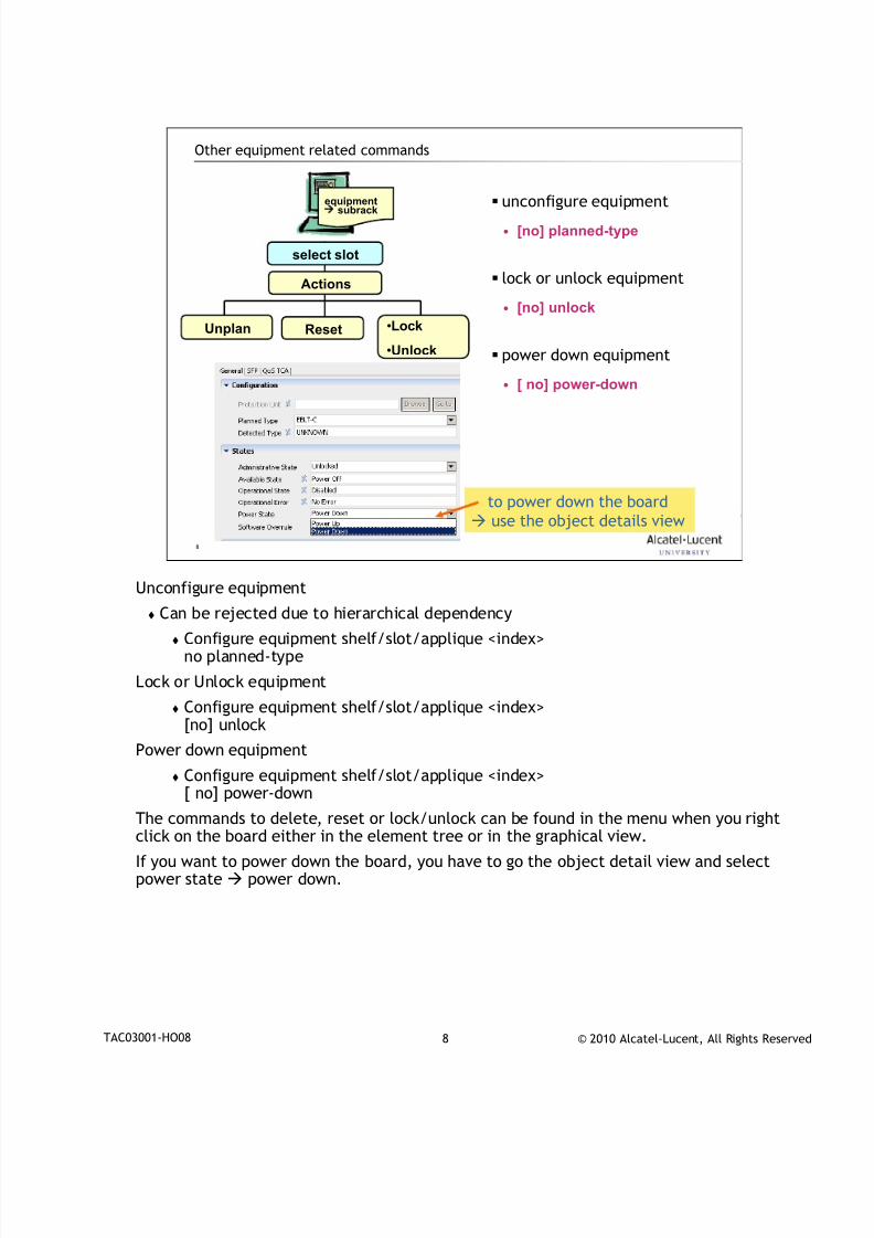
7/18/2019 Alu - A7302 Isam Fttu Operator Gpon Nant-e_ce-PDF
http://slidepdf.com/reader/full/alu-a7302-isam-fttu-operator-gpon-nant-ece-pdf 116/432
© 2010 Alcatel-Lucent, All Rights ReservedTAC03001-HO08 8
8
Other equipment related commands
unconfigure equipment
• [no] planned-type
lock or unlock equipment
• [no] unlock
power down equipment
• [ no] power-down
equipment subrack
select slot
Reset •Lock
•Unlock
Unplan
to power down the board
use the object details view
Actions
Unconfigure equipment
Can be rejected due to hierarchical dependency
Configure equipment shelf/slot/applique <index>no planned-type
Lock or Unlock equipment
Configure equipment shelf/slot/applique <index>[no] unlock
Power down equipment
Configure equipment shelf/slot/applique <index>[ no] power-down
The commands to delete, reset or lock/unlock can be found in the menu when you rightclick on the board either in the element tree or in the graphical view.
If you want to power down the board, you have to go the object detail view and selectpower state power down.
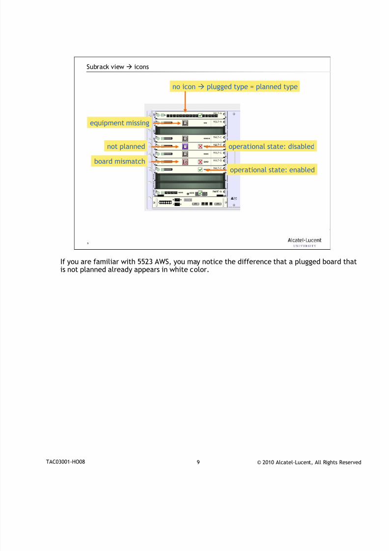
7/18/2019 Alu - A7302 Isam Fttu Operator Gpon Nant-e_ce-PDF
http://slidepdf.com/reader/full/alu-a7302-isam-fttu-operator-gpon-nant-ece-pdf 117/432
© 2010 Alcatel-Lucent, All Rights ReservedTAC03001-HO08 9
9
Subrack view icons
no icon
plugged type = planned type
not planned
equipment missing
board mismatch
operational state: disabled
operational state: enabled
If you are familiar with 5523 AWS, you may notice the difference that a plugged board that
is not planned already appears in white color.
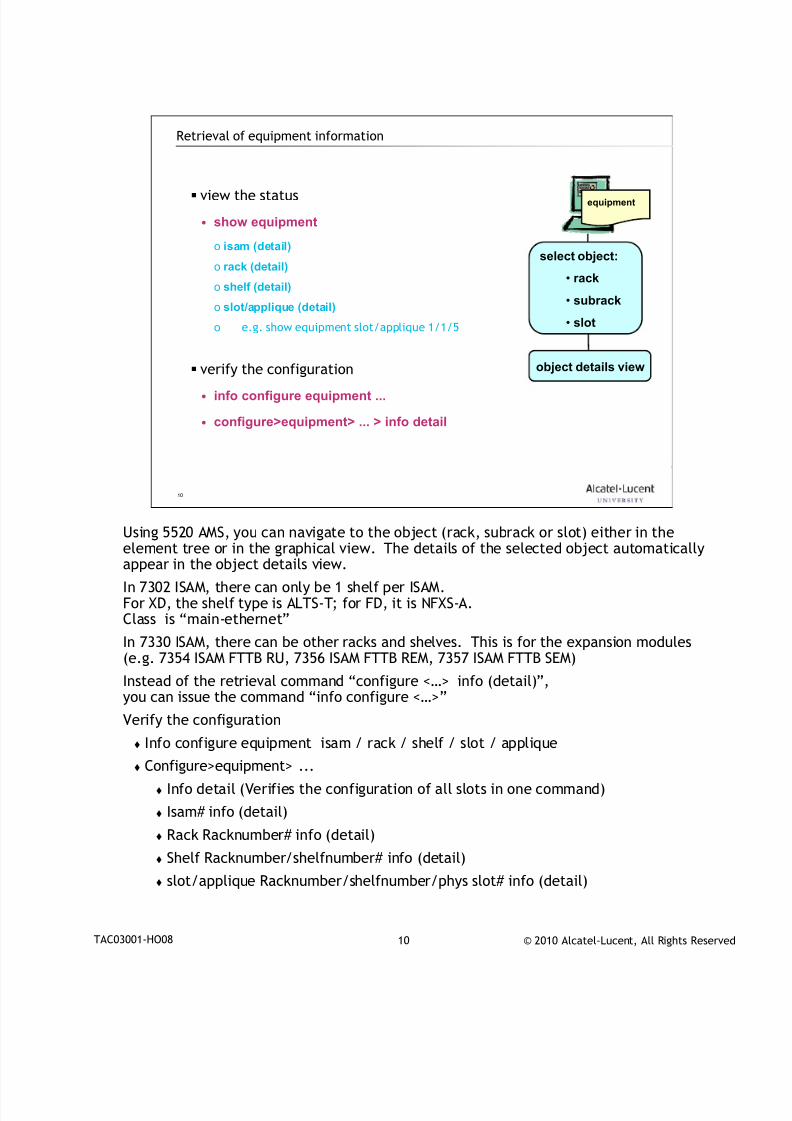
7/18/2019 Alu - A7302 Isam Fttu Operator Gpon Nant-e_ce-PDF
http://slidepdf.com/reader/full/alu-a7302-isam-fttu-operator-gpon-nant-ece-pdf 118/432
© 2010 Alcatel-Lucent, All Rights ReservedTAC03001-HO08 10
10
Retrieval of equipment information
view the status
• show equipment
o isam (detail)
o rack (detail)
o shelf (detail)
o slot/applique (detail)
o e.g. show equipment slot/applique 1/1/5
verify the configuration
• info configure equipment ...
• configure>equipment> ... > info detail
equipment
select object:
• rack
• subrack
• slot
object details view
Using 5520 AMS, you can navigate to the object (rack, subrack or slot) either in the
element tree or in the graphical view. The details of the selected object automaticallyappear in the object details view.
In 7302 ISAM, there can only be 1 shelf per ISAM.For XD, the shelf type is ALTS-T; for FD, it is NFXS-A.Class is “main-ethernet”
In 7330 ISAM, there can be other racks and shelves. This is for the expansion modules(e.g. 7354 ISAM FTTB RU, 7356 ISAM FTTB REM, 7357 ISAM FTTB SEM)
Instead of the retrieval command “configure <…> info (detail)”,you can issue the command “info configure <…>”
Verify the configuration
Info configure equipment isam / rack / shelf / slot / applique
Configure>equipment> ...
Info detail (Verifies the configuration of all slots in one command)
Isam# info (detail)
Rack Racknumber# info (detail)
Shelf Racknumber/shelfnumber# info (detail)
slot/applique Racknumber/shelfnumber/phys slot# info (detail)

7/18/2019 Alu - A7302 Isam Fttu Operator Gpon Nant-e_ce-PDF
http://slidepdf.com/reader/full/alu-a7302-isam-fttu-operator-gpon-nant-ece-pdf 119/432
© 2010 Alcatel-Lucent, All Rights ReservedTAC03001-HO08 11
11
www.alcatel-lucent.comwww.alcatel-lucent.com
7/18/2019 Alu - A7302 Isam Fttu Operator Gpon Nant-e_ce-PDF
http://slidepdf.com/reader/full/alu-a7302-isam-fttu-operator-gpon-nant-ece-pdf 120/432
© 2010 Alcatel-Lucent, All Rights ReservedDocument Number | Document Title 1
IHUB Basic Concepts and
Configuration
During class please switch off your mobile, pager or other that may interrupt.

7/18/2019 Alu - A7302 Isam Fttu Operator Gpon Nant-e_ce-PDF
http://slidepdf.com/reader/full/alu-a7302-isam-fttu-operator-gpon-nant-ece-pdf 121/432
© 2010 Alcatel-Lucent, All Rights ReservedDocument Number | Document Title 2
Objective
At the end of this chapter you will be able to:
Give an overview of IHUB concepts
Explain what a VPN service is
Explain what kind of services are supported on the new software
Give an overview of the supported forwarding models

7/18/2019 Alu - A7302 Isam Fttu Operator Gpon Nant-e_ce-PDF
http://slidepdf.com/reader/full/alu-a7302-isam-fttu-operator-gpon-nant-ece-pdf 122/432
© 2010 Alcatel-Lucent, All Rights ReservedDocument Number | Document Title 3
3
Introduction1
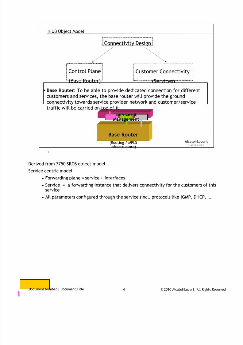
7/18/2019 Alu - A7302 Isam Fttu Operator Gpon Nant-e_ce-PDF
http://slidepdf.com/reader/full/alu-a7302-isam-fttu-operator-gpon-nant-ece-pdf 123/432
© 2010 Alcatel-Lucent, All Rights ReservedDocument Number | Document Title 4
4
IHUB Object Model
Base Router: To be able to provide dedicated connection for different
customers and services, the base router will provide the ground
connectivity towards service provider network and customer/service
traffic will be carried on top of it.
Customer Connectivity
(Services)
Control Plane
(Base Router)
Connectivity Design
Base Router
(Routing / MPLSInfrastructure)
Services &Management
Derived from 7750 SROS object model
Service centric model
Forwarding plane = service + interfaces
Service = a forwarding instance that delivers connectivity for the customers of thisservice
All parameters configured through the service (incl. protocols like IGMP, DHCP, …
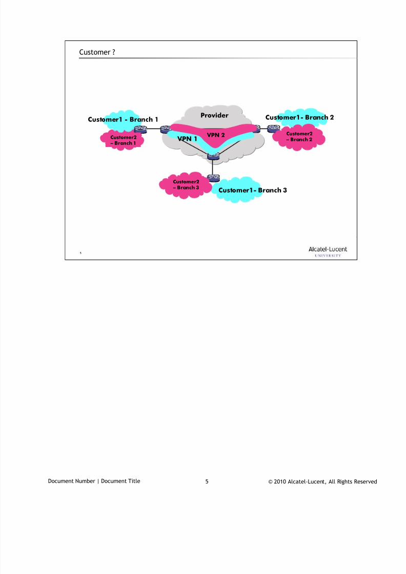
7/18/2019 Alu - A7302 Isam Fttu Operator Gpon Nant-e_ce-PDF
http://slidepdf.com/reader/full/alu-a7302-isam-fttu-operator-gpon-nant-ece-pdf 124/432
© 2010 Alcatel-Lucent, All Rights ReservedDocument Number | Document Title 5
5
Customer ?
Provider
VPN 1
Customer1 - Branch 1
VPN 2
Customer1- Branch 2
Customer1- Branch 3
Customer2– Branch 1
Customer2
– Branch 3
Customer2– Branch 2
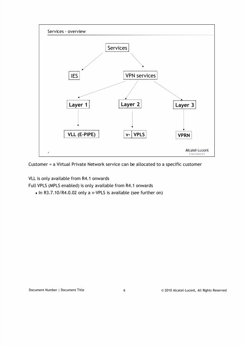
7/18/2019 Alu - A7302 Isam Fttu Operator Gpon Nant-e_ce-PDF
http://slidepdf.com/reader/full/alu-a7302-isam-fttu-operator-gpon-nant-ece-pdf 125/432
© 2010 Alcatel-Lucent, All Rights ReservedDocument Number | Document Title 6
6
Services - overview
VPN services
Layer 2 Layer 3
VLL (E-PIPE) VPLS VPRNv-
IES
Services
Layer 1
Customer = a Virtual Private Network service can be allocated to a specific customer
VLL is only available from R4.1 onwards
Full VPLS (MPLS enabled) is only available from R4.1 onwards
In R3.7.10/R4.0.02 only a v-VPLS is available (see further on)
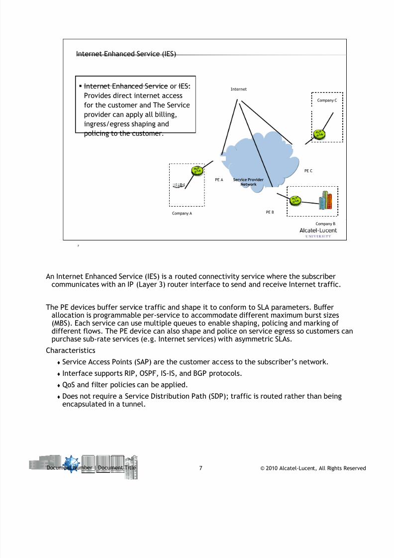
7/18/2019 Alu - A7302 Isam Fttu Operator Gpon Nant-e_ce-PDF
http://slidepdf.com/reader/full/alu-a7302-isam-fttu-operator-gpon-nant-ece-pdf 126/432
© 2010 Alcatel-Lucent, All Rights ReservedDocument Number | Document Title 7
7
Internet Enhanced Service or IES:
Provides direct internet access
for the customer and The Service
provider can apply all billing,
ingress/egress shaping and
policing to the customer.
Internet Enhanced Service (IES)
Service ProviderNetwork
Company A
Company C
Company B
PE A
PE C
PE B
Internet
An Internet Enhanced Service (IES) is a routed connectivity service where the subscribercommunicates with an IP (Layer 3) router interface to send and receive Internet traffic.
The PE devices buffer service traffic and shape it to conform to SLA parameters. Bufferallocation is programmable per-service to accommodate different maximum burst sizes(MBS). Each service can use multiple queues to enable shaping, policing and marking ofdifferent flows. The PE device can also shape and police on service egress so customers canpurchase sub-rate services (e.g. Internet services) with asymmetric SLAs.
Characteristics
Service Access Points (SAP) are the customer access to the subscriber’s network. Interface supports RIP, OSPF, IS-IS, and BGP protocols.
QoS and filter policies can be applied.
Does not require a Service Distribution Path (SDP); traffic is routed rather than beingencapsulated in a tunnel.
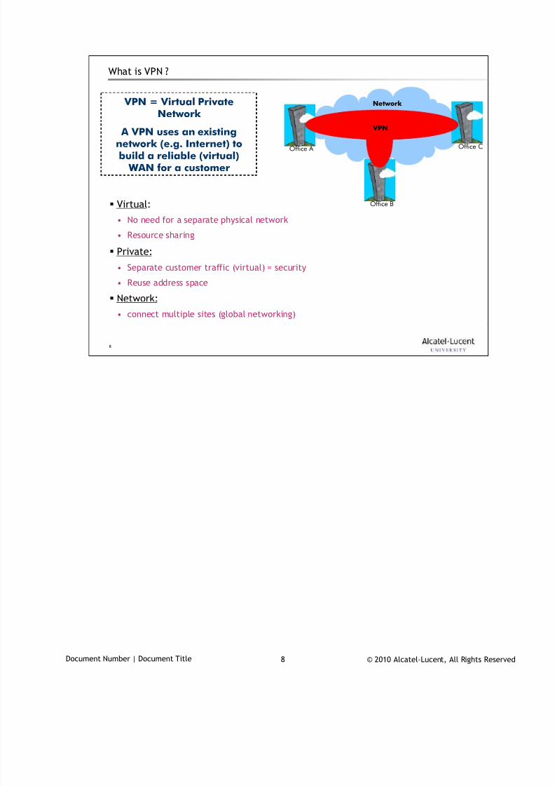
7/18/2019 Alu - A7302 Isam Fttu Operator Gpon Nant-e_ce-PDF
http://slidepdf.com/reader/full/alu-a7302-isam-fttu-operator-gpon-nant-ece-pdf 127/432
© 2010 Alcatel-Lucent, All Rights ReservedDocument Number | Document Title 8
8
What is VPN ?
Virtual:
• No need for a separate physical network
• Resource sharing
Private:• Separate customer traffic (virtual) = security
• Reuse address space
Network:
• connect multiple sites (global networking)
Network
Office A
Office B
Office C
VPN
VPN = Virtual PrivateNetwork
A VPN uses an existingnetwork (e.g. Internet) tobuild a reliable (virtual)
WAN for a customer
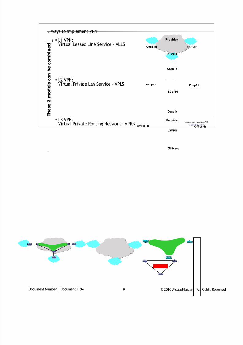
7/18/2019 Alu - A7302 Isam Fttu Operator Gpon Nant-e_ce-PDF
http://slidepdf.com/reader/full/alu-a7302-isam-fttu-operator-gpon-nant-ece-pdf 128/432
© 2010 Alcatel-Lucent, All Rights ReservedDocument Number | Document Title 9
9
3 ways to implement VPN
L1 VPN:Virtual Leased Line Service – VLLS
L2 VPN:Virtual Private Lan Service – VPLS
L3 VPN:Virtual Private Routing Network - VPRN
Provider
Corp1a Corp1b
Corp1c
L1 VPN
ProviderCorp1b
Corp1c
Corp1a
L2VPN
Provider
L3VPN
Office-bOffice-a
Office-c
T h
e s e 3 m o d e l s c a n b e c o m b i n e d
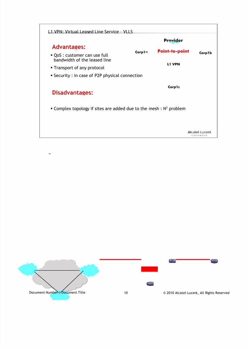
7/18/2019 Alu - A7302 Isam Fttu Operator Gpon Nant-e_ce-PDF
http://slidepdf.com/reader/full/alu-a7302-isam-fttu-operator-gpon-nant-ece-pdf 129/432
© 2010 Alcatel-Lucent, All Rights ReservedDocument Number | Document Title 10
10
L1 VPN: Virtual Leased Line Service – VLLS
QoS : customer can use fullbandwidth of the leased line
Transport of any protocol
Security : in case of P2P physical connection
Advantages:Prov ider
Corp1a Corp1b
Corp1c
L1 VPN
Complex topology if sites are added due to the mesh : N2 problem
Disadvantages:
Point-to-point
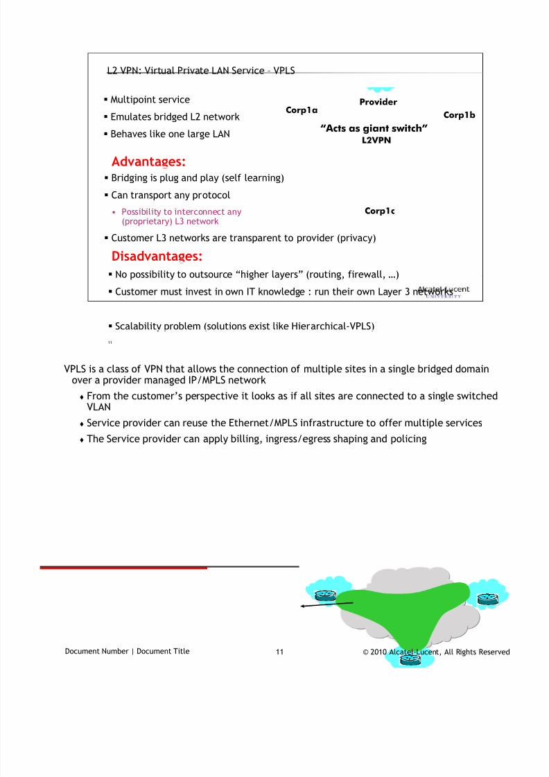
7/18/2019 Alu - A7302 Isam Fttu Operator Gpon Nant-e_ce-PDF
http://slidepdf.com/reader/full/alu-a7302-isam-fttu-operator-gpon-nant-ece-pdf 130/432
© 2010 Alcatel-Lucent, All Rights ReservedDocument Number | Document Title 11
11
L2 VPN: Virtual Private LAN Service – VPLS
Bridging is plug and play (self learning)
Can transport any protocol
• Possibility to interconnect any(proprietary) L3 network
Customer L3 networks are transparent to provider (privacy)
Advantages:
No possibility to outsource “higher layers” (routing, firewall, …)
Customer must invest in own IT knowledge : run their own Layer 3 networks
Scalability problem (solutions exist like Hierarchical-VPLS)
Disadvantages:
Provider
Corp1b
Corp1c
Corp1a
L2VPN
Multipoint service
Emulates bridged L2 network
Behaves like one large LAN “Acts as giant switch”
VPLS is a class of VPN that allows the connection of multiple sites in a single bridged domain
over a provider managed IP/MPLS network
From the customer’s perspective it looks as if all sites are connected to a single switchedVLAN
Service provider can reuse the Ethernet/MPLS infrastructure to offer multiple services
The Service provider can apply billing, ingress/egress shaping and policing
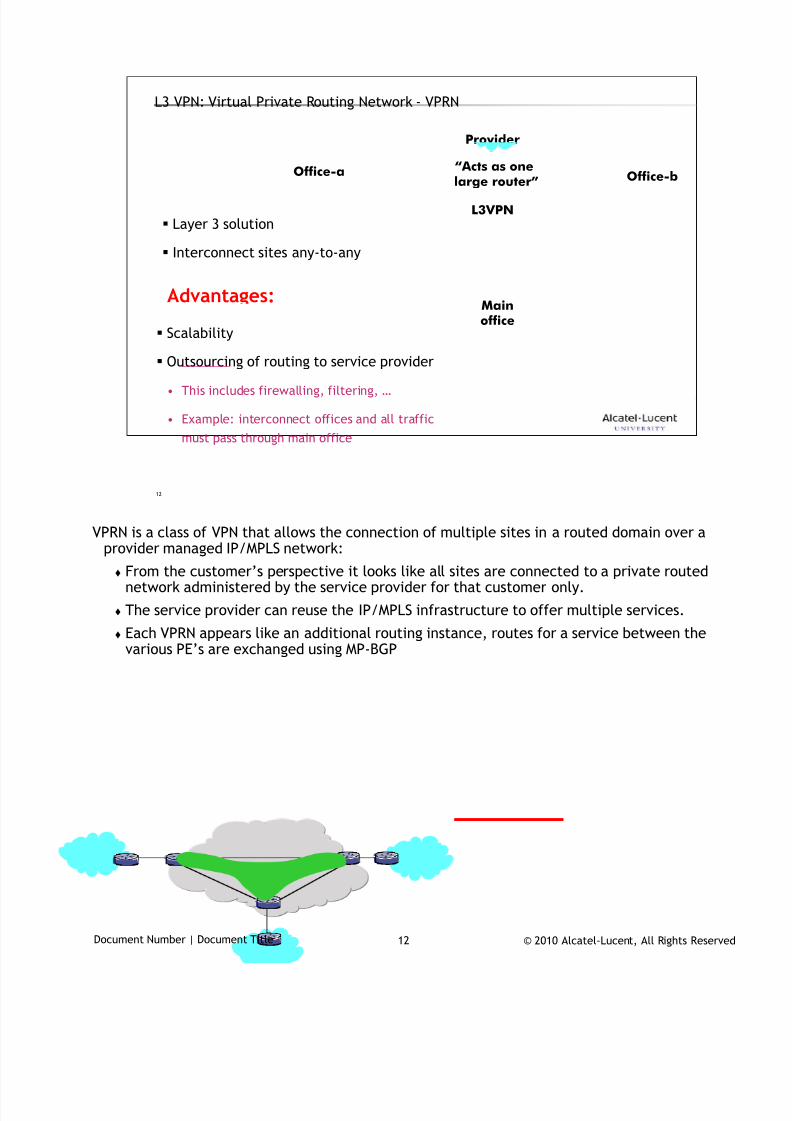
7/18/2019 Alu - A7302 Isam Fttu Operator Gpon Nant-e_ce-PDF
http://slidepdf.com/reader/full/alu-a7302-isam-fttu-operator-gpon-nant-ece-pdf 131/432
© 2010 Alcatel-Lucent, All Rights ReservedDocument Number | Document Title 12
12
L3 VPN: Virtual Private Routing Network - VPRN
Scalability
Outsourcing of routing to service provider
• This includes firewalling, filtering, …
• Example: interconnect offices and all traffic
must pass through main office
Advantages:
Provider
L3VPN
Office-b
Office-a
Mainoffice
“Acts as one
large router”
Layer 3 solution
Interconnect sites any-to-any
VPRN is a class of VPN that allows the connection of multiple sites in a routed domain over a
provider managed IP/MPLS network:
From the customer’s perspective it looks like all sites are connected to a private routednetwork administered by the service provider for that customer only.
The service provider can reuse the IP/MPLS infrastructure to offer multiple services.
Each VPRN appears like an additional routing instance, routes for a service between thevarious PE’s are exchanged using MP-BGP
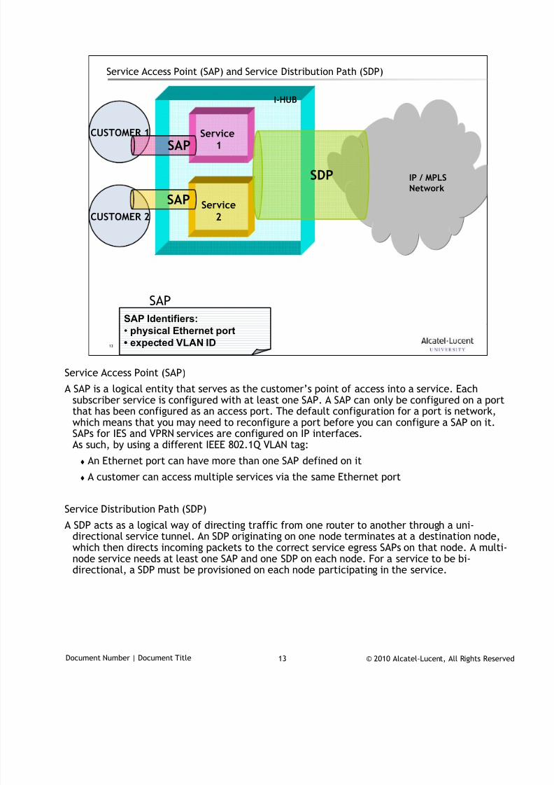
7/18/2019 Alu - A7302 Isam Fttu Operator Gpon Nant-e_ce-PDF
http://slidepdf.com/reader/full/alu-a7302-isam-fttu-operator-gpon-nant-ece-pdf 132/432
© 2010 Alcatel-Lucent, All Rights ReservedDocument Number | Document Title 13
13
CUSTOMER 2
Service Access Point (SAP) and Service Distribution Path (SDP)
SAP Identifiers:
• physical Ethernet port
• expected VLAN ID
Service1
CUSTOMER 1
I-HUB
Service2
IP / MPLSNetwork
SAP
SAP
SAP
SDP
Service Access Point (SAP)
A SAP is a logical entity that serves as the customer’s point of access into a service. Eachsubscriber service is configured with at least one SAP. A SAP can only be configured on a portthat has been configured as an access port. The default configuration for a port is network,which means that you may need to reconfigure a port before you can configure a SAP on it.SAPs for IES and VPRN services are configured on IP interfaces.As such, by using a different IEEE 802.1Q VLAN tag:
An Ethernet port can have more than one SAP defined on it
A customer can access multiple services via the same Ethernet port
Service Distribution Path (SDP)A SDP acts as a logical way of directing traffic from one router to another through a uni-
directional service tunnel. An SDP originating on one node terminates at a destination node,which then directs incoming packets to the correct service egress SAPs on that node. A multi-node service needs at least one SAP and one SDP on each node. For a service to be bi-directional, a SDP must be provisioned on each node participating in the service.
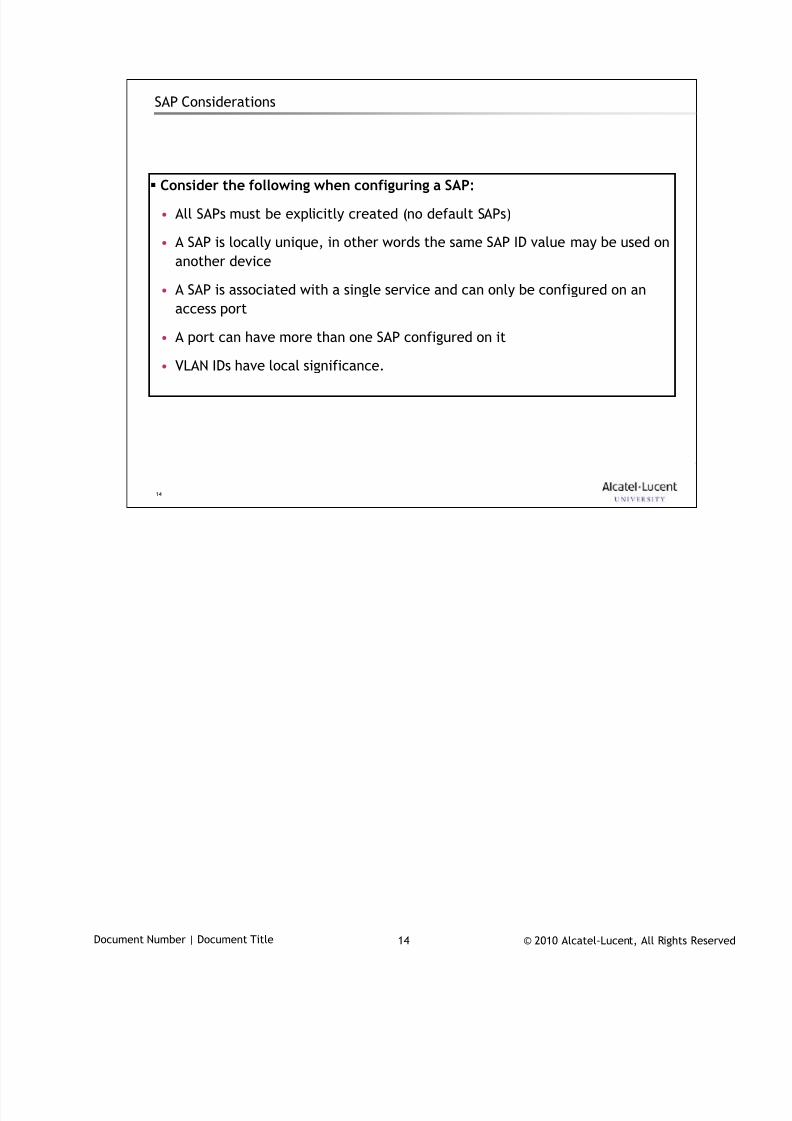
7/18/2019 Alu - A7302 Isam Fttu Operator Gpon Nant-e_ce-PDF
http://slidepdf.com/reader/full/alu-a7302-isam-fttu-operator-gpon-nant-ece-pdf 133/432
© 2010 Alcatel-Lucent, All Rights ReservedDocument Number | Document Title 14
14
SAP Considerations
Consider the following when configuring a SAP:
• All SAPs must be explicitly created (no default SAPs)
• A SAP is locally unique, in other words the same SAP ID value may be used on
another device
• A SAP is associated with a single service and can only be configured on an
access port
• A port can have more than one SAP configured on it
• VLAN IDs have local significance.
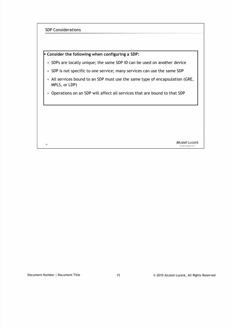
7/18/2019 Alu - A7302 Isam Fttu Operator Gpon Nant-e_ce-PDF
http://slidepdf.com/reader/full/alu-a7302-isam-fttu-operator-gpon-nant-ece-pdf 134/432
© 2010 Alcatel-Lucent, All Rights ReservedDocument Number | Document Title 15
15
SDP Considerations
Consider the following when configuring a SDP:
• SDPs are locally unique; the same SDP ID can be used on another device
• SDP is not specific to one service; many services can use the same SDP
• All services bound to an SDP must use the same type of encapsulation (GRE,
MPLS, or LDP)
• Operations on an SDP will affect all services that are bound to that SDP
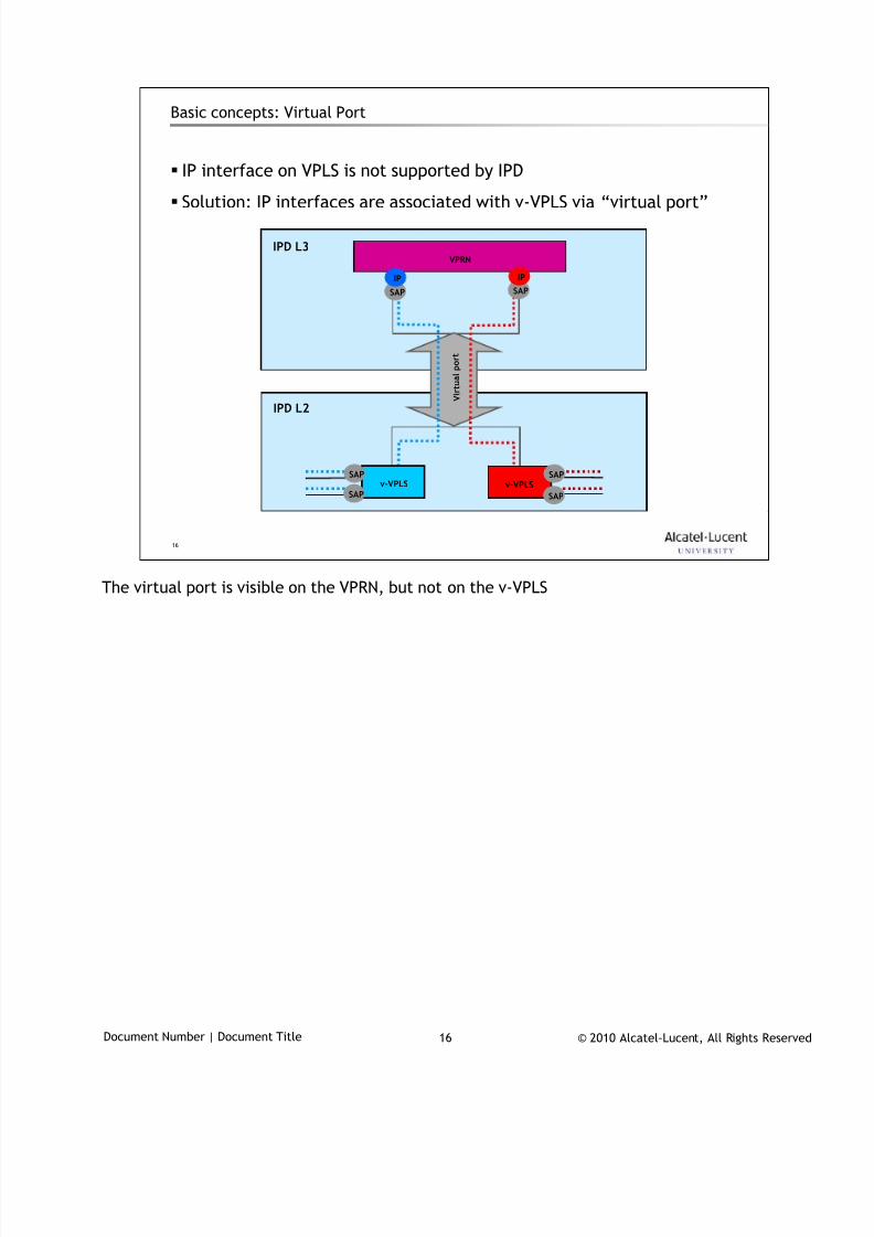
7/18/2019 Alu - A7302 Isam Fttu Operator Gpon Nant-e_ce-PDF
http://slidepdf.com/reader/full/alu-a7302-isam-fttu-operator-gpon-nant-ece-pdf 135/432
© 2010 Alcatel-Lucent, All Rights ReservedDocument Number | Document Title 16
16
Basic concepts: Virtual Port
IP interface on VPLS is not supported by IPD
Solution: IP interfaces are associated with v-VPLS via “virtual port”
V i r t u a l p o r t
IPD L2
IPD L3VPRN
SAP SAP
IPIP
v-VPLSSAP
SAP
SAP
SAP
v-VPLS
The virtual port is visible on the VPRN, but not on the v-VPLS
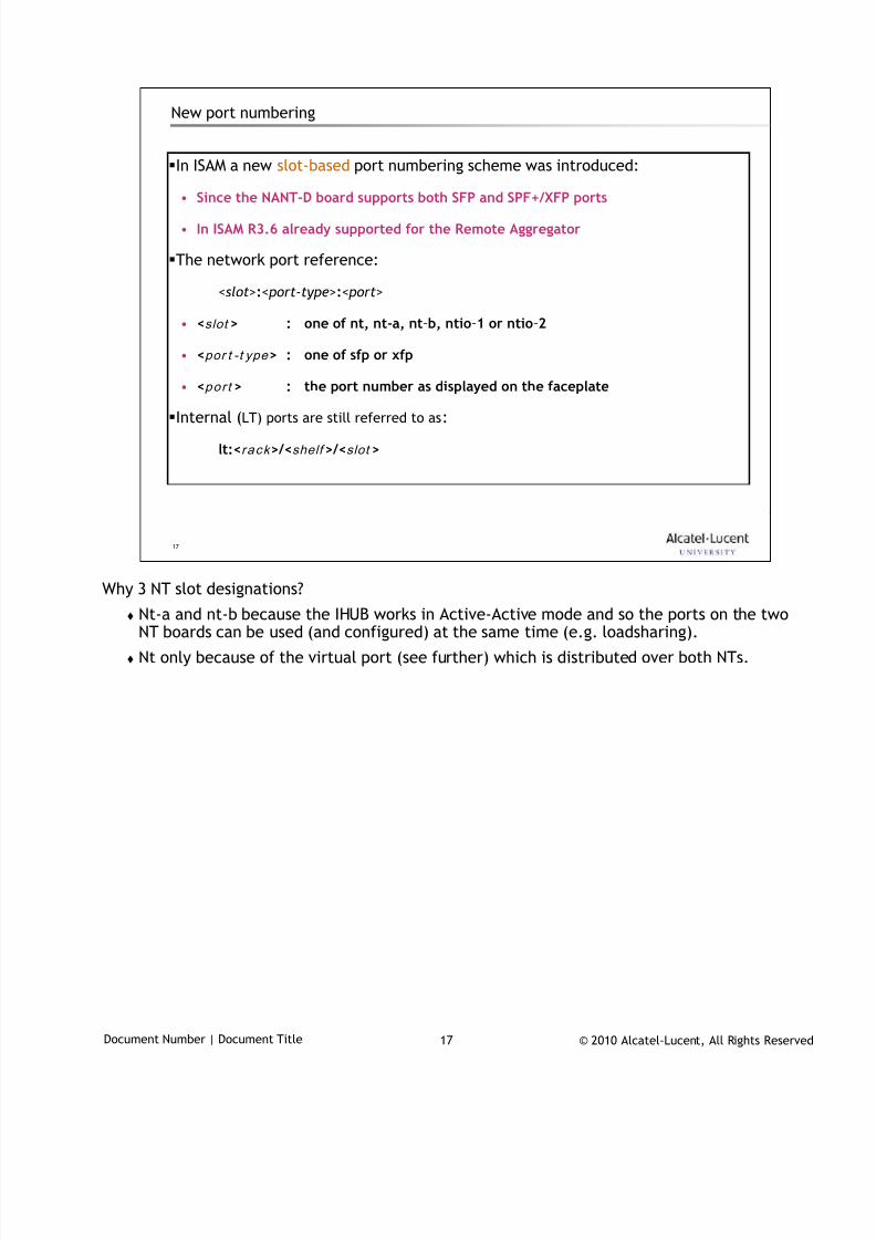
7/18/2019 Alu - A7302 Isam Fttu Operator Gpon Nant-e_ce-PDF
http://slidepdf.com/reader/full/alu-a7302-isam-fttu-operator-gpon-nant-ece-pdf 136/432
© 2010 Alcatel-Lucent, All Rights ReservedDocument Number | Document Title 17
17
New port numbering
In ISAM a new slot-based port numbering scheme was introduced:
• Since the NANT-D board supports both SFP and SPF+/XFP ports
• In ISAM R3.6 already supported for the Remote Aggregator
The network port reference:
<slot>:< port-type>:< port>
• <slot > : one of nt, nt-a, nt-b, ntio-1 or ntio-2
• <por t -t ype > : one of sfp or xfp
• <p o r t > : the port number as displayed on the faceplate
Internal (LT) ports are still referred to as:
lt:<r a c k >/<shelf >/<slot >
Why 3 NT slot designations?
Nt-a and nt-b because the IHUB works in Active-Active mode and so the ports on the twoNT boards can be used (and configured) at the same time (e.g. loadsharing).
Nt only because of the virtual port (see further) which is distributed over both NTs.
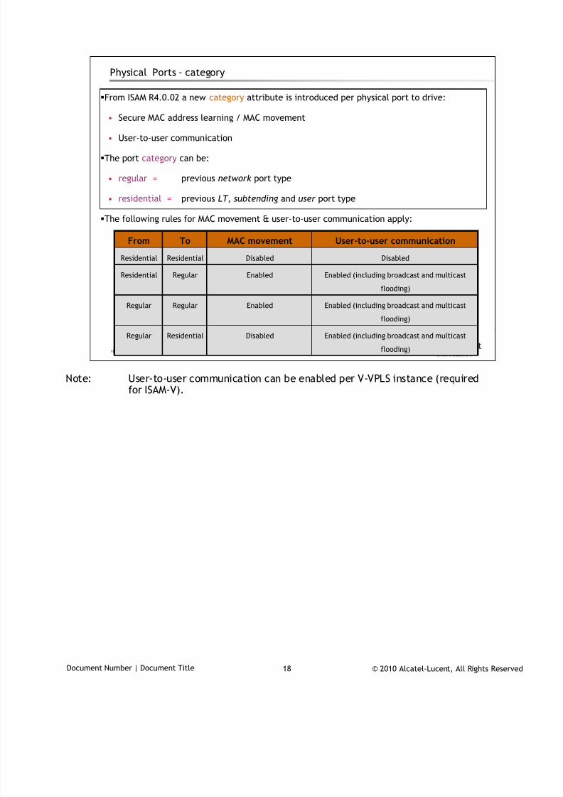
7/18/2019 Alu - A7302 Isam Fttu Operator Gpon Nant-e_ce-PDF
http://slidepdf.com/reader/full/alu-a7302-isam-fttu-operator-gpon-nant-ece-pdf 137/432
© 2010 Alcatel-Lucent, All Rights ReservedDocument Number | Document Title 18
18
Physical Ports - category
From ISAM R4.0.02 a new category attribute is introduced per physical port to drive:
• Secure MAC address learning / MAC movement
• User-to-user communication
The port category can be:
• regular = previous network port type
• residential = previous LT , subtending and user port type
The following rules for MAC movement & user-to-user communication apply:
Disabled
Enabled
Enabled
Disabled
MAC movement
Enabled (including broadcast and multicast
flooding)
RegularResidential
Residential
Regular
Residential
To
Enabled (including broadcast and multicast
flooding)
Regular
Enabled (including broadcast and multicast
flooding)
Regular
DisabledResidential
User-to-user communicationFrom
Note: User-to-user communication can be enabled per V-VPLS instance (required
for ISAM-V).
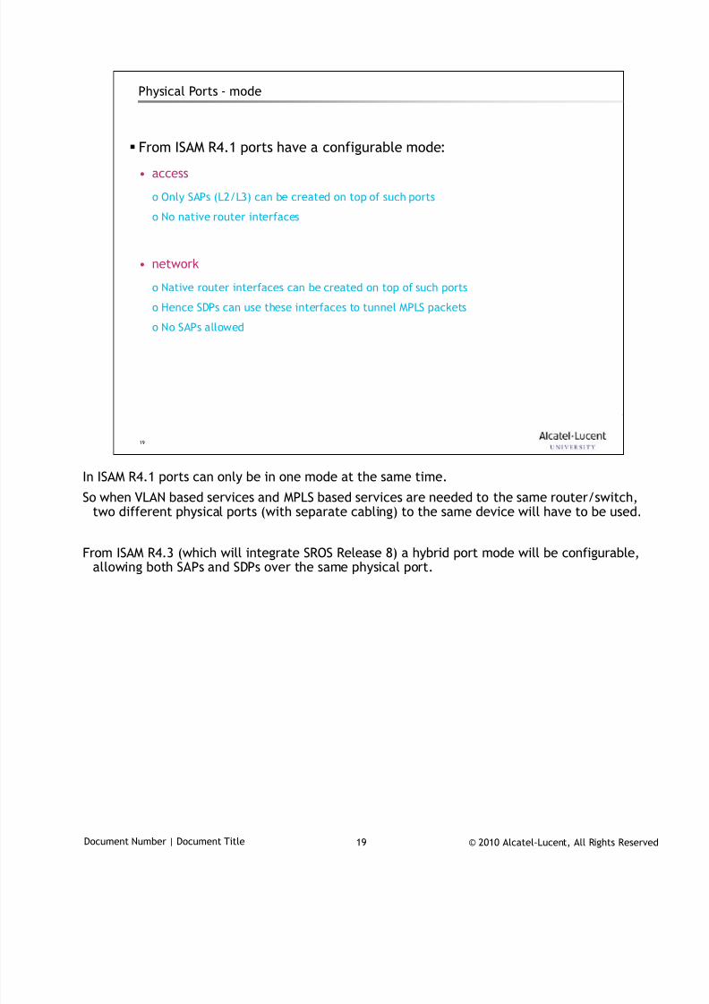
7/18/2019 Alu - A7302 Isam Fttu Operator Gpon Nant-e_ce-PDF
http://slidepdf.com/reader/full/alu-a7302-isam-fttu-operator-gpon-nant-ece-pdf 138/432
© 2010 Alcatel-Lucent, All Rights ReservedDocument Number | Document Title 19
19
Physical Ports - mode
From ISAM R4.1 ports have a configurable mode:
• access
o Only SAPs (L2/L3) can be created on top of such ports
o No native router interfaces
• network
o Native router interfaces can be created on top of such ports
o Hence SDPs can use these interfaces to tunnel MPLS packets
o No SAPs allowed
In ISAM R4.1 ports can only be in one mode at the same time.
So when VLAN based services and MPLS based services are needed to the same router/switch,two different physical ports (with separate cabling) to the same device will have to be used.
From ISAM R4.3 (which will integrate SROS Release 8) a hybrid port mode will be configurable,allowing both SAPs and SDPs over the same physical port.
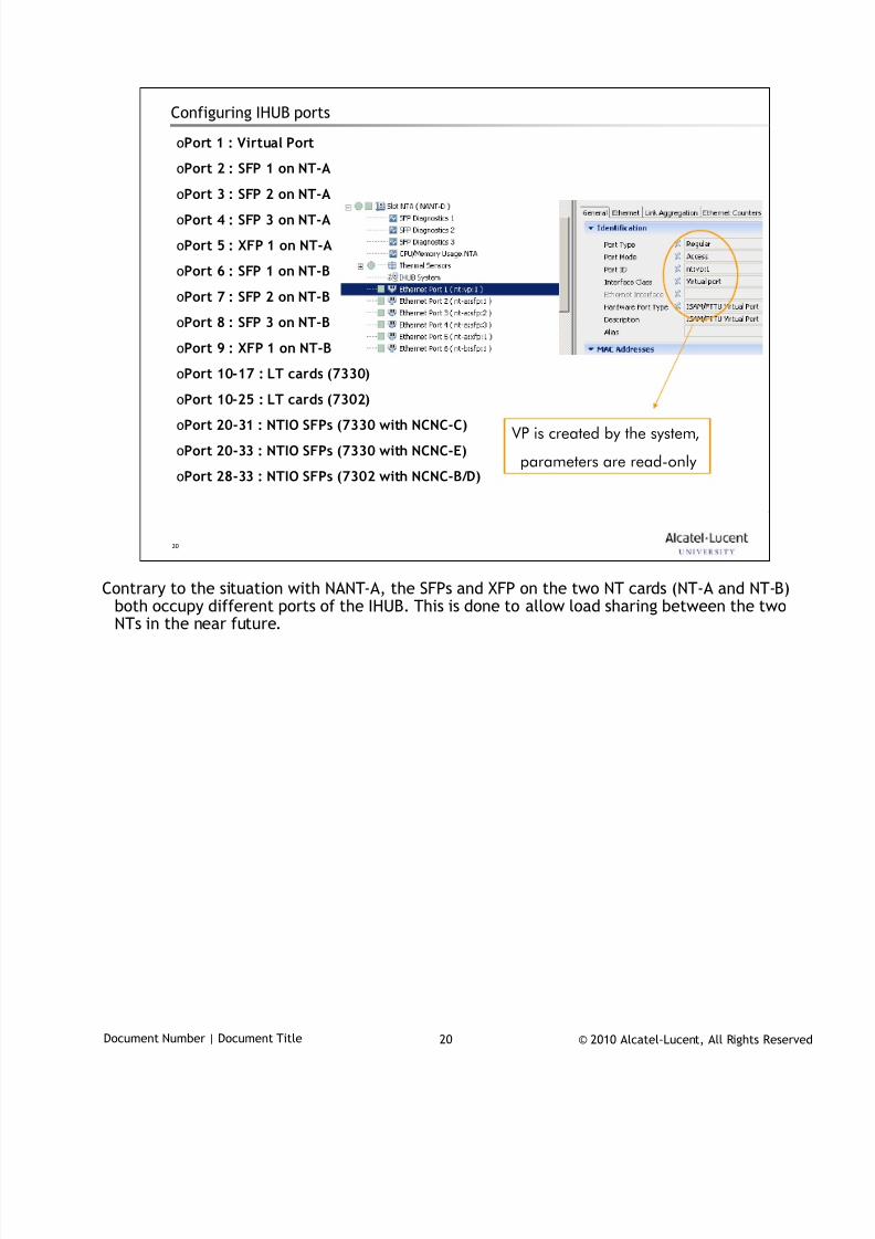
7/18/2019 Alu - A7302 Isam Fttu Operator Gpon Nant-e_ce-PDF
http://slidepdf.com/reader/full/alu-a7302-isam-fttu-operator-gpon-nant-ece-pdf 139/432
© 2010 Alcatel-Lucent, All Rights ReservedDocument Number | Document Title 20
20
Configuring IHUB ports
VP is created by the system,
parameters are read-only
oPort 1 : Virtual Port
oPort 2 : SFP 1 on NT-A
oPort 3 : SFP 2 on NT-AoPort 4 : SFP 3 on NT-A
oPort 5 : XFP 1 on NT-A
oPort 6 : SFP 1 on NT-B
oPort 7 : SFP 2 on NT-B
oPort 8 : SFP 3 on NT-B
oPort 9 : XFP 1 on NT-B
oPort 10-17 : LT cards (7330)
oPort 10-25 : LT cards (7302)oPort 20-31 : NTIO SFPs (7330 with NCNC-C)
oPort 20-33 : NTIO SFPs (7330 with NCNC-E)
oPort 28-33 : NTIO SFPs (7302 with NCNC-B/D)
Contrary to the situation with NANT-A, the SFPs and XFP on the two NT cards (NT-A and NT-B)
both occupy different ports of the IHUB. This is done to allow load sharing between the twoNTs in the near future.
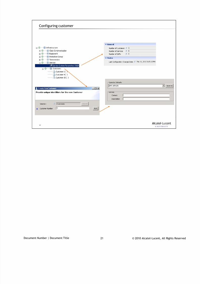
7/18/2019 Alu - A7302 Isam Fttu Operator Gpon Nant-e_ce-PDF
http://slidepdf.com/reader/full/alu-a7302-isam-fttu-operator-gpon-nant-ece-pdf 140/432
© 2010 Alcatel-Lucent, All Rights ReservedDocument Number | Document Title 21
21
Configuring customer

7/18/2019 Alu - A7302 Isam Fttu Operator Gpon Nant-e_ce-PDF
http://slidepdf.com/reader/full/alu-a7302-isam-fttu-operator-gpon-nant-ece-pdf 141/432
© 2010 Alcatel-Lucent, All Rights ReservedDocument Number | Document Title 22
22
www.alcatel-lucent.comwww.alcatel-lucent.com
7/18/2019 Alu - A7302 Isam Fttu Operator Gpon Nant-e_ce-PDF
http://slidepdf.com/reader/full/alu-a7302-isam-fttu-operator-gpon-nant-ece-pdf 142/432
© 2010 Alcatel-Lucent, All Rights ReservedTAC03049 | GPON technology 1
PON
Passive Optical Networking
During class please switch off your mobile, pager or other that may interrupt.

7/18/2019 Alu - A7302 Isam Fttu Operator Gpon Nant-e_ce-PDF
http://slidepdf.com/reader/full/alu-a7302-isam-fttu-operator-gpon-nant-ece-pdf 143/432
© 2010 Alcatel-Lucent, All Rights ReservedTAC03049 | GPON technology 2
Objective
At the end of the course, you’ll be able to …
understand how fibers work, and explain which components are used in an
optical relay system
• internal reflection, transmitter, amplifier, receiver, splitter, …
explain the basic properties of a passive optical network
describe the functions of the components present in a PON based network
correctly use basic PON terminology
7/18/2019 Alu - A7302 Isam Fttu Operator Gpon Nant-e_ce-PDF
http://slidepdf.com/reader/full/alu-a7302-isam-fttu-operator-gpon-nant-ece-pdf 144/432
© 2010 Alcatel-Lucent, All Rights ReservedTAC03049 | GPON technology 3
3
Table of Contents
Optical fiber fundamentals
PON standardisation
GPON fundamentals
7/18/2019 Alu - A7302 Isam Fttu Operator Gpon Nant-e_ce-PDF
http://slidepdf.com/reader/full/alu-a7302-isam-fttu-operator-gpon-nant-ece-pdf 145/432
© 2010 Alcatel-Lucent, All Rights ReservedTAC03049 | GPON technology 4
4
Optical Fiber Fundamentals1
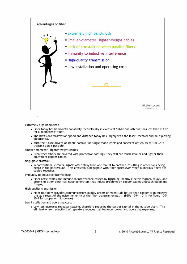
7/18/2019 Alu - A7302 Isam Fttu Operator Gpon Nant-e_ce-PDF
http://slidepdf.com/reader/full/alu-a7302-isam-fttu-operator-gpon-nant-ece-pdf 146/432
© 2010 Alcatel-Lucent, All Rights ReservedTAC03049 | GPON technology 5
5
Advantages of fiber
Extremely high bandwidth
Smaller-diameter, lighter-weight cables
Lack of crosstalk between parallel fibers
Immunity to inductive interference
High-quality transmission
Low installation and operating costs
Extremely high bandwidth
Fiber today has bandwidth capability theoretically in excess of 10Ghz and attenuations less than 0.3 dbfor a kilometer of fiber.
The limits on transmission speed and distance today lies largely with the laser, receiver and multiplexingelectronics.
With the future advent of stable narrow line single-mode lasers and coherent optics, 10 to 100 Gb/stransmission is possible.
Smaller diameter – lighter weight cables
Even when fibers are covered with protective coatings, they still are much smaller and lighter thanequivalent copper cables.
Negligible crosstalk
In conventional circuits, signals often stray from one circuit to another, resulting in other calls beingheard in the background. This crosstalk is negligible with fiber optics even when numerous fibers are
cabled together.Immunity to inductive interference
Fiber optic cables are immune to interference caused by lightning, nearby electric motors, relays, anddozens of other electrical noise generators that induce problems on copper cables unless shielded andfiltered.
High quality transmission
Fiber routinely provides communications quality orders of magnitude better than copper or microwave,this as a result of the noise immunity of the fiber transmission path. (BER: 10-9 – 10-11 for fiber, 10-5 –10-7 for copper or microwave)
Low installation and operating costs
Low loss increases repeater spacing, therefore reducing the cost of capital in the outside plant. Theelimination (or reduction) of repeaters reduces maintenance, power and operating expenses.
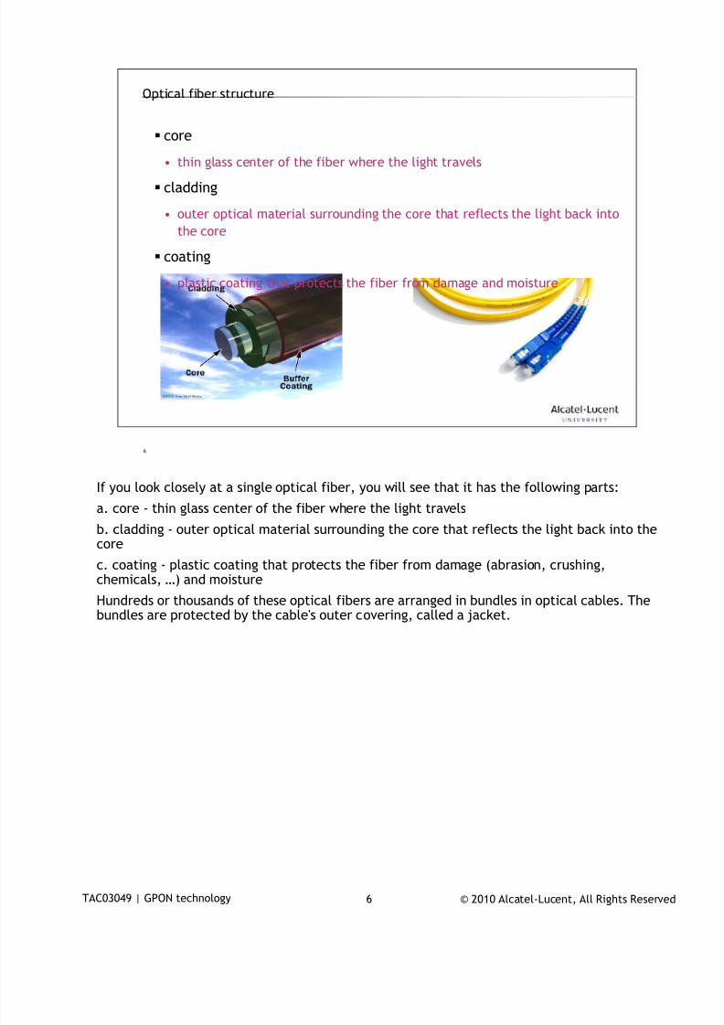
7/18/2019 Alu - A7302 Isam Fttu Operator Gpon Nant-e_ce-PDF
http://slidepdf.com/reader/full/alu-a7302-isam-fttu-operator-gpon-nant-ece-pdf 147/432
© 2010 Alcatel-Lucent, All Rights ReservedTAC03049 | GPON technology 6
6
Optical fiber structure
core
• thin glass center of the fiber where the light travels
cladding
• outer optical material surrounding the core that reflects the light back into
the core
coating
• plastic coating that protects the fiber from damage and moisture
If you look closely at a single optical fiber, you will see that it has the following parts:
a. core - thin glass center of the fiber where the light travels
b. cladding - outer optical material surrounding the core that reflects the light back into thecore
c. coating - plastic coating that protects the fiber from damage (abrasion, crushing,chemicals, …) and moisture
Hundreds or thousands of these optical fibers are arranged in bundles in optical cables. Thebundles are protected by the cable's outer covering, called a jacket.
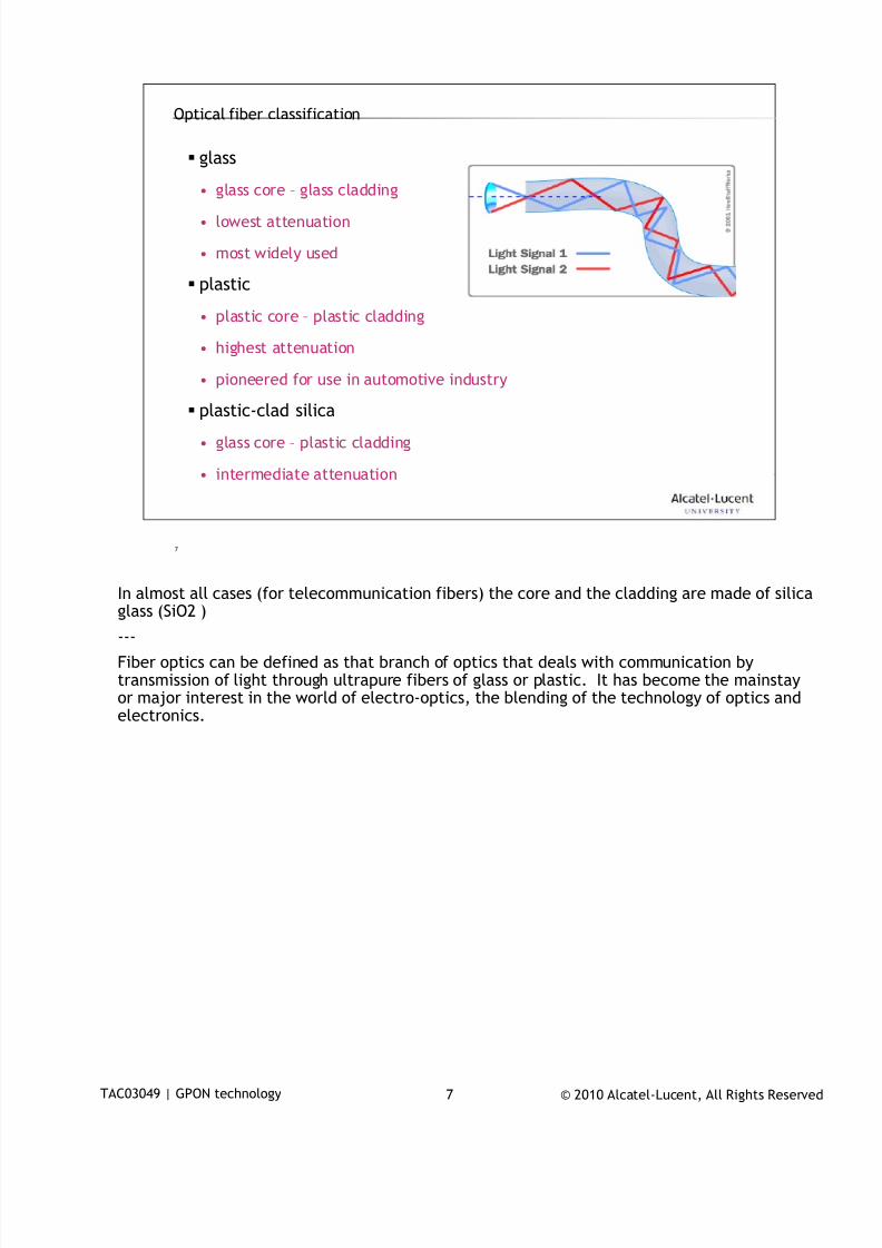
7/18/2019 Alu - A7302 Isam Fttu Operator Gpon Nant-e_ce-PDF
http://slidepdf.com/reader/full/alu-a7302-isam-fttu-operator-gpon-nant-ece-pdf 148/432
© 2010 Alcatel-Lucent, All Rights ReservedTAC03049 | GPON technology 7
7
Optical fiber classification
glass
• glass core – glass cladding
• lowest attenuation
• most widely used
plastic
• plastic core – plastic cladding
• highest attenuation
• pioneered for use in automotive industry
plastic-clad silica
• glass core – plastic cladding
• intermediate attenuation
In almost all cases (for telecommunication fibers) the core and the cladding are made of silica
glass (SiO2 )
---
Fiber optics can be defined as that branch of optics that deals with communication bytransmission of light through ultrapure fibers of glass or plastic. It has become the mainstayor major interest in the world of electro-optics, the blending of the technology of optics andelectronics.
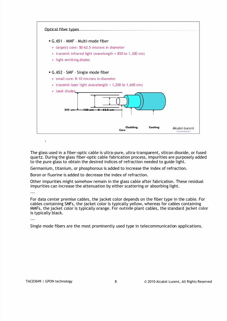
7/18/2019 Alu - A7302 Isam Fttu Operator Gpon Nant-e_ce-PDF
http://slidepdf.com/reader/full/alu-a7302-isam-fttu-operator-gpon-nant-ece-pdf 149/432
© 2010 Alcatel-Lucent, All Rights ReservedTAC03049 | GPON technology 8
8
Optical fiber types
G.651 – MMF – Multi-mode fiber
• large(r) core: 50-62.5 microns in diameter
• transmit infrared light (wavelength = 850 to 1,300 nm)
• light-emitting diodes
G.652 – SMF – Single mode fiber
• small core: 8-10 microns in diameter
• transmit laser light (wavelength = 1,200 to 1,600 nm)
• laser diodes
8 – 62.5 um125 um
CladdingCore
Coating
245 um
The glass used in a fiber-optic cable is ultra-pure, ultra-transparent, silicon dioxide, or fused
quartz. During the glass fiber-optic cable fabrication process, impurities are purposely addedto the pure glass to obtain the desired indices of refraction needed to guide light.
Germanium, titanium, or phosphorous is added to increase the index of refraction.
Boron or fluorine is added to decrease the index of refraction.
Other impurities might somehow remain in the glass cable after fabrication. These residualimpurities can increase the attenuation by either scattering or absorbing light.
---
For data center premise cables, the jacket color depends on the fiber type in the cable. Forcables containing SMFs, the jacket color is typically yellow, whereas for cables containing
MMFs, the jacket color is typically orange. For outside plant cables, the standard jacket coloris typically black.
---
Single mode fibers are the most prominently used type in telecommunication applications.
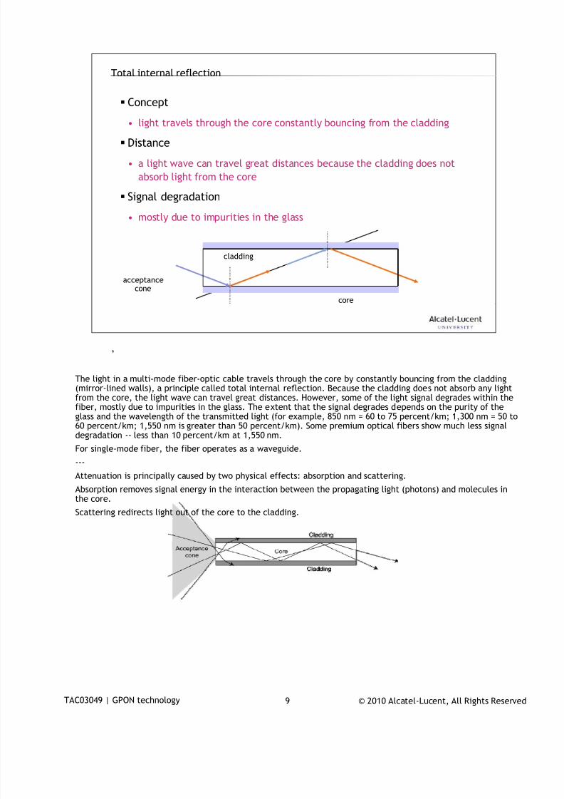
7/18/2019 Alu - A7302 Isam Fttu Operator Gpon Nant-e_ce-PDF
http://slidepdf.com/reader/full/alu-a7302-isam-fttu-operator-gpon-nant-ece-pdf 150/432
© 2010 Alcatel-Lucent, All Rights ReservedTAC03049 | GPON technology 9
9
Total internal reflection
Concept
• light travels through the core constantly bouncing from the cladding
Distance
• a light wave can travel great distances because the cladding does not
absorb light from the core
Signal degradation
• mostly due to impurities in the glass
core
cladding
acceptancecone
The light in a multi-mode fiber-optic cable travels through the core by constantly bouncing from the cladding
(mirror-lined walls), a principle called total internal reflection. Because the cladding does not absorb any lightfrom the core, the light wave can travel great distances. However, some of the light signal degrades within thefiber, mostly due to impurities in the glass. The extent that the signal degrades depends on the purity of theglass and the wavelength of the transmitted light (for example, 850 nm = 60 to 75 percent/km; 1,300 nm = 50 to60 percent/km; 1,550 nm is greater than 50 percent/km). Some premium optical fibers show much less signaldegradation -- less than 10 percent/km at 1,550 nm.
For single-mode fiber, the fiber operates as a waveguide.
---
Attenuation is principally caused by two physical effects: absorption and scattering.
Absorption removes signal energy in the interaction between the propagating light (photons) and molecules inthe core.
Scattering redirects light out of the core to the cladding.
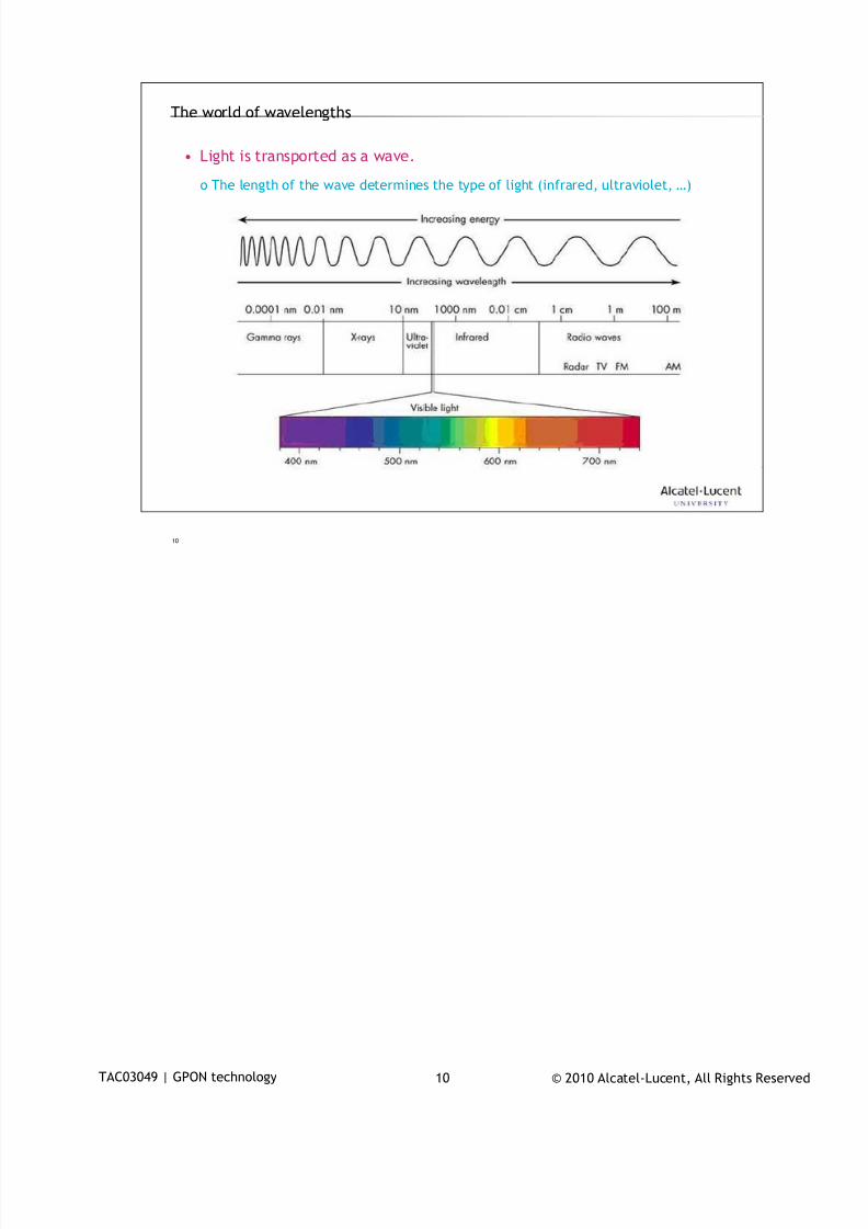
7/18/2019 Alu - A7302 Isam Fttu Operator Gpon Nant-e_ce-PDF
http://slidepdf.com/reader/full/alu-a7302-isam-fttu-operator-gpon-nant-ece-pdf 151/432
© 2010 Alcatel-Lucent, All Rights ReservedTAC03049 | GPON technology 10
10
The world of wavelengths
• Light is transported as a wave.
o The length of the wave determines the type of light (infrared, ultraviolet, …)
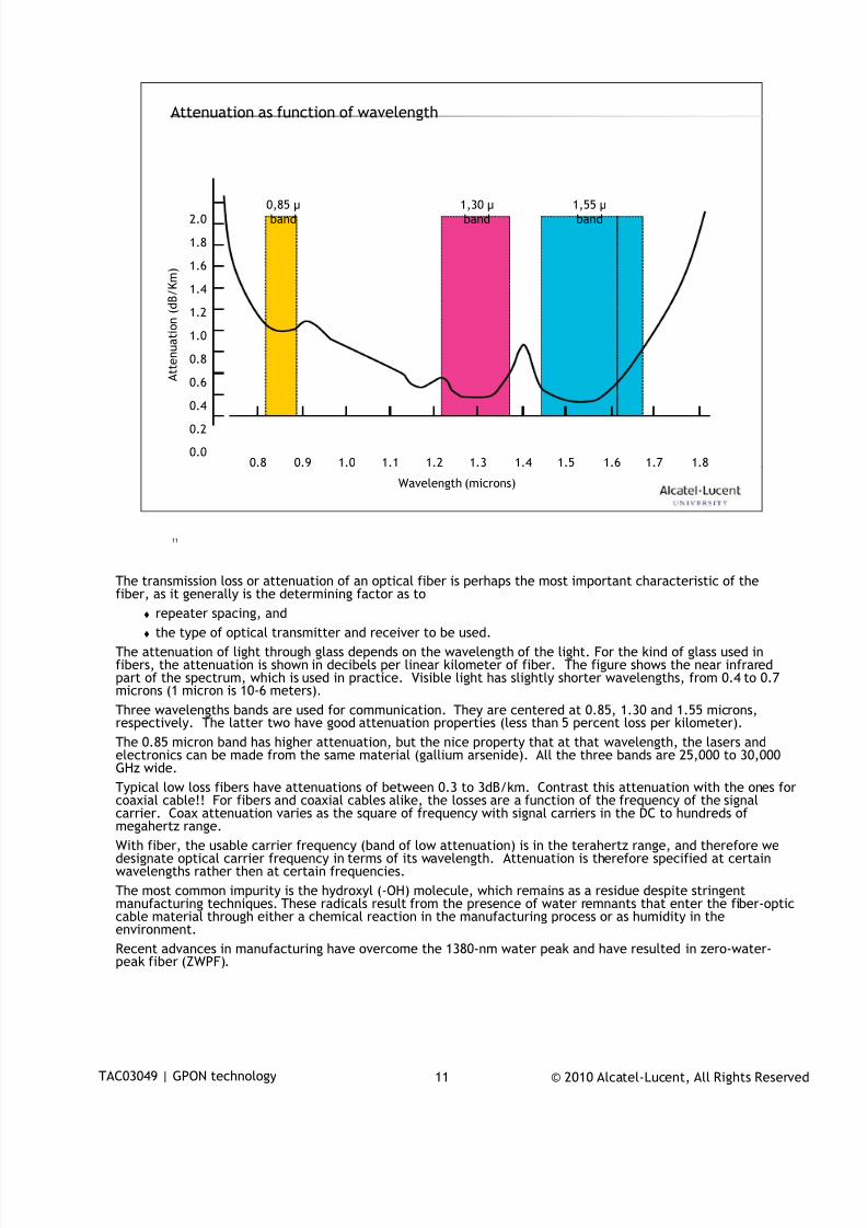
7/18/2019 Alu - A7302 Isam Fttu Operator Gpon Nant-e_ce-PDF
http://slidepdf.com/reader/full/alu-a7302-isam-fttu-operator-gpon-nant-ece-pdf 152/432
© 2010 Alcatel-Lucent, All Rights ReservedTAC03049 | GPON technology 11
11
Attenuation as function of wavelength
0.8 0.9 1.0 1.1 1.2 1.3 1.4 1.5 1.6 1.8
Wavelength (microns)
1.7
2.0
0.2
0.4
0.6
0.8
1.0
1.2
1.4
1.6
1.8
A t t e n u a t i o n ( d B / K m )
0,85 µband
1,30 µband
1,55 µband
0.0
The transmission loss or attenuation of an optical fiber is perhaps the most important characteristic of the
fiber, as it generally is the determining factor as to repeater spacing, and
the type of optical transmitter and receiver to be used.
The attenuation of light through glass depends on the wavelength of the light. For the kind of glass used infibers, the attenuation is shown in decibels per linear kilometer of fiber. The figure shows the near infraredpart of the spectrum, which is used in practice. Visible light has slightly shorter wavelengths, from 0.4 to 0.7microns (1 micron is 10-6 meters).
Three wavelengths bands are used for communication. They are centered at 0.85, 1.30 and 1.55 microns,respectively. The latter two have good attenuation properties (less than 5 percent loss per kilometer).
The 0.85 micron band has higher attenuation, but the nice property that at that wavelength, the lasers andelectronics can be made from the same material (gallium arsenide). All the three bands are 25,000 to 30,000GHz wide.
Typical low loss fibers have attenuations of between 0.3 to 3dB/km. Contrast this attenuation with the ones for
coaxial cable!! For fibers and coaxial cables alike, the losses are a function of the frequency of the signalcarrier. Coax attenuation varies as the square of frequency with signal carriers in the DC to hundreds ofmegahertz range.
With fiber, the usable carrier frequency (band of low attenuation) is in the terahertz range, and therefore wedesignate optical carrier frequency in terms of its wavelength. Attenuation is therefore specified at certainwavelengths rather then at certain frequencies.
The most common impurity is the hydroxyl (-OH) molecule, which remains as a residue despite stringentmanufacturing techniques. These radicals result from the presence of water remnants that enter the fiber-opticcable material through either a chemical reaction in the manufacturing process or as humidity in theenvironment.
Recent advances in manufacturing have overcome the 1380-nm water peak and have resulted in zero-water-peak fiber (ZWPF).
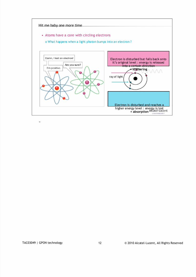
7/18/2019 Alu - A7302 Isam Fttu Operator Gpon Nant-e_ce-PDF
http://slidepdf.com/reader/full/alu-a7302-isam-fttu-operator-gpon-nant-ece-pdf 153/432
© 2010 Alcatel-Lucent, All Rights ReservedTAC03049 | GPON technology 12
12
Hit me baby one more time
• Atoms have a core with circling electrons
o What happens when a light photon bumps into an electron ?
Electron is disturbed but falls back ontoit’s original level : energy is released
into a certain direction= scattering
Electron is disturbed and reaches ahigher energy level : energy is lost
= absorption
ray of light
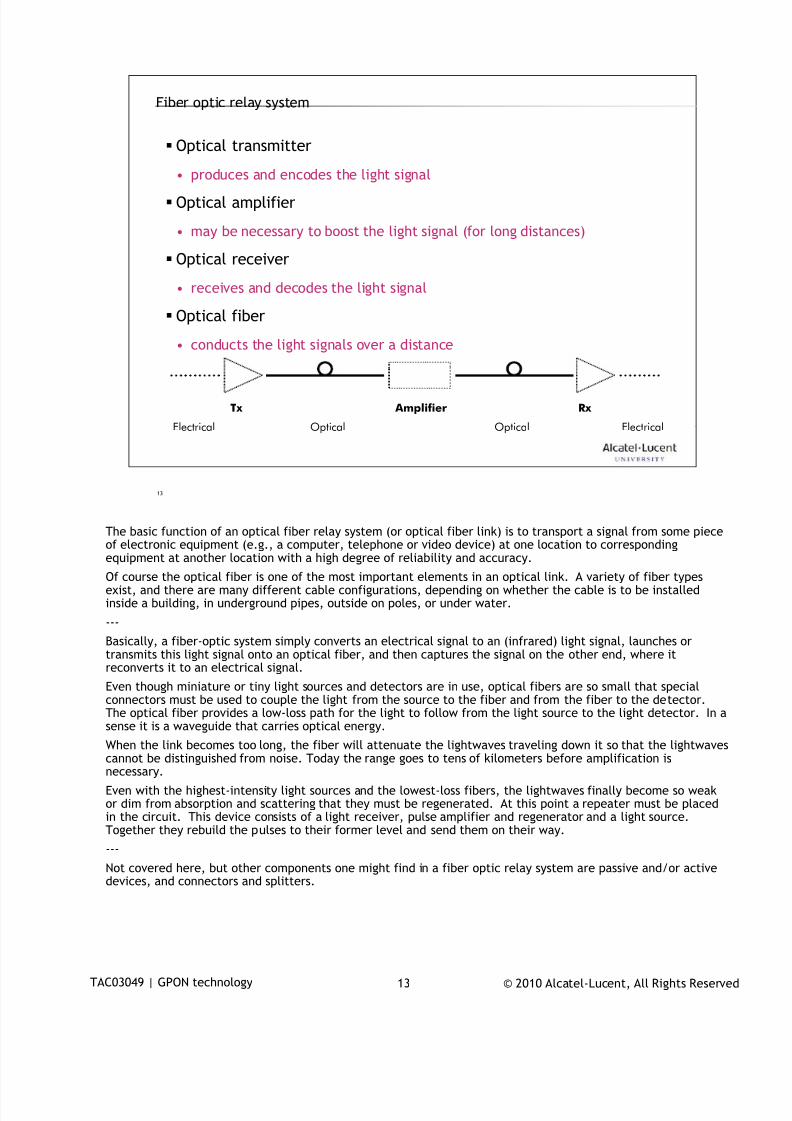
7/18/2019 Alu - A7302 Isam Fttu Operator Gpon Nant-e_ce-PDF
http://slidepdf.com/reader/full/alu-a7302-isam-fttu-operator-gpon-nant-ece-pdf 154/432
© 2010 Alcatel-Lucent, All Rights ReservedTAC03049 | GPON technology 13
13
Fiber optic relay system
Optical transmitter
• produces and encodes the light signal Optical amplifier
• may be necessary to boost the light signal (for long distances)
Optical receiver
• receives and decodes the light signal
Optical fiber
• conducts the light signals over a distance
Tx Rx Amplifier
Electrical ElectricalOptical Optical
The basic function of an optical fiber relay system (or optical fiber link) is to transport a signal from some piece
of electronic equipment (e.g., a computer, telephone or video device) at one location to correspondingequipment at another location with a high degree of reliability and accuracy.
Of course the optical fiber is one of the most important elements in an optical link. A variety of fiber typesexist, and there are many different cable configurations, depending on whether the cable is to be installedinside a building, in underground pipes, outside on poles, or under water.
---
Basically, a fiber-optic system simply converts an electrical signal to an (infrared) light signal, launches ortransmits this light signal onto an optical fiber, and then captures the signal on the other end, where itreconverts it to an electrical signal.
Even though miniature or tiny light sources and detectors are in use, optical fibers are so small that specialconnectors must be used to couple the light from the source to the fiber and from the fiber to the detector.The optical fiber provides a low-loss path for the light to follow from the light source to the light detector. In a
sense it is a waveguide that carries optical energy.When the link becomes too long, the fiber will attenuate the lightwaves traveling down it so that the lightwavescannot be distinguished from noise. Today the range goes to tens of kilometers before amplification isnecessary.
Even with the highest-intensity light sources and the lowest-loss fibers, the lightwaves finally become so weakor dim from absorption and scattering that they must be regenerated. At this point a repeater must be placedin the circuit. This device consists of a light receiver, pulse amplifier and regenerator and a light source.Together they rebuild the pulses to their former level and send them on their way.
---
Not covered here, but other components one might find in a fiber optic relay system are passive and/or activedevices, and connectors and splitters.
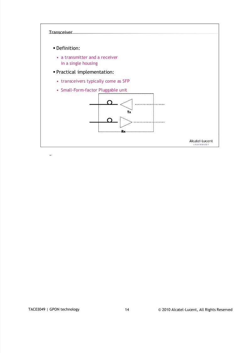
7/18/2019 Alu - A7302 Isam Fttu Operator Gpon Nant-e_ce-PDF
http://slidepdf.com/reader/full/alu-a7302-isam-fttu-operator-gpon-nant-ece-pdf 155/432
© 2010 Alcatel-Lucent, All Rights ReservedTAC03049 | GPON technology 14
14
Transceiver
Definition:
• a transmitter and a receiverin a single housing
Practical implementation:
• transceivers typically come as SFP
• Small-Form-factor Pluggable unit
Rx
Tx
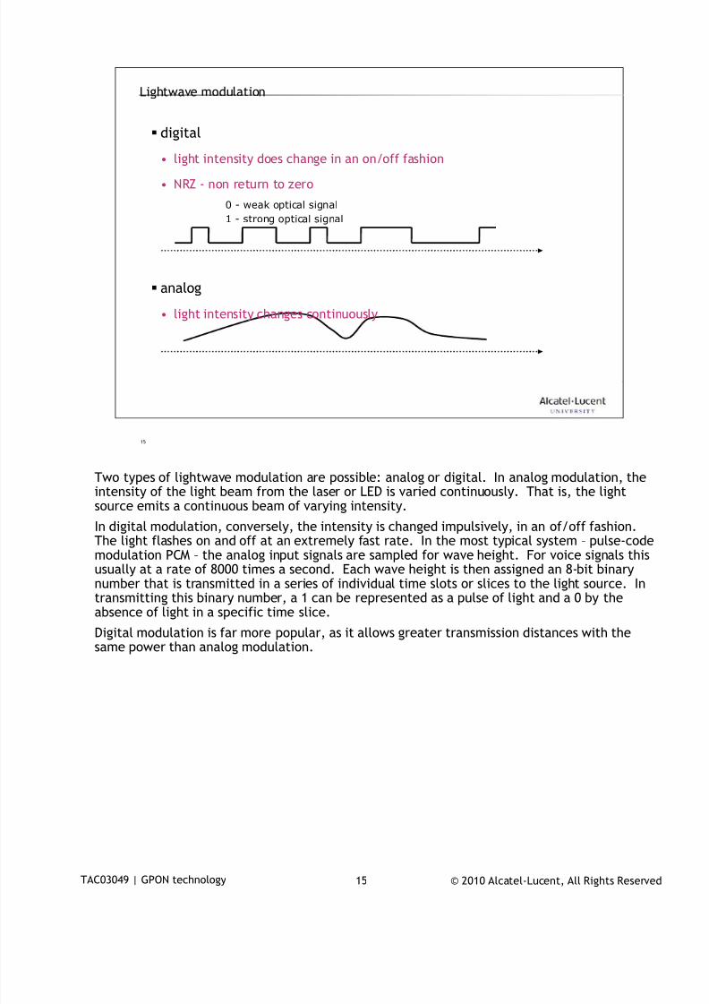
7/18/2019 Alu - A7302 Isam Fttu Operator Gpon Nant-e_ce-PDF
http://slidepdf.com/reader/full/alu-a7302-isam-fttu-operator-gpon-nant-ece-pdf 156/432
© 2010 Alcatel-Lucent, All Rights ReservedTAC03049 | GPON technology 15
15
Lightwave modulation
digital
• light intensity does change in an on/off fashion
• NRZ - non return to zero
0 - weak optical signal
1 - strong optical signal
analog
• light intensity changes continuously
Two types of lightwave modulation are possible: analog or digital. In analog modulation, the
intensity of the light beam from the laser or LED is varied continuously. That is, the lightsource emits a continuous beam of varying intensity.
In digital modulation, conversely, the intensity is changed impulsively, in an of/off fashion.The light flashes on and off at an extremely fast rate. In the most typical system – pulse-codemodulation PCM – the analog input signals are sampled for wave height. For voice signals thisusually at a rate of 8000 times a second. Each wave height is then assigned an 8-bit binarynumber that is transmitted in a series of individual time slots or slices to the light source. Intransmitting this binary number, a 1 can be represented as a pulse of light and a 0 by theabsence of light in a specific time slice.
Digital modulation is far more popular, as it allows greater transmission distances with the
same power than analog modulation.
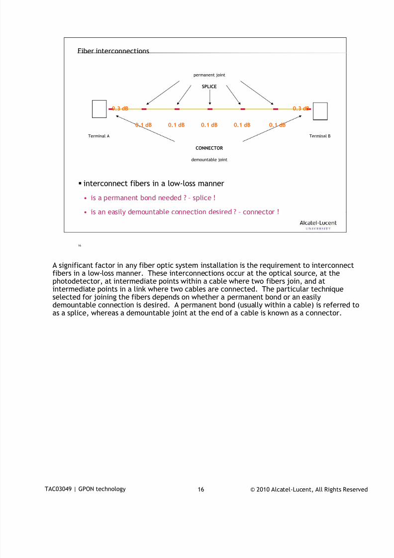
7/18/2019 Alu - A7302 Isam Fttu Operator Gpon Nant-e_ce-PDF
http://slidepdf.com/reader/full/alu-a7302-isam-fttu-operator-gpon-nant-ece-pdf 157/432
© 2010 Alcatel-Lucent, All Rights ReservedTAC03049 | GPON technology 16
16
Fiber interconnections
interconnect fibers in a low-loss manner
• is a permanent bond needed ? – splice !
• is an easily demountable connection desired ? – connector !
Terminal A Terminal B
permanent joint
demountable joint
SPLICE
CONNECTOR
0.3 dB0.3 dB
0.1 dB 0.1 dB 0.1 dB 0.1 dB 0.1 dB
A significant factor in any fiber optic system installation is the requirement to interconnect
fibers in a low-loss manner. These interconnections occur at the optical source, at thephotodetector, at intermediate points within a cable where two fibers join, and atintermediate points in a link where two cables are connected. The particular techniqueselected for joining the fibers depends on whether a permanent bond or an easilydemountable connection is desired. A permanent bond (usually within a cable) is referred toas a splice, whereas a demountable joint at the end of a cable is known as a connector.
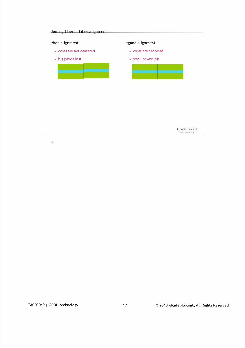
7/18/2019 Alu - A7302 Isam Fttu Operator Gpon Nant-e_ce-PDF
http://slidepdf.com/reader/full/alu-a7302-isam-fttu-operator-gpon-nant-ece-pdf 158/432
© 2010 Alcatel-Lucent, All Rights ReservedTAC03049 | GPON technology 17
17
Joining fibers – Fiber alignment
bad alignment
• cores are not centered
• big power loss
good alignment
• cores are centered
• small power loss
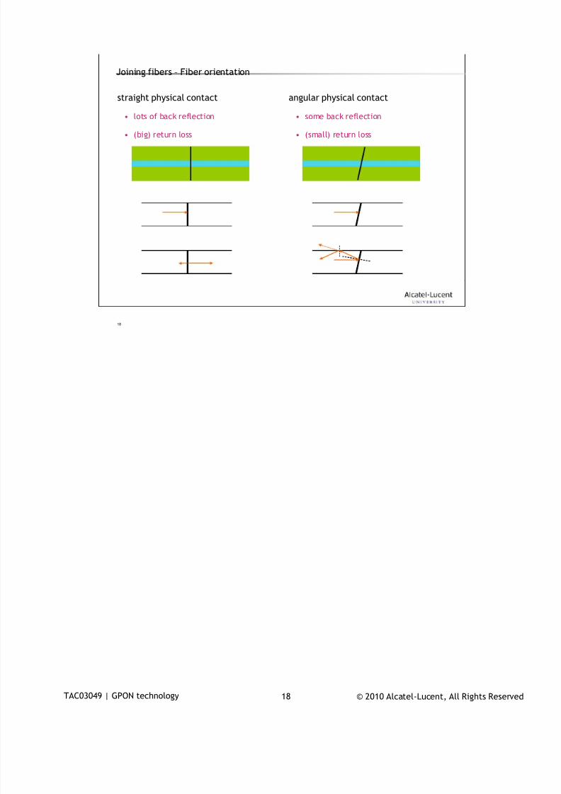
7/18/2019 Alu - A7302 Isam Fttu Operator Gpon Nant-e_ce-PDF
http://slidepdf.com/reader/full/alu-a7302-isam-fttu-operator-gpon-nant-ece-pdf 159/432
© 2010 Alcatel-Lucent, All Rights ReservedTAC03049 | GPON technology 18
18
angular physical contact
• some back reflection
• (small) return loss
straight physical contact
• lots of back reflection
• (big) return loss
Joining fibers – Fiber orientation
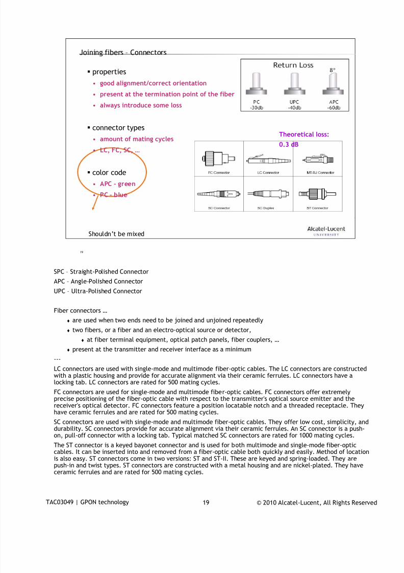
7/18/2019 Alu - A7302 Isam Fttu Operator Gpon Nant-e_ce-PDF
http://slidepdf.com/reader/full/alu-a7302-isam-fttu-operator-gpon-nant-ece-pdf 160/432
© 2010 Alcatel-Lucent, All Rights ReservedTAC03049 | GPON technology 19
19
Joining fibers – Connectors
properties
• good alignment/correct orientation
• present at the termination point of the fiber
• always introduce some loss
connector types
• amount of mating cycles
• LC, FC, SC, …
color code
• APC – green• PC – blue
Theoretical loss:
0.3 dB
Shouldn’t be mixed
SPC – Straight-Polished Connector
APC – Angle-Polished Connector
UPC – Ultra-Polished Connector
Fiber connectors …
are used when two ends need to be joined and unjoined repeatedly
two fibers, or a fiber and an electro-optical source or detector,
at fiber terminal equipment, optical patch panels, fiber couplers, …
present at the transmitter and receiver interface as a minimum
---
LC connectors are used with single-mode and multimode fiber-optic cables. The LC connectors are constructedwith a plastic housing and provide for accurate alignment via their ceramic ferrules. LC connectors have alocking tab. LC connectors are rated for 500 mating cycles.
FC connectors are used for single-mode and multimode fiber-optic cables. FC connectors offer extremelyprecise positioning of the fiber-optic cable with respect to the transmitter's optical source emitter and thereceiver's optical detector. FC connectors feature a position locatable notch and a threaded receptacle. Theyhave ceramic ferrules and are rated for 500 mating cycles.
SC connectors are used with single-mode and multimode fiber-optic cables. They offer low cost, simplicity, anddurability. SC connectors provide for accurate alignment via their ceramic ferrules. An SC connector is a push-on, pull-off connector with a locking tab. Typical matched SC connectors are rated for 1000 mating cycles.
The ST connector is a keyed bayonet connector and is used for both multimode and single-mode fiber-opticcables. It can be inserted into and removed from a fiber-optic cable both quickly and easily. Method of locationis also easy. ST connectors come in two versions: ST and ST-II. These are keyed and spring-loaded. They are
push-in and twist types. ST connectors are constructed with a metal housing and are nickel-plated. They haveceramic ferrules and are rated for 500 mating cycles.
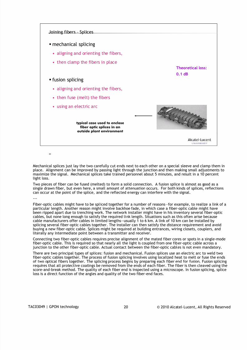
7/18/2019 Alu - A7302 Isam Fttu Operator Gpon Nant-e_ce-PDF
http://slidepdf.com/reader/full/alu-a7302-isam-fttu-operator-gpon-nant-ece-pdf 161/432
© 2010 Alcatel-Lucent, All Rights ReservedTAC03049 | GPON technology 20
20
Joining fibers – Splices
mechanical splicing
• aligning and orienting the fibers,
• then clamp the fibers in place
fusion splicing
• aligning and orienting the fibers,
• then fuse (melt) the fibers
• using an electric arc
typical case used to enclosefiber optic splices in an
outside plant environment
Theoretical loss:
0.1 dB
Mechanical splices just lay the two carefully cut ends next to each other on a special sleeve and clamp them in
place. Alignment can be improved by passing light through the junction and then making small adjustments tomaximize the signal. Mechanical splices take trained personnel about 5 minutes, and result in a 10 percentlight loss.
Two pieces of fiber can be fused (melted) to form a solid connection. A fusion splice is almost as good as asingle drawn fiber, but even here, a small amount of attenuation occurs. For both kinds of splices, reflectionscan occur at the point of the splice, and the reflected energy can interfere with the signal.
---
Fiber-optic cables might have to be spliced together for a number of reasons—for example, to realize a link of aparticular length. Another reason might involve backhoe fade, in which case a fiber-optic cable might havebeen ripped apart due to trenching work. The network installer might have in his inventory several fiber-opticcables, but none long enough to satisfy the required link length. Situations such as this often arise becausecable manufacturers offer cables in limited lengths—usually 1 to 6 km. A link of 10 km can be installed bysplicing several fiber-optic cables together. The installer can then satisfy the distance requirement and avoidbuying a new fiber-optic cable. Splices might be required at building entrances, wiring closets, couplers, andliterally any intermediate point between a transmitter and receiver.
Connecting two fiber-optic cables requires precise alignment of the mated fiber cores or spots in a single-modefiber-optic cable. This is required so that nearly all the light is coupled from one fiber-optic cable across ajunction to the other fiber-optic cable. Actual contact between the fiber-optic cables is not even mandatory.
There are two principal types of splices: fusion and mechanical. Fusion splices use an electric arc to weld twofiber-optic cables together. The process of fusion splicing involves using localized heat to melt or fuse the endsof two optical fibers together. The splicing process begins by preparing each fiber end for fusion. Fusion splicingrequires that all protective coatings be removed from the ends of each fiber. The fiber is then cleaved using thescore-and-break method. The quality of each fiber end is inspected using a microscope. In fusion splicing, spliceloss is a direct function of the angles and quality of the two fiber-end faces.
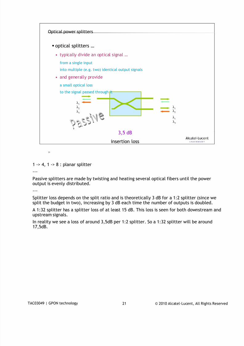
7/18/2019 Alu - A7302 Isam Fttu Operator Gpon Nant-e_ce-PDF
http://slidepdf.com/reader/full/alu-a7302-isam-fttu-operator-gpon-nant-ece-pdf 162/432
© 2010 Alcatel-Lucent, All Rights ReservedTAC03049 | GPON technology 21
21
Optical power splitters
optical splitters …
• typically divide an optical signal …from a single input
into multiple (e.g. two) identical output signals
• and generally provide
a small optical loss
to the signal passed through it
λ 1
λ 1
λ 1
λ 2
λ 2
λ 3
λ 3
3,5 dB
insertion loss
1 -> 4, 1 -> 8 : planar splitter
---
Passive splitters are made by twisting and heating several optical fibers until the poweroutput is evenly distributed.
---
Splitter loss depends on the split ratio and is theoretically 3 dB for a 1:2 splitter (since wesplit the budget in two), increasing by 3 dB each time the number of outputs is doubled.
A 1:32 splitter has a splitter loss of at least 15 dB. This loss is seen for both downstream andupstream signals.
In reality we see a loss of around 3,5dB per 1:2 splitter. So a 1:32 splitter will be around17,5dB.
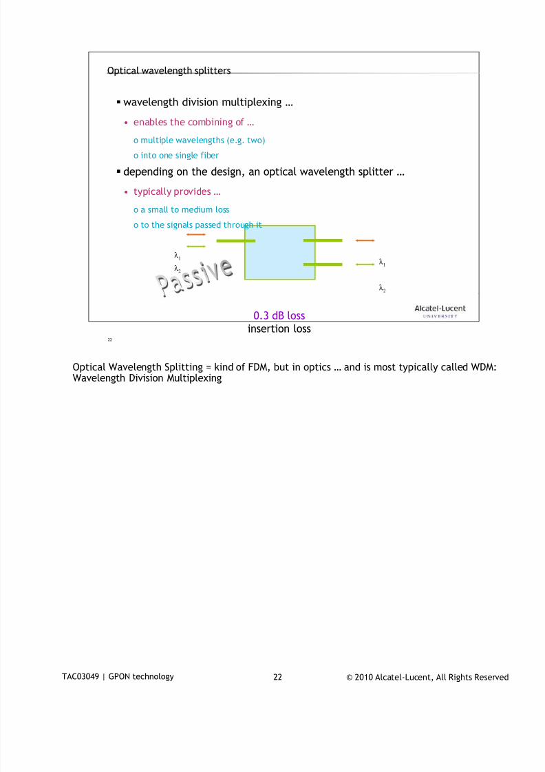
7/18/2019 Alu - A7302 Isam Fttu Operator Gpon Nant-e_ce-PDF
http://slidepdf.com/reader/full/alu-a7302-isam-fttu-operator-gpon-nant-ece-pdf 163/432
© 2010 Alcatel-Lucent, All Rights ReservedTAC03049 | GPON technology 22
22
Optical wavelength splitters
wavelength division multiplexing …
• enables the combining of …o multiple wavelengths (e.g. two)
o into one single fiber
depending on the design, an optical wavelength splitter …
• typically provides …
o a small to medium loss
o to the signals passed through it
0.3 dB loss
λ 1
λ 2λ 1
λ 2
insertion loss
Optical Wavelength Splitting = kind of FDM, but in optics … and is most typically called WDM:
Wavelength Division Multiplexing
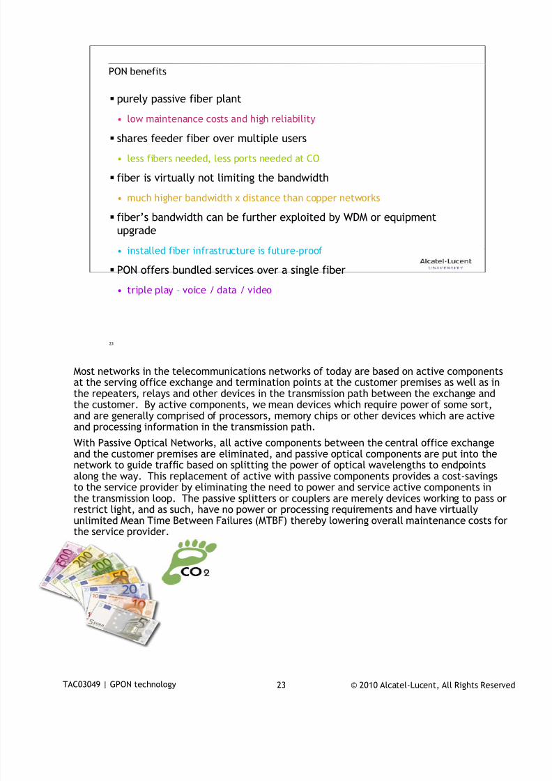
7/18/2019 Alu - A7302 Isam Fttu Operator Gpon Nant-e_ce-PDF
http://slidepdf.com/reader/full/alu-a7302-isam-fttu-operator-gpon-nant-ece-pdf 164/432
© 2010 Alcatel-Lucent, All Rights ReservedTAC03049 | GPON technology 23
23
PON benefits
purely passive fiber plant
• low maintenance costs and high reliability
shares feeder fiber over multiple users
• less fibers needed, less ports needed at CO
fiber is virtually not limiting the bandwidth
• much higher bandwidth x distance than copper networks
fiber’s bandwidth can be further exploited by WDM or equipment
upgrade
• installed fiber infrastructure is future-proof
PON offers bundled services over a single fiber
• triple play – voice / data / video
Most networks in the telecommunications networks of today are based on active components
at the serving office exchange and termination points at the customer premises as well as inthe repeaters, relays and other devices in the transmission path between the exchange andthe customer. By active components, we mean devices which require power of some sort,and are generally comprised of processors, memory chips or other devices which are activeand processing information in the transmission path.
With Passive Optical Networks, all active components between the central office exchangeand the customer premises are eliminated, and passive optical components are put into thenetwork to guide traffic based on splitting the power of optical wavelengths to endpointsalong the way. This replacement of active with passive components provides a cost-savingsto the service provider by eliminating the need to power and service active components inthe transmission loop. The passive splitters or couplers are merely devices working to pass or
restrict light, and as such, have no power or processing requirements and have virtuallyunlimited Mean Time Between Failures (MTBF) thereby lowering overall maintenance costs forthe service provider.
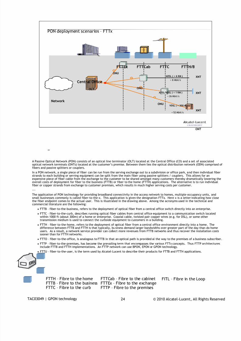
7/18/2019 Alu - A7302 Isam Fttu Operator Gpon Nant-e_ce-PDF
http://slidepdf.com/reader/full/alu-a7302-isam-fttu-operator-gpon-nant-ece-pdf 165/432
© 2010 Alcatel-Lucent, All Rights ReservedTAC03049 | GPON technology 24
24
PON deployment scenarios – FTTx
OLT
Network
ONUADSL ( < 6 KM )
< 8 Mbit/s
FTTEx
ONU
ADSL/VDSL ( < 1 KM )
< 26 Mbit/s
FTTCab
VDSL ( < 300 M )
< 52 Mbit/s
FTTC
ONT
FTTH/B
Central Office
XNT
XNT
XNT
ONU
A Passive Optical Network (PON) consists of an optical line terminator (OLT) located at the Central Office (CO) and a set of associatedoptical network terminals (ONTs) located at the customer’s premise. Between them lies the optical distribution network (ODN) comprised offibers and passive splitters or couplers.
In a PON network, a single piece of fiber can be run from the serving exchange out to a subdivision or office park, and then individual fiberstrands to each building or serving equipment can be split from the main fiber using passive splitters / couplers. This allows for anexpensive piece of fiber cable from the exchange to the customer to be shared amongst many customers thereby dramatically lowering theoverall costs of deployment for fiber to the business (FTTB) or fiber to the home (FTTH) applications. The alternative is to run individualfiber or copper strands from exchange to customer premises, which results in much higher serving costs per customer.
---
The application of PON technology for providing broadband connectivity in the access network to homes, multiple-occupancy units, andsmall businesses commonly is called fiber-to-the-x. This application is given the designation FTTx. Here x is a letter indicating how closethe fiber endpoint comes to the actual user. This is illustrated in the drawing above. Among the acronyms used in the technical andcommercial literature are the following:
FTTB – fiber-to-the-business, refers to the deployment of optical fiber from a central office switch directly into an enterprise.
FTTC – fiber-to-the-curb, describes running optical fiber cables from central office equipment to a communication switch locatedwithin 1000 ft (about 300m) of a home or enterprise. Coaxial cable, twisted pair copper wires (e.g. for DSL), or some othertransmission medium is used to connect the curbside equipment to customers in a building.
FTTH – fiber-to-the-home, refers to the deployment of optical fiber from a central office environment directly into a home. Thedifference between FTTB and FTTH is that typically, business demand larger bandwidths over greater part of the day than do homeusers. As a result, a network service provider can collect more revenues from FTTB networks and thus recover the installation costssooner than for FTTH networks.
FTTO – fiber-to-the-office, is analogous to FTTB in that an optical path is provided al the way to the premises of a business subscriber.
FTTP – fiber-to-the-premises, has become the prevailing term that encompasses the various FTTx concepts. Thus FTTP architecturesinclude FTTB and FTTH implementations. An FTTP network can use BPON, EPON or GPON technology.
FTTU – fiber-to-the-user, is the term used by Alcatel-Lucent to describe their products for FTTB and FTTH applications.
FTTCab – Fibre to the cabinetFTTEx – Fibre to the exchangeFTTP – Fibre to the premises
FTTH – Fibre to the homeFTTB – Fibre to the businessFTTC – Fibre to the curb
FITL – Fibre in the Loop

7/18/2019 Alu - A7302 Isam Fttu Operator Gpon Nant-e_ce-PDF
http://slidepdf.com/reader/full/alu-a7302-isam-fttu-operator-gpon-nant-ece-pdf 166/432
© 2010 Alcatel-Lucent, All Rights ReservedTAC03049 | GPON technology 25
25
PON standardization2
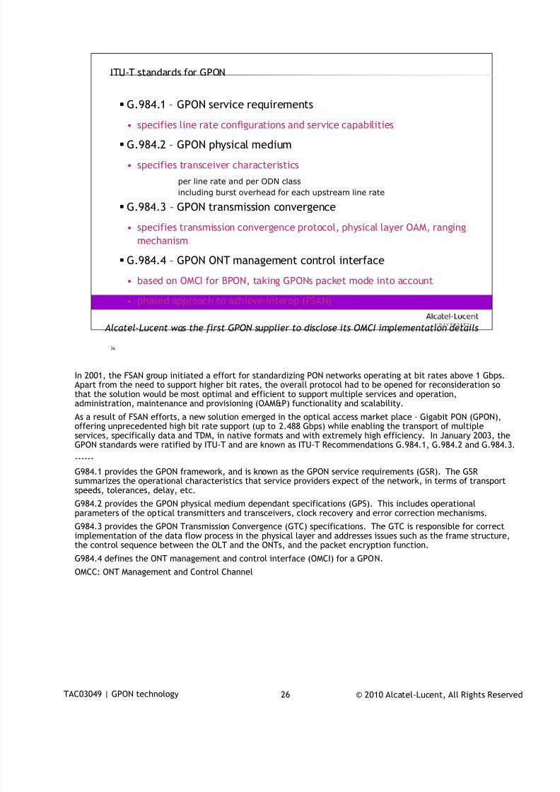
7/18/2019 Alu - A7302 Isam Fttu Operator Gpon Nant-e_ce-PDF
http://slidepdf.com/reader/full/alu-a7302-isam-fttu-operator-gpon-nant-ece-pdf 167/432
© 2010 Alcatel-Lucent, All Rights ReservedTAC03049 | GPON technology 26
26
ITU-T standards for GPON
G.984.1 – GPON service requirements
• specifies line rate configurations and service capabilities
G.984.2 – GPON physical medium
• specifies transceiver characteristics
per line rate and per ODN class
including burst overhead for each upstream line rate
G.984.3 – GPON transmission convergence
• specifies transmission convergence protocol, physical layer OAM, ranging
mechanism
G.984.4 – GPON ONT management control interface
• based on OMCI for BPON, taking GPONs packet mode into account
• phased approach to achieve interop (FSAN)
Alcatel-Lucent was the first GPON supplier to disclose its OMCI implementation details
In 2001, the FSAN group initiated a effort for standardizing PON networks operating at bit rates above 1 Gbps.
Apart from the need to support higher bit rates, the overall protocol had to be opened for reconsideration sothat the solution would be most optimal and efficient to support multiple services and operation,administration, maintenance and provisioning (OAM&P) functionality and scalability.
As a result of FSAN efforts, a new solution emerged in the optical access market place – Gigabit PON (GPON),offering unprecedented high bit rate support (up to 2.488 Gbps) while enabling the transport of multipleservices, specifically data and TDM, in native formats and with extremely high efficiency. In January 2003, theGPON standards were ratified by ITU-T and are known as ITU-T Recommendations G.984.1, G.984.2 and G.984.3.
------
G984.1 provides the GPON framework, and is known as the GPON service requirements (GSR). The GSRsummarizes the operational characteristics that service providers expect of the network, in terms of transportspeeds, tolerances, delay, etc.
G984.2 provides the GPON physical medium dependant specifications (GPS). This includes operational
parameters of the optical transmitters and transceivers, clock recovery and error correction mechanisms.G984.3 provides the GPON Transmission Convergence (GTC) specifications. The GTC is responsible for correctimplementation of the data flow process in the physical layer and addresses issues such as the frame structure,the control sequence between the OLT and the ONTs, and the packet encryption function.
G984.4 defines the ONT management and control interface (OMCI) for a GPON.
OMCC: ONT Management and Control Channel
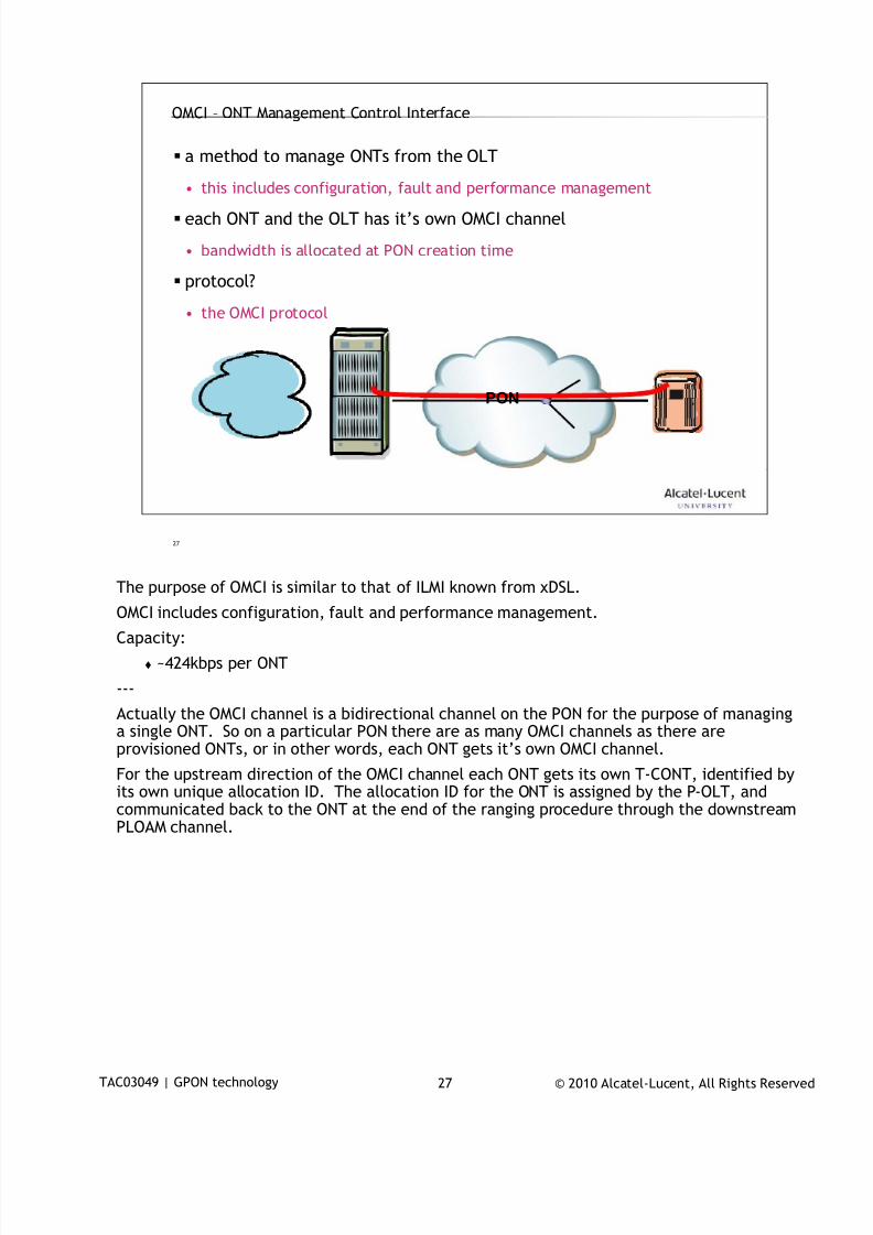
7/18/2019 Alu - A7302 Isam Fttu Operator Gpon Nant-e_ce-PDF
http://slidepdf.com/reader/full/alu-a7302-isam-fttu-operator-gpon-nant-ece-pdf 168/432
© 2010 Alcatel-Lucent, All Rights ReservedTAC03049 | GPON technology 27
27
PON
OMCI – ONT Management Control Interface
a method to manage ONTs from the OLT
• this includes configuration, fault and performance management
each ONT and the OLT has it’s own OMCI channel
• bandwidth is allocated at PON creation time
protocol?
• the OMCI protocol
The purpose of OMCI is similar to that of ILMI known from xDSL.
OMCI includes configuration, fault and performance management.
Capacity:
~424kbps per ONT
---
Actually the OMCI channel is a bidirectional channel on the PON for the purpose of managinga single ONT. So on a particular PON there are as many OMCI channels as there areprovisioned ONTs, or in other words, each ONT gets it’s own OMCI channel.
For the upstream direction of the OMCI channel each ONT gets its own T-CONT, identified byits own unique allocation ID. The allocation ID for the ONT is assigned by the P-OLT, andcommunicated back to the ONT at the end of the ranging procedure through the downstreamPLOAM channel.
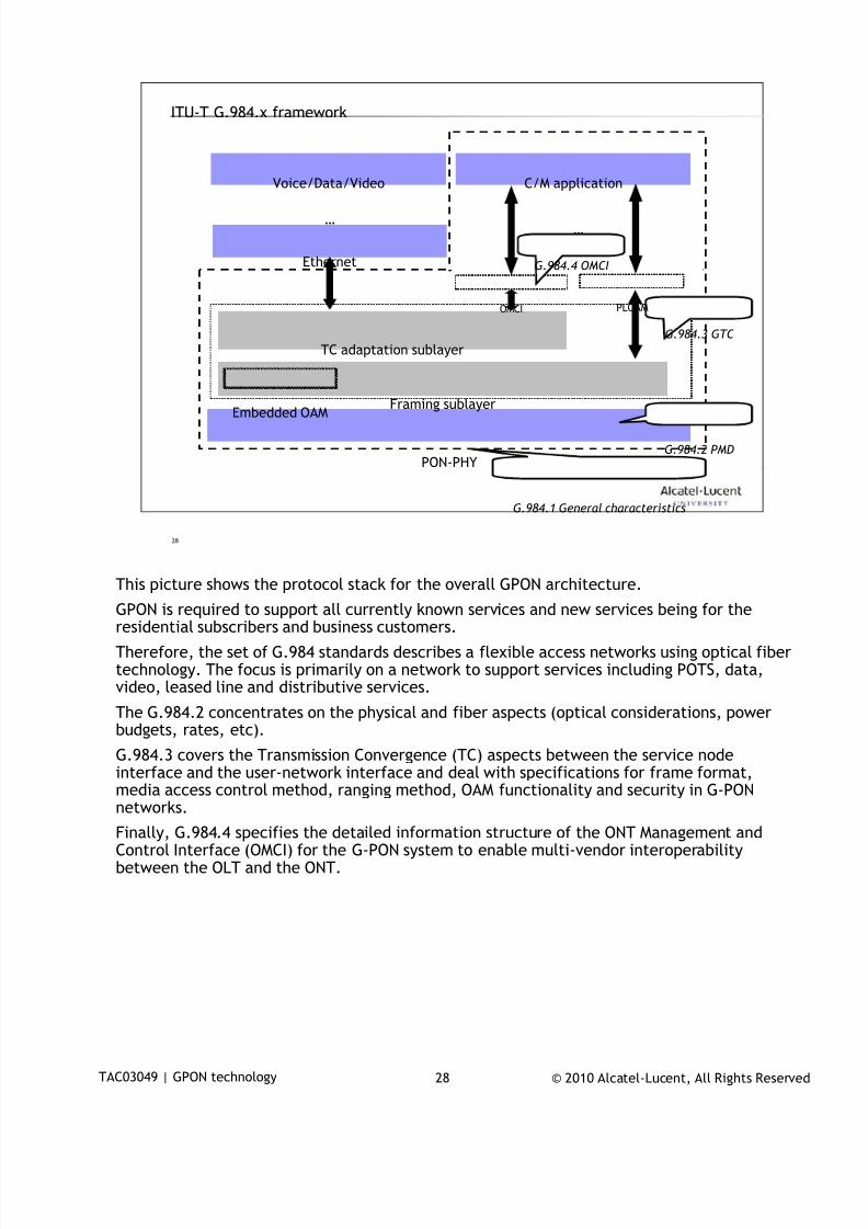
7/18/2019 Alu - A7302 Isam Fttu Operator Gpon Nant-e_ce-PDF
http://slidepdf.com/reader/full/alu-a7302-isam-fttu-operator-gpon-nant-ece-pdf 169/432
© 2010 Alcatel-Lucent, All Rights ReservedTAC03049 | GPON technology 28
28
ITU-T G.984.x framework
Ethernet
TC adaptation sublayer
Framing sublayer
PON-PHY
C/M application
PLOAMOMCI
Voice/Data/Video
Embedded OAM
……
G.984.3 GTC
G.984.2 PMD
G.984.1 General characteristics
G.984.4 OMCI
This picture shows the protocol stack for the overall GPON architecture.
GPON is required to support all currently known services and new services being for theresidential subscribers and business customers.
Therefore, the set of G.984 standards describes a flexible access networks using optical fibertechnology. The focus is primarily on a network to support services including POTS, data,video, leased line and distributive services.
The G.984.2 concentrates on the physical and fiber aspects (optical considerations, powerbudgets, rates, etc).
G.984.3 covers the Transmission Convergence (TC) aspects between the service nodeinterface and the user-network interface and deal with specifications for frame format,media access control method, ranging method, OAM functionality and security in G-PONnetworks.
Finally, G.984.4 specifies the detailed information structure of the ONT Management andControl Interface (OMCI) for the G-PON system to enable multi-vendor interoperabilitybetween the OLT and the ONT.

7/18/2019 Alu - A7302 Isam Fttu Operator Gpon Nant-e_ce-PDF
http://slidepdf.com/reader/full/alu-a7302-isam-fttu-operator-gpon-nant-ece-pdf 170/432
© 2010 Alcatel-Lucent, All Rights ReservedTAC03049 | GPON technology 29
29
GPON fundamentals3
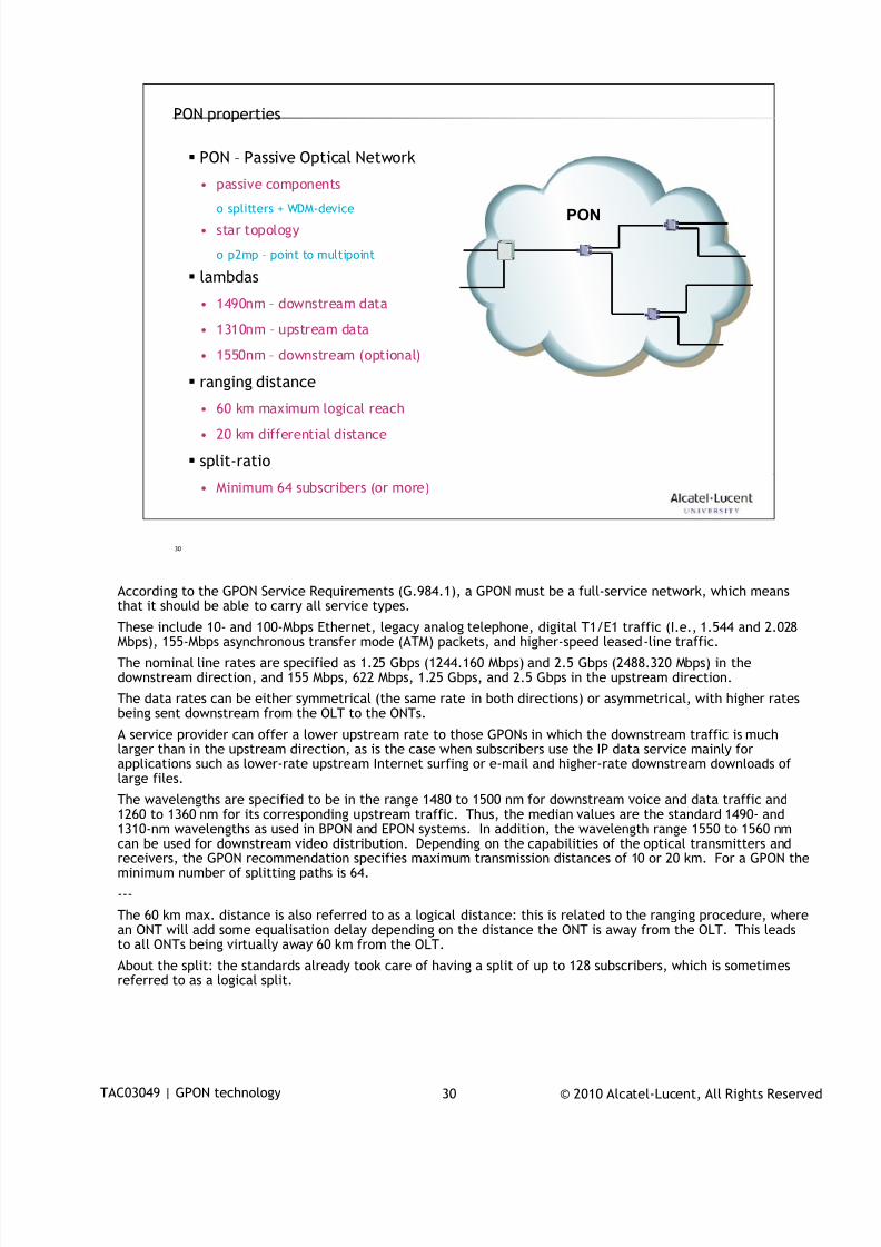
7/18/2019 Alu - A7302 Isam Fttu Operator Gpon Nant-e_ce-PDF
http://slidepdf.com/reader/full/alu-a7302-isam-fttu-operator-gpon-nant-ece-pdf 171/432
© 2010 Alcatel-Lucent, All Rights ReservedTAC03049 | GPON technology 30
30
PON properties
PON – Passive Optical Network
• passive components
o splitters + WDM-device
• star topology
o p2mp – point to multipoint
lambdas
• 1490nm – downstream data
• 1310nm – upstream data
• 1550nm – downstream (optional)
ranging distance
• 60 km maximum logical reach
• 20 km differential distance
split-ratio
• Minimum 64 subscribers (or more)
PON
According to the GPON Service Requirements (G.984.1), a GPON must be a full-service network, which means
that it should be able to carry all service types.These include 10- and 100-Mbps Ethernet, legacy analog telephone, digital T1/E1 traffic (I.e., 1.544 and 2.028Mbps), 155-Mbps asynchronous transfer mode (ATM) packets, and higher-speed leased-line traffic.
The nominal line rates are specified as 1.25 Gbps (1244.160 Mbps) and 2.5 Gbps (2488.320 Mbps) in thedownstream direction, and 155 Mbps, 622 Mbps, 1.25 Gbps, and 2.5 Gbps in the upstream direction.
The data rates can be either symmetrical (the same rate in both directions) or asymmetrical, with higher ratesbeing sent downstream from the OLT to the ONTs.
A service provider can offer a lower upstream rate to those GPONs in which the downstream traffic is muchlarger than in the upstream direction, as is the case when subscribers use the IP data service mainly forapplications such as lower-rate upstream Internet surfing or e-mail and higher-rate downstream downloads oflarge files.
The wavelengths are specified to be in the range 1480 to 1500 nm for downstream voice and data traffic and
1260 to 1360 nm for its corresponding upstream traffic. Thus, the median values are the standard 1490- and1310-nm wavelengths as used in BPON and EPON systems. In addition, the wavelength range 1550 to 1560 nmcan be used for downstream video distribution. Depending on the capabilities of the optical transmitters andreceivers, the GPON recommendation specifies maximum transmission distances of 10 or 20 km. For a GPON theminimum number of splitting paths is 64.
---
The 60 km max. distance is also referred to as a logical distance: this is related to the ranging procedure, wherean ONT will add some equalisation delay depending on the distance the ONT is away from the OLT. This leadsto all ONTs being virtually away 60 km from the OLT.
About the split: the standards already took care of having a split of up to 128 subscribers, which is sometimesreferred to as a logical split.
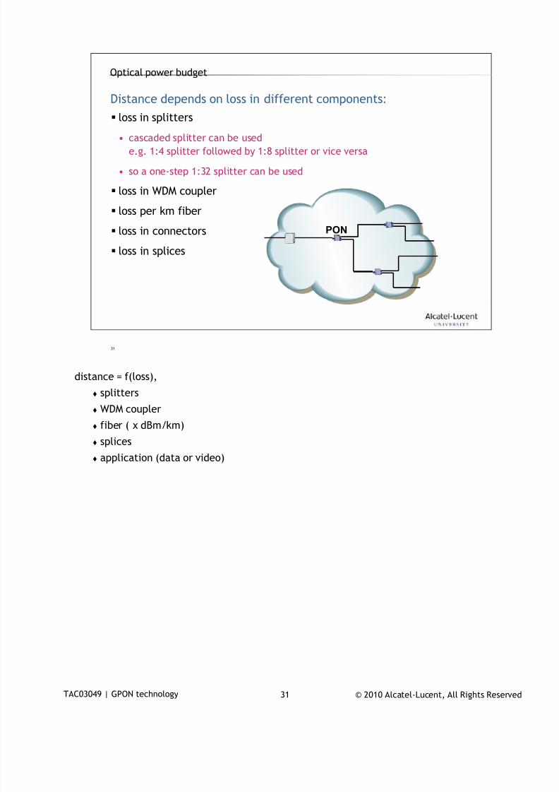
7/18/2019 Alu - A7302 Isam Fttu Operator Gpon Nant-e_ce-PDF
http://slidepdf.com/reader/full/alu-a7302-isam-fttu-operator-gpon-nant-ece-pdf 172/432
© 2010 Alcatel-Lucent, All Rights ReservedTAC03049 | GPON technology 31
31
Optical power budget
loss in splitters
• cascaded splitter can be used
e.g. 1:4 splitter followed by 1:8 splitter or vice versa
• so a one-step 1:32 splitter can be used
loss in WDM coupler
loss per km fiber
loss in connectors
loss in splices
PON
Distance depends on loss in different components:
distance = f(loss),
splitters
WDM coupler
fiber ( x dBm/km)
splices
application (data or video)
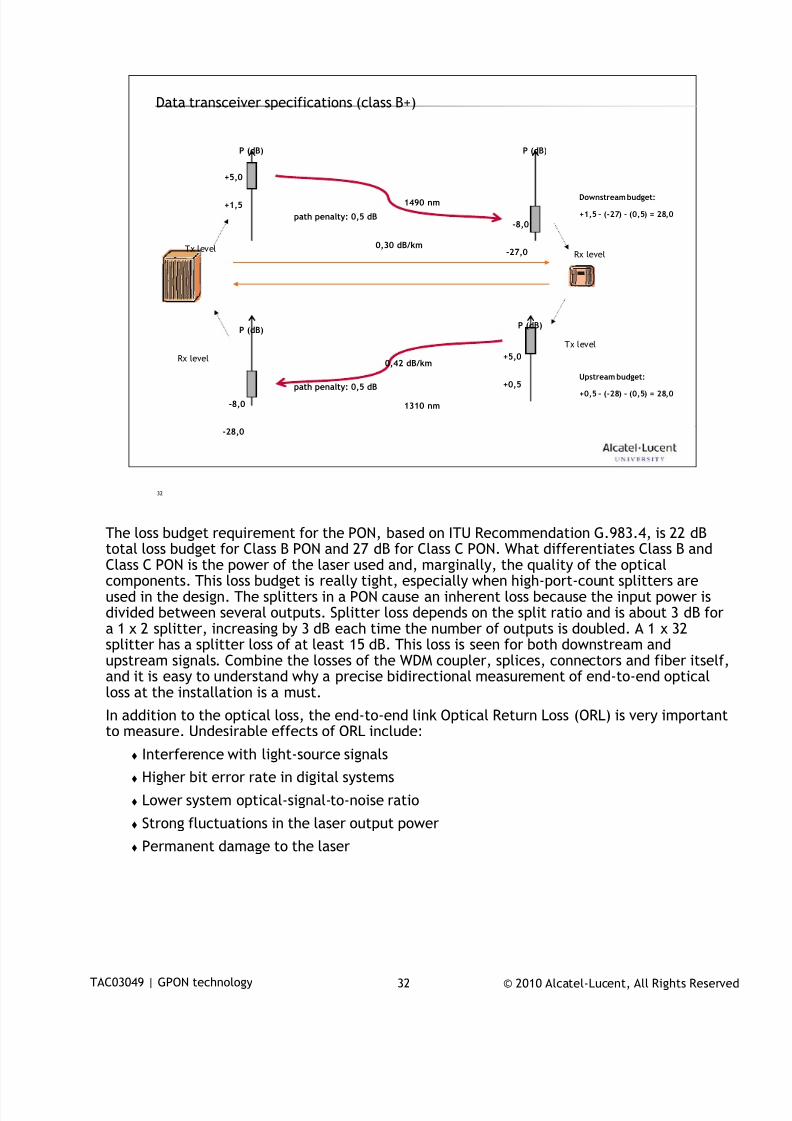
7/18/2019 Alu - A7302 Isam Fttu Operator Gpon Nant-e_ce-PDF
http://slidepdf.com/reader/full/alu-a7302-isam-fttu-operator-gpon-nant-ece-pdf 173/432
© 2010 Alcatel-Lucent, All Rights ReservedTAC03049 | GPON technology 32
32
Data transceiver specifications (class B+)
+5,0
P (dB)
+1,5
+5,0
P (dB)
+0,5
-8,0
P (dB)
-27,0
-8,0
P (dB)
-28,0
1490 nm
1310 nm
path penalty: 0,5 dB
path penalty: 0,5 dB
Downstream budget:
+1,5 – (-27) – (0,5) = 28,0
Upstream budget:
+0,5 – (-28) – (0,5) = 28,0
Tx level
Tx level
Rx level
Rx level
0,30 dB/km
0,42 dB/km
The loss budget requirement for the PON, based on ITU Recommendation G.983.4, is 22 dB
total loss budget for Class B PON and 27 dB for Class C PON. What differentiates Class B andClass C PON is the power of the laser used and, marginally, the quality of the opticalcomponents. This loss budget is really tight, especially when high-port-count splitters areused in the design. The splitters in a PON cause an inherent loss because the input power isdivided between several outputs. Splitter loss depends on the split ratio and is about 3 dB fora 1 x 2 splitter, increasing by 3 dB each time the number of outputs is doubled. A 1 x 32splitter has a splitter loss of at least 15 dB. This loss is seen for both downstream andupstream signals. Combine the losses of the WDM coupler, splices, connectors and fiber itself,and it is easy to understand why a precise bidirectional measurement of end-to-end opticalloss at the installation is a must.
In addition to the optical loss, the end-to-end link Optical Return Loss (ORL) is very important
to measure. Undesirable effects of ORL include:
Interference with light-source signals
Higher bit error rate in digital systems
Lower system optical-signal-to-noise ratio
Strong fluctuations in the laser output power
Permanent damage to the laser
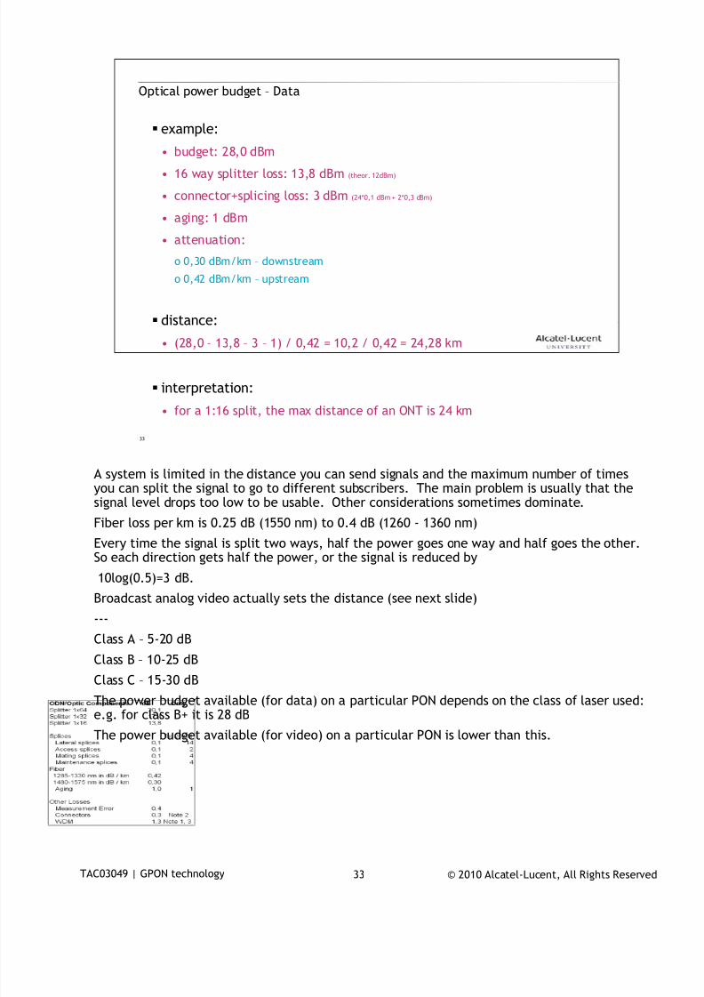
7/18/2019 Alu - A7302 Isam Fttu Operator Gpon Nant-e_ce-PDF
http://slidepdf.com/reader/full/alu-a7302-isam-fttu-operator-gpon-nant-ece-pdf 174/432
© 2010 Alcatel-Lucent, All Rights ReservedTAC03049 | GPON technology 33
33
Optical power budget – Data
example:
• budget: 28,0 dBm
• 16 way splitter loss: 13,8 dBm (theor. 12dBm)
• connector+splicing loss: 3 dBm (24*0,1 dBm + 2*0,3 dBm)
• aging: 1 dBm
• attenuation:
o 0,30 dBm/km – downstream
o 0,42 dBm/km – upstream
distance:• (28,0 – 13,8 – 3 – 1) / 0,42 = 10,2 / 0,42 = 24,28 km
interpretation:
• for a 1:16 split, the max distance of an ONT is 24 km
A system is limited in the distance you can send signals and the maximum number of times
you can split the signal to go to different subscribers. The main problem is usually that thesignal level drops too low to be usable. Other considerations sometimes dominate.
Fiber loss per km is 0.25 dB (1550 nm) to 0.4 dB (1260 - 1360 nm)
Every time the signal is split two ways, half the power goes one way and half goes the other.So each direction gets half the power, or the signal is reduced by
10log(0.5)=3 dB.
Broadcast analog video actually sets the distance (see next slide)
---
Class A – 5-20 dB
Class B – 10-25 dB
Class C – 15-30 dB
The power budget available (for data) on a particular PON depends on the class of laser used:e.g. for class B+ it is 28 dB
The power budget available (for video) on a particular PON is lower than this.
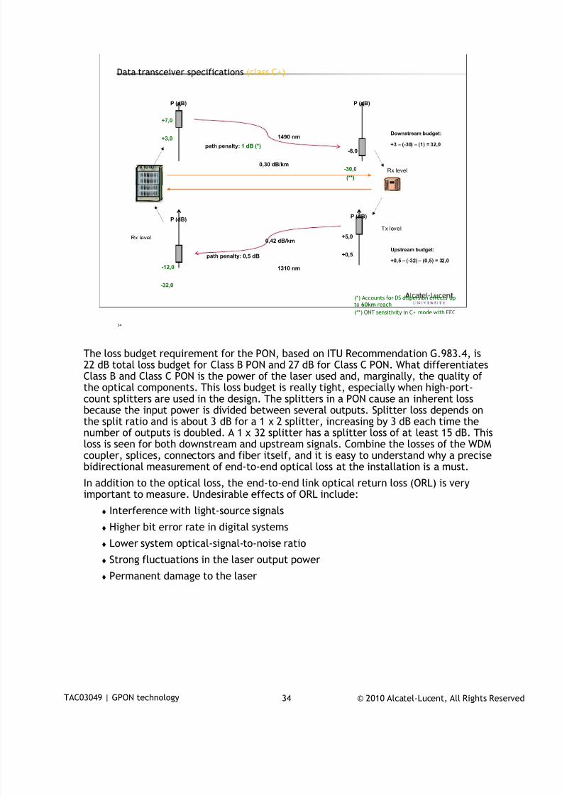
7/18/2019 Alu - A7302 Isam Fttu Operator Gpon Nant-e_ce-PDF
http://slidepdf.com/reader/full/alu-a7302-isam-fttu-operator-gpon-nant-ece-pdf 175/432
© 2010 Alcatel-Lucent, All Rights ReservedTAC03049 | GPON technology 34
34
Data transceiver specifications (class C+)
+7,0
P (dB)
+3,0
+5,0
P (dB)
+0,5
-8,0
P (dB)
-30,0
(**)
-12,0
P (dB)
-32,0
1490 nm
1310 nm
path penalty: 1 dB (*)
path penalty: 0,5 dB
Downstream budget:
+3 – (-30) – (1) = 32,0
Upstream budget:
+0,5 – (-32) – (0,5) = 32,0
Tx level
Tx level
Rx level
Rx level
0,30 dB/km
0,42 dB/km
(*) Accounts for DS dispersion effects upto 60km reach
(**) ONT sensitivity in C+ mode with FEC
The loss budget requirement for the PON, based on ITU Recommendation G.983.4, is22 dB total loss budget for Class B PON and 27 dB for Class C PON. What differentiatesClass B and Class C PON is the power of the laser used and, marginally, the quality of
the optical components. This loss budget is really tight, especially when high-port-count splitters are used in the design. The splitters in a PON cause an inherent lossbecause the input power is divided between several outputs. Splitter loss depends onthe split ratio and is about 3 dB for a 1 x 2 splitter, increasing by 3 dB each time thenumber of outputs is doubled. A 1 x 32 splitter has a splitter loss of at least 15 dB. Thisloss is seen for both downstream and upstream signals. Combine the losses of the WDMcoupler, splices, connectors and fiber itself, and it is easy to understand why a precisebidirectional measurement of end-to-end optical loss at the installation is a must.
In addition to the optical loss, the end-to-end link optical return loss (ORL) is veryimportant to measure. Undesirable effects of ORL include:
Interference with light-source signals
Higher bit error rate in digital systems
Lower system optical-signal-to-noise ratio
Strong fluctuations in the laser output power
Permanent damage to the laser
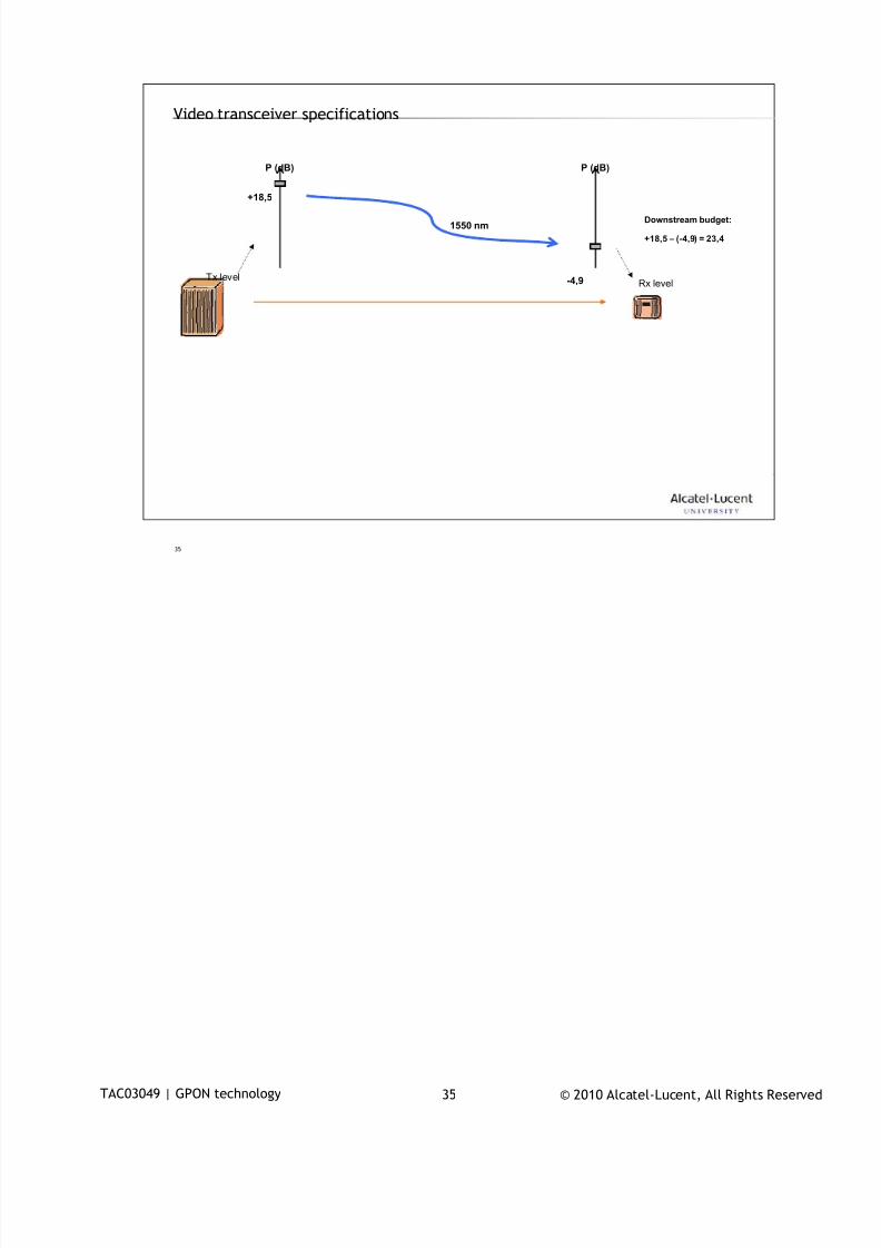
7/18/2019 Alu - A7302 Isam Fttu Operator Gpon Nant-e_ce-PDF
http://slidepdf.com/reader/full/alu-a7302-isam-fttu-operator-gpon-nant-ece-pdf 176/432
© 2010 Alcatel-Lucent, All Rights ReservedTAC03049 | GPON technology 35
35
Video transceiver specifications
+18,5
P (dB) P (dB)
-4,9
1550 nmDownstream budget:
+18,5 – (-4,9) = 23,4
Tx levelRx level
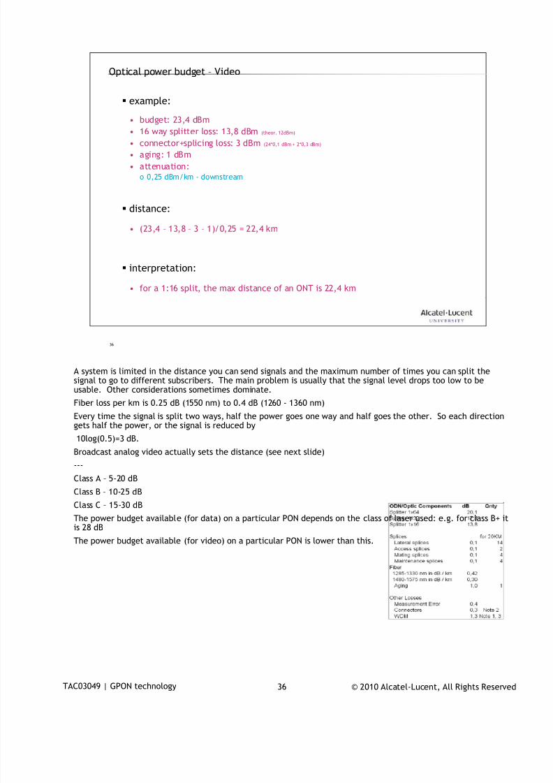
7/18/2019 Alu - A7302 Isam Fttu Operator Gpon Nant-e_ce-PDF
http://slidepdf.com/reader/full/alu-a7302-isam-fttu-operator-gpon-nant-ece-pdf 177/432
© 2010 Alcatel-Lucent, All Rights ReservedTAC03049 | GPON technology 36
36
Optical power budget – Video
example:
• budget: 23,4 dBm
• 16 way splitter loss: 13,8 dBm (theor. 12dBm)
• connector+splicing loss: 3 dBm (24*0,1 dBm + 2*0,3 dBm)
• aging: 1 dBm
• attenuation:o 0,25 dBm/km - downstream
distance:
• (23,4 – 13,8 – 3 – 1)/0,25 = 22,4 km
interpretation:
• for a 1:16 split, the max distance of an ONT is 22,4 km
A system is limited in the distance you can send signals and the maximum number of times you can split the
signal to go to different subscribers. The main problem is usually that the signal level drops too low to beusable. Other considerations sometimes dominate.
Fiber loss per km is 0.25 dB (1550 nm) to 0.4 dB (1260 - 1360 nm)
Every time the signal is split two ways, half the power goes one way and half goes the other. So each directiongets half the power, or the signal is reduced by
10log(0.5)=3 dB.
Broadcast analog video actually sets the distance (see next slide)
---
Class A – 5-20 dB
Class B – 10-25 dB
Class C – 15-30 dBThe power budget available (for data) on a particular PON depends on the class of laser used: e.g. for class B+ itis 28 dB
The power budget available (for video) on a particular PON is lower than this.
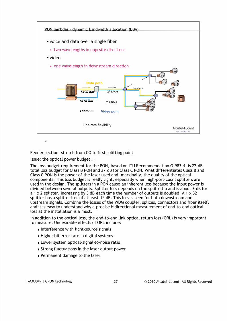
7/18/2019 Alu - A7302 Isam Fttu Operator Gpon Nant-e_ce-PDF
http://slidepdf.com/reader/full/alu-a7302-isam-fttu-operator-gpon-nant-ece-pdf 178/432
© 2010 Alcatel-Lucent, All Rights ReservedTAC03049 | GPON technology 37
37
PON lambdas – dynamic bandwidth allocation (DBA)
voice and data over a single fiber
• two wavelengths in opposite directions
video
• one wavelength in downstream direction
Splitters
1490 nm
1310 nm
Data path
1550 nm Video path
Line rate flexibility
X Mb/s
Y Mb/s
Feeder section: stretch from CO to first splitting point
Issue: the optical power budget …
The loss budget requirement for the PON, based on ITU Recommendation G.983.4, is 22 dBtotal loss budget for Class B PON and 27 dB for Class C PON. What differentiates Class B andClass C PON is the power of the laser used and, marginally, the quality of the opticalcomponents. This loss budget is really tight, especially when high-port-count splitters areused in the design. The splitters in a PON cause an inherent loss because the input power isdivided between several outputs. Splitter loss depends on the split ratio and is about 3 dB fora 1 x 2 splitter, increasing by 3 dB each time the number of outputs is doubled. A 1 x 32splitter has a splitter loss of at least 15 dB. This loss is seen for both downstream andupstream signals. Combine the losses of the WDM coupler, splices, connectors and fiber itself,
and it is easy to understand why a precise bidirectional measurement of end-to-end opticalloss at the installation is a must.
In addition to the optical loss, the end-to-end link optical return loss (ORL) is very importantto measure. Undesirable effects of ORL include:
Interference with light-source signals
Higher bit error rate in digital systems
Lower system optical-signal-to-noise ratio
Strong fluctuations in the laser output power
Permanent damage to the laser
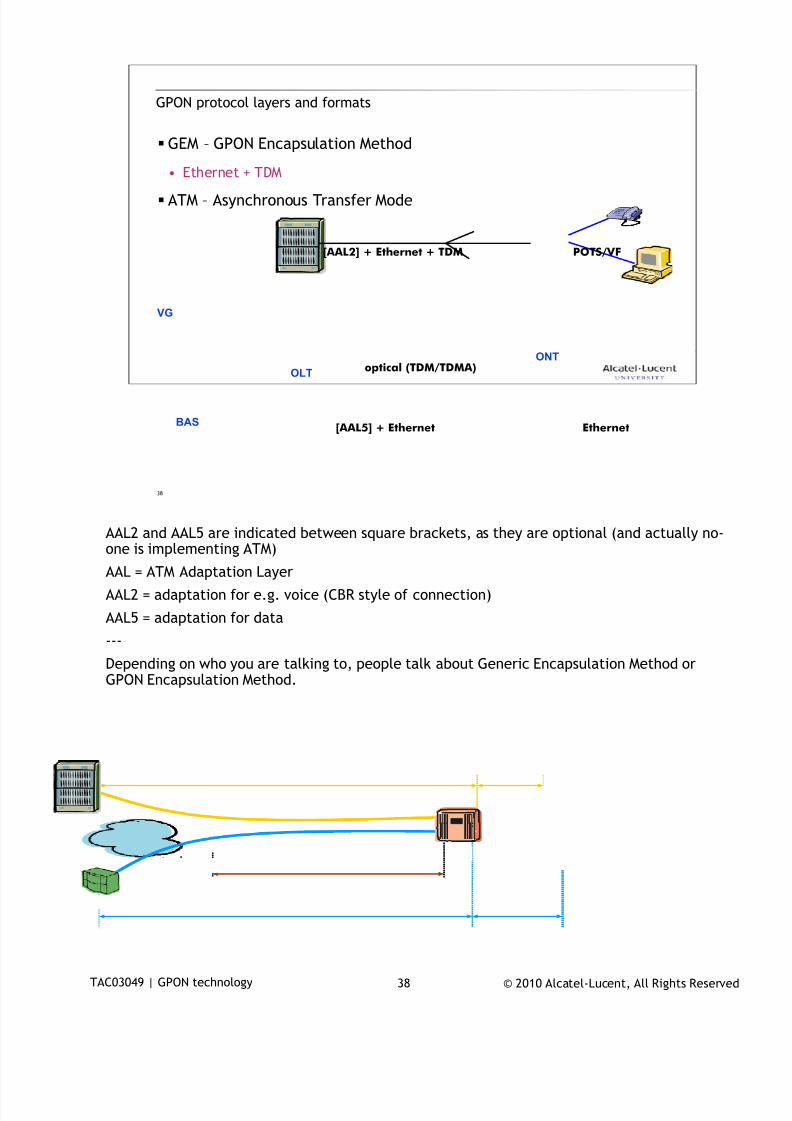
7/18/2019 Alu - A7302 Isam Fttu Operator Gpon Nant-e_ce-PDF
http://slidepdf.com/reader/full/alu-a7302-isam-fttu-operator-gpon-nant-ece-pdf 179/432
© 2010 Alcatel-Lucent, All Rights ReservedTAC03049 | GPON technology 38
38
GPON protocol layers and formats
GEM – GPON Encapsulation Method
• Ethernet + TDM
ATM – Asynchronous Transfer Mode
VG
optical (TDM/TDMA)
Ethernet[AAL5] + Ethernet
[AAL2] + Ethernet + TDM POTS/VF
OLT
ONT
BAS
AAL2 and AAL5 are indicated between square brackets, as they are optional (and actually no-
one is implementing ATM)
AAL = ATM Adaptation Layer
AAL2 = adaptation for e.g. voice (CBR style of connection)
AAL5 = adaptation for data
---
Depending on who you are talking to, people talk about Generic Encapsulation Method orGPON Encapsulation Method.
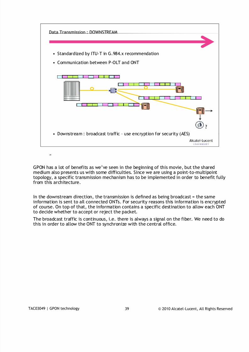
7/18/2019 Alu - A7302 Isam Fttu Operator Gpon Nant-e_ce-PDF
http://slidepdf.com/reader/full/alu-a7302-isam-fttu-operator-gpon-nant-ece-pdf 180/432
© 2010 Alcatel-Lucent, All Rights ReservedTAC03049 | GPON technology 39
39
Data Transmission : DOWNSTREAM
• Standardized by ITU-T in G.984.x recommendation
• Communication between P-OLT and ONT
• Downstream : broadcast traffic – use encryption for security (AES)
?
GPON has a lot of benefits as we’ve seen in the beginning of this movie, but the shared
medium also presents us with some difficulties. Since we are using a point-to-multipointtopology, a specific transmission mechanism has to be implemented in order to benefit fullyfrom this architecture.
In the downstream direction, the transmission is defined as being broadcast = the sameinformation is sent to all connected ONTs. For security reasons this information is encryptedof course. On top of that, the information contains a specific destination to allow each ONTto decide whether to accept or reject the packet.
The broadcast traffic is continuous, i.e. there is always a signal on the fiber. We need to dothis in order to allow the ONT to synchronize with the central office.
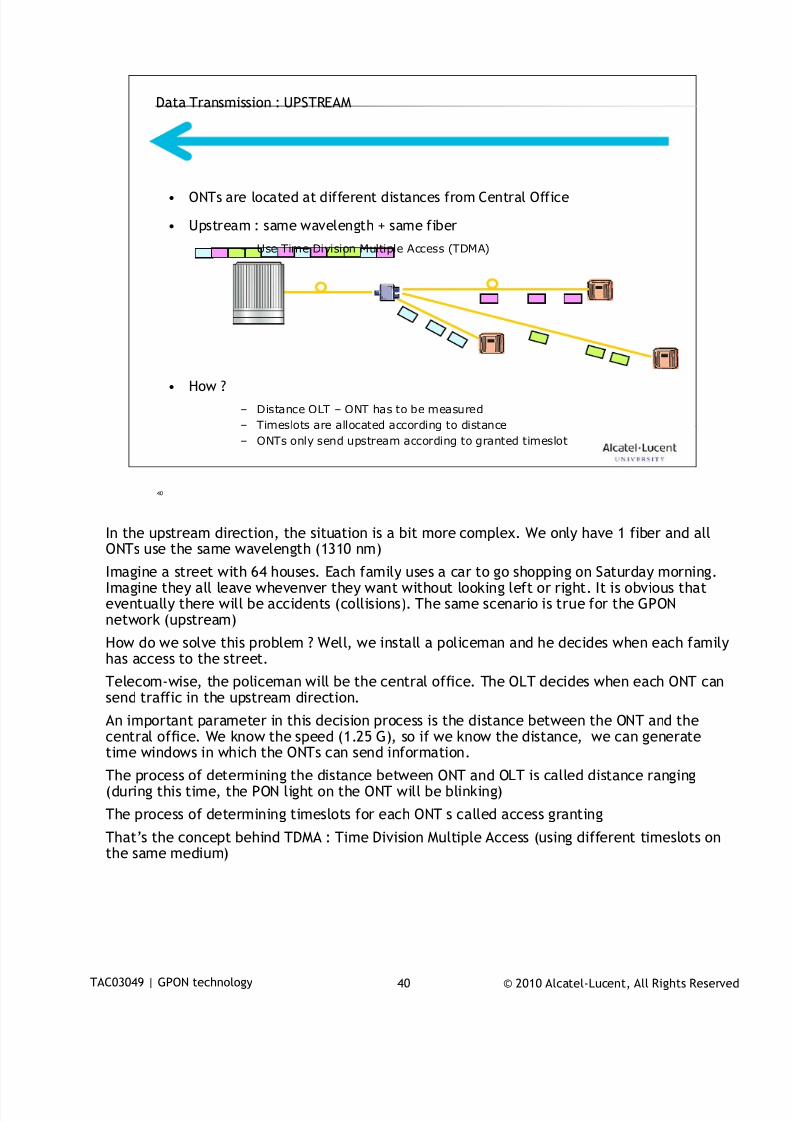
7/18/2019 Alu - A7302 Isam Fttu Operator Gpon Nant-e_ce-PDF
http://slidepdf.com/reader/full/alu-a7302-isam-fttu-operator-gpon-nant-ece-pdf 181/432
© 2010 Alcatel-Lucent, All Rights ReservedTAC03049 | GPON technology 40
40
Data Transmission : UPSTREAM
• ONTs are located at different distances from Central Office
• Upstream : same wavelength + same fiber
– Use Time Division Multiple Access (TDMA)
• How ?
– Distance OLT – ONT has to be measured
– Timeslots are allocated according to distance
– ONTs only send upstream according to granted timeslot
In the upstream direction, the situation is a bit more complex. We only have 1 fiber and all
ONTs use the same wavelength (1310 nm)
Imagine a street with 64 houses. Each family uses a car to go shopping on Saturday morning.Imagine they all leave whevenver they want without looking left or right. It is obvious thateventually there will be accidents (collisions). The same scenario is true for the GPONnetwork (upstream)
How do we solve this problem ? Well, we install a policeman and he decides when each familyhas access to the street.
Telecom-wise, the policeman will be the central office. The OLT decides when each ONT cansend traffic in the upstream direction.
An important parameter in this decision process is the distance between the ONT and thecentral office. We know the speed (1.25 G), so if we know the distance, we can generatetime windows in which the ONTs can send information.
The process of determining the distance between ONT and OLT is called distance ranging(during this time, the PON light on the ONT will be blinking)
The process of determining timeslots for each ONT s called access granting
That’s the concept behind TDMA : Time Division Multiple Access (using different timeslots onthe same medium)
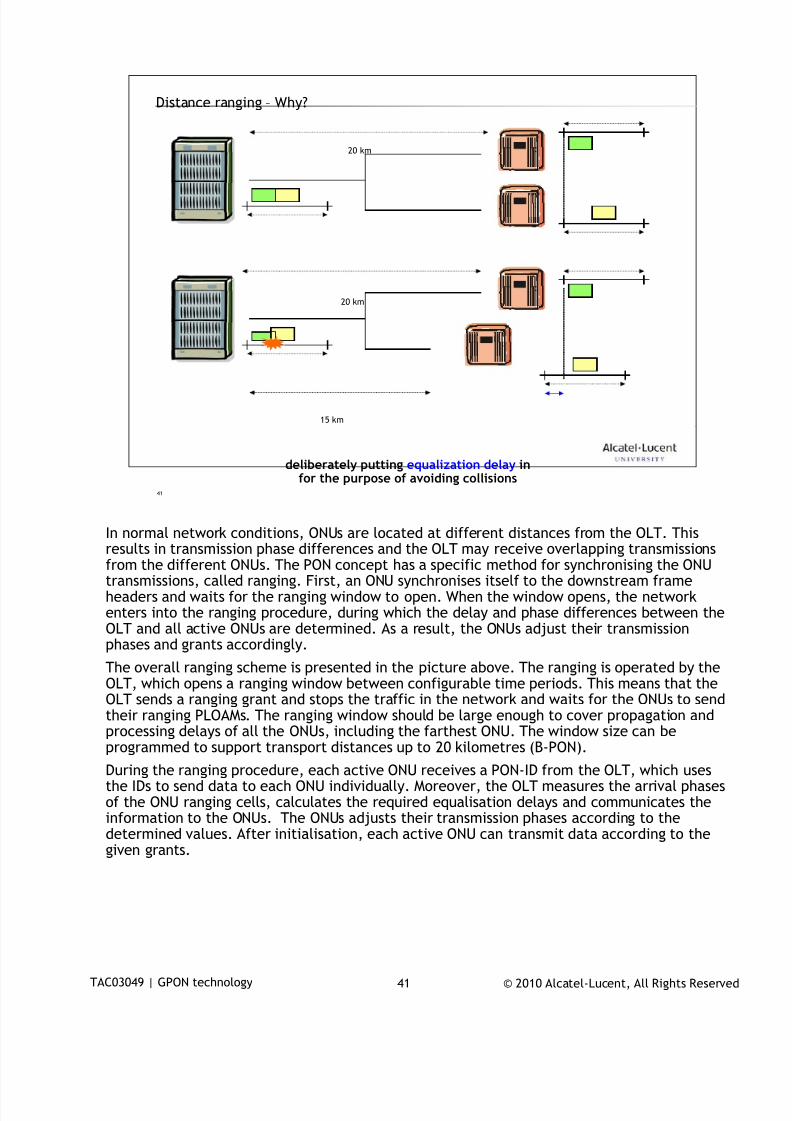
7/18/2019 Alu - A7302 Isam Fttu Operator Gpon Nant-e_ce-PDF
http://slidepdf.com/reader/full/alu-a7302-isam-fttu-operator-gpon-nant-ece-pdf 182/432
© 2010 Alcatel-Lucent, All Rights ReservedTAC03049 | GPON technology 41
41
Distance ranging – Why?
deliberately putting equalization delay infor the purpose of avoiding collisions
20 km
20 km
15 km
In normal network conditions, ONUs are located at different distances from the OLT. This
results in transmission phase differences and the OLT may receive overlapping transmissionsfrom the different ONUs. The PON concept has a specific method for synchronising the ONUtransmissions, called ranging. First, an ONU synchronises itself to the downstream frameheaders and waits for the ranging window to open. When the window opens, the networkenters into the ranging procedure, during which the delay and phase differences between theOLT and all active ONUs are determined. As a result, the ONUs adjust their transmissionphases and grants accordingly.
The overall ranging scheme is presented in the picture above. The ranging is operated by theOLT, which opens a ranging window between configurable time periods. This means that theOLT sends a ranging grant and stops the traffic in the network and waits for the ONUs to sendtheir ranging PLOAMs. The ranging window should be large enough to cover propagation and
processing delays of all the ONUs, including the farthest ONU. The window size can beprogrammed to support transport distances up to 20 kilometres (B-PON).
During the ranging procedure, each active ONU receives a PON-ID from the OLT, which usesthe IDs to send data to each ONU individually. Moreover, the OLT measures the arrival phasesof the ONU ranging cells, calculates the required equalisation delays and communicates theinformation to the ONUs. The ONUs adjusts their transmission phases according to thedetermined values. After initialisation, each active ONU can transmit data according to thegiven grants.
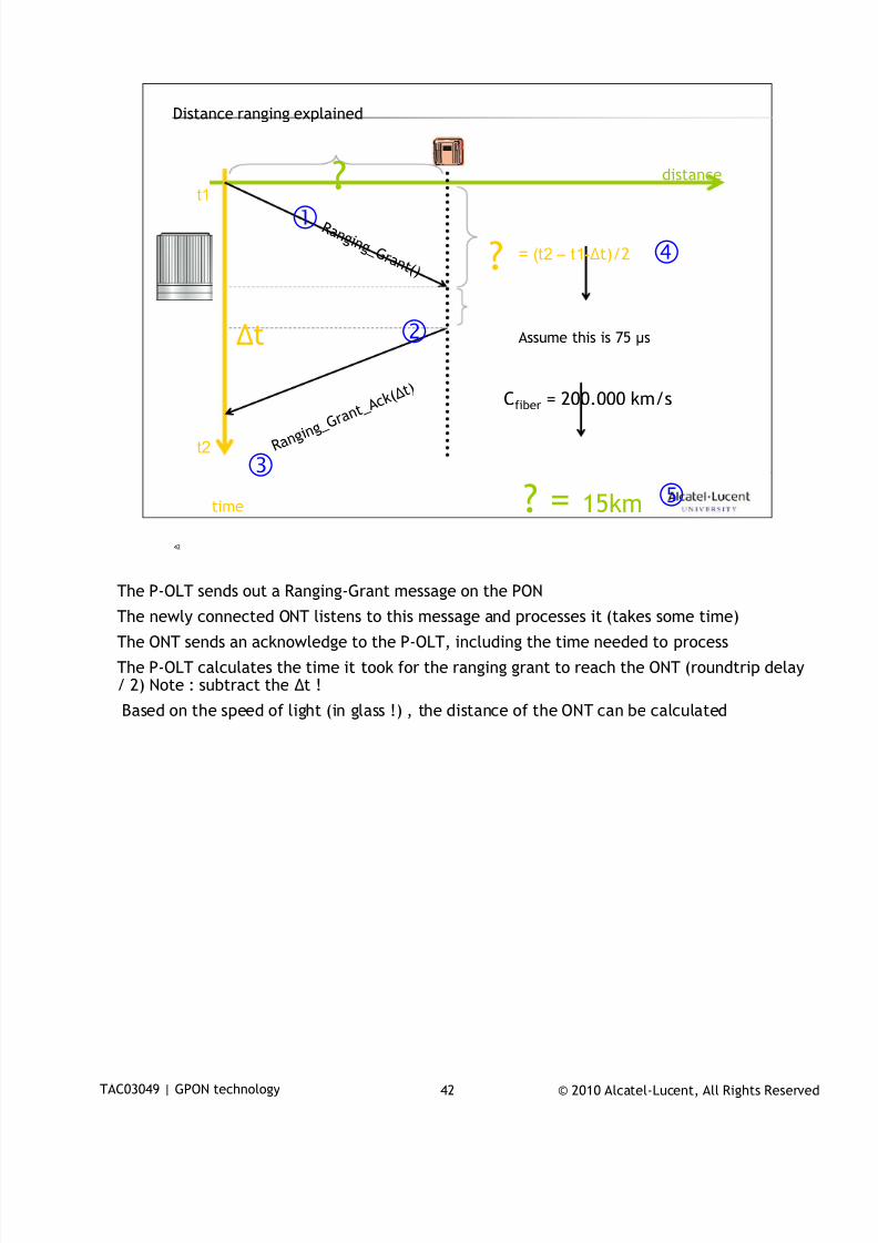
7/18/2019 Alu - A7302 Isam Fttu Operator Gpon Nant-e_ce-PDF
http://slidepdf.com/reader/full/alu-a7302-isam-fttu-operator-gpon-nant-ece-pdf 183/432
© 2010 Alcatel-Lucent, All Rights ReservedTAC03049 | GPON technology 42
42
Distance ranging explained
time
distance
R a n g i n g _G r a n t ( )
t1
t2
?
Δt
R a n g i n
g _ G r a n t_ A c k
( Δ t )
= (t2 – t1-Δt)/2
Assume this is 75 μs
Cfiber = 200.000 km/s
?
? = 15km
The P-OLT sends out a Ranging-Grant message on the PON
The newly connected ONT listens to this message and processes it (takes some time)
The ONT sends an acknowledge to the P-OLT, including the time needed to process
The P-OLT calculates the time it took for the ranging grant to reach the ONT (roundtrip delay/ 2) Note : subtract the Δt !
Based on the speed of light (in glass !) , the distance of the ONT can be calculated
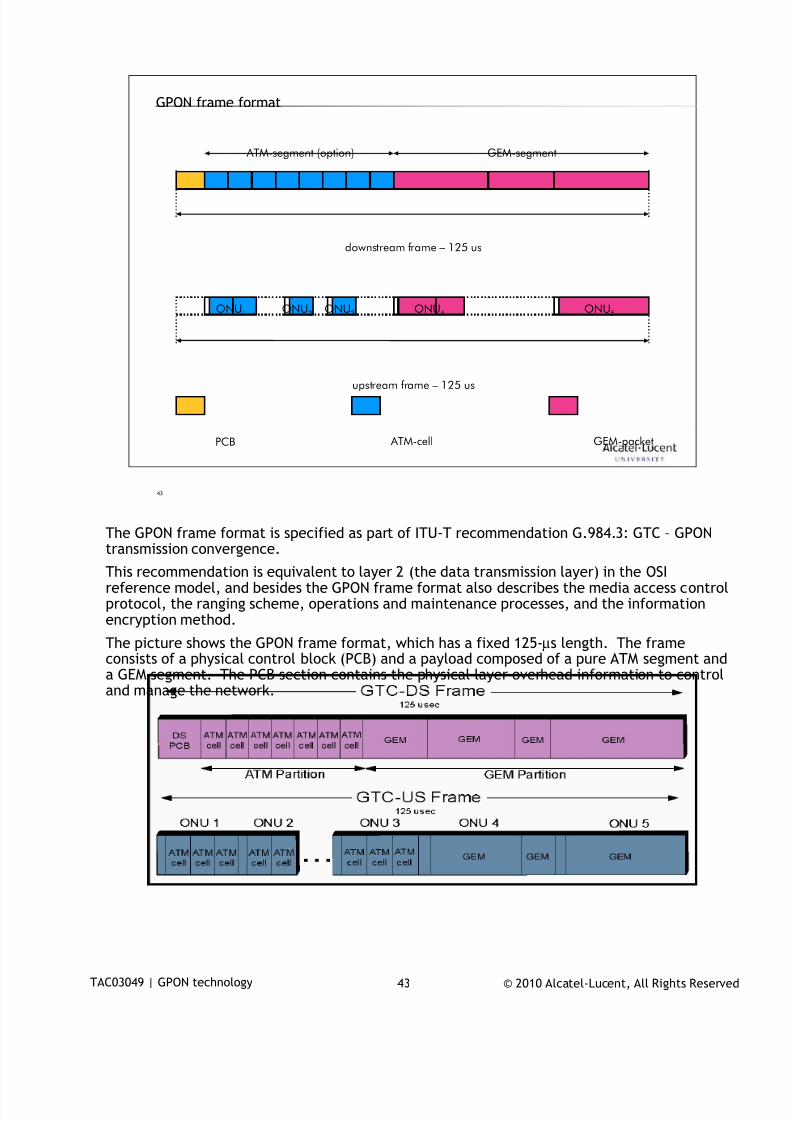
7/18/2019 Alu - A7302 Isam Fttu Operator Gpon Nant-e_ce-PDF
http://slidepdf.com/reader/full/alu-a7302-isam-fttu-operator-gpon-nant-ece-pdf 184/432
© 2010 Alcatel-Lucent, All Rights ReservedTAC03049 | GPON technology 43
43
GPON frame format
ATM-segment (option)
downstream frame – 125 us
GEM-segment
upstream frame – 125 us
ONU1 ONU2 ONU3 ONU4 ONU5
PCB GEM-packet ATM-cell
The GPON frame format is specified as part of ITU-T recommendation G.984.3: GTC – GPON
transmission convergence.
This recommendation is equivalent to layer 2 (the data transmission layer) in the OSIreference model, and besides the GPON frame format also describes the media access controlprotocol, the ranging scheme, operations and maintenance processes, and the informationencryption method.
The picture shows the GPON frame format, which has a fixed 125-µs length. The frameconsists of a physical control block (PCB) and a payload composed of a pure ATM segment anda GEM segment. The PCB section contains the physical layer overhead information to controland manage the network.
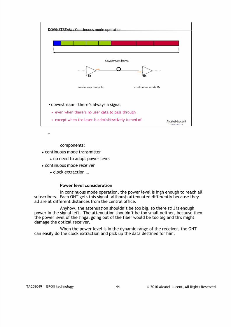
7/18/2019 Alu - A7302 Isam Fttu Operator Gpon Nant-e_ce-PDF
http://slidepdf.com/reader/full/alu-a7302-isam-fttu-operator-gpon-nant-ece-pdf 185/432
© 2010 Alcatel-Lucent, All Rights ReservedTAC03049 | GPON technology 44
44
DOWNSTREAM : Continuous mode operation
downstream – there’s always a signal• even when there’s no user data to pass through
• except when the laser is administratively turned of
downstream frame
Tx Rx
continuous mode Tx continuous mode Rx
components:
continuous mode transmitter
no need to adapt power level continuous mode receiver
clock extraction …
Power level consideration
In continuous mode operation, the power level is high enough to reach allsubscribers. Each ONT gets this signal, although attenuated differently because theyall are at different distances from the central office.
Anyhow, the attenuation shouldn’t be too big, so there still is enough
power in the signal left. The attenuation shouldn’t be too small neither, because thenthe power level of the singal going out of the fiber would be too big and this mightdamage the optical receiver.
When the power level is in the dynamic range of the receiver, the ONTcan easily do the clock extraction and pick up the data destined for him.
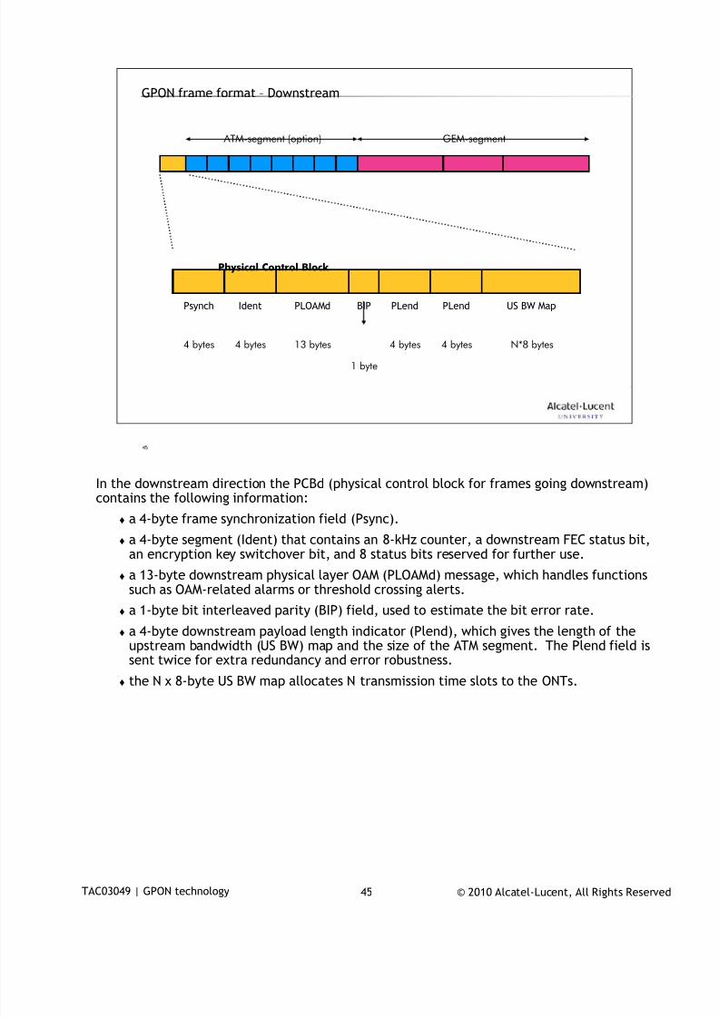
7/18/2019 Alu - A7302 Isam Fttu Operator Gpon Nant-e_ce-PDF
http://slidepdf.com/reader/full/alu-a7302-isam-fttu-operator-gpon-nant-ece-pdf 186/432
© 2010 Alcatel-Lucent, All Rights ReservedTAC03049 | GPON technology 45
45
GPON frame format – Downstream
ATM-segment (option) GEM-segment
Psynch Ident PLOAMd BIP PLend PLend US BW Map
Physical Control Block
4 bytes 4 bytes 13 bytes 4 bytes 4 bytes N*8 bytes
1 byte
In the downstream direction the PCBd (physical control block for frames going downstream)
contains the following information:
a 4-byte frame synchronization field (Psync).
a 4-byte segment (Ident) that contains an 8-kHz counter, a downstream FEC status bit,an encryption key switchover bit, and 8 status bits reserved for further use.
a 13-byte downstream physical layer OAM (PLOAMd) message, which handles functionssuch as OAM-related alarms or threshold crossing alerts.
a 1-byte bit interleaved parity (BIP) field, used to estimate the bit error rate.
a 4-byte downstream payload length indicator (Plend), which gives the length of theupstream bandwidth (US BW) map and the size of the ATM segment. The Plend field is
sent twice for extra redundancy and error robustness. the N x 8-byte US BW map allocates N transmission time slots to the ONTs.
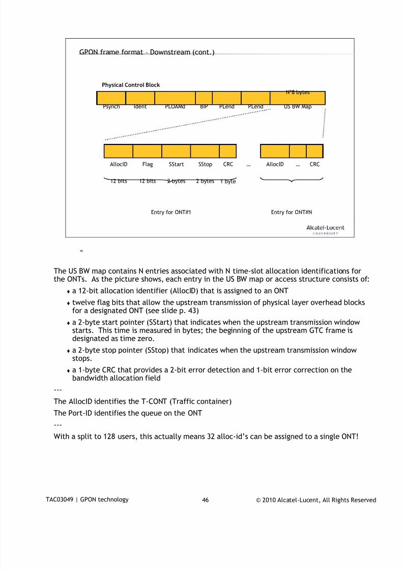
7/18/2019 Alu - A7302 Isam Fttu Operator Gpon Nant-e_ce-PDF
http://slidepdf.com/reader/full/alu-a7302-isam-fttu-operator-gpon-nant-ece-pdf 187/432
© 2010 Alcatel-Lucent, All Rights ReservedTAC03049 | GPON technology 46
46
GPON frame format – Downstream (cont.)
Psynch Ident PLOAMd BIP PLend PLend US BW Map
Physical Control Block
N*8 bytes
… AllocID … CRCAllocID Flag SStart SStop CRC
12 bits 12 bits 2 bytes 2 bytes 1 byte
Entry for ONT#1 Entry for ONT#N
The US BW map contains N entries associated with N time-slot allocation identifications for
the ONTs. As the picture shows, each entry in the US BW map or access structure consists of:
a 12-bit allocation identifier (AllocID) that is assigned to an ONT
twelve flag bits that allow the upstream transmission of physical layer overhead blocksfor a designated ONT (see slide p. 43)
a 2-byte start pointer (SStart) that indicates when the upstream transmission windowstarts. This time is measured in bytes; the beginning of the upstream GTC frame isdesignated as time zero.
a 2-byte stop pointer (SStop) that indicates when the upstream transmission windowstops.
a 1-byte CRC that provides a 2-bit error detection and 1-bit error correction on thebandwidth allocation field
---
The AllocID identifies the T-CONT (Traffic container)
The Port-ID identifies the queue on the ONT
---
With a split to 128 users, this actually means 32 alloc-id’s can be assigned to a single ONT!
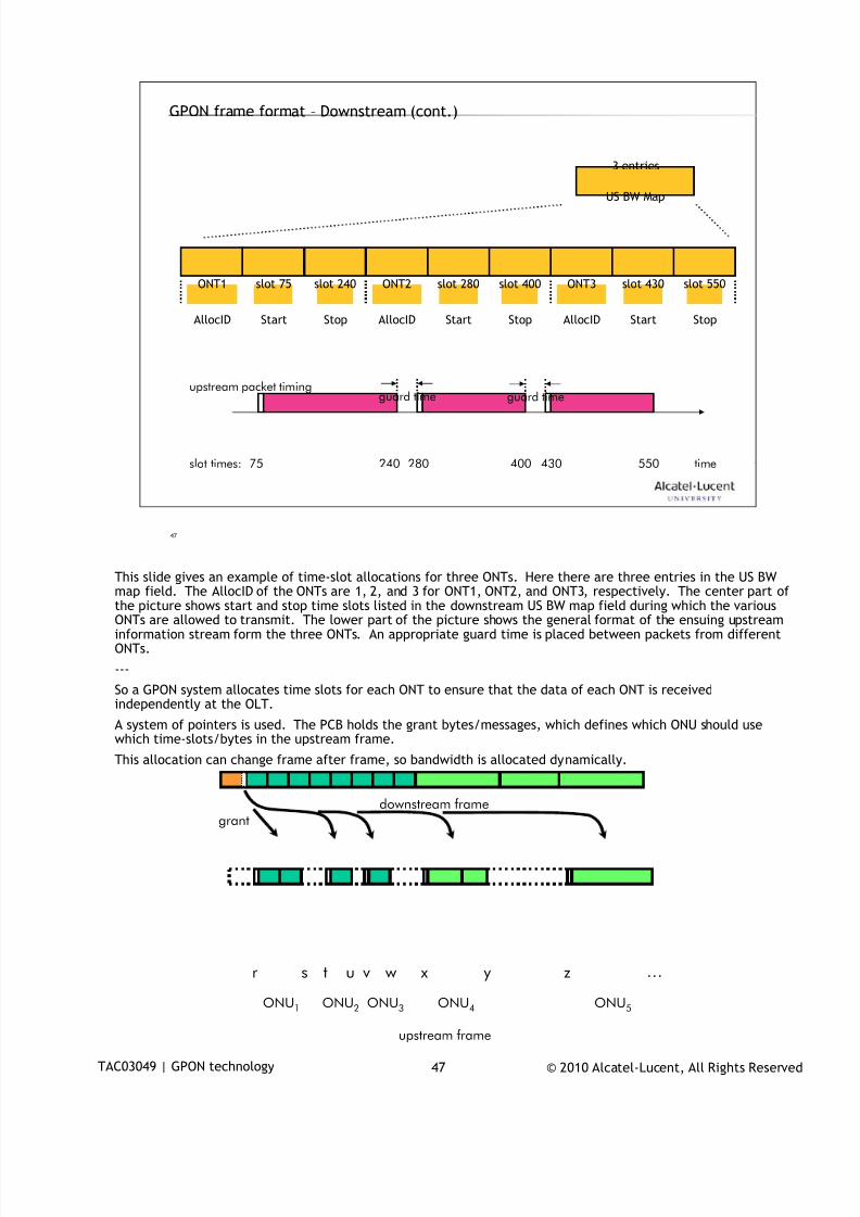
7/18/2019 Alu - A7302 Isam Fttu Operator Gpon Nant-e_ce-PDF
http://slidepdf.com/reader/full/alu-a7302-isam-fttu-operator-gpon-nant-ece-pdf 188/432
© 2010 Alcatel-Lucent, All Rights ReservedTAC03049 | GPON technology 47
47
GPON frame format – Downstream (cont.)
US BW Map
3 entries
ONT1 slot 75 slot 240
AllocID Start Stop
ONT2 slot 280 slot 400
AllocID Start Stop
ONT3 slot 430 slot 550
AllocID Start Stop
upstream packet timingguard timeguard time
75 240 280 400 430 550slot times: time
This slide gives an example of time-slot allocations for three ONTs. Here there are three entries in the US BW
map field. The AllocID of the ONTs are 1, 2, and 3 for ONT1, ONT2, and ONT3, respectively. The center part ofthe picture shows start and stop time slots listed in the downstream US BW map field during which the variousONTs are allowed to transmit. The lower part of the picture shows the general format of the ensuing upstreaminformation stream form the three ONTs. An appropriate guard time is placed between packets from differentONTs.
---
So a GPON system allocates time slots for each ONT to ensure that the data of each ONT is receivedindependently at the OLT.
A system of pointers is used. The PCB holds the grant bytes/messages, which defines which ONU should usewhich time-slots/bytes in the upstream frame.
This allocation can change frame after frame, so bandwidth is allocated dynamically.
ONU1 ONU2 ONU3 ONU4 ONU5
r s t
downstream frame
upstream frame
u v w x y z …
grant
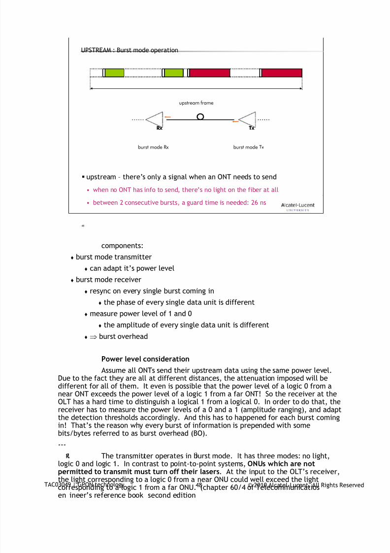
7/18/2019 Alu - A7302 Isam Fttu Operator Gpon Nant-e_ce-PDF
http://slidepdf.com/reader/full/alu-a7302-isam-fttu-operator-gpon-nant-ece-pdf 189/432
© 2010 Alcatel-Lucent, All Rights ReservedTAC03049 | GPON technology 48
48
UPSTREAM : Burst mode operation
upstream – there’s only a signal when an ONT needs to send• when no ONT has info to send, there’s no light on the fiber at all
• between 2 consecutive bursts, a guard time is needed: 26 ns
upstream frame
Rx Tx
burst mode Rx burst mode Tx
components:
burst mode transmitter
can adapt it’s power level burst mode receiver
resync on every single burst coming in
the phase of every single data unit is different
measure power level of 1 and 0
the amplitude of every single data unit is different
burst overhead
Power level considerationAssume all ONTs send their upstream data using the same power level.
Due to the fact they are all at different distances, the attenuation imposed will bedifferent for all of them. It even is possible that the power level of a logic 0 from anear ONT exceeds the power level of a logic 1 from a far ONT! So the receiver at theOLT has a hard time to distinguish a logical 1 from a logical 0. In order to do that, thereceiver has to measure the power levels of a 0 and a 1 (amplitude ranging), and adaptthe detection thresholds accordingly. And this has to happened for each burst comingin! That’s the reason why every burst of information is prepended with somebits/bytes referred to as burst overhead (BO).
---
The transmitter operates in burst mode. It has three modes: no light,logic 0 and logic 1. In contrast to point-to-point systems, ONUs which are notpermitted to transmit must turn off their lasers. At the input to the OLT’s receiver,the light corresponding to a logic 0 from a near ONU could well exceed the lightcorresponding to a logic 1 from a far ONU. (chapter 60/4 of Telecommunicatiosen ineer’s reference book second edition
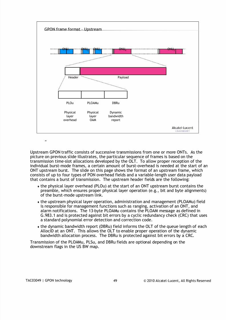
7/18/2019 Alu - A7302 Isam Fttu Operator Gpon Nant-e_ce-PDF
http://slidepdf.com/reader/full/alu-a7302-isam-fttu-operator-gpon-nant-ece-pdf 190/432
© 2010 Alcatel-Lucent, All Rights ReservedTAC03049 | GPON technology 49
49
GPON frame format – Upstream
ONU1 ONU2 ONU3 ONU4 ONU5
Header Payload
PLOu PLOAMu DBRu
Physical
layer
overhead
Physical
layer
OAM
Dynamic
bandwidth
report
Upstream GPON traffic consists of successive transmissions from one or more ONTs. As the
picture on previous slide illustrates, the particular sequence of frames is based on thetransmission time-slot allocations developed by the OLT. To allow proper reception of theindividual burst-mode frames, a certain amount of burst-overhead is needed at the start of anONT upstream burst. The slide on this page shows the format of an upstream frame, whichconsists of up to four types of PON overhead fields and a variable-length user data payloadthat contains a burst of transmission. The upstream header fields are the following:
the physical layer overhead (PLOu) at the start of an ONT upstream burst contains thepreamble, which ensures proper physical layer operation (e.g., bit and byte alignments)of the burst-mode upstream link.
the upstream physical layer operation, administration and management (PLOAMu) field
is responsible for management functions such as ranging, activation of an ONT, andalarm notifications. The 13-byte PLOAMu contains the PLOAM message as defined inG.983.1 and is protected against bit errors by a cyclic redundancy check (CRC) that usesa standard polynomial error detection and correction code.
the dynamic bandwidth report (DBRu) field informs the OLT of the queue length of eachAllocID at an ONT. This allows the OLT to enable proper operation of the dynamicbandwidth allocation process. The DBRu is protected against bit errors by a CRC.
Transmission of the PLOAMu, PLSu, and DBRu fields are optional depending on thedownstream flags in the US BW map.
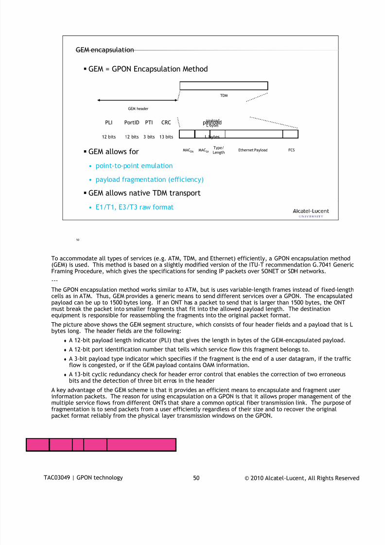
7/18/2019 Alu - A7302 Isam Fttu Operator Gpon Nant-e_ce-PDF
http://slidepdf.com/reader/full/alu-a7302-isam-fttu-operator-gpon-nant-ece-pdf 191/432
© 2010 Alcatel-Lucent, All Rights ReservedTAC03049 | GPON technology 50
50
GEM = GPON Encapsulation Method
GEM allows for
• point-to-point emulation
• payload fragmentation (efficiency)
GEM allows native TDM transport
• E1/T1, E3/T3 raw format
12 bits 13 bits12 bits 3 bits
TDM
Ethernet PayloadMACDA MACSA
Type/
LengthFCS
GEM header
GEM encapsulation
payload
L bytespayloadCRCPTIPortIDPLI
L bytes
To accommodate all types of services (e.g. ATM, TDM, and Ethernet) efficiently, a GPON encapsulation method
(GEM) is used. This method is based on a slightly modified version of the ITU-T recommendation G.7041 GenericFraming Procedure, which gives the specifications for sending IP packets over SONET or SDH networks.
---
The GPON encapsulation method works similar to ATM, but is uses variable-length frames instead of fixed-lengthcells as in ATM. Thus, GEM provides a generic means to send different services over a GPON. The encapsulatedpayload can be up to 1500 bytes long. If an ONT has a packet to send that is larger than 1500 bytes, the ONTmust break the packet into smaller fragments that fit into the allowed payload length. The destinationequipment is responsible for reassembling the fragments into the original packet format.
The picture above shows the GEM segment structure, which consists of four header fields and a payload that is Lbytes long. The header fields are the following:
A 12-bit payload length indicator (PLI) that gives the length in bytes of the GEM-encapsulated payload.
A 12-bit port identification number that tells which service flow this fragment belongs to.
A 3-bit payload type indicator which specifies if the fragment is the end of a user datagram, if the trafficflow is congested, or if the GEM payload contains OAM information.
A 13-bit cyclic redundancy check for header error control that enables the correction of two erroneousbits and the detection of three bit erros in the header
A key advantage of the GEM scheme is that it provides an efficient means to encapsulate and fragment userinformation packets. The reason for using encapsulation on a GPON is that it allows proper management of themultiple service flows from different ONTs that share a common optical fiber transmission link. The purpose offragmentation is to send packets from a user efficiently regardless of their size and to recover the originalpacket format reliably from the physical layer transmission windows on the GPON.

7/18/2019 Alu - A7302 Isam Fttu Operator Gpon Nant-e_ce-PDF
http://slidepdf.com/reader/full/alu-a7302-isam-fttu-operator-gpon-nant-ece-pdf 192/432
© 2010 Alcatel-Lucent, All Rights ReservedTAC03049 | GPON technology 51
51
www.alcatel-lucent.comwww.alcatel-lucent.com

7/18/2019 Alu - A7302 Isam Fttu Operator Gpon Nant-e_ce-PDF
http://slidepdf.com/reader/full/alu-a7302-isam-fttu-operator-gpon-nant-ece-pdf 193/432
© 2010 Alcatel-Lucent, All Rights ReservedTAC03049-HO10 1
GPON basic configuration
During class please switch off your mobile, pager or other that may interrupt.
7/18/2019 Alu - A7302 Isam Fttu Operator Gpon Nant-e_ce-PDF
http://slidepdf.com/reader/full/alu-a7302-isam-fttu-operator-gpon-nant-ece-pdf 194/432
© 2010 Alcatel-Lucent, All Rights ReservedTAC03049-HO10 2
2
At the end of this session, you will …
know what functions the NGLT-x is performing
be capable to configure ONTs
Objective
7/18/2019 Alu - A7302 Isam Fttu Operator Gpon Nant-e_ce-PDF
http://slidepdf.com/reader/full/alu-a7302-isam-fttu-operator-gpon-nant-ece-pdf 195/432
© 2010 Alcatel-Lucent, All Rights ReservedTAC03049-HO10 3
3
Table of Contents
1.PON provisioning
2.ONT provisioning
3.ONTCARD provisioning
4.ONTENET provisioning
5.Bridge port configuring

7/18/2019 Alu - A7302 Isam Fttu Operator Gpon Nant-e_ce-PDF
http://slidepdf.com/reader/full/alu-a7302-isam-fttu-operator-gpon-nant-ece-pdf 196/432
© 2010 Alcatel-Lucent, All Rights ReservedTAC03049-HO10 4
4
Remember this?0
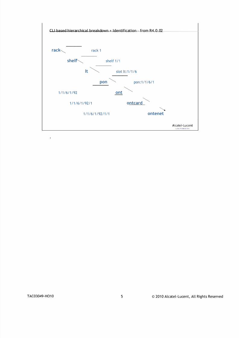
7/18/2019 Alu - A7302 Isam Fttu Operator Gpon Nant-e_ce-PDF
http://slidepdf.com/reader/full/alu-a7302-isam-fttu-operator-gpon-nant-ece-pdf 197/432
© 2010 Alcatel-Lucent, All Rights ReservedTAC03049-HO10 5
5
CLI based hierarchical breakdown + Identification – from R4.0.02
rack
shelf
pon
ont
ontenet
lt
ontcard
slot lt:1/1/6
pon:1/1/6/1
1/1/6/1/92
1/1/6/1/92/1
1/1/6/1/92/1/1
shelf 1/1
rack 1
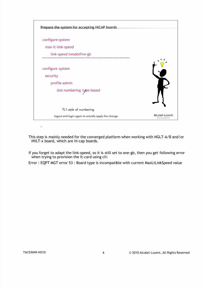
7/18/2019 Alu - A7302 Isam Fttu Operator Gpon Nant-e_ce-PDF
http://slidepdf.com/reader/full/alu-a7302-isam-fttu-operator-gpon-nant-ece-pdf 198/432
© 2010 Alcatel-Lucent, All Rights ReservedTAC03049-HO10 6
6
Prepare the system for accepting HiCAP boards
configure system
max-lt-link-speed
link-speed twodotfive-gb
configure system
security
profile admin
slot-numbering type-based
TL1-style of numbering
logout and login again to actually apply this change
This step is mainly needed for the converged platform when working with NGLT-A/B and/or
NVLT-x board, which are hi-cap boards.
If you forget to adapt the link-speed, so it is still set to one-gb, then you get following errorwhen trying to provision the lt-card using cli:
Error : EQPT MGT error 53 : Board type is incompatible with current MaxLtLinkSpeed value
7/18/2019 Alu - A7302 Isam Fttu Operator Gpon Nant-e_ce-PDF
http://slidepdf.com/reader/full/alu-a7302-isam-fttu-operator-gpon-nant-ece-pdf 199/432
© 2010 Alcatel-Lucent, All Rights ReservedTAC03049-HO10 7
7
PON provisioning1
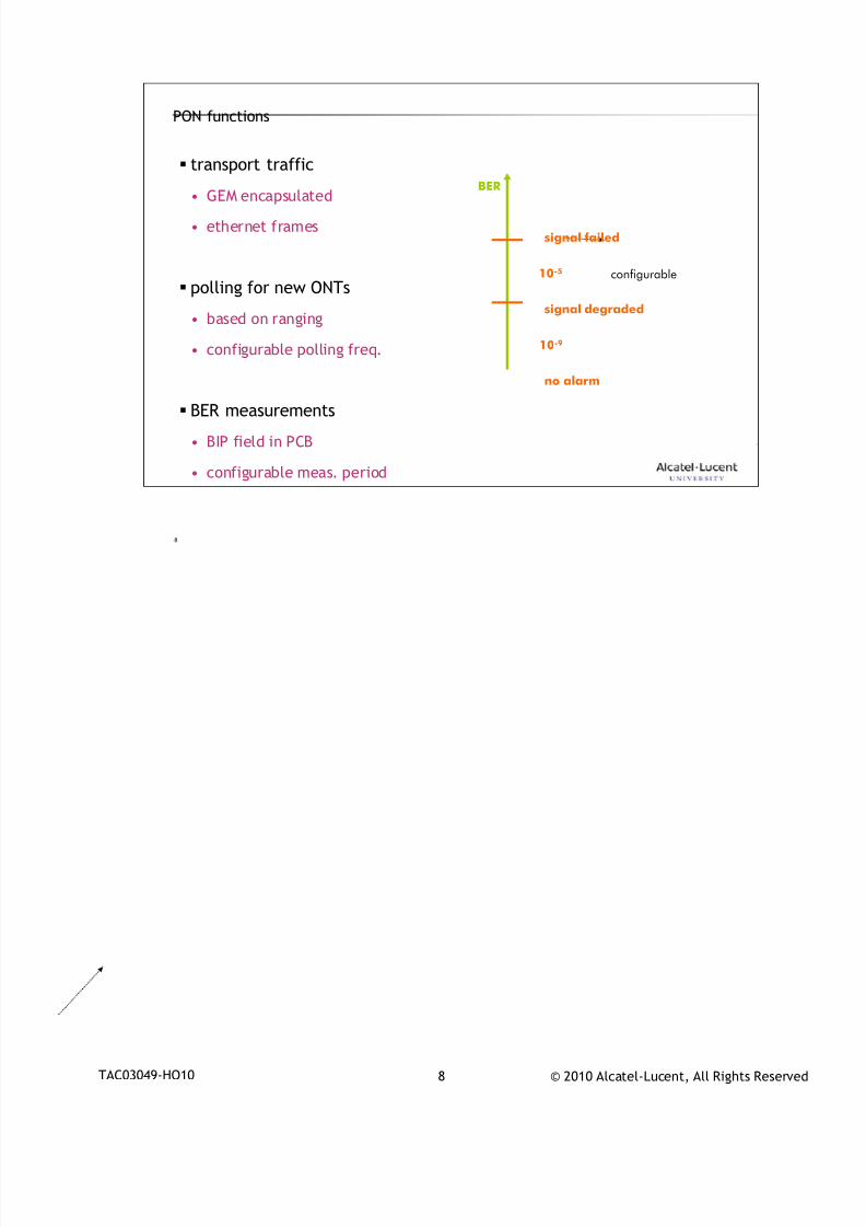
7/18/2019 Alu - A7302 Isam Fttu Operator Gpon Nant-e_ce-PDF
http://slidepdf.com/reader/full/alu-a7302-isam-fttu-operator-gpon-nant-ece-pdf 200/432
© 2010 Alcatel-Lucent, All Rights ReservedTAC03049-HO10 8
8
PON functions
transport traffic
• GEM encapsulated
• ethernet frames
polling for new ONTs
• based on ranging
• configurable polling freq.
BER measurements
• BIP field in PCB
• configurable meas. period
BER
10-5
10-9
no alarm
signal degraded
signal failed
configurable
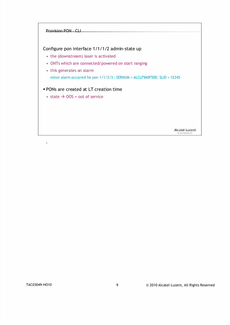
7/18/2019 Alu - A7302 Isam Fttu Operator Gpon Nant-e_ce-PDF
http://slidepdf.com/reader/full/alu-a7302-isam-fttu-operator-gpon-nant-ece-pdf 201/432
© 2010 Alcatel-Lucent, All Rights ReservedTAC03049-HO10 9
9
Provision PON – CLI
Configure pon interface 1/1/1/2 admin-state up
• the (downstream) laser is activated
• ONTs which are connected/powered on start ranging
• this generates an alarm
minor alarm occurred for pon 1/1/3/3 : SERNUM = ALCLF9A0F50D, SLID = 12345
PONs are created at LT creation time
• state OOS = out of service
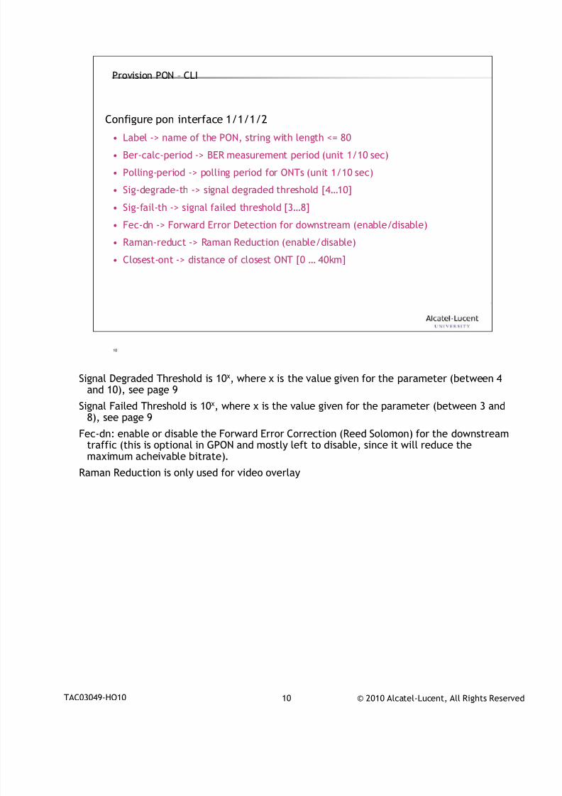
7/18/2019 Alu - A7302 Isam Fttu Operator Gpon Nant-e_ce-PDF
http://slidepdf.com/reader/full/alu-a7302-isam-fttu-operator-gpon-nant-ece-pdf 202/432
© 2010 Alcatel-Lucent, All Rights ReservedTAC03049-HO10 10
10
Provision PON – CLI
Configure pon interface 1/1/1/2
• Label -> name of the PON, string with length <= 80
• Ber-calc-period -> BER measurement period (unit 1/10 sec)
• Polling-period -> polling period for ONTs (unit 1/10 sec)
• Sig-degrade-th -> signal degraded threshold [4…10]
• Sig-fail-th -> signal failed threshold [3…8]
• Fec-dn -> Forward Error Detection for downstream (enable/disable)
• Raman-reduct -> Raman Reduction (enable/disable)
• Closest-ont -> distance of closest ONT [0 … 40km]
Signal Degraded Threshold is 10x, where x is the value given for the parameter (between 4
and 10), see page 9
Signal Failed Threshold is 10x, where x is the value given for the parameter (between 3 and8), see page 9
Fec-dn: enable or disable the Forward Error Correction (Reed Solomon) for the downstreamtraffic (this is optional in GPON and mostly left to disable, since it will reduce themaximum acheivable bitrate).
Raman Reduction is only used for video overlay
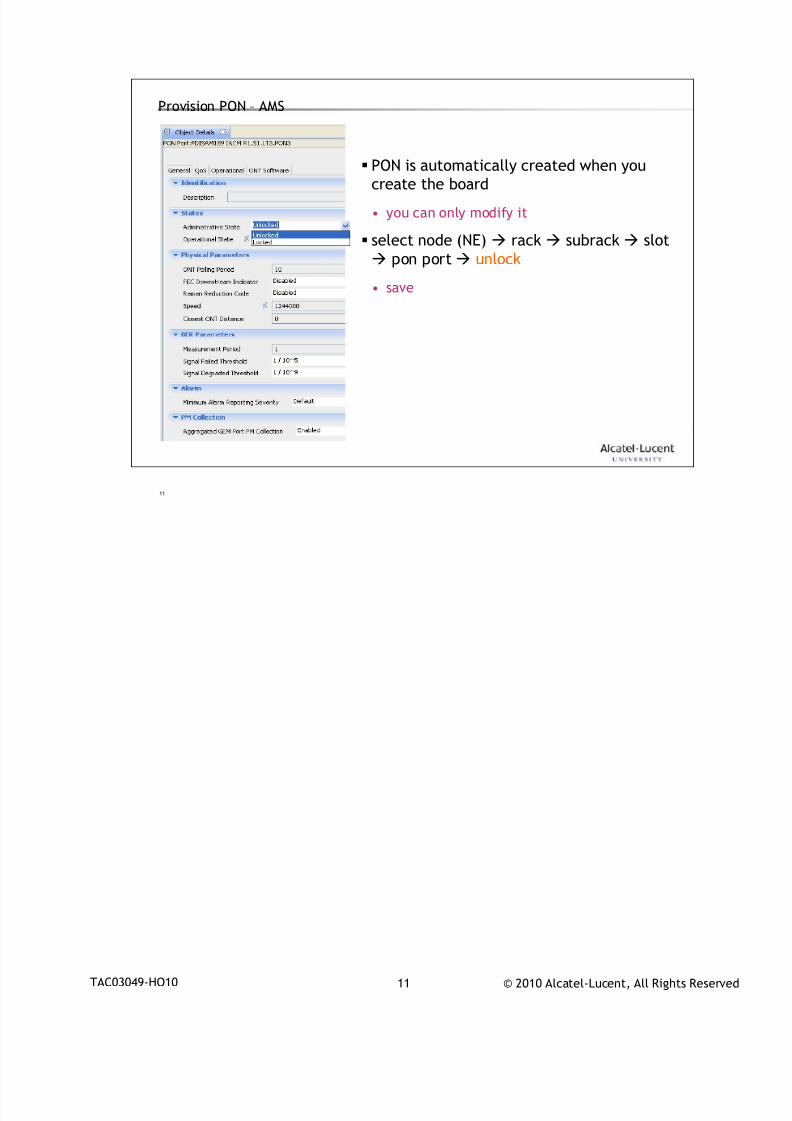
7/18/2019 Alu - A7302 Isam Fttu Operator Gpon Nant-e_ce-PDF
http://slidepdf.com/reader/full/alu-a7302-isam-fttu-operator-gpon-nant-ece-pdf 203/432
© 2010 Alcatel-Lucent, All Rights ReservedTAC03049-HO10 11
11
Provision PON – AMS
PON is automatically created when you
create the board
• you can only modify it
select node (NE) rack subrack slot
pon port unlock
• save

7/18/2019 Alu - A7302 Isam Fttu Operator Gpon Nant-e_ce-PDF
http://slidepdf.com/reader/full/alu-a7302-isam-fttu-operator-gpon-nant-ece-pdf 204/432
© 2010 Alcatel-Lucent, All Rights ReservedTAC03049-HO10 12
12
ONT provisioning2
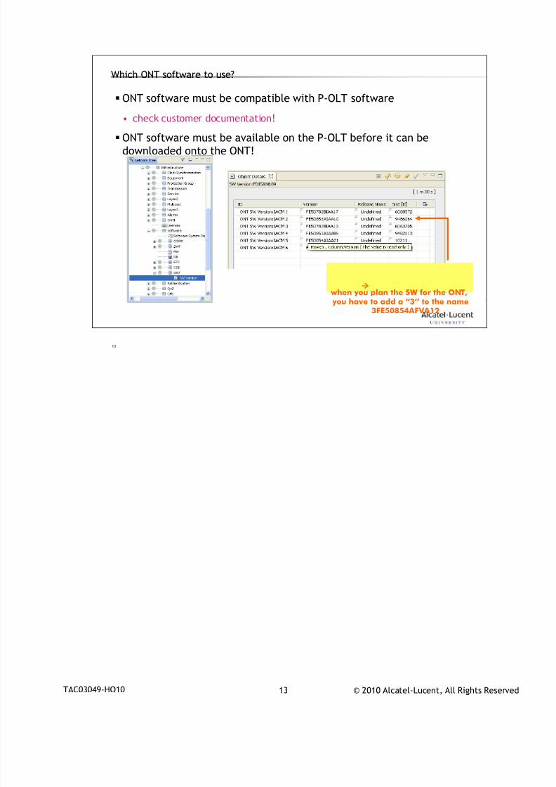
7/18/2019 Alu - A7302 Isam Fttu Operator Gpon Nant-e_ce-PDF
http://slidepdf.com/reader/full/alu-a7302-isam-fttu-operator-gpon-nant-ece-pdf 205/432
© 2010 Alcatel-Lucent, All Rights ReservedTAC03049-HO10 13
13
Which ONT software to use?
ONT software must be compatible with P-OLT software
• check customer documentation!
ONT software must be available on the P-OLT before it can be
downloaded onto the ONT!
when you plan the SW for the ONT, you have to add a “3’’ to the name
3FE50854AFVA12

7/18/2019 Alu - A7302 Isam Fttu Operator Gpon Nant-e_ce-PDF
http://slidepdf.com/reader/full/alu-a7302-isam-fttu-operator-gpon-nant-ece-pdf 206/432
© 2010 Alcatel-Lucent, All Rights ReservedTAC03049-HO10 14
14
ONT software banks
active bank
passive bank
RAM
planned software what you intend to run in RAMactive sw what is actually running in RAMpassive sw what is in the passive bank
active bank:what the ONTtries to boot up with
if the ONT fails toboot with what isin the active bank
it will use thepassive bank
if the active software is different from the planned, the P-OLT tries todownload the planned software to the passive bank
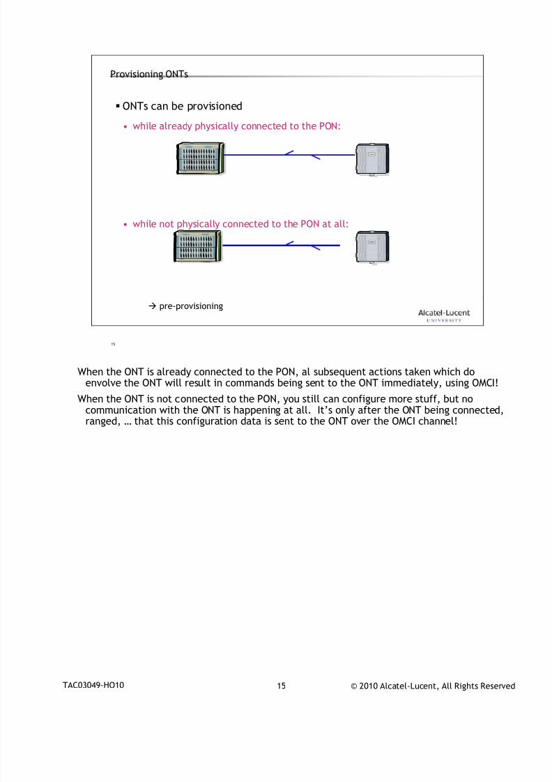
7/18/2019 Alu - A7302 Isam Fttu Operator Gpon Nant-e_ce-PDF
http://slidepdf.com/reader/full/alu-a7302-isam-fttu-operator-gpon-nant-ece-pdf 207/432
© 2010 Alcatel-Lucent, All Rights ReservedTAC03049-HO10 15
15
Provisioning ONTs
ONTs can be provisioned
• while already physically connected to the PON:
• while not physically connected to the PON at all:
pre-provisioning
When the ONT is already connected to the PON, al subsequent actions taken which do
envolve the ONT will result in commands being sent to the ONT immediately, using OMCI!
When the ONT is not connected to the PON, you still can configure more stuff, but nocommunication with the ONT is happening at all. It’s only after the ONT being connected,ranged, … that this configuration data is sent to the ONT over the OMCI channel!
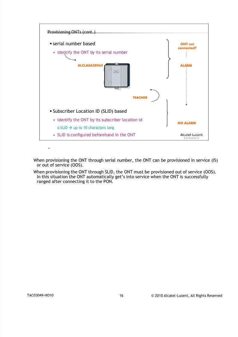
7/18/2019 Alu - A7302 Isam Fttu Operator Gpon Nant-e_ce-PDF
http://slidepdf.com/reader/full/alu-a7302-isam-fttu-operator-gpon-nant-ece-pdf 208/432
© 2010 Alcatel-Lucent, All Rights ReservedTAC03049-HO10 16
16
Provisioning ONTs (cont.)
serial number based
• identify the ONT by its serial number
Subscriber Location ID (SLID) based
• identify the ONT by its subscriber location id
o SLID up to 10 characters long
• SLID is configured beforehand in the ONT
TEACHER
ALCLA0A28965
ONT notconnected?
NO ALARM
ALARM
When provisioning the ONT through serial number, the ONT can be provisioned in service (IS)
or out of service (OOS).
When provisioning the ONT through SLID, the ONT must be provisioned out of service (OOS).In this situation the ONT automatically get’s into service when the ONT is successfullyranged after connecting it to the PON.
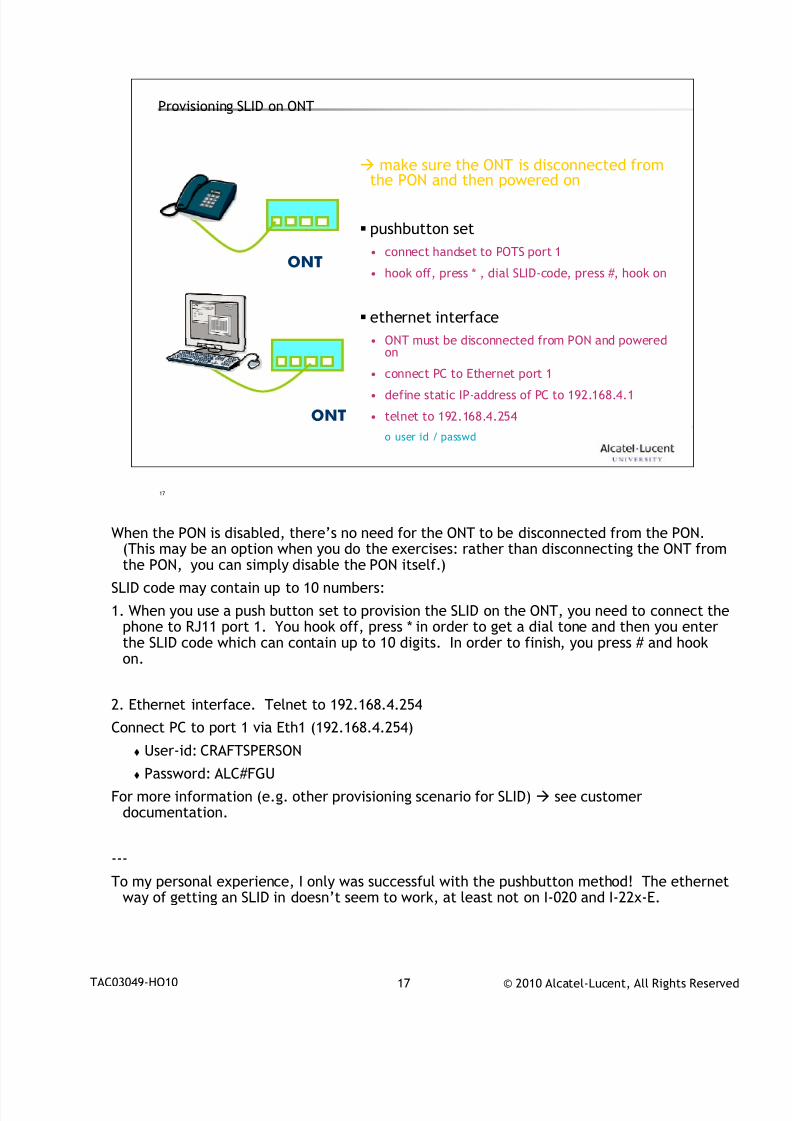
7/18/2019 Alu - A7302 Isam Fttu Operator Gpon Nant-e_ce-PDF
http://slidepdf.com/reader/full/alu-a7302-isam-fttu-operator-gpon-nant-ece-pdf 209/432
© 2010 Alcatel-Lucent, All Rights ReservedTAC03049-HO10 17
17
Provisioning SLID on ONT
make sure the ONT is disconnected from
the PON and then powered on
pushbutton set
• connect handset to POTS port 1
• hook off, press * , dial SLID-code, press #, hook on
ethernet interface
• ONT must be disconnected from PON and poweredon
• connect PC to Ethernet port 1
• define static IP-address of PC to 192.168.4.1
• telnet to 192.168.4.254
o user id / passwd
ONT
ONT
When the PON is disabled, there’s no need for the ONT to be disconnected from the PON.
(This may be an option when you do the exercises: rather than disconnecting the ONT fromthe PON, you can simply disable the PON itself.)
SLID code may contain up to 10 numbers:
1. When you use a push button set to provision the SLID on the ONT, you need to connect thephone to RJ11 port 1. You hook off, press * in order to get a dial tone and then you enterthe SLID code which can contain up to 10 digits. In order to finish, you press # and hookon.
2. Ethernet interface. Telnet to 192.168.4.254
Connect PC to port 1 via Eth1 (192.168.4.254) User-id: CRAFTSPERSON
Password: ALC#FGU
For more information (e.g. other provisioning scenario for SLID) see customerdocumentation.
---
To my personal experience, I only was successful with the pushbutton method! The ethernetway of getting an SLID in doesn’t seem to work, at least not on I-020 and I-22x-E.
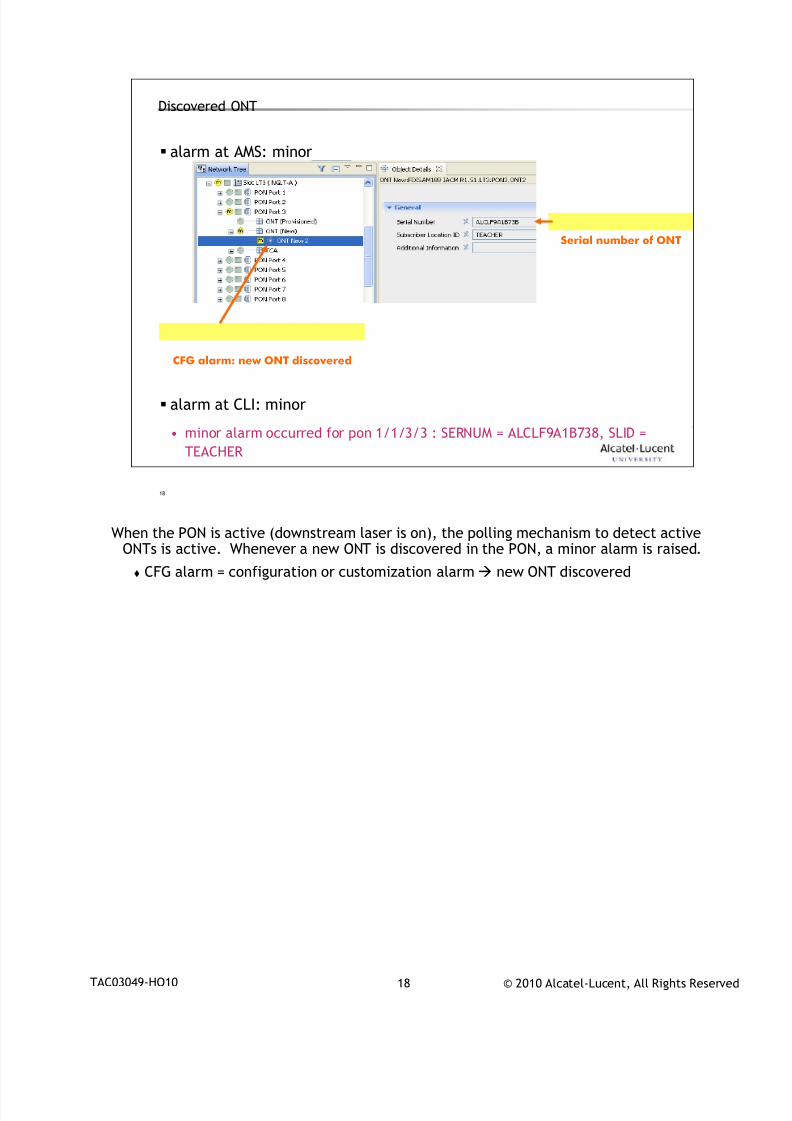
7/18/2019 Alu - A7302 Isam Fttu Operator Gpon Nant-e_ce-PDF
http://slidepdf.com/reader/full/alu-a7302-isam-fttu-operator-gpon-nant-ece-pdf 210/432
© 2010 Alcatel-Lucent, All Rights ReservedTAC03049-HO10 18
18
Discovered ONT
alarm at AMS: minor
alarm at CLI: minor
• minor alarm occurred for pon 1/1/3/3 : SERNUM = ALCLF9A1B738, SLID =
TEACHER
CFG alarm: new ONT discovered
Serial number of ONT
When the PON is active (downstream laser is on), the polling mechanism to detect active
ONTs is active. Whenever a new ONT is discovered in the PON, a minor alarm is raised.
CFG alarm = configuration or customization alarm new ONT discovered
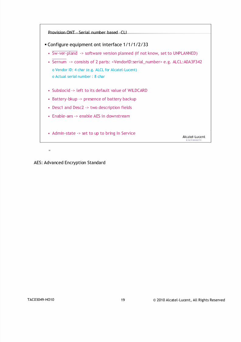
7/18/2019 Alu - A7302 Isam Fttu Operator Gpon Nant-e_ce-PDF
http://slidepdf.com/reader/full/alu-a7302-isam-fttu-operator-gpon-nant-ece-pdf 211/432
© 2010 Alcatel-Lucent, All Rights ReservedTAC03049-HO10 19
19
Provision ONT – Serial number based –CLI
Configure equipment ont interface 1/1/1/2/33
• Sw-ver-pland -> software version planned (if not know, set to UNPLANNED)• Sernum -> consists of 2 parts: <VendorID:serial_number> e.g. ALCL:A0A3F342
o Vendor ID: 4 char (e.g. ALCL for Alcatel-Lucent)
o Actual serial number : 8 char
• Subslocid -> left to its default value of WILDCARD
• Battery-bkup -> presence of battery backup
• Desc1 and Desc2 -> two description fields
• Enable-aes -> enable AES in downstream
• Admin-state -> set to up to bring In Service
AES: Advanced Encryption Standard
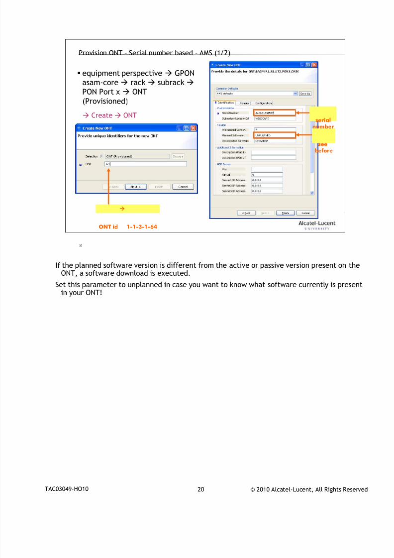
7/18/2019 Alu - A7302 Isam Fttu Operator Gpon Nant-e_ce-PDF
http://slidepdf.com/reader/full/alu-a7302-isam-fttu-operator-gpon-nant-ece-pdf 212/432
© 2010 Alcatel-Lucent, All Rights ReservedTAC03049-HO10 20
20
Provision ONT – Serial number based – AMS (1/2)
equipment perspective GPON
asam-core rack subrack
PON Port x ONT(Provisioned)
Create ONT
ONT id 1-1-3-1-64
serialnumber
seebefore
If the planned software version is different from the active or passive version present on the
ONT, a software download is executed.
Set this parameter to unplanned in case you want to know what software currently is presentin your ONT!
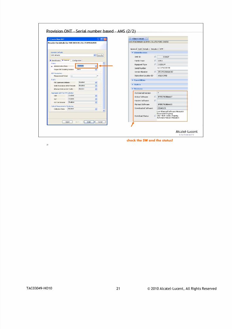
7/18/2019 Alu - A7302 Isam Fttu Operator Gpon Nant-e_ce-PDF
http://slidepdf.com/reader/full/alu-a7302-isam-fttu-operator-gpon-nant-ece-pdf 213/432
© 2010 Alcatel-Lucent, All Rights ReservedTAC03049-HO10 21
21
Provision ONT – Serial number based – AMS (2/2)
check the SW and the status!
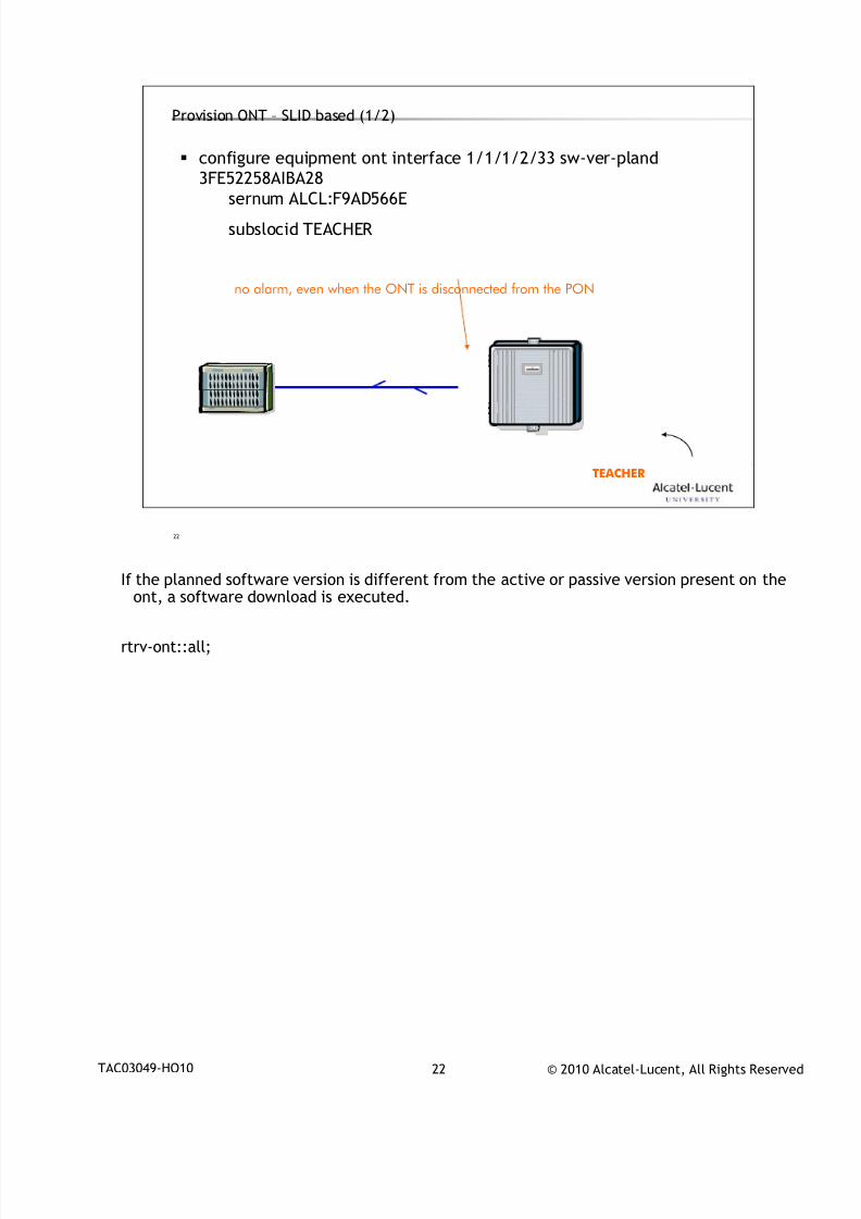
7/18/2019 Alu - A7302 Isam Fttu Operator Gpon Nant-e_ce-PDF
http://slidepdf.com/reader/full/alu-a7302-isam-fttu-operator-gpon-nant-ece-pdf 214/432
© 2010 Alcatel-Lucent, All Rights ReservedTAC03049-HO10 22
22
Provision ONT – SLID based (1/2)
configure equipment ont interface 1/1/1/2/33 sw-ver-pland
3FE52258AIBA28
sernum ALCL:F9AD566E
subslocid TEACHER
TEACHER
no alarm, even when the ONT is disconnected from the PON
If the planned software version is different from the active or passive version present on the
ont, a software download is executed.
rtrv-ont::all;
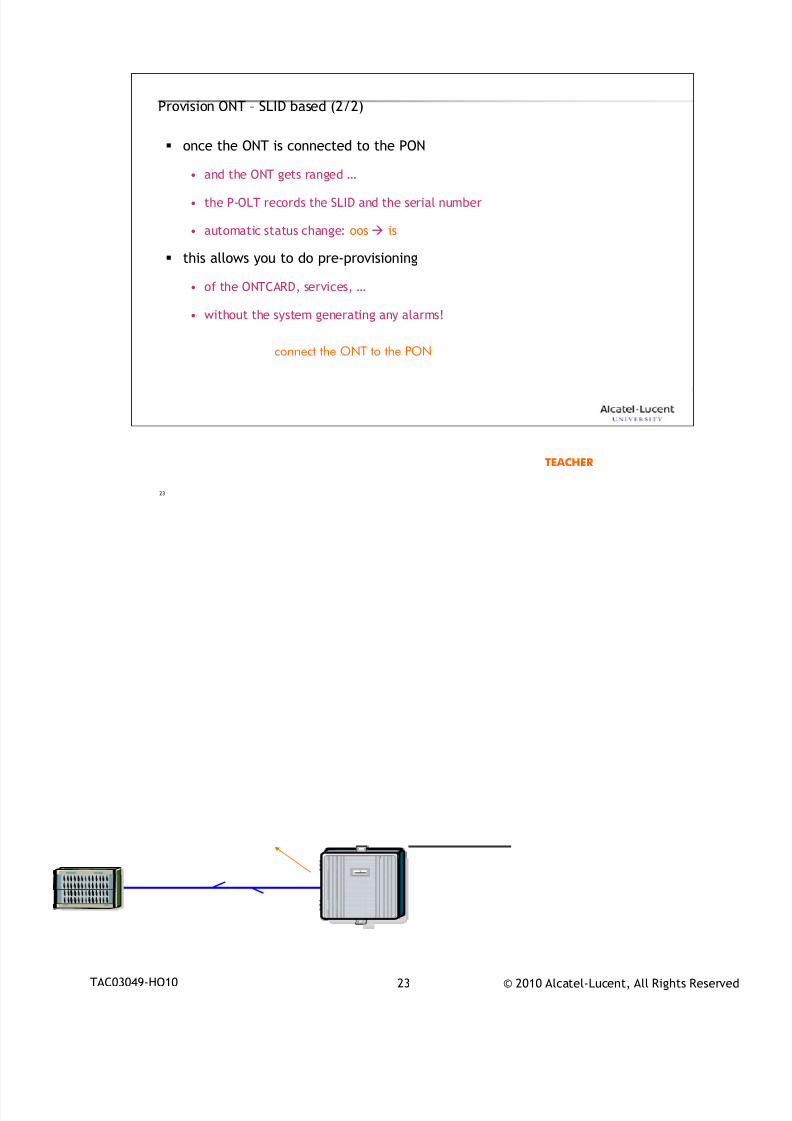
7/18/2019 Alu - A7302 Isam Fttu Operator Gpon Nant-e_ce-PDF
http://slidepdf.com/reader/full/alu-a7302-isam-fttu-operator-gpon-nant-ece-pdf 215/432
© 2010 Alcatel-Lucent, All Rights ReservedTAC03049-HO10 23
23
Provision ONT – SLID based (2/2)
once the ONT is connected to the PON
• and the ONT gets ranged …
• the P-OLT records the SLID and the serial number
• automatic status change: oos is
this allows you to do pre-provisioning
• of the ONTCARD, services, …
• without the system generating any alarms!
TEACHER
connect the ONT to the PON
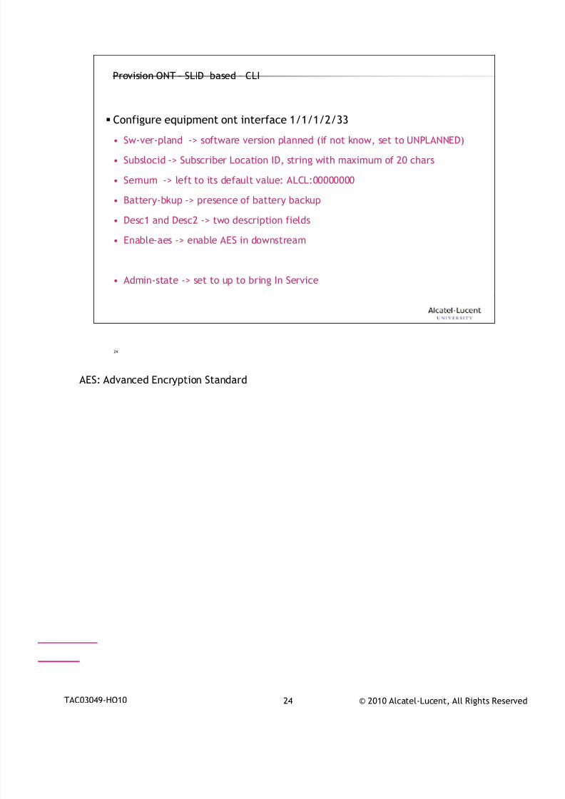
7/18/2019 Alu - A7302 Isam Fttu Operator Gpon Nant-e_ce-PDF
http://slidepdf.com/reader/full/alu-a7302-isam-fttu-operator-gpon-nant-ece-pdf 216/432
© 2010 Alcatel-Lucent, All Rights ReservedTAC03049-HO10 24
24
Provision ONT – SLID based – CLI
Configure equipment ont interface 1/1/1/2/33
• Sw-ver-pland -> software version planned (if not know, set to UNPLANNED)
• Subslocid -> Subscriber Location ID, string with maximum of 20 chars
• Sernum -> left to its default value: ALCL:00000000
• Battery-bkup -> presence of battery backup
• Desc1 and Desc2 -> two description fields
• Enable-aes -> enable AES in downstream
• Admin-state -> set to up to bring In Service
AES: Advanced Encryption Standard
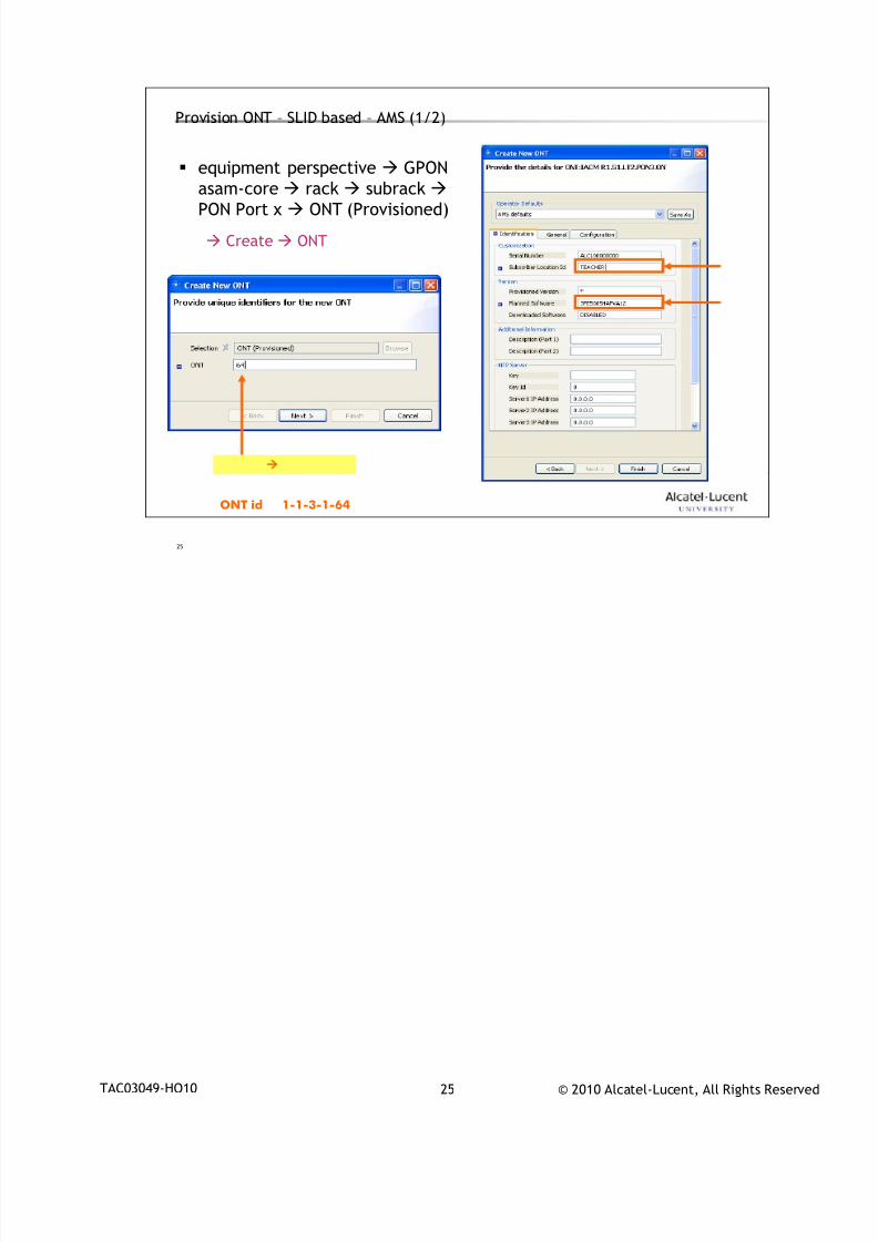
7/18/2019 Alu - A7302 Isam Fttu Operator Gpon Nant-e_ce-PDF
http://slidepdf.com/reader/full/alu-a7302-isam-fttu-operator-gpon-nant-ece-pdf 217/432
© 2010 Alcatel-Lucent, All Rights ReservedTAC03049-HO10 25
25
Provision ONT – SLID based – AMS (1/2)
equipment perspective GPON
asam-core rack subrack
PON Port x ONT (Provisioned)
Create ONT
ONT id 1-1-3-1-64
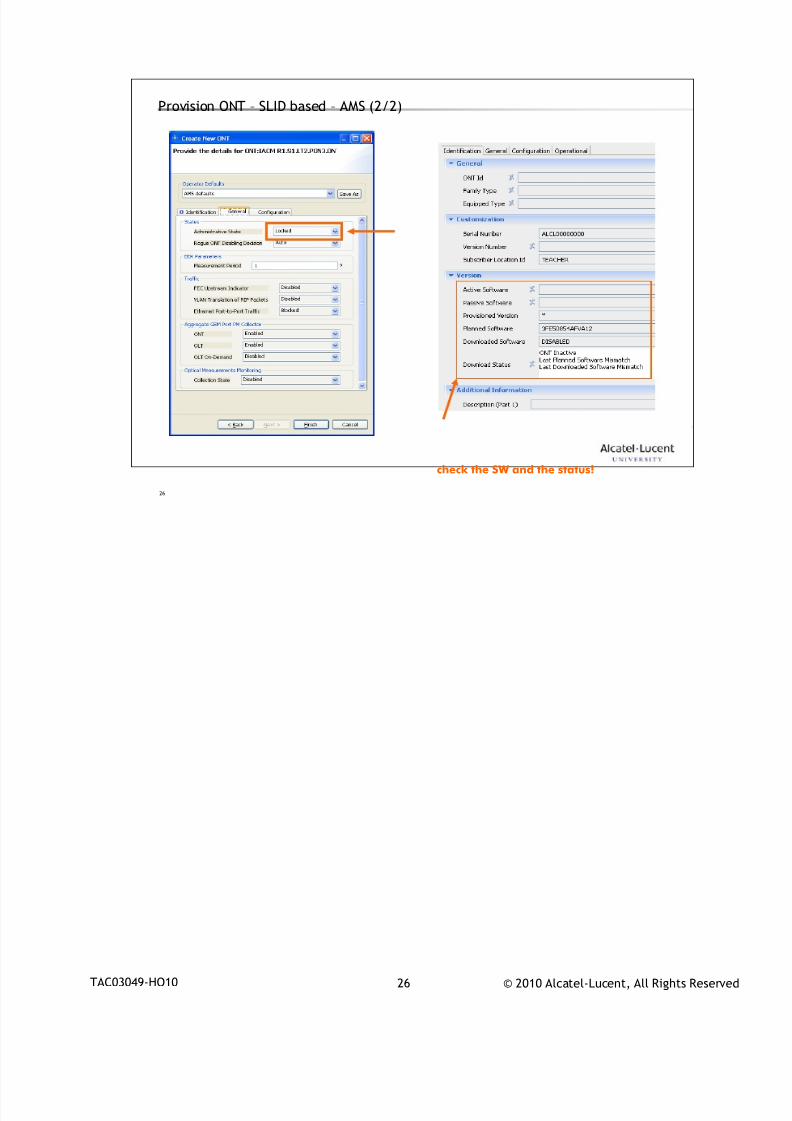
7/18/2019 Alu - A7302 Isam Fttu Operator Gpon Nant-e_ce-PDF
http://slidepdf.com/reader/full/alu-a7302-isam-fttu-operator-gpon-nant-ece-pdf 218/432
© 2010 Alcatel-Lucent, All Rights ReservedTAC03049-HO10 26
26
Provision ONT – SLID based – AMS (2/2)
check the SW and the status!
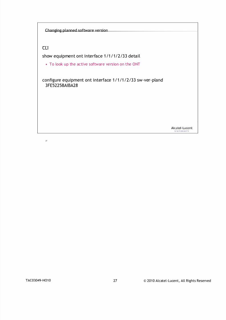
7/18/2019 Alu - A7302 Isam Fttu Operator Gpon Nant-e_ce-PDF
http://slidepdf.com/reader/full/alu-a7302-isam-fttu-operator-gpon-nant-ece-pdf 219/432
© 2010 Alcatel-Lucent, All Rights ReservedTAC03049-HO10 27
27
Changing planned software version
CLI
show equipment ont interface 1/1/1/2/33 detail
• To look up the active software version on the ONT
configure equipment ont interface 1/1/1/2/33 sw-ver-pland
3FE52258AIBA28
7/18/2019 Alu - A7302 Isam Fttu Operator Gpon Nant-e_ce-PDF
http://slidepdf.com/reader/full/alu-a7302-isam-fttu-operator-gpon-nant-ece-pdf 220/432
© 2010 Alcatel-Lucent, All Rights ReservedTAC03049-HO10 28
28
ONTCARD provisioning3
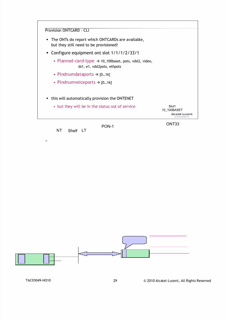
7/18/2019 Alu - A7302 Isam Fttu Operator Gpon Nant-e_ce-PDF
http://slidepdf.com/reader/full/alu-a7302-isam-fttu-operator-gpon-nant-ece-pdf 221/432
© 2010 Alcatel-Lucent, All Rights ReservedTAC03049-HO10 29
29
Provision ONTCARD - CLI
The ONTs do report which ONTCARDs are available,
but they still need to be provisioned!
Configure equipment ont slot 1/1/1/2/33/1
• Planned-card-type 10_100baset, pots, vdsl2, video,
ds1, e1, vdsl2pots, ethpots
• Plndnumdataports [0…16]
• Plndnumvoiceports [0…16]
this will automatically provision the ONTENET
• but they will be in the status out of service
Shelf NT LTPON-1
ONT33
Slot1
10_100BASET
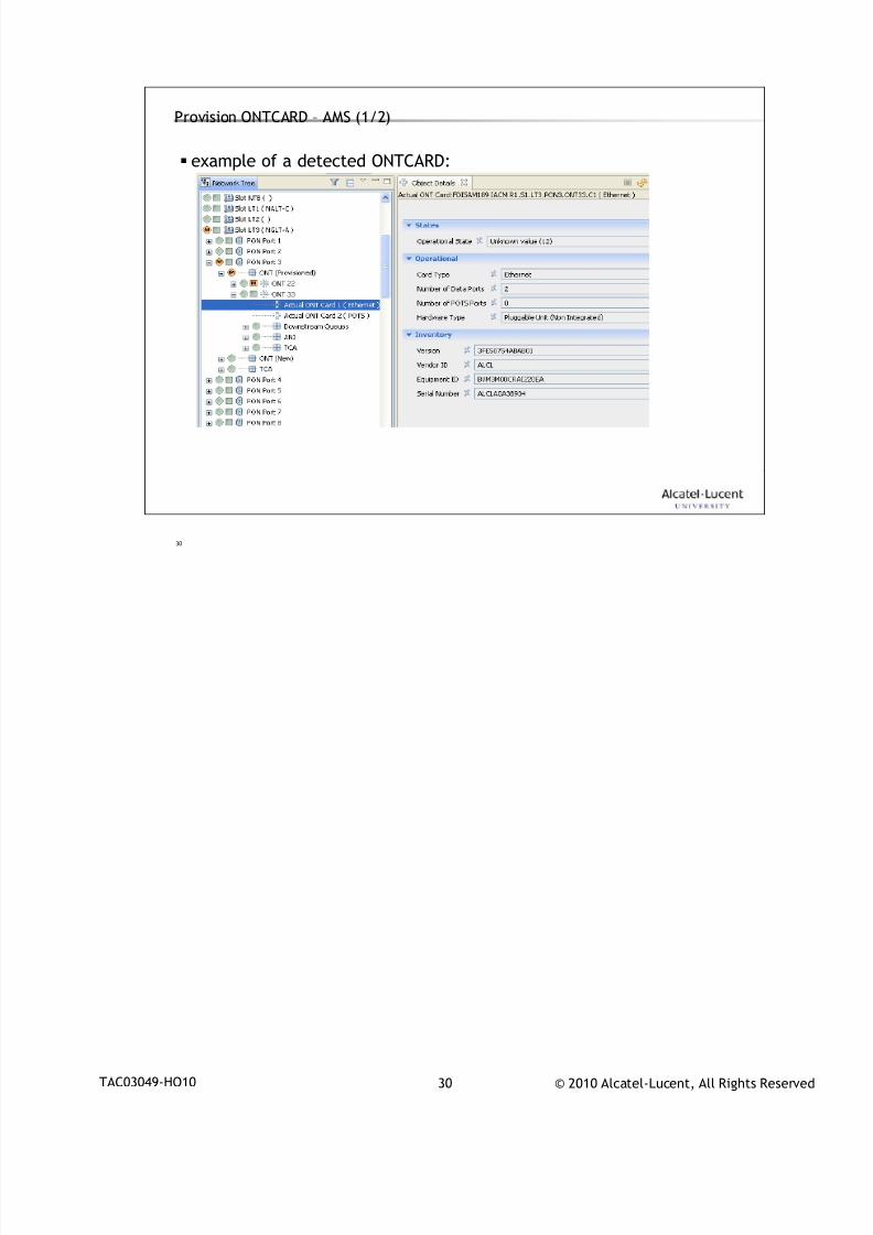
7/18/2019 Alu - A7302 Isam Fttu Operator Gpon Nant-e_ce-PDF
http://slidepdf.com/reader/full/alu-a7302-isam-fttu-operator-gpon-nant-ece-pdf 222/432
© 2010 Alcatel-Lucent, All Rights ReservedTAC03049-HO10 30
30
Provision ONTCARD – AMS (1/2)
example of a detected ONTCARD:
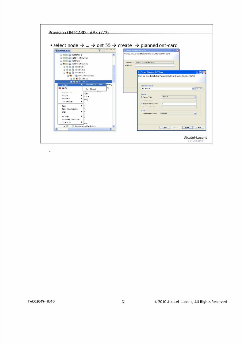
7/18/2019 Alu - A7302 Isam Fttu Operator Gpon Nant-e_ce-PDF
http://slidepdf.com/reader/full/alu-a7302-isam-fttu-operator-gpon-nant-ece-pdf 223/432
© 2010 Alcatel-Lucent, All Rights ReservedTAC03049-HO10 31
31
Provision ONTCARD – AMS (2/2)
select node … ont 55 create planned ont-card

7/18/2019 Alu - A7302 Isam Fttu Operator Gpon Nant-e_ce-PDF
http://slidepdf.com/reader/full/alu-a7302-isam-fttu-operator-gpon-nant-ece-pdf 224/432
© 2010 Alcatel-Lucent, All Rights ReservedTAC03049-HO10 32
32
ONTENET provisioning4
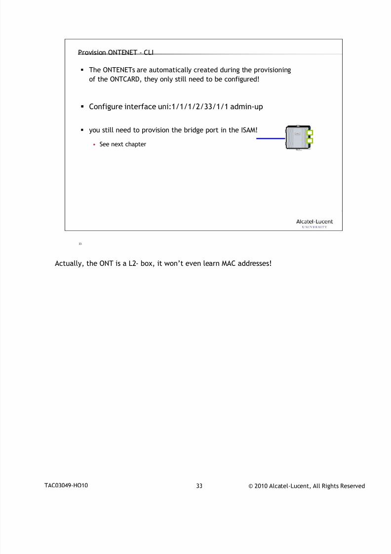
7/18/2019 Alu - A7302 Isam Fttu Operator Gpon Nant-e_ce-PDF
http://slidepdf.com/reader/full/alu-a7302-isam-fttu-operator-gpon-nant-ece-pdf 225/432
© 2010 Alcatel-Lucent, All Rights ReservedTAC03049-HO10 33
33
Provision ONTENET - CLI
The ONTENETs are automatically created during the provisioning
of the ONTCARD, they only still need to be configured!
Configure interface uni:1/1/1/2/33/1/1 admin-up
you still need to provision the bridge port in the ISAM!
• See next chapter
Actually, the ONT is a L2- box, it won’t even learn MAC addresses!
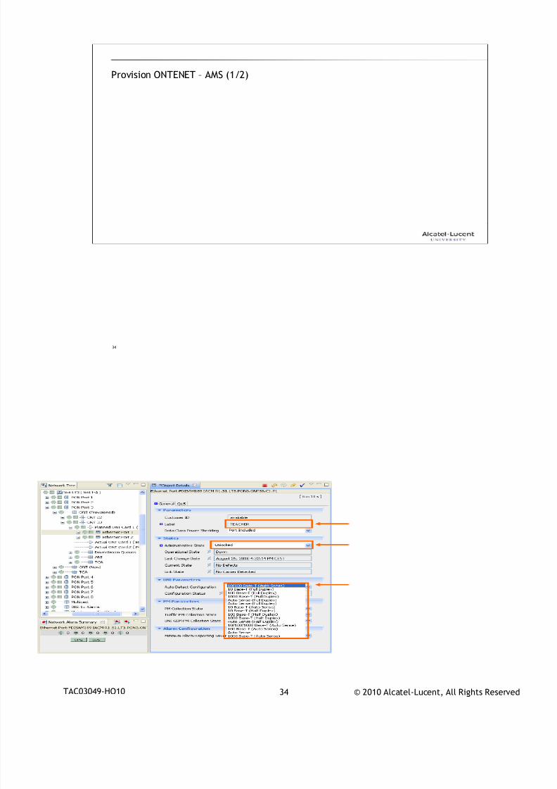
7/18/2019 Alu - A7302 Isam Fttu Operator Gpon Nant-e_ce-PDF
http://slidepdf.com/reader/full/alu-a7302-isam-fttu-operator-gpon-nant-ece-pdf 226/432
© 2010 Alcatel-Lucent, All Rights ReservedTAC03049-HO10 34
34
Provision ONTENET – AMS (1/2)
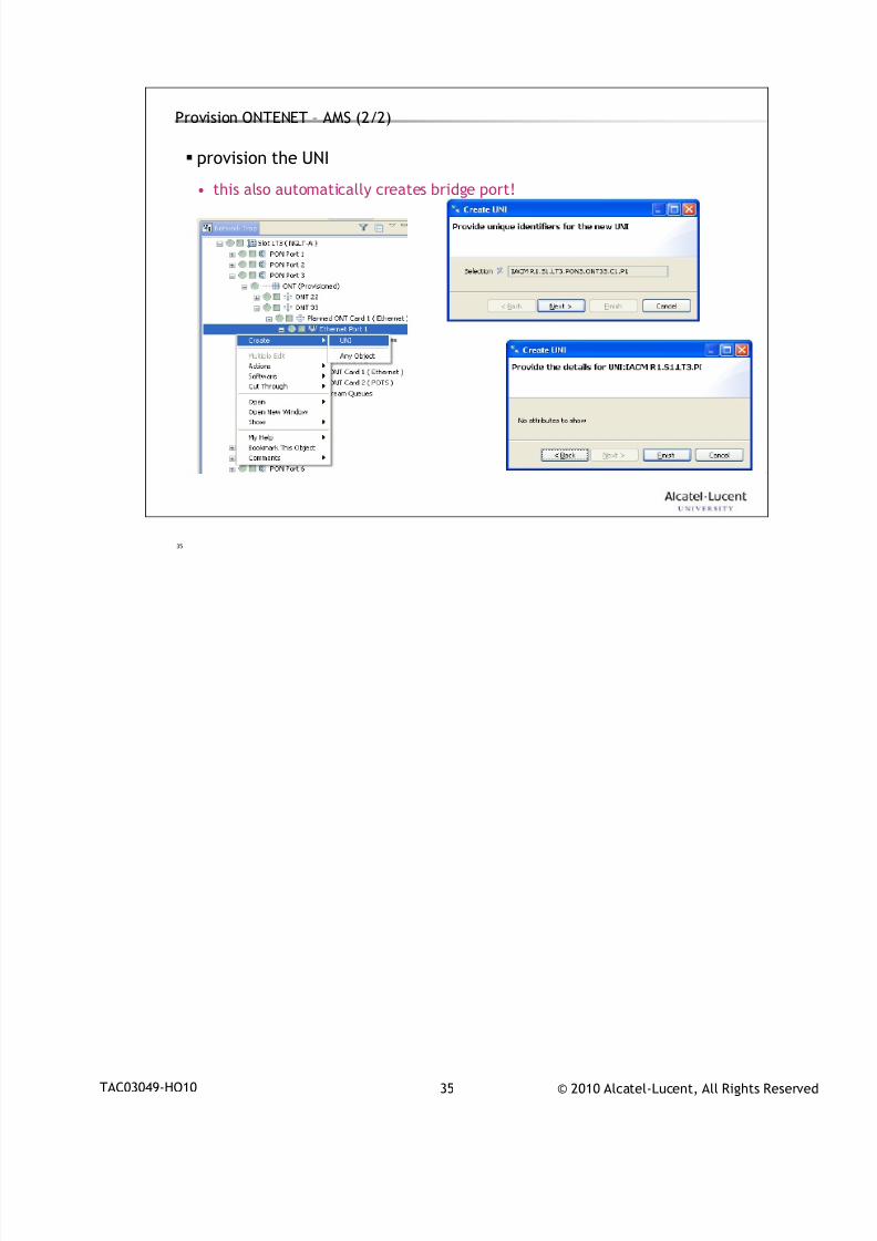
7/18/2019 Alu - A7302 Isam Fttu Operator Gpon Nant-e_ce-PDF
http://slidepdf.com/reader/full/alu-a7302-isam-fttu-operator-gpon-nant-ece-pdf 227/432
© 2010 Alcatel-Lucent, All Rights ReservedTAC03049-HO10 35
35
Provision ONTENET – AMS (2/2)
provision the UNI
• this also automatically creates bridge port!

7/18/2019 Alu - A7302 Isam Fttu Operator Gpon Nant-e_ce-PDF
http://slidepdf.com/reader/full/alu-a7302-isam-fttu-operator-gpon-nant-ece-pdf 228/432
© 2010 Alcatel-Lucent, All Rights ReservedTAC03049-HO10 36
36
Bridge port provisioning5
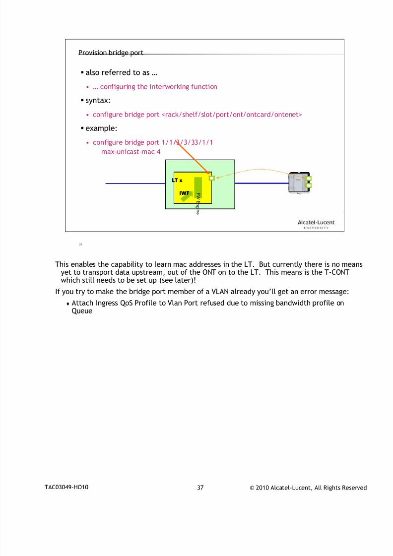
7/18/2019 Alu - A7302 Isam Fttu Operator Gpon Nant-e_ce-PDF
http://slidepdf.com/reader/full/alu-a7302-isam-fttu-operator-gpon-nant-ece-pdf 229/432
© 2010 Alcatel-Lucent, All Rights ReservedTAC03049-HO10 37
37
Provision bridge port
also referred to as …
• … configuring the interworking function syntax:
• configure bridge port <rack/shelf/slot/port/ont/ontcard/ontenet>
example:
• configure bridge port 1/1/3/3/33/1/1
max-unicast-mac 4
LT x
IWF F W
E n gi n e
This enables the capability to learn mac addresses in the LT. But currently there is no means
yet to transport data upstream, out of the ONT on to the LT. This means is the T-CONTwhich still needs to be set up (see later)!
If you try to make the bridge port member of a VLAN already you’ll get an error message:
Attach Ingress QoS Profile to Vlan Port refused due to missing bandwidth profile onQueue
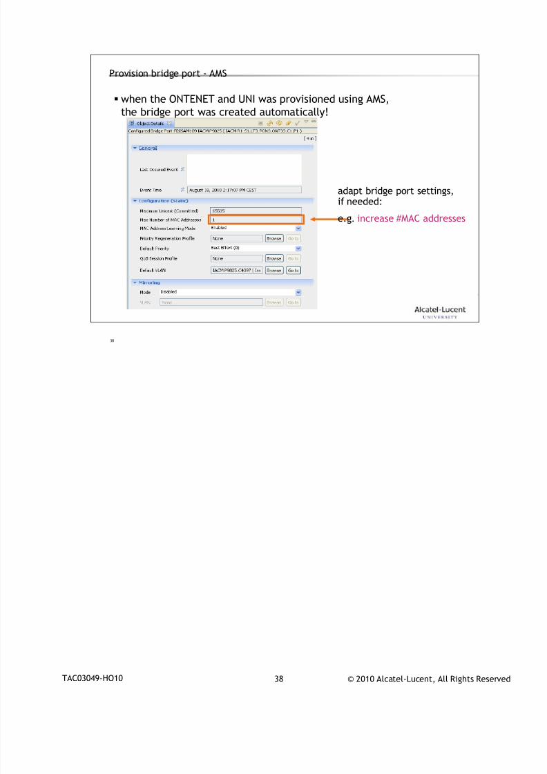
7/18/2019 Alu - A7302 Isam Fttu Operator Gpon Nant-e_ce-PDF
http://slidepdf.com/reader/full/alu-a7302-isam-fttu-operator-gpon-nant-ece-pdf 230/432
© 2010 Alcatel-Lucent, All Rights ReservedTAC03049-HO10 38
38
Provision bridge port - AMS
when the ONTENET and UNI was provisioned using AMS,
the bridge port was created automatically!
adapt bridge port settings,if needed:
e.g. increase #MAC addresses

7/18/2019 Alu - A7302 Isam Fttu Operator Gpon Nant-e_ce-PDF
http://slidepdf.com/reader/full/alu-a7302-isam-fttu-operator-gpon-nant-ece-pdf 231/432
© 2010 Alcatel-Lucent, All Rights ReservedTAC03049-HO10 39
39
www.alcatel-lucent.comwww.alcatel-lucent.com
7/18/2019 Alu - A7302 Isam Fttu Operator Gpon Nant-e_ce-PDF
http://slidepdf.com/reader/full/alu-a7302-isam-fttu-operator-gpon-nant-ece-pdf 232/432
© 2010 Alcatel-Lucent, All Rights ReservedIHUB L2 Forwarding 1
L2 Forwarding with IHUB
During class please switch off your mobile, pager or other that may interrupt.

7/18/2019 Alu - A7302 Isam Fttu Operator Gpon Nant-e_ce-PDF
http://slidepdf.com/reader/full/alu-a7302-isam-fttu-operator-gpon-nant-ece-pdf 233/432
© 2010 Alcatel-Lucent, All Rights ReservedIHUB L2 Forwarding 2
Objective
At the end of this chapter you will be able to:
Give an overview of IHUB concepts
Explain what a VPN service is
Explain what kind of services are supported on the new software
Give an overview of the supported forwarding models

7/18/2019 Alu - A7302 Isam Fttu Operator Gpon Nant-e_ce-PDF
http://slidepdf.com/reader/full/alu-a7302-isam-fttu-operator-gpon-nant-ece-pdf 234/432
© 2010 Alcatel-Lucent, All Rights ReservedIHUB L2 Forwarding 3
3
IHUB basic operation1
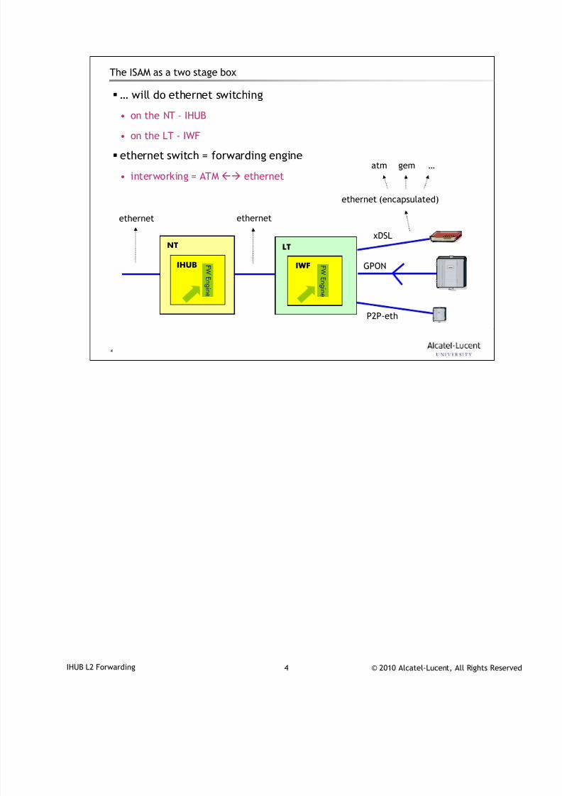
7/18/2019 Alu - A7302 Isam Fttu Operator Gpon Nant-e_ce-PDF
http://slidepdf.com/reader/full/alu-a7302-isam-fttu-operator-gpon-nant-ece-pdf 235/432
© 2010 Alcatel-Lucent, All Rights ReservedIHUB L2 Forwarding 4
4
The ISAM as a two stage box
… will do ethernet switching
• on the NT – IHUB
• on the LT - IWF
ethernet switch = forwarding engine
• interworking = ATM ethernet
LT
IWF F W
E n gi n e
NTxDSL
GPON
P2P-eth
ethernet ethernet
ethernet (encapsulated)
IHUB F W
E n gi n e
atm gem …
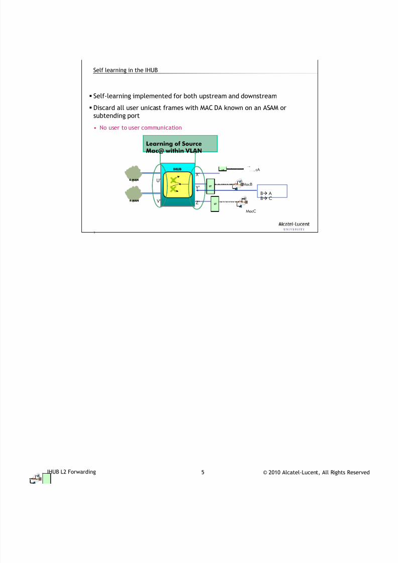
7/18/2019 Alu - A7302 Isam Fttu Operator Gpon Nant-e_ce-PDF
http://slidepdf.com/reader/full/alu-a7302-isam-fttu-operator-gpon-nant-ece-pdf 236/432
© 2010 Alcatel-Lucent, All Rights ReservedIHUB L2 Forwarding 5
5
Self learning in the IHUB
Self-learning implemented for both upstream and downstream
Discard all user unicast frames with MAC DA known on an ASAM or
subtending port
• No user to user communication
Learning of SourceMac@ within VLAN
E-MAN
LT
LT
IHUB
E-MAN
X’
Y’
Z’
MacA
MacB
MacC
U’
V’
B A
B C
LT
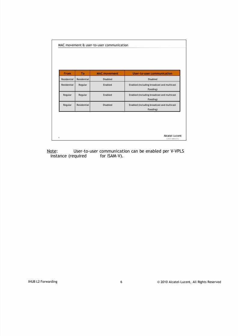
7/18/2019 Alu - A7302 Isam Fttu Operator Gpon Nant-e_ce-PDF
http://slidepdf.com/reader/full/alu-a7302-isam-fttu-operator-gpon-nant-ece-pdf 237/432
© 2010 Alcatel-Lucent, All Rights ReservedIHUB L2 Forwarding 6
6
MAC movement & user-to-user communication
Disabled
Enabled
Enabled
Disabled
MAC movement
Enabled (including broadcast and multicast
flooding)
RegularResidential
Residential
Regular
Residential
To
Enabled (including broadcast and multicast
flooding)
Regular
Enabled (including broadcast and multicast
flooding)
Regular
DisabledResidential
User-to-user communicationFrom
Note: User-to-user communication can be enabled per V-VPLSinstance (required for ISAM-V).

7/18/2019 Alu - A7302 Isam Fttu Operator Gpon Nant-e_ce-PDF
http://slidepdf.com/reader/full/alu-a7302-isam-fttu-operator-gpon-nant-ece-pdf 238/432
© 2010 Alcatel-Lucent, All Rights ReservedIHUB L2 Forwarding 7
7
IHUB L2 forwarding in the overall picture2

7/18/2019 Alu - A7302 Isam Fttu Operator Gpon Nant-e_ce-PDF
http://slidepdf.com/reader/full/alu-a7302-isam-fttu-operator-gpon-nant-ece-pdf 239/432
© 2010 Alcatel-Lucent, All Rights ReservedIHUB L2 Forwarding 8
TAC03002_D_ Ed 01 P07 8 © 2009 Alcatel-Lucent., All rights reserved
8
Supported forwarding models
NANT-D/E NANT-A
VLAN-CC
C-VLAN-CC (Transparent / Protocol aware)
S-VLAN-CC (Transparent)
S+C VLAN-CC (Transparent / Protocol aware)
IPoA CC (Transparent)
Bridging(Enhanced) I-Bridge
PPP Forwarder (PPPoX with MAC@ conc.)
IP Aware Bridge -
IP RoutingOld Model (IP forwarding @ LT) -
New model (E-I-bridge @ LT)
MPLS
VLL -
Simplified VPLS
(S-VPLS = I-bridge with MPLS uplink) -
IPv6
Protocol aware VLAN-CC
(Enhanced) I-Bridge
IP routing -
DR6 R40
DR6 R40
F u t u r e
Single VRMulti VR
Remark : MPLS only supported from R4.1
VLL – Virtual Leased Line
Different forwarding modes are supported in order to make it fit into different network modelsof different operators.
If the DSLAMs are mainly connected to a bridged Metro Ethernet network, the MAC scalabilitymay become an issue when only layer 2 forwarding is done in the DSLAM.In that case the MAC addresses of all end-user terminals will have to be learned in the Metro-Ethernet network, while the MAC tables of bridges are quite limited. In that case, it willprobably be better to use the layer 2+ or L3 forwarding function of the ISAM.
However, if IP routers are used in the Metro Ethernet Network close to the DSLAMs, MACscalability will not be an issue, and layer 2 forwarding in the DSLAM may be an interestingoption, because in general layer 2 means less configuration effort. With 7302 ISAM, operatorshave the flexibility to choose the forwarding mode which best fits in their network.
In general, the previous layer 2 and layer 3 forwarding functions are an overkill for network-VPN services towards business customers, given the number of connections to the same VPNfrom one DSLAM will be mostly only one, or only very few connections per VPN. In suchcases, the VLAN cross-connect mode of the ISAM is much more appropriate for these businessusers:
less configuration effort,
avoid too many bridges or routers in one VPN.

7/18/2019 Alu - A7302 Isam Fttu Operator Gpon Nant-e_ce-PDF
http://slidepdf.com/reader/full/alu-a7302-isam-fttu-operator-gpon-nant-ece-pdf 240/432
© 2010 Alcatel-Lucent, All Rights ReservedIHUB L2 Forwarding 9
9
VLANs on the IHUB (1/2)
VLANs are always emulated by a single v-VPLS, for every forwarding
mode used on the IACM
o For (Unstacked C-VLAN) Intelligent Bridging
o For (Unstacked) C-VLAN Cross Connect
o For (Stacked) S-VLAN Cross Connect
o For the shared S-VLAN part of (Stacked) SC-VLAN Cross Connect
VLANs have only a single ID
• The C-VLAN for Intelligent Bridging or Unstacked Cross-Connect
• The S-VLAN for Stacked Cross Connecto Hence only the outer VLAN tag is specified
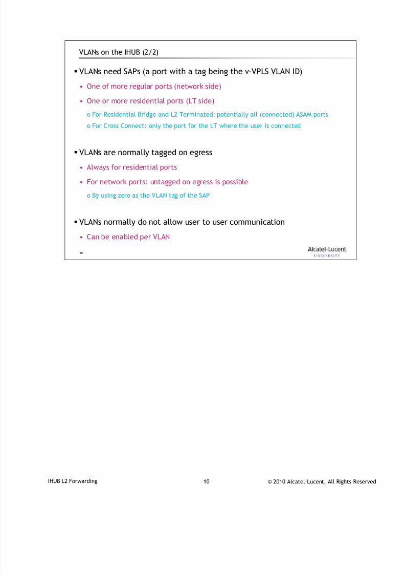
7/18/2019 Alu - A7302 Isam Fttu Operator Gpon Nant-e_ce-PDF
http://slidepdf.com/reader/full/alu-a7302-isam-fttu-operator-gpon-nant-ece-pdf 241/432
© 2010 Alcatel-Lucent, All Rights ReservedIHUB L2 Forwarding 10
10
VLANs on the IHUB (2/2)
VLANs need SAPs (a port with a tag being the v-VPLS VLAN ID)
• One of more regular ports (network side)
• One or more residential ports (LT side)
o For Residential Bridge and L2 Terminated: potentially all (connected) ASAM ports
o For Cross Connect: only the port for the LT where the user is connected
VLANs are normally tagged on egress
• Always for residential ports
• For network ports: untagged on egress is possible
o By using zero as the VLAN tag of the SAP
VLANs normally do not allow user to user communication
• Can be enabled per VLAN
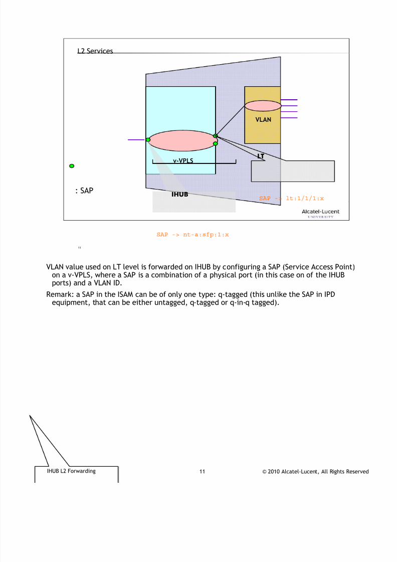
7/18/2019 Alu - A7302 Isam Fttu Operator Gpon Nant-e_ce-PDF
http://slidepdf.com/reader/full/alu-a7302-isam-fttu-operator-gpon-nant-ece-pdf 242/432
© 2010 Alcatel-Lucent, All Rights ReservedIHUB L2 Forwarding 11
11
L2 Services
: SAP
VLAN
v-VPLS
IHUB
LT
SAP -> lt:1/1/1:x
SAP -> nt-a:sfp:1:x
VLAN value used on LT level is forwarded on IHUB by configuring a SAP (Service Access Point)
on a v-VPLS, where a SAP is a combination of a physical port (in this case on of the IHUBports) and a VLAN ID.
Remark: a SAP in the ISAM can be of only one type: q-tagged (this unlike the SAP in IPDequipment, that can be either untagged, q-tagged or q-in-q tagged).

7/18/2019 Alu - A7302 Isam Fttu Operator Gpon Nant-e_ce-PDF
http://slidepdf.com/reader/full/alu-a7302-isam-fttu-operator-gpon-nant-ece-pdf 243/432
© 2010 Alcatel-Lucent, All Rights ReservedIHUB L2 Forwarding 12
12
Configuration of IHUB VLAN via AMS3
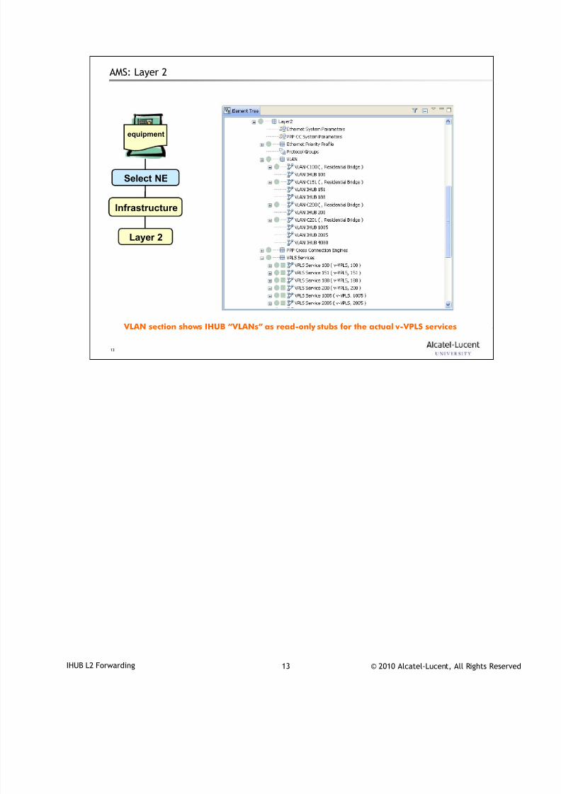
7/18/2019 Alu - A7302 Isam Fttu Operator Gpon Nant-e_ce-PDF
http://slidepdf.com/reader/full/alu-a7302-isam-fttu-operator-gpon-nant-ece-pdf 244/432
© 2010 Alcatel-Lucent, All Rights ReservedIHUB L2 Forwarding 13
13
AMS: Layer 2
equipment
Select NE
Infrastructure
Layer 2
VLAN section shows IHUB “VLANs” as read-only stubs for the actual v-VPLS services
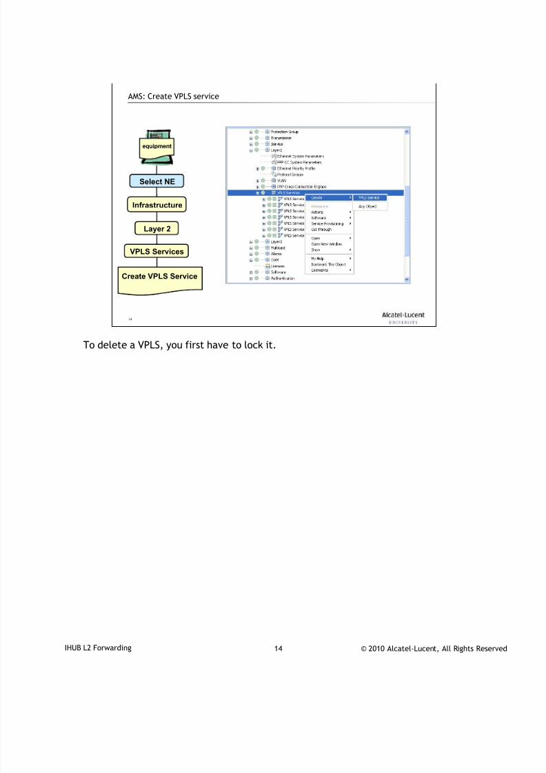
7/18/2019 Alu - A7302 Isam Fttu Operator Gpon Nant-e_ce-PDF
http://slidepdf.com/reader/full/alu-a7302-isam-fttu-operator-gpon-nant-ece-pdf 245/432
© 2010 Alcatel-Lucent, All Rights ReservedIHUB L2 Forwarding 14
14
AMS: Create VPLS service
equipment
Select NE
Infrastructure
Layer 2
Create VPLS Service
VPLS Services
To delete a VPLS, you first have to lock it.
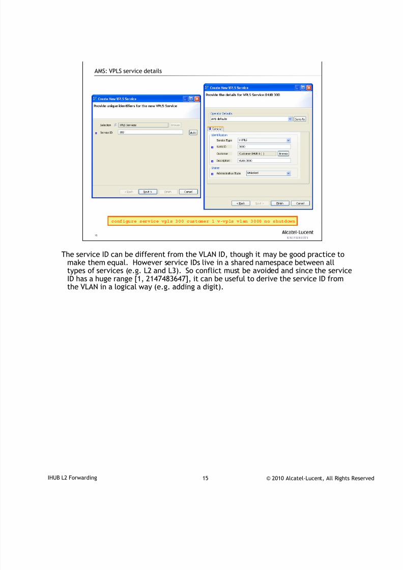
7/18/2019 Alu - A7302 Isam Fttu Operator Gpon Nant-e_ce-PDF
http://slidepdf.com/reader/full/alu-a7302-isam-fttu-operator-gpon-nant-ece-pdf 246/432
© 2010 Alcatel-Lucent, All Rights ReservedIHUB L2 Forwarding 15
15
AMS: VPLS service details
configure service vpls 300 customer 1 v-vpls vlan 3000 no shutdown
The service ID can be different from the VLAN ID, though it may be good practice tomake them equal. However service IDs live in a shared namespace between alltypes of services (e.g. L2 and L3). So conflict must be avoided and since the service
ID has a huge range [1, 2147483647], it can be useful to derive the service ID fromthe VLAN in a logical way (e.g. adding a digit).
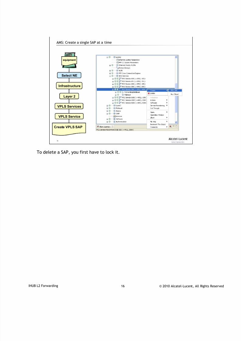
7/18/2019 Alu - A7302 Isam Fttu Operator Gpon Nant-e_ce-PDF
http://slidepdf.com/reader/full/alu-a7302-isam-fttu-operator-gpon-nant-ece-pdf 247/432
© 2010 Alcatel-Lucent, All Rights ReservedIHUB L2 Forwarding 16
16
AMS: Create a single SAP at a time
equipment
Select NE
Infrastructure
Layer 2
VPLS Services
VPLS Service
Create VPLS SAP
To delete a SAP, you first have to lock it.
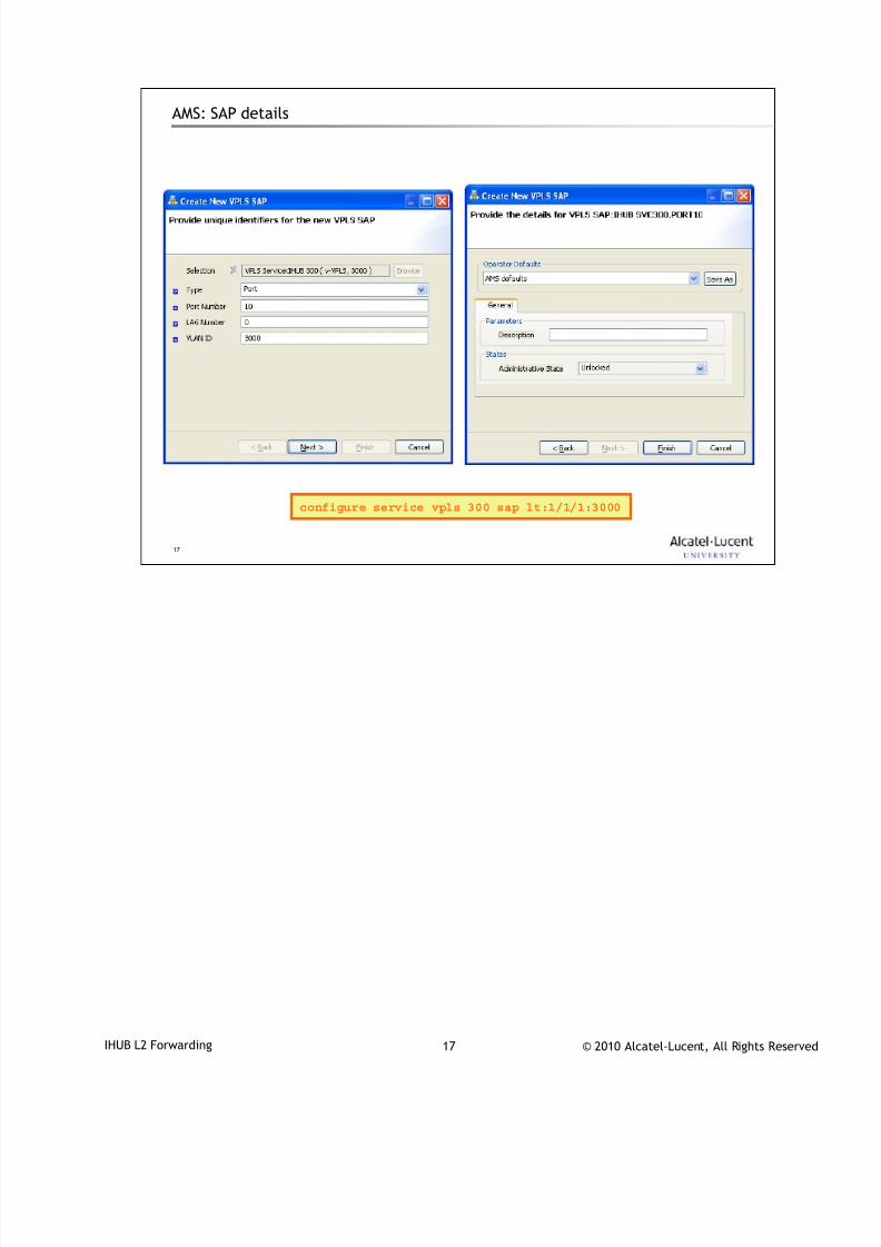
7/18/2019 Alu - A7302 Isam Fttu Operator Gpon Nant-e_ce-PDF
http://slidepdf.com/reader/full/alu-a7302-isam-fttu-operator-gpon-nant-ece-pdf 248/432
© 2010 Alcatel-Lucent, All Rights ReservedIHUB L2 Forwarding 17
17
AMS: SAP details
configure service vpls 300 sap lt:1/1/1:3000
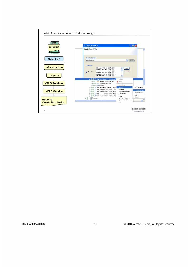
7/18/2019 Alu - A7302 Isam Fttu Operator Gpon Nant-e_ce-PDF
http://slidepdf.com/reader/full/alu-a7302-isam-fttu-operator-gpon-nant-ece-pdf 249/432
© 2010 Alcatel-Lucent, All Rights ReservedIHUB L2 Forwarding 18
18
AMS: Create a number of SAPs in one go
equipment
Select NE
Infrastructure
Layer 2
VPLS Services
VPLS Service
Actions:Create Port SAPs
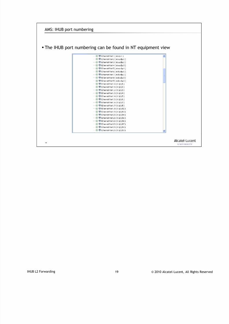
7/18/2019 Alu - A7302 Isam Fttu Operator Gpon Nant-e_ce-PDF
http://slidepdf.com/reader/full/alu-a7302-isam-fttu-operator-gpon-nant-ece-pdf 250/432
© 2010 Alcatel-Lucent, All Rights ReservedIHUB L2 Forwarding 19
19
AMS: IHUB port numbering
The IHUB port numbering can be found in NT equipment view

7/18/2019 Alu - A7302 Isam Fttu Operator Gpon Nant-e_ce-PDF
http://slidepdf.com/reader/full/alu-a7302-isam-fttu-operator-gpon-nant-ece-pdf 251/432
© 2010 Alcatel-Lucent, All Rights ReservedIHUB L2 Forwarding 20
20
Configuration of IHUB VLAN via CLI4
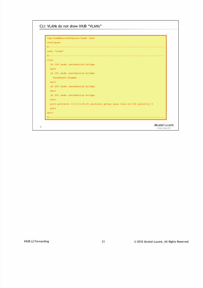
7/18/2019 Alu - A7302 Isam Fttu Operator Gpon Nant-e_ce-PDF
http://slidepdf.com/reader/full/alu-a7302-isam-fttu-operator-gpon-nant-ece-pdf 252/432
© 2010 Alcatel-Lucent, All Rights ReservedIHUB L2 Forwarding 21
21
CLI: VLANs do not show IHUB “VLANs”
leg:isadmin>configure>vlan# info
configure
#-------------------------------------------------------------------------------
echo "vlan"
#-------------------------------------------------------------------------------
vlan
id 100 mode residential-bridge
exit
id 151 mode residential-bridge
broadcast-frames
exit
id 200 mode residential-bridge
exit
id 201 mode residential-bridge
exit
port-protocol 1/1/1/1:8:35 protocol-group ipoe vlan-id 150 priority 0
exit
exit
#-------------------------------------------------------------------------------
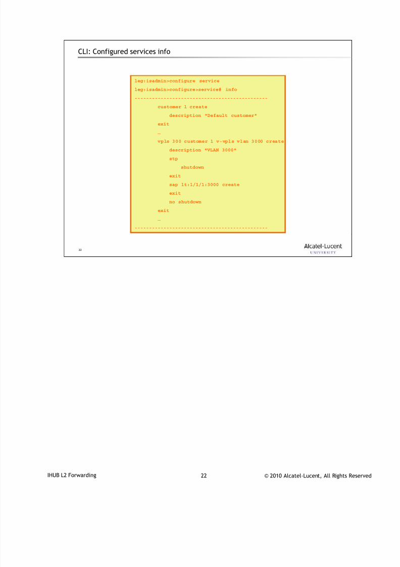
7/18/2019 Alu - A7302 Isam Fttu Operator Gpon Nant-e_ce-PDF
http://slidepdf.com/reader/full/alu-a7302-isam-fttu-operator-gpon-nant-ece-pdf 253/432
© 2010 Alcatel-Lucent, All Rights ReservedIHUB L2 Forwarding 22
22
CLI: Configured services info
leg:isadmin>configure service
leg:isadmin>configure>service# info
----------------------------------------------
customer 1 create
description "Default customer"
exit
…
vpls 300 customer 1 v-vpls vlan 3000 create
description "VLAN 3000"
stp
shutdown
exit
sap lt:1/1/1:3000 create
exit
no shutdown
exit
…
----------------------------------------------
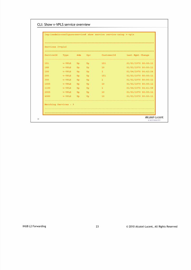
7/18/2019 Alu - A7302 Isam Fttu Operator Gpon Nant-e_ce-PDF
http://slidepdf.com/reader/full/alu-a7302-isam-fttu-operator-gpon-nant-ece-pdf 254/432
© 2010 Alcatel-Lucent, All Rights ReservedIHUB L2 Forwarding 23
23
CLI: Show v-VPLS service overview
leg:isadmin>configure>service# show service service-using v-vpls
===============================================================================
Services [vvpls]
===============================================================================
ServiceId Type Adm Opr CustomerId Last Mgmt Change
-------------------------------------------------------------------------------
151 v-VPLS Up Up 151 01/01/1970 00:00:11
188 v-VPLS Up Up 10 01/01/1970 00:00:11
190 v-VPLS Up Up 1 01/04/1970 04:42:24
200 v-VPLS Up Up 151 01/01/1970 00:00:11
300 v-VPLS Up Up 1 01/01/1970 00:00:11
1005 v-VPLS Up Up 10 01/01/1970 00:00:11
1190 v-VPLS Up Up 1 01/04/1970 04:41:58
2005 v-VPLS Up Up 10 01/01/1970 00:00:11
4080 v-VPLS Up Up 10 01/01/1970 00:00:11
-------------------------------------------------------------------------------
Matching Services : 9
-------------------------------------------------------------------------------
===============================================================================
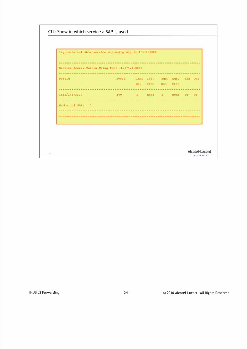
7/18/2019 Alu - A7302 Isam Fttu Operator Gpon Nant-e_ce-PDF
http://slidepdf.com/reader/full/alu-a7302-isam-fttu-operator-gpon-nant-ece-pdf 255/432
© 2010 Alcatel-Lucent, All Rights ReservedIHUB L2 Forwarding 24
24
CLI: Show in which service a SAP is used
leg:isadmin># show service sap-using sap lt:1/1/1:3000
===============================================================================
Service Access Points Using Port lt:1/1/1:3000
===============================================================================
PortId SvcId Ing. Ing. Egr. Egr. Adm Opr
QoS Fltr QoS Fltr
-------------------------------------------------------------------------------
lt:1/1/1:3000 300 1 none 1 none Up Up
-------------------------------------------------------------------------------
Number of SAPs : 1
-------------------------------------------------------------------------------
===============================================================================
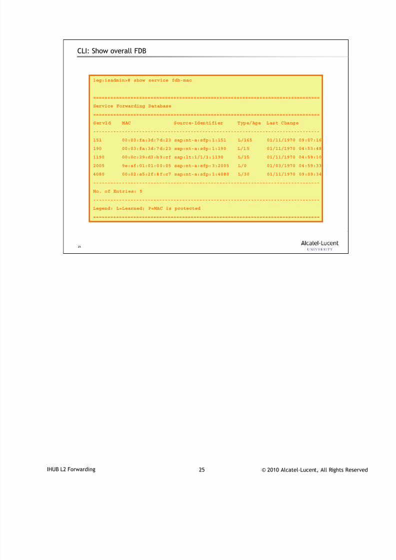
7/18/2019 Alu - A7302 Isam Fttu Operator Gpon Nant-e_ce-PDF
http://slidepdf.com/reader/full/alu-a7302-isam-fttu-operator-gpon-nant-ece-pdf 256/432
© 2010 Alcatel-Lucent, All Rights ReservedIHUB L2 Forwarding 25
25
CLI: Show overall FDB
leg:isadmin># show service fdb-mac
===============================================================================
Service Forwarding Database
===============================================================================
ServId MAC Source-Identifier Type/Age Last Change
-------------------------------------------------------------------------------
151 00:03:fa:3d:7d:23 sap:nt-a:sfp:1:151 L/165 01/11/1970 09:07:16
190 00:03:fa:3d:7d:23 sap:nt-a:sfp:1:190 L/15 01/11/1970 04:53:48
1190 00:0c:29:d3:b9:cf sap:lt:1/1/1:1190 L/15 01/11/1970 04:59:10
2005 9e:af:01:01:00:05 sap:nt-a:sfp:3:2005 L/0 01/03/1970 04:59:33
4080 00:02:a5:2f:8f:c7 sap:nt-a:sfp:1:4080 L/30 01/11/1970 09:09:34
-------------------------------------------------------------------------------
No. of Entries: 5
-------------------------------------------------------------------------------
Legend: L=Learned; P=MAC is protected
===============================================================================

7/18/2019 Alu - A7302 Isam Fttu Operator Gpon Nant-e_ce-PDF
http://slidepdf.com/reader/full/alu-a7302-isam-fttu-operator-gpon-nant-ece-pdf 257/432
© 2010 Alcatel-Lucent, All Rights ReservedIHUB L2 Forwarding 26
26
CLI: Show per service FDB
leg:isadmin># show service id 4080 fdb detail
===============================================================================
Forwarding Database, Service 4080
===============================================================================
ServId MAC Source-Identifier Type/Age Last Change
-------------------------------------------------------------------------------
4080 00:02:a5:67:92:42 sap:nt-a:sfp:1:4080 L/30 11/10/2010 14:37:40
4080 00:03:ba:05:f1:91 sap:nt-a:sfp:1:4080 L/105 11/14/2010 20:48:44
4080 78:e7:d1:be:b4:a0 sap:nt-a:sfp:1:4080 L/45 11/14/2010 12:24:47
4080 78:e7:d1:be:b4:e4 sap:nt-a:sfp:1:4080 L/285 11/14/2010 20:57:54
4080 9e:ae:01:01:00:02 sap:nt-a:sfp:1:4080 L/0 11/10/2010 14:37:40
-------------------------------------------------------------------------------
No. of MAC Entries: 5
-------------------------------------------------------------------------------
Legend: L=Learned; P=MAC is protected
===============================================================================

7/18/2019 Alu - A7302 Isam Fttu Operator Gpon Nant-e_ce-PDF
http://slidepdf.com/reader/full/alu-a7302-isam-fttu-operator-gpon-nant-ece-pdf 258/432
© 2010 Alcatel-Lucent, All Rights ReservedIHUB L2 Forwarding 27
27
www.alcatel-lucent.comwww.alcatel-lucent.com

7/18/2019 Alu - A7302 Isam Fttu Operator Gpon Nant-e_ce-PDF
http://slidepdf.com/reader/full/alu-a7302-isam-fttu-operator-gpon-nant-ece-pdf 259/432
© 2010 Alcatel-Lucent, All Rights ReservedDocument Number | Document Title 1
Intelligent Bridging on IACM
During class please switch off your mobile, pager or other that may interrupt.

7/18/2019 Alu - A7302 Isam Fttu Operator Gpon Nant-e_ce-PDF
http://slidepdf.com/reader/full/alu-a7302-isam-fttu-operator-gpon-nant-ece-pdf 260/432
© 2010 Alcatel-Lucent, All Rights ReservedDocument Number | Document Title 2
Objective
After attending this session, you should be able to:
• Describe what a Residential Bridge VLAN (= Intelligent Bridge VLAN) is
• Explain how the RB-VLAN is behaving on LT
• Create a RB-VLAN via AMS and CLI on IACM
• Associate a RB-VLAN to a bridge port with or without VLAN translation

7/18/2019 Alu - A7302 Isam Fttu Operator Gpon Nant-e_ce-PDF
http://slidepdf.com/reader/full/alu-a7302-isam-fttu-operator-gpon-nant-ece-pdf 261/432
© 2010 Alcatel-Lucent, All Rights ReservedDocument Number | Document Title 3
3
Intelligent Bridging
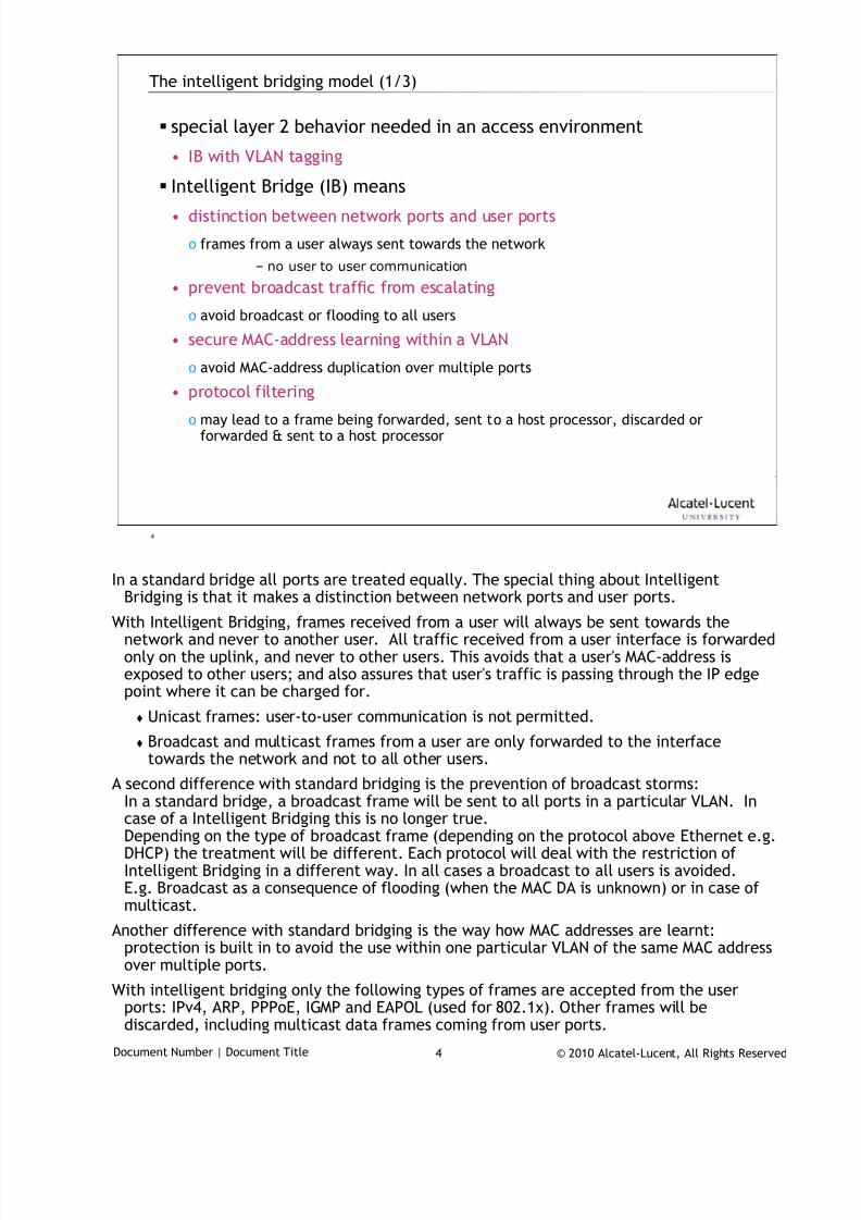
7/18/2019 Alu - A7302 Isam Fttu Operator Gpon Nant-e_ce-PDF
http://slidepdf.com/reader/full/alu-a7302-isam-fttu-operator-gpon-nant-ece-pdf 262/432
© 2010 Alcatel-Lucent, All Rights ReservedDocument Number | Document Title 4
4
The intelligent bridging model (1/3)
special layer 2 behavior needed in an access environment
• IB with VLAN tagging
Intelligent Bridge (IB) means
• distinction between network ports and user ports
o frames from a user always sent towards the network
– no user to user communication
• prevent broadcast traffic from escalating
o avoid broadcast or flooding to all users
• secure MAC-address learning within a VLAN
o avoid MAC-address duplication over multiple ports
• protocol filteringo may lead to a frame being forwarded, sent to a host processor, discarded or
forwarded & sent to a host processor
In a standard bridge all ports are treated equally. The special thing about Intelligent
Bridging is that it makes a distinction between network ports and user ports.
With Intelligent Bridging, frames received from a user will always be sent towards thenetwork and never to another user. All traffic received from a user interface is forwardedonly on the uplink, and never to other users. This avoids that a user's MAC-address isexposed to other users; and also assures that user's traffic is passing through the IP edgepoint where it can be charged for.
Unicast frames: user-to-user communication is not permitted.
Broadcast and multicast frames from a user are only forwarded to the interfacetowards the network and not to all other users.
A second difference with standard bridging is the prevention of broadcast storms:In a standard bridge, a broadcast frame will be sent to all ports in a particular VLAN. Incase of a Intelligent Bridging this is no longer true.Depending on the type of broadcast frame (depending on the protocol above Ethernet e.g.DHCP) the treatment will be different. Each protocol will deal with the restriction ofIntelligent Bridging in a different way. In all cases a broadcast to all users is avoided.E.g. Broadcast as a consequence of flooding (when the MAC DA is unknown) or in case ofmulticast.
Another difference with standard bridging is the way how MAC addresses are learnt:protection is built in to avoid the use within one particular VLAN of the same MAC addressover multiple ports.
With intelligent bridging only the following types of frames are accepted from the userports: IPv4, ARP, PPPoE, IGMP and EAPOL (used for 802.1x). Other frames will bediscarded, including multicast data frames coming from user ports.
7/18/2019 Alu - A7302 Isam Fttu Operator Gpon Nant-e_ce-PDF
http://slidepdf.com/reader/full/alu-a7302-isam-fttu-operator-gpon-nant-ece-pdf 263/432
© 2010 Alcatel-Lucent, All Rights ReservedDocument Number | Document Title 5
5
The intelligent bridging model (2/3)
multiple users connected to 1 VLAN ID
why VLAN translation (customer vlan to network vlan)
• wholesale per service
o Drivers: VDSL and Eth offer more BW, so it makes sense to wholesale this “in
pieces” rather than the complete DSL line as a whole
o Consequences: Model with VLANs on DSL line; behaviour equivalent to multi-VC
model on ATM/ADSL
• VLAN per service and per provider in the aggregation network
o Service provider is free to choose CPE configuration, but VLANs in aggregation
network are under control of ILEC
• ultimately 1 subscriber (1 line) may have to support 2 HSIA services or 2
video services from different service providers
There are many operators who base their network architecture on one PVC per service when
connecting ADSL subscribers. Once those operators start deploying VDSL, they areimmediately confronted with the issue, that their is no similar approach for EFMinterfaces. That’s why we have introduced VLAN Translation.
Requirement is driven by the wholesale model. Operators wants to use a network modelwhereby a given user can be subscribed to a different service provider for each service.Therefore they want to have separate "circuits" per service all the way up to the CPE.They are looking at a model of VLAN/service on the DSL line, and VLAN/service/ISP in theaggregation network.
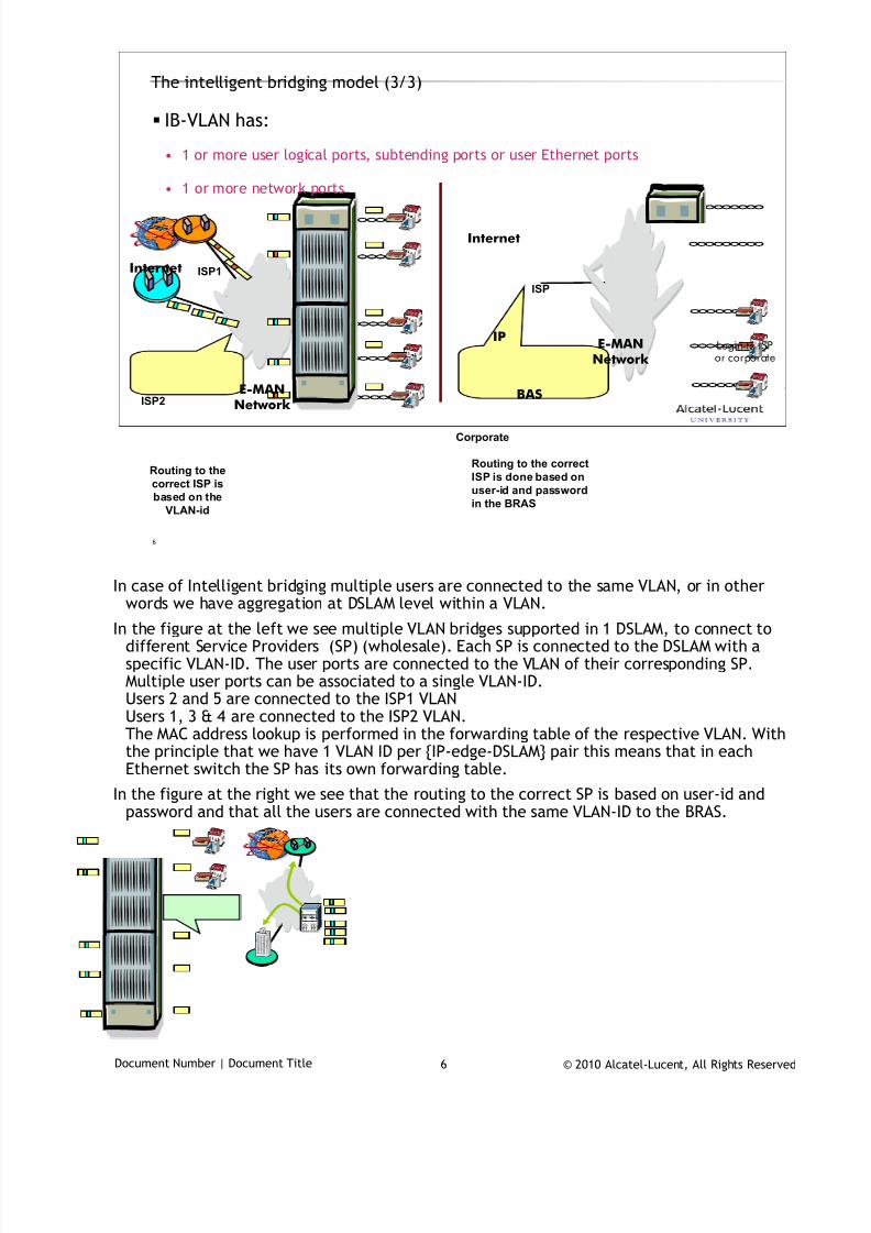
7/18/2019 Alu - A7302 Isam Fttu Operator Gpon Nant-e_ce-PDF
http://slidepdf.com/reader/full/alu-a7302-isam-fttu-operator-gpon-nant-ece-pdf 264/432
© 2010 Alcatel-Lucent, All Rights ReservedDocument Number | Document Title 6
6
The intelligent bridging model (3/3)
IB-VLAN has:
• 1 or more user logical ports, subtending ports or user Ethernet ports
• 1 or more network ports
Internet
E-MAN
Network ISP2
ISP1
Routing to the
correct ISP is
based on the
VLAN-id
Routing to the correct
ISP is done based on
user-id and password
in the BRAS
E-MANNetwork
IP
Internet
ISP
Corporate
BAS
Login to ISPor corporate
In case of Intelligent bridging multiple users are connected to the same VLAN, or in other
words we have aggregation at DSLAM level within a VLAN.
In the figure at the left we see multiple VLAN bridges supported in 1 DSLAM, to connect todifferent Service Providers (SP) (wholesale). Each SP is connected to the DSLAM with aspecific VLAN-ID. The user ports are connected to the VLAN of their corresponding SP.Multiple user ports can be associated to a single VLAN-ID.Users 2 and 5 are connected to the ISP1 VLANUsers 1, 3 & 4 are connected to the ISP2 VLAN.The MAC address lookup is performed in the forwarding table of the respective VLAN. Withthe principle that we have 1 VLAN ID per {IP-edge-DSLAM} pair this means that in eachEthernet switch the SP has its own forwarding table.
In the figure at the right we see that the routing to the correct SP is based on user-id andpassword and that all the users are connected with the same VLAN-ID to the BRAS.
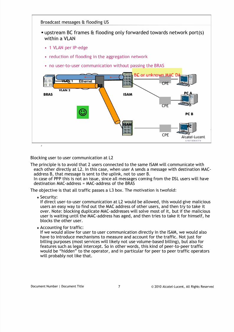
7/18/2019 Alu - A7302 Isam Fttu Operator Gpon Nant-e_ce-PDF
http://slidepdf.com/reader/full/alu-a7302-isam-fttu-operator-gpon-nant-ece-pdf 265/432
© 2010 Alcatel-Lucent, All Rights ReservedDocument Number | Document Title 7
7
Broadcast messages & flooding US
upstream BC frames & flooding only forwarded towards network port(s)
within a VLAN
• 1 VLAN per IP-edge
• reduction of flooding in the aggregation network
• no user-to-user communication without passing the BRAS
th rn t
BRAS PC A ISAM
PCISAM
PC B
BC or unknown MAC DA
BR
VLAN 1
VLAN 2
CPE
CPE
CPE
Blocking user to user communication at L2
The principle is to avoid that 2 users connected to the same ISAM will communicate witheach other directly at L2. In this case, when user A sends a message with destination MAC-address B, that message is sent to the uplink, not to user B.In case of PPP this is not an issue, since all messages coming from the DSL users will havedestination MAC-address = MAC-address of the BRAS
The objective is that all traffic passes a L3 box. The motivation is twofold:
Security:If direct user-to-user communication at L2 would be allowed, this would give malicioususers an easy way to find out the MAC address of other users, and then try to take itover. Note: blocking duplicate MAC-addresses will solve most of it, but if the malicious
user is waiting until the MAC-address has aged, and then tries to take it for himself, heblocks the other user.
Accounting for traffic:If we would allow for user to user communication directly in the ISAM, we would alsohave to introduce mechanisms to measure and account for the traffic. Not just forbilling purposes (most services will likely not use volume-based billing), but also forfeatures such as legal intercept. So in other words, this kind of peer-to-peer trafficwould be “hidden” to the operator, and in particular for peer to peer traffic operatorswill probably not like that.
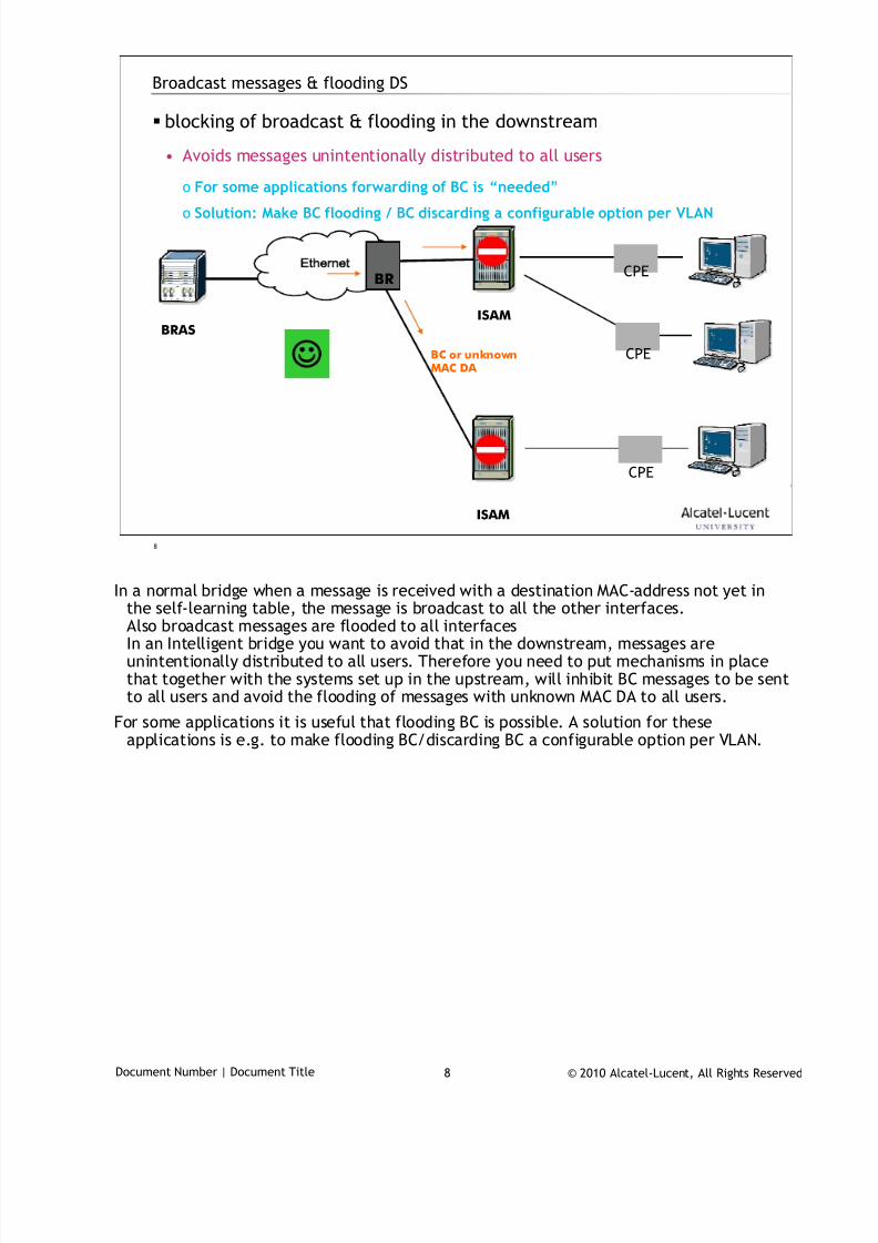
7/18/2019 Alu - A7302 Isam Fttu Operator Gpon Nant-e_ce-PDF
http://slidepdf.com/reader/full/alu-a7302-isam-fttu-operator-gpon-nant-ece-pdf 266/432
© 2010 Alcatel-Lucent, All Rights ReservedDocument Number | Document Title 8
8
Broadcast messages & flooding DS
blocking of broadcast & flooding in the downstream
• Avoids messages unintentionally distributed to all users
o For some applications forwarding of BC is “needed”
o Solution: Make BC flooding / BC discarding a configurable option per VLAN
ISAM
th rn t
BRASISAM
BC or unknownMAC DA
BR
CPE
CPE
CPE
In a normal bridge when a message is received with a destination MAC-address not yet in
the self-learning table, the message is broadcast to all the other interfaces.Also broadcast messages are flooded to all interfacesIn an Intelligent bridge you want to avoid that in the downstream, messages areunintentionally distributed to all users. Therefore you need to put mechanisms in placethat together with the systems set up in the upstream, will inhibit BC messages to be sentto all users and avoid the flooding of messages with unknown MAC DA to all users.
For some applications it is useful that flooding BC is possible. A solution for theseapplications is e.g. to make flooding BC/discarding BC a configurable option per VLAN.
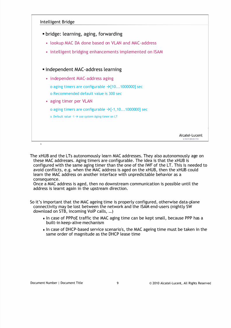
7/18/2019 Alu - A7302 Isam Fttu Operator Gpon Nant-e_ce-PDF
http://slidepdf.com/reader/full/alu-a7302-isam-fttu-operator-gpon-nant-ece-pdf 267/432
© 2010 Alcatel-Lucent, All Rights ReservedDocument Number | Document Title 9
9
Intelligent Bridge
bridge: learning, aging, forwarding
• lookup MAC DA done based on VLAN and MAC-address
• intelligent bridging enhancements implemented on ISAM
independent MAC-address learning
• independent MAC-address aging
o aging timers are configurable [10...1000000] sec
o Recommended default value is 300 sec
• aging timer per VLAN
o aging timers are configurable [-1,10...1000000] sec
o Default value –1 use system Aging timer on LT
The xHUB and the LTs autonomously learn MAC addresses. They also autonomously age on
these MAC addresses. Aging timers are configurable. The idea is that the xHUB isconfigured with the same aging timer than the one of the IWF of the LT. This is needed toavoid conflicts, e.g. when the MAC address is aged on the xHUB, then the xHUB couldlearn the MAC address on another interface with unpredictable behavior as aconsequence.Once a MAC address is aged, then no downstream communication is possible until theaddress is learnt again in the upstream direction.
So it’s important that the MAC ageing time is properly configured, otherwise data-planeconnectivity may be lost between the network and the ISAM end-users (nightly SW
download on STB, incoming VoIP calls, …) In case of PPPoE traffic the MAC aging time can be kept small, because PPP has a
built-in keep-alive mechanism
In case of DHCP-based service scenario's, the MAC ageing time must be taken in thesame order of magnitude as the DHCP lease time
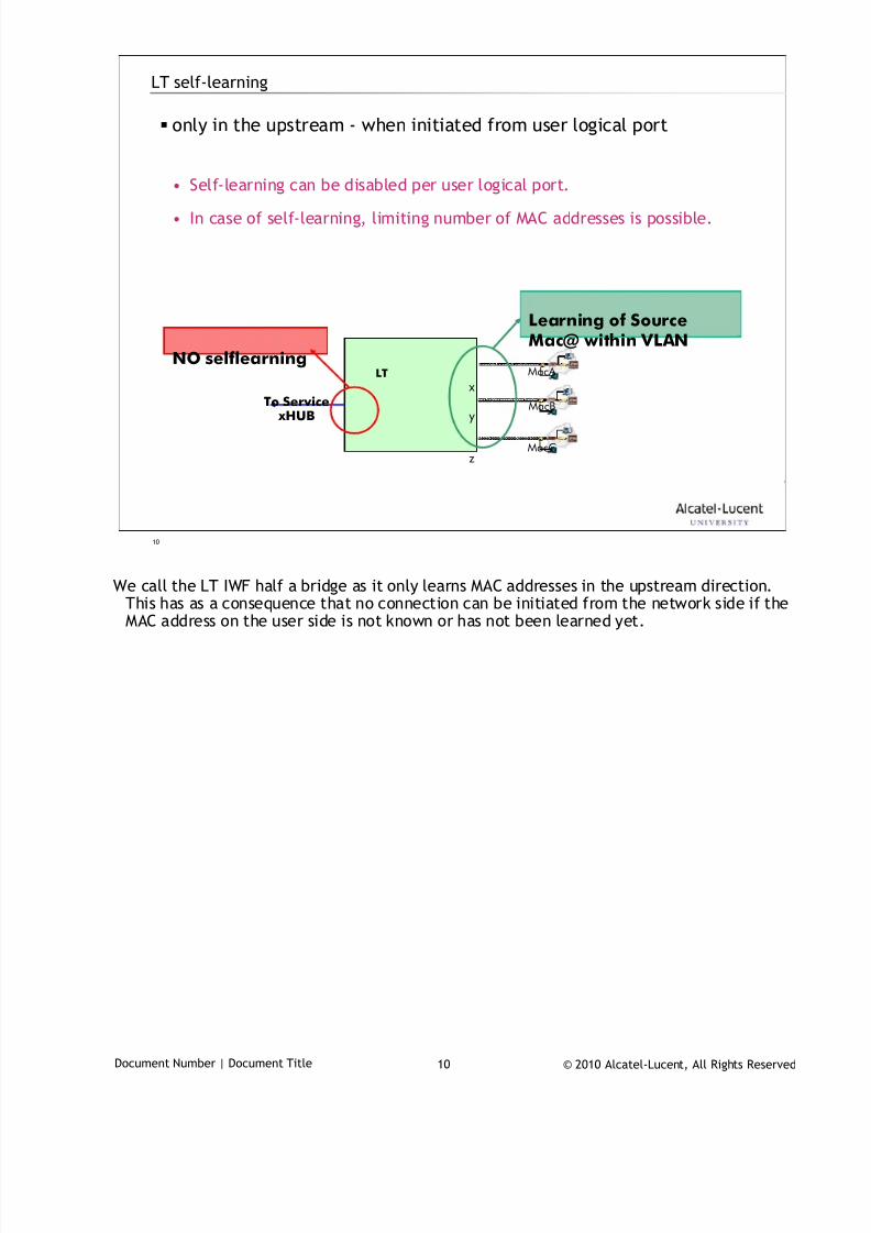
7/18/2019 Alu - A7302 Isam Fttu Operator Gpon Nant-e_ce-PDF
http://slidepdf.com/reader/full/alu-a7302-isam-fttu-operator-gpon-nant-ece-pdf 268/432
© 2010 Alcatel-Lucent, All Rights ReservedDocument Number | Document Title 10
10
LT self-learning
only in the upstream - when initiated from user logical port
• Self-learning can be disabled per user logical port.
• In case of self-learning, limiting number of MAC addresses is possible.
LT
To Service xHUB
Learning of SourceMac@ within VLAN
NO selflearning
x
y
z
MacA
MacB
MacC
We call the LT IWF half a bridge as it only learns MAC addresses in the upstream direction.
This has as a consequence that no connection can be initiated from the network side if theMAC address on the user side is not known or has not been learned yet.
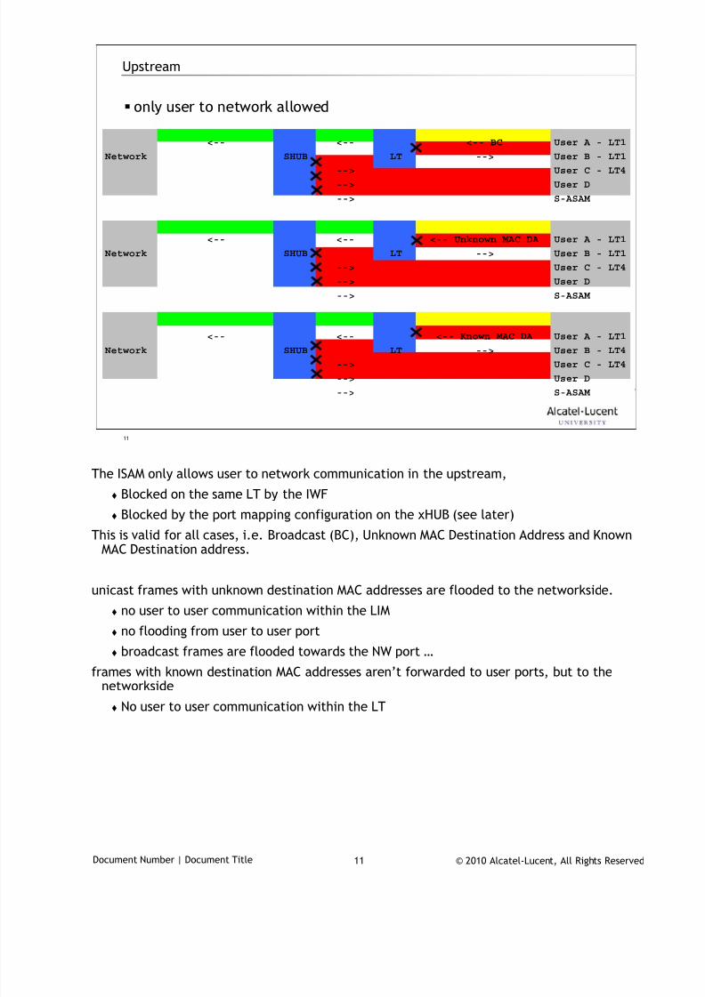
7/18/2019 Alu - A7302 Isam Fttu Operator Gpon Nant-e_ce-PDF
http://slidepdf.com/reader/full/alu-a7302-isam-fttu-operator-gpon-nant-ece-pdf 269/432
© 2010 Alcatel-Lucent, All Rights ReservedDocument Number | Document Title 11
11
Upstream
only user to network allowed
<-- <-- <-- BC User A - LT1
Network SHUB LT --> User B - LT1
--> User C - LT4
--> User D
--> S-ASAM
<-- <-- <-- Unknown MAC DA User A - LT1
Network SHUB LT --> User B - LT1
--> User C - LT4
--> User D
--> S-ASAM
<-- <-- <-- Known MAC DA User A - LT1
Network SHUB LT --> User B - LT4
--> User C - LT4
--> User D
--> S-ASAM
The ISAM only allows user to network communication in the upstream,
Blocked on the same LT by the IWF
Blocked by the port mapping configuration on the xHUB (see later)
This is valid for all cases, i.e. Broadcast (BC), Unknown MAC Destination Address and KnownMAC Destination address.
unicast frames with unknown destination MAC addresses are flooded to the networkside.
no user to user communication within the LIM
no flooding from user to user port
broadcast frames are flooded towards the NW port …
frames with known destination MAC addresses aren’t forwarded to user ports, but to thenetworkside
No user to user communication within the LT
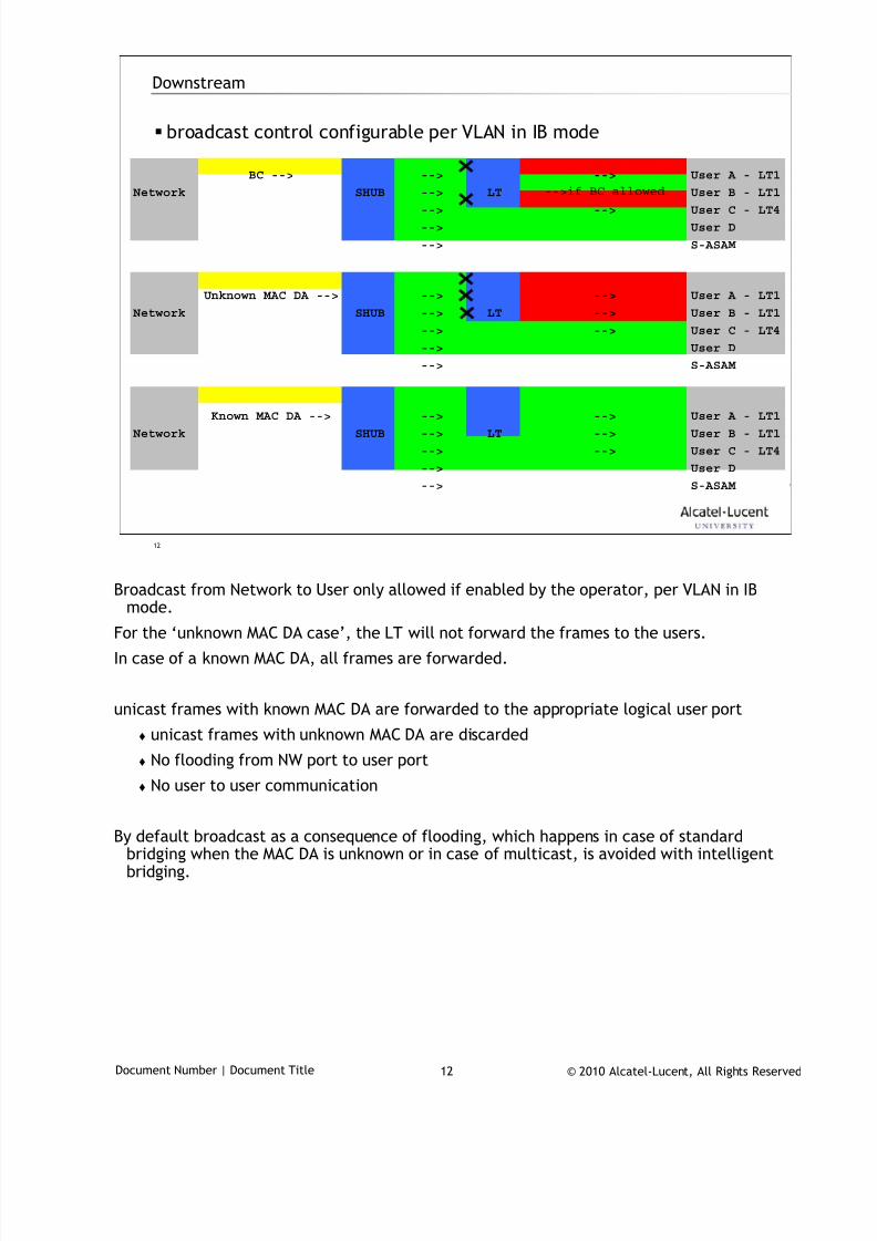
7/18/2019 Alu - A7302 Isam Fttu Operator Gpon Nant-e_ce-PDF
http://slidepdf.com/reader/full/alu-a7302-isam-fttu-operator-gpon-nant-ece-pdf 270/432
© 2010 Alcatel-Lucent, All Rights ReservedDocument Number | Document Title 12
12
Downstream
broadcast control configurable per VLAN in IB mode
BC --> --> --> User A - LT1
Network SHUB --> LT -->if BC allowed User B - LT1
--> --> User C - LT4
--> User D
--> S-ASAM
Unknown MAC DA --> --> --> User A - LT1
Network SHUB --> LT --> User B - LT1
--> --> User C - LT4
--> User D
--> S-ASAM
Known MAC DA --> --> --> User A - LT1
Network SHUB --> LT --> User B - LT1
--> --> User C - LT4
--> User D
--> S-ASAM
Broadcast from Network to User only allowed if enabled by the operator, per VLAN in IB
mode.
For the ‘unknown MAC DA case’, the LT will not forward the frames to the users.
In case of a known MAC DA, all frames are forwarded.
unicast frames with known MAC DA are forwarded to the appropriate logical user port
unicast frames with unknown MAC DA are discarded
No flooding from NW port to user port
No user to user communication
By default broadcast as a consequence of flooding, which happens in case of standardbridging when the MAC DA is unknown or in case of multicast, is avoided with intelligentbridging.
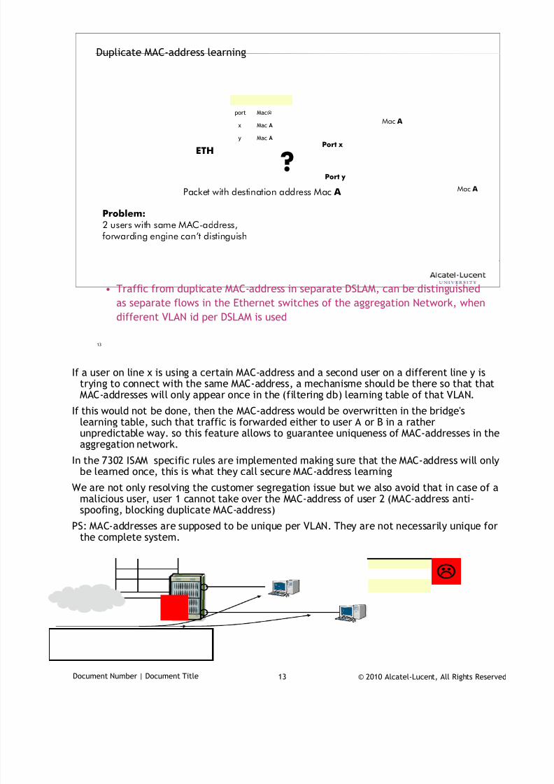
7/18/2019 Alu - A7302 Isam Fttu Operator Gpon Nant-e_ce-PDF
http://slidepdf.com/reader/full/alu-a7302-isam-fttu-operator-gpon-nant-ece-pdf 271/432
© 2010 Alcatel-Lucent, All Rights ReservedDocument Number | Document Title 13
13
Duplicate MAC-address learning
• Traffic from duplicate MAC-address in separate DSLAM, can be distinguished
as separate flows in the Ethernet switches of the aggregation Network, when
different VLAN id per DSLAM is used
Mac Ax
Mac Ay
Mac@port
Mac A
Mac A
ETHPort x
Port y
Packet with destination address Mac A
Problem:2 users with same MAC-address,forwarding engine can’t distinguish
?
If a user on line x is using a certain MAC-address and a second user on a different line y is
trying to connect with the same MAC-address, a mechanisme should be there so that thatMAC-addresses will only appear once in the (filtering db) learning table of that VLAN.
If this would not be done, then the MAC-address would be overwritten in the bridge'slearning table, such that traffic is forwarded either to user A or B in a ratherunpredictable way. so this feature allows to guarantee uniqueness of MAC-addresses in theaggregation network.
In the 7302 ISAM specific rules are implemented making sure that the MAC-address will onlybe learned once, this is what they call secure MAC-address learning
We are not only resolving the customer segregation issue but we also avoid that in case of amalicious user, user 1 cannot take over the MAC-address of user 2 (MAC-address anti-
spoofing, blocking duplicate MAC-address)PS: MAC-addresses are supposed to be unique per VLAN. They are not necessarily unique for
the complete system.
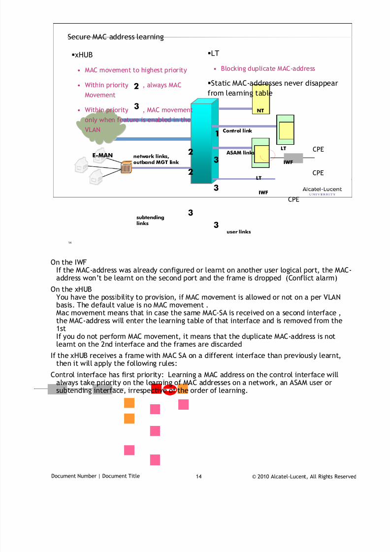
7/18/2019 Alu - A7302 Isam Fttu Operator Gpon Nant-e_ce-PDF
http://slidepdf.com/reader/full/alu-a7302-isam-fttu-operator-gpon-nant-ece-pdf 272/432
© 2010 Alcatel-Lucent, All Rights ReservedDocument Number | Document Title 14
14
CPE
Secure MAC address learning
xHUB
• MAC movement to highest priority
• Within priority , always MAC
Movement
• Within priority , MAC movement
only when feature is enabled in the
VLAN
LT
• Blocking duplicate MAC-address
Static MAC-addresses never disappear
from learning table
user links
subtendinglinks
E-MAN network links,outband MGT link
ASAM links
NT
LT
LT
Control link
IWF
IWF
1
2
3
3
3
3
2
2
3
CPE
CPE
On the IWF
If the MAC-address was already configured or learnt on another user logical port, the MAC-address won’t be learnt on the second port and the frame is dropped (Conflict alarm)
On the xHUBYou have the possibility to provision, if MAC movement is allowed or not on a per VLANbasis. The default value is no MAC movement .Mac movement means that in case the same MAC-SA is received on a second interface ,the MAC-address will enter the learning table of that interface and is removed from the1stIf you do not perform MAC movement, it means that the duplicate MAC-address is notlearnt on the 2nd interface and the frames are discarded
If the xHUB receives a frame with MAC SA on a different interface than previously learnt,then it will apply the following rules:
Control interface has first priority: Learning a MAC address on the control interface willalways take priority on the learning of MAC addresses on a network, an ASAM user orsubtending interface, irrespective of the order of learning.

7/18/2019 Alu - A7302 Isam Fttu Operator Gpon Nant-e_ce-PDF
http://slidepdf.com/reader/full/alu-a7302-isam-fttu-operator-gpon-nant-ece-pdf 273/432
© 2010 Alcatel-Lucent, All Rights ReservedDocument Number | Document Title 15
Network interface has second priority: In case the MAC address is first learnt on asubtending, ASAM or user port, and then on an Ethernet network interface, then thismovement of the MAC address will be learnt (meaning that the MAC address on thesubtending, user or ASAM port is removed). In case the Duplicate MAC-address is learnt ona network interface but it was learnt before on another NW interface the last one takespriority.
ASAM link, subtending link, user link have third priority. If the duplicate MAC address isreceived on a ASAM, user or subtending port, and the same MAC address is already learnton an Ethernet network interface in the same VLAN, then the MAC address is not learntand the frame is dropped.
If the duplicate MAC address is learnt on a DSLAM, user or subtending port, and the sameMAC address was already learnt on a port within this priority the action will depend on theconfiguration of the VLAN. ( MAC movement allowed or not – configurable per VLAN).
Well-known MAC addresses (e.g., MAC addresses allocated for IEEE protocols, ...) will not belearnt. Also the MAC address of the xHUB is a well known MAC address.
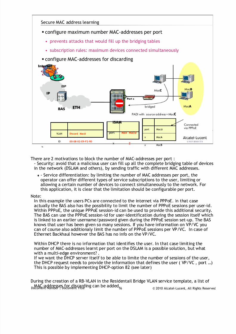
7/18/2019 Alu - A7302 Isam Fttu Operator Gpon Nant-e_ce-PDF
http://slidepdf.com/reader/full/alu-a7302-isam-fttu-operator-gpon-nant-ece-pdf 274/432
© 2010 Alcatel-Lucent, All Rights ReservedDocument Number | Document Title 16
16
Secure MAC address learning
configure maximum number MAC-addresses per port
• prevents attacks that would fill up the bridging tables
• subscription rules: maximum devices connected simultaneously
configure MAC-addresses for discarding
2x
Max Mac@port
Mac A
ETH
Port x
Connectedvia PPPoE
MacBMacC
bridged
IP
Internet
ISP
BAS
MacAx
MacBx
Mac@port
PADI with source address=MacC
ISAM
00-08-02-E9-F2-9DID
Discard Mac@VLAN
There are 2 motivations to block the number of MAC-addresses per port :
- Security: avoid that a malicious user can fill up all the complete bridging table of devicesin the network (DSLAM and others), by sending traffic with different MAC addresses.
- Service differentiation: by limiting the number of MAC addresses per port, theoperator can offer different types of service subscriptions to the user, limiting orallowing a certain number of devices to connect simultaneously to the network. Forthis application, it is clear that the limitation should be configurable per port.
Note:In this example the users PCs are connected to the internet via PPPoE. In that caseactually the BAS also has the possibility to limit the number of PPPoE sessions per user-id.Within PPPoE, the unique PPPoE session-id can be used to provide this additional security.
The BAS can use the PPPoE session-id for user-identification during the session itself whichis linked to an earlier username/password given during the PPPoE session set-up. The BASknows that user has been given so many sessions. If you have information on VP/VC youcan of course also additionaly limit the number of PPPoE sessions per VP/VC. In case ofEthernet Backhaul however the BAS has no info on the VP/VC.
Within DHCP there is no information that identifies the user. In that case limiting thenumber of MAC-addresses learnt per port on the DSLAM is a possible solution, but whatwith a multi-edge environment? .If we want the DHCP server itself to be able to limite the number of sessions of the user,the DHCP request needs to provide the information that defines the user ( VP/VC , port …)This is possible by implementing DHCP-option 82 (see later)
During the creation of a RB-VLAN in the Residentail Bridge VLAN service template, a list ofMAC-addresses for discarding can be added.

7/18/2019 Alu - A7302 Isam Fttu Operator Gpon Nant-e_ce-PDF
http://slidepdf.com/reader/full/alu-a7302-isam-fttu-operator-gpon-nant-ece-pdf 275/432
© 2010 Alcatel-Lucent, All Rights ReservedDocument Number | Document Title 17
17
Configuration
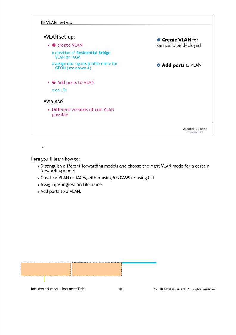
7/18/2019 Alu - A7302 Isam Fttu Operator Gpon Nant-e_ce-PDF
http://slidepdf.com/reader/full/alu-a7302-isam-fttu-operator-gpon-nant-ece-pdf 276/432
© 2010 Alcatel-Lucent, All Rights ReservedDocument Number | Document Title 18
18
IB VLAN set-up
VLAN set-up:
• create VLAN
o creation of Residential BridgeVLAN on IACM
o assign qos ingress profile name forGPON (see annex A)
• Add ports to VLAN
o on LTs
Via AMS
• Different versions of one VLANpossible
Create VLAN forservice to be deployed
Add ports to VLAN
Here you’ll learn how to:
Distinguish different forwarding models and choose the right VLAN mode for a certainforwarding model
Create a VLAN on IACM, either using 5520AMS or using CLI
Assign qos ingress profile name
Add ports to a VLAN.
7/18/2019 Alu - A7302 Isam Fttu Operator Gpon Nant-e_ce-PDF
http://slidepdf.com/reader/full/alu-a7302-isam-fttu-operator-gpon-nant-ece-pdf 277/432
© 2010 Alcatel-Lucent, All Rights ReservedDocument Number | Document Title 19
Routed mode: Forwarding decision in IACM is based on L3 (IP forwarding) . xHUBbehaves as a Full router.
L2 terminated on IACM: association with V-VLAN based on IP DA.
In Cross-connect mode different models exist
C-VLAN cross-connect : Straightforward VLAN cross-connect model where oneor more VLANs at the EMAN side are associated with a given PVC at the userside
CC on IACM : only one end-user port (PVC or bridge port EFM) associated toa specific C-VLAN
CC on shub: since there’s only one user associated to a specific C-VLAN onthe xHUB, one ASAM-link and one or more network ports are associated tothe VLAN
S-VLAN at the EMAN side is associated with a PVC at the user side, the C-VLANscarried within the S-VLAN are then passed transparently to the end user.
CC on IACM : only one end-user port (PVC or bridge port EFM) associated toa specific S-VLAN
CC on SHUB: since there’s only one user associated to a specific S-VLAN onthe xHUB one ASAM-link and one or more network ports are associated tothe S-VLAN
S-VLAN/C-VLAN cross-connect mode : PVC – C-VLAN mapping, where the S-VLAN tag can be used by the EMAN as route-identifier towards the ISAM
CC on IACM : Different end-user ports (PVC or bridge port EFM) can be
associated to a specific S-VLAN.The C-VLAN identifies the user-port
CC on SHUB: since there’s can be many users associated to a specific S-VLAN on the xHUB all ASAM-link and one or more network ports areassociated to the VLAN.
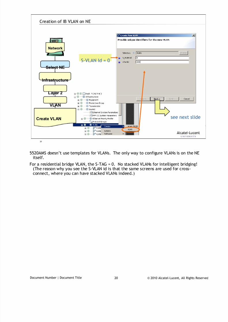
7/18/2019 Alu - A7302 Isam Fttu Operator Gpon Nant-e_ce-PDF
http://slidepdf.com/reader/full/alu-a7302-isam-fttu-operator-gpon-nant-ece-pdf 278/432
© 2010 Alcatel-Lucent, All Rights ReservedDocument Number | Document Title 20
20
Creation of IB VLAN on NE
Network
Select NE
Infrastructure
Layer 2
Create VLAN
VLAN
see next slide
S-VLAN Id = 0
5520AMS doesn’t use templates for VLANs. The only way to configure VLANs is on the NE
itself.
For a residential bridge VLAN, the S-TAG = 0. No stacked VLANs for intelligent bridging!(The reason why you see the S-VLAN id is that the same screens are used for cross-connect, where you can have stacked VLANs indeed.)
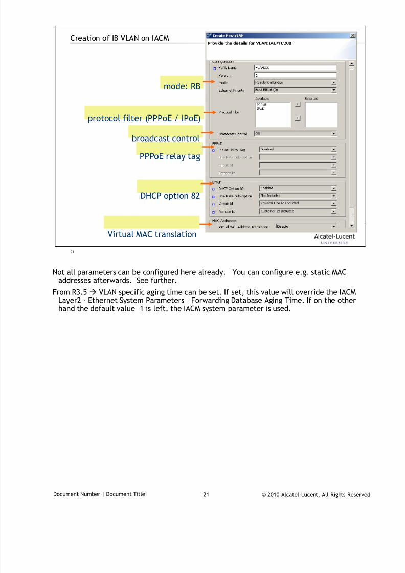
7/18/2019 Alu - A7302 Isam Fttu Operator Gpon Nant-e_ce-PDF
http://slidepdf.com/reader/full/alu-a7302-isam-fttu-operator-gpon-nant-ece-pdf 279/432
© 2010 Alcatel-Lucent, All Rights ReservedDocument Number | Document Title 21
21
Creation of IB VLAN on IACM
mode: RB
protocol filter (PPPoE / IPoE)
Virtual MAC translation
DHCP option 82
PPPoE relay tag
broadcast control
Not all parameters can be configured here already. You can configure e.g. static MAC
addresses afterwards. See further.
From R3.5 VLAN specific aging time can be set. If set, this value will override the IACMLayer2 - Ethernet System Parameters – Forwarding Database Aging Time. If on the otherhand the default value –1 is left, the IACM system parameter is used.
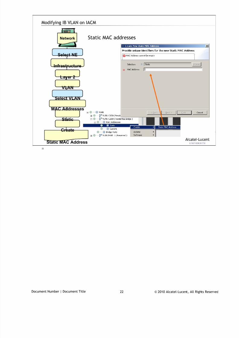
7/18/2019 Alu - A7302 Isam Fttu Operator Gpon Nant-e_ce-PDF
http://slidepdf.com/reader/full/alu-a7302-isam-fttu-operator-gpon-nant-ece-pdf 280/432
© 2010 Alcatel-Lucent, All Rights ReservedDocument Number | Document Title 22
22
Modifying IB VLAN on IACM
Static MAC addressesNetwork
Select NE
Infrastructure
Layer 2
Static MAC Address
VLAN
Select VLAN
MAC Addresses
Static
Create
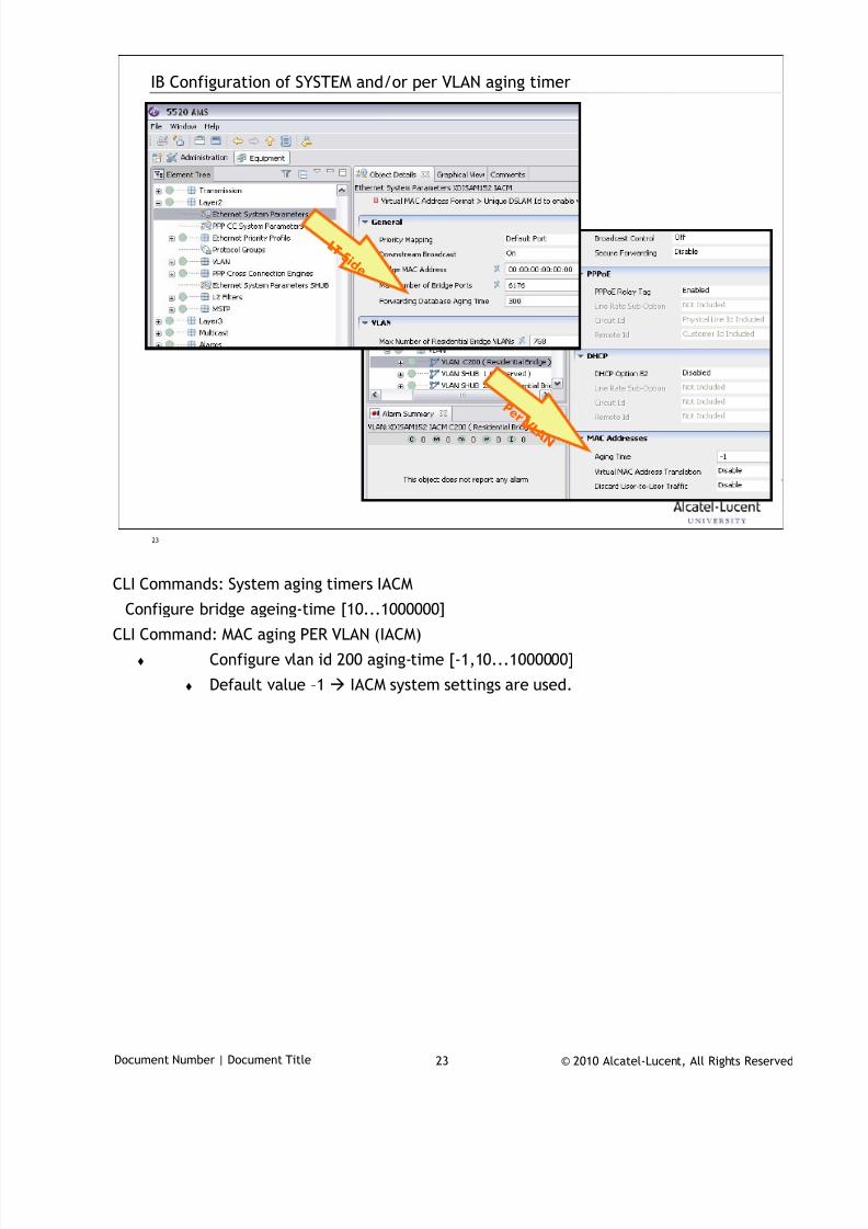
7/18/2019 Alu - A7302 Isam Fttu Operator Gpon Nant-e_ce-PDF
http://slidepdf.com/reader/full/alu-a7302-isam-fttu-operator-gpon-nant-ece-pdf 281/432
© 2010 Alcatel-Lucent, All Rights ReservedDocument Number | Document Title 23
23
IB Configuration of SYSTEM and/or per VLAN aging timer
L T S i d e
P e r V L A N
CLI Commands: System aging timers IACM
Configure bridge ageing-time [10...1000000]
CLI Command: MAC aging PER VLAN (IACM)
Configure vlan id 200 aging-time [-1,10...1000000]
Default value –1 IACM system settings are used.
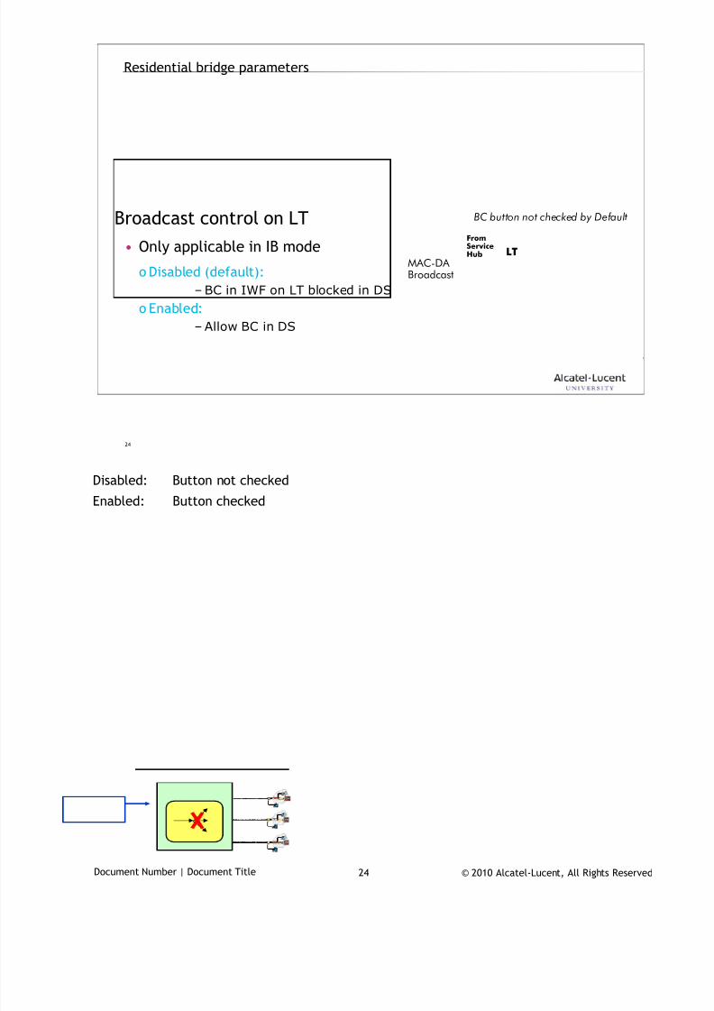
7/18/2019 Alu - A7302 Isam Fttu Operator Gpon Nant-e_ce-PDF
http://slidepdf.com/reader/full/alu-a7302-isam-fttu-operator-gpon-nant-ece-pdf 282/432
© 2010 Alcatel-Lucent, All Rights ReservedDocument Number | Document Title 24
24
Residential bridge parameters
Broadcast control on LT
• Only applicable in IB mode
o Disabled (default):
– BC in IWF on LT blocked in DS
o Enabled:
– Allow BC in DS
BC button not checked by Default
LT
FromServiceHub
MAC-DA Broadcast
Disabled: Button not checked
Enabled: Button checked
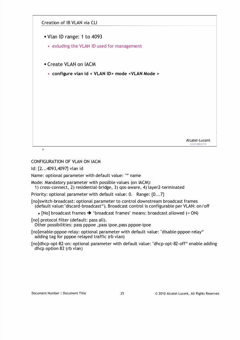
7/18/2019 Alu - A7302 Isam Fttu Operator Gpon Nant-e_ce-PDF
http://slidepdf.com/reader/full/alu-a7302-isam-fttu-operator-gpon-nant-ece-pdf 283/432
© 2010 Alcatel-Lucent, All Rights ReservedDocument Number | Document Title 25
25
Creation of IB VLAN via CLI
Vlan ID range: 1 to 4093
• exluding the VLAN ID used for management
Create VLAN on IACM
• configure vlan id < VLAN ID> mode <VLAN Mode >
CONFIGURATION OF VLAN ON IACM
Id: [2...4093,4097] vlan id
Name: optional parameter with default value: "“ name
Mode: Mandatory parameter with possible values (on IACM):1) cross-connect, 2) residential-bridge, 3) qos-aware, 4) layer2-terminated
Priority: optional parameter with default value: 0. Range: {0...7}
[no]switch-broadcast: optional parameter to control downstream broadcast frames(default value:"discard-broadcast“). Broadcast control is configurable per VLAN: on/off
[No] broadcast frames ‘broadcast frames’ means: broadcast allowed (= ON)
[no] protocol filter (default: pass all).Other possibilities: pass pppoe ,pass ipoe,pass pppoe-ipoe
[no]enable-pppoe-relay: optional parameter with default value: "disable-pppoe-relay“adding tag for pppoe relayed traffic (rb vlan)
[no]dhcp-opt-82-on: optional parameter with default value: "dhcp-opt-82-off“ enable addingdhcp option 82 (rb vlan)
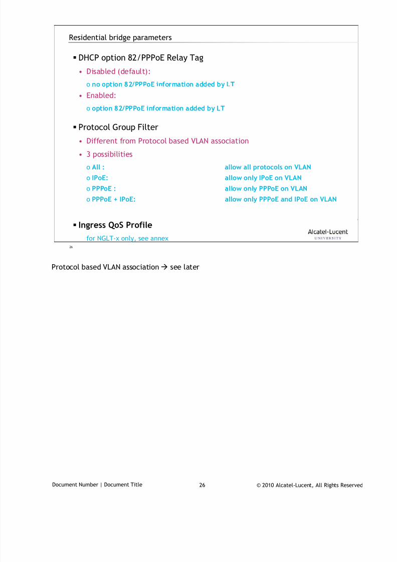
7/18/2019 Alu - A7302 Isam Fttu Operator Gpon Nant-e_ce-PDF
http://slidepdf.com/reader/full/alu-a7302-isam-fttu-operator-gpon-nant-ece-pdf 284/432
© 2010 Alcatel-Lucent, All Rights ReservedDocument Number | Document Title 26
26
Residential bridge parameters
DHCP option 82/PPPoE Relay Tag
• Disabled (default):
o no option 82/PPPoE information added by LT
• Enabled:
o option 82/PPPoE information added by LT
Protocol Group Filter
• Different from Protocol based VLAN association
• 3 possibilities
o All : allow all protocols on VLAN
o IPoE: allow only IPoE on VLAN
o PPPoE : allow only PPPoE on VLAN
o PPPoE + IPoE: allow only PPPoE and IPoE on VLAN
Ingress QoS Profile
for NGLT-x only, see annex
Protocol based VLAN association see later
7/18/2019 Alu - A7302 Isam Fttu Operator Gpon Nant-e_ce-PDF
http://slidepdf.com/reader/full/alu-a7302-isam-fttu-operator-gpon-nant-ece-pdf 285/432
© 2010 Alcatel-Lucent, All Rights ReservedDocument Number | Document Title 27
27
IB VLAN association
on bridge port
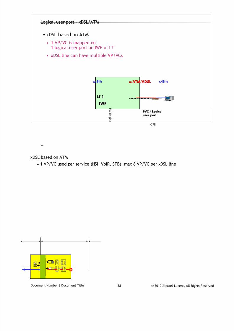
7/18/2019 Alu - A7302 Isam Fttu Operator Gpon Nant-e_ce-PDF
http://slidepdf.com/reader/full/alu-a7302-isam-fttu-operator-gpon-nant-ece-pdf 286/432
© 2010 Alcatel-Lucent, All Rights ReservedDocument Number | Document Title 28
28
Logical user port – xDSL/ATM
xDSL based on ATM
• 1 VP/VC is mapped on1 logical user port on IWF of LT
• xDSL line can have multiple VP/VCs
LT 1
PVC / Logicaluser port
CPE
x/ATM/ADSL x/Eth x/Eth
IWFF W
E n gi n e
xDSL based on ATM
1 VP/VC used per service (HSI, VoIP, STB), max 8 VP/VC per xDSL line
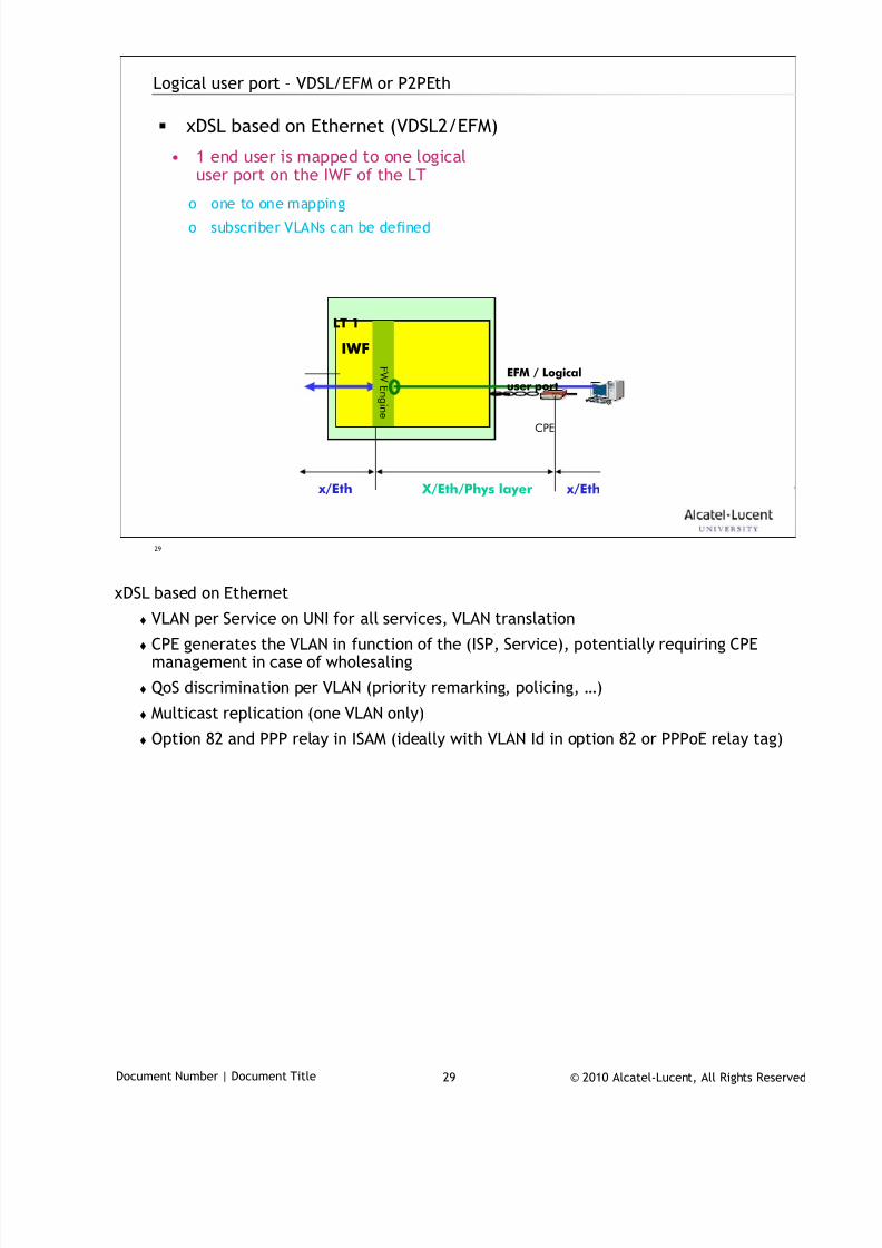
7/18/2019 Alu - A7302 Isam Fttu Operator Gpon Nant-e_ce-PDF
http://slidepdf.com/reader/full/alu-a7302-isam-fttu-operator-gpon-nant-ece-pdf 287/432
© 2010 Alcatel-Lucent, All Rights ReservedDocument Number | Document Title 29
29
Logical user port – VDSL/EFM or P2PEth
xDSL based on Ethernet (VDSL2/EFM)
• 1 end user is mapped to one logicaluser port on the IWF of the LT
o one to one mapping
o subscriber VLANs can be defined
LT 1
CPE
x/Eth x/Eth
IWFF W
E n
gi n e
EFM / Logicaluser port
X/Eth/Phys layer
xDSL based on Ethernet
VLAN per Service on UNI for all services, VLAN translation
CPE generates the VLAN in function of the (ISP, Service), potentially requiring CPEmanagement in case of wholesaling
QoS discrimination per VLAN (priority remarking, policing, …)
Multicast replication (one VLAN only)
Option 82 and PPP relay in ISAM (ideally with VLAN Id in option 82 or PPPoE relay tag)
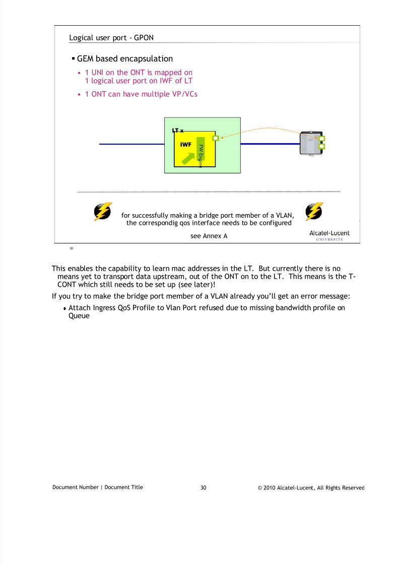
7/18/2019 Alu - A7302 Isam Fttu Operator Gpon Nant-e_ce-PDF
http://slidepdf.com/reader/full/alu-a7302-isam-fttu-operator-gpon-nant-ece-pdf 288/432
© 2010 Alcatel-Lucent, All Rights ReservedDocument Number | Document Title 30
30
Logical user port - GPON
GEM based encapsulation
• 1 UNI on the ONT is mapped on1 logical user port on IWF of LT
• 1 ONT can have multiple VP/VCs
LT x
IWF F W
E n gi n e
for successfully making a bridge port member of a VLAN,the correspondig qos interface needs to be configured
see Annex A
This enables the capability to learn mac addresses in the LT. But currently there is no
means yet to transport data upstream, out of the ONT on to the LT. This means is the T-CONT which still needs to be set up (see later)!
If you try to make the bridge port member of a VLAN already you’ll get an error message:
Attach Ingress QoS Profile to Vlan Port refused due to missing bandwidth profile onQueue
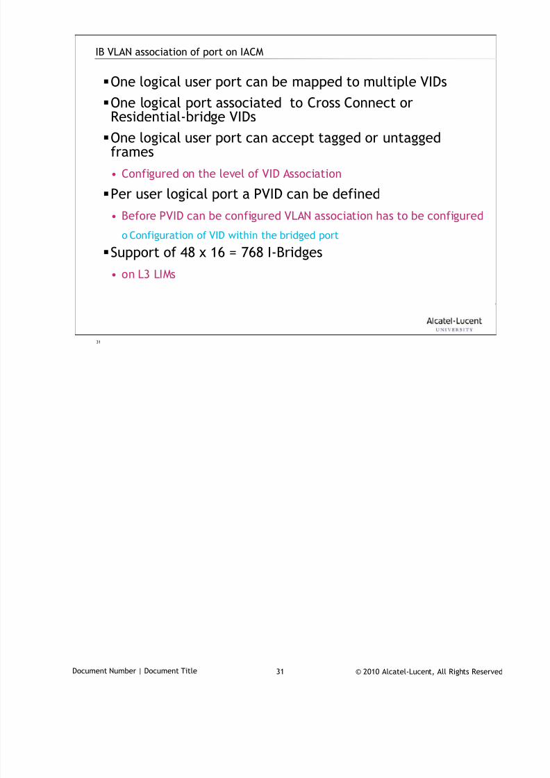
7/18/2019 Alu - A7302 Isam Fttu Operator Gpon Nant-e_ce-PDF
http://slidepdf.com/reader/full/alu-a7302-isam-fttu-operator-gpon-nant-ece-pdf 289/432
© 2010 Alcatel-Lucent, All Rights ReservedDocument Number | Document Title 31
31
IB VLAN association of port on IACM
One logical user port can be mapped to multiple VIDs
One logical port associated to Cross Connect orResidential-bridge VIDs
One logical user port can accept tagged or untaggedframes
• Configured on the level of VID Association
Per user logical port a PVID can be defined
• Before PVID can be configured VLAN association has to be configured
o Configuration of VID within the bridged port
Support of 48 x 16 = 768 I-Bridges• on L3 LIMs
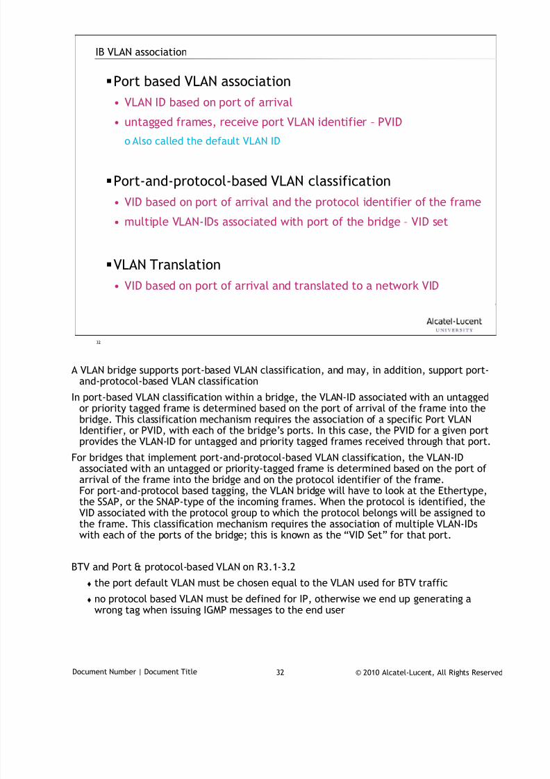
7/18/2019 Alu - A7302 Isam Fttu Operator Gpon Nant-e_ce-PDF
http://slidepdf.com/reader/full/alu-a7302-isam-fttu-operator-gpon-nant-ece-pdf 290/432
© 2010 Alcatel-Lucent, All Rights ReservedDocument Number | Document Title 32
32
IB VLAN association
Port based VLAN association
• VLAN ID based on port of arrival
• untagged frames, receive port VLAN identifier – PVIDo Also called the default VLAN ID
Port-and-protocol-based VLAN classification
• VID based on port of arrival and the protocol identifier of the frame
• multiple VLAN-IDs associated with port of the bridge – VID set
VLAN Translation
• VID based on port of arrival and translated to a network VID
A VLAN bridge supports port-based VLAN classification, and may, in addition, support port-
and-protocol-based VLAN classification
In port-based VLAN classification within a bridge, the VLAN-ID associated with an untaggedor priority tagged frame is determined based on the port of arrival of the frame into thebridge. This classification mechanism requires the association of a specific Port VLANIdentifier, or PVID, with each of the bridge’s ports. In this case, the PVID for a given portprovides the VLAN-ID for untagged and priority tagged frames received through that port.
For bridges that implement port-and-protocol-based VLAN classification, the VLAN-IDassociated with an untagged or priority-tagged frame is determined based on the port ofarrival of the frame into the bridge and on the protocol identifier of the frame.For port-and-protocol based tagging, the VLAN bridge will have to look at the Ethertype,
the SSAP, or the SNAP-type of the incoming frames. When the protocol is identified, theVID associated with the protocol group to which the protocol belongs will be assigned tothe frame. This classification mechanism requires the association of multiple VLAN-IDswith each of the ports of the bridge; this is known as the “VID Set” for that port.
BTV and Port & protocol-based VLAN on R3.1-3.2
the port default VLAN must be chosen equal to the VLAN used for BTV traffic
no protocol based VLAN must be defined for IP, otherwise we end up generating awrong tag when issuing IGMP messages to the end user
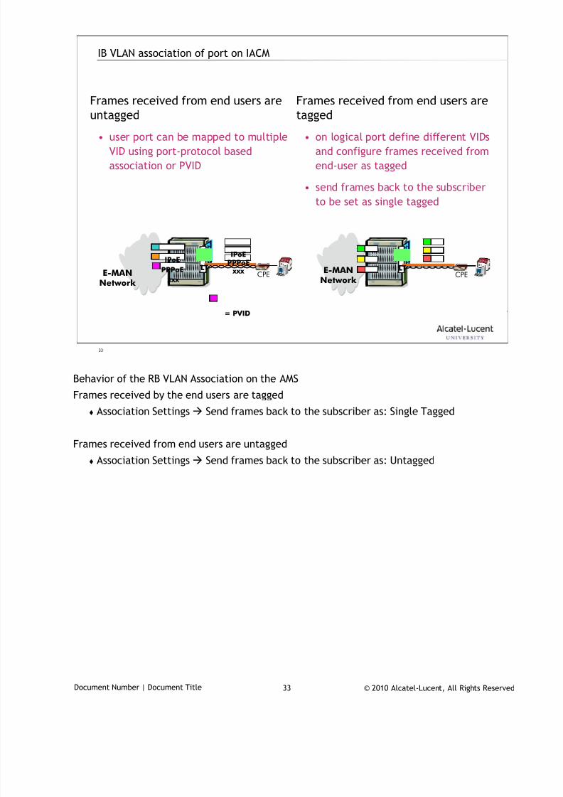
7/18/2019 Alu - A7302 Isam Fttu Operator Gpon Nant-e_ce-PDF
http://slidepdf.com/reader/full/alu-a7302-isam-fttu-operator-gpon-nant-ece-pdf 291/432
© 2010 Alcatel-Lucent, All Rights ReservedDocument Number | Document Title 33
33
IB VLAN association of port on IACM
Frames received from end users are
untagged
• user port can be mapped to multiple
VID using port-protocol based
association or PVID
Frames received from end users are
tagged
• on logical port define different VIDs
and configure frames received from
end-user as tagged
• send frames back to the subscriber
to be set as single tagged
E-MANNetwork
CPELT
E-MANNetwork
CPELT
IPoE PPPoE xxx
= PVID
IPoE
PPPoE
xxx
Behavior of the RB VLAN Association on the AMS
Frames received by the end users are tagged
Association Settings Send frames back to the subscriber as: Single Tagged
Frames received from end users are untagged
Association Settings Send frames back to the subscriber as: Untagged
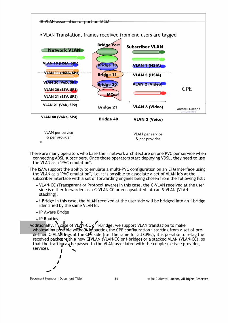
7/18/2019 Alu - A7302 Isam Fttu Operator Gpon Nant-e_ce-PDF
http://slidepdf.com/reader/full/alu-a7302-isam-fttu-operator-gpon-nant-ece-pdf 292/432
© 2010 Alcatel-Lucent, All Rights ReservedDocument Number | Document Title 34
34
IB VLAN association of port on IACM
VLAN Translation, frames received from end users are tagged
VLAN per service& per provider
VLAN per service& per provider
VLAN 1 (HSIA)Bridge 10 VLAN 10 (HSIA, SP1)
VLAN 2 (Video)Bridge 20 VLAN 20 (VoD, SP1)
MCast
VLAN 30 (BTV, SP1)
VLAN 3 (Voice)Bridge 40 VLAN 40 (Voice, SP3)
VLAN 5 (HSIA)Bridge 11 VLAN 11 (HSIA, SP2)
VLAN 6 (Video)Bridge 21 VLAN 21 (VoD, SP2)
VLAN 31 (BTV, SP2)
Subscriber VLAN
Network VLAN
Bridge Port
CPE
There are many operators who base their network architecture on one PVC per service when
connecting ADSL subscribers. Once those operators start deploying VDSL, they need to usethe VLAN as a "PVC emulation".
The ISAM support the ability to emulate a multi-PVC configuration on an EFM interface usingthe VLAN as a "PVC emulation", i.e. it is possible to associate a set of VLAN Id's at thesubscriber interface with a set of forwarding engines being chosen from the following list :
VLAN-CC (Transparent or Protocol aware) In this case, the C-VLAN received at the userside is either forwarded as a C-VLAN CC or encapsulated into an S-VLAN (VLANstacking).
i-Bridge In this case, the VLAN received at the user side will be bridged into an i-bridgeidentified by the same VLAN Id.
IP Aware Bridge
IP Routing
Additionally, in case of VLAN-CC or i-Bridge, we support VLAN translation to makewholesaling possible without impacting the CPE configuration : starting from a set of pre-defined C-VLAN tags at the CPE side (i.e. the same for all CPEs), it is possible to retag thereceived packet with a new C-VLAN (VLAN-CC or i-bridge) or a stacked VLAN (VLAN-CC), sothat the traffic can be passed to the VLAN associated with the couple (serivce provider,service).
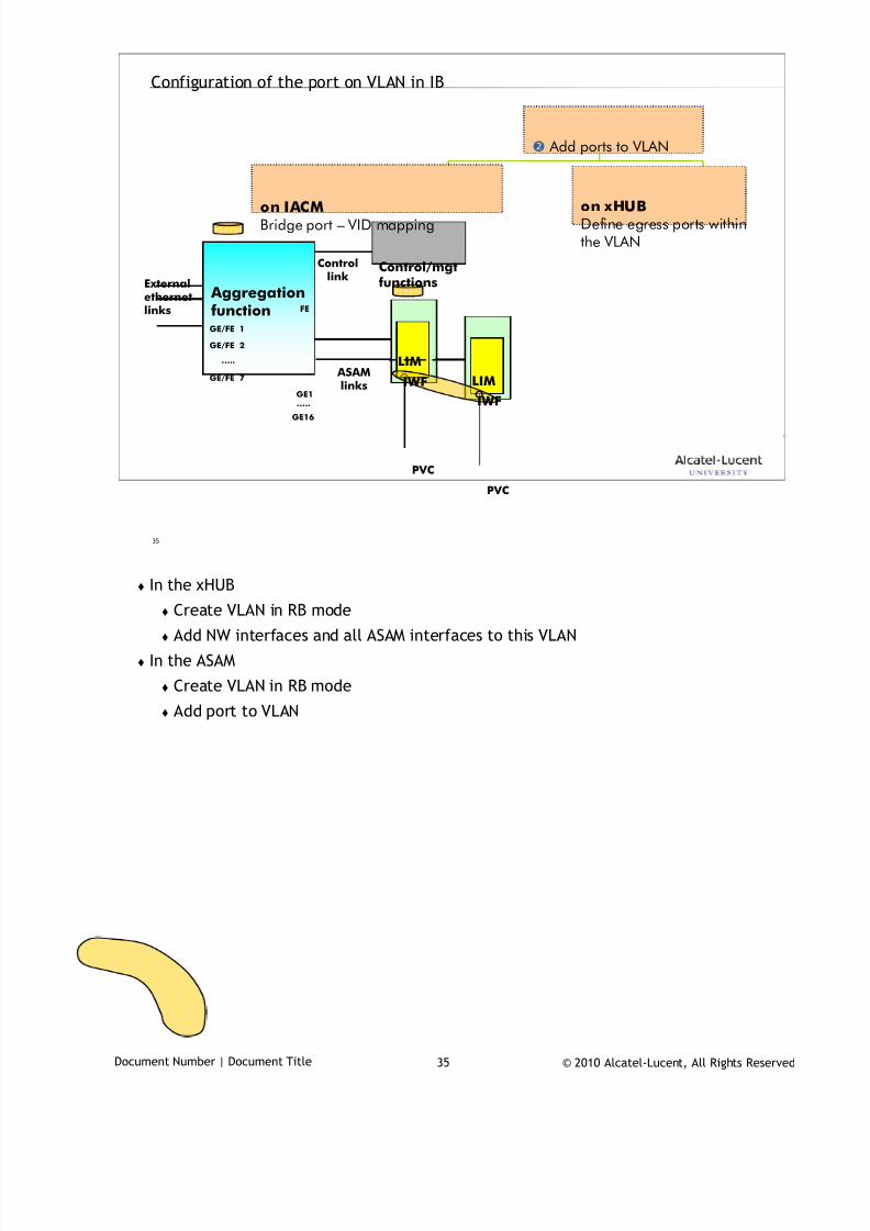
7/18/2019 Alu - A7302 Isam Fttu Operator Gpon Nant-e_ce-PDF
http://slidepdf.com/reader/full/alu-a7302-isam-fttu-operator-gpon-nant-ece-pdf 293/432
© 2010 Alcatel-Lucent, All Rights ReservedDocument Number | Document Title 35
35
Configuration of the port on VLAN in IB
Add ports to VLAN
on IACMBridge port – VID mapping
on xHUBDefine egress ports withinthe VLAN
Aggregationfunction
GE1
Externalethernetlinks
ASAMlinks
Controllink
FE
LIM
IWF
Control/mgtfunctions
GE16
LIM
IWF
PVC
…..
PVC
GE/FE 1
GE/FE 2
…..
GE/FE 7
In the xHUB
Create VLAN in RB mode
Add NW interfaces and all ASAM interfaces to this VLAN
In the ASAM
Create VLAN in RB mode
Add port to VLAN
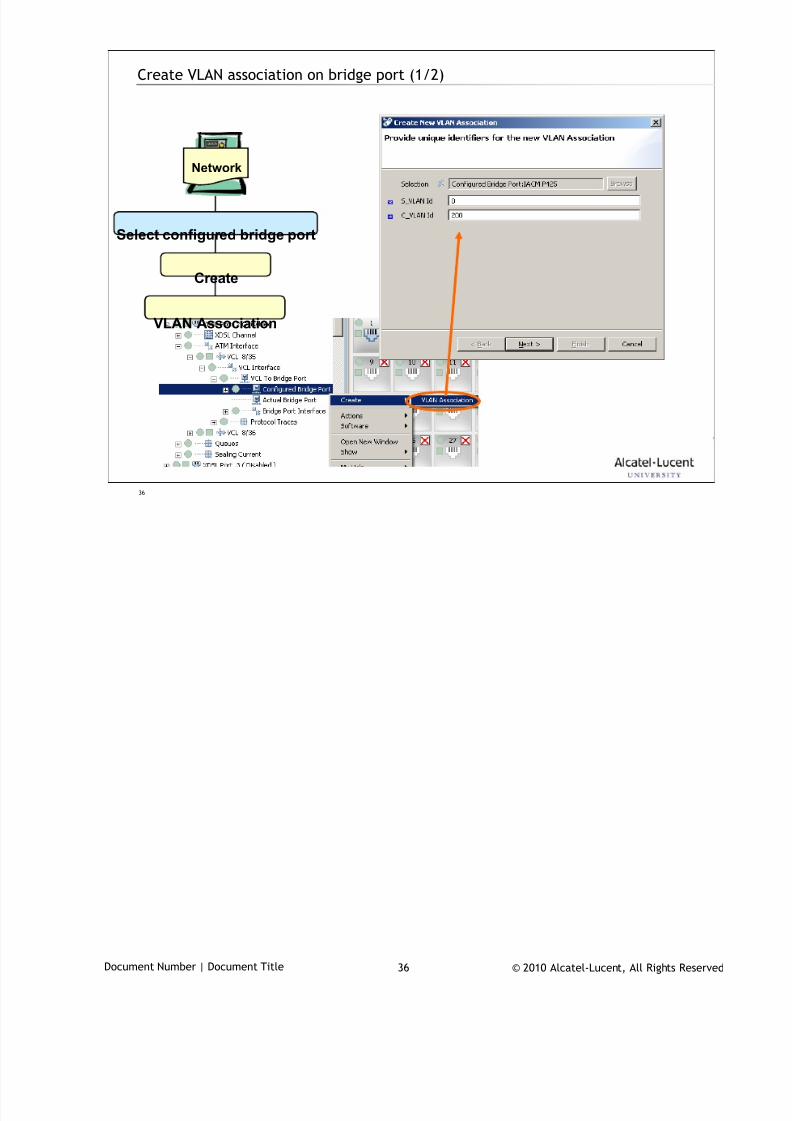
7/18/2019 Alu - A7302 Isam Fttu Operator Gpon Nant-e_ce-PDF
http://slidepdf.com/reader/full/alu-a7302-isam-fttu-operator-gpon-nant-ece-pdf 294/432
© 2010 Alcatel-Lucent, All Rights ReservedDocument Number | Document Title 36
36
Create VLAN association on bridge port (1/2)
Network
Select configured bridge port
Create
VLAN Association
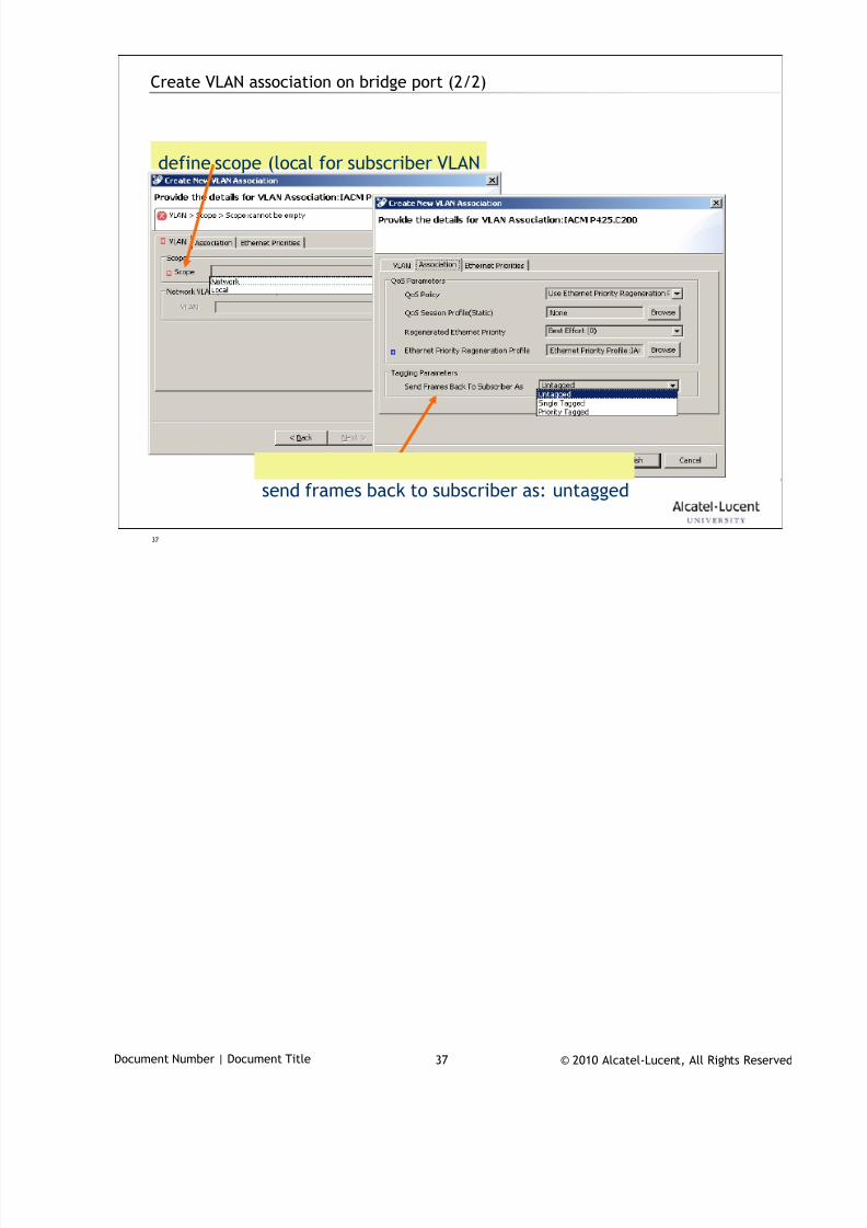
7/18/2019 Alu - A7302 Isam Fttu Operator Gpon Nant-e_ce-PDF
http://slidepdf.com/reader/full/alu-a7302-isam-fttu-operator-gpon-nant-ece-pdf 295/432
© 2010 Alcatel-Lucent, All Rights ReservedDocument Number | Document Title 37
37
Create VLAN association on bridge port (2/2)
define scope (local for subscriber VLAN
send frames back to subscriber as: untagged
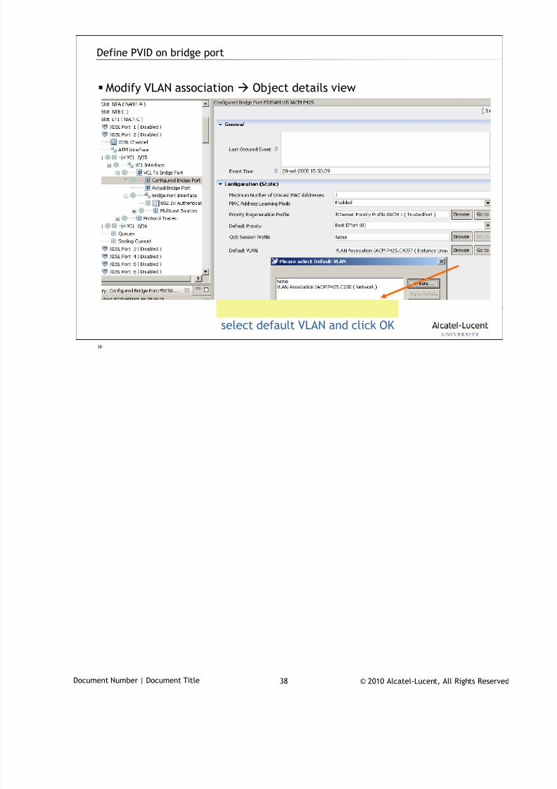
7/18/2019 Alu - A7302 Isam Fttu Operator Gpon Nant-e_ce-PDF
http://slidepdf.com/reader/full/alu-a7302-isam-fttu-operator-gpon-nant-ece-pdf 296/432
© 2010 Alcatel-Lucent, All Rights ReservedDocument Number | Document Title 38
38
Define PVID on bridge port
Modify VLAN association Object details view
select default VLAN and click OK
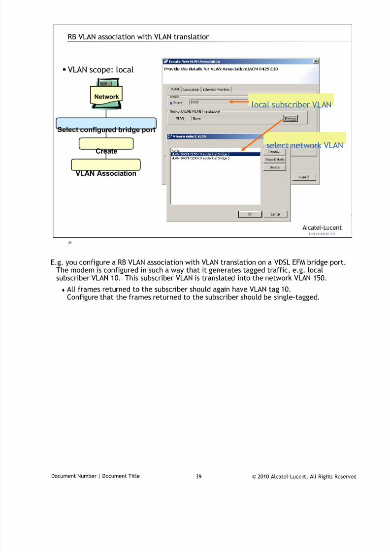
7/18/2019 Alu - A7302 Isam Fttu Operator Gpon Nant-e_ce-PDF
http://slidepdf.com/reader/full/alu-a7302-isam-fttu-operator-gpon-nant-ece-pdf 297/432
© 2010 Alcatel-Lucent, All Rights ReservedDocument Number | Document Title 39
39
RB VLAN association with VLAN translation
VLAN scope: local
Network
Select configured bridge port
Create
VLAN Association
local subscriber VLAN
select network VLAN
E.g. you configure a RB VLAN association with VLAN translation on a VDSL EFM bridge port.
The modem is configured in such a way that it generates tagged traffic, e.g. localsubscriber VLAN 10. This subscriber VLAN is translated into the network VLAN 150.
All frames returned to the subscriber should again have VLAN tag 10.Configure that the frames returned to the subscriber should be single-tagged.
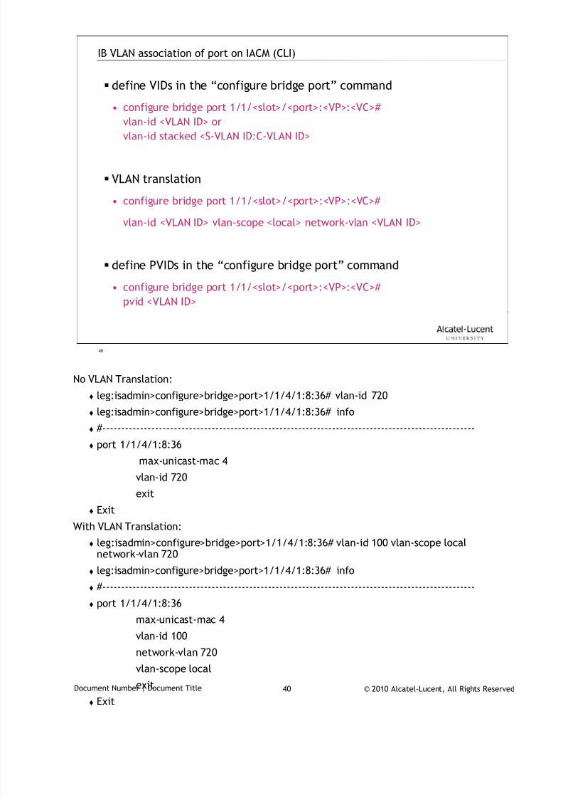
7/18/2019 Alu - A7302 Isam Fttu Operator Gpon Nant-e_ce-PDF
http://slidepdf.com/reader/full/alu-a7302-isam-fttu-operator-gpon-nant-ece-pdf 298/432
© 2010 Alcatel-Lucent, All Rights ReservedDocument Number | Document Title 40
40
IB VLAN association of port on IACM (CLI)
define VIDs in the “configure bridge port” command
• configure bridge port 1/1/<slot>/<port>:<VP>:<VC>#
vlan-id <VLAN ID> or
vlan-id stacked <S-VLAN ID:C-VLAN ID>
VLAN translation
• configure bridge port 1/1/<slot>/<port>:<VP>:<VC>#
vlan-id <VLAN ID> vlan-scope <local> network-vlan <VLAN ID>
define PVIDs in the “configure bridge port” command
• configure bridge port 1/1/<slot>/<port>:<VP>:<VC>#
pvid <VLAN ID>
No VLAN Translation:
leg:isadmin>configure>bridge>port>1/1/4/1:8:36# vlan-id 720
leg:isadmin>configure>bridge>port>1/1/4/1:8:36# info
#---------------------------------------------------------------------------------------------------
port 1/1/4/1:8:36
max-unicast-mac 4
vlan-id 720
exit
Exit
With VLAN Translation:
leg:isadmin>configure>bridge>port>1/1/4/1:8:36# vlan-id 100 vlan-scope localnetwork-vlan 720
leg:isadmin>configure>bridge>port>1/1/4/1:8:36# info
#---------------------------------------------------------------------------------------------------
port 1/1/4/1:8:36
max-unicast-mac 4
vlan-id 100
network-vlan 720
vlan-scope local
exit
Exit
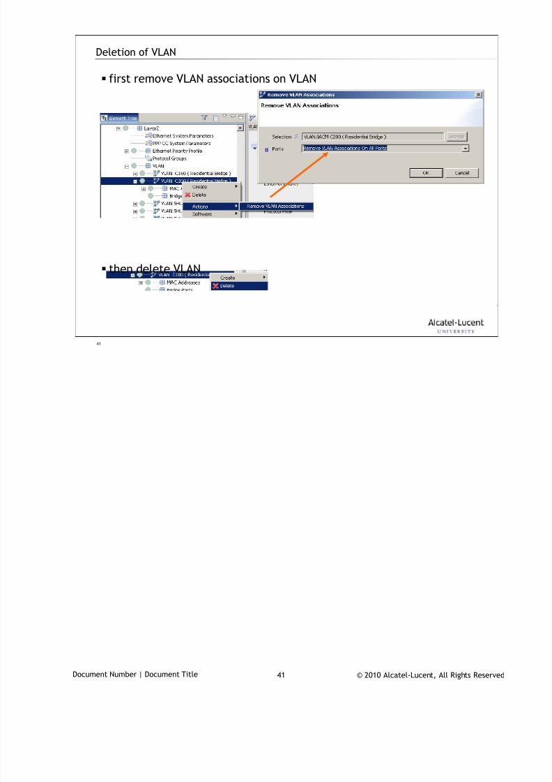
7/18/2019 Alu - A7302 Isam Fttu Operator Gpon Nant-e_ce-PDF
http://slidepdf.com/reader/full/alu-a7302-isam-fttu-operator-gpon-nant-ece-pdf 299/432
© 2010 Alcatel-Lucent, All Rights ReservedDocument Number | Document Title 41
41
Deletion of VLAN
first remove VLAN associations on VLAN
then delete VLAN
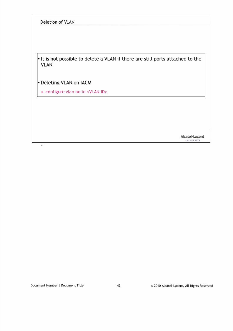
7/18/2019 Alu - A7302 Isam Fttu Operator Gpon Nant-e_ce-PDF
http://slidepdf.com/reader/full/alu-a7302-isam-fttu-operator-gpon-nant-ece-pdf 300/432
© 2010 Alcatel-Lucent, All Rights ReservedDocument Number | Document Title 42
42
Deletion of VLAN
It is not possible to delete a VLAN if there are still ports attached to the
VLAN
Deleting VLAN on IACM
• configure vlan no id <VLAN ID>
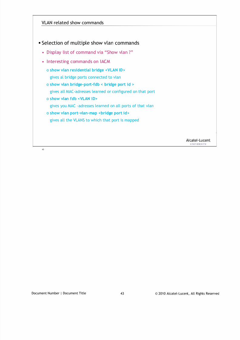
7/18/2019 Alu - A7302 Isam Fttu Operator Gpon Nant-e_ce-PDF
http://slidepdf.com/reader/full/alu-a7302-isam-fttu-operator-gpon-nant-ece-pdf 301/432
© 2010 Alcatel-Lucent, All Rights ReservedDocument Number | Document Title 43
43
VLAN related show commands
Selection of multiple show vlan commands
• Display list of command via “Show vlan ?”
• Interesting commands on IACM
o show vlan residential bridge <VLAN ID>
gives al bridge ports connected to vlan
o show vlan bridge-port-fdb < bridge port id >
gives all MAC-adresses learned or configured on that port
o show vlan fdb <VLAN ID>
gives you MAC -adresses learned on all ports of that vlan
o show vlan port-vlan-map <bridge port id>
gives all the VLANS to which that port is mapped
7/18/2019 Alu - A7302 Isam Fttu Operator Gpon Nant-e_ce-PDF
http://slidepdf.com/reader/full/alu-a7302-isam-fttu-operator-gpon-nant-ece-pdf 302/432
© 2010 Alcatel-Lucent, All Rights ReservedDocument Number | Document Title 44
44
Annex A: Basic GPON QoS configs
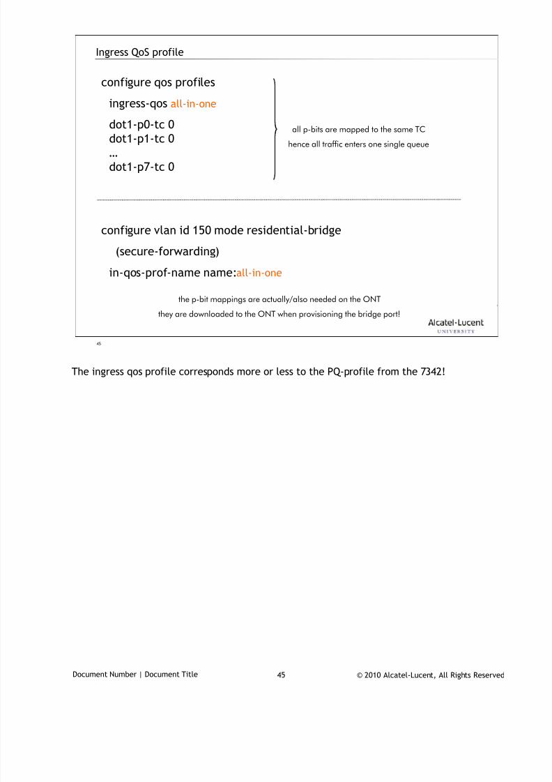
7/18/2019 Alu - A7302 Isam Fttu Operator Gpon Nant-e_ce-PDF
http://slidepdf.com/reader/full/alu-a7302-isam-fttu-operator-gpon-nant-ece-pdf 303/432
© 2010 Alcatel-Lucent, All Rights ReservedDocument Number | Document Title 45
45
Ingress QoS profile
configure qos profiles
ingress-qos all-in-one
dot1-p0-tc 0dot1-p1-tc 0
…
dot1-p7-tc 0
configure vlan id 150 mode residential-bridge
(secure-forwarding)in-qos-prof-name name:all-in-one
all p-bits are mapped to the same TC
hence all traffic enters one single queue
the p-bit mappings are actually/also needed on the ONT
they are downloaded to the ONT when provisioning the bridge port!
The ingress qos profile corresponds more or less to the PQ-profile from the 7342!

7/18/2019 Alu - A7302 Isam Fttu Operator Gpon Nant-e_ce-PDF
http://slidepdf.com/reader/full/alu-a7302-isam-fttu-operator-gpon-nant-ece-pdf 304/432
© 2010 Alcatel-Lucent, All Rights ReservedDocument Number | Document Title 46
46
Bandwidth profile
configure qos profiles
bandwidth CBR1000
committed-info-rate 1000
assured-info-rate 1000
excessive-info rate 1000
delay-tolerance 80
configure qos interface 1/1/5/1/33/1/1
upstream-queue 0 bandwidth-profile name:CBR1000
by default, one T-CONT will be assigned per queue,unless bandwidth sharing is enabled!

7/18/2019 Alu - A7302 Isam Fttu Operator Gpon Nant-e_ce-PDF
http://slidepdf.com/reader/full/alu-a7302-isam-fttu-operator-gpon-nant-ece-pdf 305/432
© 2010 Alcatel-Lucent, All Rights ReservedDocument Number | Document Title 47
47
www.alcatel-lucent.comwww.alcatel-lucent.com
7/18/2019 Alu - A7302 Isam Fttu Operator Gpon Nant-e_ce-PDF
http://slidepdf.com/reader/full/alu-a7302-isam-fttu-operator-gpon-nant-ece-pdf 306/432
© 2010 Alcatel-Lucent, All Rights ReservedTAC03048-HO04 | IHUB L3 Forwarding 1
IP routing (L3) in the IHUB
During class please switch off your mobile, pager or other that may interrupt.

7/18/2019 Alu - A7302 Isam Fttu Operator Gpon Nant-e_ce-PDF
http://slidepdf.com/reader/full/alu-a7302-isam-fttu-operator-gpon-nant-ece-pdf 307/432
© 2010 Alcatel-Lucent, All Rights ReservedTAC03048-HO04 | IHUB L3 Forwarding 2
Objective
After completing this section, you’ll be able to:
• Describe IP routing and explain why IP routing is layer 3 forwarding.
• Retrieve IP routing data from the ISAM (both with AMS and CLI)
• Configure IP routing on the ISAM (both with AMS and CLI)
Using VPRN with static user IP addresses and default route
Adding DHCP relay
Adding IP Routing protocols on the IP interface towards the network
Configure the Base Router
7/18/2019 Alu - A7302 Isam Fttu Operator Gpon Nant-e_ce-PDF
http://slidepdf.com/reader/full/alu-a7302-isam-fttu-operator-gpon-nant-ece-pdf 308/432
© 2010 Alcatel-Lucent, All Rights ReservedTAC03048-HO04 | IHUB L3 Forwarding 3
TAC03002_D_ Ed 01 P07 3 © 2009 Alcatel-Lucent., All rights reserved
3
Table of contents
1. Concepts & Principles. . . . . . . .
2. VPRN/IES IHUB configuration . . . . . . .
3. DHCP Relay IHUB Configuration . . . . . .
4. IP Routing – IS-IS protocol IHUB Configuration . . . . .
5. IP / MAC Filters . . . . . . .
6. Base Router configuration . . . . . .

7/18/2019 Alu - A7302 Isam Fttu Operator Gpon Nant-e_ce-PDF
http://slidepdf.com/reader/full/alu-a7302-isam-fttu-operator-gpon-nant-ece-pdf 309/432
© 2010 Alcatel-Lucent, All Rights ReservedTAC03048-HO04 | IHUB L3 Forwarding 4
4
Concepts & Principles1
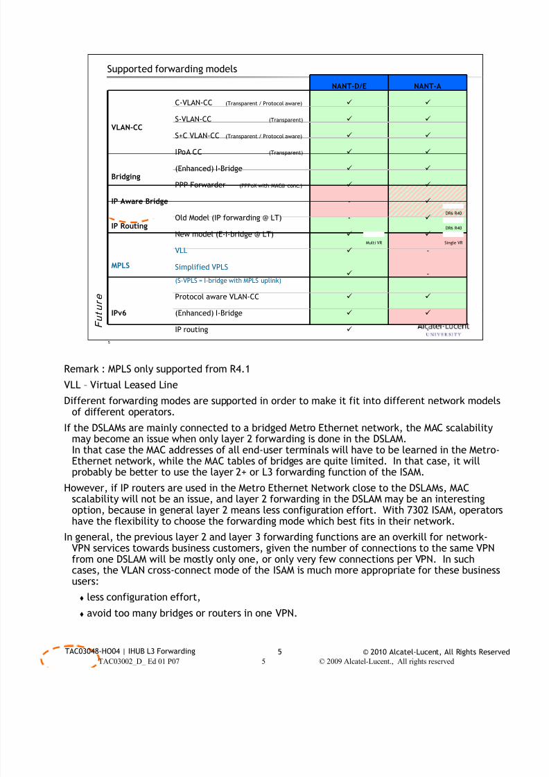
7/18/2019 Alu - A7302 Isam Fttu Operator Gpon Nant-e_ce-PDF
http://slidepdf.com/reader/full/alu-a7302-isam-fttu-operator-gpon-nant-ece-pdf 310/432
© 2010 Alcatel-Lucent, All Rights ReservedTAC03048-HO04 | IHUB L3 Forwarding 5
TAC03002_D_ Ed 01 P07 5 © 2009 Alcatel-Lucent., All rights reserved
5
Supported forwarding models
NANT-D/E NANT-A
VLAN-CC
C-VLAN-CC (Transparent / Protocol aware)
S-VLAN-CC (Transparent)
S+C VLAN-CC (Transparent / Protocol aware)
IPoA CC (Transparent)
Bridging(Enhanced) I-Bridge
PPP Forwarder (PPPoX with MAC@ conc.)
IP Aware Bridge -
IP RoutingOld Model (IP forwarding @ LT) -
New model (E-I-bridge @ LT)
MPLS
VLL -
Simplified VPLS
(S-VPLS = I-bridge with MPLS uplink) -
IPv6
Protocol aware VLAN-CC
(Enhanced) I-Bridge
IP routing -
DR6 R40
DR6 R40
F u t u r e
Single VRMulti VR
Remark : MPLS only supported from R4.1
VLL – Virtual Leased Line
Different forwarding modes are supported in order to make it fit into different network modelsof different operators.
If the DSLAMs are mainly connected to a bridged Metro Ethernet network, the MAC scalabilitymay become an issue when only layer 2 forwarding is done in the DSLAM.In that case the MAC addresses of all end-user terminals will have to be learned in the Metro-Ethernet network, while the MAC tables of bridges are quite limited. In that case, it willprobably be better to use the layer 2+ or L3 forwarding function of the ISAM.
However, if IP routers are used in the Metro Ethernet Network close to the DSLAMs, MACscalability will not be an issue, and layer 2 forwarding in the DSLAM may be an interestingoption, because in general layer 2 means less configuration effort. With 7302 ISAM, operatorshave the flexibility to choose the forwarding mode which best fits in their network.
In general, the previous layer 2 and layer 3 forwarding functions are an overkill for network-VPN services towards business customers, given the number of connections to the same VPNfrom one DSLAM will be mostly only one, or only very few connections per VPN. In suchcases, the VLAN cross-connect mode of the ISAM is much more appropriate for these businessusers:
less configuration effort,
avoid too many bridges or routers in one VPN.
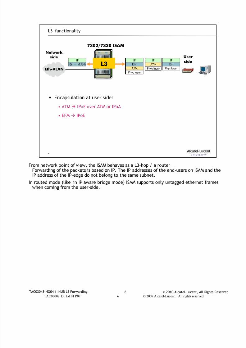
7/18/2019 Alu - A7302 Isam Fttu Operator Gpon Nant-e_ce-PDF
http://slidepdf.com/reader/full/alu-a7302-isam-fttu-operator-gpon-nant-ece-pdf 311/432
© 2010 Alcatel-Lucent, All Rights ReservedTAC03048-HO04 | IHUB L3 Forwarding 6
TAC03002_D_ Ed 01 P07 6 © 2009 Alcatel-Lucent., All rights reserved
6
L3 functionality
Network
side Userside
Eth-VLAN
7302/7330 ISAM
Phys layer
ATM
Eth
IP
Phys layer
ATM
IP
Eth – (VLAN)
IP
Phys layer
Eth
IP
L3
Encapsulation at user side:
• ATM IPoE over ATM or IPoA
• EFM IPoE
From network point of view, the ISAM behaves as a L3-hop / a router
Forwarding of the packets is based on IP. The IP addresses of the end-users on ISAM and theIP address of the IP-edge do not belong to the same subnet.
In routed mode (like in IP aware bridge mode) ISAM supports only untagged ethernet frameswhen coming from the user-side.
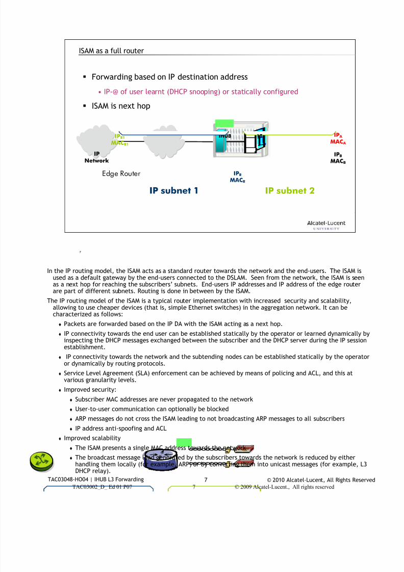
7/18/2019 Alu - A7302 Isam Fttu Operator Gpon Nant-e_ce-PDF
http://slidepdf.com/reader/full/alu-a7302-isam-fttu-operator-gpon-nant-ece-pdf 312/432
© 2010 Alcatel-Lucent, All Rights ReservedTAC03048-HO04 | IHUB L3 Forwarding 7
TAC03002_D_ Ed 01 P07 7 © 2009 Alcatel-Lucent., All rights reserved
7
ISAM as a full router
Forwarding based on IP destination address
• IP-@ of user learnt (DHCP snooping) or statically configured
ISAM is next hop
IPNetwork
IHUBIPR1
MACR1
LT
IPB
MACB
IP A
MAC A
Edge Router IPR
MACR
IP subnet 2IP subnet 1
In the IP routing model, the ISAM acts as a standard router towards the network and the end-users. The ISAM is
used as a default gateway by the end-users connected to the DSLAM. Seen from the network, the ISAM is seenas a next hop for reaching the subscribers’ subnets. End-users IP addresses and IP address of the edge routerare part of different subnets. Routing is done in between by the ISAM.
The IP routing model of the ISAM is a typical router implementation with increased security and scalability,allowing to use cheaper devices (that is, simple Ethernet switches) in the aggregation network. It can becharacterized as follows:
Packets are forwarded based on the IP DA with the ISAM acting as a next hop.
IP connectivity towards the end user can be established statically by the operator or learned dynamically byinspecting the DHCP messages exchanged between the subscriber and the DHCP server during the IP sessionestablishment.
IP connectivity towards the network and the subtending nodes can be established statically by the operatoror dynamically by routing protocols.
Service Level Agreement (SLA) enforcement can be achieved by means of policing and ACL, and this atvarious granularity levels.
Improved security:
Subscriber MAC addresses are never propagated to the network
User-to-user communication can optionally be blocked
ARP messages do not cross the ISAM leading to not broadcasting ARP messages to all subscribers
IP address anti-spoofing and ACL
Improved scalability
The ISAM presents a single MAC address towards the network
The broadcast message load generated by the subscribers towards the network is reduced by either
handling them locally (for example, ARP) or by converting them into unicast messages (for example, L3DHCP relay).
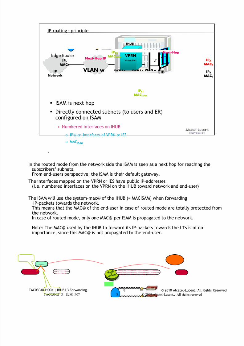
7/18/2019 Alu - A7302 Isam Fttu Operator Gpon Nant-e_ce-PDF
http://slidepdf.com/reader/full/alu-a7302-isam-fttu-operator-gpon-nant-ece-pdf 313/432
© 2010 Alcatel-Lucent, All Rights ReservedTAC03048-HO04 | IHUB L3 Forwarding 8
TAC03002_D_ Ed 01 P07 8 © 2009 Alcatel-Lucent., All rights reserved
8
IP routing - principle
ISAM is next hop
Directly connected subnets (to users and ER)configured on ISAM
• Numbered interfaces on IHUB
o IP@ on interfaces of VPRN or IES
o MACISAM
IPNetwork
IHUB
LT
IPB
MACB
IP A
MAC A
Edge Router VPRNNext-Hop IP
VLAN w EIB V-VPLS x
IPR1
MACISAM
IPR2
MACISAM
Next-Hop
IP x
MACx
V-VPLS x
Virtual Port
VLAN w
In the routed mode from the network side the ISAM is seen as a next hop for reaching the
subscribers’ subnets.From end-users perspective, the ISAM is their default gateway.
The interfaces mapped on the VPRN or IES have public IP-addresses(I.e. numbered interfaces on the VPRN on the IHUB toward network and end-user)
The ISAM will use the system-mac@ of the IHUB (= MACISAM) when forwardingIP-packets towards the network.This means that the MAC@ of the end-user in case of routed mode are totally protected fromthe network.In case of routed mode, only one MAC@ per ISAM is propagated to the network.
Note: The MAC@ used by the IHUB to forward its IP-packets towards the LTs is of noimportance, since this MAC@ is not propagated to the end-user.
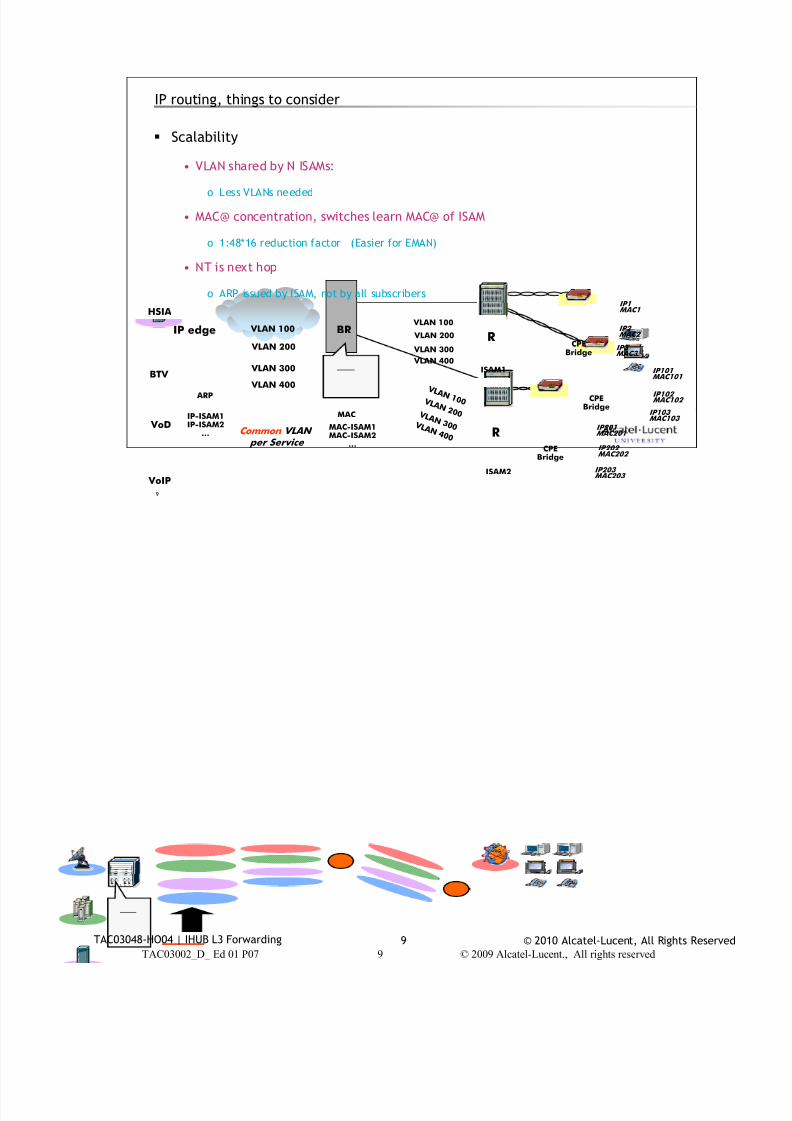
7/18/2019 Alu - A7302 Isam Fttu Operator Gpon Nant-e_ce-PDF
http://slidepdf.com/reader/full/alu-a7302-isam-fttu-operator-gpon-nant-ece-pdf 314/432
© 2010 Alcatel-Lucent, All Rights ReservedTAC03048-HO04 | IHUB L3 Forwarding 9
TAC03002_D_ Ed 01 P07 9 © 2009 Alcatel-Lucent., All rights reserved
9
IP routing, things to consider
Scalability
• VLAN shared by N ISAMs:
o Less VLANs needed
• MAC@ concentration, switches learn MAC@ of ISAM
o 1:48*16 reduction factor (Easier for EMAN)
• NT is next hop
o ARP issued by ISAM, not by all subscribers
ISAM1
ISAM2
CPEBridge
IP1 MAC1
IP2 MAC2
IP3 MAC3
IP101 MAC101
IP102 MAC102
IP103 MAC103
CPEBridge
CPEBridge
IP201 MAC201
IP202 MAC202
IP203 MAC203
BR
MAC
MAC-ISAM1MAC-ISAM2
…
IP edge
ARP
IP-ISAM1IP-ISAM2
…
HSIA
VoIP
BTV
VoD
VLAN 100
VLAN 200
VLAN 300
Common VLAN per Service
VLAN 400
VLAN 100
VLAN 200
VLAN 300
VLAN 400
V L A N 1 0 0 V L A N 2 0 0 V L A N 3 0 0 V L A N 4 0 0 R
R
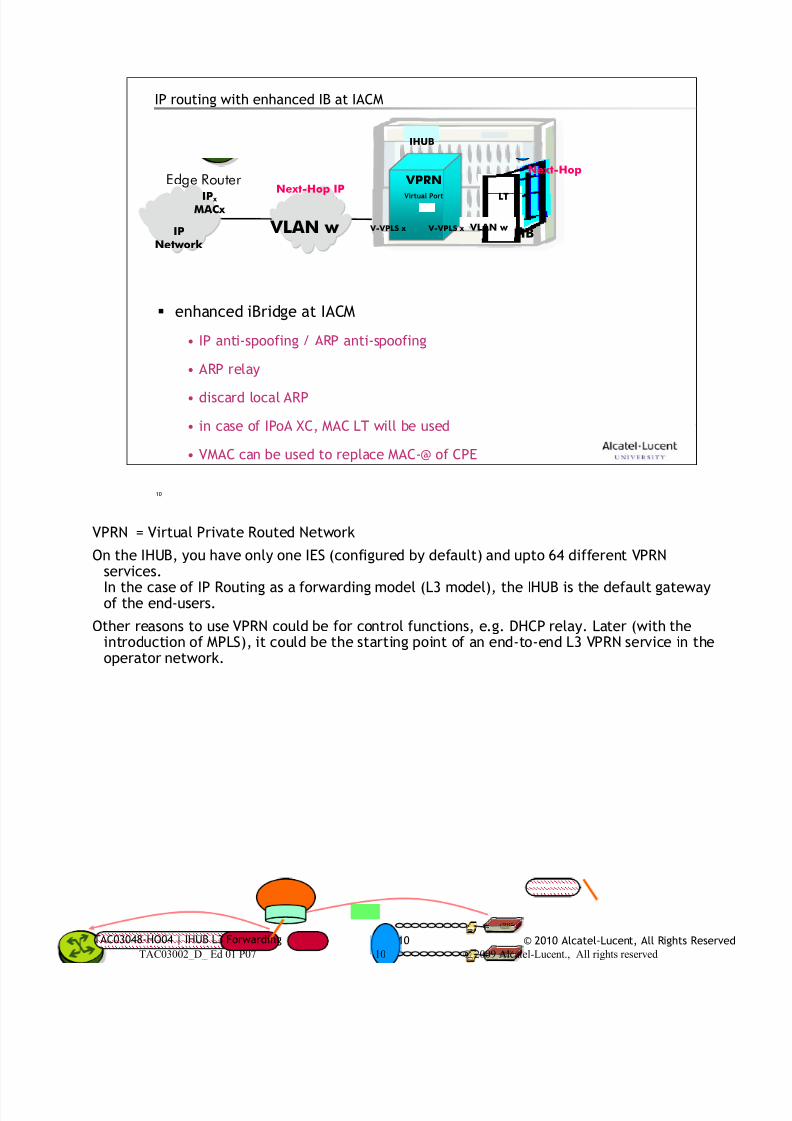
7/18/2019 Alu - A7302 Isam Fttu Operator Gpon Nant-e_ce-PDF
http://slidepdf.com/reader/full/alu-a7302-isam-fttu-operator-gpon-nant-ece-pdf 315/432
© 2010 Alcatel-Lucent, All Rights ReservedTAC03048-HO04 | IHUB L3 Forwarding 10
TAC03002_D_ Ed 01 P07 10 © 2009 Alcatel-Lucent., All rights reserved
10
IP routing with enhanced IB at IACM
enhanced iBridge at IACM
• IP anti-spoofing / ARP anti-spoofing
• ARP relay
• discard local ARP
• in case of IPoA XC, MAC LT will be used
• VMAC can be used to replace MAC-@ of CPE
IPNetwork
IHUB
LTEdge Router VPRNNext-Hop IP
VLAN w EIB V-VPLS x
Next-Hop
IP x
MACx
V-VPLS x
Virtual Port
VLAN w
VPRN = Virtual Private Routed Network
On the IHUB, you have only one IES (configured by default) and upto 64 different VPRNservices.In the case of IP Routing as a forwarding model (L3 model), the IHUB is the default gatewayof the end-users.
Other reasons to use VPRN could be for control functions, e.g. DHCP relay. Later (with theintroduction of MPLS), it could be the starting point of an end-to-end L3 VPRN service in theoperator network.
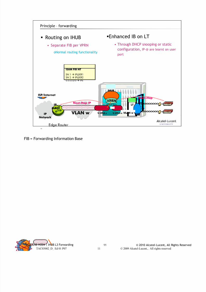
7/18/2019 Alu - A7302 Isam Fttu Operator Gpon Nant-e_ce-PDF
http://slidepdf.com/reader/full/alu-a7302-isam-fttu-operator-gpon-nant-ece-pdf 316/432
© 2010 Alcatel-Lucent, All Rights ReservedTAC03048-HO04 | IHUB L3 Forwarding 11
TAC03002_D_ Ed 01 P07 11 © 2009 Alcatel-Lucent., All rights reserved
11
Principle – forwarding
Routing on IHUB
• Separate FIB per VPRN
oNormal routing functionality
Enhanced IB on LT
• Through DHCP snooping or static
configuration, IP-@ are learnt on user
port
ISP/Internet
ISAM FIB NT
SN 1 IP@ER1SN 2 [email protected]/0 IPz
IPNetwork
IHUB
LT
VPRNNext-Hop IP
VLAN w EIB V-VPLS x
Next-Hop
IP x
MACx
V-VPLS x
Virtual Port
VLAN w
Edge Router
FIB = Forwarding Information Base
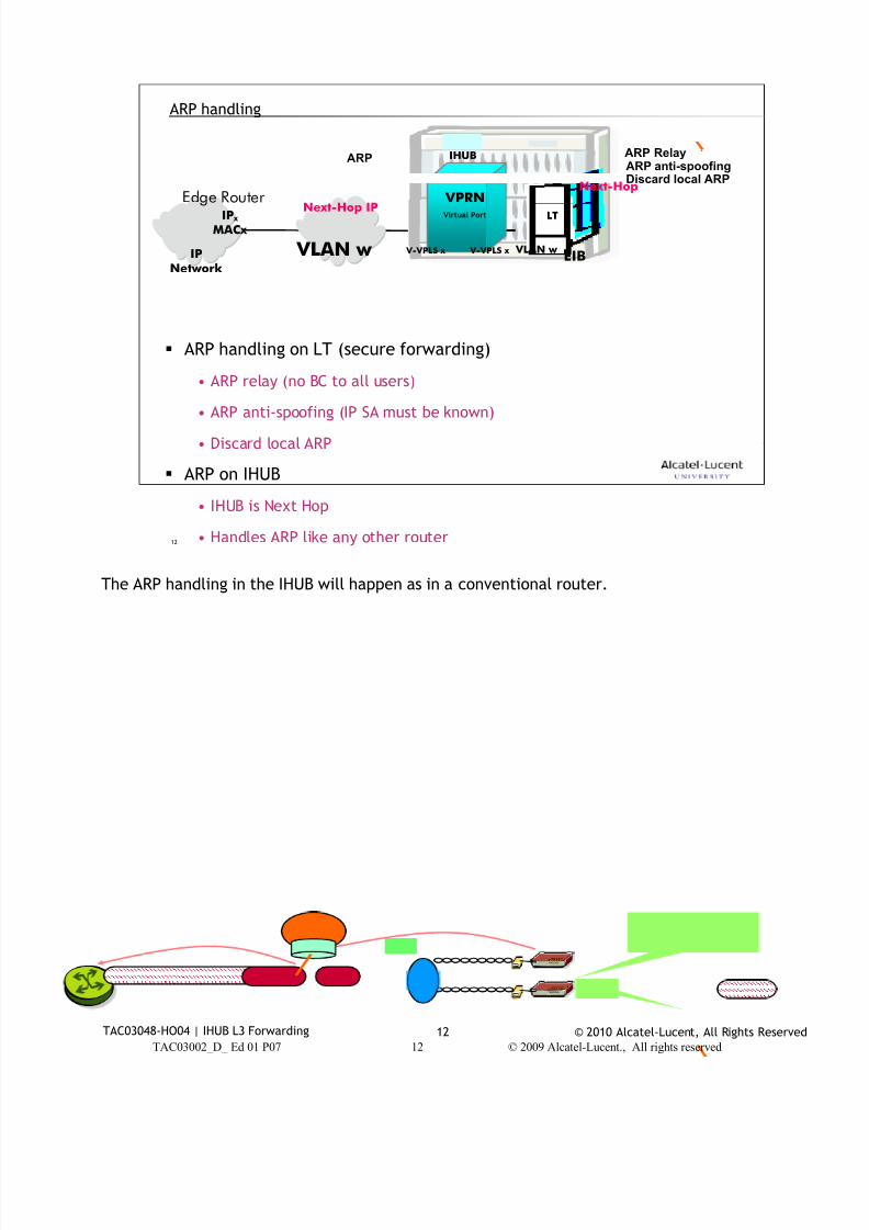
7/18/2019 Alu - A7302 Isam Fttu Operator Gpon Nant-e_ce-PDF
http://slidepdf.com/reader/full/alu-a7302-isam-fttu-operator-gpon-nant-ece-pdf 317/432
© 2010 Alcatel-Lucent, All Rights ReservedTAC03048-HO04 | IHUB L3 Forwarding 12
TAC03002_D_ Ed 01 P07 12 © 2009 Alcatel-Lucent., All rights reserved
12
ARP handling
ARP handling on LT (secure forwarding)
• ARP relay (no BC to all users)
• ARP anti-spoofing (IP SA must be known)
• Discard local ARP
ARP on IHUB
• IHUB is Next Hop
• Handles ARP like any other router
IPNetwork
IHUB
LTEdge Router VPRNNext-Hop IP
VLAN w EIB V-VPLS x
Next-Hop
IP x
MACx
V-VPLS x
Virtual Port
VLAN w
ARP RelayARP anti-spoofingDiscard local ARP
ARP
The ARP handling in the IHUB will happen as in a conventional router.

7/18/2019 Alu - A7302 Isam Fttu Operator Gpon Nant-e_ce-PDF
http://slidepdf.com/reader/full/alu-a7302-isam-fttu-operator-gpon-nant-ece-pdf 318/432
© 2010 Alcatel-Lucent, All Rights ReservedTAC03048-HO04 | IHUB L3 Forwarding 13
13
VPRN IHUB configuration2
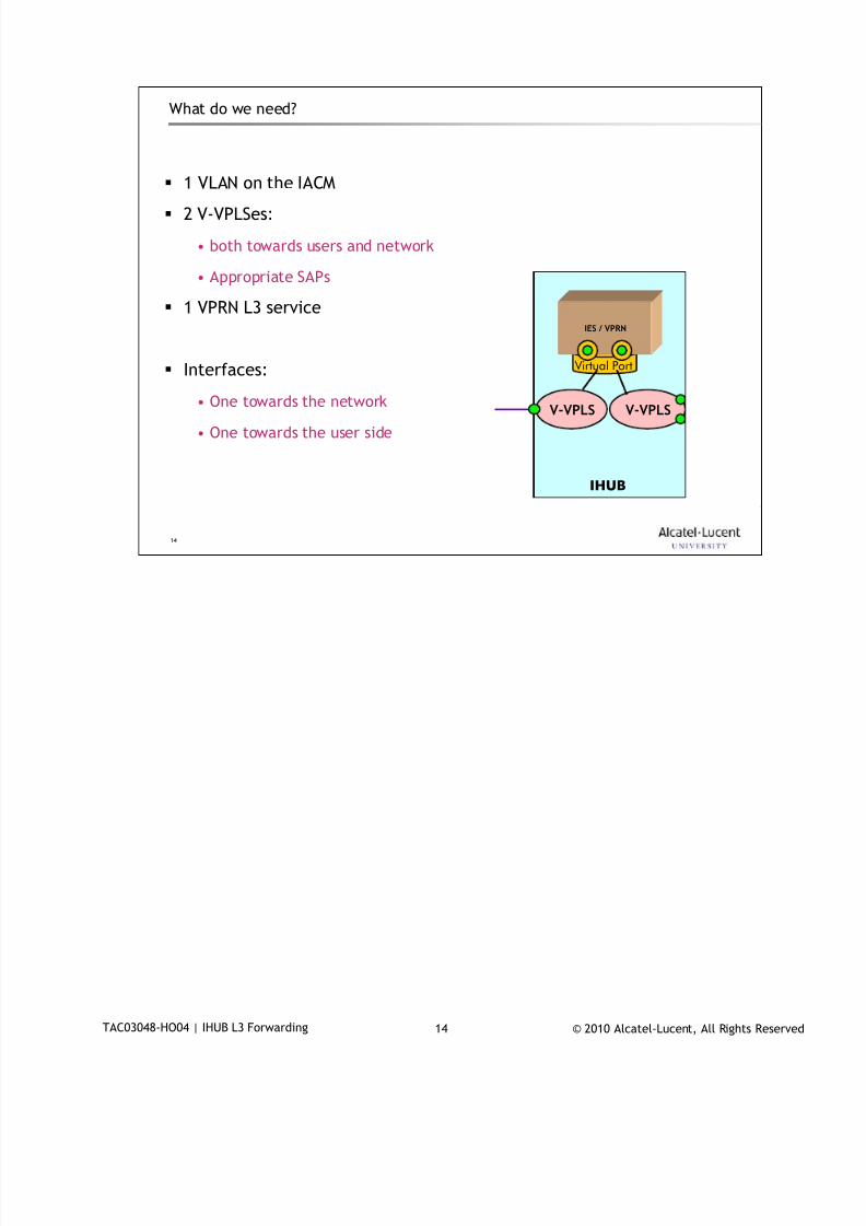
7/18/2019 Alu - A7302 Isam Fttu Operator Gpon Nant-e_ce-PDF
http://slidepdf.com/reader/full/alu-a7302-isam-fttu-operator-gpon-nant-ece-pdf 319/432
© 2010 Alcatel-Lucent, All Rights ReservedTAC03048-HO04 | IHUB L3 Forwarding 14
14
What do we need?
1 VLAN on the IACM
2 V-VPLSes:
• both towards users and network
• Appropriate SAPs
1 VPRN L3 service
Interfaces:
• One towards the network
• One towards the user side
IHUB
IES / VPRN
Virtual Port
V-VPLSV-VPLS
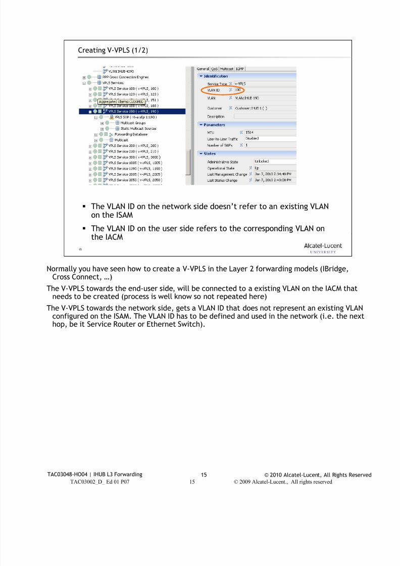
7/18/2019 Alu - A7302 Isam Fttu Operator Gpon Nant-e_ce-PDF
http://slidepdf.com/reader/full/alu-a7302-isam-fttu-operator-gpon-nant-ece-pdf 320/432
© 2010 Alcatel-Lucent, All Rights ReservedTAC03048-HO04 | IHUB L3 Forwarding 15
TAC03002_D_ Ed 01 P07 15 © 2009 Alcatel-Lucent., All rights reserved
15
Creating V-VPLS (1/2)
The VLAN ID on the network side doesn’t refer to an existing VLANon the ISAM
The VLAN ID on the user side refers to the corresponding VLAN onthe IACM
Normally you have seen how to create a V-VPLS in the Layer 2 forwarding models (IBridge,
Cross Connect, …)
The V-VPLS towards the end-user side, will be connected to a existing VLAN on the IACM thatneeds to be created (process is well know so not repeated here)
The V-VPLS towards the network side, gets a VLAN ID that does not represent an existing VLANconfigured on the ISAM. The VLAN ID has to be defined and used in the network (i.e. the nexthop, be it Service Router or Ethernet Switch).
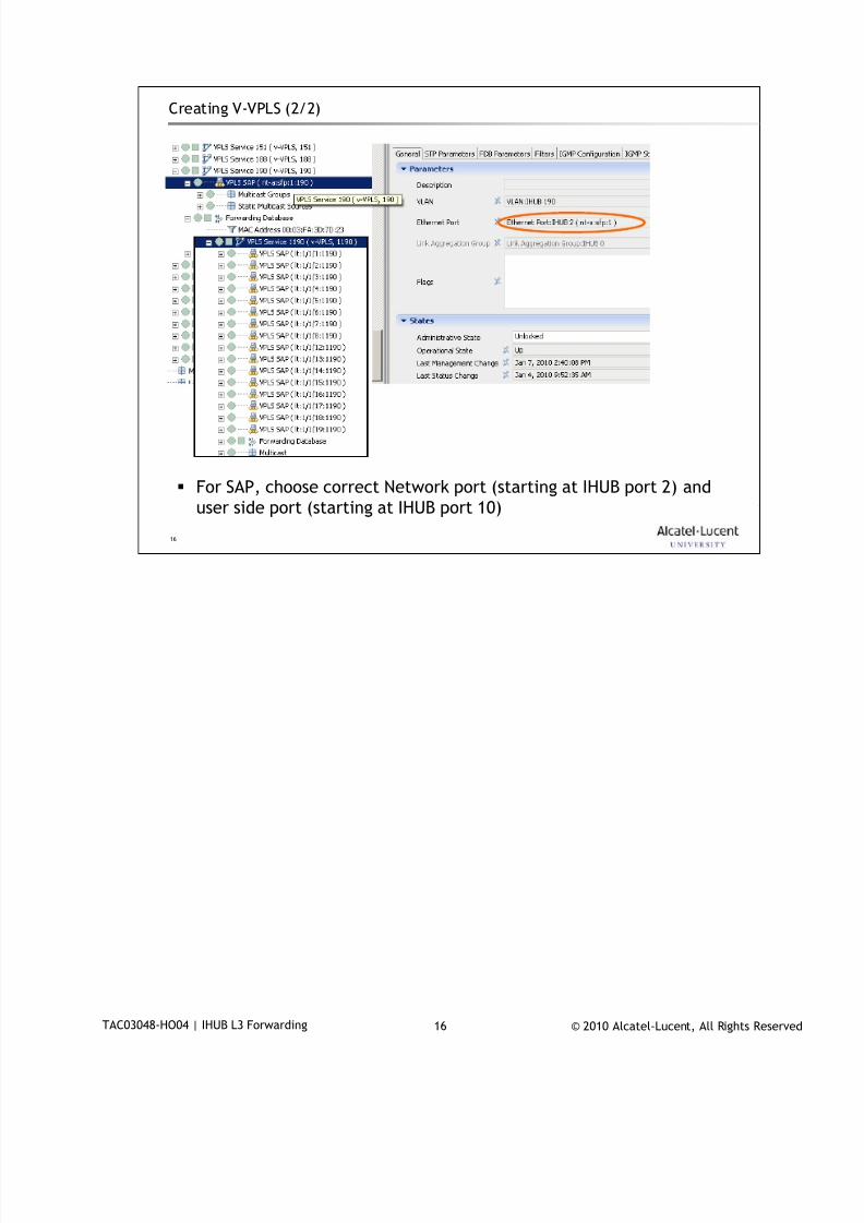
7/18/2019 Alu - A7302 Isam Fttu Operator Gpon Nant-e_ce-PDF
http://slidepdf.com/reader/full/alu-a7302-isam-fttu-operator-gpon-nant-ece-pdf 321/432
© 2010 Alcatel-Lucent, All Rights ReservedTAC03048-HO04 | IHUB L3 Forwarding 16
16
Creating V-VPLS (2/2)
For SAP, choose correct Network port (starting at IHUB port 2) and
user side port (starting at IHUB port 10)
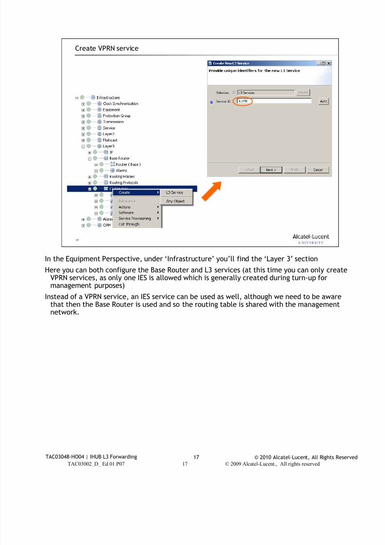
7/18/2019 Alu - A7302 Isam Fttu Operator Gpon Nant-e_ce-PDF
http://slidepdf.com/reader/full/alu-a7302-isam-fttu-operator-gpon-nant-ece-pdf 322/432
© 2010 Alcatel-Lucent, All Rights ReservedTAC03048-HO04 | IHUB L3 Forwarding 17
TAC03002_D_ Ed 01 P07 17 © 2009 Alcatel-Lucent., All rights reserved
17
Create VPRN service
In the Equipment Perspective, under ‘Infrastructure’ you’ll find the ‘Layer 3’ section
Here you can both configure the Base Router and L3 services (at this time you can only createVPRN services, as only one IES is allowed which is generally created during turn-up formanagement purposes)
Instead of a VPRN service, an IES service can be used as well, although we need to be awarethat then the Base Router is used and so the routing table is shared with the managementnetwork.
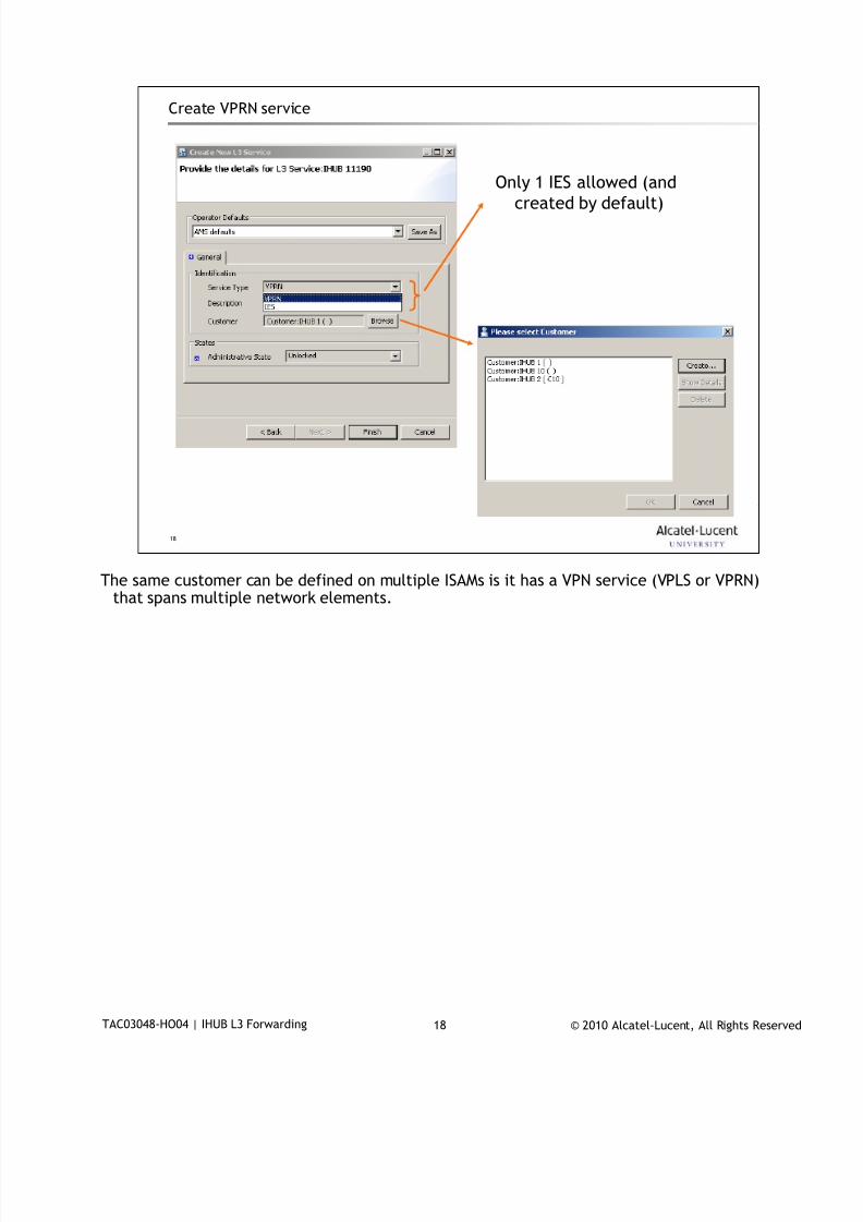
7/18/2019 Alu - A7302 Isam Fttu Operator Gpon Nant-e_ce-PDF
http://slidepdf.com/reader/full/alu-a7302-isam-fttu-operator-gpon-nant-ece-pdf 323/432
© 2010 Alcatel-Lucent, All Rights ReservedTAC03048-HO04 | IHUB L3 Forwarding 18
18
Create VPRN service
Only 1 IES allowed (and
created by default)
The same customer can be defined on multiple ISAMs is it has a VPN service (VPLS or VPRN)
that spans multiple network elements.
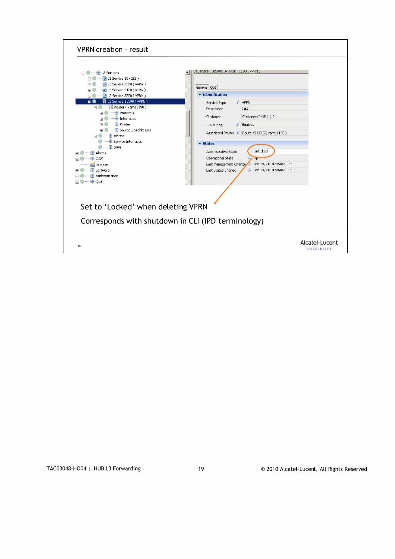
7/18/2019 Alu - A7302 Isam Fttu Operator Gpon Nant-e_ce-PDF
http://slidepdf.com/reader/full/alu-a7302-isam-fttu-operator-gpon-nant-ece-pdf 324/432
© 2010 Alcatel-Lucent, All Rights ReservedTAC03048-HO04 | IHUB L3 Forwarding 19
19
VPRN creation - result
Set to ‘Locked’ when deleting VPRN
Corresponds with shutdown in CLI (IPD terminology)
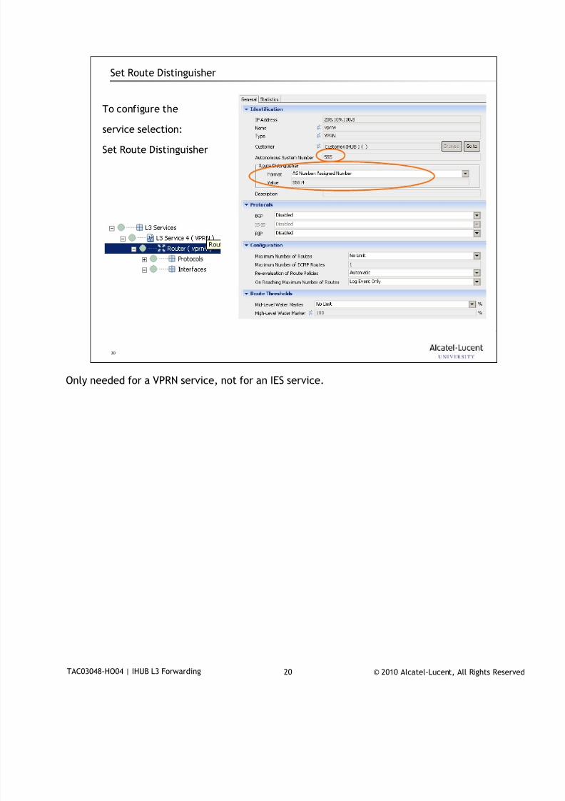
7/18/2019 Alu - A7302 Isam Fttu Operator Gpon Nant-e_ce-PDF
http://slidepdf.com/reader/full/alu-a7302-isam-fttu-operator-gpon-nant-ece-pdf 325/432
© 2010 Alcatel-Lucent, All Rights ReservedTAC03048-HO04 | IHUB L3 Forwarding 20
20
Set Route Distinguisher
To configure the
service selection:
Set Route Distinguisher
Only needed for a VPRN service, not for an IES service.
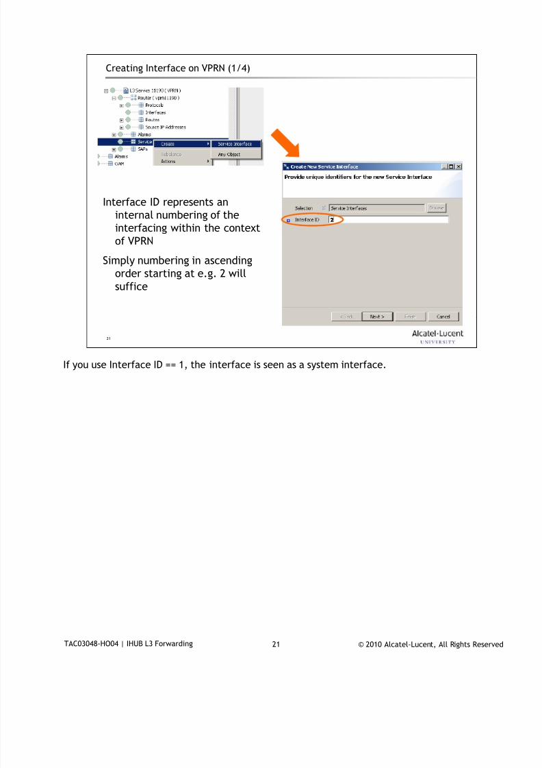
7/18/2019 Alu - A7302 Isam Fttu Operator Gpon Nant-e_ce-PDF
http://slidepdf.com/reader/full/alu-a7302-isam-fttu-operator-gpon-nant-ece-pdf 326/432
© 2010 Alcatel-Lucent, All Rights ReservedTAC03048-HO04 | IHUB L3 Forwarding 21
21
Creating Interface on VPRN (1/4)
Interface ID represents an
internal numbering of the
interfacing within the context
of VPRN
Simply numbering in ascending
order starting at e.g. 2 will
suffice
2
If you use Interface ID == 1, the interface is seen as a system interface.
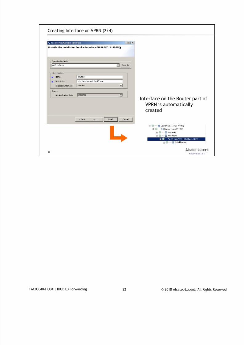
7/18/2019 Alu - A7302 Isam Fttu Operator Gpon Nant-e_ce-PDF
http://slidepdf.com/reader/full/alu-a7302-isam-fttu-operator-gpon-nant-ece-pdf 327/432
© 2010 Alcatel-Lucent, All Rights ReservedTAC03048-HO04 | IHUB L3 Forwarding 22
22
Creating Interface on VPRN (2/4)
Interface on the Router part of
VPRN is automatically
created
2
2
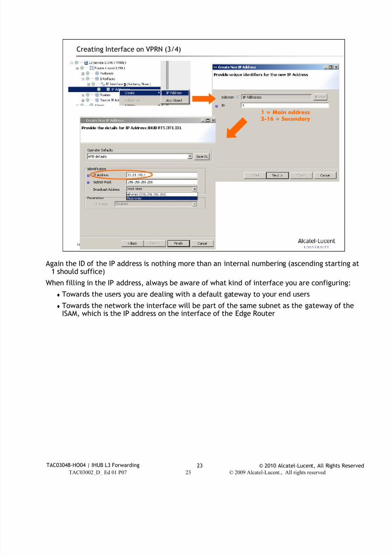
7/18/2019 Alu - A7302 Isam Fttu Operator Gpon Nant-e_ce-PDF
http://slidepdf.com/reader/full/alu-a7302-isam-fttu-operator-gpon-nant-ece-pdf 328/432
© 2010 Alcatel-Lucent, All Rights ReservedTAC03048-HO04 | IHUB L3 Forwarding 23
TAC03002_D_ Ed 01 P07 23 © 2009 Alcatel-Lucent., All rights reserved
23
Creating Interface on VPRN (3/4)
1 = Main address2-16 = Secondary
2
Again the ID of the IP address is nothing more than an internal numbering (ascending starting at
1 should suffice)
When filling in the IP address, always be aware of what kind of interface you are configuring:
Towards the users you are dealing with a default gateway to your end users
Towards the network the interface will be part of the same subnet as the gateway of theISAM, which is the IP address on the interface of the Edge Router
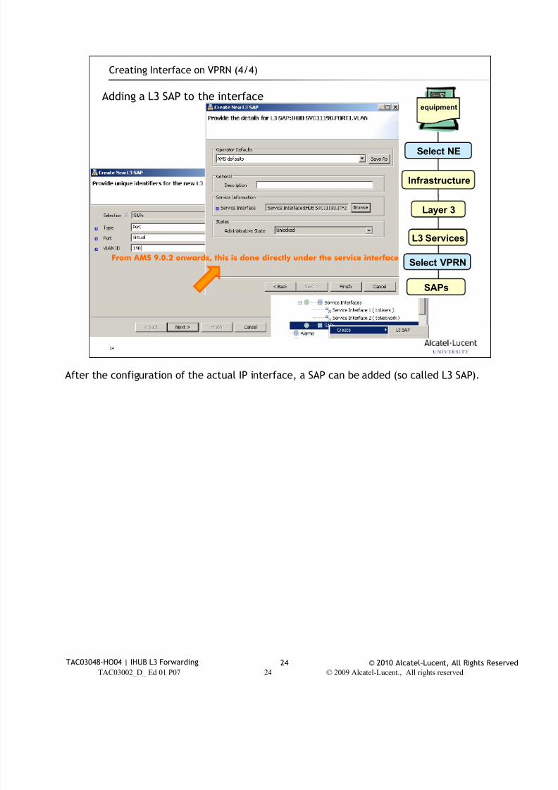
7/18/2019 Alu - A7302 Isam Fttu Operator Gpon Nant-e_ce-PDF
http://slidepdf.com/reader/full/alu-a7302-isam-fttu-operator-gpon-nant-ece-pdf 329/432
© 2010 Alcatel-Lucent, All Rights ReservedTAC03048-HO04 | IHUB L3 Forwarding 24
24
Creating Interface on VPRN (4/4)
Adding a L3 SAP to the interfaceequipment
Select NE
Infrastructure
Layer 3
L3 Services
Select VPRN
SAPs
From AMS 9.0.2 onwards, this is done directly under the service interface
After the configuration of the actual IP interface, a SAP can be added (so called L3 SAP).
TAC03002_D_ Ed 01 P07 24 © 2009 Alcatel-Lucent., All rights reserved
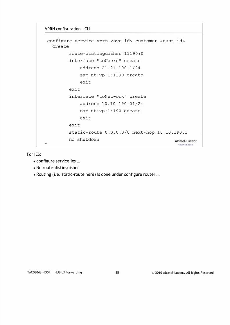
7/18/2019 Alu - A7302 Isam Fttu Operator Gpon Nant-e_ce-PDF
http://slidepdf.com/reader/full/alu-a7302-isam-fttu-operator-gpon-nant-ece-pdf 330/432
© 2010 Alcatel-Lucent, All Rights ReservedTAC03048-HO04 | IHUB L3 Forwarding 25
25
VPRN configuration - CLI
configure service vprn <svc-id> customer <cust-id>
create
route-distinguisher 11190:0
interface "toUsers" create
address 21.21.190.1/24
sap nt:vp:1:1190 create
exit
exit
interface "toNetwork" create
address 10.10.190.21/24sap nt:vp:1:190 create
exit
exit
static-route 0.0.0.0/0 next-hop 10.10.190.1
no shutdown
For IES:
configure service ies …
No route-distinguisher
Routing (i.e. static-route here) is done under configure router …

7/18/2019 Alu - A7302 Isam Fttu Operator Gpon Nant-e_ce-PDF
http://slidepdf.com/reader/full/alu-a7302-isam-fttu-operator-gpon-nant-ece-pdf 331/432
© 2010 Alcatel-Lucent, All Rights ReservedTAC03048-HO04 | IHUB L3 Forwarding 26
26
DHCP Relay IHUB configuration3
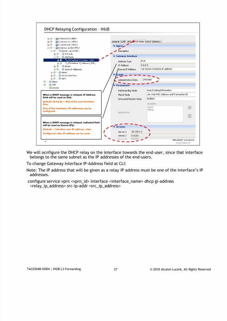
7/18/2019 Alu - A7302 Isam Fttu Operator Gpon Nant-e_ce-PDF
http://slidepdf.com/reader/full/alu-a7302-isam-fttu-operator-gpon-nant-ece-pdf 332/432
© 2010 Alcatel-Lucent, All Rights ReservedTAC03048-HO04 | IHUB L3 Forwarding 27
27
DHCP Relaying Configuration – IHUB
When a DHCP message is relayed, IP Addressfield will be used as Gi@.
Default: (0.0.0.0) = IP@ of the user interface.
Else:
One of the interface’s IP addresses can beconfigured
When a DHCP message is relayed, indicated field will be used as Source-IP@.
Default: = Interface own IP address , else:
Configured relay IP address can be used.
We will ocnfigure the DHCP relay on the interface towards the end-user, since that interface
belongs to the same subnet as the IP addresses of the end-users.
To change Gateway Interface IP-Address field at CLI:
Note: The IP address that will be given as a relay IP address must be one of the interface’s IPaddresses.
configure service vprn <vprn_id> interface <interface_name> dhcp gi-address<relay_ip_address> src-ip-addr <src_ip_address>
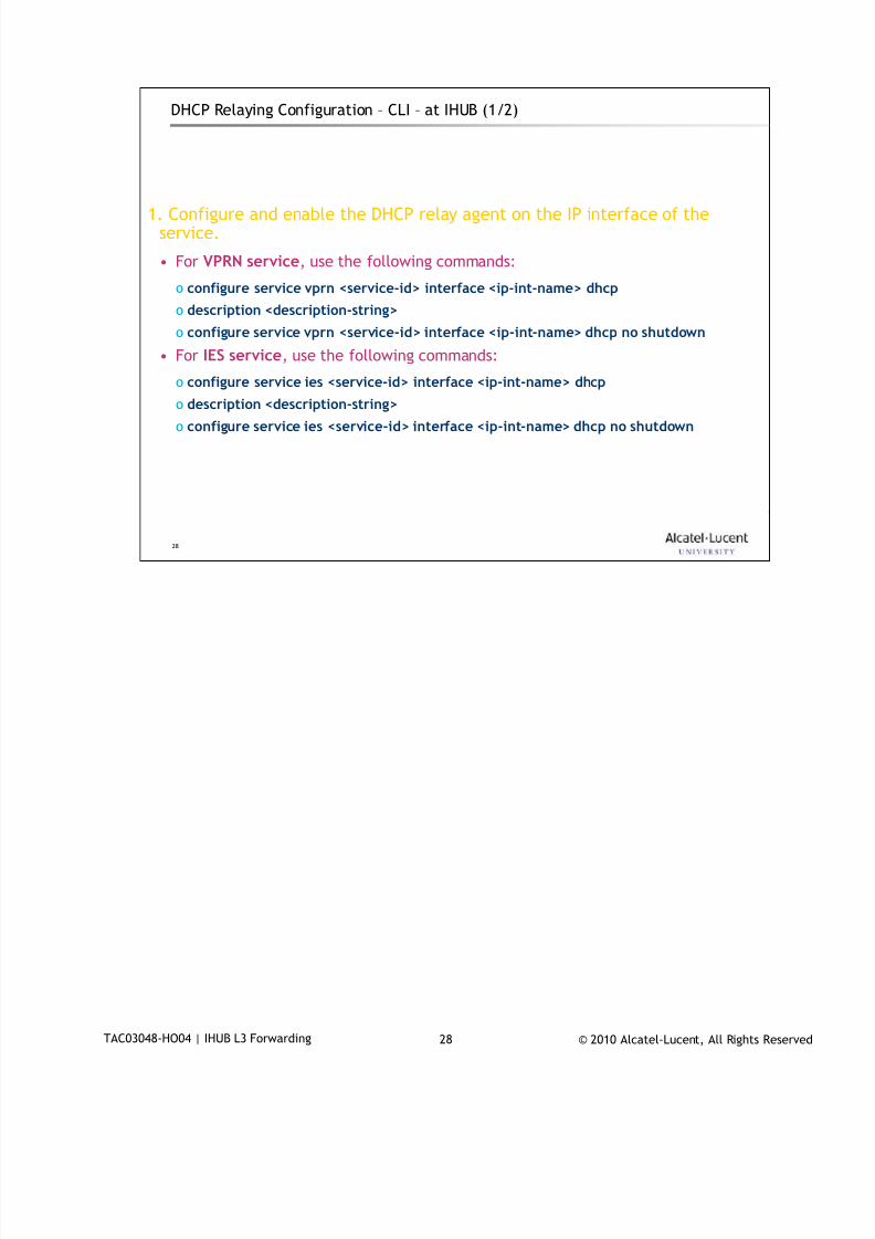
7/18/2019 Alu - A7302 Isam Fttu Operator Gpon Nant-e_ce-PDF
http://slidepdf.com/reader/full/alu-a7302-isam-fttu-operator-gpon-nant-ece-pdf 333/432
© 2010 Alcatel-Lucent, All Rights ReservedTAC03048-HO04 | IHUB L3 Forwarding 28
28
1. Configure and enable the DHCP relay agent on the IP interface of theservice.
• For VPRN service, use the following commands:
o configure service vprn <service-id> interface <ip-int-name> dhcp
o description <description-string>
o configure service vprn <service-id> interface <ip-int-name> dhcp no shutdown
• For IES service, use the following commands:
o configure service ies <service-id> interface <ip-int-name> dhcp
o description <description-string>
o configure service ies <service-id> interface <ip-int-name> dhcp no shutdown
DHCP Relaying Configuration – CLI – at IHUB (1/2)
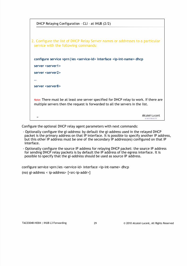
7/18/2019 Alu - A7302 Isam Fttu Operator Gpon Nant-e_ce-PDF
http://slidepdf.com/reader/full/alu-a7302-isam-fttu-operator-gpon-nant-ece-pdf 334/432
© 2010 Alcatel-Lucent, All Rights ReservedTAC03048-HO04 | IHUB L3 Forwarding 29
29
2. Configure the list of DHCP Relay Server names or addresses to a particular
service with the following commands:
configure service vprn|ies <service-id> interface <ip-int-name> dhcp
server <server1>
server <server2>
…
server <server8>
Note: There must be at least one server specified for DHCP relay to work. If there are
multiple servers then the request is forwarded to all the servers in the list.
DHCP Relaying Configuration – CLI – at IHUB (2/2)
Configure the optional DHCP relay agent parameters with next commands:
- Optionally configure the gi-address: by default the gi-address used in the relayed DHCPpacket is the primary address on that IP interface. It is possible to specify another IP address,but this other IP address must be one of the secondary IP address(es) configured on that IPinterface.
- Optionally configure the source IP address for relaying DHCP packet: the source IP addressfor sending DHCP relay packets is by default the IP address of the egress interface. It ispossible to specify that the gi-address should be used as source IP address.
configure service vprn|ies <service-id> interface <ip-int-name> dhcp
(no) gi-address < ip-address> [<src-ip-addr>]
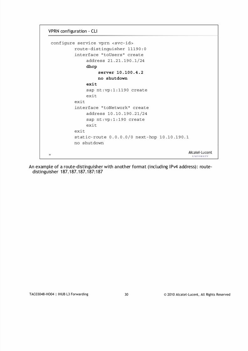
7/18/2019 Alu - A7302 Isam Fttu Operator Gpon Nant-e_ce-PDF
http://slidepdf.com/reader/full/alu-a7302-isam-fttu-operator-gpon-nant-ece-pdf 335/432
© 2010 Alcatel-Lucent, All Rights ReservedTAC03048-HO04 | IHUB L3 Forwarding 30
30
VPRN configuration - CLI
configure service vprn <svc-id>
route-distinguisher 11190:0
interface "toUsers" create
address 21.21.190.1/24
dhcp
server 10.100.4.2
no shutdown
exit
sap nt:vp:1:1190 create
exit
exit
interface "toNetwork" create
address 10.10.190.21/24sap nt:vp:1:190 create
exit
exit
static-route 0.0.0.0/0 next-hop 10.10.190.1
no shutdown
An example of a route-distinguisher with another format (including IPv4 address): route-
distinguisher 187.187.187.187:187

7/18/2019 Alu - A7302 Isam Fttu Operator Gpon Nant-e_ce-PDF
http://slidepdf.com/reader/full/alu-a7302-isam-fttu-operator-gpon-nant-ece-pdf 336/432
© 2010 Alcatel-Lucent, All Rights ReservedTAC03048-HO04 | IHUB L3 Forwarding 31
31
IP Routing –
IS-IS Protocol IHUB configuration4
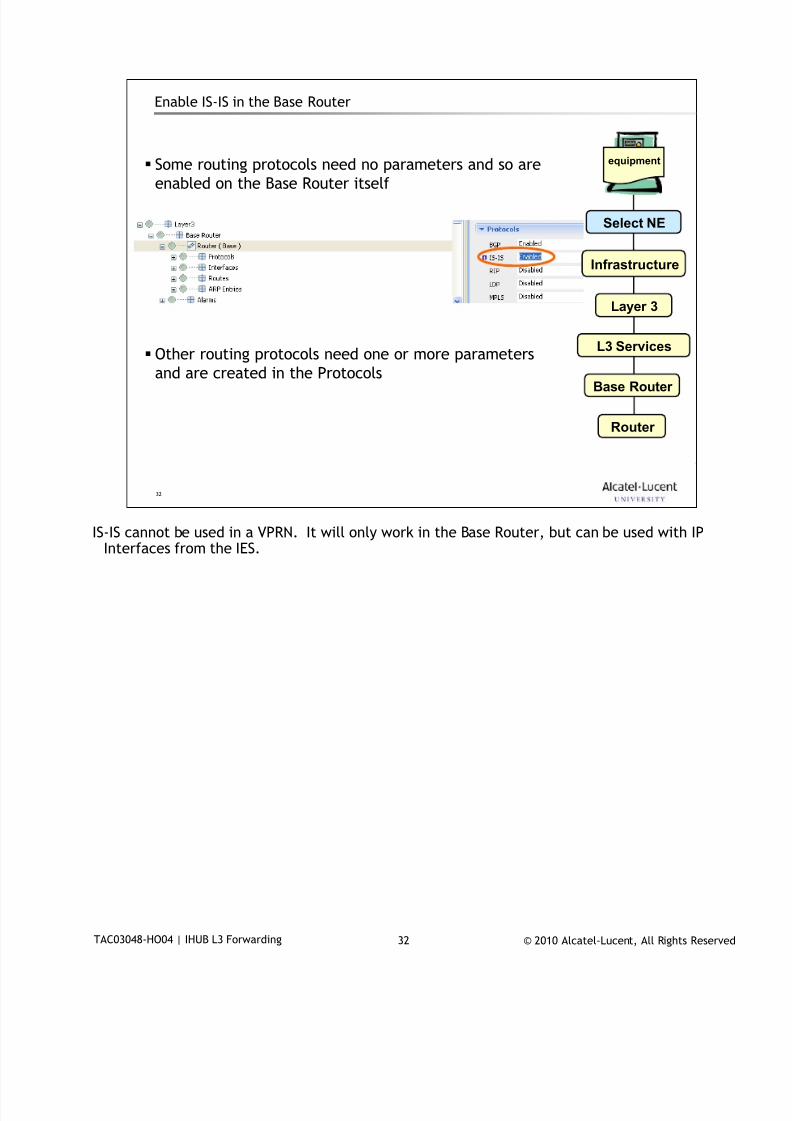
7/18/2019 Alu - A7302 Isam Fttu Operator Gpon Nant-e_ce-PDF
http://slidepdf.com/reader/full/alu-a7302-isam-fttu-operator-gpon-nant-ece-pdf 337/432
© 2010 Alcatel-Lucent, All Rights ReservedTAC03048-HO04 | IHUB L3 Forwarding 32
32
Enable IS-IS in the Base Router
Some routing protocols need no parameters and so are
enabled on the Base Router itself
Other routing protocols need one or more parameters
and are created in the Protocols
equipment
Select NE
Infrastructure
Layer 3
L3 Services
Router
Base Router
IS-IS cannot be used in a VPRN. It will only work in the Base Router, but can be used with IP
Interfaces from the IES.
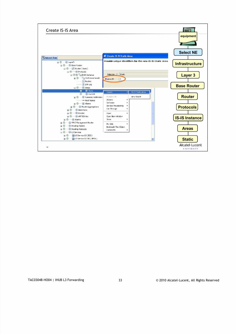
7/18/2019 Alu - A7302 Isam Fttu Operator Gpon Nant-e_ce-PDF
http://slidepdf.com/reader/full/alu-a7302-isam-fttu-operator-gpon-nant-ece-pdf 338/432
© 2010 Alcatel-Lucent, All Rights ReservedTAC03048-HO04 | IHUB L3 Forwarding 33
33
Create IS-IS Area
equipment
Select NE
Infrastructure
Layer 3
Base Router
Router
Protocols
IS-IS Instance
Areas
Static
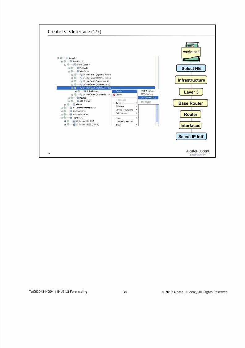
7/18/2019 Alu - A7302 Isam Fttu Operator Gpon Nant-e_ce-PDF
http://slidepdf.com/reader/full/alu-a7302-isam-fttu-operator-gpon-nant-ece-pdf 339/432
© 2010 Alcatel-Lucent, All Rights ReservedTAC03048-HO04 | IHUB L3 Forwarding 34
34
Create IS-IS Interface (1/2)
equipment
Select NE
Infrastructure
Layer 3
Base Router
Router
Interfaces
Select IP Intf.
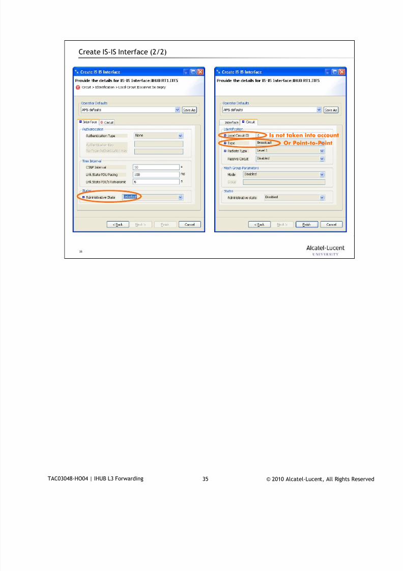
7/18/2019 Alu - A7302 Isam Fttu Operator Gpon Nant-e_ce-PDF
http://slidepdf.com/reader/full/alu-a7302-isam-fttu-operator-gpon-nant-ece-pdf 340/432
© 2010 Alcatel-Lucent, All Rights ReservedTAC03048-HO04 | IHUB L3 Forwarding 35
35
Create IS-IS Interface (2/2)
Is not taken into account
Or Point-to-Point

7/18/2019 Alu - A7302 Isam Fttu Operator Gpon Nant-e_ce-PDF
http://slidepdf.com/reader/full/alu-a7302-isam-fttu-operator-gpon-nant-ece-pdf 341/432
© 2010 Alcatel-Lucent, All Rights ReservedTAC03048-HO04 | IHUB L3 Forwarding 36
36
IES and Base Router configuration - CLI
configure service ies <svc-id>
interface "toUsers" create
address 21.21.190.1/24
dhcp
server 10.100.4.2
no shutdown
exit
sap nt:vp:1:1190 create
exit
exit
interface "toNetwork" create
address 10.10.190.21/24
sap nt:vp:1:190 create
exit
exit
no shutdown
configure router
isis
area-id 00
interface "toNetwork"
interface-type broadcast
exit
exit
Only IES service supports IS-IS through the Base Router.

7/18/2019 Alu - A7302 Isam Fttu Operator Gpon Nant-e_ce-PDF
http://slidepdf.com/reader/full/alu-a7302-isam-fttu-operator-gpon-nant-ece-pdf 342/432
© 2010 Alcatel-Lucent, All Rights ReservedTAC03048-HO04 | IHUB L3 Forwarding 37
37
IP / MAC Filters5
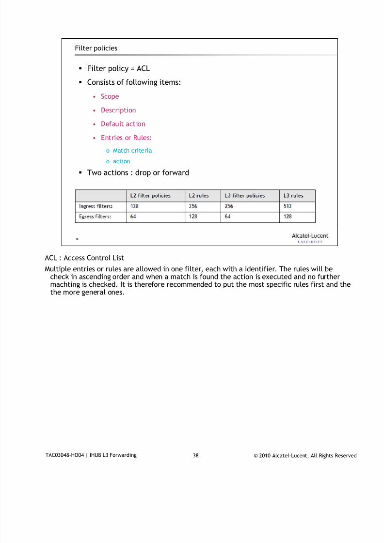
7/18/2019 Alu - A7302 Isam Fttu Operator Gpon Nant-e_ce-PDF
http://slidepdf.com/reader/full/alu-a7302-isam-fttu-operator-gpon-nant-ece-pdf 343/432
© 2010 Alcatel-Lucent, All Rights ReservedTAC03048-HO04 | IHUB L3 Forwarding 38
38
Filter policies
Filter policy = ACL
Consists of following items:
• Scope
• Description
• Default action
• Entries or Rules:
o Match criteria
o action
Two actions : drop or forward
ACL : Access Control List
Multiple entries or rules are allowed in one filter, each with a identifier. The rules will becheck in ascending order and when a match is found the action is executed and no furthermachting is checked. It is therefore recommended to put the most specific rules first and thethe more general ones.
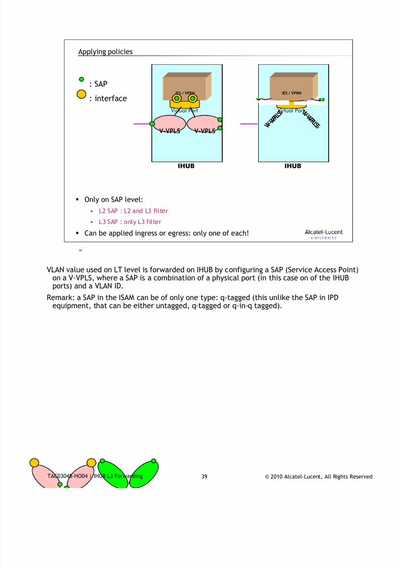
7/18/2019 Alu - A7302 Isam Fttu Operator Gpon Nant-e_ce-PDF
http://slidepdf.com/reader/full/alu-a7302-isam-fttu-operator-gpon-nant-ece-pdf 344/432
© 2010 Alcatel-Lucent, All Rights ReservedTAC03048-HO04 | IHUB L3 Forwarding 39
39
Applying policies
: SAP
: interface
IHUB
IES / VPRN
Virtual Port
V-VPLSV-VPLS
Only on SAP level:
• L2 SAP : L2 and L3 filter
• L3 SAP : only L3 filter
Can be applied ingress or egress: only one of each!
IHUB
IES / VPRN
Virtual PortV - V P L S V - V P
L S
V - V P
L S V
- V P L S
VLAN value used on LT level is forwarded on IHUB by configuring a SAP (Service Access Point)
on a V-VPLS, where a SAP is a combination of a physical port (in this case on of the IHUBports) and a VLAN ID.
Remark: a SAP in the ISAM can be of only one type: q-tagged (this unlike the SAP in IPDequipment, that can be either untagged, q-tagged or q-in-q tagged).
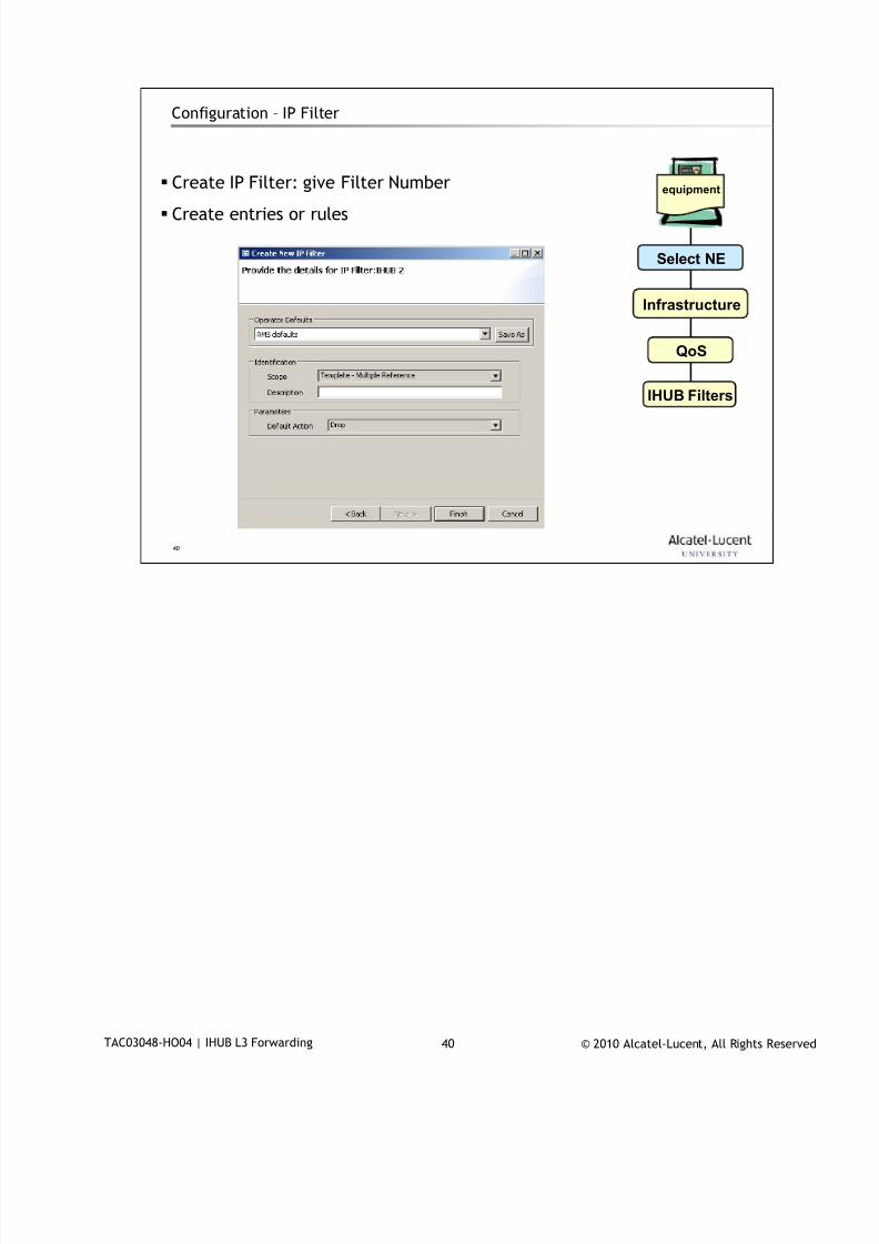
7/18/2019 Alu - A7302 Isam Fttu Operator Gpon Nant-e_ce-PDF
http://slidepdf.com/reader/full/alu-a7302-isam-fttu-operator-gpon-nant-ece-pdf 345/432
© 2010 Alcatel-Lucent, All Rights ReservedTAC03048-HO04 | IHUB L3 Forwarding 40
40
Configuration – IP Filter
Create IP Filter: give Filter Number
Create entries or rules
equipment
Select NE
Infrastructure
QoS
IHUB Filters
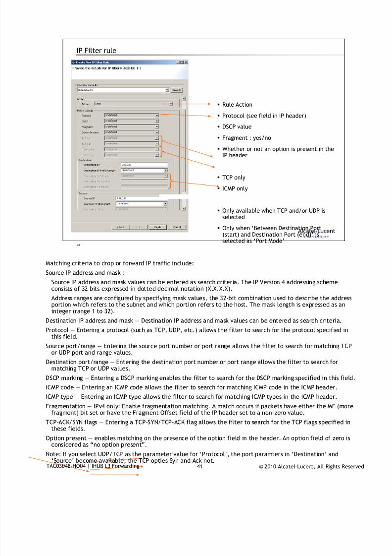
7/18/2019 Alu - A7302 Isam Fttu Operator Gpon Nant-e_ce-PDF
http://slidepdf.com/reader/full/alu-a7302-isam-fttu-operator-gpon-nant-ece-pdf 346/432
© 2010 Alcatel-Lucent, All Rights ReservedTAC03048-HO04 | IHUB L3 Forwarding 41
41
IP Filter rule
Rule Action
Protocol (see field in IP header)
DSCP value
Fragment : yes/no
Whether or not an option is present in theIP header
TCP only
ICMP only
Only available when TCP and/or UDP isselected
Only when ‘Between Destination Port(start) and Destination Port (end)’ isselected as ‘Port Mode’
Matching criteria to drop or forward IP traffic include:
Source IP address and mask :
Source IP address and mask values can be entered as search criteria. The IP Version 4 addressing schemeconsists of 32 bits expressed in dotted decimal notation (X.X.X.X).
Address ranges are configured by specifying mask values, the 32-bit combination used to describe the addressportion which refers to the subnet and which portion refers to the host. The mask length is expressed as aninteger (range 1 to 32).
Destination IP address and mask — Destination IP address and mask values can be entered as search criteria.
Protocol — Entering a protocol (such as TCP, UDP, etc.) allows the filter to search for the protocol specified inthis field.
Source port/range — Entering the source port number or port range allows the filter to search for matching TCPor UDP port and range values.
Destination port/range — Entering the destination port number or port range allows the filter to search formatching TCP or UDP values.
DSCP marking — Entering a DSCP marking enables the filter to search for the DSCP marking specified in this field.
ICMP code — Entering an ICMP code allows the filter to search for matching ICMP code in the ICMP header.
ICMP type — Entering an ICMP type allows the filter to search for matching ICMP types in the ICMP header.
Fragmentation — IPv4 only: Enable fragmentation matching. A match occurs if packets have either the MF (morefragment) bit set or have the Fragment Offset field of the IP header set to a non-zero value.
TCP-ACK/SYN flags — Entering a TCP-SYN/TCP-ACK flag allows the filter to search for the TCP flags specified inthese fields.
Option present — enables matching on the presence of the option field in the header. An option field of zero isconsidered as “no option present”.
Note: If you select UDP/TCP as the parameter value for ‘Protocol’, the port paramters in ‘Destination’ and‘Source’ become available, the TCP opties Syn and Ack not.
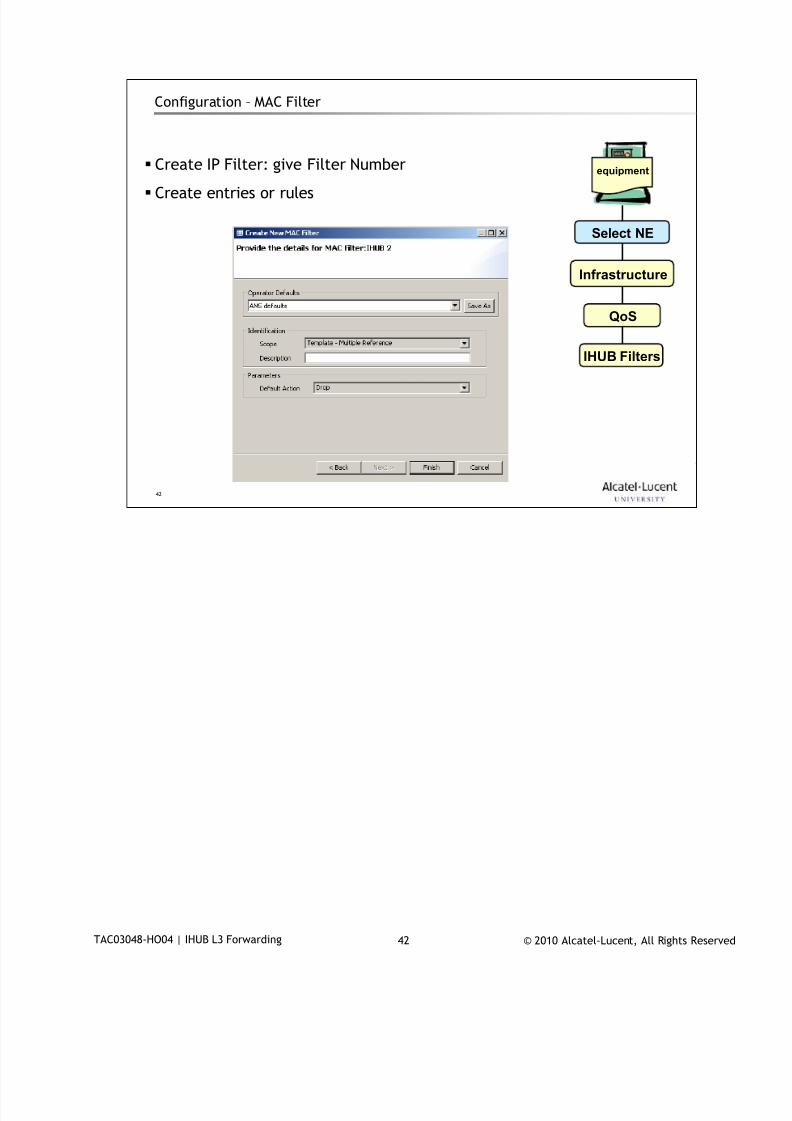
7/18/2019 Alu - A7302 Isam Fttu Operator Gpon Nant-e_ce-PDF
http://slidepdf.com/reader/full/alu-a7302-isam-fttu-operator-gpon-nant-ece-pdf 347/432
© 2010 Alcatel-Lucent, All Rights ReservedTAC03048-HO04 | IHUB L3 Forwarding 42
42
Configuration – MAC Filter
Create IP Filter: give Filter Number
Create entries or rules
equipment
Select NE
Infrastructure
QoS
IHUB Filters
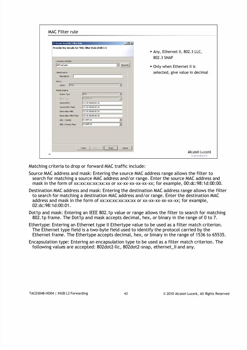
7/18/2019 Alu - A7302 Isam Fttu Operator Gpon Nant-e_ce-PDF
http://slidepdf.com/reader/full/alu-a7302-isam-fttu-operator-gpon-nant-ece-pdf 348/432
© 2010 Alcatel-Lucent, All Rights ReservedTAC03048-HO04 | IHUB L3 Forwarding 43
43
MAC Filter rule
Any, Ethernet II, 802.3 LLC,
802.3 SNAP
Only when Ethernet II is
selected, give value in decimal
Matching criteria to drop or forward MAC traffic include:
Source MAC address and mask: Entering the source MAC address range allows the filter tosearch for matching a source MAC address and/or range. Enter the source MAC address andmask in the form of xx:xx:xx:xx:xx:xx or xx-xx-xx-xx-xx-xx; for example, 00:dc:98:1d:00:00.
Destination MAC address and mask: Entering the destination MAC address range allows the filterto search for matching a destination MAC address and/or range. Enter the destination MACaddress and mask in the form of xx:xx:xx:xx:xx:xx or xx-xx-xx-xx-xx-xx; for example,02:dc:98:1d:00:01.
Dot1p and mask: Entering an IEEE 802.1p value or range allows the filter to search for matching802.1p frame. The Dot1p and mask accepts decimal, hex, or binary in the range of 0 to 7.
Ethertype: Entering an Ethernet type II Ethertype value to be used as a filter match criterion.The Ethernet type field is a two-byte field used to identify the protocol carried by theEthernet frame. The Ethertype accepts decimal, hex, or binary in the range of 1536 to 65535.
Encapsulation type: Entering an encapsulation type to be used as a filter match criterion. Thefollowing values are accepted: 802dot2-llc, 802dot2-snap, ethernet_II and any.
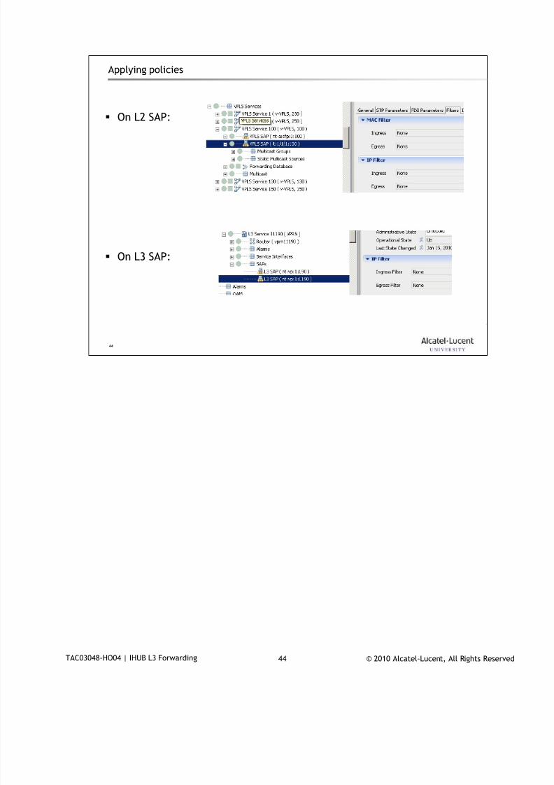
7/18/2019 Alu - A7302 Isam Fttu Operator Gpon Nant-e_ce-PDF
http://slidepdf.com/reader/full/alu-a7302-isam-fttu-operator-gpon-nant-ece-pdf 349/432
© 2010 Alcatel-Lucent, All Rights ReservedTAC03048-HO04 | IHUB L3 Forwarding 44
44
Applying policies
On L2 SAP:
On L3 SAP:

7/18/2019 Alu - A7302 Isam Fttu Operator Gpon Nant-e_ce-PDF
http://slidepdf.com/reader/full/alu-a7302-isam-fttu-operator-gpon-nant-ece-pdf 350/432
© 2010 Alcatel-Lucent, All Rights ReservedTAC03048-HO04 | IHUB L3 Forwarding 45
45
Filter policy configuration – CLI : IP filter
configure filter ip-filter <ID> :
ip-filter 1 create
description "Drop all"
scope exclusiveexit
ip-filter 2 create
default-action forward
description "Forward all"
exit
ip-filter 1000 create
default-action forward
description "test"
entry 30 create
match
dscp cp35
exit
no action
exit
entry 40 create
match protocol icmp
icmp-code 5
exit
action drop
exit
exit

7/18/2019 Alu - A7302 Isam Fttu Operator Gpon Nant-e_ce-PDF
http://slidepdf.com/reader/full/alu-a7302-isam-fttu-operator-gpon-nant-ece-pdf 351/432
© 2010 Alcatel-Lucent, All Rights ReservedTAC03048-HO04 | IHUB L3 Forwarding 46
46
Filter policy configuration – CLI : MAC filter
configure filter mac-filter <ID> :
mac-filter 1 createdescription "Drop all"
exit
mac-filter 2 create
entry 1 create
match
dot1p 2 7
exit
action forward
exit
exit
mac-filter 3 create
default-action forward
description "Forward all"
exit

7/18/2019 Alu - A7302 Isam Fttu Operator Gpon Nant-e_ce-PDF
http://slidepdf.com/reader/full/alu-a7302-isam-fttu-operator-gpon-nant-ece-pdf 352/432
© 2010 Alcatel-Lucent, All Rights ReservedTAC03048-HO04 | IHUB L3 Forwarding 47
47
Base Router configuration6
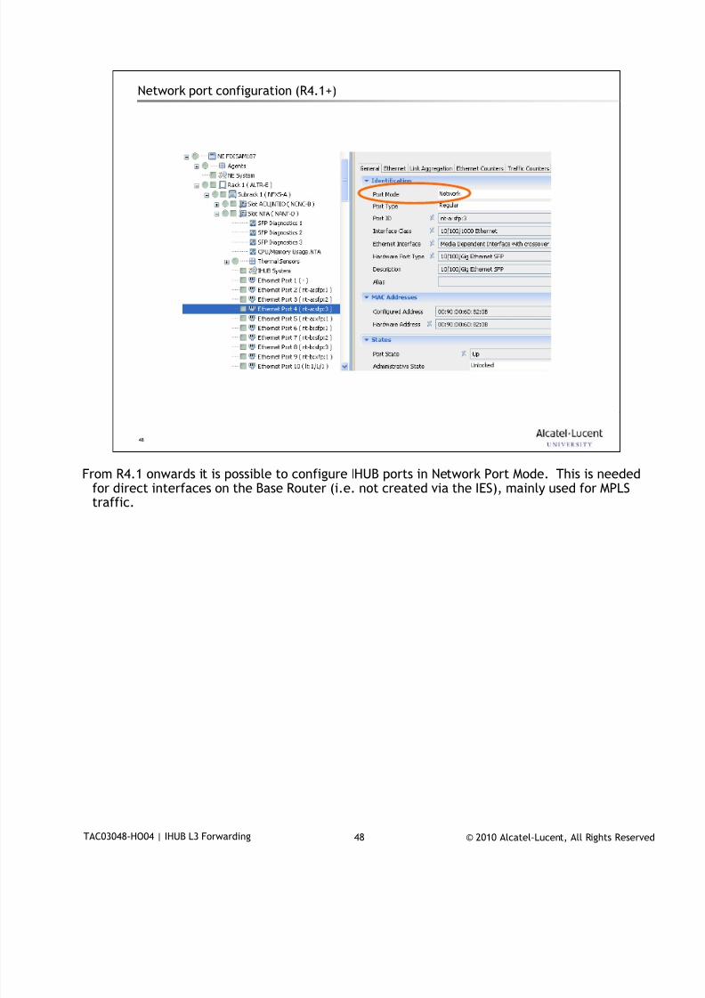
7/18/2019 Alu - A7302 Isam Fttu Operator Gpon Nant-e_ce-PDF
http://slidepdf.com/reader/full/alu-a7302-isam-fttu-operator-gpon-nant-ece-pdf 353/432
© 2010 Alcatel-Lucent, All Rights ReservedTAC03048-HO04 | IHUB L3 Forwarding 48
48
Network port configuration (R4.1+)
From R4.1 onwards it is possible to configure IHUB ports in Network Port Mode. This is needed
for direct interfaces on the Base Router (i.e. not created via the IES), mainly used for MPLStraffic.
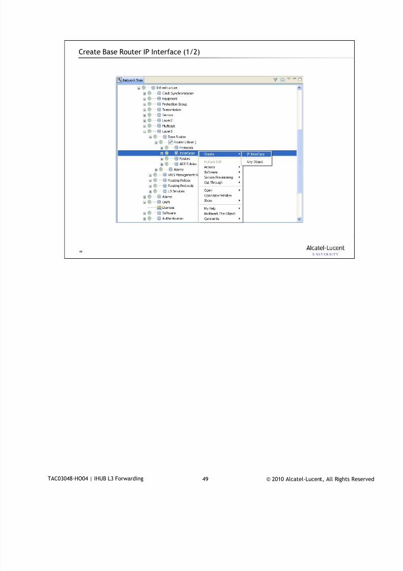
7/18/2019 Alu - A7302 Isam Fttu Operator Gpon Nant-e_ce-PDF
http://slidepdf.com/reader/full/alu-a7302-isam-fttu-operator-gpon-nant-ece-pdf 354/432
© 2010 Alcatel-Lucent, All Rights ReservedTAC03048-HO04 | IHUB L3 Forwarding 49
49
Create Base Router IP Interface (1/2)
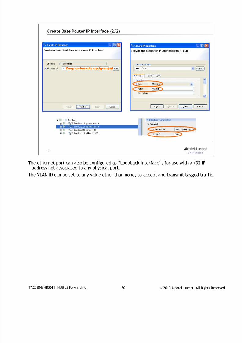
7/18/2019 Alu - A7302 Isam Fttu Operator Gpon Nant-e_ce-PDF
http://slidepdf.com/reader/full/alu-a7302-isam-fttu-operator-gpon-nant-ece-pdf 355/432
© 2010 Alcatel-Lucent, All Rights ReservedTAC03048-HO04 | IHUB L3 Forwarding 50
50
Create Base Router IP Interface (2/2)
Keep automatic assignment
The ethernet port can also be configured as “Loopback Interface”, for use with a /32 IP
address not associated to any physical port.
The VLAN ID can be set to any value other than none, to accept and transmit tagged traffic.
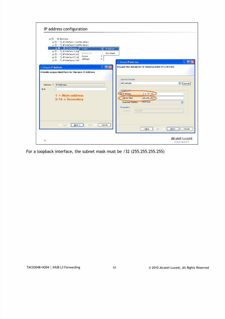
7/18/2019 Alu - A7302 Isam Fttu Operator Gpon Nant-e_ce-PDF
http://slidepdf.com/reader/full/alu-a7302-isam-fttu-operator-gpon-nant-ece-pdf 356/432
© 2010 Alcatel-Lucent, All Rights ReservedTAC03048-HO04 | IHUB L3 Forwarding 51
51
IP address configuration
1 = Main address2-16 = Secondary
For a loopback interface, the subnet mask must be /32 (255.255.255.255)
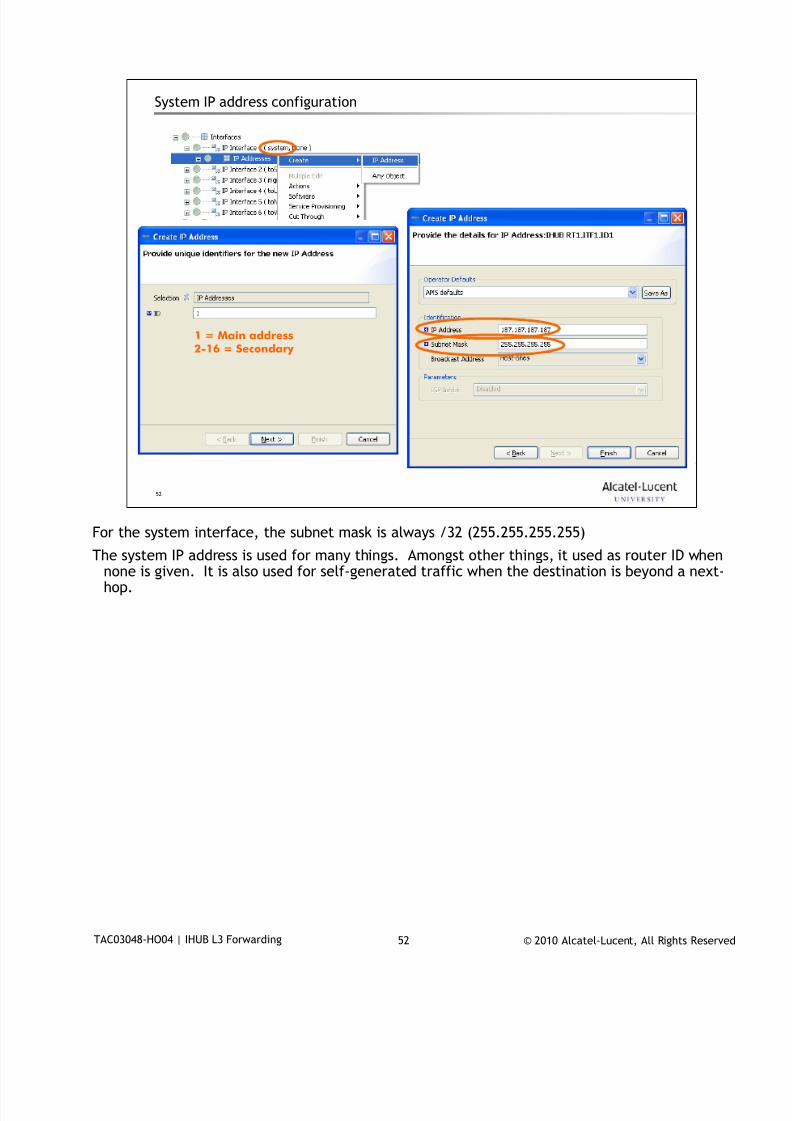
7/18/2019 Alu - A7302 Isam Fttu Operator Gpon Nant-e_ce-PDF
http://slidepdf.com/reader/full/alu-a7302-isam-fttu-operator-gpon-nant-ece-pdf 357/432
© 2010 Alcatel-Lucent, All Rights ReservedTAC03048-HO04 | IHUB L3 Forwarding 52
52
System IP address configuration
1 = Main address2-16 = Secondary
For the system interface, the subnet mask is always /32 (255.255.255.255)
The system IP address is used for many things. Amongst other things, it used as router ID whennone is given. It is also used for self-generated traffic when the destination is beyond a next-hop.

7/18/2019 Alu - A7302 Isam Fttu Operator Gpon Nant-e_ce-PDF
http://slidepdf.com/reader/full/alu-a7302-isam-fttu-operator-gpon-nant-ece-pdf 358/432
© 2010 Alcatel-Lucent, All Rights ReservedTAC03048-HO04 | IHUB L3 Forwarding 53
53
CLI
configure
port nt-a:sfp:3
ethernet mode network
exit
no shutdown
exit
configure
router
interface "system"
address 187.187.187.187/32
exitinterface "toSIM4"
address 10.4.187.187/24
port nt-a:sfp:3:0
exit
exit

7/18/2019 Alu - A7302 Isam Fttu Operator Gpon Nant-e_ce-PDF
http://slidepdf.com/reader/full/alu-a7302-isam-fttu-operator-gpon-nant-ece-pdf 359/432
© 2010 Alcatel-Lucent, All Rights ReservedTAC03048-HO04 | IHUB L3 Forwarding 54
54
www.alcatel-lucent.comwww.alcatel-lucent.com
7/18/2019 Alu - A7302 Isam Fttu Operator Gpon Nant-e_ce-PDF
http://slidepdf.com/reader/full/alu-a7302-isam-fttu-operator-gpon-nant-ece-pdf 360/432
© 2010 Alcatel-Lucent, All Rights ReservedDocument Number | Document Title 1
QoS in 7302 ISAM/GPON
… for the NGLT-A
During class please switch off your mobile, pager or other that may interrupt.

7/18/2019 Alu - A7302 Isam Fttu Operator Gpon Nant-e_ce-PDF
http://slidepdf.com/reader/full/alu-a7302-isam-fttu-operator-gpon-nant-ece-pdf 361/432
© 2010 Alcatel-Lucent, All Rights ReservedDocument Number | Document Title 2
Objective
Upon completion of the module you will be able to
describe the use of T-CONTs and the T-CONT types
configure and explain the parameters in the BW profile
explain QoS functions in the ONT, uptream and downstream
configure and explain the ingress-qos-profile
explain QoS functions in the LT, upstream and downstream
configure and explain hierarchical scheduling + rate limiting
7/18/2019 Alu - A7302 Isam Fttu Operator Gpon Nant-e_ce-PDF
http://slidepdf.com/reader/full/alu-a7302-isam-fttu-operator-gpon-nant-ece-pdf 362/432
© 2010 Alcatel-Lucent, All Rights ReservedDocument Number | Document Title 3
3
Table of Contents
1.The 7302 management model
2.The LT comparison
3.Overall QoS flow
4.Upstream bandwidth management on the PON
5.Upstream QoS architecture
6.Downstream QoS architecture
7.Exercises
Agenda Pages
This page allows for the listing of the sections within a presentation.

7/18/2019 Alu - A7302 Isam Fttu Operator Gpon Nant-e_ce-PDF
http://slidepdf.com/reader/full/alu-a7302-isam-fttu-operator-gpon-nant-ece-pdf 363/432
© 2010 Alcatel-Lucent, All Rights ReservedDocument Number | Document Title 4
4
The 7302 management model1
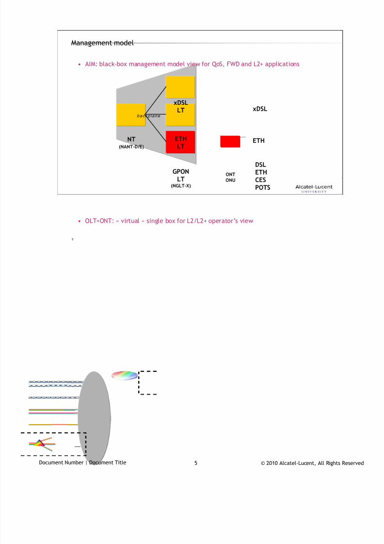
7/18/2019 Alu - A7302 Isam Fttu Operator Gpon Nant-e_ce-PDF
http://slidepdf.com/reader/full/alu-a7302-isam-fttu-operator-gpon-nant-ece-pdf 364/432
© 2010 Alcatel-Lucent, All Rights ReservedDocument Number | Document Title 5
5
• AIM: black-box management model view for QoS, FWD and L2+ applications
• OLT+ONT: « virtual » single box for L2/L2+ operator’s view
Management model
NT(NANT-D/E)
xDSLLT
GPON
LT(NGLT-X)
ETHLT
ONTONU
backplane
xDSL
ETH
DSLETHCESPOTS
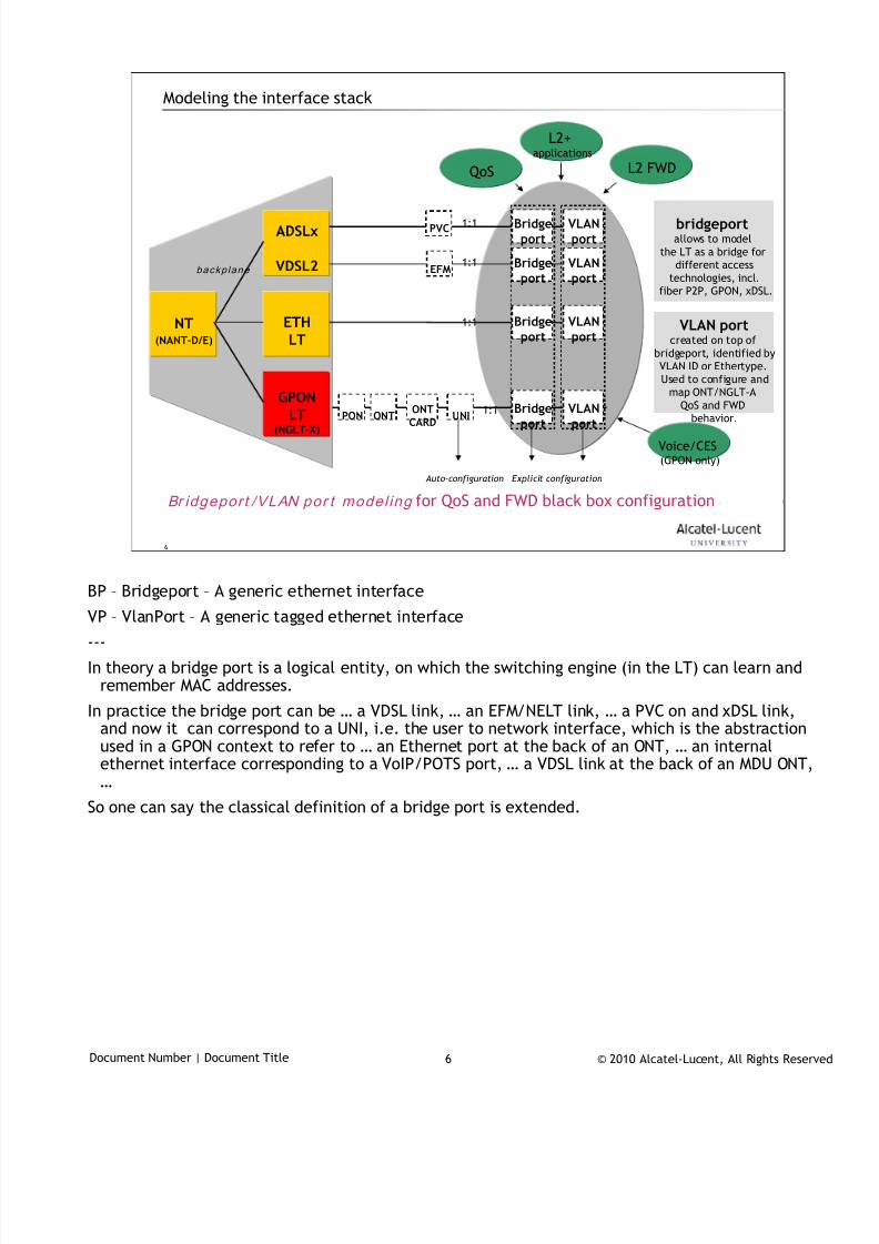
7/18/2019 Alu - A7302 Isam Fttu Operator Gpon Nant-e_ce-PDF
http://slidepdf.com/reader/full/alu-a7302-isam-fttu-operator-gpon-nant-ece-pdf 365/432
© 2010 Alcatel-Lucent, All Rights ReservedDocument Number | Document Title 6
6
Modeling the interface stack
NT(NANT-D/E)
ADSLx
VDSL2
GPONLT(NGLT-X)
ETHLT
backplane
PON ONT UNI
EFM
PVC
Bridgeport
Bridgeport
Bridgeport
Bridgeport
VLANport
VLANport
VLANport
VLANport
Br idgeport /VLAN por t model ing for QoS and FWD black box configuration
1:1
1:1
1:1
1:1
QoS
L2+applications
L2 FWD
Voice/CES(GPON only)
bridgeportallows to model
the LT as a bridge fordifferent access
technologies, incl.fiber P2P, GPON, xDSL.
VLAN portcreated on top of
bridgeport, identified byVLAN ID or Ethertype.
Used to configure andmap ONT/NGLT-A
QoS and FWDbehavior.
Explicit configuration Auto-configuration
ONTCARD
BP – Bridgeport – A generic ethernet interface
VP – VlanPort – A generic tagged ethernet interface
---
In theory a bridge port is a logical entity, on which the switching engine (in the LT) can learn andremember MAC addresses.
In practice the bridge port can be … a VDSL link, … an EFM/NELT link, … a PVC on and xDSL link,and now it can correspond to a UNI, i.e. the user to network interface, which is the abstractionused in a GPON context to refer to … an Ethernet port at the back of an ONT, … an internalethernet interface corresponding to a VoIP/POTS port, … a VDSL link at the back of an MDU ONT,…
So one can say the classical definition of a bridge port is extended.

7/18/2019 Alu - A7302 Isam Fttu Operator Gpon Nant-e_ce-PDF
http://slidepdf.com/reader/full/alu-a7302-isam-fttu-operator-gpon-nant-ece-pdf 366/432
© 2010 Alcatel-Lucent, All Rights ReservedDocument Number | Document Title 7
7
The LT comparison2
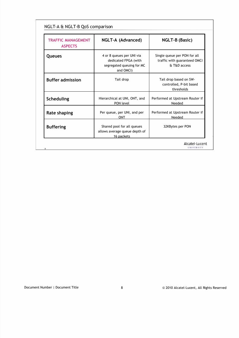
7/18/2019 Alu - A7302 Isam Fttu Operator Gpon Nant-e_ce-PDF
http://slidepdf.com/reader/full/alu-a7302-isam-fttu-operator-gpon-nant-ece-pdf 367/432
© 2010 Alcatel-Lucent, All Rights ReservedDocument Number | Document Title 8
8
NGLT-A & NGLT-B QoS comparison
Tail drop based on SW-
controlled, P-bit based
thresholds
Tail dropBuffer admission
Single queue per PON for all
traffic with guaranteed OMCI
& T&D access
4 or 8 queues per UNI via
dedicated FPGA (with
segregated queuing for MC
and OMCI)
Queues
32KBytes per PONShared pool for all queues
allows average queue depth of
16 packets
Buffering
Performed at Upstream Router if
Needed
Per queue, per UNI, and per
ONT
Rate shaping
Performed at Upstream Router if
Needed
Hierarchical at UNI, ONT, and
PON levelScheduling
NGLT-B (Basic)NGLT-A (Advanced)TRAFFIC MANAGEMENT
ASPECTS
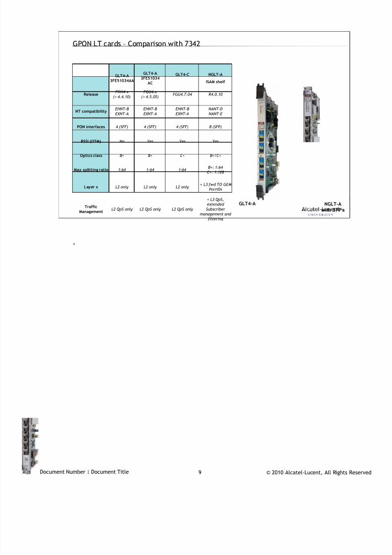
7/18/2019 Alu - A7302 Isam Fttu Operator Gpon Nant-e_ce-PDF
http://slidepdf.com/reader/full/alu-a7302-isam-fttu-operator-gpon-nant-ece-pdf 368/432
© 2010 Alcatel-Lucent, All Rights ReservedDocument Number | Document Title 9
9
GPON LT cards – Comparison with 7342
L2 QoS only
L2 only
1:64
C+
Yes
4 (SFF)
EHNT-B
EXNT-A
FGU4.7.04
GLT4-C
YesYesNoRSSI (OTM)
B+/C+B+B+Optics class
8 (SFP)4 (SFF)4 (SFF)PON interfaces
TrafficManagement
Layer x
Max splitting ratio
NT compatibility
Release
+ L3 fwd TO GEM
PortIDsL2 only L2 only
+ L3 QoS,
extended
Subscriber
management and
filtering
L2 QoS only L2 QoS only
B+: 1:64
C+: 1:1281:641:64
NANT-D
NANT-E
EHNT-B
EXNT-A
EHNT-B
EXNT-A
R4.0.10 FGU4.x
(> 4.5.05)
FGU4.x
(> 4.4.10)
NGLT-A
ISAM shelf
GLT4-A3FE51034
AC
GLT4-A3FE51034AA
NGLT-A
with SFPs
GLT4-A

7/18/2019 Alu - A7302 Isam Fttu Operator Gpon Nant-e_ce-PDF
http://slidepdf.com/reader/full/alu-a7302-isam-fttu-operator-gpon-nant-ece-pdf 369/432
© 2010 Alcatel-Lucent, All Rights ReservedDocument Number | Document Title 10
10
Overall QoS flow3
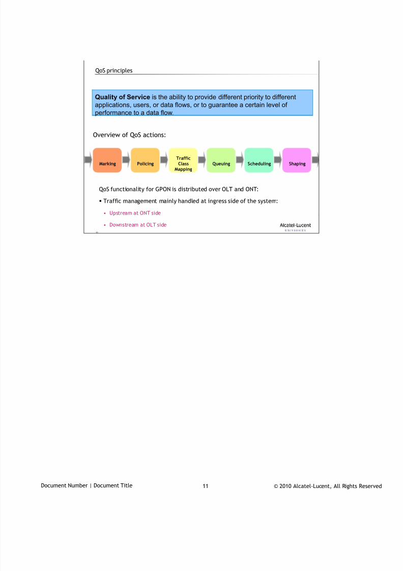
7/18/2019 Alu - A7302 Isam Fttu Operator Gpon Nant-e_ce-PDF
http://slidepdf.com/reader/full/alu-a7302-isam-fttu-operator-gpon-nant-ece-pdf 370/432
© 2010 Alcatel-Lucent, All Rights ReservedDocument Number | Document Title 11
11
QoS principles
Marking PolicingTrafficClass
MappingQueuing Scheduling Shaping
Quality of Service is the ability to provide different priority to different
applications, users, or data flows, or to guarantee a certain level of
performance to a data flow.
Overview of QoS actions:
QoS functionality for GPON is distributed over OLT and ONT:
Traffic management mainly handled at ingress side of the system:
• Upstream at ONT side
• Downstream at OLT side
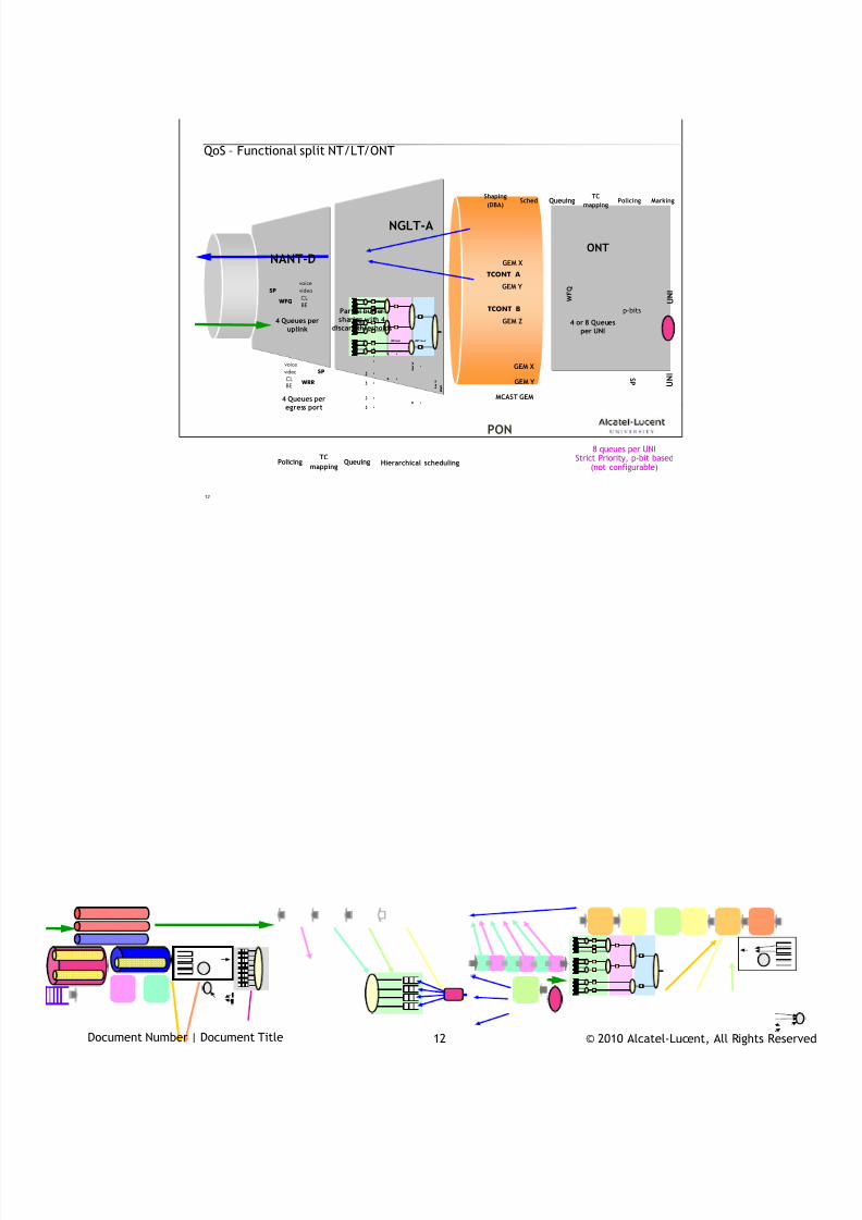
7/18/2019 Alu - A7302 Isam Fttu Operator Gpon Nant-e_ce-PDF
http://slidepdf.com/reader/full/alu-a7302-isam-fttu-operator-gpon-nant-ece-pdf 371/432
© 2010 Alcatel-Lucent, All Rights ReservedDocument Number | Document Title 12
12
ONT
QoS – Functional split NT/LT/ONT
NANT-D
NGLT-A
PON
U N I
WF Q
WF Q
WF Q
WF Q
WF Q
S P
S P
S P , WF Q
S P
S P , WF Q
S
S
S
S
G P O N
Queue level UNI l evel ONT level
S
S
S
S
S
S
S
WF Q
WF Q
WF Q
WF Q
WF Q
S P
S P
S P , WF Q
S P
S P , WF Q
S
S
S
S
G P O N
Queue level UNI l evel ONT level
S
S
S
S
S
S
S
4 Queues peregress port
WRR
voice
video
CLBE
SP
U N I
GEM Y
GEM X
MCAST GEM
TCONT A
TCONT B
GEM Y
GEM X
GEM Z
p-bits
WFQ
voice
video
CL
BE
SP
Partial buffersharing with 4
discard thresholds4 Queues per
uplink
8 queues per UNIStrict Priority, p-bit based
(not configurable)Policing
TC
mappingQueuing
MarkingPolicingTCmapping
QueuingSchedShaping(DBA)
W F Q
Hierarchical scheduling
S P
4 or 8 Queuesper UNI

7/18/2019 Alu - A7302 Isam Fttu Operator Gpon Nant-e_ce-PDF
http://slidepdf.com/reader/full/alu-a7302-isam-fttu-operator-gpon-nant-ece-pdf 372/432
© 2010 Alcatel-Lucent, All Rights ReservedDocument Number | Document Title 13
13
Upstream bandwidth management
… on the PON4
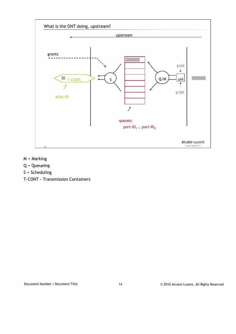
7/18/2019 Alu - A7302 Isam Fttu Operator Gpon Nant-e_ce-PDF
http://slidepdf.com/reader/full/alu-a7302-isam-fttu-operator-gpon-nant-ece-pdf 373/432
© 2010 Alcatel-Lucent, All Rights ReservedDocument Number | Document Title 14
14
What is the ONT doing, upstream?
upstream
T-CONT1uni
pvid
p-bit
grants
alloc-ID
port-ID1 … port-ID8
Q/MS
queues:
M = Marking
Q = Queueing
S = Scheduling
T-CONT - Transmission Containers
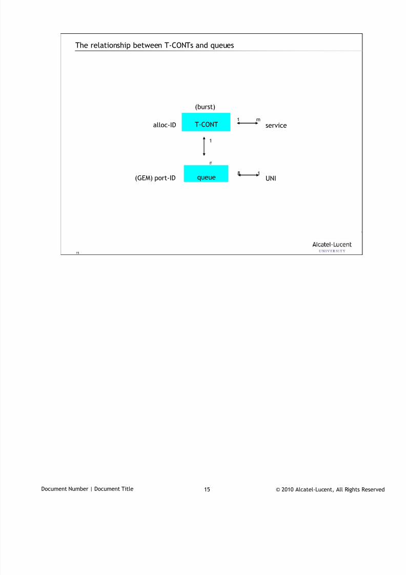
7/18/2019 Alu - A7302 Isam Fttu Operator Gpon Nant-e_ce-PDF
http://slidepdf.com/reader/full/alu-a7302-isam-fttu-operator-gpon-nant-ece-pdf 374/432
© 2010 Alcatel-Lucent, All Rights ReservedDocument Number | Document Title 15
15
The relationship between T-CONTs and queues
T-CONT
queue
alloc-ID
(GEM) port-ID
1
n
service1 m
(burst)
UNI8 1
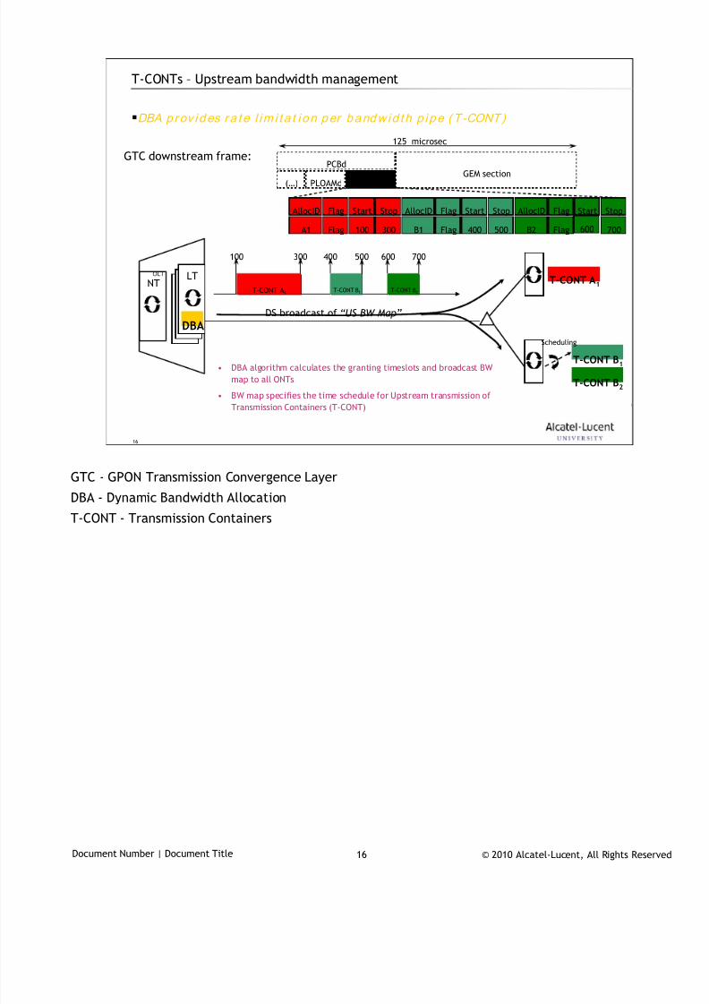
7/18/2019 Alu - A7302 Isam Fttu Operator Gpon Nant-e_ce-PDF
http://slidepdf.com/reader/full/alu-a7302-isam-fttu-operator-gpon-nant-ece-pdf 375/432
© 2010 Alcatel-Lucent, All Rights ReservedDocument Number | Document Title 16
16
T-CONTs – Upstream bandwidth management
125 microsec
OLT
NTLT T-CONT A1
DBA
DS broadcast of “US BW Map”
PCBd
PLOAMd US BW Map(…)GEM section
AllocID Flag Start Stop
A1 Flag 100 300
AllocID Flag Start Stop
B1 Flag 400 500
AllocID Flag Start Stop
B2 Flag 600 700
GTC downstream frame:
100 300 400 500 600 700
T-CONT B2T-CONT B1T-CONT A1
T-CONT B1
T-CONT B2
Scheduling
• DBA algorithm calculates the granting timeslots and broadcast BW
map to all ONTs
• BW map specifies the time schedule for Upstream transmission of
Transmission Containers (T-CONT)
DBA p rov ides ra te l im i t a t i on per bandw id th p ipe (T -CONT)
GTC - GPON Transmission Convergence Layer
DBA - Dynamic Bandwidth Allocation
T-CONT - Transmission Containers
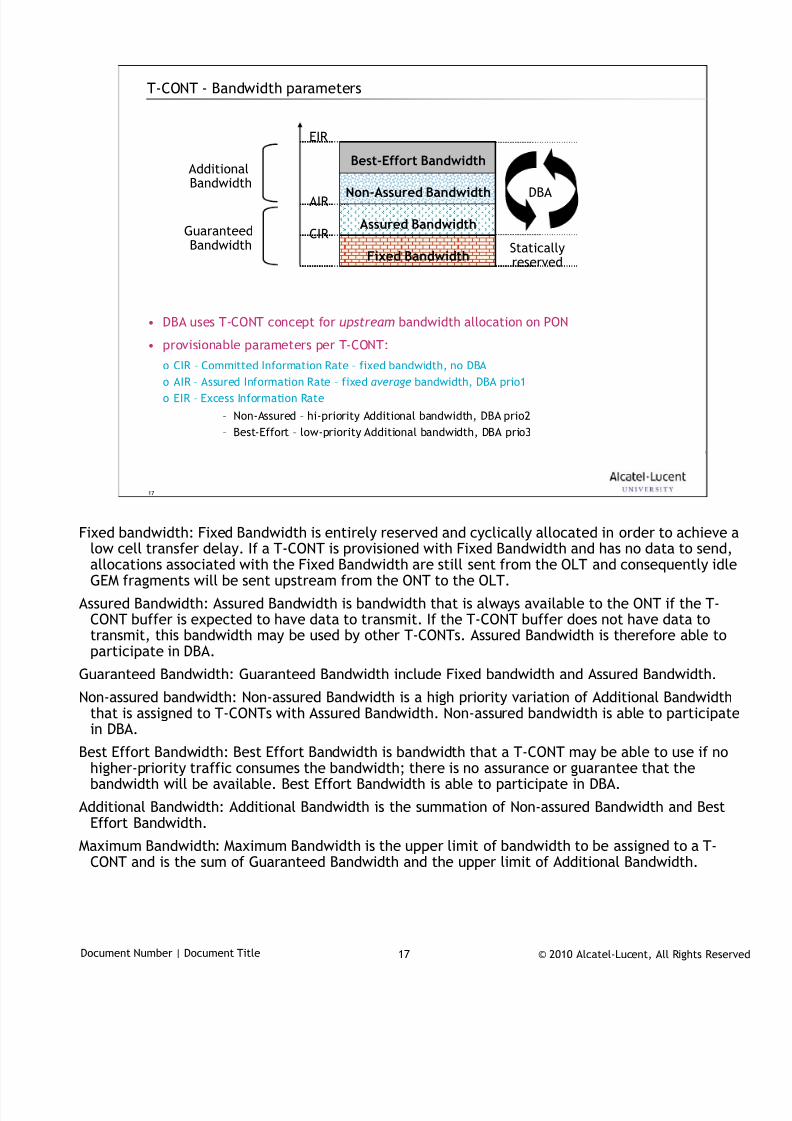
7/18/2019 Alu - A7302 Isam Fttu Operator Gpon Nant-e_ce-PDF
http://slidepdf.com/reader/full/alu-a7302-isam-fttu-operator-gpon-nant-ece-pdf 376/432
© 2010 Alcatel-Lucent, All Rights ReservedDocument Number | Document Title 17
17
T-CONT - Bandwidth parameters
• DBA uses T-CONT concept for upstream bandwidth allocation on PON
• provisionable parameters per T-CONT:
o CIR – Committed Information Rate – fixed bandwidth, no DBAo AIR – Assured Information Rate – fixed average bandwidth, DBA prio1
o EIR – Excess Information Rate
– Non-Assured – hi-priority Additional bandwidth, DBA prio2
– Best-Effort – low-priority Additional bandwidth, DBA prio3
Fixed Bandwidth
Assured Bandwidth
Non-Assured Bandwidth
Best-Effort BandwidthAdditional
Bandwidth
GuaranteedBandwidth
EIR
AIR
CIR
DBA
Staticallyreserved
Fixed bandwidth: Fixed Bandwidth is entirely reserved and cyclically allocated in order to achieve a
low cell transfer delay. If a T-CONT is provisioned with Fixed Bandwidth and has no data to send,allocations associated with the Fixed Bandwidth are still sent from the OLT and consequently idleGEM fragments will be sent upstream from the ONT to the OLT.
Assured Bandwidth: Assured Bandwidth is bandwidth that is always available to the ONT if the T-CONT buffer is expected to have data to transmit. If the T-CONT buffer does not have data totransmit, this bandwidth may be used by other T-CONTs. Assured Bandwidth is therefore able toparticipate in DBA.
Guaranteed Bandwidth: Guaranteed Bandwidth include Fixed bandwidth and Assured Bandwidth.
Non-assured bandwidth: Non-assured Bandwidth is a high priority variation of Additional Bandwidththat is assigned to T-CONTs with Assured Bandwidth. Non-assured bandwidth is able to participate
in DBA.Best Effort Bandwidth: Best Effort Bandwidth is bandwidth that a T-CONT may be able to use if no
higher-priority traffic consumes the bandwidth; there is no assurance or guarantee that thebandwidth will be available. Best Effort Bandwidth is able to participate in DBA.
Additional Bandwidth: Additional Bandwidth is the summation of Non-assured Bandwidth and BestEffort Bandwidth.
Maximum Bandwidth: Maximum Bandwidth is the upper limit of bandwidth to be assigned to a T-CONT and is the sum of Guaranteed Bandwidth and the upper limit of Additional Bandwidth.
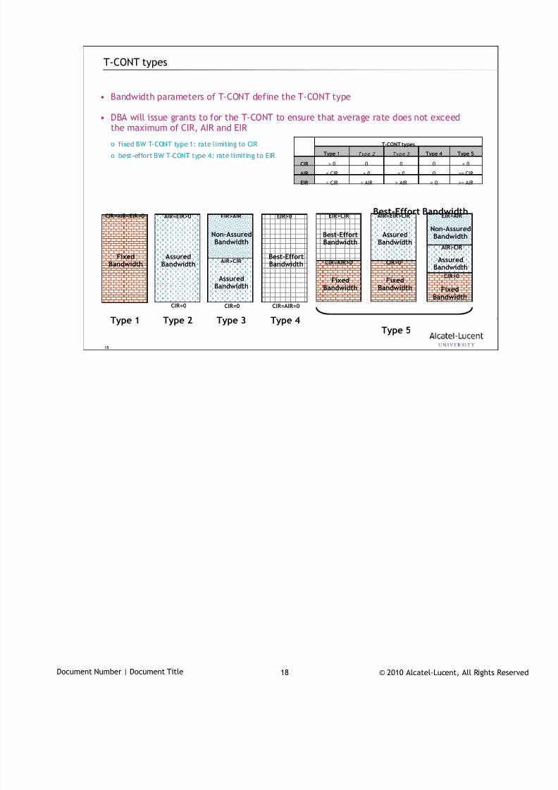
7/18/2019 Alu - A7302 Isam Fttu Operator Gpon Nant-e_ce-PDF
http://slidepdf.com/reader/full/alu-a7302-isam-fttu-operator-gpon-nant-ece-pdf 377/432
© 2010 Alcatel-Lucent, All Rights ReservedDocument Number | Document Title 18
18
T-CONT types
• Bandwidth parameters of T-CONT define the T-CONT type
• DBA will issue grants to for the T-CONT to ensure that average rate does not exceed
the maximum of CIR, AIR and EIR
o fixed BW T-CONT type 1: rate limiting to CIR
o best-effort BW T-CONT type 4: rate limiting to EIR
FixedBandwidth
Best-Effort Bandwidth
AssuredBandwidth
AssuredBandwidth
Non-AssuredBandwidth
Best-EffortBandwidth
Non-AssuredBandwidth
AssuredBandwidth
FixedBandwidth
CIR=AIR=EIR>0 AIR=EIR>0
CIR=0
EIR>AIR
AIR>CIR
CIR=0 CIR=AIR=0
EIR>0 EIR>AIR
AIR>CIR
CIR>0
Type 1 Type 2 Type 3 Type 4
Best-EffortBandwidth
FixedBandwidth
EIR>CIR
CIR=AIR>0
Type 5
FixedBandwidth
AIR=EIR>CIR
CIR>0
AssuredBandwidth
>= AIR> 0> AIR= AIR= CIREIR
>= CIR0> 0> 0= CIRAIR
> 0000> 0CIR
Type 5Type 4Type 3 Type 2 Type 1
T-CONT types
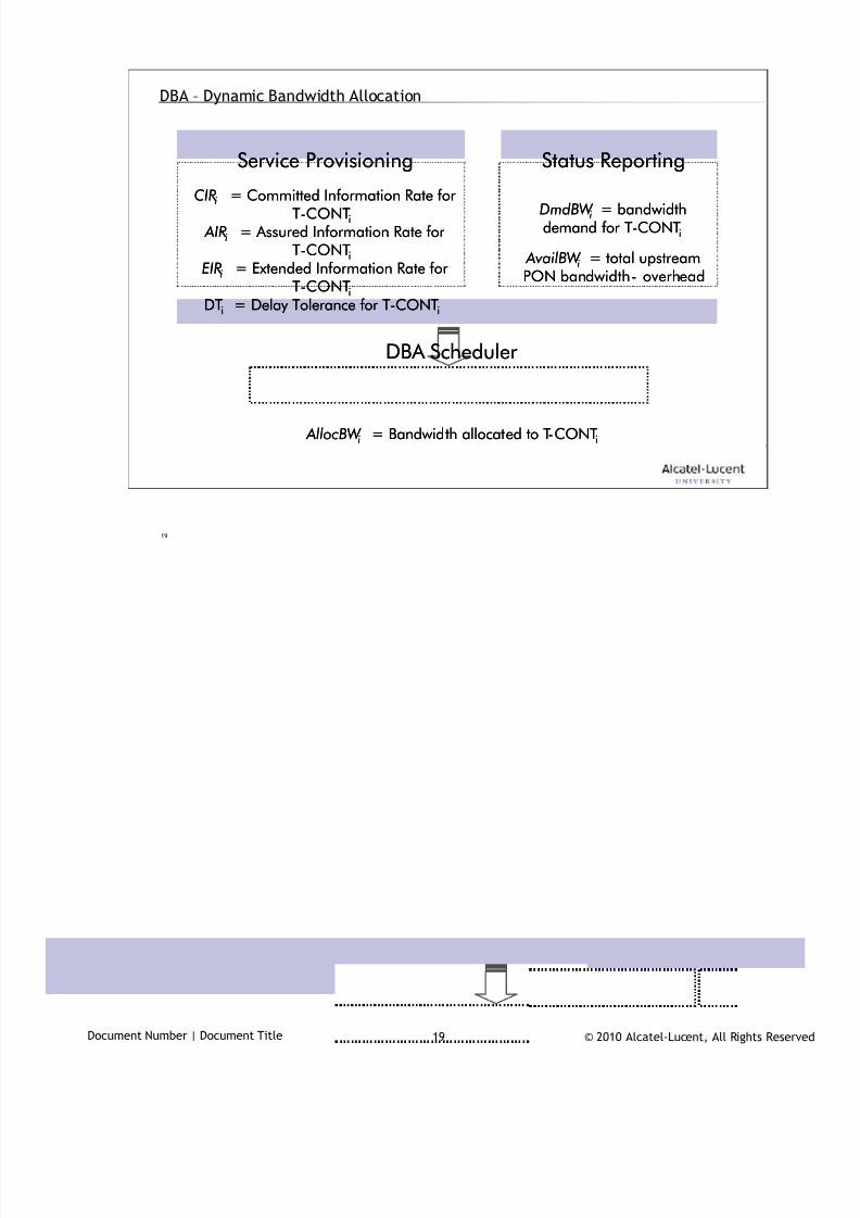
7/18/2019 Alu - A7302 Isam Fttu Operator Gpon Nant-e_ce-PDF
http://slidepdf.com/reader/full/alu-a7302-isam-fttu-operator-gpon-nant-ece-pdf 378/432
© 2010 Alcatel-Lucent, All Rights ReservedDocument Number | Document Title 19
19
DBA – Dynamic Bandwidth Allocation
DmdBW i = bandwidthdemand for T-CONTi
AvailBW i = total upstreamPON bandwidth - overhead
CIRi = Committed Information Rate forT-CONTi
AIRi
= Assured Information Rate forT-CONTi
EIRi = Extended Information Rate forT-CONTi
DTi = Delay Tolerance for T-CONTi
Service Provisioning Status Reporting
DBA Scheduler
AllocBW i = Bandwidth allocated to T-CONTi
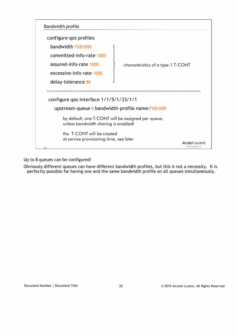
7/18/2019 Alu - A7302 Isam Fttu Operator Gpon Nant-e_ce-PDF
http://slidepdf.com/reader/full/alu-a7302-isam-fttu-operator-gpon-nant-ece-pdf 379/432
© 2010 Alcatel-Lucent, All Rights ReservedDocument Number | Document Title 20
20
configure qos profiles
bandwidth FXB1000
committed-info-rate 1000
assured-info-rate 1000
excessive-info rate 1000
delay-tolerance 80
configure qos interface 1/1/5/1/33/1/1
upstream-queue 0 bandwidth-profile name:FXB1000
Bandwidth profile
by default, one T-CONT will be assigned per queue,unless bandwidth sharing is enabled!
characteristics of a type-1 T-CONT
the T-CONT will be createdat service provisioning time, see later
Up to 8 queues can be configured!
Obviously different queues can have different bandwidth profiles, but this is not a necessity. It isperfectly possible for having one and the same bandwidth profile on all queues simultaneously.
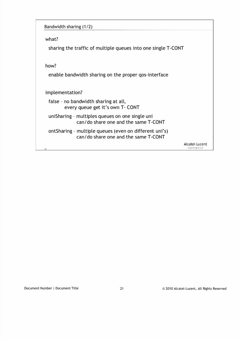
7/18/2019 Alu - A7302 Isam Fttu Operator Gpon Nant-e_ce-PDF
http://slidepdf.com/reader/full/alu-a7302-isam-fttu-operator-gpon-nant-ece-pdf 380/432
© 2010 Alcatel-Lucent, All Rights ReservedDocument Number | Document Title 21
21
Bandwidth sharing (1/2)
what?
sharing the traffic of multiple queues into one single T-CONT
how?
enable bandwidth sharing on the proper qos-interface
implementation?
false – no bandwidth sharing at all,
every queue get it’s own T- CONT
uniSharing – multiples queues on one single uni
can/do share one and the same T-CONT
ontSharing – multiple queues (even on different uni’s)
can/do share one and the same T-CONT

7/18/2019 Alu - A7302 Isam Fttu Operator Gpon Nant-e_ce-PDF
http://slidepdf.com/reader/full/alu-a7302-isam-fttu-operator-gpon-nant-ece-pdf 381/432
© 2010 Alcatel-Lucent, All Rights ReservedDocument Number | Document Title 22
22
Bandwidth sharing (2/2)
example?
configure qos interface 1/1/5/1/33/1/1
upstream-queue 0
bandwidth-profile name:CBR1000
bandwidth-sharing uni-sharing
upstream-queue 1
bandwidth-profile name:CBR1000
bandwidth-sharing uni-sharing
one single T-CONT will be created (at service prov. time)which collects the data from queue 0 and 1as they have the same bandwidth profile
this way, multiple services (on the same UNI) share the same T-CONTso there might be a need to do service policing on the LT
The bandwidth-sharing parameter can be set to uni-sharing or ont-sharing.
The bandwidth-sharing concept is on AMS referred to as shaper sharing.
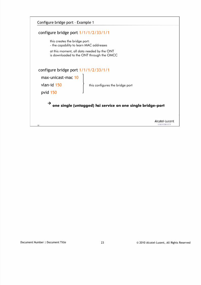
7/18/2019 Alu - A7302 Isam Fttu Operator Gpon Nant-e_ce-PDF
http://slidepdf.com/reader/full/alu-a7302-isam-fttu-operator-gpon-nant-ece-pdf 382/432
© 2010 Alcatel-Lucent, All Rights ReservedDocument Number | Document Title 23
23
Configure bridge port – Example 1
configure bridge port 1/1/1/2/33/1/1
configure bridge port 1/1/1/2/33/1/1
max-unicast-mac 10
vlan-id 150
pvid 150
this creates the bridge port:
- the capability to learn MAC addressesat this moment, all data needed by the ONTis downloaded to the ONT through the OMCC
this configures the bridge port
one single (untagged) hsi service on one single bridge-port
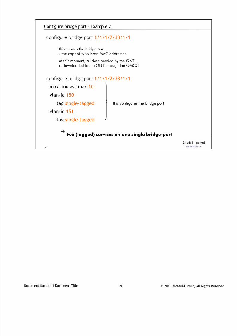
7/18/2019 Alu - A7302 Isam Fttu Operator Gpon Nant-e_ce-PDF
http://slidepdf.com/reader/full/alu-a7302-isam-fttu-operator-gpon-nant-ece-pdf 383/432
© 2010 Alcatel-Lucent, All Rights ReservedDocument Number | Document Title 24
24
Configure bridge port – Example 2
configure bridge port 1/1/1/2/33/1/1
configure bridge port 1/1/1/2/33/1/1
max-unicast-mac 10
vlan-id 150
tag single-tagged
vlan-id 151
tag single-tagged
this creates the bridge port:
- the capability to learn MAC addressesat this moment, all data needed by the ONTis downloaded to the ONT through the OMCC
this configures the bridge port
two (tagged) services on one single bridge-port
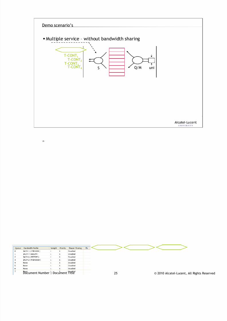
7/18/2019 Alu - A7302 Isam Fttu Operator Gpon Nant-e_ce-PDF
http://slidepdf.com/reader/full/alu-a7302-isam-fttu-operator-gpon-nant-ece-pdf 384/432
© 2010 Alcatel-Lucent, All Rights ReservedDocument Number | Document Title 25
25
Demo scenario’s
Multiple service – without bandwidth sharing
uniQ/MS
T-CONT1
T-CONT2T-CONT3
T-CONT4
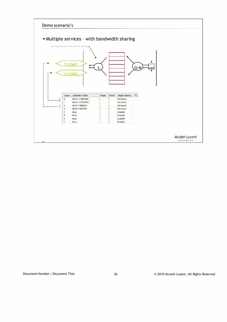
7/18/2019 Alu - A7302 Isam Fttu Operator Gpon Nant-e_ce-PDF
http://slidepdf.com/reader/full/alu-a7302-isam-fttu-operator-gpon-nant-ece-pdf 385/432
© 2010 Alcatel-Lucent, All Rights ReservedDocument Number | Document Title 26
26
Demo scenario’s
Multiple services – with bandwidth sharing
uniQ/MST-CONT1
T-CONT2

7/18/2019 Alu - A7302 Isam Fttu Operator Gpon Nant-e_ce-PDF
http://slidepdf.com/reader/full/alu-a7302-isam-fttu-operator-gpon-nant-ece-pdf 386/432
© 2010 Alcatel-Lucent, All Rights ReservedDocument Number | Document Title 27
27
QoS architecture
… ONT+LT upstream5
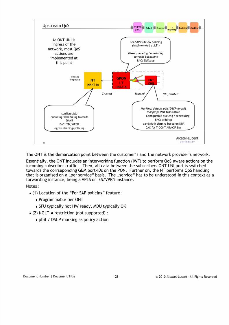
7/18/2019 Alu - A7302 Isam Fttu Operator Gpon Nant-e_ce-PDF
http://slidepdf.com/reader/full/alu-a7302-isam-fttu-operator-gpon-nant-ece-pdf 387/432
© 2010 Alcatel-Lucent, All Rights ReservedDocument Number | Document Title 28
28
Upstream QoS
NT(NANT-D)
GPONLT
(NGLT-A)
ONTONU
Trusted
interface
Trusted (Un)Trusted Trusted
Per-SAP/subflow policing
(implemented at LT!)
Fixed queueing /schedulingtowards Backplane
BAC: Taildrop
Marking: default pbit/DSCP-to-pbit
mapping/ Pbit translation
Configurable queuing / scheduling
BAC: taildrop
bandwidth shaping based on DBA
CAC for T-CONT AIR/CIR BW
configurablequeueing/scheduling towards
EMAN
BAC: TD, WRED
egress shaping/policing
As ONT UNI isingress of the
network, most QoS
actions areimplemented at
this point
MarkingPolicingTC
mappingQueuingSched
Shaping
(DBA)
The ONT is the demarcation point between the customer‘s and the network provider‘s network.
Essentially, the ONT includes an interworking function (IWF) to perform QoS aware actions on theincoming subscriber traffic. Then, all data between the subscribers ONT UNI port is switchedtowards the corrseponding GEM port-IDs on the PON. Further on, the NT performs QoS handlingthat is organised on a „per service“ basis. The „service“ has to be understood in this context as aforwarding instance, being a VPLS or IES/VPRN instance.
Notes :
(1) Location of the “Per SAP policing” feature :
Programmable per ONT
SFU typically not HW ready, MDU typically OK
(2) NGLT-A restriction (not supported) :
pbit / DSCP marking as policy action
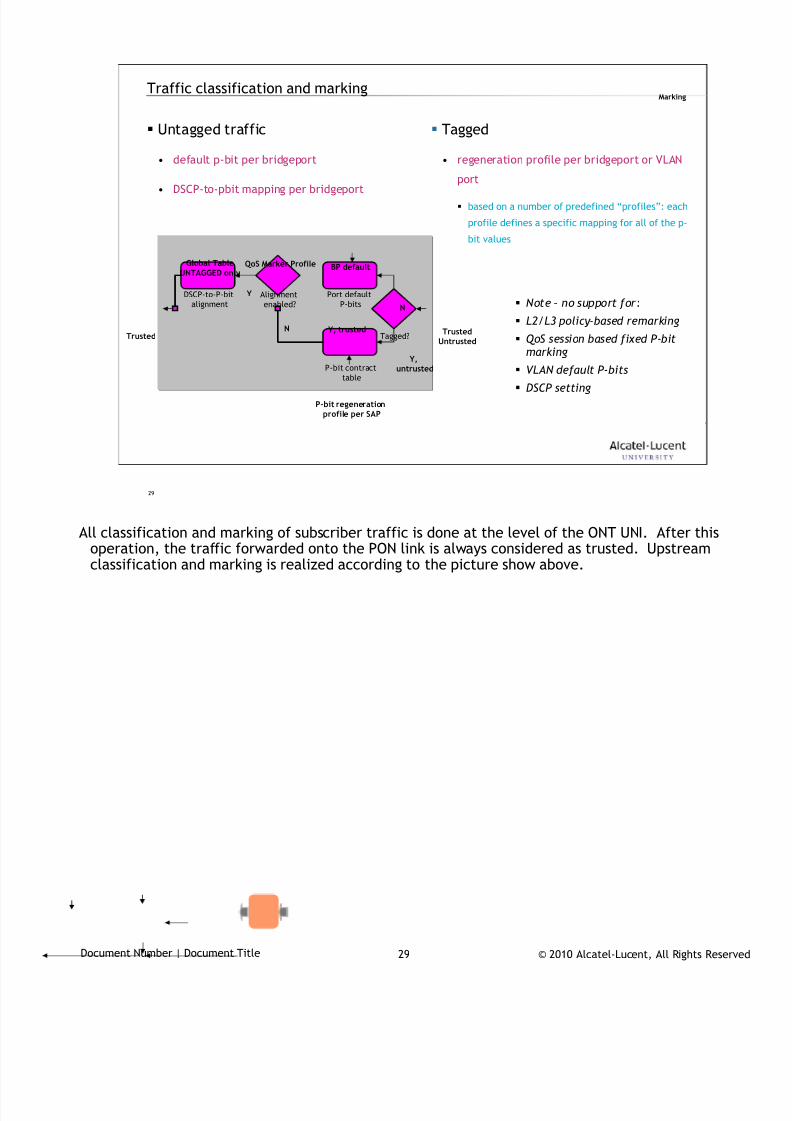
7/18/2019 Alu - A7302 Isam Fttu Operator Gpon Nant-e_ce-PDF
http://slidepdf.com/reader/full/alu-a7302-isam-fttu-operator-gpon-nant-ece-pdf 388/432
© 2010 Alcatel-Lucent, All Rights ReservedDocument Number | Document Title 29
29
Traffic classification and marking
Untagged traffic
• default p-bit per bridgeport
• DSCP-to-pbit mapping per bridgeport
Note – no support for:
L2/L3 policy-based remarking
QoS session based fixed P-bitmarking
VLAN default P-bits
DSCP setting
Port default
P-bits
P-bit contract
table
Tagged?
Alignment
enabled?
DSCP-to-P-bit
alignment
BP default
P-bit regenerationprofile per SAP
Y, trusted
N
Y,untrusted
QoS Marker ProfileGlobal TableUNTAGGED only
TrustedUntrusted
Trusted
Tagged
• regeneration profile per bridgeport or VLAN
port
based on a number of predefined “profiles”: each
profile defines a specific mapping for all of the p-
bit values
Y
N
Marking
All classification and marking of subscriber traffic is done at the level of the ONT UNI. After this
operation, the traffic forwarded onto the PON link is always considered as trusted. Upstreamclassification and marking is realized according to the picture show above.
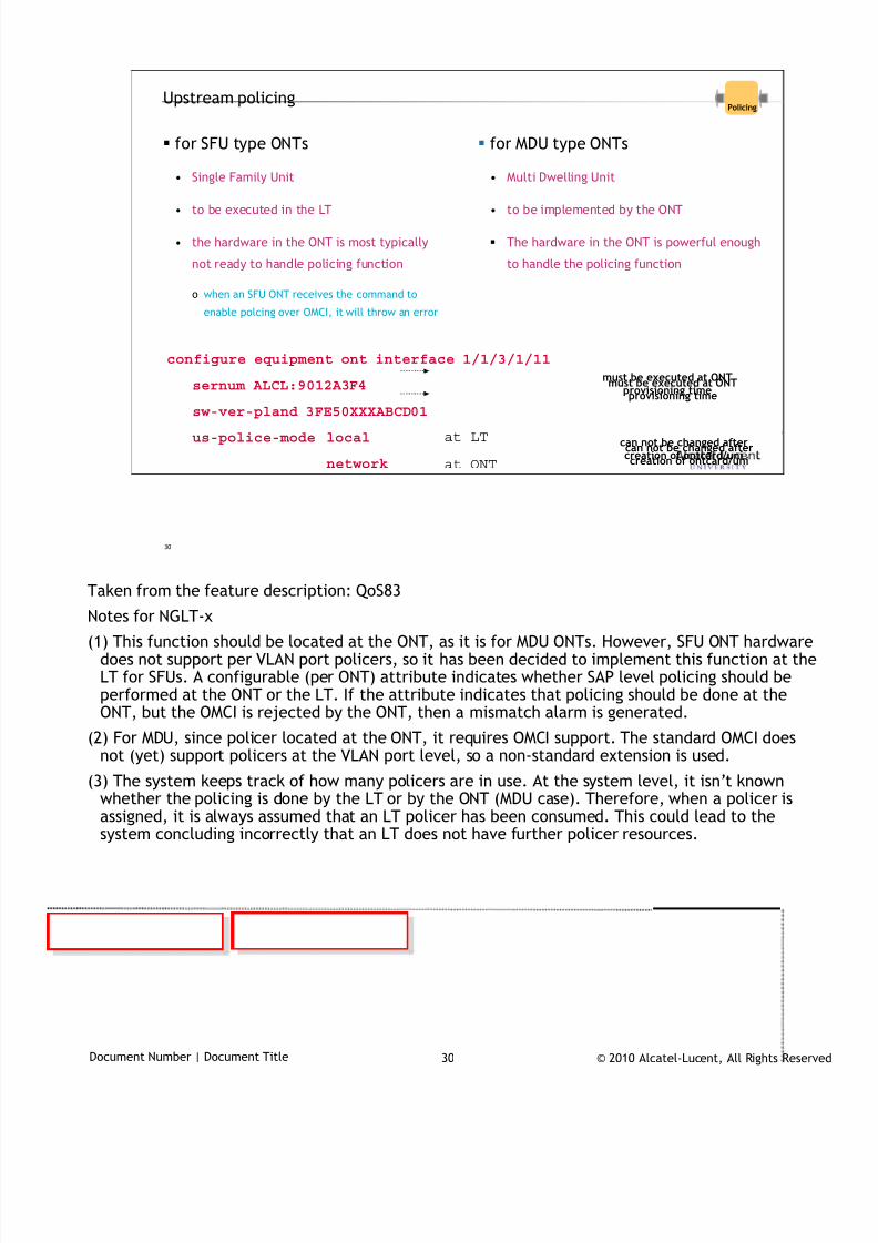
7/18/2019 Alu - A7302 Isam Fttu Operator Gpon Nant-e_ce-PDF
http://slidepdf.com/reader/full/alu-a7302-isam-fttu-operator-gpon-nant-ece-pdf 389/432
© 2010 Alcatel-Lucent, All Rights ReservedDocument Number | Document Title 30
30
Upstream policingPolicing
for SFU type ONTs
• Single Family Unit
• to be executed in the LT
• the hardware in the ONT is most typically
not ready to handle policing function
o when an SFU ONT receives the command to
enable polcing over OMCI, it will throw an error
for MDU type ONTs
• Multi Dwelling Unit
• to be implemented by the ONT
The hardware in the ONT is powerful enough
to handle the policing function
configure equipment ont interface 1/1/3/1/11
sernum ALCL:9012A3F4
sw-ver-pland 3FE50XXXABCD01
us-police-mode local
network
at LT
at ONT
can not be changed aftercreation of ontcard/uni
can not be changed aftercreation of ontcard/uni
must be executed at ONTprovisioning time
must be executed at ONTprovisioning time
Taken from the feature description: QoS83
Notes for NGLT-x
(1) This function should be located at the ONT, as it is for MDU ONTs. However, SFU ONT hardwaredoes not support per VLAN port policers, so it has been decided to implement this function at theLT for SFUs. A configurable (per ONT) attribute indicates whether SAP level policing should beperformed at the ONT or the LT. If the attribute indicates that policing should be done at theONT, but the OMCI is rejected by the ONT, then a mismatch alarm is generated.
(2) For MDU, since policer located at the ONT, it requires OMCI support. The standard OMCI doesnot (yet) support policers at the VLAN port level, so a non-standard extension is used.
(3) The system keeps track of how many policers are in use. At the system level, it isn’t knownwhether the policing is done by the LT or by the ONT (MDU case). Therefore, when a policer isassigned, it is always assumed that an LT policer has been consumed. This could lead to thesystem concluding incorrectly that an LT does not have further policer resources.
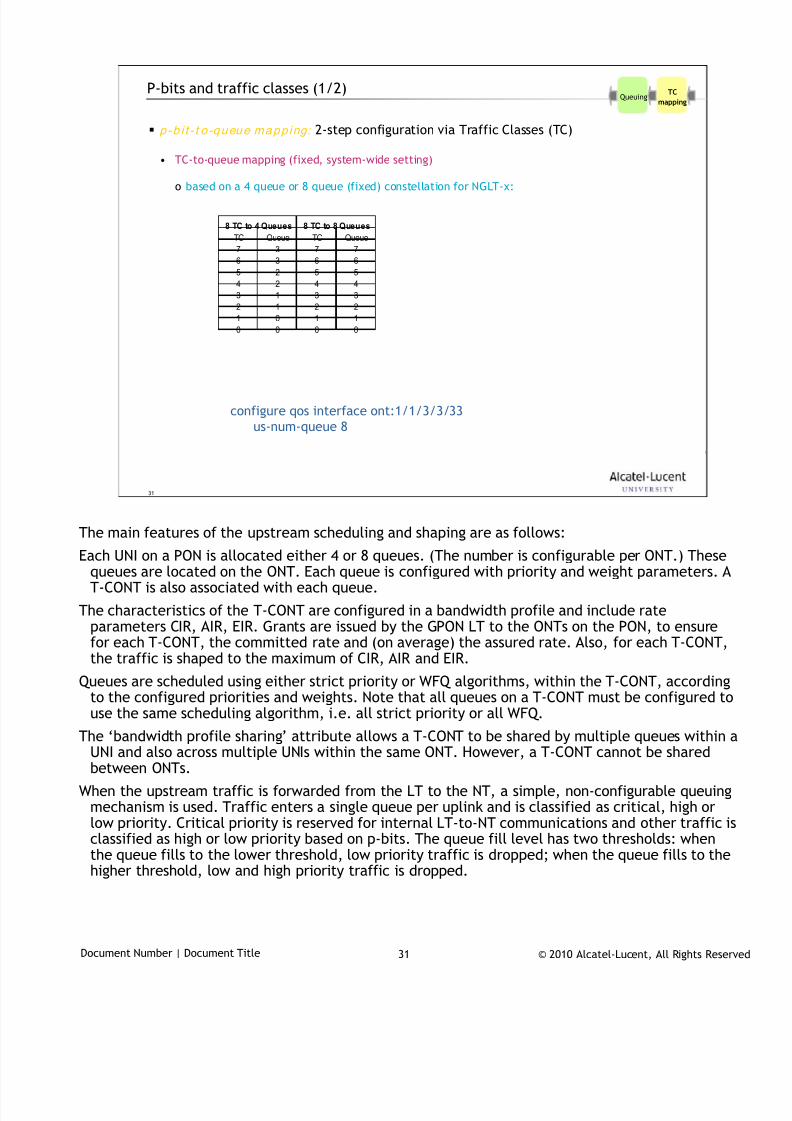
7/18/2019 Alu - A7302 Isam Fttu Operator Gpon Nant-e_ce-PDF
http://slidepdf.com/reader/full/alu-a7302-isam-fttu-operator-gpon-nant-ece-pdf 390/432
© 2010 Alcatel-Lucent, All Rights ReservedDocument Number | Document Title 31
31
P-bits and traffic classes (1/2)
p-b i t - t o -queue mapp ing: 2-step configuration via Traffic Classes (TC)
• TC-to-queue mapping (fixed, system-wide setting)
o based on a 4 queue or 8 queue (fixed) constellation for NGLT-x:
TC Queue TC Queue
7 3 7 7
6 3 6 6
5 2 5 5
4 2 4 4
3 1 3 3
2 1 2 2
1 0 1 1
0 0 0 0
8 TC to 4 Queues 8 TC to 8 Queues
TC
mappingQueuing
configure qos interface ont:1/1/3/3/33
us-num-queue 8
The main features of the upstream scheduling and shaping are as follows:
Each UNI on a PON is allocated either 4 or 8 queues. (The number is configurable per ONT.) Thesequeues are located on the ONT. Each queue is configured with priority and weight parameters. AT-CONT is also associated with each queue.
The characteristics of the T-CONT are configured in a bandwidth profile and include rateparameters CIR, AIR, EIR. Grants are issued by the GPON LT to the ONTs on the PON, to ensurefor each T-CONT, the committed rate and (on average) the assured rate. Also, for each T-CONT,the traffic is shaped to the maximum of CIR, AIR and EIR.
Queues are scheduled using either strict priority or WFQ algorithms, within the T-CONT, accordingto the configured priorities and weights. Note that all queues on a T-CONT must be configured touse the same scheduling algorithm, i.e. all strict priority or all WFQ.
The ‘bandwidth profile sharing’ attribute allows a T-CONT to be shared by multiple queues within aUNI and also across multiple UNIs within the same ONT. However, a T-CONT cannot be sharedbetween ONTs.
When the upstream traffic is forwarded from the LT to the NT, a simple, non-configurable queuingmechanism is used. Traffic enters a single queue per uplink and is classified as critical, high orlow priority. Critical priority is reserved for internal LT-to-NT communications and other traffic isclassified as high or low priority based on p-bits. The queue fill level has two thresholds: whenthe queue fills to the lower threshold, low priority traffic is dropped; when the queue fills to thehigher threshold, low and high priority traffic is dropped.
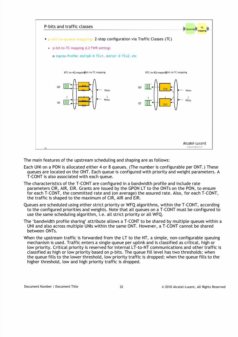
7/18/2019 Alu - A7302 Isam Fttu Operator Gpon Nant-e_ce-PDF
http://slidepdf.com/reader/full/alu-a7302-isam-fttu-operator-gpon-nant-ece-pdf 391/432
© 2010 Alcatel-Lucent, All Rights ReservedDocument Number | Document Title 32
32
P-bits and traffic classes
p-b i t - t o -queue mapp ing: 2-step configuration via Traffic Classes (TC)
• p-bit-to-TC mapping (L2 FWR setting)
o ingress Profile: dot1p0 TCx1, dot1p1 TCx2, etc
QO
Q7
…
TC0
TC7
…
8TC-to-8Q mappingPbit-to-TC mapping
Pbitx
Pbitz
…
QO
Q4
…
8TC-to-4Q mappingPbit-to-TC mapping
Pbitx
Pbitz
TC1
TC7
…
TC0
TC6
…
TC
mappingQueuing
The main features of the upstream scheduling and shaping are as follows:
Each UNI on a PON is allocated either 4 or 8 queues. (The number is configurable per ONT.) Thesequeues are located on the ONT. Each queue is configured with priority and weight parameters. AT-CONT is also associated with each queue.
The characteristics of the T-CONT are configured in a bandwidth profile and include rateparameters CIR, AIR, EIR. Grants are issued by the GPON LT to the ONTs on the PON, to ensurefor each T-CONT, the committed rate and (on average) the assured rate. Also, for each T-CONT,the traffic is shaped to the maximum of CIR, AIR and EIR.
Queues are scheduled using either strict priority or WFQ algorithms, within the T-CONT, accordingto the configured priorities and weights. Note that all queues on a T-CONT must be configured touse the same scheduling algorithm, i.e. all strict priority or all WFQ.
The ‘bandwidth profile sharing’ attribute allows a T-CONT to be shared by multiple queues within aUNI and also across multiple UNIs within the same ONT. However, a T-CONT cannot be sharedbetween ONTs.
When the upstream traffic is forwarded from the LT to the NT, a simple, non-configurable queuingmechanism is used. Traffic enters a single queue per uplink and is classified as critical, high orlow priority. Critical priority is reserved for internal LT-to-NT communications and other traffic isclassified as high or low priority based on p-bits. The queue fill level has two thresholds: whenthe queue fills to the lower threshold, low priority traffic is dropped; when the queue fills to thehigher threshold, low and high priority traffic is dropped.
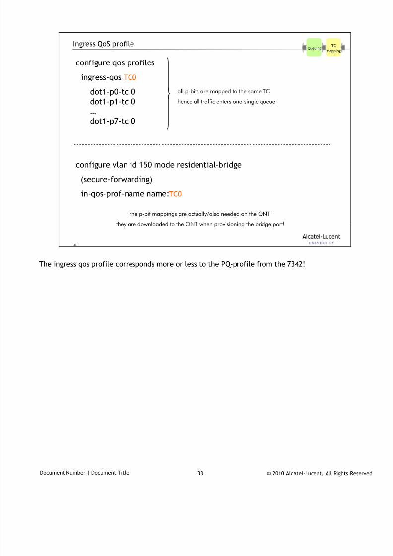
7/18/2019 Alu - A7302 Isam Fttu Operator Gpon Nant-e_ce-PDF
http://slidepdf.com/reader/full/alu-a7302-isam-fttu-operator-gpon-nant-ece-pdf 392/432
© 2010 Alcatel-Lucent, All Rights ReservedDocument Number | Document Title 33
33
Ingress QoS profile
configure qos profiles
ingress-qos TC0
dot1-p0-tc 0dot1-p1-tc 0
…
dot1-p7-tc 0
configure vlan id 150 mode residential-bridge
(secure-forwarding)
in-qos-prof-name name:TC0
all p-bits are mapped to the same TC
hence all traffic enters one single queue
the p-bit mappings are actually/also needed on the ONT
they are downloaded to the ONT when provisioning the bridge port!
TC
mappingQueuing
The ingress qos profile corresponds more or less to the PQ-profile from the 7342!
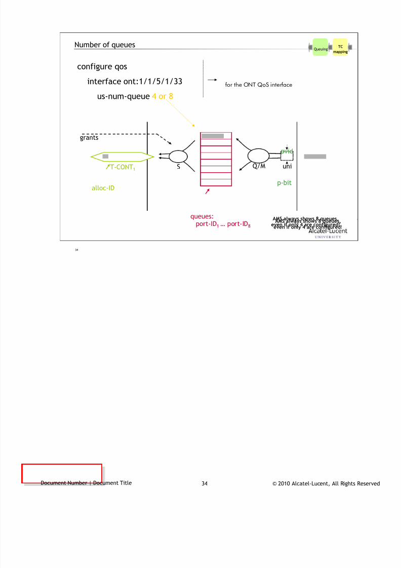
7/18/2019 Alu - A7302 Isam Fttu Operator Gpon Nant-e_ce-PDF
http://slidepdf.com/reader/full/alu-a7302-isam-fttu-operator-gpon-nant-ece-pdf 393/432
© 2010 Alcatel-Lucent, All Rights ReservedDocument Number | Document Title 34
34
Number of queues
configure qos
interface ont:1/1/5/1/33
us-num-queue 4 or 8
for the ONT QoS interface
TC
mappingQueuing
T-CONT1uni
pvid
p-bit
grants
alloc-ID
port-ID1 … port-ID8
Q/MS
queues:AMS always shows 8 queues,
even if only 4 are configured!
AMS always shows 8 queues,even if only 4 are configured!

7/18/2019 Alu - A7302 Isam Fttu Operator Gpon Nant-e_ce-PDF
http://slidepdf.com/reader/full/alu-a7302-isam-fttu-operator-gpon-nant-ece-pdf 394/432
© 2010 Alcatel-Lucent, All Rights ReservedDocument Number | Document Title 35
35
QoS architecture… LT + ONT downstream6
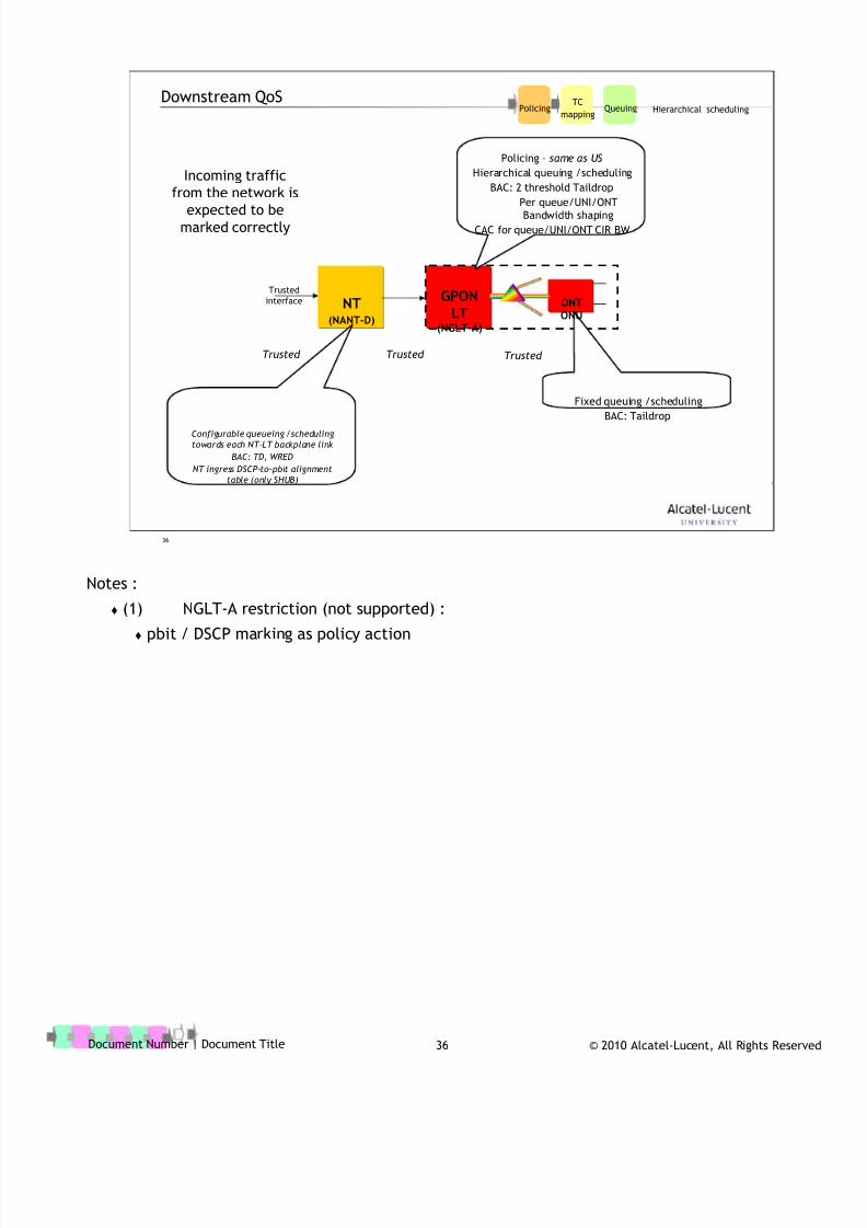
7/18/2019 Alu - A7302 Isam Fttu Operator Gpon Nant-e_ce-PDF
http://slidepdf.com/reader/full/alu-a7302-isam-fttu-operator-gpon-nant-ece-pdf 395/432
© 2010 Alcatel-Lucent, All Rights ReservedDocument Number | Document Title 36
36
Downstream QoS
NT(NANT-D)
GPONLT
(NGLT-A)
ONTONU
Trusted
interface
Trusted Trusted Trusted
Policing – same as US
Hierarchical queuing /scheduling
BAC: 2 threshold Taildrop
Per queue/UNI/ONTBandwidth shaping
CAC for queue/UNI/ONT CIR BW
Fixed queuing /schedulingBAC: Taildrop
Configurable queueing /scheduling
towards each NT-LT backplane link
BAC: TD, WRED
NT ingress DSCP-to-pbit alignment
table (only SHUB)
Incoming traffic
from the network isexpected to be
marked correctly
PolicingTC
mappingQueuing Hierarchical scheduling
Notes :
(1) NGLT-A restriction (not supported) :
pbit / DSCP marking as policy action
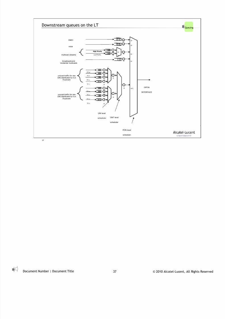
7/18/2019 Alu - A7302 Isam Fttu Operator Gpon Nant-e_ce-PDF
http://slidepdf.com/reader/full/alu-a7302-isam-fttu-operator-gpon-nant-ece-pdf 396/432
© 2010 Alcatel-Lucent, All Rights ReservedDocument Number | Document Title 37
37
Downstream queues on the LT
GPON
INTERFACE
OMCI
SP
Voice
SP
WFQ
R
TC x
TC y
TC z
R
R
R
R
R
TC w R
TC x
TC y
TC z
R
R
R
R
TC w R
Low Priority R
High Priority R
R
R
SPRbroadcasts andincidental multicasts
multicast streams
unicast traffic for oneUNI distributed to 4 or
8 queues
unicast traffic for oneUNI distributed to 4 or
8 queues
UNI level
scheduler ONT level
scheduler
PON level
scheduler
OMCI
voice
SP
SP
SP
Queuing
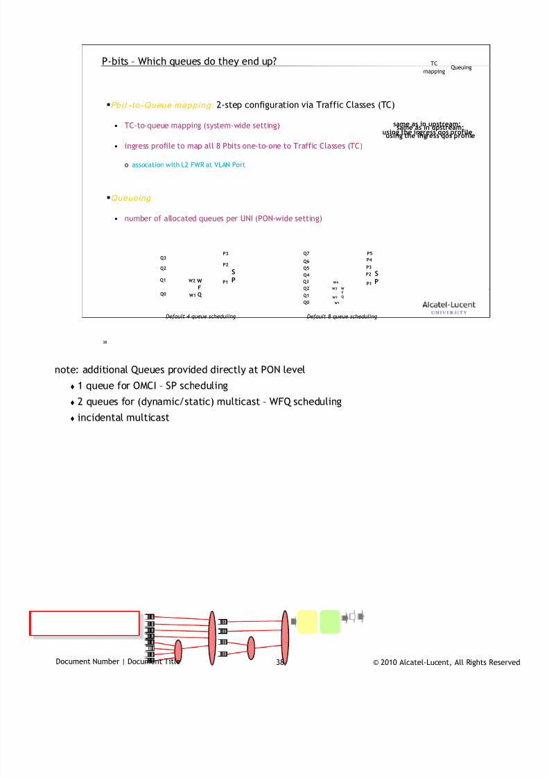
7/18/2019 Alu - A7302 Isam Fttu Operator Gpon Nant-e_ce-PDF
http://slidepdf.com/reader/full/alu-a7302-isam-fttu-operator-gpon-nant-ece-pdf 397/432
© 2010 Alcatel-Lucent, All Rights ReservedDocument Number | Document Title 38
38
P-bits – Which queues do they end up?
Pbi t - to-Queue mapping: 2-step configuration via Traffic Classes (TC)
• TC-to-queue mapping (system-wide setting)
• ingress profile to map all 8 Pbits one-to-one to Traffic Classes (TC)
o assocation with L2 FWR at VLAN Port
Queueing
• number of allocated queues per UNI (PON-wide setting)
same as in upstream:using the ingress qos profile
same as in upstream:using the ingress qos profile
TC
mappingQueuing
SP
Q3
Q2
Q1
Q0
P2
P3
WFQ
P1
W1
W2
Default 4 queue scheduling
SP
Q6
Q5
Q3
Q1
P2
P3
WFQ
P1
W1
W4
Q0
Q2
Q4
Q7
W2
W3
P4P5
Default 8 queue scheduling
note: additional Queues provided directly at PON level
1 queue for OMCI – SP scheduling
2 queues for (dynamic/static) multicast – WFQ scheduling
incidental multicast
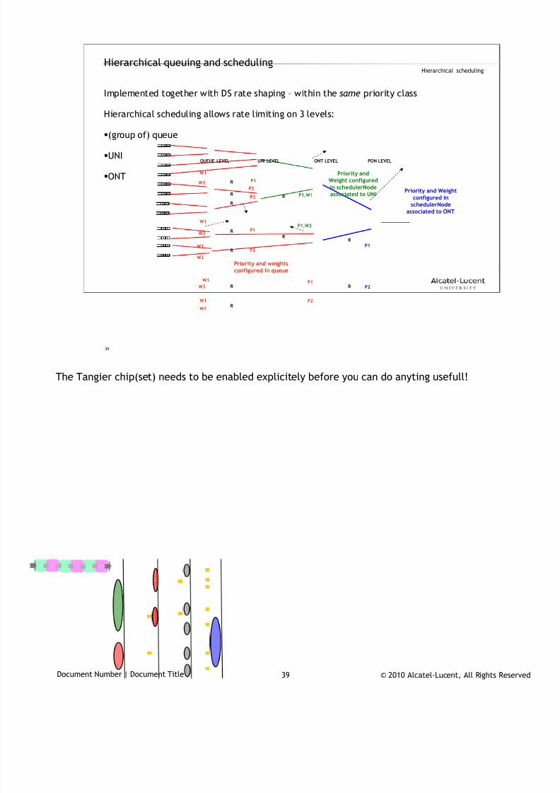
7/18/2019 Alu - A7302 Isam Fttu Operator Gpon Nant-e_ce-PDF
http://slidepdf.com/reader/full/alu-a7302-isam-fttu-operator-gpon-nant-ece-pdf 398/432
© 2010 Alcatel-Lucent, All Rights ReservedDocument Number | Document Title 39
39
Hierarchical queuing and scheduling
Implemented together with DS rate shaping – within the same priority class
Hierarchical scheduling allows rate limiting on 3 levels:
(group of) queue
UNI
ONT
UNI LEVEL ONT LEVEL PON LEVEL
W2
W1
P1
P2
P3
W1
W2
W1
W2
W1
W2
W1
W2
P1
P2
P1
P2
P1,W1
P1,W2
Priority and weightsconfigured in queue
Priority andWeight configuredin schedulerNodeassociated to UNI
P1
P2
QUEUE LEVEL
Priority and Weightconfigured in
schedulerNodeassociated to ONT
R
R
R
R
R
R
R
R
R
R
R
Hierarchical scheduling
The Tangier chip(set) needs to be enabled explicitely before you can do anyting usefull!
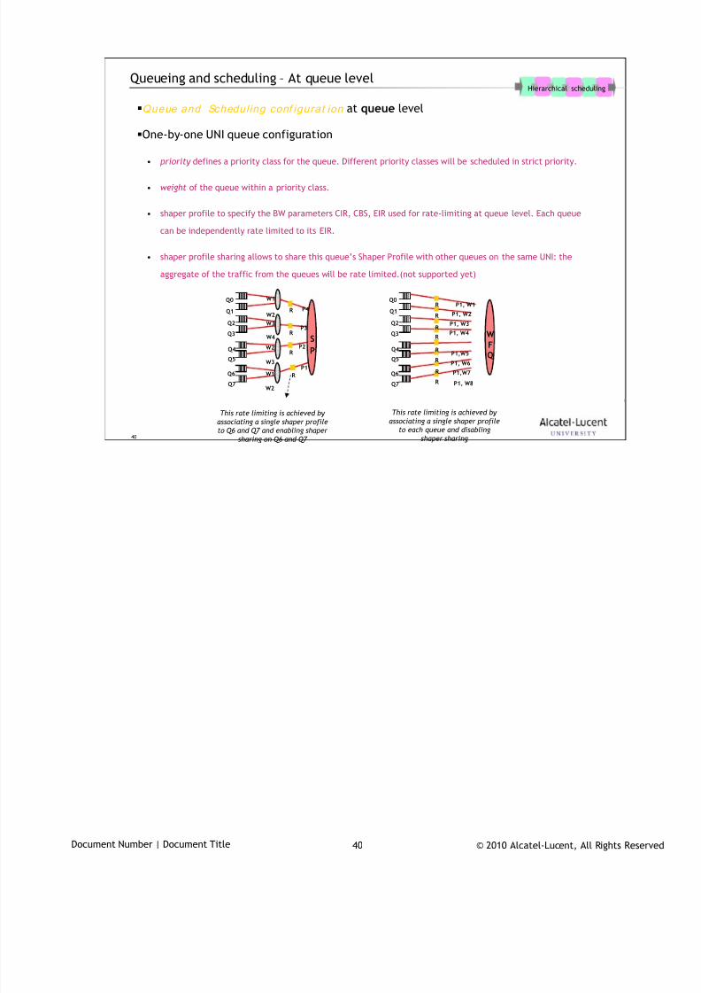
7/18/2019 Alu - A7302 Isam Fttu Operator Gpon Nant-e_ce-PDF
http://slidepdf.com/reader/full/alu-a7302-isam-fttu-operator-gpon-nant-ece-pdf 399/432
© 2010 Alcatel-Lucent, All Rights ReservedDocument Number | Document Title 40
40
Queueing and scheduling – At queue level
Queue and Schedul ing conf igurat ion at queue level
One-by-one UNI queue configuration
• priority defines a priority class for the queue. Different priority classes will be scheduled in strict priority.
• weight of the queue within a priority class.
• shaper profile to specify the BW parameters CIR, CBS, EIR used for rate-limiting at queue level. Each queue
can be independently rate limited to its EIR.
• shaper profile sharing allows to share this queue’s Shaper Profile with other queues on the same UNI: the
aggregate of the traffic from the queues will be rate limited.(not supported yet)
S
P
R
R
R
R
W1
W2
W3
W4
W2
W3
W1
W2
P4
P3
P2
P1
Q0
Q1
Q2
Q3
Q4
Q5
Q6
Q7
This rate limiting is achieved by
associating a single shaper profile
to Q6 and Q7 and enabling shaper
sharing on Q6 and Q7
WFQ
Q0
Q1
Q2
Q3
Q4
Q5
Q6
Q7
R
R
R
R
R
R
R
R
P1, W1
P1,W7
P1, W8
P1, W2
P1, W3
P1, W4
P1,W5
P1, W6
This rate limiting is achieved by
associating a single shaper profile
to each queue and disabling
shaper sharing
Hierarchical scheduling
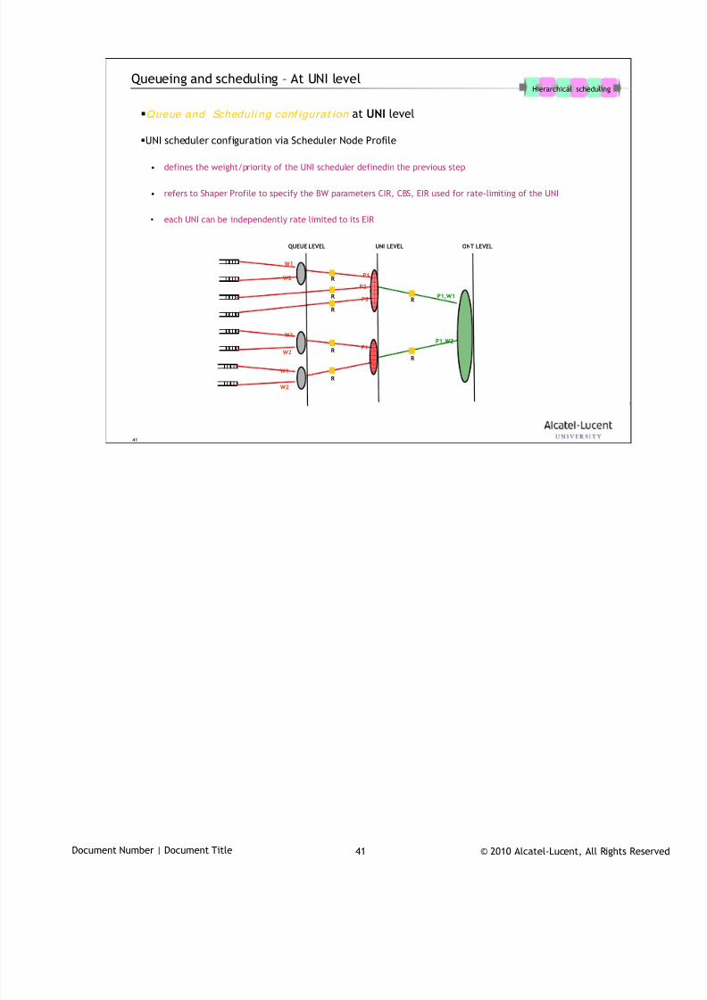
7/18/2019 Alu - A7302 Isam Fttu Operator Gpon Nant-e_ce-PDF
http://slidepdf.com/reader/full/alu-a7302-isam-fttu-operator-gpon-nant-ece-pdf 400/432
© 2010 Alcatel-Lucent, All Rights ReservedDocument Number | Document Title 41
41
Queueing and scheduling – At UNI level
Queue and Schedul i ng conf igurat ion at UNI level
UNI scheduler configuration via Scheduler Node Profile
• defines the weight/priority of the UNI scheduler definedin the previous step
• refers to Shaper Profile to specify the BW parameters CIR, CBS, EIR used for rate-limiting of the UNI
• each UNI can be independently rate limited to its EIR
Hierarchical scheduling
UNI LEVEL ONT LEVEL
W2
W1
P1
P2
P3
W1
W2
W1
W2
P1,W1
P1,W2P1
QUEUE LEVEL
R
R
R
R
R
R
R
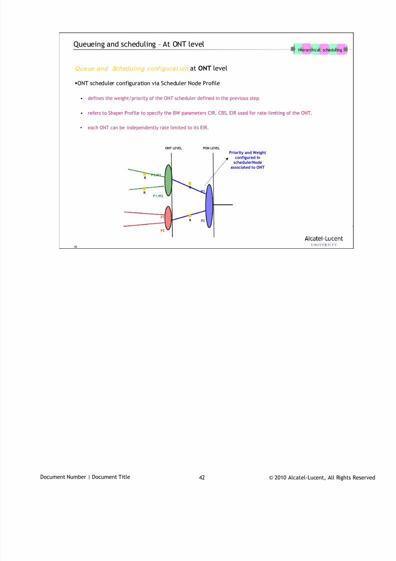
7/18/2019 Alu - A7302 Isam Fttu Operator Gpon Nant-e_ce-PDF
http://slidepdf.com/reader/full/alu-a7302-isam-fttu-operator-gpon-nant-ece-pdf 401/432
© 2010 Alcatel-Lucent, All Rights ReservedDocument Number | Document Title 42
42
Queueing and scheduling – At ONT level
Queue and Schedul ing conf igurat ion at ONT level
ONT scheduler configuration via Scheduler Node Profile
• defines the weight/priority of the ONT scheduler defined in the previous step
• refers to Shaper Profile to specify the BW parameters CIR, CBS, EIR used for rate-limiting of the ONT.
• each ONT can be independently rate limited to its EIR.
Hierarchical scheduling
ONT LEVEL PON LEVEL
P1
P2
P1
P2
P1,W1
P1,W2
Priority and Weightconfigured in
schedulerNodeassociated to ONT
R
R
R
R
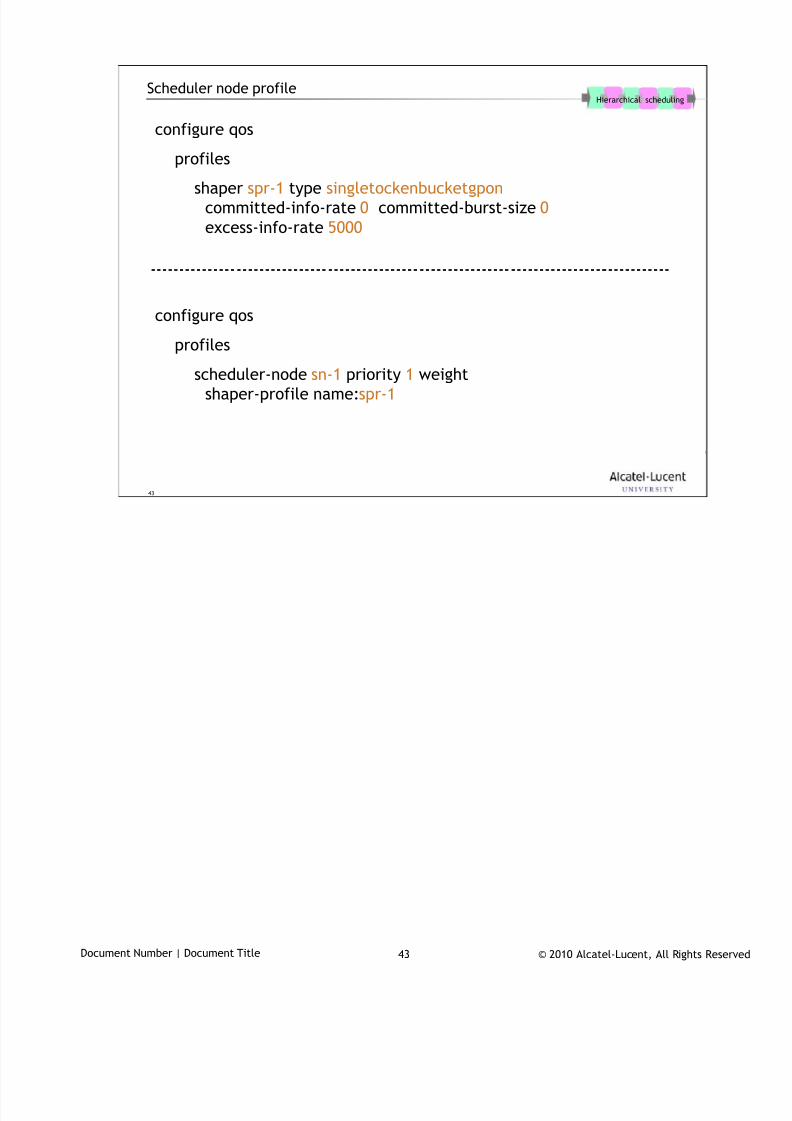
7/18/2019 Alu - A7302 Isam Fttu Operator Gpon Nant-e_ce-PDF
http://slidepdf.com/reader/full/alu-a7302-isam-fttu-operator-gpon-nant-ece-pdf 402/432
© 2010 Alcatel-Lucent, All Rights ReservedDocument Number | Document Title 43
43
Scheduler node profile
configure qos
profiles
shaper spr-1 type singletockenbucketgponcommitted-info-rate 0 committed-burst-size 0
excess-info-rate 5000
configure qos
profiles
scheduler-node sn-1 priority 1 weight
shaper-profile name:spr-1
Hierarchical scheduling

7/18/2019 Alu - A7302 Isam Fttu Operator Gpon Nant-e_ce-PDF
http://slidepdf.com/reader/full/alu-a7302-isam-fttu-operator-gpon-nant-ece-pdf 403/432
© 2010 Alcatel-Lucent, All Rights ReservedDocument Number | Document Title 44
44
www.alcatel-lucent.comwww.alcatel-lucent.com
7/18/2019 Alu - A7302 Isam Fttu Operator Gpon Nant-e_ce-PDF
http://slidepdf.com/reader/full/alu-a7302-isam-fttu-operator-gpon-nant-ece-pdf 404/432
© 2010 Alcatel-Lucent, All Rights ReservedDocument Number | Document Title 1
Fault Management
During class please switch off your mobile, pager or other that may interrupt.
Fault management performs the following tasks:
collecting alarms
the alarm subsystem subscribes to alarm events (sent via an SNMP trap).
presenting alarms
current alarms are displayed in the current alarm list. Archived alarms are displayed inthe historical alarm list. Filters can be applied. Several alarm view can be displayedin parallel.

7/18/2019 Alu - A7302 Isam Fttu Operator Gpon Nant-e_ce-PDF
http://slidepdf.com/reader/full/alu-a7302-isam-fttu-operator-gpon-nant-ece-pdf 405/432
© 2010 Alcatel-Lucent, All Rights ReservedDocument Number | Document Title 2
Objective
After completing this section, you’ll be able to:
• describe how alarms are handled by the NE and the AMS
• overrule the alarm reporting mode on the NE for a specific port
• retrieve the alarm severity assignment table on NE
• retrieve a list of current alarms (NE or object level)
• retrieve detailed information for a specific alarm
• describe the different actions that can be performed on an alarm
• perform actions on a alarm (acknowledge, assign to …)
• move an alarm to the historical alarm list
• create a filter for an alarm view and activate it

7/18/2019 Alu - A7302 Isam Fttu Operator Gpon Nant-e_ce-PDF
http://slidepdf.com/reader/full/alu-a7302-isam-fttu-operator-gpon-nant-ece-pdf 406/432
© 2010 Alcatel-Lucent, All Rights ReservedDocument Number | Document Title 3
3
Table of Contents
1. Concepts
2. Network Perspective
3. Alarm Perspective
Agenda Pages
This page allows for the listing of the sections within a presentation.

7/18/2019 Alu - A7302 Isam Fttu Operator Gpon Nant-e_ce-PDF
http://slidepdf.com/reader/full/alu-a7302-isam-fttu-operator-gpon-nant-ece-pdf 407/432
© 2010 Alcatel-Lucent, All Rights ReservedDocument Number | Document Title 4
4
Concepts1
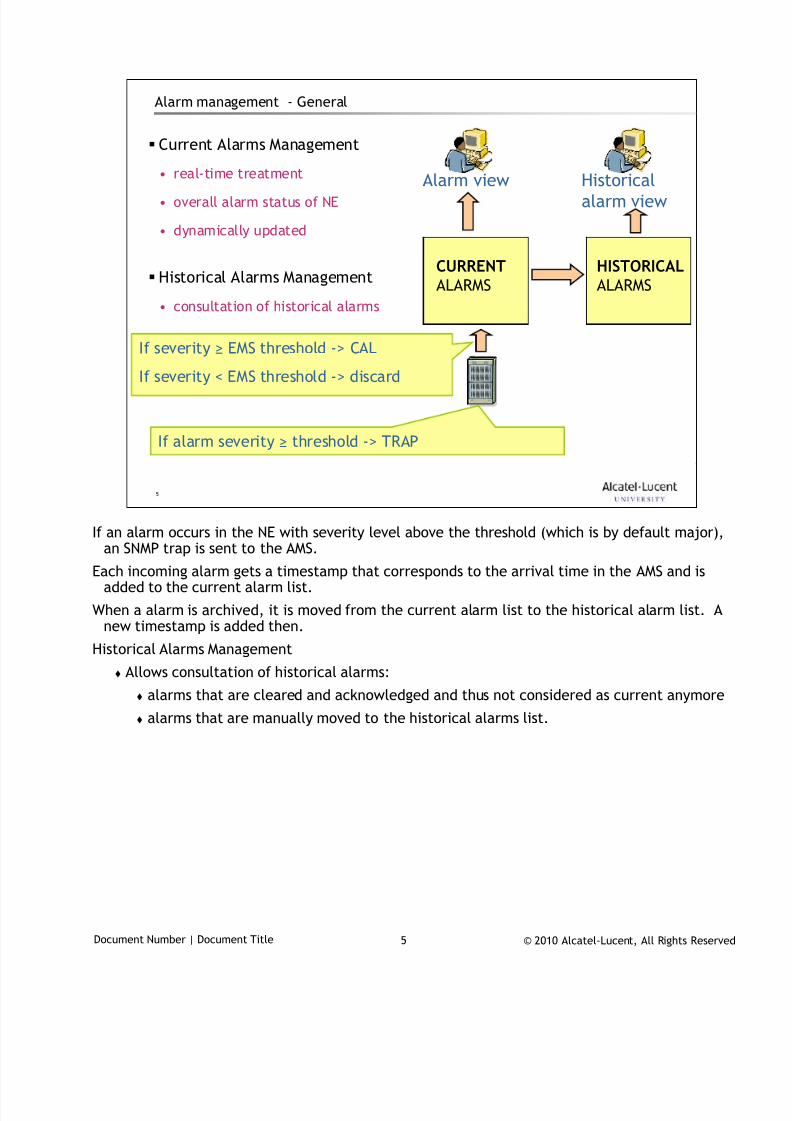
7/18/2019 Alu - A7302 Isam Fttu Operator Gpon Nant-e_ce-PDF
http://slidepdf.com/reader/full/alu-a7302-isam-fttu-operator-gpon-nant-ece-pdf 408/432
© 2010 Alcatel-Lucent, All Rights ReservedDocument Number | Document Title 5
5
Alarm management - General
Current Alarms Management
• real-time treatment
• overall alarm status of NE
• dynamically updated
Historical Alarms Management
• consultation of historical alarms
CURRENTALARMS
HISTORICALALARMS
Alarm view Historicalalarm view
If alarm severity ≥ threshold -> TRAP
If severity ≥ EMS threshold -> CAL
If severity < EMS threshold -> discard
If an alarm occurs in the NE with severity level above the threshold (which is by default major),
an SNMP trap is sent to the AMS.
Each incoming alarm gets a timestamp that corresponds to the arrival time in the AMS and isadded to the current alarm list.
When a alarm is archived, it is moved from the current alarm list to the historical alarm list. Anew timestamp is added then.
Historical Alarms Management
Allows consultation of historical alarms:
alarms that are cleared and acknowledged and thus not considered as current anymore
alarms that are manually moved to the historical alarms list.
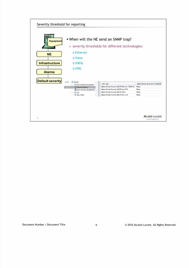
7/18/2019 Alu - A7302 Isam Fttu Operator Gpon Nant-e_ce-PDF
http://slidepdf.com/reader/full/alu-a7302-isam-fttu-operator-gpon-nant-ece-pdf 409/432
© 2010 Alcatel-Lucent, All Rights ReservedDocument Number | Document Title 6
6
Severity threshold for reporting
When will the NE send an SNMP trap?
• severity thresholds for different technologies:
o Ethernet
o Voice
o SHDSL
o XDSL
Equipment
Infrastructure
Alarms
Default severity
NE
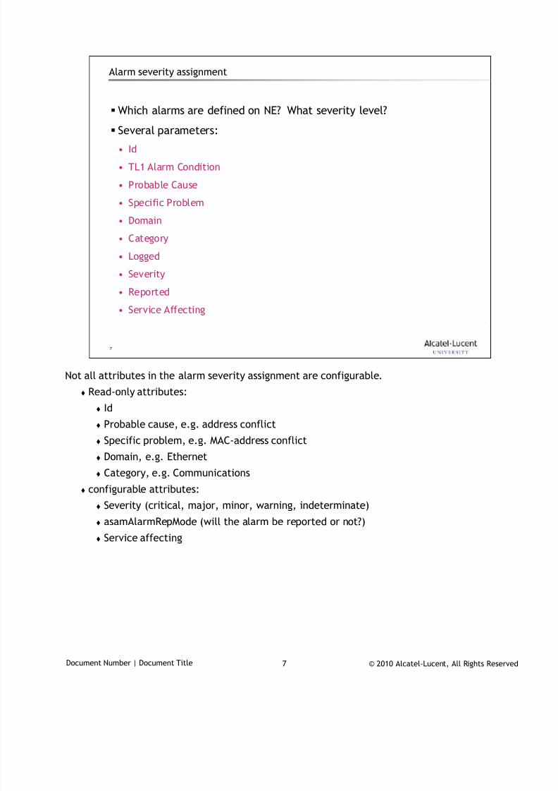
7/18/2019 Alu - A7302 Isam Fttu Operator Gpon Nant-e_ce-PDF
http://slidepdf.com/reader/full/alu-a7302-isam-fttu-operator-gpon-nant-ece-pdf 410/432
© 2010 Alcatel-Lucent, All Rights ReservedDocument Number | Document Title 7
7
Alarm severity assignment
Which alarms are defined on NE? What severity level?
Several parameters:
• Id
• TL1 Alarm Condition
• Probable Cause
• Specific Problem
• Domain
• Category
• Logged
• Severity
• Reported
• Service Affecting
Not all attributes in the alarm severity assignment are configurable.
Read-only attributes:
Id
Probable cause, e.g. address conflict
Specific problem, e.g. MAC-address conflict
Domain, e.g. Ethernet
Category, e.g. Communications
configurable attributes:
Severity (critical, major, minor, warning, indeterminate)
asamAlarmRepMode (will the alarm be reported or not?)
Service affecting
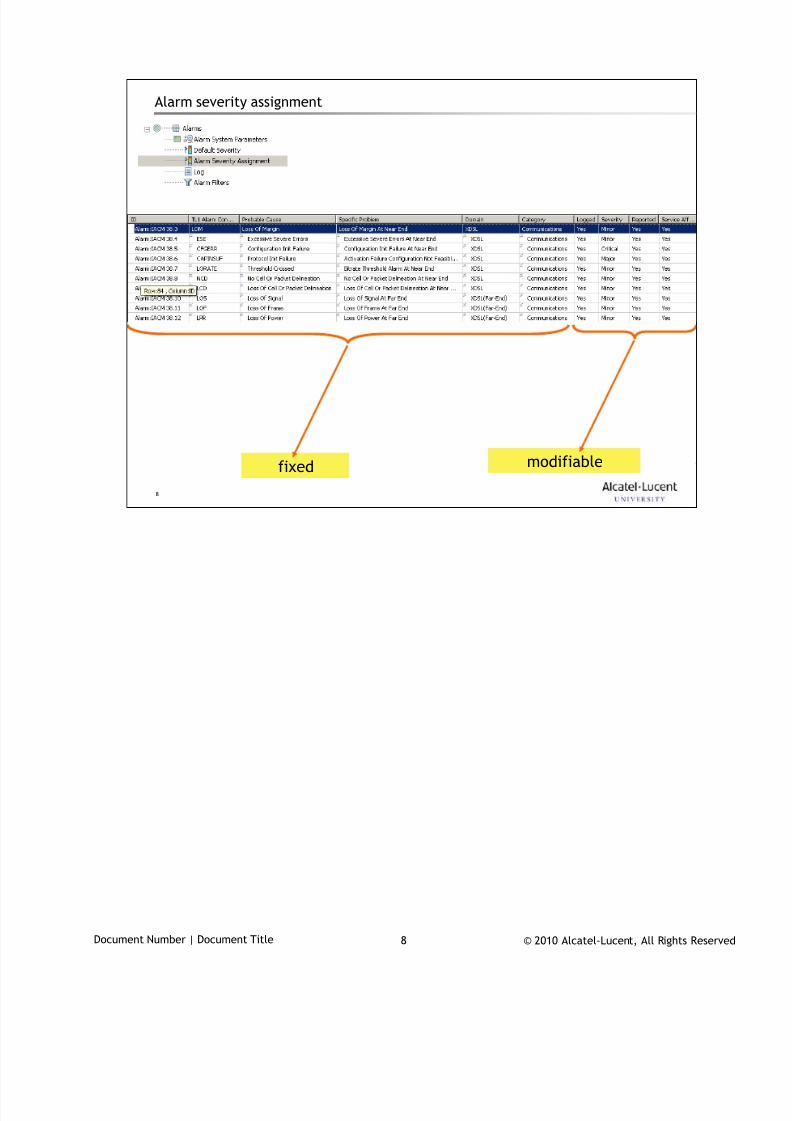
7/18/2019 Alu - A7302 Isam Fttu Operator Gpon Nant-e_ce-PDF
http://slidepdf.com/reader/full/alu-a7302-isam-fttu-operator-gpon-nant-ece-pdf 411/432
© 2010 Alcatel-Lucent, All Rights ReservedDocument Number | Document Title 8
8
Alarm severity assignment
modifiablefixed
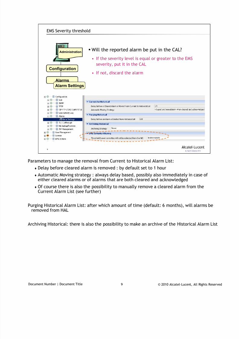
7/18/2019 Alu - A7302 Isam Fttu Operator Gpon Nant-e_ce-PDF
http://slidepdf.com/reader/full/alu-a7302-isam-fttu-operator-gpon-nant-ece-pdf 412/432
© 2010 Alcatel-Lucent, All Rights ReservedDocument Number | Document Title 9
9
EMS Severity threshold
Will the reported alarm be put in the CAL?
• If the severity level is equal or greater to the EMS
severity, put it in the CAL
• If not, discard the alarm
Administration
Alarms
Configuration
Alarm Settings
Parameters to manage the removal from Current to Historical Alarm List:
Delay before cleared alarm is removed : by default set to 1 hour
Automatic Moving strategy : always delay based, possibly also immediately in case ofeither cleared alarms or of alarms that are both cleared and acknowledged
Of course there is also the possibility to manually remove a cleared alarm from theCurrent Alarm List (see further)
Purging Historical Alarm List: after which amount of time (default: 6 months), will alarms beremoved from HAL
Archiving Historical: there is also the possibility to make an archive of the Historical Alarm List

7/18/2019 Alu - A7302 Isam Fttu Operator Gpon Nant-e_ce-PDF
http://slidepdf.com/reader/full/alu-a7302-isam-fttu-operator-gpon-nant-ece-pdf 413/432
© 2010 Alcatel-Lucent, All Rights ReservedDocument Number | Document Title 10
10
Network Perspective2
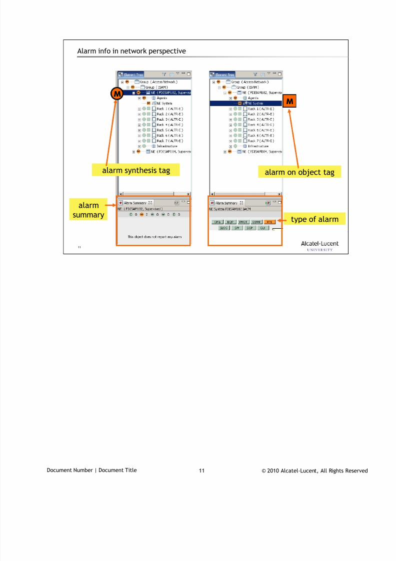
7/18/2019 Alu - A7302 Isam Fttu Operator Gpon Nant-e_ce-PDF
http://slidepdf.com/reader/full/alu-a7302-isam-fttu-operator-gpon-nant-ece-pdf 414/432
© 2010 Alcatel-Lucent, All Rights ReservedDocument Number | Document Title 11
11
Alarm info in network perspective
M
M
alarm on object tagalarm synthesis tag
type of alarm
alarm
summary
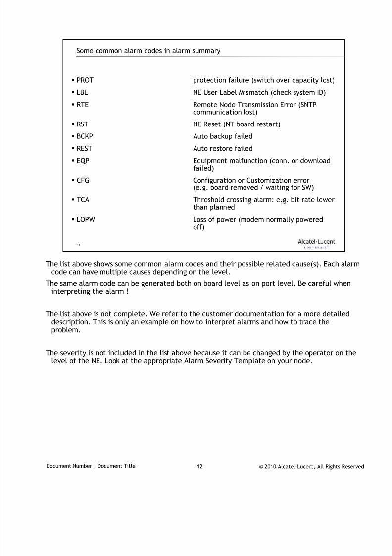
7/18/2019 Alu - A7302 Isam Fttu Operator Gpon Nant-e_ce-PDF
http://slidepdf.com/reader/full/alu-a7302-isam-fttu-operator-gpon-nant-ece-pdf 415/432
© 2010 Alcatel-Lucent, All Rights ReservedDocument Number | Document Title 12
12
Some common alarm codes in alarm summary
PROT protection failure (switch over capacity lost)
LBL NE User Label Mismatch (check system ID)
RTE Remote Node Transmission Error (SNTPcommunication lost)
RST NE Reset (NT board restart)
BCKP Auto backup failed
REST Auto restore failed
EQP Equipment malfunction (conn. or downloadfailed)
CFG Configuration or Customization error(e.g. board removed / waiting for SW)
TCA Threshold crossing alarm: e.g. bit rate lowerthan planned
LOPW Loss of power (modem normally poweredoff)
The list above shows some common alarm codes and their possible related cause(s). Each alarm
code can have multiple causes depending on the level.
The same alarm code can be generated both on board level as on port level. Be careful wheninterpreting the alarm !
The list above is not complete. We refer to the customer documentation for a more detaileddescription. This is only an example on how to interpret alarms and how to trace theproblem.
The severity is not included in the list above because it can be changed by the operator on the
level of the NE. Look at the appropriate Alarm Severity Template on your node.
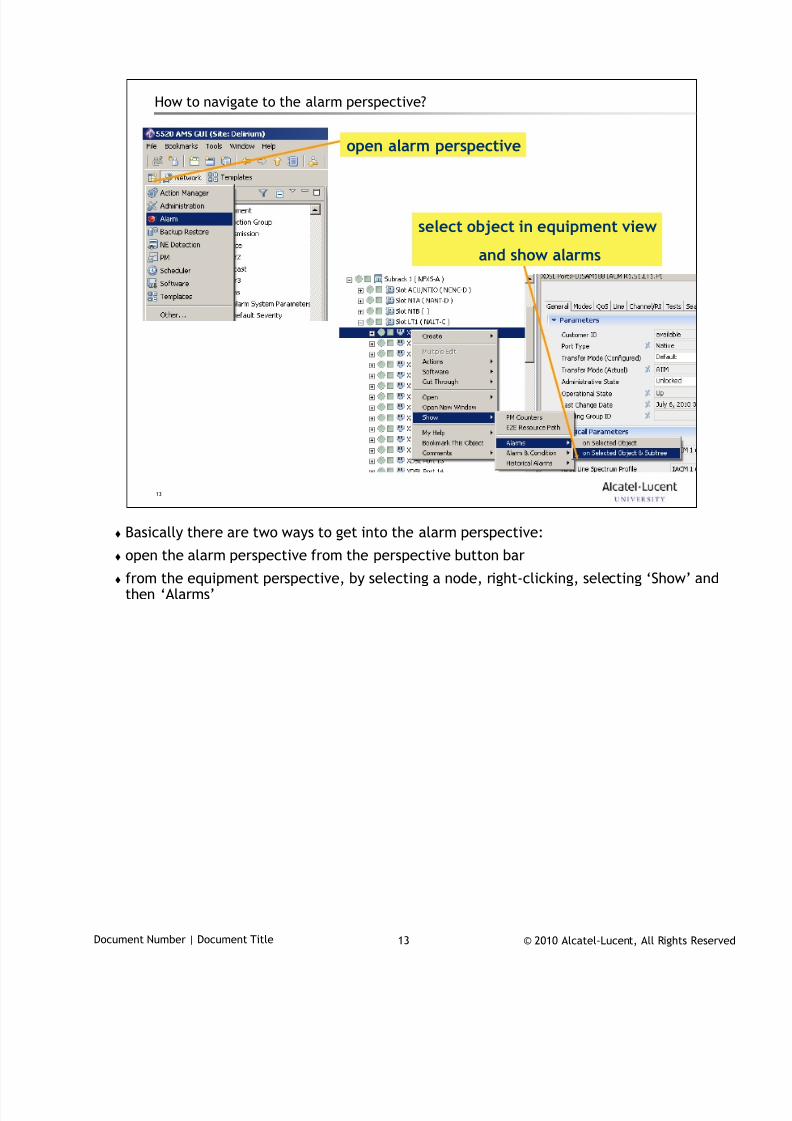
7/18/2019 Alu - A7302 Isam Fttu Operator Gpon Nant-e_ce-PDF
http://slidepdf.com/reader/full/alu-a7302-isam-fttu-operator-gpon-nant-ece-pdf 416/432
© 2010 Alcatel-Lucent, All Rights ReservedDocument Number | Document Title 13
13
How to navigate to the alarm perspective?
open alarm perspective
select object in equipment view
and show alarms
Basically there are two ways to get into the alarm perspective:
open the alarm perspective from the perspective button bar
from the equipment perspective, by selecting a node, right-clicking, selecting ‘Show’ andthen ‘Alarms’
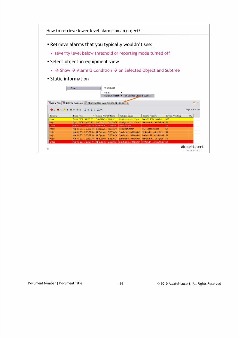
7/18/2019 Alu - A7302 Isam Fttu Operator Gpon Nant-e_ce-PDF
http://slidepdf.com/reader/full/alu-a7302-isam-fttu-operator-gpon-nant-ece-pdf 417/432
© 2010 Alcatel-Lucent, All Rights ReservedDocument Number | Document Title 14
14
How to retrieve lower level alarms on an object?
Retrieve alarms that you typically wouldn’t see:
• severity level below threshold or reporting mode turned off
Select object in equipment view
• Show Alarm & Condition on Selected Object and Subtree
Static information

7/18/2019 Alu - A7302 Isam Fttu Operator Gpon Nant-e_ce-PDF
http://slidepdf.com/reader/full/alu-a7302-isam-fttu-operator-gpon-nant-ece-pdf 418/432
© 2010 Alcatel-Lucent, All Rights ReservedDocument Number | Document Title 15
15
Alarm Perspective3
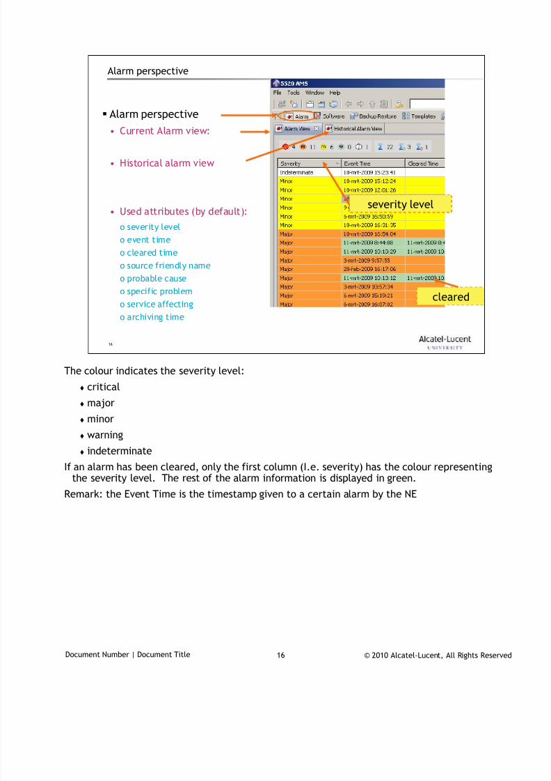
7/18/2019 Alu - A7302 Isam Fttu Operator Gpon Nant-e_ce-PDF
http://slidepdf.com/reader/full/alu-a7302-isam-fttu-operator-gpon-nant-ece-pdf 419/432
© 2010 Alcatel-Lucent, All Rights ReservedDocument Number | Document Title 16
16
Alarm perspective
Alarm perspective
• Current Alarm view:
• Historical alarm view
• Used attributes (by default):
o severity level
o event time
o cleared timeo source friendly name
o probable cause
o specific problem
o service affecting
o archiving time
cleared
severity level
The colour indicates the severity level:
critical
major
minor
warning
indeterminate
If an alarm has been cleared, only the first column (I.e. severity) has the colour representingthe severity level. The rest of the alarm information is displayed in green.
Remark: the Event Time is the timestamp given to a certain alarm by the NE
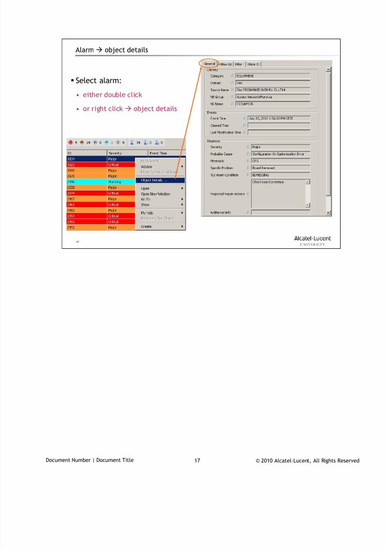
7/18/2019 Alu - A7302 Isam Fttu Operator Gpon Nant-e_ce-PDF
http://slidepdf.com/reader/full/alu-a7302-isam-fttu-operator-gpon-nant-ece-pdf 420/432
© 2010 Alcatel-Lucent, All Rights ReservedDocument Number | Document Title 17
17
Alarm object details
Select alarm:
• either double click
• or right click object details
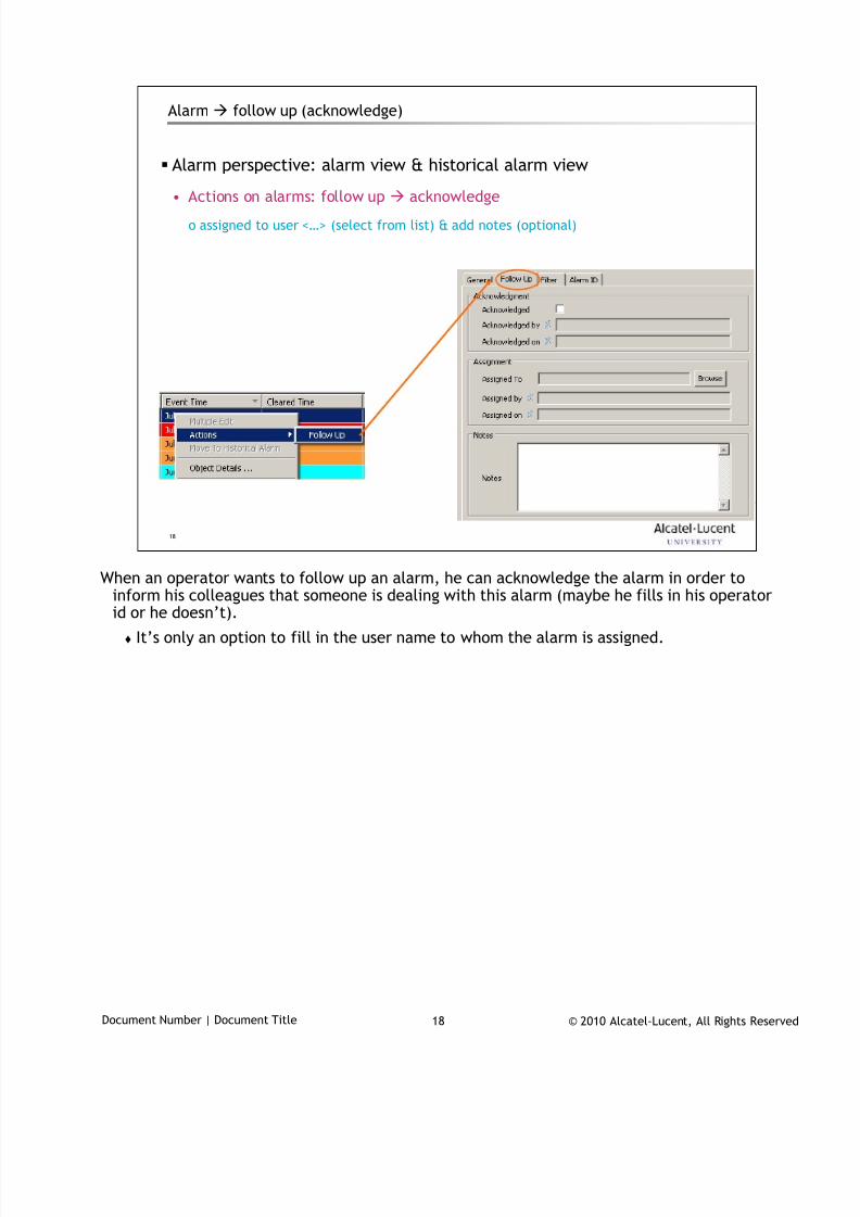
7/18/2019 Alu - A7302 Isam Fttu Operator Gpon Nant-e_ce-PDF
http://slidepdf.com/reader/full/alu-a7302-isam-fttu-operator-gpon-nant-ece-pdf 421/432
© 2010 Alcatel-Lucent, All Rights ReservedDocument Number | Document Title 18
18
Alarm follow up (acknowledge)
Alarm perspective: alarm view & historical alarm view
• Actions on alarms: follow up acknowledge
o assigned to user <…> (select from list) & add notes (optional)
When an operator wants to follow up an alarm, he can acknowledge the alarm in order to
inform his colleagues that someone is dealing with this alarm (maybe he fills in his operatorid or he doesn’t).
It’s only an option to fill in the user name to whom the alarm is assigned.
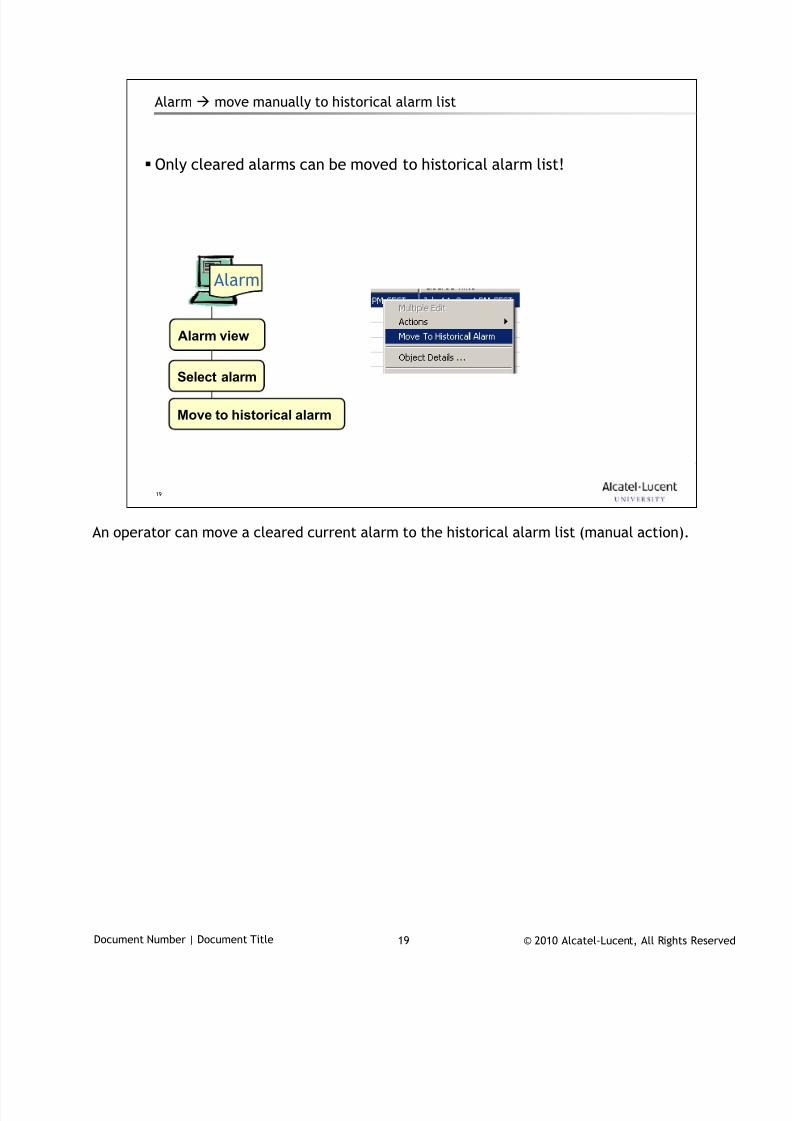
7/18/2019 Alu - A7302 Isam Fttu Operator Gpon Nant-e_ce-PDF
http://slidepdf.com/reader/full/alu-a7302-isam-fttu-operator-gpon-nant-ece-pdf 422/432
© 2010 Alcatel-Lucent, All Rights ReservedDocument Number | Document Title 19
19
Alarm move manually to historical alarm list
Only cleared alarms can be moved to historical alarm list!
Alarm view
Alarm
Select alarm
Move to historical alarm
An operator can move a cleared current alarm to the historical alarm list (manual action).
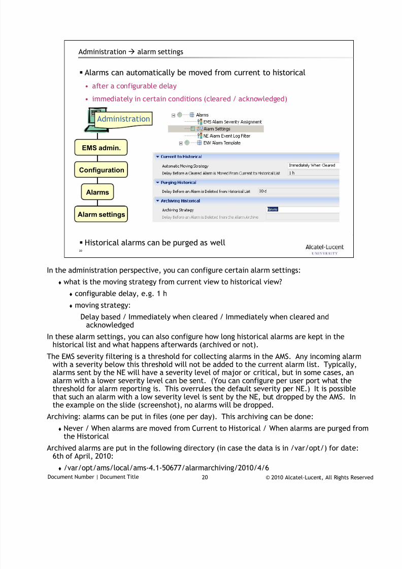
7/18/2019 Alu - A7302 Isam Fttu Operator Gpon Nant-e_ce-PDF
http://slidepdf.com/reader/full/alu-a7302-isam-fttu-operator-gpon-nant-ece-pdf 423/432
© 2010 Alcatel-Lucent, All Rights ReservedDocument Number | Document Title 20
20
Administration alarm settings
Alarms can automatically be moved from current to historical
• after a configurable delay
• immediately in certain conditions (cleared / acknowledged)
Historical alarms can be purged as well
EMS admin.
Administration
Configuration
Alarms
Alarm settings
In the administration perspective, you can configure certain alarm settings:
what is the moving strategy from current view to historical view?
configurable delay, e.g. 1 h
moving strategy:
Delay based / Immediately when cleared / Immediately when cleared andacknowledged
In these alarm settings, you can also configure how long historical alarms are kept in thehistorical list and what happens afterwards (archived or not).
The EMS severity filtering is a threshold for collecting alarms in the AMS. Any incoming alarmwith a severity below this threshold will not be added to the current alarm list. Typically,alarms sent by the NE will have a severity level of major or critical, but in some cases, analarm with a lower severity level can be sent. (You can configure per user port what thethreshold for alarm reporting is. This overrules the default severity per NE.) It is possiblethat such an alarm with a low severity level is sent by the NE, but dropped by the AMS. Inthe example on the slide (screenshot), no alarms will be dropped.
Archiving: alarms can be put in files (one per day). This archiving can be done:
Never / When alarms are moved from Current to Historical / When alarms are purged fromthe Historical
Archived alarms are put in the following directory (in case the data is in /var/opt/) for date:6th of April, 2010:
/var/opt/ams/local/ams-4.1-50677/alarmarchiving/2010/4/6
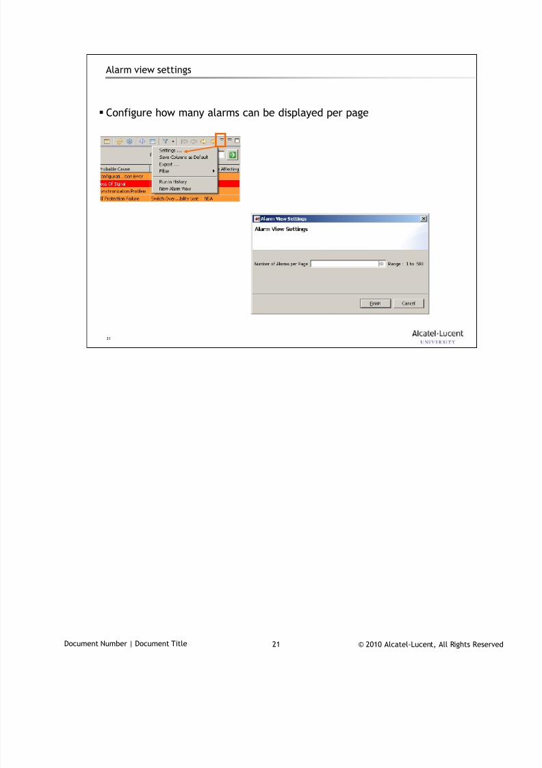
7/18/2019 Alu - A7302 Isam Fttu Operator Gpon Nant-e_ce-PDF
http://slidepdf.com/reader/full/alu-a7302-isam-fttu-operator-gpon-nant-ece-pdf 424/432
© 2010 Alcatel-Lucent, All Rights ReservedDocument Number | Document Title 21
21
Alarm view settings
Configure how many alarms can be displayed per page
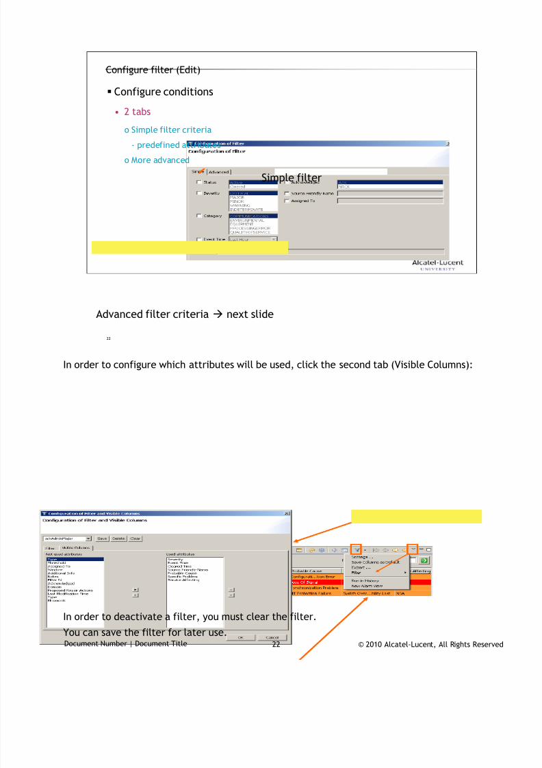
7/18/2019 Alu - A7302 Isam Fttu Operator Gpon Nant-e_ce-PDF
http://slidepdf.com/reader/full/alu-a7302-isam-fttu-operator-gpon-nant-ece-pdf 425/432
© 2010 Alcatel-Lucent, All Rights ReservedDocument Number | Document Title 22
22
Configure filter (Edit)
Configure conditions
• 2 tabs
o Simple filter criteria
- predefined attributes
o More advanced
Advanced filter criteria next slide
Simple filter
In order to configure which attributes will be used, click the second tab (Visible Columns):
In order to deactivate a filter, you must clear the filter.
You can save the filter for later use.
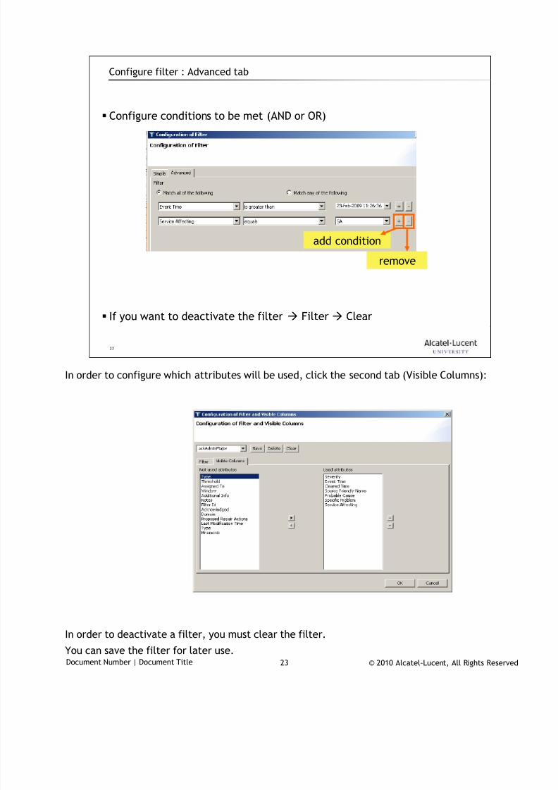
7/18/2019 Alu - A7302 Isam Fttu Operator Gpon Nant-e_ce-PDF
http://slidepdf.com/reader/full/alu-a7302-isam-fttu-operator-gpon-nant-ece-pdf 426/432
© 2010 Alcatel-Lucent, All Rights ReservedDocument Number | Document Title 23
23
Configure filter : Advanced tab
Configure conditions to be met (AND or OR)
If you want to deactivate the filter Filter Clear
add condition
remove
In order to configure which attributes will be used, click the second tab (Visible Columns):
In order to deactivate a filter, you must clear the filter.
You can save the filter for later use.
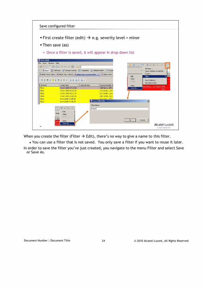
7/18/2019 Alu - A7302 Isam Fttu Operator Gpon Nant-e_ce-PDF
http://slidepdf.com/reader/full/alu-a7302-isam-fttu-operator-gpon-nant-ece-pdf 427/432
© 2010 Alcatel-Lucent, All Rights ReservedDocument Number | Document Title 24
24
Save configured filter
First create filter (edit) e.g. severity level = minor
Then save (as)• Once a filter is saved, it will appear in drop down list
When you create the filter (Filter Edit), there’s no way to give a name to this filter.
You can use a filter that is not saved. You only save a filter if you want to reuse it later.
In order to save the filter you’ve just created, you navigate to the menu Filter and select Saveor Save As.
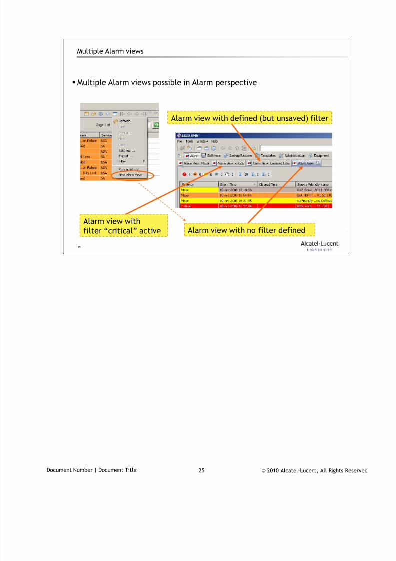
7/18/2019 Alu - A7302 Isam Fttu Operator Gpon Nant-e_ce-PDF
http://slidepdf.com/reader/full/alu-a7302-isam-fttu-operator-gpon-nant-ece-pdf 428/432
© 2010 Alcatel-Lucent, All Rights ReservedDocument Number | Document Title 25
25
Multiple Alarm views
Multiple Alarm views possible in Alarm perspective
Alarm view with no filter definedAlarm view with
filter “critical” active
Alarm view with defined (but unsaved) filter
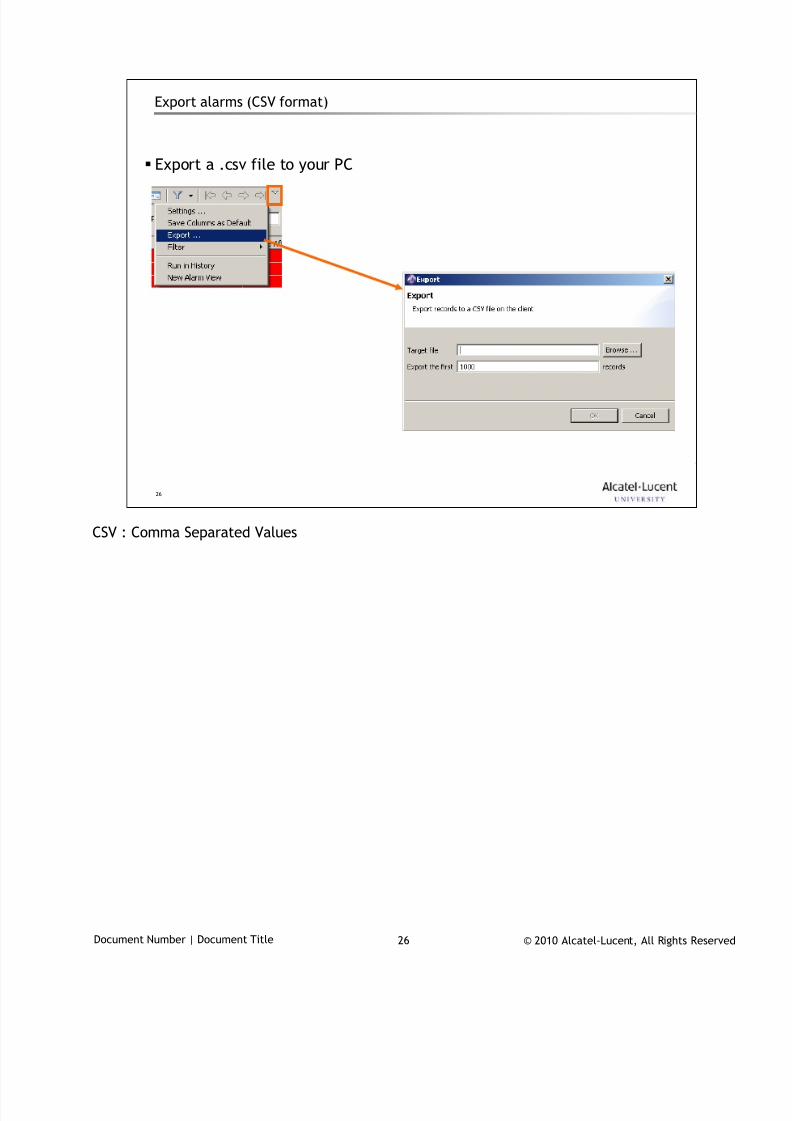
7/18/2019 Alu - A7302 Isam Fttu Operator Gpon Nant-e_ce-PDF
http://slidepdf.com/reader/full/alu-a7302-isam-fttu-operator-gpon-nant-ece-pdf 429/432
© 2010 Alcatel-Lucent, All Rights ReservedDocument Number | Document Title 26
26
Export alarms (CSV format)
Export a .csv file to your PC
CSV : Comma Separated Values
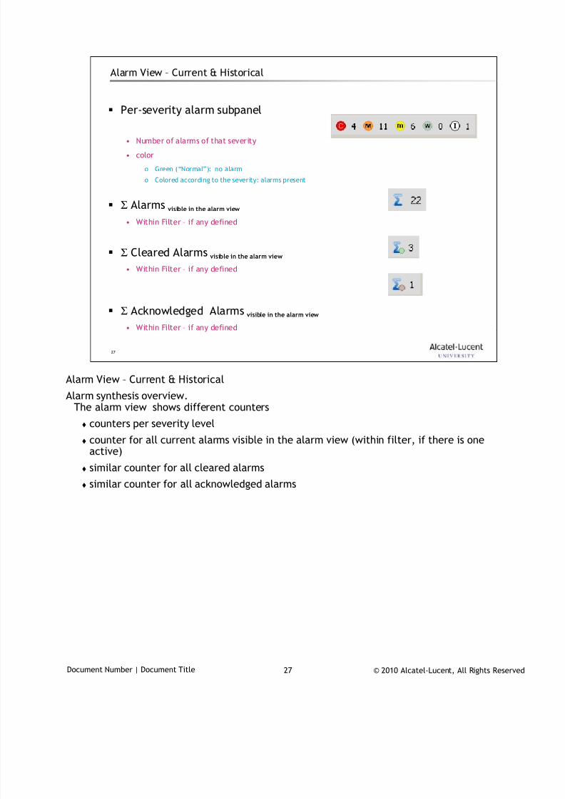
7/18/2019 Alu - A7302 Isam Fttu Operator Gpon Nant-e_ce-PDF
http://slidepdf.com/reader/full/alu-a7302-isam-fttu-operator-gpon-nant-ece-pdf 430/432
© 2010 Alcatel-Lucent, All Rights ReservedDocument Number | Document Title 27
27
Alarm View – Current & Historical
Per-severity alarm subpanel
• Number of alarms of that severity
• color
o Green (“Normal”): no alarm
o Colored according to the severity: alarms present
Σ Alarms visible in the alarm view
• Within Filter – if any defined
Σ Cleared Alarmsvisible in the alarm view
• Within Filter – if any defined
Σ Acknowledged Alarms visible in the alarm view
• Within Filter – if any defined
Alarm View – Current & Historical
Alarm synthesis overview.The alarm view shows different counters
counters per severity level
counter for all current alarms visible in the alarm view (within filter, if there is oneactive)
similar counter for all cleared alarms
similar counter for all acknowledged alarms
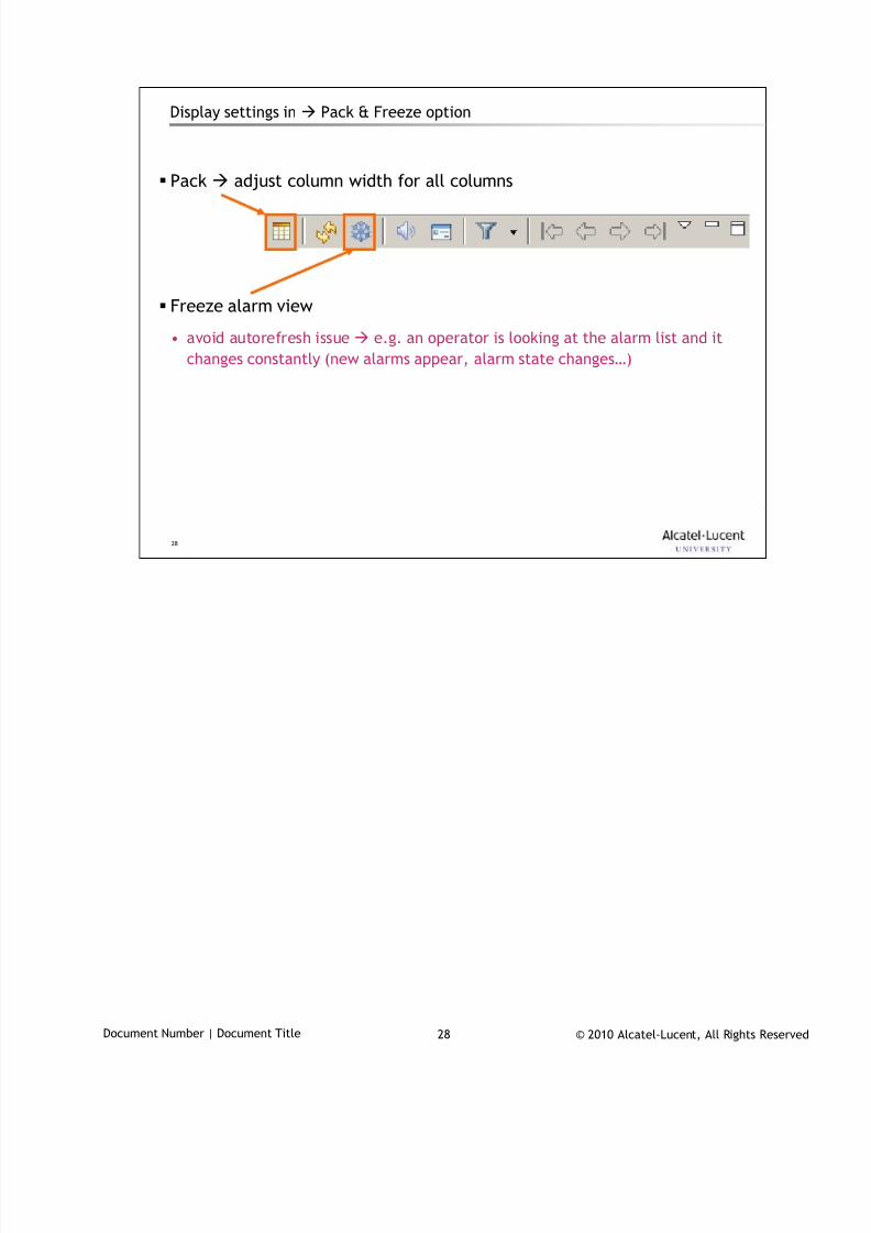
7/18/2019 Alu - A7302 Isam Fttu Operator Gpon Nant-e_ce-PDF
http://slidepdf.com/reader/full/alu-a7302-isam-fttu-operator-gpon-nant-ece-pdf 431/432
© 2010 Alcatel-Lucent, All Rights ReservedDocument Number | Document Title 28
28
Display settings in Pack & Freeze option
Pack adjust column width for all columns
Freeze alarm view
• avoid autorefresh issue e.g. an operator is looking at the alarm list and it
changes constantly (new alarms appear, alarm state changes…)
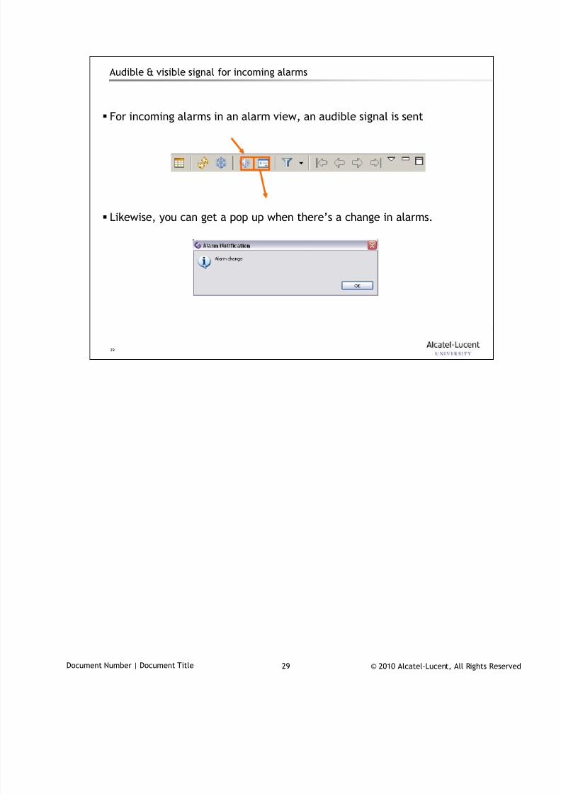
7/18/2019 Alu - A7302 Isam Fttu Operator Gpon Nant-e_ce-PDF
http://slidepdf.com/reader/full/alu-a7302-isam-fttu-operator-gpon-nant-ece-pdf 432/432
29
Audible & visible signal for incoming alarms
For incoming alarms in an alarm view, an audible signal is sent
Likewise, you can get a pop up when there’s a change in alarms.