aluminium banding and special assemblies - almet · pdf filealuminium bonding and special...
TRANSCRIPT
115
Alcan
Mari
ne
1. Screw and bolt fastenings . . . . . . . . . . . . . . . . . . . . . . . . . . . . . . . . . . . . . . . . . . . . . . . . . . . . . . 1161.1 Conventional screw fastenings . . . . . . . . . . . . . . . . . . . . . . . . . . . . . . . . . . . . . . . . . . . . . . . . . . . . . . . 1171.2 Thread inserts . . . . . . . . . . . . . . . . . . . . . . . . . . . . . . . . . . . . . . . . . . . . . . . . . . . . . . . . . . . . . . . . . . . . 118
2. Machine rivets . . . . . . . . . . . . . . . . . . . . . . . . . . . . . . . . . . . . . . . . . . . . . . . . . . . . . . . . . . . . . . . . . 1182.1 Clinch studs . . . . . . . . . . . . . . . . . . . . . . . . . . . . . . . . . . . . . . . . . . . . . . . . . . . . . . . . . . . . . . . . . . . . . 1192.2 Blind rivets . . . . . . . . . . . . . . . . . . . . . . . . . . . . . . . . . . . . . . . . . . . . . . . . . . . . . . . . . . . . . . . . . . . . . . 1192.3 Threaded inserts . . . . . . . . . . . . . . . . . . . . . . . . . . . . . . . . . . . . . . . . . . . . . . . . . . . . . . . . . . . . . . . . . . 1192.4 Repetition fasteners . . . . . . . . . . . . . . . . . . . . . . . . . . . . . . . . . . . . . . . . . . . . . . . . . . . . . . . . . . . . . . . 1212.5 Self-piercing rivets . . . . . . . . . . . . . . . . . . . . . . . . . . . . . . . . . . . . . . . . . . . . . . . . . . . . . . . . . . . . . . . . 1212.6 Rivet selection criteria . . . . . . . . . . . . . . . . . . . . . . . . . . . . . . . . . . . . . . . . . . . . . . . . . . . . . . . . . . . . . 1212.7 Important note . . . . . . . . . . . . . . . . . . . . . . . . . . . . . . . . . . . . . . . . . . . . . . . . . . . . . . . . . . . . . . . . . . . 121
3. Bonding . . . . . . . . . . . . . . . . . . . . . . . . . . . . . . . . . . . . . . . . . . . . . . . . . . . . . . . . . . . . . . . . . . . . . . 1223.1 Advantages of bonding . . . . . . . . . . . . . . . . . . . . . . . . . . . . . . . . . . . . . . . . . . . . . . . . . . . . . . . . . . . . 1223.2 Designing a bonded joint . . . . . . . . . . . . . . . . . . . . . . . . . . . . . . . . . . . . . . . . . . . . . . . . . . . . . . . . . . . 1223.3 Choice of adhesive . . . . . . . . . . . . . . . . . . . . . . . . . . . . . . . . . . . . . . . . . . . . . . . . . . . . . . . . . . . . . . . 1233.4 Surface preparation . . . . . . . . . . . . . . . . . . . . . . . . . . . . . . . . . . . . . . . . . . . . . . . . . . . . . . . . . . . . . . . 1243.5 Industrial fabrication . . . . . . . . . . . . . . . . . . . . . . . . . . . . . . . . . . . . . . . . . . . . . . . . . . . . . . . . . . . . . . . 1243.6 Repair of bonded joints . . . . . . . . . . . . . . . . . . . . . . . . . . . . . . . . . . . . . . . . . . . . . . . . . . . . . . . . . . . . 1243.7 Durability of bonded joints . . . . . . . . . . . . . . . . . . . . . . . . . . . . . . . . . . . . . . . . . . . . . . . . . . . . . . . . . . 1243.8 Note . . . . . . . . . . . . . . . . . . . . . . . . . . . . . . . . . . . . . . . . . . . . . . . . . . . . . . . . . . . . . . . . . . . . . . . . . . 125
4. Transition joints . . . . . . . . . . . . . . . . . . . . . . . . . . . . . . . . . . . . . . . . . . . . . . . . . . . . . . . . . . . . . . . 1264.1 Parts of a transition joint . . . . . . . . . . . . . . . . . . . . . . . . . . . . . . . . . . . . . . . . . . . . . . . . . . . . . . . . . . . 1264.2 Properties of transition joints . . . . . . . . . . . . . . . . . . . . . . . . . . . . . . . . . . . . . . . . . . . . . . . . . . . . . . . . 1264.3 Conditions of use . . . . . . . . . . . . . . . . . . . . . . . . . . . . . . . . . . . . . . . . . . . . . . . . . . . . . . . . . . . . . . . . . 126
C h a p t e r 7A L U M I N I U M B O N D I N G A N D S P E C I A L A S S E M B L I E S
115

ARC WELDING is the method offabrication most com-
monly used in aluminium sheetmetal working in general and inshipbuilding in particular.
However there are other methodsof joining which complement arcwelding, such as screw and boltfastenings, riveting and adhesivebonding. Since these methods donot require any application of heat,they have the advantage overwelding of not affecting themechanical properties of the metalor introducing distortion.
They are essential when differentmaterials have to be joinedtogether, e.g. steel to aluminium(or vice versa) or polymers (or their
composites) to aluminium. These‘mixed’ joints are found in most ofthe internal equipment of a shipsuch as the propulsion system,auxiliaries, pipework, ceilings,door and window frames etc.Since the early Seventies, thewelding of aluminium alloy struc-tures to steel structures has beenmade easier by the use of alu-minium/steel transition joints. Oneof the most common instances isthat of a ship with a superstructuremade of aluminium alloy and asteel hull.This chapter deals with:■ screw and bolt fastenings,■ riveting: machine rivets,■ adhesive bonding,■ transition joint.
1.SCREW AND BOLTFASTENINGS
Unlike welding, bolting creates ajoint that can be ‘undone’ and isused extensively to make mixedjoints, e.g. steel/aluminium. Thistype of joint is therefore very com-mon in connections between thestructure of a ship and much of itsequipment, such as engines, auxil-iaries, pipework and ventilationducts.
116
Alcan
Mari
ne
7 . A L U M I N I U M B O N D I N G
116
FELICITA WEST

117
Alcan
Mari
ne
1.1Conventional screwfastenings
The choice of fastening will dependon mechanical considerations fol-lowing a calculation of the load onthe joint. Given the marine environ-ment, increasing use is made ofstainless steel fastenings that havethe advantage of not rusting and sopreserve their original appearance.
When the joint is subjected toextreme variations of temperature,it will be necessary to fit washersto absorb the different rates ofexpansion between steels and alu-minium alloys.
Allowance must also be made forthe risk of bimetallic corrosion ofthe aluminium in contact with thefastenings if they are made frommild, galvanised or stainless steel.
Bearing in mind what is said aboutgalvanic corrosion in Chapter 10,two cases in point must be con-sidered:
■ the joint is submerged (whetherpermanently or intermittently) insea water. Here, we cannot usescrew fastenings made from mildor stainless steel without protec-ting the contacts: - by placing insulation between thescrew and the aluminium struc-ture (figure 100),- by cathodic protection if they arebelow the waterline (1).
This risk of galvanic corrosion canalso be avoided by using alu-minium alloy screws which areanodised to a depth of 15 micronsand sealed with bichromate in
7075 T73 or 6108 T8 – theirmechanical properties are shownbelow in table 58, p. 118.Aluminium alloy screws are 50 %lighter than steel screws of equaldiameter.
■ the joint is out of water: in zonesthat are at worst damp as opposedto actually wet, frequent use ismade of screw fastenings in stain-less steel or galvanised steel.
A N D S P E C I A L A S S E M B L I E S
117
PROTECTION OF BOLTED JOINTS
Dry atmosphere Marine atmosphereFrom TALAT de EAA
Steel
Stainless steelSteel
Aluminium Aluminium
Stainless steelWatertight sealStainless steel
Watertight seal Aluminium
Figure 100
(1) Cf. Chapter 11.
Steel
FELICITA WEST

Despite the difference in potentialbetween steels and aluminiumalloys, there is virtually no risk ofbimetallic corrosion to aluminiumor its alloys aside from a verysuperficial attack limited to thecontact area.
Experience shows that screwsmade from mild (or stainless) steelthat have been screwed into alu-minium are often difficult and evenimpossible to remove when mois-ture has been allowed to pene-trate the thread. This is because ofthe bimetallic corrosion of the alu-minium which, though very super-ficial, is enough for alumina toform and seize the steel screw.
The simplest way of avoiding thisis to apply a viscous grease to thehole and the screw to create ahydrophobic environment that willprevent the ingress of moisture.
1.2Thread inserts
Experience shows that threads inaluminium do not stand up well tofrequent dismantling, and here theanswer is to fit thread insertsmade of steel into the aluminiumalloy component (figure 101).Here again, moisture must not beallowed to penetrate the threadand have the adverse effectsdescribed above.
2.MACHINE RIVETS
Originally developed for aerospaceapplications, machine riveting isnow in widespread use in manysectors of industry, including elec-tronics, domestic appliances andvehicles.
In shipbuilding, this method ofjoining is used for fixing pipe sup-ports, suspended ceilings, interiortrim (salsons, lobbies etc.) and fur-niture.
Manufacturers of this type of rivetare now offering very reliable sys-tems suitable for use in a widevariety of applications, andmachine riveting does not requireskilled operatives.
Machine riveting has a number ofdecisive advantages:
■ Rapid fitting: Machine rivetingcan be very fast with the use ofpneumatic or hydraulic tools. Theactual rate of riveting will of coursedepend on the nature and configu-ration of the joints.■ Ease of control: Controlling thequality of a joint is made easier bythe fact that the clamping force isalways guaranteed and optimumbecause it is less than the forceneeded to snap the rivet stem. ■ Appearance and impermeability:With some types of rivet a plasticcap can be clipped over the rivethead to enhance the appearanceof the joint. This also helps to
improve the structure’s impermea-bility to air, dust and splash water.■ Mixed joints are possible: alumi-nium/steel, aluminium/polymer,aluminium/composite etc.
There are two families of machinerivets:■ clinch studs (or structural rivets)create the same type of connec-tion as a conventional bolt,although they cannot be undone.Clinch bolts require both sides ofthe joint to be accessible,
■ blind rivets are used when onlyone side of the joint is accessible.They too create a permanent fas-tening and cannot be undone.
The components are gripped:■ either by clinching a ring ontothe stem of the rivet to preload it,■ or by upsetting the body of therivet by means of the stem headto form a “counter head” on theside opposite the rivet entry.
These operations are carried outwith manual riveting tool or withpneumatic or hydraulic rivet gunswhich are usually sold by the rivetmanufacturers.
These fastenings cannot beundone, which ensures the safetyof the joint but also complicatesrepair work. However repairs arerarely needed thanks to themechanical performance of theserivets. This type of connection isalso chosen for its permanenceand ‘finality’.
118
Alcan
Mari
ne
118
MECHANICAL PROPERTIES OF ALUMINIUM ALLOY SCREWS
Alloy Rm (MPa) Rp0,2 (MPa) A % 6108 T6 300 260 8 7075 T73 550 470 10 Steel E24 410 240 24Stainless steel 660 300 54
Table 58
THREAD INSERTS
From TALAT de l’EAA
Ensat thread insert, having bothinternal and external threads
Heli-coil thread insert,consisting of a wire ofrhombic cross-section coiled into a helical spring
Figure 101
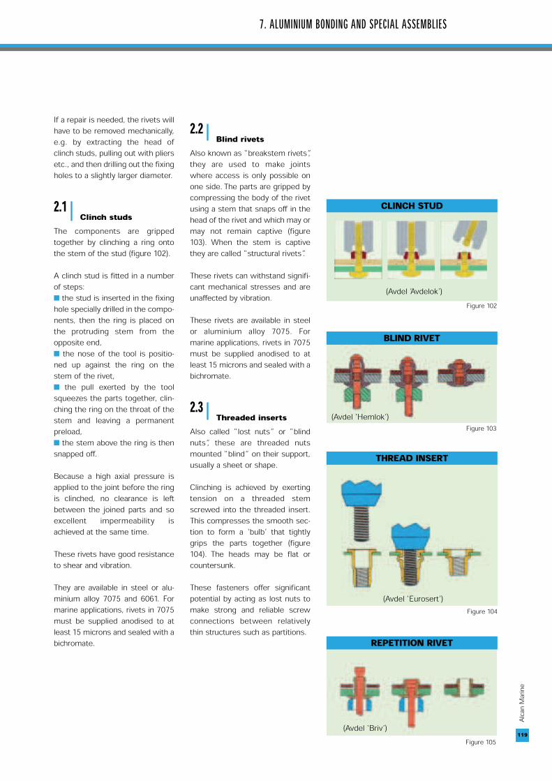
If a repair is needed, the rivets willhave to be removed mechanically,e.g. by extracting the head ofclinch studs, pulling out with pliersetc., and then drilling out the fixingholes to a slightly larger diameter.
2.1Clinch studs
The components are grippedtogether by clinching a ring ontothe stem of the stud (figure 102).
A clinch stud is fitted in a numberof steps: ■ the stud is inserted in the fixinghole specially drilled in the compo-nents, then the ring is placed onthe protruding stem from theopposite end,■ the nose of the tool is positio-ned up against the ring on thestem of the rivet,■ the pull exerted by the toolsqueezes the parts together, clin-ching the ring on the throat of thestem and leaving a permanentpreload,■ the stem above the ring is thensnapped off.
Because a high axial pressure isapplied to the joint before the ringis clinched, no clearance is leftbetween the joined parts and soexcellent impermeability isachieved at the same time.
These rivets have good resistanceto shear and vibration.
They are available in steel or alu-minium alloy 7075 and 6061. Formarine applications, rivets in 7075must be supplied anodised to atleast 15 microns and sealed with abichromate.
2.2Blind rivets
Also known as “breakstem rivets”,they are used to make jointswhere access is only possible onone side. The parts are gripped bycompressing the body of the rivetusing a stem that snaps off in thehead of the rivet and which may ormay not remain captive (figure103). When the stem is captivethey are called “structural rivets”.
These rivets can withstand signifi-cant mechanical stresses and areunaffected by vibration.
These rivets are available in steelor aluminium alloy 7075. Formarine applications, rivets in 7075must be supplied anodised to atleast 15 microns and sealed with abichromate.
2.3Threaded inserts
Also called “lost nuts” or “blindnuts”, these are threaded nutsmounted “blind” on their support,usually a sheet or shape.
Clinching is achieved by exertingtension on a threaded stemscrewed into the threaded insert.This compresses the smooth sec-tion to form a ‘bulb’ that tightlygrips the parts together (figure104). The heads may be flat orcountersunk.
These fasteners offer significantpotential by acting as lost nuts tomake strong and reliable screwconnections between relativelythin structures such as partitions.
7. ALUMINIUM BONDING AND SPECIAL ASSEMBLIES
119
Alcan
Mari
ne
119
CLINCH STUD
(Avdel ’Avdelok’)Figure 102
BLIND RIVET
(Avdel ‘Hemlok’)Figure 103
THREAD INSERT
(Avdel ‘Eurosert’)Figure 104
REPETITION RIVET
(Avdel ‘Briv’)Figure 105
120
Alcan
Mari
ne
120
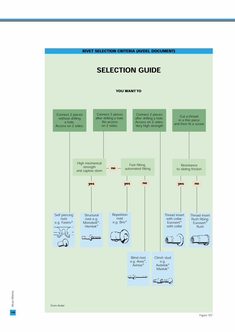
SELECTION GUIDE
YOU WANT TO
Connect 2 piecesafter drilling a hole.
No access on 2 sides.
Connect 2 piecesafter drilling a hole.Access on 2 sides.Very high strength
Cut a thread in a thin piece
and then fit a screw
RIVET SELECTION CRITERIA (AVDEL DOCUMENT)
no
Structuralrivet e.g.
Monobolt®,Hemlok®
Self piercingrivet
e.g. Fastriv®
Repetitionrivet
e.g. Briv®
Blind rivete.g. Avex®,
Avinox®
Clinch stude.g.
Avdelok®Maxlok®
Thread insert with collar:Eurosert®with collar
Thread insert flush fitting:Eurosert®
flush
noyesnoyesyes
Resistance to sliding friction
Fast fitting, automated fitting
High mechanicalstrength
and captive stem
Connect 2 pieceswithout drilling
a hole.Access on 2 sides.
From Avdel
Figure 107

2.4Repetition fasteners
So called because they are fixedblind (by radial expansion of thestem) with a re-usable punch towhich the rivets are fed from aloader (figure 105, p. 119).
These rivets have moderatemechanical strength and are onlyused for joints under light loads.They can be placed by continu-ously fed automatic riveters.
2.5Self-piercing rivets
This is a hybrid technique thatcombines riveting and clinching,and requires access on both sidesof the joint (figure 106).
It can be automated. The compo-nents to be joined together are notpre-drilled, and a tight seal is guar-anteed as the rivet does not piercethe final layer of material.
2.6Rivet selectioncriteria
The choice of rivet type dependson a number of criteria (figure107):■ accessibility on 1 or 2 sides,■ prior drilling,■ intensity of stress on the joint,etc.
2.7Important note
When using machine rivets madeof mild or stainless steel it isessential to protect the contactzone if this will be permanently orintermittently submerged in (sea)water. The risk of bimetallic corrosion ofthe aluminium can be preventedby applying a sealing compound tothe contact areas between theplates and to the rivets to preventingress of water along the stem.
Sealing compounds must satisfy anumber of requirements:■ they must be inert to aluminiumalloys,■ the coating must be as thin aspossible to minimise the adverseeffect of the joint on the strengthof the structure,■ they must have good “squeeza-bility” around the stem of the rivetto permit close contact betweenthe plates.
7. ALUMINIUM BONDING AND SPECIAL ASSEMBLIES
121
Alcan
Mari
ne
121
SELF-PIERCING RIVET
1) The tool holds the pieces betweenthe punch and the die.2) The FastRiv pierces the first pieceand expands radially (3) in the secondpiece but without piercing it.
(Avdel ‘FastRiv’)Figure 106
HYDROJET NOZZLE

122
Alcan
Mari
ne
3.BONDING
Industrial bonding has undergonesignificant development since1960, initially in aerospace applica-tions with honeycomb structures.In automotive, the bonding ofwindscreens to car bodies beganin 1963 and has since spread to alltypes of motor vehicles. Today, allthe major industries – automotive,domestic appliances, office equip-ment, electronics etc. – use adhe-sive bonding as an assemblymethod [1].
In marine construction, the usesof structural bonding are still lim-ited and concern mainly hybridjoints of aluminium with glass andcomposites [2].The windows ofhigh speed ships built in Australiafor example are bonded, the effectof which is to increase the rigidityof aluminium alloy superstructures[3]. The bonding of floors made ofaluminium tread plate in theengine room simplifies installationand reduces the transmission ofvibrations (Sika brochure photo,page 4-16).
Bonding is used more widely inyacht building, e.g. to attach teakplanking to the roof of the deck-house, whether made of polymeror aluminium, to mount certainitems of deck equipment (chainplates, winches, capstans etc.).
Ongoing technological research isaimed at significantly increasingthe part played by bonding in ship-building, especially in homoge-nous aluminium/aluminium jointsand mixed aluminium/steel andaluminium/composite joints [4].
3.1Advantages of bonding
The use of bonding in shipbuildingis set to grow given the advan-tages it offers, particularly its abil-ity to simplify assembly.
Compared with other joining tech-niques, bonding can be used to: ■ connect materials of differenttypes: aluminium to steel, alumi-nium to composites etc. Becauseadhesives also insulate, they pre-vent the bimetallic corrosion ofaluminium in contact with theother materials in the joint,■ compensate differences ofexpansion in a mixed joint bet-ween different materials,■ join age hardening aluminiumalloys in the 2000 and 7000 seriesthat cannot be arc welded (2),■ enhance stress distribution(continuous joint),■ absorb vibrations, the more sothe thicker the joint,■ ensure built-in impermeability,■ join sub-assemblies that are inan advanced state of completion(painting, various decorations etc.)– this would be impossible withwelding as the heat woulddamage the finishes, ■ increase the tolerance of bon-ded joints compared with otherjointing methods.
The use of bonding instead ofwelding avoids heating and there-fore eliminates the heat affectedzone, thus bonding preserves theinitial mechanical properties of alu-minium.
This has two important implica-tions:■ the thickness of componentscan be reduced to further saveweight in bonded sub-assemblies,■ it eliminates distortion and sosaves time.
3.2Designinga bonded joint
The success of a bonded jointdepends on a number of factors:■ a knowledge of the serviceconditions of the joints (in particu-lar, specifications must indicatethe environment),■ engineers must think ‘bonding’from the design stage,■ careful surface preparation,■ correct choice of adhesive – itmust suit the service conditions,■ testing to destruction beforefabrication to validate the choice ofadhesive, and also during fabrica-tion if NDT testing is not possiblefor reasons of cost, for example,■ fabrication should be closelycontrolled and automated as far aspossible.
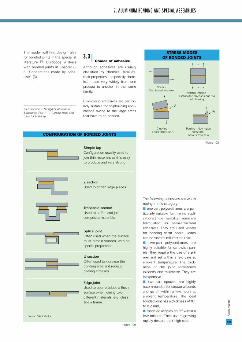
There are four types of stress towhich a bonded joint can beexposed (figure 108): ■ shear, ■ tension,■ cleaving and■ peeling.Bonded joints do not resist well topeeling or cleaving, so should bedesigned to work in shear and ten-sion.
Joints should be adequatelylapped (flat geometry) or sleeved,and the influence of the materialsand the thickness of the adhesivelayer must also be taken intoaccount.
To compensate for the relativelypoor mechanical properties of thebonded joint, the joint’s areasshould be as large as possible in theusual configurations (figure 109).122
(2) Provided of course they are specially protected for use in marineenvironments. Stoving the adhesive (forseveral minutes at temperatures below200°C) does not affect their mechanicalproperties.
7. ALUMINIUM BONDING AND SPECIAL ASSEMBLIES
123
Alcan
Mari
ne
The reader will find design rulesfor bonded joints in the specialistliterature [5]. Eurocode 9 dealswith bonded joints in Chapter 6-8 “Connections made by adhe-sive“ (3).
3.3Choice of adhesive
Although adhesives are usuallyclassified by chemical families,their properties – especially chem-ical – can vary widely from oneproduct to another in the samefamily.
Cold-curing adhesives are particu-larly suitable for shipbuilding appli-cations owing to the large areasthat have to be bonded.
The following adhesives are worthnoting in this category:■ one-part polyurethanes are par-ticularly suitable for marine appli-cations (impermeability); some areformulated as semi-structuraladhesives. They are used widelyfor bonding yacht decks. Jointscan be several millimetres thick,■ two-part polyurethanes arehighly suitable for sandwich pan-els. They require the use of a pri-mer and set within a few days atambient temperature. The thick-ness of the joint sometimesexceeds one millimetre. They areinexpensive.■ two-part epoxies are highlyrecommended for structural bondsand go off within a few hours atambient temperature. The idealbonded joint has a thickness of 0.1to 0.2 mm,■ modified acrylics go off within afew minutes. Their use is growingrapidly despite their high cost. 123
STRESS MODES OF BONDED JOINTS
➤
➤
➤ ➤ ➤
➤ ➤ ➤
➤
➤
➤
➤
➤
Shear - Distributed stresses Normal tension -
Distributed stresses but risk of cleaving
Cleaving - Local stress at A
Peeling - Non rigide substrate -
Local stress at A
AA
Simple lapConfiguration usually used tojoin thin materials as it is easyto produce and very strong.
Z section Used to stiffen large pieces.
Trapezoïd sectionUsed to stiffen and joincomposite materials.
Splice joint Often used when the surfacemust remain smooth, with nospecial preparation.
U section Often used to increase thebonding area and reducepeeling stresses.
Edge jointUsed to pour produce a flushsurface when joining twodifferent materials, e.g. glassand a frame.
CONFIGURATION OF BONDED JOINTS
Source: Sika Industry
Figure 109
Figure 108
(3) Eurocode 9. Design of AluminiumStructures. Part 1 – 1 General rules andrules for buildings.

Other types of adhesives may alsobe used, e.g.:■ anaerobic adhesives for threadlocking,■ one-part silicone for resolvingproblems of water tightness,■ one-part epoxies for joints sub-ject to high stress levels and likelyto be stoved.
Each of these families includesadhesives specially designed formarine environments.
3.4Surface preparation
Good surface preparation is vital toensure the quality and long life ofthe bonded joint [6].
Two typical procedures for interiorbonds are given below:
■ First procedure:– chemical degreasing, either alka-line or acid (preferred), or usingnon chlorinated organic solventslike Evopred made by SID (4),– chemical conversion – phospho-ric or without chromates,– apply a primer, e.g. an epoxy.■ Second procedure:– degrease (as above),– apply a wash primer.
Bonding should be carried out assoon as possible after surfacepreparation, but the interval can beas long as several days providedthe components are stored in aclean, dry room.
There are also pre-coated sheetsin which the front face is paintedand the back is ready coated witha special epoxy bonding primer.These sheets are ideal for the fab-rication of sandwich panels.
3.5Industrial fabrication
As far as possible bonding shouldbe done in a well ventilated anddust-free workshop.
It is essential to work carefully andmethodically:■ wearing white gloves and safetyglasses,■ in strict compliance with theadhesive manufacturer’s direc-tions, including storage instruc-tions, e.g. time and temperature.
At each stage of production theremust be proper controls of param-eters such as resin/hardenerratios, duration and pressure ofcomponent fitup during adhesivecuring, curing temperature etc.
Standard specimens should betested to destruction (5) with:■ tension/shear tests with accele-rated ‘wet pad’ ageing, ■ or peel tests, to monitor any anomalies.
3.6Repair of bondedjoints
When structures are required tolast for several decades, therecomes a time when they mayhave to be repaired because ofdamage or for a modification.
Joints made with rigid adhesivesapplied as a film are very difficultto dismantle. Joints made withflexible adhesives are easy torepair or replace provided they areat least 2 millimetres thick.
Under these conditions the jointcan be easily dismantled using ametal wire or vibrating knife andwithout damaging the substrate.
It is not always necessary toremove the traces of the old adhe-sive. When treated with a suitable“activator” (which improves the
adhesion of the substrate), theycan form an excellent substrate forfresh adhesive of the same type.
3.7Durabilityof bonded joints
The durability of bonded jointsdepends on factors such as: ■ the chemical composition of theadhesives,■ the surface treatment of the alu-minium,■ service conditions: stresses,temperature, humidity etc.
The ageing of bonded joints maybe accompanied by:■ a loss of mechanical properties,■ creep under stress.
The loss of mechanical propertiesis due either to the transformationof the surface of the metal (a mod-ification of the oxide layer) or tochanges in the properties of theadhesive (softening, hydrolysisetc.).
Water does most damage tobonded joints by attacking theadhesive or causing surface corro-sion of the metal (6).
Adhesive bonding has been usedin shipbuilding for over 15 yearsnow but our knowledge of theageing process of bonded joints isstill fragmentary.
Over 12 years of experience withmarine environments indicatesthat the two-part epoxies displayvery good strength provided thejoints are well designed and theirsurfaces are properly prepared.
124
Alcan
Mari
ne
124
(4) SID: Société Industrielle de DiffusionF38140 IZEAUX.(5) According to standard EN 1465“Adhesives - Determination of tensilelap-shear strength of rigid-to-rigidbonded assemblies”.(6) Which accounts for the importance ofsurface treating aluminium to reinforcethe properties of the natural oxide film.
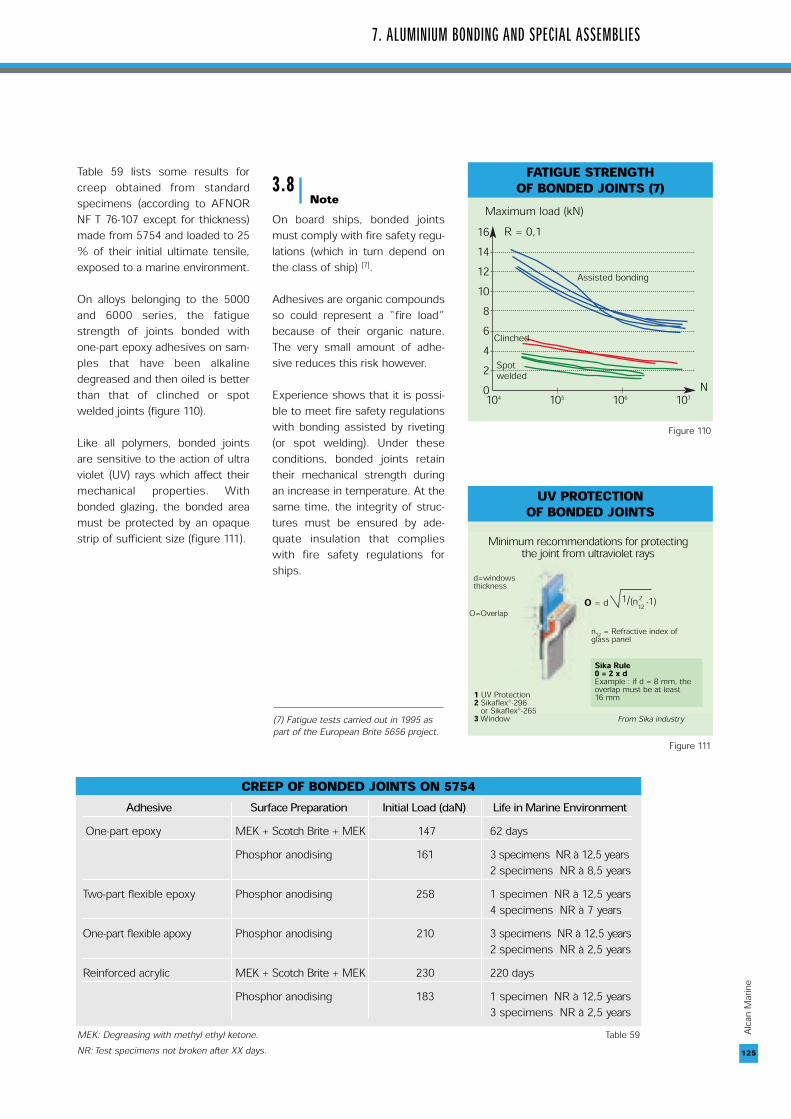
Table 59 lists some results forcreep obtained from standardspecimens (according to AFNORNF T 76-107 except for thickness)made from 5754 and loaded to 25% of their initial ultimate tensile,exposed to a marine environment.
On alloys belonging to the 5000and 6000 series, the fatiguestrength of joints bonded withone-part epoxy adhesives on sam-ples that have been alkalinedegreased and then oiled is betterthan that of clinched or spotwelded joints (figure 110).
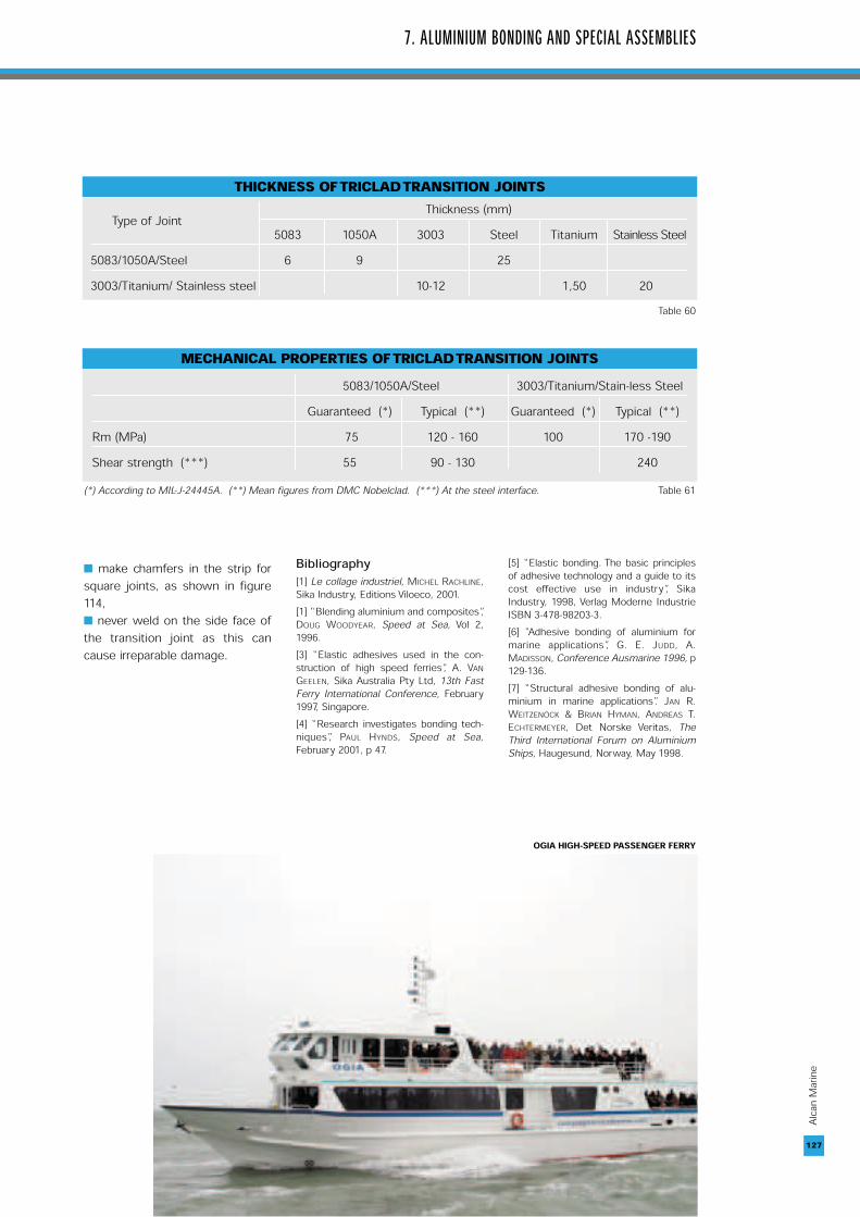
Like all polymers, bonded jointsare sensitive to the action of ultraviolet (UV) rays which affect theirmechanical properties. Withbonded glazing, the bonded areamust be protected by an opaquestrip of sufficient size (figure 111).
3.8Note
On board ships, bonded jointsmust comply with fire safety regu-lations (which in turn depend onthe class of ship) [7].
Adhesives are organic compoundsso could represent a “fire load”because of their organic nature.The very small amount of adhe-sive reduces this risk however.
Experience shows that it is possi-ble to meet fire safety regulationswith bonding assisted by riveting(or spot welding). Under theseconditions, bonded joints retaintheir mechanical strength duringan increase in temperature. At thesame time, the integrity of struc-tures must be ensured by ade-quate insulation that complieswith fire safety regulations forships.
7. ALUMINIUM BONDING AND SPECIAL ASSEMBLIES
125
Alcan
Mari
ne
CREEP OF BONDED JOINTS ON 5754 Adhesive Surface Preparation Initial Load (daN) Life in Marine Environment
One-part epoxy MEK + Scotch Brite + MEK 147 62 daysPhosphor anodising 161 3 specimens NR à 12,5 years
2 specimens NR à 8,5 yearsTwo-part flexible epoxy Phosphor anodising 258 1 specimen NR à 12,5 years
4 specimens NR à 7 yearsOne-part flexible apoxy Phosphor anodising 210 3 specimens NR à 12,5 years
2 specimens NR à 2,5 yearsReinforced acrylic MEK + Scotch Brite + MEK 230 220 days
Phosphor anodising 183 1 specimen NR à 12,5 years3 specimens NR à 2,5 years
MEK: Degreasing with methyl ethyl ketone. Table 59NR: Test specimens not broken after XX days.
FATIGUE STRENGTH OF BONDED JOINTS (7)
1614121086420104 105 106 107
N
Maximum load (kN)R = 0,1
Assisted bonding
Clinched
Spotwelded
UV PROTECTION OF BONDED JOINTS
From Sika industry
d=windowsthickness
O=Overlap
1 UV Protection 2 Sikaflex®-296or Sikaflex®-2653 Window
Sika Rule0 = 2 x dExample : if d = 8 mm, theoverlap must be at least16 mm
n12 = Refractive index ofglass panel
O = d 1/(n 212 -1)
Minimum recommendations for protecting the joint from ultraviolet rays
Figure 110
Figure 111
(7) Fatigue tests carried out in 1995 aspart of the European Brite 5656 project.

4.TRANSITION JOINTS
Introduced at the beginning of theSeventies, the transition joint is atwo-metal strip used to arc welddissimilar metals and alloys, espe-cially when they cannot be joinedtogether by any conventionalwelding process (8).
A transition joint suitable for con-necting aluminium and steel cantherefore be used to MIG (or TIG)weld aluminium alloy structures tosteel structures on the deck of aship or offshore platform, forexample.
4.1Parts of a transition joint
The “TRICLAD” transition jointcomprises a strip of carbon steeland a strip of aluminium. The stripof aluminium is actually 2 superim-posed layers, with a bottom layerof 1050 alloy in contact with thesteel and an upper layer in 5083alloy (figure 112). The three layers(1 steel, 2 aluminium) are joined bythe controlled explosion of anexplosive charge – explosioncladding.
Unlike the aluminium/steel hybridjoint complexes made by hot co-rolling, there are no intermetallicsin the connection zone betweenthe aluminium and the steel of theTRICLAD.
The explosion is followed by veryrapid cooling (lasting approx. 1microsecond) which prevents theformation of these intermetallicsthat would otherwise affect thequality of the joint between thealuminium and the steel. It is con-sidered that “micro-fusion” takesplace at the interface between thetwo metals over a thickness of 10to 50 microns.
4.2Properties of transition joints
The thickness of the componentsof standard transition joints, calcu-lated not to exceed 300 °C at thealuminium/steel interface (undernormal welding conditions), isgiven in table 60.
The mechanical properties of TRI-CLAD are shown in table 61. Ontest specimens taken square tothe plane of the aluminium/steeljoint, ‘necking’ always occurs inthe aluminium part beyond theconnection zone between the twometals.
4.3Conditions of use
The width of transition joints mustbe 4 times the thickness of wel-ded sheets in 5083 alloy. Standardproducts are 25 mm wide whichallows sheet up to 6 mm thick tobe welded.
A number of strict rules must befollowed when using transitionjoints to avoid irreparable damageto the connection:
■ the temperature at the interfaceof the joint must be limited to 300°C in both metals to prevent theformation of intermetallics bet-ween the aluminium and the steel.In practice, it is advisable to do atest under normal welding condi-tions while checking the tempera-ture at the interface using athermosensitive pencil or athermocouple,■ make chamfers in each of themetals for butt welds (figure 113a)but avoid crossing the interface(figure 113b) as this can damagethe joint,
126
Alcan
Mari
ne
Aluminium structure
Triclad
Steel structure
50831050ASteel
➤
➤
➤
➤
➤
From DMC Nobleclad
TRICLAD TRANSITION JOINT
Figure 112
(8) For metallurgical reasons, the fusion ofthe metals creates intermetalliccompounds that weaken the weld seam.
BUTT WELD WITH TRICLAD
➤
➤
➤
➤
➤
➤
➤
➤ 3 mm3 mm
60°
Steel ➤
Steel ➤
Aluminium ➤
Aluminium ➤
Case a
Case b
60°
SQUARE AND FILLET WELDSWITH TRICLAD
➤
➤ 3 mm
Figure 113
Figure 114
From DMC Nobleclad
From DMC Nobleclad
■ make chamfers in the strip forsquare joints, as shown in figure114,■ never weld on the side face ofthe transition joint as this cancause irreparable damage.
Bibliography[1] Le collage industriel, MICHEL RACHLINE,Sika Industry, Editions Viloeco, 2001. [1] “Blending aluminium and composites”,DOUG WOODYEAR, Speed at Sea, Vol 2,1996. [3] “Elastic adhesives used in the con-struction of high speed ferries”, A. VANGEELEN, Sika Australia Pty Ltd, 13th FastFerry International Conference, February1997, Singapore. [4] “Research investigates bonding tech-niques”, PAUL HYNDS, Speed at Sea,February 2001, p 47.
[5] “Elastic bonding. The basic principlesof adhesive technology and a guide to itscost effective use in industry”, SikaIndustry, 1998, Verlag Moderne IndustrieISBN 3-478-98203-3. [6] “Adhesive bonding of aluminium formarine applications”, G. E. JUDD, A.MADISSON, Conference Ausmarine 1996, p129-136. [7] “Structural adhesive bonding of alu-minium in marine applications”. JAN R.WEITZENÖCK & BRIAN HYMAN, ANDREAS T.ECHTERMEYER, Det Norske Veritas, TheThird International Forum on AluminiumShips, Haugesund, Norway, May 1998.
7. ALUMINIUM BONDING AND SPECIAL ASSEMBLIES
127
Alcan
Mari
ne
THICKNESS OF TRICLAD TRANSITION JOINTSType of Joint Thickness (mm)
5083 1050A 3003 Steel Titanium Stainless Steel5083/1050A/Steel 6 9 25 3003/Titanium/ Stainless steel 10-12 1,50 20
Table 60
MECHANICAL PROPERTIES OF TRICLAD TRANSITION JOINTS5083/1050A/Steel 3003/Titanium/Stain-less Steel
Guaranteed (*) Typical (**) Guaranteed (*) Typical (**) Rm (MPa) 75 120 - 160 100 170 -190 Shear strength (***) 55 90 - 130 240
(*) According to MIL-J-24445A. (**) Mean figures from DMC Nobelclad. (***) At the steel interface. Table 61
OGIA HIGH-SPEED PASSENGER FERRY

128
Alcan
Mari
ne
AUSSIE RULES