alunord week 41, 2009
TRANSCRIPT

Department for Civil Engineering, AAU, Esbjerg Campus
ALUNORDALUNORDWeek 41, 2009
CONSTRUCTION in ALUMINIUM – Part I
by Anders Kristensen
ALUNORD 2009, Esbjerg Design considerations and structural analysis

Department for Civil Engineering, AAU, Esbjerg Campus
PProgram
• The design process
• Structural design issues
• Example helideck support structure• Example – helideck support structure
• Example – luggage liftp gg g
• Example – simulation
ALUNORD 2009, Esbjerg Design considerations and structural analysis 2
Department for Civil Engineering, AAU, Esbjerg Campus
A d id !A good idea!
ALUNORD 2009, Esbjerg Design considerations and structural analysis 3
Department for Civil Engineering, AAU, Esbjerg Campus
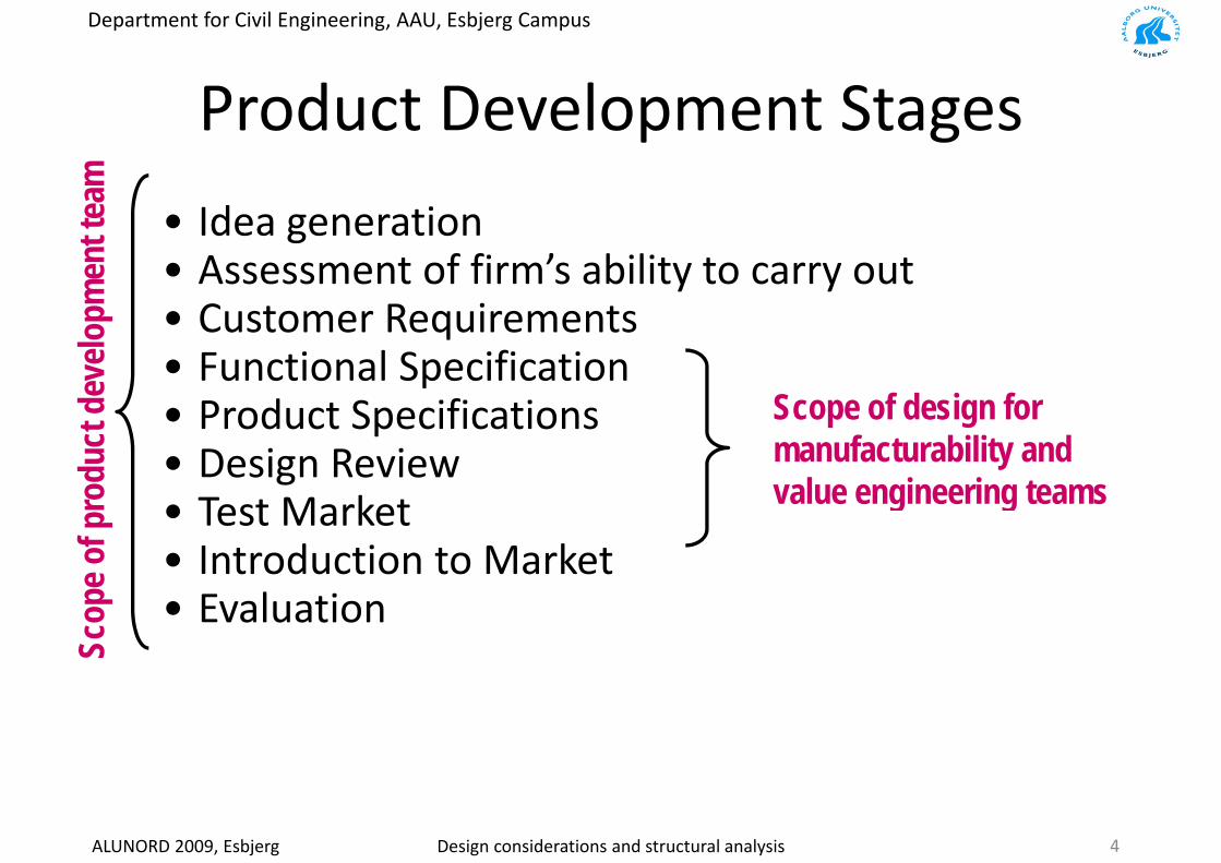
P d t D l t StProduct Development Stagesam
• Idea generation• Assessment of firm’s ability to carry outm
ent t
ea
y y• Customer Requirements• Functional Specificationev
elopm
p• Product Specifications• Design Reviewdu
ct d
e Scope of design for manufacturability and
l i i tg
• Test Market• Introduction to Markete o
f pro
d value engineering teams
• Evaluation
Scop
e
ALUNORD 2009, Esbjerg Design considerations and structural analysis 4
Department for Civil Engineering, AAU, Esbjerg Campus
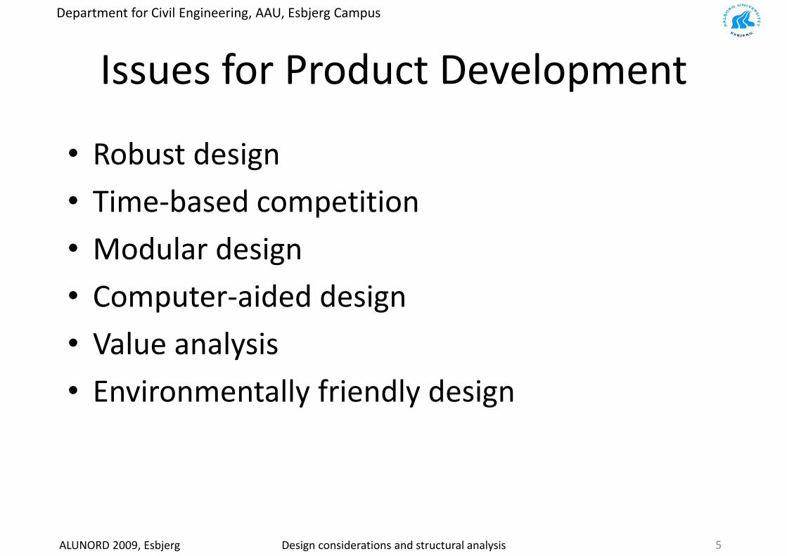
I f P d t D l tIssues for Product Development
• Robust design
• Time‐based competition
• Modular design• Modular design
• Computer‐aided designp g
• Value analysis
• Environmentally friendly design
ALUNORD 2009, Esbjerg Design considerations and structural analysis 5
Department for Civil Engineering, AAU, Esbjerg Campus
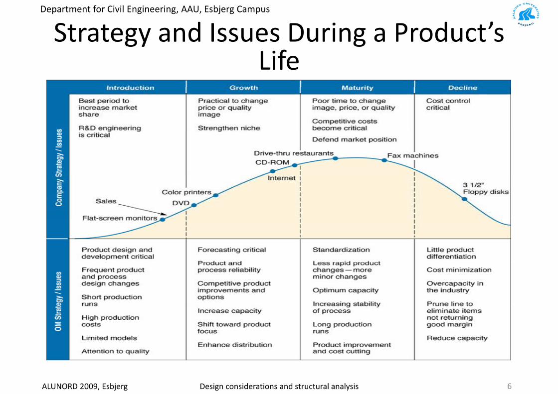
Strategy and Issues During a Product’s gy gLife
ALUNORD 2009, Esbjerg Design considerations and structural analysis 6
Department for Civil Engineering, AAU, Esbjerg Campus
Improving The Design Process: Design p g g gFor Manufacture (DFM)
• Design a product for easy & economical production
C id f t bilit l i th d i h• Consider manufacturability early in the design phase
• Identify easy‐to‐manufacture product‐design y y p gcharacteristics
• Use easy to fabricate & assemble components• Use easy to fabricate & assemble components
• Integrate product design with process planning
ALUNORD 2009, Esbjerg Design considerations and structural analysis 7

Department for Civil Engineering, AAU, Esbjerg Campus
DFM G id liDFM Guidelines
1. Minimize the number of parts2 D l d l d i2. Develop a modular design3. Design parts for multi‐use3. Design parts for multi use4. Avoid separate fasteners5. Eliminate adjustments6 Design for top‐down assembly6. Design for top‐down assembly7. Design for minimum handling8. Avoid tools
ALUNORD 2009, Esbjerg Design considerations and structural analysis 8
Department for Civil Engineering, AAU, Esbjerg Campus
DFM G id li ( )DFM Guidelines (continued)
9. Minimize subassemblies
10. Use standard parts when possible
11 Simplify operations11. Simplify operations
12. Design for efficient and adequate testingg q g
13. Use repeatable & understood processes
14. Analyze failures
15 Ri l l15. Rigorously assess value
ALUNORD 2009, Esbjerg Design considerations and structural analysis 9
Department for Civil Engineering, AAU, Esbjerg Campus
St t l d i iStructural design issues
• Some design considerations:– Structural design criteria – failure modesStructural design criteria failure modes– Stress concentration – notch sensitivityBuckling/instability modal analysis– Buckling/instability – modal analysis
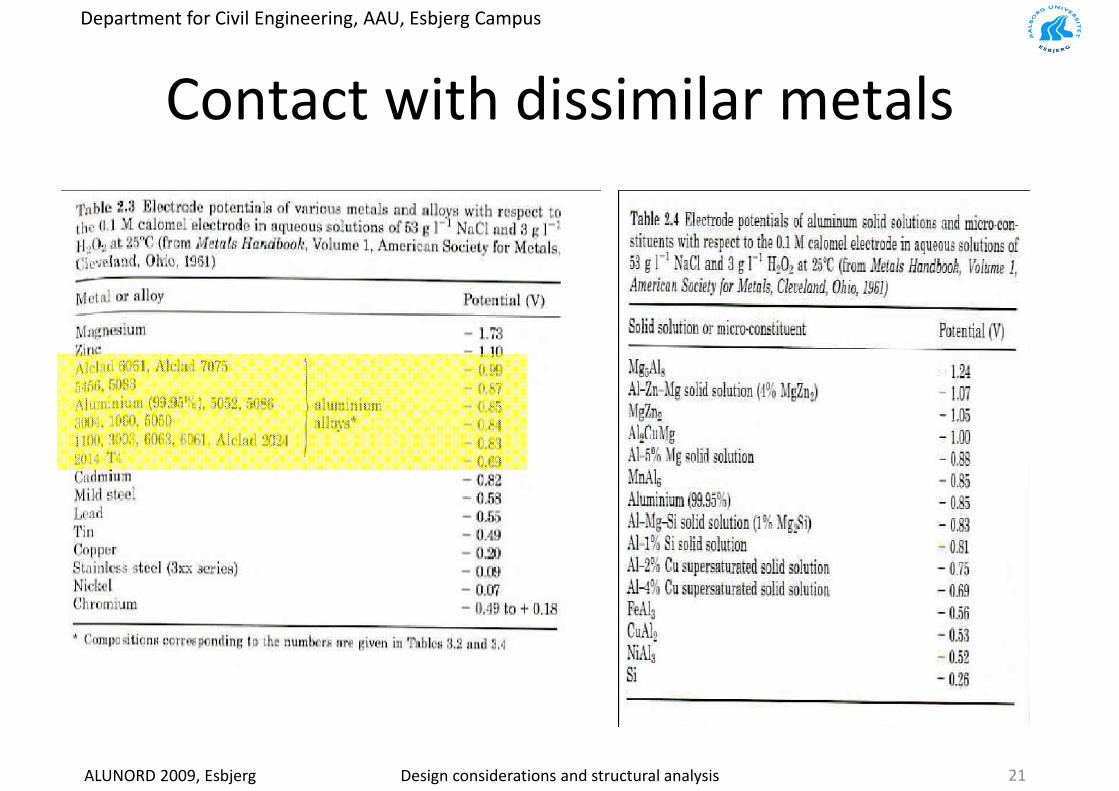
– Eigen‐frequency – modal analysisContact with dissimilar metals– Contact with dissimilar metals
– Welding and temperature affect mechanical properties C i– Corrosion
– Fatigue considerations:f• No endurance limit for Aluminum in S‐N diagram
• Consider fracture toughness properties for the material
ALUNORD 2009, Esbjerg Design considerations and structural analysis 10

Department for Civil Engineering, AAU, Esbjerg Campus
F il M dFailure Modes• Deformation
– Modulus of Elasticity (E [MPa])Modulus of Elasticity (E [MPa])– Moment of inertia
• Yielding– Yielding Stress (Re [MPa])– Modulus of Elasticity (E [MPa])– Modulus of Elasticity (E [MPa])
• Ductile rupture– Yielding Stress (Re [MPa])– Modulus of Elasticity (E [MPa])
B ittl f t• Brittle fracture– Ultimate Tensile Stress (Rm [MPa])– Modulus of Elasticity (E [MPa])
• Fatigue g– Endurance limit– Design approach, e.g. Fail‐safe, Damage Tolerant– Fracture toughness
• Corrosion• Wear• Impact• Creepp• Buckling
– Moment of inertia– Modulus of Elasticity (E [MPa])
• Stress corrosion (synergistic)
ALUNORD 2009, Esbjerg Design considerations and structural analysis
• Stress corrosion (synergistic)
11
Department for Civil Engineering, AAU, Esbjerg Campus
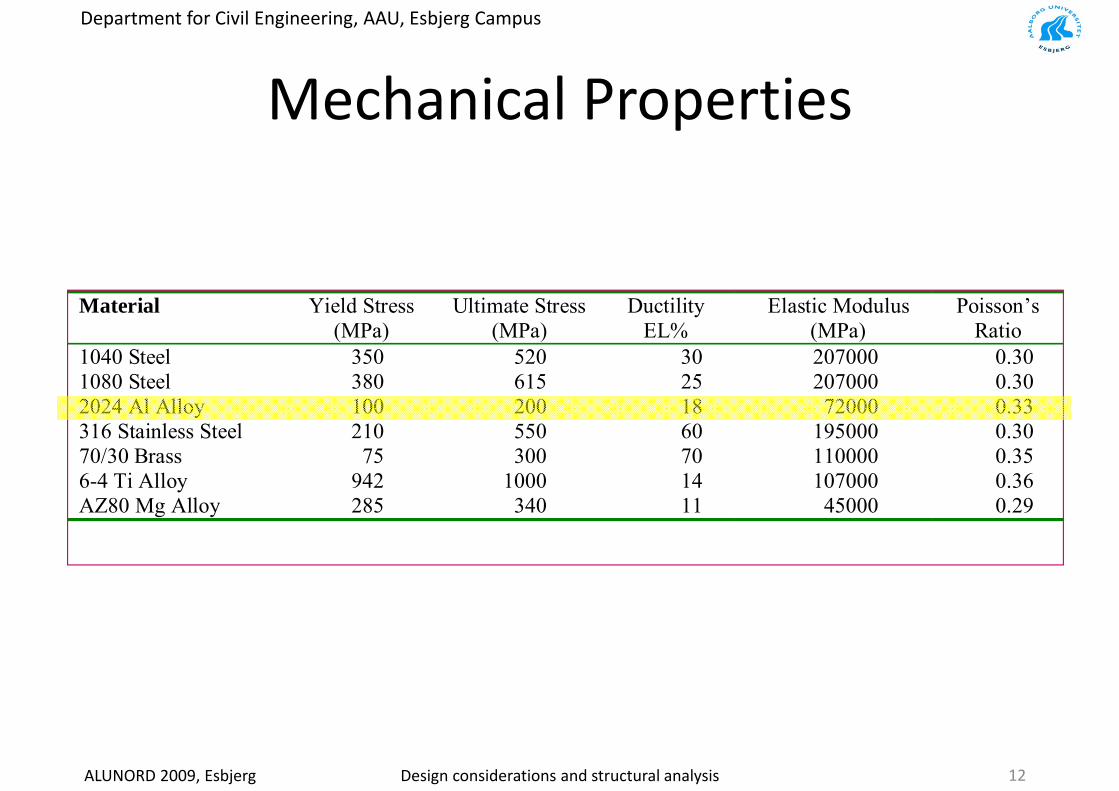
M h i l P tiMechanical PropertiesM t l i l d ( ft) ditiMetals in annealed (soft) condition
Material Yield Stress(MPa)
Ultimate Stress(MPa)
DuctilityEL%
Elastic Modulus(MPa)
Poisson’sRatio
1040 St l 350 520 30 207000 0 301040 Steel 350 520 30 207000 0.301080 Steel 380 615 25 207000 0.302024 Al Alloy 100 200 18 72000 0.33316 Stainless Steel 210 550 60 195000 0.3070/30 Brass 75 300 70 110000 0.356-4 Ti Alloy 942 1000 14 107000 0.36AZ80 Mg Alloy 285 340 11 45000 0.29
ALUNORD 2009, Esbjerg Design considerations and structural analysis 12
Department for Civil Engineering, AAU, Esbjerg Campus
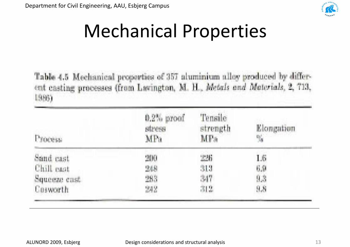
M h i l P tiMechanical Properties
ALUNORD 2009, Esbjerg Design considerations and structural analysis 13

Department for Civil Engineering, AAU, Esbjerg Campus
D i it iDesign criteria
ALUNORD 2009, Esbjerg Design considerations and structural analysis 14

Department for Civil Engineering, AAU, Esbjerg Campus
St t ti t h iti itStress concentration – notch sensitivity
ALUNORD 2009, Esbjerg Design considerations and structural analysis 15
Department for Civil Engineering, AAU, Esbjerg Campus
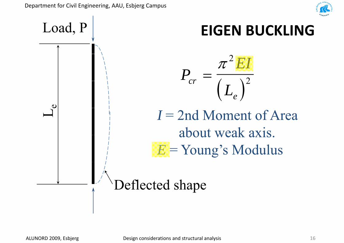
Load P EIGEN BUCKLINGLoad, P EIGEN BUCKLING
( )P
EIcr =
π 2
2( )Lcr
e
2
eL e I = 2nd Moment of Areaabout weak axisabout weak axis.
E = Young’s Modulus
Deflected shapeDeflected shape
ALUNORD 2009, Esbjerg Design considerations and structural analysis 16
Department for Civil Engineering, AAU, Esbjerg Campus
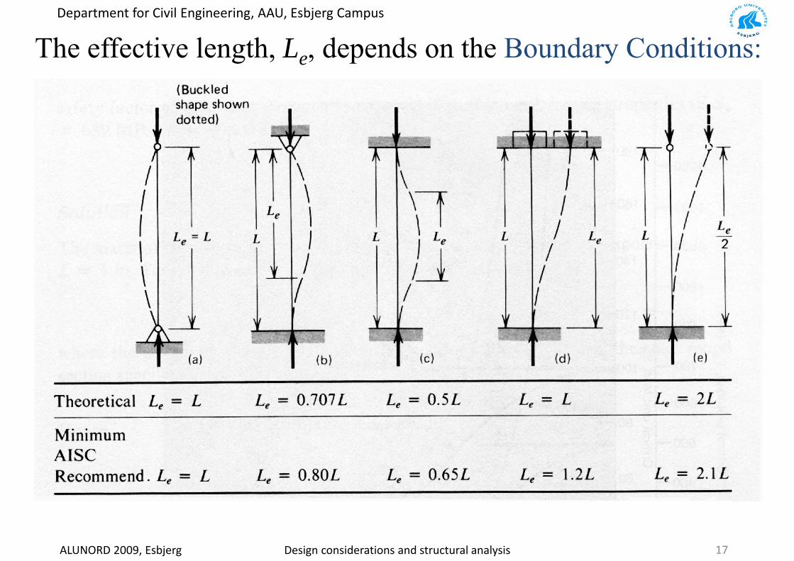
The effective length, Le, depends on the Boundary Conditions:g e p y
ALUNORD 2009, Esbjerg Design considerations and structural analysis 17
Department for Civil Engineering, AAU, Esbjerg Campus
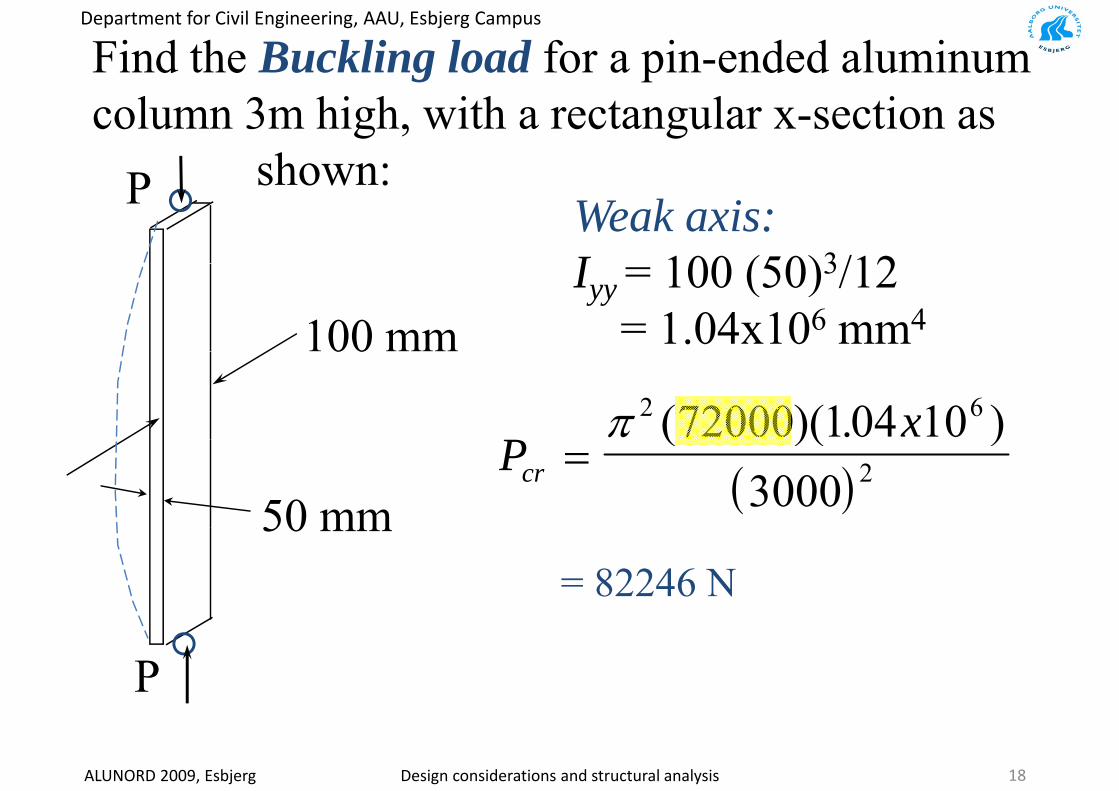
Find the Buckling load for a pin-ended aluminumcolumn 3m high, with a rectangular x-section as
shown:P shown:P Weak axis:I 100 (50)3/12
100 mmIyy = 100 (50)3/12
= 1.04x106 mm400
xπ 2 672000 104 10( )( . )
50 mm ( )Pcr = 23000
( )( )
50 mm= 82246 N
P
ALUNORD 2009, Esbjerg Design considerations and structural analysis 18

Department for Civil Engineering, AAU, Esbjerg Campus
D i Eff tDynamic EffectsStatic, i.e. acceleration ≈ 0
FKD =Static, i.e. acceleration 0
FKDDCDM ++ &&&Dynamic, i.e. acceleration ≠ 0
FKDDCDM =++
• Inertia force – mass times acceleration• Damping force – damping times velocity• Elastic Force – stiffness times deformation
• External force• Dynamic Effects
ALUNORD 2009, Esbjerg Design considerations and structural analysis 19
Dynamic Effects
Department for Civil Engineering, AAU, Esbjerg Campus
M d l A l iModal Analysis
• Avoid resonance
• Exploit resonance
• Assess structural stiffness• Assess structural stiffness
• Structural modal degrees of freedomg
• Further dynamic analyses
• etc.
ALUNORD 2009, Esbjerg Design considerations and structural analysis 20
Department for Civil Engineering, AAU, Esbjerg Campus
C t t ith di i il t lContact with dissimilar metals
ALUNORD 2009, Esbjerg Design considerations and structural analysis 21
Department for Civil Engineering, AAU, Esbjerg Campus
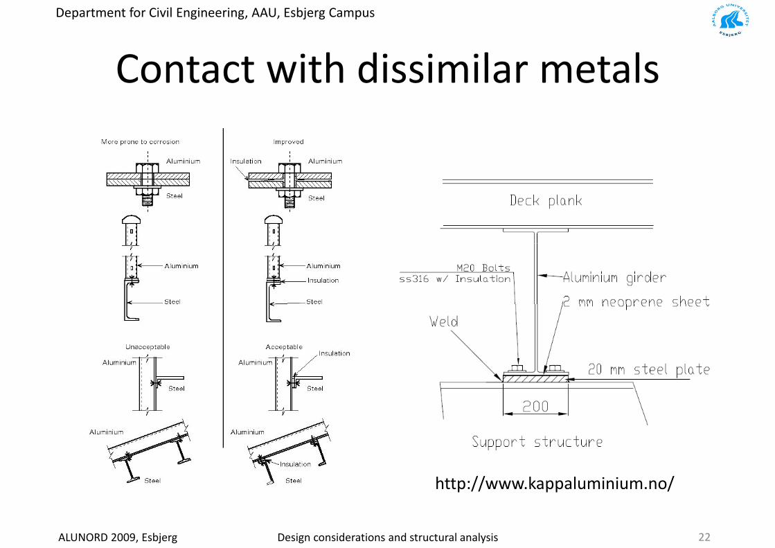
C t t ith di i il t lContact with dissimilar metals
http://www kappaluminium no/
ALUNORD 2009, Esbjerg Design considerations and structural analysis 22
http://www.kappaluminium.no/

Department for Civil Engineering, AAU, Esbjerg Campus
W ldiWelding
• If the base material has been cold worked prior to welding, the effect of work hardening isthe effect of work hardening is completely gone in the fusion zone due to remelting and is
ti ll l t i HAZ d tpartially lost in HAZ due to recrystallisation and grain growth.
• Note: Strength loss should be taken into account intaken into account in structural designs. (even Toughness) The harder the b t l th t th
Softening of workhardenedMaterial caused by weldingbase metal, the greater the
strength loss is.Material caused by welding(a) thermal cycles(b) strength or Fusion hardness profile
ALUNORD 2009, Esbjerg Design considerations and structural analysis 23
hardness profile.
Department for Civil Engineering, AAU, Esbjerg Campus
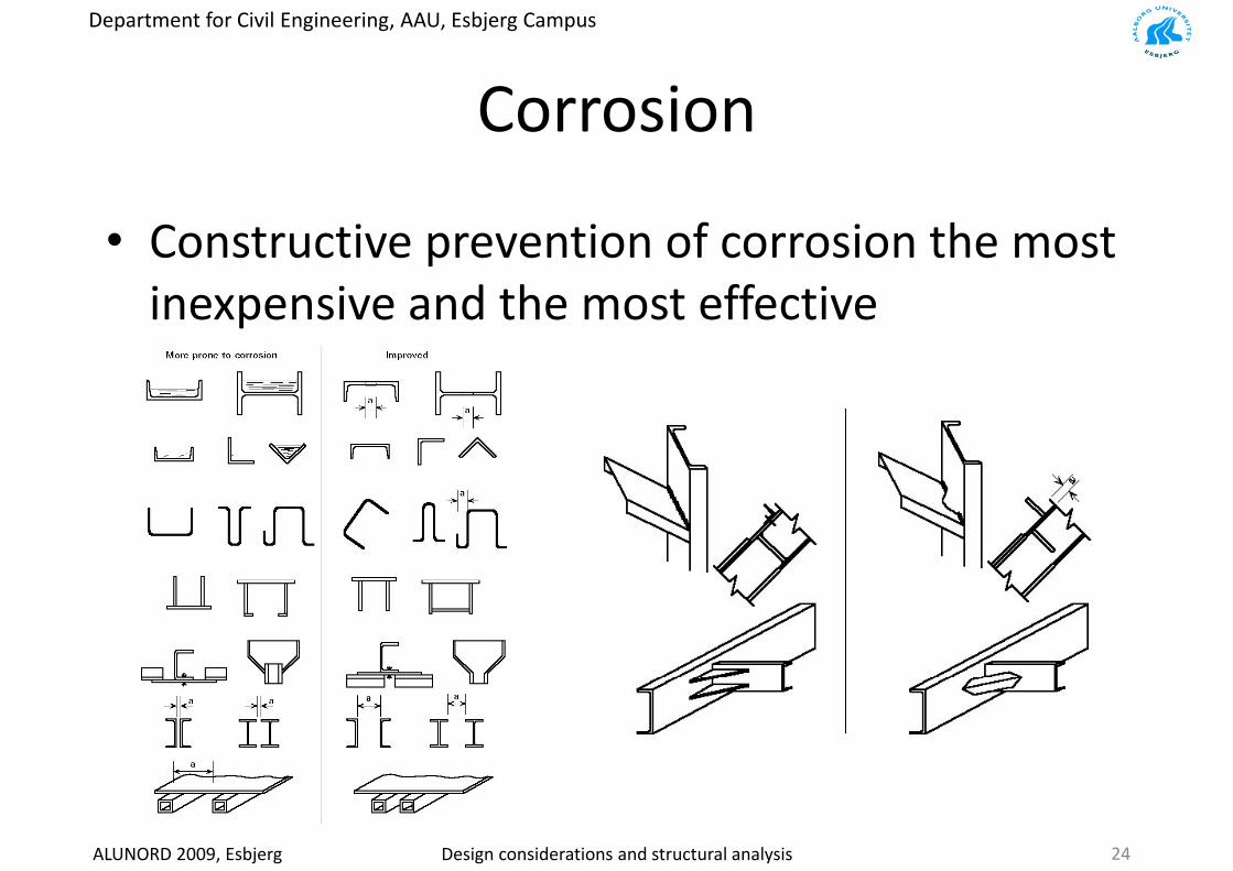
C iCorrosion
• Constructive prevention of corrosion the most i i d th t ff tiinexpensive and the most effective
ALUNORD 2009, Esbjerg Design considerations and structural analysis 24

Department for Civil Engineering, AAU, Esbjerg Campus
C iCorrosion
ALUNORD 2009, Esbjerg Design considerations and structural analysis 25
Department for Civil Engineering, AAU, Esbjerg Campus
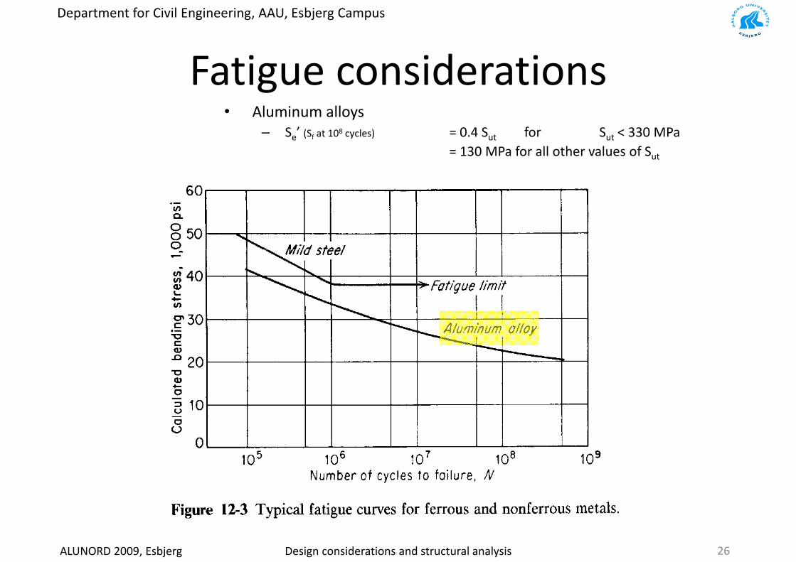
F ti id tiFatigue considerations• Aluminum alloys
– Se’ (Sf at 108 cycles) = 0.4 Sut for Sut < 330 MPa= 130 MPa for all other values of Sut
ALUNORD 2009, Esbjerg Design considerations and structural analysis 26
Department for Civil Engineering, AAU, Esbjerg Campus
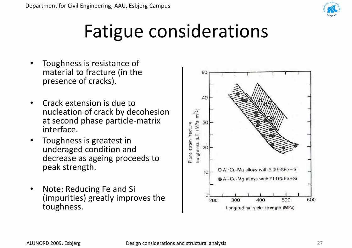
F ti id tiFatigue considerations• Toughness is resistance of
material to fracture (in the presence of cracks)presence of cracks).
• Crack extension is due to l ti f k b d h inucleation of crack by decohesion
at second phase particle‐matrix interface.T h i i• Toughness is greatest in underaged condition and decrease as ageing proceeds to
k t thpeak strength.
• Note: Reducing Fe and Si g(impurities) greatly improves the toughness.
ALUNORD 2009, Esbjerg Design considerations and structural analysis 27

Department for Civil Engineering, AAU, Esbjerg Campus
F ti id tiFatigue considerations• The improvement in tensile strength
is not always accompanied with increased fatigue strength in non‐g gferrous alloys.
• The more an alloy is dependent upon precipitation‐hardening for its tensile
h h l i f i istrength, the lower its fatigue ratio (endurance limit : tensile strength) becomes.
• Age hardened aluminium alloys• Age‐hardened aluminium alloys possess disappointing fatigue properties due to localised straining of precipitates under cyclic stressing. p p y gImproved by more uniformly dispersed precipitates to prevent coarse slips formation.
l b• An increase in dislocation density by thermo mechanical processing helps to improve fatigue performance
ALUNORD 2009, Esbjerg Design considerations and structural analysis 28
Department for Civil Engineering, AAU, Esbjerg Campus
Mi t t F ti R l ti hiMicrostructure‐Fatigue Relationships
• Three major factors.1: geometry of the specimen (previous slide); anything on the
surface that is a site of stress concentration will promote crack formation (shorten the time required for nucleation of cracks).
2: defects in the material; anything inside the material that can reduce the stress and/or strain required to nucleate a crack ( h t th ti i d f l ti f k )(shorten the time required for nucleation of cracks).
3: dislocation slip characteristics; if dislocation glide is confined to3: dislocation slip characteristics; if dislocation glide is confined to particular slip planes (called planar slip) then dislocations can pile up at any grain boundary or phase boundary. The head of the pile up is a stress concentration which can initiate a crackthe pile‐up is a stress concentration which can initiate a crack.
ALUNORD 2009, Esbjerg Design considerations and structural analysis 29

Department for Civil Engineering, AAU, Esbjerg Campus
C ti it ff t f tiCasting porosity affects fatigueGravity cast versussqueeze cast
[Polmear]
qversuswroughtAl-7010Al 7010
• Casting tends to result in porosity. Pores are effective sites for nucleation of fatigue cracks Castings thus tend to have lower fatigue resistance (asfatigue cracks. Castings thus tend to have lower fatigue resistance (as measured by S‐N curves) than wrought materials.
• Casting technologies, such as squeeze casting, that reduce porosity tend to
ALUNORD 2009, Esbjerg Design considerations and structural analysis 30
eliminate this difference.
Department for Civil Engineering, AAU, Esbjerg Campus
ALUNORD 2009, Esbjerg Design considerations and structural analysis 31
Department for Civil Engineering, AAU, Esbjerg Campus
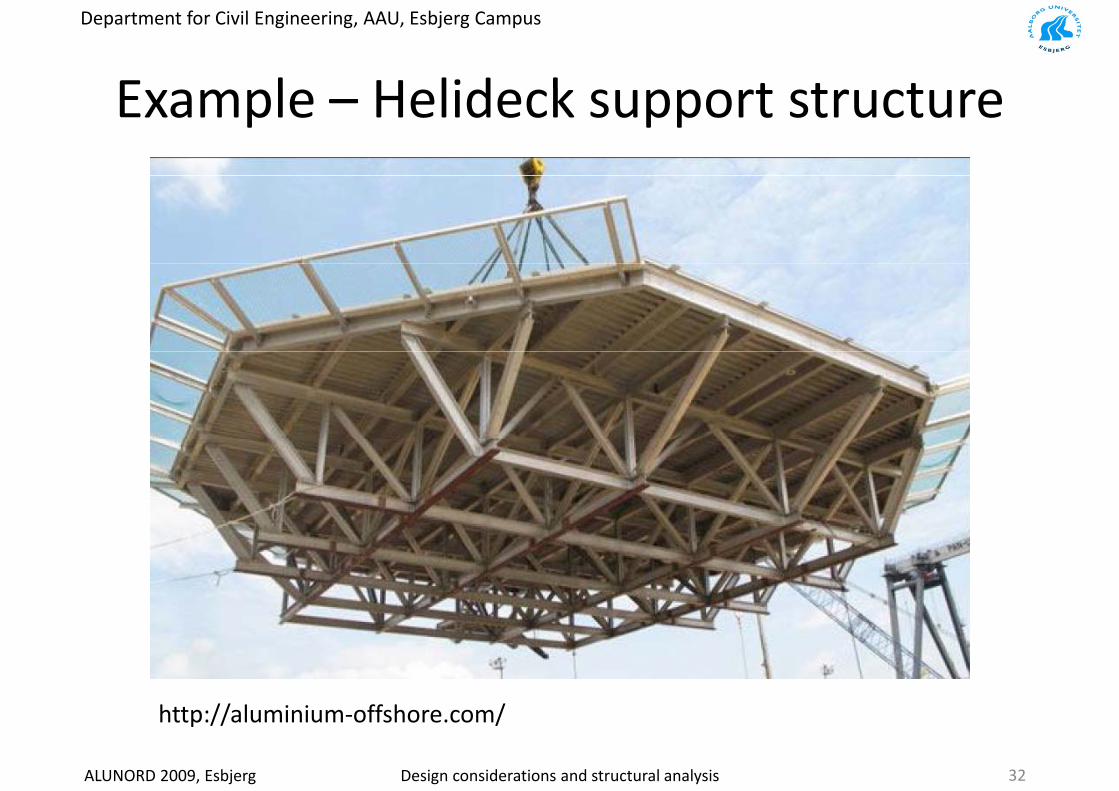
E l H lid k t t tExample – Helideck support structure
ALUNORD 2009, Esbjerg Design considerations and structural analysis 32
http://aluminium‐offshore.com/

Department for Civil Engineering, AAU, Esbjerg Campus
E l H lid k t t tExample – Helideck support structure
Aluminium SteelEN AW 6082‐T6 EN 10 025 S355 K2 G3AlSi1MgMn alloy Mn, Si, P, S alloying elements
ALUNORD 2009, Esbjerg Design considerations and structural analysis 33

Department for Civil Engineering, AAU, Esbjerg Campus
E l H lid k t t tExample – Helideck support structure
Aluminium• Welding reduce strength in HAZ up to 30
Steel• Welding require special considerations in• Welding reduce strength in HAZ up to 30‐
50% and it is difficult to improve• Inspection is required (NDT)• SCF, i.e. welding and geometrical sharp edges
• Welding require special considerations in respect to HAZ
• Inspection is required (NDT)• SCF, i.e. welding and geometrical sharp edges
(notches) increase the stress level significantly
• Price– Can be increased by introducing welding, i.e.
(notches) increase the stress level significantly
• Price– Can be increased by introducing welding, i.e. y g g,
increased requirements to inspection• Weight
– Depends on the structural behaviour – in this case the use of bolts provide a very effective
y g g,increased requirements to inspection
• Weight– Depends on the structural behaviour – in this
case the use of cylindrical members provide a p yload‐carrying structure
– Resulting weight = 12000kg• Serviceability
– Easier to transport
y pvery effective load‐carrying structure
– Resulting weight = 24000kg• Serviceability
– Structural analysis on base structure requiredp• Manufacturability
– No additional corrosion considerations• Resale
y q• Manufacturability
– Require additional corrosion considerations• Resale
ALUNORD 2009, Esbjerg Design considerations and structural analysis 34
Department for Civil Engineering, AAU, Esbjerg Campus
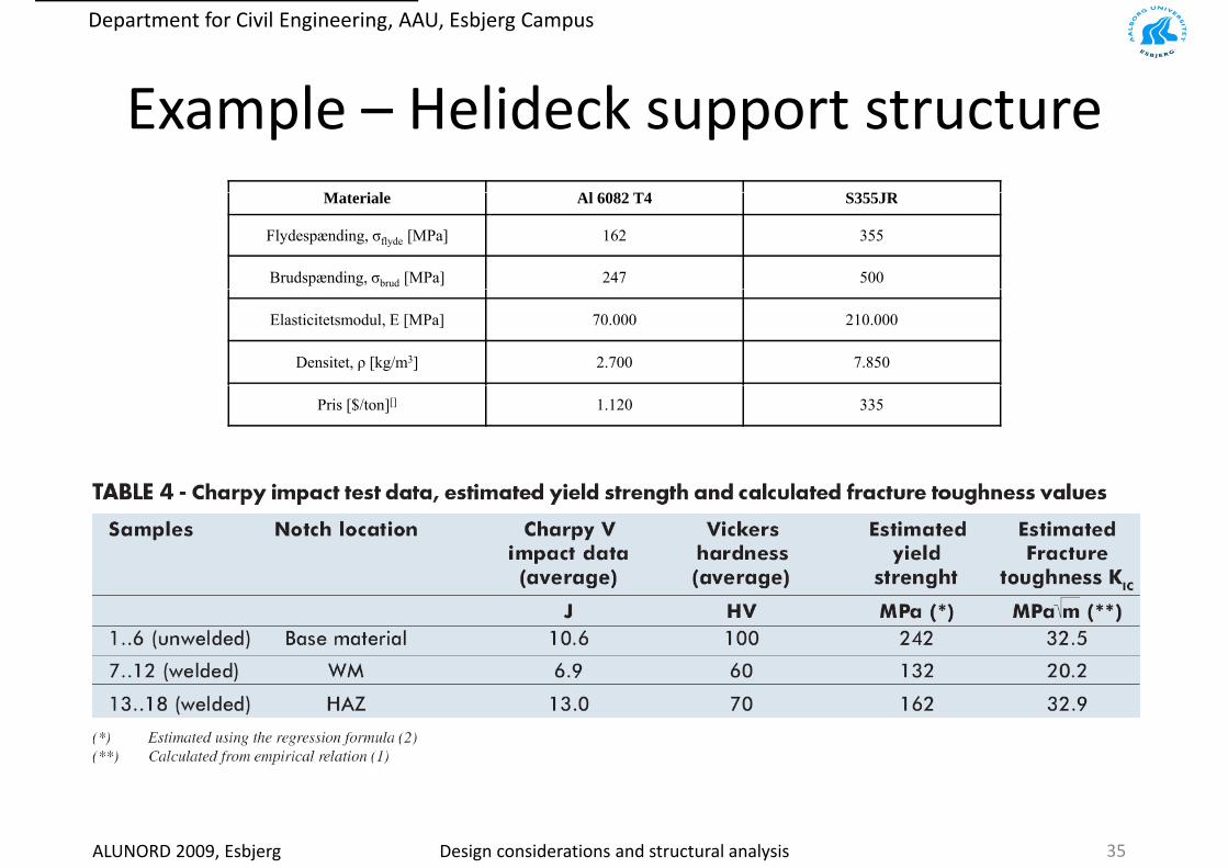
E l H lid k t t tExample – Helideck support structureM i l Al 6082 T4 S355JRMateriale Al 6082 T4 S355JR
Flydespænding, σflyde [MPa] 162 355
Brudspænding, σbrud [MPa] 247 500
Elasticitetsmodul, E [MPa] 70.000 210.000
Densitet, ρ [kg/m3] 2.700 7.850
Pris [$/ton][] 1.120 335
ALUNORD 2009, Esbjerg Design considerations and structural analysis 35
Department for Civil Engineering, AAU, Esbjerg Campus
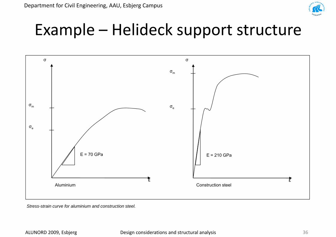
E l H lid k t t tExample – Helideck support structure
σm
σσ
σ σe
σe
σm
E = 210 GPaE = 70 GPa
εConstruction steel
εAluminium Construction steelAluminium
Stress-strain curve for aluminium and construction steel.
ALUNORD 2009, Esbjerg Design considerations and structural analysis 36

Department for Civil Engineering, AAU, Esbjerg Campus
Example – Luggage lift
ALUNORD 2009, Esbjerg Design considerations and structural analysis

Department for Civil Engineering, AAU, Esbjerg Campus
E l L liftExample – Luggage lift
ALUNORD 2009, Esbjerg Design considerations and structural analysis 38

Department for Civil Engineering, AAU, Esbjerg Campus
E l L liftExample – Luggage lift
ALUNORD 2009, Esbjerg Design considerations and structural analysis 39
Department for Civil Engineering, AAU, Esbjerg Campus
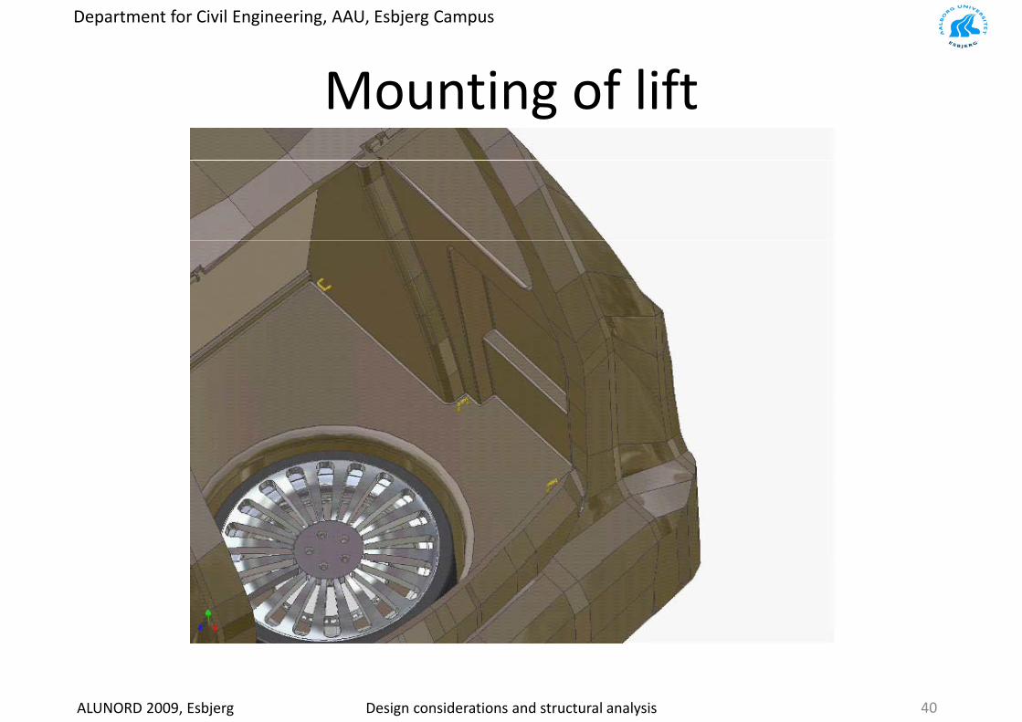
M ti f liftMounting of lift
ALUNORD 2009, Esbjerg Design considerations and structural analysis 40
Department for Civil Engineering, AAU, Esbjerg Campus
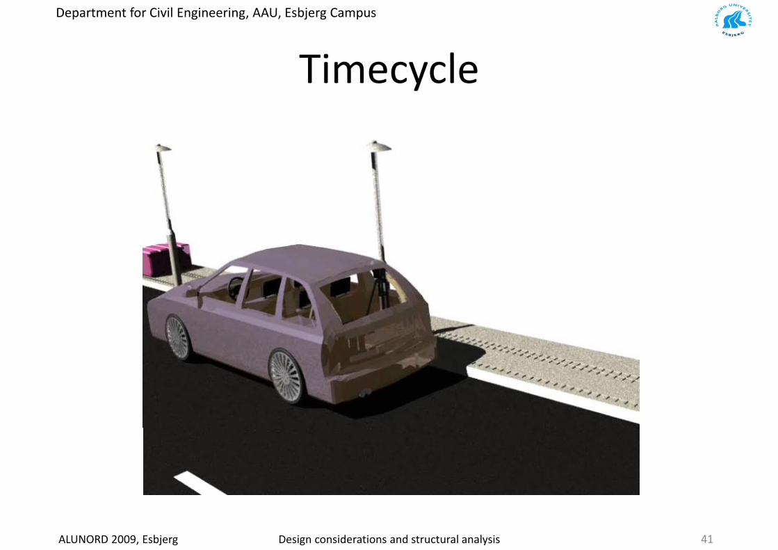
Ti lTimecycle
ALUNORD 2009, Esbjerg Design considerations and structural analysis 41
Department for Civil Engineering, AAU, Esbjerg Campus
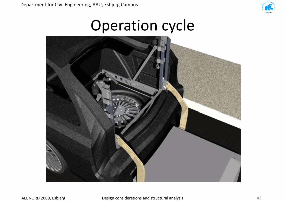
O ti lOperation cycle
ALUNORD 2009, Esbjerg Design considerations and structural analysis 42
Department for Civil Engineering, AAU, Esbjerg Campus
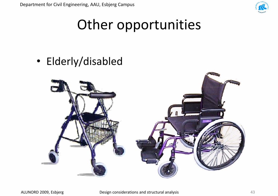
Oth t itiOther opportunities
• Elderly/disabledy/
ALUNORD 2009, Esbjerg Design considerations and structural analysis 43
Department for Civil Engineering, AAU, Esbjerg Campus
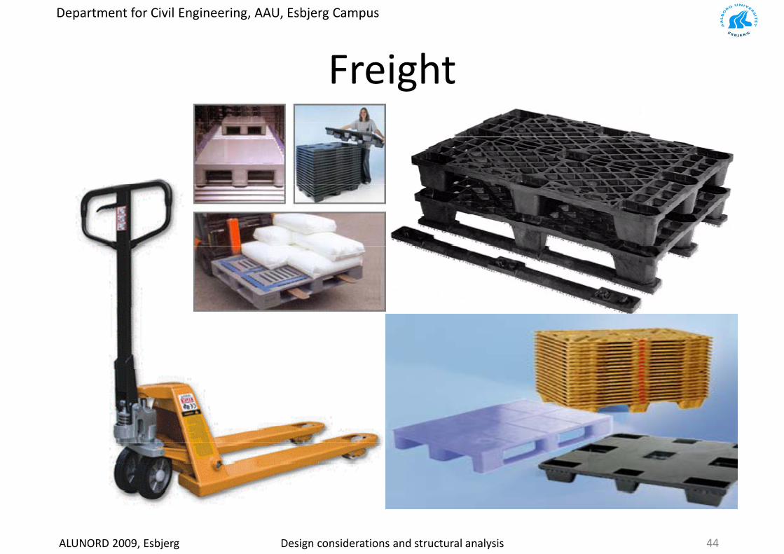
F i htFreight
ALUNORD 2009, Esbjerg Design considerations and structural analysis 44

Department for Civil Engineering, AAU, Esbjerg Campus
M t i l l tiMaterial selection
D i h k f t t l t• Designcheck of structural components
• Critical areasCritical areas
• Manufacturing
ALUNORD 2009, Esbjerg Design considerations and structural analysis 45

Department for Civil Engineering, AAU, Esbjerg Campus
L diLoading area
M t i l l i i h• Material – aluminium chosen
• Profil chosen (area moment of inertia)Profil chosen (area moment of inertia)
• Wear
ALUNORD 2009, Esbjerg Design considerations and structural analysis
• Coating on rail46
Department for Civil Engineering, AAU, Esbjerg Campus
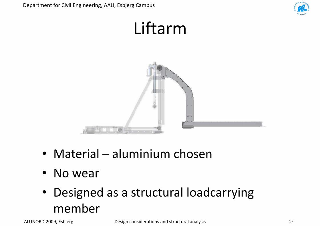
LiftLiftarm
M t i l l i i h• Material – aluminium chosen
• No wearNo wear
• Designed as a structural loadcarrying
ALUNORD 2009, Esbjerg Design considerations and structural analysis
member47
Department for Civil Engineering, AAU, Esbjerg Campus
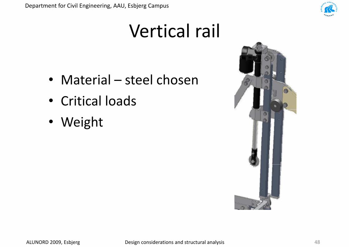
V ti l ilVertical rail
• Material – steel chosenMaterial steel chosen
• Critical loads
• Weight
ALUNORD 2009, Esbjerg Design considerations and structural analysis 48
Department for Civil Engineering, AAU, Esbjerg Campus
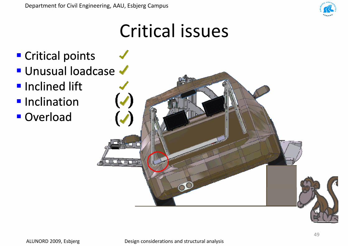
C iti l iCritical issuesCriticalCritical pointspointsCriticalCritical points points UnusualUnusual loadcaseloadcase
l dl d l fl fInclinedInclined liftliftInclinationInclinationOverloadOverload
ALUNORD 2009, Esbjerg Design considerations and structural analysis49

Department for Civil Engineering, AAU, Esbjerg Campus
S f tSafety
SafetySafetySafetySafetyEmergencyEmergency stopstopShieldingShieldingShieldingShielding
ALUNORD 2009, Esbjerg Design considerations and structural analysis 50
Department for Civil Engineering, AAU, Esbjerg Campus
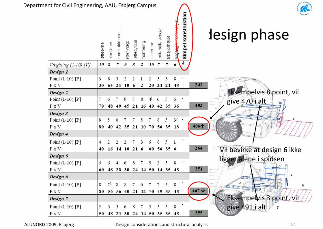
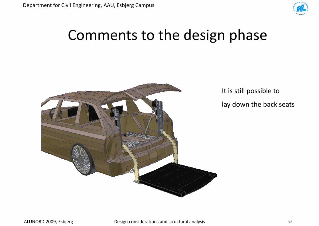
Comments to the design phase
Eksempelvis 8 point, vil give 470 i altgive 470 i alt
Vil bevirke at design 6 ikke gligger alene i spidsen
Eksempelvis 3 point, vil
ALUNORD 2009, Esbjerg Design considerations and structural analysis
give 491 i alt
51
Department for Civil Engineering, AAU, Esbjerg Campus
Comments to the design phase
It is still possible to
lay down the back seats
ALUNORD 2009, Esbjerg Design considerations and structural analysis 52

Department for Civil Engineering, AAU, Esbjerg Campus
E l i l tiExample ‐ simulation
ALUNORD 2009, Esbjerg Design considerations and structural analysis 53
Department for Civil Engineering, AAU, Esbjerg Campus
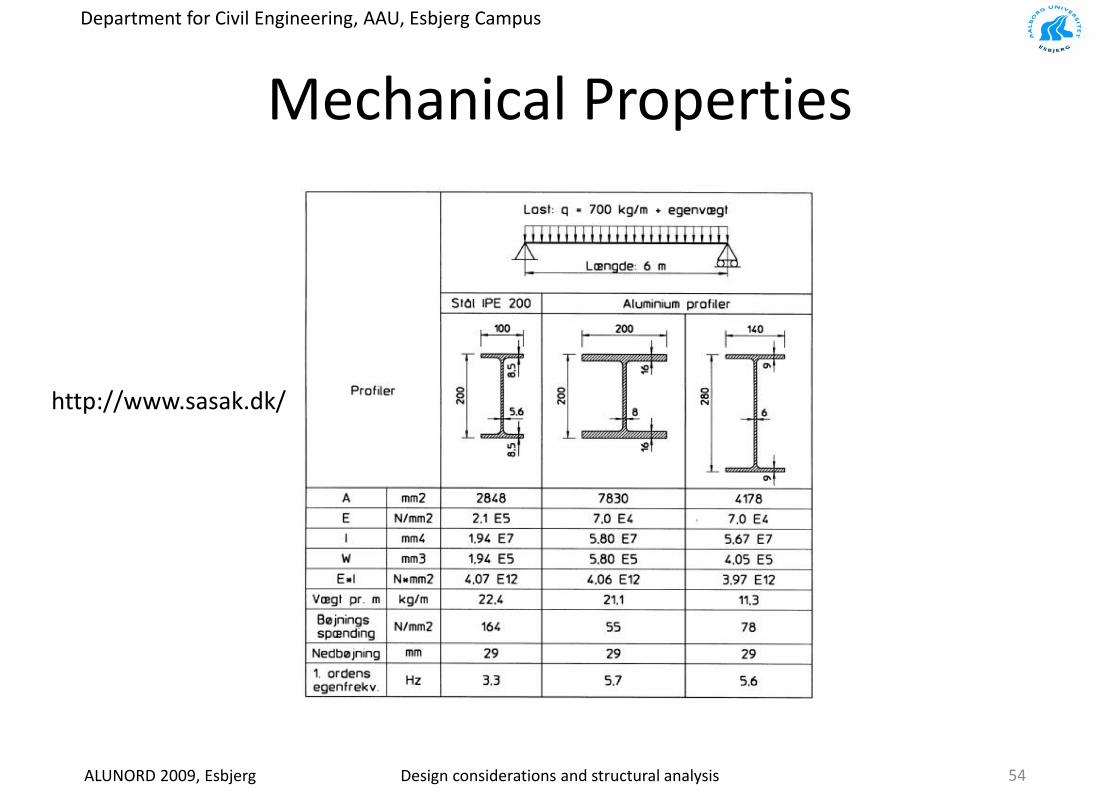
M h i l P tiMechanical Properties
http://www.sasak.dk/
ALUNORD 2009, Esbjerg Design considerations and structural analysis 54

Department for Civil Engineering, AAU, Esbjerg Campus
THANK YOU FOR YOUR ATTENTION
ALUNORD 2009, Esbjerg Design considerations and structural analysis 55