amcom mk66 guidance module 04-12-2005. software block diagram data handler imu processinggps...
TRANSCRIPT

AMCOM MK66 AMCOM MK66 Guidance ModuleGuidance Module
04-12-200504-12-2005

Software Block DiagramSoftware Block Diagram
Data Handler
IMU Processing GPS Processing RMS Control
Serial I/O Ctrl
Parallel Ctrl.Actuate, Deploy
Course Plot/Corr.
RS-232 Dev

SimulationSimulationPhase 1Phase 1
RS232
FPGA “simulator”(program runs here)
Navionic input simulation
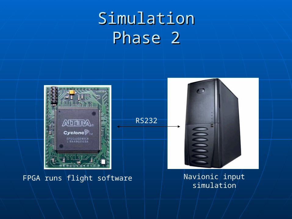
SimulationSimulationPhase 2Phase 2
RS232
FPGA runs flight software Navionic input simulation

Servomotor ControlServomotor Control
Altera knows NOTHING of servomotor Altera knows NOTHING of servomotor positionposition
FPGA sends control line to FPGA sends control line to servomotor, continues to hold line servomotor, continues to hold line level.level.
Servomotor stops at designated Servomotor stops at designated position while line level is high.position while line level is high.

ServoblockServoblock
Servo
Parallel Port
Ctrl. Logic
Power Conv.
Feedback

Complete Avionics ModuleComplete Avionics Module Avionics Module
ADDITION TO HYDRA 70 ROCKET

Male and Female Male and Female InterfacesInterfaces
-Acme Stub Threads with a pitch of 6
-Half inch interference zones for placement in warhead/motor
-All dimensions made to match current rocket interfaces precisely
-Threaded push pins used to secure interfaces to module shell (not shown)

Canard AssemblyCanard AssemblyCanard Assembly

Canard Assembly Cont…Canard Assembly Cont…
Canard and actuation mechanism shown
- actuation gear attaches to assembly here

CANARD
Machined from a single piece of material for simplicity and added strength

ACTUATION MECHANISM COMPONENTS
Springs for deployment and locking mechanism to prevent canard from closing once deployed


Yellow piece here is attachment point to frame

CANARD IN CLOSED POSITION

Internal Frame
-Machined from solid piece of aluminum
-Allows for placement of IMU, GPS, and CPU
-Machined from solid piece of aluminum
-Allows for placement of IMU, GPS, and CPU
Internal Frame

CANARD MOUNTING LOCATION
Mounting bar offset 45 deg from frame to accommodate canard assembly and servomotors

Placement of Canard Assembly

Placement of Servomotors
-Mounts for servomotors currently being designed
-Servos mounted at angle to line up proper angle with actuation gear

Packaging inside module shell

FRAME WITH ELECTRONICS
-Thermal battery and insulation (red) attach to end of frame
-IMU attaches inside of frame
-Thermal battery and insulation (red) attach to end of frame
-IMU attaches inside of frame
FRAME WITH ELECTRONICS

GPS and CPU attach on either side of frame

AVIONICS MODULE INTERNAL VIEWAVIONICS MODULE INTERNAL VIEW