amfmtv - americanradiohistory.com · integration of each part of the system into the most...
TRANSCRIPT

AMFMTV BROADCAST EQUIPMENT
McCurdy Radio Industries, Inc. 57 North Putnam Street Danvers, Massachusetts 01923
(617) 744-6411

ISSIWO 1111SSUSe
IgCuiff5r

CX?Viti3\\4ee ******%
111111111111111111
111111111111111111
111, , Y' ! **S1
11011111110
[email protected] e SS «tee%
SS 7600 CUSTOM AUDIO CONSOLE Capable of accommodating up to 20 mono or 12 stereo mixer channels all with slide attenuators. Multiple input configurations available. Capability of supplying multiple outputs for multi- track tape recorders. Monitor feeds and cue system included as standard features. Options include echo -send, equalization insert and sub -masters.
SS 7500
8 Stereo mixer channels equipped with slide attenuators. 2 program channels each with VU meter, line key auxiliary and headset outputs. Stereo Record/Audition Buss.
Remote line input switcher. Stereo monitor channel with selectable External inputs.
Cue Systems with External input switching options include mono channels with VU meter, talk -back facility, compressors and equalizers.
SS 7400
12 Mixer, 2 channel mono audio console. 2 selectable inputs per mixer for a total of 24 inputs. All input channels utilize slide attenuators and by selection of optional input amplifiers each channel can accommodate low, medium or high-level inputs. The built-in cue system provides for auxiliary inputs as well as the internal functions. Push-button selection on control room monitors and studio monitors are standard. Options include mic. on/off relays, compressors and equalizers.
SS 4386A 6 Mixer channels mono, all equipped with pre -amplifiers and slide attenuators. All operating controls arranged for optimum separation combined with grouping of related functions. A choice of 3 -input amplifiers for different input level applications, feed a balanced mixer bus to eliminate noise pick-up within the console. A self-contained 2 watt cue system is included and can be used to select any input by means of push -buttons.
SS 4388A 8 mixer channels mono, all equipped with pre -amplifiers and rotary step attenuators. 2 Inputs per mixer channel with a choice of 3 -Input amplifiers for microphone or high-level applications. Balanced mixer bus.
Complete cue system including amplifier and speaker with full monitor control capability for feeding any McCurdy external monitor speaker. Provision for optional console. Mounted recessed push -buttons for machine control functions.
SS 4312 12 Mixer Channels Mono, all equipped with pre -amplifiers and rotary attenuators. 2 Program Channels, each with VU Meter and Line Keys.
2 Inputs per Mixer Channel, with a choice of 3 -Input amplifiers for microphone, or high-level applications. Channels 11 and 12 have additional remote inputs available. Complete Cue system including amplifier and speaker.

8S//OO
The SS 7700 series of television production and recording consoles is a logical extension to the McCurdy package approach to engineered systems.
Pre -engineering of the basic design within our production facility, assists the customer to easily determine from his requirements, both the general mechanical and electrical layout for his particular application. The design criteria of the SS 7700 series basic format allows for easy expansion to a maximum of 26 functional channels, which may consist of almost any mix of input channels, submasters and masters. McCurdy manufactured plug-in modules may be used in any or all of the functional channels. Space is available within the standard unit, for applications requiring complex fold -back, echo -send and monitor mix -down functions. An optional companion housing, styled to the basic console, is also available to accommodate the patching required for some applications. Therefore, the flexibility accorded the basic design by these features, allows the total panel layout to be human -engineered for maximum versatility and efficiency.
Functions available within each channel include: Echo -sends Straight-line faders Sensitivity Solo and Cue busses Phase reversal Sub or Master Assign pushbuttons.
A full range of auxiliary functions, such as remote controls, are available to ensure that the total design is completely integrated to the user's requirements.

cCU RDY
The McCurdy package approach to the engineering of a system allows the user to easily determine the best selection of standard components to fulfill his requirements.
All aspects of the broadcast function from news booth to full TV or record production can be met with the minimum of interface between snits. A full range of furniture allows for the integration of each part of the system into the most convenient working package.
Optional components including disc reproducers, reel tape housings and cartridge tape housings designed for instant operational accessability, combine with any of the consoles shown to fulfill the basic needs of the broadcaster.
Each system is fully pretested as a total unit and will meet or exceed all broadcast specifications.
Stereo package shown contains: 2 -SS 3158 turntables, 1 -SS 7500 console, 1 -SA 10044 cartridge tape housing, 1 -SA 10041 reel -tape housing & ITC tape equipment.
30
50
75
x100 Hz
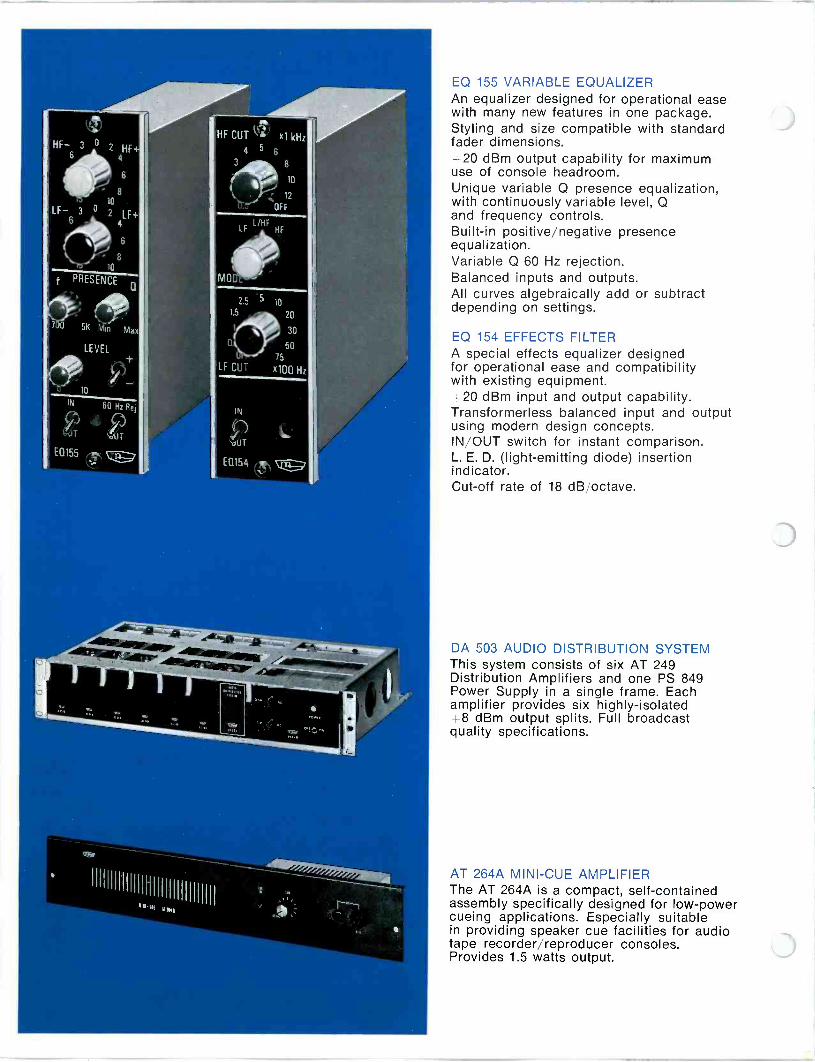
EQ 155 VARIABLE EQUALIZER An equalizer designed for operational ease with many new features in one package. Styling and size compatible with standard fader dimensions. +20 dBm output capability for maximum use of console headroom. Unique variable Q presence equalization, with continuously variable level, Q and frequency controls. Built-in positive/negative presence equalization. Variable Q 60 Hz rejection. Balanced inputs and outputs. All curves algebraically add or subtract depending on settings.
EQ 154 EFFECTS FILTER A special effects equalizer designed for operational ease and compatibility with existing equipment. +20 dBm input and output capability. Transformerless balanced input and output using modern design concepts. IN/OUT switch for instant comparison. L. E. D. (light -emitting diode) insertion indicator. Cut-off rate of 18 dB/octave.
DA 503 AUDIO DISTRIBUTION SYSTEM This system consists of six AT 249 Distribution Amplifiers and one PS 849 Power Supply in a single frame. Each amplifier provides six highly -isolated +8 dBm output splits. Full broadcast quality specifications.
AT 264A MINI -CUE AMPLIFIER The AT 264A is a compact, self-contained assembly specifically designed for low -power cueing applications. Especially suitable in providing speaker cue facilities for audio tape recorder/reproducer consoles. Provides 1.5 watts output.

am -fm -tv broadcast audio equipment
cCURDY McCURDY RADIO INDUSTRIES 108 Carnforth Road Toronto 16 Ontario . (416) 751-6262 1051 Clinton Street Buffalo N.Y. 14206 (716) 854-6700

a complete broadcast audio line
SOLID-STATE
CONSOLES... SS4360 DUAL -CHANNEL STUDIO CONSOLE Accommodates 34 inputs selectable to 10 mixers. Full 10 -watt monitoring. "Instant -select" cue-talkback system.
SS4370 DUAL -CHANNEL STEREO STUDIO CONSOLE e Accepts 28 stereo inputs to 8 mixers. Optional monaural chan- nel. 10 -watt Stereo Control Room monitor, with provision for Studio monitors. "Instant-select" cue-talkback system.
SS4388 DESK -TOP AUDIO CONSOLE Ideal for News Booth or DJ areas. 8 mixers, each accepting one HL and one LL input. One program channel. Complete cue system. Monitor control and feed for external amplifier. Four unwired utility keys, with provision for four more, plus optional pushbuttons for control of turntables, tapes, etc.
From Portable Equipment to complete TV Production Con- soles, Intercoms, and Switchers, McCurdy offers quality - de-
signed and built audio equipment for every commercial broad- cast requirement.
PE2400 PORTABLE AUDIO CONSOLE Provides for 8 low-level inputs or 4 high and 4 low-level inputs, selectable to 4 mixing channels; battery or ac operation. Pro- vides 110 dB gain, less than 0.5% harmonic distortion. Built- in test oscillator.
SS4386 DESK -TOP AUDIO CONSOLE
Designed for News Booth or DJ areas. 6 mixers, using slide attenuators, each mixer accepting one LL and one HL input. Complete cue system. Monitor and PA feed.
SS4395 DESK -TOP DUAL -CHANNEL AUDIO CONSOLE
Similar to SS4386 except 6 to 12 mixers with optional equal- izer insertion, two program channels, each with VU meter.
For nearly two decades, McCurdy Radio Industries has been a major supp!ier of broadcast audio equipment ranging from complete TV audio mixing consoles to the individual components which are used in such systems. McCurdy quality is manifest in performance, design features and attention to detail - appreciated by engineers who know the difference.
McCurdy is prepared to assist you with your requirements for complete studio equipment - standard or custom as well as to supply your needs for broadcast audio accessories.

INTERCOMS and SWITCHERS
CS7000 SERIES INTERCOM SYSTEM A completely solid-state professional intercom system utilizing a high -reliability reed relay switching matrix. A single type of input amplifier accommodates carbon microphone, dynamic microphone, or line level; also features optional compressor module. Output amplifier supplies 2 watts to 8-, 150-, or 600 -ohm lines. Standard input-output configurations are 10 x 10, 18 x 20, and 36 x 40. Custom systems may be engineered on request.
SM8 and SM18 AUDIO SWITCHERS Each Switching Module holds up to 8 relays to provide an 8
x 1 switcher in which any one or all 8 inputs may be selected to the output. Unique transistorized hold -cancel circuit in- creases versatility to permit numerous control configurations. Provision for pads to obtain additional isolation in the switch- ing matrix.
McCURDY RADIO INDUSTRIES 108 Carnforth Road Toronto 16 Ontario (416) 751-6262 1051 Clinton Street Buffalo N.Y. 14206 (716) 854-6700

PRODUCTION CENTERS ...
SS5200 DESK -TOP TV AUDIO PRODUCTION CONSOLE
Provides complete audio production facilities for Radio or TV Studios. Up to 20 mixers (normally 14) with 3 -position input selectors (center pos'n OFF), 4 subs, 2 program channels. Echo send, pre -listen, post -fade, and monitor feeds. Space for equalizers, compressors, and input sensitivity selectors.
4 SS4475 TV AUDIO PRODUCTION CONSOLE
Features straight-line mixer attenuators on all operating pro- gram channels. Selects 30 mic lines and 7 high-level lines to 12 mixer channels, routed via 3 submaster channels to two output lines. Built-in selection of equalizers, echo mix and foldback. Three VU meters allow complete readout of all functions.
SS4900 CUSTOM AUDIO PRODUCTION CONSOLE e A completely customized console designed to meet any re-
sonable requirement regarding quantities of input channels, subs, and program channels. Normal configuration offers up to 24 input channels, 4 subs, and 2 to 4 program channels. Also includes echo send, pre -listen, post -fade, cue, and mon- itoring. Space for equalizers and compressors, plus input sen- sitivity selector on each input channel.
PACKAGES and ACCESSORIES...
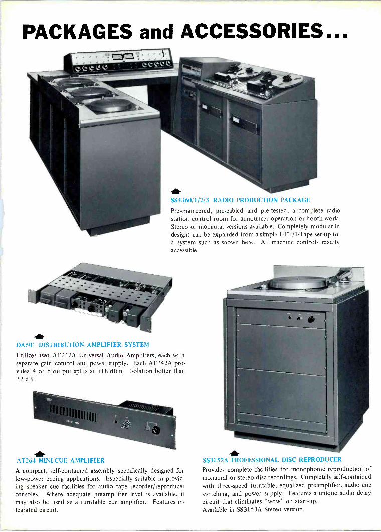
SS4360/1/2/3 RADIO PRODUCTION PACKAGE
Pre-engineered, pre -cabled and pre -tested, a complete radio station control room for announcer operation or booth work. Stereo or monaural versions available. Completely modular in
design: can be expanded from a simple 1-TT/1-Tape set-up to a system such as shown here. All machine controls readily accessible.
DÁ501 DISTRIBUTION AMPLIFIER SYSTEM
Utilizes two AT242A Universal Audio Amplifiers, each with separate gain control and power supply. Each AT242A pro- vides 4 or 8 output splits at +18 dBm. Isolation better than 32 dB.
er- AT264 MINI -CUE AMPLIFIER
A compact, self-contained assembly specifically designed for low -power cueing applications. Especially suitable in provid- ing speaker cue facilities for audio tape recorder/reproducer consoles. Where adequate preamplifier level is available, it
may also be used as a turntable cue amplifier. Features in- tegrated circuit.
SS3152A PROFESSIONAL DISC REPRODUCER
Provides complete facilities for monophonic reproduction of monaural or stereo disc recordings. Completely self-contained with three -speed turntable, equalized preamplifier, audio cue
switching, and power supply. Features a unique audio delay
circuit that eliminates "wow" on start-up. Available in SS3153A Stereo version.
LSA608 and LSA609 SPEAKER/AMPLIFIER ASSEMBLIES
Two 10 -watt speaker/amplifier assemblies ideal for monitoring applications. LSA608 is made for desk -top mounting; LSA609 has 15° reverse slope and is designed for wall -mounting.
COMPONENTS ... AT242A UNIVERSAL AUDIO AMPLIFIER One -watt output capability plus high gain and extremely low input noise permit the AT242A to be used for low-level micro- phone mixing, intermediate booster, or program output amp- lifier applications. Ideal for use as a distribution amplifier, such as applied in the McCurdy DA501 and DA502. Gain strappable incrementally between 50 and 64 dB. Optional remote gain available.
AM408A SOLID-STATE IOW MONITOR AMPLIFIER Self-contained, silicon solid-state unit delivers 10 watts con- tinuous sine -wave power over full audio spectrum with less than 0.5% harmonic or intermodulation distortion. Immune to overdrive and short-circuit failure. Remote gain control is optional.
EQ150 VARIABLE EQUALIZER One equalizer provides variable equalization in precise steps: 40 Hz, 100Hz, 3, 6, 10 & 15 kHz all in a single package. In -Out switch allows presetting for desired effect. Presence boost equalization included.

modular mono production console

standard equipment &options
The McCurdy SS8400 mono console is a fully modular, professional audio mixing unit. Standard features with available, additional options fulfill the most exacting requirements for 'On Air' use in AM radio facilities. The SS8400 console's capabilities provide the nucleus for total Broadcast Production Packages.
Quality Features of the Series 8000 Module
a) Integrated circuit technology b) Balanced input and output stages c) Provision for insertion of "Audio Processing
Equipment"- equalizers, compressor/limiters, etc.
d) SILENT! "Momentary Action" pushbutton for "channel -on" switching
e) Front panel plug-in capability f) Complete compatability with other modules in
the 8000 series, with available options suited to specific requirements
Standard Equipment on the SS8400 Mono Console 12 input mixing channels, complete with A/B switching, allowing for 24 audio sources.
Each mixer equipped with specially designed "conductive plastic" slide attenuator (fader).
Cue switching provided with fader in maximum attenuator position, and front panel pushbutton to facilitate production procedures. Output from each input mixer is available to either program channel or both simultaneously. Input sensitivity switching (2 position), to suit specific mix requirements. Customer choice at time of purchase. 2 identical program output channels, each equipped with "channel -on" switching, rotary gain controls and VU meters. 2 monitor preamplifier and control systems, complete with 8 input selections.
One cue/talkback system allowing 3 -station communication. Extender module.
Available Options for the SS8400 Mono Console
Provision is made for the insertion of:
1) Machine remote control modules 2) EQ 155 equalizers 3) CP 159 compressor 4) OT 157 multi -frequency oscillator 5) Foldback system 6) Echo -send and return 7) `Solo' monitor feature 8) Real-time digital clock SA138A
9) Elapsed -time digital counter and control panel SA137A
10) Distribution amplifier systems
Sensible Styling The SS8400 mono console is housed within a one- piece welded steel enclosure for maximum shielding in high RF environments. Completely free-standing, self-supporting console. Control panel hinges upward to facilitate service and routine test procedures. Console end bells and VU meter housing are richly toned, hand -rubbed, oiled walnut. Woodgrain finish on control panel surface, high- lighted with engraved style strips. Padded armrest adds to both the appearance and operating comfort of the console.
Ease of operation is assured with controls arranged in easily accessible, uncrowded groupings for related functions.
0c >U0
PON
CH
-p
LINE
O 0 41) -FO-
0 CUE
HUD
ROM
CX
IM 8401-00 -02 IM 8408-00-06

facilities & options
Series 8400 Mixer Module Options
OPTIONS 8401 8402 8403 8404 8405 8406 8407 8408 8409 8401-01 8402-01 8408-01 8409-01
02 0 0 0 O O O 03 O O 04 0 0 05 0 O 06 0 0 0 0 0 0 0 07 0 O O O O O O
CHANNEL ON O O O O O O O O O O O O O PROGRAM O O O O O O O O O AUDITION O O O O O O O O O CUE O O O O O O O O O O O O O SOLO O O O O O ECHO SEND O O O O O 0 FOLOBACK O O O O O
Series 8400 Input Options
O CUE
FOEOeeu
OFF
MIC.
02
A B OFF
8
-6oí/ \F
A B OFF 0+ 0
60
MIC./LINE MIC./LINE
Series 8400 Output & Auxiliary Modules
O CUE
0
OPOT
O E.T 2
O "T O CUE
onO
o
60 20
MIC. / LINE
05
oe 00 06 o6 04 o3 02 oI
-20
B
e e
20
mow. LINE
PROGRAM
MASTER
0
06
PROGRAM
LEFT
MASTER
E FM 8446 EM 8446 EFM 8446 CM 8441 MM 8431 PM 8421 PM 8521
(BONO) IMONO) (MOH01 (MONO) AUE 8421 AUD 8521
FOLDBACN ECHO SEND F13/ES TALNBACN/CUE
(008m OUT, (04.00T)
MASTER MASTER MASTER MODULE PM 8423
AUD 8423 MONITOR MODULE (.9)1B). art)
LINE
07
PM 8422
AUD 8422
PROGRAM /AUDITION 1
MODULES

installation
33" (838 mm.)
SS 8400 CONSOLE
TOP
30" (762 mm)
FRONT
34" (863 mm)
SOLID WALNUT END BELL 8 V.U. COVER
HINGED PANEL q
II
II II
II II
II II
II
II
II
11
1
II
11
II II II II
11
II
S IDE
4"
(152 mm)
37" (939 mm)
McCurdy Radio Industries reserves the right without notice to make such changes in equipment, design, specifications, or components, as progress in engineering or manufacturing techniques may warrant, to improve the performance of the product.
Printed in Canada SS8400 Console/'Issue 2/12.76
McCurdy Radio Industries Limited, 108 Carnforth Road,Toronto, Ontario M4A 2L4 (416) 751-6262 Telex: 06-963533
McCurdy Radio Industries Incorporated, TWX: 610-492-3219 1051 Clinton Street, Buffalo, N.Y. 14206 (716) 854-6700 Telex: 06-963533
U.S.A. East Coast Office, Saddle River, N.J. P.O. Box 86, 07458 (201) 327-0750
SS8400 Mono Console
specifications
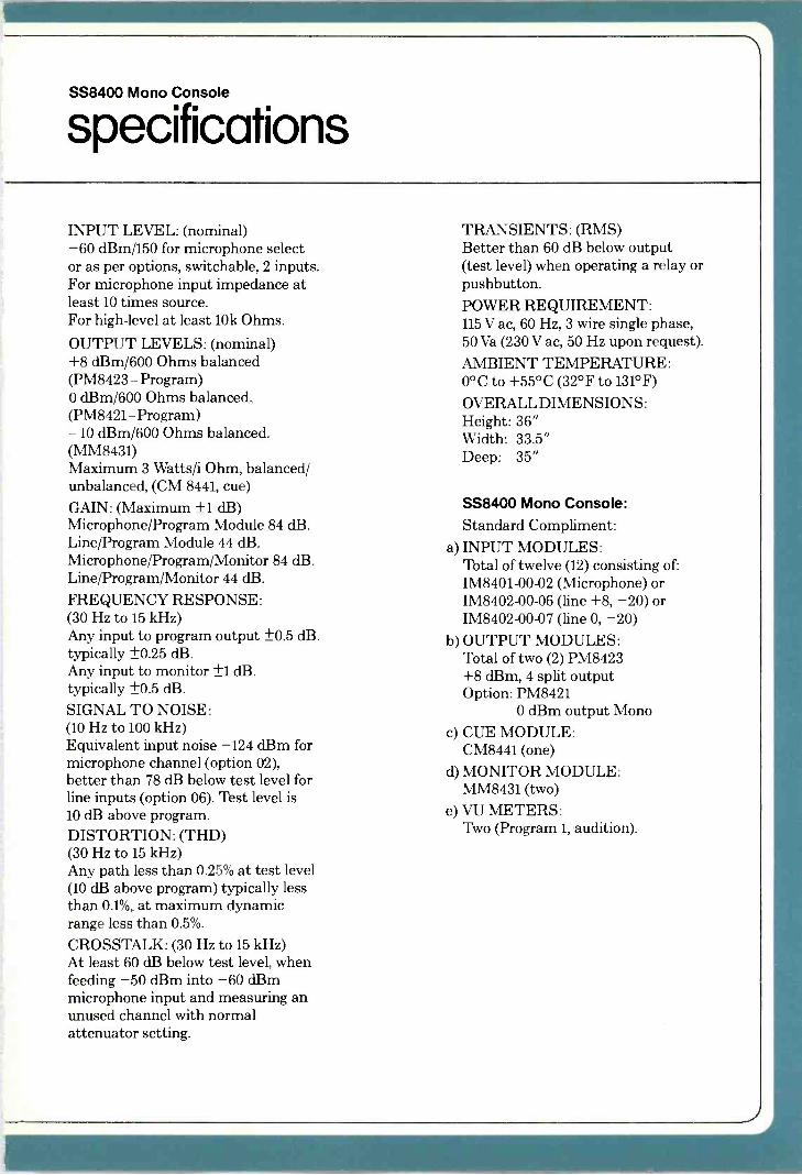
INPUT LEVEL: (nominal) -60 dBm/150 for microphone select or as per options, switchable, 2 inputs. For microphone input impedance at least 10 times source. For high-level at least 10k Ohms.
OUTPUT LEVELS: (nominal) +8 dBm/600 Ohms balanced (PM8423 - Program) 0 dBm/600 Ohms balanced. (PM8421-Program) -10 dBm/600 Ohms balanced. (MM8431) Maximum 3 Watts/i Ohm, balanced/ unbalanced, (CM 8441, cue)
GAIN: (Maximum ±1 dB) Microphone/Program Module 84 dB. Line/Program Module 44 dB. Microphone/Program/Monitor 84 dB. Line/Program/Monitor 44 dB.
FREQUENCY RESPONSE: (30 Hz to 15 kHz) Any input to program output ±0.5 dB. typically ±0.25 dB. Any input to monitor ±1 dB. typically ±0.5 dB.
SIGNAL TO NOISE: (10 Hz to 100 kHz) Equivalent input noise -124 dBm for microphone channel (option 02), better than 78 dB below test level for line inputs (option 06). Zést level is 10 dB above program. DISTORTION: (THD) (30 Hz to 15 kHz) Any path less than 0.25% at test level (10 dB above program) typically less than 0.1%, at maximum dynamic range less than 0.5%.
CROSSTALK: (30 Hz to 15 kHz) At least 60 dB below test level, when feeding -50 dBm into -60 dBm microphone input and measuring an unused channel with normal attenuator setting.
TRANSIENTS: (RMS) Better than 60 dB below output (test level) when operating a relay or pushbutton. POWER REQUIREMENT: 115 V ac, 60 Hz, 3 wire single phase, 50 Va (230 V ac, 50 Hz upon request).
AMBIENT TEMPERATURE: 0°C to +55°C (32°F to 131°F)
OVERALL DIMENSIONS: Height: 36" Width: 33.5" Deep: 35"
SS8400 Mono Console: Standard Compliment:
a) INPUT MODULES: Total of twelve (12) consisting of: IM8401-00-02 (Microphone) or IM8402-00-06 (line +8, -20) or IM8402-00-07 (line 0, -20)
b) OUTPUT MODULES: Total of two (2) PM8423 +8 dBm, 4 split output Option: PM8421
0 dBm output Mono
c) CUE MODULE: CM8441 (one)
d) MONITOR MODULE: MM8431 (two)
e) VU METERS: Two (Program 1, audition).
_}

r ---A - c- ---, r --- e
L
o
o
L___
: z J L_
A
s i
1
a <
____J L
b
2
$1
o
DO
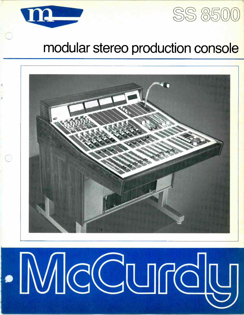
modular stereo production console
o
description The McCurdy SS8500 stereo console is a fully modular, free-standing audio production and mixing system providing full facilities for broadcast or other professional applications. Its compactness and flexibility make it ideally suited for use as an `on -air'
console or master control centre in radio facilities. The wide range of modules available along with the many options allow custom tailoring of the console to suit your individual needs.
SS8500 package features Fully modular, all modules, amplifiers, controls, power supplies and optional equipment plug-in to the console panel or auxiliary frames for ease of maintenance. All units employ the latest technology in reliable silicon solid-state circuitry. The console housing is a one-piece enclosure fabricated of all -welded heavy -gauge steel for strength and maximum RF shielding. It is finished in
scratch -resistant, textured blue baked enamel. The control panel hinges upward, aided and damped by high-pressure gas cylinders, allowing access to all internal wiring. Free standing, completely self-supporting unit, no table or desks required. The console is stable even with control panel lifted.
The console control panel is finished in
damage -resistant woodgrained vinyl clad steel inset into etched, extruded aluminum panels and high -lighted by engraved style strips. A padded armrest covered in durable black leather - grained vinyl is provided for operating comfort. The console end bells and VU housing are constructed of richly grained hand -rubbed oiled walnut. For ease of operation, all controls are easily accessible and arranged in uncrowded groupings according to related functions. All input/output connections are made to terminal blocks or to connectors, XLR type for audio, rack and panel type for DC controls, mounted on a hinged panel.

SS8500 operational facilities Ten stereo input channels are provided, complete with A/B switching, allowing for 20 stereo audio sources. Each mixer is equipped with a specially designed Penny and Giles conductive plastic stereo slide attenuator with greater than 80 dB attenuation before cutoff, excellent stereo tracking and separation. Cue switching is provided in the maximum attenuation position of each attenuator along with a front panel pushbutton on each input, echo send or foldback module. Illuminated Program and Audition selector pushbuttons are provided on each input module to allow operation to both output channels simultaneously or each independently. Two stereo output channels, Program and Audition, are provided. Each is supplied with four output splits, with up to 12 available on each. Four VU meters are provided, two each for the Program and Audition outputs. Provision is made for a mono output channel and metering. A wide range of standard input modules is available providing complete facilities and allowing the tailoring of each mixer input to suit your specific requirements. Certain input modules are equipped with a pan control to enable panning of the single (mono) input between the two (stereo) module output channels. All inputs are balanced, with provision for accommodating levels from -70 dBm to +10 dBm across the range of input modules. Channel on/off switching controlled by an illuminated, silent, momentary pushbutton switch. Provision is made for remote channel -on switching by a single on/off switch or separate on and off switches.
Complete monitor facilities, incorporating an eight pushbutton selector and rotary gain control, are provided. Separate monitor facilities with individual input selection and rotary gain control can be supplied for control room, headset or other requirements. Cue monitor is provided by a pushbutton on each input module or from the maximum attenuation position of each mixer attenuator. All microphone inputs are balanced and floating. All line inputs are balanced and bridging. All outputs are active, balanced. Provision is made for the insertion of optional signal processing equipment, such as equalizers, compressors, filters, etc. Echo Send and Foldback outputs, complete with gain controls, VU meters selector and on/off switches, are available. These features are prewired, requiring only the addition of the amplifier modules and metering panel. Output amplifier modules can be supplied with internal rotary gain controls or external slide attenuators. A comprehensive cue/talkback system, complete with microphone and speaker, is provided to allow complete four station inter -communication. Talkback is mixed with cue, preventing loss of cue during inter -communication. Plug-in modules for remote, DC, control of tape machines, turntables, etc. are available. Up to five illuminated, silent, momentary pushbuttons per module can be supplied. Plug-in modules for input selection, providing ten select pushbuttons, and mode selection are available. The direct microphone channel output can be optionally utilized to allow the announce microphone to be used with external equipment, intercom, etc. Fully customized versions of this console can be designed to suit your particular system requirements.
3
available options
Remote control modules, up to 5 pushbutton, for tape machines, etc. Equalizers and equalizer delegation Compressors Multi -frequency oscillators Foldback system Echo -send and return system Real time digital clock with internal battery to prevent loss of time during power failures and capability to drive four remote displays Digital up/down counter with control panel capable of driving four remote displays and remote control from machine starts Distribution amplifier systems Ten station input selectors
Stereo mode selectors Monitor power amplifiers Mono output channel and VU meter Peak program meters Prewired jackfields Redundant power supply systems with automatic or manual changeover Additional output splits, up to a maximum of 12 per output Direct, unswitched, microphone outputs Operation on 220-240V AC Power
4
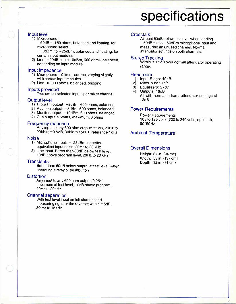
Input level 1) Microphone:
-60dBm, 150 ohms, balanced and floating, for microphone select -70dBm, to -25dBm, balanced and floating, for certain input modules
2) Line: -20dBm to +10dBm, 600 ohms, balanced, depending on input module
Input impedance 1) Microphone: 10 times source, varying slightly
with certain input modules 2) Line: 10,000 ohms, balanced, bridging
Inputs provided Two switch -selected inputs per mixer channel
Output level 1) Program output: +8dBm, 600 ohms, balanced 2) Audition output: +8dBm, 600 ohms, balanced 3) Monitor output: -10dBm, 600 ohms, balanced 4) Cue output: 2 Watts, maximum, 8 ohms
Frequency response Any input to any 600 ohm output: ±1 dB, 20Hz to 20kHz; ±0.5dB, 30Hz to 15kHz, reference 1 kHz
Noise 1) Microphone input: -125dBm, or better,
equivalent input noise, 20Hz to 20 kHz 2) Line input: Better than 80dB below test level,
10dB above program level, 20Hz to 20 kHz
Transients Better than 60dB below output, at test level, when operating a relay or pushbutton
Distortion Any input to any 600 ohm output: 0.25% maximum at test level, 10dB above program, 20Hz to 20kHz.
Channel separation With test level input on left channel and measuring right, or the reverse; within ±5dB, 30 Hz to 15kHz
Crosstalk At least 60dB below test level when feeding -50dBm into -60dBm microphone input and measuring an unused channel. Normal attenuator settings on both channels.
Stereo Tracking Within ±0.5dB over normal attenuator operating range.
Headroom 1) Input Stage: 40dB 2) Mixer bus: 27dB 3) Equalizers: 27dB 4) Outputs: 16dB
All with normal in -hand attenuator settings of 12dB
Power Requirements Power Requirements 105 to 125 volts (220 to 240 volts, optional), 50/60Hz
Ambient Temperature 0° to 55°C(76° to 131°F)
Overall Dimensions Height: 36 in. (91.44 cm) Width: 33.5 in. (85.1 cm) Depth: 35 in. (88.9 cm)
5
ordering information Contact the nearest McCurdy Radio office for engineering assistance, application and pricing information.
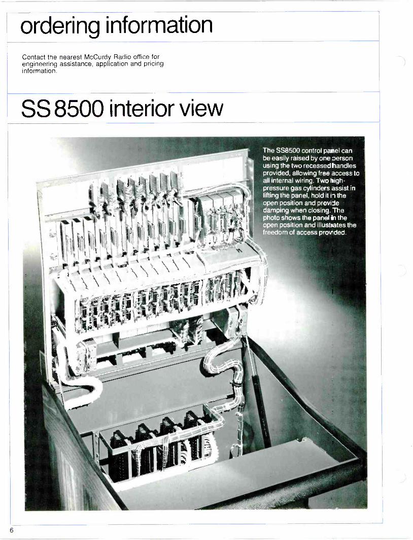
SS 8500 interior view
The SS8500 control panel can be easily raised by one person using the two recessed handles provided, allowing free access to all internal wiring. Two high- pressure gas cylinders assist in lifting the panel, hold it ii the open position and provide damping when closing. The photo shows the panel in the open position and illustrates the freedom of access prou ded.

SS8500 series output modules
Right Channel Gain Control Adjusts Gain of Right Channel
LEFT
RIGHT
MASTER
Left Channel Gain Control Adjusts Gain of Left Channel
Channel -On Switch Connects Module Output to Output Line
PM8521 - PROGRAM OUTPUT AUD8521 - AUDITION OUTPUT
The Channel -On Switches are Illuminated, Alternate -
Action Pushbuttons. On when depressed
Gain of These Modules Is Adjusted By An External Slide Attenuator
MASTER
Channel -On Switch Connects Module Output To Output Line
PM8522 - PROGRAM OUTPUT AUD8522 - AUDITION OUTPUT
7

TYPICAL STEREO INPUT
Echo Send On/Off Switch connects module output to
echo send bus
Foldback On/Off Switch connects module output to
foldback bus
Cue On/Off Switch Connects pre -fader
output to cue bus
Program Assign Switch connects module output to
program bus
Channel -On Switching may also be controlled remotely on any module
LINE
k_ ES
L__ FB
CUE
AUD
IM8508-00-09
Input Selector Selects Off, A or B input and on some modules, Level
Echo Send Level Control adjusts level of Echo Send output
Foldback Level Control adjusts level of foldback output
Audition Assign Switch connects Module output to Audition bus
Channel -On Switch connects module output to input of other Assign switches
TYPICAL MONO INPUT
Input Select Switch selects A input, Off, or
B input
Echo Send On/Off Switch connects module output
to echo send bus
-40 -55 i-20
5 Input Sensitivity Switch - selects desired input level
B
INPUT
Cue On/Off Switch- connects pre -fader
output to cue bus
Program Assign Switch connects module output
to program bus
-Gain Trim Control allows input sensitivity to be
°TRI M15 decreased up to 15dB
L Es _I CUE PAN
AUD
Echo Send Level Control Adjusts level of echo send output
Pan Control Allows panning of the mono input between the left & right
Noutputs
IM8508-00-07
Audition Assign Switch Connects module output to audition bus
Channel -On Switch Connects module output to input of other assign switches
Audition, Program and Channel -On switches are illuminated
OfF
A I B
MIC
CUE
I AUD I
PGM
1
G
A B OFF
-60 I 48
MtC/LINE
CUE
DUD
PGM
1
1M8501-00-02 1M8501-00-08
A B OFF
-60 +8
MIC/LINE
L- ES
T I-- F8
CUE
AUD
0 IM8507-00-08
A
LINE
* Es
FB
CUE
AUD
PGM
IM8508-00-06
8

SS8500 series input modules
A OFF 8
[18+741 20
0 20
LINE
CUE
AUD
IM8502-00-06
A OfF B
Flo O I
m
o LINE * Es __I * F8
CUE
AUD
PGM
1M8508-00-07
A OFF B
Po j-1 20 0 20
LINE
CUE
[.:LE,
OFF
A A
\ /
HIC
LESJ
CUE
I AUD
PGM
J
!CHI
I M8502-00-07 I M8505-00-02
A OFF 9
A +1-81 0
LINE
ES
L-F8
CUE
AUD
PUM
OFF
A I 8
MIC
CUE PAN
OUA
ACM
1
A B OFF
-60 I +8
\ /
MIC/LINE
* LES ---i
CUE
I AUD
I
PGM I
IM8505-00-08
MIC/LINE
CUE PAN
YG
I APO 1
PGM
1
fl
1M8508-00-09 1M8509-00-02 1M8509-00-08
A OFF B
P8 +71 20 o
LINE
LESJ
CUE
AUD
PGM
LINE
JES
CUE
IM8506-00-06 1M8506-00-07
OFF
A B
MIC
LESJ
CUE PAN
R AUD
M8510-00-02 (MONO INPUT) (MONO INPUT) (MONO INPUT)
A OFF B
-60 I +8
\/
MIC/LINE
ES J
CUE PAN
I AUD
m
-40 -55 -20
IB I
INPUT TRIM * LESJ
CUE PAN
LR AUD
m v
1M8510-00-08 M8511-00-10 (MONO INPUT) (MONO INPUT)
9

SS8500 series auxiliary modules
Left Channel Gain Control Adjusts gain of left channel output
Left Channel Cue On/Off Switch. Connects pre -gain control output to
cue bus
Left Channel -On Switch Connects left channel output to output
line
Right Channel Gain Control Adjusts gain of right channel output
Right Channel Cue On/Off Switch
Connects pre -gain control output to cue bus
Right Channel -On Switch Connects right channel output to
output line
Left Channel Gain Control Adjusts gain of left channel output
Left Channel Cue On/Off Switch Connects pre -gain control output to
cue bus
Left Channel -On Switch Connects left channel output to output
line
CUE
LEFT
-r
CUE
RIGHT
BOLDBACK
FFM 8446 STEREO FOLDBACK
CUE
LEFT
Right Channel Gain Control Adjusts gain of right channel output \ L
Right Channel Cue On/Off Switch N
Connects pre -gain control output to cue bus RIGHT
Right Channel -On Switch - Connects right channel output to
output line
CUE
um ECHO SEND
EEM 8446 STEREO ECHO SEND
TALKBACK
ST a
ST ' 3
ZT O ST .i`
WE LEVEL
CM 8442 4 STN CUE MODULE
8
GAIN
MM 8532 STEREO MONITOR
Talkback Call Switches Allows operator to call one of four stations
Talkback Indicators Illuminated when being called by designated station
Cue Level Control Adjusts level of output to cue speaker
Input Select Switches Selects one of eight inputs to be monitored
Designation Strip Indicates connections to input select switches. May be easily changed allowing customer designation of switches.
Monitor Gain Control Adjusts level of monitor output
All Channel -On Switches are illuminated, alternate action pushbuttons on when depressed
10

8500 series accessory modules
cm TERE
IS8554 STEREO MODE SELECTOR
Left input to left & right
Output Switch
Right input to left & right
Output Switch
Stereo Switch Switches are illuminated pushbuttons, on when depressed
0
DC8481 1 STN. MOM D.C. CTL
U
DC8481 L 1 STN. ALT/ACT D.C. CTL
10
ITuuul
IS8553 STEREO INPUT SELECTOR
DC8485 5 STN. MOM D.C. CTL
Input Select Switch Allows selection of 1 of 10 stereo inputs
Designation Strip Indicates connections to input select switches. May be easily changed allowing customer designation of switches.
I I
U
DC8482 2 STN. MOM D.C. CTL
U 8
DC8483 3 STN. MOM D.C. CTL
n O
DC8484 2 STN. MOM D.C. CTL
D.C. Remote Controls 1, 2, 3 or 5 illuminated pushbutton switches for remote control functions
11

INPUT MODULE
e
INPUT MODULE
INPUT MODULE
AUD
PGM L
AUD R
PGM R
EIS L
E/S R
F/B L F/B R
CUE
12

SS8500 functional
7" V '9Y PGM MODULE PM8521
V 7" V AUDITION MODULE AUD8521
r 1 1 s. 4 j-\
-T r-----tx++r-----, r------>- 1 I,. I 1
NI n ,t 1 \. { I :1~----1q r----1 ----ÿ
L VE/S MODULE EEM8446 L Y
r - ----}} ----I Rti¡ r1 ept
V.1 I I
î\ ,\ I - ----ar---- ÿ) 4- 1
L_ F/8 MODULE FFM8446 J oc)
PGM VU LEFT
PGM VU RIGHT
AUD VU LEFT
AUD VU RIGHT
r ECHO SEND
r-- A,. I
L__J
r7.7.1
E/S VU LEFT
I E/S VU RIGHT L__J
r-- F/B VU LEFT
FOLDBACK
L__J
r--1 r -4 ` I
L _J F/B VU RIGHT
8 0R 7 6 5 EXT 5 EXT 4 EXT 3 EXT 2
C.R. MONITOR MODULE MM8532
i 4 3 2
EXT I AUD PGM
4"12 D
IOR -MV- 1 OFF /
PARALLEL TO C.R. MONITOR
, , 8 0R 7 6
EXT 5 EXT 4 EXT 3
HDST. MODULE MM8532
5 EXT 2
4 EXT I AUD PGM OFF
I ; + I OR "
^I 1/Vv
0
1
>--114->
CUE MODULE CM8442
2
3
4
HM7473
T/B TO B FROM
[c
VW
CUE SPEAKER
SS8500
C.R. MONITOR
HOST. MONITOR
13

Program & Audition VU Meters
Digital Clock or Up/Down Counter (Optional)
Fixed Equalizers In Mono Input Channels Only
Input Modules, 10 Channels, Stereo
Specially Designed Conductive Plastic Slide Attenuators
for 10 Input Channels
Recessed Lifting Handle For Lifting Control Panel
DC Remote Controls
Solid Walnut End Bells
All Blank Panels, with the exception of those at outer edges, may be utilized for optional or future equipment.
r-/ r\- f' ;p ....,:...o-
f\.. ÌnL_i p . -
u. :J ,7---
P-- .... .. .. " 0
%'
.1\-
f\ i \ ::e
J t avt 15 10
r\ ,1 - o
\
^5dkb J Ce OA
wlao
fOWAu
OO Le ON
[0 IMO
\ A A \ \ /\ / \ /-, n ./-,,./-,, A,
,--,,, 7\ .7---
(;).(I
1;
- *
0000
I
-
O 0
,
[" H
.
..
,
r U [l H
Y.
I 1 ' '
I 1 i 1
H LI
7-\
i / i'-- \ \ : / / -.
o
S
10
ü
J0
0
S
NIS 20
o
70
o
5
10
o
10
00
e
O
00
o
10
20
0
01
20
\ 0
lU
0
11
]0
---\ 0
20
0
M
00
0
10
K
20
\ 0
R
M
\ i--\.
Os
L
10
IS
50
10=J0 á5=ai5
25
30
25
10
S
. SO
15
Jc
)5
10
15
50
ID=JO 5ú=
is
l0
15
10
IS
50
ai
25
20
%
!
50
aiw5
25
00
25
IC
. 50 0 7 JS
20
7S
10
45 SO
ID =JO óE=ais
25
20
25
IU
15
M
ri
lY
JS
10
16
50
ID=ID ú=
ri
)0
25
M 15 50
ai
ri
20
l5
10
15
50
JO =O ñ.tóE
25
20
25
M If
Y
25
20
OS
10
IS SO
JO
á5=cú
25
JO
25
10
45 SO
ID
gH ,,..__,
SOME OF THE FACILITIES & EQUIPMENT ILLUSTRATED IS OPTIONAL, AT EXTRA COST. .
14
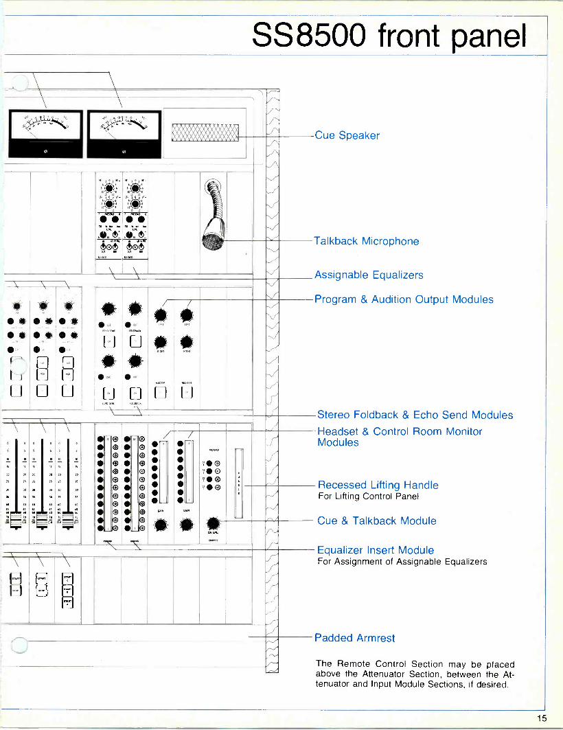
SS8500 front panel
9 11..1/ .................
.,
tiu,u,v
ti ;
ve,
ie ^;
s. ' TVIErT
. eíodti+
Ilk
me é \ \
1
Me We
H
...
.
eIX0YC5 ii . a
/ , le.
/
0 0 a
15
00 20 20
25 }s 05
30 30 00 eo
OS
40
éó
70 70 w
L 5.111
-
,- f ./`
lr
11_2_ GAIN
Cue Speaker
Talkback Microphone
Assignable Equalizers
H
Program & Audition Output Modules
Stereo Foldback & Echo Send Modules
Headset & Control Room Monitor Modules
Recessed Lifting Handle For Lifting Control Panel
Cue & Talkback Module
Equalizer Insert Module For Assignment of Assignable Equalizers
Padded Armrest
The Remote Control Section may be placed above the Attenuator Section, between the At- tenuator and Input Module Sections, if desired.
15

installation
f 33"
(836 mm.)
TOP
FRONT
v
30" (762 mm)
(863 mm)
SOLID WALNUT END BELL 8 V.U. COVER
HINGED PANEL
/,,
i /
ll
34" 4
il
i ii
SIDE
4" (152 mm)
37" (939 mm)
PRINTED IN CANADA
Th
McCURDY RADIO INDUSTRIES LIMITED 108 CARNFORTH ROAD. TORONTO. ONTARIO M4A R4 (416)751-6262, TELEX 06.963533, TWX 610-492-1373
McCURDY RADIO INDUSTRIES INC. UNITED STATES HEAD OFFICE
1711 CARMEN DRIVE, ELK GROVE VILLAGE, IL_ NJIS 60007, (312) 640.7077, TWX 910-222-0436
EAST COAST OFFICE
223 WEST SADDLE RIVER ROAD, SADDLE RIVER, N.J. 07458, (201) 327-0750, TWX 710-988-2254
BUFFALO WAREHOUSE
1051 CLINTON STREET, BUFFALO, N.Y. 14206, DIFECT LINE TO TORONTO PLANT (716)854-6700, TWX 610-492-1373
McCurdy Radio Industries reserves the right, without notice to make suchchanges in equipment, design, specifications, or components as progress in engineering or manufacturing techniques may warrant to improve the performance of the product.

0
modular stereo audio console
eAcCuffi o

description The McCurdy SS8650 stereo console is a fully modular, free-standing audio production and mixing system providing full facilities for broadcast or other professional applications. Its compactness and flexibility make it
ideally suited for use as an "on -air" console or master control centre in radio facilities.
Each SS8650 is built with the full range of popular options prewired, allowing them to be supplied by merely inserting the proper modules into the spaces and connectors provided. Thus, permitting a high quality full feature console to be made available at a very reasonable price. A limited number of special order options are also available. These features along with the comprehensive range of modules available allow tailoring of the console to suit your specific requirements.
The SS8550 console, offering many of the same features as the SS8650, with fewer mixers and in a smaller package, is available for installations where space is at a
premium.
The SS8500 and SS8600 series consoles are available for installations requiring more operational facilities, equalizers in each channel, mode selectors, etc., than are incorporated in the SS8650.
SS 8650 package features Fully modular, all modules, amplifiers, controls, power supplies and optional equipment plug-in to the console panel or auxiliary frames for ease of maintenance. All units employ the latest technology in reliable silicon solid-state circuitry. The control panel hinges upward, aided and damped fabricated of all -welded heavy -gauge steel for strength and maximum RF shielding. It is finished in scratch - resistant, textured blue baked enamel. The control panel hinges upward, aided and dampened by high-pressure gas cylinders, allowing access to all internal wiring. Free standing, completely self-supporting unit, no table or desks required. The console is stable even with control panel lifted. The console control panel is finished in damage - resistant woodgrained vinyl clad steel inset into etched, extruded aluminum panels and highlighted by engraved style stripe.
A padded armrest covered in durable black leather - grained vinyl is provided for operating comfort. The console end bells and VU housing are constructed of richly grained hand -rubbed oiled walnut. For ease of operation, all controls are easily accessible and arranged in uncrowded groupings according to related functions. All input/output connections are made to telephone type terminal blocks easily accessible from the rear of the console. A large, centrally located script board is provided for operating convenience.
SS 8650 operational facilities A maximum of sixteen stereo input channels are provided, complete with A/B switching, allowing for 32 stereo audio sources. Each mixer is equipped with a specially designed Penny and Giles conductive plastic stereo slide attenuator with greater than 80dB attenuation before cutoff, excellent stereo tracking and separation. Cue switching is provided in the maximum attenuation position of each attenuator along with a front panel pushbutton on each input, echo send or foldback module. Illuminated Program and Audition selector pushbuttons are provided on each input module to allow operation to both output channels simultaneously or each independently. A maximum of two stereo output channels, Program and Audition, are provided. Each is supplied with four output splits. Two VU meters are provided for the program output. Provision is made for a mono output channel and metering. A wide range of standard input modules is available providing complete facilities and allowing the tailoring of each mixer input to suit your specific requirements. Certain input modules are equipped with a pan control to enable panning of the single (mono) input between the two (stereo) module output channels. All inputs are balanced, with provision for accommodating levels from - 70dBm to + 10 dBm across the range of input modules. Channel on/off switching controlled by an illuminated, silent, momentary pushbutton switch.
Provision is made for remote channel -on switching by a single on/off switch or separate on and off switches. Complete monitor facilities, incorporating two modules, each provided with an eight pushbutton selector and rotary gain control. Separate monitor facilities with individual input selection and rotary gain control can be supplied for control room, headset or other requirements. Cue monitor is provided by a pushbutton on each input module or from the maximum attenuation position of each mixer attenuator. All microphone inputs are balanced and floating. All line inputs are balanced and bridging. All outputs are active, balanced. Provision is made for the insertion of optional, balanced, signal processing equipment, such as equalizers and compressors. Echo Send and Foldback outputs, complete with gain controls, VU meters selector and on/off switches, are available. Output amplifier modules are supplied with internal rotary gain controls. A comprehensive cue/talkback system, complete with built-in speaker, is provided to allow complete four station inter -communication. Talkback is mixed with cue, preventing loss of cue during inter -communication. Plug-in modules for remote, DC, control of tape machines, turntables, etc. are available. Up to five illuminated, silent, momentary pushbuttons per module can be supplied. Plug-in modules for input selection, providing ten select pushbuttons, and mode selection are available.

available options Prewired Options:
The following options are prewired on all SS8650 consoles, allowing them to be supplied by merely inserting the proper modules into the spaces and connectors provided.
Audition output channel with four 600 ohm splits and rotary level controls. Talkback microphone. Two variable equalizers and equalizer insert modules equipped with twelve -position pushbutton switches incorporating integral indicators. Equalizer insert module also available with red LED indicators. Stereo or mono Echo Send and Foldback outputs. Two VU meters for Audition output channel. Audition VU meter select switch, when equipped with Audition VU meters, allowing selection of Audition, Echo Send, Foldback or one of two external inputs for VU monitoring. Mono sum output. VU meter for monitoring of mono sum output. Selector switch allowing the mono sum output to be taken from either the Program or Audition output. Peak Program Meters in place of any or all of the VU meters. A maximum of two, ten -station stereo input selectors. One multi -frequency precision test oscillator for console set-up, testing, etc. An enclosed auxiliary frame assembly, mounting beneath the main console housing, for installation of distribution amplifiers, monitor amplifiers, or other special equipment. One additional monitor module, with eight -station selector and rotary gain control.
Special Order Options: The following options are supplied on special order only, they are not prewired and must be specified at time of ordering.
A maximum of twenty-two DC remote control modules for the control of turntables, tape machines or other external equipment from the console control panel. Distribution amplifier systems. Monitor power amplifiers. Prewired jackfields. Redundant power supply systems with automatic or manual changeover. Direct, unswitched microphone outputs. Real time digital clock with internal battery to prevent loss of time during power failures and capability to drive four remote displays. Digital up/down counter with control panel, capable of driving four remote displays and remote control from machine starts. Placement of remote control section above attenuator section, between attenuator and input module section. Input/output connections made to connectors, XLR type for audio, rack and panel type for DC controls, instead of terminal blocks. All are mounted on a hinged rear panel. Operation on 220 to 240 Volt AC power.
4
specifications Input level
1) Microphone: -60dBm, 150 ohms, balanced and floating, for microphone select -70dBm, to -25dBm, balanced and floating, for certain input modules
2) Line: -20dBm to +10dBm, 600 ohms, balanced, depending on input module
Input impedance 1) Microphone: 10 times source, varying slightly
with certain input modules 2) Line: 10,000 ohms, balanced, bridging
Inputs provided Two switch -selected inputs per mixer channel
Output level 1) Program output: +8dBm, 600 ohms, balanced 2) Audition output: +8dBm, 600 ohms, balanced 3) Monitor output: -10dBm, 600 ohms, balanced 4) Cue output: 2 Watts, maximum, 8 ohms
Frequency response Any input to any 600 ohm output: ±1 dB, 20Hz to 20kHz; ±0.5dB, 30Hz to 15kHz, reference 1 kHz
Noise 1) Microphone input: -125dBm, or better,
equivalent input noise, 20Hz to 20 kHz 2) Line input: Better than 80dB below test level,
10dB above program level, 20Hz to 20 kHz
Transients Better than 60dB below output, at test level, when operating a relay or pushbutton
Distortion Any input to any 600 ohm output: 0.25% maximum at test level, 10dB above program, 20Hz to 20kHz.
Channel separation With test level input on left channel and measuring right, or the reverse; within ±5dB, 30 Hz to 15kHz
Crosstalk At least 60dB below test level when feeding -50dBm into -60dBm microphone input and measuring an unused channel. Normal attenuator settings on both channels.
Stereo Tracking Within ±0.5dB over normal attenuator operating range.
Headroom 1) Input Stage: 40dB 2) Mixer bus: 27dB 3) Equalizers: 27dB 4) Outputs: 16dB
All with normal in -hand attenuator settings of 12dB
Power Requirements Power Requirements 105 to 125 volts (220 to 240 volts, optional), 50/60Hz
Ambient Temperature
Overall Dimensions Height: 37 in. (94 mc) Width: 53 in. (137 cm) Depth: 32 in. (81 cm)
5

ordering information Contact the nearest McCurdy Radio office for engineering assistance, application and pricing information.
SS 8650 interior view
The SS8650 control canel can be easily raised by are person using the two recessed handles provided, allowing free access to all internal wiring. Two high- pressure gas cylinders assist in liftirg the panel, holc t in the open position and provide damping when closing. The photo shows the paiel in the open position and illustrates the freedom of access provided.
SS 8650 Similar to SS 8500 shown.
6

SS 8650 output modules
Right Channel Gain Control Adjusts Gain of Right Channel
Left Channel Gain Control Adjusts Gain of Left Channel
Channel -On Switch Connects Module Output to Output Line
PM8521 - PROGRAM OUTPUT, STEREO AUD8521 - AUDITION OUTPUT, STEREO
The Channel -On Switches are Illuminated, Alternate -
Action Pushbuttons. On when depressed
Gain Control Adjusts Gain
GAIN
MASTER
Channel -On Switch Connects Module Output To Output Line
PM8423-PROGRAM OUTPUT, MONO

TYPICAL STEREO INPUT
Echo Send On/Off Switch connects module output to
echo send bus
Foldback On/Off Switch connects module output to
foldback bus
Cue On/Off Switch Connects pre -fader
output to cue bus
Program Assign Switch connects module output to
program bus
Channel -On Switching may also be controlled remotely on any module
LINE
I- ES
FG
CUE
AUD
PGM
o
1M8508-00-09
Input Selector Selects Off, A or B input and on some modules, Level
Echo Send Level Control adjusts level of Echo Send output
Foldback Level Control adjusts level of foldback output
Audition Assign Switch connects Module output to Audition bus
Channel -On Switch connects module output to input of other Assign switches
TYPICAL MONO INPUT
Input Select Switch selects A input, Off, or
B input
Echo Send On/Off Switch connects module output
to echo send bus
-40 -55 -20
-70
A I B
INPUT - Cue On/Off Switch-
connects pre -fader output to cue bus
Program Assign Switch connects module output
to program bus
Input Sensitivity Switch selects desired input level
-Gain Trim Control allows input sensitivity to be
°TRIM15 decreased up to 15dB
LEsJ CIE PAN
AUD
m
1M8511-00-10
Echo Send Level Control Adjusts level of echo send output
Pan Control Allows panning of the mono input between the left & right outputs
Audition Assign Switch Connects module output to audition bus
Channel -On Switch Connects module output to input of other assign switches
OFF
A 8
/
MIC
CUE
AUD
l PUM
A B Off
-60 +8
/
Y MIC/LINE
CUE
I AO
PGM I
CH
1M8501-00-02 1M8501-00-08
A B Off
-60 +8
MIC/LINE
ESJ * LFg
CUE
AUD
A Ini
1 ,P ,y
LINE
* ESJ * FB
CUE
AUD
1M8507-00-08 1M8508-00-06
Audition, Program and Channel -On switches are illuminated
8

SS 8650 input modules
A Off B
p0 0 ?0 _
LINE
I M8502-00-06 I M8502-00-07
0 0
Q
*
a
.71 o o
I M8508-00-07 I M8508-00-09
OFF
A I B
/
MID
JESJ
CUE
AUD
H H
A 8 OFF
-60 I 48
MICE
J ES
CUE
I AUD
PGM
1
CH /
M8505-00-02 M8505-00-08
MIC
PA'.
() AUD
I I
-60 +8
11 MIC/LINE
CUI
IM8509-00-02 IM8509-00-08
A off B 8 ZO 20
LINE
- ES
CU,..
[AJO
J
PGM
A OFF B
Flo 1c71
o LINE
20
ES
I M8506-00-06 I M8506-00-07
CUE
4)111
PAN
AUD
I PGM
I
I M8510-00-02 (MONO INPUT) (MONO INPUT) (MONO INPUT)
A OFF 8
-60 I +8
MIC/LINE
CUE
ES
PAN
1 AUD
-40 -55 -20
7o -5
A I B
I /
INPUT 0 F15
TRIM
ES
CUE PAN
*EI NUB
1
I PGM
J
1M8510-00-08 1M8511-00-10 (MONO INPUT) (MONO INPUT)
9

SS 8650 auxiliary modules
Left Channel Gain Control Adjusts gain of left channel output
Left Channel Cue On/Off Switch Connects pre -gain control output to
cue bus
Left Channel -On Switch Connects left channel output to output
line
Right Channel Gain Control Adjusts gain of right channel output
CUE
LEFT
Right Channel Cue On/Off Switch CUE
Connects pre -gain control output to cue bus
Right Channel -On Switch Connects right channel output to
output line
RIGHT
EULDBACK
Mono Version Same As Shown FSTEREO 6
Except without left channel FOLDBACK
Left Channel Gain Control Adjusts gain of left channel output
Left Channel Cue On/Off Switch Connects pre -gain control output to
cue bus
Left Channel -On Switch Connects left channel output to output
line
Right Channel Gain Control Adjusts gain of right channel output
Right Channel Cue On/Off Switch
Connects pre -gain control output to cue bus
CUE
LEFT
CUE
Right Channel -On Switch- Connects right channel output to
output line
Mono Versions Same As Shown Except without right channel
RIGHT
ECHO SEND
EEM 8446 STEREO ECHO SEND
TALKEACK
ST a
SUI
, 3
SISO SAD E
CUE LEVEL
CM 8442 4 STN CUE MODULE
8
GAIN
MM 8532 STEREO MONITOR
Talkback Call Switches Allows operator to call one of four stations
Talkback Indicators Illuminated when being called by designated station
Cue Level Control Adjusts level of output to cue speaker
Input Select Switches Selects one of eight inputs to be monitored
Designation Strip Indicates connections to input select switches. May be easily changed allowing customer designation of switches.
:Monitor Gain Control Adjusts level of monitor output
All Channel -On Switches are illuminated, alternate action pushbuttons. On when depressed
0

SS 8650 accessory modules
12
08451
EQ8451 12 POSIT )N EQ INSERT
Equalizer Insert Selector állows selection of one of 12 equalizer insertion points
L.E.D. Indicators illuminated when corresponding insert select switch is depressed
Designation Strip indicates connections to equalizer insert select switches. May be easily changed allowing customer designation of switches
Also available EQ8454 12 position EQ insert same as EQ8451, except with self - indicating switches, and without LED indicators
n
DC8481 1 STN. MOM D.C. CTL
ri
DC8481 L 1 STN. ALT/ACT D.C. CTL
/Input Select Switch allows selection of one
S8553 STEREO INPUT SELECTOR
[7 O
DC8482 2 STN. MOM D.C. CTL
of 10 inputs
Designation Strip indicates connections to input select switches. May be easily changed allowing customer designation of switches
EEEL o
DC8485 5 STN. MOM IN/BLANK
DC8483 3 STN. MOM D.C. CTL
DC8484 2 STN. MOM D.C. CTL
D.C. REMOTE CONTROLS 1,2,3 OR 5 ILLUMINATED PUSHBUTTON SWITCHES FOR REMOTE CONTROL FUNCTIONS
11

T/ B
MIC
O
INPUT SELECTOR
CHANNEL I
O
O o
EO 8451
L
jo'41---(2-4>----4-11>---
INPUT MODULE
EO
8451 R ete
CHANNEL 10
O
O
INPUT MODULE
EO 8451
L
EO 8451
R
oeD
CHANNELS II- 16
INPUT MODUL-
AUD L
PGM L
AUD R
PGM R
E/S L
E/S R
F/B L
F/B R
CUE
CUE MODULE CM8442
HM7473
T/B TO B FROM
Q CUE SPEAKER
12

SS 8650 functional
PGM MODULE PM8521
-1>--NAH>.
AUD MODULE AUD8521
MONO SUM SELECT P
E08451
E08451 R
AUD
LE
E/S MODULE EEM8446
> F/B MODULE
E08451
>4) FFM8446
E08451 R
e
MONO SUM MODULE PM8423
PGM VU \ LEFT
.! PGM VU \ RIGHT
OMONO SUM VU
o o o o o o o o o o o o o o
O o o o o o o o o o
o
o
R AUX
VU _.
L SELECT
CDAUX VU RIGHT
eAUX VU LEFT
8 OR 7
EXT 4 EXT 3
C R MONITOR MODULE MM8532
6 EXT 2
5 4 3 EXT I PGM SUM AUD
o 2 IOR
PGM OFF
r D - C.R. MONITOR
)....rF.p
o
`+O
PARALLEL TO C.R. MONITOR
8 OR 7 6 5 4 3 2 IOR EXT 4 EXT 3 EXT 2 EXT I PGM SUM AUD PGM OFF
HDST. MODULE MM8532
r- DL -,7.-."v ,N. o HDST. MONITOR
PARALLEL TO C.R. MONITOR
8 OR EXT 4
STD. MODULE MM8532
7
EXT 3 6
EXT 2 5
EXT I
4 PGM SUM AUD
o 2 IOR
PGM OFF
o
> M STD. MONITOR Y
o
13

SS 8650 front panel
Mono Sum VU Meter
Program & Audition VU Meters
Cue Speaker
Digital Clock
Input Modules, 16 Channels
Solid Walnut End Bells
Program & Audition Output Modules
Mono Sum Output Module
Recessed Lifting Handle For Lifting Control Panel
Specially Designed Conductive Plastic Slide Attenuators,
for 12 Input Channels
DC Remote Controls
Script Board
All Blank Panels, with the exception of those at outer edges, may be utilized for optional or future equipment.
1 -II 1 -1 -1 1
C.. 1.C. 000[01000000000
. ........ 1 1 I I I I I I I l I I I I I I I I I I I I
I -I I.I 1-1 I -I I -I I I1 I 1.1 1 I-1
II II I l II Il II II II I 1 11 11
1 Fl
SOME OF THE FACILITIES ILLUSTRATED ARE OPTIONAL, AT EXTRA COST.
14
Auxiliary VU Meters
Auxiliary VU Select
Digital Up/Down Counter
e e 1I ' e I' ' llII II
Ì Ì 11 (-1
II LI H
O. 4`i .: eoo. , ooe eoe
t
dir .r. Uo 11, I
; - n o ... ... ,. .._ ._ .. ._. . .. . -- -' . _,I
o
o o o o o o
'O O 0 o o o o
Vo !o
ió o o . lö: ä MT . JO . b
Stereo Input Selectors 10 Stations
Test Oscillator Precision, Multi -Frequency
Assignable Equalizers
Talkback Microphone
Stereo Echo Send & Foldback Modules
Mono Sum Select Switch For selecting input to mono SUM channel
Recessed Lifting Handle For Lifting Control Panel
Cue & Talkback Module
Equalizer Insert Module 12 Stations For Equalizer Assignment
Counter Control Panel For Control of Digital Up/Down Counter
Padded Armrest
Headset, Control Room & Studio Monitor Modules
The Remote Control Section may be placed above the Attenuator Section, between the Attenuator and Input Module Sections, if desired.
15
installation
TOP
SS 0S4.6E cX5
ARM REST
179
FRONT
19 10 T RACK SPACE
(Oa .E6ern X MAT) REMOVABLE m
RACK -SPACE ASSEMBLY
116.E cm/
151.¢60X51
NIINGEO NEL
//
id A
REMO VAAL E
SUPPOR* SIDE
AS.
la).N cm/
PRINTED IN CANADA
McCURDY RADIO INDUSTRIES LIMITED 108 CARNFORTH ROAD. TORONTO. ONTARIO M4A 2L4 (416) 751-6262, TELEX 06-963533. TWX 610-492-1373
McCURDY RADIO INDUSTRIES INC. UNITED STATES HEAD OFFICE
1711 CARMEN DRIVE, ELK GROVE VILLAGE, ILLINOIS 60007. (312) 640.7077, TWX 910-222-0436
EAST COAST OFFICE
223 WEST SADDLE RIVER ROAD, SADDLE RIVER, N.J. 07458, (201) 327.0750. TWX 710-988.2254
BUFFALO WAREHOUSE
1051 CLINTON STREET, BUFFALO, N.Y. 14206, DIRECT LINE TO TORONTO PLANT (716) 854-6700. TWX 610-492-1373
McCurdy Radio Industries reserves the right, without notice to make such changes in equipment, design, specifications, or components as progress in engineering or manufacturing techniques may warrant to improve the performarice of the product.

SSA365 6 -mixer single -channel
audio console
!McCue D

description
The SS4386B audio console is a six -mixer single - channel console providing professional facilities for the mixing, monitoring and control of audio program material. The SS4386B is designed for installations such as News Booth or Disc Jockey areas which require a compact console meeting full broadcast specifica- tions.
The SS4386B includes a cue system and is self - powered by means of an internal, regulated, power supply. All amplifiers and the power supply are standard McCurdy plug-in modules incorporating proven silicon solid-state circuitry.
The SS4386B is designed for mounting in a desk top cutout (see dimensional outline diagram). The ex- tremely low silhouette permits the operator an un- obstructed view into adjoining areas, a desired feature in many installations.
The control panel presents a highly attractive appear- ance with its damage -resistant overlay of wood -grain vinyl and clear -anodized aluminum trim. The full -width VU meter panel is enclosed in a housing of solid, oiled walnut. The console end bells are also constructed of oiled walnut.
Operating controls are arranged for optimum separation combined with grouping of related functions.
Six mixer channels equipped with preamplifiers and slide attenuators. Two inputs, selectable by input key, per mixer channel. Choice of five amplifiers for microphone or high-level applications. Microphone amplifier with AGC at additional cost. Balanced mixer bus. Two -Watt cue system with ten -position pushbutton assembly, amplifiers and speaker. Inputs can be cued individually or premixed, without readjusting input attenuators. Nine amplifiers and regulated power supply within console, all silicon solid-state plug-in modules. Three additional unwired utility keys with provision to add three more. Above -desk dimensions; 6 in. high, 18.5 in. deep, 28 in. wide.
FACILITIES:
The facilities of the SS4386B are shown in the block diagram. The console incorporates six mixer channels, one program channel and a complete cue system, along with monitor and PA feeds.
PROGRAM CIRCUITS:
Each mixer accommodates two inputs, selectable by a three -position lever key; the centre position of the key is a terminated 'off' position. The key selections are identified by means of designation strips, rather than engraving, so that the customer may designate these as desired.
The mixer channels employ amplifiers in the McCurdy AT280 series, as required by the input configuration and level. Except for the input level accommodated, and possible input pad requirements, these amplifiers are directly interchangeable without wiring changes. The console is normally equipped with AT284 preamplifiers in all mixers, with one low-level input and one high-level input per mixer. The complete range of amplifiers and their operating levels are shown on the functional.
The mixing level is adjusted by means of slide attenuators connected in the interstage sections of the amplifiers. The balanced mixer bus feeds the single program channel, which uses a McCurdy AT291 program amplifier. The final output level is adjusted by means of a high -quality potentiometer controlling the gain of the AT291. Three program output splits are provided, consisting of one line output and two auxiliary outputs, all at +8dBm, 600 ohms.
MONITORING AND PA:
Continuous visual monitoring of the program channel is provided by a full-size A -scale illuminated VU meter. Local aural monitoring is available at a front -mounted jack provided for high -impedance headsets. In addition, two -10dBm, 600 ohm outputs are provided for feeding external monitor and PA amplifiers. A muting relay for the monitor, and a common level control for both outputs, are supplied as standard equipment. A complete 10 -Watt speaker -amplifier assembly is avail- able to accommodate these outputs (model LSA609).
CUE SYSTEM:
Each amplifier provides a continuous cue output which is taken off ahead of the mixer attenuator. These outputs are fed to six separate pushbuttons in the cue -select bank. Also, each mixer attenuator, in the cue position, operates a cue switch feeding a common bus connected to one pushbutton. A cue output from the program channel, via a 62dB pad, to a cue pushbutton is also provided. The cue channel provides up to two Watts to the built-in speaker, with a front panel control providing level adjustment. A muting relay is included. A cue headset output bypasses the muting relay.
UTILITY KEYS:
Three, three -position utility keys are supplied as standard equipment with provision to add three more as an extra -cost option. These are provided for dc control of external equipment and are not wired on the standard console.
functional & installation
OM NIDIn G
b
46
d
4
o
ATM USED NERE
1n2ID6.w FOR CP2611 , ±-D
- I q i ! _J
f w o M
o b
4
b
C. INPUTS IIIW.S 0111116/400.0 181110011101I
10>
ze- l____J
.2111
eden
I1.2 116m
NOTE OPERATING EVELSIIx 0601 ARE SNOWN TEST LEVELS ARE 1003 NIGNER
> 66.,.DD
moon
C OJ 6 I 1
1 1
L - - -J N.srEn L_
-T 2T261T_-_
' I V ¡ L___J L___J OPERATING 600°. .0060 LEVEL
r___r_xasT_-- j I ¡
ELECT
-T ;
I i V i ---J L ---J L- L -__J
-_J
UTILITY REVS
(1.1106* RE01
Ode. -100116.
VEL°N I-xOCh.I CC12:1 1.200601 I.ga.I 4206M1
HE110110010 ® 10116416IC RANGE)
0
1-61 1." NOnrtOn
I -2o66.1
6DPI 130
.TED
- --1
- -J
MI= .110.
1.m66.1
1/If /
17 n / 16 J
/
TABLE GUT -OUT
f 24,

specifications NOMINAL LEVELS ARE SPECIFIED, WITH TEST LEVEL SHOWN IN BRACKETS ().
INPUTS:
1) 12 mixer input selectable to six channels: -60dBm, 150 ohms (dyn. mic.); -20dBm, 600 ohms; OdBm, 600 ohms; or +8dBm, 600 ohms.
2) Two external cue inputs; OdBm (+10dBm), 600 ohms, bridging.
OUTPUTS:
1) One program line output; +8dBm (+18dBm), 600 ohms, matching.
2) Two auxiliary outputs; +8dBm (+18dBm), 600 ohms, matching.
3) One program headset output; +4dBm, for use with high impedance headset.
4) One cue headset output; +4dBm, for use with high impedance headset.
5) One program monitor output; -10dBm (OdBm), 600 ohms, muting relay included.
6) One PA output; -10dBm (OdBm), 600 ohms. 7) Built-in cue speaker; 2 Watts maximum, 8 ohms.
FREQUENCY RESPONSE:
For any input to program, monitor, or PA output at normal attenuator settings; +1dB from 30Hz to 15kHz, reference 1kHz.
NOISE:
Relative input noise; -122dBm, unweighted, mea- sured over 10Hz to 100kHz bandwidth.
HARMONIC DISTORTION: (at normal attenuator set- tings) 1) For any input to program output; 0.5% maximum
from 30Hz to 15kHz at +18dBm output. 2) For any input to monitor output; 0.5% maximum from
30Hz to 15kHz at OdBm output.
TRANSIENTS:
(RMS) Better than 60dB below rated output (test level) when operating a relay or pushbutton.
POWER REQUIREMENTS:
115Volt, 50/60Hz, single phase, 75VA
AMBIENT TEMPERATURE:
0° to 55°C
OVERALL DIMENSIONS:
28 in. (71.1 cm) wide, 18.5 in. (47 cm) deep, 6 in. (15.3 cm) high, plus 8.5 in. (21.6 cm) projection below desk top.
ordering information
Contact your nearest McCurdy Radio office for price, application information and availability of optional equipment.
178 Printed in Canada
McCURDY RADIO INDUSTRIES LIMITED 108 CARN FORTH ROAD. TORONTO. ONTARIO M4A 2L4 (416) 751-6262, TELEX 06-963533, TWX 610-492-1373
McCURDY RADIO INDUSTRIES INC. UNITED STATES HEAD OFFICE
1711 CARMEN DRIVE, ELK GROVE VILLAGE, ILLINOIS 60007, (312) 640-7077, TWX 910-222-0436 EAST COAST OFFICE
223 WEST SADDLE RIVER ROAD, SADDLE RIVER, N . 07458, (201) 327-0750, TWX 710-988-2254 BUFFALO WAREHOUSE
1051 CLINTON STREET, BUFFALO, N.Y. 14206, DIRECT LINE TO TORONTO PLANT (716) 854-6700. TWX 610-492-1373
McCurdy Radio Industries reserves the right, without notice to make such changes in equipment, design, specifications, or components as progress in engineering or manufacturing techniques may warrant to improve the performance of the product.
A306 i
>j
8 -mixer single -channel audio console
RMgC Lui D
The SS4388B audio console is an eight -mixer single - channel console providing professional facilities for the mixing, monitoring and control of audio program material. The SS4388B is designed for installations not requiring the use of a full-size console, such as News Booth or Disc Jockey areas. In this regard, the SS4388B offers compactness and convenience while maintaining full broadcast specifications. These important features are achieved without over -miniaturization or crowding of internal and external components.
The SS4388B includes a comprehensive cue system and is self -powered by an internal, regulated, power supply. All amplifiers and the power supply are standard McCurdy plug-in modules incorporating proven silicon solid-state circuitry. Operating controls are arranged for optimum separation combined with grouping of related functions, and recessed panels are provided for dc control switches (optional). The SS4388B is designed for mounting in a desk top cutout (see dimensional outline diagram). The ex- tremely low silhouette permits the operator an un- obstructed view into adjoining areas, a desired feature in many installations. The front panel presents a highly attractive appearance with a full -width VU meter housing and damage - resistant overlay of wood -grain vinyl. The VU meter housing and console end bells are constructed of solid, oiled walnut.
Eight mixer channels equipped with preamplifiers and rotary step attenuators. Two inputs, selectable by input key, per mixer channel. Choice of five amplifiers for microphone or high-level applications. Microphone amplifier with AGC at additional cost. Balanced mixer bus. Complete cue system with ten -position pushbutton assembly, amplifier and speaker. Inputs can be cued individually or premixed, without readjusting input attenuators. Monitor control and feed for external monitor amplifier. Eleven silicon solid-state plug-in amplifiers and regulated power supply within console. Four additional unwired utility keys with provision to add four more. Four additional unwired utility keys with provision to add four more. As a special feature, provision is made for optional, console -mounting of recessed pushbuttons for re- mote control of external equipment, such as turn- tables, tape machines, etc. Above -desk dimensions; 6 in. high, 18.5 in. deep, 28 in. wide.
FACILITIES: The facilities of the SS4388B are shown in the block diagram. The console incorporates eight mixer chan- nels, one program channel and a complete cue system, along with monitor and PA feeds.
PROGRAM CIRCUITS: Each mixer accommodates two inputs, selectable by a three -position lever key; the centre position of the key is a terminated 'off' position. The key selections are designated by means of designation strips, rather than engraving, so that the customer may designate these as desired. The mixer channels employ amplifiers in the McCurdy AT280 series as required by the input configuration and level. Except for the input level accommodated, these amplifiers are directly interchangeable without wiring changes. The block diagram shows AT284 preamplifiers in use, with one low-level input and one high-level input. The complete range of amplifiers and their operating levels are shown on the diagram. The mixing level is adjusted by means of premium quality rotary attenuators connected in the interstage sections of the amplifiers. The balanced mixer bus feeds the single program channel which uses a McCurdy AT291 program amplifier. The final output level is adjusted by means of a high -quality potentiometer controlling the gain of the AT291. Three program output splits are provided, consisting of one line output and two auxiliary outPuts, all at +8dBm, 600 ohms.
MONITORING AND PA: Continuous visual monitoring of the program channel is provided by a full-size A -scale illuminated VU meter. Local aural monitoring is available at a front -mounted jack for high impedance headsets. In addition, two -10dBm, 600 ohm outputs are provided for feeding external monitor and PA amplifiers. A muting relay for the monitor, and a common level control for both outputs are supplied as standard equipment. A complete ten Watt speaker -amplifier assembly is available to ac- commodate these outputs (model LSA609).
CUE SYSTEM: Each input amplifier provides a continuous cue output which is taken off ahead of the mixer attenuator. These outputs are fed to eight separate pushbuttons in the cue -select bank. Also, each mixer attenuator, in the extreme counterclockwise position, operates a cue switch which feeds a common bus connected to one pushbutton. A cue output from the program channel, via a 62dB pad, to a cue pushbutton is also provided.
The cue channel provides up to two Watts to the built-in speaker with a front panel control providing level adjustment. A muting relay is included in the circuit.
UTILITY KEYS: Four, three -position utility keys are supplied as standard equipment, with provision to add four more as an extra -cost option. These are provided for dc control of external equipment and are not wired on the standard console.
OPTIONS: Four recesses in the lower part of the front panel are designed to accommodate optional pushbutton as- semblies for dc control of turntables, tapes, etc. McCurdy Radio Industries can supply these assemblies and has two standard configurations consisting of one pushbutton per channel or two pushbuttons per channel.

functional & installation
d £-e. . o -w qe
a S
Y
b . e
.. ... . . .. I..e,
o
d
P
oo b
e
d
e- f
b f.. e
o .. C<
>
z
r----r----r--- p if s<p
I ó AVON r r
L____ L -
r --"eue
1,..I.c....1 ®
I 1-I I
I t 5<<, L-__J L
r
r Pa»_ 1oíL.
l.e«1 1...a ley«. i I....I KK
I óñ
® O ® ® ®
LECt
ï.es1
i V >Ì
L L----
© .c.
o e.»won
MI
wié
e < :a ..1,1
ez, r---- .,zee r----
-I LE=
r= - r- I ' 1 I I I
T I 1
L____J L____J I I 1 I J INO h I
L.C) ®
TA BLE
7 1
GUT -OUT 16
av a.awno
UTILITY NETS
041-0
2G

specifications
NOMINAL LEVELS ARE SPECIFIED, WITH TEST LEVEL SHOWN IN BRACKETS ().
INPUTS:
16 mixer inputs selectable to eight channels; -70dBm, 150 ohms (dyn. mic.); - 6OdBm, 150 ohms (dyn. mic.); -20dBm, 600 ohms; OdBm, 600 ohms; or +8dBm, 600 ohms.
OUTPUTS: 1) One program line output; +8dBm (+18dBm), 600
ohms, matching. 2) Two auxiliary outputs; +8dBm (+18dBm), 600
ohms, matching. 3) One program headset output; +4dBm, for use with
high impedance headset. 4) One program monitor output; -10dBm (OdBm), 600
ohms, muting relay included. 5) One PA output; -10dBm (OdBm), 600 ohms.
FREQUENCY RESPONSE: For any input to program, monitor or PA output at normal attenuator settings; +1dB from 30Hz to 15kHz, reference 1kHz.
NOISE:
Relative input noise; -122dBm, unweighted, mea- sured over 10Hz to 100kHz bandwidth.
HARMONIC DISTORTION: (at normal attenuator settings) 1) For any input to program output; 0.5% maximum
from 30Hz to 15kHz at +18dBm output. 2) For any input to monitor output; 0.5% maximum from
30Hz to 15kHz at OdBm output.
TRANSIENTS: (RMS) Better than 60dB below rated output (test level) when operating a relay or pushbutton.
POWER REQUIREMENTS: 115 Volt, 50/60Hz, single phase, 75VA
AMBIENT TEMPERATURE: 0° to 55°C
OVERALL DIMENSIONS: 28 in. (71.1 cm) wide, 18.5 in. (47 cm) deep, 6 in. (15.3 cm) high, plus 8.5 in. (21.6 cm) projection below desk top.
ordering information
Contact your nearest McCurdy Radio office for price, application information and availability of optional equipment.
178 Printed in Canada
McCURDY RADIO INDUSTRIES LIMITED 108 CARNFORTH ROAD. TORONTO. ONTARIO M4A 2L4 (416) 751-6262, TELEX 06-963533, TWX 610-492-1373
McCURDY RADIO INDUSTRIES INC. UNITED STATES HEAD OFFICE
1711 CARMEN DRIVE, ELK GROVE VILLAGE, ILLINOIS 60007, (312) 640-7077, TWX 910-222-0436 EAST COAST OFFICE
223 WEST SADDLE RIVER ROAD. SADDLE RIVER, N.J. 07458, (201) 327-0750, TWX 710-988-2254 BUFFALO WAREHOUSE
1051 CLINTON STREET, BUFFALO, N.Y. 14206, DIRECT LINE TO TORONTO PLANT (716) 854-6700, TWX 610-492-1373
McCurdy Radio Industries reserves the right, without notice to make such changes in equipment, design, specifications, or components as progress in engineering or manufacturing techniques may warrant to improve the performance of the product.

J1.3t)
SECTION: Audio Consoles
Iss. 2; May '68
SOLID-STATE MONAURAL DUAL CHANNEL AUDIO CONSOLE
Accommodates 34 program sources, selectable to 10 mixing channels.
Any mixer can be high or low-level, depending on choice of plug-in module.
Completely self-contained (no exter- nal power supply, monitor amplifier or muting relays are required).
Integral full 10 -watt capability control room monitor amplifier with provi- sion for optional (integral) studio monitor.
Control room and studio monitors and B -Channel VU meter switchable to external sources.
Pre - mixer assembly available to economically expand input mixing facilities.
Contemporary design features elegant appearance combined with functional positioning of operating controls.
DESCRUPTIOII The SS4360 is a fully transistorized, self-contained audio console designed for professional use in broadcast and
SS4360 Dual Channel Audio Console
SS4361 Announce Turret
recording applications. In addition to rugged construction and high performance specifications, this console combines system engineering creativity with new styling appearance to achieve a console of exceptional dependability and versatility. The control panel introduces contoured control knobs designed by McCurdy Radio Industries to accommodate the most desirable features required to allow smooth finger-tip operation.
The functional block diagram illustrates the facilities provided in the SS4360. The console comprises 10 mixing channels, two program channels, control room and studio monitors with associated muting relays, and a comprehensive cue and talkback system. The con- sole system operates from a self-contained power supply with
MCCURDY RADIO INDUSTRIES LIMITED 108 CARNFORTH ROAD o TORONTO 16 CANADA
(416) 751-6262 TELEX 02-21660
1051 CLINTON STREET o BUFFALO e N.Y. 14206 (716) 854-6700 McCUpRDY RADIIOyg INDUSTRIES INCORPORATED

3

individual regulated outputs for program amplifiers, cue amplifiers, and monitor amplifiers.
Mixer positions 1 through 9 are provided with 3 -position input selector switches. Mixer position 10 incorporates a 5 -station pushbutton selector in addition to the 3 - position selector key, and is designed and wired for remote lines. Any input mixing channel may be used for high or low-level operation by employing the proper plug- in input module. Low -impedance mixing circuits are utilized throughout with high quality ladder type rotary controls to ensure freedom from mixing noise and to achieve long-term dependability. Muting relays operate in conjunction with the input and mixing keys. Spare con- tacts prewired to terminal boards are included on all lever keys to permit wiring to additional external control circuitry.
Plug-in amplifier modules are employed within the con- sole system and provide performance characteristics which exceed all accepted broadcast standards for fre- quency response, noise, distortion, and dynamic range. State -of -the art techniques combined with time -proven silicon transistor circuitry achieve excellent performance and dependability. Operating voltage for the amplifier modules is obtained from an integral solid-state power supply. Plug-in power regulator modules provide excel- lent DC regulation against line and load variations.
A comprehensive cue -intercom system is incorporated in the SS4360. Attenuators with cue positions are included for each mixing channel and a separate balanced input permits independent cueing with respect to remote line and talkback selector switches. The use of an internal separate talkback microphone and cue speaker produces excellent intelligibility and simplified switching. Instant communication with two studio locations and remote lines, without additional preselect controls, is provided by three lever keys conveniently located in the centre of the control panel. A balanced bridging input to the 10 -watt amplifier enables a remote line to be monitored via the appropriate selector switch position. Additional external cue input positions are available on the remote line cue selector. An interlocked relay system routes the cue or talkback to the required location and prevents intercom use in live microphone areas.
The SS4360 accommodates two plug-in 10 -watt program monitor amplifiers in addition to the cue amplifier. The control room monitor amplifier is supplied; the studio monitor amplifier is an available option. All input switching, output wiring, and muting circuitry associated with the studio monitor position is prewired and tested in the basic console. Both monitor channels provide balanced inputs switchable to either program channel or two external auxiliary inputs.
Program levels are continually monitored by two VU meters. The B channel VU meter may be selected to read four external program levels. Cue and monitor headset jacks are also provided.
Major amplifier and regulator components are fully modu- lar and plug-in. The console front panel and top cover
are hinged to permit immediate access to all components, amplifiers, and wiring. Incoming and out -going cables can be easily connected to turret -type solder terminals.
Flexibility of system modules, functional features, and a new design elegance combine to produce an audio console of unsurpassed performance and versatility.
SPECIFICATIONS MIXING CHANNELS
A total of 10 are provided using ladder attenuators with cue positions.
PROGRAM INPUTS
A total of 34 program sources may be connected to the input switching facilities of this console. Input channels 1
through 9 are provided with 3 -position selector switches. Input channel 10 includes a 5 -position pushbutton selector switch (to accommodate five remote lines) connected into one position of the 3 -position selector key.
The ratio of low-level inputs to high-level inputs in this console is determined by the type of input module em- ployed in each input channel. The characteristics of the three basic input modules available for input channel application in this console are as follows:
Low -Level Inputs - Equip with AT240 preamplifier module. -60 dbm nominal, -25 dbm max, 150 ohms balanced or unbalanced. (May be strapped for 37. 5 ohms).
Matching High -Level Inputs - Equip with MT244 module. -20 dbm nominal, +18 dbm max, 600 ohms balanced or unbalanced. (May be strapped for 150 ohms).
Bridging High -Level Inputs - Equip with MT245 module. 0 dbm nominal, +24 dbm max, 5K/20Kohms balanced or unbalanced.
Aux. Inputs
(1) Two auxiliary mixer bus inputs, -38 dbm, 600 ohms, balanced. Each requires an MT244 module to function (not supplied).
(2) Two external control room monitor inputs, -16dbm, 600 ohms, balanced.
(3) Four external VU meter inputs, +18 dbm, 600 ohms.
(4) Two external cue amplifier inputs, -20 dbm, 600 ohms, balanced.
(5) One external cue bus input, -30 dbm, 600 ohms, unbalanced.
OUTPUTS
(1) Two program lines, +18dbm, 600 ohms, selectable to program output A or B via output selector keys.

(2) The basic 10 -watt monitor channel (8 ohms out) in- cludes relay muting of two lines (a third may be obtained with a jumper connection) plus one unmuted monitor line.
(3) One auxiliary monitor line (unmuted) +40 dbm max (10 watts), 8 ohms.
(4) Four headset outputs, 0. 77 volts, 5000 ohms; one cue output, one control room monitor circuit, and two studio monitor feed circuits.
GAIN 02 db)
(1)
(2)
(3)
(4)
Microphone input to program output, 102 db.
High-level input to program output, 62 db.
Remote line input to program output, 62 db.
Microphone input to monitor output, 136 db.
FREQUENCY RESPONSE (ref 1 khz)
(1) For any input to program output at normal attenu- ator settings:
(a) Within f 1. 5 db, 20 hz to 20 khz.
(b) Within f 1 db, 30 hz to 15 khz.
(2) For any input to monitor output at normal attenu- ator settings (with 12 db setting loss):
(a) Within t 2 db, 30 hz to 20 khz.
(b) Within f 1.5 db, 30 hz to 15 khz.
NOISE
(1) Relative input noise (microphone channels): -122 dbm, unweighted, measured over 10 hz to 100 khz bandwidth.
(2) Signal-to-noise ratio (high-level channels); 68 db bel ow+18 dbm output level with normal attenuator settings.
HARMONIC DISTORTION
(1) For any input to program output at normal attenu- ator settings: Less than 1%, 30 hz to 20 khz measured at +18 dbm output level.
(2) For any input to monitor output at normal attenu- ator settings: Less than 1%, 50 hz to 15 khz measured at +40 dbm (10 watts) output level.
CROSSTALK (nominal)
At least 60 db below+18 dbm output level, when feeding one channel and measuring on unused channel , with normal attenuator settings, 30 hz to 15 khz.
POWER REQUIREMENTS
117/230v ac, 50/60 hz, single phase, 40 va. (Normally connhcted for 117v operation).
AMBIENT TEMPERATURE
0° C to 55° C.
OVERALL DIMENSIONS
48 inches wide, 9 inches high, 20 inches deep.
WEIGHT
Console less plug-in components: 144 lb.
ORDERING INFORMATION (1) The basic SS4360 console includes:
One 10 -watt monitor amplifier. One 10 -watt cue amplifier. Two program output amplifiers plus power supply components.
Less all input modules.
(2) Specify, for atotal of 10, the following input options:
AT240 Microphone Preamplifier. MT244 Matching Input Transformer. MT245 Bridging Input Transformer.
ACCESSORIES
(1) AT -263/2 additional 10 -watt Monitor Amplifier assembly (includes bridging input transformer and regulator) .
(2)
(3)
(4)
(5)
(6)
(7)
SS4361 Announce Turret.
SS4408 Turntable Remote Control Panel.
SS4409 Reel Tape Remote Control Panel.
SS4410 Cartridge Tape Remote Control Panel.
SS4360-1 Control Desk and Pedestals.
SA600 Warning Light Relay Panel.
The SS4360 console is also available in a complete custom - engineered studio package complete with announce turret, turntables, cartridge tapes, and reel tapes. Write for more details.
For stereo applications please request the SS4370 brochure.
TRANSIENTS The operation of any relay in the console will not degrade the noise figure by more than 6 db.
McCurdy Radio Industries reserves the right, without notice, to make such changes in equipment, design, specifications, or components as progress in engineering or manufacturing techniques may warrant to improve the performance of the product.
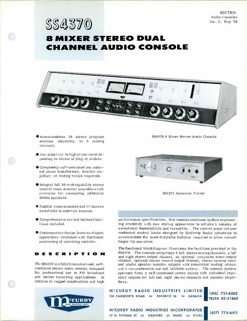
8 MIXER STEREO DUAL CHANNEL AUDIO CONSOLE
Accommodates 28 stereo program sources selectable to 8 mixing channels.
Any mixer can be high or low-level de- pending on choice of plug-in module.
Completely self-contained (no exter- nal power transformer, monitor am- plifier, or muting relays required).
Integral full 10 -watt capability stereo control room monitor amplifiers with provision for connecting additional studio speakers.
Control room monitors and VU meters switchable to external sources.
Comprehensive cue and talkbackfaci- lities included.
Contemporary design features elegant appearance combined with functional positioning of operating controls.
DESCRIPTION The SS4370 is a fully transistorized, self- contained stereo audio console designed for professional use in FM broadcast and stereo recording applications. In addition to rugged construction and high
SECTION: Audio Consoles
Iss. 2; May'68
SS4370 8 Mixer Stereo Audio Console
SS4371 Announce Turret
performance specifications, this console combines system engineer- ing creativity with new styling appearance to achieve a console of exceptional dependability and versatility. The control panel utilizes contoured control knobs designed by McCurdy Radio Industries to accommodate the most desirable features required to allow smooth finger-tip operation.
The functional blackdiagram illustrates the facilities provided in the SS4370. The console comprises 8 full -stereo mixing channels, a left and right stereo output channel, an optional composite mono -output channel, optional stereo record output channel, stereo control room and studio speaker monitor outputs with associated muting relays, and a comprehensive cue and talkback system. The console system operates from a self-contained power supply with individual regu- lated outputs for left and right stereo channels and monitor ampli- fiers.
MCCURDY RADIO INDUSTRIES LIMITED (416) 751-6262
108 CARNFORTH ROAD o TORONTO 16 c CANADA TELEX 02-21660
MCCURDY RADIO INDUSTRIES INCORPORATEDI (617) 774-6411
57 N. PUTNAM ST. o DANVERS c. MASS. c.+ 01923

0 0 0
V
e ;xi
0 0
o
o o -m
o
0 0 o
0 0
TL îJ,
0 G
«
T
e. I
e
[ .1"
II III' I !
I I II
rT1 r 1 r -i L J J L J LTJ L
I I II I I II
o
0
0 0
o
00 0 00 CI < I r
o o oò oò òo 00
e

Mixer positions 1 through 7 are provided with 3 -position stereo input selector switches. Mixer position 8 incor- porates a 5 -station stereopushbutton selector in addition to the 3 -position stereo selector key, and is designed and wired for remote lines. Any input pair of mixing channels may be used for high or low-level operation by employing the proper plug-in input modules. Low -impedance stereo mixing circuits are utilized throughout with high quality ladder type rotary controls to ensure freedom from mixing noise and to achieve long-term dependability. Muting relays operate in conjunction with the input and mixing keys, which are wired to a terminal block for optional strapping by the customer. Spare contacts prewired to terminal boards are included on all the lever keys toper - mit wiring to additional external control circuitry. (All mixer bus keys are wired for two -position stereo oper- ations plus a center OFF position. In one position the mixer feeds the stereo program bus; in the other position the mixer feeds a stereo record bus.)
Plug-in amplifier modules are employed within the con- sole system and provide performance characteristics which exceed all accepted broadcast standards for fre- quency response, noise, distortion, and dynamic range. State -of -the art techniques combined with time -proven silicon transistor circuitry achieve excellent performance and dependability. Operating voltage for the amplifier modules is obtained from an integral solid-state power supply. Plug-in power regulator modules provide excel- lent DC regulation of line and load variations.
A comprehensive monaural cue -intercom system is in- corporated in the SS4370. Attenuators with cue positions are supplied in each mixing channel and a separate un- balanced input permits independent cueing with respect to remote line and talkback selector switches. The use of an internal separate talkback microphone and cue speaker produces excellent intelligibility and simplified switching. Instant communication with two studio locations and stereo remote lines, without additional preselect controls, is provided by three lever keys conveniently located in the center of the control panel. A balanced bridging input to the 10 -watt cue amplifier enables a remote line to be monitored via the appropriate selector switch position. Additional external cue input positions are available on the remote line cue selector. An interlocked relay sys- tem routes the cue or talkback to the required location and prevents use in live microphone areas.
The SS4370 contains a high quality stereo monitoring system comprising two plug-in 10 -watt amplifier modules in addition to the 10 -watt cue amplifier. A ganged gain control and selector switch provide the necessary balanced stereo monitoring facility. The selector switch permits stereo monitoring of program transmission or three external stereo inputs. A "mono" position permits monitoring of the monaural output amplifier. The dual monitor amplifiers basically provide stereo monitoring facilities with relay muting circuitry for the control room speakers. Additional relay muted circuits are provided from these monitor amplifiers to feed Studio or Announce Booth monitor speakers. Where a more flexible stereo monitoring system is required for a studio or announce booth, the installation of an external
pair of monitor amplifiers, such as the McCurdy model ÁM411, is recommended.
Program levels are continuously monitored by two VU meters, and cue and monitor headset jacks. VU selector functions are in stereo with four external meter positions provided.
Additional facilities include provisions for an optional monaural output channel which is switchable to L, R or SUM signals, plus two external inputs.
Major amplifier and regulator components are fully modu- lar and plug-in. The console front panel and top cover are hinged to permit immediate access to all components, amplifiers, and wiring. Incoming and outgoing cables can be easily connected to turret -type solder terminals.
Flexibility of system modules, functional features, and a new design elegance combine to produce a stereo console of unsurpassed performance and versatility.
SPECIFICATIONS STEREO MIXING CHANNELS
A total of 8 are provided using ladder attenuators with cue positions.
PROGRAM INPUTS
A total of 28 stereo program sources may be connected to the input switching facilities of this console. Input channels 1 through 7 are provided with 3 -position selector switches. Input channel 8 includes a 5 -position push- button selector switch (to accommodate five remote lines) connected into one position of the 3 -position selector key.
The ratio of low-level inputs to high-level inputs in this console is determined by the type of input modules em- ployed in each input channel. The characteristics of the three basic input modules available for input channel application in this console are as follows:
Low Level Inputs - Equip with two AT240 preamplifier modules: -60 dbm nominal, -25 dbm max, 150 ohms balanced or unbalanced (May be strapped for 37. 5 ohms).
Matching High Level Inputs - Equip with two MT244 modules: -20 dbm nominal, +18 dbm max, 600 ohms balanced or unbalanced (May be strapped for 150 ohms).
Bridging High Level Inputs - Equip with two MT245 modules: 0 dbm nominal, +24 dbm max, 5K/20K ohms balanced or unbalanced.
AUX. INPUTS
(1) Two auxiliary program mixer bus inputs L and R, -26 dbm, 600 ohms, balanced. Each requires an MT244 input module to function (not supplied).
(2) Three external control room monitor inputs, -26 dbm, 600 ohms, balanced.

(3) Four external VU meter inputs to 'L' and 'R' VU circuits, +18 dbm, 600 ohms.
(4) Two external cue amplifier inputs, -20 dbm, 600 ohms balanced.
(5) One external cue bus input, -30 dbm, 600 ohms, unbalanced.
(6) Two external mono amplifier inputs, -30 dbm, 600 ohms.
OUTPUTS
(1) One stereo program line, +18 dbm, 600 ohms.
(2) One monaural program line, +18 dbm, 600 ohms (optional)
(3) One stereo record line, -45 dbm, 600 ohms bal- anced, using 2-MT244 output modules; -11 dbm, 600 ohms, (unbalanced) with 2-AT240 output modules.
(4) Three stereo monitor lines, +40 dbm (10 watts), 8 ohms: One Control Room, one Studio 1, one Studio 2, each equipped for independent relay muting.
(5) Two interlocked studio intercom outputs, +40 dbm (10 watts), 8 ohms.
(6) Two headset outputs, 0.77 volts, 5000 ohms: One Control Room stereo monitor, one Cue output.
GAIN (±2 db)
(1)
(2)
(3)
(4)
Microphone input to program output, 102 db.
High-level input to program output, 62 db.
Remote line input to program output, 62 db.
Microphone input to monitor output, 136 db.
FREQUENCY RESPONSE (ref 1 khz)
(1) For any input to program output at normal attenu- ator settings:
(a) Within ± 1.5 db, 20 hz to 20 khz.
(b) Within t 1 db, 30 hz to 15 khz.
For any input to monitor output at normal attenu- settings (with 12 db setting loss):
(a) Within ± 2 db, 30 hz to 20 khz.
(b) Within t 1.5 db, 30 hz to 15 khz.
NOISE (1) Relative input noise (microphone channels): -122 dbm unweighted, measured over 10 hz to 100 khz bandwidth.
(2) Signal to noise ratio (high-level channels): 68 db be- low +18 dbm output level with normal attenuator settings.
(2) ator
HARMONIC DISTORTION
(1) For any input to program output at normal attenu- ator settings: Less than 1%, 30 hz to 20 khz measured at +18 dbm output level.
(2) For any input to monitor output at normal attenu- ator settings: Less than 1%, 50 hz to 15 khz measured at +40 dbm (10 watts) output level.
CHANNEL SEPARATION (CROSSTALK)
At least 60 db below +18 dbm output level, when feeding one channel and measuring on unused channel, with normal attenuator settings, 30 hz to 15 khz.
POWER REQUIREMENTS
117/230v ac, 50/60 hz, single phase, 40 va. (normally connected for 117v operation).
AMBIENT TEMPERATURE
0°C to 55° C.
OVERALL DIMENSIONS
48 inches wide, 9 inches high, 20 inches deep.
WEIGHT
Console less plug-in components: 144 lb.
ORDERING INFORMATION (1) The basic SS4370 console includes:
One 10 -watt stereo monitor amplifier system. One 10 -watt cue amplifier. Two program output amplifiers, booster ampli- fiers, and necessary power supply components.
Less all input modules.
(2) Specify, for a total of 16,the following input options (in pairs)
AT240 Microphone Preamplifier. MT244 Matching Input Transformer. MT245 Bridging Input Transformer.
OPTIONS
Monaural output channel: One AT242 program amplifier.
Record output channel: Two AT240 booster ampli- fiers or two MT244 isolation transformer modules.
ACCESSORIES
SS4371 Announce Turret
SS4360-1 Control Desk and Pedestals.
SA600 Warning Light Relay Panel.
SS4408 Turntable Remote Control Panel.
SS4409 Reel Tape Remote Control Panel.
SS4410 Cartridge Tape Remote Control Panel.
AM411 Dual Monitor Amplifier Assembly.
The SS4370 console is also available in a complete custom - engineered stereo studio package complete with announce turret, turntables, cartridge tapes, and reel tapes. Write for more details.
For monaural applications please request the SS4360 brochure.
TRANSIENTS The operation of any relay in the console will not degrade the noise figure by more than 6 db.
McCurdy Radio Industries reserves the right, without notice, to make such changes in equipment, design, specifications, or components as progress in engineering
or manufacturing techniques may warrant to improve the performance of the product.

gg2320 AUDIO
Six mixers, normally consisting of two microphone and four high level.
Completely self-contained, including power supply, 10 -watt monitor, and speaker muting relay.
Professional slider attenuators and full-size vu meter.
Plug-in modules used for all major components - silicon solid-state cir- cuitry throughout.
Optional units include audio -follow - video switcher and pushbutton cue panel.
Built-in script board. Walnut end bells add to attractive functional design. Made for desk -top mount- ing.
wo IMOY/T.11 1IW11C
SECTION: Audio Consoles
Iss. 2; Nov. '68
SOLID-STATE BOOTH CONSOLE
DESCRIPTION The SS4380 Solid -State Audio Booth Console presents a new approach to audio console design, from both the physical and electronic stand- points. The SS4380 is a six -mixer console designed for small installations where a full-size console is not required, and is ideally suited for the announcer -operated booth.
The overall design of the SS4380 presents a compact, attractive, and functional unit at moderate cost, without sacrifice of quality or utility. In spite of its small size, the SS4380 is completely self- contained with integral power supply, 10 -watt monitor, and muting
MCCURDY RADIO INDUSTRIES LIMITED (416) 751-6262 108 CARNFORTH ROAD O TORONTO 16 O CANADA TELEX 02-21660
MCCURDY RADIO INDUSTRIES 1051 CLINTON STREET 0 BUFFALO G N.Y. 14206 (716) 854-6700

cc O o o O S Hcr U î w z
d 0 îN m
cr W Y >a U N
3 N
m U
W
- M N Q - N M O N i0 f- / CO 0 m I H O J O > 1D telQJ
Z> 1
C1 S>>O H Oa f ==p ói'n
1
O m
c fA
J Q Z O H a O
>-
Q
7 U
J
circuit. All modules are silicon, solid-state, plug-in units of the highest quality and incorporate proven cir- cuitry. The attenuators are professional, constant - impedance, slider type providing smooth, uniform operation.
The console is designed for mounting in a cutout in a desk top, and projects only 5 inches below the desk top. The compatible color scheme of brushed anodized alumi- num and textured acrylic blue is further enhanced by genuine walnut end panels. A central script board with roller -type script holder adds that extra touch to an already impressive design.
FACILITIES
The block diagram shows the facilities of the SS4380. The console includes six mixer channels, one program channel, and one 10 -watt monitor amplifier as standard equipment.
Program Circuits
Each mixer can accommodate two inputs, selectable by a three -position input key (INPUT 1/OFF/ INPUT 2). The first two mixers will accept levels of -70 vu, 150 ohms, via built-in preamplifiers which raise the signal to a level suitable for mixing. The remaining four channels are high level (-4 vu, 600 ohms) and feed the mixing bus directly. Constant -impedance, stepped attenuators adjust the levels fed to the mixer bus. As an option, Mixer No. 3, which is normally high level, may be fitted with a preamplifier for conversion to a microphone channel.
Monitoring
Continuous visual monitoring of the program output (+8 vu, 600 ohms) is provided by a full-size, A -scale, illu- minated vu meter. In addition, speaker monitoring is obtained from an AT263 10 -watt Monitor Amplifier, which is included as standard equipment. The output trans- former is optional, and normally is required only for long speaker runs. The speaker muting circuit consists of a relay and a unique transistorized switching circuit which effectively eliminates all transients. Convenient dual headset jacks allow monitoring of program and cue outputs.
OPT IONS
SS4380-1 Cue Assembly
The optional SS4380-1 Cue Assembly mounts on a panel to the right of the SS4380 control panel. This self- contained unit utilizes pushbutton selection of up to twelve inputs and incorporates its own amplifier, speaker, and regulated power supply. A unique feature of the cue assembly is that it permits cueing of inputs before the console mixer selector key; this prevents accidental 'cueing on air' since it does not act on the console cir- cuit itself. An output is provided to the cue headset jack.
SS4380-2 Audio -Follow -Video Switcher
This optional unit consists of a relay assembly utilizing up to eight plug-in relays. These are wired in parallel with the mixer input selector keys, duplicating their action. This allows remote input control by an external control panel or switcher. The normal control voltage required is 24v dc. The relay coils are fully suppressed to eliminate switching transients.
SPECIFICATIONS INPUTS
(1) Four microphone inputs, -70 vu (-60 dbm) 150 ohms, selectable to two mixer channels by three -position keys.
(2) Eight high level inputs, -4 vu (+6 dbm) 600 ohms, selectable to four mixer channels by three -position keys.
(3) One air cue input, -4 vu (+6 dbm) 600 ohms, to optional cue system.
OUTPUTS
(1) Two fixed program outputs, +8 vu (+18 dbm) 600 ohms.
(2) One program headset output, 1 volt into 5K load.
(3) One program monitor output, 10 watts, 8 ohms. Muting relay included.
MAXIMUM GAIN (±1 db)
(1) Microphone input to program output: 102 db.
(2) High level input to program output: 36 db.
FREQUENCY RESPONSE (ref 1 khz)
(1) For any input to program output at normal attenuator settings: Within ±1 db 30 hz to 20 khz.
(2) For any input to monitor output at normal attenuator settings: Within ±1 db 50 hz to 15 khz.
NOISE
(1) Relative Input Noise: -122 dbm, unweighted, meas- ured over 10 hz to 100 khz bandwidth at -3 db points.
(2) Signal -to -Noise: 62 db below +18 dbm output level with normal attenuator settings.
HARMONIC DISTORTION (at normal attenuator settings)
(1) For any input to program output: Less than 1%, 30 hz to 20 khz, at +18 dbm output level.
(2) For any input to monitor output: Less than 1.5%, 30 hz to 15 khz, at +40 dbm (10 watts) output level.

ISOLATION BETWEEN OUTPUTS
(1) A signal fed into output No. 1 will appear on output No. 2 at least 32 db below the impressed level.
(2) An open circuit or short circuit on any program out- put of the console will not affect the level of any other output by more than 0.25 db.
POWER REQUIREMENTS
AMBIENT TEMPERATURE
0°C to 55° C.
OVERALL DIMENSIONS
28 in. (71.1 cm) wide, 18-1/2 in. (47 cm) deep, 6 in. (15.24 cm) high plus 5 in. (12.7 cm) projection below desk top.
WEIGHT 117/230v ac, 50/60 hz, single phase, 40 va. Normally connected for 117v operation. 72 lb (32.7 kg).
ORDERING INFORMATION BASIC CONSOLE
The basic SS4380 comes equipped with:
OPTIONAL ACCESSORIES
(1) Extra preamplifier for optional channel 3 microphone input.
(1) Two microphone -level mixers at 150 ohms. (2) SS4380-1 Cue Assembly.
(2) Four high-level mixers at 600 ohms. (3) SS4380-2 Audio -Follow -Video system.
(3) One 10 -watt monitor channel. (4) MRI 3004 monitor output transformer.
McCurdy Radio Industries reserves the right, without notice, to make such changes in equipment, design, specifications, or components as progress in engineering or manufacturing techniques may warrant to improve the performance of the product.

g2,322 CHANNEL
Eight mixer channels, all equipped with preamplifiers and rotary step attenuators.
Two inputs per mixer channel, se- lectable by input keys.
Ten amplifiers and regulated power supply within console, all plug-in modules and completely silicon solid- state.
Four additional unwired utility keys with provision to add four more.
Ten -position pushbutton cue assem- bly, complete with self-contained speaker amplifier .
SECTION: Audio Consoles Iss. 1; Dec '69
8 -MIXER SINGLE - AUDIO CONSOLE
Monitor control and feed for external monitor amplifier.
Special feature - provision for optional, console -mounting, re- cessed pushbuttons for remote control of external equipment such as turntables, tape recorders, etc.
Desk -top dimensions 6 in. high, 18-1/2 in. deep, 28 in. wide.
McCURDY RADIO INDUSTRIES LIMITED (416) 751-6262 108 CARNFORTH ROAD O TORONTO 16 fl CANADA TELEX 02-21660
MCCURDY RADIO INDUSTRIES INCORPORATED (716) 854-6700 1051 CLINTON STREET o BUFFALO G N.Y. 14206

DESCRIPTION The SS4388 Audio Console is an eight -mixer single - channel console providing professional facilities for the mixing, monitoring, and control of audio program material. The SS4388 is designed for installations not requiring the use of a full-size console, such as News Booth or Disc Jockey areas. In this regard, the SS4388 offers compactness and convenience while maintaining full broadcast specifications. These important features are achieved without over -miniaturization or crowding of internal and external components.
The SS4388 includes a comprehensive cue system and is self -powered by means of an internal, regulated, power supply. All amplifiers and the power supply are standard McCurdy plug-in modules incorporating proven silicon solid-state circuitry. Operating controls are arranged for optimum separation combined with grouping of related functions, and recessed panels are provided for do control switches (optional) .
The SS4388 is designed for mounting in a cutout in a desk top (see Dimensional Outline Diagram) . The extremely low silhouette permits the operator an unobstructed view into adjoining areas - a desired feature in many installa- tions.
The front panel presents a highly attractive appearance with its combination of light blue acrylic panels and dark blue plexiglas escutcheons. Genuine walnut end bells add contrast and enhance the overall quality of the design.
FACILITIES
The facilities of the SS4388 are shown in the Block Diagram. The console incorporates eight mixer channels ,
one program channel, and a complete cue system, along with monitor and PA feeds.
Program Circuits
Each mixer accommodates two inputs, selectable by a three -position lever key. One position selects a low- level input (-60 vu, 150 ohms) and the other position selects a high-level input (0 vu, 600 ohms); the center position of the key is a terminated 'off' position. The key selections are identified by means of designation strips, rather than engraving, so that the customer may designate these as desired.
CH. I
A O
B 150? O 0 -60
C OJ?? 'A' INPUTS= -60VU,15011
INPUTS = 0 VU ,60011
AO
CH 2 THRU CH 7
NOT SHOWN
CH 8
C 0-1A/V-9
1156 AC 50/60 Hz
PS 876/36
POWER SUPPLY
AT 247 (+65 )
AI
124 (-12)
A8
(-34)
-/\./V`
(-35)
0
36 V DC REGULATED
24V DC UNREGULATED
-4
M26002 (+68)
(-56) -"\AAA --1
+14
150/20K
I/L
L
L
)-
L
F
CUE SELECT
(-6) LINE +8 VU 60011
AUX +8 VU 60011
e HOST O
( EOV.VU .7805K1i V)
O
(-24) MON. F PA.
1-U
AT 247 (+65) CUE
GAIN
A9 -10
(-15)
-10 VU soon
4 UTILITY KEYS
O (UNWIRED)
O. --o
CUE AMP
O
SS4388 Functional Block Diagram

The input channels employ McCurdy AT247 Amplifiers to raise the selected input audio to a suitable level for mix- ing. The mixing level is adjusted by means of premium - quality rotary attenuators which are connected in the interstage sections of the amplifiers.
The mixer bus feeds the single program channel which uses a McCurdy M26002 Program Amplifier. The final output level is adjusted by means of a high -quality potentiometer which controls the gain of the M26002. Two program output splits are provided, consisting of one Line output and one Auxiliary output, both at +8 vu, 600 ohms.
Monitoring and PA
Continuous visual monitoring of the program channel is provided by a full-size A -scale illuminated VU meter. Local aural monitoring is available at a headset jack (0 vu, 5K) located on the front of the console. In addition, two -10 vu 600 -ohm outputs are provided for feeding external monitor and PA amplifiers . A muting relay for the monitor, and a common gain control for both out- puts, are supplied as standard equipment. A complete 10 -watt speaker -amplifier system is available to accom- modate this output (model LSA608 or LSA 609) .
Cue System
Each preamplifier provides a continuous cue output which is taken off ahead of the mixer attenuator. The program channel provides a cue output via a 20K bridging trans- former. These outputs are coupled through high -isolation pads to the cue pushbutton assembly for selection to the cue channel. This channel provides up to 2 watts to the built-in cue speaker, with a front panel control providing level adjustment. A muting relay is included.
Utility Keys
Four, three -position, utility keys are supplied as standard equipment, with provision to add four more as an extra - cost option. These can be used for dc control, intercom, etc . The utility keys are unwired on the standard console.
OPTIONS
Four recesses in the lower part of the front panel are designed to accommodate optional pushbutton assemblies for do control of turntables, tapes, etc. McCurdy has a complete line of these assemblies, plus an intercom key panel designed to fit these locations. (See Ordering Information) .
SS4388 Dimensional Outline
SPECIFICATIONS INPUTS
(1) Eight low-level inputs, -60 vu (-50 dBm) 150 ohms.
(2) Eight high level inputs, 0 vu (+10 dBm) 600 ohms.
OUTPUTS
(1) One program line output, +8 vu (+18 dBm) 600 ohms (matching) .
(2) One auxiliary output, + 8 vu (+18 dBm) 600 ohms (bridging).
(3) One program headset output, 0 vu (0.780v equiv.) 5,000 ohms .
(4) One program monitor output, -10 vu (0 dBm) 600
ohms. Muting relay included.
(5) One PA output, -10 vu (0 dBm) 600 ohms .
MAXIMUM GAIN (± 1 dB)
(1) Low-level input to program output: 92 dB.
(2) High level input to program output: 32 dB.
Low level input to monitor output: 84 dB.
(4) High level input to monitor output: 24 dB.
(3)
FREQUENCY RESPONSE (ref 1 kHz)
For any input to program, monitor, or PA output at
STANDARD CONSOLE
normal attenuator settings: ± 1 dB from 30 Hz to 15
kHz.
NOISE
Relative Input Noise: -122 dBm, unweighted, measured over 10 Hz to 100 kHz bandwidth at -3 dB points.
HARMONIC DISTORTION (at normal attenuator settings)
(1) For any input to program output: less than 0.5% from 30 Hz to 15 kHz at +18 dBm output.
(2) For any input to monitor output: less than 0.5% from 30 Hz to 15 kHz at 0 dBm output.
TRANSIENTS
The operation of any relay in the console will not degrade the noise figure by more than 6 dB.
POWER REQUIREMENTS
115 vac, 50/60 Hz, single phase, 30 va approxi- mately.
AMBIENT TEMPERATURE
0°C to 55°C.
OVERALL DIMENSIONS
28 in. (71.1 cm) wide, 18-1/2 in. (47 cm) deep, 6 in. (15.24 cm) high plus 8-1/2 in. (21.6 cm) projection below desk top.
ORDERING INFORMATION
The standard SS4388 Audio Console incorporates all the equipment shown in the Block Diagram.
OPTIONAL EQUIPMENT
(1) Turntable/Tape Control Pushbuttons. Space is pro- vided for up to eight units (two per recessed panel) . Each unit can be one or two pushbuttons, momentary, locking, or interlocking. Specify when ordering.
(2) Intercom Key Panel. Occupies one recessed panel and holds up to four three -position keys. Each key can be momentary or locking in either or both activated posi- tions. Specify when ordering.
(3) Up to four extra Utility Keys. Specify desired con- figuration (momentary, locking, or combination of these) .
(4) LSA608 or LSA609 10 -Watt Speaker/Amplifier.
The price listed for the standard console does not include optional equipment nor the installation of optional equip- ment.
3
McCurdy Radio Industries reserves the right, without notice, to make such changes in equipment, design, specifications, or components as progress in engineering
or manufacturing techniques may warrant to improve the performance of the product.

SS 77 series
modular audio production
For TODAY'S BROADCAST INDUSTRY and RECORDING STUDIOS
o

description
The SS7700 Series of modular audio consoles provides complete professional facilities for mixing and shaping today's complex audio material. The equipment features modular construction, which combines an almost unlimited scope for custom- izing with maximum economy, a carefully thought- out control panel layout, based on providing max- imum operating comfort and convenience in the minimum adequate space, performance specifica- tions well within recognized broadcast standards, and, of course, a pleasing appearance.
In addition to complete program mixing, moni- toring and control, SS7700 Series consoles pro- vide PA feeds and comprehensive Solo/Cue, Echo-Send/Receive, Foldback and Talkback sys- tem facilities. A full range of options is also avail- able including Equalizers, Compressors, Program Assign with Pan, and Remote Controls.
EASY TO CUSTOMIZE AND EXPAND
The modular basis of SS7700 Series design makes it easy and economical to customize a console to meet the exact requirements of a part- icular application. Similarly, later expansion to a maximum of 26 functional channels (which may consist of almost any mix of input channels, sub - masters and masters) is simply a matter of install- ing the desired modules in prewired receptacles in the control panel. An optional companion hous- ing styled similarly to the console is available to accommodate the ancillary equipments required for some applications.
A PLEASURE TO OPERATE
SS7700 Series consoles are designed to pro- vide the maximum degree of operating comfort and convenience, consistent with the realities of human and equipment dimensions. To the great- est extent possible, all controls are located in uncrowded groupings of related usage, within easy reach from a sitting position. All control knobs and switch buttons are large enough to per- mit positive, precise operation and are placed so that their operation does not interfere with ad- jacent controls. The large, easy -to -read VU meters are located in a low -silhouette panel which gives the operator an unobstructed view of adjoining areas.
RELIABLE AND EASILY MAINTAINED
Field -proven McCurdy solid-state plug-in mod- ules are used throughout the console. When ser- vicing is required, the complete control panel hinges upward, providing maximum accessibility.
ATTRACTIVE STYLING
While the philosophy behind the design of the SS7700 Series equipment has been to provide a superbly functional and flexible product, aesthetic aspects have not been neglected. The console end bells and the VU meter housing are made of richly -toned, hand -rubbed, oiled walnut. The sur- face of the control panel is finished in a wood - grain pattern overlay, surrounded by style strips of clear anodized aluminum which eliminates glare and reflections, and resists damage. A padded arm rest adds to both the appearance and the oper- ating comfort of the console.
FACILITIES AND OPTIONS
The standard and optional facilities of SS7700 Series consoles are illustrated in the functional block diagram on page 4.
2

facilities &options
MIXER -CHANNEL INPUTS TO PROGRAM -CHAN- NEL OUTPUTS
A choice of six input modules including Echo - Return accommodates any mixer input level from -70 to +8 dBm nominal. Input sensitivity switches compensate for higher and lower input levels. The normal complement of input mixer -channels is up to 20 and may be expanded to 26 if required. The standard IM7701 Input Module in each mixer - channel nominally accepts microphone (low- level) inputs of -70 to -20 dBm and high-level inputs of -20 to +8 dBm, at impedance levels of 150 and 600 ohms respectively, with 40 dB dynamic range in reserve for microphone peaks. A sensitivity selector with phase reversal provides a convenient means of accommodating various inputs from microphone to line -level at the turn of a switch. The selector is calibrated for the most common level/impedance combinations used in the industry.
NOTE: The optional IM7702, IM7704, IM7705, and IM7706 High -Level Amplifier Input Modules ac- commodate input levels of -10 dBm nominal to +20 dBm maximum (depending on the attenuator setting used)/600 ohms matching. The optional IM7703 High -Level Bridging Input Module accom- modates inputs of +8 dm nominal to +20 dBm maximum.
The mixer output level in each channel is ad- justable by a high -quality slide attenuator. An op- tional EQ155 Variable Equalizer module may be inserted in the output of each mixer -channel.
EACH MIXER CONTAINS:
A channel -on (CH ON) latching type pushbutton. Solo and Cue momentary -on pushbuttons.
Two 3 -position (center -off) rotary switches for selection of PRE/POST Fade modes of Echo -Send and Foldback respectively.
A calibrated rotary step selector switch for sensitivity and input impedance adjustment, con- centric with a separate switch for Phase Reversal of the input signal.
Mixer outputs are bussed to the SM7715 Sub Assign Modules consisting of 4 -Submaster and 2 -Master Select latching type pushbuttons. Any number of mixers may be grouped and assigned to any one or all submasters. An optional feature of the basic Assign Module is provision of sub - bypass pushbuttons (Master Select) which allows the inputs to be mixed into the masters directly.
Appropriately grouped mixer outputs are fed to the SM7711 Summing and Booster Amplifier Sub- master Modules. These modules use the same type of slide attenuators and optional variable equal- izers as used in the mixer modules. This module also has an output CH ON latching pushbutton plus Solo and Cue feeds selected by momentary - on pushbuttons. An optional SM7712 Submaster Module performs the same functions as the SM7711 and has in addition Echo -Send and Fold - back feeds with gain controls.
Outputs from the SM7711 modules are routed as follows: Either ahead of the output CH ON pushbutton to their respective Submaster Auxiliary Amplifier in- put, bypassing the PM7725 Program Assign Mod- ule, to provide VU meter indication, monitor select and auxiliary recording output splits at +8 dBm or, via the CH ON pushbuttons and the PM7725 Program Assign Modules directly to the respective Master Program -Channel selected.
Submasters selected by the Program Assign pushbuttons are routed to the PM7722 Summing and Program Amplifier Modules. The output gain of these modules is controlled by a slide attenua - tor on the control panel. Each program -channel provides a line output via a CH ON pushbutton, and two direct outputs at a nominal output level of +8 dBm/600 ohms plus separate VU meter and Monitor Select splits. However, as with other facil- ities of the SS7700 Series, the output configuration can be varied. An optional PM7721 Program Mod- ule performs the same functions as the PM7722 but with an integral rotary gain control. Optional compressor modules are available for insertion in the line outputs of systems requiring this facility.
3

facilities &options SOLO/CUE!TALKBACK
Each mixer, submaster, and the echo -return input module can be cued or selected as a solo by momentary -on pushbuttons to separate busses, which feed their respective amplifier modules. Their gains are adjusted by control panel attenu- ators associated with their output amplifiers. Mut- ing of these outputs is possible by means of relays provided. The Solo bus feeds an SN292 Summing Amplifier that drives an AT285 Medium -Level Am- plifier providing a nominal monitor output level of -10 dBm/600 ohms. The Cue bus feeds a CM7441 Cue and Talkback Amplifier Module, pro- viding a maximum 2 watts/16 ohms to a console speaker. Three -20 dBm external Cue inputs selectable by interlocking pushbuttons, and two studio Talkback inputs selectable by momentary - on pushbutton relay controls, are provided in the CM7441 module, in addition to a Talkback Micro- phone input.
ECHO -SEND ECHO -RETURN
Each channel input module contains a 3 -posi- tion center -off rotary Echo -Send switch that selects either PRE or POST Fade Echo -Send modes. A rotary level control feeds the selected Echo -Send output to a PM7721 Program Module. Two balanced Echo -Send outputs, controlled by a common rotary gain control, are provided by the PM7721 at a nominal output level of +8 dBm/ 600 ohms.
An Echo -Return level of -10 dBm may be ap- plied to the 600 -ohm matching input of the IM7704 Medium -Level Input Amplifier Module. The output is fed via a gain control and CH ON pushbuton to the sub and master select pushbutton circuits of the SM7715 Sub -Assign Module. The submaster and master select pushbuttons may select the Echo -Return to any or all submasters and master program outputs. An optional IM7705 module per- forms the same functions and has in addition a Foldback facility.
FOLDBACK
Each channel input module contains a 3 -posi- tion center -off rotary Foldback switch, and a con- centric level control, that selects either PRE or POST Fade Foldback modes. The level control feeds the selected Foldback output to a second PM7721 Program Module. Two balanced Foldback outputs, controlled by a common rotary gain con- trol, are provided at a nominal output level of +8 dBm/ 600 ohms. This system is electrically identical to the Echo -Send facility.
PAN
As an optional feature, a PP7751 Program As- sign Module with PAN may be used in place of the PM7725 Program Assign Module, to provide an adjustable PAN input between the two master program -channels. PAN is selectable by a latching type pushbutton.
MONITORING
Continuous visual monitoring of each submaster and master program -channel is provided by sepa- rate full size A -scale illuminated VU meters. Audio monitoring is provided by two headset jacks (0 dBm/5K-ohms) located at the front of the console below the control panel. Interlocking Monitor Se- lect pushbuttons permit selection of a submaster or master program -channel, or one of three ex- ternal feeds to the monitor -channel. All inputs are bussed via a pair of normally -closed contacts on the Solo relay to an AT285 Medium -Level Input Amplifier, providing a nominal gain controlled output level of -10 dBm. A muting relay is pro- vided. Optional 10 -watt or 50 -watt speaker -ampli- fier systems, McCurdy types LSA609 or LSA611 respectively, are available for this monitor output.
POWER SUPPLIES
Four PS876A/48 Regulated DC Power Supplies are used in the SS7700 Series. DC distribution throughout the entire console is so arranged that failure of any one supply will cause only a mini- mum of inconvenience. The amplifiers are powered by +48 Vdc and all lamps and relays by +24 Vdc. These power supplies are provided with overload and short-circuit protection features with provision for remote sensing of load conditions. The PS876A/48 is a functionally -proven, high reliability power supply of silicon solid-state circuitry.
4

functional
ñ
mi
L
_J
i;
L- l
rw Ix! ;xl
Lx i
II
_i i
---J
ix ix L._ L_
o O
L. -
I Lrl I i
`
0 0
1 I
! -;. ! I
I! I !Q
II
º
I
iiie---
VI "o-.vn-(-
i
L- --------i Q Q i
r1r i rYFI Ix! i x i
i I
i j ixi xi ixj x x,
r Ix! J L.J
I
xx
r
r
o o 2 "
¡ I
L'! ; i
î .1J
' i
W
I r._J 1 : I i ç Ì I
1
I á i c
Í ai i
I i s
i =I
I L.
o
z C
5
SM 7715
IM7701
SM7711
I M 7702
PM 772°.5
1M7706
PP7751
IM 7704
HF+ fiti 9
12 b
b 10
=
s 3 p 2
a LF+
56 Min Max
LEVEL
10
EQ155
PM7721
(A) Faders
(B) Input Modules
(C) CH -ON
(D) Solo (E) Cue
(F) Echo Send
(G) Foldback (H) Sensitivity (I) Equalizers (J) Sub Assigns (K) Master Assigns (L) Talkback Speaker (M) VU Meters (N) Cue/Talkback Speaker (0) Equalizers (P) Compressors (Q) Echo Return (R) Sub -Master Program (S) Master Program (T) Talkback Controls (U) Studio Monitor (V) Control Room Monitor
PM7722 CM7441
30 OFF
4 40 20 20 1/
61 E,
..3
- PHASE +
-+ . PFf'
OFF POFT
FOLDBACK
PFE OFF
POSE
ECHO SEND
CUE SOLO
CH ON
CUE SOLO
CH ON LINE ON
6

modules &functions
STANDARD MODULES
IM7701 INPUT MODULE - Microphone and high- level inputs with sensitivity switch; -70 to -20 dBm/150 ohms and -20 to +8 dBm/600 ohms.
IM7704 INPUT MODULE - Medium -level input; -10 dBm/600 ohms matching. Typically used as Echo -Return input.
SM7715 SUB ASSIGN MODULE - 4 Sub and 2
Master selects.
SM7711 SUB MODULE - Summing and Booster Amplifier
PM7725 PROGRAM ASSIGN MODULE -2 Master Selects.
PM7722 PROGRAM MODULE - Summing and Program Amplifier, controlled by a slide attenuator (fader).
PM7721 PROGRAM MODULE - Summing and Program Amplifier, controlled by a rotary attenu- ator. Typically used in Echo -Send and Foldback amplifiers.
CM7441 CUE AND TALKBACK MODULE - 2W/16 ohms output with 3 external Cue inputs, 2 external Talkback inputs, and a Talkback Microphone input.
SN292 SUMMING AMPLIFIER - Typically used as Solo amplifier to monitor output.
AT285 MEDIUM -LEVEL AMPLIFIER - with rotary gain control. Typically used as monitor output amplifier, -10 dBm/600 ohms.
AT297 HIGH-LEVEL BRIDGING AMPLIFIER - capable of six output splits. Typically used as Submaster auxiliary output.
PS876A/48 REGULATED DC POWER SUPPLY - Regulated +48 Vdc output to amplifiers and +24 Vdc to the lamps and relays.
OPTIONAL MODULES
IM7702 INPUT MODULE - optional to IM7701. Fixed input, -10 dBm/600 ohms matching.
IM7703 INPUT MODULE - optional to IM7701. Fixed input, +8 dBm/bridging 600 ohms.
IM7705 INPUT MODULE - optional to IM7704 with Foldback added.
IM7706 INPUT MODULE - optional to IM770t with Echo -Send added.
SM7712 SUB MODULE - optional to SM7711 with Foldback and Echo -Send added.
SM7713 SUB MODULE - optional to SM7711 less Solo and Cue.
PM7721 PROGRAM MODULE - optional to PM7722, with an integral rotary gain control.
PP7751 PROGRAM ASSIGN MODULE - optional to PM7725 with PAN added.
7

summary of facilities 1. Up to 20 mixer -channels, 4 submasters and
master program channels as required. 2. Straight-line faders (slide attenuators) on all
channels. 3. Cue and Solo on all mixing channels via
momentary -on pushbuttons. 4. Echo -Send and Foldback busses. 5. Sensitivity and Phase Reversal on all mixing
channels. 6. Equalizer insertion facility on all mixing
channels. 7. Sub and Master Assign pushbuttons on all
channels. 8. Up to 8 Program and Submaster VU meters. 9. Cue and Talkback Speakers including an
external Talkback Speaker facility. 10. Compressor insertion facility in the program
outputs. 11. Echo -Return Control. 12. Talkback Controls. 13. Studio and Control Room Monitors. 14. External Cue Inputs.
PROGRAM INPUT SELECTION
1. Two inputs on each mixer -channel; micro- phone and high-level.
2. All channels have capability to accommodate low, medium or high-level inputs depending on the input module installed or whether input sensitivity selectors are installed; (a) Low and high-level inputs; Input Module IM7701, -70 to -20 dBm/150 ohms and -20 to +8 dBm/600 ohms, balanced or unbalanced, with sensitivity switch and phase reversal. Optional input modules IM7702 fixed input -10 dBm/600 ohms matching and IM7703 fixed input +8 dBm/bridging 600 ohms. (b) Medium -level inputs: Input Module IM7704, -10 dBm/600 ohms matching, slide attenuator with Cue and Solo. Optional input modules IM7705 and IM7706, same as IM7704 with Foldback and Echo -Send respectively added.
AUXILIARY INPUTS
1. One Echo -Return to mixers, -10 dBm/600 ohms matching.
2. Three external Cue inputs. 3. Three external Monitor inputs. 4. Two external Talkback inputs. 5. Optional Talkback microphone.
OUTPUTS
1. Submaster and Master program -channels as required, individually VU meter monitored. Each channel is selectable to a program line via CH ON pushbuttons. Level: +8 vu (+8 dBm) 600 ohms balanced.
2. Monitor -channel has a muting relay and gain control. Level: -10 dBm/600 ohms. Optional LSA609, or LSA611 speaker - amplifiers are external.
3. One Echo -Send channel output. Level: +8 dBm/600 ohms.
4. One Foldback channel ouput. Level: +8 dBm/600 ohms.
5. One Cue/Talkback speaker output. Level: 2W (maximum)/16 ohms.
6. Two Headset outputs. Level: 0 dB/5K ohms .
8

specifications
GAIN (± 2 dB)
1. Microphone input to program output: 114 dB maximum with submasters.
2. Medium -level input to program output: 54 dB with submasters.
3. High-level input to program output: 36 dB maximum with submasters.
FREQUENCY RESPONSE (REFERENCE 1 kHz)
1. For any input to any program output at normal attenuator settings (i.e. 10 dB below maxi- mum levels specified): ±0.5 dB from 30 Hz to 15 kHz; ±1.0 dB from 20 Hz to 20 kHz.
2. For any input to monitor output at normal attenuator settings (with 10 dB in monitor) ±1.0 dB from 30 Hz to 20 kHz.
TOTAL HARMONIC DISTORTION (TYPICAL PRO- GRAM PATHS)
Measured at 10 dB above normal operating levels (i.e. at maximum levels specified):
1. Low-level inputs: 0.5% or less at any fre- quency from 30 Hz to 20kHz.
2. High-level inputs: 0.5% or less at any fre- quency from 30 Hz to 20 kHz.
3. Monitor Channel: Less than 0.5% from 30 Hz to 15 kHz
SIGNAL-TO-NOISE RATIO
Low-level inputs: Equivalent input noise of -124 dBm for -70 dBm input unweighted, (i.e. 64 dB below +8 for a -70 dBm microphone input) measured over a bandwidth of 10 Hz to 100 kHz at the -3 dB points.
CROSSTALK
At least 60 dB below +18 dBm output level when feeding one channel and measuring an unused channel, 30 Hz to 15 kHz, at normal attenuator settings 12 dB in -hand.
TRANSIENTS
The operation of any attenuator or switch in the console shall not degrade the noise figure by more than 10 dB.
POWER REQUIREMENT
117 Volts ac, 50/60 Hz, 3 -wire single phase, 950 VA maximum. (Can be supplied for 230 Volts on special order).
9

expansion to SS7800 The expansion of the basic SS7700 console to
an SS7800 incorporates a console structure 18 inches longer, providing additional space for 11 extra modules. Within this expanded area, ad- ditional facilities may be added which would in- clude the following:
(a) the inclusion of jackfield facilities. (b) Ancillary equipment controls such as machine
controls for tapes, carts, turntables, etc. (c) Further expansion of the mixer or other in-
puts, submaster and master program chan- nels.
10

installation
TOP
56" 1422 mm.
©l PADDED ARM REST
19" (483 mm) STD. SPACE - (FRONT REAR)
FRONT
12" 304 mm.
29" 737 mm.
30" 762 mm.
343/." 856.5 mm.
WALNUT HOUSING AND END BELL
REMOVABLE END BELL AND SUPPORT
SIDE SUPPORT (CHROME)
41" 1041 mm.
11

ordering information STANDARD EQUIPMENT
1. Specify type and quantity of input module desired from the following: (a) IM7701 Microphone and High -Level Mod- ule, -70 to -20 dBm/150 ohms and -20 to +8 dBm/600 ohms matching, c/w sensitivity switch and phase reversal, PRE and POST Fade Echo -Send and Foldback feeds and CH ON pushbutton. (b) Optional IM7702 Fixed Input Module, -10 dBm nominal to +20 dBm/600 ohms matching, PRE/POST Fade Echo -Send and Foldback feeds, Solo and Cue feeds. (c) Optional IM7703 Fixed Input module, +8 dBm nominal to +20 dBm/bridging a 600 ohm line, PRE/POST Fade Echo -Send and Foldback feeds, Solo and Cue feeds.
2. Specify type and quantity of submaster mod- ules desired from the following: (a) SM7711 Summing and Booster Amplifier Module c/w Solo and Cue feeds and CH ON pushbuttons. (b) Optional SM7712 Summing and Booster Amplifier Module - Same as SM7711 plus Echo -Send and Foldback feeds. (c) Optional SM7713 Summing and Booster Amplifier Module - Same as SM7722 less Solo and Cue feeds.
3. Specify type and quantity of master program assign modules desired from the following: (a) PM7725 Master Program Assign Module with 2 -Master Selects. (b) Optional PP7751 Master Program Assign Module - Same as PM7725 but with PAN added.
Printed in Canada
4. Specify type and quantity of master program output modules desired from the following: (a) PM7722 Summing and Program Amplifier Module, +8 dBm/600 ohms, c/w VU meter and Monitor Select feeds, latching type Line ON pushbutton and slide attenuator gain control. (b) Optional PM7721 Summing and Program Amplifier Module - Same as PM7722 but with an integral rotary gain control.
5. Specify type of echo -return input module desired from the following: (a) IM7704 Medium -Level Input Amplifier Module, -10 dBm/600 ohms matching, ex- ternal gain control, Solo and Cue feeds, and a latching CH ON pushbutton. (b) Optional IM7705 Medium -Level Input Amplifier Module - Same as IM7704 plus a Foldback feed. (c) Optional IM7706 Medium -Level Input Amplifier Module - Same as IM7704 plus an Echo -Send feed.
OPTIONAL EQUIPMENT
1. EQ155 Variable Equalizers. 2. Compressors. 3. Additional Monitoring Channels. 4. LSA609 or LSA611 Monitor Speaker -Amp-
lifiers (external to console). 5. Talkback Microphone. 6. Companion housing for jackfield and ancil-
lary equipment installation.
As with all consoles of the SS7700 Series, the possible combination of facilities available are too numerous to list, and are therefore left for discussion when the console requirements are being determined.
CCURDY McCURDY RADIO INDUSTRIES LIMITED 108 CARNFORTH ROAD, TORONTO, ONTARIO M4A 2L4 (416) 751-6262, TELEX 02-21660
McCURDY RADIO INDUSTRIES INCORPORATED 1051 CLINTON STREET, BUFFALO, N.Y. 14206 (716) 854-6700
McCurdy Radio Industries reserves the right, without notice to make such changes in equipment, design, specifications, or components as progress in engineering or manufacturing techniques may warrant to improve the performance of the product.
modular stereo p roduction console

standard equipment &options 1
The McCurdy SS8500 stereo console is a fully Available options for the modular, professional audio production unit. It is SS8500 Stereo Console ideally suited for use as an 'ON AIR' mixing desk, Provision is made for the insertion of: or as a master control centre in FM radio facilities. Standard features with available, additional 1) Machine remote control modules
customer options produce a custom-tailored, 2) EQ 155 equalizers reliable FM Broadcast Production Package. 3) CP 159 compressor
4) OT 157 multi -frequency oscillator Quality Features of the Series 8000 Modules
5) Foldback system a) Integrated circuit technology b) Balanced input and output stages
6) Echo -send and return
c) Provision for insertion of "Audio Processing 7) Real-time digital clock, SA138A
Equipment"- equalizers - compressor/limiters, etc.
8) Elapsed -time digital counter and control panel, SA137A
d) SILENT! "Momentary Action" pushbutton for 9) Distribution amplifier systems
"channel -on" switching
e) Front panel plug-in capability Sensible Styling
f) Complete compatability with other modules in The SS8500 stereo console is housed within a one-
the 8000 series, with available options suited to piece welded steel enclosure for maximum
specific requirements shielding in high RF environments. Complete free-standing, self-supporting console.
Standard Equipment on a Control panel hinges upward to facilitate service SS8500 Stereo Console and routine test procedures.
10 Stereo input mixing channels, complete with Console end bells and VU meter housing are richly A/B switching, allowing for 20 audio sources. toned, hand -rubbed, oiled walnut.
Each mixer equipped with specially designed Woodgrain finish on control panel surface, high- "conductive plastic" stereo slide attenuator lighted with engraved style strips. (fader) Padded armrest adds to both the appearance and Cue switching provided with fader (in maximum operating comfort of the console. attenuator position, and front panel pushbutton, Ease of operation is assured with controls arranged to facilitate production procedures. in easily accessible, uncrowded groupings for Separate `Program' and `Audition' pushbutton switch on each input mixer operates two channels simultaneously and/or independently.
related functions.
OFF
Output from each input mixer is available to either program channel, or both simultaneously. MIG LINE
Input sensitivity switching (2 position), to suit specific mix requirements. Customer choice at time of purchase.
00 00 -FB-
Stereo program output channel complete with O CUE O CUE
VU meters. AUD 000
Provision for audition and mono output channels. PGM AGM
2 monitor preamplifier and control systems, complete with 8 input selections. CH CN
Cue/talkback system allowing 3 -station communication. Extender module. IM 8501-00-02 IM 8508-00-06

facilities &options
Series 8500 Mixer Module Options
0PTIONS 8501 8502 8503 8504 8505 8506 8507 8508 8509 8510
02 0 0 0 0 03
04
05
06 0 0 0 07 0 0 0
CHANNEL ON O O O O O O O PROGRAM O O O O O O O AUDITION O O O O O O O CUE O O O O O O O ECHO SEND O O O O O FOLDBACK O PAN O O
Series 8500 Input Options
s Q CUE
FOLDBACK
FM 8446 (MON01
FOLD BACK MASTER
OFF
A },B A OFF
+8 +8
60 -60
A OFF
B
MIC MIC /LINE MIC /LINE
02 03 04 Series 8500 Output & Auxiliary Modules
EM 8446 MONO/
ECND SEND MASTER
s 0- H
UM 8446 MUND)
FEI/ES MASTER
0-5 0- 0- - 2
O
Q O
GAIN
CM 8441
TALKBACK/CUE MODULE
A OFF B
40 +8
-60 -20
MIC /LINE
05
OA OR O O3 Q 4 Q 3 Q O
MM 8431 (MpNDI
MM 8531
(STEREO)
MONITOR MOGLE
A OF
20
e ir+e
LINE
06
PROGRAM
GAIN
MASTER
PM 6421
AUD 8421
(DeBm GR1
PM 0423
AUD 8923 (+ Sam OUT)
-20
PROGRAM
MASTER
H PM 8521
AUD 8521
((MENG GIRI
PROGRAM /AUDITION MODULES
OF
LINE
07
B
PROGRAM
MASTER
H PM 8422
AUD 8422

installation
f 33"
(838 mm.)
TOP
FRONT
Printed in Canada SS8500 Console/Issue 2/12.76
34" (863 mm)
SOLID WALNUT END BELL 8 V.U. COVER
30" (762 mm)
SIDE
4" (152 mm)
37" (939 mm)
McCurdy Radio Industries reserves the right without notice to make such changes in equipment, design, specifications, or components, as progress in engineering or manufacturing techniques may warrant, to improve the performance of the product.
McCurdy Radio Industries Limited, 108 Carnforth Road,Toronto, Ontario M4A 2L4 (416) 751-6262 Telex: 06-963533
McCurdy Radio Industries Incorporated, TWX: 610-492-3219 1051 Clinton Street, Buffalo, N.Y. 14206 (716) 854-6700 Telex: 06-963533
U.S.A. East Coast Office, Saddle River, N.J. P.O. Box 86, 07458 (201) 327-0750

SS8500 Stereo Co nsole:
specifications
INPUT LEVEL: (nominal) -60 dBm/150 for microphone select or as per options, switchable, 2 inputs. For microphone input impedance at least 10 times source. For high-level at least 10k Ohms.
OUTPUT LEVELS: (nominal) 0 dBm/600 Ohms balanced. (PM8521- Stereo Program) +8 dBm/600 Ohms balanced (PM8423 - Program, Mono) -10 dBm/600 Ohms balanced (MM8531- Monitor, Stereo) Maximum 3 Watt/8 Ohm, balanced/ unbalanced, CM8441, cue. GAIN: (Maximum ±1 dB) Microphone/Program Module 84 dB. Line/Program Module 44 dB. Microphone/Program/Monitor 84 dB. Line/Program/Monitor 44 dB.
FREQUENCY RESPONSE: (30 Hz to 15 kHz) Any input to program output ±0.5 dB. typically ±0.25 dB. Any input to monitor ±1 dB. typically ±0.5 dB.
SIGNAL TO NOISE: (10 Hz to 100 kHz) Equivalent input noise -124 dBm for microphone channel (option 02), better than 78 dB below test level for line inputs (option 06). Test level is 10 dB above program. (30 Hz to 15 kHz) Any path less than 0.25% at test level (10 dB above program) typically less than 0.1%, at maximum dynamic range less than 0.5%.
CHANNEL SEPARATION: (30 Hz to 15 kHz) At least 50 dB below test level, when feeding -50 dBm into -60 dBm microphone. Left input and measuring terminated right channel.
TRANSIENTS: (RMS) Better than 60 dB below output (test level) when operating a relay or pushbutton.
POWER REQUIREMENT: 115 V ac, 60 Hz, 3 wire single phase, 50 Va (230 V ac, 50 Hz, upon request). AMBIENT TEMPERATURE: 0°C to +55° C (32°F to 131° F).
OVERALL DIMENSIONS: Height: 36" Width: 33.5" Deep: 35"
SS8500 Stereo Console: Standard Compliment:
a) INPUT MODULES: Total of ten (10) consisting of: IM8501-00-02 (Microphone) or IM8502-00-06 (line +8, -20) or IM8502-00-07 (line 0, -20)
b) OUTPUT MODULES: Total of two (2) PM8423. +8 dBm, 4 split output Option: AUD. 8423 (same as above
but audition) PM. 8521,0 dBm/600 Ohms AUD. 8521,0 dBm/600 Ohms
c) CUE MODULE: CM8441 (one) Mono.
d) MONITOR MODULE: MM8531 (two)
e) VU METERS: Two (2) Program left, Program right. Option: Audition left, Audition right,
Mono.
r 5
r
L
-J
1
Ì
je
L-1
il .
IA <
® I J L_L J
piB L ! !
f
L J
6 óeá!
E E
f
1
a
I
iI 1I
'I(
_=JH
A
L-
r-- i; ! I
Ie L-i- ----- ----x-------- +
A
------f--.
A 0
áf°"^S 1.. ..1
J L- IJ L
_
IlM N1E
i= [
---------J
2JC)C) SOLID-STATE PORTABLE AUDIO CONSOLE
Accommodates eight low-level inputs or four high- and four low-level inputs selectable to four mixing channels.
110 db gain capability, plus a full +18 dbm output after a 6 db pad.
Contains built-in 1 khz oscillator for line checking.
All active component modules are plug-in for easy servicing.
Operates from ac line or internal or external battery power supply.
Provision for paralleling units.
DESCRIPTION The PE2400 is a high-performance four - mixer audio console designed for use in remote locations or in permanent appli- cations where the facilities of a larger console are not required. Advanced solid - state circuit designs, utilizing stable sil icon devices, enable the PE2400 to meet performance specifications formerly found only in the highest quality studio consoles. State-of-the-art cir- cuitry and the use of full-size, high quality components combines circuit efficiency with packaging dependability.
The functional block diagram illustrates the facilities provided in the PE2400. The console comprises four mixing channel s, one program channel, a PA channel, a test oscillator, and a regulated power supply. Four of the available eight low- level inputs may be selected by A -B pre- amplifier selector keys via XLR con- nectors located on the rear panel. The A position of the key selects the perman- ent low-level receptacle; the B position of the key selects the optional low-level
e4 C ee,
PE2400 Removed from Carrying Case
or high-level input. The sensitivity of the B -input positions is determined by the status of low -high slide switches located on the rear console panel.
The integrated preamplifier and mixer amplifier for each channel utilizes a standard plug-in module with an interstage attenuator con- trol for independent level adjustment. This configuration permits the console system to operate over a wide range of signal input con- ditions with performance characteristics comparable to those of many sophisticated studio mixing consoles. The mixing channel attenuator is a high quality step -type rotary control which ensures freedom from mixing noise and provides long-term dependability.
MCCURDY RADIO INDUSTRIES LIMITED 108 CARNFORTH ROAD o TORONTO 16 CANADA
(416) 751-6262 TELEX 02-21660
N.Y. 14206 (716) 854-6700 1051 CLINTON STREET c BUFFALO o McCURDY RADIO INDUSTRIES INCORPORATED

W
ó> < iP 0
â N
r-
m
I ± WI
m
iñ
A
X
-` l
L___ --_J L__
a m
¢
1 1
L
5 óá0
O
I
- - --- li li
J I
ï' I
_J
4 CO 4 CO
4 a cc e
La X_ X_
s
e
DJS3 O:
NVyO Q + o0s-
-O
r --
a
I
L
--
O > Q+a _ mm3 e $
g
-J
-
T 1
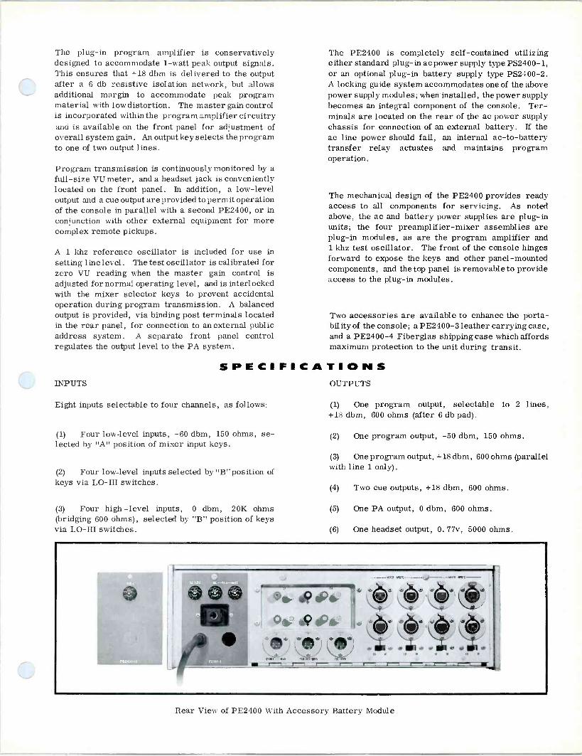
The plug-in program amplifier is conservatively designed to accommodate 1 -watt peak output signals. This ensures that +18 dbm is delivered to the output after a 6 db resistive isolation network, but allows additional margin to accommodate peak program material with low distortion. The master gain control is incorporated within the program amplifier circuitry and is available on the front panel for adjustment of overall system gain. An output key selects the program to one of two output lines.
Program transmission is continuously monitored by a full-size VU meter, and a headset jack is conveniently located on the front panel. In addition, a low-level output and a cue output are provided to permit operation of the console in parallel with a second PE2400, or in conjunction with other external equipment for more complex remote pickups.
A 1 khz reference oscillator is included for use in setting line level. The test oscillator is calibrated for zero VU reading when the master gain control is adjusted for normal operating level, and is interlocked with the mixer selector keys to prevent accidental operation during program transmission. A balanced output is provided, via binding post terminals located in the rear panel, for connection to an external public address system. A separate front panel control regulates the output level to the PA system.
SPECIFICA INPUTS
Eight inputs selectable to four channels, as follows:
(1) Four low-level inputs, -60 dbm, 150 ohms, se- lected by "A" position of mixer input keys.
(2) Four low-level inputs selected by "B"position of keys via LO -HI switches.
(3) Four high -level inputs, 0 dbm, 20K ohms (bridging 600 ohms), selected by "B" position of keys via LO -HI switches.
The PE2400 is completely self-contained utilizing either standard plug-in ac power supply type PS2400-1, or an optional plug-in battery supply type PS2400-2. A locking guide system accommodates one of the above power supply modules; when installed, the power supply becomes an integral component of the console. Ter- minals are located on the rear of the ac power supply chassis for connection of an external battery. If the ac line power should fail, an internal ac -to -battery transfer relay actuates and maintains program operation.
The mechanical design of the PE2400 provides ready access to all components for servicing. As noted above, the ac and battery power supplies are plug-in units; the four preamplifier -mixer assemblies are plug-in modules, as are the program amplifier and 1 khz test oscillator. The front of the console hinges forward to expose the keys and other panel -mounted components, and the top panel is removable to provide access to the plug-in modules.
Two accessories are available to enhance the porta- bility of the console; a PE2400-3 leather carrying case, and a PE2400-4 Fiberglas shipping case which affords maximum protection to the unit during transit.
T I O N S OUTPUTS
(1) One program output, selectable to 2 lines, +18 dbm, 600 ohms (after 6 db pad).
(2) One program output, -50 dbm, 150 ohms.
(3) One program output, +18 dbm, 600 ohms (parallel with line 1 only).
(4)
(5)
(6)
Two cue outputs, +18 dbm, 600 ohms.
One PA output, 0 dbm, 600 ohms.
One headset output, 0. 77v, 5000 ohms.
Rear View of PE2400 With Accessory Battery Module

GAIN (±1 db) input, for normal attenuator settings and +18 dbm output.
(1) Microphone input to program output; 110 db. POWER REQUIREMENTS
(2) Microphone input to low-level (parallel) out- put; 42 db. (1) 105v to 125v or 210v to 250v ac, 50/60 hz, single
phase, 20va (with PS2400-1 ac power module supplied). (3)
(4)
Microphone input to cue output; 110 db.
Microphone input to PA output; 92 db.
High-level input to program output; 50 db.
(2) Internal or external 36 vdc (PS2400-2 battery power module provides 40 hrs of program operation).
(5) AMBIENT TEMPERATURE
(1) AC operation; -18° C to 65° C.
(2) Internal battery operation; 5° C to 45° C.
OVERALL DIMENSIONS
(1) Less carrying cases; 5-1/2 in. high, 12-11/16 in. (2) Within ±1. 5 db, 30 hz to 20 khz. deep, 17-1/2 in. wide.
FREQUENCY RESPONSE (ref 1 khz)
For any input to any output at normal attenuator settings:
(1) Within ±1 db, 50 hz to 15 khz.
NOISE:
(1) Relative input noise from any preamp, -122 dbm, measured over 10 hz to 100 khz bandwidth.
HARMONIC DISTORTION
Less than 0. 5%, 50 hz to 15 khz, with -60 dbm level to a microphone input or 0 dbm level to a high level
(2) Leather carrying case; 19 in. high, 14 in. deep, 19-1/2 in. wide.
(3) Fiberglas shipping case; 10 in. high, 14 in. deep, 19-1/4 in. wide.
WEIGHT
(1) With ac power module, 25 lb.
(2) With battery power module, 25 lb.
ORDERING INFORMATION ORDER: PE2400 Portable Audio Console complete with ac power module type PS2400-1.
Optional Accessories:
PS2400-2 Battery power supply module com- plete with battery.
PE2400-3 Leather carrying case.
PE2400-4 Fiberglas shipping case.
McCurdy Radio Industries reserves the right, without notice, to make such changes in equipment, design, specifications, or components as progress in engineering
or manufacturing techniques may warrant to improve the performance of the product.

CS2:0 series
intercom systems
Q

description
The McCurdy Series 9000 intercom systems offer application flexibility and performance reliability to satisfy the most stringent broadcast and professional requirements.
Complete intercom systems, including optional equip- ment such as key panels, microphones and speakers, can be supplied by McCurdy Radio Industries.
Solid-state, balanced crosspoints for reliable switching. All crosspoints are supplied in 10 x 10 and 20 x 20 matrices.
Two basic input/output configurations, 10 x 10 and 20 x 20. Custom units and larger configurations on request.
On 10 x 10 and one type of 20 x 20 configuration, all circuit connections are made to standard rear - mounted connectors. The 20 x 20 is also available with terminal blocks provided for circuit connections.
Each input amplifier may be switched to accommo- date carbon microphone, dynamic microphone or line input.
Automatic gain control circuitry for input amplifier which is easily strapped in or out of circuit.
Customer insert capability between input amplifier and matrix (e.g. jackfield).
Full 3 Watt output available into 8 or 600 ohms (+35dBm, 600 ohms) and an auxiliary line output at +18dBm, 600 ohms.
Output amplifier muting circuit providing full or partial mute.
Silicon solid-state circuitry of proven reliability used throughout. Inexpensive, dual, plug-in crosspoints provided. Many customizing, extra -cost options available, such as: - Partial crosspoint mute - Crosspoint inhibit control - Crosspoint tally control - Crosspoint delegation control
AP276 INTERCOM PREAMPLIFIER AND MATRIX CROSSPOINT CARD The AP276 may be switched to accommodate a carbon microphone, dynamic microphone or line input. To accommodate wide variations in input level, the automatic gain control section may be activated by changing jumper positions on the circuit board (no soldering required). The ten plug-in crosspoints as- sociated with each input amplifier, which determine the audio routing from input to output, are contained in the AP276. In systems larger than 10 x 10, such as 20 x 20, 30 x 30 or larger custom units, only the first matrix card in any input line is provided with an input preamplifier. All other cards in each bus contain only crosspoints and controlling logic.
AM278 AND AM478T OUTPUT AMPLIFIER CARDS
Two different output arrangements are possible with this series of output amplifiers.
The standard AM478T consists of two identical amplifiers, each featuring a +18dBm, 600 ohm, active -balanced line output and an isolated transformer -coupled 3 Watt, 8 or 600 ohm output. Both outputs from each amplifier are individually adjustable.
The optional AM278 consists of two amplifiers, each having an active -balanced +18dBm, 600 ohm, line output. Other optional output amplifier configurations, for use in larger custom systems, are also available.
POWER SUPPLY A fully regulated +15 Volt power supply is provided as standard equipment with each intercom system. The quantity of power supplies will depend upon the current requirements of the particular intercom system. On custom systems larger than 20 x 20, a separate +4 Volt power supply is required, in addition to the +15 Volt supplies.

functional, 20 x 20
RPYT LEVELS
ne» MIC. - -waT,[l0n .101226000 112713 I-
CAM - -10423.500 I r - r IRIm> OYx NC/LK I,º191
64.32191 CAILL MO R /i101 .3xlM:.-
?(:,07,
(91
2
Q ̀ uol x1ºI;
[
u1n> @ 22F !
Dol ,]xI91> n (
Y191
YlE1> Q
`<
C JMroI N,>SN91> p `
r ( 12191 I 021E1>
3
,N1191> --Tb-« I T J 1ºI
e
[4211e1> 4p
`].Eppo-11
3,NI191> Y eF L
r une), @ ¿!c- L N101 ,3511ºI>----p-<F [
In
2lºI rr 1,2 119)>- <F
L ,3x191> 4 `
L 2191
9
1 L21N1>-
,411111 F F
iWl }xI91 j
MMJL,E 0 1=I,i
1O
[u11e1> orN `I C!
}x191>-----tMe N0 L 3 rot
11C/UNE 1,311e1> 085
L2191
<4Ì
Q [3
3 1101
Sx1R CA1aj
n> 12
[34.35121>
Lzl 4
CF
QNol ( z1N
yz191 I.211131>
Q C - S1101
Il
64.331 91> @ <F-,
.f ln> Q
(ºI Lzl F^
L.,>xl9t> l<
r LEM>'
)51131>
Q 1=
éxF AI
Ium
FRAME I
Onl 19C/LINE I /0 ,2191 r 42Nelj 4<
0 I 3x191j n (
REAR NIEL CONNECTONS Y
L
INPUT SHIELDS
GROUNDED AT T SO9L0B PI114 9 lO O
20. JI NPOUGH OC 0 STRIsuTION 0W01
EACH OUTPUT CONTAINSECT
REAR
PANEL
áÌf
TWISTED PAIRS
FRAC)
',Tel_ xPo
\>1- a,6 B -- xPl
- - [PJ ,P9 X. xP Ms
xP21T xV0
i 1
,é VI xn -------------------- xn xn IM [P
ÌI I¢ln / >
Se 06
3 --------- ----- --- 139 zJ L-
I 1 1
36 » Se 40 ' 4I .z ] 1 J I ,P1D2
V2 º 5 6 7 4 9 l0 II 12
1' J2
I
,e <
36 31 3e 39 10 N 4E 43 44 .y
1 [Pxu
JS
S.6 1=
4 3 6 B º 0 I J3
I
18
6 31 3B 33 0 I 2 .3 4
xPg4 L.s J
s>e ] S 6 2 . 9 IO 1I 12IIJ
I I, -
36 3T 36
I ]91 40 2 3 44 NI
I NOS
' J! >
x6 s
3 c e 9 O 121 ' J6
1 1 ,e
]6 31 ]s 19N1 40 .1 42 a
xRos 0> » J6 ¿12I ;¿a
3 6 1 6 5 10 U ' I J6
I 1s
w 31 3e 39 0 a 2 u 4. n)
Mvo1 s 3 5 6 , c º lo II ' 1
J,
1 ,s
Sc n 39 39aSl 40 .1 sz 3
9108 V
e
] 4 S e , 9 IO II 131 '
I 2°
36 31 3e 39 40 M 2 J 1 *1
1.>ñ3 IaeO 4 5 6 7 6 º ro ' 1N
I
w 3, !. 39 10 u 43 + .a
16
410
x6 °
KW 413.34
JO JO
4M JIO
17.18
A 41620
Jp 2022
JIO
S23,21 VV2xa J10
r2E2 JIO
¡.2930I JU
1JIOe1 1
16.¢
1
JIO
1
I
,e
=0.M JIO
V4M PD AD
vR.le JP V =¡O.YY
A ,2).24
JIO
JIOi25,26 1 J
IOYT.n II
JP
I
_.
1[Pn .3,>, ><
66 e
] !21 6 6 º D I Jx 36 37 3. 39 40 .2 .] 3
[vR P¢
JIz
1 36 e
3 . 5 c T 9 lo n 121 ' J¢
1 1e
36 36 3 .1 42 l 45I
I[n3 ]
Jn 3 4 5 c 7 3 9 10 n Jn
1
1
,e
3s 37 38 ]4 +0 J1 2 0 + 491
1 xnM
1..3 ""'
4 ] 6 s º IO R 1z ' I n1
,e
36 n )s 39 49 41 a 43 4
[Pa
a6
6 1 3 9 10 M
=1 j' 1
I Ta
36 37 ]e 39 40 « 4: .) 45I
1
wM > 3 6 e º 0 ' JN
1 1
1e
M !2 x
e
39 .o az 3
1,1 > E
! 6 B º 0 ' I JR
I,e !6 31 3e 39 40 .I 1! ,
PIP > °
z
3 S 6 T B º 10 II ' JP
1 1s
36 31 31
J
39 10 . .3 a.
x1. » JR < > \"t------ 3,6e ---- c
--_-- 9
-- O
JN
2P 1 ' 1 1e
y6 ---- 3, 3B --- 39 o n 4Y 3 1!1
1 ,nn
--r >
20
I/2 FRAME
CARO
0r1fMM -43
-
r --
LL
L -
------- 8.12
JI
3
-4114763-
U
1
I
I
e; 13.1.
2
I311
s
N
I
79 V
I
I
v,J S
-N J3
J2 J2
1111
-
VM
--
oe
RU
ss
-
------ J4
J2 ]9,1 ITt
-
a
M
-
A
E9
}e
542D J5
/L1 .13
1161
-24471117-
-
1U37.
c
M.22
a
A A11 IT1
AS
-
--
3
-
Yx26
a
t JI
IHI - Js
13
a9Eov
-
4...4.,...,30I x
O.
/Ll9,N I3,1
-
s
U
- i9
}º
A
11=12O.
JS 11N
N31 -3,44787-
U V V 11.13
-
ea
/03A, "NI'
a
IO
IJ2D
I
I
L
E9
37.93
- - -
42¢ JI
O.
4ARE 101 - Nor-
[,U
e
-
V,y 312
6
J 131/
e
A¢
V
-
3.
I
)}
p.N A
-
J O 1 1131
-
®
,..
neT-
ILU
-,.,
ego J
Q
J)AA1 I3T
©
-
E9
v4 A
JAq9 IN1
_
tU
N
a AN 13,3
_
e ©
_
,I
iº
}º
- 423.24
J1
G
A10 R161
-424787- A'
U V
J N
V N.13
°
-
-- 2x26
a
O.
/ AN AISTIr
Re
V Zrs
-,
I
1
1
--- eau.,
J9
AT
AR9 - 11 _
-
4I0
9i
yU
11
Ì\R20/
1
ó4-isr,»
JI -.
--
N41 1311
_
-
,1
I
I
_
¡
/
.iióli*,sooA.
131 s,R
11321
I
1
1 21
16
()21 161 1]21
I
1 21 1631 13 1 1
I
21 1]21 16JT 1!2) 1i21 I121 S31 (Stl (J21 l J21 IIiL ( 21 (321
I 142)
1 1 A rm rm r0 _. TO -- -_ .-CPA rr 3131.772N 400
1131 1331 13)1
«50 1331
49.}0 1331
250 1331
49.50 1331
4950 4920 1331
1-1 M50 1331
49}0 1331
13
49,50 1331
450 1331
49}0 1331
la
49.50 1331
I3,50 1331
1-1 Ie
*50 1331
19
4250 1331
20
ARNE 2
A PANEL
ION
PRANE 3
NINGED
PR2 i1E
FRONT VIEW
PRE- AMAS WR11 x-1101114 NPUTS 1121101123 m
10 WTMS I TNROUGH IO
7 X- POINTS ONLY
INPUTS 1 111101161 20 10 OOTPUT, O 1MIOI211 20
POR OETAIYEO
0-
TAILED
1. SE[ U2W6 N 9200/3-I
OUTPUT AMIN P9-1 n-2
REAR VIEW
Ù1ii1FitÛ1 L J
Ui 49V 49 31 53
V v vv
OR YPE
MnTINO01 WT'CSNNON 0050-7
- - TM OE TAILED
sffNDW6Ax C-92O0J!-I
R<Nf z
\ x701- 0710$
VV ) a v
17 43 5
V V
53 a >º
v v eSVi
._
I 1
21 39 0 H A
. H
4/31 50 1N CONNECTOR
TIPMAL x -POINT roCONNECTOR WIRING
LEGEND
NORMALLY Off, 9X100420 ON x-30180.
4, NORMALLY oN, 3MTCNEO OAP x-101111
PERMANENTLY ON 2 -POINT.
w.i NORMALLY OFF. SMTCNED ON (Y RECEIVER/
tg 1404321117 09.2*1TCHE1 TO PARTIAL
DELEGATION CONTROLLED N -POINT
11611617 CONTROLLED 21301110
NOTES
1 LEVELS
01Sni SNLVE 23 ARE
INc LEVELS LEVELS
ARE IOea
E CN x-101117 HAS A CONNECTOR
3.
.-<! INDICATED POINT CONTRM. IS ..,1. 640.
' RO 0.20 INTERCOM COMES ALL x -POINTS SUPPLIED.
INPUTS044 N1C .1.112 ARE
AMPLIFIERS ' WITHIN THE INPUT
AM
OUTPUT SHIELDS OROUNOEO a SHIELD BU
PIN LS CONNECTORS
INUT24 1l EE D R DC UT DWG

specifications
All levels are nominal, unless otherwise specified. Test levels are given in brackets.
INPUT LEVELS: (with AGC section out) 1) Dynamic microphone; -60dBm (-50dBm), 150
ohms. -25dBm, maximum. 2) Carbon microphone: -25dBm (-15dBm), 50
ohms. OdBm, maximum. 3) Line, bridging; OdBm (+10dBm), 600 ohms.
+18dBm, maximum.
INPUT LEVELS: (with AGC section in) Dynamic microphone, for 2dB, maximum, output change; -60 to -30dBm, 150 ohms.
INPUT IMPEDANCE: At least ten times source impedance.
INTERSTAGE LEVEL: At output of AP276 with AGC section out; -10dBm (OdBm), 600 ohm, terminated bus. +10dBm maximum.
OUTPUT LEVELS: With AM478T output amplifier. 1) Line output; +18dBm, 600 ohms, maximum. 2) Main output; 3 Watts, 8 ohms or +35dBm, 600
ohms, maximum.
FREQUENCY RESPONSE: +1dB, -2dB, 100 Hz to 10 kHz
DISTORTION: 1% maximum, 150 Hz to 10 kHz at rated output.
SIGNAL TO NOISE RATIO: 80dB below rated output, minimum.
EQUIVALENT INPUT NOISE: Better than -115 dBm, unweighted, typically better than -120 dBm.
CROSSPOINT DRIVER SINK CURRENT: 50mA, maximum
POWER REQUIREMENTS: 1) CS9100, 10 x 10 matrix; 117 Volt (230 Volt optional),
50/60 Hz, 150 VA 2) CS9200, 20 x 20 matrix; 117 Volt (230 Volt optional),
50/60 Hz, 300 VA
DIMENSIONS: 1) CS9100, 10 x 10 matrix; 5.25 in. (133.4 mm) high, 19
in. (482.6 mm) wide, 14 in. (355.6 mm) deep, excluding mating connectors.
2) CS9200, 20 x 20 matrix; 15.75 in. (400 mm) high, 19 in. (482.6 mm) wide, 14 in. (355.6 mm) deep, excluding mating connectors.
3) CS9220, 20 x 20 matrix; Same as CS9200, except that terminal blocks are supplied on rack mounting bracket to be mounted behind the intercom frames.

- . ..
V: 8 ej 1 o o= z
ti
: 1
» 8 eg I i
e : e e 2 2 2 2 2 1
el e
I
- : * " 1
.I1
e
' '21> 8
e I -:1. " ' " "
o
1 V 11 1
- - - - *.:
8
g g Zill " ' " " o
%; g Ul" :
o i
1
I a,
'-.1
. __-
-
.
--_.11
'''
'
3, ,..,
. - 7.
11
.2- T
i,
. i
.-,-. !.
.e.
,,:z
:,, e 5 ,
.1,
; g F, ,,,,
1
1
t
e
:.-
-.-iiräg
ä
Aiki
.
!,
g
3
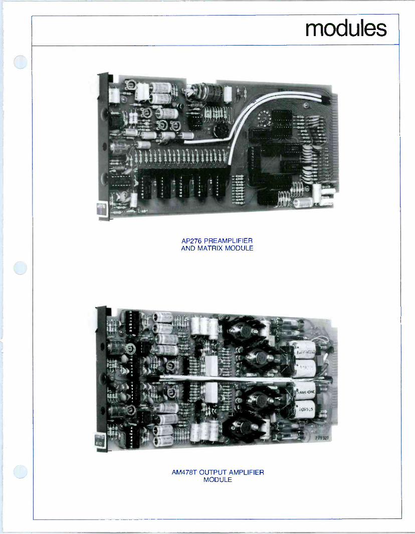
modules
t
7:3011104111Pli11iI2111 1- S1. 1 5, 111a :::::l:::111::: NIS l,t. . . . . . . . . . .
'41 401P
AP276 PREAMPLIFIER AND MATRIX MODULE
AM478T OUTPUT AMPLIFIER MODULE

ordering information
CS9100 10 x 10 intercom system complete with input amplifiers, matrix, output amplifiers and power supply for 117V ac operation. All circuit connections on rear panel connectors.
CS9100/230 Same as CS9100 except supplied for operation on 230 Volt ac power.
CS9200 20 x 20 intercom system complete with input amplifiers, matrix, output amplifiers and power supply for 117V ac operation. All circuit connections on rear panel connectors.
CS9200/230 Same as CS9200 except supplied for operation on 230 Volt ac power.
CS9220 20 x 20 intercom system complete with Input amplifiers, matrix, output amplifiers and power supply for 117V ac operation. All circuit connections on terminal blocks, mounted on bracket behind intercom frame.
CS9220/230 Same as CS9220 except supplied for operation on 230 Volt ac power.
Custom key panels, designed to suit the control requirements of the intercom system, available on request.
For information on larger systems, options available, or for engineering assistance and application information, contact the nearest McCurdy Radio Industries office.
CS9100, rear frame layout
178 Printed in Canada
McCURDY RADIO INDUSTRIES LIMITED 108 CARNFORTH ROAD. TORONTO. ONTARIO M4A 2L4 (416) 751-6262, TELEX 06-963533, TWX 610-492-1373
McCURDY RADIO INDUSTRIES INC. UNITED STATES HEAD OFFICE
1711 CARMEN DRIVE, ELK GROVE VILLAGE, ILLINOIS 60007, (312) 640-7077, TWX 910-222-0436 EAST COAST OFFICE
223 WEST SADDLE RIVER ROAD. SADDLE RIVER, N.J. 07458, (201) 327-0750, TWX 710-988-2254 BUFFALO WAREHOUSE
1051 CLINTON STREET, BUFFALO, N.Y. 14206, DIRECT LINE TO TORONTO PLANT (716) 854-6700. TWX 610-492-1373
McCurdy Radio Industries reserves the right, without notice to make such changes in equipment, design, specifications, or components as progress in engineering or manufacturing techniques may warrant to improve the performance of the product.

DESCRIPTION The CS7000 Series Intercom is designed to meet the most sophisticated intercom requirements of professional systems, such as radio and TV broadcast stations, industrial, and commercial applications .
The CS7000 is completely solid-state, utilizing compact modules that plug into prewired 19 -inch rack frames. A basic system comprises a switching matrix, input and output amplifiers, and a power supply (with separate frame) . McCurdy Radio Industries can also supply key panels, microphones, and speakers as extra - cost options to complete the facility .
Three standard configurations are avail- able in the CS7000 series: 10 x 10 (up to 10 inputs and 10 outputs), 18 x 20, and 36 x 40. These basic systems are cal- culated to provide the maximum in ver- satility without the need for customizing. Further, any of the above systems can be assembled iñitially with less than its full complement of modules, with an eye to future completion merely by addition of the switching modules and amplifiers.
SMX12 SWITCHING MATRIX
The heart of the system is the crosspoint switching matrix which determines the audio routing from any input source to the desired destination. ($efer to the Intercom Functional Diagram) .
At each crosspoint of the matrix, where communication is desired on an on -off basis, an SM11 reed relay circuit is in- stalled. The relay is activated by 24 volts do applied from a key panel. The reed relays are installed on SMX12 Switching Matrix cards, each of which holds up to six SM11's and plugs into a 19 -inch prewired frame.
SECTION:
Intercoms Iss. 1; May 170
SERIES INTERCOM SYSTEMS
%.__
11111fIlIlIIlIIlIlIIlI 1 i
11101
MI 1
III
I
11111
aì:
HI '
MCCURDY RADIO INDUSTRIES LIMITED 108 CARNFORTH ROAD o TORONTO 16 O CANADA
MCCURDY RADIO INDUSTRIES INCORPORATED 1051 CLINTON STREET G BUFFALO o N.Y. 14206
I(416) 751-6262 TELEX 02-21660
(716) 854-6700

In some areas a continuous connection may be required between two stations, in which case the crosspoint is simple a 15,000 -ohm resistor which provides the re- quired isolation. Keys are not required for these cross - points .
Isolation in the switching matrix, and privacy, are main- tained by the fact that non -energized relays present an open circuit. In this manner, crosstalk in the relay crosspoints is better than 60 dB. In addition, the McCurdy CP7101 Key Panels (optional) provide extra contacts for operation of muting circuits in areas where there is danger of acoustical feedback.
AP272 INPUT AMPLIFIER
An advanced feature of the CS7000 is the unique ability to handle carbon microphone, dynamic microphone, or line level inputs with a single type of input amplifier (AP272).
Also, the addition of an AP272-1 Compressor Module (optional) to the AP272 will compensate for wide varia- tions in input level. The AP272-1 is an easily -installed plug -on module.
CARBON MIC, DYNAMIC MIC OR LINE (AS STRAPPED)°
INPUT AMPL S TYPE AP 272
O
A 1 10
>> >>
K
CCT N2
OUTPUT AMPLS TYPE AM 273
MUTING CTL-RLY, PART OF AMPL
O O
OUTPUTS +33 DBM (MAX) 2 WATTS 811, 15011,60012
K
10 VVV/ O 0 O
O O O O
NOTE
MARK WITH X WHERE CROSSPOINTS ARE REQUIRED
UNIT SHOWN IS BASIC 10 X10 SYSTEM
Typical Functional for 10 x 10 Intercom

AM273 OUTPUT AMPLIFIER
The AM273 Output Amplifier provides a full 2 watts out- put to an 8 -ohm, 150 -ohm, or 600 -ohm load (150 ohms requires strapping on amplifier card). A plug-in muting relay is optional, but internal wiring for the relay is completed.
POWER SUPPLY
One power supply provides sufficient power to operate the entire system since the supply rating is chosen according to the needs of the system.
MECHANICAL DETAILS
The input amplifier and matrix circuits are built on glass -epoxy printed -circuit cards attached to extruded aluminum front panels. The panels are covered with dark blue plexiglass escutcheons. These modules are 53/64 in. wide and twenty modules can be accommodated in one FR904 Card Mounting Frame.
The output amplifiers are built on printed boards and are constructed similarly to the input amplifiers, except that they are 1-11/16 in. wide and ten can be fitted in one frame.
The power supply mounts in a separate frame below the output amplifiers, and is covered by a blank panel.
Blank modules are available to fill up unused spaces in each frame. The frames may be mounted in a standard 19 -inch rack or stacked as a separate assembly.
Pertinent dimensions are shown in the Outline Diagrams for complete 10 x 10, 18 x 20, and 36 x 40 systems. These also show the quantities of modules required in each case.
I4
3 2
3-
NOTES I. SMX 12 ; MAX 20 PER FRAME ( 12 0 CROSSPOINTS)
AP 272; MAX 20 PER FRAME AM 273 ; MAX IO PER FRAME
2. QUANTITIES SHOWN ARE MAXIMUM FOR EACH SYSTEM
19*
31* 2 5- 4 L__
IÓ x AIP12172
I I I I I I II I I l M 7 x1 SMX 12
Ì (100 ROSS
10 AM273 I I I
BLANK PANEL
POWER SUPPLY
18 AP272
60 x SMX 12
360 CROSSPOINTS
(3 FRAI MES)
BLANK PANEL
20)X AM273
171.' (2 FRAMES) 2
10 INPUTS - 10 OUTPUTS (10 x 10)
BLANK PANEL
POWER SUPPLY
294
18 INPUTS- 20 OUTPUTS (18 x 20)
t
36 X
AP272 (2 FRAMES)
BLANK PANEL
240 x
SMX 12
1440 CROSSPOINTS
(12 FRAMES)
z BLANK PANEL
40 x AM273 (4 FRAMES)
BLANK PANEL
BLANK PANEL
POWER SUPPLY
36 INPUTS -40 OUTPUTS (36x 40)
Frame Layouts and Dimensions for Basic CS7000 Intercoms

SPECIFICATIONS INPUT LEVELS and SOURCE IMPEDANCES
(1) Dynamic Mic; -50 dBm, 150 ohms. (2) Carbon Mic; -15 dBm, 50 ohms. (3) Line; 0 dBm, 600 ohms.
OUTPUT LEVEL
+33 dBm (2 watts) .
LOAD IMPEDANCES
8 ohms or 600 ohms (150 ohms available by strapping on output amplifier card) .
FREQUENCY RESPONSE
Within 5 dB 100 Hz to 10 kHz.
STANDARD EQUIPMENT
DISTORTION
Less than 2% 100 Hz to 10 kHz at rated output level.
SIGNAL-TO-NOISE
60 dB below -50 dBm input at full rated output.
CROSSTALK
-60 dB 100 Hz to 10 kHz at normal operating levels.
POWER REQUIREMENTS
117v ac, 50/60 Hz: (1) 10 x 10; 220 va. (2) 18 x 20; 300 va. (3) 36 x 40; 450 va.
ORDERING INFORMATION
(A) CS7000 Intercom in 10 x 10, 18 x 20, or 36 x 40 con- figuration. McCurdy Radio Industries will provide, on request, a Functional Diagram for indication of inputs, outputs, and crosspoints required.
(B) SMX 12 Switching Matrix. Up to six SM11 Switching Modules per SMX12 card. Available with 15,000 -ohm resistors for continuous crosspoints.
(C) AP272 Preamplifier for line, carbon mic, or dynamic mic. Specify when ordering.
(D) AM273 2W Output Amplifier for 8 -ohm, 150 -ohm, or 600 -ohm output. Specify when ordering.
(E) Power Supply.
,OPTIONAL EQUIPMENT
(A) CP7101 Key Panel. The standard CP7101 contains five lever keys and is designed for flush -mounting in a desk top or panel cutout. The keys are 3 -position (center OFF) and may be locking (L) , non -locking (NL) , or L -NL. Custom panels may be provided as required.
(B) LS7104 Speaker. The LS7104 is an 8 -ohm enclosed speaker designed for placement on a desk. A volume control is included.
(C) Microphone Kit.
CP7101 Control Panel with CP7101-1 Recessed Panel
(D) Power Amplifiers for special paging applications are available as required.
(E) AM272-1 Compressor Module plugs onto AP272 Pre- amplifier.
(F) Muting Relay for AM273.
(G) SA10410 or SA10420 Equipment Rack.
Custom versions of the CS7000 Intercom may be engineered on request to suit any reasonable requirement.
McCurdy Radio Industries reserves the right, without notice, to make such changes in equipment, design, specifications, or components as progress in engineering
or manufacturing techniques may warrant to improve the performance of the product.

235 235 series
phono preamplifiers
GAIN
TRIM
J1 ^
HI-FREI] TRIM .'
AT 235
GAIN
TRIM
HIFREQ TRIM
MeY AT 235
Zeir LEFT SA 236
UgCUffiCder
description AT235 PHONO PREAMPLIFIER
The McCurdy AT235 is a professional quality magnetic cartridge preamplifier primarily designed for broadcast applications. All components are mounted on a glass -epoxy printed circuit board which plugs into an SA10072 single unit frame, an SA236 preamplifier package or an FR904 universal frame. All low-level circuitry is contained within a shielded enclosure. The input connections from the cartridge are made to a front panel mounted phono connector with all other connec- tions being made to a PC edge connector.
Equalization is within +0.5 dB of RIAA Equalization curve.
The preamplifier input is matched to all popular magnetic cartridges. No resistor changes or other compensations are necessary.
Output levels ranging from -20 dBm to +8 dBm (nominal) are available by changing the amount of feedback applied around the amplifier.
The gain of the preamplifier is changed by varying the feedback resistor mounted on the PC edge connector.
Roll -off frequencies of 5 kHz, 7 kHz, 10 kHz and 12 kHz are available for improved reproduction of noisy records.
The roll -off is accomplished by FET switching, therefore, eliminating external audio runs for this function.
Six balanced outputs are provided, two 600 ohm, two 150 ohm, one direct and one combining, which gives a mono output from a pair of AT235's.
Front panel mounted Gain Trim and High Frequency Trim controls are provided for exact level matching in stereo applications.
The low noise and distortion characteristics of the preamplifier will meet the most critical applications.
The wide dynamic range available, in excess of 40 dB, will accommodate the output from any recording.
SA236 PHONO PREAMPLIFIER PACKAGES McCurdy Radio Industries offers two phono preamplifier packages, one monaural and one stereophonic, specifi- cally designed for broadcast applications. Both incorpo- rate the AT235 phono preamplifier and a fully regulated and shielded power supply.
Six output levels from -20 dBm to +8 dBm (nominal) are available, selectable by a front panel mounted switch.
Preamplifier outputs are wired to a rear panel mounted screw terminal strip.
The SA236 is supplied with the 600 output wired. The 150 ohm and direct outputs are available on the PC edge connector.
On stereo units, a 600 ohm mono output is provided. The 5 KHz roll -off control is wired to the output
terminal strip. The other roll -off frequencies are available on the PC edge connector.
The SA236 is normally wired for operation on 117Volt 50/60 Hz power. Wiring for operation on 230 Volt 50/60 Hz is available as an option.
specifications GAIN: 24 dB to 52 dB, at 1 kHz, determined by value of external feedback resistor. INPUT LEVEL: 5 mV nominal into 47K ohms resistive source. (Equivalent to - 44 dBm at 1 kHz, into 600 ohms, terminated). Maximum input level at 1 kHz, 700 mV into 47K ohms resistive source. (Equivalent to -3 dBm into 600 ohms, terminated) depending on gain strapping. INPUT IMPEDANCE: 47000 ohms.
OUTPUT LEVEL: (for 5 mV input) -20 dBm to +8 dBm (nominal) into 600 ohm outputs, +24 dBm maximum. +30 dBm maximum on direct output. OUTPUT IMPEDANCE: 600 ohms or 150 ohms, balanced. LOAD IMPEDANCE: 600 ohms or 150 ohms, balanced. DYNAMIC RANGE: greater than 40 dB, depending on gain strapping.
FREQUENCY RESPONSE: Within + 0.5 dB of RIAA equalization curve, 30 Hz to 15 kHz.
ROLL -OFF: Externally selectable roll off frequencies of 5 kHz, 7 kHz, 10 kHz and 12 kHz.
OUTPUT NOISE LEVEL: Better than -82 dBm for 30 dB gain at 1 kHz, (10 Hz to 100 kHz), (Equivalent to -112 dBm input noise). DISTORTION: 0.25% maximum from 30 Hz to 15 kHz, at 10 dB above nominal level, typically 0.1%. POWER REQUIREMENTS: AT235: 48 Volts DC at 50 mA, maximum. SA236: 117 Volts, 50/60 Hz (230 Volts optional), 13 VA.
OVERALL DIMENSIONS: AT235: 1.75 in (45mm) wide, 3 in (76mm) high 10.25 in (260mm) deep. SA236: 3.625 in (92mm) wide, 6.25 in (160mm) high, 12.375 in (315mm) deep.
AMBIENT TEMPERATURE: 0° to 55° C.

functionals
INPUT >-
INPUT L
I/P
INPUT R
GAIN TRIM
HI - FREQ TRIM
Al
AT2
A2
AT2
NOTE: A2 PROVIDED ON SA236 - P2 ONLY
ROLL -OFF
AT 235
0/P
FEEDBACK GAIN ADJUST
J600 n. OUTPUTS
J 150 SL OUTPUTS
DIRECT OUTPUT
SUM/CUE OUTPUT
5KHz > 7KHz
> I0KHz
> I2KHz
GAIN ADJUST L
ROLL -OFF
-20,-15,-10,-5, 0 OR +8dBm NOMINAL ( 600 11 OUTPUT )
35
POWER
SUPPLY
`
35
4 Z SA 236
OUTPUT L
5KHz ROLL -OFF L
II7V, 50/60Hz (230V OPTIONAL)
5KHz ROLL -OFF R
OUTPUT R
MONO/CUE GAIN ADJUST R
-20,-15,-10,-5, 0, OR +8dBm NOMINAL (60011 OUTPUT )

ordering information
AT235 Phono Preamplifier
SA236-P1 Mono Phono Preamplifier Package, includes one AT235 Phono Pre- amplifier.
SA236-P2 Stereo Phono Preamplifier Package, includes two AT235 Phono Pre- amplifiers.
SA236-P1 /230 Mono Phono Preamplifier package, for operation on 230 Volt 50/60 Hz power. Includes one AT235 Phono Pre- amplifier.
SA236-P2/230 Stereo Phono preamplifier package for operation on 230 Volt 50/60 Hz power. Includes two AT235 Phono Pre- amplifiers.
FR904 Equipment frame for ten AT235's
SA10072 Single mounting frame and connector for one AT235.
178 Printed In Canada
McCURDY RADIO INDUSTRIES LIMITED 108 CARNFORTH ROAD, TORONTO. ONTARIO M4A 2L4 (416) 751-6262. TELEX 06-963533, TWX 610-492-1373
McCURDY RADIO INDUSTRIES INC. UNITED STATES HEAD OFFICE
1711 CARMEN DRIVE, ELK GROVE VILLAGE, ILLINOIS 60007, (312) 640-7077, TWX 910-222-0436 EAST COAST OFFICE
223 WEST SADDLE RIVER ROAD. SADDLE RIVER, N . 07458, (201) 327-0750, TWX 710-988-2254 BUFFALO WAREHOUSE
1051 CLINTON STREET, BUFFALO, N.Y. 14206, DIRECT LINE TO TORONTO PLANT (716) 854-6700, TWX 610-492-1373
McCurdy Radio Industries reserves the right, without notice to make such changes in equipment, design, specifications, or components as progress in engineering or manufacturing techniques may warrant to improve the performance of the product.

mxese a 525 monitor amplifiers,
distribution amplifiers & systems
hMgCur D

description The McCurdy AM484 and AM487 are professional quality audio amplifiers designed primarily for use as monitor or distribution amplifiers in broadcast or commercial applications. Each amplifier, complete with power supply, is housed in a compact rigid, all -metal case designed for rack mounting in an FR905, 51/4 inch, equipment frame, which holds up to six amplifiers.
The McCurdy DA505 audio distribution system consists of a pre -wired FR905 equipment frame supplied with up to six AM487 amplifiers.
Fully protected, conservatively rated silicon solid- state circuitry
Cool running, all heat is radiated by a generously sized front -mounted heatsink
Mute circuit provides for remote -controlled partial muting of output and output muting during "power -up" to prevent undesirable transients
Gain control, power switch, fuse and LED indicators for power and mute conveniently mounted on the front panel
Two rear panel -mounted connectors provided for all circuit connections
Balanced, shielded, transformer -coupled input circuit with built-in connector -strapped loss pad
Multi -tapped isolating output transformer on AM487, direct 8 ohm transformerless output on AM484
Provision is made for separate feedback gain control, via a connector -mounted controlling resistor, of both the input and output amplifiers, allowing the optimum signal to noise ratio to be realized for any gain setting
Up to 75,600 ohm, output splits can be driven by the AM487 amplifiers
specifications INPUT LEVEL: -20 dBm, 600 ohms, balanced/unbalanced, nominal
INPUT IMPEDANCE: 6000 ohms
OUTPUT LEVEL: 20 Watts, 8 ohms. +43 dBm, 600 ohms (AM487 only)
OUTPUT IMPEDANCE: AM484, 8 ohms, AM487, 4, 8, 16, 150 or 600 ohms, strappable
OUTPUT SPLITS (AM487): 75 maximum, +18 dBm, 600 ohm on 16 ohm output.
OUTPUT SPLIT ISOLATION: (AM487): 55 dB, 30 Hz to 15 KHz
GAIN: 63 dB maximum. Variable by means of feedback resistors
FREQUENCY RESPONSE: + 0.5 dB, 30 Hz to 20 KHz
SIGNAL TO NOISE: 80 dB minimum for 0 dB input and 20 W output
DISTORTION: 0.25% maximum at 20 W output, 30 Hz to 20 KHz
MUTING: 10 dB partial mute (full mute available)
POWER REQUIREMENTS: 115V (230V optional), 50/60 Hz, 120 VA maximum (each amplifier)
DIMENSIONS: AM484 & AM487, 2.82 in. (72mm) wide, 4.82 in. (122mm) high, 14.2 in. 361 mm) deep DA505, 5.25 in. (134mm) high, 19 in. (482mm), 14.5 in. (375mm) deep
WEIGHT: AM484, 11 lbs. (5 kg) AM487, 13 lbs. (5.9 kg) DA505, frame only 20 lbs. (9.1 kg)

functional
Y U oaD 7)
wQ O O Ci c; O Li_ e Q
(OD
incD OD 'I- -VW- An
-/W- I-- Y Z I- ááa zó°ó
w Q w w
z á
....4v%\v...
c.9
A l.l1/4.JIJJ
w I- D 2
o e-
i
H D a z

INDIVIDUAL AM487 AMPLIFIER, TYPICAL OF AM484
ordering information AM484 Monitor Amplifier, 20 W, 8 ohm transformerless output, 115 V operation AM484/230 Monitor Amplifier, 20 W, 8 ohm transfor- merless output, 230 V operation AM487 Monitor/Distribution Amplifier, 20 W, trans- former output, 115 V operation
178
AM487/230 Monitor/Distribution Amplifier, 20 W, trans- former output, 230 V operation DA505 Prewired FR905 equipment frame to accept up to 6 six AM487 Amplifiers (Amplifiers to be ordered separately).
Printed in Canada
McCURDY RADIO INDUSTRIES LIMITED 108 CARNFORTH ROAD. TORONTO. ONTARIO M4A 2L4 (416) 751-6262, TELEX 06-963533, TWX 610-492-1373
McCURDY RADIO INDUSTRIES INC. UNITED STATES HEAD OFFICE
1711 CARMEN DRIVE, ELK GROVE VILLAGE, ILLINOIS 60007, (312) 640-7077, TWX 910-222-0436 EAST COAST OFFICE
223 WEST SADDLE RIVER ROAD, SADDLE RIVER, N . 07458, (201) 327-0750, TWX 710-988-2254 BUFFALO WAREHOUSE
1051 CLINTON STREET, BUFFALO, N.Y. 14206, DIRECT LINE TO TORONTO PLANT (716) 854-6700, TWX 610-492-1373
McCurdy Radio Industries reserves the right, without notice to make such changes in equipment, design, specifications, or components as progress in engineering or manufacturing techniques may warrant to improve the performance of the product.

úl3íl ALL -SILICON SOLID-STATE EQUALIZED PREAMPLIFIER
DESCRIPTION The AT131 is an all -silicon transistorized preamplifier designed for operation with monaural or stereophonic magnetic phono cartridges. In addition to raising the cartridge output to a usable signal level, the unit provides playback equali- zation in accordance with the RIAA standard reproducing curve. The pre- amplifier contains a roll -off filter that can be switched in when playing "noisy" retords. The input impedance is adjust- able to provide any required cartridge loading from 9,000 to 75,000 ohms. Equalization is independent of cartridge inductance.
An input gain control provides adjust- ment for cartridge output levels, and permits the AT131 to accommodate a wide recorded signal dynamic range. Careful circuit design and the use of close - tolerance components result in exceptionally accurate and consistent gain vs. response characteristics, and make the unit particularly suitable for use in pairs in stereo applications.
The AT131 is designed for mounting on, or close to, the turntable enclosure. The unit may be powered from a PS890 Power Supply or a similar source of
rectified 36 volts. The preamplifier contains a built-in do filter, and no primary filtering in the power supply is required as long as the line frequency is 50 cps or higher and full -wave rectification is employed.
MCCURDY RADIO INDUSTRIES LIMITED (416) 751-6262 108 CARNFORTH ROAD C TORONTO 16 C CANADA TELEX 02-21660
MCCURDY RADIO INDUSTRIES INCORPORATEDI (716) 854-6700 1051 CLINTON STREET G BUFFALO O N.Y. 14206

SPECIFICATIONS
TRANSDUCER GAIN (at 1 kc) 36 db± 1 db max (5 my input for -14 dbm f 1 db output)
FREQUENCY RESPONSE (see curve) Without roll -off filter: within ± 1 db of RIAA equalization curve, 30 cps to 15 kc
Roll -off greater than 14 db from RIAA response at 10 kc
OUTPUT NOISE LEVEL -72 dbm nominal, -64 dbm max, with 510 -ohm input termination
HARMONIC DISTORTION Less than 0.5% at +6 dbm output, 30 cps to 15 kc
INTERMODULATION DISTORTION (measured using a passive reverse RIAA network)
Less than 1% at a peak level of +9 dbm with the following frequencies mixed at 1:1 and 4:1 ratios;
(1) 60 cps and 2 kc (2) 60 cps and 7 kc (3) 60 cps and 12 kc
POWER OUTPUT +6 dbm, 30 cps to 15 kc
INPUT LEVELS 5 my nominal, 3v max
GAIN CONTROL RANGE 26 db ± 2 db
INPUT IMPEDANCE (variable) 9,000 ohms to 75,000 ohms
LOAD IMPEDANCE 150 ohms or 600 ohms, balanced or unbalanced
OUTPUT IMPEDANCE Less than 40 ohms at mid -frequency, with 150 -ohm load
POWER REQUIREMENTS 36 v dc at 20 ma; filtered or unfiltered
AMBIENT TEMPERATURE 55°C max
DIMENSIONS 1-11/16 in. wide, 3-1/16 in. high, 12-3/4 in. long
SHIPPING WEIGHT 3-1/4 lb
20
+10
Ddb
10
20
30
RIAA
ROLL OFF
20 30 50 100 C PS
IKC
Typical Frequency Response
IOKC 20KC
ORDERING INFORMATION Order AT131 Equalized Preamplifier; the RIAA/ROLL-OFF switch, escutcheon plate, cable, and plug are included at no extra cost.
ACCESSORIES (not supplied) One PS890 Power Supply, to supply sixAT131 Preamplifiers.
McCurdy Radio Industries reserves the right, without notice, to make such changes in equipment, design, specifications, or components as progress in engineering or manufacturing techniques may warrant to improve the performance of the product.

n2© SOLID --STATE
MICROPHONE PREAMPLIFIER
DESCRIPTION The AT240 is a silicon -transistorized microphone preamplifier designed for use in audio consoles or in any system requiring efficient amplification of low level inputs. The extremely low noise characteristic and wide input dynamic range of the AT240 permit amplification of inputs from -60 dbm to -20 dbm with negligible distortion. The high input impedance reduces source loading to a minimum, and the low output impedance provides maximum isolation against crosstalk when used in consoles or similar systems. The amplifier fre- quency response of 20 cps to 20 kc (within 0.5 db) is maintained over its entire range of operating levels.
The amplifier is compactly assembled using a contemporary dual glass -epoxy card design with precision gold-plated printed circuitry to ensure uniform high performance. Advanced design techniques, utilizing silicon transistors and high quality components, combine to produce a unit of exceptional per- formance and reliability. The AT240 can withstand abnormal signal conditions, such as excessive drive or overloading, with instant return to normal performance when the adverse conditions are removed.
Up to twelve AT240 modules can be accommodated in one SA10004 19 -inch rack mounting frame, and the complete assembly occupies only 1-3/4 inches
SA10004 Mounting Frame
vertically. When integrated within a system, these can be operated from a centralized PS874 power supply; when a separate rack installation is required, the SA10004 will accommodate up to ten AT240 modules and a PS876 power supply.
MCCURDY RADIO INDUSTRIES LIMITED (416) 751-6262
108 CARNFORTH ROAD C TORONTO 16 o CANADA TELEX 02-21660
MCCURDY RADIO INDUSTRIES INCORPORATED 1051 CLINTON STREET G BUFFALO a N.Y. 14206
(716) 854-6700
SPECIFICATIONS TRANSDUCER GAIN
40 db *1 db
FREQUENCY RESPONSE 20 cps to 20 kc, within 0.5 db (ref 1 kc)
RELATIVE INPUT NOISE -124 dbm, unweighted, measured over 10 cps to 100 kc bandwidth* -127 dbm, unweighted, measured over 10 cps to 20 kc bandwidth*
*Bandwidth specified at -3 db points.
HARMONIC DISTORTION Less than 0.25% at +20 dbm output, 50 cps to 20 kc Less than 0.5% at+20 dbm output, 20 cps to 20 kc
INPUT LEVELS -60 dbm nominal, -20 dbm max
OUTPUT LEVEL +20 dbm max
SOURCE IMPEDANCE 37.5 or 150 ohms balanced or unbalanced
INPUT IMPEDANCE Greater than 10 times source impedance
OUTPUT IMPEDANCE Approximately 25 ohms
LOAD IMPEDANCE 600 ohms unbalanced
POWER REQUIREMENTS 36v dc, 40 ma, from PS876 or equivalent
AMBIENT TEMPERATURE 650C max
OVERALL DIMENSIONS 1-3/16 in. wide, 1-3/4 in. high, 9-1/2 in. deep
WEIGHT 14 oz
ORDERING INFORMATION ORDER
AT240 Microphone Preamplifier
OPTIONAL ACCESSORIES 1. SA10004 Mounting Frame. 2. PS876 Power Supply.

3'22 SOLID-STATE UNIVERSAL
AUDIO AMPLIFIER
DESCRIPTION The AT242 is a plug- in, universal, solid-state amplifier designed for pro- fessional audio applications in the radio, television, and sound recording indus- tries. The state-of-the-art circuitry utilizing silicon transistors enables the amplifier to achieve an unusually high degree of flexibility and dependability.
The 1 -watt output capability, combined with the high gain and low input noise, allows the AT242 to be employed for low level microphone mixing, intermediate booster, or program output amplifier applications. The gain is strappable incrementally between 50 and 70 db and maintains a low input noise of -126 dbm.
The amplifier easily accommodates a wide dynamic range of input levels from -60 to -20 dbm. The distortion is ex- tremely low with a specified maximum of 0.25% up to +30 dbm for all frequen- cies between 50 hz and 20 khz.
The AT242 plugs into an SA10004 stan- dard 19- inch mounting frame which accommodates up to six units and occu- pies only 1-3/4 inches vertically. The unit requires 36 to 48 volts dc from a regulated source. The PS874 power supply provides 36 volts and is capable of supplying up to twelve AT242 ampli- fiers.
All conditional strapping is performed on the frame connector. The wiring con- figuration of this connector determines the amplifier function, which permits simple interchange of any amplifier within the system without regard to the specific mode of operation.
SA10004 Mounting Frame
The input is balanced and may be connected for 37.5, 150, or 600
ohms source impedance. The input transformer is carefully designed to reduce susceptibility to induced hum and is electrostatically and
magnetically shielded. The output is balanced and may be connected for 150 or 600 ohms load impedance. The output presents the low
impedance necessary for maximum isolation between resistive out- put splitter networks. Output short-circuit protection is incorporated to protect the output stage and power supply regulator components.
MCCURDY RADIO INDUSTRIES LIMITED TORONTO CANADA DANVERS MASS.

An internal active decoupling network gives the amplifier a high degree of isolation from the cen- tralized power supply and eliminates inter -system crosstalk. The amplifier interstage connections are returned to the frame connector to permit incorpora- tion of a variable gain control or special effects filter
for added flexibility.
The AT242 is unconditionally stable with or without input and output loads and will operate satisfactorily between balanced or unbalanced source and load circuits.
SPECIFICATIONS TRANSDUCER GAIN
50 to 70 db t 1 db; set by external resistor
FREQUENCY RESPONSE 20 hz to 20 khz within 0.5 db (ref 1 khz)
RELATIVE INPUT NOISE (unweighted) -123 dbm measured over 10 hz to 100 khz band- width* (noise power bandwidth 157 khz) -126 dbm measured over 10 hz to 20 khz band- width* (noise power bandwidth 31.4 khz)
* Bandwidth specified at -3 db points.
HARMONIC DISTORTION Less than 0.25% at +30 dbm output, 50 hz to 20 khz Less than 0.5% at +30 dbm output, 30 hz to 20 khz
IN TE RMODU LA TION DISTORTION Less than 0.5% at peak level of +33 dbm (2 watts) with the following frequencies mixed at 1:1 and 4:1 ratios: (1) 60 hz and 2 khz (2) 60 hz and 7 khz (3) 60 hz and 12 khz
INPUT LEVELS -60 dbm nom, -14 dbm max, with terminated input
OUTPUT LEVEL -10 dbm nom, +30 dbm max
SOURCE IMPEDANCE 37.5, 150, or 600 ohms, balanced or unbalanced
INPUT IMPEDANCE Greater than 10 times source impedance
LOAD IMPEDANCE 150 or 600 ohms, balanced or unbalanced
OUTPUT IMPEDANCE 1/3 of load impedance
POWER REQUIREMENT 36v to 48v do regulated, 120 ma, from PS874 (36v) or equivalent 48v supply
AMBIENT TEMPERATURE 0°C to 65°C
OVERALL DIMENSIONS 2- 1/2 in. wide, 1- 11/16 in. high, 9- 1/2 in. deep
WEIGHT 2 lb
ORDERING INFORMATION ORDER
AT242 Systems Amplifier
OPTIONAL ACCESSORY SA10004 Mounting Frame, to accommodate six amplifiers

N11242 Nú225
AUDIO TRANSFORMER MODULES
DESCRIPTION The MT244 and MT245 modules are high quality audio transformers intended primarily for use in audio consoles or other integrated audio systems. The MT244 is used in matching applications for levels between -22 dbm and +18 dbm; the input is strappable for 150 or 600 ohms and the output is fixed at 600 ohms. The MT245 is used for high -impedance bridging inputs of -10 dbm or greater, as in line input applications; the input is strappable for 5, 000 or 20, 000 ohms and the output is fixed at 600 ohms. Both transformers exhibit wide -band frequency response to ensure that the overall response of the system is maintained.
Each transformer is compactly as- sembled using a contemporary dual glass -epoxy card design with precision gold-plated printed circuitry to ensure uniform performance and maximum reliability. Internal electrostatic shield- ing is employed, and the heavy external shield provides maximum isolation from surrounding circuitry.
Up to twelve MT244 or MT245 modules can be accommodated in one SA10004 19 -inch rack mounting frame, and the complete assembly occupies only 1-3/4
SA10004 Mounting Frame
inches vertically. The transformers are mechanically interchangeable with the AT240 series of amplifiers, which permits versatility in selection of system facilities. Input and output wiring and transformer strapping are easily accomplished at the connectors on the rear of the frame.
McCURDY RADIO INDUSTRIES LIMITED (416) 751-6262
108 CARNFORTH ROAD O TORONTO 16 O CANADA TELEX 02-21660
MCCURDY RADIO INDUSTRIES INCORPORATEDI (716) 854-6700 1051 CLINTON STREET 0 BUFFALO 0 N.Y. 14206

SPECIFICATIONS FREQUENCY RESPONSE
20 cps to 20 kc, within 0.5 db (ref 1 kc)
POWER LEVELS MT244: -22 dbm to +18 dbm MT245: -10 dbm to+24 dbm
INPUT IMPEDANCES MT244: 150 or 600 ohms MT245: 5, 000 or 20, 000 ohms
OUTPUT IMPEDANCE 600 ohms
AMBIENT TEMPERATURE 65°C max
OVERALL DIMENSIONS 1-3/16 in. wide, 1-3/4 in. high, 9-1/2 in. deep
WEIGHT 12 oz
ORDERING INFORMATION ORDER
1. MT244 Audio Matching Transformer. 2. MT245 Audio Bridging Transformer.
OPTIONAL ACCESSORY SA10004 Mounting Frame.
McCurdy Radio Industries reserves the right, without notice, to make such changes in equipment, design, specifications, or components as progress in engineering
or manufacturing techniques may warrant to improve the performance of the product.

SECTION: Amplifiers
nú2 Iss. 1; Feb '68
SOLID-STATE MINI -CUE AMPLIFIER
A compact, self-contained, cue unit with built-in regulated power supply and speaker.
Dual bridging -input combining net- work, designed to bridge at program line level.
Features all silicon solid-state cir- cuitry utilizing plug-in integrated - circuit amplifier.
Incorporates cue on/off switch and front panel gain control for conven- ience.
Compact 19 -inch panel -mount per- mits mounting in standard EIA rack or tape units.
DESCRIPTION The AT264 'Mini -Cue' is a compact, self-contained, cue amplifier/speaker assembly specifically designed for low - power cueing applications. It is espe- cially suitable in providing speaker cue facilities for audio tape recorder/repro- ducer consoles. Where adequate pream- plifier level is available it may also be used as a turntable cue amplifier.
The complete unit is assembled on a 3-1/2 inch by 19 -inch standard EIA rack panel for universal ease of mounting. This panel mounts the operating controls consisting of a gain control, cue on/off switch, fuse, and pilot lamp. All cir- cuitry is silicon solid-state with an inte- grated circuit providing amplification, and a regulated supply powering the amplifier.
1111111111111111111111111
1111111 1111111
Figure 1. AT264 Mini -Cue Amplifier.
FUNCTIONAL DESCRIPTION
A block diagram of the AT264 Mini -Cue is shown in Figure 2. The circuitry consists basically of an input mixing network, an integrated - circuit amplifier, a loudspeaker, and a power supply.
The input mixing network provides two balanced, transformerless, isolated, bridging inputs for monaural or stereo cueing; the inherent isolation provided by this network is maintained between channels when using the balanced inputs in a stereo application. Also
McCURDY RADIO INDUSTRIES 108 CARNFORTH ROAD c TORONTO 16 c CANADA
(416) 72-21662 Telex 02-21660
MCCURDY RADIO INDUSTRIES INCORPORATED 57 N. PUTNAM ST. o DANVERS c MASS. 0 01923
(617) 774-6411

INPUTS
BAL I
+4 DBM 60011 BAL 2
UNBAL 3 0- -9 DBM 60011
HYBRID MIXING PAD CUE
ON/OFF
--00- GAIN
I -C AM PL
REGULATED POWER SUPPLY
POWER ON/OFF
115/230 V AC 50/60 Hz
SPKR I W 1611
Figure 2. Block Diagram of AT264 Mini -Cue.
provided is a single, unbalanced, bridging input for monaural cueing (in order to maintain isolation when using the stereo inputs, the mono input should not be used at the same time).
The amplifying components are combined in a plug-in integrated circuit to facilitate servicing of the AT264. A
front -panel gain control permits varying the cue level, while a cue on/off switch provides an instant muting facility. Maximum output level is 1 watt via a 2 -inch X 8 -inch 16 -ohm loudspeaker.
The power supply is a transformer -type employing a series regulator for added isolation and stability. The transformer maybe strapped for 117- or 230- volt opera- tion. The power switch is operated by turning the gain control from its extreme CCW position.
Installation connections are made to a solder -pin terminal board at the rear of the assembly. The power cable plugs into a standard grounding -type ac receptacle. All hardware is provided for installing the AT264 in a standard 19 -inch rack.
ADAPTER KIT FOR AMPEX TAPE UNITS
An AT264/1 Adapter Kit is available, as a cost option, for installing the AT264 Mini -Cue in an Ampex AG440 or AG445 Tape Unit. This kit contains all hardware, wire, and instructions required to add the Mini -Cue amplifier to any Ampex AG440 series machines.
7- 11i11'lll11
Figure 3. AT264 Mini -Cue Mounted in Ampex AG440 Tape Machine.
MAX GAIN (±2 db)
(1) Inputs 1 and 2 (bal): 29 db.
(2) Input 3 (Unbal): 41 db.
FREQUENCY RESPONSE (ref 1 khz)
(1) Inputs 1 and 3: ±1 db, 50 hz to 15 khz.
(2) Input 2: f2. 5 db, 50 hz to 15 khz.
SPECIFICATIONS OUTPUT LEVEL
1 watt continuous sine wave.
SOURCE IMPEDANCE
(1) Inputs 1 and 2: 600 ohms balanced.
(2) Input 3: 600 ohms unbalanced.
INPUT IMPEDANCES NOISE
(1) Inputs 1 and 2: 32,000 ohms. Signal-to-noise ratio: Better than 70 db below 1 watt output. (2) Input 3: 17, 000 ohms.
HARMONIC DISTORTION POWER REQUIREMENT
Less than 1. 5% at 1 watt output, 50 hz to 15 khz. 117v/230v single phase, 50/60 hz, 6 va.
INPUT LEVELS OVERALL DIMENSIONS
Designed to bridge nominal +8 vu. Maximum levels at full gain: 19 in. wide, 3-1/2 in. high, 3 in. deep.
(1) Inputs 1 and 2; +4 dbm. WEIGHT
(2) Input 3; -9 dbm. 5 lb.
ORDERING INFORMATION ORDER: AT264 Mini -Cue Amplifier.
OPTIONAL EQUIPMENT
(1) AT264/1 Adapter Kit for Ampex AG440-1 Series Tape Machines (Monaural).
(2) AT264/2 Adapter Kit for Ampex AG440-2 Series Tape Machines (Stereo).
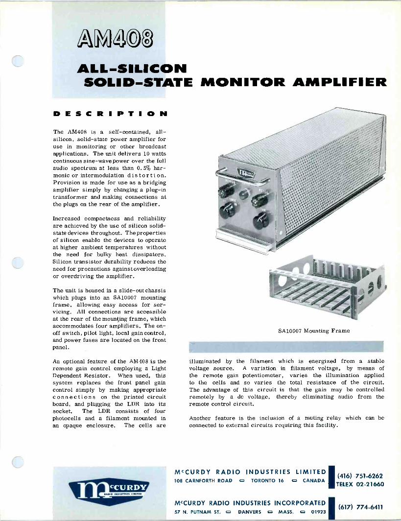
N2(JC3
ALL -SILICON SOLID-STATE MONITOR AMPLIFIER
DESCRIPTION The A141408 is a self-contained, all - silicon, solid-state power amplifier for use in monitoring or other broadcast applications. The unit delivers 10 watts continuous sine -wave power over the full audio spectrum at less than 0.5% har- monic or intermodulation distortion. Provision is made for use as a bridging amplifier simply by changing a plug-in transformer and making connections at the plugs on the rear of the amplifier.
Increased compactness and reliability are achieved by the use of silicon solid- state devices throughout. The properties of silicon enable the devices to operate at higher ambient temperatures without the need for bulky heat dissipators. Silicon transistor durability reduces the need for precautions against overloading or overdriving the amplifier.
The unit is housed in a slide -out chassis which plugs into an SA10007 mounting frame, allowing easy access for ser- vicing. All connections are accessible at the rear of the mounting frame, which accommodates four amplifiers. The on - off switch, pilot light, local gain control, and power fuses are located on the front panel.
An optional feature of the AM408 is the remote gain control employing a Light Dependent Resistor. When used, this system replaces the front panel gain control simply by making appropriate con n e c ti on s on the printed circuit board, and plugging the LDR into its socket. The LDR consists of four photocells and a filament mounted in an opaque enclosure. The cells are
SA10007 Mounting Frame
illuminated by the filament which is energized from a stable voltage source. A variation in filament voltage, by means of the remote gain potentiometer, varies the illumination applied to the cells and so varies the total resistance of the circuit. The advantage of this circuit is that the gain may be controlled remotely by a dc voltage, thereby eliminating audio from the remote control circuit.
Another feature is the inclusion of a muting relay which can be connected to external circuits requiring this facility.
MCCURDY RADIO INDUSTRIES 108 CARNFORTH ROAD o TORONTO 16 o CANADA (416) 751-6262
TELEX 02-21660
MCCURDY RADIO INDUSTRIES INCORPORATEDI (617) 774-6411
57 N. PUTNAM ST. o DANVERS o MASS. 0 01923
SPECIFICATIONS
GAIN (variable) Matched .input, 80 db f 1 db ,max
(74 db ' 1 db with terminated input)
Bridged input, 60 db f 1 db max
FREQUENCY RESPONSE (ref 1 kc)
30 cps to 20 kc within 1 db
SIGNAL-TO-NOISE 75 db below 10 watts (+40 dbm) power level with unloaded input levels of -40 dbm or -20 dbm
RELATIVE INPUT NOISE
-115 dbm (unweighted)
HARMONIC DISTORTION
Less than 0.5% from 30 cps to 20 kc at 10 watts (+40 dbm) power level
INTERMODULATION DISTORTION
Less than 0. 5% at peak level of 20 watts with the following frequencies mixed at 1:1 and 4:1 ratios:
(1) 60 cps and 2 kc (2) 60 cps and 7 kc (3) 60 cps and 12 kc
POWER OUTPUT 10 watts (+40 dbm), 30 cps to 20 kc (typical peak power 25 watts at mid -frequency)
INPUT LEVELS Matched input, -40 dbm nominal, -20 dbm max
Bridged input, -20 dbm nominal to+2 dbm max (with gain control) +2dbm nominal to+24dbm max (using gain control and input attenuator network)
INPUT IMPEDANCE Matching (transformer no. 2001); greater than 6 times source impedance (unloaded input)
Bridging (transformer no. 2002); with 600 - ohm terminated source, bridging impedance greater than 50,000 ohms (30 cps to 20 kc); with 150 -ohm terminated source, bridging impedance greater than 12,500 ohms (30 cps to 20 kc)
SOURCE IMPEDANCE
Matching, 150 or 600 ohms, balanced or unbalanced
Bridging, 150 or 600 ohms terminated with characteristic impedance, balanced or unbalanced
LOAD IMPEDANCE
4, 8, 16, 150, or 600 ohm (70v line) balanced
DAMPING FACTOR
6:1
POWER REQUIREMENTS
105 to 125 v ac/210 to 230 AT ac, 50/60 cps, 30 va with local gain control or 33 va with remote gain control
AMBIENT TEMPERATURE 55°C max
SHIPPING WEIGHT 15 lb
ORDERING INFORMATION
Monitor Amplifier AM408 with Matching Input Transformer MRI 2001
OR
Monitor Amplifier AM408 with Bridging Input Transformer MRI 2002
ACCESSORIES (not supplied)
1. SA10007 Mounting Frame 2. AM408-1 Remote Gain Control Kit 3. SA10007-1 Blank Panel
McCurdy Radio Industries reserves the right, without notice, to make such changes in equipment, design, specifications, or components as progress in engineering
or manufacturing techniques may warrant to improve the performance of the product.

SECTION: Amplifiers
Iss. 1, Mar '69
Da5©1 DMA DISTRIBUTION AMPLIFIER SYSTEMS
Choice of six systems to suit any distribution requirement.
Four or eight fully -isolated outputs, as required, from each input.
Proven AT242A amplifiers maintain program quality with wide frequency response and low distortion.
Completely prewired and pretested as a package, including 19 -inch rack frames.
DESCRIPTION The DA501 and DA502 Distribution Am- plifier Systems provide extra program quality audio outputs wherever needed, such as network, satellite studio, lobby, or any area requiring a balanced +18 dbm feed. These systems stress ver- satility, dependability, and compatibility with existing broadcast systems, plus compactness and simplicity in achieve- ment of desired functions.
The heart of both the DA501 and the DA502 is the McCurdy AT242A Universal Audio Amplifier. This is the same high- performance amplifier which has proved so successful in the program circuits of McCurdy audio mixing consoles. Each AT242A is capable of providing up to eight output splits at +18 dbm with 22 db gain in reserve. (See Block Diagram.)
The lowest input level that may be bridged is -4 dbm, with a dual 300 -ohm potentiometer adjusting the input level to the amplifier. However, if it is desired to use the distribution system in the matching mode, a level as low as -34 dbm can be accommodated. In this case, the gain control acts as the input load; the amplifier does not load the line ap- preciably, because of its high input im- pedance.
DA501 Distribution Amplifier System
The output splits are provided by SA602 Networks, each of which provides four isolated outputs. These networks mount in the acces- sory tray at the rear of the amplifier frame. In cases where one SA602 per amplifier is ordered initially, a second SA602 can be paralleled with the first to provide eight outputs from a particular amplifier.
The mounting frame is included as part of both systems, and fits a standard 19 -inch wide EIA rack.
McCURDY RADIO INDUSTRIES LIMITED (416) 751-6262 108 CARNFORTH ROAD D TORONTO 16 CANADA TELEX 02-21660
MCCURDY RADIO INDUSTRIES INCORPORATED' (716) 854-6700
1051 CLINTON STREET o BUFFALO o N.Y. 14206
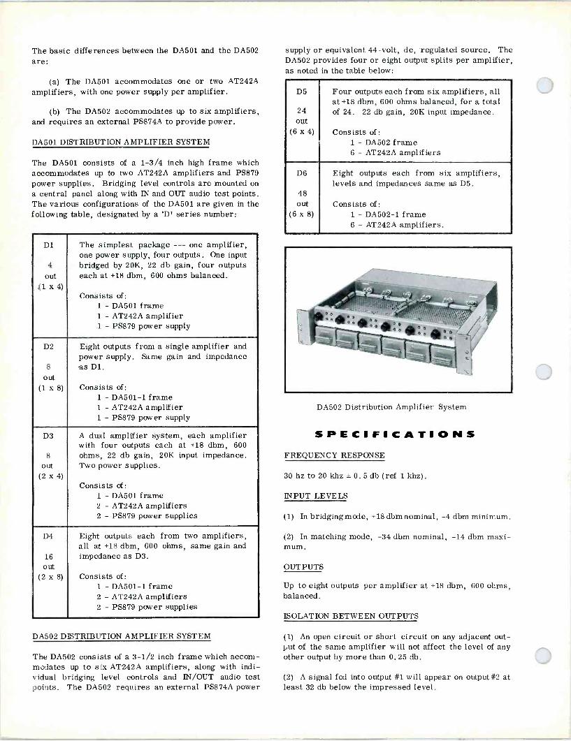
The basic differences between the DA501 and the DA502 are:
(a) The DA501 accommodates one or two AT242A amplifiers, with one power supply per amplifier.
(b) The DA502 accommodates up to six amplifiers, and requires an external PS874A to provide power.
DA501 DISTRIBUTION AMPLIFIER SYSTEM
The DA501 consists of a 1-3/4 inch high frame which accommodates up to two AT242A amplifiers and PS879 power supplies. Bridging level controls are mounted on a central panel along with IN and OUT audio test points. The various configurations of the DA501 are given in the following table, designated by a 'D' series number:
D1
4
out (1 x 4)
The simplest package --- one amplifier, one power supply, four outputs. One input bridged by 20K, 22 db gain, four outputs each at +18 dbm, 600 ohms balanced.
Consists of: 1 - DA501 frame 1 - AT242A amplifier 1 - PS879 power supply
D2
8
out (1 x 8)
Eight outputs from a single amplifier and power supply. Same gain and impedance as Dl.
Consists of: 1 - DA501-1 frame 1 - AT242A amplifier 1 - PS879 power supply
D3
8
out (2 x 4)
A dual amplifier system, each amplifier with four outputs each at +18 dbm, 600 ohms, 22 db gain, 20K input impedance. Two power supplies.
Consists of: 1 - DA501 frame 2 - AT242A amplifiers 2 - PS879 power supplies
D4
16 out
(2 x 8)
Eight outputs each from two amplifiers, all at +18 dbm, 600 ohms, same gain and impedance as D3.
Consists of: 1 - DA501-1 frame 2 - AT242A amplifiers 2 - PS879 power supplies
DA502 DISTRIBUTION AMPLIFIER SYSTEM
The DA502 consists of a 3-1/2 inch frame which accom- modates up to six AT242A amplifiers, along with indi- vidual bridging level controls and IN/OUT audio test points. The DA502 requires an external PS874A power
supply or equivalent 44 -volt, dc, regulated source. The DA502 provides four or eight output splits per amplifier, as noted in the table below:
D5
24 out
(6 x 4)
Four outputs each from six amplifiers, all at+18 dbm, 600 ohms balanced, for a total of 24. 22 db gain, 20K input impedance.
Consists of: 1 - DA502 frame 6 - AT242A amplifiers
D6
48 out
(6 x 8)
Eight outputs each from six amplifiers, levels and impedances same as D5.
Consists of: 1 - DA502-1 frame 6 - AT242A amplifiers.
DA502 Distribution Amplifier System
SPECIFICATIONS FREQUENCY RESPONSE
30 hz to 20 khz ± 0.5 db (ref 1 khz).
INPUT LEVELS
(1) In bridgingmode, +18 dbm nominal, -4 dbm minimum.
(2) In matching mode, -34 dbm nominal, -14 dbm maxi- mum.
OUTPUTS
Up to eight outputs per amplifier at +18 dbm, 600 ohms, balanced.
ISOLATION BETWEEN OUTPUTS
(1) An open circuit or short circuit on any adjacent out- put of the same amplifier will not affect the level of any other output by more than 0.25 db.
(2) A signal fed into output #1 will appear on output#2 at least 32 db below the impressed level.

INPUTS
+8VU +18 DBM 20K O
(-22)
El> BD.G
AT 242 A 1M/` O IA
M/V` O 113
1M/` 0 I 'V/V` O ID
+BVU
OUTPUTS
+I8DBM 600n
Block Diagram of Distribution Systems
SIGNAL-TO-NOISE RATIO
70 db below +18 dbm.
DISTORTION
Less than 0.5% at +18 dbm output, 30 hz to 20 khz.
CROSSTALK
Does not degrade S/N Ratio to less than 55 db, when measuring one amplifier and operating the remaining at +18 dbm output, in phase, for any frequency from 30 hz to 15 khz.
POWER REQUIREMENTS
(1) DA501: 117v ac, 60 hz, 6 va per amplifier/power supply. OPTIONAL ACCESSORIES
DIMENSIONS
(1) DA501: 1.75 in. (4.45 cm) high, 14.75 in. (37.46 cm) deep, 19 in. (48.26 cm) wide.
(2) DA502: 3.5 in. (8.9 cm) high, 14.75 in. (37.46 cm) deep, 19 in. (48.26 cm) wide.
WEIGHT (less amplifiers)
(1) DA501: 9 lb (4.1 kg).
(2) DA502: 16 lb (7.25 kg).
ORDERING INFORMATION ORDER
Specify D1, D2, D3, D4, D5 or D6 package. See Tables preceding Specifications.
(2) DA502: 44 v to 48v do at 120 ma for each amplifier, (1) PS874A Regulated Power Supply (for D5 or D6). from PS874A or equivalent. (2) SA10007 Mounting Frame for PS874A.

variable equalizer
D

ONIII3S bf HO AON311b32Id ANI, II, 3141I,'IIiiAI, GM'S AON311b32I3 1,1021d 3ON3S321d d0
NOII0I,21ISnS HO NOIIIQQI, ONIMOZZI, 30N3S32id +
3'_
M02 M01 N NZ
+
irt
NI 00S 00Z (Z)-1) A3N3003H3
SCION a AIII,O3N QNI, a AIIISOd HIOB NI 3ZavIIPM AIaIINIdNI
- A3'I 210 ADN3flb32I3 do ONIII3S ANI, II, b 1 30N3S32Id 3'IgVI2II,A
ZH0*7II,HQZd0 Sd3IS S ISOOfi dZ
001 OS OZ
SNOIIdnIIS 3'I IZn OIddIQ 2I3HI0 210d
3II,SN3dW0O 01 Q3I2IHA 3S NVD HIQIMQNI,fi
NOIIO3f321 II,HI NI S2I3I'IId I5014
ol NVHI 3ZfiIX3Zd e SHOW NOI I03f 321
ZH 09 11b11 3ZHI,I2II,A 9
b
Z
o
Z+
b+
9+
9+
01+ 99
N0Z NO S NZ NI 009 00Z
(Z).1)A3N30031,13
ilHf M02 N 01 NS NZ NI 00S 002
(ZH) AON3f1038!
49e A9NW103
001 OS
o
2
9
e
01
(90) 16008
N01
ZHN SI II, HQ Z d0 Sd3IS S ISOOfl 3H
Nî N2 NI OCZ 001 (ZH) A0N3003ä!
1
1£ óe AaM3r 03Nb HOW
OS 02 01
OZ
o
Z+
b+
9+
9+
01+ 9P
o
Y
9
e
00 09
lno
OS
Ob
02 -
CZ
01-
o 9P
02
551 03
IHOI'I ddO/11O
lno
NI
01 SI
31
6
9
2 _31 61
Jl4 d r1 D O VV
HOIIMS 120/NI
I'll" I1 111, ' II I iiihs.Ji4í1 MMIMU, !,%If1MU:M ®1en® n 1.::,C/1::: ®,ii:m®
i"e:üliïï': ® 1wni1111 t n!®I 1 M ® NO2 N01 N6 NZ NI 006 00Z
(ZH) A3N3f103213
001 OS
b+
01+ 91)
OZ
IMMIS1i:eáiU: ® üee:li::m . ,ï:e:iiie iiiiiiit?-iñ ñó%iiiíiiiíúi11:1111.1iiii:®171 1ii l\ 1á'®T1'' im:e:mli:e:mñ : iu1i:ï:'ii iiii='íiiiiïlih:iimiiie:mñe
álïiéfiii®®i1iï:miiiii:::e ®iii:: áii)i°iiilii iiï i:mñ ii:::mie M1i:e:i:i::iffliie:ii íiliii:e:mpn
N0Z NO) N4 NZ NI 004 00? (2H) AON3f103ä!
00 06 OZ
2+
b+
9+
9+
01+ 9P
rr--_ .-
1
1 ¡ 91
I
; .I
Z1
v1
e
j
1 - 9
i i 1
.
!
LiÌ z
o
( al
I . 1r7A0N:7f03adJNO`
_____
--k17
_
j. ¡
DI N£ NB NI Ot2 001 Oc 07 r1 (ZH) AON3003ö3
91
01
'II,NOI S
NIVW 01 Q,3QQI, 3g OI 30N3S321d 30 SIG 01 01 dfl
SMOZ'II, "IO2I1.N00 'MATT
ZHx S QNI, ZH OOL
N33MI3g A0N3nb32I3 ANY 30 ONIxI,dd
ONIMOZ'II, `702IINOO A0N3nb32Id 3ZfiI,I21I,A
ZH 001 II, ga 6
30 Sd3IS S NI 3'IâI,HOIIMS II10 .3'I
MI 01 II, flQ E 30 Sd3IS S
NI 3'IflVIia1IMS 1110 dH
--i--} -_
N0£ N00 NC2 N01 NS N Z 'Si l
(Z11) AON3003ö3 004 001
1fÿ
M001 N06
HOW
N Z 901 NS NZ (ZH),0N3003M3
MI 00S 00)
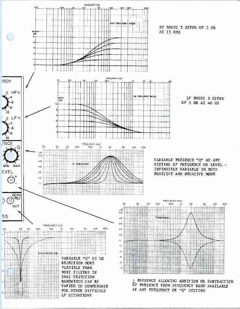
100 300 1K
FREQUENCY (Hz)
2 K 5K 10K 2 K 3 00K
' RDY
2 HF+ 4
8
10
' 2 LF+ 4
6
8
10
=NCE
MIN MAX
EVEL
60 Hz
/ DREJ
OUT
55
20
3
60 100
BO (Q
q
8
6
0
OST
dB +10
+8
+6
+4
+2
200
41GH iiREQI1ENCY 801ST
8
6
4
50 FREQUENCY (Hz)
100 200
FREQUENCY (Hz 20 50 00 200 500 IK 2K
I I I I ñ iii iil II iIlul;tr li i:iiiuu11i1iii®® 11iiiliiiii71Nñiiiiiii íiiiiî ;wiiiiMI 1iii1liiii11=CZs=;:ï::Ar',ii Ì\iiiiC: oiiCliiii 11liiii:,:::7/LiMMI::'IiE: u 'I/,/iiI `1 '\i ii1iii01/I.1.44t.: . -inom1!W^i/w:/s- i-'il1sa,:m
.I% i lii.._.-_ --- IN liiliii so mom R il ou Nunn illom
IK
FREQUENCY (Hz)
500 I K 2K 5K IOK 20K
VARIABLE "Q' 60 HZ REJECTION MORE FLEXIBLE THAN MOST FILTERS IN THAT REJECTION BANDWIDTH CAN BE VARIED TO COMPENSATE FOR OTHER DIFFICULT LF SITUATIONS
5K
dB +10
+8
+
+4
+2
-10
10K
K 3K
20K
ºob
HF BOOST 5 STEPS OF 2 DB AT 15 KHZ
10K
I
LF BOOST 5 STEPS OF 2 DB AT 40 HZ
VARIABLE PRESENCE "Q" AT ANY SETTING OF FREQUENCY OR LEVEL -
INFINITELY VARIABLE IN BOTH POSITIVE AND NEGATIVE MODE
FREQUENCY (Hz)
20 50 100 200 500 IK 2K I
5K IOK 20K
E49.: ®ii ---1--
I ilOil iil iilriliiui®ñ liiiíiiiiliiu RUBIN ii" iil1111Cliiiliiii3i 1111111111 iiIIIIIIIFAIIIIIIIINIM 1111111111 111111111 11111Cliiii=: 111011110 : ; 1N= 11I111C1:!'!111: ii i!!uIi
1111111111 1IM=sMtLer7=_11111®1811Mi5a
I \ B :qgr aliiii23 " (
!iili:!®ial®Sii!!li' 1
, iiii! 7E®iMiul®ululiui®ii \ iMEii=E=ii®IV: ®Cii='=_ENi6i®®uIIui®ii ' RYuZái:EMiieIBBIli .IIEIIi'==iQliiilIIII®IiILliiil®i ®®liiezi'iiiiRWM
==ililii 2ü ::i ; g .. g@: _ II _;: :;
+ PRESENCE ALLOWING ADDTTION OR SUBTRACTION OF PRESENCE FROM FREQUENCY BAND AVAILABLE AT ANY FREQUENCY OR "Q" SETTING

description & specifications An Equalizer designed for operational ease with many new features in one package.
Styling and size compatibe with standard fader dimen- sions.
+18 dBm output capability for maximum use of console headroom.
Unique variable "Q° presence equalization, with con- tinuously variable level, °Q°,and frequency controls.
Built-in positive/negative presence equalization. Variable "Q" 60 Hz rejection. Balanced inputs and outputs. All curves algebraically add or subtract depending on settings.
The EQ155 Variable Equalizer offers a range of equalization facilities previously requiring two or more
Gain: Unity 1 dB. Input Level: -20 dBm nom, +18 dBm max. Input Impedance: 10k ohms bridging, balanced. Provision for 600 -ohm matching input with use of internal resistor. Output Level: -20 dBm nom. +20 dBm max. Load Impedance: 600 ohms, balanced, bridging or matching. Output Impedance: Less than 50 ohms.
equalizers. Thus, with the EQ155 even the smallest installation can now employ full audio program equaliza- tion of the highest quality. The equalizing capabilities of the EQ155 are illustrated graphically in the enclosed Functional Diagram. An IN -OUT switch permits prior setup of the controls before insertion in the program circuit, or instant bypass when equalizing is not required. A pilot lamp indicates when the EQ155 is inserted. Advanced integrated -circuitry design techniques permit packaging the EQ155 in a case measuring only 1-9/16 by 5-1 /4 by 6-1 /8 inches. The shape and dimensions are compatible with modern in -line attenuator design, making the EQ155 ideal for incorporation in new consoles as well as in existing facilities. The EQ155 is installed in a panel cutout by means of two screws. Electrical connections are made via an edge -connector which facilitates removal and installa- tion of the equalizer when required.
Distortion: Less than 0.5%, 30 Hz to 20 kHz, at any output level up to +20 dBm. Noise: (all controls flat), 10 Hz to 100 kHz bandwidth .
Better than -115 dBm absolute. Power Requirement: 42v to 48v dc, 50 ma. Ambient Temperature: 0° to 55°C. Overall Dimensions: 1-9/16 in. wide, 5-1/4 in. high, 6-1 /8 in. deep. Weight: 1-1/2 lb approx. Frequency Response: Controls set for flat response (no equalization): = 0.5 dB 30 Hz to 20 kHz, ref 1 kHz.
ordering information
ORDER EQ155 Universal Equalizer which includes 15 -pin edge connector for external wiring.
Printed in Canada
McCURDY RADIO INDUSTRIES LIMITED 108 CARNFORTH ROAD, TORONTO, ONTARIO M4A 2L4 (416) 751-6262, TELEX: 06-963533
McCURDY RADIO INDUSTRIES INCORPORATED 1051 CLINTON STREET, BUFFALO, N.Y. 14206 (716) 854-6700, TWX 610-492-3219
EAST COAST OFFICE: SADDLE RIVER, N.J. P.O. BOX 86, ZIP 07458, PHONE (201) 327-0750, TWX 610-492-3219
McCurdy Radio Industries reserves the right, without notice to make such changes in equipment, design, specifications, or components as progress in engineering or manufacturing techniques may warrant to improve the performance of the product.

2C)15© 12Q9 g9
CQil 2 SOLID-STATE
Three complementary equalizer modules for professional use.
Only 1-1/2 inches wide - permits front panel mounting in line with standard straight-line attenuator.
Variable equalization in precis e steps - low frequency, high fre- quency, presence, and mid -low fre- quency compensation in one package.
No insertion loss - silicon transistor circuitry actively compensates for network losses.
IN -OUT insertion switch enables equalizer to be preset for desired effect. Self-contained relay may be operated by external do control for remote insertion.
Individual equalizing characteristics are additive or subtractive to produce a wide combination of effects.
Transient -free switching during pro- gram transmission.
150/600 -ohm source and load im- pedances, balanced or unbalanced.
Equalizer module is plug-in.
DESCRIPTION The EQ 150, EQ151, and EQ152 family of equalizers introduce a new concept in subjective equalization for professional audio use.
The EQ 150 and EQ 151 provide multi - frequency equalization with unity gain and 45 db of gain, respectively. Opera- tionally, the units are identical. Equali- zation may be varied at the important frequencies of 40 hz, 100 hz, 3 khz, 6
khz, 10 khz, and 15 khz. Low frequency
VARIABLE EQUALIZERS
50
687
L-1.37
PS]
MCCURDY RADIO INDUSTRIES LIMITED 108 CARNFORTH ROAD TORONTO 16 o CANADA
(416) 751-6262
McCURDY RADIO INDUSTRIES INCORPORATED 57 N. PUTNAM ST. c DANVERS c MASS. c 01923
(617) 774-6411

1
w
C
2
BOOST (Ds)
¡
FREQUENCY (H2)
D
loo
1111111101111111111.3111111 111111N111111 '- 1 11Y1MI1111111111 1ìi!!IIIIII11 1111ìi 1IIIII111 111111 ie2111111I1 111111iiï::!1
11111111 1 II 11 111 m11 YYIler
7 20
)
FNEOUENCY(N2)
50 100 230
12
I
IK 2K 3K
71
LIEAIpOLE(. 1-_ EQwLl2IK(( GKMGCTFRIfTl,3
JT' _OW FRFOU NrY c
FREQUENCY (NO QG Z
11111111«11111111111111111111111111 OVALIZINQ N AC CR S CB
111111111111111111111 III 11111111OihN11111I111111 1111111111»iiìM111111111 1111111111ì::3:;111111 1111111i1I11111111iiiiì:e11111I 111111ÌÌM1111111 Ñ1 11
iAIïIliiHH I
11111 111LI11I11111 11
I I,
IOK
w o
60GST. Old
2
2
D
SOO FREQUENCY (NV
2K 3K 7K 2 K 3pK
I
EQI B E0131 Nu. liVlE SNSYCTNIUÌT(45. I-+.
MESE{1CN MN. i j
Ili
IOK
100
Bobar
L
aRCSENCE BOOS' SKNtj
1
I
I I
BO ID
e
6
2
O
570 FREQUENCY (N2)
(K _-YIC 5K 10K 27K 30K
um jr.><T
POSI Fowl
E0150 17.1115
INN PINO RItY B
73T -j
100
{
lo
Ip CU (DIo 0
5
Kl
15
2C
25
X
35
40
- {
00 FKEQIIENCY(Nd
N 2K 5K KM 2 K 50K
EA
00K
T
' I EAISO E3d1 EQWLINS TpRIST16$
HONFBEQUENCY U}
FREQUENCY (0.1 20 50 100 200 1K 2K
TOOK
1C
loo
(D
0
5
tso S00 ' - K j
2C0
Lti
20
25
3C
as
ea
500 1
2a
FREQUENCY INK) 2K 5K IOK 20K SOK
1
BOOK
lK HI a 6K - I1 101112K
E0152 I
OURLIZING, CHARACTERISTICS I
-1RGRìN[QuCmrC LOIUT(FPSSI 1 1 1 I 1. 1

boost occurs at 40 hz and low frequency cut at 100 hz. The high frequency boost occurs at 15 khz and the high frequency cut at 10 khz. A selectable presence control establishes a resonant peak to emphasize the program transmission at 3 khz or 6 khz. Alternatively, the presence effect can be substituted with a low frequency platform boost below 100 hz. The amplitude of the selected frequencies is adjustable in 2 db increments for boost and 3 db increments for cut.
The EQ 152 incorporates active, variable, high-pass and low-pass filters in one compact unit. A mode switch permits the high- and low-pass filters to work at two sensitivity ranges individually or in tandem. The equali- zer has unity gain. Ten cutoff frequency positions are available in each LF and HF mode; the cutoff rate is 18 db per octave. The LF control selects cutoff at 70 hz, 100 hz, 150 hz, 250 hz, 500 hz, 1 khz, 2 khz, 3 khz, 5 khz, and 7.5 khz. The HF control selects cutoff at 500 hz, 1 khz, 2 khz, 3 khz, 4 khz, 5 khz, 6 khz, 8 khz, 10 khz, and 12 khz.
The EQ 150, EQ 151, and EQ 152 are compact plug-in modules designed for front panel mounting with con- ventional straight-line mixing attenuators. The equalizer modules fully meet the need for comprehensive, variable equalization through the audio spectrum in sound mixing and broadcast facilities. Each module contains the
amplifiers and transformers necessary to operate balanced or unbalanced and with gain or at unity gain.
Each equalizing characteristic is achieved by using an individual active circuit which permits additive or sub- tractive equalization, resulting in a wide range of com- pounded characteristics.
Advanced solid-state circuitry using silicon transistors and field-effect devices enable the units to perform with optimum signal-to-noise and inherent low distortion within a system.
Premium quality gold switches permit transient -free equalizing adjustments to be made during program transmission. An IN -OUT insertion switch provides instant operation from a preset condition. The EQ150 and EQ152 incorporate hermetically -sealed relays for remotely controlled insertion of a preset effect.
Blank Module
The EQ150-2 Blank Module is used when it is necessary to remove an equalizer, yet maintain the signal path. This is extremely useful when it is desired to preset an equalizer in different mixer channels. To accomplish this, it is necessary only to transfer the equalizer from one EQ 150-1 mounting frame to the other, and insert the EQ 150-2 into the empty mounting frame.
SPECIFICATIONS Item EQ 150 EQ 151 EQ 152
Equalizing Characteristics:
(1) Low Frequency 2 db per step in 5 steps at 2 db per step in 5 steps at Boost 40 hz. 40 hz.
(2) Low Frequency 3 db per step in 5 steps at 3 db per step in 5 steps at Low Frequency Cut (High Pass) in Cut 100 hz. 100 hz. hz, at -3 db points; Off, 70, 100, 150,
250, 500, 1000, 2000, 3000, 5000, and 7500.
(3) Mid -Low Fre- 2 db per step in 4 steps; 2 db per step in 4 steps; quehcy Boost platform below 100 hz. platform below 100 hz.
(4) Presence Boost 2 db per step in 4 steps; resonant peak selectable at 3 or 6 khz.
2 db per step in 4 steps; resonant peak selectable at 3 or 6 khz.
(5) High Frequency 2 db per step in 5 steps at 2 db per step in 5 steps at Boost 15 khz. 15 khz.
(6) High Frequency 3 db per step in 5 steps at 3 db per step in 5 steps at High Frequency Cut (Low Pass) in Cut 10 khz. 10 khz. hz, at -3 db points; 500, 1000, 2000,
3000, 4000, 5000, 6000, 8000, 10000, 12000, Off.
(7) Rate of 6 db per octave. 6 db per octave. 18 db per octave. Attenuation
Tolerance for above figures Boost and Cut within ± 0.5 db per step; Frequencies within ± 10%.
(CONT'D OVERLEAF)

Item EQ 150 EQ151 EQ152
General Characteristics:
(1) Gain (t 1 db) Set to unity. Set to 45 db. Set to unity.
(2) Frequency W ithin t 0.5 db, 50 hz to W ithin f 0.5 db, 50 hz to W ithin t 0.5 db, 50 hz to 20 khz Response (effects controls at Z ero or Off)
20 khz (ref 1 khz). 20 khz (ref 1 khz). (ref 1 khz).
(3) Signal -to -Noise 90 db below 0 dbm output 75 db below 0 dbm output (a) 75 db below 0 dbm output level, Ratio level, level. with mode switch in (+) or high
sensitivity position.
(b) 85 db below +20 dbm output level, with mode switch in (-) or low sensitivity position.
(4) Harmonic Less than 0.5% at +10 dbm Less than 0.5% at +10 dbm Less than 0.5% at +20 dbm output, Distortion output, 30 hz to 20 khz, output, 20 hz to 20 khz. 30 hz to 20 khz.
(5) Input Levels -10 dbm nom, +10 dbm -35 dbm nom, -25 dbm (a)Mode switch in (+) or high max. max. sensitivity position; -10 dbm nom,
0 dbm max.
(b) Mode switch in ( -) or low sensitivity position; 0 dbm nom, +20 dbm max.
(6) Output Levels -10 dbm nom, +10 dbm max.
+10 dbm nom, +20 dbm max.
-10 dbm nom, +20 dbm max.
(7) Source 150 or 600 ohms, balanced 150 or 600 ohms, balanced 150 or 600 ohms, balanced or Impedance or unbalanced. or unbalanced, unbalanced.
(8) Input Impedance 150 or 600 ohms *10%, balanced.
150 or 600 ohms * 10%, balanced.
150 or 600 ohms *10%, balanced.
(9) Load Impedance 150 or 600 ohms, balanced 150 or 600 ohms, balanced 150 or 600 ohms, balanced or or unbalanced. or unbalanced. unbalanced.
(10) Output 1/3 load impedance. 1/3 load impedance. 1/3 load impedance. Impedance
(11) Remote Insertion Self-contained relays. Self-contained relays.
(12) Power 36v dc at 70 ma, from 36v do at 70 ma, from 36v do at 135 ma, from PS874 or Requirements PS874 or equivalent. PS874 or equivalent. equivalent.
(13) Ambient 0°C to 55°C. 0°C to 55°C. 0°C to 55°C. Temperature
(14) Overall 1-1/2 in. wide, 7-1/2 in. 1-1/2 in. wide, 7-1/2 in. 1-1/2 in. wide, 7-1/2 in. deep, Dimensions deep, 7-1/2 in. long, deep, 7-1/2 in. long. 7-1/2 in. long.
(15) Finish Nickel -cadmium case with Nickel -cadmium case with Nickel -cadmium case with black
(16) \Weight
black anodized front panel.
3-1/4 lb.
black anodized front panel,
3-1/4 lb.
anodized front panel.
4-1/4 lb.
ORDERING INFORMATION ORDER: EQ150, EQ151, or EQ152 Equalizer. OPTIONAL ACCESSORIES: (1) EQ150-1 Mounting Frame; (2) EQ150-2 Blank Module.
McCurdy Radio Industries reserves the right, without notice, to make such changes in equipment, design, specifications, or components as progress in engineering or manufacturing techniques may warrant to improve the performance of the product.
zz\2-ezz% digital counter
I : ;235 6
i
The SA 137A Dicital Coo -0.er aczepts Lp to four displays
125'S b

SA 137A DIGITAL COUNTER
specifications
1. Compact master unit, only 31/2" in height, mounts in standard 19" equipment rack.
a) Maximum power requirement at 117V, 60 Hz is lA.
b) All cable connections are to the rear of the unit.
c) 60 Hz power line frequency is used as the counter time base.
2. The SA137A Digital Timer accepts a maximum of 4 display units.
a) Each remote may be a maximum of 100' from the master (Cable length).
b) The remotes are connected to the master with 25 conductor ribbon cable. Conventional cable may also be used. (option)
c) The remote may be mounted in the console VU housing, or any other panel. It occupies 215/16"x 5" of panel space and 17/16" behind the panel. It mounts in a standard VU meter cutout.
d) Each readout is equipped with five digits, tens and units of minutes and seconds and tenths of seconds. For ease of reading, the tenths of seconds only displays even tenths, 2, 4, 6, 8, 0. The maximum elapsed time displayed is 99 minutes 59.8 seconds.
e) The minutes and seconds displays are 0.510" high, red LED types and the tenth seconds display is a 0.300" high, red LED type. A colon is provided between the minutes and seconds digits and a decimal point between the seconds and tenths of seconds.
3. Two standard control panels are available. One mounts in four unit widths of the console remote control tray (315/16x45/8). The other mounts in a standard 71/2", double width (31/8"), attenuator module. Both are designed to be compatible with modular consoles, mounting directly on the console control panel.
Printed in Canada SA 137A Digital Timer/Issue 3/12.76
The controls provided and their functions are as follows:
a) Four thumbwheel switches for setting tens and units of seconds and minutes.
b) Start switch -starts counter.
c) Stop switch -stops counter, display remains at stop time.
d) Hold switch -holds display, counter continues to run. When switch is released the display updates to counter.
e) Clear switch -clears display and resets counter to zero.
f) Load switch -enters time set on thumbwheel switches into counter.
g) Up/Down switch -sets counter operating mode, either counting up or down from a preset time.
4. Remote control connections are available on the master unit for starting and resetting the counter when other equipment, such as tape machines, are started or stopped. This can be used for automatic timing of running time.
5. In the down -count mode, a ground going signal is available momentarily upon reaching zero. The counter remains at zero, flashing the display to indicate duration count is ended.
Ordering information/model types a)Master unit -SA 137A
b)Remote display, VU Meter Mounts -SA 137A-01
c) Remote display, cue speaker mount -SA 137A-02
d) Control panel: Attenuator module mounting: SA 137A-06 Remote control tray mounting: SA 137A-07
e) Interconnecting cables - SA 137A -C -(Last two digits give cable length in feet, i.e. SA 137A-000 is a 100 ft. cable and SA 137A-007 is a 7 ft. cable.)
McCurdy Radio Industries reserves the right without notice to make auch changes in equipment, design, specifications, or components, as progress in engineering or manufacturing techniques may warrant, to improve the performance of the product.
McCurdy Radio Industries Limited, 108 Carnforth Road,Toronto, Ontario M4A 2L4 (416) 751-6262 Telex: 06-963533
McCurdy Radio Industries Incorporated, TWX: 610-492-3219 1051 Clinton Street, Buffalo, N.Y. 14206 (716) 854-6700 Telex: 06-963533
U.S.A. East Coast Office, Saddle River, N.J. P.O. Box 86, 07458 (201) 327-0750

reel tape switcher
o
description & specifications SA 141 REEL TAPE SWITCHER
Compact and self contained. Accepts -20 dBm to +8 dBm 10 K Bridging. 3 -Watt monitoring with pre -post mode. Standard EIA Rack Panel 31/2 in. x 19 in. Amphenol blue ribbon connectors for inputs and outputs. A. 20 Source input selector (10 K Bridge) B. Telco feed select C. Switcher input select D. Program gain control E. Two way output select F. Monitor gain control G. Monitor head -set jack H. Monitor speaker
All inputs and outputs are wired to Amphenol blue ribbon connectors at the rear of the unit.
MAX. GAIN ±1 dB. Pgm: 28 dB max. Mon: 55 dB max.
FREQUENCY RESPONSE (Ref. 1 kHz) Pgm: ±0.5 dB, 20 Hz to 20 kHz. Monitor: ±0.5 dB, 20 Hz to 20 kHz.
NOISE Pgm: -85 dB below +18 dBm. Monitor -75 dB below 3 -Watts.
HARMONIC DISTORTION Pgm. 0.5%, 20 Hz to 20 kHz at + 14 dBm. Monitor: 0.5%, 20 Hz to 20 kHz at 3-W, 8 ohms.
INPUT LEVELS (Nominal) -20 dBm, Bal/Unbal.
OUTPUT LEVELS (Nominal) +4 dBm/+8 dBm, 600 ohms Bal.
SOURCE IMPEDANCE 600 ohms.
INPUT IMPEDANCE 10 K ohms.
POWER REQUIREMENTS 115 V//60 Hz single phase.
OVERALL DIMENSIONS 19 in. Wide, 31/2 in. High, 7 in. Deep.
WEIGHT 7 lb. approx. (3.18 kg).
INPUT I
INPUT 20 «4(
CART.
TAPE
INPUT SELECT
INPUT SELECT
CART
o o
TAPE
108/10K PGM GAIN
MONITOR GAIN
o
o
LINE I
LINE 2
HEADSET
> IOdBm, 60011
>>1+8dBm,600[1
POWER SUPPLY
b
^ 115V AC
60Hz
3W, 8R
i TO TELCO
Printed in Canada
McCURDY RADIO INDUSTRIES LIMITED 108 CARNFORTH ROAD, TORONTO, ONTARIO M4A 2L4 (416) 751-6262, TELEX: 06-963533
McCURDY RADIO INDUSTRIES INCORPORATED 1051 CLINTON STREET, BUFFALO, N.Y. 14206 (716) 854-6700, TWX 610-492-3219
EAST COAST OFFICE: SADDLE RIVER, N.J. P.O. BOX 86, ZIP 07458, PHONE (201) 327-0750, TWX 610-492-3219
McCurdy Radio Industries reserves the right, without notice to make such changes in equipment, design, specifications, or components as progress in engineering or manufacturing techniques may warrant to improve the performance of the product.
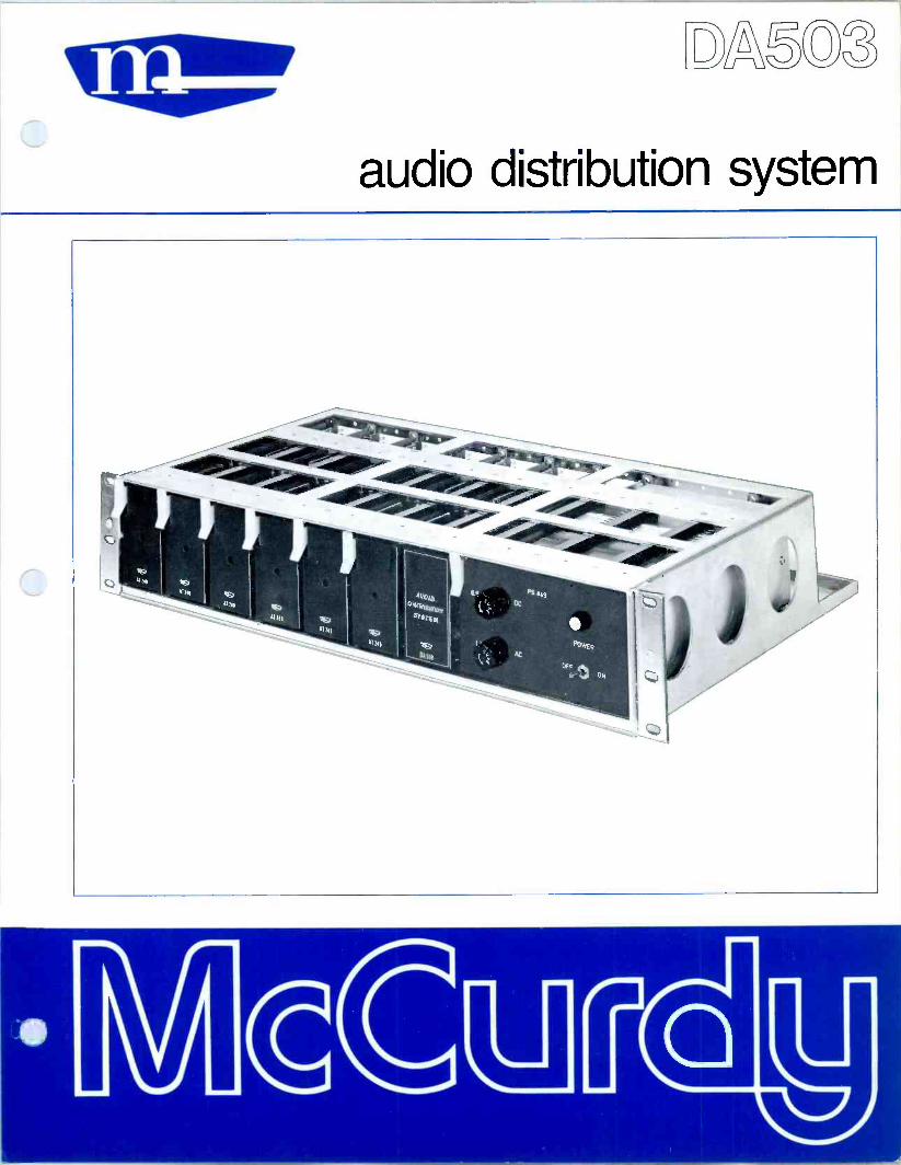
A5 3
audio distribution system

description & specifications The DA503 Audio Distribution System is designed for audio distribution in broadcasting or other commercial applications where professional quality must be main- tained. The DA503 consists of an FR904 19 -inch Equipment Frame which holds up to six AT249 Distribution Amplifiers and one PS849 Power Supply. Each AT249 bridges one input at any specified level from -30 dBm to 0 dBm, and provides six isolated outputs at +8 dBm 600 ohms. Thus, a complete
Frequency Response: 20 Hz to 20 kHz, 1 dB (ref 1
kHz). Input Levels: -30 or 0 dBm depending on strapping on PC Board and Gain adjustment. Max Gain: 48 dB, ± 1 dB. (Gain variable 0 to 48 dB with front panel gain control.) Outputs: Up to six outputs per amplifier at +8 dBm (+18 dBm). Source Impedance: 600 ohms terminated. Input Impedance: Greater than 10,000 ohms.
complement of six amplifiers can provide 36 outputs from six inputs. The wide input dynamic range is made possible by pad selection and preset gain adjustment. A distortion figure of less than 0.5°ro is maintained over the specified input levels and the frequency band of 30 Hz to 20 kHz. The FR904 Equipment Frame mounts in a standard 19 -inch rack or pedestal and occupies only 3-1 /2 inches of vertical space.
Load Impedance: 600 ohms or higher; balanced. Noise: 75 dB to 85 dB below +18 dBm, depending on gain control setting. Distortion: Less than 0.5°c with -20 dBm input and +18 dBm output, 30 Hz to 20 kHz. Power Requirement: 115v ac, 60 Hz, 40 VA for full complement of six amplifiers. Dimensions: 3-1/2 in. high, 13-3/8 in. deep, 19 in. wide. Weight: 22 lb approx.
rAT 249 DISTRIBUTION AMPLIFIER (UP TO 6)
-30 dBm OR O dBm_< 60011
115 V
60 Hz f--
PS849 POWER
SUPPLY
GAIN (ON FRONT PANEL)
- - } 6 SPLITS t 8 dBm
60011 I+18dBml
ordering information Order DA503 Distribution Amplifier Assembly and specify quantity of AT249 Amplifiers up to a maximum of SIX.
The standard DA503 includes the PS849 Power Supply and the FR904 Equipment Frame, prewired for the customer to connect inputs and outputs.
Printed in Canada
McCURDY RADIO INDUSTRIES LIMITED 108 CARNFORTH ROAD, TORONTO, ONTARIO M4A 2L4 (416) 751-6262, TELEX: 06-963533
McCURDY RADIO INDUSTRIES INCORPORATED 1051 CLINTON STREET, BUFFALO, N.Y. 14206 (716) 854-6700, TWX 610-492-3219
EAST COAST OFFICE: SADDLE RIVER, N.J. P.O. BOX 86, ZIP 07458, PHONE (201) 327-0750, TWX 610-492-3219
McCurdy Radio Industries reserves the right, without notice to make such changes in equipment, design, specifications, or components as progress in engineering or manufacturing techniques may warrant to improve the performance of the product.

gM2 5N12
DESCRIPTION The SM8 and SM18 Switching Modules are the basic building-blocks for sophis- ticated, low -transient, audio switching systems. A full -complement module accommodates eight relays, a silicon - transistor hold -cancel circuit, and re- sistive isolation pads. The SM8 uses high -reliability reed relays while the SM18 uses armature relays; otherwise, the two modules are identical. The use of silicon diodes in the switching circuits virtually eliminates transients and pre- vents back -coupling.
The circuitry is ruggedly constructed on a glass -epoxy printed -circuit card which attaches to an aluminum extrusion. A metal backing -plate is used to further increase the rigidity of the module.
AUDIO SWITCHERS
AUDIO SWITCHER FRAME SHOWING SM 8 REED RELAY MODULE
The full SM8 or SM18 module is an 8x 1 switcher and/or mixer, pro- viding one output from any one or all eight inputs, depending on the wiring configuration of the hold -cancel circuit. However, less than the full complement of circuits may be ordered on any module in order to suit the needs of individual system requirements. Con- versely, modules may be stacked or paralleled to increase the input -to -output ratio from the basic 8 x 1 system.
A wide variety of control configurations and switch types may be used with these switchers, including momentary or alternate action pushbuttons, or lever keys. A few examples are given in the follow- ing paragraphs and accompanying diagrams (see over) .
MCCURDY RADIO INDUSTRIES LIMITED 108 CARNFORTH ROAD 0 TORONTO 16 D CANADA
MCCURDY RADIO INDUSTRIES INCORPORATED 1051 CLINTON STREET o BUFFALO o N.Y. 14206
I(416) 751-6262 TELEX 02-21660
(716) 854-6700
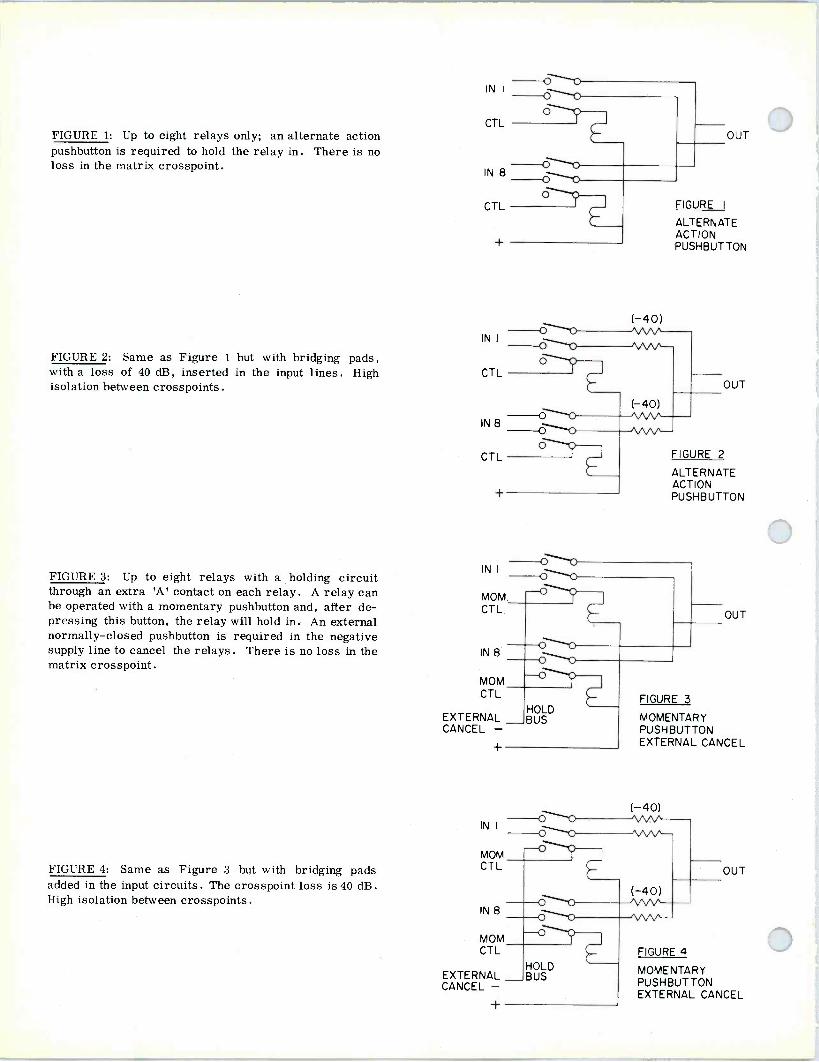
FIGURE 1: Up to eight relays only; an alternate action pushbutton is required to hold the relay in. There is no loss in the matrix crosspoint.
FIGURE 2: Same as Figure 1 but with bridging pads, with a loss of 40 dB, inserted in the input lines. High isolation between crosspoints.
FIGURE 3: Up to eight relays with a holding circuit through an extra 'A' contact on each relay. A relay can be operated with a momentary pushbutton and, after de- pressing this button, the relay will hold in. An external normally -closed pushbutton is required in the negative supply line to cancel the relays. There is no loss in the matrix crosspoint.
FIGURE 4: Same as Figure 3 but with bridging pads added in the input circuits. The crosspoint loss is 40 dB. High isolation between crosspoints.
IN I
CTL
CTL
(-40)
OUT
FIGURE I
ALTERNATE ACTION PUSHBUTTON
OUT
FIGURE 2
ALTERNATE ACTION PUSHBUTTON
Oti IN I o -o MOM. CTL. OUT
OHO IN 8 OHO MOM_ CTL FIGURE 3
HOLD EXTERNAL BUS MOMENTARY CANCEL - PUSHBUTTON
EXTERNAL CANCEL
( OO VvV` IN I "Vv MOM
0
CT L OUT
(-40) IN 8
OHO \ M/w -
MOM CTL FIGURE 4
EXTERNAL CANCEL -
MOMENTARY PUSHBUTTON
HOLD BUS
EXTERNAL CANCEL +

FIGURE 5: Up to eight relays with a holding circuit through an extra 'A' contact on each relay, and a tran- sistorized hold -cancel circuit. Relays are operated by momentary pushbuttons. The holding circuit is a tran- sistorized switch that changes its state when a negative potential is applied to the external cancel connection; or, by inserting diodes in the proper locations, the relay(s) are cancelled by the next selection.
FIGURE 6: Same as Figure 5 but with bridging pads inserted in the inputs. Insertion loss is 40 dB. High isolation between crosspoints.
IN I
MOM CTL
IN 8
MOM CTL
SUPPLY
EXTERNAL CANCEL -
INTERNAL CANCEL CIRCUIT
OUT
FIGURE 5
MOMENTARY PUSHBUTTON AUTO INTERNAL/ EXTERNAL CANCEL
(-40) OO MW IN I ^M/\ OO -- MOM CTL OUT
(-40) IN 8
OO NNA.A
MOM FIGURE 6 CT L
MOMENTARY PUSHBUTTON AUTO INTERNAL/
INTERNAL EXTERNAL CANCEL CANCEL
SUPPLY CIRCUIT + EXTERNAL CANCEL -
SM8 Reed Relay Switching Module SM18 Armature Relay Switching Module

SPECIFICATIONS SYSTEM QUANTITIES
Eight relays per module. Twenty modules per frame.
CARD DIMENSIONS
53/64 in. wide, 3 in. high, 10-13/16 in. long. Frame occupies 3-1/2 in. of vertical space in a 19 in. rack.
ORDER
OPERATING VOLTAGE
24v do unregulated.
CURRENT
(A) 10 mA per reed relay (SM8) .
(B) 40 mA per armature relay (SM18) .
ORDERING INFORMATION
(A) Reed relay. (B) Armature relay. (C) SM8/SM18 Modules. (D) Isolation pads. (E) Transistor hold -cancel circuit.
OPTIONS
(A) FR904 Equipment Frame. (B) FR904-2 Frame Receptacle Kit. (C) Power Supply, 24v dc .
(D) Power Supply Mounting Frame.
3
McCurdy Radio Industries reserves the right, without notice, to make such changes in equipment, design, specifications, or components as progress in engineering
or manufacturing techniques may warrant to improve the performance of the product.

speaker -amplifier assemblies

description & specifications The LSA609 Speaker/Amplifier Assembly is designed to provide quality sound from monitor feeds or from audo distribution systems. The 10 -watt amplifier used in this assembly supplies an adequate reserve of low - distortion power which, combined with the acoustically -designed speaker enclosure, makes this assembly ideal for Studio, Control Room, or Classroom monitoring.
The LSA609 has a 15 -degree reverse slope for wall -mounting and is fitted with a hanger bracket. It has a high -impedance input necessary for bridging a 600 -ohm line, and uses the McCurdy AM415 10 -watt Power Amplifier to drive a dual -cone speaker.
Input Level: 0 dBm, bridging, unbalanced. Output Level: 10 watts max, 8 ohms. Source Impedance: 600 ohms, unbalanced, or trans- former balanced. Input Impedance: 10,000 ohms, unbalanced.
The dual -cone speaker is used with a special surround damping treatment to lower the free -air resonance and provide optimum damping at low frequencies. This results in an assembly possessing extremely low distortion and wide frequency response characteristics. Additional damping is applied to the interior of the speaker compartment to reduce spurious reflections from the inner surface. The cabinet material is hand -rubbed walnut, with a frontal finish of open -weave material chosen to reduce high -frequency attenuation. Input connections are easily made to screw terminals at the rear of the amplifier. A volume control and ac fuse are recessed in the side of the cabinet.
System Frequency Response: ± 3 dB, 50 HZ to 18 kHz. Power Requirements: 117v ac, 60 Hz, 30 va. Dimensions: LSA609: 11-11/16 in. deep at top, 8 in. deep at bottom, 13-3/8 in. high, 21-19/32 in wide. Weight: Approximately 32 lb.
ordering information ORDER LSA609 Speaker/Amplifier Assembly for wall mounting.
178 Printed In Canada
McCURDY RADIO INDUSTRIES LIMITED 108 CARNFORTH ROAD. TORONTO. ONTARIO M4A 2L4 (416) 751-6262, TELEX 06-963533, TWX 610-492-1373
McCURDY RADIO INDUSTRIES INC. UNITED STATES HEAD OFFICE
1711 CARMEN DRIVE, ELK GROVE VILLAGE, ILLINOIS 60007, (312) 640-7077, TWX 910-222-0436 EAST COAST OFFICE
223 WEST SADDLE RIVER ROAD, SADDLE RIVER, N.J. 07458, (201) 327-0750, TWX 710-988-2254
BUFFALO WAREHOUSE
1051 CLINTON STREET, BUFFALO, N.Y 14206, DIRECT LINE TO TORONTO PLANT (716) 854-6700, TWX 610-492-1373
McCurdy Radio Industries reserves the right, without notice to make such changes in equipment, design, specifications, or components as progress in engineering or manufacturing techniques may warrant to improve the performance of the product.

ge3 giC)))
DESCRIPTION The LSA608 and LSA609 Speaker/Ampli- fier Assemblies are designed to provide high -quality sound from monitor feeds or from audio distribution systems. The 10 -watt amplifier used in these assem- blies supplies an adequate reserve of low -distortion power which, combined with the acoustically -designed speaker enclosure, makes either assembly ideal for Studio, Control Room, or Classroom monitoring.
The LSA608 has a rectangular shape de- signed for table -top mounting. The LSA609 has a 15 -degree reverse slope for wall -mounting and is fitted with a hanger bracket. Electronically, the units are identical, both having the high - impedance input necessary for bridging a 600 -ohm line, and using the McCurdy AM415 10 -watt Power Amplifier to drive a modified Philips 9710M dual -cone speaker.
The dual -cone speaker is used with a special surround damping treatment to lower the free -air resonance and provide
SPEAKER- AMPLIFIER ASSEMBLIES
TWO SELF-CONTAINED SPEAKER -
AMPLIFIER UNITS OFFERING QUALITY
PERFORMANCE FOR AUDIO
MONITORING
LSA608
optimum damping at low frequencies. This results in an assembly possessing extremely low distortion and wide frequency response characteristics. Additional damping is applied to the interior of the speaker compartment to reduce spurious reflections from the inner surface.
The cabinet material is hand -rubbed walnut, with a frontal finish of open -weave material chosen to reduce high -frequency attenuation.
Input connections are easily made to screw terminals at the rear of the amplifier . A volume control and ac fuse are recessed in the side of the cabinet.
McCURDY RADIO INDUSTRIES LIMITED (416) 751-6262 10P CARNFORTH ROAD o TORONTO 16 o CANADA TELEX 02-21660
MCCURDY RADIO INDUSTRIES INCORPORATED 1051 CLINTON STREET o BUFFALO o N.Y. 14206
(716) 854-6700

SPECIFICATIONS INPUT LEVEL POWER REQUIREMENTS
0 dBm, bridging. 117v ac, 60 Hz, 30 va.
OUTPUT LEVEL 10 watts max, 8 ohms. DIMENSIONS
SOURCE IMPEDANCE (A) LSA608: 9-5/16 in. deep, 13-7/16 in. high, 21- 600 ohms, balanced or unbalanced. 19/32 in. wide.
INPUT IMPEDANCE Greater than 10 times source impedance.
(B) LSA609: 11-11/16 in. deep at top, 8 in. deep at bottom, 13-3/8 in. high, 21-19/32 in wide.
SYSTEM FREQUENCY RESPONSE WEIGHT f 3 dB, 50 Hz to 18 kHz. Approximately 32 lb.
ORDERING INFORMATION ORDER LSA608 Speaker/Amplifier Assembly for table mounting. LSA609 Speaker/Amplifier Assembly for wall mounting.
McCurdy Radio Industries reserves the right, without notice, to make such changes in equipment, design, specifications, or components as progress in engineering
or manufacturing techniques may warrant to improve the performance of the product.

SECT ION: Turntables
Iss. 1; Feb '68
gg315U MONAURAL DISC REPRODUCER
DESCRIPTION The SS3152A Monaural Disc Reproducer provides complete facilities for pro- fessional reproduction of monaural disc recordings. The SS3152A is completely self-contained with three -speed turn- table, viscous -damped tone arm, plug-in pickup cartridge, equalized preampli- fier, audio cue switching, and power supply.
A block diagram of the SS3152A is shown in Figure 2. The standard tone arm is a Gray 208-S fitted with a variable reluc- tance, stereo, professional -type, pickup cartridge. The cartridge output is equal- ized and amplified by an AT131 pream- plifier which incorporates an input im- pedance selector for various types of cartridge, a gain control, and a roll -off selector. The roll -off selector is located on the cue panel (see Fig. 1) and selects either RIA A equalization or extra roll -off at 10 khz for exceptionally noisy records.
The audio output is delayed slightly on turntable start to prevent starting 'wow'. The turntable may be started locally by means of the turntable speed control, or remotely by means of an external push- button or lever key. A motor start and cue pushbutton, located on the cue panel, permit turntable control independent of the remote switch, and audio cue switch- ing to an external bus with bypass of the audio delay circuit.
The cabinet of the SS3152A presents a new approach to modular enclosures by McCurdy, ensuring harmony with other equipment and enabling buildup of the control room "package" (see Fig. 3).
Figure 1. SS 3152A Disc Reproducer, with Optional End Bells Mounted
The top is of laminated formica, ivory in color, and the cabinet is finished in textured blue. An arm guard at the rear helps prevent accidental displacement of the tone arm. All audio, power, and con- trol connections are accessible at the rear of the unit, and are made via connectors which are provided as standard equipment (audio con- nectors are Cannon XLR types).
McCURDY RADIO INDUSTRIES LIMITED (416108
CARNFORTH ROAD o TORONTO 16 o CANADA Telex 751-6262 02-21660
MCCURDY RADIO INDUSTRIES INCORPORATED 57 N. PUTNAM ST. o DANVERS o MASS. c 01923
(617) 774-6411

CARTRIDG
RIAA/ROLLOFF
EQ SW
MOTOR 0 -
ATI31 -14
EQUALIZED PREAMPLIFIER
24V O O C_-_+
K2
(-12)
(-6)
COMM CUE PB
XLR 3-13 PGM
OUTPUT -20 VU 60011
XLR 3-14 CUE
OUTPUT -26 VU 60011
o-I KI COMM OTOAT131
POWER SUPPLY
T -,D 0 24V OCOMMON 24V 0
0 - MOTOR CUE
C 117/230VAC
XLR4-13
BF« L
REMOTE START CONTROL
START I
(NOT SUPPLIED)
Figure 2. Block Diagram of SS3152A.
SPEC DRIVE ASSEMBLY
(1) Speed Ranges: 33-1/3, 45, and 78 rpm.
(2) Speed Regulation: ±0.2% on all ranges.
I F I C A T I O N S ELECTRONIC ASSEMBLY (cont)
(6) Output Impedance: 600 ohms, balanced.
(3) Noise and Rumble: Better than -35 db ref 1.4 cm/sec peak velocity at 100 hz.
(4) Flutter and Wow: Less than 0.17%.
(5) Power Requirement: 117v ac, 60 hz, single phase, 46va (50 hz drives can be supplied).
ELECTRONIC ASSEMBLY
(1) Input Level: 5 mv.
(2) Input Impedance: Variable from 10k to 75k ohms.
(3) Equalization: RIAA or extra high -frequency roll -off (see Fig. 4)
(4) Frequency Response:
(a) Without roll -off filter; ±ldb of RIAA curve, 30 hz to 15 khz, ref 1 khz.
(b) Roll -off; Greater than 14 db below RIAA re- sponse at 10 khz.
(5) Output Levels:
(a) Program; -20 dbm nom, 0 dbm max.
(b) Cue; -26 dbm nom, -6 dbm max.
(7) Distortion: Less than 0.5% at 0 dbm output, 30 hz to 15 khz, using reverse RIAA input network.
(8) Output Noise Level: -64 dbm with 510 -ohm input termination.
(9) Power Requirement: 117v ac, 50/60 hz, single phase, 27va (may be strapped for 230v operation).
TONE ARM AND CARTRIDGE
(1) Arm: Gray 208-S.
(2)
(3)
Cartridge: Shure M44C Stereo with 0.7 mil stylus.
Tracking Weight: Adjustable.
MECHANICAL
(1) Dimensions: 33-1/4 in. high (29 in. to top of For- mica), 22 in. wide, 22-1/2 in. deep. Each end bell (optional) adds 3/4 in. to width.
(2) Finish: Baked textured acrylic blue.
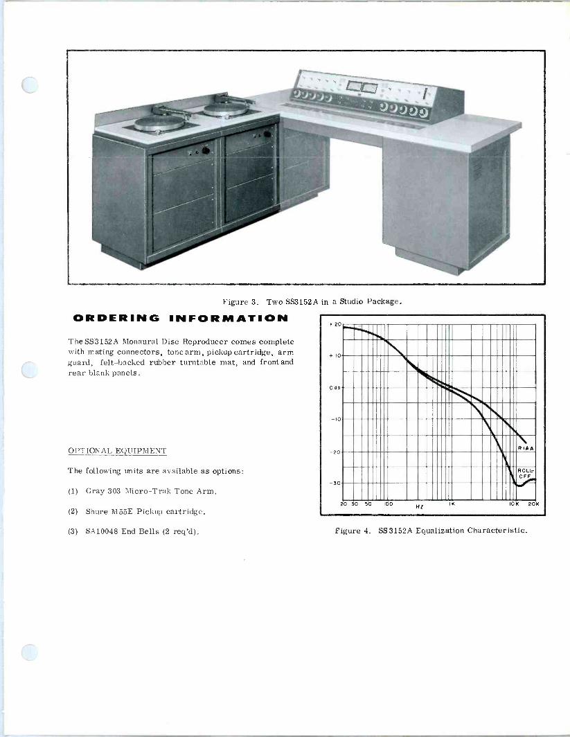
Figure 3. Two SS3152A in a Studio Package.
ORDERING INFORMATION The SS3152A Monaural Disc Reproducer comes complete with mating connectors, tone arm, pickup cartridge, arm guard, felt -backed rubber turntable mat, and front and rear blank panels.
OPTIONAL EQUIPMENT
The following units are available as options:
(1) Gray 303 Micro-Trak Tone Arm.
(2) Shure M55E Pickup cartridge.
(3) SA10048 End Bells (2 req'd). Figure 4. SS 3152A Equalization Characteristic.

SECTION: Turntables
Iss. 1; Mar '69
gM1M STEREO
'DESCRIPTION The SS3153A Stereo Disc Reproducer provides complete facilities for pro- fessional stereo reproduction of disc recordings. The SS3153A is completely self-contained with a CH12 three -speed turntable, viscous -damped tone arm, plug-in pickup cartridge, equalized pre- amplifiers, audio cue switching, and power supply. A unique system of shock mounting for the turntable, using heavy- duty rubber mounts and a system of balanced weights, reduces the top plate resonant frequency to approximately 4 hz and eliminates the effects of external vibration on the tone arm. The precision balanced tone arm permits tracking pressures as low as 1.5 grams.
The Block Diagram of the SS3153A shows the facilities provided. The standard tone arm is a Gray 'Micro-Trak' #303 fitted with a variable reluctance, stereo, professional -type, pickup cartridge. A
special feature of this arm is that it is damped in the horizontal direction only, to eliminate skating, while allowing free vertical movement on two jewel bear- ings. The cartridge outputs are equal- ized and amplified by AT131 preampli- fiers. Each AT131 incorporates aninput impedance selector for various types of cartridge, a gain control, and a roll -off circuit. A dual roll -cif selector is lo- cated on the cue panel and selects either RIA A equalization or extra roll -off at 10 khz for exceptionally noisy records.
The audio output is delayed slightly on turntable start to prevent starting 'wow'. The turntable may be started locally by means of the turntable speed control, or remotely by means of an external push- button or lever key. Motor start and cue pushbuttons, located on the cue panel,
IRiouw.Ltlaa l .Aao inousnu$ wurm
DISC REPRODUCER
SS3153A Disc Reproducer, with Optional End Bells Mounted
permit turntable control independent of the remote switch, and audio cue switching to an external bus with bypass of the audio delay cir- cuit.
The cabinet of the SS3153A presents a new approach to modular en- closures by McCurdy, ensuring harmony with other equipment and enabling buildup of the control room "package". The top is a lam- inated formica, ivory in color, and the cabinet is finished in tex- tured blue. An arm guard at the rear helps prevent accidental displacement of the tone arm. All audio, power, and control con- nections are accessible from the front of the unit behind a blank cover plate and are made via connectors which are provided as standard equipment (audio connectors are Cannon XLR types).
MCCURDY RADIO INDUSTRIES LIMITED 108 CARNFORTH ROAD o TORONTO 16 D CANADA
MCCURDY RADIO INDUSTRIES INCORPORATED 1051 CLINTON STREET C BUFFALO N.Y. 14206
I(416) 751-6262 TELEX 02-21660
I(716) 854-6700

CARTRIDGE
EQUALIZED PREAMPS
RIAA/ROLL OFF SWITCH
-14 AT13
24V0 - MOTOR
POWER SUPPLE
-0 TO ATI31
O 24V
-0 COMMON
KI
R
AT131 4
O (-6)
O-_+
1-6)
o t (-6) O vw
K2 /. 1
XLR-3-13 LEFT PGM OUTPUT -20DBM 60011
RIGHT PGM OUTPUT -2ODBM 60011
1 COMM CUE PB XL R-3-14 CUE OUTPUT OÌ O
I
-26DBM 60011
(1 117/230V A.C.
XLRR-44-13 r- START
--0 COMM MOTOR CUE
O O-
24V 0 seam 11
REMOTE START CONTROL
i ( NOT SUPPLIED)
Block Diagram of SS3153A
SPECIFICATIONS TURNTABLE DRIVE ASSEMBLY
(1) Speed Ranges: 33-1/3, 45, and 78 rpm.
(2) Speed Regulation: ±0.2% on all ranges.
(3) Noise and Rumble: Better than NAB reproducing standards, June 1953, Section 1.2.
(4) Flutter and Wow: Less than 0.17%.
(5) Power Requirement: 117v ac, 60 hz, single phase, 46 va (230v, 50 hz drives can be supplied).
ELECTRONIC ASSEMBLY
(1) Input Level: 5 mv, each preamplifier, via pin -type phone plug.
(2) Input Impedance: Variable from 10K to 75K ohms.
(3) Equalization: RIAA or extra high -frequency roll -off (see Curve).
(4) Frequency Response:
(a) Without roll -off filter; ±1 db of RIAA curve, 30 hz to 15 khz, ref 1 khz.
(b) Roll -off; Greater than 14 db below RIAA re- sponse at 10 khz.
(5) Output Levels:
(a) Program; -20 dbm nom, 0 dbm max, with 5 my input.
(b) Cue; -26 dbm nom, -6 dbm max.
(6) Output Impedance: 600 ohms, balanced.
(7) Distortion: Less than 0.5% at 0 dbm output, 30 hz to 15 khz, using reverse RIAA input network.
(8) Output Noise Level: AT131 input terminated with 510 ohms; -78 dbm nom, -60 dbm max.
(9) Stereo Separation: 70 db (less cartridge).
(10) Power Requirement: 117v ac, 50/60 hz, single phase, 35 va (may be strapped for 230v operation).
TONE ARM AND CARTRIDGE
(1) Arm: Gray 'Micro-Trak' Model 303, 12 -inch, with plug-in cartridge head.

(2) Cartridge: Shure M44C Stereo with 0.7 mil stylus. 22-1/2 in. (57.2 cm) deep. Each end bell (optional) adds 3/4 in. (1.9 cm) to width.
(3) Tracking Weight: Adjustable; weight kit supplied with tone arm.
GENERAL
(2) Ambient Temperature: 0 to 55°C.
(3) Finish: Cabinet; baked textured acrylic blue. Top; Formica Antique White.
(1) Overall Dimensions: 33-1/4 in. (84.5 cm) high, [29 in. (63.7 cm) to top of Formica], 22 in. (55.9 cm) wide, (4) Shipping Weight: 360 lb (163.3 kg) approx.
+ 20
+10
odo
10
20
30
RIAA
ROLL- OFF
20 30 50 100 HZ
IK I0K 20K
SS3153A Equalization Characteristic
ORDERING INFORMATION
The SS3153A Stereo Disc Reproducer is supplied com- plete with mating connectors, tone arm, stereo pickup cartridge, arm guard, 45 rpm adapter, felt -backed rubber turntable mat, and front and rear blank panels.
OPTIONAL EQUIPMENT
The following units are available as options:
(1) Gray 306 (16 in.) Micro-Trak Tone Arm.
(2) Shure M55E Pickup Cartridge.
(3) McCurdy AT264/3 Cue Amplifier/Speaker Kit.
(4) SA10048 End Bells (2 req'd).
32 3157E
monaural disc reproducer
hMcCue D

description & specifications The SS3157A Monaural Disc Reproducer provides facilities for professinoal monophonic reproduc- tion of monaural or stereo disc recordings. The SS3157A is completely self-cóntained with three - speed turntable, tone arm, plug-in pickup cart- ridge, equalized preamplifier, audio cue switching, and power supply.
The enclosed simplified diagram shows the facili- ties of the SS3157A. The turntable is the Mc- Curdy CH12A Transcription Turntable with speeds of 331/3, 45 and 78 rpm. The standard tone arm is a Micro Trak 303 utilizing a Stanton 500AL or Shure M44C professional -quality magnetic stereo cartridge. The cartridge output is equalized and amplified by an AT135 preamplifier which incor- porates an input load control (for various types of cartridge) and a roll -off selector. The roll -off selector is located on the control panel and selects either RIAA equalization or variable roll -off from 1 kHz to 16 kHz (see Curve). The roll -off amplitude is variable from zero to a maximum of 10 dB be- low RIAA between 10 kHz and 16 kHz.
The turntable start system may be set up for local operation by means of the turntable speed se- lector, or for remote operation by means of a lock- ing or two momentary ON/OFF pushbuttons, lever key, etc. There is also a MOTOR START push- button (momentary) for cueing independently of the normal start/stop circuits.
On remote operation, the audio output is delayed slightly on turntable start to prevent speed-up `wow'. This is accomplished by holding the mute relay (K1) energized until the turntable reaches operating speed, after which this relay deener- gizes and completes the audio output circuit. The delay is adjustable from 0.2 to 1.5 seconds, ap- proximately.
For instant cueing, a MOTOR START pushbutton and a CUE pushbutton permit bypassing the delay circuit so that the program output is immediately available, as well as the normal cue output. The cue output is taken from a combining network.
An optional AM275 3 Watt Cue Amplifier may be installed in the SS3157A.
The simplified diagram shows one of the AT135 Phono Preamplifiers in dotted outline as this would be provided only on the stereo model (SS3158A or SS3159).
The output and cue resistive pads, relay K1, and the power supply regulators are contained on one SM25 plug-in printed -circuit card. This card and the amplifiers plug into a prewired frame which also contains the power transformer and con- nector panel.
The basic cabinet of the SS3157A is finished in textured blue acrylic with wood -grain vinyl over- lays applied at points of extra wear such as the control panel and end bells. The top is of laminat- ed formica, ivory in color, with a tinted plexiglas guard at the rear to help prevent accidental dis- placement, of the tone arm. All audio and control connections are accessible at the front of the
unit, and are made via connectors which are pro- vided as standard equipment (audio connectors are Cannon XLR types).
SPECIFICATIONS
TURNTABLE
(1) Type: McCurdy CH12A; Capstan -Drive. (2) Speed Ranges: 331/3, 45, and 78 rpm. (3) Speed Regulation: ±0.2% on all ranges. (4) Noise and Rumble: Better than -35 dB ref 1.4
cm/sec peak velocity at 100 Hz.
(5) Flutter and Wow: Less than 0.17%. (6) Power Requirement: 117v ac, 60 Hz, single
phase, 46va (50 Hz drives can be supplied).
ELECTRONICS ASSEMBLY
(1) Input Level: 5 my nominal. (2) Input Loading: Variable from 10k to 250k. (3) Equalization: RIAA or roll -off at 16 kHz (see
Response Curve). (4) Frequency Response:
(a) Without roll -off; within 0.5 of RIAA curve from 30 Hz to 10 KHz.
±1 dB of RIAA curve, 10 KHz to 20 KHz.
(b) Roll -off; adjustable from 0 to 10dB below RIAA response between 10 kHz and 16 kHz (see Curve).
(5) Output Levels: (a) Program: adjustable -20 dBm to +8 dBm. (b) Cue: adjustable to +8 dBm.
(6) Output Impedance: 600 ohms, balanced. (7) Distortion: Less than 0.5% at +8 dBm output,
30 Hz to 20 kHz, using reverse RIAA input net- work.
(8) Power Requirement: 117v ac, 60 Hz, single phase, 50 va approximately.
TONE ARM AND CARTRIDGE
(1) Arm: Micro Trak 303. (2) Cartridge: Stanton 500AL or Shure M44C.
MECHANICAL
(1) Dimensions: 331/4 in. high (30 in. to top of Formica), 22 in. wide, 221/2 in. deep. Each end bell (optional) adds 3/4 in. to width.
(2) Finish: Baked textured acrylic blue, comple- mented by wood -grain vinyl overlay for added protection at points of abnormal wear.
(3) Weight: 90 lb., approx.
OPTIONAL EQUIPMENT
(1) Special Tone Arm, other than the standard (Shure SME 3009 and 3012, for example).
(2) AM275 Cue Amplifier. (3) SA10048 End Bells with vinyl overlay (2 req'd).
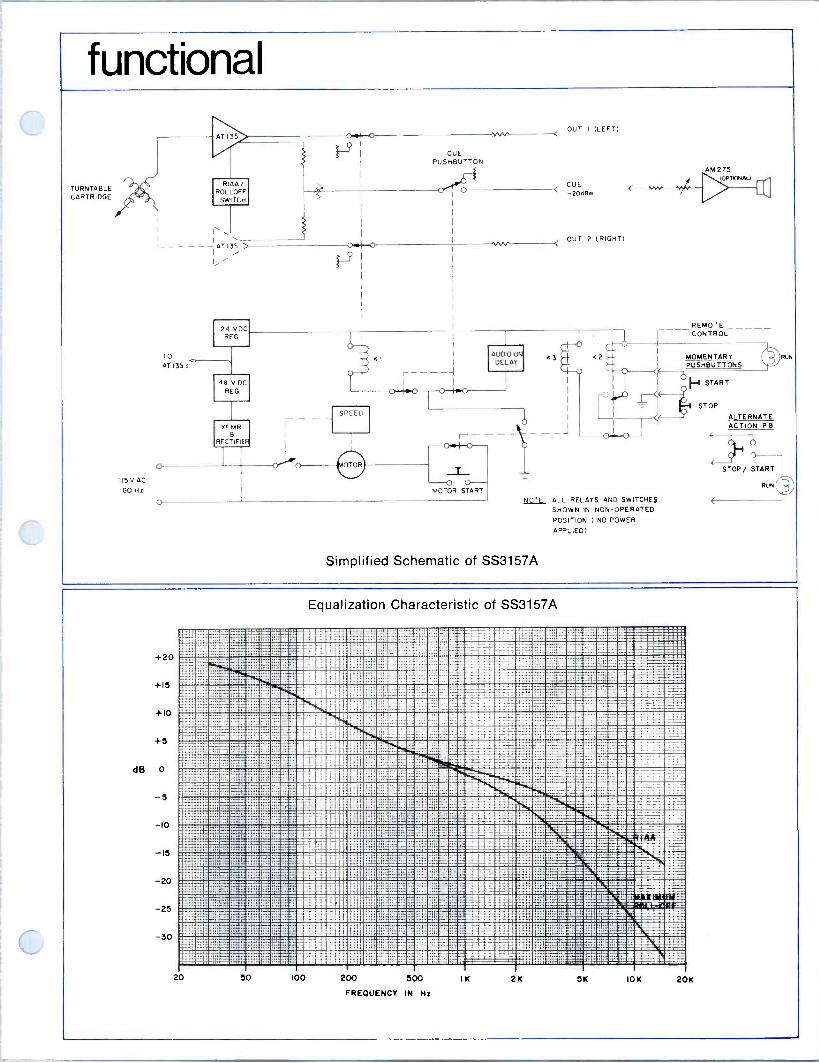
functional
TURNTABLE CARTRIDGE
115VAC
60Hz
I
I ----AT135 I i
TO
AT 135's
24 VDC REG
48 V DC REG
KFMR a
RECTIFIER
CUE PUSHBUTTON
OUT I (LEFT)
CUE -20dß.
OUT 2 (RIGHT)
KI
r ----I I I
AUDIO ON DELAY
SPEED
--- CY I C)
-T- -0 0 -- MOTOR START
AM 272 (OPT
--_ REMOTE CONTROL
AL)
K2 MOMENTARY I PUSHBUTTONS
START I, 9 -01
NOTE ALL RELAYS AND SWITCHES
SHOWN IN NON -OPERATED POSITION ( NO POWER
APPLIED)
Simplified Schematic of SS3157A
STOP
ALTERNATE ACTION PB
+20
+15
+10
+5
dB 0
-5
-IO
- I5
-20
-25
-30
Equalization Characteristic of SS3157A
:i =:::.:::i1;;147 122i EEiyi : iEe2r isçe;:"1:::1 96: . 7s!. Seic : i.iii..q.qáái 3C.- iiámx_r S=C . . sICZM;~=w
=5l3iiiiliiiiilúli7® ®ixäa:e°ssi='-z.2 ::i:::.:ï:iilsá';,zá : itis -'.- z::X:. :rai
!:;:;'.:i22:i1111ii1llll:il® ®: _:;.-::: ::::,Mffl x:,..iX...... ":' :ii 27'i...... i:-:iil11=iiliºii1!i11® i®®®®i"= --
c' " :11111i11llilli®®®®1®®®ZEIMMW :XX i#i. : i==:g.l in:eä':itilääM11liM!á1iIBIiIIi1®ZENIBEZZM =":='li.l111111iili!iiìil!NZ ZE®®W®ENIEZEIMM ¡Tile-. :i iiiï»^I:; s ilßiiiii.. a._ acX
:--LT. á sse 111 IiF: Er" sMENM ...........».S'1'."":IXC:..XX::TSj 1CC! ii i2xx: 3i12SiiL:t S J r:.x i_3353iiii eliEú,e
,.fiE iii iis7illrciiiiii!:Eéili6cE1nki=aálEZEZEZEREIMM 41. 3il31:iiiilliEi?"1Náullá41MEZ:EiE .
=1:M.i===i1i"=1i iié:ii.li:X` s: ,.p.... X:::.s
r r-:. ̂ ::.. 's:asr::u,?=eüü..ie:e.:i..i1.:x.: .i i,»:r ..Sil! a_ :ìs: l's x:m:. ._ ...
........ : . n.... .......iu31 =,==zz i......:.:::1. ;i. 3=e3:=:s.is..-.è..EiM_ s...»..........,....,,,.r.
`i .1.:: ,...,,, ...... r» t.s:::^::3:II:s -(s::r'_ç3 ':: :.......:::;í..».........:.a;e_scs r::»...._ _.»:. .........---
. . s:33r ..,,.__z 1es-:: ....,.aa"',.» g:i2:: ' _= 3r B r E .__ .., _ »,.... ......., _ r^-::::::éeezz:2sx2::s ::::.:....e......a:::::see ___ :=ii:. -i, stx=e=E m.==. . :,............. í.: ._. ... .-^ .. . .. :. ...............,..:._ -ssaü ^::»Fm»r;: ......x E...` i:22E3...s.. ?si::r.:sái1:. e_zs. s:::ss.. . ..... -
.ä-==aTiir: s5z iii::....:': :s : ::Ës: : e z__...»..zi:e ='e z. _m=--- z E
s -_i1 E2: 1 x
;_1 iilli:liliril
z6==
ié=5
;.--,-,-. s:t
z _..
mia i===1 -22E&í33
z
-m _,__. zc. l?izia_ z2Es::_::: :X pc:esae
í22e7x. 23E :333:::' . 3R3x=e_ . 23i.» ........,.....»... ,..,..,._E9 -:.. i:i. . ü °-i .3
i lr.'e'_.Ê r .:::1 e .. -i E ....
::X'2i::J: ........,i::i...
ilc= sssE.i2 ' j.
11tAirrff: i:=á -K,
2s=ffl? >='.: ae- . ssr- t::q _3_s
20 50 l0O 200 500
FREQUENCY IN H:
I 2K SK 10K 20K

ordering information SS3157A Monaural Disc Reproducer which comes complete with mating connectors, tone arm, pick- up cartridge, arm guard, felt -backed rubber turn- table mat, and front and rear blank panels.
The price for the standard SS3157A does not in- clude optional equipment nor the installation of optional equipment.
installation
i
30
r
111111111111 O O
22" 233"
Printed in Canada
McCURDY RADIO INDUSTRIES LIMITED 108 CARNFORTH ROAD, TORONTO, ONTARIO M4A 2L4 (416) 751-6262, TELEX: 06-963533
McCURDY RADIO INDUSTRIES INCORPORATED 1051 CLINTON STREET, BUFFALO, N.Y. 14206 (716) 854-6700, TWX 610-492-3219
EAST COAST OFFICE: SADDLE RIVER, N.J. P.O. BOX 86, ZIP 07458, PHONE (201) 327-0750, TWX 610-492-3219
McCurdy Radio industries reserves the right, without notice to make such changes in equipment, design, specifications, or components as progress in engineering or manufacturing techniques may warrant to improve the performance of the product.

32i2C stereo disc reproducer
letCul

description & specifications The SS3159C stereo disc reproducer provides com- plete facilities for professional stereo reproduction of disc recordings. The SS3159C is completely self- contained with a three -speed turntable, tone arm, plug-in pickup cartridge, equalized preamplifiers, audio cue switching and power supply. The enclosed simplified functional diagram shows the facilities of the SS3159C. The turntable used is the Panasonic Technics SP10 Mk II direct -drive transcrip- tion turntable with speeds of 331/3, 45 and 78 rpm. The standard tone arm is a Micro Trak 303 utilizing a Stanton 500AL or Shure M44C professional -quality stereo magnetic cartridge. The cartridge output is equalized and amplified by the AT235 preamplifiers which incorporate gain and equalizing trim controls along with selectable roll -off. The roll -off selector is located on the cue panel and selects either RIAA equalization or RIAA equalization with additional roll -off above 5kHz (3dB point).
The turntable start system may be set up for local operation by means of the turntable speed selector, or for remote operation by means of a locking or two momentary ON/OFF pushbuttons, lever key, etc. There is also a MOTOR START pushbutton (momentary) for cueing independently from the normal start/stop cir- cuits.
On remote operation, the audio outputs are delayed slightly on turntable start to prevent speed-up `wow'. This is accomplished by holding the mute relay (K1) energized until the turntable reaches operating speed, after which this relay de -energizes and completes the audio circuit. The delay is adjustable from approxi- mately 200ms to 1.5 seconds. For instant cueing, the MOTOR START pushbutton permits bypassing the delay relay, allowing immediate availability of the program output for local and/or remote cueing. Local cueing is available when the optional AM275 three Watt cue amplifier is installed. The REMOTE CUE output is used when it is desired to cue the turntable output via the cue position on a console input fader.
Relay KI, its associated delay circuit and the power supply regulators are contained on a plug-in printed circuit card.
To facilitate remote operation, using either a single alternate action (locking) or two momentary pushbut- tons, an interface is required to control the SP10 Mk II turntable. This is achieved by a logic circuit, also contained on a plug-in printed circuit card. The delay and regulator, control interface, preamplifiers and optional cue amplifier cards plug into a self- contained, prewired frame which also contains the power transformer, control relays and a connector panel. The basic cabinet of the SS3159C is finished in textured blue acrylic with wood -grain vinyl overlays applied at points of extra wear such as the control panel and end bells. The top is of laminated formica, ivory in colour, with a tinted plexiglass guard at the rear to help prevent accidental displacement of the tone arm. All audio and control connections are accessible at the front of the unit, and are made via connectors which are provided as standard equipment.
SPECIFICATIONS
TURNTABLE: TYPE: Panasonic Technics SP10 Mk II
DRIVE: Direct drive by brushless DC motor, quartz crystal controlled by phase lock servo circuit. SPEEDS: 331/3, 45 and 78.3 rpm, +_0.002%, up to a load of 4.3 lb. -in. (5 kg. cm.)
START-UP TIME: 0.25 sec. (25° rotation), maximum, to 331/3 rpm.
STOP TIME: 0.3 sec. (30° rotation), maximum, from 331/3 rpm to full stop.
WOW AND FLUTTER: 0.25% maximum, W.R.M.S. RUMBLE: -50dB (DIN A), -60dB (IEC B), -70dB (DIN B)
POWER REQUIREMENTS: 117 volts, 50/60Hz, single phase, 30 VA
ELECTRONICS ASSEMBLY:
INPUT LEVEL: 5 mV nominal INPUT IMPEDANCE: 47,000 ohms EQUALIZATION: Within +0.5dB of RIAA curve between 30Hz and 15kHz, or roll -off at 5kHz.
OUTPUT LEVELS: 1) Program; OdBm, 600 ohms, nominal, matching 2) Local Cue; OdBm, 600 ohms, nominal, bridging 3) Remote Cue; OdBm, 600 ohms, nominal, matching
OUTPUT IMPEDANCE: 600 ohms, active -balanced, program and cue outputs DISTORTION: 0.25% maximum, 30Hz to 15kHz, at +8dBm output POWER REQUIREMENTS: 117 Volts, 50/60 Hz, single phase, 40 VA
MECHAN ICAL:
OVERALL DIMENSIONS: 33.25 in. (84.5 cm) high, 30 in. (76.2 cm) to top of formica; 22 in. (55.9 cm) wide; 22.5 in. (57.2 cm) deep. Each optional end bell adds 0.75 in. (19 mm.) to width.
FINISH: Dark blue textured baked acrylic, complemented by wood -grain vinyl overlay for added protection at points of abnormal wear. WEIGHT: 200 lbs. (91 kg.), approximately
OPTIONAL EQUIPMENT: 1) Special tone arms as required; for example, Shure
SME3009 or SME3012. 2) SA10048 end bells with vinyl overlay, 2 required. 3) AM275 cue amplifier.

i

ordering information
The SS3159C stereo disc reproducer is complete with mating connectors, tone arm, pickup cartridge, arm guard, rubber turntable mat and front and rear blank panels. The price for the standard SS3159C does not include optional equipment nor the installation of optional equipment.
installation 7
33%
30"
O O
22a
2338 223
178 Printed in Canada
McCURDY RADIO INDUSTRIES LIMITED 108 CARNFORTH ROAD. TORONTO. ONTARIO M4A 2L4 (416) 751-6262, TELEX 06-963533, TWX 610-492-1373
McCURDY RADIO INDUSTRIES INC. UNITED STATES HEAD OFFICE
1711 CARMEN DRIVE, ELK GROVE VILLAGE, ILLINOIS 60007, (312) 640-7077, TWX 910-222-0436
EAST COAST OFFICE
223 WEST SADDLE RIVER ROAD, SADDLE RIVER, N.J. 07458, (201) 327-0750, TWX 710-988-2254
BUFFALO WAREHOUSE
1051 CLINTON STREET, BUFFALO, N.Y. 14206, DIRECT LINE TO TORONTO PLANT (716) 854-6700, TWX 610-492-1373
McCurdy Radio Industries reserves the right, without notice to make such changes in equipment, design, specifications, or components as progress in engineering or manufacturing techniques may warrant to improve the performance of the product.

direct drive turntable

description
The SP10 MKII turntable has been engineered specifically for high -quality audio applications. It offers the highest quality, lowest noise operation available today thus making it ideal for quality music applications. The turntable adds virtually nothing in the way of noise or wow and flutter to the audio recorded on the disc.
The SP10 MKII's electronically controlled brushless direct drive DC motor rotates at precisely the selected speed, eliminating all extraneous mechanical parts normally associated with turn- table drive systems. The absence of belts and idler wheels means there are few parts to wear out, with an attendant reduction of maintenance time and extension of useful life.
Rotational speed of the SP10 MKII is held to the extremely accurate tolerance ±.002% by the use of a quartz crystal oscillator as a frequency reference. This allows the motor speed to be controlled independently of environmental changes, such as temperature variations or fluctuations in power line voltage or frequency. Speed accuracy will be maintained even with wide variations in power line voltage.
Use of this electronic servo -controlled, direct -drive system assures that the wow and flutter will be less than .025%, weighted, RMS and start-up time will be very rapid. Running speed is reached in less than .25 sec, or 25° of turntable rotation, at 331/3 RPM, allowing accurate and immediate cueing. Speed changes, also, are accomplished very rapidly, taking no more than 0.4 sec. for the turntable speed to stabilize. The reference signal from the quartz oscillator is also used to power the neon lamp which illuminates the built-in stroboscope. Wave shaping by the strobe logic circuit gives a bright, clear strobe whose accuracy is independent of power line frequency fluctuations.
With the increasing demand for high quality standards, it is imperative that vertical as well as horizontal "rumble" be minimized. This "rumble" is generally caused. by the motor and drive system vibrations being transmitted to the turntable platter, and thus to the disc and pick-up stylus. The low -speed servo controlled motor of the SP10 MKII has the inherent advantage of very little vibration. Therefore, rumble figures exhibited by the SP10 MKII are better than -50dB (DIN weighting A),-60dB (IEC weighting B) and -70dB (DIN weighting B).
Additionally, the SP10 MKII has a non-magnetic, dynamically balanced, die-cast aluminum turntable platter whose 6.4 lbs of mass provides a strong speed -smoothing flywheel effect.
The SP10 MKII is manufactured to stringent broadcast specifications by Matsushita Electric Industrial Co. Ltd., and is sold under the "lbchnics" label.
specifications
TYPE: Direct drive. MOTOR: Ultra low speed brushless electronic
commutator DC. DRIVE SYSTEM: Quartz crystal controlled,
phase -locked electronic servo. SPEEDS: 331/3, 45 and 78.26 RPM. SPEED CHANGE METHOD: Electronic. SPEED ACCURACY: better than ±.002%. SPEED ACCURACY WITH VARYING LOAD:
0% up to a maximum load of 4.3 lbs in. (5 kg cm).
WOW and FLUTTER: less than .025% RMS, weighted
± .035% peak, weighted. RUMBLE: Better than -50dB (DIN A)
- 60dB (IEC B) - 70dB (DIN B)
STARTING TORQUE: 5.2 lbs in. (6 kg cm).
START-UP TIME: .25 sec. (25° rotation) to 331/3 RPM.
BRAKING TIME: .3 sec. (30° rotation) from 331/3 RPM to stop.
SPEED CHANGE TIME: .4 sec. from 331/3 to 78.26 RPM.
TURNTABLE PLATTER: Material: Dynamically balanced, die-cast
aluminum. Weight: 6.4 lbs (2.9 kg). Diameter: 1219/32 in. (32 cm). Moment of inertia: 130 lbs in2. (380 kg cm2).
DIMENSIONS: 41/64 in. H X1431/64 in. W X143 in. D. (10.25 cm X 36.85 cm X 36.85 cm)
WEIGHT: 20.9 lbs (9.5 kg). POWER REQUIREMENTS: 120V AC,
50/60Hz, 20W.
Mechanical brake circuit
Quartz oscillator
Speed change memory
Frequency divider circuit Strobe logic circuit
Drive circuit
Speed control circuit
Phase control circuit
Start/stop circuit
SP10 MKII Drive Electronics. The stable and highly accurate rotation of the SP10 MKII is
obtained with analog-digital circuitry using the latest electronic technology.
Automatic Electronic Speed Control _2

SP10 MKII DIRECT DRIVE TURNTABLE
performance characteristics
40dB
50
60
70
80
r iN\AK 1\10eii,A Y..
20 25 30 40 50 60 63 63 70 80 90 100 120 140 160 200
+0.0001%
+0.00005
o
- 0.00005
-0 0001
+0.05%
o
0.05%
FREQUENCY (Hz)
0 10 20 30
TIME (MINUTES)
40 50 60
McCurdy Radio Industries reserves the right without notice to make such changes in equipment, design, specifications, or components, as progress in engineering or manufacturing techniques may warrant, to improve the performance of the product.
FREQUENCY SPECTRUM OF RUMBLE
DRIFT CHARACTERISTICS
WOW AND FLUTTER CHARACTERISTICS
Printed in Canada SP1OMKII DIRECT DRIVE TURNTABLE / ISSUE 1/1,77
McCurdy Radio Industries Limited, 108 Carnforth Road,Toronto, Ontario M4A 2L4 (416) 751-6262 Telex: 06-963533
McCurdy Radio Industries Incorporated, TWX: 610-492-3219 1051 Clinton Street, Buffalo, N.Y. 14206 (716) 854-6700 Telex: 06-963533
U.S.A. East Coast Office, Saddle River, N.J. P.O. Box 86, 07458 (201) 327-0750

MR stereo disc reproducer
IMgC ui D
description & specifications The SS3159 Stereo Disc Reproducer provides complete facilities for professional stereo repro- duction of disc recordings. The SS3159 is com- pletely self-contained with two speed turntable, tone arm, plug-in pickup cartridge, equalized pre- amplifiers, audio cue switching, and power supply.
The enclosed simplified diagram shows the facil- ities of the SS3159. The turntable is the Panosonic SP1OD Direct Drive Transcription Turntable with speeds of 331/3 and 45 rpm. The standard tone arm is a Micro Trak 303 utilizing a Stanton 500AL or Shure M44C professional -quality magnetic stereo cartridge. The cartridge output is equalized and amplified by the AT135 preamplifiers which incorporate an input load control (for various types of cartridge) and roll -off selector. The roll - off selector is located on the cue panel and selects either RIAA equalization or variable roll -off from 10 kHz to 16 kHz (see Curve). The roll -off ampli- tude is variable from zero to 10 dB.
The turntable start system may be set up for local operation by means of the turntable speed selec- tor, or for remote operation by means of a lock- ing or two momentary ON/OFF pushbuttons, lever key, etc. There is also a MOTOR START push- button (momentary) for cueing independently of the normal start/stop circuits. On remote operation, the audio outputs is delayed slightly on turntable start to prevent speed-up `wow'. This is accomplished by holding the mute relay (K1) energized until the turntable reaches operating speed, after which this relay deener- gizes and completes the audio output circuit. The delay is adjustable from 0.2 to 1.5 seconds, ap- proximately.
For instant cueing, a MOTOR START pushbutton and a CUE pushbutton permit bypassing the delay circuit so that the program output is immediately available, as well as the normal cue output. The cue output is taken from a combining network.
An Optional AM275 3 Watt Cue Amplifier may be installed in the SS3159.
The output and cue resistive pads, relay K1, and the power supply regulators are contained on one SM28 plug-in printed -circuit card. This card and the amplifiers plug into a prewired frame - which also contains the power transformer and a connector panel.
The basic cabinet of the SS3159 is finished in textured blue acrylic with wood -grain vinyl over- lays applied at points of extra wear such as the control panel and end bells. The top is of laminat- ed formica, ivory in color, with a tinted plexiglas guard at the rear to help prevent accidental dis- placement of the tone arm. All audio and control connections are accessible at the front of the unit, and are made via connectors which are pro- vided as standard equipment (audio connectors are Cannon XLR types).
SPECIFICATIONS
TURNTABLE
(1)
(2)
(3)
(4)
(5)
(6)
(7)
Type: Panasonic SP -10-D, direct drive. Speed Ranges: 331/3 and 45 RPM. Speed Regulation: With varying load better than .15%. Variable Pitch Control: - 3% on all ranges. Wow and Flutter: Less than .03% RMS. Rumble: Better than
-50 db (DIN A) -55 dB (IEC B) -70 dB (DIN B)
Power Requirements: 120 V AC, 60 Hz.
ELECTRONICS ASSEMBLY
(1) Input Level: 5 my nominal. (2) Input Loading: Variable from 10k to 250k. (3) Equalization: RIAA or roll -off at 16 KHz (see
Response Curve). (4) Frequency Response:
(a) Without roll -off; within 0.5 dB of RIAA curve from 30 Hz to 10 KHz. ±1 dB of RIAA curve, 10 KHz to 20 KHz.
(b) Roll -off; adjustable from 0 to 10 dB below RIAA response at 16 KHz (see curve).
(5) Output Levels: (a) Program: adjustable -20 to +8 dBm. (b) Cue: adjustable to +8 dBm. Output Impedance: 600 ohms, balanced. Distortion: Less than 0.5% at +8 dBm output, 30 Hz to 20 KHz, using reverse RIAA input network.
(8) Power Requirement: 117 V AC, 60 Hz, single- phase, 50 va approximately.
(6) (7)
MECHANICAL
(1) Dimensions: 331/4 in. High (30 in. to top of Formica), 22 in. Wide, 221 in. Deep. Each end bell (optional) adds 3/4 in. to width.
(2) Finish: Baked textured acrylic; dark blue, complemented by wood -grain vinyl overlay for added protection at points of abnormal wear.
(3) Weight: 195 lbs., approx.
OPTIONAL EQUIPMENT
The following units are available as options: (1) Special Tone Arm if required by customer; for
example, Shure SME3009 or SME3012. (2) SA10048 End Bells with vinyl overlay (2 req'd).
(3) AM275 Cue Amplifier.

functional
TURNTABLE CARTRIDGE
115 VAC 60Hz
TO
AT135
O
O
24 VDC REG
CUE PUSHBUTTON
OUT I (LEFT)
CUE -2OdBm
F
OUT 2 (RIGHT)
48 V DC
REG
XFMR a
RECTIFIER ON/OFF
0
KI
SPEED
33i/45
'AUDIO ON K3 DELAY ----
I I I
0 Ieo o Ieo
I
I I----- lo
-0 0 -- MOTOR START
0
K2
-0I
NOTF.i ALL RELAYS AND SWITCHES
SHOWN IN NON -OPERATED POSITION ( NO POWER
APPLIED)
Simplified Schematic of SS3159
M4275 -. PTGNAU \
REMOTE CONTROL
MOMENTARY PUSHBUTTONS
I--1 START
STOP
ALTERNATE ACTION PB
STOP/ START
RUN
+20
-15
-20
-25
-30
Equalization Characteristic of SS3159.
20 50 t00 200 500
FREQUENCY IN Hz
IK 2K 5K
...,,,..,.IG
' ==Wh= E= Is.:lar"''
10K 20K

ordering information The SS3159 Stereo Disc Reproducer is complete The price for the standard SS3159 does not in - with mating connectors, tone arm, pickup cart- clude optional equipment nor the installation of ridge, arm guard, felt -backed rubber turntable optional equipment. mat, and front and rear blank panels.
installation
7
33%
I
30"
n
11101111111 0 0
22" 23h" 22W
Printed in Canada
McCURDY RADIO INDUSTRIES LIMITED 108 CARNFORTH ROAD, TORONTO, ONTARIO M4A 2L4 (416) 751-6262. TELEX: 06-963533
McCURDY RADIO INDUSTRIES INCORPORATED 1051 CLINTON STREET. BUFFALO, N.Y. 14206 (716) 854-6700, TWX 610-492-3219
EAST COAST OFFICE: SADDLE RIVER, N.J. P.O. BOX 86, ZIP 07458, PHONE (201) 327-0750, TWX 610-492-3219
McCurdy Radio Industries reserves the right, without notice to make such changes in equipment. design specifications, or components
as progress in engineering or manufacturing techniques may warrant to improve the performance of the product.

MOUNTING FRAME
DESCRIPTION The SA10004A equipment frame is designed to mount the McCurdy line of 1-3/4 inch plug-in amplifiers and trans- former modules in a standard 19 -inch EIA rack. The frame is of welded steel, partially -enclosed construction, which results in a lightweight rugged unit providing maximum ventilation.
The plug-in modules slide in between punched guide slots to mate with the connectors at the rear. A front cover, which attaches by means of two captive screws, presents an attractive appear- ance and carries a designation strip on its inner panel surface. External con- nections are made at the rear of the frame, which is fitted with a cable support platform. A protective cover is provided for the rear to prevent in- advertent contact with operating voltages.
SPECIFICATIONS
OVERALL DIMENSIONS
1-3/4 in. (4.45 cm) high, 14-3/4 in. (37.46 cm) deep, 19 in. (48.26 cm) wide.
FINISH
Textured medium blue and iridite.
INSTALLED WEIGHT (less modules)
6 lb (2.72 kg).
SECTION: Accessories
Iss. 1; Nov '68
ORDERING INFORMATION ORDER
SA10004A Mounting Frame (Includes connectors)
ACCOMMODATE S
Up to 12 single -width modules, such as AT240A, MT244, or MT245, each 1-3/16 in. wide (3.02 cm).
Up to 6 double -width modules, such as AT242, each 2-3/8 in. wide (6.03 cm).
Combinations of the above as long as total width does not exceed that of 12 single modules.
MCCURDY RADIO INDUSTRIES LIMITED 108 CARNFORTH ROAD o TORONTO 16 o CANADA
MCCURDY RADIO INDUSTRIES INCORPORATED 1051 CLINTON STREET o BUFFALO o N.Y. 14206
I(416) 751-6262 TELEX 02-21660
(716) 854-6700

14\11eYPA7
MOUNTING FRAME
DESCRIPTION The SA10007 Mounting Frame is designed for mounting in a standard EIA 19 -inch rack and occupies 5-1/4 inches of rack space. The unit is of welded open -frame construction to provide adequate ventila- tion, yet is extremely rigid.
The frame acc ommodates the MRI series of plug-in modules which slide in between guide rails and mate with the Blue -Ribbon connectors at the rear of the frame. The standard frame is supplied with sufficient guide rails to accommodate eight single - width modules, but these may be re- arranged as required to receive any module -width combination within the width required for eight single units.
External connections are made at the rear of the Blue -Ribbon connectors; a solder -terminal strip is also located on a platform at the rear to provide additional tie -points. An MRI accessory mounting tray can be bolted to the rear platform to accommodate relays, filters, etc.
SPECIFICATIONS
ORDERING INFORMATION ORDER: SA10007 Mounting Frame
OPTIONAL ACCESSORY: C4000T/5-19 Accessory Mounting Tray, 2-1/4 in. w by 16-7/8 in. lg.
ACCOMMODATES OVERALL DIMENSIONS Eight single modules, such as ÁT305, each 2-1/8 in. wide
5-1/4 in. h, 15-5/8 in. d, 19 in. w
FINISH Dark blue metallic
Four double modules, such as PS874, each 4-1/4 in. wide
Two quadruple modules, such as AM430, each 8-1/2 in. wide
INSTALLED WEIGHT (less modules) Any combination of the above, as long as total width does not 13 lb exceed that of eight single modules.
MCCURDY RADIO INDUSTRIES LIMITED TORONTO CANADA

CZ2
prewired jackfields
D
description The SA10100S Series of Prewired Jackfields consist of a standard rack mounting strip, containing 24 type 239A tip -ring -sleeve jacks, wired to a terminal block having 5 rows of 24 terminals each. The first four rows terminate the jack springs, with the fifth row strapped vertically and reserved for shield and ground termination. Since all springs are wired to the block, cross-jumpering and circuit changes may be accomplished without soldering directly on the jacks.
A designation strip is included on the jack assembly, and mounting bars for the terminal block are provided as standard equipment. One pair of mounting bars will accommodate four terminal blocks.
Four cable layouts are available; these are used when more than one terminal block is mounted on a set of
f
SA IOK -2O-4 4
LA IOICO -d
3
bars, and are designated SA10100S-1, -2, -3, and -4. (See Cable Layout). In large jackfields, after the -4 block is used, the -1 may be repeated, etc.
A similar jackfield (SA10100) is available with un- shielded cable. This should be used only where levels in adjacent cables are the same, so that the danger of crosstalk if minimized. Accessory patch cords are available in the following lengths:
Patch Cord No.
SA10131 SA10132 SA10133 SA10136
BA ,0100-2 2
_A IOI00-I Po5.I
J A C K f I e L
JACK 01 TO I/A/S/C/D JACK 2 To 2/A/8/C/D JACK 24. To 24/A/8/C/D N. a SHIELDS ARE CONNECTED AT JACK SLEEVE e TERMINAL 'E' OF TERMINAL BLOCK. THE 'E' TERMINALS ARE NOT CONNECTED To EACH OTHER.
Length
12 inches 24 inches 36 inches 72 inches
TeRIAATIo1J 13Loc c 5
McCURDY RADIO INDUSTRIES LIMITED
CCURDY 108 CARNFORTH ROAD, TORONTO, ONTARIO M4A 2L4 (416) 751-6262, TELEX: 06-963533
McCURDY RADIO INDUSTRIES INCORPORATED 1051 CLINTON STREET, BUFFALO, N.Y. 14206 (716) 854-6700, TWX 610-492-3219
EAST COAST OFFICE: SADDLE RIVER, N.J. P.O. BOX 86, ZIP 07458, PHONE (201) 327-0750, TWX 610-492-3219
McCurdy Radio Industries reserves the right, without notice to make such changes in equipment, design, specifications, or components as progress in engineering or manufacturing techniques may warrant to improve the performance of the product.

gÄ-1CYLAg
PRE -WIRED JACKFIELD
DESCRIPTION
The SA-1O100S Pre -Wired Shielded Jack - field provides maximum convenience and eliminates time consuming, detailed field wiring to provide rapid, trouble -free install- ations. The SA -101005 units consist of 24 tip, ring -sleeve jacks wired complete with normals to a standard telephone block. The jackfields (illustrated right) fit standard 19" mounting, and terminal block mount- ing bars are included with each jackfield.
McCurdy Pre -Wired Jackfields are supplied in four positions with tailored cable dress progressively longer to permit the terminal blocks to automatically locate in correct sequence behind the jacks. Where maxi- mum access to the rear of jacks is desired, the jackfield is available with an extra 4 - foot length of cable (Model SA -10100S -A). McCurdy also offers shielded patch cords in 2, 3, and 6 foot lengths.
The terminal block supplied is a 26 row "A" block with 5 terminals per row. Ter- minals are designated A, B, C, D and E. The jack is wired: Tip to terminal A; Ring to terminal B; Tip -spring to terminal C; Ring -spring to terminal D and all sleeves and shields are wired to terminal E.
ORDERING INFORMATION
SPECIFY: model number of McCurdy Pre -Wired Jackfield (or accessory) desired. When ordering more than one unit for mounting in single rack, please note that positions 1, 2, 3
and 4 indicate progressively longer cable lengths (i.e., Position 4 is longest and 1 is basic unit).
BASIC PARTS and ACCESSORIES
SA -10100S Pre -Wired 24 Jack Strip wired to 5 x 26 telephone block
SA -10100S -A Same as SA -101005 except with additional 4 -ft cable length
SA -10102
SA -10132
SA -10133
SA -10136
Unwired 24 -Jack Strip (using 239A Single Jacks)
2 -Foot Shielded Patch Cord (equipped with 310 plugs)
3 -Foot Shielded Patch Cord (equipped with 310 plugs)
6 -Foot Shielded Patch Cord (equipped with 310 plugs)
McCURDY RADIO INDUSTRIES INCORPORATED (617) 774-6411
57 N. PUTNAM ST. DANVERS MASS. D 01923
gÄlCA2C) SERIES MODULAR ENCLOSURES
DESCRIPTION The SA10040 Series of Modular Enclo- sures provides versatility and conven- ience in mounting avariety of equipments. Two basic types of enclosure are avail- able; the SA10040 Pedestal and the SA10042 Housing, as shown in Fig. 1 and 3. All enclosures are of rugged steel con- struction and finished in MRI textured blue. For cable entry, knockouts are provided in the base of each unit, with additional knockouts in the side panels of the SA10042. Since there is no bottom panel in either unit, cabling may also be brought up through the floor.
SA10040 PEDESTAL
The SA10040 pedestal is adaptable to accommodate panel -mounted equipment and a turntable or tape unit. The basic pedestal consists of a rugged framework providing 22-3/4 inches of rack space for 19 -inch wide panels (See Fig. 1 and 2). When fitted with one of the adapter tops, the SA10040 matches various MRI console desks both in dimensions and color scheme. The following accessory units are available, as shown in Fig. 2:
(1) SA10041 Tape Recorder Adapter. This is a sloped housing which accom- modates 19 -inch panels and may be used for tape units or control panels (see Fig. 1 and 2). The front of the SA10041 adapter is hinged to the SA10040 pedestal so that it maybe tilted forward for serv- icing. The back of the SA10041 is louvered for ventilation.
Figure 1. SA10040 Pedestal with SA10041 Tape Recorder Adapter.
(2) SA10045 Turntable Mounting Board. The SA10045 allows mount- ing an MRI type CH12 turntable (custom cutouts for other types can be made on special order). The mounting board is made of wood laminated with white Formica. The total thickness is 1-5/8 inches to provide optimum damping effect.
MCCURDY RADIO INDUSTRIES LIMITED (416) 751-6262 108 CARNFORTH ROAD p TORONTO 16 O CANADA TELEX 02-21660
MCCURDY RADIO INDUSTRIES INCORPORATED (716) 854-6700
1051 CLINTON STREET o BUFFALO o N.Y. 14206
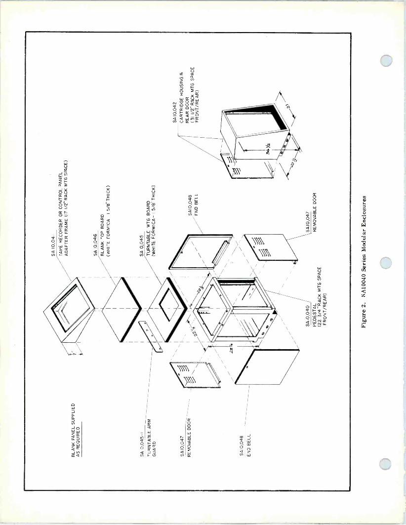
á o Ó a Ln
O ó á

(3) SA10045-1 Turntable Arm Guard. This guard is made of 1/8 -inch anodized aluminum and fits behind the turntable mounting board. It is useful to prevent accidental playback arm displacement.
(4) SA10046 Blank Top. The blank top fits in place of the SA 10045 and is constructed of the same materials.
(5) SA10047 Removable Doors. The doors may be used to cover the front and rear of the pedestal, when equipment panels are not used. They are louvered to allow ventilation of the interior. Installation and re- moval are simplified by the use of a single quick - fastener on each door.
(6) SA10048 End Bells. Used to close the sides of the pedestal when it is not butted against other equip- ment. Each end bell is secured by one quickfastener.
SA10042 CARTRIDGE TAPE HOUSING
The SA10042 provides 31-1/2 inches of vertical rack space in an attractive sloped -front cabinet. This can be used to house cartridge tape machines or 19 -inch equipment panels (See Fig. 3). The panels may be mounted front or rear, but rear mounting will not permit installation of the door; the removable rear door is provided as standard equipment.
BLANK PANELS
Figure 3. SA10042 Cartridge Tape Housing.
Where the 19 -inch wide equipment panels do not utilize all the vertical space in the SA10040 or SA10042, it is desirable to fill in empty areas with blank panels. Panels of the following heights are available:
SA11021: 1-3/4 in. SA11025: 8-3/4 in. SA11022: 3-1/2 in. SA11026: 10-1/2 in. SA11023: 5-1/4 in. SA11027: 12-1/4 in. SA11024: 7 in.
ORDER units and accessories by type number and name.

U\1©22ü EQUIPMENT RACKS
DESCRIPTION The SA10410 and SA10420 Equipment Racks combine strength and versatility to meet a wide variety of installation requirements. Each type of rack pro- vides 77 inches of vertical mounting space for 19 -inch wide panels, the only difference in the two models being the front - to - rear dimension which is 22 inches for the SA10410 and 25- 1/2 inches for the SA10420 (see dimensional diagram). The racks are of all -welded construction; the framework is ruggedly formed of 12 -gauge C.R. steel to accom- modate the heaviest of rack -mounting units, with side panels and doors of 18 - gauge steel.
The most outstanding features of these racks are the results of design tech- niques that achieve flexibility in use:
Basic rack can be used where side panels or doors not required.
Side panels and doors easily installed or removed without the use of tools, providing the ultimate in installation ease and equipment accessibility.
Doors can be mounted front and/or rear, to open from left or right, and can be fitted with locks.
Mounting angles for equipment panels may bepositioned for flush or recess mounting at front or rear, or for attachment to both front and rear of equipment (see detail photo).
Two or more racks may be bolted together for perfectly -aligned mul- tiple installations. Specially -formed crossbraces with welded spacers ensure positive joins without danger of distortion.
Ventilation by convection may be provided by a perforated top panel which is available as an optional extra. Included as standard equip- ment is a full-length plugmold strip, with twelve ac outlets, through which ac power can be supplied to the rack -mounted units. In addition, a convenience outlet is installed at the bottom front of the rack for test equipment, etc.
Installation dimensions are shown in the dimensional diagram. The weight of the basic framework is 110 lb. ; add 32 lb. for each side panel and 30 lb. for each door required. A complete line of blank panels from 1-3/4 inches to 12 inches is available(see Catalog Price List). The standard rack finish is blue vinyl, but other finishes are available on request.
MCCURDY RADIO INDUSTRIES LIMITED 108 CARNFORTH ROAD TORONTO ONTARIO M4A 2L4
MCCURDY RADIO INDUSTRIES INCORPORATED 1051 CLINTON STREET BUFFALO N.Y. 14206
(416) 751-6262 TELEX 02-21660
(716) 854-6700

The height of 77 inches provides for 44 rack units (a rack unit = 1-3/4 inches); the mounting holes are spaced to accommodate any combination of one -unit panels and multiples thereof.
Each side panel adds 1 inch to the width of the basic rack; each door adds 1-1/4 inch not including the handle, which protrudes another 1-5/8 inch.
The rack may be fastened to the floor by means of the four mounting holes provided in the base flange, if desired. The recommended fasteners are 3/8 -inch by 4 -inch lag screws. However, the rack is adequately stable for normal stationary installations without bolting down.
MOUNTING ANGLE RACK 1
POSITIONING SLOTS
SECURING HARDWARE
MOUNTING ANGLE RACK 2
CROSSBRACES- SEPARATED BY
WASHERS
77
I- - 22 g I
B2
22
h..--22 g
BASIC RACK DIMENSIONS (INCHES)
T 25 2
OR
22
L
Shown here are two racks bolted together; the units are joined at all three crossbraces although only one join is shown here. The welded -on, 1/8 -inch thick washers take the full stress of assembly and keep the strain off structural members, thereby ensuring a rigid, positive join without any distortion of framework, panels, etc.
The mounting angles may be positioned anywhere from extreme front and rear to center. However, where a door is installed, 1/2 inch allowance must be made for the door closing. Also, if the equipment next to the door has knobs or other protrusions, further allowance must be made for these.
No. 12-24 speednuts and bolts are provided for simple, easy installation of the angles to any of the holes in the crossbraces. In addition to this positioning, the mating cutouts in the angles are 1 -inch slots to permit exact positioning.
ORDERING INFORMATION ORDER
SA10410 Equipment Rack (22 in. deep) OR
SA10420 Equipment Rack (25-1/2 in. deep)
(All hardware included).
OPTIONAL ACCESSORIES
See Catalog Price List for: (1) Side panels (2) Doors (3) Rack Top (4) >3Iank panels
McCurdy Radio Industries reserves the right, without notice, to make such changes in equipment, design, specifications, or components as progress in engineering or manufacturing techniques may warrant to improve the performance of the product.

gMl© © EQUIPMENT RACKS
DESCRIPTION The SA10410 and SA10420 Equipment Racks combine strength and versatility to meet a wide variety of installation requirements. Each type of rack pro- vides 77 inches of vertical mounting space for 19 -inch wide panels, the only difference in the two models being the front - to - rear dimension which is 22 inches for the SA10410 and 25 -1/2 inches for the SA10420 (see dimensional diagram). The racks are of all -welded construction; the framework is ruggedly formed of 12 -gauge C.R. steel toaccom- modate the heaviest of rack -mounting units, with side panels and doors of 18 - gauge steel,
The most outstanding features of these racks are the results of design tech- niques that achieve flexibility in use:
Basic rack can be used where side panels or doors not required.
Side panels and doors easily installed or removed without the use of tools, providing the ultimate in installation ease and equipment accessibility.
Doors can be mounted front and/or rear, to open from left or right, and can be fitted with locks.
Mounting angles for equipment panels may be positioned for flush or recess mounting at front or rear, or for attachment to both front and rear of equipment (see detail photo).
Two or more racks may be bolted together for perfectly -aligned mul- tiple installations. Specially -formed crossbraces with welded spacers ensure positive joins without danger of distortion.
Ventilation by convection may be provided by a perforated top panel which is available as an optional extra. Included as standard equip- ment is a full-length plugmold strip, with twelve ac outlets, through which ac power can be supplied to the rack -mounted units. In addition, a convenience outlet is installed at the bottom front of the rack for test equipment, etc.
Installation dimensions are shown in the dimensional diagram. The weight of the basic framework is 110 lb.; add 32 lb. for each side panel and 30 lb. for each door required. A complete line of blank panels from 1-3/4 inches to 12 inches is available(see Catalog Price List). The standard rack finish is blue vinyl, but other finishes are available on request.
MKURDY RADIO INDUSTRIES LIMITED TORONTO CANADA

The height of 77 inches provides for 44 rack units (a rack unit = 1-3/4 inches); the mounting holes are spaced to accommodate any combination of one -unit panels and multiples thereof.
Each side panel adds 1 inch to the width of the basic rack; each door adds 1-1/4 inch not including the handle, which protrudes another 1-5/8 inch.
The rack may be fastened to the floor by means of the four mounting holes provided in the base flange, if desired. The recommended fasteners are 3/8 -inch by 4 -inch lag screws. However, the rack is adequately stable for normal stationary installations without bolting down.
MOUNTING ANGLE RACK 1
POSITIONING SLOTS
SECURING HARDWARE
MOUNTING ANGLE RACK 2
CROSSBRACES- SEPARATED BY
WASHERS
77
1-4-- 228
821 4
1 I-- 19é -Hi
22
H- 22 8
BASIC RACK DIMENSIONS (INCHES)
25 2 OR
22
Shown here are two racks bolted together; the units are joined at all three crossbraces although only one join is shown here. The welded -on, 1/8 -inch thick washers take the full stress of assembly and keep the strain off structural members, thereby ensuring a rigid, positive join without any distortion of framework, panels, etc.
The mounting angles may be positioned anywhere from extreme front and rear to center. However, where a door is installed, 1/2 inch allowance must be made for the door closing. Also, if the equipment next to the door has knobs or other protrusions, further allowance must be made for these.
No. 12-24 speednuts and bolts are provided for simple, easy installation of the angles to any of the holes in the crossbraces. In addition to this positioning, the mating cutouts in the angles are 1 -inch slots to permit exact positioning.
ORDERING INFORMATION ORDER
SA10410 Equipment Rack (22 in. deep) OR
SA10420 Equipment Rack (25-1/2 in. deep)
(All hardware included).
OPTIONAL ACCESSORIES
See Catalog Price List for: (1) Side panels (2) Doors (3) Rack Top (4) Blank panels

modular enclosure
D

description & specifications
I7Z X 19" STD. SPACE
124 X 19" STD. SPACE
208
WHITE FORMICA
SHELF
17"
FOUR SWIVEL CASTERS
(OPTIONAL)
-4
I
171" 2
1 8° ANGLE
J
WHITE FORMICA ON TOP
3
SIDE
2 IDEP7H)
,-3X 2 KNOCK OUT I - (BOTH END)
3
22;
REAR DOOR
L12 X 16 OPEN BOTTOM
L3 8
1
3S
The SA10044 is another in the Series of Modular Enclosures providing versatility and convenience for mounting a variety of equipment. Designed specifically for cartridge tape machines, several different mounting arrangements may be chosen to place equipment in a convenient operating po- sition while maintaining an all over attractive ap- pearance. 171/2 -Inches of rack space for 19 -inch panels is provided in the top section at an 10° angle, 121/4 -inches is available at the bottom. These enclosures are of rugged steel construc- tion and finished in MRI textured blue. For cable entry, knockouts are provided in the base of the unit. Since there is no bottom panel, cabling may also be brought up through the floor. The SA10044 auxiliary housing comes complete with panel mounting hardware and a rear door.
ACCESSORIES
Where the 19 -inch wide equipment panels do not utilize all the vertical space in the SA10044, it is desirable to fill in empty areas with blank panels. Panels of the following heights are available: SA11021: 13/4 in. SA11025: 83/4 in. SA11022: 31/2 in. SA11026: 101/2 in. SA11023: 51/4 in. SA11027: 121/4 in. SA11024: 7 inches. ORDER units and accessories by type number and name.
178 Printed in Canada
McCURDY RADIO INDUSTRIES LIMITED 108 CARNFORTH ROAD. TORONTO. ONTARIO M4A 2L41416) 751-6262, TELEX 06-963533, TWX 610-492-1373
McCURDY RADIO INDUSTRIES INC. UNITED STATES HEAD OFFICE
1711 CARMEN DRIVE, ELK GROVE VILLAGE, ILLINOIS 60007, (312) 640-7077, TWX 910-222-0436 EAST COAST OFFICE
223 WEST SADDLE RIVER ROAD, SADDLE RIVER, N.J. 07458, (201) 327-0750, TWX 710-988-2254 BUFFALO WAREHOUSE
1051 CLINTON STREET, BUFFALO, N.Y. 14206, DIRECT LINE TO TORONTO PLANT (716) 854-6700, TWX 610-492-1373
McCurdy Radio Industries reserves the right, without notice to make such changes in equipment, design, specifications, or components as progress in engineering or manufacturing techniques may warrant to improve the performance of the product.

?'1
extended -range audio level meter
D
description & specifications The SA14021A Extended -Range Audio Level Meter is a self-contained, solid-state instrument designed for the measurement of audio system transmission levels in dbm. The SA14021A can accommodate audio input levels from -50 dbm to +30 dbm (sine wave) with zero meter reading. A front panel switch selects two ranges, -50 dbm to +10 dbm and -30 dbm to +30 dbm, and a calibrated attenuator provides fine selection in 2 db steps within these ranges. Two balanced inputs are provided, one for 600 ohms matching and the other for 20,000 ohms bridging. A high impedance output permits monitoring by headset without affecting the meter reading.
Range: Two ranges, in 2 db steps, for zero indication: (1) -50 to +10 dbm (2) -30 to +30 dbm
Input Impedance: (1) 600 ohms matching, balanced, 10% (2) 20,000 ohms bridging, balanced
Frequency Response: Within 0.5 db, 20 hz to 20 khz
Distortion: (at +30 dbm input): (1) Less than 1%, 50 hz to 15 khz (2) Less than 1.5% 20 hz to 20 khz
Signal-to-noise ratio: Better than 40 db below any full-scale reading
An amplifier and a power supply circuit are mounted on printed -circuit boards inside the instrument cabinet. These circuits are all solid-state, with silicon devices used throughout for maximum reliability. The cabinet is designed for standard 19 -inch rack mounting and occupies only 5-1 /4 inches of rackheight. The front panel hinges forward to permit access to internal components and mounts the operating controls, input and monitoring jacks, and a 4-1 /2 inch meter. External power connections are made by plugging the line cord into the required ac source. A terminal board is mounted on the rear of the unit for making extension connections to remote jacks if desired.
Attenuator Tracking: Within 0.25 db per step (non -accumulative) Meter Ballistics: Complies with audio level meter standards Monitor Output: 0.15 volt into 20,000 -ohm headset Power Requirements: 105 to 125 v/210 to 230 v ac, 50/60 hz, single phase, 5 va approx Dimensions: 5-1 /4 in. (13.33 cm) high, 5-1/4 in. (13.33 cm) deep, 19 in (48.26 cm) wide Weight: (1) Shipping:15 lb (6.8 kg) (2) Installed:13 lb (5.9 kg)
ordering information ORDER SA14021A Extended -Range Audio Level Meter; specify line voltage and frequency
ACCESSORIES (not supplied)
(1) SA10132 two -foot patch cord (2) SA10133 three-foot patch cord (3) SA10136 six-foot patch cord
McCURDY RADIO INDUSTRIES LIMITED
CURDY 108 CARNFORTH ROAD, TORONTO, ONTARIO M4A 2L4 (416) 751-6262, TELEX: 06-963533
McCURDY RADIO INDUSTRIES INCORPORATED 1051 CLINTON STREET, BUFFALO, N.Y. 14206 (716) 854-6700, TWX 610-492-3219
EAST COAST OFFICE: SADDLE RIVER, N.J. P.O. BOX 86, ZIP 07458, PHONE (201) 327-0750, TWX 610-492-3219
McCurdy Radio Industries reserves the right, without notice to make such changes in equipment, design, specifications, or components as progress in engineering or manufacturing techniques may warrant to improve the performance of the product.

3A 1©1 EXTENDED -RANGE AUDIO LEVEL METER
DESCRIPTION
The SA14021A Extended -Range Audio Level Meter is a self-contained, solid- state instrument designed for the meas- urement of audio system transmission levels in dbm. The SA14021A can ac- commodate audio input levels from -50 dbm to +30 dbm (sine wave) with zero meter reading. A front panel switch selects two ranges, -50 dbm to +10 dbm and -30 dbm to +30 dbm, and a cali- brated attenuator provides fine selec- tion in 2 db steps within these ranges.
Two balanced inputs are provided, one for 600 ohms matching and the other for 20,000 ohms bridging. A high impedance output permits monitoring by headset without affecting the meter reading.
An amplifier and a power supply circuit are mounted on printed -circuit boards inside the instrument cabinet. These circuits are all solid-state, with silicon devices used throughout for maximum reliability. The cabinet is designed for standard 19 -inch rack mounting and occupies only 5-1/4 inches of rackheight. The front panel hinges forward to permit access to internal components and mounts the operating controls, input and mon- itoring jacks, and a 4-1/2 inch meter.
SECTION; Accessories
Iss. 1; Mar '69
External power connections are made by plugging the line cord into the required ac source. A terminal board is mounted on the rear of the unit for making extension connections to remote jacks if desired.
MCCURDY RADIO INDUSTRIES LIMITED 108 CARNFORTH ROAD c TORONTO 16 o CANADA
I(416) 751-6262 TELEX 02-21660
1051 CLINTON STREET en BUFFALO c N.Y. 14206
MCCURDY RADIO INDUSTRIES INCORPORATED (716) 854-6700
s?`

SPECIFICATIONS RANGE ATTENUATOR TRACKING
Two ranges, in 2 db steps, for zero indication: Within ±0.25 db per step (non -accumulative)
(1) -50 to +10 dbm (2) -30 to +30 dbm
INPUT IMPEDANCE
(1) 600 ohms matching, balanced,±10% (2) 20, 000 ohms bridging, balanced
FREQUENCY RESPONSE
Within ±0.5 db, 20 hz to 20 khz
METER BALLISTICS
Complies with audio level meter standards
MONITOR OUTPUT
0.15 volt into 20, 000 -ohm headset
POWER REQUIREMENTS
105 to 125 v/210 to 230 v ac, 50/60 hz, single phase, 5 va approx
DISTORTION (at +30 dbm input) DIMENSIONS
(1) Less than 1%, 50 hz to 15 khz 5-1/4 in. (13.33 cm) high, 5-1/4 in. (13.33 cm) (2) Less than 1. 5% 20 hz to 20 khz deep, 19 in (48.26 cm) wide
WEIGHT SIGNAL-TO-NOISE RATIO
(1) Shipping: 15 lb (6.8 kg)
Better than 40 db below any full-scale reading (2) Installed: 13 lb (5.9 kg)
ORDERING INFORMATION ORDER
SA14021A Extended -Range Audio Level Meter; specify line voltage and frequency
ACCESSORIES (not supplied)
(1) SA10132 two -foot patch cord (2) SA10133 three-foot patch cord (8) SA10136 six-foot patch cord
McCurdy Radio industries reserves the right, without notice, to make such changes in equipment, design, specifications, or components as progress in engineering
or manufacturing techniques may warrant to improve the performance of the product.

ET3
)Ü
stereo cartridge tapes
A VUST FOR STEREO OPERATIONS
hMgCur (dgr
description Through remarkable new design achievements, Aristocart cartridge tapes approach the perfor- mance and fidelity of reel-to-reel equipment. Aristocarts meet or exceed all applicable NAB Specifications. Consistent phase relationship ensures complete mono/stereo compatibility (maximum loss is less than 3 dB at 12 kHz). Wow and flutter are minimized by a unique design in which part of the tape acts as a mechanical filter. A new guide arrangement reduces strain and wear, thus greatly increasing tape and transducer life.
Guide design and careful assembly procedures also help to maintain the special uniformity char- acteristic between Aristocart cartridges. Mounted in Lexan shatterproof housing.
Also available are optically -aligned sweep fre- quency alignment cartridges with rapid sweep from 50 Hz to 15 kHz.
*The amazing new Aristocart Cartridge Tapes are now wound and distributed by McCurdy Radio Industries.
unit price loaded empty
TIME 1-99 100-249 250-499
20 sec. $3.45 $3.25 $3.00 1- 99 2.90 40 sec. 3.30 3.25 3.05 100-249 2.70 63 sec. 3.60 3.40 3.15 250-499 2.50 70 sec. 3.60 3.40 3.15 500-999 2.40
100 sec. 3.70 3.50 3.25 1000 -up 2.30 21/2 min. 3.80 3.55 3.35 31/2 min. 4.00 3.75 3.50 4/ min. 4.05 3.90 3.65 5/ min. 4.15 4.05 3.80 71/2 min. 4.65 4.35 4.10 81/2 min. 4.80 4.50 4.25
10 min. 5.00 4.70 4.40
For other times use price of next highest time given.
Sizes may be assorted for quantity pricing. Alignment cartridge sweeps frequencies from 50 Hz to 15 kHz.
Printed in Canada
5% Discount on 250-499 price for quantities of 500 to 999
10% Discount on 250-499 price for quantities of 1000 up
McCURDY RADIO INDUSTRIES INCORPORATED 1051 CLINTON STREET, BUFFALO, N.Y. 14206 (716) 854-6700
McCurdy Radio Industries reserves the right, without notice to make such changes in equipment, design, specifications, or components as progress in engineering or manufacturing techniques may warrant to improve the performance of the product.

1MtCueg price list
erfedive
Februdr 1979
McCURDY RADIO INDUSTRIES INC. UNITED STATES HEAD OFFICE
1711 CARMEN DRIVE, ELK GROVE VILLAGE, ILLINOIS 60007 (312) 640-7077 TWX 910-222-0436
EAST COAST OFFICE 223 WEST SADDLE RIVER ROAD, SADDLE RIVER, N.J. 07458 (201) 327-0750 TWX 710-988-2254
McCURDY RADIO INDUSTRIES LIMITED 108 CARNFORTH ROAD, TORONTO, ONTARIO M4A 2L4 (416) 751-6262 TELEX 06-963533, TWX 610-492-1373
SUPERSEDES PRICE LIST OF FEBRUARY, 1978
State and Local Taxes excluded.
Prices shown F.O.B. Plant
Shipping by Surface Freight unless otherwise specified.
Prices Subject to Change without notice.
model description unit price
SS3159
SPIOMK II
SH -10B3
SL-1000MK II
S L-1500 M K I I
AT235
SA236-P2
AM275
TM40-12FR
SA10048
SA10545
S220
881-S
D81
D681 EEE
D6800 E E E
681 SE
D6800S E
500AL
D5107AL
TURNTABLES AND ACCESSORIES
Stereo Disc Reproducer, with Cabinet, Electronics and SPIOMK Il Turntable (Less End Bells and Cartridge)
Ultra -Fidelity Direct Drive Turntable without Tone Arm
Base for SP -10M K I l
Quartz Controlled Direct Drive Turntable with Titanium Tone Arm and Obsidian Base
Ultra -Fidelity Direct Drive Turntable with Tone Arm
Equalized Phono Preamplifier; -20 to +8 dBm, 600 OHMS
Stereo Phono Preamp. Package c/w Housing, Power Supply and Two AT235 Preamps
3 Watt Cue Amplifier for S53159 Turntable Assembly
12" Felt/ Rubber Mat for Turntables
End Bell (2 required) for SS3159 Turntable
45 RPM Adapter
Syntec 12" Tone Arm
Stanton Cartridge; 1 Gram Tracking
Stylus for 881-S Cartridge
Stanton Cartridge; 34 to 11/2" Gram Tracking
Stylus for 681 EEE Cartridge
Stanton Cartridge; 2 to 4 Grams Tracking Force
Stylus for 681 SE Cartridge
Stanton Cartridge; 3 to 7 Gram Tracking
Stylus for 500AL Cartridge
3,135.00
900.00
350.00
1,400.00
390.00
215.00
600.00
165.00
20.00
35.00
2.00
85.00
90.00
45.00
54.00
27.00
43.20
19.40
15.00
7.20
1

model description unit price
AT249
AT284
AT284A
AT285
AT286
CP287
AT288
AT291
AT297
AT299
AT310
RG311
AT313
AT313 /150
A M 484
AM487
AM487R
SYSTEM AMPLIFIERS
Distribution Amplifier (Six Outputs)
Console Mic Preamplifier; -60 dBm
Console Mic Preamplifier; -70 dBm
Console Matching Input Module; -20 dBm
Console Bridging Input Module; 0 dBm
Console Mic A.G.C. Preamplifier
Console Bridging Input Module; +8 dBm
Console Program Module
Console Program Module
Console Program Module
Distribution Amplifier (Twenty -Two Outputs)
Distribution Ampl. (AT310) c/w Remote Gain
Universal Ampl. with Eight, 600 OHM Output Splits (FR906)
Universal Ampl. with Two 150 OHM Output Splits (FR906)
Monitor Ampl. 20 W, 8 OHM Transformerless Output (FR905)
Monitor/ Distribution Ampl., 20 W, Transformer Output (FR905)
Monitor/ Distribution Ampl., 20 W, Transformer Output with Remote Gain (FR905)
195.00
100.00
125.00
100.00
100.00
165.00
125.00
165.00
195.00
215.00
200.00
320.00
325.00
390.00
600.00
660.00
750.00
2

model description unit price
D75
D150A
AT265
DC300A
AM415
AM481
AM482
AM483
MT483-1
BT483-1 A
RG483-2A
AM484
A M 487
AM487-R
MONITOR AMPLIFIERS
Dual Channel 30 Watt Amplifier Dual Channel 75 Watt Amplifier
3 Watt Mini -Cue Amplifier/Speaker; Rack Mounting
Dual Channel 150 Watt Amplifier 10 Watt Self Powered Amplifier 15 Watt Power Amplifier 15 Watt Amplifier c/w Remote Gain
60 Watt Amplifier, Self Powered (Frame: FR905)
Matching Input XMR for AM483
Briding Input XMR for AM483
Remote Gain Card for the AM483
Monitor Ampl., 20 W, 8 OHM, Transformerless Output (FR905)
Monitor/DA 20 Watt, Self Powered (Frame: FR905)
Monitor/DA, 20 Watt, Self Powered with Remote Gain (FR905)
369.00
549.00
200.00
899.00
150.00
190.00
310.00
520.00
50.00
50.00
110.00
600.00
660.00
750.00
PS849
PS852
PS853
PS854
PS855
PS856
PS859
PS876A/48
POWER SUPPLY Linear 48 Volt, 1 Amp Unreg. (FR904)
Bipolar 15 Volt, 3 Amp (FR906)
Bipolar 15 Volt, 3 Amp (FR905)
Bipolar 25 Volt, 3 Amp (FR905)
Bipolar 25 Volt, 2 Amp (FR906)
Linear 24 Volt, 4 Amp (FR906)
Linear 48 Volt, 2 Amp. Reg.; 24 Volt, 1 Amp Reg. (FR905)
Linear 48 Volt, 1 Amp Reg.; 24 Volt, 250 MA Reg. (FR903)
225.00
360.00
360.00
P.O.R.
390.00
390.00
550.00
325.00
3

model description unit price
CS9100
CS9200
AP176
A P276
XP177
XP277
AM478T
PS852
CD4016
INTERCOM SYSTEMS AND ACCESSORIES 10 x 10 Balanced Intercom System c/w All Input and Output Amplifiers, Crosspoints and Power Supply (One Frame 51/4")
20 x 20 Balanced Intercom System c/w All Input and Output Amplifiers, Crosspoints and Power Supply (Three Frames 153/4")
Input Ampl. with no Crosspoints
Input Ampl. with All Crosspoints
No Preamp, Otherwise same as AP176
No Preamp, Otherwise same as AP276
Two Output Amps, +18 dBm and 3 Watts at 8 OHMS
Power Supply ± 15 Volts
Dual X -Pt Chips
6,000.00
16,445.00
230.00
255.00
110.00
130.00
225.00
360.00
5.00
DA504
DA505
DA506
DA507
AUDIO DISTRIBUTION SYSTEMS Audio Distribution Assembly c/w: - Six Amplifiers, Each with 22 Outputs Max. - Power Supply (PS855) - Prewired and Tested in a 51/4" Frame (FR906)
Audio Distribution Assembly c/w: - Six AM487, Each with 75 Outputs Max. - Mounted in a FR905 Frame
Audio Distribution Assembly c/w: - Six AT313 Amps, each with 22 Outputs Max. - One PS855 Power Supply - Mounted in a FR906 Frame
Stereo Audio Distribution Assembly c/w: - Six Stereo Distribution Amps (AT394) - One PS855 Power Supply - One FR906 Frame
1,790.00
4,260.00
2,510.00
2,315.00
4

model description unit price
SS4312
SS4386A
SS4388A
SS8400
SS8500
RC700
DC8481
DC8481 L
DC8482
DC8483
DC8484
DC8485
7601
AUDIO CONSOLES AND ACCESSORIES 12 Mixer, Dual Channel, Monophonic Desk Mounting Console
6 Mixer, Single Channel, Monophonic Desk Mounting Console
8 Mixer, Single Channel, Monophonic Desk Mounting Console
12 Mixer, Dual Channel Modular Monophonic Free Standing Console
10 Mixer, Stereo Modular Console, Free Standing
NOTE: Series 8550, 8600, 8650, 7800 and 7900 Consoles for Air, Production and Recording are priced separately.
Dual Pedestal Console Mounting Desk with Arborite Top and Recessed Control Tray
Single Push Button Remote `Start' Switch for Console Desk c/w Panel
Single Alternate-Action Push Button `Start' Switch for Console Desk c/w Panel
Two Push Button Remote `Start -Stop' Switch for Console Desk c/w Panel
Three Push Button Remote Control Switch for Console Desk c/w Panel
Two Push Button Remote `Start -Stop' Switch for Console Dsk with Space in Center
Five Push Button Remote Control Switch for Console Desk c/w Panel
Script Board Assembly for Consoles
8,950.00
4,750.00
3,975.00
P.O.R.
P.O.R.
1,100.00
40.00
40.00
60.00
75.00
65.00
110.00
250.00
5

model description unit price
FR905
F R905-5
FR906
FR906-1
FR906-5
F R906-6
F R906-7
AMPLIFIER FRAMES AND ACCESSORIES Mounting Frame for Extrusion Modules 51/4" Rack Space
Amphenol Conn., Cover and All Mounting Hardware for Installing P.S. and Other AC Operated Equipment (AM483,487) in FR905 Frame
Mounting Frame for Universal Cards 51/4" Rack Space
Extender Card for FR906
Amphenol Connector, Cover and All Mounting Hardware for Installing Power Supplies in FR906 Frame
72 Pine Wire -Wrap Connector and Mounting Hardware for FR906 Frame
72 Pine Solder -Eye Connector and Mounting Hardware for FR906 Frame
140.00
20.00
140.00
50.00
20.00
10.00
10.00
SA10900S
SA10902
S A 10131
SA10132
SA10133
SA10134
SA10136
Cl 0900 / 5-1
B10900/5-23
JACKFIELDS AND PATCH CORDS
Prewired Shielded Jackfield (Positions 1, 2, 3 and 4)
Unwired Jackfield
One Ft. Patch Cord
Two Ft. Patch Cord
Three Ft. Patch Cord
Four Ft. Patch Cord
Six Ft. Patch Cord
JKF'D Mounting Bar
JKF'D Swivel Bracket Assembly
250.00
115.00
13.00
14.00
15.00
16.00
17.00
10.00
10.00
6

model description unit price
SA10040
SA10041
SA10045
SA10045-1
SA10046
SA10047
SA10048
SA10080
SA10086
SA10088
SA10030
SA10030-1
SA10043
SA10044
SA10044-1
SA10044-2
SA10044-3
SA10044-4
SA10044-8
MODULAR ENCLOSURES
Pedestal
Tape Machine Adapter Frame
Turntable Mounting Board
Turntable Arm Guard
Blank Top Board
Removable Door
End Bell
Jumbo Pedestal
Blank Top Board
End Bell
R.P. Housing for SA10080 Series
3D Housing for SA10080 Series
Desk Mounting Cartridge - Tape Machine Housing
Floor Mounting Cartridge - Tape Machine Housing c / w Rear Door
Rack Mounting Frame for 2 - 3D Series Machines
Rack Mounting for RP Series Machine or 2 - SP Series Machines
Blank Panel to Cover Area when only 1 - 3D Machine is Housed in the SA10044-1
Blank Panel to Cover Area when Only 1 - SP Machine is Housed in the SA10044-2
Blank Panel to Cover Area Above WRA Series Machine when Mounted in SA10044-2 Beside the 3D Machine
175.00
125.00
70.00
15.00
55.00
35.00
35.00
265.00
95.00
40.00
200.00
150.00
250.00
325.00
60.00
55.00
11.00
11.00
10.00
SA10410
SA10411
SA10412
SA10413
SA10414
SA10420
SA10421
SA10423
EQUIPMENT RACKS
22" Deep Equipment Rack c/w Rear Rails, AC Plugmold and Duplex Box
Side Panel for 22" Deep Rack
Door Assembly (Front or Rear) for 22" and 251/2" Deep Racks
Top for 22" Deep Equipment Rack
Plugmold for 22" or 251/2" Deep Racks
251/4" Deep Equipment Rack c/w A/C Plugmold Duplex Box and Rear Rails
Side Panel for 251/2" Equipment Rack
Top for 251/2" Deep Rack
350.00
50.00
85.00
20.00
45.00
370.00
55.00
20.00
7

model description unit price
SA11021
SA11022
SA11023
SA11024
SA11025
SA11026
SA11027
12-107
12-108
12-109
BLANK PANELS
13/4" Blank Panel
31/2" Blank Panel
51/4" Blank Panel
7" Blank Panel
83/4" Blank Panel
101/2" Blank Panel
121/4" Blank Panel
7" Deep Recess Bracket for Above Panels
51/4" Deep Recess Bracket for Above Panels
31/2" Deep Recess Bracket for Above Panels
7.00
8.00
9.00
10.00
11.00
12.00
13.00
10.00
9.00
8.00
4301 WX
4301 EWX
4311 WX
4313 W X
4315WX
LSA609
SA137A
SA137A-01
SA137A-06
SA137A-07
SA138A
SA138A-2
SA138A-01
SA138A-05
PROFESSIONAL SPEAKER SYSTEMS
Broadcast Monitor
Amplified Broadcast Monitor
Control Monitor, Oiled Walnut
Control Monitor, Oiled Walnut
Compact Studio Monitor, Oiled Walnut 4 -Way
10 -Watt Speaker/Amplifier Assembly
168.00
P.O.R.
336.00
369.00
906.00
325.00
CLOCKS AND COUNTERS
Counter, Main Chassis
Display Panel
Counter Control Panel (Console Mount)
Counter Control Panel (Desk Mount)
Clock Main Chassis
Display Panel for Clock Main Chassis
Display Panel for Console
Crystal Option for Clock
475.00
220.00
165.00
180.00
200.00
165.00
195.00
85.00
8

model description unit price
EQ155D EQ8491
EQ8492
622A
622B
672A
501
701
418A
8000A 9000 BD955 BD955
F L201
FL201-03 2830
2830-03 H910
H910-02 H910-03 H910-04 H910-05
245E
516EC
LA -4A DR -3A SR -3A
1176LN DR -21
SR -21
111B
PROCESSING EQUIPMENT
Variable Equalizer Variable Equalizer 71/2"
Variable Equalizer 61/2"
Single Channel Parametric Equalizer Dual Channel Parametric Equalizer 622 Options - Option 01: Transformer - Balanced Output (Indicate
whether Single or Two Channel) - Option 02: Eliminates Built-in AC Power Supply Equalizer Kepex c/w Panel
Gain Brain c/w Panel
Stereo Compressor/ Limiter Optimod-FM Compressor/Limiter/Stereo Generator Optimod-AM Compressor/Limiter Broadcast Digital Delay; 6.4 Sec. at 7.5KHz Broadcast Digital Delay; 6.4 Sec. at 15KHz Stereo Connection Flanger Balanced in/out XMR. Coupling Omnipressor Balanced in/out XMR Coupling Harmonizer Digital Pitch Ration Readout Balanced in/out XMR. Coupling Extra Variable Delay Output 2 -Octave Phase Locked Keyboard - Mono, Ctl's. one way Stereo Sythesizer Dynamic Sibilance Controller Compressor/ Limiter Double Rack Mount for Two LA-3A's or LA -4's Single Rack Mount for One LA -3A or LA -4
Peak Limiter Double Rack Mount for Two LA -5's Single Rack Mount Dual Channel Echo Chamber
400.00 435.00 435.00 479.00 749.00
499.00 313.00 313.00 795.00
3,195.00 3,995.00 3,900.00 6,300.00
100.00 615.00 50.00
600.00 40.00
1,500.00 125.00 40.00
240.00
500.00 349.00 629.00
396.00 14.00 18.00
488.00 14.00 18.00
695.00
9

model description unit price
SA141
SA143
OT156
OT157B
SA14023
4930
RG408-4
M R1-1007
5522
M R1 -502-M
M R1- 502-S
PJ660-5
SA618
A -M RI -7-69 & A -M RI -9-20
A-MRI-7-75 & A -M RI -9-30
19-02
M D421 U
MZW421
M D441 U
MZW441
R L500
BROADCAST ACCESSORIES Mono Tape Input Switcher with Line Outputs and Cue Speaker
Stereo Tape Input Switcher with Line Outputs and Cue Speaker
Oscillator
Variable Oscillator
Extended Range VU Meter
Can of MRI Blue Touch -Up Paint
AM408 Plug -In Tube Replacement
1500 MFD, 75 Volt Capacitor
Replacement Lamp 30V-40MA Schadow
P & G Mono Attenuator
P & G Stereo Attenuator
ADC Xmas Tree Terminal Block
Warning Light Relay Assembly Less Relays (Each Relay is $60.00)
71/2" Blank Panel and Excutcheon for 7400 Console
4" Blank Panel and Escutcheon for 7400 Rmt. Ctl. Tray
McCurdy 2 -Conductor Shielded Cable per 1000 ft.
Sennheiser Dynamic Microphone with Low Z Cable
Windscreen
Sennheiser Dynamic Microphone with Low Z Cable
Windscreen
Scully and MCI Reel to Reel Housing with Overbridge and Casters (For Full Track or Two Track)
550.00
825.00
165.00
415.00
600.00
6.00
50.00
5.00
1.75
175.00
250.00
25.00
175.00
10.00
8.00
100.00
300.00
20.00
418.00
24.00
395.00
10

MIgCLudg
SUPERSEDES PRICE LIST OF JANUARY 1976 a QflCC e Mary 19//

1
model description unit price
TURNTABLES AND DISC REPRODUCERS
SP10 MKII Technics Direct Drive Turntable with servo speed control system; 33-1/3, 45, ARPM
$ 700.00
CH12A 12" Transcription Turntable; 3 -speed (Rim drive) 435.00
SS3157 Monaural Disc Reproducer, with cabinet, electronics and CH12A Turntable (less End Bells) 1,865.00
SS3159A Stereo Disc Reproducer with cabinet, electronics and SP10MKII Turntable (less End Bells) 2,585.00
TURNTABLE ACCESSORIES
IW-CH12 Idler Wheel for CH12A 16.00
DB-CH14 Drive Belt for CH14 16.00
AT235 Equalized Phono Preamplifier -20 dBm to +8 dBm nominal output 193.00
SA236-P1 Consists of Housing with Power Supply and one AT235 Equalized Phono Preamplifier; output level -20 dBm to +8 dBm nominal (selectable) 352.00
SA236-P2 Consists of Housing with Power Supply and two AT235 Equalized Phono Preamplifiers; output level -20 dBm to +8 dBm nominal (selectable) 544.00
AM275 3 Watt Cue Amplifier for SS3157 and SS3159A Turntable Assembly 150.00
TM40-12FR 12" Felt/Rubber mat for CH12A and SP10 MKII Turntables 17.00
SA10048 End Bell (2 req'd) for Disc Reproducers 30.00
SA10545 45 RPM Adapter for CH12A and SP10 MKII Turntables 1.00
303 12" Tone Arm 85.00
75932 Head Shell for 303 Tone Arm 14.50
75961 Weight Kit for 303 Tone Arm 3.48
500AL Stanton Cartridge 15.00
D5107AL Stylus for 500AL 8.00
681EEE Stanton Cartridge 50.00
D6800EEE Stylus for 681 EEE 25.00
AMPLIFIERS
AT249 Distribution Amplifier (six outputs) 193.00
AT265 3 -Watt Mini -Cue Amplifier/Speaker; rack mounted 204.00
AT284 Console Mic Preamplifier input module (-60 dBm, 150 ohms) 100.00
AT284A Console Mic Preamplifier input module (-70 dBm, 150 ohms) 105.00
AT285 Console Matching input module (-20 dBm, 600 ohms) 100.00
AT286 Console Bridging input module (0 dBm, 20K ohms) 100.00
CP287 Console Mic Preamplifier input module with AGC 165.00
AT288 Console Bridging input module (+8 dBm, 40K ohms) 122.00
AT291 Console program module 165.00
AT297 Console program module 195.00
AT299 Console program module 215.00
AT310 Distribution Amplifier (twenty-two outputs, max.) 204.00
RG311 Distribution Amplifier (AT310) with Remote Gain 303.00

model description unit price
MONITOR AMPLIFIERS
D60 Dual Channel Monitor Amplifier (30 watts per channel) 299.00 D150A Dual Channel Monitor Amplifier (75 watts per channel) 499.00 DC -300A Dual Channel Monitor Amplifier (150 watts per channel) 849.00 AM415 10 watt self powered Amplifier 149.00
AM481 15 watt Power Amplifier 193.00
RG482 15 watt Power Amplifier with Remote Gain 303.00 AM483 60 watt self powered Amplifier 523.00
MT483-1 Matching input Transformer for the AM483 50.00
BT483-1A Bridging input Transformer for the AM483 50.00
RG483-2A Remote Gain card for the AM483 110.00
POWER SUPPLIES
PS814 Bipolar 15 Volt, 150 mA (FR904) frame) 193.00
PS824R Linear 24 Volt, 500 mA regulated (FR904 frame) 138.00
PS848B Linear 48 Volt, 1 Amp. regulated, linear 24 Volt, 250 mA, regulated (FR904 frame) 303.00
PS849 Linear 48 Volt, 1 Amp. unregulated (FR904 frame) 193.00
PS851 Linear 5 Volt, 6 Amp. regulated (906 frame) P.O.R.
PS852 Bipolar 15 Volt, 6 Amp. (FR906 frame) 303.00
PS853 Bipolar 15 Volt, 3 Amp. (FR905 frame) 358.00 PS854 Bipolar 25 Volt, 3 Amp. (FR905 frame) 435.00 PS855 Bipolar 25 Volt, 2 Amp. (FR906 frame) 385.00 PS856 Linear 24 Volt, 4 Amp. (FR906 frame) 385.00 PS857 Linear 24 Volt, 6 Amp. (FR905 frame) 495.00 PS858 Linear 24 Volt, 1 Amp. (FR906 frame) P.O.R.
PS859 Linear 48 Volt, 2 Amp. regulated, 24 Volt, 1 Amp. regulated (FR905 frame) 435.00
PS876A/48 Linear 48 Volt, 1 Amp. regulated; linear 24 Volt, 250 mA. regulated (FR903 frame) 292.00
INTERCOM SYSTEMS
CS9100 10 x 10 Balanced Intercom System c/w all input amplifiers, output amplifiers, crosspoints and power supply. One frame 51/4". 4,950.00
CS9200 20 x 20 Balanced Intercom System c/w all input amplifiers, output amplifiers, crosspoints and power supplies. Three frames (153/4" total) 13,950.00
CS9300 30 x 30 Balanced Intercom System c/w all input amplifiers, output amplifiers, crosspoints and power supplies. P.O.R
2
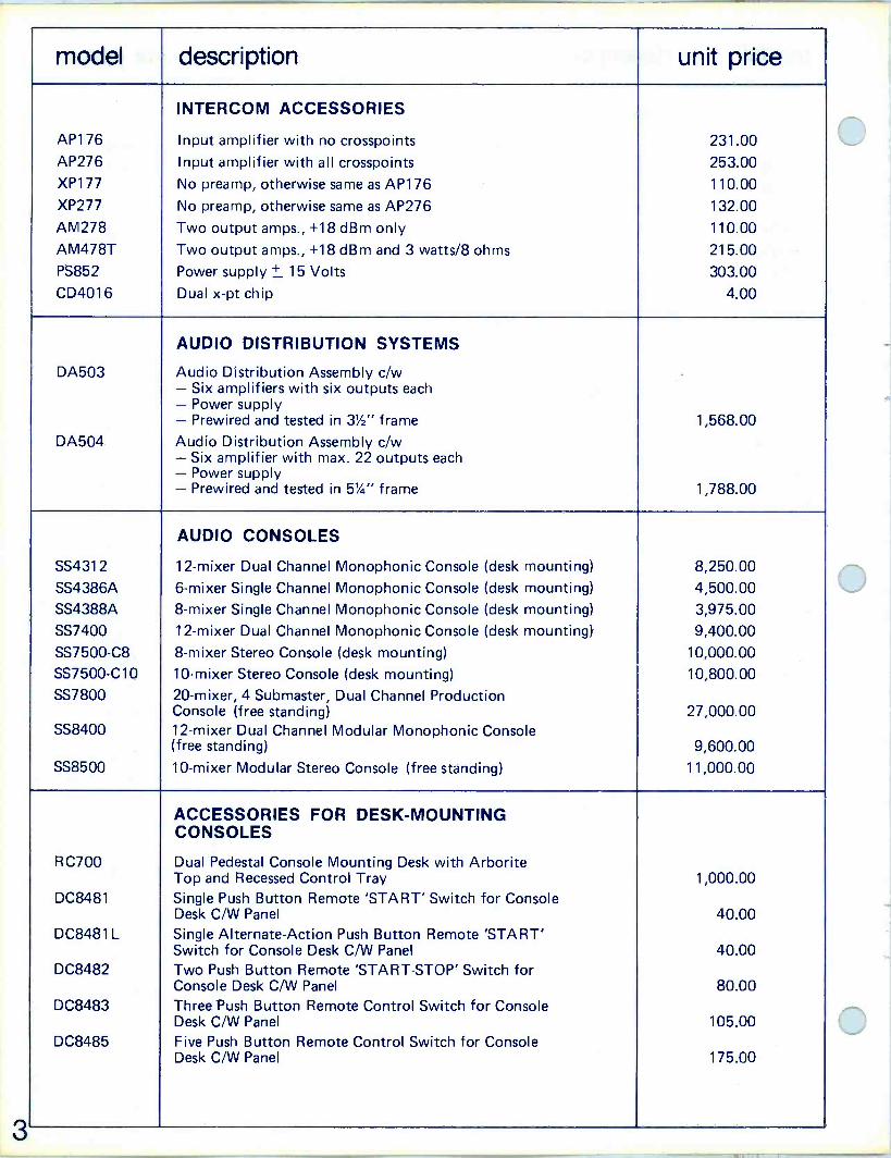
3
model description unit price
INTERCOM ACCESSORIES
AP176 Input amplifier with no crosspoints 231.00 AP276 Input amplifier with all crosspoints 253.00 XP177 No preamp, otherwise same as AP176 110.00 XP277 No preamp, otherwise same as AP276 132.00 AM278 Two output amps., +18 dBm only 110.00
AM478T Two output amps., +18 dBm and 3 watts/8 ohms 215.00 PS852 Power supply + 15 Volts 303.00 CD4016 Dual x -pt chip 4.00
AUDIO DISTRIBUTION SYSTEMS
DA503 Audio Distribution Assembly c/w - Six amplifiers with six outputs each - Power supply - Prewired and tested in 31/2" frame 1,568.00 DA504 Audio Distribution Assembly c/w - Six amplifier with max. 22 outputs each - Power supply - Prewired and tested in 51/4" frame 1,788.00
AUDIO CONSOLES
SS4312 12 -mixer Dual Channel Monophonic Console (desk mounting) 8,250.00 SS4386A 6 -mixer Single Channel Monophonic Console (desk mounting) 4,500.00 SS4388A 8 -mixer Single Channel Monophonic Console (desk mounting) 3,975.00 SS7400 12 -mixer Dual Channel Monophonic Console (desk mounting) 9,400.00 SS7500-C8 8 -mixer Stereo Console (desk mounting) 10,000.00 SS7500-C10 10 -mixer Stereo Console (desk mounting) 10,800.00 SS7800 20 -mixer, 4 Submaster, Dual Channel Production
Console (free standing) 27,000.00 SS8400 12 -mixer Dual Channel Modular Monophonic Console
(free standing) 9,600.00 SS8500 10 -mixer Modular Stereo Console (free standing) 11,000.00
ACCESSORIES FOR DESK -MOUNTING CONSOLES
RC700 Dual Pedestal Console Mounting Desk with Arborite Top and Recessed Control Tray 1,000.00
DC8481 Single Push Button Remote 'START' Switch for Console Desk C/W Panel 40.00
DC8481 L Single Alternate -Action Push Button Remote 'START' Switch for Console Desk C/W Panel 40.00
DC8482 Two Push Button Remote 'START-STOP' Switch for Console Desk C/W Panel 80.00
DC8483 Three Push Button Remote Control Switch for Console Desk C/W Panel 105.00
DC8485 Five Push Button Remote Control Switch for Console Desk C/W Panel 175.00

model description unit price
AMPLIFIER FRAMES AND ACCESSORIES
FR903 Mounting Frame (less connectors) for PS876A/48 3'/2" Rack Space 105.00
FR950-1 Frame Receptacle Kit for above 5.00
FR904 Universal Card Frame (less connectors) 31/2" Rack Space 105.00
FR904-1 15 -pin Receptacle Kit 4.00
FR904-2 30 -pin Receptacle Kit 5.00
FR904-3 16 -pin Receptacle Kit for PS848B (including connector cover) 17.00
EM14 Extender Module for FR904 Frame 50.00
FR905 Mounting Frame (extrusion modules) 5'/4" Rack Space 125.00
F R905-1 Extender Card for FR905 50.00
FR906 Mounting Frame (universal card frame) 53/4" Rack Space 125.00
FR906-1 Extender Card for FR906 50.00
JACKFIELDS AND PATCH CORDS SA10900-S Prewired Shielded Jackfield (Positions 1,2,3, & 4) 225.00
SA10802 Unwired Jackfield 100.00
SA10131 1 ft. Patch Cord 10.00
SA10132 2 ft. Patch Cord 11.00
SA10133 3 ft. Patch Cord 12.00
SA10134 4 ft. Patch Cord 13.00
SA10136 6 ft. Patch Cord 14.00
MODULAR ENCLOSURES SA10040 Pedestal 165.00 SA10041 Tape Machine Adapter Frame 110.00 SA10045 Turntable Mounting Board 60.00 SA10045-1 Turntable Arm Guard 12.00 SA10046 Blank Top Board 50.00 SA10047 Removable Door 35.00 SA10048 End Bell 30.00 SA10080 Jumbo Pedestal 225.00 SA10086 Blank Top Board 60.00 SA10087 Removable Door 45.00 SA10088 End Bell 40.00 SA10030 R.P. Housing for SA10080 series 200.00 SA10030-1 3D Housing for SA10080 series 150.00 SA10043 Desk Mounting Cartridge -Tape Machine Housing 220.00 SA10044 Floor Mounting Cartridge -Tape Machine Housing c/w rear door 300.00 SA10044-1 Rack Mounting Frame for 2 - 3D series machine 60.00 SA10044-2 Rack Mounting Frame for RP series machine or 2 - SP
series machine 50.00 SA10044-3 Blank Panel to cover area when only 1 - 3D machine
is housed in the SA10044-1 11.00
SA10044-4 Blank Panel to cover area when only 1 - SP machine is housed in the SA10044-2 11.00
SA10044-8 Blank Panel to cover area above WRA series machine when mounted in SA10044-2 beside the 3D machine 10.00
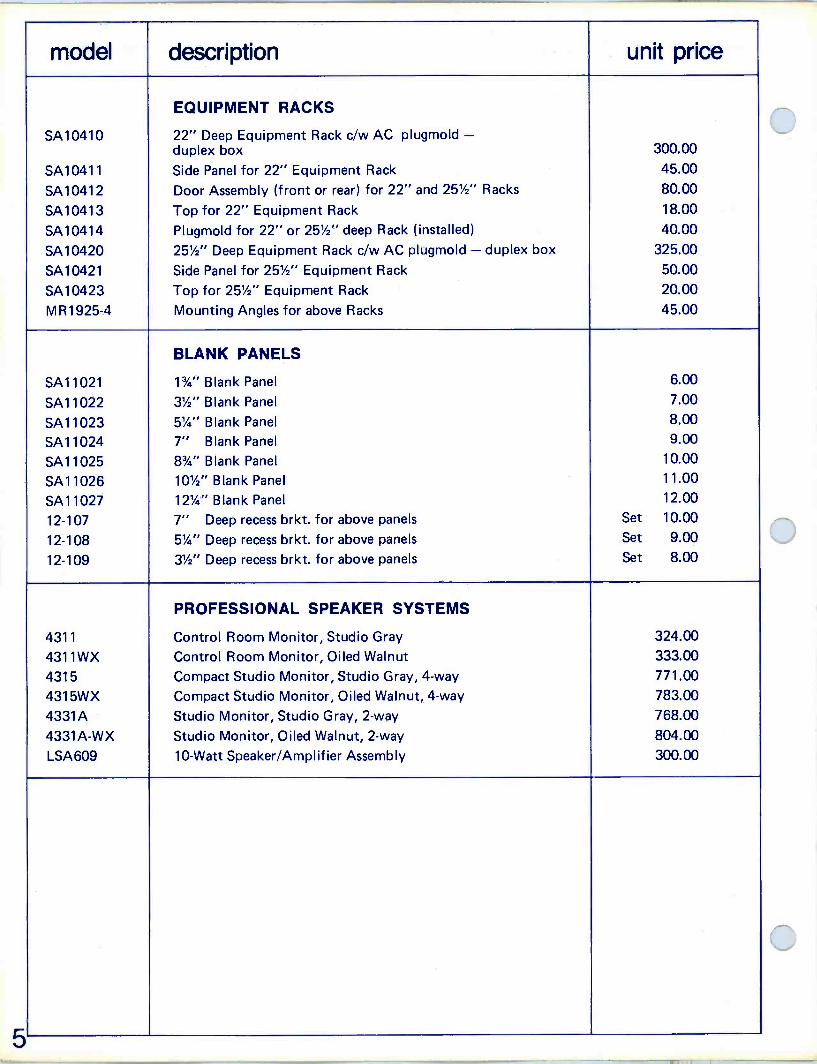
model description unit price
EQUIPMENT RACKS
SA10410 22" Deep Equipment Rack c/w AC plugmold - duplex box 300.00
SA10411 Side Panel for 22" Equipment Rack 45.00
SA10412 Door Assembly (front or rear) for 22" and 25'/2" Racks 80.00
SA10413 Top for 22" Equipment Rack 18.00
SA10414 Plugmold for 22" or 25'/2" deep Rack (installed) 40.00
SA10420 25'/2" Deep Equipment Rack c/w AC plugmold - duplex box 325.00
SA10421 Side Panel for 25'/2" Equipment Rack 50.00
SA10423 Top for 251/2" Equipment Rack 20.00
MR1925-4 Mounting Angles for above Racks 45.00
BLANK PANELS
SA11021 13/4" Blank Panel 6.00
SA11022 3'/2" Blank Panel 7.00
SA11023 5'/4" Blank Panel 8.00
SA11024 7" Blank Panel 9.00
SA11025 83/4" Blank Panel 10.00
SA11026 10'/2" Blank Panel 11.00
SA11027 121/4" Blank Panel 12.00
12-107 7" Deep recess brkt. for above panels Set 10.00
12-108 5'/4" Deep recess brkt. for above panels Set 9.00
12-109 3'/2" Deep recess brkt. for above panels Set 8.00
PROFESSIONAL SPEAKER SYSTEMS
4311 Control Room Monitor, Studio Gray 324.00
4311WX Control Room Monitor, Oiled Walnut 333.00
4315 Compact Studio Monitor, Studio Gray, 4 -way 771.00
4315WX Compact Studio Monitor, Oiled Walnut, 4 -way 783.00
4331A Studio Monitor, Studio Gray, 2 -way 768.00
4331A-WX Studio Monitor, Oiled Walnut, 2 -way 804.00
LSA609 10 -Watt Speaker/Amplifier Assembly 300.00

model description unit price
MISCELLANEOUS
111 B Orban/Parasound Dual Channel Reverb Chamber 695.00
SA137A Counter, basic chassis only 500.00
SA137A-01 Display Panel c/w 7 ft. cable (vu size) 300.00
SA137A-02 Display Panel C/W 7 Ft. Cable (Spkr. Size) 300.00
SA137A-07 Counter Control Panel (desk mounting) 200.00
SA137A-06 Counter Control Panel (console mounting) 200.00
SA138A Clock Main Chassis 500.00
SA138A-2 Display Panel for Clock Main Chassis 300.00
SA138A-01 Display Panel c/w 7 ft. cable (vu size) 300.00
SA138A-02 Display Panel c/w 7 ft. cable (spkr. size) 300.00
SA141 Tape Input Swr. with line output and Cue speaker 545.00
EQ155 Variable Equaliser 400.00
OT157 Variable Oscillator 350.00
CP159 Compressor/Limiter 550.00
4930 Can of MR I -Blue Touch-up Paint 6.00
SA14021 Extended Range Audio Level Meter 575.00
408-2 L.D.R. Tube for AM408 40.00
EM7800-1 Extender Module for 77 & 7800 Consoles 50.00
3002 MRI Matching Transformer 600/600, 150/150 40.00
842 Hammond Bridging Transformer (20K) 40.00
ARISTOCART Alignment Tape 35.00
MRI-1007 1500 MFD, 75V Capacitor 5.00
5522 Schadow 30 Volt, 40 mA. Lamp 1.50
MRI-502-M P & G Mono Attendator 175.00
MR I -502-S P & G Stereo Attendator 250.00
SA139 Voice Operated Relay 100.00
PJ660-5 ADC Xmas Tree Terminal Block 15.00
6

McCURDY RADIO INDUSTRIES INC.
HEAD OFFICE: 1711 CARMEN DRIVE, ELK GROVE VILLAGE, CHICAGO, ILL. 60007 PHONE: (312) 640-7077
EASTERN OFFICES: 1051 CLINTON ST., BUFFALO, N.Y. 14206 PHONE: (716) 854-6700 TWX: (610) 492-1373
223 W. SADDLE RIVER ROAD, SADDLE RIVER, N.J. 07458 PHONE: (201) 327-0750 TWX: (710) 988-2254
State and Local Taxes excluded.
Prices shown F.O.B. Plant
Shipping by Surface Freight unless otherwise specified.
Prices Subject to Change without notice.

PRICE LIST Effective November,1ST
1974
State and Local Taxes excluded.
Prices shown F.O.B. Buffalo, N.Y.
Shipping by Surface Freight unless otherwise specified.
Prices Subject To Change Without Notice.
McCurdy Radio Industries Inc. 1051 CLINTON STREET, BUFFALO, N.Y. 14206 (716) 854-6700


model description unit price
TURNTABLES AND DISC REPRODUCERS
SP10D Technics Direct Drive Turntables with servo speed control system; 331/3, 45 RPM
Price on request
CH12A 12" Transcription Turntable; 3 -speed (Rim -drive) $ 380.00
CH14 12" Transcription Turntable; 331/3, 45; (Belt Drive) 440.00
SS3157 Monaural Disc Reproducer, with cabinet & Electronics with CH12A Turntable (Less End Bells) 1,500.00
SS3158 Stereo Disc Reproducer, with cabinet and Electronics & CH14 Turntable (Less End Bells) 1,835.00
SS3159 Stereo Disc Reproducer, with cabinet, electronics and SP10D turntable (Less End Bells) 1,940.00
TURNTABLE ACCESSORIES
IW-CH12 Idler Wheel for CHI2A 14.00
DB-CH14 Drive Belt for CHI4 13.00
AT135 Equalized Phono Preamplifier -20 dBm to +8 dBm normal output (selectable) 185.00
SA136-P1 Consists of Housing with Power Supply and one AT135 Equalized Phono Preamplifier; output level -20 dBm to +8 dBm nominal (selectable) 295.00
SA136-P2 Consists of Housing with Power Supply and two AT135 Equalized Phono Preamplifier; output level -20 dBm to +8 dBm nominal (selectable) 480.00
AM275 3 Watt Cue Amplifier for SS3157, SS3158, and SS3159 turntable assemblies 140.00
TM40-12FR 12" Felt/Rubber Mat for CH12A and CH14 15.00
SA10048 End Bell (2 req'd) for Disc Reproducers 28.00
SA10545 45 RPM Adapter for CH12A and CH14 1.50
CARTRIDGES BY STANTON
CALIBRATION STANDARD (with "Longhair" Brush)
Cartridge Color Stylus Model Tracking Force 681 EEE Silver D6800EEE 3/4 to 11/2 Grams 44.00
681 EE Silver D6800EE 3/4 to 11/2 Grams 39.00
681SE Silver D6800SE 2 to 4 Grams 37.00
681A Silver D6807A 11/2 to 3 Grams 37.00
681AMC Silver D6872AMC 3 to 7 Grams 37.00
BROADCAST STANDARD
500EE Gold D5100EE 1 to 2 Grams 22.00
500E Gold D5100E 2 to 5 Grams 20.00
500AA Gold D5105AA 1 to 21/2 Grams 20.00
500A Gold D5107A 2 to 5 Grams 17.00
500AL Gold D5107AL 3 to 7 Grams 17.00
BROADCAST STANDARD - H. P.
600EE Gold D6003EE 1 to 2 Grams 32.00
600E Gold D6004E 11/2 to 3 Grams 29.00
600A Gold D6071A 2 to 4 Grams 26.00
1
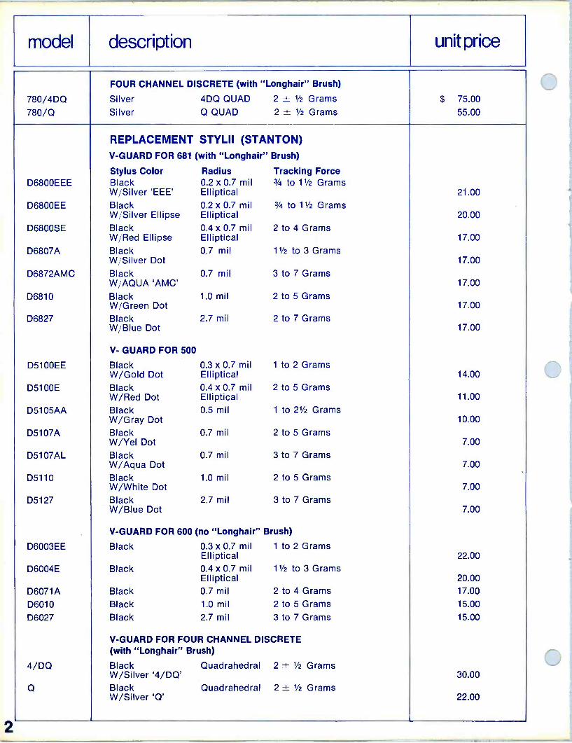
2
model description unit price
FOUR CHANNEL DISCRETE (with "Longhair" Brush)
780/4DQ Silver 4DQ QUAD 2 ± 1/2 Grams $ 75.00
780/Q Silver Q QUAD 2 t 1/2 Grams 55.00
REPLACEMENT STYLII (STANTON) V -GUARD FOR 681 (with "Longhair" Brush)
Stylus Color Radius Tracking Force D6800EEE Black 0.2 x 0.7 mil 3/4 to 11/2 Grams
W Silver 'EEE' Elliptical 21.00
D6800EE Black 0.2 x 0.7 mil 3/4 to 11/2 Grams W Silver Ellipse Elliptical 20.00
D6800SE Black 0.4 x 0.7 mil 2 to 4 Grams W Red Ellipse Elliptical 17.00
D6807A Black 0.7 mil 11/2 to 3 Grams W'Silver Dot 17.00
D6872AMC Black 0.7 mil 3 to 7 Grams W'AQUA 'AMC' 17.00
D6810 Black 1.0 mil 2 to 5 Grams W /Green Dot 17.00
D6827 Black 2.7 mil 2 to 7 Grams W'Blue Dot 17.00
V- GUARD FOR 500
D5100EE Black 0.3 x 0.7 mil 1 to 2 Grams W/Gold Dot Elliptical 14.00
D5100E Black 0.4 x 0.7 mil 2 to 5 Grams W/Red Dot Elliptical 11.00
D5105AA Black 0.5 mil 1 to 21/2 Grams W/Gray Dot 10.00
D5107A Black 0.7 mil 2 to 5 Grams W/Yel Dot 7.00
D5107AL Black 0.7 mil 3 to 7 Grams W/Aqua Dot 7.00
D5110 Black 1.0 mil 2 to 5 Grams W/White Dot 7.00
D5127 Black 2.7 mil 3 to 7 Grams W/Blue Dot 7.00
V -GUARD FOR 600 (no "Longhair" Brush)
D6003EE Black 0.3 x 0.7 mil 1 to 2 Grams Elliptical 22.00
D6004E Black 0.4 x 0.7 mil 11/2 to 3 Grams Elliptical 20.00
D6071A Black 0.7 mil 2 to 4 Grams 17.00
D6010 Black 1.0 mil 2 to 5 Grams 15.00
D6027 Black 2.7 mil 3 to 7 Grams 15.00
V -GUARD FOR FOUR CHANNEL DISCRETE (with "Longhair" Brush)
4/DQ Black Quadrahedral 2 ± 1/2 Grams W/Silver '4/DQ' 30.00
Q Black Quadrahedral 2 ± 1/2 Grams W/Silver 'Q' 22.00
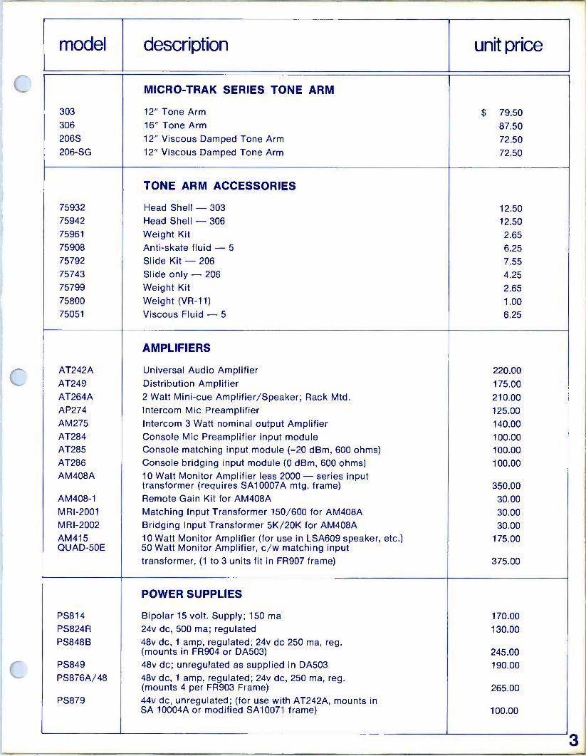
model description unit price
MICRO-TRAK SERIES TONE ARM
303 12" Tone Arm $ 79.50 306 16" Tone Arm 87.50 206S 12" Viscous Damped Tone Arm 72.50 206 -SG 12" Viscous Damped Tone Arm 72.50
TONE ARM ACCESSORIES
75932 Head Shell - 303 12.50 75942 Head Shell - 306 12.50 75961 Weight Kit 2.65 75908 Anti -skate fluid - 5 6.25 75792 Slide Kit - 206 7.55
75743 Slide only - 206 4.25 75799 Weight Kit 2.65 75800 Weight (VR -11) 1.00 75051 Viscous Fluid -5 6.25
AMPLIFIERS
AT242A Universal Audio Amplifier 220.00 AT249 Distribution Amplifier 175.00
AT264A 2 Watt Mini -cue Amplifier/Speaker; Rack Mtd. 210.00 AP274 Intercom Mic Preamplifier 125.00 AM275 Intercom 3 Watt nominal output Amplifier 140.00 AT284 Console Mic Preamplifier input module 100.00 AT285 Console matching input module (-20 dBm, 600 ohms) 100.00 AT286 Console bridging input module (0 dBm, 600 ohms) 100.00 AM408A 10 Watt Monitor Amplifier less 2000 - series input
transformer (requires SA10007A mtg. frame) 350.00 AM408-1 Remote Gain Kit for AM408A 30.00 MRI-2001 Matching Input Transformer 150/600 for AM408A 30.00 MRI-2002 Bridging Input Transformer 5K/20K for AM408A 30.00 AM415 10 Watt Monitor Amplifier (for use in LSA609 speaker, etc.) 175.00 QUAD -50E 50 Watt Monitor Amplifier, c/w matching input
transformer, (1 to 3 units fit in FR907 frame) 375.00
POWER SUPPLIES
PS814 Bipolar 15 volt. Supply; 150 ma 170.00
PS824R 24v dc, 500 ma; regulated 130.00 PS848B 48v dc, 1 amp, regulated; 24v dc 250 ma, reg.
(mounts in FR904 or DA503) 245.00 PS849 48v dc; unregulated as supplied in DA503 190.00 PS876A/48 48v dc, 1 amp, regulated; 24v dc, 250 ma, reg.
(mounts 4 per FR903 Frame) 265.00 PS879 44v dc, unregulated; (for use with AT242A, mounts in
SA 10004A or modified SA10071 frame) 100.00

model description unit price
AUDIO SWITCHERS
CUSTOM CONFIGURATIONS AVAILABLE ON REQUEST
CS9100
CS9200
INTERCOM SYSTEMS
10 x 10 Balanced Intercom System c/w all input amplifiers, all output amplifiers, crosspoints & power supply. One Frame 51/4"
20 x 20 Balanced Intercom Systems c/w all input amplifiers, all output amplifiers, crosspoints & power supplies. 3 Frames 153/4"
Price on request
Price on request
DA501-D1
DA501-D2
DA501-D3
DA501-D4
DA502-D5
DA502-D6
DA503
AUDIO DISTRIBUTION SYSTEMS
Distribution Assembly: one amplifier, one power supply, four outputs Distribution Assembly: one amplifier, one power supply, eight outputs Distribution Assembly: two amplifiers, two power supplies, four outputs, each amplifier Distribution Assembly: two amplifiers, two power supplies, eight outputs, each amplifier Distribution Assembly: six amplifiers, no power supplies, four outputs, each amplifier Distribution Assembly: six amplifiers, no power supplies, eight outputs, each amplifier Audio Distribution Assembly: 6 amplifiers, 36 outputs, power supply, mounted and wired in FR904 frame
$ 500.00
525.00
780.00
800.00
1,690.00
1,780.00
1,295.00
SS4312
SS4386A
SS4388A
SS7400
SS7500
SS7600
AUDIO CONSOLES
12 -Mixer, Dual Channel Monophonic Audio Console, 32 switchable inputs, rotary attenuators, complete cue system, with amplifier and speaker (desk mounting) 6 -Mixer 1 -Channel Audio Console with slide attenuators; each mixer accepts HL and LL inputs, push-button cue system with amplifier and speaker (desk mounting) 8 -Mixer, 1 -Channel Audio Console, each mixer input to accept HL and LL inputs; push-button cue system with amplifier and speaker; provision for DC remote control and additional auxiliary inputs (desk mounting) Mono 2 -Channel Audio Console with slide attenuators. May incorporate up to 12 mixers two inputs per channel. Options include additional input switching, Echo Send, equalizer or compressor inserts and foldback capability. Standard monitor feed and cue system included. (Desk mounting) Stereo Audio Console with slide attenuators. May incorporate up to 10 mixers, 2 inputs per mixer; options include additional input switching, equalizer inserts, compressor limiters, and mono sum channel. Standard monitor feed and cue system included. (Desk mounting) Custom Audio Console, can accommodate up to 20 mono, or 18 stereo mixer channels with audition and program outputs. Options include additional input switching, equalizer inserts and compressor limiters. Standard monitor feed and cue system included. (Desk mounting)
6,850.00
3,800.00
3,500.00
Price on request
Price on request
Price on request

model description unit price
SS7700 Recording and TV Production Console, up to 24 -Mixer Channels with various multiple sub and master channel combinations possible. Each mixer with input sensitivity switching, Echo Send, foldback, cue, solo, and channel - on switch. Space available for individual channel equalizers, master compressors, and multiple foldback outputs. Jackfields may be fitted as required. Price on request
SS7800 Recording and TV Production Console, up to 36 -Mixer Channels with various multiple sub and master channel combinations possible. Each Mixer with input sensitivity switching, Echo send, foldback, cue, solo, and channel - on switch. Space available for individual channel equalizers, master compressors, and multiple foldback outputs. Jackfields may be fitted as required Price on request
ACCESSORIES FOR DESK -MOUNTING CONSOLES
RC700 Dual Pedestal Console Mounting Desk with white arborite top and recessed remote control panel $ 900.00
SS7408 Turntable remote 'START' pushbutton for console desk c/w panel 30.00
SS7409 Reel Tape Remote 'START-STOP' pushbuttons for console desk c/w panel 60.00
SS7410 Cartridge Tape Remote 'START' pushbuttons for console desk c/w panel 30.00
SS4361 B Monaural Announce Turret c/w microphone preamplifier (less cable) and talkback switch 500.00
SS4371B Dual Channel Announce Turret c/w microphone preamplifier; left -center -right switch and talkback switch (less cable) 600.00
AMPLIFIER FRAMES
FR903 Mounting Frame (less connectors) for PS876A/48 31/2 Rack Space 85.00
FR950-1 Frame Receptable Kit for above 5.00
FR904 Universal Card Frame (less connectors) 31/2" Rack Space 85.00
FR904-1 Frame Receptacle Kit (15 -pin) 5.00
FR904-2 Frame Receptacle Kit (30 -pin) 5.00
FR904-3 Frame Receptacle Kit (16 -pin) for PS848B, PS849, (including connector cover) 15.00
FR905 Mounting Frame (Extrusion Modules) 51/4" Rack Space 100.00
FR906 Mounting Frame (Universal Card Frame) 51/4" Rack Space 100.00
EM14 Extender Module for FR904 Frame 50.00
FR907 Mounting Frame for up to 3 QUAD 50E Amplifiers 95.00
SA10007A Mounting Frame for up to 4 AM408A Amplifiers complete with connectors 175.00
SA10004A Mounting Frame for up to 6 AT242A Amplifiers 150.00
SA10071 Mounting Frame for 1 AT242A 30.00
SA10071 (M) Mounting Frame for 1 PS879 30.00
SA10072 Mounting Frame for 1 Module (AT135, etc.) 30.00

model description unit price
JACKFIELDS AND PATCH CORDS
SA10100 Prewired Jackfield; unshielded (Positions 1, 2, 3, 4) $ 150.00
SA10100-S Prewired Jackfield; shielded (Positions 1, 2, 3, 4) 200.00
SA10102 Unwired Jackfield 100.00
SA10131 1 ft. Patch Cord 8.00
SA10132 2 ft. Patch Cord 8.50
SA10133 3 ft. Patch Cord 9.00
SA10134 4 ft. Patch Cord 10.00
SA10136 6 ft. Patch Cord 11.00
MODULAR ENCLOSURES
SA10040 Pedestal 150.00
SA10041 Tape Machine Adapter Frame 90.00
SA10043 Cartridge -Tape Machine Housing (desk mounting) 200.00
SA10044 Cartridge -Tape Machine Housing, (floor mtg.) c/w Rear door 250.00
SA10045 Turntable Mounting Board 55.00
SA10045-1 Turntable Arm Guard 10.00
SA10046 Blank Top Board 50.00
SA10047 Removable Door 35.00
SA10048 End Bell 25.00
EQUIPMENT RACKS
SA10410 22" Equipment Rack 250.00
SA10411 Side Panel 30.00
SA10412 Door Assembly (Front or Rear) 50.00
SA10413 Rack Top 15.00
SA10414 Plug Mold for 22" or 251/2" Rack. Installed 30.00
SA10420 251/2" Equipment Rack 275.00
SA10421 Side Panel 33.00
SA10412 Door Assembly (Front or Rear) 50.00
SA10423 Rack Top 15.00
12-24 x 3/4 Machine Screws (As supplied with Racks) .05
12-24 Speed Nuts (As supplied with Racks) .05
BLANK PANELS
SA11021 13/4" Blank Panel 5.00
SA11022 31/2" Blank Panel 5.25
SA11023 51/4" Blank Panel 5.50
SA11024 7" Blank Panel 5.75
SA11025 83/4" Blank Panel 6.00
SA11026 101/2" Blank Panel 7.50
SA11027 121/4" Blank Panel 8.50

model description unit price
MISCELLANEOUS
106C Orban/Parasound Spring Reverb $ 695.00
EQ155A Variable Equalizer 395.00
CP159 Compressor/Limiter 395.00
OT157 Variable Oscillator 395.00
LSA609 10 Watt Speaker/Amplifier mounted in a walnut -finished cabinet with 15° reverse slope for wall mounting 295.00
LS609 As above, less AM415 Amplifier 150.00
4930 Can of Touch-up Paint (MRI-Blue) 3.50
SA14021A Extended Range Audio Level Meter 435.00
5728 Stanton Dynaphase Twenty-eight Headphone 21.00
5740 Stanton Dynaphase Forty Headphone 36.00
5765 Stanton Dynaphase Sixty-five Four 'C' (Four Channel) Headphone 48.00
5760 Stanton Dynaphase Sixty Headphone 50.00
5751 Stanton Dynaphase Fifty Headphone 42.00
5741 Stanton Dynaphase Control Box 15.00
ITC CARTRIDGE RECORDER/REPRODUCER
RP -0001 Monophonic with 1 kHz primary cue 1,250.00
RP -0002 Stereophonic with 1 kHz primary cue 1,495.00
RP -0003 Monophonic with 1 kHz primary, 150 Hz secondary, and 8 kHz tertiary cues 1,325.00
RP -0004 Stereophonic with 1 kHz primary, 150 Hz secondary, and 8 kHz tertiary cues 1,570.00
RP -0005 Monophonic, Hi -Speed Cue with 1 kHz 150 Hz, and 8 kHz cues 1,415.00
RP -0006 Stereophonic, Hi -Speed Cue with 1 kHz 150 Hz and 8 kHz cues 1,660.00
RP series recorder/reproducers accept the NAB 'A', 'B' and 'C' size cartridges
ITC CARTRIDGE REPRODUCER
SP -0001 Monophonic with 1 kHz primary cue 695.00
SP -0002 Stereophonic with 1 kHz primary cue 795.00
SP -0003 Monophonic with 1 kHz primary, 150 Hz secondary, and 8 kHz tertiary cues 745.00
SP -0004 Stereophonic with 1 kHz primary, 150 Hz secondary, and 8 kHz tertiary cues 845.00
SP -0005 Monophonic, Hi -Speed Cue with 1 kHz, 150 Hz, and 8 kHz cues 825.00
SP -0006 Stereophonic, Hi -Speed Cue with 1 kHz, 150 Hz, and 8 kHz cues 925.00
SP series reproducers accept the NAB 'A' and 'B' size cartridges
7

model description unit price
3D-0001
3D-0002
3D-0003
3D-0004
ITC CARTRIDGE THREE -DECK REPRODUCER
Monophonic with 1 kHz primary cue
Stereophonic with 1 kHz primary cue Monophonic with 1 kHz primary, 150 Hz secondary, and 8 kHz tertiary cues
Stereophonic with 1 kHz primary, 150 Hz secondary, and 8 kHz tertiary cues
$1,595.00
1,895.00
1,745.00
2,045.00
ACCESSORIES
AS -0001 Audio Switcher, three input single output balanced audio switching, 0-dBm Insertion loss. Two required for stereophonic applications. 95.00
RACK MOUNTING FRAMES
SA -10044-2 Rack Mounting Frame for RP series machine or 2 -SP series machines 35.00
SA -10044-4 Blank Panel to cover area when only 1 -SP machine is housed in the SA10044-2 8.00
SA -10044-1 Rack Mounting Frame for 2-3D series machines 50.00
SA -10044-3 Blank Panel to cover area when only 1-3D machine is housed in the SA -10044-1 10.00
SA -10044-8 Blank Panel to cover area above WRA series machine when mounted in SA -10044-2 beside the 3D machine 8.00
NOTE 1 All Equipment for table -top mounting and 60 Hz 117 VAC operation
NOTE 2 All 3 -Tone RP - SP series may be ordered with 71-30 IPS motors and circuitry to provide for 30 IPS operation upon sensing 150 Hz end of message signal.
WRA RECORD AMPLIFIER
WRA-0001 Monophonic with 1 kHz primary cue 560.00
WRA-0002 Stereophonic with 1 kHz primary cue 705.00
WRA-0003 Monophonic with 1 kHz primary, 150 Hz secondary, and 8 kHz tertiary cues 585.00
WRA-0004 Stereophonic with 1 kHz primary, 150 Hz secondary, and 8 kHz tertiary cues 730.00
8


Price State and Local Taxes Excluded
Price Shown F.O.B. Point of Manufacture
Prices Subject to Change Without Notice
Effective May, 1970
MCCURDY RADIO INDUSTRIES LIMITED (416) 751-6262 108 CARNFORTH ROAD O TORONTO 16 O CANADA j TELEX 02-21550
Li .
hcCl:.".DY RADIO INDUSTRIES INCORPORATED 854-0/ 00 1051 CLINTON STREET . O BUFFALO fh. N.Y. 14200
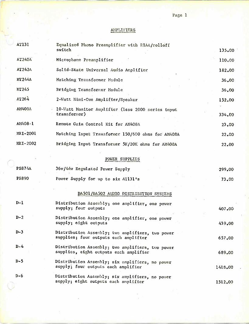
Page 1
AMPLIFIERS
AT131 Equalized Phono Preamplifier with RIAA/rollóff switch
AT240A Microphone Preamplifier
AT242A Solid -State Universal Audio Amplifier
MT244A Matching Transformer Module
MT245 Bridging Transformer Module
AT264 2 -Watt Mini -Cue Amplifier/Speaker
AM408A 10 -Watt Monitor Amplifier (less 2000 series input transformer)
AM408-1 Remote Gain Control Kit for AM408A
MRI-2001 Matching Input Transformer 150/600 ohms for AM408A
MRI-2002 Bridging Input Transformer 5K/20K ohms for AM408A
POWER SUPPLIES
PS874A 36v/44v Regulated Power Supply
PS890 Power Supply for up to six AT131's
D-1
D-2
supply; eight outputs
D-3 Distribution Assembly; two amplifiers, two power supplies; four outputs each amplifier
D-4 Distribution Assembly; two amplifiers, two power supplies, eight outputs each amplifier
D-5 Distribution Assembly; six amplifiers, no power supply; four outputs each amplifier
DA501JDA502 AUDIO DISTRIBUTION SYSTEMS
Distribution Assembly; one amplifier, one power supply; four outputs
Distribution Assembly; one amplifier, one power
D-6 Distribution Assembly; six amplifiers, no power supply; eight outputs each amplifier
135.00
110.00
182.00
36.00
36.00
152.00
334.00
23.00
22.00
22.00
299.00
73.00
407.00
439.00
657.00
689.00
1418.00 .
1512.00

Page 2
IABIE TOP MODELS
SS4360
SS436LB
SS4360-1
AT263
AUDIO CONSOLES
Basic 34 Input, 10 Mixer, Dual Channel (MO;AURAL) Console (LESS all input modules)
Monaural Announce Control Turret ch microphone preamplifier (less cable)
Dual Pedestal Mounting Desk with recessed control panel, wiring tray and removable script board
Extra 10 Watt Monitor Channel Kit for SS4360 ONLY
SS4370 Basic 28 Input, 8 Mixer, Dual Channel STEREO Console (LESS all input modules)
SS437133 Stereo Announce Control Turret C/u microphone preamplifier and left -center -right switch (less cable)
Plug -In Input Modules for SS4360 and SS4370:
AT240A Microphone Preamplifier 37.5/150 ohms
MT244A Matching Input Transformer 150/600 ohms
MT245 Bridging Input Transfo ri= 5K/20K ohms
SS4386 Six Mixer Single Channel Audio Console, each mixer to accept HL and LL inputs; complete with pushbutton cue system. Equipped with slide attenuators.
SS4388 Eight Mixer Single Channel Audio Console, each mixer to accept HL and LL inputs; complete with pushbutton cue system. Equipped with rotary attenuators.
SS4395 Six Mixer, Slide Attenuator, Dual Channel Audio Console. Complete with 6 microphone preamplifiers, cue amplifier and power. supply, less monitor amplifier.
SS4396 Twelve Mixer, Slide Attenuator, Dual Channel Audio Console. Complete with 12 microphone preamplifiers, cue amplifiers and poser supply, less monitor amplifier.
4809.00
473.00
761.00
181,00
6017.00
557.00
110.00
36.00
36.00
3255.00
2835.00
4825.00
7600.00

Page 3
SS 4900
SS5200
AUDIO CONSOLES (cont'd)
Audio Production, TV and Recording Cónsole, up to 30 mixer channels 4 to 8 subs, 2 to 4 program channels. Space for all other accessories used with a console of this type.
Audio Production Console, up to 20 mixer channels, 4 subs, 2 to 4 program channels, echo send, prelisten cue and monitoring facilities. Space for input sensitivity switches, equalizers and compressors as required.
PRICE ON REQUEST
PRICE ON REQUEST
AUDIO SWITCHING j.QUIPMENT .
Reed Relay 13.00
Armature Relay 9.00
SM8/SM18 Modules 32.00
Isolation Pads - 8 pads per card installed 2.00
Mixing Pads - 8 pads per card installed 2.00
Transistor hold -cancel circuit - installed 21.00
OPTIONS:
FR904 Equipment Frame 79.00
FR904-2 Frame Receptacle Kit - Elco edge connector 4.00
Power Supply - 24v U.C.
Power Supply Mounting Frame
ACCESSORIES
AMPLIFIER FRAMES
FR -903 Mounting Frame (less connectors) for universal plug-in modules 79.00
FR -904 Universal Card Frame (less connectors) 79.00
FR -904-1 Receptacle Kit for intercom etc. 2.50
FR -904-2 Receptacle Kit for audio switcher 4.00

Page 4
AMPLIFIER FRAMES (cont'd)
SA10004A
SA10007A
SA10007-2
ACCESSORIES (conted)
Mounting Frame for 240 series modules
Amplifier/Power Supply Mounting Frame
4k" Wide Blank Frame Insert for SA10007A frame (same size as PS874A or AU408A)
EQUIPMENT RACKS
SA10410 22" Equipment Rack
SA10411 Side Panel
SA10412 Door Assembly (front or rear)
SA10413 Rack Top
SA10420 252" Equipment Rack
SA10421 Side Panel
SA10412 Door Assembly (front or rear)
SA10423 Rack Top
110.00
121.00
8.00
210.00
28.00
47.00
16.00
221.00
32.00
47.00
16.00
BLANK PANELS
SA11021 1-3/4" Blank Panel 5.00
SA11022 3-1/2" Blank Panel 6.00
SA11O23 5-1/4" Blank Panel 6.00
SA11024 7" Blank Panel 6.00
SA11025 8-3/4" Blank Panel 6.00
SA11026 10-1/2" Blank Panel 7.00
JACKFIEI DS
SA10100 Prewired Jackfield, unshielded (positions 1,2,3,4) 131.00
SA10100-S Prewired Jackfield, shielded (positions 1,2,3,4) 189.00
SA10102 Unwired Jackfield 74.00
SA10131 1 ft. Patch Cord 7.00

Page 5
JACKFIELDS (cont'd)
SA10132 2 ft. Patch Cord 8.00
SA10133 3 ft. Patch Cord 8.50
SA10136 6 ft. Patch Cord 9.00
VU METERS
SA14021A Extended Range Audio Level Meter 415.00
MODULAR ENCLOSURES
SA10040 Pedestal 131.00
SA10041 Tape Machine Adapter Frame 89.00
SA10042 Cartridge Tape Housing c/w rear door 221.00
SA10045 Turntable Mounting Board 60.00
SA10045-1 Turntable Arm Guard 9.00
SA10046 Blank Top Board 37.00
SA10047 Removable Door 30.00
SA10048 End Bell 18.00
SPEAKER/AMPLIFIERS
LSA608 10 -Watt Speaker/Amplifier mounted in walnut finished rectangular cabinet.
LSA609 10 -Watt SpeakergAmplifier mounted in walnut finished cabinet with 15 reverse slope for wall mounting.
PORTABLE EQUIPMENT
PE2400 Four -Mixer Single -Channel Portable Console, complete with AC power supply. Each mixer to accept HL and LL inputs. Also available in rack mount.
231.00
231.00
1360.00

Pag' 6
CS7000 SERIES INTERCOM SYSTEM
51.111 Crosspol rtt 10.00
SMX-12 Matrix Card A 13.00
S1 -12 Matrix Card B, less frame etc. 9.00
Resistor. .16
Resistor - installed .32
AP -272 Input Amplifier 95.00
AM -273 Output Amplifier 142.00
CM -272-1 AGC Card "34.00
Output Frame 131.00
Input Frame 189.00
Matrix Frame 189.00
CS -7010 10 x 10 Basic not including rack 1649.00
CS -7020 18 x 2.0 Basic not including rack 2838.00
CS -7040 36 x 40 Basic not including rack ON REQUEST
LS7104
CP7101
Power Supply Depends on size of system
Speaker Unit c/w volulae control
Key Panel - 5 keys
Microphone Kit
40.00
95000
ON REQUEST

AMFMTV BROADCAST EQUIPMENT
McCurdy Radio Industries,
Inc. 57 North Putnam Street Danvers, Massachusetts 01923
(617) 744-6411