an active ferrofluid display - the menlo roundtable
TRANSCRIPT
An Active Ferrofluid Display
Kevin Taylor
1 The Big Idea
The goal of my project is to create a moving, flowing exhibit of ferrofluid. There will be a shallow basin filled with the fluid and several iron mini-sculptures protruding through the liquid. On the underside, each of those iron shapes will have wire coils wrapped around it, so that the entire hunk of iron will behave like an electromagnet. By varying the power of the electromagnets, I hope to create a visually inspiring piece that will be a wonderful way to interest people in science.
My inspiration came from my previous explorations of non-Newtonian fluids (of which magnetic fluids form one category) and also from videos I have viewed on the Internet that showed truly stunning behaviors of ferrofluid. In particular, the works of Sachiko Kodama [1] and Martin Frey [2] stimulated my interest in ferrofluid.
There will be several new frontiers for me in this project. I have much to explore in the field of fluid dynamics before I have a complete grasp of the behaviors of ferrofluid. Additionally, there are several options for the control mechanism for the electromagnets, and all of them require me to delve more deeply into the world of electronics and perhaps microcontrollers as well. My goal for the control scheme is to design ways to run automated routines as well as an interactive element that would allow the audience to manipulate the electromagnets by plugging in their own music player or moving the electromagnets themselves. An audio input option will suffice for both of these applications. This would also be able to process actual music files into a coherent ferrofluid show. Anyone could plug in their iPod and see their favorite song playing in ferrofluid. No large computer unit would be necessary to control the electromagnets, as any music player would do.
This paper was written for Dr. James Dann’s Applied Science Research class in the spring of 2009.
For the pre-planned routines, I will be using the two audio outputs (left and right speakers) as analog outputs whose amplified signal will control the electromagnets. The sound file can easily be created and modified in Audacity, a free music-editing application. The ferrofluid’s behavior could be changed by altering the frequency or amplitude of the audio signal. If I want slow, gradual changes, I will have to find an amplifier that will not filter out signals that are near-DC, unless I find that amplitude is a better control mechanism than frequency. A diode in the circuit cuts out any negative signal.
2 What is Ferrofluid?
Ferrofluid is a liquid that contains nanoscale iron particles, usually magnetite or a similar magnetizable compound. The magnetic particles are so small (~10 nm) that they can be stably suspended by Brownian motion and will not settle when left undisturbed for indefinite periods of time. I have found this to be true for time periods of at least two weeks. An additive called a surfactant prevents the ferrous particles from clumping together or precipitating out of the fluid. Surfactant is a long hydrocarbon molecule with a charged end that electrostatically attracts the magnetite particles, and a nonpolar end that buffers it from other particles. This prevents magnetite particles from clumping together and becoming too large to suspend, even in the presence of very strong magnetic fields. The electric repulsion forces between molecules will always be greater than any magnetic field I could create. This also ensures that the magnetic properties of the liquid are evenly distributed. The most common surfactant is oleic acid, but there are others, such as soy lecithin, which is an edible surfactant used in food preparation [3].
Ferrofluid is therefore known as a colloidal suspension, a substance with the properties of both a liquid and a solid. Normally, ferrofluid behaves just like a liquid, but magnetic fields reveal the solid structure provided by the ferromagnetic particles. The particles align with the magnetic field, pushing themselves into small peaks that look like magnetic field lines (see Figure 1). I will exploit this effect to create my display.
34 Kevin Taylor
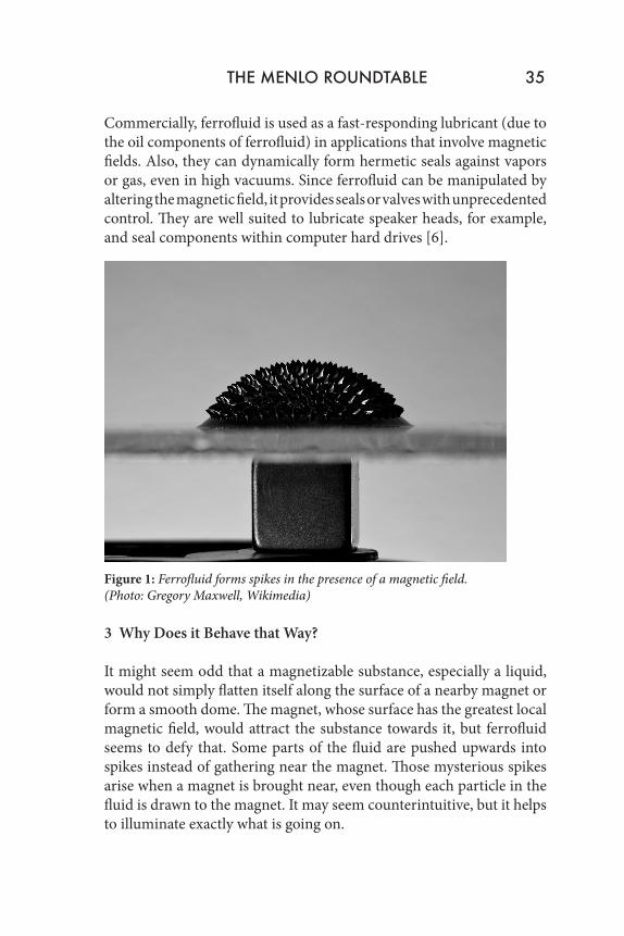
Commercially, ferrofluid is used as a fast-responding lubricant (due to the oil components of ferrofluid) in applications that involve magnetic fields. Also, they can dynamically form hermetic seals against vapors or gas, even in high vacuums. Since ferrofluid can be manipulated by altering the magnetic field, it provides seals or valves with unprecedented control. They are well suited to lubricate speaker heads, for example, and seal components within computer hard drives [6].
Figure 1: Ferrofluid forms spikes in the presence of a magnetic field. (Photo: Gregory Maxwell, Wikimedia)
3 Why Does it Behave that Way?
It might seem odd that a magnetizable substance, especially a liquid, would not simply flatten itself along the surface of a nearby magnet or form a smooth dome. The magnet, whose surface has the greatest local magnetic field, would attract the substance towards it, but ferrofluid seems to defy that. Some parts of the fluid are pushed upwards into spikes instead of gathering near the magnet. Those mysterious spikes arise when a magnet is brought near, even though each particle in the fluid is drawn to the magnet. It may seem counterintuitive, but it helps to illuminate exactly what is going on.
THE MENLO ROUNDTABLE 35
Each particle of magnetite, usually encompassing only a single domain, has two poles, just as every solid magnet does. When a magnet comes near the fluid, one pole of the particle is attracted, and the other is repulsed. The particle then orients itself so that the attracted side is pointing towards the magnet, and now, since that side is closer to the magnetic field source than the opposite pole, the attraction force is stronger than the repulsion force. Thus the fluid will follow the movement of a magnet as you trace it around.
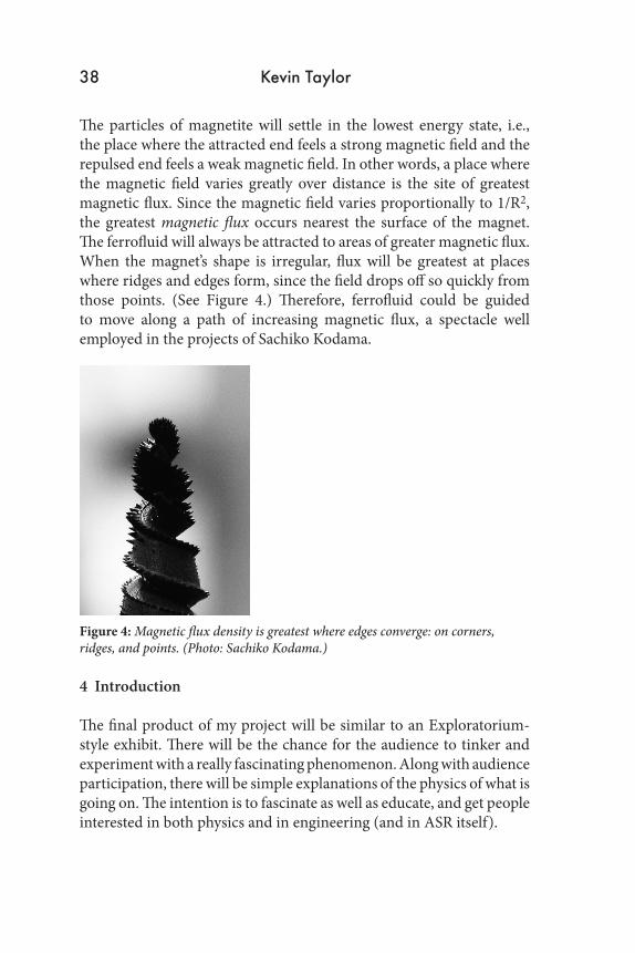
Spikes form because billions of particles of magnetite and their much larger attached surfactants are aligning in the same direction along the same axis; in effect, they are stacking on top of one another. Notice that in places where the magnetic field is not perpendicular to the plane of the fluid, no spikes form because the magnetite is orienting itself horizontally and the fluid spreads out evenly. The origin of the spikes is due to the amplification of microscopic perturbations already present in the fluid [4]. However, the force of the magnetic field in creating these spikes is being resisted by the surface tension of the ferrofluid. As the magnetic field becomes more powerful, surface tension becomes less potent by comparison and a greater number of smaller, shorter spikes form [5]. (See Figures 2 and 3.) This phenomenon is called normal field instability [5]. Overcoming gravitation and surface tension, the magnetic particles arrange themselves in a magnetically ideal formation. This vividly illustrates the proportion of magnetic field lines versus distance from their source, since surface tension remains constant. The number and height of spikes vary greatly in ferrofluids with different surface tensions arising from the use of different surfactant or altered reagent proportions.
36 Kevin Taylor
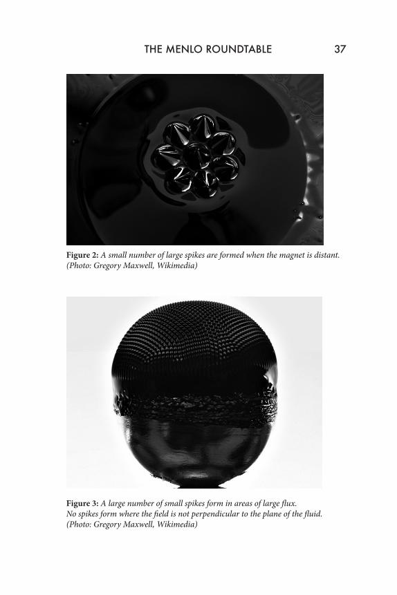
Figure 2: A small number of large spikes are formed when the magnet is distant. (Photo: Gregory Maxwell, Wikimedia)
Figure 3: A large number of small spikes form in areas of large flux. No spikes form where the field is not perpendicular to the plane of the fluid. (Photo: Gregory Maxwell, Wikimedia)
THE MENLO ROUNDTABLE 37
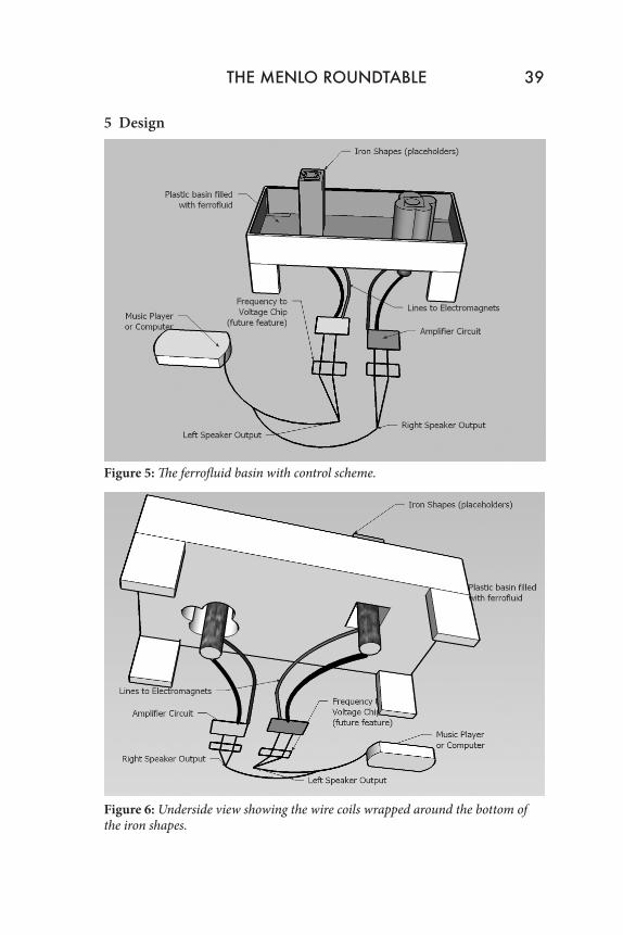
The particles of magnetite will settle in the lowest energy state, i.e., the place where the attracted end feels a strong magnetic field and the repulsed end feels a weak magnetic field. In other words, a place where the magnetic field varies greatly over distance is the site of greatest magnetic flux. Since the magnetic field varies proportionally to 1/R2, the greatest magnetic flux occurs nearest the surface of the magnet. The ferrofluid will always be attracted to areas of greater magnetic flux. When the magnet’s shape is irregular, flux will be greatest at places where ridges and edges form, since the field drops off so quickly from those points. (See Figure 4.) Therefore, ferrofluid could be guided to move along a path of increasing magnetic flux, a spectacle well employed in the projects of Sachiko Kodama.
Figure 4: Magnetic flux density is greatest where edges converge: on corners, ridges, and points. (Photo: Sachiko Kodama.)
4 Introduction
The final product of my project will be similar to an Exploratorium-style exhibit. There will be the chance for the audience to tinker and experiment with a really fascinating phenomenon. Along with audience participation, there will be simple explanations of the physics of what is going on. The intention is to fascinate as well as educate, and get people interested in both physics and in engineering (and in ASR itself).
38 Kevin Taylor
5 Design
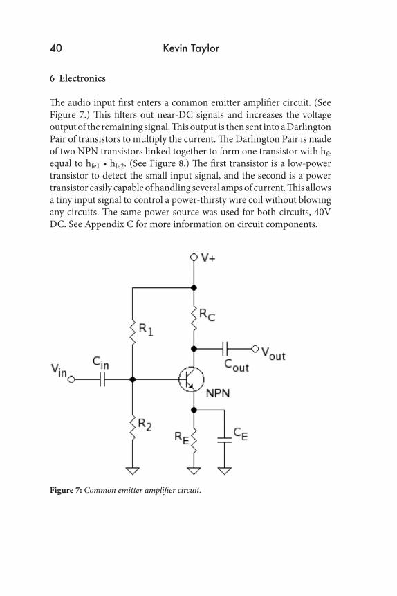
Figure 5: The ferrofluid basin with control scheme.
Figure 6: Underside view showing the wire coils wrapped around the bottom of the iron shapes.
THE MENLO ROUNDTABLE 39
6 Electronics
The audio input first enters a common emitter amplifier circuit. (See Figure 7.) This filters out near-DC signals and increases the voltage output of the remaining signal. This output is then sent into a Darlington Pair of transistors to multiply the current. The Darlington Pair is made of two NPN transistors linked together to form one transistor with hfe equal to hfe1 • hfe2. (See Figure 8.) The first transistor is a low-power transistor to detect the small input signal, and the second is a power transistor easily capable of handling several amps of current. This allows a tiny input signal to control a power-thirsty wire coil without blowing any circuits. The same power source was used for both circuits, 40V DC. See Appendix C for more information on circuit components.
Figure 7: Common emitter amplifier circuit.
40 Kevin Taylor
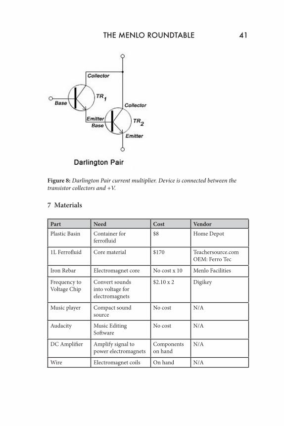
Figure 8: Darlington Pair current multiplier. Device is connected between the transistor collectors and +V.
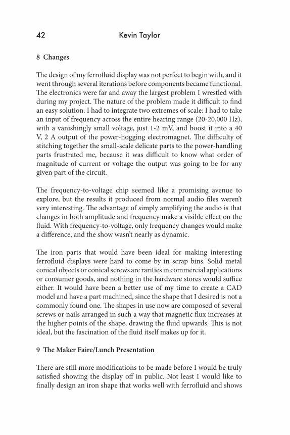
7 Materials
Part Need Cost VendorPlastic Basin Container for
ferrofluid$8 Home Depot
1L Ferrofluid Core material $170 Teachersource.comOEM: Ferro Tec
Iron Rebar Electromagnet core No cost x 10 Menlo Facilities
Frequency to Voltage Chip
Convert sounds into voltage for electromagnets
$2.10 x 2 Digikey
Music player Compact sound source
No cost N/A
Audacity Music Editing Software
No cost N/A
DC Amplifier Amplify signal to power electromagnets
Components on hand
N/A
Wire Electromagnet coils On hand N/A
THE MENLO ROUNDTABLE 41
8 Changes
The design of my ferrofluid display was not perfect to begin with, and it went through several iterations before components became functional. The electronics were far and away the largest problem I wrestled with during my project. The nature of the problem made it difficult to find an easy solution. I had to integrate two extremes of scale: I had to take an input of frequency across the entire hearing range (20-20,000 Hz), with a vanishingly small voltage, just 1-2 mV, and boost it into a 40 V, 2 A output of the power-hogging electromagnet. The difficulty of stitching together the small-scale delicate parts to the power-handling parts frustrated me, because it was difficult to know what order of magnitude of current or voltage the output was going to be for any given part of the circuit.
The frequency-to-voltage chip seemed like a promising avenue to explore, but the results it produced from normal audio files weren’t very interesting. The advantage of simply amplifying the audio is that changes in both amplitude and frequency make a visible effect on the fluid. With frequency-to-voltage, only frequency changes would make a difference, and the show wasn’t nearly as dynamic.
The iron parts that would have been ideal for making interesting ferrofluid displays were hard to come by in scrap bins. Solid metal conical objects or conical screws are rarities in commercial applications or consumer goods, and nothing in the hardware stores would suffice either. It would have been a better use of my time to create a CAD model and have a part machined, since the shape that I desired is not a commonly found one. The shapes in use now are composed of several screws or nails arranged in such a way that magnetic flux increases at the higher points of the shape, drawing the fluid upwards. This is not ideal, but the fascination of the fluid itself makes up for it.
9 The Maker Faire/Lunch Presentation
There are still more modifications to be made before I would be truly satisfied showing the display off in public. Not least I would like to finally design an iron shape that works well with ferrofluid and shows
42 Kevin Taylor

off its climbing abilities. Additionally, I plan to allow the observers another dimension of interactivity: the electromagnets underneath the basin will not be affixed to a single place. They will rest in mobile stands that serve to both stabilize the electromagnet and keep hands off the wires, which can get quite hot if left on for too long. Also, I may toss a bunch of small screws and nails into the basin, hidden beneath the surface of the ferrofluid, that will reveal themselves in the form of unexpected patterns in the fluid when the magnet is passed by. I have thought about providing permanent magnets to the observers, but I think they may mistakenly hold the magnet above the fluid basin, resulting in disaster as ferrofluid stains their hands.
Accompanying the exhibit, I will write a blurb, partially excerpted from the explanation provided here, explaining the science behind the spectacle. I want to exploit the focus of attention to demonstrate that the principles behind the behavior of ferrofluid are just as neat as the spikes themselves.
10 Notes
[1] There is another class of magnetic fluid called a magnetorheological fluid with particles sized 1-10 μm, which solidifies when a magnetic field is applied, instead of remaining liquid, as ferrofluid does. This property gives unique advantages to both fluids, and explains why ferrofluid is often used as a lubricant or ring-sealant.
11 Citations
[1] Kodama, Sachiko. “Protrude, Flow;” “Morphotowers.”http://www.kodama.hc.uec.ac.jp/index-e.html
[2] Frey, Martin. “SnOil -A Physical Display Based on Ferrofluid.” http://www.freymartin.de/en/projects/snoil
[3] Vitori, William S. Experiments in Nanotechnology: Ferrofluids. Carnegie Mellon University, July 2005.
THE MENLO ROUNDTABLE 43
[4] R. Friedrichs, A. Engel. Statics and dynamics of a single ferrofluid-peak. The European Physical Journal B Condensed Matter and Complex Systems, vol. 18, no. 2, pg 329-335. November 2000.
[5] University of Wisconsin Materials Research Science and Engineering Center. “Ferrofluids.” http://mrsec.wisc.edu/Edetc/background/ferrofluid/index.html
[6] Ferro Tec Corporation. “Magnetic Liquid Technology,” “Ferrofluid Seal Technology.” http://www.ferrotec.com/
12 Appendices
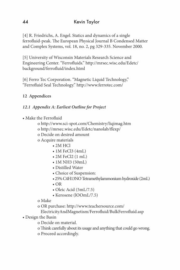
12.1 Appendix A: Earliest Outline for Project
• Make the Ferrofluid o http://www.sci-spot.com/Chemistry/liqimag.htm o http://mrsec.wisc.edu/Edetc/nanolab/ffexp/ o Decide on desired amount o Acquire materials • 2M HCl • 1M FeCl3 (4mL) • 2M FeCl2 (1 mL) • 1M NH3 (50mL) • Distilled Water • Choice of Suspension: • 25% C4H13NO Tetramethylammonium hydroxide (2mL) • OR • Oleic Acid (5mL/7.5) • Kerosene (lOOmL/7.5) o Make o OR purchase: http://www.teachersource.com/ ElectricityAndMagnetism/Ferrofluid/BulkFerrofluid.asp • Design the Basin o Decide on material. o Think carefully about its usage and anything that could go wrong. o Proceed accordingly.
44 Kevin Taylor

• Engineer the Electromagnets o What wire are you going to use? o Are you going to wrap it yourself? o Get appropriately-sized iron cores. o Test before making more! • Think of Iron Core Designs o What’s going to make the coolest shapes? o (sharp edges, ridges) o Test thoroughly o Try out things you have on hand • Machine the Iron parts o Design in CAD program o Go to tech shop or send to a machine shop • Design a control system and interface o Learn this new-fangled electricity thing. o Need individual control of each electromagnet, scaled through the entire spectrum of voltage. o Write program to control this thing. Would a computer run it? A really small one? Microcontrollers? What cables would connect it? o Code an interface? o Control system - buttons, some other form of input, like audio or light or tilt?
12.2 Appendix B: Properties of Wire Coil/Electromagnet
Height: 8 cm Diameter: 4 cm Turns: >1500 Resistance: 20 Ω room temperature, 22 Ω hot, after running for 30 s at 40 VCore of iron rebar, 8 cm height, l cm width
Magnetic field produced along axis of coil: At the surface of the coil/core, there was a permanent magnetic field of 1.75 mT, which is a result of the induced magnetization in the iron core after being subjected to strong constant magnetic fields. Connected directly to voltage, the magnetic field at the surface was estimated
THE MENLO ROUNDTABLE 45
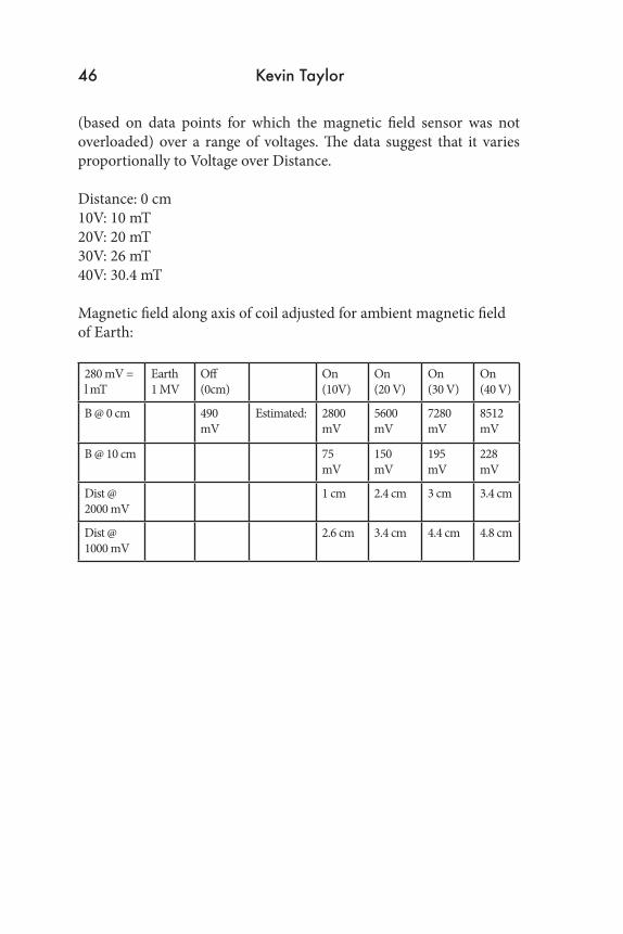
(based on data points for which the magnetic field sensor was not overloaded) over a range of voltages. The data suggest that it varies proportionally to Voltage over Distance.
Distance: 0 cm 10V: 10 mT 20V: 20 mT 30V: 26 mT 40V: 30.4 mT
Magnetic field along axis of coil adjusted for ambient magnetic field of Earth:
280 mV = l mT
Earth1 MV
Off (0cm)
On (10V)
On (20 V)
On (30 V)
On (40 V)
B @ 0 cm 490 mV
Estimated: 2800 mV
5600 mV
7280 mV
8512 mV
B @ 10 cm 75 mV
150 mV
195 mV
228 mV
Dist @ 2000 mV
1 cm 2.4 cm 3 cm 3.4 cm
Dist @ 1000 mV
2.6 cm 3.4 cm 4.4 cm 4.8 cm
46 Kevin Taylor
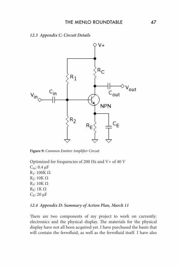
12.3 Appendix C: Circuit Details
Figure 9: Common Emitter Amplifier Circuit
Optimized for frequencies of 200 Hz and V+ of 40 V Cin: 0.4 µF R1: 100K Ω R2: 10K Ω R3: 10K Ω RE: 1K Ω CE: 20 µF
12.4 Appendix D: Summary of Action Plan, March 11
There are two components of my project to work on currently: electronics and the physical display. The materials for the physical display have not all been acquired yet. I have purchased the basin that will contain the ferrofluid, as well as the ferrofluid itself. I have also
THE MENLO ROUNDTABLE 47
begun to craft my electromagnets, using iron rebar for a core and many hundreds of turns in the wire. I have not yet ascertained that they will be adequate to provide the necessary field, but their strength is promising. What remains are the structures that will form the electromagnetic component of the display. I am attempting to use a few placeholders, such as a twisted coat-hanger (which will probably be unable to trap enough flux), extra rebar, and screws with large threads (with which I can observe ferrofluid being drawn upwards to greater flux). After testing, I have to consider which designs will be the most effective. The shapes I design should have some way to draw up ferrofluid along ridges so that the ferrofluid coats the entire shape when it becomes magnetized. I will visit junkyards to find appropriate parts if I can, and visit the Tech Shop to mill my own design if I can’t. Going forward with electronics, I will have to build or find a DC amplifier, and for the next generation of control tweak the Frequency-to-Voltage circuit to work well within the range of audio outputs. There are currently no showstoppers in sight.
48 Kevin Taylor