an atlas of cast gold procedures
TRANSCRIPT

8/11/2019 An Atlas of Cast Gold Procedures
http://slidepdf.com/reader/full/an-atlas-of-cast-gold-procedures 1/270
Preface
to the first edition
If the modern practice of dentistry were to be
suddenly deprived of the casting process, a serious
impasse would be created in our profession.
The restoration of lost tooth structure, the re-
placement of teeth by means of fixed and removable
partial denture prosthesis, and full mouth restorations,
in fact the practice of dentistry with our present-day
concept would be virtually impossible without the
dental casting process.
A textbook on the subject of the cast goldrestoration is difficult to write because of the require-
ments for exacting detail in the great number of steps
involved. Although over fifty-five years have elapsed
since the dental casting technique was made available
to the dental profession, teeth which are beautifully
restored with cast gold restorations are st i l l too few
in number -and this in spite of revolutionary advance-
ments in techniques, materials and teaching methods
since the inception of the dental casting procedure.
The casting of objects in gold by the wax
elimination process was used some four or five
thousand years ago by the Chinese. The famous Italian
artisan Benvenuto Cellini describes the use of this
method in making statues and rare artistic pieces as
early as the fifteenth century. Doubtlessly the
influence of his ancient art changed the course of
our profession.
Historically the men who have contributed to the
dental casting technique are legion; however, the
name of William H. Taggart i s synonymous with the
cast gold single tooth restoration. Dr. Taggart was of
an inventive nature and was continually experimenting
with methods and materials and eventually developed
a technique of casting gold inlays by the invested
wax pattern method which he announced to the
profession in 1907 - a dat e to be remember ed.
Taggart's announcement revolutionized not only the
single tooth restoration, but also made possible our
present concept of complete oral rehabilitation
employing a multiplicity of cast gold prostheses.
Although Dr. Taggart was general ly credited as
the originator of the dental casting process, others
had precelded him, principally Dr. B. F. Philbrook of
Denison, Iowa. In 1897, Dr. Philbrook read his
significant paper entitled "Cast Fillings." He was
ahead of his time and his work remained dormant
for nearly twenty years until after Taggart's revelation
to the profession. Even though Dr. Philbrook s ef fo rh
were not as complete as Dr. Taggart's method, it is
just and fit ting that he receive recognit ion for his
conitrib ution.
By our present standards, dental castings in this
pioneer period l ift much to be desired-they only
somewhat reproduced the original wax pattern and
fitted poorly. During this developmental period many
methods were used to improve the fit of the cast gold
inlays such as overlapping of the margins and
swaging.
In 1908, Dr. J. G. Lane of Philadelphia made a
valuable contribution by casting into a hot mould
using an investment with a high si l ica content which
resulted in batter fitting castings.
Following this in 1909, Dr. C. S. Van Horn dis-
covered the value of wax expansion whiclh was an
attempt to overcome the undesirable effects of
shrinkage of the gold alloy upon being cast.
During the ensuing years much work was done
by many men, especially Weinstein and Coleman,
who established the shrinkage of dental casting gold
alloys to be approximately 1.25 per cent. Later (1944)
Hollenback's scientific investigation of this problem
at Northwestern University resulted in slightly higher
values of shrinkage. With this knowledge, more
accurately fitting dental castings resulted by compen-
sating for the shrinkage of the gold upon being cast
by the use of wax expansion and by the use of
investments which permitted setting and thermal
expansion.
http://dentalbooks-drbassam.blogspot.com/

8/11/2019 An Atlas of Cast Gold Procedures
http://slidepdf.com/reader/full/an-atlas-of-cast-gold-procedures 2/270
In 1930, Dr. Carl Scheu of Lakewood, Ohio,
discovered the phenomenon known as hygroscopic
setting expansion. He found that plaster or casting
investments which are allowed to set in the presence
of water expanded in size, a discovery which played
an important role in the improvement of our casting
procedure.
As early as 1932, Dr. George M. Hollenback
consolidated the principles heretofore discovered and
developed a methodology which has proved to be
accurate to this day. The fidelity with which wax
patterns can now be reproduced in gold i s such that
any discrepancies in our final restorations must beattributable to the great number of steps in the gold
inlay procedure, and not to the casting process alone.
The history of the dental casting technique would
not be complete without proper reference to Dr. G. V.
Black, "The Grand Old Man of Dentistry." It was
during the latter part of Dr. Black's life that Dr.
Taggart revealed the casting process to the dental
profession. The fundamental principles of cavity
preparation laid down by Black were as vital to its
success then as they are today. Dr. Black was a rare
individual; his hand and mind are manifest in the
dental procedures of even the present.
It was inevitable that Dr. lngraham and Dr.
Koser, co-authors of " An Atlas of Gold Foil and Rubber
Dam Procedures," should combine theiir talents with
that of Dr. Russell Bassett to write this atlas text on
the cast gold restoration. The time was propitious: the
success of the gold foil atlas as a teaching aid showed
the need for a companion te,xt on the dental casting
procedure. The authors have combined their talents
in the field of clinical dentistry, research, skill, and
methodology of imparting knowledge to students at
the undergraduate and graduate levels.
Dr. lngraham i s that unusual individual who
performs as well as he teaches and teaches as well
as he performs-
his love for teaching and his constant
striving for perfection are spread throughout the pages
of this text. This profound desire for excellence of
performance and his years of experience as a dedi-
cated teacher have been the source of motivation
for many.
Many years of valuable clinical experience in
restorative dentistry coupled with years of post
graduate teaching have made Dr. Russell Bassett a
valuable contributor to this atlas. In practice he was
methodical and self -disciplined - much of the detailed
sequence of steps has been compiled by him. This
book has been completed because of his persistence
and efforts as a co-ordinator.
An atlas i s composed chiefly of detail illus
trations and their legends arranged in sequence to tel
a story. Dr. John Koser was a student and protege
of Dr. lngraham - he learned well the tenets of
excellence in restorative dentistry. Fortunately for this
atlas, Dr. Koser possesses a rare talent in the field
of art. It was because of his understanding of thefinest i n operative dentistry, combined with his artistic
talent that this beautifully illustrated text has been
made possible.
The proper use of an atlas of this type provides
even the beginning student with a method of
instruction so effective that through i t s application,
he is capable of producing an excellent result eve n
on his first attempt. This atlas is for the student and
the practitioner who wishes to advance his skill and
ability in a field that i s difficult to master. Neither
the vast fund of knowledge nor the manual ski l lsnecessary to master this field of endeavor can be
obtained by cursory reading or by one or two contacts
This highly illustrated atlas should be kept open
while working in the laboratory or at the dental chair,
until through the principles of reinforcement learning
each step has become automatic with the operator.
The dental casting process i s the giant link in
the chain of techniques needed in restorative dentistry.
Within this text are the means to do it well.
E. David Shooshan,
Pasadena, Calif.

8/11/2019 An Atlas of Cast Gold Procedures
http://slidepdf.com/reader/full/an-atlas-of-cast-gold-procedures 3/270
General Introduction
A sound approach to the restoration of the
single tooth provides the means for treating one of
the most frequent problems facing dentistry today.
Not only must the single tooth be restored to proper
function, but also the integrity of the supporting and
invesfing tissues must be safeguarded and protected.
This is accomplished by directing careful attention to
the anatomy, crown morphology, shape and size of
embrasures and position and shape of contact areas.
It i s obvious that the operator must master the
procedures for restoring the s i n g Ie tooth before
approaching the more complex problems involved in
extensive treatment such as full mouth reconstruction.
It is universally accepted that a l l successful dental
procedures must be based on thorough diagnosis and
treatment planning. Any concept of restorative
dentistry should be complete. I t should start with
diagnosis and end with the finished product func-
tioning in the mouth. If we think of operative dentistry
in this manner and consider the fundamental principles
involved and how to apply them, then the quality of
our dental health service will be improved. The restora-
tion of lost tooth structure with cast gold has been
selected as our example.
Any sound approach to mouth treatment must
be compatible with overall office economics. This
can be accomplished not only by understanding the
fundamentals and by mastering t he techniques
involved, but by carrying out these procedures in
their proper sequence. In this atlas, d e f i n i t e
standardized techniques have been presented. How-
ever, any sound procedures which do not violate
fundamental principles and have been proved to give
consistently satisfactory results may be used. Any
technique designed to produce consistently accurate
results must be based on fundamental principles. An
understanding of this philosophy w iI I permit theoperator to not only evaluate a technique but to
analyze the causes of the difficulties which he may
encounter. Each step in any procedure has equal
importance and although some steps are easier to
accomplish, the same careful attention must be given
to each one, or the end result will suffer, In making
a single tooth casting, using the indirect technique,
Each one of these transfers involves a number of
intermediate steps each of which must receive careful
attention. The maior steps from positive to negative
are:
1) Cavity preparation
2) Impression
3) Die
4) Wax pattern
5) Mold for casting
6) The gold casting
The two most difficult steps in making a cast gold
restoration are cavity preparation and fabrication of the
wax pattern. The transformation of the wax pattern into
a gold casting involves factors of time, temperature,weights and measures. If a standardized technique i s
carefully followed, uniformly good results can be
expected. Once the operator trains himself to vizualize
the finished product and the technique involved before
operating, the easier his task becomes. When fai lure
occurs, it i s essential to look back to determine which
fundamental has been violated. It i s not sufficient to
place the blame for failure on materials or techniques.
Success rests on the operator's ability to recognize
the requirements and limitations of each.
There has long been a need for a de ta i l edinstructional guide for carrying out the technical
procedures involved in cavity preparation, making
accurate impressions, fabricating accurate dies, con-
trolled waxing and casting techniques and finishing
the restorations. The Atlas approach, with i ts detailed
illustrations of technical procedures and its summary
of theoretical information, has proved to be the most
concise and effective instructional guide for under -
graduate and post-graduate teaching. It i s equally
valuable for the dental practitioner who desires
continued improvement in his ability to render an
outstanding health service to his patients.
It is axiomatic that dentistry should be able to
offer the finest possible health services to a l l patients.
Now that accurate simplified clinical and laboratory
procedures have been illustrated in d e ta i l and
presented in an Atlas, the profession should employ
this guide to provide the public with a more complete
and improved dental health service.
there are six major transfers from positive to negative. -The Authors

8/11/2019 An Atlas of Cast Gold Procedures
http://slidepdf.com/reader/full/an-atlas-of-cast-gold-procedures 4/270
CHAPTER
Diagnosing, Treatment Planning and TemporizingTo render a more effective hzalth service to the
patient, it i s necessary that a thorough comprehensive
diagnosis be made prior to the institution of any
treatment. This permits the dentist to practice pre-
ventive, as well as, restorative health service. Therehas been a tendency for the dental practitioner to
become so concerned with technical procedures and
how to accomplish them faster and perhaps better,
that he fa i l s to direct treatment toward the over -all
general health of the patient. It must be recognized
that the mouth is susceptible to various diseases which
influence the patient’s general health. Also, the mouth
often reveals systemic conditions, permitting the oper -
ator to make an early diagnosis of diseases which
would not otherwise be made.
Comprehensive diagnostic procedures can be
divided into two phases. First, the patient‘s medicalhistory and second, the examination of the oral cavity
and the associated structures. Regardless of the
patient‘s reason for seeking treatment, it is the re-
sponsibility of the dental practitioner to be thoroughly
informed regarding the patient’s general health and
well being. In making an examination of the teeth and
their adjacent and supporting structures, it must be
recognized that teeth do not function as individuals,
but as a complete dental unit which will contribute
either favorably or unfavorably to both oral and
systemetic health.
After making a general survey of the entire
mouth, a critical examination should be made for caries
and other diseases and abnormalties of the teeth and
their support ing structures. To make a critical examina-
tion, the dentist must make use of diagnostic aids.
Available diagnostic aids are as follows:
Periapical and bite-wing radiographs.
Study models.
Mirror and sharp explorer.
Pulp Test (electrical and thermal).
Percussion test.
Mobility test.
Periodontal probe.
Cellophane strip (1 I1000” and articulating ribbon.
Transillumination.
Ligature test (contact and embrasure relationships).
Biopsy and bacterial smear.
RADIOGRAPHS
Both periapical and bite-wing radiographs are
necessary to make a complete radiographic survey of
the teeth and adjacent bony structures. The following
conditions should be noted:
Size and abnormalities of the pulp chamber.
Extent and depth of penetration of caries.
Condition of existing restorations in the teeth.
Size and shape and number of roots.
Condition of the alveolar bone.
Width of periodontal spaces.
Presence of retained roots or foreign bodies.
Presence of impacted or unerrupted teeth.
Presence of radiolucent or radiopaque areas.
There are many conditions of both the teeth and
their supporting structures which cannot be determined
by a radiographic survey but are readily evident
through a clinical examination. Also, numerous con-
ditions which are evident in examination of the
radiographs must be verified by a clinical examinationusing a mirror, explorer, periodontal probe and other
diagnostic aids.
STUDY MODELS
Study models made from accurate impressions of
each arch are invaluable as diagnostic aids. It is
recognized that many conditions pertaining to the
individual teeth and their arches can be determined
by a critical examination of unmounted study models.
However, if study models are to be of value in studying
functional patterns, the models must be mounted on
an adjustable articulator in harmony with the patient’s
occlusal plane to reproduce correct hinge occlusion and
excentric relationships. Only in this manner can the
mechanical equivalents of jaw positions and relation-
ships of the teeth in occlusion be studied. In designing
the restoration for either a single tooth or a number
of teeth, the models should be studied to detect the
foIIow ing conditions:
Faulty proximal contact and embrasure relation-
ships (Ref. Chapter 14).
Faulty crown contours (Ref. Chapter 14).
Faulty marginal ridge relationship (Ref. Chapter
14).Malalignment of the teeth in their arches.
Worn or abraided occlusal and axial tooth surfaces.
Faulty margins and contours of existing restora-
tions.
Degree of overbite and overjet.
Edentulous areas.
Relationship of the gingival tissue to the clinical
crowns of the teeth.
Functional relationships of the teeth and their
arches in hinge occlusion and excentric positions.
1

8/11/2019 An Atlas of Cast Gold Procedures
http://slidepdf.com/reader/full/an-atlas-of-cast-gold-procedures 5/270
Properly oriented study models have many other
1) Equilibration of models as a guide for the removal
2) Prewaxing of models to determine cosmetic results.
3) Prewaxing of models to evaluate functional re-
4) Case presentation to the patient for educational
5) Prefabrication of acrylic temporaries.
valuable uses such as:
of occlusal interferences in patient‘s mouth.
lationships.
purposes.
It is recognized that the initial steps in making an
oral examination are accomplished with the mirror and
explorer, a careful radiographic survey and a detailed
examination of study models of the mouth. However,
to complete a critical examination of the teeth and
other structures in the oral cavity, it is imperative
that the operator not overlook the importance of
employing the other valuable diagnostic aids. Failure
of the operator to become thoroughly familiar with
al l conditions present in the mouth is responsible for
inadequate treatment planning.
TREATMENT PLANNING
When determining the material to be employed
the degree of permanency is of primary importance
however, the requirements for esthetics in some in
stances may influence the decision as to the materia
selected. For more extensive restoration of lost tooth
structure, cast gold is recognized as the material o
choice. The restoration of extensively involved anterio
and in some instances posterior teeth, however, re
quires the use of either a cast restoration in com
bination with porcelain or a full veneer porcelain
crown. This atlas includes a detailed description of the
designs for various types of intra-coronal and venee
cast gold restorations. The design or planning of each
individual preparation is dependent upon the purpose
the restoration is to serve. For example, restorations
which are to be used as abutments or for suppor
in splinting, require added resistance and retention
features. Cast veneer -type restorations are more ap
plicable for restoring faulty occlusion and altering the
axial contours of the crowns of the teeth.
Following a comprehensive diagnosis and
charting of a l l conditions found in the oral cavity, the
operator is now in a position to plan the treatment
of these conditions in proper consecutive order. Failure
to establish the proper sequence for treatment often
creates embarrassing situations and may create serious
economic problems both for the patient and the dentist.
Determining the proper sequence in which
treatment is to be carried out is an important factor
of treatment planning. A logical sequence for treatment
is as follows:
Relief of pain.
Elimination of infection.
Temporary correction of cosmetic impairment
(patient’s request).
Exploratory procedures to determine pulpal con-
ditions.
Initiation of necessary endodontic treatment.
Initiation of periodontal treatment.
Temporary correction of serious functional im-
pairment.
Removal of teeth indicated for extraction.
Equilibration when indicated.
Preliminary treatment of temporo-mandibular joint
disfunction.
Making the final treatment plan must be deferred
until a l l exploratory investigations and preliminary
treatments have been completed. At this time the
conditions of the mouth must be re-charted and the
sequence for carrying out restorative and other cor-
rective treatment necessary for restoring the mouth
to optimum health is determined. Consideration must
be given to the type and design of restorations indi-
cated for the individual teeth.
When making the final charting of the mouth
it is important that both the type of restoration to be
used and any special considerations in the design o
the preparation be noted on the chart. It will also be
found particularly useful to outline the individua
restorations on the study models.
Sound treatment planning provides an intelligen
and effective approach to patient education. Prope
evaluation of the patient’s temperament and attitudetowards receiving treatment is an essential part o
treatment planning. By carrying out the initial steps
in the plan of treatment, such as relief of pain and
exploratory procedures, the dentist can become thor
oughly acquainted with the patient’s interest in
receiving treatment and his capacity to cooperate
These are important factors in establishing both the
plan and a fee for oral health care for the patient.
The dentist is now in a position to make a fa
more practical plan of treatment for the individua
patient. Longer appointments are economically more
feasible for both the patient and the dentist. This
approach minimizes duplication of administering anes
thesia, making of impressions and temporizing. It mus
be recognized that the highly nervous or apprehensive
patient may not necessarily tolerate long appointments
Treatment planned over a longer period of time may be
more practical economically for some patients. In this
instance, if the most urgent treatment is taken care o
initially, the same final results in over -all health care
can be realized.

8/11/2019 An Atlas of Cast Gold Procedures
http://slidepdf.com/reader/full/an-atlas-of-cast-gold-procedures 6/270
It is essential to carefully plan each individual
appointment. With the availability of high-speed, in-
direct impression procedures and other improved
techniques, it i s advantageous to plan multiple prep-
arations of teeth. The types of restorative procedures
indicated should, where possible, be grouped together
in arranging patient appointments. Shorter operations,
such as the placement of silicates and amalgams or less
complicated inlays where direct wax pattern techniques
can be applied, may be utilized as fill-ins for time left
over from longer appointments. It is always advisable
to provide extra time within the appointment for the
planned treatment to avoid pressure on the operator.
It may be advantageous to carry out periodontal treat-
ment in the area of operation in conjunction with
operative procedures. In many instances, the improved
access to the interproximal area following the prepara-
tion of teeth makes it possible to treat the periodontal
lesion more effectively.
In a final analysis, the success realized in
carrying out the plan of treatment for dental health
care depends upon an intelligent case presentation to
the patient. It is at this time that a l l questions or
misundersandings in the patient’s mind must be clari-
fied. The exact plan of treatment, the time involved,
the fee and plan of payment must be thoroughly
understood and accepted by the patient. It is equally
important that the patient’s responsibility for co-
operation in accomplishing the outlined treatment be
explained and accepted. Promptness in keeping ap-
pointments and ca r ry ing out daily oral h yg ien e
procedures are a part of each patient‘s responsibility.The importance of periodic return visits to the dental
office for oral prophylaxis, maintenance and early
diagnosis must also be explair.ed to the patient at this
time. When these concepts and procedures are closely
adhered to, the patient - dentist relationship will be
both pleasant and economically sound.
TEMPORARY TOOTH PROTECTION
AFTER PREPARATION
Adequate temporizing of teeth prepared to
receive cast restorations is an essential step in modernoperative procedure. The application of a standardized
technique for fabricating temporary restorations is a
sound economic office procedure. It is also important
that patient comfort be maintained between appoint-
ments. It is also imperative that the health of the in -
vesting tissues, the relationship to the adjacent teeth,
and proper occlusion be maintained. A carefully con-
structed temporary restoration will prevent the teeth
from drifting or extruding over a period of several
weeks, keep the patient comfortable, and permit seda-
tive treatment of the pulp during the interim period.
Properly contoured temporary restorations will prevent
further irritation of the gingival tissues and will permit
these tissues to regain normal tonicity and relationship
to the finish line of the preparation.
Over -extended and improperly shaped temporary
crown-forms and temporary fillings cause inflammation
and possible tissue recession. This i s particularly true
when faulty temporary fillings are retained in themouth for an extended period of time. Similar injuries
may result from failure to remove excess temporary
cement which has been forced against or under the
free gingiva during the seating of the temporary
restorations. Inadequate temporary fillings can be
extremely uncomfortable and may become a factor in
losing patient confidence. Unnecessary return visits to
the office for the purpose of recementation or repair
of temporary restorations is economically unsound
for the patient and the dentist.
The benefits of adequate temporary protection
may be outlined as follows:1) To maintain patient comfort (prevent thermal
2) To minimize lateral or occlusal dri f l ing of the teeth:
3) To prevent unnecessary exposure of the prepared
teeth to mouth fluids.
4) To permit the pulp to be sedated between ap-
point ments.
5) To prevent irritation of the gingival tissues per -
mitting them to regain normal tonicity and
relationship to the finish line of the preparation.
6) To maintain temporary cosmetic appearance.
7) To provide the temporary restoration of function.
stimuIi).
Types of Temporary Tooth Protection
There are a number of types of temporary
coverage that can be utilized, the most common of
which are:
1 Acrylic restoration made from self -activating
2) Castings made from type 2 or 3 gold alloy.
3) Prefabricated plastic, aluminum, wrought silver
4) Zinc oxide eugenol cements wi th binders.
resins (cold cure).
and stainless steel crown forms.
Time has proved that the most satisfactory
approach to the initial temporizing of either single or
multiple preparations is the fabrication of cold cure
plastic restorations. If the technic for constructing these
plastic temporaries is coordinated in proper sequence
with routine operative procedures, no more chair time
will be required than for placing other types of tempo-
rary materials.
3
8/11/2019 An Atlas of Cast Gold Procedures
http://slidepdf.com/reader/full/an-atlas-of-cast-gold-procedures 7/270
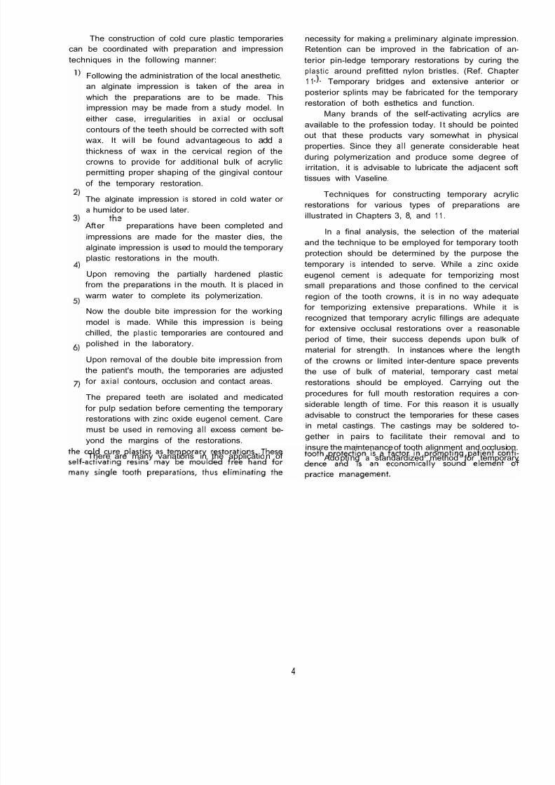
The construction of cold cure plastic temporaries
can be coordinated with preparation and impression
techniques in the following manner:
necessity for making a preliminary alginate impression.
Retention can be improved in the fabrication of an-
terior pin-ledge temporary restorations by curing the
Following the administration of the local anesthetic,
an alginate impression is taken of the area in
which the preparations are to be made. This
impression may be made from a study model. In
either case, irregularities in axial or occlusal
contours of the teeth should be corrected with soft
wax. It wi ll be found advantageous to add a
thickness of wax in the cervical region of the
crowns to provide for additional bulk of acrylic
permitting proper shaping of the gingival contour
of the temporary restoration.
The alginate impression i s stored in cold water or
a humidor to be used later.
Afterth?
preparations have been completed and
impressions are made for the master dies, the
alginate impression is used to mould the temporary
plastic restorations in the mouth.
Upon removing the partially hardened plasticfrom the preparations in the mouth. It is placed in
warm water to complete its polymerization.
Now the double bite impression for the working
model is made. While this impression i s being
chilled, the plastic temporaries are contoured and
polished in the laboratory.
Upon removal of the double bite impression from
the patient's mouth, the temporaries are adjusted
for axia l contours, occlusion and contact areas.
The prepared teeth are isolated and medicated
for pulp sedation before cementing the temporary
restorations with zinc oxide eugenol cement. Care
must be used in removing a l l excess cement be-
yond the margins of the restorations.
There are many variations in the application of
plastic around prefitted nylon bristles. (Ref. Chapter
1 1 . Temporary bridges and extensive anterior or
posterior splints may be fabricated for the temporary
restoration of both esthetics and function.
Many brands of the self -activating acrylics are
available to the profession today. I t should be pointed
out that these products vary somewhat in physicalproperties. Since they a l l generate considerable heat
during polymerization and produce some degree of
irritation, it is advisable to lubricate the adjacent soft
tissues with Vaseline.
Techniques for constructing temporary acrylic
restorations for various types of preparations are
illustrated in Chapters 3, 8, and 1 1 .
In a final analysis, the selection of the material
and the technique to be employed for temporary tooth
protection should be determined by the purpose the
temporary i s intended to serve. While a zinc oxide
eugenol cement i s adequate for temporizing mostsmall preparations and those confined to the cervical
region of the tooth crowns, it i s in no way adequate
for temporizing extensive preparations. While it is
recognized that temporary acrylic fillings are adequate
for extensive occlusal restorations over a reasonable
period of time, their success depends upon bulk of
material for strength. In instances where the length
of the crowns or limited inter -denture space prevents
the use of bulk of material, temporary cast metal
restorations should be employed. Carrying out the
procedures for full mouth restoration requires a con-
siderable length of time. For this reason it is usually
advisable to construct the temporaries for these cases
in metal castings. The castings may be soldered to-
gether in pairs to facilitate their removal and to
insure the maintenance of tooth alignment and occlusion.
Adopting a standardized method for temporary
4

8/11/2019 An Atlas of Cast Gold Procedures
http://slidepdf.com/reader/full/an-atlas-of-cast-gold-procedures 8/270
FABRICATION OF TEMPORARY COSMETIC SPLINT USING SELF- ACTIVATING RESIN*
Drifting of periodontally involved anterior teeth with . . . . . . serious cosmetic impairment.
The anterior teeth are cut off the cast of the patient's mouth,
reshaped, and repositioned in ideal alignment on the model.
A thickness of wax i s added to the labial and lingual surfaces
of the gingival areas of the teeth. An alginate impression
is taken of the cost and placed in a humidor.
Preparations are made on the cuspids and posterior teeth. The four anterior teeth are extracted. Dry foil may be placed
over the sockets. The crown portion of the alginate impression
i s filled with a proper mix of cold cure resin and . . .
Illustrations courtesy Dr. H. M. Tanner, Head of Department of Fixed Prosthodontics, University of Southern Cali forn ia School of Dentistry.
5

8/11/2019 An Atlas of Cast Gold Procedures
http://slidepdf.com/reader/full/an-atlas-of-cast-gold-procedures 9/270
. . . i s positioned in the mouth. The alginate impression is
removed at the proper time leaving the partially set acrylic
splint in the mouth.
The untr immed acrylic sp lint is loosened and removed from
the mouth just before it is completely hardened.
The splint is replaced in the mouth and occlusion i s adjusted
Note the relationship of the incisal and body shades of acryl
used. Esthetics were . . .
. . . improved by applying a small quantity of incisal shade
in the incisal portion of the alginate impression. The re-
mainder of the crown portion of the impression was filled
with body colored acrylic before it was placed in the mouth.
The temporary acrylic splint will insure patient comfor
esthetics and function unt il permanent restorations are co
structed.
6

8/11/2019 An Atlas of Cast Gold Procedures
http://slidepdf.com/reader/full/an-atlas-of-cast-gold-procedures 10/270
TEMPORARY BRIDGE RESTORATION USING SELF- ACTIVATING RESIN*
Soft wax i s added to the gingival third areas of the crowns
where mare thickness of acrylic i s desired for strength and
contour Th is may be done either in the mouth or on a
model - an alginate impression i s taken
The bridge or restorations to be replaced are removed from
the patients mouth.
The teeth are prepared for abutment restorations. The crown
portions of the abutment teeth and pontic area of the original
alginate impression are filled with cold -cure acrylic and placed
in the mouth.
The acrylic temporary i s removed from the teeth just before
it i s completely hardened. It is contoured, adjus ted far occlu-
sion, and polished before being temporarily cemented.
Illustrations courtesy Dr. H. M. Tonner, Head of Department of Fixed Prosthodontics, University of Southern California School of Dentistry.
7

8/11/2019 An Atlas of Cast Gold Procedures
http://slidepdf.com/reader/full/an-atlas-of-cast-gold-procedures 11/270
CAST GOLD SPLINTS USED FOR PROTECTING AND STABILIZING
TEETH DURING FULL MOUTH RECONSTRUCTION PROCEDURES
Temporary acrylic splints are fabricated immediately after the
preparations on the teeth are completed and . . .
At the first appointment impressions ore made of the preparedteeth and opposing occlusion. A hinge occlusion mounting i s
mode for the purpose of . . .
. . . provide tooth protection between the patient's first an
second appointments.
. . . constructmg temporary cast gold splints. The gold castings can be more accurately adlusted to occlusion.
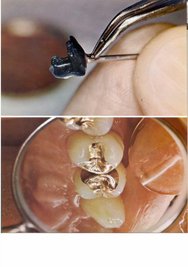
TOP PLATE
Cold cure plastic temporary restoration for MOD onlay
preparation.
By soldering the castings into pairs they can be stabilized,
thus preventing slight movements which would be detrimental
in full mouth reconstruction procedures.
BOTTOM PLATE
Temporary cold cure plastic restoration for maxillary
central incisor using nylon bristles to aid retention.
8

8/11/2019 An Atlas of Cast Gold Procedures
http://slidepdf.com/reader/full/an-atlas-of-cast-gold-procedures 12/270
8/11/2019 An Atlas of Cast Gold Procedures
http://slidepdf.com/reader/full/an-atlas-of-cast-gold-procedures 13/270
CHAPTER
The Proximo - Occlusal Intra Coronal Inlay Restoration and
Direct Wax Pattern Technic.
Introduction
The restoration of a tooth with gold, amalgam,
porcelain or any other acceptable material, can be no
better than the preparation designed for it. The cavity
prepared to receive a gold inlay should not only be
designed to gain perfection of margins and restore
occlusion, but should be engineered to augment the
strength of the tooth as well. Good cavity preparation
is the foundation for successful operative dentistry.
Diagnosis of the conditions or involvements of
the tooth, such as caries, erosion, mal-alignment,
resistance to caries and other environmental conditions,
are factors indicating the type of restoration required.
Many failures can be traced directly to faulty diagnosis.
Sound oral health treatment is based upon thorough
diagnosis and treatment planning. Before initiating any
operative procedure, the dentist should have a com-
plete set of peri-apical and bite-wing roentgenographs.
Study models made from accurate impressions are also
invaluable as diagnostic aids.
Gold alloy, by nature of its physicalprope,rties,
differs greatly from amalgam. While amalgam must
rely upon surrounding walls for support, this i s not
necessarily true of the gold restoration. The gold
casting should, whenever possible, impart strength
to remaining tooth structure by binding together
all of i t s component parts. I ts toughness and high
tensile strength permit the making of restorations
that will resist forces of mastication to a much greater
degree than does amalgam or gold foil. Also, toothform can be more perfectly and more readily restored
by the cast goldrelstoration
than by any other material.
In cavity preparation, care should be taken at
all times to avoid heat. The possibility of over -heating
a tooth, using diamond and carbide burs, wi th the
greatly increased rotational speeds, i s greater today
than ever before. We should all recognize the possi -
bility of injury to the pulp. Teeth may be kept
sufficientlycool
by use of a mixture of air and
water, or by a stream of water directed on the tooth.
When water i s used it acts as a lubricant and it will
be found that burs and stones cut more efficiently
and do not clog, and preparations will berelativeily
clean when finished.
If any operative procedure is to be a success,
the dentist must have clearly fixed in his mind all
fundamentals which constitute the finished operation.
Success i s measured first, by the safeguarding of thepulp; second, by the efficiency with which lost tooth
structure is replaced and recurrence of caries pre -
vented; t hi rd , b y the restoration of masticatory
function; fourth, by due consideration of esthetic
requirements; and last, but by nomeans
least, by the
reproduction of tooth form and contour to promote
and maintain tissue health.
FUNDAMENTALPRlNiClPLES
OF CAVITY DESIGN
Bucco Lingual
Outline Form
One of the most significant requirements for a
successful inlay restoration i s the pr in c ip le of
extension for prevention. The highly variable qualities
of inlay waxes and impression materials require that
ample access to or beyond the angles of the tooth be
provided to facilitate the manipulation and removal
of these materials. Likewise, access for the proper
finishing of the margins of a casting on the tooth
figures strongly on the life of the restoration. Being
aware of these facts and knowing that the slightest
discrepancy of an inlay margin may result in failure,
we must conclude that it is essential for the operator
to a I Io w f o r convenience commensurate with hisability to work efficiently.
While it is necessary to confine the extensions
of the bucco-proximal walls of inlay preparations on
the
mesial surfaces of first and second bicuspids and
first molar teeth because of esthetics, it should be
pointed out that increased extensions of all proximal
walls i s desirable in the most posterior teeth for
convenience to work with ease and efficiency in these
more inaccessible areas in the mouth.
10

8/11/2019 An Atlas of Cast Gold Procedures
http://slidepdf.com/reader/full/an-atlas-of-cast-gold-procedures 14/270
ILLUSTRATION No. 1
Buccal and lingual outline form i s governed by convenience to work
with ease and efficiency especially in the more inaccessible areas
of the mouth. It i s advisable to minimize the mesio-buccal outline
form fior esthetics (x). Draft for withdrawal of impression or pattern
i s provided through greater extension and convenience of the disto-
buccal and lingual outline form y ] . Greater extension of buccal
and lingual oukline form is indicated when preparing the more
inaccessible second and third molar teeth I).
Gingival Outline Form
The gingival wall is usually established at ap-
proximately a right angle to the long axis of the tooth
and along with its bevel i s generally placed about one
mill imeter below the free margin of the gingiva when
the tissue i s in normal relationship to the coronal
portion of the tooth.
ILLUSTRATION No. 2
The gingival margins placedl m m
under the free gingiva when
gingival tissue i s in normal relation to crown of tooth.
It must be pointed out that in instances when
there has been excessive recession of the investing
and supporting structures because of necessary surgery
or pathological destruction, it will not always be
advisable to place the gingival wall under the free
margin of the gingiva. Excessive extension of the
gingival wall with its bevel, especially on tapered
bell-shaped teeth, wi ll often necessitate gross over -
extension of outline form to eliminate axial outside
undercuts in the gingival third area of the preparation.
ILLUSTRATION No. 3
A. The gingi val margins may sti ll be placed under the ptotection of
the free gingiva where conditions of limited gingiva81 recessions
are present.
B. Where excessive gingival tissue recession occurs it will not
always be practical to place the gingival margin under the free
gingiva.
C. Overcuthing of the tooth results from the attempt to place the
gingival margin under the free gingiva when excessive gingival
reaession i s present.
The Gingival Bevel
It is desirable to place a bevel of approximately
45 degrees on the gingival wall of all inlay prepara-
tions. An adequate gingival bevel will eliminate the
possibility of leaving weak or unsupported enamel
on this wall. It provides a stronger obtuse angle of
tooth structure which will facilitate finishing of the
casting and i s a design which lends itself to a more
efficientstealing
of the margins of the restoration. The
gingival bevel should include one-half the width of
the gingival wall. Gingival bevels greater than 45
degrees may result in over -extension of the gingival
and proximal margins, thus increasing the difficulty
of impression making, fabricating the waxpawern
and finishing of the restoration.
A -
B-
1LLUSTRATlON
No. 4
(A) Represents a bevel of approximately 45 degrees. The dotted
line (B) l lustrates agingival bevel steeper than 45degrees which
may result in over -extension of the gingival and proximal margins.
8/11/2019 An Atlas of Cast Gold Procedures
http://slidepdf.com/reader/full/an-atlas-of-cast-gold-procedures 15/270
It must be pointed out that in instances where the
gingival extension of restorations cannot be placedunder the protection of the free gingiva, it is the
obligation of the operatoro
properly educate the
patient in the importance of thorough and effective
mouth hygiene practices for keeping these root
surface areas clean.
Occlusal Outline Form
The width of the isthmus portion of the prepara-
tion on the occlusal surface of the tooth should be
maintained to a minimal extension for conservation
of tooth structure. It should, however, include any
faulty pits and fissures in the surface of the tooth.
At the same time the out line form should be carried
onto smooth areas of the buccal and lingual slopes
of the cusps of the tooth. This extension will place
the margins of the casting in areas where they may be
easily finished.
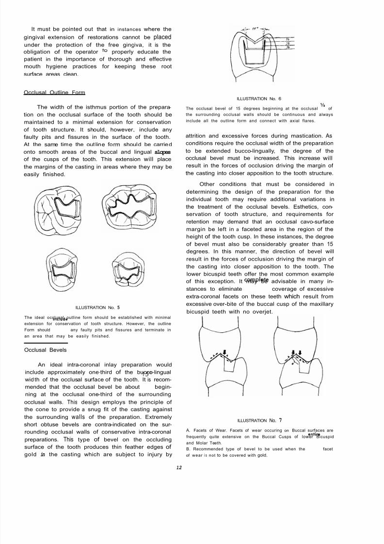
ILLUSTRATION No. 5
The ideal occlusal outline form should be established with minimal
extension for conservation of tooth structure. However, the outline
Form should includme any faulty pits and fissures and terminate in
an area that may be easily f inished.
Occlusal Bevels
An ideal intra-coronal inlay preparation would
include approximately one-third of the bucco-lingual
width of the occlusal surface of the tooth. It is recom-mended that the occlusal bevel be about
15'
begin-
ning at the occlusal one-third of the surrounding
occlusal walls. This design employs the principle of
the cone to provide a snug fit of the casting against
the surrounding walls of the preparation. Extremely
short obtuse bevels are contra-indicated on the sur -
rounding occlusal walls of conservative intra-coronal
preparations. This type of bevel on the occluding
surface of the tooth produces thin feather edges of
gold in the casting which are subject to injury by
ILLUSTRATION No. 6
The occlusal bevel of 15 degrees beginning at the occlusal /3 of
the surrounding occlusal walls should be continuous and always
include all the outline form and connect with axial flares.
attrition and excessive forces during mastication. As
conditions require the occlusal width of the preparation
to be extended bucco-lingually, the degree of the
occlusal bevel must be increased. This increase will
result in the forces of occlusion driving the margin of
the casting into closer apposition to the tooth structure.
Other conditions that must be considered in
determining the design of the preparation for the
individual tooth may require additional variations in
the treatment of the occlusal bevels. Esthetics, con-
servation of tooth structure, and requirements for
retention may demand that an occlusal cavo-surface
margin be left in a faceted area in the region of the
height of the tooth cusp. In these instances, the degree
of bevel must also be considerably greater than 15
degrees. In this manner, the direction of bevel will
result in the forces of occlusion driving the margin of
the casting into closer apposition to the tooth. The
lower bicuspid teeth offer the most common example
of this exception. It may be advisable in many in -
stances to eliminatecomplelte
coverage of excessive
extra-coronal facets on these teeth which result from
excessive over -bite of the buccal cusp of the maxillary
bicuspid teeth with no overjet.
ILLUSTRATION No. 7
A. Facets of Wear. Facets of wear occuring on Buccal surfaces are
frequently quite extensive on the Buccal Cusps of lower Bicuspid
and Molar Teeth.
B. Recommended type of bevel to be used when the entire facet
of wear i s not to be covered with gold.
12
8/11/2019 An Atlas of Cast Gold Procedures
http://slidepdf.com/reader/full/an-atlas-of-cast-gold-procedures 16/270

8/11/2019 An Atlas of Cast Gold Procedures
http://slidepdf.com/reader/full/an-atlas-of-cast-gold-procedures 17/270
Slight undercuts in the internal portion of the
preparation may be compensated for in the waxingprocedures. However, there is no way to compensate
for an outside axial undercut of the proximal margins.
If there are marginal axial undercuts in the prepara-
tion, the wax pattern will be distorted or fractured
during withdrawal.
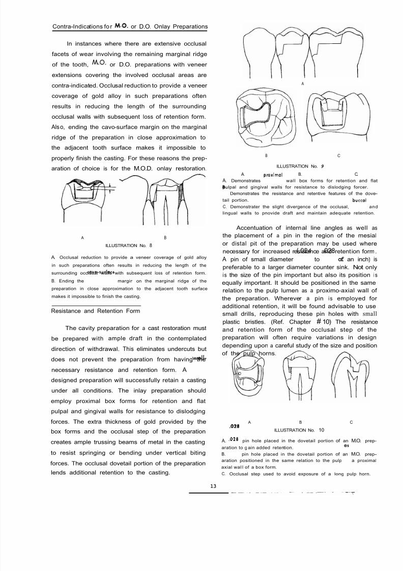
ILLUSTRATION No. 1 1
This illustration demonstrates axial, outside, marginal undercut (A)
which cannot be compensated for in the wax pattern or casting.
The axial flares and the gingival bevels of the
preparation should connect in a graceful curve withoutundercuts. These flares should be flat planes and
should form a definite, sharp cavo-surface angle with
the outside surface of the tooth. The gingival margin
trimmer is recommended as the most ideal instrument
for placing gingival bevels on inlay preparations. The
design of this instrument provides control in estalb-
lishing the angle of the gingival bevel without
possibility of injuring the adjacent tooth. The gingival
bevels may be established with specially designed
diamond rotary instruments. Caution should be used
with the long flame-type diamond as it i s apt to
produce too long a gingival bevel. Before using
rotary instruments they should be carried to the tooth
in the contra-angle handpiece. Without running the
motor the following observations should be made:
1
Will these instruments injure the adjacent tooth?
2) Will these instruments create an undesirably
long gingival bevel?
If the answers to these questions are in the
affirmative, then it will be found more desirable to
establish the gingival bevels with keen, sharp gingival
margin trimmers and the proximal flares with XX
coarse wet-0-dry discs. Before using wet-0-dry discs
they should be run at an angle against the truingstone to remove the abrasive at the edge. This will
prevent cutting a V shaped notch when connecting
the axial flares with the gingival bevel. The axial
flares should be flat and sharp. Caution should be
taken in any attempt to polish the cavo-surface margins
since this procedure might round these margins with
a subsequent loss of sharpness and detail. In using
the gingival margin trimmers, defin ite finger rests
and controlled pressure are imperative. The ideal
gingival bevel should be approximately 45 degrees
starting at one-half the width of the ideal gingival
margin trimmer may be altered to obtain this ideal
result. It can be pointed out that where access permits,
a Weidelstat chisel i s an excellent adjunct for instru-
menting the gingival bevel on the mesial surface of
the preparation and in some instances the distal as
well. It is always helpful to establish the gingival
bevels before instrumenting the proximal flares.
wall. The angle of the cutting edge of the gingival
ROOT SURFACE
A )
B
C D
E
ALTERED ALTERED \ REGULAR
BEVELILLUSTRATION No. 12
A. The ideal gingival bevel should not be over 45 degrees starting
at one-half the width o f the ideal gingival wall.
B The gingival bevel may be established with a bud-shaped
diamond rotary instrument or a razor -sharp gingival margin trimmer.
C. 54VS
Special designed gingival beveler.
D. The notary instrument may be contraindicated because of lack
of access and the danger of placing too long a gingival bevel or
injuring the adiacent tooth. The gingival margin trimmer may be
used to advantage in developing the gingival bevel in there
situations.
E. Regular and modif ied cutt ing edge of the gingival margin trimmer
used to obtain the desired 45-degree bevel.
As a rule of thumb the surrounding margins of
a preparation designed to receive a cast gold restora-
tion should form an obtuse angle with the surface of
the tooth. This provides the advantage of being able
to finish an acute angle of tough malleable gold alloy
against an obtuse angle of more friable tooth structure.

8/11/2019 An Atlas of Cast Gold Procedures
http://slidepdf.com/reader/full/an-atlas-of-cast-gold-procedures 18/270
VARIATIONS IN THE DESIGN OF PROXIMO-OCCLUSAL
INNLAYPREPARATIONS.
In instances where caries, abrasion, erosion or
other iniuries have seriously weakened the coronal
portion of the tooth, variations in the design of the
preparation for proximo-occlusal inlay restorations 'may
be necessary tostrengtheln the structural elements of
the tooth.
ILLUSTRATION No. 13
D.O. and M.O.D. intra-coronal preparations in a mandibular first
molar including the disto-buccal cusp.
ILLUSTRATION No. 14
D.O. and M.O.D. intra-coronal preparations in a maxil lary molar
including the disfo-lingual cusp.
ILLUSTRATION No. 15
Weak mesio-buccal cusps should always be
occlusal preparations in maxillary molar teeth.
protected in proxim
When the preparation i s completed there shou
be a thorough prophylaxis of the prepared toofh an
the adjacent teeth before making the impression. Th
i s accomplished by scaling the teeth and then polishin
with a rubber cup or a soft end brush using fine w
pumice. If the polishing is done carefully with a lig
touch there will be no injury to cavo-surface margin
Stone dies made from the hydrocolloid impression w
be much sharper which will facilitate fabricating a
accurate wax pattern.

8/11/2019 An Atlas of Cast Gold Procedures
http://slidepdf.com/reader/full/an-atlas-of-cast-gold-procedures 19/270
ARMAMENTARIUM FOR PROXIMO-OCCLUSAL PREPARATION AND
DIRECT WAX PATTERN
PREPARATION
700 - 701 TAPER FISSURE BUR
900 - SERIES END CUTTING BUR
699 X LONG TAPER FISSURE BUR
BIN- ANGLE CHISEL
MODIFIED FLAME SHAPED DIAMOND STONE
SMALL ROUND END TAPER DIAMOND STONE
WEIDELSTADT CHISEL
GINGIVAL MARGIN TRIMMERS
X AND XX COARSE WET-0-DRY DISCS
WHITE POLY-STONE
SPRAY BOTTLE WITH 3% HYDROGEN PEROXIDE
WAX PATTERN
EGG BURNISHER
3 HOLLENBACK CARVER
3 EXPLORER
ACETONE
COTTON
MINERAL OIL
HARD INLAY WAX
MATRIX BAND AND HOLMR
1&GAUGE SPRUE
KERR'S WAX-UP WAX
RED COUNTER WAX
SEWING THREAD
FINE SOFT S I K
16

8/11/2019 An Atlas of Cast Gold Procedures
http://slidepdf.com/reader/full/an-atlas-of-cast-gold-procedures 20/270
PROCEDURES FOR THE PROXIMO-OCCLUSALINlLAY
PREPARATION
Position of tapered fissure bur to start occlusal opening. Make occlusal opening . . .
occlusal outline form same as Class I preparation. Angulation of tapered fissure bur to
. . . reduce marginal ridge area to level of pulpal floor. Angulation of tapered fissure bur
l Y

8/11/2019 An Atlas of Cast Gold Procedures
http://slidepdf.com/reader/full/an-atlas-of-cast-gold-procedures 21/270
. . . to rough out proximal box form.
Rest shank of end cutting bur against adjacent tooth
Angulation of end cutting bur.
. . . and smooth gingival floor.
Angulat ion of 699X long tapered fissure bur to . . . start proximal line angles.

8/11/2019 An Atlas of Cast Gold Procedures
http://slidepdf.com/reader/full/an-atlas-of-cast-gold-procedures 22/270
Position of 699X long bur to start bucco-axial line angle. Position of 699X long bur to start linguo -axial l ine angl
Instrument bucco-proximal l ine angle with bin -angle chisel. Instrument linguo-proximal l ine angle with bin -angle chise
Instrumented proximal line angle. Before making the gingival bevel, try various rotary instru
ments without running the motor . . .
19

8/11/2019 An Atlas of Cast Gold Procedures
http://slidepdf.com/reader/full/an-atlas-of-cast-gold-procedures 23/270
. . . to determine which instrument w il l reproduce o 45
beveland
not injure the adjacent tooth.
It i s not always possible to use a rotary instrument to
establish an ideal gingival bevel. AlternateMethod-angulo-
tion of Weidelstadt chisel to start the gingival bevel.
Making gingival bevel with Weidelstadt chisel. Angula tion of gingival margin trimmer.
Gingival margin trimmer in action. Slide gingival margin trimmer down linguo -proximal wall . . .
20

8/11/2019 An Atlas of Cast Gold Procedures
http://slidepdf.com/reader/full/an-atlas-of-cast-gold-procedures 24/270
. . . until it reaches the linguo-gingival corner of the
gingival floor.Using the lingual wall as a fulcrum, establish the gingi
bevel three-fourths distance toward the bucco-gingival an
of the gingival floor.
~
Slide gingival margin trimmer down bucco-proximal wall . . .
Using the buccal wall os a fulcrum, establish the gingival
bevel three-fourths the distance toward the linguo-gingival
angle of the gingival floor.
21
. . . until it reaches the bucco-gingival corner of th
gingival floor.
Establish the proximal flares with o Weidelstadt
8/11/2019 An Atlas of Cast Gold Procedures
http://slidepdf.com/reader/full/an-atlas-of-cast-gold-procedures 25/270
or bin-angle chisel The use of hand cutting instruments will produce o sharp
flat plane and permit minimol
extension of theproximo1
flares.
Use a truing stone to dull the edge . . . . . . of a coarse Wet-0 -Dry disc.
Try the Wet -0-Dry disc without running the motor - for
proper angulation and direction.
A third technique for establishing the proximal flare and
connecting the gingival bevel.
22

8/11/2019 An Atlas of Cast Gold Procedures
http://slidepdf.com/reader/full/an-atlas-of-cast-gold-procedures 26/270
Reshape white poly stone on the stone truer.
of the height of the surrounding occlusal walls.
flares,
c
Afte r the tooth and its preparotion have been cleaned wi th
fine wet pumice, use three percent hydrogen peroxide in a
spray bottle.
Finished preparation with internal and external detail.
Spray hydrogen peroxide into the preparation and under a
surrounding gingival tissues, until the tissues are blanched
This procedure will minimize the problems of tissue retractio
when using any indirect impression technique.
23
at occlusFFtntilirh stortingr r uw d greerr v r l
f i f t n
8/11/2019 An Atlas of Cast Gold Procedures
http://slidepdf.com/reader/full/an-atlas-of-cast-gold-procedures 27/270
PROCEDURES FOR MAKING A DIRECT WA X PATTERN
While the modern materials for making an in-
direct impression and fabricating an accurate die of
the preparation provide an easier approach for making
accurate fitting multiple restorations, it is often eco-
nomically more practical to utilize the direct pattern
technique for making a single tooth casting. If the
operator has acquired a high degree of skill in thedirect technique, castings may be made with the ut-
most accuracy and refinement. While there are many
good techniques for making a direct wax pattern, our
presentation will be limited to one standardized pro-
cedure which has been proved to produce consistently
acceptable results over a long period of time.
The technique illustrated i s directed toward fabri-
cating the wax pattern of a proximo-occlusal prepara-
tion. It wi ll also be found that occlusal and gingival
cast restorations may be made in a more economical
way by using the direct technique.

8/11/2019 An Atlas of Cast Gold Procedures
http://slidepdf.com/reader/full/an-atlas-of-cast-gold-procedures 28/270
PROCEDURES FOR MAKING A DIRECT WAX PATTERN FOR PROXIMO-OCCLUSAL INLAY RESTORATION
Lava testing die with M.O. intra-coronal preparation. Armamentarium for direct wax pattern. Left to right: burnishe
Hollenback carver, No. 3 explorer, acetone, mineral o
cotton, inlay wax, matrix band and holder, sprue, wax-u
wax and red counter wax.
A special matrix i s cut with the desired arc or curvature
from a sheet of one, one-thousandth shim steel if the ready-
made matrix is not adaptable.
Two ready-made matrices; lower specially cut matrix.
Fit matrix around prepared tooth and hold in position with
a suitable matrix holder.
25
Contour matrix with a round tapered burnisher.

8/11/2019 An Atlas of Cast Gold Procedures
http://slidepdf.com/reader/full/an-atlas-of-cast-gold-procedures 29/270
Lubricate matrix and piece of paper with mineral oil. Heat a stick of hard inlay wax in a flame
. . . and drip molten wax into lubricated matrix. Completely fill matrix with molten wax.
Al lo w wax to cool
2G
. . . until the surface of the wax has lost its sheen.

8/11/2019 An Atlas of Cast Gold Procedures
http://slidepdf.com/reader/full/an-atlas-of-cast-gold-procedures 30/270
8/11/2019 An Atlas of Cast Gold Procedures
http://slidepdf.com/reader/full/an-atlas-of-cast-gold-procedures 31/270
Use a warm egg burnisher to further refine the occlusal
contour of the wax pattern.
Hold wax pattern in place with the egg burnisher and further
refine embrasure and axial margin contour.
pattern . . .
thus readapting the wax in this area. Hold the pattern firm ly in place with the egg burnisher.
Burnish and remove any excess wax over the axial margins
with a warm Hollenback waxing instrument.
8/11/2019 An Atlas of Cast Gold Procedures
http://slidepdf.com/reader/full/an-atlas-of-cast-gold-procedures 32/270
Pass a fine strand of sewing thread through the contact area. While holding the pattern in place with the egg burnish
smooth the inter -proximal surface of the pattern with fi
soft silk.
Use a cotton pellet with acetone . . . to smooth all surfaces of the wax pattern.
Attach a right-angled explorer to the center of the wax
pattern . . .
. . . and remave in the most favorable line of shed.
29
8/11/2019 An Atlas of Cast Gold Procedures
http://slidepdf.com/reader/full/an-atlas-of-cast-gold-procedures 33/270
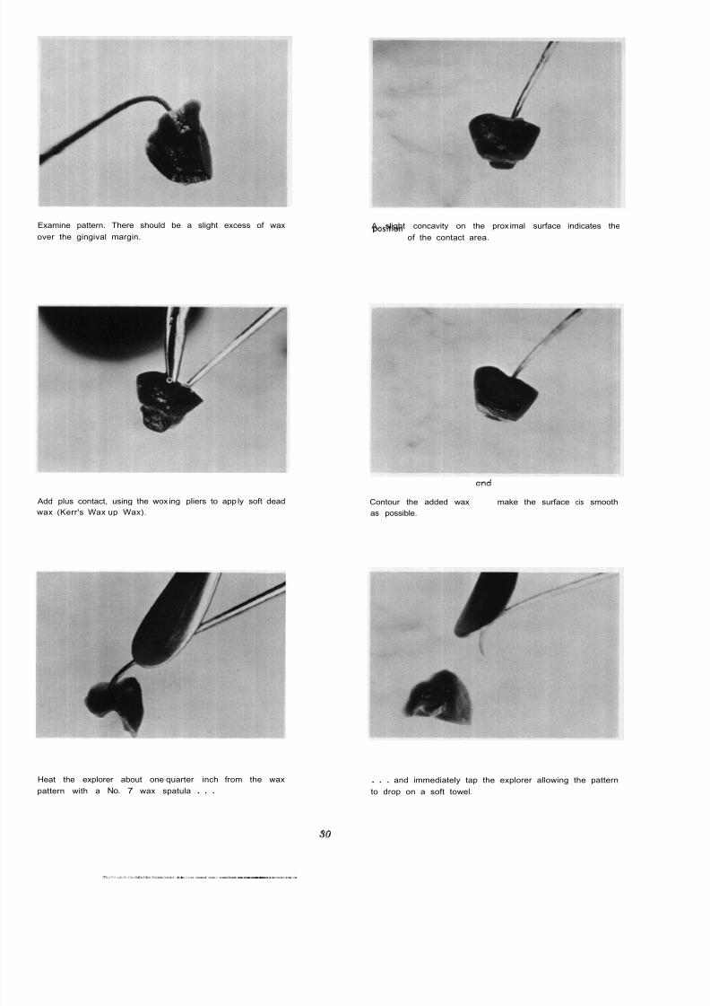
Examine pattern. There should be a slight excess of wax
over the gingival margin.
Add plus contact, using the wox ing pliers to app ly soft dead
wax (Kerr's Wax-up Wax).
Heat the explorer about one-quarter inch from the wax
pattern with a No. 7 wax spatula . . .
A slight concavity on the prox imal surface indicates the
position of the contact area.
Contour the added wax and make the surface cis smooth
as possible.
. . . and immediately tap the explorer allowing the pattern
to drop on a soft towel.
3

8/11/2019 An Atlas of Cast Gold Procedures
http://slidepdf.com/reader/full/an-atlas-of-cast-gold-procedures 34/270
8/11/2019 An Atlas of Cast Gold Procedures
http://slidepdf.com/reader/full/an-atlas-of-cast-gold-procedures 35/270
8/11/2019 An Atlas of Cast Gold Procedures
http://slidepdf.com/reader/full/an-atlas-of-cast-gold-procedures 36/270
CHAPTER
M.O.D. Inlay and Onlay Restorations
THE M.O.D. INTRA-CORONAL RESTORATION
In mouths where the occlusion is favorable and
where there i s evidence of only limited abrasion, an
intra-coronal M.O.D. type preparation with conserva-
tive extensions of occlusal outline form is indicated.
Extension of outline form on the occlusal surface must
always include any faulty pits and fissures and must
be carried onto smooth areas of the curved inclines
of the cusps of the teeth to facilitate proper finishing
of the restoration. Extensions for the proximal outline
form as well as al l other fundamental principles of
cavity design have been described in detail in the
chapter on "The Proximo-Occlusal Intra-Coronal Inlay
Restoration . . . (See Chapter2
A A
B B
isthmus portion of the preparation. The general effectof the typical intra-coronal type preparation in such
instances is to create extremely long cusps rising above
the occlusal wall of the preparation with little sup-
porting dentin. Theseweakeneld
or unsupported cusps,
unless protected, are subiecteld to stresses which tend
to bend or fracture them at their point of attachment
with the pulpal wall of the preparation. While an ac-
tual fracture may not occur, the springing apart of
these weakened cusps may open the margins of the
restoration causing failure.
A.
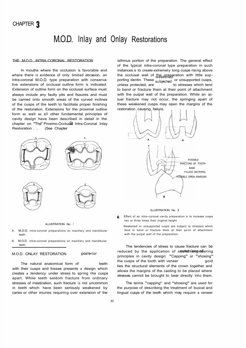
ILLUSTRATION No. 1
A. M.O.D. intra-coronal preparations on maxil lary and mandibular
8
teeth.
B. M.O.D. intra-coronal preparations on maxil lary and mandibular
teeth.
M.O.D. ONLAY RESTORATION
I I
POSSIBLE
FRACTURE OF TOOTH
BASE
FILLING MATERIAL
POSSIBLE OPEN MARGIN
ILLUSTRATION No. 2
Effect of an intra-coronal cavity preparation is to increase cusps
two or three times their original height.
Weakened or unsupported cusps are subject to stresses which
fend to bend or fracture them at their po int of attachment
with the pulpal wall of the preparation.
The tendencies of stress to cause fracture can be
reduced by the application of sound engineering
principles in cavity design. "Capping" or "shoeing"
the cusps of the tooth with veneer efxtensions
of
gold
ties the structural elements of the crown together and
allows the margins of the casting to be placed where
stresses cannot be brought to bear directly into them.
The natural anatomical form of postelrior teeth
with their cusps and fossae presents a design which
creates a tendency under stress to spring the cusps
apart. While teeth seldom fracture from ordinary
stresses of mastication, such fracture i s not uncommon The terms "capping" and "shoeing" are used for
in teeth which have been seriously weakened by the purpose of describing the treatment of buccal and
caries or other iniuries requiring over extension of the lingual cusps of the teeth which may require a veneer
33
8/11/2019 An Atlas of Cast Gold Procedures
http://slidepdf.com/reader/full/an-atlas-of-cast-gold-procedures 37/270
extension or coverage of gold. "Capping" refers to the
complete coverage of the cusp or cusps of a tooth with
sufficient extension of the bevel onto the buccal or
lingual surfaces of the tooth to carry the margin of
the restoration into areas where stresses cannot be
brought to bear directly into them.
The term "shoeing" refers to a veneer coverage
of the cusp of a tooth with only a slight finishing
bevel on the crest of the cusp. This bevel should be
established either at a right angle to the long axis of
the tooth or in a slight reverse direction. In this manner
the rule for establishing an obtuse angle of tooth
structure on all the margins of a preparation for
greater strength and resistance of cavo-surface margins
i s fulf illed. It should be pointed out that in instances
where the buccal cusp of a maxillary or the lingual
cusp of a mandibular tooth has been greatly welakened
due to loss of tooth structure, this finishing bevel
should in these instanceis be established in a reverse
direction to tie the structural elements of the crown
together.
....'
CORRECT CORRECT INCORREC T
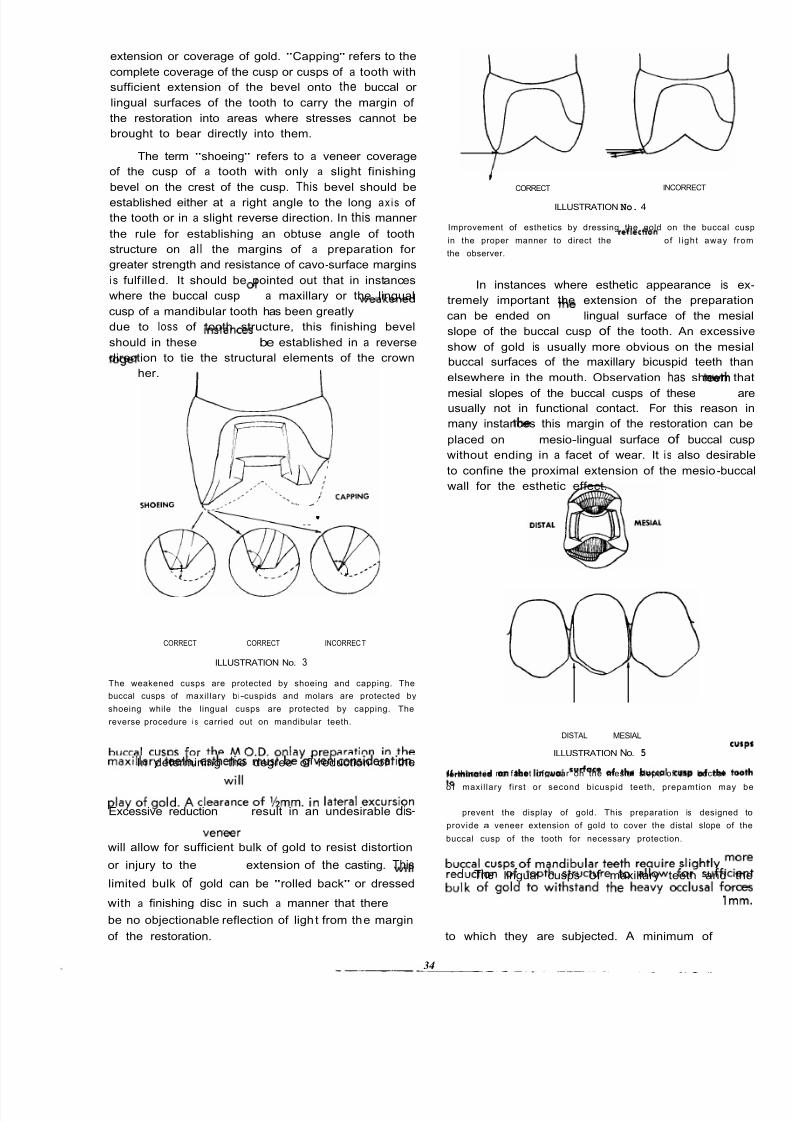
ILLUSTRATION No. 3
The weakened cusps are protected by shoeing and capping. The
buccal cusps of maxil lary bi-cuspids and molars are protected by
shoeing while the lingual cusps are protected by capping. The
reverse procedure i s carried out on mandibular teeth.
INCORRECTCORRECT
ILLUSTRATION No. 4
Improvement of esthetics by dressing the gold on the buccal c
in the proper manner to direct the d l ec t i on of l ight away f r
the observer.
In instances where esthetic appearance is e
tremely important the extension of the preparati
can be ended on the lingual surface of the mes
slope of the buccal cusp of the tooth. An excess
show of gold is usually more obvious on the mes
buccal surfaces of the maxillary bicuspid teeth th
elsewhere in the mouth. Observation has shown th
mesial slopes of the buccal cusps of thesee t h
ausually not in functional contact. For this reason
many instances this margin of the restoration can
placed on the mesio-lingual surface of buccal cu
without ending in a facet of wear. It is also desira
to confine the proximal extension of the mesio-buc
wall for the esthetic effect.
DISTAL MESIAL
ILLUSTRATION No. 5
In determining the degree of reduction of the
buccal
cusps for the M.O.D.
onl y reparation in the
If there i s no facet of wear on the mesial slope of the buccal cu
o f maxil lary f irst or second bicuspid teeth, prepamtion may maxillary teeth esthetics must be given consideration
terminated on the lingual
of
the buccal
cusp of
the to
Excessive reduction wil l result in an undesirable dis-
play
of gold. A clearance
f
y,,mm. in
ateral
excursion
will allow for sufficient bulk of gold to resist distortion
or injury to thevenleer
extension of the casting. ThisThe lingual cusps of maxillary teeth and t
limited bulk of gold can be "rolled back" or dressedbuccal cusps of mandibular
teeth
require slightly
with a finishing disc in such a manner that there wi ll reduction of tooth
structure
to allow for suffic
be no objectionable reflection of light from the margin bulk of gold to withstand the heavy
MClUSal
f o
of the restoration. to which they are subjected. A minimum of lmm
to prevent the display of gold. This preparation is designed
provide a veneer extension of gold to cover the distal slope of
buccal cusp of the tooth for necessary protection.
34

8/11/2019 An Atlas of Cast Gold Procedures
http://slidepdf.com/reader/full/an-atlas-of-cast-gold-procedures 38/270
reduction in harmony with the slopes or the inclines of
these cusps is recommended. These are the so-called
“pestle” cusps and are cradled i n the fossae of the
opposing teeth. For this reason they must be prepared
with a modified reverse bevel or shoulder to carry
the margins out of occlusal contact and to strengthen
the cusps. The buccal slopes of the lingual cusps and
the lingual slope of the buccal cusps should be
hollow ground to a depth of at least lmm. to provide
a sufficient bulk of gold on these surfaces and to in-crease the resistance form of the preparation.
ILLUSTRATION No. 6
“X’’-1/2 mm clearance of buccal cusps of maxillary posterior teethin lateral relal ionship pnovides protect ion with minimal display of
gold. “ Y ” 4 minimum of l m m clearance of lingual cusps and oc-
clusal inclines o f the tooth provides adequate thickness of gold.
The type and design of bevels placed on the
occlusal margins of the preparation should be given
special consideration. The cavo-surface margins on the
buccal cusps of the maxillary teeth and the lingual
cusps of the mandibular teeth can be injured very
easily during the finishing of a casting. The bevel
on these margins should be prepared either at right
angles to the long axis of the tooth or in a slightly
reversed direction. This direction of the bevel elim-inates any unsupported enamel and forms a slight
obtuse angle between the occlusal bevel and the
curved surface of the tooth. It must be emphasized
that no sharp angle should be left a t the junction of
the occlusal bevels and the proximal flares of the
preparation.
When the lingual cusps of a maxillary posterior
tooth or the buccal cusps of a mandibular posterior
tooth i s extensively involved, a modified shouldkr
may be used instead of a chamfered finish line in
capping these cusps. The shoulder portion of ihe
preparation must always be beveled at the cavo-
surface angle. This is a variation
preparation.
From the typical
A.
8
C.
A
ILLUSTRATION No. 7
Typicol chamfered finish line employed
cusp of maxil lary posteritor teeth.
when capping l ingual
When lingual cusp i s extensively involved a shoulder with a
definite cavo-surface bevel may be employed.
When both buccal and lingual cusps are weak, they should be
adequately protected by capping. The length of the capping
walls and their parallelism will add to the retention of the
finished restoration.
OUTLINE FORM, RESISTANCE AND RETENTION FORM~
OF THE PROXIMAL PORTION OF THE PREPARATION
The principles governing the extensions of outlineform for the gingival and proximal walls and the
design of the internal resistance and retention features
of the M.O.D. onlay preparation are the same as for
theproxi
mo-occlusaI intra-coronaI preparation de-
scribed in Chapter 2. (See respective headings under
Chapter 2.)
35
8/11/2019 An Atlas of Cast Gold Procedures
http://slidepdf.com/reader/full/an-atlas-of-cast-gold-procedures 39/270
ARMAMENTARIUM FOR M.O.D. ONLAY PREPARATION AND INITIAL
STEPS IN FABRICATING A TEMPORARY PLASTIC RESTORATION
TEMPORIZING
PERFORATED TRAY
RED UTILITY WAX
D.P. ALGINATE IMPRESSION MATERIAL
SMALL SCISSORS
PREPARATION
700 -701 TAPER FISSURE BUR
900 SERIES END CUTTING BUR
SMALL DOUGHNUT SHAPED DIAMOND STONE
PINK BASE-PLATE WAX
BOLEY MILLIMETER GAUGE
699 X LONG TAPER FISSURE BUR
BIN- ANGLE CHISEL
MODIFIED FLAME SHAPED DIAMOND STONE
SMALL ROUND END TAPER DIAMOND STONE
WEIDELSTADT
CHISEL
GINGIVAL MARGIN TRIMMERS
X AND XX COARSE WET-0-DRY DISCS
WHITE POLY-STONE
36

8/11/2019 An Atlas of Cast Gold Procedures
http://slidepdf.com/reader/full/an-atlas-of-cast-gold-procedures 40/270
Carry out all occlusal defects . . . . . and establish typical Class I occlusol outline form
Angu lat ion an d pos iti on of tape red fis sure bu r an the
mesial . . .
. . . and distal . . .
. . . to reduce the marginal ridge areas to the level of the
pulpal f loor.
Position and angulation of the tapered fissure bur . .
38

8/11/2019 An Atlas of Cast Gold Procedures
http://slidepdf.com/reader/full/an-atlas-of-cast-gold-procedures 41/270
. . . to establish the proximal box form on the mesial . , . and on the distal.
Roughed out proximal box forms. Use the end cutting bur
. . . resting the shank of the bur against the adjacent
tooth . . .
. . to smooth the gingival floor
39
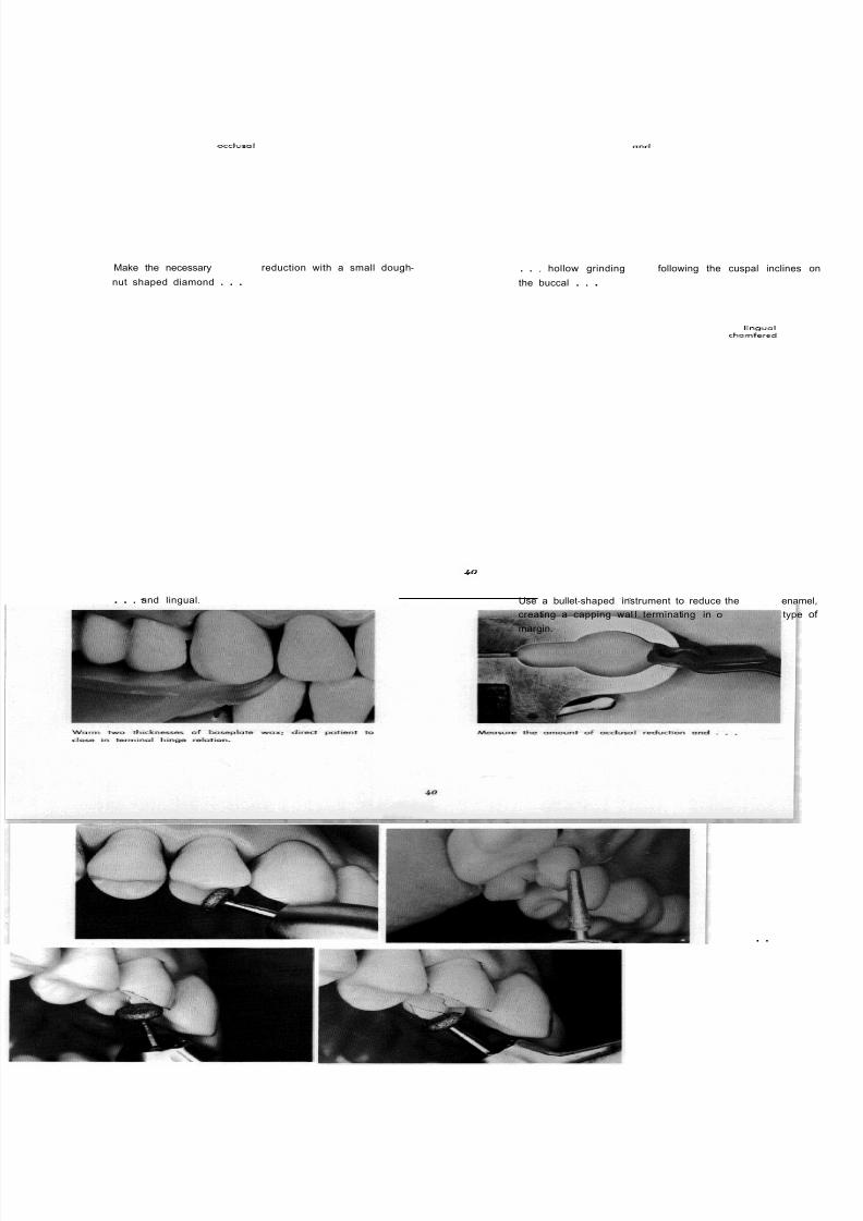
8/11/2019 An Atlas of Cast Gold Procedures
http://slidepdf.com/reader/full/an-atlas-of-cast-gold-procedures 42/270
Make the necessary occlusol reduction with a small dough-
nut shaped diamond . . .. . , hollow grinding and following the cuspal inclines
the buccal . . .
. . . and lingual. Use a bullet-shaped instrument to reduce the linguol enam
creating a capping wal l terminating in o chamfered type
margin.
. .

8/11/2019 An Atlas of Cast Gold Procedures
http://slidepdf.com/reader/full/an-atlas-of-cast-gold-procedures 43/270
. . . determine in millimeters. There should be a minimum
of one millimeter clearance.
Hollow ground buccal cusp and lingual cusp prepared for
"capping."
With a 699X long tapered fissure bur start proximal line
angle on the lingual . . .and on the buccal.
Position and angulation of bur for linguo-proximal line
angle . . .
and bucco-proximal line angle.
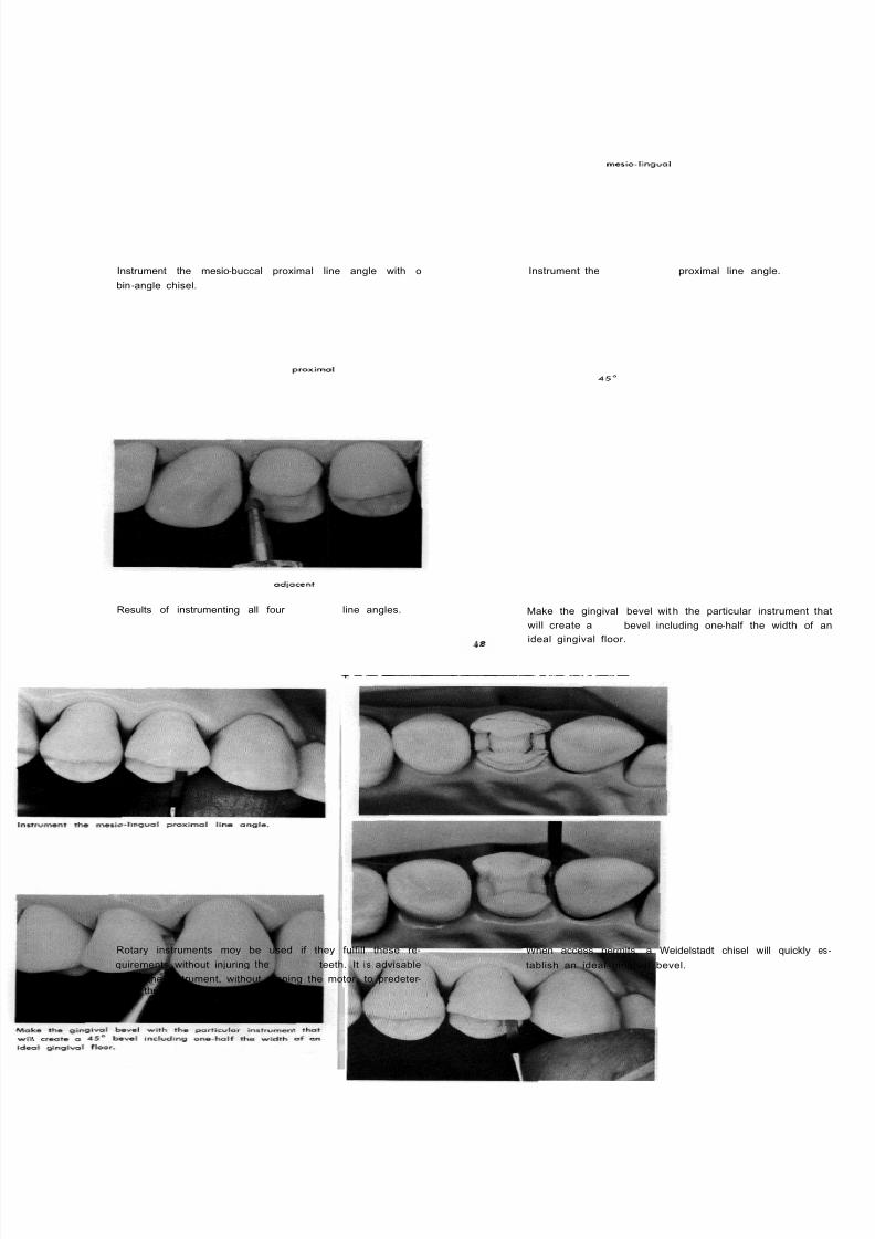
8/11/2019 An Atlas of Cast Gold Procedures
http://slidepdf.com/reader/full/an-atlas-of-cast-gold-procedures 44/270

8/11/2019 An Atlas of Cast Gold Procedures
http://slidepdf.com/reader/full/an-atlas-of-cast-gold-procedures 45/270
With the proper angulation of a Weidelstadt chisel, a straight
thrust from the buccal will produce an ideal gingivol bevel.
It will often be found that a sharp gingival margin trimmer
i s the instrument of choice in establishing an ideal gingival
bevel.
The proximal flares, which should connect with the gingival
bevel without an undercut in the gingival region, may be
established with a suitable hand instrument.
A bin -angle chisel establishing the mesio-lingual flare.
Dull the edge of a coarse Wet -0-Dry disc on a truing stone. This will help prevent cutting a V-shaped notch in the
gingival area.

8/11/2019 An Atlas of Cast Gold Procedures
http://slidepdf.com/reader/full/an-atlas-of-cast-gold-procedures 46/270
Determine the proper direction and angulation of the Wet-
0-Dry disc before running the motor.
Disto-lingual flare established by use of the Wet -0-Dry d
Re-shape a white polystone on the stone truer. Refine and finish the cavo-surface margin over the ling
cusp . . .
. . . and blend the sharp corners. Use the polystone to place a one-quarter to one-half
limeter finishing bevel, at right angles to the long axis
the prepared tooth, on the crest of the buccal cusp
44

8/11/2019 An Atlas of Cast Gold Procedures
http://slidepdf.com/reader/full/an-atlas-of-cast-gold-procedures 47/270
. . . and blend any sharp angles. Finished preparation, with internal . . ,
. . and external details. Finished preparation, with all requirements.
45
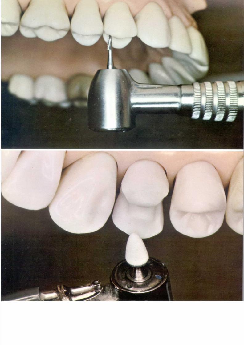
8/11/2019 An Atlas of Cast Gold Procedures
http://slidepdf.com/reader/full/an-atlas-of-cast-gold-procedures 48/270

8/11/2019 An Atlas of Cast Gold Procedures
http://slidepdf.com/reader/full/an-atlas-of-cast-gold-procedures 49/270
TOP PLATE
Ai r rotor used in M.O.D. onlay preparation.
BOTTOM PLATE
White polystone used to place finishing bevel on
buccal cusp of maxillary M.O.D. onlay preparation.
8/11/2019 An Atlas of Cast Gold Procedures
http://slidepdf.com/reader/full/an-atlas-of-cast-gold-procedures 50/270
CHAPTER
Tissue Management, Impression Technique Using Reversible
Agar Hydrocolloid and Completing
Temporary
Introduction
The use of reversible agar hydrocolloid is contin-
ually increasing in popularity since its introduction.
An inlay technique using hydrocollo id was reported
by Sears( ) as early as 1937. Although World War I I
temporari Iy removed these materials from the market,
their reappearance in 1945 stimulated a tremendous
amount of laboratory and clinical research, whichfurther perfected the techniques for their use. Research
has led to simplified and standardized procedures.
Clinical results and laboratory tests have removed any
doubt as to the accuracy of reversible hydrocolloid,
not only for prosthetic appliances, but also for the
reproduction of teeth and their preparations. However,
it must be pointed out that the success of the technique
depends upon proper control and attention to many
variables. It i s the purpose of this Atlas to present a
standardized technique which has produced consistent-
ly accurate results over a period of many years.
Confidence and the best results from any ma-terial i s obtained only when the operator has a
fundamental working knowledge of its phys ica l
properties. Reversible hydrocolloid i s composed princi-
pally of colloidal agar agar wi th water as the dispersing
medium. The material consists of a gel structure in
which water is held by capillary action. It can be
liquified and changed to a colloidal solution by heating
and then can be returned to the gel state by cooling.
Agar agar, which i s obtained from certain species of
sea weed, has a gelation temperature of approximately
102 degrees F., which i s compatible to mouth tempera-
ture. On the other hand, the alginate materials are
changed from colloidal solution to a gel by chemicalreaction and cannot be returned to a colloidal solution
by ordinary means. This type of hydrocolloid i s said
to be irreversible.
Because of the extreme accuracy of reversible
agar hydrocolloid, it has proved to be one of the
greatest aids in accomplishing a better health service.
The accuracy of master dies and working models made
I ) Sears, A.W., Hydrocolloid Impression Technique for Inlays
and Fixed Bridges Digest Dentistry XLI I I 1937, 2 3 0 2 3 4 .
Restoration
from hydrocolloid impressions permits the dentist to
delegate certain steps in laboratory procedures to
auxiliary personnel. This provides the operator with
more hours at the chair to render an increased service
for the patient.
Although this Atlas wi ll treat certain spec i f ic
techniques and materials used in restoring Teeth with
cast restorations, the primary objective i s to empha-
size fundamental principles which will be the basis
for the application of any technique or material. It
must be kept in mind that new and improved materials
and techniques will continue to be developed in the
future, all of which must be based upon a knowledge
of sound fundamentals.
The indirect hydrocolloid impression technique
offers the following advantages:
1 ) Accuracy of reproduction.
2) Comparative ease in reproducing inaccessible
and extensive preparations.
3) A more economical approach in fabricatingmultiple restorations.
4) Adaptability to procedures for f u l l m ou th
reconstruction.
5 ) I ts accuracy results in the saving of time
during finishing.
6) It permits us to study our failures on the stone
models. Here the operator may study many
conditions which would be difficul t to observe
in the mouth.
Procedures for Tissue Management
Reversible agar hydrocolloid properly used i s
extremely accurate. However, it must be remembered
that when it i s liquified it does not have sufficient
body to retract or displace interfering gingival tissue.
The cavity preparation must be clean and dry and a l l
margins exposed either by retracting or removing any
interfering tissue.
There are four general methods for managing
interfering tissues:
1) Surgery.
47
8/11/2019 An Atlas of Cast Gold Procedures
http://slidepdf.com/reader/full/an-atlas-of-cast-gold-procedures 51/270
2) A mild form of electric current. (dessicating
f uIg ura ting or coagu
Iat ing)
3) Packing tissues with a strand of cotton yarn
impregnated wi th a non-caustic type of
astringent and a hemostatic agent.
4) Retraction with rubber dam.
In a l l instances where the finish line or gingival
bevel of a preparation has been placed under the
protection of the free gingiva, a degree of abrasion
and injury results from instrumentation. The use of
3% hydrogen peroxide introduced into the gingival
crevice under pressure with a spray bottle i s the most
advantageous method for inhibiting hemorrhage and
preparing the tissue for retraction by additional
methods. The most beneficial effect of the hydrogen
peroxide treatment is obtained when the application
is continued over a period of two to three minutes.
The full astringent action and hemostatic effect is
accomplished only when the tissue adjacent to the
finish line of the preparation has turned white in color
due to the absorption of free oxygen. Another bene-f icial effect from the hydrogen peroxide treatment is
the elimination of a large percentage of pathogenic
bacteria in the area. Tissue tone and healing are
considerably improved post-operatively by this treat-
ment.
To properly examine the finished preparation and
to make an accurate impression, al l margins plus a
slight distance beyond must be visible. In many in-
stances it will be necessary to employ a combination
of methods for tissue management to accomplish this.
Some of the astringent agents such as zinc chloride are
caustic in nature and destroy tissue. At the present
time a recommended astringent agent i s 4% LevoEpinephrin Bi-tartrate with 9% potassium alum. This
preparation i s non-caustic in nature and can be pre-
pared by any pharmacist.
When the packing technique i s used either alone
or in conjunction with -surgery, or the use of some
form of electric current, three factors are involved: the
medicament used, time, and pressure.
When strands of cotton yarn* are used in con-
junction with an astringent agent for tissue retraction,
one of two methods may be employed. The yarn may
be dampened with the epinephrin solution before
carrying i t to place, or, i t may be tucked into posi-
tion under the gingival tissues while dry and then
moistened by applying the solution with cotton pliers.
Epinephrin should be used sparingly since the wick
action of the cotton strands carries the medication into
direct contact with the tissue. Caution must be exer -
cised in the use of epinephrin with patients having
* I f yarn other than a dental product is purchased, care must be
taken to obtain pure cotton yarn that does not contain sizing
or other type of nan-wett ing agent. Lil ly Cotton Yarn, Article
No 930, color 3( l ight cream] four strand, 125 yds. n length.
MFG by Lil ly Mills, Shelby. N. Carolina, U.S.A.
diabetes, hypertension or hyperthyroidism. Absorptio
directly into the blood stream may cause untowa
physiological reactions in these cases. While the me
cation and packing are usually left in place from thre
to five minutes, the tonicity of the tissue will, to
great extent, govern the time required to obtain co
plete action of the medication used. A longer time
necessary in the presence of inflammatory gingiv
tissue or where considerable retraction is necessa
to expose the margins of the preparation. If examintion indicates the presence of hyperplastic tissue or a
excessively deep gingival crevice, surgical correctio
is indicated. If such indicated surgical correction
instigated in conjunction with restorative procedure
the tissue management program is simplified a
excellent results in tissue healing can be obtaine
Although it i s necessary to obtain adequate tiss
retraction when using the softer impression materia
it must be recognized that excessive and prolong
retraction will result in permanent tissue damage.
When one of the forms of electric current is us
for the management of interfering tissues, the operatmust have a thorough knowledge of the principl
involved and the techniques employed. This is essent
if tissue destruction is to be prevented and the mo
desirable healing obtained. A spark-gap damped hi
frequency current produces desiccation, f b Igura ti
and coagulation (hemostasis). This type of current w
not produce a cutting action on tissue. Desiccation
accomplished by placing the needle into the tiss
while fulguration is produced by a spark-gap betwe
the needle and the tissue. Coagulation i s brought abo
by a bi-polar current with a two-pronged need
inserted into the tissue.
If surgery i s employed, preparatory to making a
impression, it is essential that the accepted principl
of sound periodontal surgical procedures be follow
to insure proper healing which w il l produce the desir
tissue morphology and architecture.
Whenever the rubber dam can be used for iso
tion and retraction of tissue to the required limits,
affords the most ideal conditions for making a
accurate indirect impression of the teeth and the
preparations. The problems of withdrawing the i
pression interposed by the presence of the rubber da
clamp are readily solved by blocking off the jaws an
bow of the clamp with soft wax.
Impression Technique Using
Reversible Agar Hydrocolloid
To obtain consistently accurate results with
versible hydrocolloid it is recommended that
standardized step-by-step procedure be closely fo
lowed. Any short cut or dev i at i o n from soun
principles increases the possibility of error.
8/11/2019 An Atlas of Cast Gold Procedures
http://slidepdf.com/reader/full/an-atlas-of-cast-gold-procedures 52/270
It must be recognized that the proper armamen-
tarium for preparing and conditioning the material i s
essential for obtaining consistent results. It i s desirable
to have a unit wi th three water baths thermostatically
controlled. One bath should be set at boiling tempera-
ture for liquefying the material. Another bath should
be held at 145-150 degrees F. and will serve as a
storage bath to keep the material in a workab le
condition a t a l l times. The third bath i s maintained a t
105-115 degrees F. This serves as a tempering medium.
It will be noted that these temperatures have a rough
leeway which is permissible, and can be regulated to
suit the operator. For example, if the tempering bath
i s set at 105 degrees F., it will only be necessary to
allow the hydrocolloid to temper a minimum of three
minutes before making the impression and the ma-
terial will be workable up to about five minutes.
However, if the tempering bath is set at 115 degrees
F., the minimum tempering time would be five min -
utes, and workable up to 10 minutes. These variations
do not violate any of the fundamentals involved and
are simply a convenience suited to the individual
opera tor.
The technique for using reversible hydrocolloid
i s based upon the capacity of the material to be
liquefied and placed in the mouth at temperatures
compatible to the tissues. Upon chilling, it must attain
a stiff gel state with sufficient elasticity to permit
removal from the mouth without distortion. To accom-
plish this, seven major steps in procedure are involved:
1) Liquefication by boiling
2) Storage of the material at a temperature which
3) Lowering the temperature of the tray material
in order that it may be placed in the mouth
without discomfort and to give the tray ma-
terial the desired degree of stiffness or body.
4) Injecting a quantity of warmer, more flu id
hydrocolloid into the details of the clean, dry
preparation.
5) Placing the impression tray in the mouth.
6) Adequate chil ling of the tray and material to
change the colloidal sol into its gel state.
7) Removal of the impression without distortion.
Several small syringes are required to inject andfill the preparation with warmer and more fluid
hydrocolloid. There are numerous types of trays avail-
able. Trays may also be fashioned from perforated
brass anddesigneld
to suit the case. All trays should
permit a bulk of material. Each tray must be blocked
at each end, if possible, with a hard wax stop, which
will rest on the teeth at either side of the prepared
tooth. (Dentsply set-up wax i s ideal for the wax stops.)
Where teeth are absent posterior to the preparation,
the wax stop is made longer on the anterior portion
will maintain the material in a colloidal state.
of the tray. This will permit a bearing on several teeth
anterior to the preparation. These wax stops or rests
should be luted to the tray and serve as a definite
place to seat the tray and prevent it from touching any
part of the prepared tooth or teeth. The finger pressure
used in seating and holding the tray in position should
always be in the center of the wax bearing area, to
insure stability while chilling.
After the wax stops have been placed in thetray, the stops are warmed slightly over the flame and
the tray i s placed in the mouth. When it is correctly
positioned, slight pressure is exerted to mark the cusps
of the teeth in the wax stops. Then with a sharp pencil,
a line i s marked on the anterior wax stop followed by
a corresponding pencil line on the tooth. This will give
a definite guide in seating the tray after it has been
filled with hydrocolloid.
In making the impression, the clean dry cavity
is filled by injecting hydrocolloid with the small
syringe using care not to trap air. The syringe is placed
in the deepest gingival area before injecting. An excessof material i s ejected over the tooth to prevent pre-
mature chilling. This is immediately covered with the
tray of tempered hydrocolloid. The tray i s quickly
seated and held steadily in position while the material
is chilled with cold water for a minimum of six
minutes. In seating the tray the cusps of the teeth
involved should only penetrate about three-fourths the
thickness of the wax stops. If the cusps of the teeth
touch any part of the tray, the impression may skid
and the resulting dies will be inaccurate. In cases of
deep extensions, or thin edges occurring in the im-
pression, it will b e found helpful to chill longer. The
conventional water -cooled tray chilling may be sup-
plemented with cold water from a syringe. It must
be remembered in chilling hydrocolloid, that the
material is a poor conductor, and that time is as
important a factor as the temperature of the water
used. The use of tap or ice water seems to make no
clinical difference, if the chilling time is adequate.
After thorough chilling, the tray i s removed with a
snap, using the index finger of both hands on the
center of the under edges of the tray, from the buccal
and lingual.
The impression is removed and examined. In
order to see detail, the free moisture should be gentlyblown from the impression. If the impression does
not definitely include a l l of the margins and a slight
excess beyond, it should be discarded. If acceptable,
it i s washed in cold running tap water to remove any
mucus or saliva. It is then placed in a 2% solution
of potassium sulfate. The impression should be stored
in this solution and the stone die should be run within
15 minutes always using a vacuumed mix of stone.*
Two good impressions are made for the master dies.
This provides insurance against the possibility of
*Bassett, R.W., Vander Heide, J.D. Smith, D.D. "Clinically
Oriented Tests Comparing Accuracy of Elastic Impression
Materials" Journal, Southern California State Dental
Association, Feb., 1969.
49
8/11/2019 An Atlas of Cast Gold Procedures
http://slidepdf.com/reader/full/an-atlas-of-cast-gold-procedures 53/270
reappointing the patient to repeat the operation if a
die i s iniured during laboratory procedures. Some of
the failures in the use of hydrocolloid may be
attributed to the following:
1) Interfering gingival tissue.
2) Inadequate chilling.
3) Distortion upon removal.
Working models may be made from either full
mouth or sectional double-bite hydrocolloid impres-
sions. When one, t w o or t hr ee preparations areinvolved and there is a remaining posterior tooth to
function as a stop, experience has shown that a
double-bite impression using the Coe Check-Bite Tray
will give uniformly satisfactory results. When multiple
adjacent preparations have been made and there is no
remaining posterior stop, full mouth models are
necessary. The orientation of f u I I mouth working
models requires special attention to a check bite tech-
ARMAMENTARIUM FOR TISSUE
nique for obtaining an accurate registration of th
hinge occlusion position.
A half stick or full stick of inlay wax is softene
in the tempering bath of the hydrocolloid conditioni
unit. It is then flamed in the Bunsen burner, folded
half and molded between thumb and finger to t
approximate size of the preparation area. This pa
of wax is again flamed and placed over the prepar
tion area. With the thumb and finger against the chi
the patient i s instructed to "quickly close". Since twax covers only the prepared teeth, observation
the relationship of the opposing teeth on the oppos
side of the arch and the presence of faceted areas w
indicate if an accurate hinge occlusion has be
registered. After sufficient cooling the wax registr
tion is laid aside until the impressions have bee
poured and the models prepared for mounting on
hinge type articulator.
MANAGEMENT, HYDROCOLLOID
IMPRESSIONS AND TEMPORIZING
TISSUE MANAGEMENT
SCALER, FINE PUMICE, END BRUSH, RUBBER CUP,
SPRAY BOTTLE WITH 3% HYDROGEN PEROXIDE
COTTON PLIERS
4 LEVO-EPINEPHRINE 81-TARTRATE WITH 9 7 AL UM
FOUR STRAND COTTON YARN
PACKING INSTRUMENT
COTTON ROLLS
IMPRESSIONS
PERFORATED TRAY
DENTSPLY SET-UP WA X
7 WAX SPATULA
HYDROCOLLOID CONDITIONER AND ACCESSORIES
BEAVER TAIL BURNISHER
WATER SYRINGE
TIMER
2 POTASSIUM SULFATE
COE CHECK-BITE TRAY
TEMPORIZING
VASELINE
COLD CURE PLASTIC
ZINC-OXIDE EUGENOL EMENl
50

8/11/2019 An Atlas of Cast Gold Procedures
http://slidepdf.com/reader/full/an-atlas-of-cast-gold-procedures 54/270
PROCEDURES FOR TISSUE MANAGEMENT, IMPRESSION TECHNIQUE USING
REVERSIBLE HYDROCOLLOID AND COMPLETING TEMPORARY RESTORATION
Clean the prepared tooth, and adjacent teeth with suitable
scaler, rubber cup and end brush . . .
MOD onlay preporation in lava testing die, oriented in
typodont with removable plastic shim. [Refer to Chapter 1 3 ) .
. . . and spray under the gingival tissues until the crest
of the gingiva becomes blanched. This procedure wi l l mini -
mize the problems of retraction.
. . . using flour of pumice wet
C
After tooth ond its preparation hove been cleaned, use 3
hydrogen peroxide in spray bottle . . .
Cotton pliers, 4Levo-epinephrin bi -tartrate with alum,
four strand cotton yarn, scissors and packing instrument,
mode from Hollenback 3 waxing instrument.
51
8/11/2019 An Atlas of Cast Gold Procedures
http://slidepdf.com/reader/full/an-atlas-of-cast-gold-procedures 55/270

8/11/2019 An Atlas of Cast Gold Procedures
http://slidepdf.com/reader/full/an-atlas-of-cast-gold-procedures 56/270
. . . and remove the interproximal tissue. Debridement and partial hemorrhage control may be accam-
plished by spraying fresh 3 hydrogen peroxide on ond
under the tissue. Continue this procedure unt il the tissues
turn white in color.
Use a rubber cup with fine wet pumice to clean the tooth
and i ts preparation.
With a hot spatula, seal wax stop to the tray.
Warm bath tray and Dentsply set-up wax. Place a wax stop
at end of tray, using edge of tray as knife to cut the wax.
Wherever possible use wax stops a t each end of tray.
53
8/11/2019 An Atlas of Cast Gold Procedures
http://slidepdf.com/reader/full/an-atlas-of-cast-gold-procedures 57/270
Try tray in mouth and use a pencil to make identification
mark on wax stop and tooth.
Place nozzle of hydrocolloid tube in base of tray and fill
with hydrocolloid. Make sure the impression material i s
forced through the perforations of the troy.
When no posterior teeth are present, a wax stop three te
wide i s used at anterior part of troy.
Hydrocolloid Conditioner:
A. Liquefying bath
B. Tempering both
C. Storage bath
Place the tray filled with hydrocolloid in the tempering bath. Set the timer for 5 minutes.
54

8/11/2019 An Atlas of Cast Gold Procedures
http://slidepdf.com/reader/full/an-atlas-of-cast-gold-procedures 58/270
Tube of hydrocolloid, stick of hydrocolloid and small syringes To fil l small syringe, place stick of hydrocol loid in syringe
even with end of borrel. Insert plunger and squeeze unt il
all air has been removed from syringe.
When tray material has been properly tempered, remove
one-inch pieces of two strand cotton yarn . . .and retuck single strand under free gingiva.
Use a camel hair brush to lubricate the single strand of
cotton yarn with Microfilm. Use air syringe to blow of f any
excess Microfilm.
Start at the deepest part of the preparation and eject the
warmer and more fluid hydrocolloid from the small syringe.
55

8/11/2019 An Atlas of Cast Gold Procedures
http://slidepdf.com/reader/full/an-atlas-of-cast-gold-procedures 59/270
Eject a bulk of hydroiolloid over the tooth to prevent pre-
mature chilling.
Remove tray with tempered hydrocolloid from tempering b
and wipe surface with cotton roll.
Immediately seat the troy, pressing only ’/?
way through
the thickness of the wax stops. Hold tray firmly in place
with the finger in the center of the wax bearing area.
In deep preparations, use o syringe of cold water for au
iary chilling . . .
. and chi ll for a minimum of six minutes. Before removing the impression, use a beaver tai l
nisher . . .
56

8/11/2019 An Atlas of Cast Gold Procedures
http://slidepdf.com/reader/full/an-atlas-of-cast-gold-procedures 60/270

8/11/2019 An Atlas of Cast Gold Procedures
http://slidepdf.com/reader/full/an-atlas-of-cast-gold-procedures 61/270
Try in alginate impression before molding temporary cold
cure plastic restoration.
Mix cold cure plastic and fill recess of prepared tooth.
Remove temporary plastic restoration from tooth and place
in hot water to accelerate hardening.
App ly a fi lm of Vaseline over the soft tissues.
Seat
alginate impression, guided by identification ma
Remove impression before plastic has completely harden
Rehearse Coe check-bite troy in mouth by instructing pa
to "open" and "quickly close."
58
8/11/2019 An Atlas of Cast Gold Procedures
http://slidepdf.com/reader/full/an-atlas-of-cast-gold-procedures 62/270
Observe cuspal interdigitation on opposite side of arch
Fi l l one side of Coe check-bite tray with hydrocolloid which
has been tempered for 5 minutes . . .
Start at the deepest part of the preparation and eject hydro-
colloid from the small syringe . . .
Place parchment in tray and secure in place with small
piece of Kerr's red utility wax.
. . . and then fill other side. The tempered material will
have enough "body" to allow bath sides o f double tray
to be filled.
. . .and eject a bulk over the tooth to prevent premature
chilling.
59

8/11/2019 An Atlas of Cast Gold Procedures
http://slidepdf.com/reader/full/an-atlas-of-cast-gold-procedures 63/270
Place Coe check-bite tray in mouth ond instruct patient to
"quickly close."
Chill for a minimum of six minutes.
Observe interdigitation of cusps on opposite side of arch
be sure patient i s closing in terminal hinge relationsh
Instruct patient to hold handle of the coe check-
impression tray while exerting firm pressure between
maxillary and mandibular teeth.
During the six-minute period the impression i s chill
contour and palish the temporary restoration.
Before removing impression, examine opposite side of arch
to be sure patien t has held teeth tight ly together in terminal
hinge relationship.
60
Thoroughly wash impression in topwater.

8/11/2019 An Atlas of Cast Gold Procedures
http://slidepdf.com/reader/full/an-atlas-of-cast-gold-procedures 64/270
Cut extension of hydrocolloid even with edge of troy. Place impression in 2% potassium sulfate solution or humidor
with 100 relative humidity.
Fit temporary plastic restoration into prepared tooth and
check occlusion with articulating paper.
Use zinc oxide eugenol to cement the temporary plastic
restoration.
61
Carefully adjust occlusion with mounted stone.

8/11/2019 An Atlas of Cast Gold Procedures
http://slidepdf.com/reader/full/an-atlas-of-cast-gold-procedures 65/270

8/11/2019 An Atlas of Cast Gold Procedures
http://slidepdf.com/reader/full/an-atlas-of-cast-gold-procedures 66/270
TOP PLATE
Filling oe Check-Bite tray wit h tempered hydrocolloid.
BOTTOM PLATE
Preparation side of Coe Check-Bite impression.

8/11/2019 An Atlas of Cast Gold Procedures
http://slidepdf.com/reader/full/an-atlas-of-cast-gold-procedures 67/270

8/11/2019 An Atlas of Cast Gold Procedures
http://slidepdf.com/reader/full/an-atlas-of-cast-gold-procedures 68/270
The basic physical nature of wax is such that
distortion of the pattern is a continual hazard. Not
only does wax have one of the highest coefficients
of thermal expansion of any of the materials used in
dentistry, but i t al so possesses a relatively low
softening temperature where stress release or plastic
flow may occur. Stresses are easily induced in forming
any pattern; in fact, to form a completely stress-free
wax pattern would appear to be improbable. With
the knowledge of the physical characteristics of theinlay wax, it becomes the task of the operator to
minimize the stress within the pattern, so far as
possible, by the application of manipulative pro-
cedures which permit proper temperature and stress
control of the wax. Regardless of the technique em-
ployed, a l l details should be followed carefully.
Inlay pattern waxes have been described as soft,
medium and hard, depending upon the temperatures
required to bring them to the plastic or workable
stage. These temperatures range from 104 to 122
degrees F. (40 to 50 degrees C. . The medium and
harder waxes, although somewhat more diff icu lt to
manipulate than the softer waxes, are safer to use
because they are less subject to manipulative distortion.
The softer waxes which become plastic or workable
a t a lower temperature range are particularly valuable
for making final marginal corrections in either direct
or indirect techniques.
The specifications for acceptable inlay waxes are
set forth by the U.S. Bureau of Standards, and the
Research Committee of theA.D.A.*
A number of formulas for pattern wax have been
published. Some of these are quite complex. The
essential ingredients of an acceptable wax are con-sidered to be 40 to 60 percent paraffin with gum
dammar, carnauba or candelilla and the addition of
a coloring agent. The components of a successful wax
should be so blended that it may be softened by heat
at a temperature slightly above that of the tooth so
that it can be forced into the prepared cavity to
reproduce every minute detail. On the other hand the
wax should be rigid when cooled to the temperature
of the mouth so that the pattern may be removed
from the preparation without distortion. There are
many acceptable pattern waxes on the market today
which will give excellent results if intelligently
manipulated. Many investigators recognize what maybe called the "memory of wax." Wax when heated
and allowed to cool will tend to assume its previous
shape. Recognizing this fact, i t is advisable to liquefy
the wax thus disassociating i t s previous molecular
form. The wax in this stateday
be applied to the
cavity preparation. It wil l assume a new molecular
are certain precautions that should be taken to preven
distortion which are listed as follows:
1 Minimize any unnecessary handling of th
wax pattern.
2) Avoid any sudden changes in temperature
3) it will be found beneficial to use a soft deawax. Melt this added wax into and over th
margins, before making the final marginarefinement.
4) After final refinement, remove the patter
from the master die to prevent adherenc
to the surface of the stone.
5) Care should be taken to avoid distortion o
the pattern in its removal from the prepare
tooth or die.
6) Invest the pattern immediately after it i s re
moyed from the prepared tooth or die.
Fundamental Requirements of an Ideal Wax Patter
1) Reproduction of internal details of the prepara
tion and accurate marginal adaptation.
2) Reproduction of g en er al tooth fo rm an
contours.
3
To establish ideal embrasure contour, margina
ridge relationship, shape, size and position o
contact areas.
4) To establish functional occlusal anatomy.
An accurate reproduction of the internaldztail
of the preparation is essential in obtaining maximum
retention for the casting. If the cavity preparation em
bodies al l requirements for resistance and retentio
form, accurate reproduction of these features in th
wax pattern will eliminate the possibility of dislodge
ment of the cemented casting during function. A
efficient technique for a final "melt-in" of al l surround
ing margins of the wax pattern i s essential to obtai
an accurate fit of the margins of the casting.
In order for the finished restoration to meet idea
criteria, it is necessary that the following features firsbe developed in the wax pattern: proper contour
embrasure and marginal ridge rqlationships; idea
shape, size and position of contact areas; and functiona
occlusal anatomy.
It i s recommended that Chapter 14 titled "TOOT
*American Dental Arsoclotfon Specification N ~ . : Specification
for dental wax pattern.
inlay casting wax.
6

8/11/2019 An Atlas of Cast Gold Procedures
http://slidepdf.com/reader/full/an-atlas-of-cast-gold-procedures 69/270
ARMAMENTARIUM FOR MAKING THE STONE DIE AND WAX PATTERN
STONE DIE
7 WAX SPATULA
ROOM TEMPERATURE WATER
PLASTIC CC. GRADUATE
ALGINATE MEASURING CUP
VACUUM PUMP AND ACCESSORIES
VACUUM MIXING BOWL
VIBRATOR
HUMIDOR
’ 4”
ARBOR BAND
BARD PARKER KNIFE # 5 HANDLE; #11 BLADE
‘e” JOE-DANDY OR DIAMOND DISC
WAXING
TALCUM POWDER
CARBON TETRACHLORIDE
SLIK-DIE LUBRICANT
WAXING PLIERS
THOMPSON WAX CARVER
KERR‘S WAX-UP WAX
HARD INLAY WAX
RED COUNTER WAX
FINE SOFT SILK
CAMEL HAIR BRUSHES
3 EXPLORER
SEWING THREAD
18 GAUGE HOLLOW SPRUE
22 K -
29 GAUGE GOLD WIRE
CRATER FORMER
CASTING RING
ASBESTOS LINER
65

8/11/2019 An Atlas of Cast Gold Procedures
http://slidepdf.com/reader/full/an-atlas-of-cast-gold-procedures 70/270
PROCEDURES FOR MAKING THE STONE DIE AND WA X PATTERN
Wax spatula, room temperature water,12c.c.
plastic graduate
and 50 grams of Vel -Mix stone.
The stone may be weighed on a diet scale.
Englehardt vacuum mixing bawl and vibrator.
Mix the stone using vacuum and heavy vibration, for 75
seconds.
Release vacuum seal and continue heavy vibration until
air has been removed from mix.
66
Add 12 c.c . o f water to 50 grams of Vel -Mi x s tone.

8/11/2019 An Atlas of Cast Gold Procedures
http://slidepdf.com/reader/full/an-atlas-of-cast-gold-procedures 71/270
Remove impression from potassium sulfate bath and blow
off excess moisture without desiccating impression.
App ly a small amoun t of stone on flange adjacent to recess
of prepared tooth.
Add small amounts of stone from the same star ting poi ni
and with mild vibration . . .
slowly f i l l recess of prepared tooth.
Add balance of stone to obtain proper length of finished die. Place filled impression in sealed plastic container with wet
cotton rolls which will serve as humidor.
67

8/11/2019 An Atlas of Cast Gold Procedures
http://slidepdf.com/reader/full/an-atlas-of-cast-gold-procedures 72/270
Remove Coe Check-Bite impression from potassium sulfate
bath. Blow off excess moisture without desiccating impression.
Using mild vibration, carefully fill with stone the side of
check-bite impression which has the prepared tooth.
i a c e
in humidor with the two master dieimpresslons.
Al lo w
the stone to harden for 45 minutes . . .. . . and then fill the opposite half of check -bite impress
Both sides of check-bite impression have been filled with
stone ready to be mounted on articulator.
68
Before separating, mount check-bite models an Steph
"Model D" Articulato r.

8/11/2019 An Atlas of Cast Gold Procedures
http://slidepdf.com/reader/full/an-atlas-of-cast-gold-procedures 73/270
Separate stone model from one of the master die impressions.
Partially trimmed master die models
Use -inch arbor band to start taper of root portion of die.
Remove bulk of stone with the model trimmer. After grinding
i s completed, briefl y wash stone, an d dry with air an d
examine for any remaining grindings.
Use the model trimmer for further trimming. Keep walls of
root portion of die parallel to each other.
The Bard Parker knife, 5 handle, # 1 1 blade i s usedto
69
8/11/2019 An Atlas of Cast Gold Procedures
http://slidepdf.com/reader/full/an-atlas-of-cast-gold-procedures 74/270
. . . undermine lip of stone which i s close to margins of
preparation.
With the Bard Parker knife, flip away undermined sto
which i s close to margins of preparation.
Use the Bard Parker 1 1 blade to taper root portion of
master die.
Make finished master die 3/4 inch long and tapered from
extent of the impression. Remove any interfering bulk of stone
which might interfere with waxing procedures.
70
Tapered master die and untrimmed master die model
To separate adjacent dies, draw a line from the center of
interproximal space on both the buccal and lingual surfac
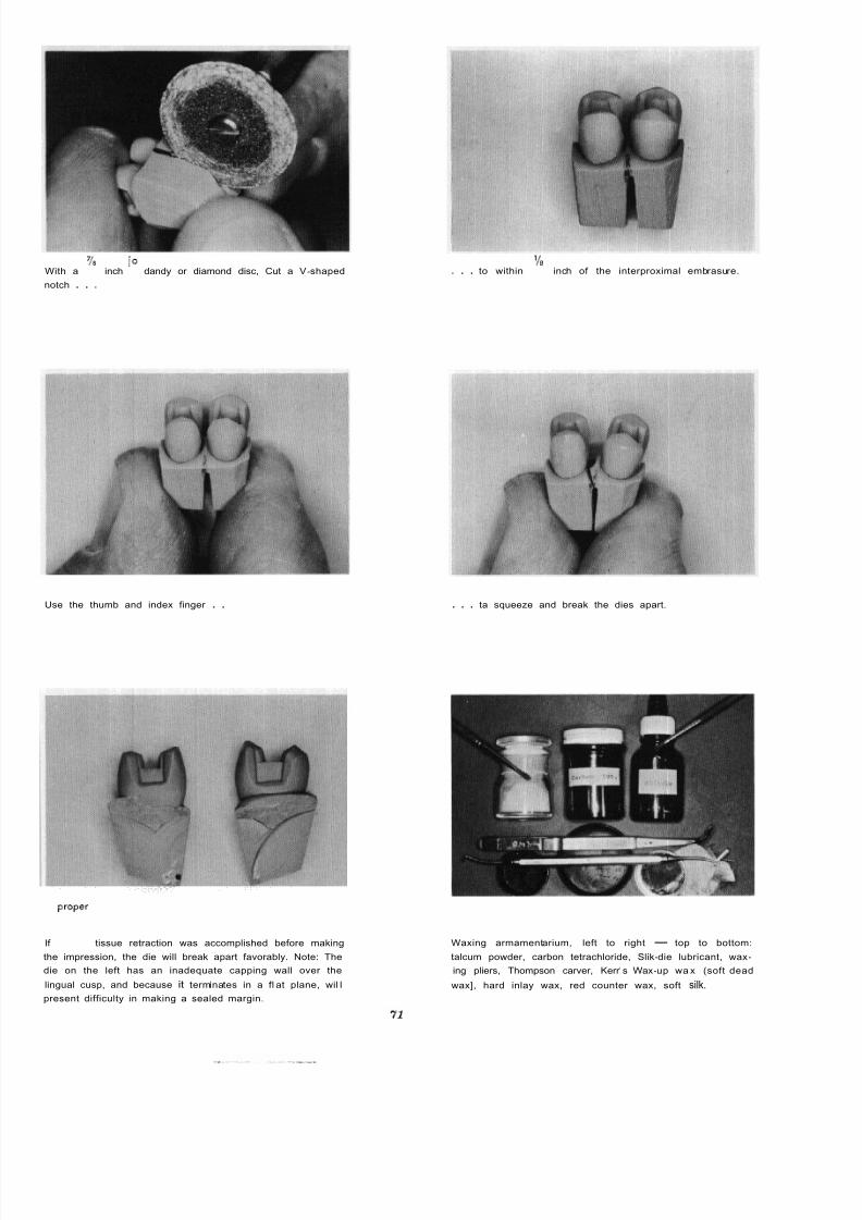
8/11/2019 An Atlas of Cast Gold Procedures
http://slidepdf.com/reader/full/an-atlas-of-cast-gold-procedures 75/270
With a
notch . . .
inch o dandy or diamond disc, Cut a V -shaped
Use the thumb and index finger . .
Ifproper
tissue retraction was accomplished before making
the impression, the die will break apart favorably. Note: The
die on the left has an inadequate capping wall over the
lingual cusp, and because it terminates in a fl at plane, wil l
present difficulty in making a sealed margin.
. . . to within inch of the interproximal embrasure.
. . . ta squeeze and break the dies apart.
Waxing armamentarium, left to right - top to bottom:
talcum powder, carbon tetrachloride, Slik -die lubricant, wax -
ing pliers, Thompson carver, Kerr's Wax -up wa x (soft dead
wax], hard inlay wax, red counter wax, soft silk.
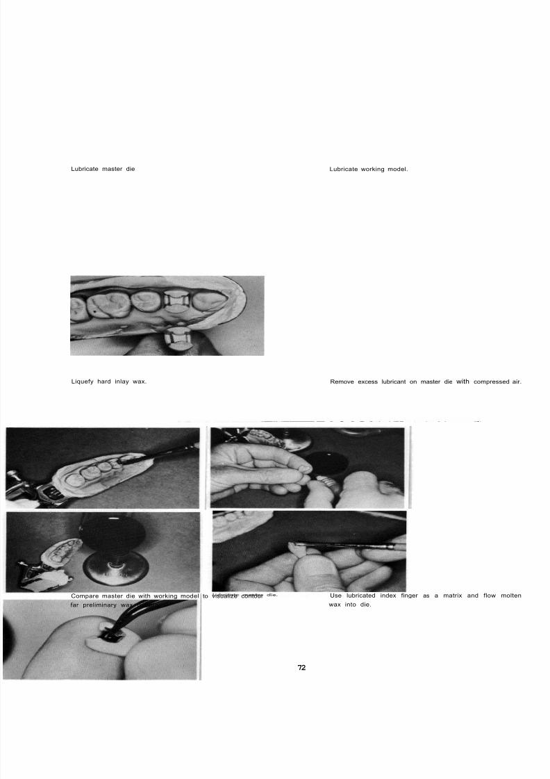
8/11/2019 An Atlas of Cast Gold Procedures
http://slidepdf.com/reader/full/an-atlas-of-cast-gold-procedures 76/270
Lubricate master die Lubricate working model.
Liquefy hard inlay wax. Remove excess lubricant on master die with compressed a
Compare master die with working model to visualize contour
far preliminary wax pattern.
72
Use lubricated index finger as a matrix and flow molt
wax into die.

8/11/2019 An Atlas of Cast Gold Procedures
http://slidepdf.com/reader/full/an-atlas-of-cast-gold-procedures 77/270
Pick up liquefied wox with waxing pliers and continue
flow-on without interruption.
Flow on wax to appropriate contour.
Turn die around . . . . . . and
carry moltenwax
into portion of pattern previously
established.
Continue to add molten wax . . . . . . and build to general contour.
73

8/11/2019 An Atlas of Cast Gold Procedures
http://slidepdf.com/reader/full/an-atlas-of-cast-gold-procedures 78/270

8/11/2019 An Atlas of Cast Gold Procedures
http://slidepdf.com/reader/full/an-atlas-of-cast-gold-procedures 79/270

8/11/2019 An Atlas of Cast Gold Procedures
http://slidepdf.com/reader/full/an-atlas-of-cast-gold-procedures 80/270
Use a sharp explorer to contour the buccal and lingual em -
brasures. This procedure will create a small saucer -shaped
concavity denoting the position of the contact area.
Occlusion may be established by the fallowing procedure
Use a camel hair brush to apply talcum powder.
Gently close the articulator to mark the premature contacts
of occlusion . . .. and carve away the interfering wax
Aga in dust wi th talcum powder , , , . . . gently close the articulator to mark the premature c
tacts of occlusion.
7’6

8/11/2019 An Atlas of Cast Gold Procedures
http://slidepdf.com/reader/full/an-atlas-of-cast-gold-procedures 81/270
Where occlusion requires that the pattern be built up, odd
wax with the waxing pliers.
...
Using the working models, establish the occlusion, general
contour, embrasure contour, position, shape and size of con-
tact areas.
Establish the contacts of terminal hinge occlusion in the
direction of the long axis of the tooth
chloride . .
. . . and re-lubricate with Slik-die.
77
The saucer -shaped concavity denotes position of contact area.

8/11/2019 An Atlas of Cast Gold Procedures
http://slidepdf.com/reader/full/an-atlas-of-cast-gold-procedures 82/270
Use the waxing pliers to carry Kerr's Wax -up wax to
pattern . . .
Use the waxing pliers tocarry
Kerr's Wax-up wax (soft dead
wax), and melt into and over each margin to a depth of
one millimeter.
The pattern i s ready for final marginal refinement.
78
. . . and fill the concave contact area. This will insure
plus contact area in the casting.
Fi l l the slight depression created between the contact ar
and the margins.
Use the warmed blade end of the Thompson carver, i n
rotary motion and burnish and iron the wax. Start this ir
ing procedure in the center of the wax and continue out a
over each margin to establish full rounded contour.
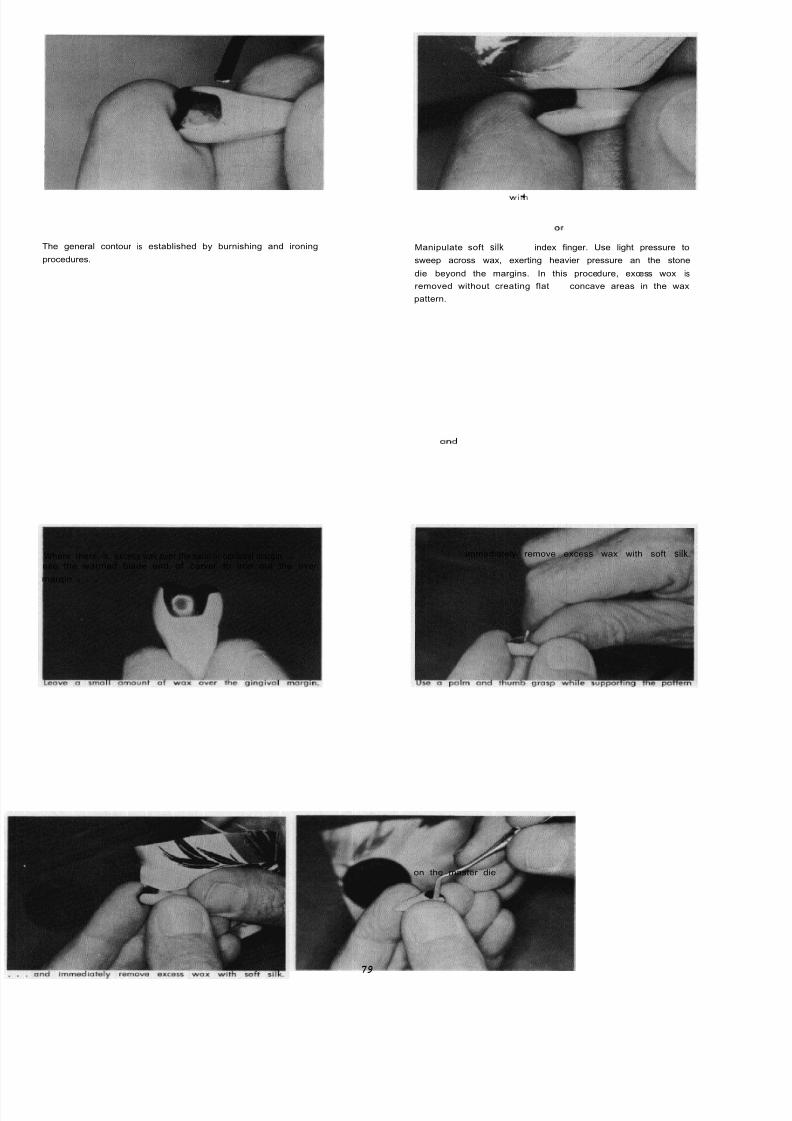
8/11/2019 An Atlas of Cast Gold Procedures
http://slidepdf.com/reader/full/an-atlas-of-cast-gold-procedures 83/270
The general contour is established by burnishing and ironing
procedures.
Manipulate soft silk with
index finger. Use light pressure to
sweep across wax, exerting heavier pressure an the stone
die beyond the margins. In this procedure, excess wox is
removed without creating flator
concave areas in the wax
pattern.
use the warmed blade end of carver to iron out the over
margin . . .
and
immediately remove excess wax with soft silk.
on the master die
79
waxWhere there is excess wax over the axial or occlusal margin,

8/11/2019 An Atlas of Cast Gold Procedures
http://slidepdf.com/reader/full/an-atlas-of-cast-gold-procedures 84/270
Establish a positive finger rest and perform a trial movement
of the instrument prior to actually cutting the wax.
Now use the warmed claw end of the instrument to clip off
the excess wax leaving m.m. gingival overlap. This proce
dure may have to be repeated several times to achieve the
desired result.
Accomplish a "trial free up" by slightly releasing pattern
from die.
Turn the die so that the gingival morgin is parallel with the
eyes.
Look under the margin ond slowly reseat pattern on the die.
This procedure will permit the operator to determine the
amount of gingival excess and if this excess wax is con-
tinuous from gingival angle to angle. Also carefully examine
o l l margins of pattern by paralleling each margin with the
eyes and looking under each margin separately. It should
be emphasized that each M.O.D. onlay pattern has eight
margins.
80
Make a V-shaped staple from 22K 29 -gauge gold wire
Bend the ends of the wire in the shape of a tiny foot. Warm
wire and ottoch to marginal ridges with the V over th
center of pattern.

8/11/2019 An Atlas of Cast Gold Procedures
http://slidepdf.com/reader/full/an-atlas-of-cast-gold-procedures 85/270
Add a drop of dead wox on the bulk iest par t of the patte rn
near the marginal ridge.
Lay pattern on paper towel and attach an 18 -gauge hollow
sprue to the drop of wax at an angle so that all of the
pattern i s ahead of the sprue. Many patterns may be safely
removed by the sprue. Place a drop of dead wax on the
pattern before attaching the sprue.
Increase diameter of sprue by addition of red counter wax.
Make diameter of sprue equalto
thickest part of pattern and
limit i t s length to ’/, inch.
Use a piece of sewing thread through the V -shaped staple
to remove the pattern in its most favorable line of shed.
Use notched pliers to mount pattern on crater former.
Place asbestos liner in casting ring. Make liner 1 /16 inch
short of ends of ring and be certain the remainder of ring
i s covered with the linerwithout
any appreciable overlapping.
Wet the asbestos liner and attach the casting ring to the
crater former.
81

8/11/2019 An Atlas of Cast Gold Procedures
http://slidepdf.com/reader/full/an-atlas-of-cast-gold-procedures 86/270

8/11/2019 An Atlas of Cast Gold Procedures
http://slidepdf.com/reader/full/an-atlas-of-cast-gold-procedures 87/270
TOP PLATE
Comparing master die with articulated working model
before waxing.
BOTTOM PLATE
Silk i s used to remove excess wax from margins of
stone die.
8/11/2019 An Atlas of Cast Gold Procedures
http://slidepdf.com/reader/full/an-atlas-of-cast-gold-procedures 88/270
CHAPTER
Controlled Investing and Casting Procedures
Introduction The quantity of gold used in making the casting is a
factor both in forcing the gases out of the mold and
To be successful, any inlay casting technique must
produce accurately fi tt ing castings. As in any other
driving the molten gold into al l details of the mold
with sufficient force.
f ield of dental science, there are a number of tech-
niques which will produce satisfactory results. It is the
objective of this Atlas to stress the fundamentals in-
volved which must be applied to any technique if it
is to produce consistant results. A technique for in -
vesting and casting is a mechanical procedure which
with ordinary care is not difficult to execute. It must
be emphasized, however, that the casting can be no
better than the wax pattern, regardless of the tech-
nique used. Inlay casting is not an exact science. Even
though great advances have been added, there are
still certain factors common to a l l inlay techniques
that are not completely understood and controlled.
With the present knowledge of the properties of the
materials used and the effect of variations in manipula-
tive procedures, the operator should be able to make
the necessary adjustments in his technique to correct
errors that will be encountered from time to time.
If consistently satisfactory results are to be
obtained, a standardized technique must be adopted
which w il l meet the needs of the operator in his
particular surroundings, and must become routine
office procedure. With standardized step by step pro-cedure it will be easier to detect and correct errors
that may occasionally creep into the technique.
Principles of Spruing
The importance of adapting the sprue to the
wax pattern is not generally recognized. Failure to
apply a few simple fundamental principles to the
procedure for spruing frequently results in faulty
castings. A very common error is the use of too long
and thin a sprue. This often results in so-called "shrink
spot" porosity in the region of the attachment of the
sprue to the casting. This may be eliminated by
employing a sprue of larger diameter and no morethan
Yi
in length. As a general guide, it is recom-
mended that the diameter of the sprue be equivalent
The sprue should always be attached to the
thickest part of the pattern and at the proper angle to
permit the go ld to enter the mold in the most favorable
direction. Caution should be used to minimize the
degree of heat introduced in attaching the sprue to
the pattern. This can be accomplished best by em-
ploying either a hollow metal or wax type sprue.
When a metal type sprue i s used, i t should be of
small diameter to limit the amount of heat necessary
for its initial attachment. It may then be built up tothe proper diameter by adding small increments of low
fusing wax. It i s also advantageous to add a small drop
of wax in the area of attachment before placing the
sprue.
The size and shape of the crucible employed will
depend upon the method of casting used. A deep,
steep walled crucible is most satisfactory for cen-
trifugal casting since it will concentrate the gold over
the sprue hole and prevent spilling of the gold. When
pressure or vacuum casting is used and the gold is
melted directly in the investment crucible, a shallower
crucible former with a flatter bottom will provideeasier access for the flame to reach and melt the gold.
Just before investing, the wax pattern should be
carefully examined for cleanliness. Where the pattern
has been made by the direct technique, any blood or
saliva may be quickly and thoroughly removed by
spraying its surfaces with hydrogen peroxide from
the spray bottle. Then rinse in room temperature water
and dry with air. When the wax pattern has been
fabricated on a stone die which has been lubricated
with microfilm or slik-die, it wi ll not be necessary to
wash the pattern or use a wetting agent. It should
be pointed out however, that an excessive amount of
lubricant on the die will prevent an accurate repro-
duction of the details of the preparation.
to the thickest portion of the wax pattern. When a
short sprue of correct diameter is used, the buttonCasting Investments
serves the purpose of a reservoir. Under these con-
ditions the gold in the mold will solidify first and
the sprue will remain molten to feed additional metal
to the casting until it has solidified. It should be
An investment can be described as a ceramic
material which is suitable for forming a mould into
which a metal or alloy may be appropriately cast.
pointed out that the size of the button also plays an
important part in obtaining a sharp, dense casting.
In general the investment is a mixture of three
distinct types of materials.
83
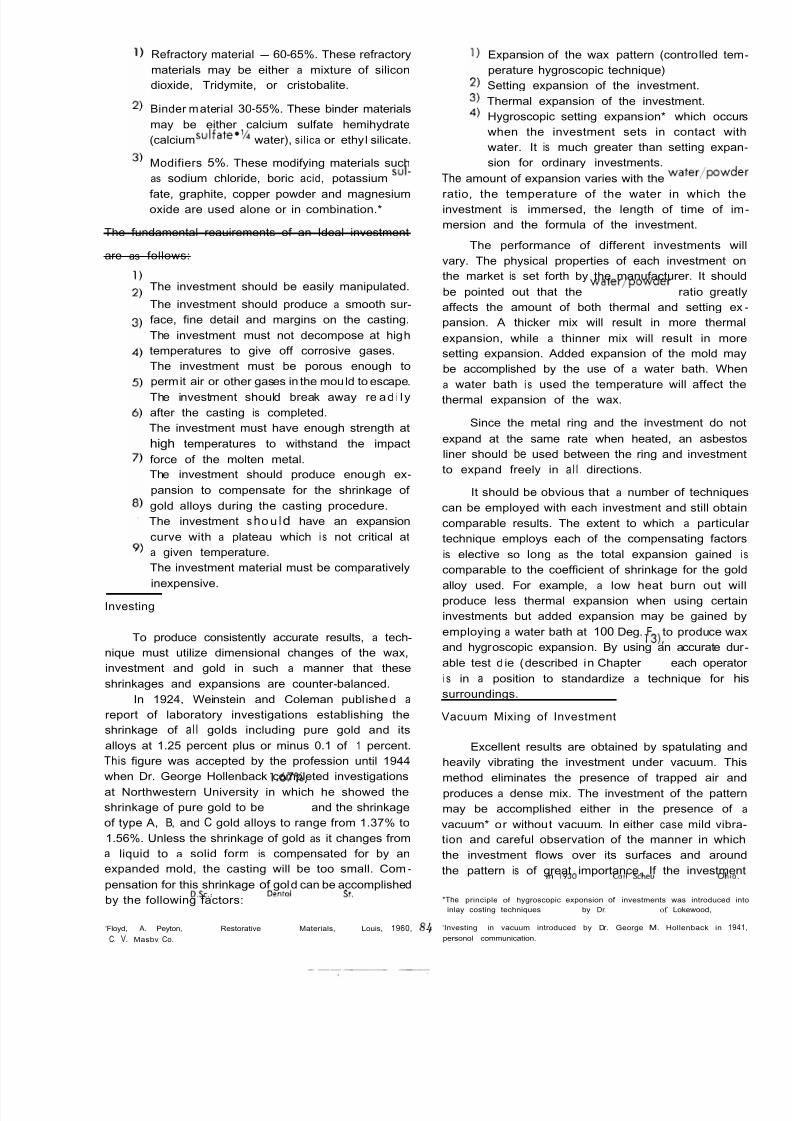
8/11/2019 An Atlas of Cast Gold Procedures
http://slidepdf.com/reader/full/an-atlas-of-cast-gold-procedures 89/270
Refractory material - 60-65%. These refractory
materials may be either a mixture of silicon
dioxide, Tridymite, or cristobalite.
Binder material 30-55%. These binder materials
may be either calcium sulfate hemihydrate
(calciumsulfate*’/i water), sil ica or ethyl silicate.
Modifiers 5%. These modifying materials such
as sodium chloride, boric acid, potassium SU I
fate, graphite, copper powder and magnesiumoxide are used alone or in combination.*
The fundamental reauirements of an Ideal investment
are as follows:
The investment should be easily manipulated.
The investment should produce a smooth sur -
face, fine detail and margins on the casting.
The investment must not decompose at high
temperatures to give off corrosive gases.
The investment must be porous enough to
permit air or other gases in the mould to escape.
The investment should break away re ad i l y
after the casting is completed.
The investment must have enough strength at
high temperatures to withstand the impact
force of the molten metal.
The investment should produce enough ex-
pansion to compensate for the shrinkage of
gold alloys during the casting procedure.
The investment sho u Id have an expansion
curve with a plateau which i s not critical at
a given temperature.
The investment material must be comparatively
inexpensive.Investing
To produce consistently accurate results, a tech-
nique must utilize dimensional changes of the wax,
investment and gold in such a manner that these
shrinkages and expansions are counter -balanced.
In 1924, Weinstein and Coleman publ ished a
report of laboratory investigations establishing the
shrinkage of al l golds including pure gold and its
alloys at 1.25 percent plus or minus 0.1 of 1 percent.
This figure was accepted by the profession until 1944
when Dr. George Hollenback completed investigations
at Northwestern University in which he showed the
shrinkage of pure gold to be 1.67%, and the shrinkage
of type A, B, and C gold alloys to range from 1.37% to
1.56%. Unless the shrinkage of gold as it changes from
a liquid to a solid form is compensated for by an
expanded mold, the casting will be too small. Com-
pensation for this shrinkage of gold can be accomplished
by the following factors:
‘Floyd, A. Peyton, D.Sc.: Restorative Dentol Materials, St. Louis, 1960,
C. V. Masbv Co.
Expansion of the wax pattern (controlled tem
perature hygroscopic technique)
Setting expansion of the investment.
Thermal expansion of the investment.
Hygroscopic setting expansion* which occu
when the investment sets in contact wit
water. It is much greater than setting expan
sion for ordinary investments.
The amount of expansion varies with the water/powde
ratio, the temperature of the water in which thinvestment is immersed, the length of time of im
mersion and the formula of the investment.
The performance of different investments w
vary. The physical properties of each investment o
the market is set forth by the manufacturer. It shou
be pointed out that the water/powder ratio great
affects the amount of both thermal and setting ex
pansion. A thicker mix will result in more therma
expansion, while a thinner mix will result in mor
setting expansion. Added expansion of the mold ma
be accomplished by the use of a water bath. Whe
a water bath i s used the temperature will affect th
thermal expansion of the wax.
Since the metal ring and the investment do no
expand at the same rate when heated, an asbesto
liner should be used between the ring and investmen
to expand freely in a l l directions.
It should be obvious that a number of technique
can be employed with each investment and still obta
comparable results. The extent to which a particula
technique employs each of the compensating factor
is elective so long as the total expansion gained
comparable to the coefficient of shrinkage for the go
alloy used. For example, a low heat burn out wproduce less thermal expansion when using certa
investments but added expansion may be gained b
employing a water bath at 100 Deg. F., to produce wa
and hygroscopic expansion. By using an accurate du
able test d ie (described in Chapter 13 , each operato
i s in a position to standardize a technique for h
surroundings.
Vacuum Mixing of Investment
Excellent results are obtained by spatulating an
heavily vibrating the investment under vacuum. Th
method eliminates the presence of trapped air an
produces a dense mix. The investment of the patter
may be accomplished either in the presence of
vacuum* or without vacuum. In either case mild vibra
tion and careful observation of the manner in whic
the investment flows over its surfaces and aroun
the pattern is of great importance. If the investmen
*The principle of hygroscopic exponsion of investments was introduced in
inlay costing techniques~
193 by Dr.Cor1 Scheu
of Lokewood, Ohlo.
‘Investing in vacuum introduced by Dr. George M. Hollenback in 194
personol communication.
8

8/11/2019 An Atlas of Cast Gold Procedures
http://slidepdf.com/reader/full/an-atlas-of-cast-gold-procedures 90/270
is introduced into the ring by flowing it down one
side and permitting it to f i l l from the bottom, up to,
and over the pattern, the operator has the advantage
of visually detecting the possibility of trapping air.
Conditioning the Mold Before the Casting
Incomplete elimination of the wax pattern result-
ing from heating the mold at too low a temperature
or too short a time may result in a bright shiny casting
with rounded margins. The wax residue remaining in
the mold combines with oxygen to form carbon
monoxide gas which is a reducing agent. The formation
of this gas is very rapid thus resulting in sufficient
back pressure to prevent rapid entry of the gold into
the mold.
Another possible result of incomplete burn outis the presence of porosity in the casting, particularly
in the area where the sprue was attached to the wax
pattern. Residual wax in the mold gives off large
quantities of gas as the hot gold enters the casting
chamber. The escaping gas may cause porosity in the
casting. For the most efficient elimination of the wax
and to prevent undue absorption into the investment,
the mold must be moist and should be placed in the
oven with the sprue hole down. The water present
The investment should be allowed to set in the
ring a minimum of 45 minutes or until i t i s thoroughly
hardened. To prevent injury to the mold during the
process of removing the crater former and withdraw-
ing the sprue, the ring should be immersed in hot
water to soften the low fusing wax which was built
up around the sprue.
To start wax elimination, the ring should either
be placed in a cold oven or preheated by placing it
in an oven a t approximately 600 Deg. F. for a minimum
of 15 minutes. Following this the temperature should
be elevated slowly to the desired casting temperature.
The burn out or wax elimination may be accom-
plished either by the so-called “high heat” (1 200 Deg.
F., to 1300 Deg. F.), or “low heat” (800 Deg. F., to900 Deg. F.) techniques. It is highly desirable to use
a thermostatically controlled oven for this purpose.
The temperature selected for wax elimination and for
conditioning the mold before casting will depend upon
the physical properties of the investment used and the
part thermal expansion i s to play as a factor in the
over -all compensation for the shrinkage of gold. It
should be emphasized that the burn out temperature
selected and the length of time the mold i s held at
this temperature should be sufficient to eliminate the
wax and dissipate the residual carbon. Because ovens
vary both in the length of time required to reach a
given temperature and accuracy of recording tempera-
ture, the individual operator must determine the
optimum time and temperature for his particular equip-
ment. It is generally recommended that the ring remain
in the burn out oven at least one hour for either
technique to completely eliminate the wax and to
thoroughly dry out the mold. If, however, the wax is
eliminated before placing the ring in the oven, the
length of time required for drying the mold can be
reduced to as short a time as 30 minutes. Wax may
be eliminated by placing the ring in boiling water and
evacuating the content of the mold by means of a
rubber bulb attached to a crater former designedespecially for this purpose.*
Blackened or badly discolored castings which do
not clean up readily when pickled are usually due to
burning out at too high a temperature. At very high
temperatures, above 1350 Deg. F., the calcium sulphate
in the investment slowly decomposes giving off SUI-
phur which readily combines with most base metals
to form metallic sulfides which are insoluble in either
sulphuric or hydrochloric acid. This type of discolora-
tion usually can be removed by boiling in nitric acid.
in a moist mold i s volitalized into steam during the
initial burn out period which aids in cleansing the
surface of the mold.
The presence of fins on a casting is due to
cracking of the investment which may result from
either starting the burn out before the investment has
completely set or by any sudden increase or decrease
in temperature. Fins may also be caused by mixing
the investment too thin resulting in weakness of the
mold.
Casting
Castings may be made by utilizing the principles
of air pressure, vacuum, centrifugal force or a com-
bination of these principles. Properly handled, any of
these methods will give satisfactory results.
The most widely used melting equipment i s the
blowpipe designed for artificial or natural gas and
compressed air. The use of oxygen and artificial or
natural gas will produce a hotter flame and expedite
the melting of the gold alloy. Since the gas-air blow-
pipe i s the most widely used, the method for the
proper adjustment and handling will be described.
There are three principal parts of the flame which.can
be readily distinguished. When properly adjusted the
dark blue inner cone near the tip of the blowpipe is
strongly oxidizing and should never contact the metal.
The light blue center cone i s an area of almost com-plete combustion. It i s slightly reducing in action and
i s the hottest part of the flame. This portion of the
flame should cover the gold for the most rapid
melting and provides protection against oxidation.
The purple outer sheath absorbs oxygen from the
surrounding atmosphere and is, therefore, oxidizing
in its effect and should not be used for melting
purposes.
‘ ax evacuation technic was introduced by Dr. George M. Hollenback
in
1926 personal communication.
85

8/11/2019 An Atlas of Cast Gold Procedures
http://slidepdf.com/reader/full/an-atlas-of-cast-gold-procedures 91/270
1 1 1
WRONG PART OF FLAME TO CORRECT PART OF WRONG PART OF FLAME TOUSE, INCOMPLETELY BURNED FLAME FOR MELT. USE, MIXTURE OF UNBURNED
GAS FROM MELTING AREA A ING. RAPID B U T GAS AND COMPRESSED AIR.
SORBS OXYGEN FROM SUR. NOT QUITE COM. COLDEST PART OF FLAME. WILL
ROUNDING AIR. THIS PART OF PLETE C0M B U 5.
FLAME IS SLIGHTLY OXIDIZING T I O N. HOTTEST
PART OF FLAME,
SLIGHTLY REDUC.
ING.
OXIDIZE HOT METAL.
Fluxing
Since some oxidation nearly always occurs during
melting, the use of a reducing flux is recommended
for the protection of the gold alloy. The flux will
convert the oxides of the base metals of the casting
gold back to clean copper, silver and zinc, thus pro-
tecting the original composition and properties of the
alloy. When the gold begins to take on a red color,
flux should be applied. Additional flux should be
added just before casting. When a centrifugal-type
casting machine i s used, it i s advantageous to pre-heat
the gold before the ring is removed from the burn out
furnace. This prevents the ring from losing temperature
before the casting is made.
It i s essential that the gold be completely melte
before attempting to cast if sharpness and detail a
to be attained. However, overheating gold will resu
in excessive oxidation and absorption of gases, whic
may result in brittleness and roughness of the castin
A suggested method for judging the proper castin
temperature is to place the unmelted gold on the sid
of the crucible. When the metal becoms molten it w
flow to the bottom of the crucible. By further heating
the molten gold will pass the color changes from reto a light straw and finally to white with the chara
teristic bull's eye" on the top and center of the mas
By shaking the crucible slightly, the metal will no
roll freely and the casting can be made immediate
without prolonged heating.
Heat Treatment
Soft (type I) and medium-hard (typeII)
gold
are not affected by heat treatment. However, ha
(typeI l l
and extra - hard (type IV golds can b
hardened appreciably by bench cooling or can b
left in a softened condition by rapid cooling.Softening a gold alloy casting by heat treatme
increases its ductility. This is the most desirab
physical state of the alloy for performing finishin
procedures upon delicate margins.
The procedure for softening is accomplished b
allowing the button of the casting to turn to a da
color (1 to 2 minutes after casting) and plunging it in
tap water. Rapid cooling while the casting is extreme
hot may result in serious warpage.
8/11/2019 An Atlas of Cast Gold Procedures
http://slidepdf.com/reader/full/an-atlas-of-cast-gold-procedures 92/270
ARMAMENTARIUM FOR CONTROLLED INVESTING AND CASTING
INVESTING
VACUUM MIXING BOWL
VIBRATOR
ROOM TEMPERATURE WATER
50 GRAMS BAKER'S SCIENTIFIC CASTING INVESTMENT
PLASTIC CC. GRADUATE
EYE DROPPER
PLASTER SPATULA
100" F. WATER BATH (ENGELHARDT CO.)
CASTING
THERMOSTATICALLY CONTROLLED BURN-OUT OVEN
CASTING MACHINE
GAS AND AIR OR GAS AND OXYGEN TORCH
87
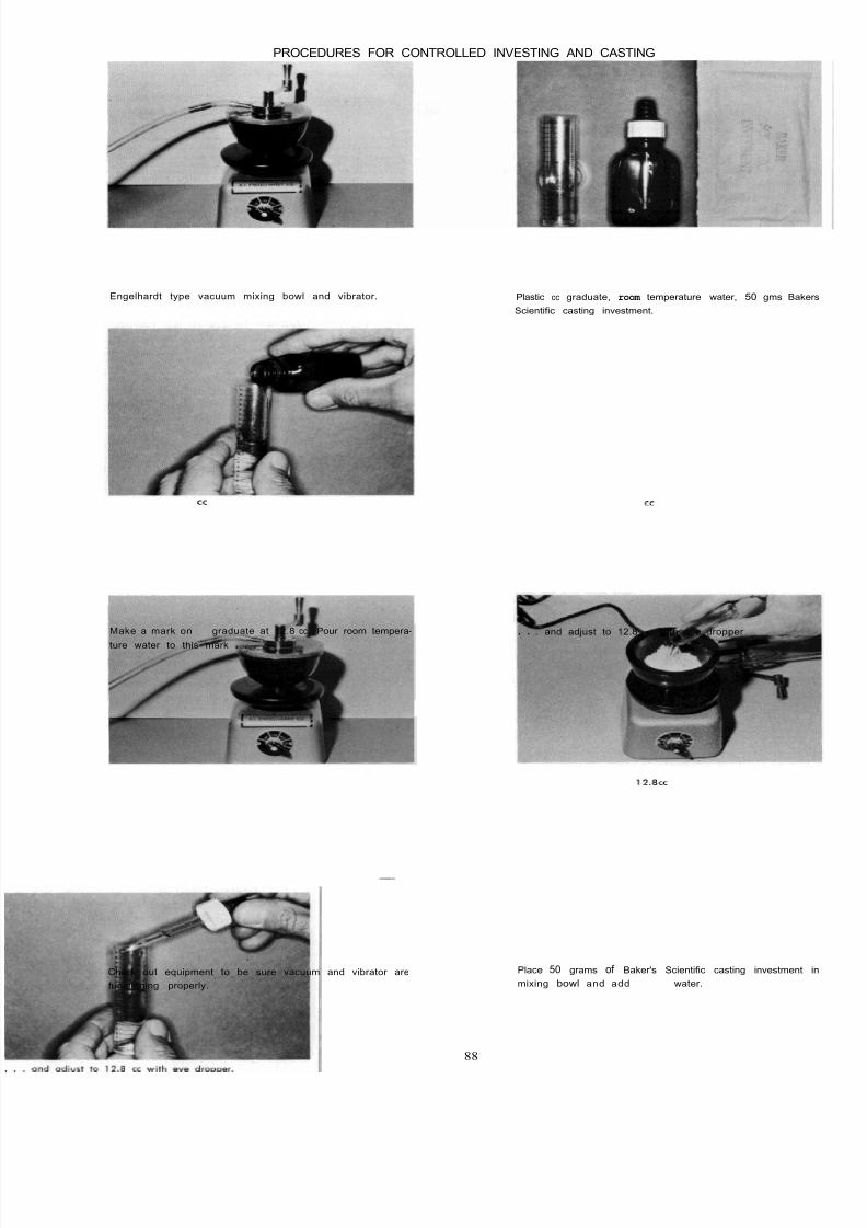
8/11/2019 An Atlas of Cast Gold Procedures
http://slidepdf.com/reader/full/an-atlas-of-cast-gold-procedures 93/270
PROCEDURES FOR CONTROLLED INVESTING AND CASTING
Engelhardt type vacuum mixing bowl and vibrator. Plastic cc graduate, room temperature water, 50 gms Bake
Scientific casting investment.
Make a mark on cc graduate at 12.8 cc. Pour room tempera-
ture water to this mark . . .
. . . and adjust to 12.8 cc with eye dropper
Check out equipment to be sure vacuum and vibrator are
functioning properly.
Place 50 grams of Baker's Scientific casting investment
mixing bowl and add 1 2 . 8 ~ ~water.
88

8/11/2019 An Atlas of Cast Gold Procedures
http://slidepdf.com/reader/full/an-atlas-of-cast-gold-procedures 94/270
Incorporate powder and water . . . . . . and vacuum mix the investment for 75 seconds using
heavy vibration.
Release vacuum and continue heavy vibration until all oi l
i s removed from the mix.
Support the ring and crater former on the fourth and little
finger and flow investment into ring using mild vibration.
Use core as the investment covers the pattern.
89
After ring i s filled, vibrate very mildly through the fingers
for 10 seconds. This procedure will permit the investment to
nestle close to pattern.

8/11/2019 An Atlas of Cast Gold Procedures
http://slidepdf.com/reader/full/an-atlas-of-cast-gold-procedures 95/270
Immerse ring in a 100' F. water bath for a minimum of
one -half hour.
Remove from water bath and allow to bench dry for
minutes or until investment is completely hardened.
. . . to soften the red counter wax around sprue. This p
cedure will permit removing the sprue without danger
fracturing investment around sprue hole.
Place crater former and ring in hot water . . .
Place ring in cold oven and set thermostatic control at 1250"
F. With this particular oven a complete burn-out i s accom-
plished at the end of one hour.
Preheat gold before placing ring in costing machine. Heat
proper temperature and cast.
90
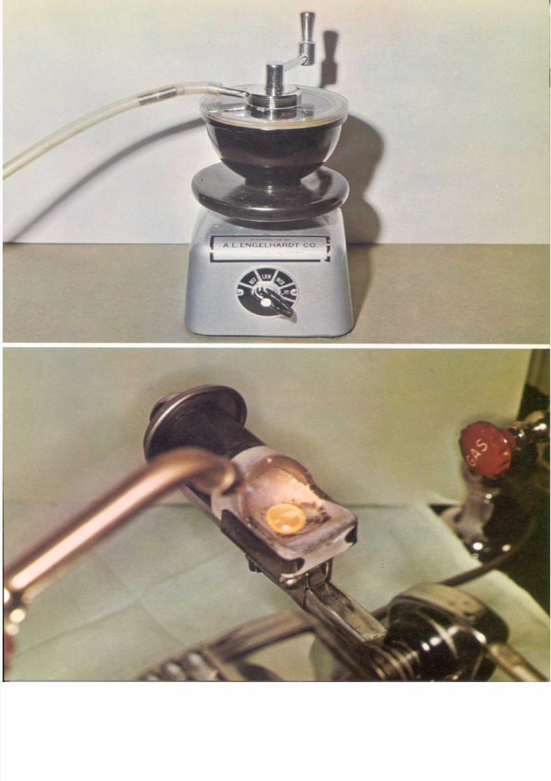
8/11/2019 An Atlas of Cast Gold Procedures
http://slidepdf.com/reader/full/an-atlas-of-cast-gold-procedures 96/270

8/11/2019 An Atlas of Cast Gold Procedures
http://slidepdf.com/reader/full/an-atlas-of-cast-gold-procedures 97/270
TOP PLATE
Vacuum mixing bowl and vibrator.
BOTTOM PLATE
Centrifugal vacuum casting machine.
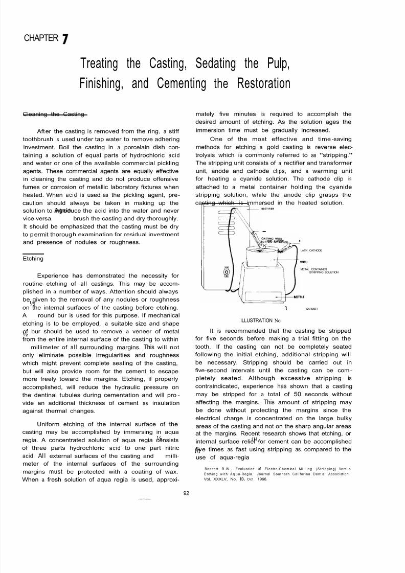
8/11/2019 An Atlas of Cast Gold Procedures
http://slidepdf.com/reader/full/an-atlas-of-cast-gold-procedures 98/270
CHAPTER 7
Cleaning the Casting
Treating the Casting, Sedating the Pulp,
Finishing, and Cementing the Restoration
After the casting i s removed from the ring, a stiff
toothbrush is used under tap water to remove adhering
investment. Boil the casting in a porcelain dish con-
taining a solution of equal parts of hydrochloric acid
and water or one of the available commercial pickling
agents. These commercial agents are equally effective
in cleaning the casting and do not produce offensive
fumes or corrosion of metallic laboratory fixtures when
heated. When acid i s used as the pickling agent, pre-
caution should always be taken in making up the
solution to introduce the acid into the water and never
vice-versa. Again brush the casting and dry thoroughly.
It should be emphasized that the casting must be dry
to permit thorough examination for residual investment
and presence of nodules or roughness.
Etching
Experience has demonstrated the necessity for
routine etching of al l castings. This may be accom-
plished in a number of ways. Attention should always
be given to the removal of any nodules or roughnesson the internal surfaces of the casting before etching.
AY
round bur is used for this purpose. If mechanical
etching i s to be employed, a suitable size and shape
of bur should be used to remove a veneer of metal
from the entire internal surface of the casting to within
l/2
millimeter of a l l surrounding margins. This will not
only eliminate possible irregularities and roughness
which might prevent complete seating of the casting,
but will also provide room for the cement to escape
more freely toward the margins. Etching, if properly
accomplished, will reduce the hydraulic pressure on
the dentinal tubules during cementation and will pro-
vide an additional thickness of cement as insulation
against thermal changes.
Uniform etching of the internal surface of the
casting may be accomplished by immersing in aqua
regia. A concentrated solution of aqua regia consists
of three parts hydrochloric acid to one part nitric
acid. Al l external surfaces of the casting andY
milli-
meter of the internal surfaces of the surrounding
margins must be protected with a coating of wax.
When a fresh solution of aqua regia is used, approxi-
mately five minutes is required to accomplish the
desired amount of etching. As the solution ages the
immersion time must be gradually increased.
One of the most effective and time-saving
methods for etching a gold casting is reverse elec-
trolysis which i s commonly referred to as "stripping."
The stripping unit consists of a rectifier and transformer
unit, anode and cathode clips, and a warming unit
for heating a cyanide solution. The cathode clip is
attached to a metal container holding the cyanide
stripping solution, while the anode clip grasps the
casting which i s immersed in the heated solution.
RED ANODE
LACK CATHODE
METAL CONTAINERWITH STRIPPING SOLUTION
8OTlLE WARMER
ILLUSTRATION No.
It is recommended that the casting be stripped
for five seconds before making a trial fitting on the
tooth. If the casting can not be completely seated
following the initial etching, additional stripping will
be necessary. Stripping should be carried out in
five-second intervals until the casting can be com-
pletely seated. Although excessive stripping is
contraindicated, experience has shown that a casting
may be stripped for a total of 50 seconds without
affecting the margins. This amount of stripping maybe done without protecting the margins since the
electrical charge i s concentrated on the large bulky
areas of the casting and not on the sharp angular areas
at the margins. Recent research shows that etching, or
internal surface relief for cement can be accomplished
five times as fast using stripping as compared to the
use of aqua-regia I ) .
1 B o s s e t t R . W . . E v a l u a t i o n of E l e c t r o -C h e m ic a l M i l l i n g ( S t r i p p i n g ) Ve rs u s
E t ch i n g w i t h A q u a -R e g i a . J o u r n a l S o u t h e r n C a l i f o r i n a D e n t a l A s s o c i at i o n ,
Vol. XXXLV, No. IO, O c t . 1966.
92
8/11/2019 An Atlas of Cast Gold Procedures
http://slidepdf.com/reader/full/an-atlas-of-cast-gold-procedures 99/270
A description of the electrochemical principles
involved in so-called "Stripping" has been submitted
by Dr. Joseph Smatko.* The following quotation is an
abridgement of Dr. Smatko's explanation and contains
a minimum of erudite electrochemical terminology:
In a sense, the slimming of dimensions of inlays
by this method may be considered as 'electrochemical
milling.' A special feature o f the solution and conditions
used is that sharp edges or pointed areas are more
slowly dissolved than areas of larger radii of curvature.This is in contrast to
electropolishing
which dissolves
sharp edges faster than broader areas. Polarization
phenomena are responsible for the selective action of
the proprietary solutions on gold inlays.
These cyanide solutions may contain a few or
several chemicals such as phosphates, sulfates, car -
bonates, hydroxides, silicates, etc., singly or in various
combinations. The additions of these salts have some
effect on pH and conductivity as well.
A simplified explanation of the mechanism may
involve one or more of the aspects of polarization.
Application of current causes oxidation o f the gold andformation of a soluble cyanide complex. At sharp
edges, a higher field gradient exists, creating a higher
current density. Besides the solution of the gold,
hydroxyl ion may discharge, oxygen gas may form,
cyanide concentration may drop quite low because of
dif fusion l imitations and because of destruction. In
other words, the efficiency of gold solution is lower
at the sharp edges than the flatter areas. I f the bath
contains the above cited organic materials, further
efficiency lowering is noted over broader ranges of
operating conditions. The exact mechanisms of opera-
tion of these organic materials is still the subject of
much study, especially in plating baths. Whatever the
mode of action, the effect is to reduce the rate of gold
solution over broader ranges of operation. The net
effect of al l these is to permit the holding of sharp
margins on inlays while slimming the dimensions else -
where to provide room for thin layers of cement."
Cleansina the Preparation and Pulp Sedation
Following the removal of the temporary
restoration preparatory to f i t t i n g and cementation
proceures, the tooth and i t s preparation must be
thoroughly cleansed of al l particles of cement andforeign material. It i s recommended that the prepara-
tion and al l adjacent tooth surfaces be thoroughly
scrubbed with fine wet flour of pumice using a rubber
cup and cotton pellets.
The favorable response of the pulp i s a ration-
* JosephS
Smatko, B.S., Chem. Eng.,(Ch.E.1
Chem. Eng.,Ph.D.,
Chem. Eng.
Electrochemical
consultant, presently senior scientist wi th Ho ffman Science
Center, Santa Barbara, Callfornia, engaged in fuel cell and batten/ re-
search. semiconductor plating and cooling methods.
a l
guide to acceptable procedures and materia
used in restoring teeth. Therefore, it is imperative tha
careful consideration be given to sedation of the toot
pulp which has been subjected to mechanical traum
and chemical irritation associated with routine restora
tive procedures. Before cementation of any casting
it is recommended that some form of pulp sedatio
be introduced.
Hyperemia is the most common post-operativ
symptom associated with the placement of restorationin teeth. Both the frequency and intensity of post-oper
ative hyperemia may be reduced by employing interim
treatment during the temporization period and b
using insulating and protective materials prior t
cementation.
Baume and Fiore-Donnol have reported that a
application of a calcium hydroxide liner, such a
Pulpdent is highly effective in providing lasting pro
tection against pulpal injuries because of filling ma
terials. These investigators have advocated a one t
two week calcium hydroxide treatment over denti
surfaces during temporization before the cementatio
of castings.2Clinical observations have indicated that varnish
type cavity liners are effective to some degree as
protectve medium under filling matrials. It is recog
nized that zinc phosphate cements produce unfavorabl
pulp responses when placed on freshly cut denti
surfaces. When cavity varnishes such as Copalite ar
used as a protective medium three applications ar
recommended to provide an effective seal against in
filtration of the irritating cement. It should be pointe
out that some of the commercial varnishes have
much greater f ilm thickness than others, but do no
necessarily provide a uniform, unbroken seal. If on
of the thicker products is used there should be greate
internal relief of the casting to provide the necessar
space for the material. After varnishes are applie
to the preparation a l l surrounding margins must b
thoroughly cleansed with a small pellet of cotto
moistened with chloform
In the presence of deep caries or pulp exposur
where special attention must be given to the protec
tion and treatment of the dental pulp, a calcium hy
droxide dressing covered with a layer of zinc oxid
bridge cement is considered to be the treatmnt o
choice. Crown and bridge cement may be placed ove
the treatment base for protection against pressure b
an interim or temporary restoration. Permanent restora
tion of the tooth may be completed if the toot
remains asymptomatic and retains vitality over a reas
onable length of time. Periodic pulp tests and radic
graphic examinations should be made periodically
The topical application of corticosteroid drugs on dee
I Baume, L.J., and Fiore-Donna. G., Response of the Human Pulp to
2. Baume, L.J., andFiore-Donno,
G. Personal communication.
3. Brauer, G.M., Mcloughlin, R., and Huget, E : The Use of Alu minum
Oxide as a Reinforcing Agent for Zinc OxideEugenol EBA cements
Presented I.A.D.R. meeting, Washington D.C., March, 1967.
New Restorative Material. JADA 76:1016 May, 1968.
93

8/11/2019 An Atlas of Cast Gold Procedures
http://slidepdf.com/reader/full/an-atlas-of-cast-gold-procedures 100/270
dentin wa l l s to reduce inflammatory pulp responses
a controversial issue.
A degree of clinical success i s reported in the
prevention of post-operative hyperemia with the newer
improved zinc oxide eugenol cements. Currently those
cements in which o-ethoxybenzoic acid (EBA) has been
substituted for a portion of the eugenol and reinforced
with aluminum oxide instead of quartz have been
reported3 to have tensile strength, fi lm thickness andresistance to solubility comparable to zinc phosphate
cements. Other properties relative to mixing, speed
of set, effect of moisture and characteristics of f lo w
must be understood if the best results are to be attain-
ed with these products. Only the test of time will
determine if these new materials can be relied upon
for routine cementation of both individual castings
and long-span fixed prosthodontic appliances.
to cavity preparation and cementation continues to be
Finishing the Casting
A well-organized finishing technique will improve
the appearance and prolong the life of any cast
restoration. The technique for finishing castings should
become so routine that it will not be unduly time
consuming. It can be said that finishing will be easier
and the end result better if each prior step is accom-
plished with skill and care.
There are certain fundamental principles involved
in the finishing and cementation of castings which
should be emphasized.
1. Space must be provided for the cement by
etching the casting.
2. The major par t of the finishing must be done
before cementation. If excessive finishing
is done following cementation, cement lines
will occur.
3. The casting must be held firmly in place at
al l times during finishing. Failure to observe
this principle will invariably result in injury
to the margins of the casting.
4. Careful consideration must be given to
th? mixing and consistency of the cement
for the particular type of casting to be
seated.
5. It is imperative that the preparation be kept
dry during cementation. This can usually be
best accomplished by use of the rubber dam.
The desired physical properties of zinc phosphate
cements are destroyed by contact with moisture. For
this reason it is advisable to adopt a method which
will keep the immediate operative field free from
moisture during cementation procedures. While it ispossible to maintain a dry field of operation with
antisialogogues, cotton rolls and hemostatic agents,
the rubber dam provides one of the easiest and most
practical methods for maintaining a consistently dry
field and clear vision of the working area. It is sug-
gested that the extra heavy gauge of rubber dam be
used in conjunction wi th cementation procedures. It
provides maximum retraction and protection of the
underlying soft tissues. If a lubricant i s applied to the
surface of extra heavy rubber dam, final disking and
polishing procedures can be carried out with greater
efficiency and fewer possibilities of injuring the dam
and underlying tissues.
94
8/11/2019 An Atlas of Cast Gold Procedures
http://slidepdf.com/reader/full/an-atlas-of-cast-gold-procedures 101/270
ARMAMENTARIUM FOR CLEANING CASTING, FINISHING AND CEMENTATION
CLEANING
TOOTHBRUSH
PYREX TEST TUBE
COMMERCIAL CLEANING AGENT (JELPAK)
FINISHING
I ROUND BUR
CUP SHAPED JOE DANDY DISC
STRIPPING UNIT
SPRAY BOTTLE WITH FINE FLOUR OF PUMICE
SULCI BURLEW WHEEL
ORANGE WOOD STICK
MALLET
DENTAL FLOSS
TYPEWRITER RIBBON
SMALL BUD BUR
1 1000 CELLOPHANE
BURNISHER
FINE PUMICE
HIGH LUSTRE POLISHING AGENT
MEDIUM AND FINE SANDPAPER DISCS
MEDIUM AND FINE GARNET PAPER DISCS
FINE CUTTLE DISCS
SOFT DIXON WHEEL BRUSH
RUBBER CUP AND END BRUSH
83,
64
WEIDELSTADT GOLD FILES
HOLDING INSTRUMENT
SMALL MOUNTED GREEN STONE
CEMENTATION
CEMENT SLAB
MEDART’S PRESSURE APPLICATOR
CEMENT SPATULA
CEMENT LIQUID AND POWDER
RUBBER DAM AND ACCESSORIES
SPECIAL BAYONET DESIGN SEATING INSTRUMENT
95

8/11/2019 An Atlas of Cast Gold Procedures
http://slidepdf.com/reader/full/an-atlas-of-cast-gold-procedures 102/270
PROCEDURES FOR CLEANING CAST NGS, FINISHING AND CEMENTATION
After casting is made, allow rtng to cool for 2 minutes be -
fore plunging in water. Remove castlng and scrub with tooth
brush and tap water.
Boil casting in Jelpak or one of the other commercial cleaning
agents. Scrubbing and boiling should be repeated until
casting is completely free of investment.
Remove any nodules or roughness with a I2 round bur Use a cup-shaped 1 dandy to cut sprue close to casting.
Stripping unit: Transformer rectifier, metal container and baby
bottle warmer.
Strip casting for 5 seconds
96

8/11/2019 An Atlas of Cast Gold Procedures
http://slidepdf.com/reader/full/an-atlas-of-cast-gold-procedures 103/270
The stripped casting i s now ready for adiustment of the
gingival plus, before fitting to the tooth.
The disc should be kept moving while rotating it in order
that full rounded contour be maintained. As this procedure
i s accomplished, the thin edge of gold will be curled slightly
inward. The initial adjustment remains as at "measurement"
X while outer portion Y is curled over.
Hold the disc at a 45 angle to the margin, rotate the disc
toward the margin, and remove only the curled edge of gold.
This will leave a slight excess of gold beyond the gingival
margin.
Adjust the ging iva l plus by rot ating the disc away from th
bulk of the casting.
Use the finger nail to bend the slightly curled margin outward
Use a spray bottle contuining fine flour of pumice [
eraser] to spray casting.
97

8/11/2019 An Atlas of Cast Gold Procedures
http://slidepdf.com/reader/full/an-atlas-of-cast-gold-procedures 104/270
Seat casting with finger pressure.
. . . with a reshaped sulci Burlew wheel.
Check position, shape, size and tightness o f contact areos
with dental floss:
Adjust the tight contact area . . .
. ___
After contact areas have been adlusted, seat casting with
mallet farce
The casting i s now ready for final occlusal adjustments.
98

8/11/2019 An Atlas of Cast Gold Procedures
http://slidepdf.com/reader/full/an-atlas-of-cast-gold-procedures 105/270

8/11/2019 An Atlas of Cast Gold Procedures
http://slidepdf.com/reader/full/an-atlas-of-cast-gold-procedures 106/270
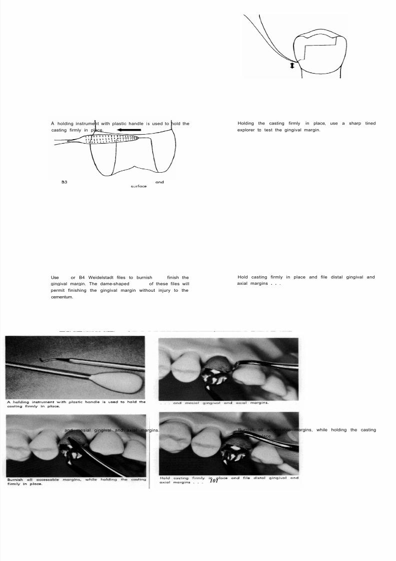
8/11/2019 An Atlas of Cast Gold Procedures
http://slidepdf.com/reader/full/an-atlas-of-cast-gold-procedures 107/270
A holding instrument with plastic handle i s used to hold the
casting firmly in place.
Holding the casting firmly in place, use a sharp tin
explorer to test the gingival margin.
Use 83 or B4 Weidelstadt files to burnish and finish the
gingival margin. The dame-shaped surfoce of these files will
permit finishing the gingival margin without injury to the
cementum.
Hold casting firmly in place and file distal gingival a
axial margins . . .
and mesial gingival and axial margins.
101
Burnish all accessable margins, while holding the cast
firmly in place.

8/11/2019 An Atlas of Cast Gold Procedures
http://slidepdf.com/reader/full/an-atlas-of-cast-gold-procedures 108/270
If necessary, rotate a true running mounted stone over mar -
gins, rotating the stone from the gold toward the tooth.
Hold the casting firmly in place and disc all accessible
margins, using fine sand or garnet discs. Always rotate disc
from the gold toward the tooth.
Remove casting . . , and if necessary, refine occlusal anatomy with a small
bud bur and . . .
. , , carefully remove any rough areas with a reshaped
sulci Burlew disc.
Armamentarium for cementation: Cement slab, Medart's pres-
sure applicator a nd spatula, cement liqu id and powder,
mallet, rubber dam and holder, rubber dam napkin, holding
instrument, wooden dowel and special bayonet seating in -
strument an d rubber dam clamp forceps. The bayonet-type
seating instrument permits application of optimum line of
farce when seating castings on the posterior teeth.
102
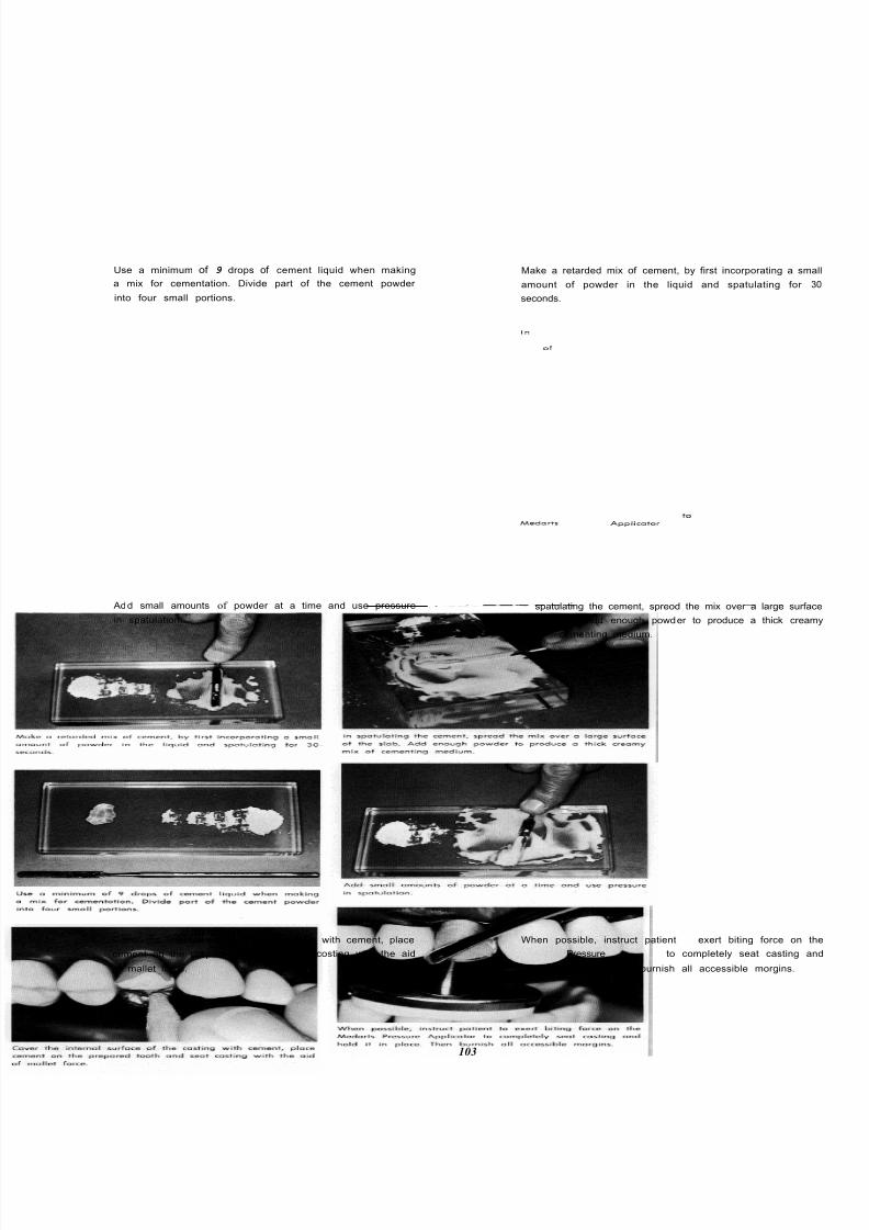
8/11/2019 An Atlas of Cast Gold Procedures
http://slidepdf.com/reader/full/an-atlas-of-cast-gold-procedures 109/270
Use a minimum of 9 drops of cement liquid when making
a mix for cementation. Divide part of the cement powder
into four small portions.
Make a retarded mix of cement, by first incorporating a sm
amount of powder in the liquid and spatulating for
seconds.
Add small amounts of powder at a time and use pressure
in spatulation.
In spatulating the cement, spreod the mix over a large surfa
of the slab. Add enough powder to produce a thick cream
mix of cementing medium.
Cover the internal surface of the casting with cement, place
cement on the prepared tooth and seat costing with the aid
of mallet force.
When possible, instruct patient to exert biting force on t
Medarts Pressure Applicotor to completely seat casting a
hold it in place. Then burnish all accessible morgins.
103
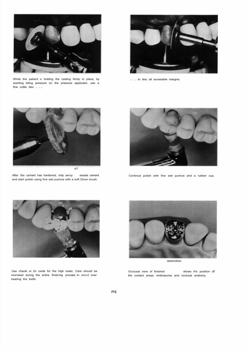
8/11/2019 An Atlas of Cast Gold Procedures
http://slidepdf.com/reader/full/an-atlas-of-cast-gold-procedures 110/270

8/11/2019 An Atlas of Cast Gold Procedures
http://slidepdf.com/reader/full/an-atlas-of-cast-gold-procedures 111/270

8/11/2019 An Atlas of Cast Gold Procedures
http://slidepdf.com/reader/full/an-atlas-of-cast-gold-procedures 112/270
TOP PLATE
Stripping Unit.
BOTTOM PLATE
Stripping unit in action.

8/11/2019 An Atlas of Cast Gold Procedures
http://slidepdf.com/reader/full/an-atlas-of-cast-gold-procedures 113/270
8/11/2019 An Atlas of Cast Gold Procedures
http://slidepdf.com/reader/full/an-atlas-of-cast-gold-procedures 114/270
The difficulties encountered in obtaining full
circumferential retraction when the finish line is placed
one to one and one-half millimeters under the free
gingiva often results in the operator designing the
preparation to simplify the impression procedures.
Needless to say this decision to establish the margin
of the preparation closer to the height of the gingival
tissues often leads to recurrence of caries as a result
of placing the margin of the restoration in an unclean
area. On the other hand, obtaining adequate retraction
of the tissues beyond the finish line in al l areas can
be extremely difficult to accomplish if the finish line
is extended the desired distance under the protection
of the free gingiva. Clinical evidence shows that many
full crown restorations have been constructed on dies
made from an impression which was an incomplete
reproduction of the finish line of the preparation. It
must also be pointed out that the combination of
prolonged retraction with cotton strands impregnated
with a vas0 constrictor held in position under pressure
often result in irreparable tissue damage. In such
instances even though the margin of the restoration
may be beneath the crest of the free gingiva at the
time of cementation, subsequent recession of tissue
traumatized in this manner may occur in a few days
or within a period of a few months. In either instance,
this recession results in the margin of the restoration
terminating in an unclean area predisposing early
failure. It is obvious that extreme care must be exer -
cised in obtaining retraction for making full crown
impressions. (Tissue management i s described and
illustrated in Chapter 4.)
Tube Impressions Using Rubber Base Materials
Another method for obtaining accurate impressions
of full crown type preparations is the tube technique
which i s being employed successfully by many oper -
ators. This technique offers certain advantages
particularly in difficult cases. The most salient feature
is the principle of confinement which permits the
impression material to be carried beyond the greatest
extension of the finish line under positive pressure.
When using the tube in combination with heavy-bodied
material, tissue retraction may not be necessary. It i s
important, however, to control hemorrhage. This can
be accomplished most effectively by directing three
percent hydrogen peroxide into the gingival creviceunder pressure from a spray bottle. For hemorrhage
control this application of peroxide must be continued
until the crest of the gingival tissue is blanched. After
rinsing the mouth with warm water the operating area
should be isolated with cotton rolls. The preparation
and adjacent tissues should not be dried with air
pressure until just prior to making the impression.
Recurrence of hemorrhage will often appear in a rela-
tively short time following the application of air.
In making impressions of full crown preparations
the heavy-bodied rubber base type of materials offer
certain advantages over reversible agar hydrocolloid.
These advantages are:
1. Minimal need for tissue retraction.
2. Thin frail edges of the impression material
will be retained.
3. These materials may be copper or silver
plated. (Note: It is recommended that cop-
per plating be used for the silicone and
silver plating for Polysulfide impression.)
Synthetic composition rubbers were first adoptedfor use as dental impression materials in 1953. Al-
though these synthetic rubber materials have been
used extensively for many years in industry, it was
necessary to modify them for dental application by
adding fillers, plasticizers, retarders and odor masking
agents. They are essentially liquid polymers which can
be converted to solid rubbers at room temperature by
being mixed with a suitable catalyst. The rubber base
and the catalyst are mixed when required and the
resulting paste sets to a semisolid rubber in the mouth.
The synthetic rubber materials are classified as
mercaptan polysulfides and silicone polymers. The
polysulfides are sometimes called Thiokol rubbers
which refers to the name of the manufacturer. In
recent years the polysulfides and silicone polymers
have been greatly improved and are being more
widely accepted by the dental profession as accurate
impression materials.
Work done by Hollenback indicates that
acceptably accurate working dies and models can be
obtained with either of these types of synthetic rubber
base materials if the impressions are poured within a
time limit of 30 to 60 minutes. He reported that
dimensional changes occurred to some extent when
the impressions were stored appreciably longer.
* I
Dr. George M. Hollenbock and Research Associates, Journal Southern
California State Dental Association, Nov. 1963.
107

8/11/2019 An Atlas of Cast Gold Procedures
http://slidepdf.com/reader/full/an-atlas-of-cast-gold-procedures 115/270
ARMAMENTARIUM FOR FULL VENEER FINISH LINE CROWN
PREPARATION AND INITIAL STEPS FOR TEMPORIZING
TEMPORIZING
WA XING PLIERS
KERR'S RED UTIL ITY WAX
PERFORATED TRAY
D.P. ALGINATE IMPRESSION MATERIAL
PREPARATION
SMALL FLAME SHAPED DIAMOND STONE
SMALL DOUGHNUT SHAPE STONE
PINK BASEPLATE WAX
BOLEY MILLIMETER GAUGE
MEDIUM SIZE BULLET SHAPED DIAMONDS T OM
SMALL BULLET SHAPE DIAMOND STONE
WHITE POLY STONE
700 TAPER FISSURE BUR
FINE PUMICE
RUBBER CUP
108

8/11/2019 An Atlas of Cast Gold Procedures
http://slidepdf.com/reader/full/an-atlas-of-cast-gold-procedures 116/270
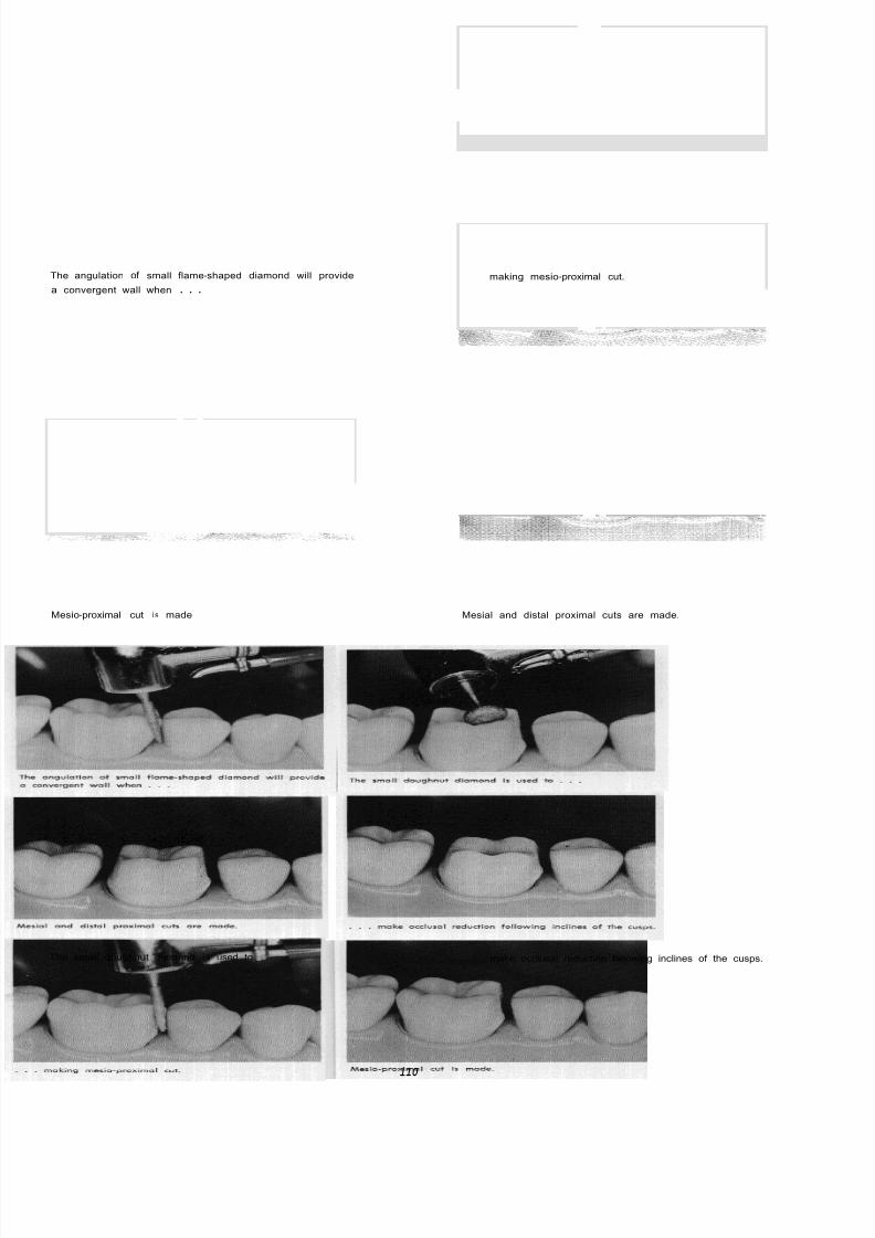
8/11/2019 An Atlas of Cast Gold Procedures
http://slidepdf.com/reader/full/an-atlas-of-cast-gold-procedures 117/270
The angulation of small flame-shaped diamond will provide
a convergent wall when . . .
Mesio-proximal cut i s made
making mesio-proximal cut.
Mesial and distal proximal cuts are made.
The small doughnut diamond i s used to make occlusal reduction fallowing inclines of the cusps.
110
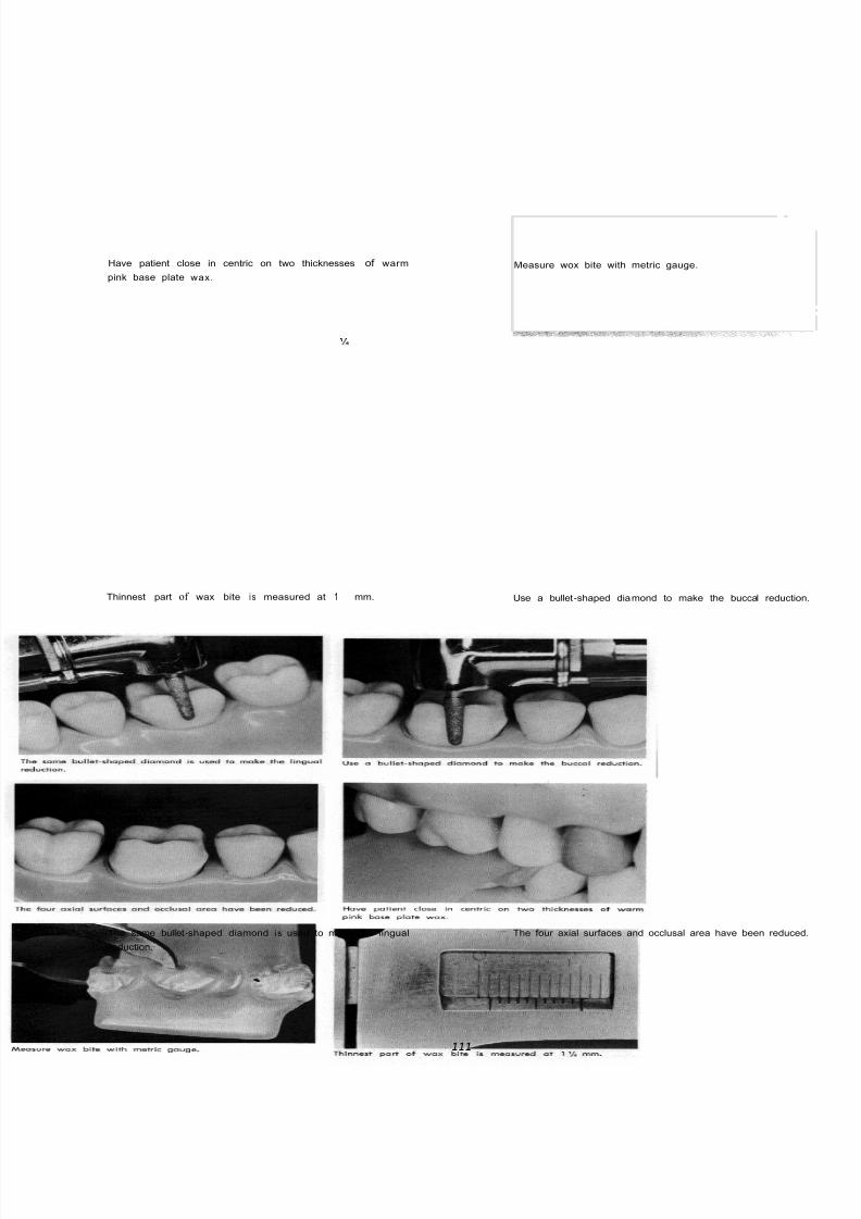
8/11/2019 An Atlas of Cast Gold Procedures
http://slidepdf.com/reader/full/an-atlas-of-cast-gold-procedures 118/270
Have patient close in centric on two thicknesses of warm
pink base plate wax.
Measure wox bite with metric gauge.
Thinnest part of wax bite i s measured at 1 mm.
The same bullet-shaped diamond i s used to make the lingual
reduction.
Use a bullet-shaped diamond to make the buccal reductio
The four axial surfaces and occlusal area have been reduce
111

8/11/2019 An Atlas of Cast Gold Procedures
http://slidepdf.com/reader/full/an-atlas-of-cast-gold-procedures 119/270
Extend and refine finish line chamfer with small bullet -nose
diamond.
Blend sharp angulations and . . .
refine occlusal reduction Buccal chamfered finish line and occlusal reduction. (Author's
note: The finish line should be placed under the free gingiva
where practical. Thisi s
possible without permanent damageto tissue. In the preparation of these models, the base i s hard
and the ideal finish line relation to gingiva is not possible.)
Smooth any roughness of preparation with re -shaped white
polystone.
Buccal chamfered finish line and occlusal reduction.
112
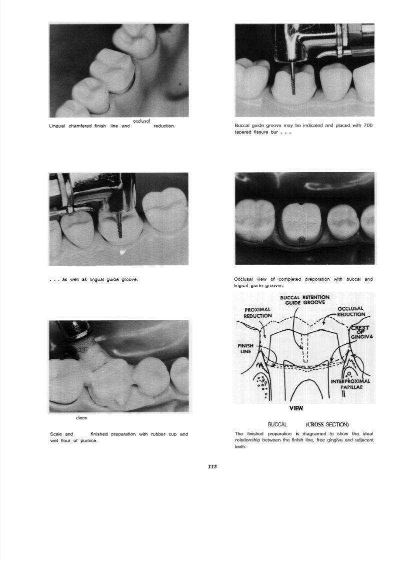
8/11/2019 An Atlas of Cast Gold Procedures
http://slidepdf.com/reader/full/an-atlas-of-cast-gold-procedures 120/270
Lingual chamfered finish line and occlusol reduction.
. . . as well as lingual guide groove.
Scale and cleon finished preparation with rubber cup and
wet flour of pumice.
Buccal guide groove may be indicated and placed with 70
tapered fissure bur . . .
Occlusal view of completed preporation with buccal an
lingual guide grooves.
BUCCAL VIEW: (CROSS SECTION)
The finished preparation is diagramed to show the ide
relationship between the finish line, free gingiva and adjacen
teeth.
9

8/11/2019 An Atlas of Cast Gold Procedures
http://slidepdf.com/reader/full/an-atlas-of-cast-gold-procedures 121/270
ARMAMENTARIUM FOR IMPRESS10N OF FULL VENEER FINISH LINE
CROWN AND FABRICAT1NG T E MPORARY PLASTIC RESTORATION
IMPRESSIONS
ASSORTED SOFT COPPER TUBES
CROWN AND COLLAR SCISSORS
CONTOURING PLIERS
LARGE BULLET SHAPED DIAMOND STONE
BUNSEN BURNER
ETHYL ALCOHOL
GREEN STICK COMPOUND
COTTON PLIERS
#6, &7 AN D 0 ROUND BURS
KERR'S HEAVY-BODIED ELASTICON, ACCELERATOR
AN D ACCESSORIES
KERR'S SYRINGE ELASTICON AND ACCELERATOR
ELASTICON ADHESIVE [SOLVENT XYLOL)
ELASTICON PAPER MIXING PAD AND SPATULA
7 WAX SPATULA
ASBESTOS
KERR'S COLD CURE PLASTIC TRAY MATERIAL
COE CHECK-BITE TRAY
HYDROCOLLOID CONDITIONER AND ACCESSORIES
TEMPORIZING
SELF- ACTIVATING RESIN (COLD CURE PLASTIC)
ZINC OXIDE EUGENOL CEMENT
4
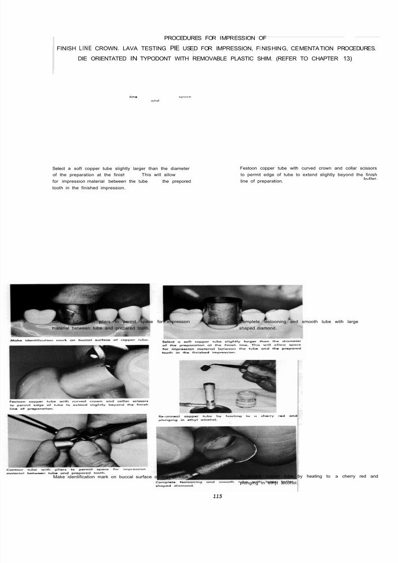
8/11/2019 An Atlas of Cast Gold Procedures
http://slidepdf.com/reader/full/an-atlas-of-cast-gold-procedures 122/270
PROCEDURES FOR IMPRESSION OF
FINISH LINE CROWN. LAVA TESTING PIE USED FOR IMPRESSION, FINISHING, CEMENTATION PROCEDURE
DIE ORIENTATED IN TYPODONT WITH REMOVABLE PLASTIC SHIM. (REFER TO CHAPTER 13)
Select a soft copper tube slightly larger than the diameter
of the preparation at the finish line This will allow space
for impression material between the tube and the prepored
tooth in the finished impression.
Festoon copper tube with curved crown and collar sciss
to permit edge of tube to extend slightly beyond the fin
line of preparation.
Contour tube with pliers to permit space for impression
material between tube and prepared tooth.
Complete festooning and smooth tube with large bull
shaped diamond.
Make identification mark on buccal surface of copper tube. Re-anneal copper tube by heating to a cherry red a
plunging in ethyl alcohol.
115
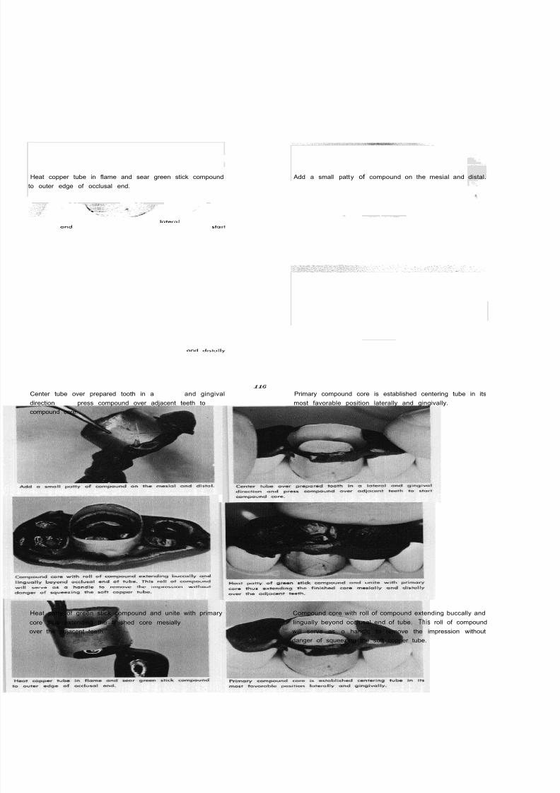
8/11/2019 An Atlas of Cast Gold Procedures
http://slidepdf.com/reader/full/an-atlas-of-cast-gold-procedures 123/270
Heat copper tube in flame and sear green stick compound
to outer edge of occlusal end.
Center tube over prepared tooth in a lateral and gingival
direction and press compound over adjacent teeth to start
compound core.
Heat patty of green stick compound and unite with primary
core thus extending the finished core mesially and distally
over the adjacent teeth.
Add a small patty of compound on the mesial and distal.
Primary compound core is established centering tube in its
most favorable position laterally and gingivally.
Compound core with roll of compound extending buccally and
lingually beyond occlusal end of tube. This roll of compound
will serve as o handle to remove the impression without
danger of squeezing the soft copper tube.
6

8/11/2019 An Atlas of Cast Gold Procedures
http://slidepdf.com/reader/full/an-atlas-of-cast-gold-procedures 124/270
Remove from the inside of the tube that portion of compound
which touches the prepared tooth.
Drill escape way hole through center of compound.
Apply diluted Elasticon- Adhesive (solvent xylol) to inside
and outside of copper tube.
Armamentarium for controlled copper tube technique usin
heavy-bodied Elasticon.
Armamentarium for syringe Elasticon. Two inches of heavy-bodied Elasticon with four drops of re
accelerator ond one drop of syringe accelerator. These pro
portions will decrease working time and permit the operato
to make the tube impression in four and one-half to five
minutes.
7
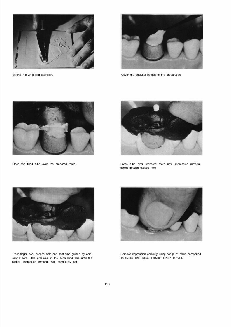
8/11/2019 An Atlas of Cast Gold Procedures
http://slidepdf.com/reader/full/an-atlas-of-cast-gold-procedures 125/270
Mixing heavy-bodied Elasticon. Cover the occlusal portion of the preparation.
Place the filled tube over the prepared tooth.
Place finger over escape hole and seat tube guided by com-
pound core. Hold pressure on the compound core unt il the
rubber impression material has completely set.
Press tube over prepared tooth until impression material
comes through escape hole.
Remove impression carefully using flange of rolled compound
on buccal and lingual occlusal portion of tube.
118

8/11/2019 An Atlas of Cast Gold Procedures
http://slidepdf.com/reader/full/an-atlas-of-cast-gold-procedures 126/270
119

8/11/2019 An Atlas of Cast Gold Procedures
http://slidepdf.com/reader/full/an-atlas-of-cast-gold-procedures 127/270
120
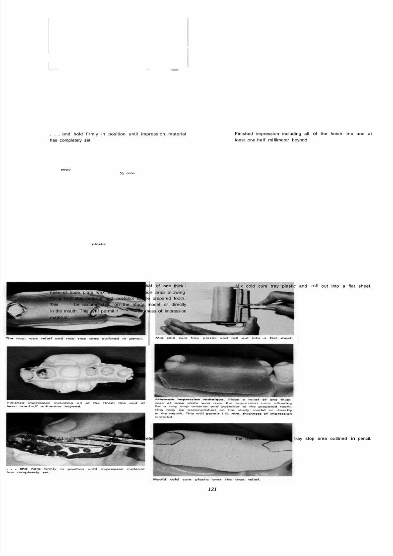
8/11/2019 An Atlas of Cast Gold Procedures
http://slidepdf.com/reader/full/an-atlas-of-cast-gold-procedures 128/270
. . . and hold firmly in position until impression material
has completely set.
Alternate impression technique. Place a relief of one thick -
ness of base plate wax over the impression area allowingfor a tray stop anterior and posterior to the prepared tooth.
Thismay
be accomplished on the study model or directly
in the mouth. This will permit 1mm.
thickness of impression
material.
Mould cold cureplostic
over the wax relief.
Finished impression including all of the finish line and
least one-ha If miIlimeter beyond.
Mix cold cure tray plastic and roll out into a flat she
The troy, wax relief and tray stop area outlined in penc
121

8/11/2019 An Atlas of Cast Gold Procedures
http://slidepdf.com/reader/full/an-atlas-of-cast-gold-procedures 129/270
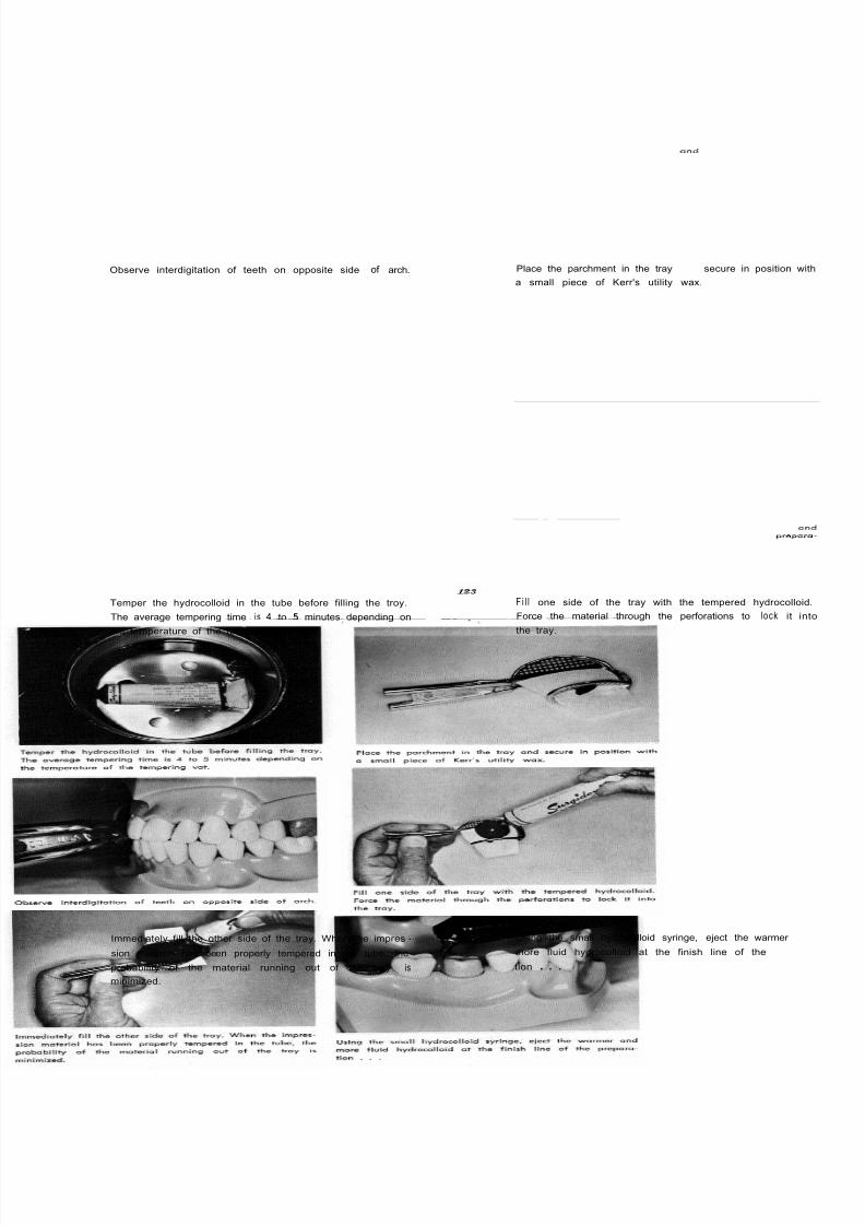
8/11/2019 An Atlas of Cast Gold Procedures
http://slidepdf.com/reader/full/an-atlas-of-cast-gold-procedures 130/270
Observe interdigitation of teeth on opposite side of arch. Place the parchment in the tray and secure in position wi
a small piece of Kerr's utility wax.
Temper the hydrocolloid in the tube before filling the troy.
The average tempering time i s 4 to 5 minutes depending on
the temperature of the tempering vat.
F i l l one side of the tray with the tempered hydrocolloid
Force the material through the perforations to lock it in
the tray.
Immediately fill the other side of the tray. When the impres -
sion materi al has been properly tempered in the tube, the
probability of the material running out of the tray is
minimized.
Using the small hydrocolloid syringe, eject the warmer an
more fluid hydrocolloid at the finish line of the prepor
tion . . .
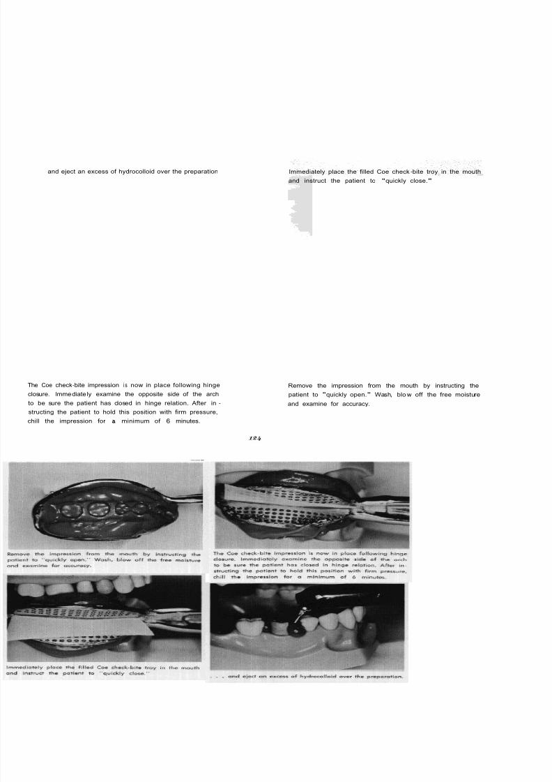
8/11/2019 An Atlas of Cast Gold Procedures
http://slidepdf.com/reader/full/an-atlas-of-cast-gold-procedures 131/270
and eject an excess of hydrocolloid over the preparation
The Coe check-bite impression i s now in place following hinge
closure. Immediate ly examine the opposite side of the arch
to be sure the patient has closed in hinge relation. After in -
structing the patient to hold this position with firm pressure,
chill the impression for a minimum of 6 minutes.
Immediately place the filled Coe check-bite troy in the mouth
and instruct the patient to "quickly close."
Remove the impression from the mouth by instructing the
patient to "quickly open." Wash, blo w off the free moisture
and examine for accuracy.
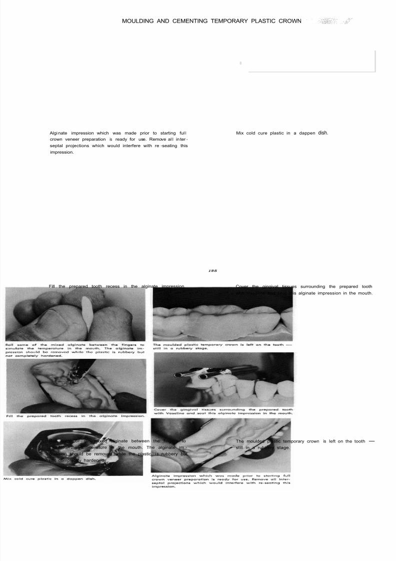
8/11/2019 An Atlas of Cast Gold Procedures
http://slidepdf.com/reader/full/an-atlas-of-cast-gold-procedures 132/270
MOULDING AND CEMENTING TEMPORARY PLASTIC CROWN
Algi nate impression which was made prior to starting ful l
crown veneer preparation is ready for use. Remove al l in ter -
septal projections which would interfere with re -seating this
impression.
Mix cold cure plastic in a dappen dish.
Fill the prepared tooth recess in the alginate impression. Cover the gingival tissues surrounding the prepared too
with Vaseline and seat this alginate impression in the mout
Roll some of the mixed alginate between the fingers to
simulate the temperature in the mouth. The alginate im -
pression should be removed while the plastic i s rubbery but
not completely hardened.
The moulded plastic temporary crown is left on the tooth -
still in a rubbery stage.

8/11/2019 An Atlas of Cast Gold Procedures
http://slidepdf.com/reader/full/an-atlas-of-cast-gold-procedures 133/270
Remove plastic temporary crown from the tooth using a
curved explorer.
Occlusal view of plastic temporary crown as it appears when
taken from the tooth.
Gingival view of plastic temporary crown which must now be
trimmed to the finish line and '/4 mm short of ftnlsh line,
contoured and polished
Mix zinc-oxide eugenol cement to a semi-thick consistency.
F i l l the polished temporary plastic crown with cement.
126
Temporary plastic crown cemented with all excess cement
removed.
. . . . .. . . . . .. . ... . .

8/11/2019 An Atlas of Cast Gold Procedures
http://slidepdf.com/reader/full/an-atlas-of-cast-gold-procedures 134/270
ARMAMENTARIUM FOR COPPER PLATING, PREPARATION OF MODELS
WAXING, INVESTING, WAX ELIMINATION, CASTING, CLEANSING
CASTING, FINISHING AND CEMENTATION
COPPER PLATING
FINE CAMEL HAIR BRUSH
MICROFILM LlOUlD
METALIZING POWDER
30 GAUGE WAX
BARD PARKER KNIFE
7 SPATULA
RED COUNTER WAX
ETHYL ALCOHOL AND EYE DROPPER
COPPER PLATING MACHINE AND ACCESSORIES
PREPARATION OF MODELS
50% ZINC CHLORIDE
GLUED WRAPPING PAPER
CERRABEND OR NEY'S DIE ALLOY
MEDIUM SAND PAPER DISC
COARSE ARBOR-BAND AND CHUCK
LARGE CARBIDE ACRYLIC BUR OR HEATLESS STONE
#36 INVERTED CONE BUR
MINERAL OIL
MODEL TRIMMER
STEPHAN MODEL "D" ARTICULATOR
WAXING
CAMEL HAIR BRUSH
WAXING PLIERS
THOMPSON WAX CARVER
KERR'S WAX-UP WAX
HARD INLAY WAX
CARBON TETRACHLORIDE
SLIK-DIE LUBRICANT
FINE SOFT SILK
BUNSEN BURNER AND METAL DISH
TALCUM POWDER
18 GAUGE HOLLOW SPRUE
700 PLASTIC PIN (WILKINSON)
8/11/2019 An Atlas of Cast Gold Procedures
http://slidepdf.com/reader/full/an-atlas-of-cast-gold-procedures 135/270
INVESTING
CRATER FORMER
CASTING RING
ASBESTOS LINER
50 GRAMS BAKER SCIENTIFIC INVESTMENT
ROOM TEMPERATURE WATER
PLASTIC CC GRADUATE
VACUUM PUMP
VIBRATOR
VACUUM MIXING BOWL AND ACCESSORIES
100" F. WATER BATH (ENGELHARDT AND CO.)
WAX ELIMINATION AND CASTING
THERMOSTICALLY
CONTROLLED BURN-OUT OVEN
GAS- AIR OR GAS-OXYGEN TORCH
CASTNG MACHINE
CLEANSING CASTING, FINISHING, CEMENTATION
PYREX TEST TUBE
COMMERCIAL CLEANING AGENT (JELPAK)
ULTRA-SONIC CLEANING MACHINE
STRIPPING UNIT
CUP SHAPED JOE-DANDY
ASSORTED BURLEW WHEELS
SMALL BUD BUR
METRI-CALIPER
ROUND BUR
699 X LONG BUSCH BUR
VASELINE
4 ROUND BUR
TYPEWRITER RIBBON
1/ 1000 CELLOPHANE
FINE FLOUR OF PUMICE
SOFTDIXON
BRUSH
RAG WHEEL
HIGH LUSTRE POLISHING AGENT
CEMENT SLAB
CEMENT SPATULA
CEMENT POWDER AND LIQUID
MEDART'S PRESSURE APPLICATOR (LONG LEG)
SPECIAL HOLDING INSTRUMENT
BAYONET-TYPE SEATING INSTRUMENT
LARGE ROUND SERRATED AMALGAM CONDENSER
ORANGE WOOD STICK
SEATING MALLET
WIRE CUTTING PLIERS
DOUBLE XX COARSE WET-0-DRY DISC
FINE CUTTLE DISC
I28

8/11/2019 An Atlas of Cast Gold Procedures
http://slidepdf.com/reader/full/an-atlas-of-cast-gold-procedures 136/270
PROCEDURES FOR FABRICATION OF MODELS, WAXING, INVESTING, WAX ELIMINATION, CASTING.
Before sensitizing the rubber -base impression, burnish a very
light film of microfilm over the entire impression. Then sensi-
tize the impression by dusting with metalizing powder using
a camel hair brush.
Wrap slightly warmed 30-gauge wax around the tube i
Dression . . .
. . . and allow it to extend /a inch beyond the impression.
Apply warmed red counter wax to seal the copper tube in
contact with the copper plating carrier.
129
Use a sharp Bard-Parker knife to scrape and expose the e
of the copper tube so that it will make contact with t
base of the copper plating carrier.
Fi l l the impression with ethyl-alcohol before placing in copp
plating solution. The alcohol serves as a wetting agent an
will prevent the trapping of air.

8/11/2019 An Atlas of Cast Gold Procedures
http://slidepdf.com/reader/full/an-atlas-of-cast-gold-procedures 137/270
Place the impression in the copper sulfate solution of the
copper plating machine.
Coat the surface of copper with a film of 50% zinc chloride.
This will act as a flux and permit a union of the low fusing
metal to the copper.
Using the Bunsen burner, liquify Cera-Bend, or Neys Die
Alloy and pour into the paper form to make the root portion
of the die.
All ow the impression to plate a minimum of 15 hours. This
will produce a heavy deposit ion of copper result ing in a
strong die.
Wrap ’? inch of glued wrapping paper around the copper -
plated die.
Separate the die from the impression.
130

8/11/2019 An Atlas of Cast Gold Procedures
http://slidepdf.com/reader/full/an-atlas-of-cast-gold-procedures 138/270
Copper -plated die wit h low fusing metal root. Armamentarium for preparing the root portion of the d
From lef t to righ t: fi ne sandpaper disc, carbo. disc, die, coa
arbor band and chuck, heatless stone.
Use an acrylic bur or heatless stone to remove any excess
copper or l ow fusing metal near the margins of the die.
Further refine the taper of the root portion of the die with
a carbo. disc. Cut a fla t pl ane on the buccal portion of the
root
. . .
Taper the die with o coarse arbor band.
. . . and smooth the taper with a fine sandpaper disc
131
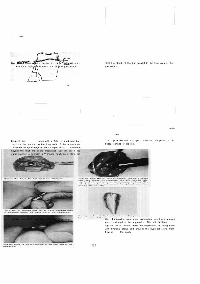
8/11/2019 An Atlas of Cast Gold Procedures
http://slidepdf.com/reader/full/an-atlas-of-cast-gold-procedures 139/270
Use a No. 37 inverted cone bur to cut a V -shaped notch
millimeter beyond the finish line of the preparation.
Establish theVlshaped
notch with a #37 inverted cone bur
Hold the bur parallel to the long axis of the preparation.
Terminate the upper edge of the V-shaped notch ’/, millimeter
beyond the finish line of the preparation. Use this bur in the
same manner to establish a V-shaped notch on a stone die.
Position the die in the Coe check-bite impression.
Hold the shank of the bur parallel to the long axis of the
preparation.
The copper die with V-shaped notch and flat plane on the
buccal surface of the root.
With the small syringe, eject hydrocolloid into the V-shaped
notch and against the impression. This will facilitate hoid-
ing the die in position while the impression i s being filled
with hydrocal stone and prevent the hydrocal stone from
flowinginto
the notch.
132

8/11/2019 An Atlas of Cast Gold Procedures
http://slidepdf.com/reader/full/an-atlas-of-cast-gold-procedures 140/270
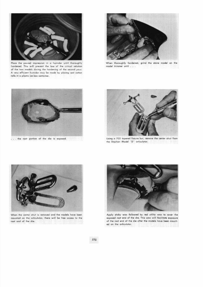
8/11/2019 An Atlas of Cast Gold Procedures
http://slidepdf.com/reader/full/an-atlas-of-cast-gold-procedures 141/270

8/11/2019 An Atlas of Cast Gold Procedures
http://slidepdf.com/reader/full/an-atlas-of-cast-gold-procedures 142/270
Try the unseparated models in the articulator for align -
ment . . .. . . and attach to the bows of the articulator with plas
of paris.
After the plaster mount ing has hardened, separate the at -
tached models from the Coe check-blte lmpresslon by open-
ing the bows of the articulator. Remove the hydrocolloid
from around the die . . .
Use a laboratory knife to expose the wox which was placed
over the root end of the die.
. . . leaving the margins of the die fully exposed for w
ing procedures.
After the wax has been removed, the root end of the
will be visible, exactly flush wi th the surface of the st
model. This will permit the operator to observe the die
it i s correctly seated in the model.
135

8/11/2019 An Atlas of Cast Gold Procedures
http://slidepdf.com/reader/full/an-atlas-of-cast-gold-procedures 143/270
The articulated models with die removed Articulated models in hydrocol stone mode from an agar
reversible hydrocolloid impression using the Coe check-bite tray.
A hydracal stone master die may be made from a tube im-
pression as previously described or from an agar reversible
hydrocolloid impression. Make a V-shaped notch with a
number 37 inverted cone bur. Use slow speed and hol d the
bur porallel to the long axis of die.
The armamentarium for waxing procedure. From left to right:
camel hair brush; woxing pliers; Thompson wox carver;
Kerr's wax-up wax; Kerr's hard inlay wax in metal dish;
wax -up wax in metal dish; carbon tetrachloride; Slik-Die
lubricant.
This technique of establishing a V-shaped notch, '/, mm. be-
yond the finish line of the preparation may be applied to bath
the full and three-quarter crown stone dies.
Liquefy the Kerr's inlay wax in the metal dish.
136

8/11/2019 An Atlas of Cast Gold Procedures
http://slidepdf.com/reader/full/an-atlas-of-cast-gold-procedures 144/270
Lubricate the die with Slik-Die.
Hold the die between the thumb and index finger ready to
be dipped into the molten wax.
. . . and remove. This will place a layer of wax on the
die and as the wax cools it will shrink toward the surface
of the die.
Warm the copper -plated die over the Bunsen burner.
Quickly dip the die into the molten wax . . .
Dip the die again, remove and twir l between the finger
By repeating this procedure the bulk and general contou
of the pattern may be established with facility.
137

8/11/2019 An Atlas of Cast Gold Procedures
http://slidepdf.com/reader/full/an-atlas-of-cast-gold-procedures 145/270
With the waxing pliers, make further additions of wax to
establish the desired contour.
If the pattern i s too wide, soften and remove some of the
wax with the waxing pliers . . .
Dust the occlusal surface of the wax pattern with talcum
powder . . .
Try the die with its wax pattern in the working model.
. . . and again try in the working model. By warming the
proximal surfaces of the wax in this manner and immedi -
ately placing the die with its pattern in the working model,
the creation of a concave surface in the exact position of
the contact area will be facilitated.
!
. . . and gently close the articulator.
138

8/11/2019 An Atlas of Cast Gold Procedures
http://slidepdf.com/reader/full/an-atlas-of-cast-gold-procedures 146/270
This will indicate the high spots of occlusion which are
gradually reduced with the warmed claw end of the Thomp-
son carver.
Carve away the high spots of wax until the desired occlusion
i s established.
Refine the occlusal anatomy with the claw end of the
Thompson carver.
139
Again, dust the pattern wit h talcum powder and gent ly clo
the articulator.
By using the Payne technique, wax may be added to th
pattern and the articulator gently closed. This i s known C
the build-up technique and will facilitate the establishme
of ideal occlusion.
The wax pattern an the working model; the refinement
occlusion, general contour, embrasure contour and posit io
of the contact areas has been established.
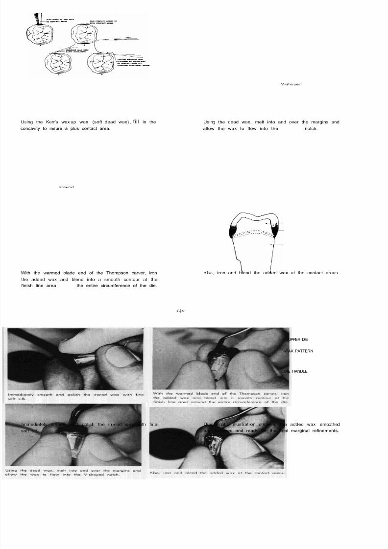
8/11/2019 An Atlas of Cast Gold Procedures
http://slidepdf.com/reader/full/an-atlas-of-cast-gold-procedures 147/270
Using the Kerr's wax-up wax (soft dead wax) , f i l l in the
concavity to insure a plus contact area.
With the warmed blade end of the Thompson carver, iron
the added wax and blend into a smooth contour at the
finish line area around the entire circumference of the die.
Immediately smooth and polish the ironed wax with fine
soft silk.
Using the dead wax, melt into and over the margins and
allow the wax to flow into the V-shaDed notch.
Also, iron and blend the added wax at the contact areas.
COPPER DIE
WAX PATTERN
DIE HANDLE
\
Diagramatic illustration showing the added wax smoothed
and polished and ready for the final marginal refinements.
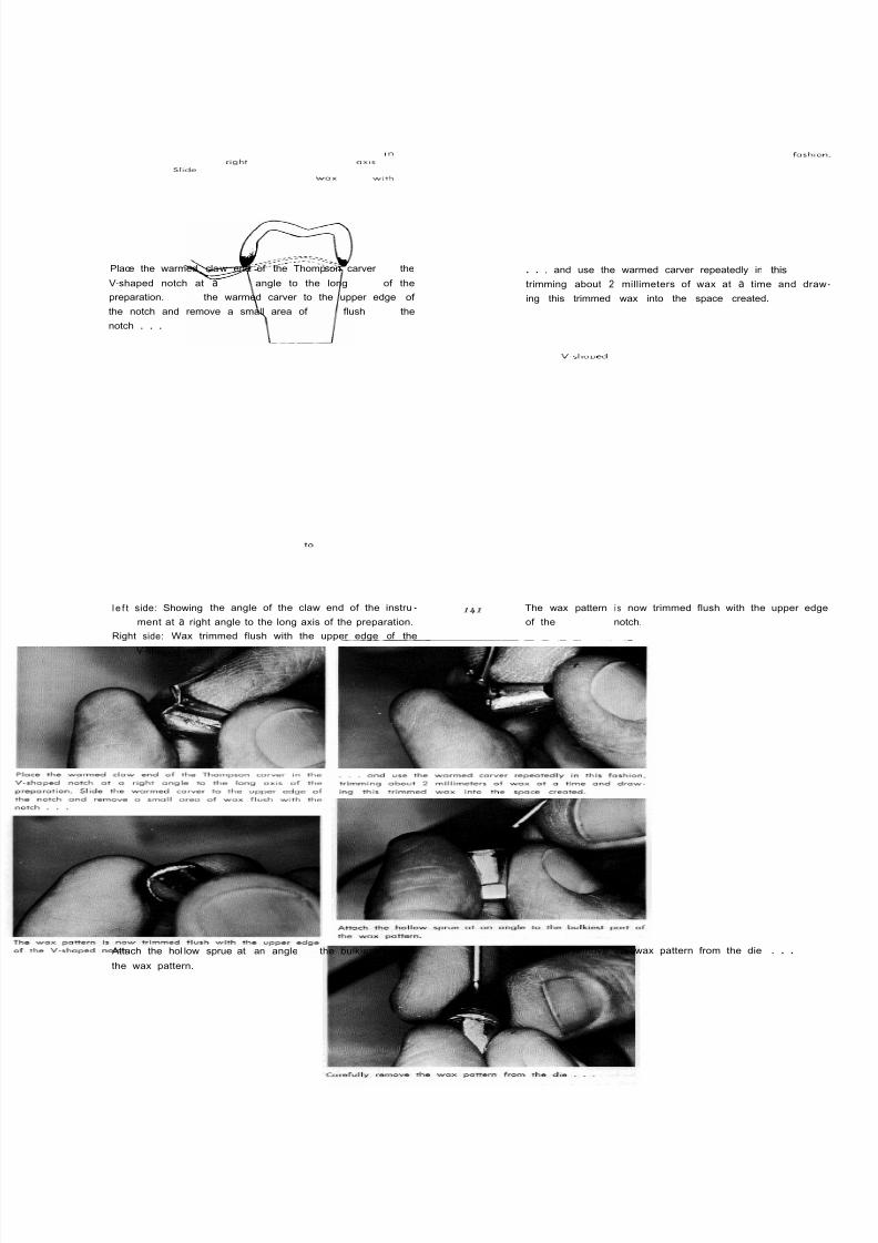
8/11/2019 An Atlas of Cast Gold Procedures
http://slidepdf.com/reader/full/an-atlas-of-cast-gold-procedures 148/270
Place the warmed claw end of the Thompson carver In the
V-shaped notch at a rlght angle to the long axls of the
preparation.Sllde
the warmed carver to the upper edge of
the notch and remove a small area ofwox
flushwlth
the
notch . . .
. . . and use the warmed carver repeatedly in this fashlo
trimming about 2 millimeters of wax at a time and dra
ing this trimmed wax into the space created.
l e f t side: Showing the angle of the claw end of the instru-
ment at a right angle to the long axis of the preparation.
Right side: Wax trimmed flush with the upper edge of the
V-shaped notch.
The wax pattern i s now trimmed flush with the upper edg
of the V-sharJed notch.
Attach the hol low sprue at an angle to the bulkiest part of
the wax pattern.
Carefully remove the wax pattern from the die . . .

8/11/2019 An Atlas of Cast Gold Procedures
http://slidepdf.com/reader/full/an-atlas-of-cast-gold-procedures 149/270
and mount on the crater former Make the sprue I inch long and equal in diameter to the
thickest port of the wax pattern. Mount I 700 plastic pin
(Wilkinson) on the crater formerto
be cast with the crown.
The ring and crater former assembly with the wet asbestos
liner.
From left to right: 50 grams of Baker's scientific casting in -
vestment; dropper bottle of room temperature water; plastic
graduate marked at 12.8 cc.
Place the 50 gms. of investment in the mixing bowl and
then add the 12.8 cc. of water.
Vacuum mix the investment, along with heavy vibration, for
75 seconds.

8/11/2019 An Atlas of Cast Gold Procedures
http://slidepdf.com/reader/full/an-atlas-of-cast-gold-procedures 150/270
Release the vacuum seal and further vibrate the investment
until all air bubbles disappear. This may require an addi -
tional 30 to 40 seconds.
Use mild vibration in filling the ring with investment to
permit the investment to nestle around the pattern.
Support the ring and crater former with the fingers a
slowly fill the ring with the investment.
Completely immerse the fil led ring in a 100' F. wa
bath and al low to remain for a minimum of /* hour.
Remove the ring and crater former from the water bath and
allow to bench dry for a minimum of 15 minutes or until
the investment i s hard.
Immerse the crater former and ring in hot water befo
separating.
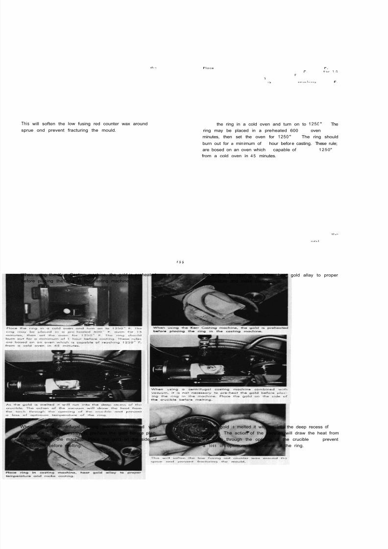
8/11/2019 An Atlas of Cast Gold Procedures
http://slidepdf.com/reader/full/an-atlas-of-cast-gold-procedures 151/270
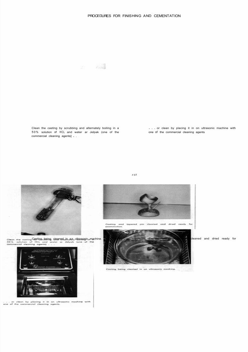
8/11/2019 An Atlas of Cast Gold Procedures
http://slidepdf.com/reader/full/an-atlas-of-cast-gold-procedures 152/270
PROCEDURES FOR FINISHING AND CEMENTATION
Clean the casting by scrubbing and alternately boiling in a
5 0 % solution of HCL and water ar Jelpak (one of the
commercial cleaning agents] . , ,
Casting. being cleaned in an ultrasonic machine.
. . . or clean by placing it in on ultrasonic machine w
one of the commercial cleaning agents.
Casting and tapered pin cleaned and dried ready
examination.

8/11/2019 An Atlas of Cast Gold Procedures
http://slidepdf.com/reader/full/an-atlas-of-cast-gold-procedures 153/270
The tapered pin i s separated from the casting. Any rough-
ness or nodules in the crown costing are removed with o
small round bur. The stripping rod i s grasped with the black
or cathode clip while the casting i s being held with the red
or anode clip. The crown i s filled with the hot stripping
solution and the stripping rod is held inside the crown. In
this monner you may strip up to 50 seconds ot 10-second
intervals. It is tried for fit between each interval.
I +DIE H ANDLE
I':Seat the etched casting on the
master
die. When properly
seated the margins of the casting will line up exactly flush
with the upper edge of the prepared notch.
The casting is being held by the anode clip ready for over -
all stripping in the stripping unit. In occasional instances on
additional 20 seconds of over -all stripping may be desiroble
followlng the inside stripping.
After the casting i s seated, gradually reduce the 1/4 mill i-
meter excess gold to '/8 millimeter using the cup-shaped car-
borundum disc. This i s accomplished while mointaining the
desiredcemento-enamel
contour.
Diagram shows proper angulation of the cup-shaped io-dandy
disc, A port ion of the die i s cut along with the gold at the
mm. excess is reduced to /*
mm. The final adjustment of
the gingival overlap should be accomplished with the casting
removed from the die.
Smooth the surface of the gold with a Burlew wheel.
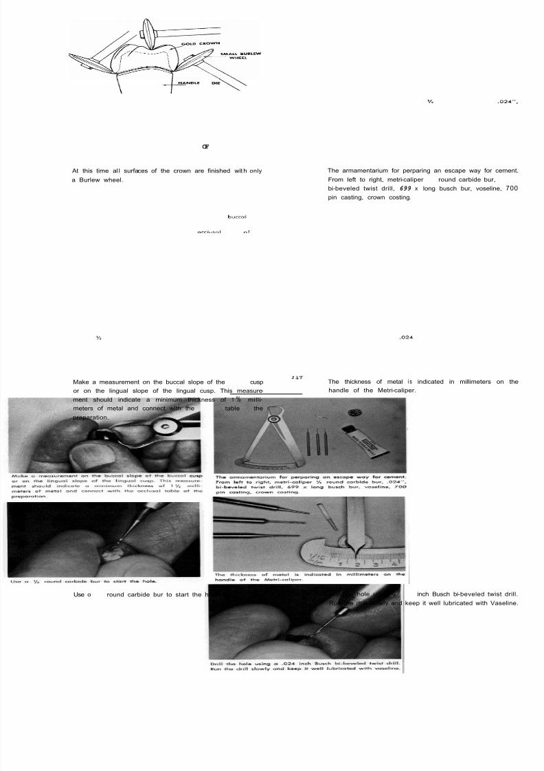
8/11/2019 An Atlas of Cast Gold Procedures
http://slidepdf.com/reader/full/an-atlas-of-cast-gold-procedures 154/270
\
F D L E
OF DE
At this time al l surfaces of the crown are finished with only
a Burlew wheel.
The armamentarium for perparing an escape way for ceme
From left to right, metri -caliper round carbide bur, .02
bi-beveled twist drill, 699 x long busch bur, voseline, 7
pin casting, crown costing.
Make a measurement on the buccal slope of the buccal cusp
or on the lingual slope of the lingual cusp. This measure -
ment should indicate a minimum thickness of 1 % milli-
meters of metal and connect with the OCCIUSOItable of the
preparation.
The thickness of metal i s indicated in millimeters on
handle of the Metri-caliper.
Use o round carbide bur to start the hole. Drill the hole using o .024 inch Busch bi-beveled twist d
Run the drill slowly and keep it well lubricated with Vaseli

8/11/2019 An Atlas of Cast Gold Procedures
http://slidepdf.com/reader/full/an-atlas-of-cast-gold-procedures 155/270
Briefly rotate the 699 long bur in the hole producing a taper. Rotate the tapered pin in the hole two complete turns with
finger pressureto
insure a pressed fit.
Examine the inside of the crown to observe how far the pin
extends beyond the inside thickness o f the crown.
With a 4 round bur, cut the pin a little short of the inside
thickness of the crown to permit the pin to completely seat
when the crown i s cemented. Rotate the pi n in a complete
circle as thisadlustment
i s being made.
Air -erase the casting using a spray bottle containing flour of
pumice. After the contact areas are adiusted and the crown
has been seated, test the occlusion with "Madam Butterfly"
typewriter ribbon.
The contacts of centric occlusion are plainly visible when the
casting has been previously air -erased.

8/11/2019 An Atlas of Cast Gold Procedures
http://slidepdf.com/reader/full/an-atlas-of-cast-gold-procedures 156/270
Test the centric occlusion with 1/ 1000 cellophane placed
between the restoration and the opposing teeth. I f the cello-
phane will tear when on attempt is made to pull it out,
the operator may be assured the restoration is in occlusion.
Make this same test between the teeth anterior to t
restoration . . .
. . and posterior to the restoration . . .
Armamentarium forftntshtng
the costing. From left to right.
small bud bur; Sulci Burlew wheel; Burlew wheel; soft Dtxon
brush; rag wheel; wet pumice; chaulk.
. . . and between the teeth on the opposite side of t
arch. If the cellophane will hold and tear in all of the
positions it may be assumed that the restoration is not hi
and is in favorable centric occlusion.
Accomplish the primary occlusal finish wi th wet pumice a
the Dixon brush. Rubber Burlew wheel may also assist
this procedure.
149
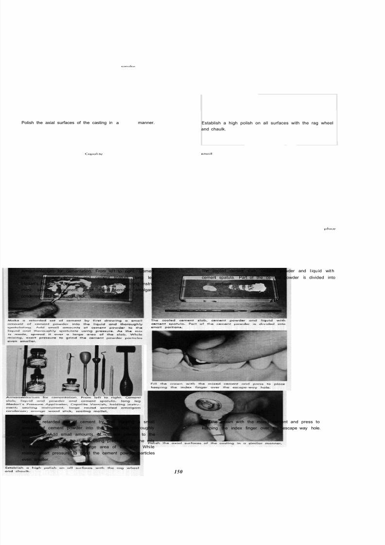
8/11/2019 An Atlas of Cast Gold Procedures
http://slidepdf.com/reader/full/an-atlas-of-cast-gold-procedures 157/270
Polish the axial surfaces of the casting in asimilor
manner.
Armamentar ium for cementation. From lef t to right: Cement
slab; l iqu id and powder and cement spatula; long leg
Medart's Pressure Applicator; Copalite Varnish; holding instru-
ment; seating instrument; large round serrated amalgam
condenser; orange wood stick; seating mallet.
Establish a high polish on all surfaces with the rag wheel
and chaulk.
The cooled cement slab, cement powder and l iqu id with
cement spatula. Part of the cement powder is divided into
smoll portions.
Make a retarded set of cement by first drawing a small
amount of cement powder into the liquid and thoroughly
spatulating. Add small amounts of cement powder to the
liquid and thoroughly spatulate using pressure. As the mix
is made, spread it over a large area of the slab. Whi le
mixing, exert pressure to grind the cement powder particles
even smaller.
F i l l the crown with the mixed cement and press to place
keeping the index finger over the escape-way hole.
150

8/11/2019 An Atlas of Cast Gold Procedures
http://slidepdf.com/reader/full/an-atlas-of-cast-gold-procedures 158/270
Further seat the crown using pressure with mallet force. When the crown i s completely seated, no more cement w
exude from the escape-way hole. Hold the crown in p
sition with the hand holding instrument . . .
. . . or with the Medart 's Pressure Applicator using biti ng
force. While holding this pressure, seat the tapered gold pin
in the hole using the serrated amalgam condenser.
While the cement i s still soft, clip off the gold pin 1 mill
meter above the surface of the crown. Again press it to ploc
with the serrated amalgam condenser. Hold the crown firml
in position during this procedure.
While the cement i s still soft, use a coarse Wet -0-Dry disc to
cut the pin almost flush with the casting. Follow this with a
fine cuttle disc, pumice and chaulk.
151
Completed fu l l veneer finish line crown.

8/11/2019 An Atlas of Cast Gold Procedures
http://slidepdf.com/reader/full/an-atlas-of-cast-gold-procedures 159/270

8/11/2019 An Atlas of Cast Gold Procedures
http://slidepdf.com/reader/full/an-atlas-of-cast-gold-procedures 160/270
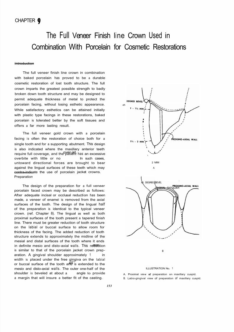
8/11/2019 An Atlas of Cast Gold Procedures
http://slidepdf.com/reader/full/an-atlas-of-cast-gold-procedures 161/270

8/11/2019 An Atlas of Cast Gold Procedures
http://slidepdf.com/reader/full/an-atlas-of-cast-gold-procedures 162/270
The porcelain facing may be fabricated by either
of two methods:
A. Fabrication of Facing From a Denture Tooth
1. Select proper shade and mould of denture
tooth (diatoric or pin type).
2. Reduce pins and hollow grind lingual surface
of facing using a suitable size diamond or
carborundum wheel stone. Ample lubrication
with Vaseline or glycerine will minimize ten-
dency of porcelain to chip or fracture.
ILLUSTRATION No. 2
A. Proximal view of pi n facing.
B. Incisal view of pin facing.
C. Hollow grinding facing with diamond stone.
3. Apply powdered graphite or soft pencil lead
to the labial or buccal surface of the die in
the working model.
4. Position the facing against the working die
and attain internal markings by applying a
slight rubbing motion. Closer adaptation and
axia l alignment of the facing is accomplished
by grinding the indicated areas.
Denture
\I
\...
POSITION OF FACING
ILLUSTRATION No. 3
tooth positioned agoinst die after initial grinding
5. Before obtaining the final axia l alignment
reduce the ridge-lap portion of the facing to
approximate the position of the gingiva
shoulder of the die. At the same time adjus
the incisal or occlusal length of the facing to
approximately the desired clearance.
ILLUSTRATION No. 4
Approximate axial, gingival and incisa l ali gnment of facing
after reduction of gingival and incisal portions of facing
6. Obtain final axial alignment by careful mark
ing and hollow grinding.
7. Secure facing in position with a small amoun
of sticky wax and make a plaster core on the
labial or buccal surface of the working mode
to hold the facing in place. Trim the plaste
core one to two millimeters short of the incisa
or occlusal edge of the facing.

8/11/2019 An Atlas of Cast Gold Procedures
http://slidepdf.com/reader/full/an-atlas-of-cast-gold-procedures 163/270
PLASTER CORE\ FACING-,
DRILL PRESS BASE
A
B
8.
9.
10.
A
Qc
WING AREA OF FACING
B
A. Proximal view of retention wings.
B. Incisal view of retention wings.
B
A VariationILLUSTRATION No. 5
Incisal view of plaster core
Proximal view of plaster core.
Hold the facing in position with the plaster
core and adjust the length of the incisal or
occlusal edge to provide approximately mm.
clearance.
Adjust the gingival wal l of the facing to permit
?4 mm. clearance for gold. The gingival and
incisal or occlusal walls of the facing must
have a slight taper in the lingual direction to
allow withdrawal of the facing from the wax
pattern and to permit reseating the facing into
the casting. Excessive taper of the gingival
and the incisal or occlusal walls of the facing
will reduce its retention in the casting.
The mesial and distal portions of the facing
extend well into the proximal embrasures. This
extension prevents display of gold and pro-
vides sufficient porcelain for the shaping of
retention wings. The retention wings are
tapered in such a manner that they will extend
into a recess of the casting.
When added retention is necessary to retain
the facing in the casting, the ends of the wings
may be flattened to permit the drilling of small
holes .022 inch in diameter.
ILLUSTRATION No. 7
Facing mounted in drill press.
155

8/11/2019 An Atlas of Cast Gold Procedures
http://slidepdf.com/reader/full/an-atlas-of-cast-gold-procedures 164/270
Nylon bristles 020 inch in diameter are fitted
into these holes. The end of the bristle must
extend slightly beyond the facing to permit
firm attachment to the wax pattern.
A
PIN HOLES WITH NYLONBRISTLES IN PLACE
B
ILLUSTRATIONNO
a
A. Proximal view of pin holes.
B. Incisal view of pin holes.
These small pins become part of the casting
and afford much greater retention for the
porceIa in facing.
11. In the final refinement of the margins of the
facing, make certain that any sharp angles are
removed. However, all cavo-surface margins
should be sharp and definite to facilitate wax-
ing the pattern and dressing the gold to the
porcelain in the final fitting of the casting.
Adequate incisal or occlusal coverage of the
porcelain with gold is necessary to prevent
injury to the facing.
12. Warm the working model, die, facing, and
plaster core by placing in hot water. Lubricate
the warmed facing and die. With the facing
positioned inside the plaster core, drop molten
wax onto i t s internal surface and immediately
position the core and facing onto the working
model. Now flow wax onto the remainin
surfaces of the die to establish the final con
tour of the wax pattern. Establish the fina
adaptation of the margins using Kerr's Wax
up wax.
13. Use a piece of sticky wax to remove the facin
from the wax pattern.
STICKY WAX
ILLUSTRATION No. 9
Removing facing from wax pattern with sticky wax.
14. Attach a hollow sprue to the center of the wa
pattern just gingival to the incisal edge.
ILLUSTRATION No. 10
Sprue attached to wax pattern.
15. Carefully remove the wax pattern, invest, burn
out and cast. After the casting is made i
should be thoroughly cleansed and etched be
fore attempting to fit the facing into the win-
dow of the casting.
156

8/11/2019 An Atlas of Cast Gold Procedures
http://slidepdf.com/reader/full/an-atlas-of-cast-gold-procedures 165/270
B. Fabrication of Facing Using a Modification of the PORCELAIN FUSED ONTO VENEER CASTINGS
Hagen Technique*
1 . Wax the crown to full contour on the working
model.
2. Cut a labial window in the wax with sufficient
extension of i ts margins in a l l directions to
minimize the display of gold. This will provide
adequate room for porcelain in the proximal
areas to permit the designing of retention
wings on the porcelain facing.
3. In establishing the window, leave a layer of
wax approximately 0.2 mm. thick over the
labial surface of the die.
4. Make an impression of the labial surface of
the wax pattern and its window using rubber
base impression material. From this impression
fabricate a stone or electroplated die.
5. Adapt plat inum foil to the die and fabricate
a porcelain facing to fit the labial window. The
procedures of opaquing, building, condensing,
and fusing the porcelain are similar to those
used in making a porcelain inlay.
6. Try the porcelain facing into the window of
the waxed crown.
7. Prepare the mesial and distal wings of the
facing to minimize the display of gold and to
provide for retention as described under tech-
nique A. Where added retention is needed,
flatten the ends of the wings to permit drilling
small diameter holes as described in tech-
nique A.
8. Make al l cavo-surface margins of the facing
continuous and remove any sharp angles which
might tend to result in fracture of the facing.
9. Fit nylon bristles to the holes and complete
the wax-up of the crown.
10. Use a piece of sticky w a x to remove the
facing from the wax pattern.
11 . Attach a hollow sprue to the center of the
wax pattern jus t gingival to the incisal edge.
12. Carefully remove the wax pattern, invest,
burn-out and cast. After the casting is made it
should be thoroughly cleansed and etched
before attempting to fit the facing into the
window of the casting.
Excellent esthetics can be attained by either
technique.
* I W. H. 8 Hagen; Comb ina t ion Gold and Porcelain Crown;
J . Pros. Dentistry, 10:325-329,1960.
Introduction
In recent years specially fabricated porcelains
and high-fusing alloys have been developed that can
be successfully bonded. These esthetic, durable restora-
tions can be utilized for individual crowns, supporting
abutments, and bridge pontics. A number of such
materials are available. The restorations may be de -signed in several ways. The porcelain may cover the
greater portion of the crown or it may be baked into
a prepared window. "The baked in" facing technique
is particularly advantageous for posterior restorations
where it is desirable to maintain the occlusal contacting
surfaces in metal. To establish color compatibility with
other gold restorations in the mouth, the exposed metal
surfaces may be gold plated. The gold plating process
can be easily accomplished by using a stripping unit
(refer Chapter 7) in a reverse procedure. An ingot
of 22-karat casting gold is grasped in the anode clip
and immersed in the cyanide solution. The bridge or
restoartion to be plated is grasped in the cathode cl ipand immersed in the solution. The thickness of the gold
plate deposited will depend upon the time factor. The
internal surfaces and the margins of the casting can
be protected against plating provided the temperature
of the solution is not elevated too high.
I
I
0.2 - 0.5 MM
GOLD ALLOY
BONDED PORCELAIN
A
\ i
B
ILLUSTRATION No. 1 1
A. Design of restoration wi th par tia l coverage of porcelain.
B. "Baked in facing" design wi th occlusal established i n metal.

8/11/2019 An Atlas of Cast Gold Procedures
http://slidepdf.com/reader/full/an-atlas-of-cast-gold-procedures 166/270
Preparation
The design of the preparation is the same as for
a full veneer gold crown with a porcelain facing
fabricated from a denture tooth. (Page 153, Illustra-
tion No. 1)
A tapered-barrel shaped diamond stone with a
rounded end is used to reduce enamel on the labial
and lingual aspect of the tooth. The gingival finish
line is initially established at approximately the height
of the gingival crest. A small diameter flame shaped
diamond stone is employed to establish the inter -
proximal finish line which is continuous with the
champered finish lines of the labio or bucco-gingival
and linguo-gingival surfaces of the tooth. There should
be approximately 2mm of reduction of tooth structure
incisally or occlusally. One and one-half millimeters
reduction is necessary on the labial or buccal and
interproximal surfaces where the porcelain veneer
is to be added. The metal of the casting in these areas
should be approximately 0.2 to 0.5 mm in thickness.
A small diameter tapered carbide bur is now
used to establish a gingival shoulder approximatelyl m m wide at the level or slightly below the gingival
crest. The shoulder is extended well into the inter -
proximal regions and ends in definite mesio and
disto-axial walls. Before extending the final finish
ILLUSTRATION No. 12
Establish the labio or bucco-gingival finish line with a tapering
barrel-shaped diamond. A small diameter flame -shaped didmond
stone i s used to establish the interproximal finish line.
A small diameter tapered carbide bur is used to establish a gin -
gival shoulder. The shoulder i s extended well into the intro-
proximal region.
A small tightly wrapped strand of cotton yarn i s tucked beneath
the gingival. This i s covered with a larger strand of cotton which
is tucked tightly over the smaller strand. This remains until suffi -
cient retraction i s obtained to protect the tissue to be retracted.
The outer one -half of the shoulder i s beveled at about a 45O
angle with a short flame-shaped diamond.
158
line of the preparation well beneath the crest of th
free gingiva it i s recommended that tissue be now
retracted. A small tightly wrapped strand of cotto
yarn i s tucked beneath the gingiva. This is covere
with a larger strand of cotton which is tucked tightl
over the smaller strand as a pressure pack. Bot
strands of cotton remain in position for a sufficien
length of time to prevent injury of the gingivalcres
during final instrumentation. The larger strand of yar
is removed and the outer one-half of the shoulder ibeveled at about a 45 angle with a short flame
shaped diamond stone.
The purpose of the gingival shoulder and axia
walls i s to provide bulk of metal in strategic areas o
the casting. These areas of increased thickness act a
buttresses to resist distortion of the casting due to
dimentional changes of the porcelain veneer durin
firing.
Waxing
Patterns should be waxed to a minimum thickne
of 0.2 to 0.5 mm. in the areas to be covered w
porcelain. Sharp angles should also be avoided
these areas. Special attention must be directed towa
accurate adaptation of the wax to the finish line of th
preparation. This procedure is difficult since the bu
or thickness of wax in the region of the finish line
much thinner than for the typical veneer crown.
10-gauge sprue should be used to secure the patte
to the crucible former.
Investina. Castina and Treatment of the Casting
Specially formulated investments must be use
with higher melting point alloys to produce accura
castings. The manufacturer's instructions should b
specifically followed when using these products. An
changes in the alloys either by contamination or mi
handling may lead to ultimate failure. Ordinary go
alloys do not have linear coefficients of expansion
melting temperatures which are compatible with th
coefficient of expansion and fusing temperature
porcelain. The special alloys employed are formulate
to provide a coefficient of linear expansion which
compatible with that of the special porcelain (1.45%
Essentially the copper content of regular gold alloy
replaced w i t h increased percentages of platinum
palladium, and very small percentages of other el
ments. The purposes of re-alloying are to raise th
melting point of the casting gold (to approximate
2250" F.) sufficiently above the fusing temperature
the special porcelains (approximately 1850 " F.) and
establish the same coefficient of linear expansion
the porcelain.
The porcelains compounded for this purpos
contain 70+ silica which i s necessary to establis
the desired linear coefficient of expansion of 1.45%
8/11/2019 An Atlas of Cast Gold Procedures
http://slidepdf.com/reader/full/an-atlas-of-cast-gold-procedures 167/270
The metal should always be melted in a crucible
used exclusively for this purpose to avoid contamina-
tion from undesirable elements contained in ordinary
cast gold alloys. Excessive casting pressure will cause
breakdown of the investment with resulting roughness
on the surfaces of the casting. For this reason it is
advisable to use a minimum number of turns with
centrifugal casting machines. Excessive and prolonged
heating of the metal in the crucible should be avoided.
After the casting is made and thoroughly cleansed,
i t i s lightly etched mechanically and fitted to the
prepared tooth. There are definite advantages to
adjusting the casting in the mouth before the porcelain
is baked onto the metal. This makes it possible to
determine the fit at the gingival finish line of the
preparation more accurately. Also, adjustments and
complete seating of the casting can be accomplished
without danger of injuring the thin overlay of porcelain
near the gingival margins. If the initial seating onto
the tooth is done after the porcelain is baked on,
injury to the porcelain will sometimes occur in this area.
It has been an accepted procedure to place the
casting in hydrofluoric acid for a number of hours
before the bake on process is begun. The acid bath
eliminates organic materials and occluded gases which
might cause porosity in the porcelain. Following the
acid treatment, pliers should be used in handling the
casting to avoid additional contamination.
Gold Coating the Surfaces of the Casting.
It is a consensus of opinion that bonding porcelain
onto metal is greatly enhanced by fusing or soldering
a thin coat of pure gold onto the specificd surfaces of
the casting. First, carborundum stones are used to
remove any sharp corners or edges of the casting
which might induce fracture lines in the porcelain and
to produce a clean surface free from oxides and con-
tamination. A preparation of finely divided pure gold
and s i l ica flux in a glycerine vehicle is painted onto the
freshened surfaces of the casting. The casting is placed
into a porcelain oven and the temperature is elevated
to the melting point of pure gold (1945 " F.) to com-
plete the soldering process. While the casting is still
heated it is plunged into water to explode the si l ica
flux off of the pure gold surface. Complete removal
of the flux particles i s accomplished by warming thecasting and immersing it in a 50% solution of hydro-
chloric acid several times. The casting is now ready for
the application of porcelain.
Applying and Firing the Porcelain
There are three materials used for building the
veneer of porcelain onto the gold casting:
1 ) Opaque porcelain
2) Gingival porcelain
3) Incisal porcelain
The opaque porcelain serves a two -fold purpose.
ts principle function is to mask out the color of the
underlying gold. Its fusing property is primarily re-
sponsible for bonding the porcelain to the metal. The
bonding of porcelain to metal is primarily accomplished
by a "compression mechanism" of the porcelain as it
changes from a liquid to a solid state. As the porcelain
sets, extreme forces of compression lock the mass into
and around any irregularities even of a microscopic
dimension. One of the most accepted theories main-
tains that a n infinite number of misce1ls or microscopic
pockets attach themselves to the metal as the mask
cools creating minute vacuum chambers that aid in
locking the porcelain onto the metal surface.
The gingival porcelain provides the body shade
which can be altered with modifiers. The incisal shade
provides the translucency of the incisal edge. After
the metal has been completely opaqued, the building
and firing of the balance of the porcelain is accom-
plished in a manner similar to that used in fabricating
a porcelain jacket crown. It should be pointed out that
cleanliness in porcelain procedures cannot be over -
emphasized. The hands, instruments, and working area
should be free from contamination. The porcelain
should be built to excess contour and fired to a biscuit
bake. The margins and details of anatomy are refined
at this time by selective grinding. A final glaze is
established by employing a controlled technique of
firing time and temperature. Porcelain stains can be
employed for further characterizing of the porcelain,
It shDuld be emphasized that vacuum firing is im-
Fmtant in achieving color stability during the firing
process. Strict adherence to the manufacturer's rec-
ommendations as to the firing cycle is mandatory forthe best esthetic results.
"Bake on" porcelains are now being compounded
which are fused at a temperature considerably higher
(2300-2400" F.) than that used in producing the present
"fritted" porcelains (1 400-1500" F.). In the initial firing
of these products at high temperatures they become
true porcelains instead of "fritts" (glass compounds)
before being ground and prepared for dispensing.
Essentially the higher range of firing in the manufac-
ture of porcelain products eliminates gases and organic
m a t e r i a I. This method of manufacture produces
porcelains which have higher density and greatertranslucency. Improvements are also being made in
the color stability of porcelains by utilizing higher
fusing metallic oxides in the place of less stable
products. No doubt rapid improvements will continue
to be made in the manufacture and techniques em-
ployed with these widely used products.
Porcelain fused onto cast gold restorations satisfies
a real need in modern restorative treatment. Careful
diagnosis will determine the conditions under which
this type of restoration is indicated.
159

8/11/2019 An Atlas of Cast Gold Procedures
http://slidepdf.com/reader/full/an-atlas-of-cast-gold-procedures 168/270

8/11/2019 An Atlas of Cast Gold Procedures
http://slidepdf.com/reader/full/an-atlas-of-cast-gold-procedures 169/270
TOP PLATE
Mixing heavy-bodied elasticon.
BOTTOM PLATE
Full veneer crown impression, using controlled tube
technique.

8/11/2019 An Atlas of Cast Gold Procedures
http://slidepdf.com/reader/full/an-atlas-of-cast-gold-procedures 170/270
CHAPTER 1
The Three-Quarter Crown and
Other Partial Veneer Crown Restorations
Introduction
The advantages and application of the veneer
principle in the restoration of lost tooth structure has
been discussed in Chapter No. 8 on the full veneer
finish line crown restoration.
One of the principle indications for the three-
quarter veneer crown type of restoration i s in those
instances where there has been considerable destruc-
tion of tooth structure but with the labia l or buccal
surface of the tooth remaining intact. In these instances,
the veneer principle will impart maximum strength tothe remaining tooth structure. As a secondary consider -
ation, the veneer three-quarter crown design permits
obtaining adequate retention and resistance form for
the restoration with a minimum display of gold. Also,
a frequent indication is the restoration of anterior teeth
with limited mesial and distal involvement and with
lingual erosion and abrasion. The three-quarter veneer
crown design can be used to good advantage where
re-contouring of the tooth crown is necessary for the
purpose of re-establishing the loss of contact with
adjacent teeth and re-shaping proximal embrasures.
Another indication is the re-establishment of lost
vertical dimension. The resistance and retention formprovided by the three-quarter crown design is ideal
for splinting teeth in instances where there is consider -
able mobility. Also, added retention is necessary for
single or multiple abutments for either fixed or
removable prosthodontic restorations.
Fundamental Principles of Design
The primary objectives of the three-quarter veneer
1) To impart strength to the remaining portion
of the tooth crown.
2) To provide maximum resistance and retention
form to the finished restoration.
3) To establish a favorable line of shed.
4) To preserve esthetics by conservation of tooth
structure, thus limiting the display of gold
on buccal and labial surfaces.
crown restoration are:
Outline Form
When skillfully designed, there need be little or
no display of gold to detract from the esthetic appear -
ance of the restoration. The proximal extensions for
both anterior and posterior teeth can be placed within
labial or buccal embrasures in such a manner that they
will be largely hidden from view. The axial angles of
the tooth should be preserved both for the conserva-
tion of tooth structure and for the best esthetic results.
The proximal extensions of three-quarter crown
restorations on the mesial surfaces of the teeth should,
wherever possible, be confined to a minimum for the
cosmetic effect. The proximal extensions on the distal
surfaces of the teeth can be extended to provide a
more favorable line of shed. Also, by grasping a
slightly greater convexity of the tooth, the casting will
have more retention. (See Illustration No. 1)Interproximal clearance and extensions of the
preparation can be attained by penetrating either a
portion or al l of the enamel. This will result in a
dofinite gingival finish line on the proximal surfaces
of the preparation. This finish line should be carried
slightly below the crest of normal interseptal gingival
tissue. However, in the presence of excessive gingival
recession, it may be desirable to leave the finish line
above the gingival crest to prevent the excessive
removal of tooth structure. The gingival finish lines
on the mesial and distal surfaces of the tooth are
connected by the lingual finish line of the preparation.
Particularly in the instance of anterior teeth, the lingual
finish line is extended under the free gingiva for
protection against recurrence of caries and also to
provide the greatest axial length to the cingulum wall
of the preparation for retention. (See Illustration No. 1 )
The incisal edges of the anterior teeth and the
crest of the buccal cusps of the posterior teeth must
be covered with a veneer of gold to prevent injury
to these more vulnerable tooth surfaces. Usually, a
reduction of approximately'/2
to 1 millimeter of tooth
structure will provide a sufficient bulk of gold to
withstand forces of mastication and protect these
fragile margins from injury. (See Illustration No. 1)Resistance and Retention Form
The placement of grooves in the proximal areas
of the preparation is a critical factor in establishing
both a favorable line of shed and obtaining maximum
retention and resistance form in the finished restora-
tion. These retention grooves should be placed in a
direction and relationship to the l a b i a l or buccal
extension of the preparation which will provide the
longest possible retentive groove without undermining
the labio-incisal or bucco-occlusal area of enamel. The
161
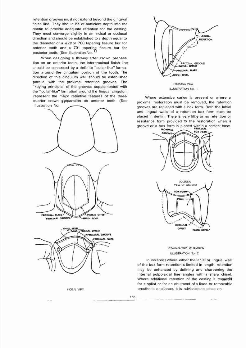
8/11/2019 An Atlas of Cast Gold Procedures
http://slidepdf.com/reader/full/an-atlas-of-cast-gold-procedures 171/270
retention grooves must not extend beyond the ging ival
finish line. They should be of sufficient depth into the
dentin to provide adequate retention for the casting.
They must converge slightly in an incisal or occlusal
direction and should be established to a depth equal to
the diameter of a 699 or 700 tapering fissure bur for
anterior teeth and a 701 tapering fissure bur for
posterior teeth. (See Illustration No. 1)
When designing a threequarter crown prepara-
tion on an anterior tooth, the interproximal finish line
should be connected by a definite "collar -like" forma-
tion around the cingulum portion of the tooth. The
direction of this cingulum wall should be established
parallel with the proximal retention grooves. The
"keying principle" of the grooves supplemented with
the "collar -like" formation around the lingual cingulum
represent the major retentive features of the three-
quarter crown preparation on anterior teeth. (See
Illustration No. 1
LABIAL VIEW
LINGUAL VIEW
INCISAL VIEW
PROXIMAL GROOVE
PROXIMAL VIEW
ILLUSTRATION No. 1
Where extensive caries is present or where a
proximal restoration must be removed, the retention
grooves are replaced with a box form. Both the labia
and lingual walls of a retention box form must be
placed in dentin. There is very little or no retention o
resistance form provided to the restoration when agroove or a box form is placed within a cement base
OCCLUSALVIEW OF BICUSPID
PROXIMAL VIEW OF BICUSPID
ILLUSTRATION No. 2
In instances where either the labial or lingual wa
of the box form retention is limited in length, retentio
may be enhanced by defining and sharpening th
internal pulpo-axial line angles with a sharp chise
Where additional retention of the casting is require
for a splint or for an abutment of a fixed or removabl
prosthetic appliance, it is advisable to place anadd
162
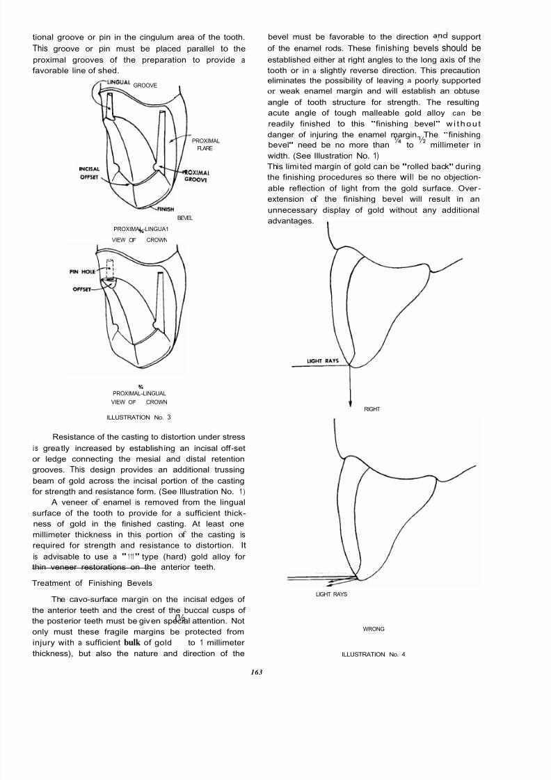
8/11/2019 An Atlas of Cast Gold Procedures
http://slidepdf.com/reader/full/an-atlas-of-cast-gold-procedures 172/270
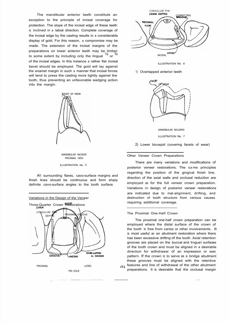
8/11/2019 An Atlas of Cast Gold Procedures
http://slidepdf.com/reader/full/an-atlas-of-cast-gold-procedures 173/270
The mandibular anterior teeth constitute an
exception to the principle of incisal coverage for
protection. The slope of the incisal edge of these teeth
is inclined in a labial direction. Complete coverage of
the incisal edge by the casting results in a considerable
display of gold. For this reason, a compromise may be
made. The extension of the incisal margins of the
preparations on lower anterior teeth may be limited
to some extent by including only the lingual Y or?4
of the incisal edges. In this instance a rather flat incisal
bevel should be employed. The gold will lay against
the enamel margin in such a manner that incisal forces
will tend to press the casting more tightly against the
tooth, thus preventing an unfavorable wedging action
into the margin.
FACET OF WEARI
MANDIBULAR INCISOR
PROXIMAL VIEW
ILLUSTRATION No. 5
Al l surrounding flares, cavo-surface margins and
finish lines should be continuous and form sharp
definite cavo-surface angles to the tooth surface.
Variations in the Design of the Veneer
Three-Quarter Crown Restorations
CINGULUM PIN SHORT
3MM DEPTH)PROXIMAL GROOVE
PROXIMAL G R O O V ~ LNCISALLATER.
PIN HOLE
CINGULUM PIN
3MM DEPTH) CONNECTING
INCISALOFFSET’
ILLUSTRATION No. 6
1) Overlapped anterior teeth
,FACET OF WEAR
MANDIBULAR BICUSPID
ILLUSTRATION No. 7
2) Lower bicuspid (covering facets of wear)
Other Veneer Crown Preparations
There are many variations and modifications o
posterior veneer restorations. The s a me principle
regarding the position of the gingival finish line
direction of the axial walls and occlusal reduction ar
employed as for the full veneer crown preparation
Variations in design of posterior veneer restoration
are indicated due to mal -alignment, drifting, an
destruction of tooth structure from various cause
requiring additional coverage.
The Proximal One-Half Crown
The proximal one-half crown preparation can b
employed where the distal surface of the crown o
the tooth is free from caries or other involvements.
is most useful as an abutment restoration where ther
has been excessive drifting of the tooth. Axial retentio
grooves are placed on the buccal and lingual surface
of the tooth crown and must be aligned in a desirab
direction for withdrawal of an impression or wa
pattern. If the crown is to serve as a bridge abutmen
these grooves must be aligned with the retentiv
features and line of withdrawal of the other abutmen
preparations. It is desirable that the occlusal margi

8/11/2019 An Atlas of Cast Gold Procedures
http://slidepdf.com/reader/full/an-atlas-of-cast-gold-procedures 174/270

8/11/2019 An Atlas of Cast Gold Procedures
http://slidepdf.com/reader/full/an-atlas-of-cast-gold-procedures 175/270
ARMAMENTARIUM FOR THREE-QUARTER CROWN AND
OTHER PARTIAL VENEER CROWN RESTORATIONS
PREPARATION
TAPERED WEDGE
699 TAPERING FISSURE BUR
700 TAPERING FISSURE BUR
'/z ROUND CARBIDE BUR
9 MM. SAFE SIDE DIAMOND DISC
LIGHTNING STRIP
LIGHTNING DISC
MEDIUM SIZE ROUND END TAPERED DIAMOND STONE
MEDIUM SIZE FLAME SHAPE DIAMOND STONE
SMALL DOUGHNUT SHAPE DIAMOND STONE
MEDIUM SIZE CORK SHAPE DIAMOND STONE
WHITE POLY STONE
MEDIUM SIZE TAPERED SQUARE END DIAMOND STONE
. 0 2 8 INCH BI-BEVEL TWIST DRILL
, 0 2 4 INCH 81-BEVEL TWIST DRILL
IMPREWON
HYDROCOLLOID IMPRESSION MATERIAL AND ACCESSORIES
(ref. Chapter 4 )
RUBBER BASE IMPRESSION MATERIAL AND ACCESSORIES
ALGINATE IMPRESSION MATERIAL (TEMPORIZING)
NYLON BRISTLES, . 0 2 8 INCH, . 0 2 7 INCH, . 0 2 6 INCH, . 0 2 4 INCH,
. 0 2 2 INCH, . 0 2 0 INCH
SINGLE EDGE RAZOR BLADE
SPECIAL BRISTLE PLIERS (Engelhardt)
COLD CURE PLASTIC (TEMPORIZING)
ZINC-OXIDE EUGENOL CEMENT
STONE MODELS AND WAXING (refer chanter 51
INVESTING AND CASTING refer chapter 6)
FINISHING AND CEMENTATION (refer chapter 7)
SPECIAL INSTRUMENTS FOR FINISHING
SPRAY BOTTLE WITH FINE FLOUR OF PUMICE
2 ROUND BUR
LENTULO 4 PASTE FILLER

8/11/2019 An Atlas of Cast Gold Procedures
http://slidepdf.com/reader/full/an-atlas-of-cast-gold-procedures 176/270
PROCEDURES FOR PREPARATION OF THE THREE-QUARTER CROWN
Separate teeth with wedge and free contact with a lightning
strip for introduction of lightning disc
Place lightning disc at the proper position and angula-
tion . . .
and make the mesial opening flare. Place the lightning disc at the proper position and angula -
tion . . .
and make the distal opening flare. Mesial and distal opening flares.
167
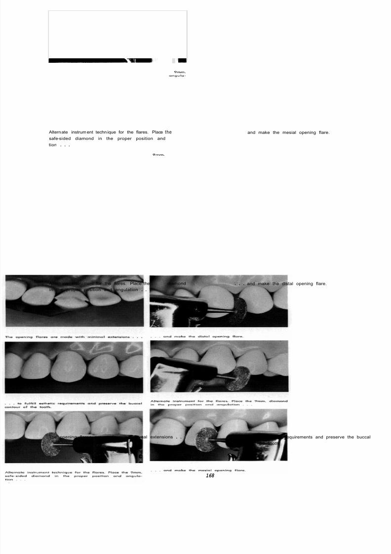
8/11/2019 An Atlas of Cast Gold Procedures
http://slidepdf.com/reader/full/an-atlas-of-cast-gold-procedures 177/270

8/11/2019 An Atlas of Cast Gold Procedures
http://slidepdf.com/reader/full/an-atlas-of-cast-gold-procedures 178/270
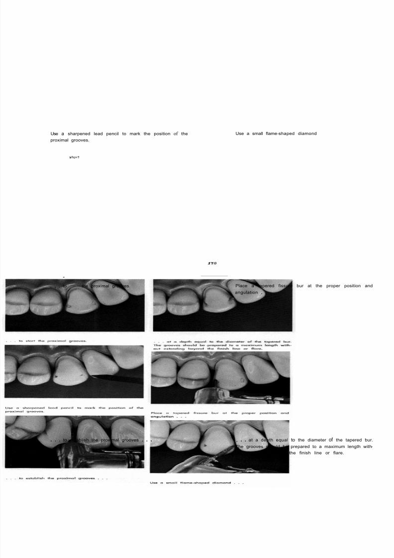
8/11/2019 An Atlas of Cast Gold Procedures
http://slidepdf.com/reader/full/an-atlas-of-cast-gold-procedures 179/270
Use a sharpened lead pencil to mark the position of the
proximal grooves.
Use a small flame-shaped diamond
. . . to start the proximal grooves. Place a tapered fissure bur at the proper position a
angulation . . .
. . . to establish the proximal grooves . . . , . . at a depth equal to the diameter of the tapered b
The grooves should be prepared to a maximum length wit
out extending beyond the finish line or flare.
170
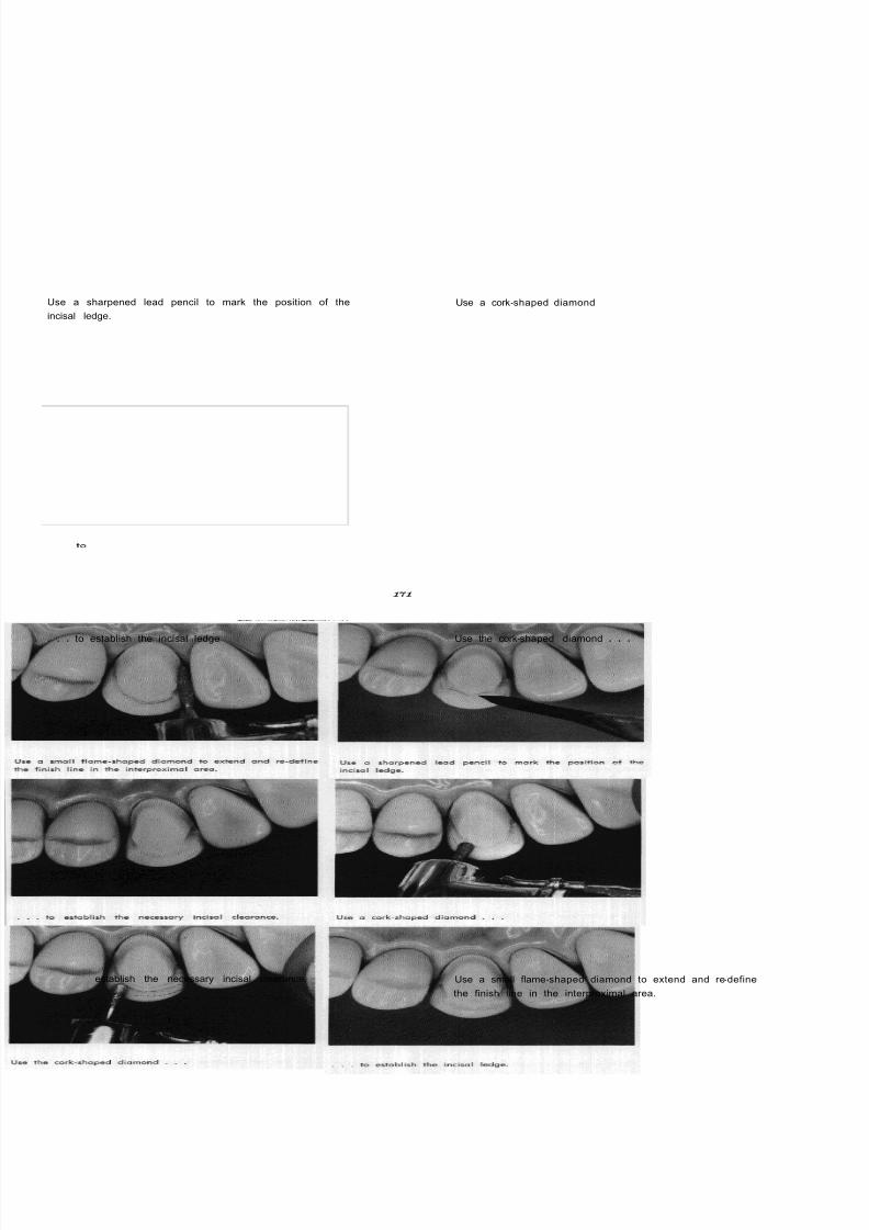
8/11/2019 An Atlas of Cast Gold Procedures
http://slidepdf.com/reader/full/an-atlas-of-cast-gold-procedures 180/270
Use a sharpened lead pencil to mark the position of the
incisal ledge.
Use a cork-shaped diamond
. . . to establish the incisal ledge
to
establish the necessary incisal clearance.
Use the cork-shaped diamond . . .
Use a small flame-shaped diamond to extend and re-define
the finish line in the interproximal area.
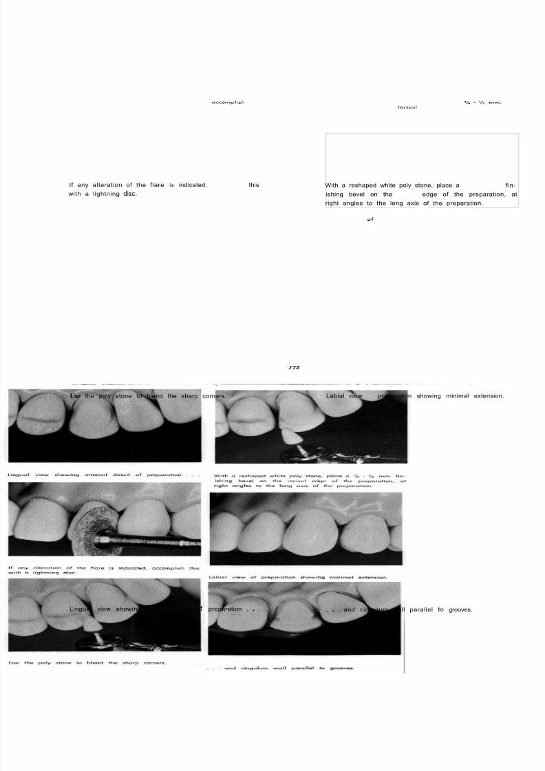
8/11/2019 An Atlas of Cast Gold Procedures
http://slidepdf.com/reader/full/an-atlas-of-cast-gold-procedures 181/270
If any alteration of the flare i s indicated, occomplish this
with a lightning disc.
Use the poly stone to blend the sharp corners.
With a reshaped white poly stone, place a - mm. fi
ishing bevel on the incisol edge of the preparation,
right angles to the long axis of the preparation.
Labial view of preparation showing minimal extension.
Lingual view showing internal detail of preparation . . . . . . and cingulum wall parallel to grooves.
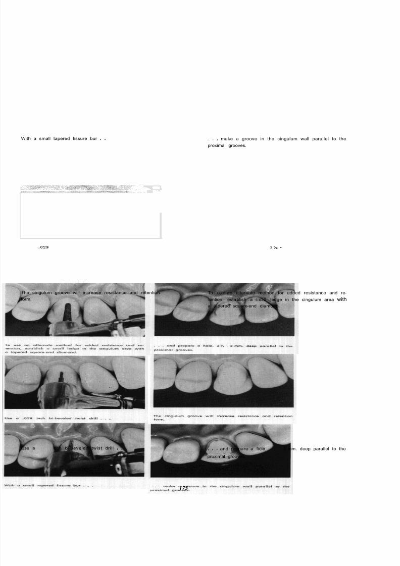
8/11/2019 An Atlas of Cast Gold Procedures
http://slidepdf.com/reader/full/an-atlas-of-cast-gold-procedures 182/270
With a small tapered fissure bur . . . . . make a groove in the cingulum wall parallel to the
proximal grooves.
The cingulum groove will increase resistance and retention
form.
Use a 028 inch bi-beveled twist drill . . .
To use an alternate method for added resistance and re-
tention, establish a small ledge in the cingulum area with
a tapered square-end diamond.
. . . and prepare a hole, 2 3 mm. deep parallel to the
proximal grooves.
173
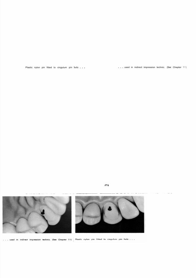
8/11/2019 An Atlas of Cast Gold Procedures
http://slidepdf.com/reader/full/an-atlas-of-cast-gold-procedures 183/270
Plastic nylon pin fitted to cingulum pin hole . . . . . . used in indirect impression technic. (See Chapter
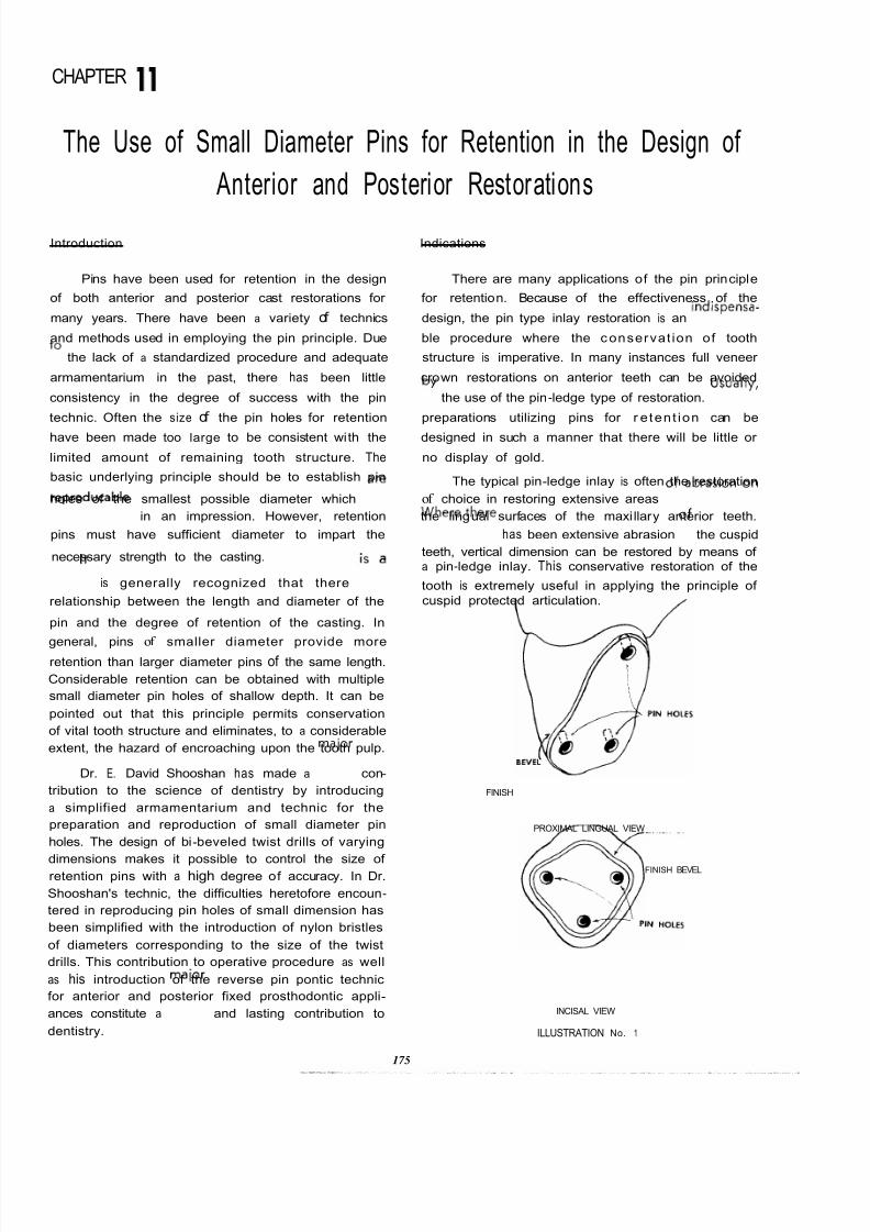
8/11/2019 An Atlas of Cast Gold Procedures
http://slidepdf.com/reader/full/an-atlas-of-cast-gold-procedures 184/270
CHAPTER
The Use of Small Diameter Pins for Retention in the Design of
Anterior and Posterior Restorations
Introduction Indications
Pins have been used for retention in the design There are many applications of the pin principle
of both anterior and posterior cast restorations for for retention. Because of the effectiveness of the
many years. There have been a variety of technics design, the pin type inlay restoration is an indispensa-
and methods used in employing the pin principle. Due ble procedure where the c onservat ion of tooth
to the lack of a standardized procedure and adequate structure is imperative. In many instances full veneer
armamentarium in the past, there has been little crown restorations on anterior teeth can be avoided
consistency in the degree of success with the pin by the use of the pin-ledge type of restoration. Usually
technic. Often the size of the pin holes for retention preparations utilizing pins for r e tent ion can be
have been made too large to be consistent with the designed in such a manner that there will be little or
limited amount of remaining tooth structure. The no display of gold.
The typical pin-ledge inlay is often the restorationbasic underlying principle should be to establish pin
holes of the smallest possible diameter which are of choice in restoring extensive areas of abrasion on
reproducable in an impression. However, retention the lingual surfaces of the maxi llary anterior teeth.
pins must have sufficient diameter to impart the Where there
has been extensive abrasion o the cuspid
necessary strength to the casting. teeth, vertical dimension can be restored by means ofa pin-ledge inlay. This conservative restoration of the
tooth is extremely useful in applying the principle of
cuspid protected articulation.
It is generally recognized that there is a
relationship between the length and diameter of the
pin and the degree of retention of the casting. In
general, pinsof
smaller diameter provide moreretention than larger diameter pins of the same length.
Considerable retention can be obtained with multiple
small diameter pin holes of shallow depth. It can be
pointed out that this principle permits conservation
of vital tooth structure and eliminates, to a considerable
extent, the hazard of encroaching upon the tooth pulp.
Dr. E. David Shooshan has made a maior
con-
tribution to the science of dentistry by introducing
a simplified armamentarium and technic for the
preparation and reproduction of small diameter pin
holes. The design of bi-beveled twist drills of varying
dimensions makes it possible to control the size ofretention pins with a high degree of accuracy. In Dr.
Shooshan's technic, the difficulties heretofore encoun-
tered in reproducing pin holes of small dimension has
been simplified with the introduction of nylon bristles
of diameters corresponding to the size of the twist
drills. This contribution to operative procedure as well
as his introduction of the reverse pin pontic technic
for anterior and posterior fixed prosthodontic appli-
ances constitute a maior and lasting contribution to
dentistry.
175
FINISH
PROXIMAL LINGUAL VIEW
FINISH BEVEL
INCISAL VIEW
ILLUSTRATION No. 1

8/11/2019 An Atlas of Cast Gold Procedures
http://slidepdf.com/reader/full/an-atlas-of-cast-gold-procedures 185/270
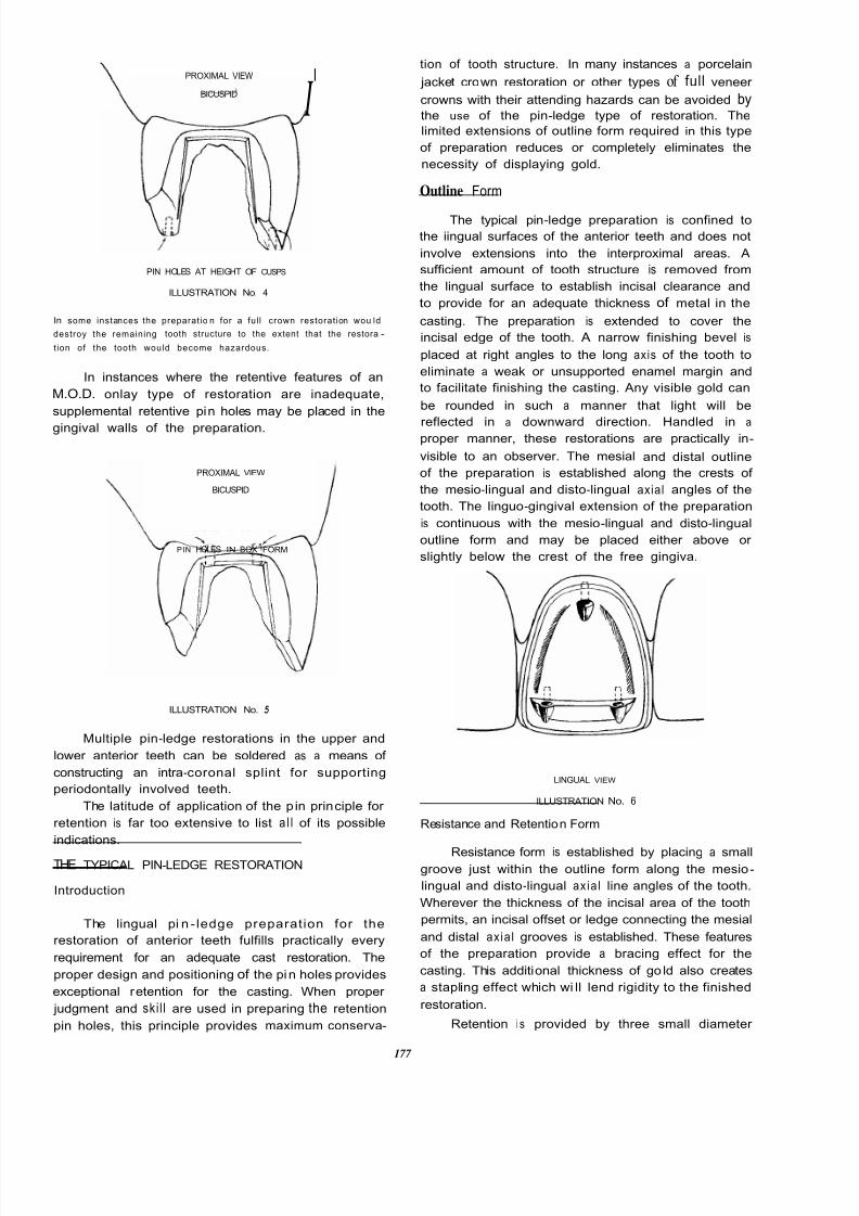
8/11/2019 An Atlas of Cast Gold Procedures
http://slidepdf.com/reader/full/an-atlas-of-cast-gold-procedures 186/270
IPROXIMAL VIEW
\
BICUSPID
I
PIN HOLES AT HEIGHT OF CUSPS
ILLUSTRATION No. 4
In some instances the preparat io n for a ful l crown restorat ion wou ld
destroy the remaining tooth structure to the extent that the restora-
t ion of the tooth would become hazardous.
In instances where the retentive features of an
M.O.D. onlay type of restoration are inadequate,
supplemental retentive pin holes may be placed in the
gingival walls of the preparation.
PROXIMAL VIEW
BICUSPID
PIN HOLES IN BOX FORM
ILLUSTRATION No. 5
Multiple pin-ledge restorations in the upper and
lower anterior teeth can be soldered as a means of
constructing an intra-coronal splint for supporting
periodontally involved teeth.
The latitude of application of the p in principle for
retention is far too extensive to list a l l of its possible
indications.
THE TYPICAL PIN-LEDGE RESTORATION
Introduction
The lingual pi n - ledge preparat ion for the
restoration of anterior teeth fulfills practically every
requirement for an adequate cast restoration. The
proper design and positioning of the pin holes provides
exceptional retention for the casting. When proper
judgment and skill are used in preparing the retention
pin holes, this principle provides maximum conserva-
tion of tooth structure. In many instances a porcelain
jacket crown restoration or other types of full veneer
crowns with their attending hazards can be avoided bythe use of the pin-ledge type of restoration. The
limited extensions of outline form required in this type
of preparation reduces or completely eliminates the
necessity of displaying gold.
Outline Form
The typical pin-ledge preparation is confined to
the iingual surfaces of the anterior teeth and does not
involve extensions into the interproximal areas. A
sufficient amount of tooth structure is removed from
the lingual surface to establish incisal clearance and
to provide for an adequate thickness of metal in the
casting. The preparation is extended to cover the
incisal edge of the tooth. A narrow finishing bevel is
placed at right angles to the long axis of the tooth to
eliminate a weak or unsupported enamel margin and
to facilitate finishing the casting. Any visible gold can
be rounded in such a manner that light will be
reflected in a downward direction. Handled in aproper manner, these restorations are practically in-
visible to an observer. The mesial and distal outline
of the preparation is established along the crests of
the mesio-lingual and disto-lingual axial angles of the
tooth. The Iinguo-gingival extension of the preparation
is continuous with the mesio-lingual and disto-lingual
outline form and may be placed either above or
slightly below the crest of the free gingiva.
LINGUAL VIEW
ILLUSTRATION No. 6
Resistance and Retention Form
Resistance form is established by placing a smallgroove just within the outline form along the mesio-
lingual and disto-lingual axia l line angles of the tooth.
Wherever the thickness of the incisal area of the tooth
permits, an incisal offset or ledge connecting the mesial
and distal axia l grooves is established. These features
of the preparation provide a bracing effect for the
casting. This additional thickness of go ld also creates
a stapling effect which wi ll lend rigidity to the finished
restoration.
Retention i s provided by three small diameter
177

8/11/2019 An Atlas of Cast Gold Procedures
http://slidepdf.com/reader/full/an-atlas-of-cast-gold-procedures 187/270
pins. Two retention pins are placed in thelinguo-
incisal area and one pin in the cingulum area. The
incisal pins are p la ce d in d e n t i n just inside the
dentino-enamel junction in the regions of the mesial
and distal angles of the tooth. Care must be taken that
adequate dentin coverage be maintained under the
labial enamel surface to prevent the casting from
showing any possible shadow from the labial aspect.
It is necessary to employ a small diameter drill when
preparing pin holes for retention in anterior teeth with
thin incisal edges. The slope of the lingual surfaces of
the anterior teeth must also be considered in deter -
mining both the size of the pin hole and its exact
position. There must be sufficient bulk of tooth
structure lingual to the pin to provide the necessary
strength for support of the casting. A slight lingual
offset or ledge established with a small diameter
diamond tapered stone with a flat end is very bene-
f icial in providing a guide for positioning and starting
these retentive features. This approach eliminates
leaving a thin fragile edge of tooth structure at the
crest of the p in hole which would be subject to fracture.
A third pin is placed in the cingulum area of the
tooth. The histological. relationship of the structures of
the anterior teeth permits the placement of a pin hole
of greater depth ir the cingulum portion of the tooth
than in the incisal region. This naturally depends upon
the direction in which the pin hole is prepared. The
direction and depth of the retention pin holes are
dependent upon three factors: (a) the type of tooth
form (ovoid, tapering or square); (b) a thorough knowl-
edge of histology, and (c) a critical examination of the
radiographs of the teeth.
After making a proper survey clinically and
radiographically, the position, direction and depth of
the linguo-incisal retention pin holes should be deter -
mined. While no single rule can be applied in
establishing the direction of these pin holes for al l
tooth forms, it can be stated that they may generally
be established with a slight lingual inclination in
relationship to the long axis of the tooth. This provides
a slight lingual direction of withdrawal for the pattern
or casting. After the most favorable position, direction,and depth, have been established for the linguo-incisal
pin holes, the position of the third retention pin hole
in the cingulum area is determined. A labio-lingual
section of an extracted tooth will demonstrate the
favorable bulk of dentin over lying the pulp in this
area. This makes it possible to establish the lingual pin
hole in the cingulum area in such a relationship to
the lingual surface of the tooth and pulp chamber that
there is adequate bulk of dentin surrounding the pin
hole in both the lingual and pulpal direction.
ILLUSTRATION No. 7
Al l surrounding cavo-surface margins of th
preparation should be definite and continuous.
A Modi f ied Part ial Veneer Anterior Restoration
A modification o f the typical pin-ledge restoratio
is one in which an interproximal area i s involve
Retention for this restoration is provided essential
by a groove in the involved interproximal area su
plemented by pins in the cingulum area and in th
region of the remaining intact incisal angle of th
tooth. The design of the interproximal portion of th
preparation has been described in detail in Chapte
10 on the three-quarter crown restoration. As in th
instance of the pin-ledge preparation, the design
the incisal lingual and gingival outline form wit
features of resistance and retention form are esta
lished after a thorough radiographic and clinic
examination has been made. These features a
described in detail under the preceding heading "Th
Typical Pin-Ledge Restoration." This preparation als
utilizes retention from the collar -like form of th
preparation around the cingulum of the tooth simila
to that of the threequarter crown.
LINGUAL FINISH LINE
CREST OF GINGIVA. I,
A
PROXIMAL
GROOVE.
NCISAL OFFSn
LINGUAL VIEW
178
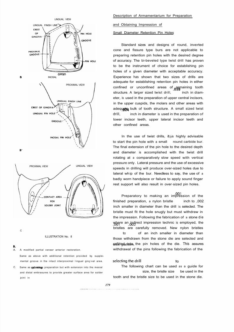
8/11/2019 An Atlas of Cast Gold Procedures
http://slidepdf.com/reader/full/an-atlas-of-cast-gold-procedures 188/270
Description of Armamentarium for Preparation
and Obtaining Impression of
Small Diameter Retention Pin Holes
LINGUAL VIEW
LINGUAL FINISH LINE
Standard sizes and designs of round, inverted
cone and fissure type burs are not applicable to
preparing retention pin holes with the desired degree
of accuracy. The bi-beveled type twist drill has proven
to be the instrument of choice for establishing pin
holes of a given diameter with acceptable accuracy.
INCISALOFFSET- Experience has shown that two sizes of drills are
B
\ PROXIMAL VIEW I
PROXIMAL VIEW LINGUAL VIEW
A.
B.
C.
adequate for establishing retention pin holes in either
confined or unconfined areas of remaining tooth
structure. A larger sized twist dr il l, .028 inch in diam-
eter, is used in the preparation of upper central incisors,
in the upper cuspids, the molars and other areas with
adequate bulk of tooth structure. A small sized twist
drill, .024 inch in diameter is used in the preparation of
lower incisor teeth, upper lateral incisor teeth and
other confined areas.
In the use of twist drills, it is highly advisable
to start the pin hole with a small Z round carbide bur.
The final extension of the pin hole to the desired depth
and diameter is accomplished with the twist drill
rotating at a comparatively slow speed with vertical
pressure only. Lateral pressure and the use of excessive
speeds in drilling will produce over -sized holes due to
lateral wh ip of the bur. Needless to say, the use of abadly worn handpiece or failure to apply sound finger
rest support will also result in over -sized pin holes.
Preparatory to making an impression of the
finished preparation, a nylon bristle .001 inch to ,002
inch smaller in diameter than the drill i s selected. The
bristle must fit the hole snugly but must withdraw in
the impression. Following the fabrication of a stone die
where an indirect impression technic is employed, the
bristles are carefully removed. New nylon bristlesC
ILLUSTRATION No. 8
A modif ied part ia l veneer anterior restorat ion.
001 to002
of an inch smaller in diameter than
those withdrawn from the stone die are selected and
refitted into the pin holes of the die. This assures
withdrawal of the pins following the fabrication of the
Same as above with addit ional retent ion provided by supple-
mental groove in the intact interproximal l ingual ging ival area.
wax
pattern.
Same as pin-ledge preparat ion but with extension into the mesial
and distal embrasures to provide greater surface area for solder
jo in t i n s p : i n t i n g .
The following chart can be used as a guide for
selecting the drill size, the bristle size to be used in the
tooth and the bristle size to be used in the stone die.
179

8/11/2019 An Atlas of Cast Gold Procedures
http://slidepdf.com/reader/full/an-atlas-of-cast-gold-procedures 189/270
Chart for Drill and Corresponding Bristle Sizes;
large Teeth (upper anteriors, some bicuspids and
moIars)
Drill size _ ________________ _ _
028
Bristle in tooth __ . _ _ _ . . _ _ _ _ ______027
Bristle for pattern______._. . ._
026
Small Teeth (lower anteriors, small upper anteriors
and other confined areas)
Drill size . . . . ._. . . ._. . .____________
024
Bristle in tooth. . . . . .____________
022
Bristle for pattern ..... ...... .020
At times some dif ficulty is encountered in
obtaining the proper fit of the bristles in the pin holes
both in the tooth and in the stone die. This is due
to inaccuracy in preparing the pin holes and incon-
sistency in the size tolerances of the twist drills and
nylon bristles. This problem i s easily overcome by
having available a variety of bristle sizes ranging from
.020 inch to and including .028 inch in diameter. The
sizes are increased by increments of one thousandth
of an inch. The availability of these assorted sizedbristles make it possible to select a bristle which will
fit the pin holes in the prepared tooth and the stone
die in a l l instances. They should fit rather snugly but
must withdraw easily with the impression or wax
pattern.
The following illustrations demonstrate the use
of small diameter pins to aid in restoring the axial
length of those teeth destroyed by advanced caries or
abrasion.
ILLUSTRATION No. 9
The following technique i s particularly applicable to teeth which
must be restored to serve as a fixed bridge abutment where
parallelism is a factor. It is also useful in cases where tissue
management requires a gingivectomy or osseous surgical intervention.
A
B
180
F
A. Buccal view of fractured or carious mandibular molar.
B. Histological section of fractured or carious mandibula r molar wit
vital pulp. The remaining tooth structure i s inadequate to suppo
and retain a full veneer cast crown.
C. A minimum of four small diameter pin holes may be placed in
sound dentin without encroaching upon the pulp.
D. It i s imperative that the operator have a thorough knowledge o
dental histology as well as Bite-Wing radiographs before pre
paring these retentive pin holes. The pin holes are placed i n soun
dentin and are prepared 2 to 3 mm. in depth.
E. The remaining tooth structure and pin holes are reproduced in
hydrocal stone by using nylon plastic bristles with hydrocolloid o
rubber base impression .material. A casting is made to restore
lost tooth structure. This will establish the necessary length for a
full veneer crown preparation.
F. After the costing has been cemented to place, the preparation i
completed by establishing the chamfered finish line under the
protection of the free gingiva.

8/11/2019 An Atlas of Cast Gold Procedures
http://slidepdf.com/reader/full/an-atlas-of-cast-gold-procedures 190/270
FURTHER APPLICATION OF FUNDAMENTAL PRINCIPLES OF CAVITY DESIGN
FOR THE RESTORATION OF GROSSLY DESTROYED TEETH
Intra-coronal preparations with o wide occlusal isthmus and o deep
pulpal floor will often weoken the buccal and or lingual cusps,
subjecting them to fracture.
Modification of the three-quarter crown preparation with o lingual
pin, ploced judiciously to ovoid the pulp, wi ll permit this tooth
to be restored to normol function.
The addition of a Class Five restoronun will further weoken the
buccal cusp and predispose to its fracture.
A fu ll veneer preparation wi th offset at gingi val wi ll permit fobri.
coting a full coveroge crown with esthetic facing.
8
Weakened
or box forms.
and
and
fracture. Add itional retention may be gained by use of pins
in cusps
from
box form includes
the fractured cusp. The remaining cusps ore copped, protecting them
distal
unsupported cusps of the molar teeth are subject to
excessive stresses which tend to cause their fracture.
An M.O.D. onlay preparation with modified

8/11/2019 An Atlas of Cast Gold Procedures
http://slidepdf.com/reader/full/an-atlas-of-cast-gold-procedures 191/270
’
,--. e-\
I
\
When large intra-coronal and buccal or lingual Class V restorations
have been placed in the some tooth, the buccal or ling ual cusps are
weakened, often resulting in their fracture.
A modified reverse three-quarter crown preparation has been de-
signed to return this molar to function. Added retention has been
provided by using two pins in the lingual cusps and three grooves in
the bucco-axial wall.
The occlusal, both proximals and buccal pi t are grossly invaded b y
caries. The remaining weakened tooth structure is not sufficient to
provide typical box forms and line angles for adequate retention.
Al l decay has been removed and the cusps adequately capped for
protection. Retention i s then provided by a series of pins placed in
the remaining cusps and proximal areas. Please note that these pins
are placed in dentin and do not encroach upon the pulp tissue.
Root caries (presenile] well beyond present proximo1 restoration. The outli ne form i s extended to include the root caries without
establishing a gingival floor. This will avoid encroachment on the
pulp. Additional retention i s established by accentuating the proxima
line angles. The las t vestige of decay i s removed prior to cementation
of the restoration.
181 1

8/11/2019 An Atlas of Cast Gold Procedures
http://slidepdf.com/reader/full/an-atlas-of-cast-gold-procedures 192/270
ARMAMENTARIUM FOR THREE-QUARTER CROWN AND
OTHER PARTIAL VENEER CROWN RESTORATIONS
PREPARATION
TAPERED WEDGE
6 9 9 TAPERING FISSURE BUR
700 TAPERING FISSURE BUR
’z ROUND CARBIDE BUR
9 MM. SAFE SIDE DIAMOND DISC
LIGHTNING STRIP
LIGHTNING DISC
MEDIUM SIZE ROUND END TAPERED DIAMOND STONE
MEDIUM SIZE FLAME SHAPE DIAMOND STONE
SMALL DOUGHNUT SHAPE DIAMOND STONE
MEDIUM SIZE CORK SHAPE DIAMOND STONE
WHITE POLY STONE
MEDIUM SIZE TAPERED SQUARE END DIAMOND STONE
. 0 2 8 INCH BI-BEVEL TWIST DRILL
. 0 2 4 INCH BI-BEVEL TWIST DRILL
IMPRESSION
HYDROCOLLOID IMPRESSION MATERIAL AND ACCESSORIES
[ref. Chapter 4 )
RUBBER BASE IMPRESSION MATERIAL AND ACCESSORIES
ALGINATE IMPRESSION MATERIAL (TEMPORIZING)
NYLON BRISTLES, , 0 2 8 INCH, , 0 2 7 INCH, . 0 2 6 INCH, . 0 2 4 INCH,
, 0 2 2 INCH, . 0 2 0 INCH
SINGLE EDGE RAZOR BLADE
SPECIAL BRISTLE PLIERS (Engelhardt)
COLD CURE PLASTIC (TEMPORIZING)
ZINC-OXIDE EUGENOL CEMENT
STONE MODELS AND WAXING (refer chaDter 5
INVESTING AND CASTING (refer chanter 61
FINISHING AND CEMENTATION (refer chapter 7
SPECIAL INSTRUMENTS FOR FINISHING
SPRAY BOTTLE WITH FINE FLOUR OF PUMICE
2 ROUND BUR
LENTULO 4 PASTE FILLER

8/11/2019 An Atlas of Cast Gold Procedures
http://slidepdf.com/reader/full/an-atlas-of-cast-gold-procedures 193/270

8/11/2019 An Atlas of Cast Gold Procedures
http://slidepdf.com/reader/full/an-atlas-of-cast-gold-procedures 194/270
With a small flame-shaped diamond, extend finish line of
flare . . .
. . . toward cingulum area.
With a bullet-shaped diamond prepare cingulum wall parallel to line of shed.
With a small doughnut-shaped diamond . . . reduce lingual surface for clearance.
183

8/11/2019 An Atlas of Cast Gold Procedures
http://slidepdf.com/reader/full/an-atlas-of-cast-gold-procedures 195/270
With a cork-shaped diamond
With a cork-shaped diamond
. . . make a V-shaped groove in the marginal ridge are
terminating the groove at the crest of the marginal ridg
. . . establish the necessary incisal clearance.
Use the cork-shaped diamond . , to connect the marginal ridge and incisal cuts.

8/11/2019 An Atlas of Cast Gold Procedures
http://slidepdf.com/reader/full/an-atlas-of-cast-gold-procedures 196/270
With a sharpened lead pencil make a mark on the edge of
the incisal and proximal margins.
Use a small flame-shaped diamond
. . . to make a starting notch for the proximal groove Place a tarJered fissure bur in the notch
. . . and establish a groove equal in width to the diameter
of the bur.
The groove should be prepared to a maximum length with-
out extending it beyond the finish line or flare.
185
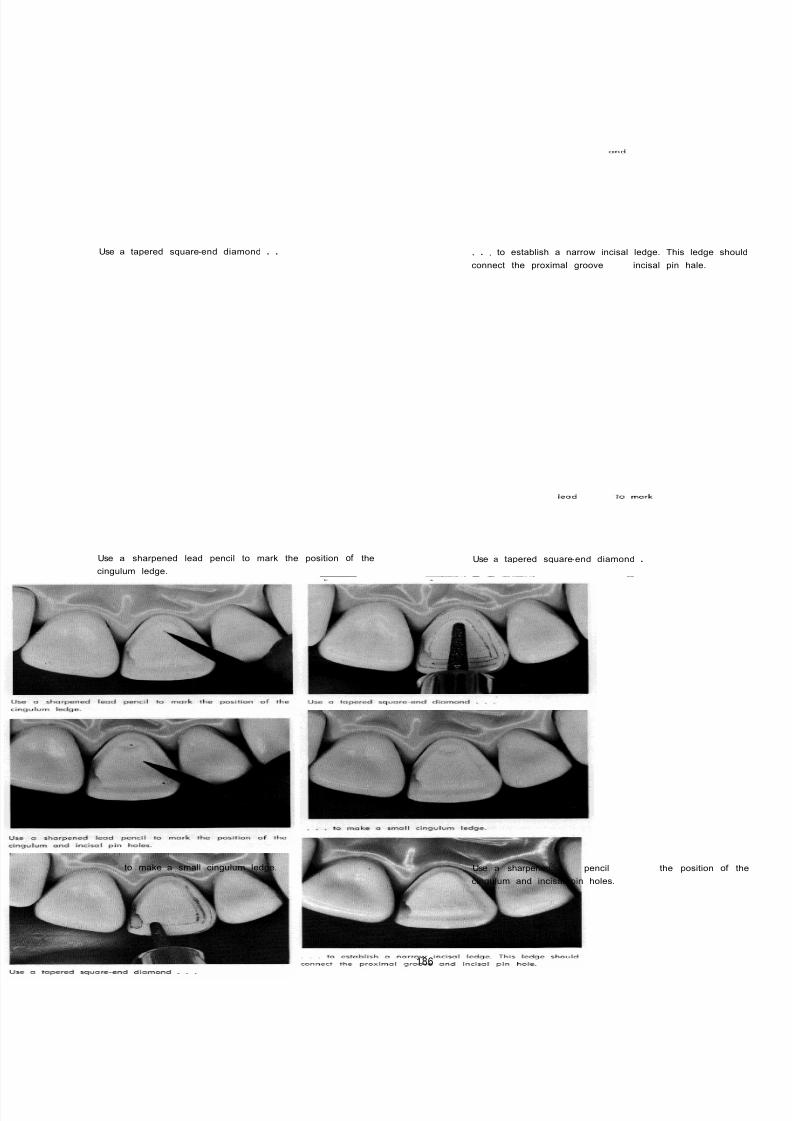
8/11/2019 An Atlas of Cast Gold Procedures
http://slidepdf.com/reader/full/an-atlas-of-cast-gold-procedures 197/270
Use a tapered square-end diamond . . . . , to establish a narrow incisal ledge. This ledge shou
connect the proximal groove and incisal pin hale.
Use a sharpened lead pencil to mark the position of the
cingulum ledge.
Use a tapered square-end diamond .
to make a small cingulum ledge. Use a sharpened lead pencil to mark the position of t
cingulum and incisal pin holes.
186
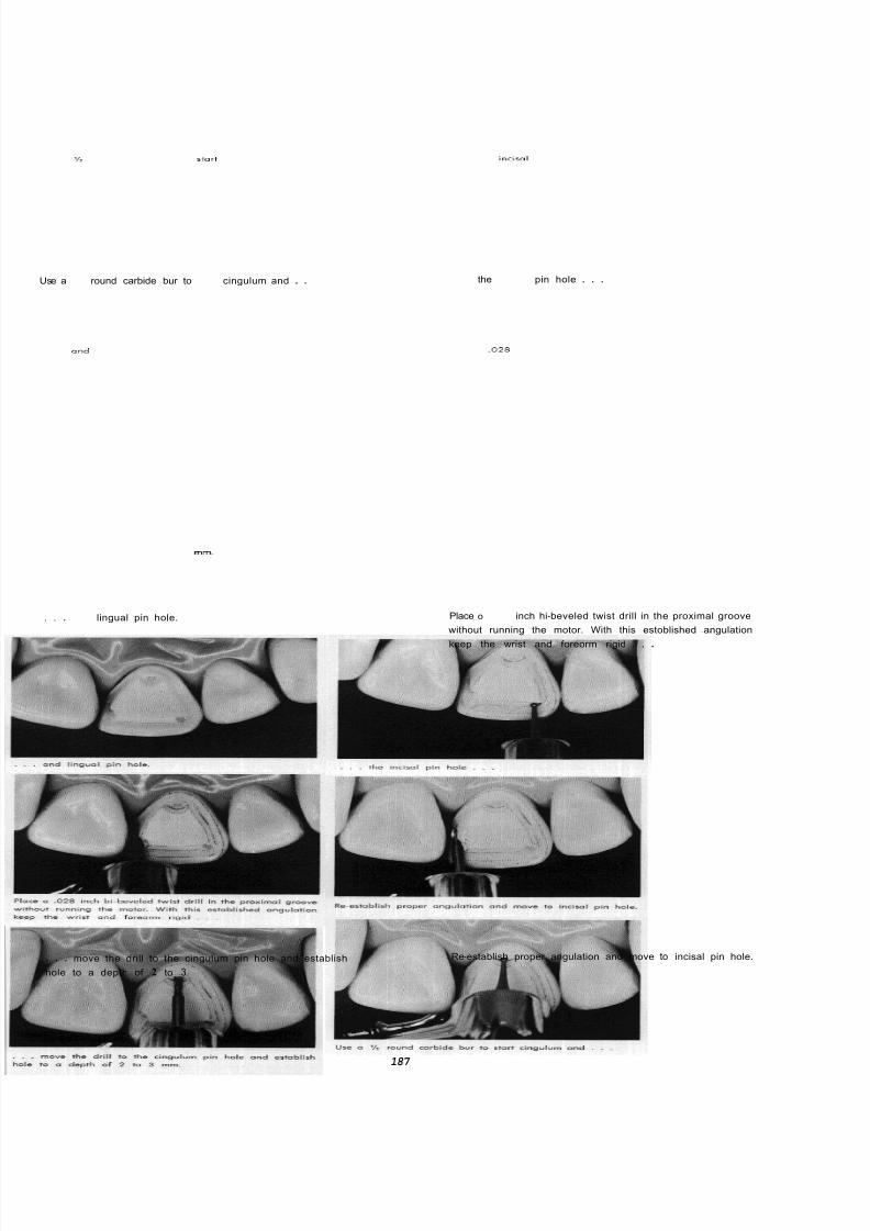
8/11/2019 An Atlas of Cast Gold Procedures
http://slidepdf.com/reader/full/an-atlas-of-cast-gold-procedures 198/270
Use a round carbide bur to start cingulum and . . the incisol pin hole . . .
. . . and lingual pin hole. Place o 0 2 8 inch hi-beveled twist drill in the proximal groove
without running the motor. With this estoblished angulation
keep the wrist and foreorm rigid . . .
. . . move the drill to the cingulum pin hole and establish
hole to a depth of 2 to 3 mm.
Re-establish proper angulation and move to incisal pin hole.
187

8/11/2019 An Atlas of Cast Gold Procedures
http://slidepdf.com/reader/full/an-atlas-of-cast-gold-procedures 199/270
Drill hole 2 to 3 mm. deep. Pin holes drilled porallel to proximal groove.
With a reshaped white polystone, make a finishing bevel
on the incisal margin /4 to 1/2 mm. wide and at right angles
to the long oxis of the preparation.
Scrape the marginal ridge cavo-surface margin with o
angle chisel or hoe.
Detail of finished preparation; p in holes parallel to proximal
groove, cingulum wall parollel to pin holes and groove,
incisal pin hole occupying position that a groove might oc-
cupy, marginal ridge cavo-surface margin terminated at
crest of marginal ridge.
188

8/11/2019 An Atlas of Cast Gold Procedures
http://slidepdf.com/reader/full/an-atlas-of-cast-gold-procedures 200/270
PROCEDURES FOR IMPRESSION AND C O M P L E T I O N OF PLASTIC TEMPORARY
028 inch and .024 inch bi-beveled twist drills. 018 inch to
028 inch nylon plastic bristles in kit form.
, , . and immediately press against cold metallic surface
to form a nail head.
Plastic bristles and special pliers for handling
nail head.
bristles with
Soften the end of bristle on side of bunsen flame
Place bristle on I paper towel and cut to desired length with
a sharp single-edge razor blade.
Select a bristle whose diameter will fit the pin hole " just
right"; that will be snug but can easily be removed with
the impression.
189
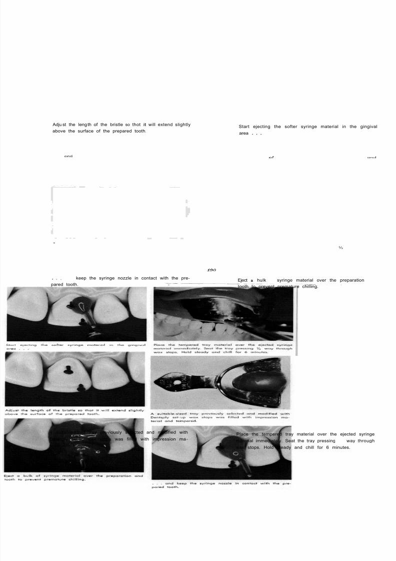
8/11/2019 An Atlas of Cast Gold Procedures
http://slidepdf.com/reader/full/an-atlas-of-cast-gold-procedures 201/270
Adjust the length of the bristle so thot it will extend slightly
above the surface of the prepared tooth.
. . , and keep the syringe nozzle in contact with the pre -
pared tooth.
A - suitable-sized tray previously selected and modified with
Dentsply set-up wax stops was filled with impression ma -
terial and tempered.
Start ejecting the softer syringe material in the ging
area . . .
Eject a hulkof
syringe material over the preparation a
tooth to prevent premature chilling.
Place the tempered tray material over the ejected syring
material immediately. Seat the tray pressing 12 way throug
wax stops. Hold steady and chill for 6 minutes.
190

8/11/2019 An Atlas of Cast Gold Procedures
http://slidepdf.com/reader/full/an-atlas-of-cast-gold-procedures 202/270
Finished impression. It i s advisable to make three good im -
pressions, two for the master dies and one for articulated
model.
Cut away the interproximal extensions of the alginate im-
pression so that it can be reseoted in the mouth.
Fit nylon plastic pins in pin holes of preparation and flat -
ten heads of bristles close to surface of preparation.
Mix cold cure plastic and
fill recess of prepared tooth and seat tray in mouth
191
Remove tray while plastic i s still in a rubbery state.

8/11/2019 An Atlas of Cast Gold Procedures
http://slidepdf.com/reader/full/an-atlas-of-cast-gold-procedures 203/270

8/11/2019 An Atlas of Cast Gold Procedures
http://slidepdf.com/reader/full/an-atlas-of-cast-gold-procedures 204/270
PROCEDURES FOR PREPARATION OF MODELS, WAXING, FINISHING CASTING AND CEMENTATION.
While the troy of hydrocolloid is being chilled, contour and
polish the temporary plastic restoration. Place a mix of zinc
oxide eugenol cement on the internal surface of the tem-
porary plastic restoration. Keep the cement away from the
pins.
Separate -one of the master die impressions
Cement the temporary plastic restoration and remove all
excess cement beyond the margins.
. . . and make a master die, 3 4 inch over -all, tapered from
the extent of the impression and remove all interfering bulk
of stone.
With cotton plierscarefully remove the plastic pins
193

8/11/2019 An Atlas of Cast Gold Procedures
http://slidepdf.com/reader/full/an-atlas-of-cast-gold-procedures 205/270
Fit a slightly smaller diameter plastic pin in the master
stone die.
. . . flatten these pins close to surface of the die.
. . . flow the molten wax on the stone die.
With a hot wax spatula . . .
Liquefy the inlay wax in a metal dish and with waxin
pliers . . .
Build up the wox pattern to general contour, ready to plac
on the working model.
194

8/11/2019 An Atlas of Cast Gold Procedures
http://slidepdf.com/reader/full/an-atlas-of-cast-gold-procedures 206/270
With a 700 tapered fissure or 1 round bur, enlarge the
pin holes on the working model.
Finish the wax pattern on the master die and place a drop
of Kerr's wax-up wax in the center of the patternn just gin-
gival to the incisal edge of the pattern.
--
Cleaned and dried casting.
This will permit placing the wax pattern on the working
model without danger of separating the pins from the wax
pattern.
X
Attach an 18-gauge hallow sprue to the drop of wax,
parallel to the line of shed.
Place casting in hot cyanide stripping solution and strip for
5 seconds.
195
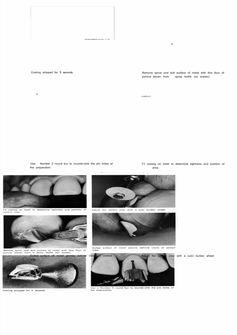
8/11/2019 An Atlas of Cast Gold Procedures
http://slidepdf.com/reader/full/an-atlas-of-cast-gold-procedures 207/270
- _r-- - x_
Costing stripped for 5 seconds. Remove sprue ond dull surface of metal with fine flour
pumice blown from spray bottle (oir eraser).
Use Number 2 round bur to counter -sink the pin holes of
the preparation.
Fi t costing on tooth to determine tightness and position
contoct area.
Dulled surface of metal permits definite vision of contoct
area.
Adjus t the contact orea with a sulci burlew wheel.
196
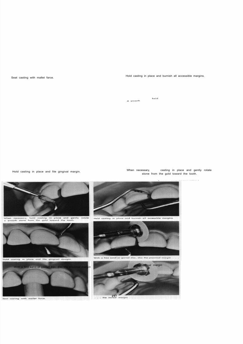
8/11/2019 An Atlas of Cast Gold Procedures
http://slidepdf.com/reader/full/an-atlas-of-cast-gold-procedures 208/270
Seat casting with mallet farce.
Hold casting in place and file gingival margin.
With a fine sand or garnet disc, disc the proximal margin
197
Hold casting in place and burnish all accessible margins.
When necessary, hold casting in place and gently rotate
a smooth
stone from the gold toward the tooth.
the incisal margin

8/11/2019 An Atlas of Cast Gold Procedures
http://slidepdf.com/reader/full/an-atlas-of-cast-gold-procedures 209/270
. . . and the lingual proximal margin, rotating the disc
from the gold toward the tooth,
Place cement over the preparation . , ,
Seat the casting with finger pressure followed by mallet farce.
Use a Lentulo Number 4 paste filler in the contra an
handpiece, rotating the instrument slowly, to carry the
ment to the bottom of the Din holes.
. . . and inside the costing
Hold casting firmly in place and use a fine cuttle disc ove
all accessible margins while the cement i s sti l l soft.
198

8/11/2019 An Atlas of Cast Gold Procedures
http://slidepdf.com/reader/full/an-atlas-of-cast-gold-procedures 210/270
Remove all excess' hardened cement and start final finish
with fine wet pumice in a rubber cup.
Lingual view of finished restoration
Use one of the high luster moterials to complete final polish.
Care should be exercised during the entire finishing process
to ovoid overheating the tooth.
This restoration may be made to fulfill all requirements of
resistance and retention form as well as esthetics.
199

8/11/2019 An Atlas of Cast Gold Procedures
http://slidepdf.com/reader/full/an-atlas-of-cast-gold-procedures 211/270

8/11/2019 An Atlas of Cast Gold Procedures
http://slidepdf.com/reader/full/an-atlas-of-cast-gold-procedures 212/270
TOP PLATE
Injecting hydrocolloid around nylon plastic bristles.
BOTTOM PLATE
Using fine pumice in spray bottle as an air eraser.

8/11/2019 An Atlas of Cast Gold Procedures
http://slidepdf.com/reader/full/an-atlas-of-cast-gold-procedures 213/270
CHAPTER 2
Occlusal I and Class V Inlay Preparations, Procedures for
Wax Pattern, Finishing and Cementation
OCCLUSAL INLAY RESTORATIONS
Indications
The indication for cast g old as a restorative
medium in the occlusal surfaces of posterior teeth
depends largely upon the extent of caries and the
amount of tooth structure to be restored. The use of
gold foil is indicated in occlusal restorations where the
fundamental principles of cavity design may be accom-
plished with a minimum of extension of outline form.
The indication for gold asa
restorative medium in theocclusal surfaces of posterior teeth also depends upon
the degree of caries immunity in the individual mouth
and the type of oral hygiene practiced by the patient.
For example, it would be poor judgment to place these
restorations routinely in the very young adult since
future immunity to interproximal caries cannot be
entirely foreseen.
FUNDAMENTAL PRINCIPLES OF CAVITY DESIGN
Outline Form
The outline form for cavities occurring in theocclusal surfaces of bicuspid and molar teeth varies
with the anatomy and form of the individual tooth. The
outline form should be extended to include any f is-
sured pits and grooves on the occlusal surfaces since
these areas are highly susceptible to recurrence of
caries. The outline form must be extended to a position
where the grooves become shallow and rounded or
approach an anatomical ridge. This places the margins
of the restoration in self -cleansing areas and in areas
where they can be properly finished and polished.
The mesial and distal bucco-lingual walls of the
preparation should be established parallel to the
marginal ridges and should be extended to include any
fissured buccal and lingual supplemental grooves.
These walls should be established approximately one-
half the distance between the depth of the mesial or
distal pit and the crest of the marginal ridge. This guide
provides extension into finishing and self -cleansing
areas but prevents excessive extension which would
result in weakening a marginal ridge of tlle tooth. This
guide also applies in determining the extension of the
preparation wall which approximates an oblique ridge
of an upper molar tooth or a transverse ridge of a
lower bicuspid tooth.
The buccal and lingual ou t l ine f o rm of the
preparation follows the curvature of the mesial and
distal slopes of the buccal and lingual cusps of the tooth.
A
C
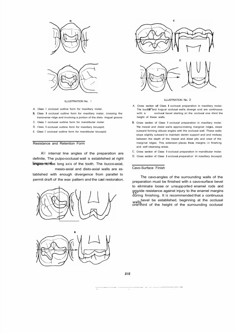
8/11/2019 An Atlas of Cast Gold Procedures
http://slidepdf.com/reader/full/an-atlas-of-cast-gold-procedures 214/270
D
_c
E
ILLUSTRATION No. 1
A. Class I occlusal outline form for maxillary molar.
B. Class I occlusal outline form for maxillary malar, crossing the
transverse ridge and involving a portion of the disto-lingual groove.
C. Class I occlusal outline form for mandibular molar.
D. Class I occlusal outline form for maxillary bicuspid.
E. Class I occlusal outline form for mandibular bicuspid.
Resistance and Retention Form
Al l internal line angles of the preparation are
definite, The pulpo-occlusal wall is established at right
angles to the long axis of the tooth. The bucco-axial,
linguo-axial, mesio-axial and disto-axial walls are es-
tablished with enough divergence from parallel topermit draft of the wax pattern and the cast restoration.
A
A.
B.
C.
D.
D
ILLUSTRATION No. '2
Cross section of Class I occlusal preparation in maxillary mol
The buccal and lingual occlusal wal ls diverge and are continuo
with a 15 occlusal bevel starting a t the occlusal one-third t
height of these walls.
Cross section of Class I occlusal preparation in maxillary mola
The mesial and distal wal ls approx imating marginal ridges, slo
outward forming obtuse angles with the occlusal wall. These wa
slope slightly outward to maintain dentin support and end midw
between the depth of the mesial and distal pits and crest of th
marginal ridges. This extension places these margins i n finishi
and self -cleansing areas.
Cross section of Class I occlusal preparation in mandibular mola
Cross section of Class I occlusal preparati on in maxillary bicusp
Cavo-Surface Finish
The cavo-angles of the surrounding walls of th
preparation must be finished with a cavo-surface bev
to eliminate loose or unsupported enamel rods an
provide resistance against injury to the enamel margi
during finishing. It i s recommended that a continuo
15' bevel be established, beginning at the occlus
one-third of the height of the surrounding occlus
walls.
202
8/11/2019 An Atlas of Cast Gold Procedures
http://slidepdf.com/reader/full/an-atlas-of-cast-gold-procedures 215/270
ARMAMENTARIUM FOR OCCLUSAL PREPARATION, DIRECT WAX PATTERN,
FINISHING AND CEMENTATION
PREPARATION4
700 - 701 TAPER FISSURE BUR
WHITE POLY STONE
DIRECT WAX PATTERN
HARD INLAY WAX
EGG BURNISHER
TANNER CARVER
ACETONE
3 EXPLORER
# 7 WAX SPATULA
SPRAY BOTTLE WITH 3% HYDROGEN PEROXIDE
18 GAUGE HOLLOW SPRUE
INVESTING AND CASTING (ref.
ChaDter
6)
FINISHING AND CEMENTATION
701 TAPER FISSURE BUR
SULCI BURLEW WHEEL
HOLDING INSTRUMENT
ASSORTED PLUG FINISHING BURS
SPECIAL POINTED INSTRUMENT (made from old straight instrument.)
FINE CUTTLE DISCS
END BRUSH AND RUBBER CUP WITH FINE PUMICE
TIN OXIDE OR CHAULK
203
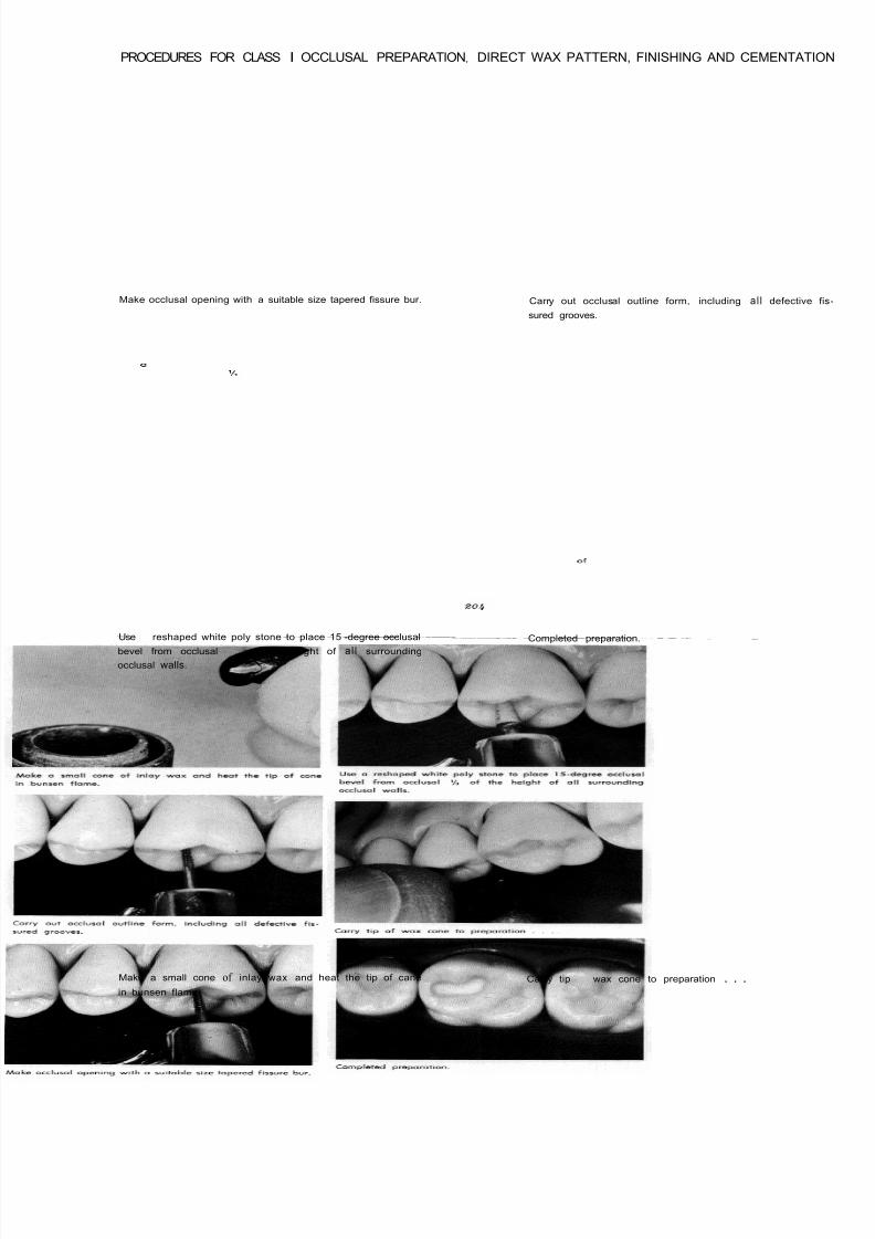
8/11/2019 An Atlas of Cast Gold Procedures
http://slidepdf.com/reader/full/an-atlas-of-cast-gold-procedures 216/270
PROCEDURES FOR CLASS I OCCLUSAL PREPARATIONf
DIRECT WAX PATTERN, FINISHING AND CEMENTATI
Make occlusal opening with a suitable size tapered fissure bur. Carry out occlusal outline form, including all defective
sured grooves.
Use a reshaped white poly stone to place 15 -degree occlusal
bevel from occlusal’/,
of the height of all surroundingocclusal walls.
Completed preparation.
Make a small cone of inlay wax and heat the tip of cane
in bunsen flame.
Carry tipof
wax cone to preparation . . .

8/11/2019 An Atlas of Cast Gold Procedures
http://slidepdf.com/reader/full/an-atlas-of-cast-gold-procedures 217/270
Remove excess wax and start contour with hot egg burnisher.insert wax wi th heavy finger pressure and chil l with air
Follow cuspal inclines in establishing general contour. Use a suitable carver to establish anatomy and remove ex -
cess wax over the margins.
Smooth Dattern with cotton and acetone. Attach a righ t angle explorer to center of pattern
205
I -.. X. . . . . . . .

8/11/2019 An Atlas of Cast Gold Procedures
http://slidepdf.com/reader/full/an-atlas-of-cast-gold-procedures 218/270
and carefully remove. Spray pattern with 3 hydrogen peroxide, wash with ro
temperature water and dry t o remove any blood or sa
With a clean wox spatula, heat explorer inch from pattern.
Sprue pattern from pulpal surface . .
Top explorer and allow pattern to fall on soft towel.
and mount on crater former.
206
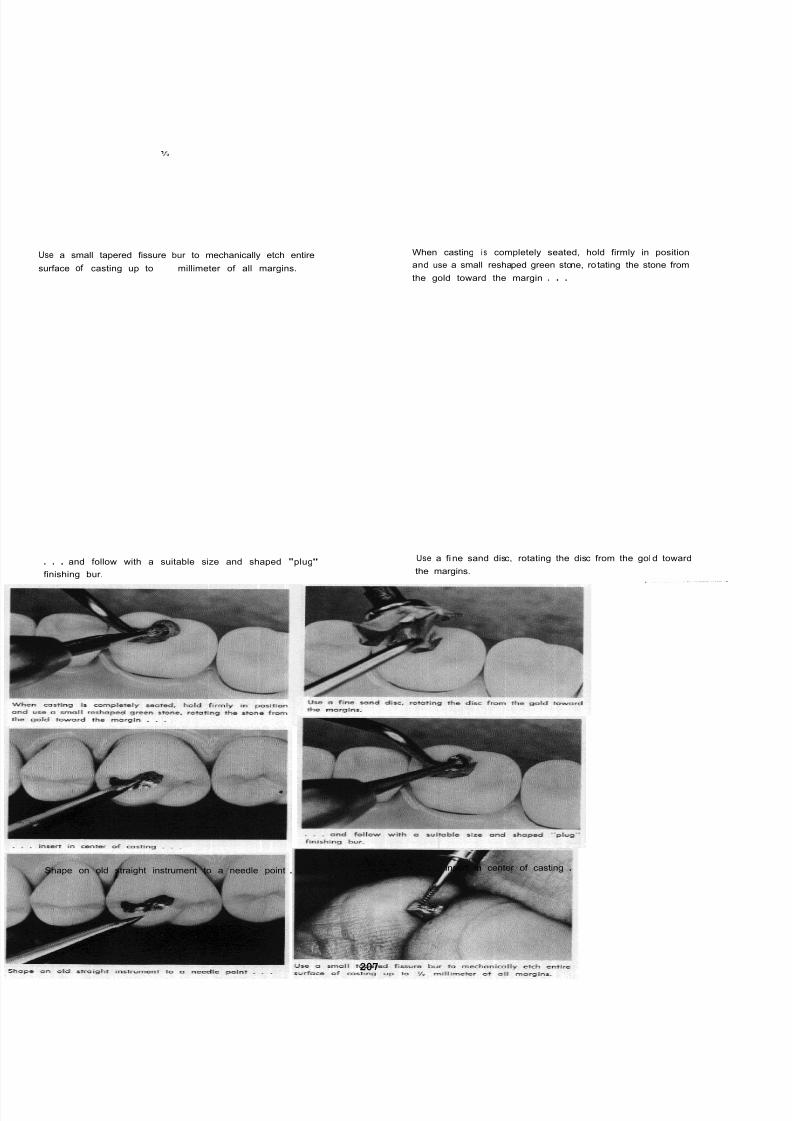
8/11/2019 An Atlas of Cast Gold Procedures
http://slidepdf.com/reader/full/an-atlas-of-cast-gold-procedures 219/270
Use a small tapered fissure bur to mechanically etch entire
surface of casting up to I millimeter of all margins.
When casting i s completely seated, hold firmly in position
and use a small reshaped green stone, rotating the stone from
the gold toward the margin . . .
. . . and follow with a suitable size and shaped "plug"
finishing bur.
Use a fi ne sand disc, rotating the disc from the gol d toward
the margins.
Shape on old straight instrument to a needle point . . . . . . insert in center of casting .
207

8/11/2019 An Atlas of Cast Gold Procedures
http://slidepdf.com/reader/full/an-atlas-of-cast-gold-procedures 220/270
. .and carefully remove.
Cement casting with a retarded mix of cement, hold firmly
in place and disc all margins with a fine cuttle disc.
Refine occlusal anatomy with a small bud bur.
Remove a l l hardened cement and polish grooves with fi
wet pumice applied with a tapered end brush.
Continue palish wi th pumice and rubber cup. Use rubber cup with high polishing agent. Completed restoration.
208
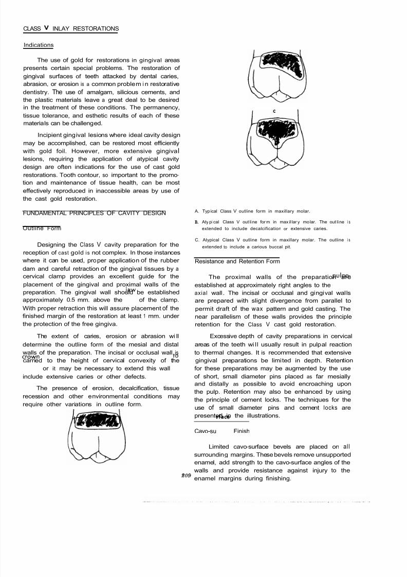
8/11/2019 An Atlas of Cast Gold Procedures
http://slidepdf.com/reader/full/an-atlas-of-cast-gold-procedures 221/270
CLASS V INLAY RESTORATIONS
Indications
The use of gold for restorations in gingival areas
presents certain special problems. The restoration of
gingival surfaces of teeth attacked by dental caries,
abrasion, or erosion is a common problem in restorative
dentistry. The use of amalgam, silicious cements, and
the plastic materials leave a great deal to be desiredin the treatment of these conditions. The permanency,
tissue tolerance, and esthetic results of each of these
materials can be challenged.
Incipient gingival lesions where ideal cavity design
may be accomplished, can be restored most efficiently
with gold foil. However, more extensive gingiva I
lesions, requiring the application of atypical cavity
design are often indications for the use of cast gold
restorations. Tooth contour, so important to the promo-
tion and maintenance of tissue health, can be most
effectively reproduced in inaccessible areas by use of
the cast gold restoration.
A. Typ ical Class V outline form in maxillary molar.
B. Aty pical Class V out line for m in max il lar y molar. The out line i s
FUNDAMENTAL PRINCIPLES OF CAVITY DESIGN
Outline Form extended to include decalcification or extensive caries.
Designing the Class V cavity preparation for the
reception of cast gold i s not complex. In those instances
where it can be used, proper application of the rubber
dam and careful retraction of the gingival tissues by a
cervical clamp provides an excellent guide for the
placement of the gingival and proximal walls of the
preparation. The gingival wall should be established
approximately 0.5 mm. above the jaw of the clamp.
With proper retraction this will assure placement of the
finished margin of the restoration at least 1 mm. under
the protection of the free gingiva.
C. Atypical Class V outline form in maxillary molar. The outline i s
extended to include a carious buccal pit.
Resistance and Retention Form
The proximal walls of the preparation are
established at approximately right angles to the pulpo-
axial wall. The incisal or occlusal and gingival walls
are prepared with slight divergence from parallel topermit draft of the wax pattern and gold casting. The
near parallelism of these walls provides the principle
retention for the Class V cast gold restoration.
The extent of caries, erosion or abrasion wi ll Excessive depth of cavity preparations in cervical
determine the outline form of the mesial and distal areas of the teeth wi ll usually result in pulpal reaction
walls of the preparation. The incisal or occlusal wall is to thermal changes. It is recommended that extensive
carried to the height of cervical convexity of the gingival preparations be limited in depth. Retention
crown or it may be necessary to extend this wall to for these preparations may be augmented by the use
include extensive caries or other defects. of short, small diameter pins placed as far mesially
and distally as possible to avoid encroaching upon
the pulp. Retention may also be enhanced by using
the principle of cement locks. The techniques for the
use of small diameter pins and cement locks are
The presence of erosion, decalcification, tissue
recession and other environmental conditions may
require other variations in outline form.
presented in the illustrations.
Cavo-sudace Finish
I AI
Limited cavo-surface bevels are placed on all
surrounding margins. These bevels remove unsupported
enamel, add strength to the cavo-surface angles of the
walls and provide resistance against injury to the
enamel margins during finishing.
a09

8/11/2019 An Atlas of Cast Gold Procedures
http://slidepdf.com/reader/full/an-atlas-of-cast-gold-procedures 222/270
ARMAMENTARIUM FOR CLASS V PREPARATION AND QIRECT
WAX PATTERN
PREPARATION
LARGE ROUND BUR
MEDIUM SIZE WHEEL SHAPE DIAMOND
TAPER FISSURE BUR
.028 INCH, .024 INCH BI-BEVEL TWIST DRILLS
WHITE POLY STONE
DIRECT WAX PATTERN
NYLON BRISTLES, 020 INCH, .022 INCH, 026 INCH, .027 INCH
WAXING PLIERS
3
HOLLENBACK WAX CARVER
3
EXPLORER
ACETONE
I WAX SPATULA
18 GAUGE HOLLOW SPRUE
INDIRECT IMPRESSION
KERR PERFORATED TRAY METAL
GREEN STICK COMPOUND
HEAVY BODIED ELASTICON AND ACCESSORIES (ref. Chapter 8)
FINISHING AND CEMENTATION
STRIPPING UNIT
HOLDING INSTRUMENT
EGG BURNISHER
SPECIAL POINTED INSTRUMENT (made from old straight instrument.)
SULCI BURLEW WHEEL
LENTULO # 4 PASTE FILLER
FINE SAND AND CUTTLE DISCS
RUBBER CUP AND FINE PUMICE
TIN OXIDE OR CHAULK

8/11/2019 An Atlas of Cast Gold Procedures
http://slidepdf.com/reader/full/an-atlas-of-cast-gold-procedures 223/270
PROCEDURES FOR CLASS V PREPARATION AND DIRECT WA X PATTERN
Caries, decalcification or erosion requiring a ClassV
restora
tion.
Use a large round carbide bur
. . . to remove caries . . .
As an alternate method the wheel-shaped diamond
and establish outline form.
. . can be used to establish outline form.
21 1

8/11/2019 An Atlas of Cast Gold Procedures
http://slidepdf.com/reader/full/an-atlas-of-cast-gold-procedures 224/270
Use a tapered fissure bur . . . . . . to establish the box form.
With a sharpened lead pencil, locate the position of pin
holes which will be favorable to the pulp.
Use a small bi-beveled twist drill . . .
. . . to drill the distal . . . . . . and mesial pin holes. Small pins are used when add
retention i s required. The pins only need to be h ~
1 m
long. The preparation here illustrated would not require t
use of pins.

8/11/2019 An Atlas of Cast Gold Procedures
http://slidepdf.com/reader/full/an-atlas-of-cast-gold-procedures 225/270

8/11/2019 An Atlas of Cast Gold Procedures
http://slidepdf.com/reader/full/an-atlas-of-cast-gold-procedures 226/270
Add add it io nal mol ten wa x . . . . . . and build to excess contour.
Use a suitable warmed plastic instrument, to establish con-
tour and marginal refinement.
Att ach a right ang le explorer to the center of pattern . . .
Smooth the pattern with cotton and acetone.
. . . and carefully remove from preparation.
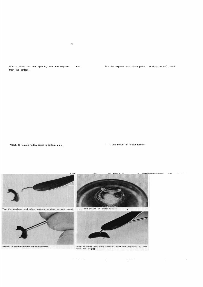
8/11/2019 An Atlas of Cast Gold Procedures
http://slidepdf.com/reader/full/an-atlas-of-cast-gold-procedures 227/270
With a clean hot wax spatula, heat the explorer h inch
from the pattern.
Attach 18 Gauge hollow sprue to pattern . . .
Tap the explorer and allow pattern to drop on soft towel.
. . . and mount on crater former.
215
. .. .... , . . , . .... ..
_____I__.. , - .
- .

8/11/2019 An Atlas of Cast Gold Procedures
http://slidepdf.com/reader/full/an-atlas-of-cast-gold-procedures 228/270
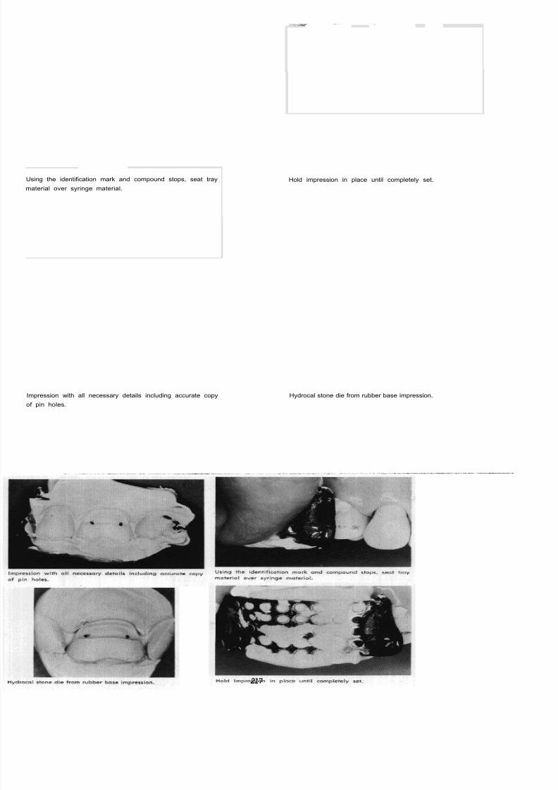
8/11/2019 An Atlas of Cast Gold Procedures
http://slidepdf.com/reader/full/an-atlas-of-cast-gold-procedures 229/270
Using the identification mark and compound stops, seat tray
material over syringe material.
Impression with all necessary details including accurate copy
of pin holes.
Hold impression in place until completely set.
Hydrocal stone die from rubber base impression.
217

8/11/2019 An Atlas of Cast Gold Procedures
http://slidepdf.com/reader/full/an-atlas-of-cast-gold-procedures 230/270
Clean dry casting, ready for inspection.
Use a Number 2 round bur to counter -sink pin holes.
Remove sprue handle and smooth casting up to margin.
With a
strip for 5 seconds.
round bur, remove any nodules or roughness
Trial seat costing. If not completely seated, strip ano
5 seconds.
Seat casting with mallet force, hold in position and burn
all accessible margins . . .

8/11/2019 An Atlas of Cast Gold Procedures
http://slidepdf.com/reader/full/an-atlas-of-cast-gold-procedures 231/270

8/11/2019 An Atlas of Cast Gold Procedures
http://slidepdf.com/reader/full/an-atlas-of-cast-gold-procedures 232/270
PROCEDURES FOR FINISHING AND CEMENTATION
. . . and*in
preparation. Cement locks made in this way
will add to the retention of the restoration.
Use a Lentulo Number 4 paste filler in a contra angle hand
piece . . .
. . . to carry cement to bottom of pin holes. Apply cement to preparation and casting and seat wit
mallet force.
Hold casting firmly in place and disc all accessible margins
with a fine cuttle disc.
Remove all hardened cement and palish casting with fin
wet pumice in a rubber cup.
220

8/11/2019 An Atlas of Cast Gold Procedures
http://slidepdf.com/reader/full/an-atlas-of-cast-gold-procedures 233/270
Estoblish high polish with tin oxide or chaulk. Finished restoration.
221

8/11/2019 An Atlas of Cast Gold Procedures
http://slidepdf.com/reader/full/an-atlas-of-cast-gold-procedures 234/270

8/11/2019 An Atlas of Cast Gold Procedures
http://slidepdf.com/reader/full/an-atlas-of-cast-gold-procedures 235/270
TOP PLATE
Class V rubber base impression with nylon bristles.
BOTTOM PLATE
Removing Class V casting with pointed instrument.
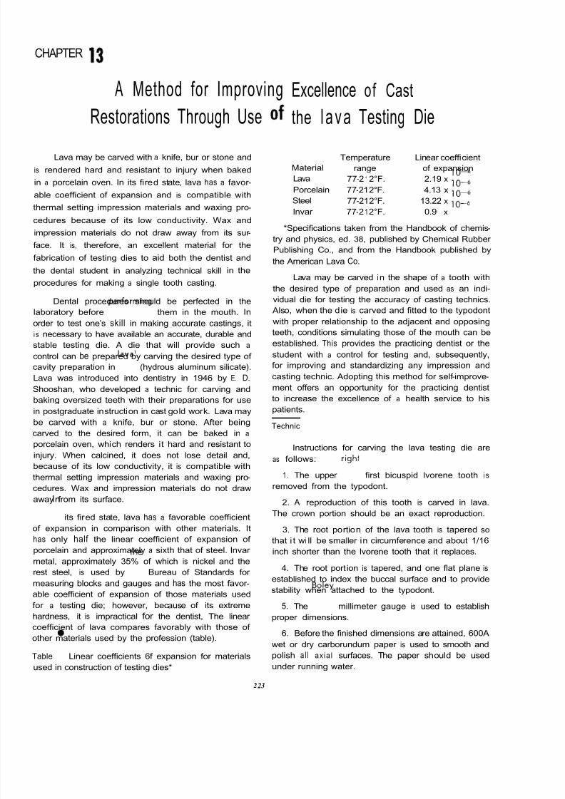
8/11/2019 An Atlas of Cast Gold Procedures
http://slidepdf.com/reader/full/an-atlas-of-cast-gold-procedures 236/270
CHAPTER 3
A Method for Improving
Restorations Through Use
Lava may be carved with a knife, bur or stone and
is rendered hard and resistant to injury when baked
in a porcelain oven. In its fired state, lava has a favor -
able coefficient of expansion and is compatible with
thermal setting impression materials and waxing pro-
cedures because of its low conductivity. Wax and
impression materials do not draw away from its sur -
face. It is, therefore, an excellent material for the
fabrication of testing dies to aid both the dentist and
the dental student in analyzing technical skill in the
procedures for making a single tooth casting.
Dental procedures should be perfected in the
laboratory before performing them in the mouth. In
order to test one’s skill in making accurate castings, it
i s necessary to have available an accurate, durable and
stable testing die. A die that will provide such a
control can be prepared by carving the desired type of
cavity preparation in lava’ (hydrous aluminum silicate).
Lava was introduced into dentistry in 1946 by E. D.
Shooshan, who developed a technic for carving and
baking oversized teeth with their preparations for use
in postgraduate instruction in cast gold work. Lava may
be carved with a knife, bur or stone. After being
carved to the desired form, it can be baked in a
porcelain oven, which renders it hard and resistant to
injury. When calcined, it does not lose detail and,
because of its low conductivity, it is compatible with
thermal setting impression materials and waxing pro-
cedures. Wax and impression materials do not draw
away from its surface.
in its fired state, lava has a favorable coefficient
of expansion in comparison with other materials. It
has only half the linear coefficient of expansion of
porcelain and approximately a sixth that of steel. lnvar
metal, approximately 35% of which is nickel and therest steel, is used by the Bureau of Standards for
measuring blocks and gauges and has the most favor -
able coefficient of expansion of those materials used
for a testing die; however, because of its extreme
hardness, it is impractical for the dentist, The linear
coefficient of lava compares favorably with those of
other materials used by the profession (table).
Table Linear coefficients 6f expansion for materials
used in construction of testing dies*
Excellence of Cast
the l a va Testing Die
Temperature Linear coefficient
Material range of expansion
Lava 77-212°F. 2.19 x 10 6
Porcelain 77-21 2°F. 4.13 x 10 6
Steel 77-21 2°F. 13.22 x 10 6
lnvar 77-212°F. 0.9 x 10 6
*Specifications taken from the Handbook of chemis-
try and physics, ed. 38, published by Chemical Rubber
Publishing Co., and from the Handbook published by
the American Lava Co.
Lava may be carved in the shape of a tooth withthe desired type of preparation and used as an indi-
vidual die for testing the accuracy of casting technics.
Also, when the die is carved and fitted to the typodont
with proper relationship to the adjacent and opposing
teeth, conditions simulating those of the mouth can be
established. This provides the practicing dentist or the
student with a control for testing and, subsequently,
for improving and standardizing any impression and
casting technic. Adopting this method for self -improve-
ment offers an opportunity for the practicing dentist
to increase the excellence of a health service to his
patients.
Technic
Instructions for carving the lava testing die are
as follows:
1 . The upper righi first bicuspid lvorene tooth is
removed from the typodont.
2. A reproduction of this tooth is carved in lava.
The crown portion should be an exact reproduction.
3. The root portion of the lava tooth is tapered so
that i t wi ll be smaller in circumference and about 1/16
inch shorter than the lvorene tooth that it replaces.
4. The root portion is tapered, and one flat plane is
established to index the buccal surface and to provide
stability when attached to the typodont.
5. The Boley millimeter gauge is used to establish
proper dimensions.
6. Before the finished dimensions are attained, 600A
wet or dry carborundum paper is used to smooth and
polish a l l axia l surfaces. The paper should be used
under running water.
223

8/11/2019 An Atlas of Cast Gold Procedures
http://slidepdf.com/reader/full/an-atlas-of-cast-gold-procedures 237/270
7. While the carborundum paper i s being used, the
lava should be dried frequently and examined for
scratches. A final luster is obtained by rubbing the
lava carving briskly over the surface of a soft cloth.
(Disks or a rubber cup with polishing agents are con-
tra indicated.)
8. The lava tooth carving is fitted into the typodont
with the contact areas in their proper relationship. (At
this point, the root of the lava carving will fit quite
loosely in the typodont.)
mineral or engine oil.
9. The socket in the typodont is lubricated with
10. The root portion of the lava tooth is lubricated
generously with Vaseline.
11. Self -curing plastic is mixed in a dappen
until thick.
12. A portion of this plastic is placed in the
socket of the typodont.
13. The lava tooth is placed in the socket
baked in a porcelain furnace to establish maximu
hardness. A small, cup-shaped holder i s construct
from alundum cement2 to hold the tooth upright durin
firing. The holder is made by mixing alundum powd
with water to form a thick paste that can be molde
into the desired shape and then hardened by carryi
it up to 2400°F. in the porcelain furnace.
The lava tooth in the holder is placed in a co
oven. The furnace is heated slowly to 2350°F. Aft
maintaining the temperature at 2350°F. for 10 minute
the oven i s turned off and, with the door opened,
allowed to cool to 200°F. before removing the die.
If these directions are followed carefully, th
sharpness of margins and internal details that ha
and
pressed in position. In the initial stages of hardening,
the lava tooth and the plastic shim are freed. This must
be done before the plastic hardens completely to be
certain that both the shim and lava tooth can be easily
removed from the typodont.
been established in the preparation will be retaine
The lava die will expand approximately 1.8% of
volume during the baking, which will necessita
repositioning the die in the typodont by constructin
a new plastic shim.
dish
root
After bakina. a careful examination should
Making the Preparation in the l ava Tooth
The greatest value of the testing di e w i l l be
realized only if the preparation embodies all the basic
requirements of sound cavity preparation. The MOD
onlay type restoration i s employed frequently for
restoring the posterior teeth. Since the intricacy of thepreparation design requires maximum attention to
detail and a more exacting technic to produce an
accurately fitting casting, the MOD onlay is suggested
for making an accurate analysis of results. Although
the design of this particular cavity preparation varies,
it must embody certain definite principles. There should
be occlusal and proximal box forms with definite,
sharp cavosurface margins, and it should be devoid of
any internal or external undercuts.
The cavity preparation may be made with instru-
ments similar to those employed for preparing natural
teeth. Plaincut, tapered fissure burs are recommended
to establish the occlusal and proximal box forms. The
final finish of the internal detail is accomplished best
with razor -sharp hand instruments. The occlusal re-
duction, contrabevels and gingival bevels are made
with a reshaped white polystone used wet. The axial
flares are established with a razor -sharp No. 15
straiaht chisel or a Bard-Parker knife with a No. 11
. .
made again to detect any internal or external undercuor lack of sharpness of the cavosurface margins.
minor corrections should be necessary, a smooth t
pered diamond stone lubricated with glycerin or
tapering fissure carbide bur lubricated with olive o
and kerosene may be used to remove internal unde
cuts. Wet 0 Dry discs lubricated with glycerin can b
employed to remove external undercuts and to defin
the cavosurface margins of the flares.
The result is an adequate die of a hard, durab
substance that will provide a control for testing th
accuracy of any technic that the operator may wish
employ. By using such a control, the dentist or studecan make a critical analysis of his results to provide th
means for standardization and self -improvement. T
fabrication of the lava testing die and all of the pr
cedures incidental to making a test casting are base
on acceptable limits of clinical accuracy.
Procedures for Use of Testing Die
When the operator wishes to test his accuracy
fabricating a wax pattern and subsequently reprodu
ing it in cast gold, the following steps may be used
1. A wax pattern is made directly in the die usiany desired technic. It is suggested that the results
this first step be judged by examination of all surfac
and margins of the pattern with magnification in th
presence of adequate incandescent lighting. The co
struction of an accurate wax pattern is one of the mo
exacting steps in making a single tooth casting..
blade and No. handle. Care must be exercised since
the lava is much softer than enamel in i ts unbaked
state. The lava tooth with its completed preparation is
2. The completed pattern is sprued and remov
carefully from the die, and it is attached to the crat
former.
22 5
8/11/2019 An Atlas of Cast Gold Procedures
http://slidepdf.com/reader/full/an-atlas-of-cast-gold-procedures 238/270
3. The pattern i s invested, burned out and the
casting made by the specific technic to be tested.
4. The casting is cleaned by alternately scrubbing
it with a toothbrush and boiling it in a 50% solution
of hydrochloric acid.
5. The dry casting i s examined, and any visible
roughness or nodules are removed with a small,
round bur.
6. The casting is etched. Etching may be accom-plished by one of the following methods.
a. The preferred method is to etch the casting in
a stripping unit3 (reverse electrolysis) for 10 seconds.
The casting i s tried on the die, and the procedure is
repeated, if necessary, until the casting seats perfectly.
The maximum stripping time is 50 seconds; this amount
of stripping i s within clinically acceptable limits.
b. The margins and outer surfaces of the casting
are protected with a coating of wax and then immersed
for four to five minutes in a fresh solution of aqua
regia.
c. The entire internal surface of the casting is
etched to within 1 mm. of the surrounding margins
with a suitable bur.
7. The casting is seated on the die without burnish-
ing or finishing and is examined for accuracy of fit.
If the casting fits the testing die accurately, i t may be
assumed that the technics used are clinically acceptable.
If, however, the casting does not fulfill this require-
ment, it will be necessary for the operator to analyze
critically each step in the technic employed. By process
of elimination, it wil l be possible to discover errors.
The errors should then be corrected, and a procedure
standardized that wi ll give uniformly acceptable results.
Indirect Impression Technics
With the testing die seated in proper position in
the typodont, conditions similar to those in the mouth
are produced with the exception of interfering gingival
tissues. Any indirect impression technic may be em-
ployed and tested. If the operator wishes to alter a
part of a technic, he has excellent control for accom-
plishing this.
Conclusion
The lava testing die provides an excellent means
for critically analyzing technical skills in the procedures
for making castings. It has proved valuable for en-
hancing the skill and knowledge of students and has
aided dentists in improving the excellence of their
health service to patients.
1. American Lava Company (subsidiary of Minnesota Mining and Manu-
facturing Company].
2. Braun ChemicalCompany.
3. A. L. Engelhardt Company, Los Angeles

8/11/2019 An Atlas of Cast Gold Procedures
http://slidepdf.com/reader/full/an-atlas-of-cast-gold-procedures 239/270
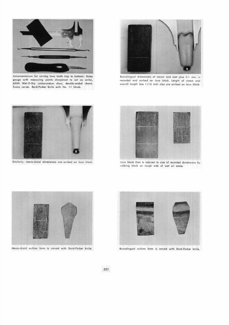
8/11/2019 An Atlas of Cast Gold Procedures
http://slidepdf.com/reader/full/an-atlas-of-cast-gold-procedures 240/270

8/11/2019 An Atlas of Cast Gold Procedures
http://slidepdf.com/reader/full/an-atlas-of-cast-gold-procedures 241/270
Buccolingual contour and tapered root forms are refined while
retaining overall dimensions of crown portion of tooth.
Mesio-distal view of completed axial surfaces of carving. This
is accomplished by use of 600A wet or dry paper used wet
ond followed by rubbing briskly on piece of soft cloth.
Armamentarium for constructing removable plastic shim are
[left to right) spatula, self -curing liquid and powder, eye-
dropper, dappen dish with powder, engine or minerol oil and
VaseIIne.
Mesio-distal contour and tapered root forms are refined furthe
while retaining overoll dimensions of crown portion. Overa
dimensions are left until final refinement of carving.
Bucco lingual view of axial surfaces of carving. Note that fla
plane or facet i s carved on buccal surface of root.
Socket of typodont i s lubricated generously with mineral o
engine oil.
228
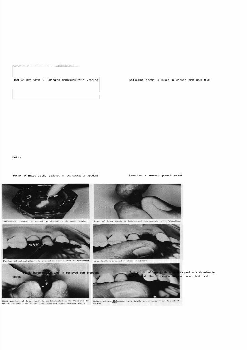
8/11/2019 An Atlas of Cast Gold Procedures
http://slidepdf.com/reader/full/an-atlas-of-cast-gold-procedures 242/270
Root of lava tooth i s lubricated generously wi th Vaseline Self -curing plastic i s mixed in dappen dish until thick.
Portion of mixed plastic i s placed in root socket of typodont
Before plastic hardens, lava tooth i s removed from typodont
socket.
Lava tooth is pressed in place in socket
Root portion of lava tooth i s re-lubricated with Vaseline to
make certain that it can be removed from plastic shim.
229

8/11/2019 An Atlas of Cast Gold Procedures
http://slidepdf.com/reader/full/an-atlas-of-cast-gold-procedures 243/270

8/11/2019 An Atlas of Cast Gold Procedures
http://slidepdf.com/reader/full/an-atlas-of-cast-gold-procedures 244/270
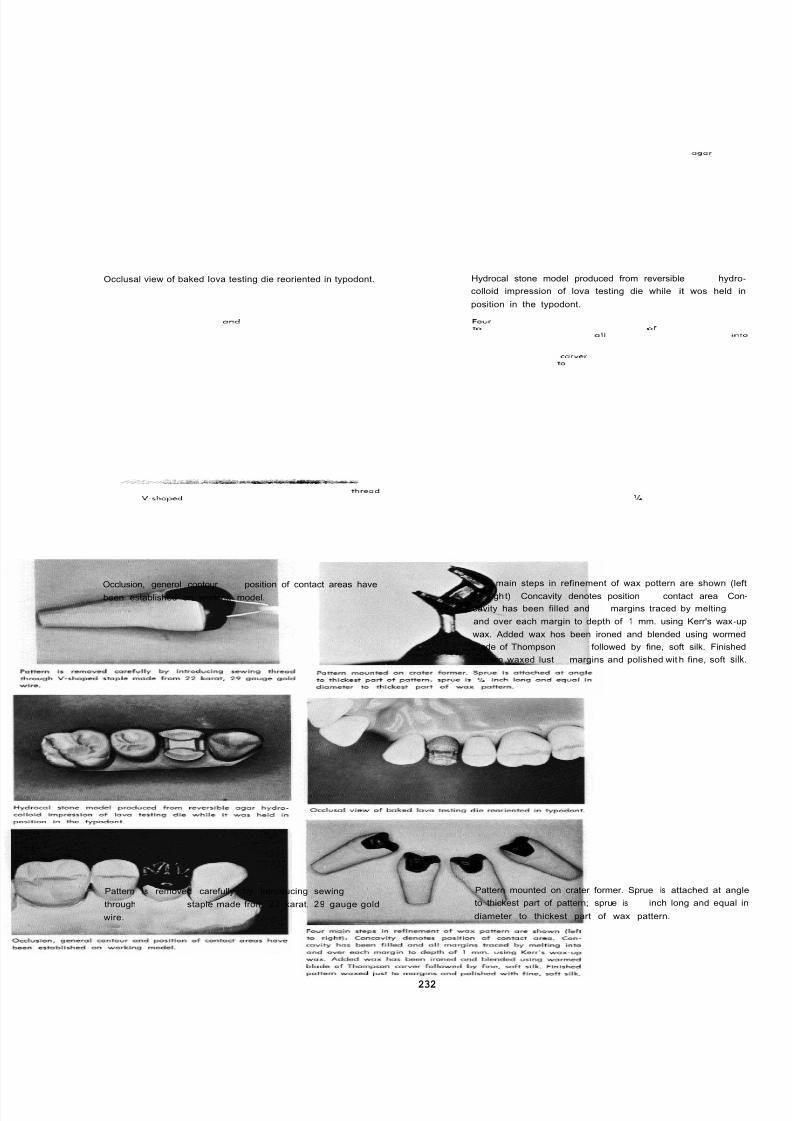
8/11/2019 An Atlas of Cast Gold Procedures
http://slidepdf.com/reader/full/an-atlas-of-cast-gold-procedures 245/270
Occlusal view of baked Iova testing die reoriented in typodont. Hydrocal stone model produced from reversible agar hydro
colloid impression of lova testing die while it wos held
position in the typodont.
Occlusion, generol contour and position of contact areas have
been established on working model.
Pattern i s removed carefully by introducing sewing thread
through V shaped staple made from 22 karat, 29 gauge gold
wire.
Four main steps in refinement of wax pottern are shown (le
to righ t) Concavity denotes position of contact area Co
cavity has been filled and 11 margins traced by melting in
and over each margin to depth of 1 mm. using Kerr's wax-u
wax. Added wax hos been ironed and blended using worme
blade of Thompson corver followed by fine, soft silk. Finishe
pattern waxed lust to margins and polished wit h fine, soft sil
Pattern mounted on crater former. Sprue is attached at ang
to thickest part of pattern; sprue is inch long and equal
diameter to thickest part of wax pattern.
232
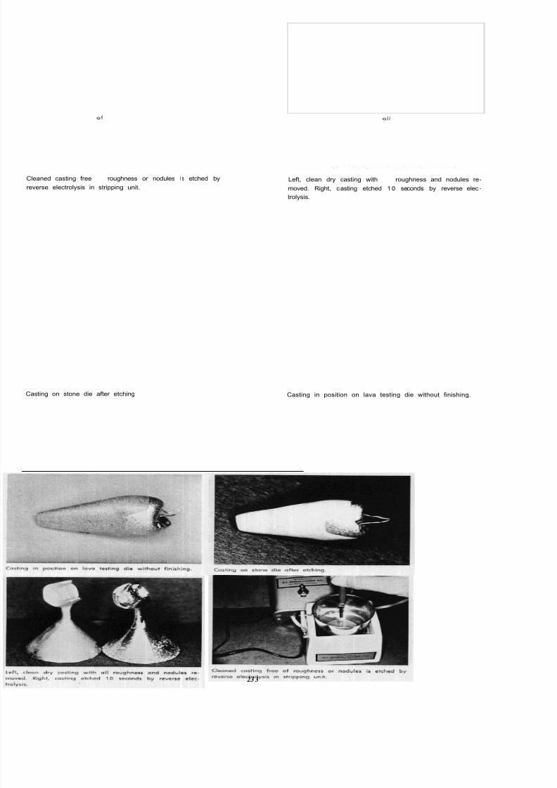
8/11/2019 An Atlas of Cast Gold Procedures
http://slidepdf.com/reader/full/an-atlas-of-cast-gold-procedures 246/270
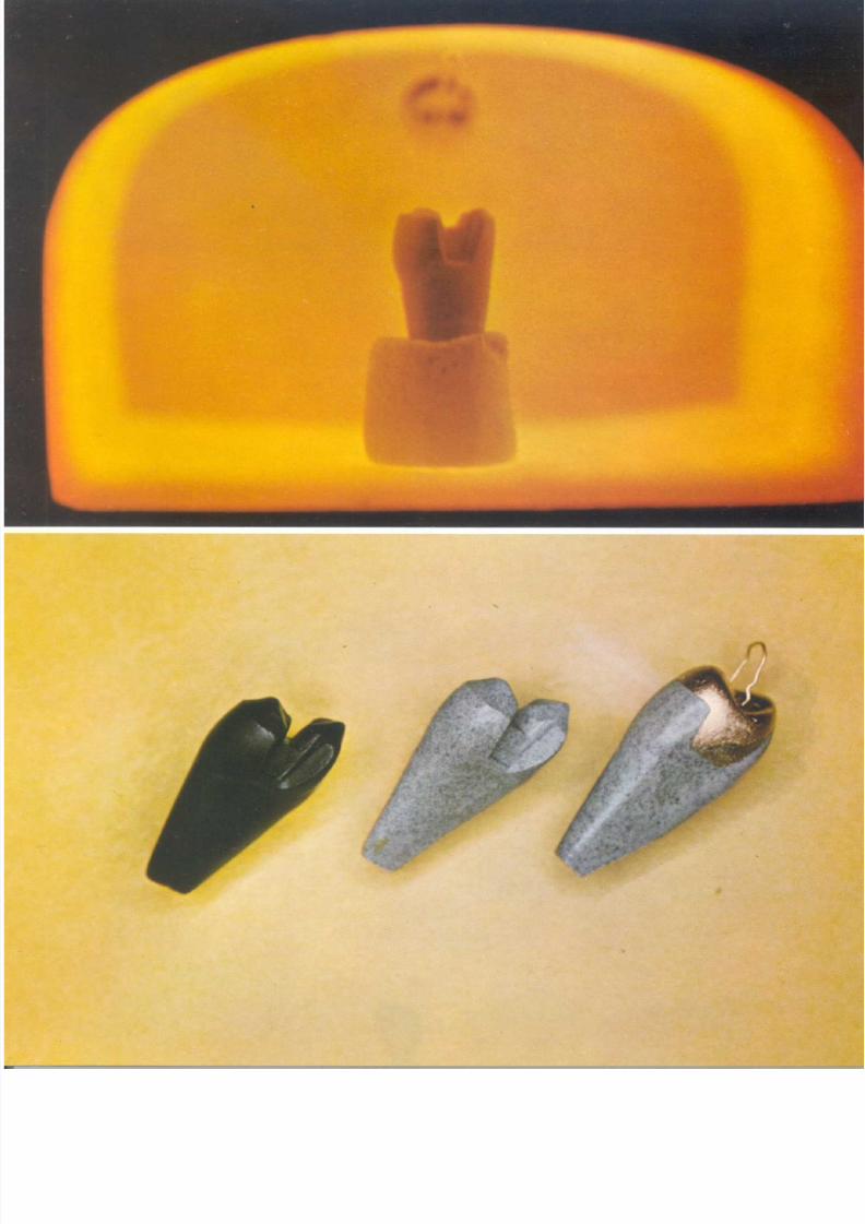
8/11/2019 An Atlas of Cast Gold Procedures
http://slidepdf.com/reader/full/an-atlas-of-cast-gold-procedures 247/270

8/11/2019 An Atlas of Cast Gold Procedures
http://slidepdf.com/reader/full/an-atlas-of-cast-gold-procedures 248/270
TOP PLATE
Baking Lava Testing die in porcelain furnace.
BOTTOM PLATE
Unbaked and baked lava testing die with test casting.

8/11/2019 An Atlas of Cast Gold Procedures
http://slidepdf.com/reader/full/an-atlas-of-cast-gold-procedures 249/270
CH APTER 4
Tooth Form and Function*
A finished cast gold restoration should embody all
the requirements of physiologic tooth form and func-tion. To accomplish this, axial contours, embrasures
and marginal ridge relationships, shape size and po-
sition of contact areas, and functional occlusal anatomy
must first be developed in the wax pattern.
Obviously, it is not within the scope of this Atlas
to encompass all of the biologic and physiologic con-
siderations within the broad subject of articulation and
occlusion. To do so would include a review of the
anatomy of the temporomandibular joint, the muscles
of mastication, the ligaments which limit the action of
the mandible, and a comprehensive discussion of the
synergy of muscle action in a chewing stroke.
It is the intent however, to outline the requirements
of physiologically compatible tooth form and to
describe in detail occlusal contact, cusp-fossa and
cusp-ridge relationships of the working surfaces of the
maxillary and mandibular teeth in function. These
features must be developed in the wax pattern on the
working model and refined on the master die.
PHYSIOLOGIC TOOTH CONTOURS
In the restoration of lost tooth structure it i s
essential that the operator have a thorough knowledge
of the biologic and physiologic relationships of the
individual teeth to each other and to their investing
and supporting tissues.
Teeth possess physiologic curvatures which
supplement natural mouth hygiene and provide a
degree of protection to the periodontium by preventing
food impingement against soft tissues. All tooth crowns
possess a general height of contour on the labial or
buccal and lingual surfaces. Groups of teeth exhibit
similar characteristic variations in the location of their
general height of contours. They are the maxillary and
mandibular anterior teeth, the maxillary posterior
teeth, and the mandibular posterior teeth.
The general height of contours on the labial and
lingual surfaces of all anterior teeth are located in thegingival third area. The general height of contours on
the buccal and lingual surfaces of the maxillary pos-
terior teeth are located in the gingival third area. The
height of contours are more prominent on the lingual
surfaces of the maxillary posterior teeth than on the
buccal surfaces. The general height of contours of
the mandibular posterior teeth are located in the
gingival third areas of their buccal surfaces and in the
middle third areas of their lingual surfaces. The height
of contours are more prominent on the buccal surfaces
of the mandibular posterior teeth than on their lingualsurfaces.
*The informotion contained in this chapter is o resume' of one section of a
report on on applied clinical and loborotory investigation in the field
of tooth form and functional occlusion. The study has been conducted
within the department of Operative Dentistry, University of Southern
Colifornio by Dr. Rex Ingroham.
235
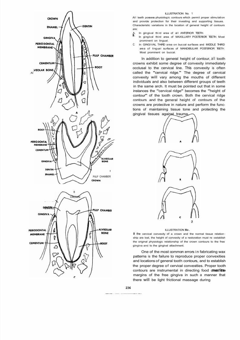
8/11/2019 An Atlas of Cast Gold Procedures
http://slidepdf.com/reader/full/an-atlas-of-cast-gold-procedures 250/270
AI
PERIODONTA
PULP CHAMBER
B
CROWN
ENAMEL
ILLUSTRATION No. 1
Al l teeth possess physiolog ic contours which permi t proper stimulation
and provide protection for their investing and supporting tissues.
Characteristic variations in the location of general height of contours
are:
A. In gingival thi rd area of al l ANTERIOR TEETH.
B. In gingival thi rd area of MAXILLARY POSTERIOR TEETH. Mos
prominent on lingual.
C. In GINGIVAL THIRD area on buccal surfaces and MIDDLE THIRD
area o f li ngua l surfaces of MANDIBULAR POSTERIOR TEETH
Most prominent on buccal.
In addition to general height of contour, a l l toothcrowns exhibit some degree of convexity immediately
occlusal to the cervical line. This convexity is often
called the "cervical ridge." The degree of cervica
convexity will vary among the mouths of differen
individuals and also between different groups of teeth
in the same arch. It must be pointed out that in some
instances the "cervical ridge" becomes the "height o
contour " of the tooth crown. Both the cervical ridge
contours and the general height of contours of the
crowns are protective in nature and perform the func
tions of maintaining tissue tone and protecting the
gingival tissues against trauma.
ILLUSTRATION No.
If the cervical convexity of a crown and the normal tissue relation
ship are lost, the height of convexity of a restoration must re -establisthe original physiologic relationship of the crown contours to the free
gingiva and to the gingival attachment.
One of the most common errors in fabricating wax
patterns is the failure to reproduce proper convexities
and locations of general tooth contours, and to establish
the proper degree of cervical convexities. Proper tooth
contours are instrumental in directing food over the
margins of the free gingiva in such a manner tha
there will be light frictional massage during mastica
236
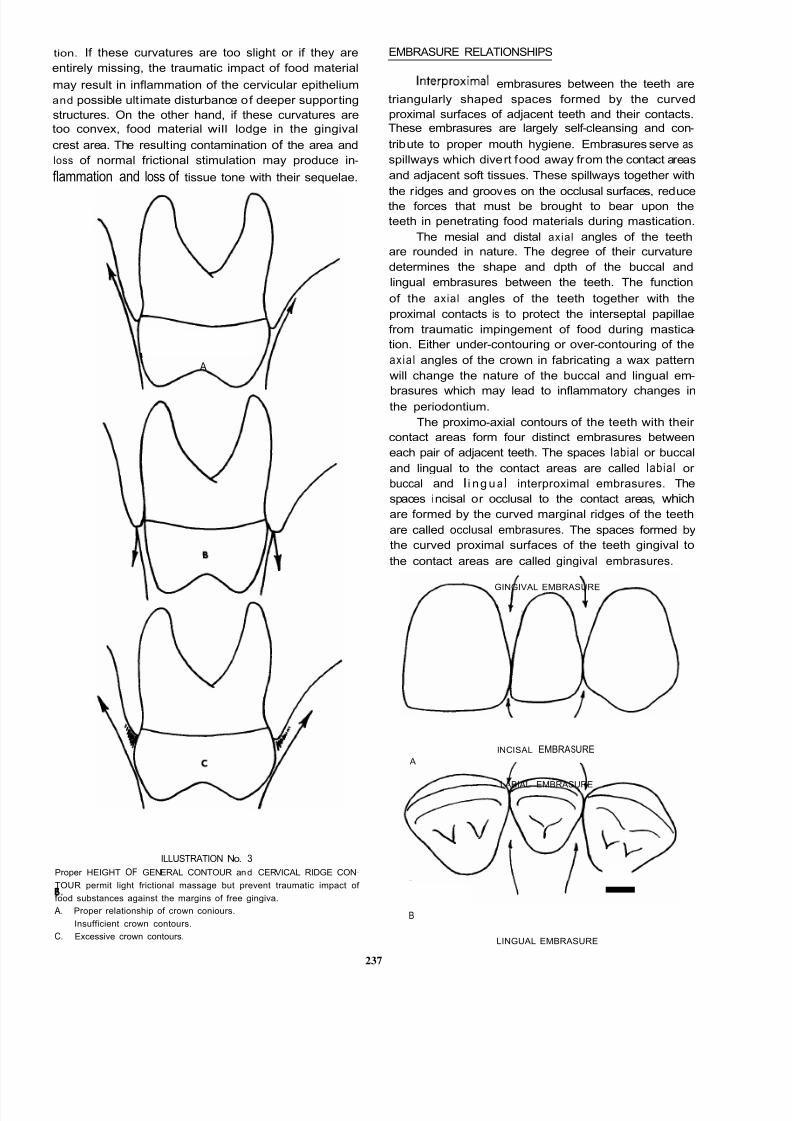
8/11/2019 An Atlas of Cast Gold Procedures
http://slidepdf.com/reader/full/an-atlas-of-cast-gold-procedures 251/270
tion. If these curvatures are too slight or if they are
entirely missing, the traumatic impact of food material
may result in inflammation of the cervicular epithelium
and possible ult imate disturbance of deeper supporting
structures. On the other hand, if these curvatures are
too convex, food material will lodge in the gingival
crest area. The resulting contamination of the area and
loss of normal frictional stimulation may produce in-
flammation and loss of tissue tone with their sequelae.
I A
ILLUSTRATION No. 3
Proper HEIGHT OF GENERAL CONTOUR and CERVICAL RIDGE CON-
TOUR permit light frictional massage but prevent traumatic impact of
food substances against the margins of free gingiva.
A.
8. Insufficient crown contours.
C. Excessive crown contours.
Proper relationship of crown coniours.
EMBRASURE RELATIONSHIPS
Interproximal embrasures between the teeth are
triangularly shaped spaces formed by the curved
proximal surfaces of adjacent teeth and their contacts.
These embrasures are largely self -cleansing and con-
tribute to proper mouth hygiene. Embrasures serve as
spillways which divert food away from the contact areas
and adjacent soft tissues. These spillways together with
the ridges and grooves on the occlusal surfaces, reducethe forces that must be brought to bear upon the
teeth in penetrating food materials during mastication.
The mesial and distal axial angles of the teeth
are rounded in nature. The degree of their curvature
determines the shape and dpth of the buccal and
lingual embrasures between the teeth. The function
of the axial angles of the teeth together with the
proximal contacts is to protect the interseptal papillae
from traumatic impingement of food during mastica-
tion. Either under -contouring or over -contouring of the
axial angles of the crown in fabricating a wax pattern
will change the nature of the buccal and lingual em-
brasures which may lead to inflammatory changes inthe periodontium.
The proximo-axial contours of the teeth with their
contact areas form four distinct embrasures between
each pair of adjacent teeth. The spaces labial or buccal
and lingual to the contact areas are called labial or
buccal and Ii ng u a I interproximal embrasures. The
spaces incisal or occlusal to the contact areas, which
are formed by the curved marginal ridges of the teeth
are called occlusal embrasures. The spaces formed by
the curved proximal surfaces of the teeth gingival to
the contact areas are called gingival embrasures.
GINGIVAL EMBRASURE
INCISAL EMBRASURE A
LABIAL EMBRASURE
-B
LINGUAL EMBRASURE
237

8/11/2019 An Atlas of Cast Gold Procedures
http://slidepdf.com/reader/full/an-atlas-of-cast-gold-procedures 252/270
,GINGIVAL EMBRASURE
,BUCCALEYBRASURE
LINGUAL EMBRASURE
ILLUSTRATION No. 4
Embrasure relationships-
anterior an d posterior teeth.
A. Gingival embrasures wider and deeper th an inci salombraruros.
B. Lingual embrasures wider and deeper than labialambrosures.
C. Gingival embrasureswidor
and deeper than occlusal embrasures.
D. lingual embrasures wider anddaeper
than buccal embrasures.
In general, the lingual interproximal embrasures
are wider and deeper than the buccal embrasures. This
variation in embrasure form is created by the convexity
of the lingual surfaces of the teeth and the accentuated
mesial and distal bucco-axial angles of the teeth. The
normal position of the contact areas between the teeth
in an axial relationship creates considerably largergingival embrasures than occlusal embrasures. The
nature of the contact areas and the interproximal
cc3mCORRECT
embrasures vary in degree with the form, alignment,
and size of the individual teeth in each mouth. Both
the embrasure form and contact areas when normal,
protect the gingival tissues from frictional trauma and
permit proper tissue stimulation.
MARGINAL RIDGE RELATIONSHIPS
When fabricating a wax pattern on the working
model, the marginal ridges of the pattern should be
established at uniform heights with adjacent margina
ridges. This relationship is necessary to provide the
most efficient spillways for the deflection of food
substances. In some instances it is necessary to reshape
a cusp of an opposing tooth to accomplish this. It wil
be observed that in many mouths the occlusal em-
brasures become progressively deeper toward the
posterior part of the mouth. This occurs a t the expense
to the gingival embrasures. However, this gradua
decrease in the size of the gingival embrasures
between the posterior teeth is partially accounted for
by the progressively increasing occluso-gingival dimen
sion of the contact areas and the progressively shorter
second and third molar crowns. It must be pointed outhat reduction of occlusal embrasures due to abrasion
and wear of the marginal ridges of the teeth is often
the cause of food impaction.
CORRECI INCORRECT
mm
INCORRECT INCORRECT
ILLUSTRATION No. 6
Marglnal
ridge relatlonrhipr.
CONTACT AREAS
When newly erupted teeth throughout the mouth
come into their proper relationships mesio-distally
points of contact are established between their unworn
curved proximal surfaces. The more convex interproxi
mal surfaces of the anterior teeth present "marble like'
contacts in contrast to the broader appearance of the
contacting relationships of the less convex surfaces o
the bicuspid and molar teeth. Physiologic wear how
ever, soon changes these so-called "contact points" to
actual "areas of contact." While the areas of contac
between the anterior teeth tend to remain confined
normal physiologic wear resulting from the rubbing
INC0 RECT
@
E m
INCORRECT
ILLUSTRATION No. 5
Embrasuro
rolatlonships.
8

8/11/2019 An Atlas of Cast Gold Procedures
http://slidepdf.com/reader/full/an-atlas-of-cast-gold-procedures 253/270
together of adjacent teeth produces progressively
larger areas of contact between the bicuspid and molar
teeth. It is obvious of course, that tooth form (square,
tapering, or ovoid) and the alignment of the teeth in
the arches are also factors which determine both the
position and the dimensions of the contact areas.
The purpose of the contact relationships between
adjacent teeth in the arches is twofold. This relationship
serves both to stabilize the dental arches by the
combined support of the individual teeth and toprevent the impingement of food material on inter -
septal tissues between the teeth.
One school of thought teaches that when restoring
proximal tooth surfaces, restorations should reproduce
"point contacts" characteristic of newly erupted teeth.
Proximal wear is usually accompanied by occlusal wear
which results in an increased dimension of the occlusal
table. Occlusal surfaces of this nature require greater
forces for the diminution of fibrous food substances.
This in turn increases the tendency to wedge food
between the contact areas. I t would therefore appear
illogical that the areas of contact between these teeth
be restored to their original form and size present atthe time of eruption. On the other hand excessive
proximal wear, particularly in patients of advanced age,
may create contact areas of greatly increased dimen-
sions. It would be equally inadvisable to reproduce
excessively large contact areas in these instances. Large
flat areas of contact essentially change the nature of
the embrasures between the teeth. In such instances,
the embrasures may no longer function as efficient
spillways for directing food away from the contact area
and the adjacent underlying tissues.
A
C
ILLUSTRATION No. 7
Contact relationships of posterior teeth.
A.
8. Broad flat contact anas resulting from excessive wear.
C.
Point or marble-like contact areas present at time of eruption.
Typical contact areas resulting from the usual amount of wear
observed in a patient of middle age.
It is imperative that the existing conditions in
each mouth relative to contact areas and embrasure
contours be carefully studied before approaching the
restoration of involved tooth surfaces. It is suggestedthat a compromise be made between restoring proximal
tooth surfaces to their original contour with point
contact relationships and to excessively worn and
flattened surfaces with greatly increased dimensions
of the contact area. Other factors which should be
considered in determining the size and dimensions
of contact areas are the changes that have occurred in
the periodontium of the individual patient. The height,
the bucco-lingual dimension and the contour of the
investing and supporting tissues must be studied
radiographically and visually to determine the most
favorable size, shape and position of the contact areas.
A composite description of what is considered tobe physiologically compatible contact and embrasure
relationships between both anterior and posterior teeth
in the maxillary and mandibular arches are described
and illustrated.
The following section will serve as a laboratory
guide for establishing contact and embrasure relation-
ships of individual wax patterns on the working model
for cast gold restorations in any area of the mouth.
To describe the relative position and shape of the
contact areas throughout the mouth, it is necessary to
view the teeth in their arches from both an incisal or
occlusal and a l ab ia l or buccal direction.
CONTACT AND EMBRASURE RELATIONSHIPS
Maxillary Teeth
An incisal view shows the contact areas of all
maxillary anterior teeth to be located at the center
of the tooth crowns in a labio-lingual direction. The
lingual embrasures widen out more than the labial
embrasures due to the tapering cingulum portions of
the anterior teeth. After proximal wear has occurred,
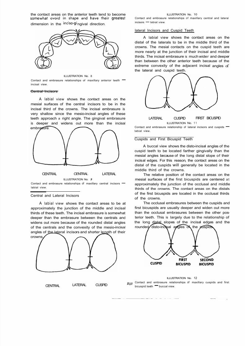
8/11/2019 An Atlas of Cast Gold Procedures
http://slidepdf.com/reader/full/an-atlas-of-cast-gold-procedures 254/270
the contact areas on the anterior teeth tend to becomesomewhat
ovoid in
shape
and
have their greatest Contact and embrasure relationships o f maxillary central and latera
ILLUSTRATION No. 10
incisors- labial view.dimension in the inciso-gingival direction.
ILLUSTRATION No. 8
Contact and embrasure relationships of maxillary anterior teeth -
incisal view.
Central Incisors
A labial view shows the contact areas on the
mesial surfaces of the central incisors to be in the
incisal third of the crowns. The incisal embrasure is
very shallow since the mesio-incisal angles of these
teeth approach a right angle. The gingival embrasure
is deeper and widens out more than the incisal
embrasure.
CENTRAL CENTRAL LATERAL
ILLUSTRATION No. 9
Contact and embrasure relationships of maxillary central incisors
-
labial view.
Central and Lateral Incisors
A lab ia l view shows the contact areas to be at
approximately the junction of the middle and incisal
thirds of these teeth. The incisal embrasure is somewhat
deeper than the embrasure between the centrals and
widens out more because of the rounded distal angles
of the centrals and the convexity of the mesio-incisal
angles of the lateral incisors and shorter length of their
crowns.
CENTRAL LATERAL CUSPID
lateral Incisors and Cuspid Teeth
A labial view shows the contact areas on the
distal of the laterals to be in the middle third of the
crowns. The mesial contacts on the cuspid teeth are
more nearly at the junction of their incisal and middle
thirds. The incisal embrasure is much wider and deeper
than between the other anterior teeth because of theextreme convexity of the adjacent incisal angles of
the lateral and cuspid teeth.
FIRST BICUSPIDLATERAL CUSPID
ILLUSTRATION No. 1 1
Contact and embrasure relationship of lateral incisors and cuspids-labial view.
Cuspids and First Bicuspid Teeth
A buccal view shows the disto-incisal angles of the
cuspid teeth to be located farther gingivally than the
mesial angles because of the long distal slope of their
incisal edges. For this reason, the contact areas on the
distal of the cuspids will generally be located in the
middle third of the crowns.
The relative position of the contact areas on the
mesial surfaces of the first bicuspids are centered a t
approximately the junction of the occlusal and middle
thirds of the crowns. The contact areas on the distals
of the first bicuspids are located in the occlusal thirds
of the crowns.
The occlusal embrasures between the cuspids and
first bicuspids are usually deeper and widen out more
than the occlusal embrasures between the other pos
terior teeth. This is largely due to the relationship of
the long distal slopes of the incisal edges and the
rounded disto-incisal angles of the cuspids.
ILLUSTRATION No. 12
Contact and embrasure relationships of maxillary cuspids and first
bicuspid teeth-buccal view.
2 40
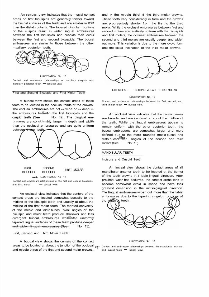
8/11/2019 An Atlas of Cast Gold Procedures
http://slidepdf.com/reader/full/an-atlas-of-cast-gold-procedures 255/270
An occ lusa l view indicates that the mesial contact
areas on first bicuspids are generally farther toward
the buccal surfaces of the teeth and are smaller in ared
than the distal contacts. The tapered cingulum portions
of the cuspids result in wider lingual embrasures
between the first bicuspids and cuspids than occur
between the first and second bicuspids. The buccal
embrasures are similar to those between the other
maxillary posterior teeth.
ILLUSTRATION No. 1 3
Contact and embrasure relationships of maxillary cuspids and
maxillary posterior teeth - occlusal view.
First and Second Bicuspid and First Molar Teeth
A buccal view shows the contact areas of these
teeth to be located in the occlusal thirds of the crowns.
The occlusal embrasures are not as wide or as deep as
the embrasures between the first bicuspids and the
cuspid teeth (See IIIus. No. 12). The gingival em-
brasures are considerably larger in depth and width
than the occlusal embrasures and are quite uniform
between these teeth.
FIRST MOLARFIRST SECOND
BICUSPID BICUSPID
ILLUSTRATION No. 14
Contact and embrasure relationships of the first and second bicuspids
and first molarteeth - buccal view.
An occlusal view indicates that the centers of the
contact areas are located somewhat buccally to the
midline of the bicuspid teeth and usually at about the
midline of the first molar teeth. The marked convexity
of the mesio and disto-buccal axial angles of the
bicuspid and molar teeth produce shallower and less
divergent buccal embrasures while the uniformly
tapered lingual surfaces of these teeth produce deeper
and wider lingual embrasures (See IIIus.
No. 13).
First, Second and Third Molar Teeth
A buccal view shows the centers of the contact
areas to be located at about the junction of the occlusal
and middle thirds of the first and second molar crowns,
and in the middle third of the third molar crowns.
These teeth vary considerably in form and the crowns
are progressively shorter from the first to the third
molar. While the occlusal embrasures between first and
second molars are relatively uniform with the bicuspids
and first molars, the occlusal embrasures between the
second and third molars are usually deeper and widen
out more. This variation is due to the more ovoid form
and the distal inclination of the third molar crowns.
FIRST MOLAR SECOND MOLAR THIRD MOLAR
ILLUSTRATION No. 15
Contact and embrasure relationships between the first, second, and
third molar teeth
-
buccal view.
An occlusal view indicates that the contact areas
are broader and are centered at about the midline of
the teeth. While the lingual embrasures appear to
remain uniform with the other posterior teeth, the
buccal embrasures are somewhat larger and more
defined due to the more rounded mesio-buccal and
disto-buccal axial angles of the second and third
molars (See IIIus. No. 13).
MANDIBULAR TEETH
Incisors and Cuspid Teeth
An incisal view shows the contact areas of a l l
mandibular anterior teeth to be located at the center
of the tooth crowns in a labio-lingual direction. After
proximal wear has occurred, the contact areas tend to
become somewhat ovoid in shape and have their
greatest dimension in the inciso-gingival direction.
The l ingual embrasures widen out more than the labial
embrasures due to the tapering cingulum portions of
tho anterior teeth.
ILLUSTRATION No. 16
Contact and embrasure relationships between the mandibular incisors
and cuspid teeth - incisal view.
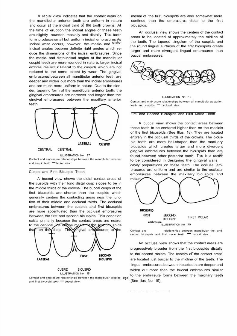
8/11/2019 An Atlas of Cast Gold Procedures
http://slidepdf.com/reader/full/an-atlas-of-cast-gold-procedures 256/270
A labial vi ew indicates that the contact areas on mesial of the f irst bicuspids are also somewhat more
the mandibular anterior teeth are uniform in nature confined than the embrasures distal to the firs
and occur a t the incisal third of the tooth crowns. At bicuspids.
the time of eruption the incisal angles of these teeth
are slightly rounded mesially and distally. This tooth
form produces small but uniform incisal embrasures. As
incisal wear occurs, however, the mesio- and disto-
incisal angles become definite right angles which re-
duce the dimensions of the incisal embrasures. Since
the mesio- and disto-incisal angles of the mandibular
An occlusal view shows the centers of the contac
areas to be located at approximately the midline o
the teeth. The tapered cingulum of the cuspids and
the round lingual surfaces of the first bicuspids create
larger and more divergent lingual embrasures than
buccal embrasures.
cuspid teeth are more rounded in nature, larger incisal
embrasures occur lateral to the cuspids which are not
reduced to the same extent by wear. The gingival
embrasures between all mandibular anterior teeth are
deeper and widen out more than the incisal embrasures
and are much more uniform in nature. Due to the slen-
der, tapering form of the mandibular anterior tooth, the
gingival embrasures are narrower and longer than the
gingival embrasures between the maxillary anterior
teeth.
ILLUSTRATION No. 19
Contact and embrasure relationships between all mandibular posterio
teeth and cuspids - occlusal view.
CENTRAL CENTRAL, LATERAL CUSPID
ILLUSTRATION No. 17
Contact and embrasure relationships between the mandibular incisors
and cuspid teeth- labial view.
Cuspid and First Bicuspid Teeth
A buccal view shows the distal contact areas of
the cuspids with their long distal cusp slopes to be in
the middle thirds of the crowns. The buccal cusps of the
first bicuspids are shorter than the cuspids which
generally centers the contacting areas near the junc-
tion of their middle and occlusal thirds. The occlusal
embrasures between the cuspids and first bicuspids
are more accentuated than the occlusal embrasures
between the first and second bicuspids. This condition
exists primarily because the contact areas are nearer
to the cervical line on the mesial of the first bicuspids
than on the distal. The gingival embrasures to the
LATERAL CUSPID BICUSPID BlCUSPlD
ILLUSTRATION No. 18
Contact and embrasure relationships between the mandibular cuspids
and first bicuspid teeth-buccal view.
First and Second Bicuspids and First Molar Teeth
A buccal view shows the contact areas betwee
these teeth to be centered higher than on the mesials
of the first bicuspids (See Illus. 18). They are located
entirely in the occlusal thirds of the crowns. The bicus
pid teeth are more bell-shaped than the maxillary
bicuspids which creates larger and more divergen
gingival embrasures between the bicuspids than are
found between other posterior teeth. This is a facto
to be considered in designing the gingival walls O
cavity preparations on these teeth. The occlusal em
brasures are uniform and are similar to the occlusa
embrasures between the maxillary bicuspids and
molars.
FIRST MOLARFIRST SECOND
BlCUSPlD BICUSPID
ILLUSTRATION No. 20
Contact andembrasure
relotionships between mandibular first and
second bicuspids and first molar teeth-
buccal view.
An occlusal view shows that the contact areas are
progressively broader from the first bicuspids distally
to the second molars. The centers of the contact areas
are located just buccal to the midline of the teeth. The
lingual embrasures between these teeth are deeper and
widen out more than the buccal embrasures simila
to the embrasure forms between the maxillary teeth
(See Illus. No. 19).

8/11/2019 An Atlas of Cast Gold Procedures
http://slidepdf.com/reader/full/an-atlas-of-cast-gold-procedures 257/270
First, Second and Third Molar Teeth mated to be about one-fourth the measurement from
the tip of a buccal cusp to the tip of a corresponding
lingual cusp. The bucco-lingual dimension of the contact
areas between the molar teeth of middle-aged persons
is estimated to be approximately one-third the measure-
ment from the tip of a buccal cusp to the tip of a
corresponding lingual cusp (See Illus. No. 13 and
No. 19).
The occluso=gingival dimensions
of the contact
A buccal view shows the contact relationships to
be quite uniform between these teeth. The contact
areas are centered near the junction of the middle and
occlusal thirds of the tooth crowns. While the gingival
embrasures are larger and more defined
than
the
occlusal embrasures, they are not as wide nor defined
as the embrasures between the bicuspid teeth.
SECOND FIRST MOLAR SKOND MOLAR THIRD MOLAR
BICUSPID
ILLUSTRATION No. 21
Contact and embrasure relationships between mandibularf int ,
second and third molar teeth - buccalview.
An occlusal view snows the contact areas TO De
centered near to the midline of the crowns with only
a slight tendency to be located toward the buccal. The
buccal and lingual embrasures between these teeth
appear to be progressively larger from the first molars
to the third molars. These slight changes in embrasure
form are created by the rounded outline of the distal
axial angles of the first molars and the rounded mesial
and distal axial angles of the second and third molars.
It must be emphasized that the design of the contact
areas and embrasures between the teeth are influenced
by the size and form of the individual tooth crowns
(SeeIllus.
No. 19).
DIMENSIONAL GUIDES FOR AREAS OF
CONTACT BETWEEN POSTERIOR TEETH
As previously described, the "marble-like" point
contacts of newly erupted permanent teeth soon wear
into actual "areas" of contact with dimensions in both
bucco-lingual and occluso-gingival directions.
The smallest posterior contacts occur on the mesial
surfaces of the maxill ary and mandibu lar first bicuspids.
In general, the areas of contact between the posterior
teeth become progressively larger from the first bicus-
pids distally through the molars. The exceptions to this
condition are the somewhat reduced contact areas be-
tween the second and third molars which i s due to the
conical shape and the smaller size of the third molar
crowns.
The contact areas of the posterior teeth are
essentially ovoid in shape with their greatest dimension
in the bucco-lingual direction.
The bucco-lingual dimension of the contact areas
between the bicuspid teeth of middle-aged persons
with the usual amount of interproximal wear is esti-
~
areas between the posterior teeth are estimated to befrom one-third to one-half that of the bucco-lingual
dimensions.
While these measurements are estimates, they can
be used as effective guides for establishing contact
area relationships between the posterior teeth.
OCCLUSAL RELATIONSHIPS OF THE WORKING
SURFACES OF THE TEETH DURING FUNCTION
The working surfaces of the teeth present curved
lines. When flat inclines occur on incisal or occlusal
surfaces, they are the product of wear or injury. When
unworn teeth of the opposing arches come together in
function, their curved surfaces meet at "points" or very
small "circumscribed areas" of contact. As the teeth
move against each other, their curved surfaces act as
cutting blades. The depths of the developmental and
supplemental grooves become escapeways for food
and together with the triangular ridges on the occlusal
surfaces make it possible to penetrate or reduce fibrous
food substances much more readily. When flat occlusal
surfaces are created through wear, the efficiency of
mastication is reduced in relation to the extent of the
wear. In the restoration of the occlusal surfaces of
teeth it should be an objective of the operator toreproduce ideal functional form in so far as the existing
conditions of the surfaces of the opposing teeth permit.
To accomplish this it is sometimes desirable to alter the
working surfaces of the opposing tooth or teeth by
reshaping or restoring them.
The maxillary and mandibular arches form sym-
metrical curves. The curvature of the maxillary arch
i s somewhat greater than that of the mandibular
arch. Because of this relationship of the arches relative
degrees of overjet and overbite exist between the
maxillary and mandibular teeth. The overjet of the
buccal cusps of the maxillary teeth and the lingual
cusps of the mandibular teeth prevents impingementof the lips, cheeks and tongue during the closing action
of the jaws and permits occlusal apposition of the
teeth during a greater latitude of excursive movements
of the mandible.
In hinge occlusion position, the working surfaces
of mandibular teeth come into contact with certain
corresponding points or circumscribed areas on the
surfaces of the maxillary teeth. Since the sizes of the
dental arches do not conform, identical surfaces of the
opposing teeth do not come into contact during terminal

8/11/2019 An Atlas of Cast Gold Procedures
http://slidepdf.com/reader/full/an-atlas-of-cast-gold-procedures 258/270
hinge occlusion. In normal arches, with the exception
of the mandibular centrals and maxillary third molars,
the teeth of one arch make occlusal contact with the
surfaces of two teeth in the opposing arch. This is a
factor in stabilizing the teeth in the arches and
distributing work loads during mastication and occlusal
contact.
Cusp-fossa and cusp-ridge relationships of the
teeth in hinge occlusion position and during functional
movements of the mandible are described and illus-trated. The conditions presented occur within a
standard deviation for occlusal relationships between
the maxillary and mandibular teeth. The variations
described in the following sections will serve as a
guide for incorporating the biologic and physiologic
requirements of tooth form and function when fabri-
cating wax patterns on the working models.
CUSP-FOSSA AND CUSP-RIDGE INTER-OCCLUSAL
RELATIONSHIPS IN HINGE OCCLUSION POSITION
Mandibular Teeth
lncisors-
The incisors contact the lingual surfaces of the
maxillary anterior teeth in the incisal third area.
Cuspid-
The mesio-incisal slope contacts the disto-lingual
marginal ridge of the maxillary lateral in the incisal
third area. The disto-incisal slope contacts the mesio-
lingual marginal ridge of the maxillary cuspid in the
incisal third area.
First Bicuspid-
The buccal cusp contacts the mesial marginal ridge
of the maxillary first bicuspid slightly buccally to themidline. The mesial slope of the buccal cusp contacts
the disto-lingual marginal ridge of the maxillary cuspid
in the incisal third area.
Second Bicuspid-
ridge of the maxillary first molar and the mesial mar -
ginal ridge of the maxillary second molar at about the
midline of the teeth.
The disto-buccal cusp rests in the central fossa of
the maxillary second molar.
The distal cusp when present rests in the distal
fossa of the maxillary second molar mesially to the
distal pit.
Third Molar -
The mesio-buccal cusp usually rests on the mesial
marginal ridge of the maxillary third molar.
The disto-buccal cusp usually rests in the central
fossa of the maxillary third molar distally to the
central pit.
The distal cusp when present is in opposition to
the mesial portion of the distal fossa of the maxillary
third molar.
The greatest degree of variation in tooth
relationships in the arches exists between the third
molars.
Lingual Cusps-
In general the buccal triangular ridges of thelingual cusps of most mandibular teeth make limited
contact with the lingual cusp ridges of the lingual cusps
of the maxillary teeth. This relationship will exist unless
excessive wear alters the occlusal surfaces. of the
maxillary and mandibular teeth to produce more
extensive inter -cuspal contact.
CUSP-FOSSAE AND CUSP-RIDGE INTER-OCCLUSAL
RELATIONSHIPS IN HINGE OCCLUSION POSITION
Maxillary Teeth
lncisors-
The l ingual surfaces are contacted in the incisal
third area by the labio-incisal edges of mandibular
anterior teeth.
Cuspid-
The buccal cusp contacts the mesial marginal ridge
of the maxillary second bicuspid at approximately the
midline of the tooth.
First Molar -
The crest of the cusp is positioned labially to the
embrasure between the mandibular cuspid and first
bicuspid. These two teeth contact the lingual surface of
the maxillary cuspid in its incisal third area. The man-
dibular cuspid contacts the mesio-lingual marginal r idge
of the maxillary cuspid. The mandibular first bicuspid
contacts the disto-lingual marginal ridge of the maxil-
lary cuspid.
First Bicuspid-
The mesio-buccal cusp contacts the distal marginal
ridge of the maxillary second bicuspid and the mesial
marginal ridge of the maxillary first molar buccally to
the midline of the teeth.The disto-buccal cusp rests in the central fossa of
the maxillary first molar.
The distal cusp is in apposition to the mesial
portion of the distal fossa of the maxillary first molar.
Its mesial cusp ridge may contact the distal surface of
the oblique ridge of the maxillary first molar at about
the position of the central groove.
Second Molar -
The mesio-buccal cusp contacts the distal marginal
The buccal cusp is located buccally to the
embrasure between the first and second mandibular
bicuspids.The lingual cusp has a marked mesial inclination
and rests in the distal fossa of the mandibular first
bicuspid.
Second Bicuspid-
The buccal cusp is located bucally to the embrasure
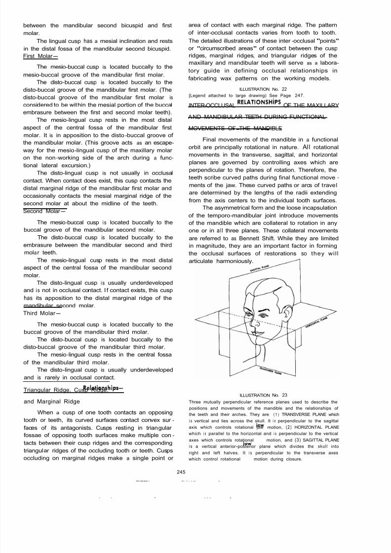
8/11/2019 An Atlas of Cast Gold Procedures
http://slidepdf.com/reader/full/an-atlas-of-cast-gold-procedures 259/270
between the mandibular second bicuspid and first
molar.
The lingual cusp has a mesial inclination and rests
in the distal fossa of the mandibular second bicuspid.
First Molar -
The mesio-buccal cusp is located buccally to the
mesio-buccal groove of the mandibular first molar.
The disto-buccal cusp is located buccally to the
disto-buccal groove of the mandibular first molar. (The
disto-buccal groove of the mandibular first molar isconsidered to be within the mesial portion of the buccal
embrasure between the first and second molar teeth).
The mesio-lingual cusp rests in the most distal
aspect of the central fossa of the mandibular first
molar. It is in apposition to the disto-buccal groove of
the mandibular molar. (This groove acts as an escape-
way for the mesio-lingual cusp of the maxillary molar
on the non-working side of the arch during a func-
tional lateral excursion.)
The disto-lingual cusp is not usually in occlusal
contact. When contact does exist, this cusp contacts the
distal marginal ridge of the mandibular first molar and
occasionally contacts the mesial marginal ridge of the
second molar at about the midline of the teeth.
Second Molar -
The mesio-buccal cusp i s located buccally to the
buccal groove of the mandibular second molar.
The disto-buccal cusp is located buccally to the
embrasure between the mandibular second and third
mola r teeth.
The mesio-lingual cusp rests in the most distal
aspect of the central fossa of the mandibular second
molar.
The disto-lingual cusp i s usually underdeveloped
and i s not in occlusal contact. I f contact exists, this cusphas its apposition to the distal marginal ridge of the
mandibular second molar.
Third Molar -
The mesio-buccal cusp is located buccally to the
The disto-buccal cusp is located buccally to the
The mesio-lingual cusp rests in the central fossa
The disto-lingual cusp is usually underdeveloped
buccal groove of the mandibular third molar.
disto-buccal groove of the mandibular third molar.
of the mandibular third molar.
and is rarely in occlusal contact.
Triangular Ridge, Cusp Ridge,
and Marginal Ridge Relationships-
When a cusp of one tooth contacts an opposing
tooth or teeth, its curved surfaces contact convex sur -
faces of its antagonists. Cusps resting in triangular
fossae of opposing tooth surfaces make multiple con-
tacts between their cusp ridges and the corresponding
triangular ridges of the occluding tooth or teeth. Cusps
occluding on marginal ridges make a single point or
245
area of contact with each marginal ridge. The pattern
of inter -occlusal contacts varies from tooth to tooth.
The detailed illustrations of these inter -occlusal "points"
or "circumscribed areas" of contact between the cusp
ridges, marginal ridges, and triangular ridges of the
maxillary and mandibular teeth will serve as a labora-
tory guide in defining occlusal relationships in
fabricating wax patterns on the working models.
ILLUSTRATION No. 22
INTER-OCCLUSAL RELATlONSHiPS OF THE MAXILLARY
AND MANDIBULAR TEETH DURING FUNCTIONAL
MOVEMENTS OF THE MANDIBLE
[Legend attached to large drawing) See Page 247.
~~ ~~
Final movements of the mandible in a functional
orbit are principally rotational in nature. Al l rotational
movements in the transverse, sagittal, and horizontal
planes are governed by controlling axes which are
perpendicular to the planes of rotation. Therefore, the
teeth scribe curved paths during final functional move-
ments of the jaw. These curved paths or arcs of travel
are determined by the lengths of the radii extendingfrom the axis centers to the individual tooth surfaces.
The asymmetrical form and the loose incapsulation
of the temporo-mandibular joint introduce movements
of the mandible which are collateral to rotation in any
one or in al l three planes. These collateral movements
are referred to as Bennett Shift. While they are limited
in magnitude, they are an important factor in forming
the occlusal surfaces of restorations so they wil l
articulate harmoniously.
ILLUSTRATION No. 23
Three mutually perpendicular reference planes used to describe the
positions and movements of the mandible and the relationships of
the teeth and their arches. They are: ( 1 ) TRANSVERSE PLANE which
i s vertical and lies across the skull. It i s perpendicular to the sagittal
axis which controls rotational jaw motion, (2) HORIZONTAL PLANE
which i s parallel to the horizontal and i s perpendicular to the vertical
axes which controls rotational jaw motion, and (3) SAGITTAL PLANE
i s a vertical anterior -posterior plane which divides the skull into
right and left halves. It i s perpendicular to the transverse axes
which control rotational i a w motion during closure.
. . . . . . . . . ~ .

8/11/2019 An Atlas of Cast Gold Procedures
http://slidepdf.com/reader/full/an-atlas-of-cast-gold-procedures 260/270
U
S
ILLUSTRATION No. 24
A schematic il lu st rat io n o f the three non-intersecting but mutually
perpendicular axes which pass through the Temporo -mandibular
Joint. They are: 1 ) the TRANSVERSE AXES which control rotational
i a w motion in the sagittal plane closure, (2) the VERTICAL AXES
which control lateral jaw rotation in the ho rizontal plane, and (3) the
SAGITTAL AXES which control the rocking motion o f the jaw in the
transverse plane.
Monsonl has described compensating curvatures
of the arches in both the sagittal and transverse planes.
These compensating curvatures and the arrangement of
the teeth in their arches make it possible for the teeth
to achieve functional articulation during movements
of the mandible. The curvatures of the arches in the
sagittal plane (curve of Spee) and the mesio-distal ILLUSTRATION No. 25
inclinations of the cuspids and posterior teeth, as well
as the angulation of their roots, establish the long axis
of each individual tooth in harmony with the forces of
occlusion. The curve of Spee and the compensating
inclinations of the individual teeth and the curvatures
of their roots are important factors in stabiliizing the
Compensating curvatures of the teeth and their arches.
A. Comp ensat ing curvatures of the individual teeth and #heir roots
B. Compensating curvatures of the dental arches in the sagitta
plane (Curve o f Spee).
Compensating curvatures o f the teeth and their arches in the
vertical plane.
C.
arches.The medial inclination of the mandibular posterio
teeth establishes the buccal cusps on a higher plane
than the lingual cusps. This compensating curvature o
the mandibular posterior teeth in the transverse plane
together with the overbite relationship of the bucca
cusps of the maxillary teeth permit an occlusal balance
between the buccal cusps of the maxillary and man
dibular teeth in functional lateral excursions. Occlusa
balance is attained when segments of teeth in one arch
come into simultaneous contact with tee th of the
opposing arch. At the same time the compensating
factors of occlusal curvatures and overbite relationshiptend to disarticulate the lingual cusps of the teeth on
the working side of the arches. This arrangement re
duces the possibility of traumatic interferences. When
waxing patterns on the working model, care must be
taken against creating long l ingua l cusps on the
mandibular posterior teeth. This would reduce the
compensating curvature in the transverse plane and
cou
Id introduce interfering re l a t ionships during
functional movements of the jaw.
I ] George S. Monron,
" Applied Mechanics to the Theory of Mandibular Movements.
DENTAL COSMOS, Vol.
LXXIV (Nov.. 1932.

8/11/2019 An Atlas of Cast Gold Procedures
http://slidepdf.com/reader/full/an-atlas-of-cast-gold-procedures 261/270

8/11/2019 An Atlas of Cast Gold Procedures
http://slidepdf.com/reader/full/an-atlas-of-cast-gold-procedures 262/270
Ncu-w(HII*G yo
WORKING SlD l
ILLUSTRATION No. 26
A favorable l ine of force which falls wi thi n an area circumscribed i s
created by occlusal contact of the buccal cusps of the maxillary and
mandibular teeth on the working side of the arches by the attach -
ment apparatus. If long lingual cusps are created in the restoration
of the mandibular posterior teeth, occlusal interferences and an
undesirable line of force may be established as i s indicated by the
dotted line. In a normal occlusion the teeth on the non-working side
of the arches do not come into contact during a chewing stroke.
LATERAL MOVEMENT
AT FRONT LEFT SIDECHEWING.
60
LATERAL MOVEMENT
RIGHT SIDECHEWING.
67'
AT FRONT
In an average occlusion it is also a function of the
compensating curvatures of the teeth and their arches,
along with the overbite of the buccal cusps of the
maxillary posterior teeth to completely disarticulate
the teeth on th-. non-working side. For purposes of
description, the term "working side" applies to the
side of the arch corresponding to the direction of the
lateral excursion. That is, the right side of the arch
is the "working side" during a right-lateral excursion.
The "non-working side" would be the opposite or left
side of the arch (See Illus. 26).
Contrary to the full denture concept of articulation
where "cross-mouth" balance i s necessary to stabilize
the denture bases, the general consensus is that there
should be no contact of the teeth on the "non-working
side" of the arch in the dentulous mouth during a
lateral functional excursion. Such contact is considered
to be traumatic in nature and is generally the result
of excessive wear of the dentition. In most instances
where "cross-mouth balance" does exist, excessive
wear of the maxillary cuspids will be observed. Oc-
clusal interferences on the "non-working side" of the
arch is a common etiologic factor in abnormal function
of the temporo-mandibular joint.
The normal arrangement of the maxillary cuspidsin the arch before wear occurs prevents occlusal contact
of the posterior teeth on the "non-working side" during
lateral functional movements.2 The so-called "cuspid
protection" principle3 has been applied successfully for
some time in the current concept of full mouth recon-
LATERAL MOVEMENT
AT FRONT LEFT SIDECHEWING.
LATERAL MOVEMENT
RIGHT SIDE
~
AT FRONT
12)
Angelo
D'Amico,
"Functional Occlusion of the Noturol Teeth of Man,
JOURNAL OF PROS. DENT., Vol. II, [Sept.-Oct., 1961)
3 ) Harvey Stollard and Charles E. Stuart,
"Concepts of Occlusion,"
struction. In a "cuspid-protected" occlusion the relatio
of the lingual surfaces of the cuspid teeth do no
entirely harmonize with the lingual inclines of th
buccal cusps of the posterior teeth. The cuspid relation
ship permits balancing contact on the working side o
the arch for a limited excursion of 1 or 2 mm. afte
which the steeper inclines of the cuspid teeth disengag
the posterior teeth entirely. The architecture of the roo
and bony support of the cuspid teeth together wit
the propreoceptive response to traumatic stimuli pro
vide the protective mechanism against injury. In
"cuspid-protected" occlusion the teeth on the "non
working side" of the arch are completely disengage
during a lateral excursion of the jaw.
INTERCUSP RELATIONSHIPS OF THE TEETH
DURING FUNCTIONAL MOVEMENTS
OF THE MANDIBLE
"Working Balance" is achieved as the arche
approach hinge occlusion position from a lateral ex
cursive position. The buccal cusps of the maxillar
teeth engage the buccal cusps of the mandibular teet
on the working side. The mandible is capable o
making very wide ranges of motion. During th
"functional orbit" of the mandible in a chewing stroke
however, the teeth come together in only very sho
arcs of contact. Balancing contact occurs only as th
teeth approach a terminal hinge occlusion position
The arcs of travel during which the teeth may com
into contact during a chewing stroke are very limited
perhaps 2 mm. or less. Whether the teeth actual
contact or not during their functional orbit depend
upon the resistance of the food substance between th
teeth.
ENVELOPE OF MOTION. The functionali aw
pattern described
Boswell*
can be used as a guide for establishing cusp inclinatio
when articulating posterior teeth. Tracings of functionaljaw
patte
boundaries show the flattest closing angle of thejaw
to be 50
during chewing and steepest to be6 8 .
Within these boundarie
well articulated teeth never touch until they reach their final termin
hinge occlusion position.
Boswell , Jess V.:Pract icol Occlusion in Relation to Complete Dentures,
Pros. D. 1:307 321 (May] 1951.

8/11/2019 An Atlas of Cast Gold Procedures
http://slidepdf.com/reader/full/an-atlas-of-cast-gold-procedures 263/270
The intercusp relationships of the maxillary and
mandibular posterior teeth in hinge occlusion position
have already been described. In an intercusp relation-
ship during the final phase of functional closure the
lingual surfaces of the buccal cusps of the maxillary
teeth on the "working side" engage the buccal sur -
faces of the buccal cusps of the mandibular teeth.
The mandibular teeth move in arcs about the vertical,
sagittal, and horizontal axes. These arcs of travel are
determined by the radii extending from the con-trolling axes within the working joint to the respective
surfaces of each tooth. Naturally, the cuspid teeth move
on larger arcs than the third molars which move on
very short arcs with their shorter radii to the axis centers.
TRANSVERSE AXIS,
n SAGlllAL AXIS,
C
ILLUSTRATION No. 28
The direction and the degree o f curvature of the arcs in which the
individual teeth travel as rotational movements take places around
the three controlling axes are illustrated.
A. Movement around the transverse axes.
B. Movement around the vertical axes.
C. Movement around the sagittal axes.
A
As the teeth move from lateral relation to their
hinge occlusion position the cuspid and buccal cusps
of the posterior maxillary teeth pass through the
respective embrasures and buccal grooves of the
mandibular molar teeth which they approximate.
Illustration Number 22 is designed to demonstrate the
intercusp relationships of the maxillary and mandibular
teeth as they approach hinge occlusion position from a
lateral excursive position. Move the arches in the illus-
tration into a left lateral relationship as indicated, to
study intercusp relationships. As previously stated, in
an average occlusion the teeth on the "non-working
side" and the lingual cusps of the teeth on the
"working side" are disarticulated and make no occlusal
contact in a lateral excursion.
The physiologic considerations of tooth form and
the concepts of inter -occlusal relationships of the work-
ing surfaces of the teeth in function described in this
Chapter, are as important to the restoration of a single
tooth as to an extensive full mouth rehabilitation.
If finished castings are to embody al l of the
biological and physiological requirements of tooth form
and function, then axial contours, embrasure and
marginal ridge relationships, proper shape, size and
position of contact areas, and functional occlusal
anatomy must first be developed in the waxing
procedures on the working model.B
49

8/11/2019 An Atlas of Cast Gold Procedures
http://slidepdf.com/reader/full/an-atlas-of-cast-gold-procedures 264/270
THE ORIGINAL BASIC FIVE-STEP ADDITIVE TECHNIC FOR A FUNCTIONAL WAX-UP - DEVELOPED BY EVERITT V. PAY
Armamenta riu m- left, a Wards' No. 1 waxing instrument
used for major part of wax -up. Right, a converted No. 23
sickle explorer - flat tened on two sides, non-tapering and
flattened on the end to hold a bead of melted wax. It is used
for all detailed waxing procedures.
Moving the casts on the articulator into a protrusive lateral
position (ti ps of max illa ry buccal cusps to tips of mandibularbuccal cusps) provides a general guide for determining the
relative position and the maximum possible lengths of the
buccal cusps of the posterior teeth . . .
The mesio-distal distances between the bucca l cusps of the
teeth are progressively less from the cuspid distally through
the third molar.
Step I-Build-up of Cones
The tips of the wox cones establish the location and heigh
of the cusps of the tooth in relation to the occlusal curves.
. . , The position of the cusp tips of the posterior teeth may be
located in a bucco-lingual relationship by applying the Rule oThirds. ( 1 ) The First Third i s a measurement from the heigh
of the most convex surface of the tooth (buccal of mandibular
and lingual of maxillaries) to the tip of the nearest cusp
(2) The Second Third is measured from the tip of the cusp to
the central groove of the occlusal surface. (3) The Last Thir
i s measured from the central groove to the tip of the opposite
cusp.
Relationship of the lingual cusps of the maxillary teeth to th
buccal cusps. Note mesial version of the lingual cusps of th
bicuspids. Mesial lingual cusps of molars can be viewe
between the mesial and distal buccal cusps.
950

8/11/2019 An Atlas of Cast Gold Procedures
http://slidepdf.com/reader/full/an-atlas-of-cast-gold-procedures 265/270
They are the maior fossa1 cutting blades of the posterior teeth.
Step IV- Adding the Marginal Ridges.
This step completes all of the working elements of the occlusal
surfaces of the teeth.
Step - Adding the Mesial and Distal Cusp Ridges.
The casts on the articulator may be moved into a lateral
relationship to determine the degree of inclination necessary
to permit free passage of the cusp in lateral excursions.
Step V
The modified No. 23 sickle explorer permits the addition of
minute quantities of wax to build up fine sharp ridges and to
produce fine grooves.
Completed functional wax-up.
251
Step I-Buildup of buccal and lingual conel.

8/11/2019 An Atlas of Cast Gold Procedures
http://slidepdf.com/reader/full/an-atlas-of-cast-gold-procedures 266/270
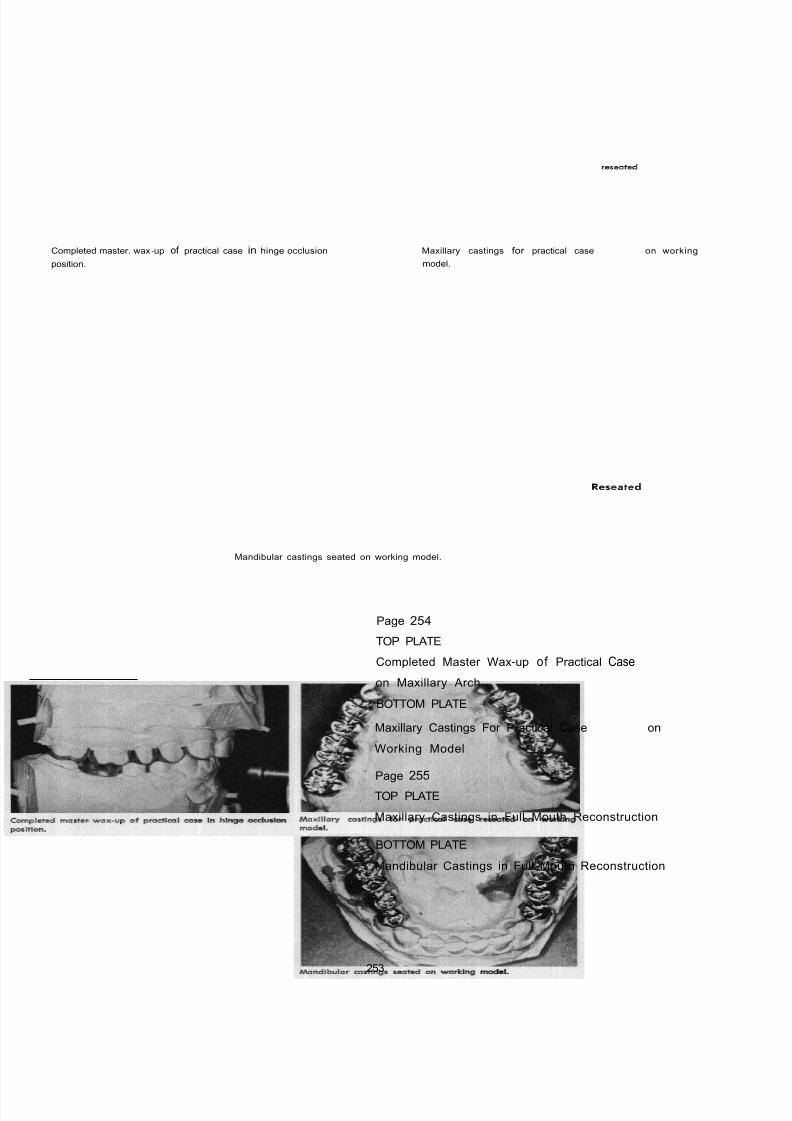
8/11/2019 An Atlas of Cast Gold Procedures
http://slidepdf.com/reader/full/an-atlas-of-cast-gold-procedures 267/270
Completed master. wax -up of practical case in hinge occlusion
position.
Maxillary castings for practical case reseated on working
model.
Mandibular castings seated on working model.
Page 254
TOP PLATE
Completed Master Wax-up of Practical Case
on Maxillary Arch
BOTTOM PLATE
Maxillary Castings For Practical Case Reseated on
Working Model
Page 255
TOP PLATE
Maxillary Castings in Full Mouth Reconstruction
BOTTOM PLATE
Mandibular Castings in Full Mouth Reconstruction
253

8/11/2019 An Atlas of Cast Gold Procedures
http://slidepdf.com/reader/full/an-atlas-of-cast-gold-procedures 268/270
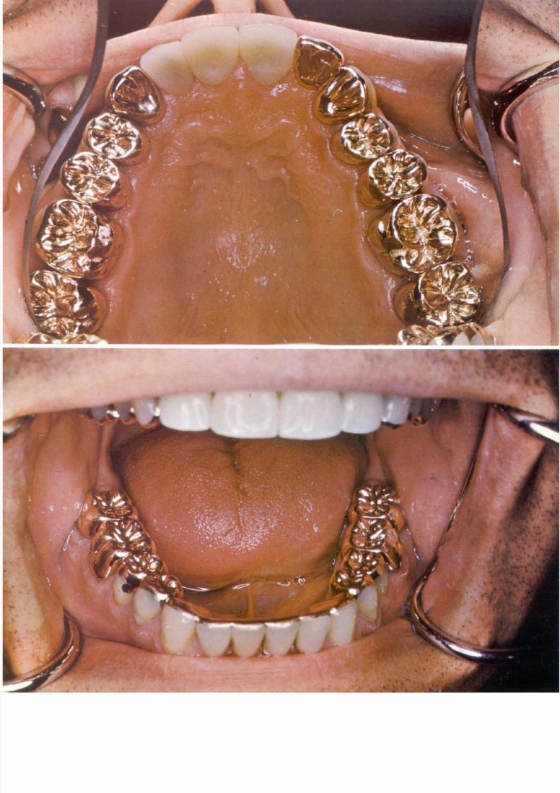
8/11/2019 An Atlas of Cast Gold Procedures
http://slidepdf.com/reader/full/an-atlas-of-cast-gold-procedures 269/270

8/11/2019 An Atlas of Cast Gold Procedures
http://slidepdf.com/reader/full/an-atlas-of-cast-gold-procedures 270/270