an implementation of two-stage hybrid state estimation...
TRANSCRIPT
AN IMPLEMENTATION OF TWO-STAGE HYBRID STATEESTIMATION WITH LIMITED NUMBER OF PMU
Richard Baltensperger+, Alain Loosli+, Hubert Sauvain+, Marija Zima−, Goran Andersson−, Reynaldo Nuqui*+College of Engineering and Architecture Fribourg, University of Applied Sciences HES-SO,
Perolles 80, CH-1705 Fribourg, Switzerland, email:[email protected]−Power Systems Laboratory, ETH Zurich (Swiss Federal Institute of Technology),Physikstrasse 3, CH-8092 Zurich, Switzerland, Web: http://www.eeh.ee.ethz.ch/psl
*ABB US Corporate Research Center, 940 Main Campus Drive, Raleigh, NC 27606, USA
Keywords: Power system state estimation, Wide area moni-toring, Phasor measurement units, Measurement errors.
AbstractState estimation is an important tool for power system su-pervision and control and the related applications. Basedon the redundant measurements taken in the network, stateestimation provides the most likely state of the power system.Conventional measurements were collected by the SCADAsystem and the measurement chain did not allow measurementsynchronization. A disadvantage is that due to the communi-cations delay measurements inherit an additional error andsimultaneously voltage angle measurements are not available.With the advent of phasor measurement units (PMU’s), syn-chronized phasor measurements are possible. It allows toenhance the performance of state estimators. Expecting thegradual penetration of PMUs this paper discusses possiblehybrid SE methods, integrating partial PMU measurementsinto the classical SE systems.
1 IntroductionThe secure operation of power system must be ensured by theControl Center operators, and a primary need of the operatorsis reliable information. Establishment of Supervisory ControlAnd Data Acquisition (SCADA) systems was an importantachievement. However, data obtained from SCADA is notalways correct containing e.g. measurement or circuit breakerstatus errors. Moreover, not all the measurements are availablein the Control Center.
These concerns were first recognized by Fred Schweppe,who proposed and investigated State Estimation (SE) methods[13] likely state of power system from possibly limited rawmeasurement data.
Nowadays, state estimation is an important and a widely usedcontrol center tool [9] , [2], [6]. It forms the basis for a numberof applications, such as:
• System observation;• Security assessment;• Optimal power flow;• Transmission system usage billing.
The performance and reliability of SE thus have economicimplications [3] and are getting a great attention.
The next technological breakthrough has came with the devel-opment of phasor measurement units (PMUs) by Phadke [10]and the revolutionary formulation of the linear state estimationwith PMU measurements. Due to the large dimensionality andthus the long time constants for the exchange of the powersystems equipment, the question of gradual implementationof the phasor measurements units becomes essential.
State estimation accuracy and reliability could benefit alsofrom the partial availability of PMUs [4]. The control centeralgorithms has to be modified correspondingly. Two groupsof methods can be distinguished:
• direct implementation in SE;• non-invasive implementation, decoupling PMU measure-
ments from classical SE.
Direct methods would have an advantage of improving theclassical state estimator overall performance, first of all,robustness. While the second group of methods contributesmostly to accuracy and bad data detection capability. It doesnot require to change the main SCADA software package andcan be easily implemented [8].
This paper studies non-invasive PMU implementation meth-ods, evaluates the advantages brought by those on theoreticalexamples supported by the simulations, as well as discussesan implementation and tests of the proposed algorithm on ananalogue power system model [14], [15].
2 Theoretical Background
2.1 Classical State Estimation procedure
Let us first review the classical state estimation procedure.Majority of the state estimators (SE) nowadays rely on thebus-branch transmission system model obtained by the topol-ogy processor from the detailed model including switchesand those states. We assume model parameters includingphase shifting transformers and the high voltage dc line tobe known. The model and the measured values are passed tothe state estimator that involves the mapping of the states xto measurements z with measurement errors e:
zi − hi(x) = e
with x = (θ1θ2 . . . θnU1 . . . Un)T , (1)
where h(x), known as the measurement function, relates thesystem state vector x containing voltage angles and magni-tudes to the measured quantities - voltage magnitudes Vi, buspower injections Pi, Qi and branch power flows Pij , Qij .
The measurement errors are assumed stochastic with a Gaus-sian probability distribution, zero mathematical expectationvalues and mutual independence. Therefore, equation (1) canbe solved giving the most likely values of the state variablesbased on the given measurements.
Since the measurement error expectation values have beenassumed to be zero, the most likely estimation in this casecorresponds to the states minimizing the following objectivefunction [13], [2]:
J =m∑
i=1
Wii [zi − hi(x)]2 . (2)
The weights Wii are inversely proportional to the measure-ment error variance Wii = 1/σ2
i .
The minimum of J can be determined using the first orderoptimality conditions g(x) = ∂J(x)
∂x = 0. Expanding g(x) inTaylor series around x(k) and neglecting higher order terms,we obtain:
g(x(k)) +∂g(x(k))∂x
(x− x(k)) = 0. (3)
Thus, the Gauss-Newton iterative solution scheme [5] can beemployed to find x satisfying Equation (3).
Rearrangements lead to so called Normal equations:
G(xk)∆x(k+1) = HT (x(k)) ·W · [z − h(x(k))], (4)
where
• G(x) = ∂2J(x)∂x2 = HT (x) ·W ·H(x) is the gain matrix
• ∆x(k+1) is the update of the solution at iteration k, sox(k+1) = x(k) + ∆x(k+1)
• H(x) = ∂h(x)∂x is the measurement Jacobian.
Phasormeasurements
Direct Solution and Result Output
1. Stage State Estimation
Analog measuments
2. Stage Enchanced
State EstimationVr,
Vi,
I r, I i
x <
Vr, Vi, Ir, Ii
Start
Pb, Qb, Vb, Pf,Qf
Classical SE
NO YES
Figure 1: Flow chart of the implemented SE procedure.
Solving equation (4) for ∆x(k+1) and iterating until therequired accuracy ε is reached, i.e. ∆x(k+1) < ε, one willobtain the solution of SE.
2.2 Enhanced State Estimator with Phasor MeasurementUnits
In [8] a two-stage non-invasive PMU integration scheme isproposed, as in Figure 1. The classical SE gives estimatedvoltages as a pseudo measurement in addition to PMUsmeasurements to the second stage SE. The second stageinvolves, due to the formulation in rectangular coordinates,the linear measurement model:
M = HV + ε, (5)
where M is a measurement vector, H is a measurementJacobian matrix, V = [VrVi]T is a state vector in rectangularcoordinates and ε is the measurement noise.
In the extended form Equation (5) therefore, is given by:
M =
[Vr
Vi
]se
[Vr
Vi
]pmu
[IrIi
]pmu
=
1 00 1
1 00 1
∂Ipmur
∂Vr
∂Ipmur
∂Vi
∂Ipmui
∂Vr
∂Ipmui
∂Vi
[Vr
Vi
]+
εseV r
εseV i
εpmuV r
εpmuV i
εpmuIr
εpmuIi
,
(6)where V are the voltages, I are the currents, superscripts seand pmu denote the source of the information, subscriptsr and i denote correspondingly the real and the imaginarycomponents of the parameter and 1 is the identity matrix withones at the diagonal and zeros otherwise.
The values of partial derivatives in Equation (6) can easily beobtained from the π-model of the network branch, which islinear in the complex form:
Ikm = (y + ysh)Vk − yVm, (7)
where Ik is the complex current in the branch km at node k,Vk, Vm are the voltages in the nodes k and m, y is the seriesadmittance of the branch km, ysh the shunt admittance of thebranch.
Proceeding with transformations in rectangular form and theseparation of the real and the imaginary part results in forexample ∂Ipmu
kmr
∂Vki= −(yi + ysh
i ).
Similarly to Equation (2) the weighted least square problemcan be formulated, as:
J =[M −HV
]TW[M −HV
]. (8)
The formulation of the first order optimality condition resultsin:
∂J(V )∂V
∣∣∣∣V =V
= HTWHV −HTWM = 0. (9)

and the estimates V can be obtained as result of the non-iterative computation:
HTWHV = HTWM. (10)
The covariance matrix elements should be in this case ex-pressed in rectangular components.
2.3 Implemented state estimation procedure with PMU
The state estimation scheme was implemented according tothe method proposed by Nuqui [8] with the following modifi-cations discussed below. Similarly to [8] in the first stage, themeasurements are collected and processed by classical stateestimation procedure as in [13]. The results of this first stagestate estimation, namely bus voltages together with the PMUmeasurements are forming the measurement vector for thesecond stage state estimation.
The addition proposed by the authors to this algorithm is theintroduction of supplementary current measurements on thesecond stage of state estimation. These current measurementsare computed from the first stage state estimation results andintroduced into the measurement vector of the second stagestate estimator:
M =
[Vr
Vi
]se
[...]pmu
[IrIi
]se
=
1 00 1
......
∂Iser
∂Vr
∂Iser
∂Vi∂Ise
i
∂Vr
∂Isei
∂Vi
[Vr
Vi
]+
εseV r
εseV i...εseIr
εseIi
. (11)
Such modification still allows to preserve decoupled structureof the classical SE and the PMU based one and, simultane-ously, decrease impact of possible bias in the PMU currentmeasurements. Thus, the estimation procedure is becomingmore balanced.
3 Simulations and Results3.1 Test System
The method was tested on the 4 bus model [14], [15],representing part of the swiss transmission network (Figure2). The slack node Breite represents the connection to the400 kV grid. It contains two phase shifting transformersand HVDC transmission line. System parameters are given
Line RL XL CNr [Ω] [Ω] [nF]8 9.834 12.678 3311 5.379 12.779 3312 7.855 19.304 477 7.939 19.331 476 0.292 2.796
Table 1: System parameters.
Figure 2: Single line diagram of the test system and locationof the PMU.
in table 1. The capacitance was considered in the practicalmodel in Section 4, and neglected in the software simulations.Transformation ratio of the phase shifting transformers wereset to 1.05ej5 and 1.05ej10 .
Measurement system consists of 2 synchronized voltage mea-surements, 3 synchronized currents and all the unsynchro-nized voltages and 1 flow measurement per branch. Thesemeasurement values were simulated by perturbing the valuesdetermined by the the power flow. Measurement noise [8] isnormally distributed N(0, σ) with the variance given by:
• σ|V | = 1.2%, σ|I| = 0.6%,• σangle(V ) = 1.04, σangle(I) = 1.04.
3.2 Results
For the power flow simulation a Newton-Raphson methodwas implemented [6] and converged in 3 iterations with theaccuracy of 10−5. Simulations were also verified by theNeplan software [7]. Comparison of the accuracy for thedifferent state estimation algorithms is summarized in table2. Here the mean of 100 trials of the total absolute deviationsis given, i.e. comparison of the estimated states vs the powerflow result. It can be observed that, generally, both hybridmethod enhance SE accuracy, while hybrid method withadditional estimated currents provide slightly higher precision.
1 1.5 2 2.5 3 3.5 40.94
0.96
0.98
1voltage magnitude
1 1.5 2 2.5 3 3.5 40
0.02
0.04
0.06
0.08voltage angle
pfse SCADAse PMU +Ise PMUmeasurement
Figure 3: Comparison of the accuracies of the methods: busvoltage magnitudes and voltage angles vs bus number.
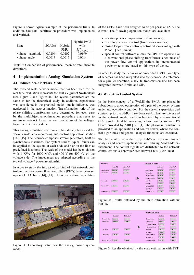
Figure 3 shows typical example of the performed trials. Inaddition, bad data identification procedure was implementedand verified.
Hybrid PMUState SCADA Hybrid with
PMU ISESCADA
voltage magnitude 0.0204 0.0202 0.0199voltage angle 0.0017 0.0015 0.0014
Table 2: Comparison of performance: mean of total absolutedeviations
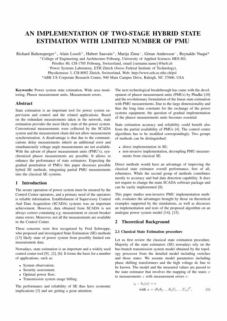
4 Implementation: Analog Simulation System4.1 Reduced Scale Network Model
The reduced scale network model that has been used for thereal time evaluation represents the 400 kV grid of Switzerland(see Figure 2 and Figure 4). The system parameters are thesame as for the theoretical study. In addition, capacitancewas considered in the practical model, but its influence wasneglected in the state estimation. Transformation ratio of thephase shifting transformers were determined for each caseby the multiobjective optimization procedure that seeks tominimize network losses, as well deviations of the voltagesfrom the reference values.
This analog simulation environment has already been used forvarious wide area monitoring and control application studies[14], [15]. The network comprises several generators, built assynchronous machines. For system studies typical faults canbe applied to the system at each node and / or on the lines atpredefined locations. The scale of the model has been chosenwith 1 KVA for 1000 MVA and 400 V for 400 kV on thevoltage side. The impedances are adapted according to thetypical voltage / power relationship.
In order to study the impact of all kind of fast network con-trollers the two power flow controllers (PFCs) have been setup on a UPFC basis [14], [11]. The series voltage capabilities
Figure 4: Laboratory setup for the analog power systemmodel.
of the UPFC have been designed to be per phase at 7.5 A linecurrent. The following operation modes are available:
• reactive power compensation (shunt source);• open loop current control (fixed series source);• closed loop current control (controlled series voltage with
P and Q set points);• special control software allows the UPFC to operate like
a conventional phase shifting transformer since most ofthe power flow control applications in interconnectedpower systems are based on this type of device.
In order to study the behavior of embedded HVDC, one typeof schemes has been integrated into the network. As referencefor a parallel operation, a HVDC transmission line has beenintegrated between Breite and Sils.
4.2 Wide Area Control System
In the basic concept of a WAMS the PMUs are placed insubstations to allow observation of a part of the power systemunder any operation condition. For the system supervision andcontrol up to five PMUs have been used. They are integratedin the network model and synchronized by a conventionalGPS signal. The data processing is based on the software PSGuard provided by ABB [12], [1]. The phasor information isprovided to an application and control server, where the con-trol algorithms and general analysis functions are executed.
The lab control is realized by LabView software; higheranalysis and control applications are utilizing MATLAB en-vironment. The control signals are distributed to the networkcontrollers via a controller area network bus (CAN Bus).
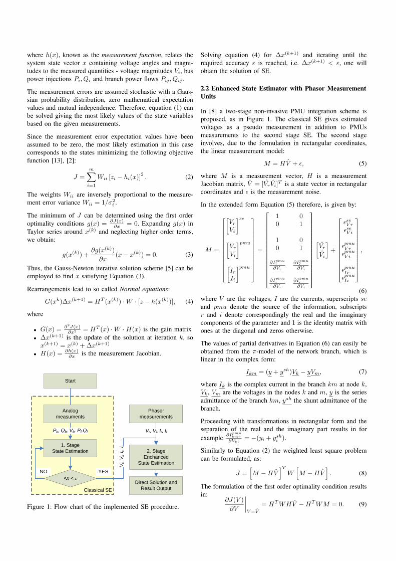
Figure 5: Results obtained by the state estimation withoutFACTS
Figure 6: Results obtained by the state estimation with PST
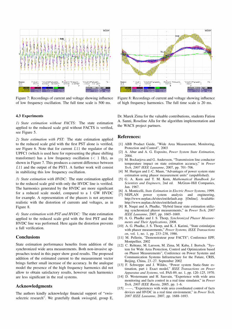
Figure 7: Recordings of current and voltage showing influenceof low frequency oscillation. The full time scale is 500 ms.
4.3 Experiments
1) State estimation without FACTS: The state estimationapplied to the reduced scale grid without FACTS is verified,see Figure 5.
2) State estimation with PST: The state estimation appliedto the reduced scale grid with the first PST alone is verified,see Figure 6. Note that for current L11 the regulator of theUPFC1 (which is used here for representing the phase shiftingtransformer) has a low frequency oscillation (< 1 Hz), asshown in Figure 7. This produces a current difference betweenL11 and the output of the PST1. A further work will consistin stabilizing this low frequency oscillation.
3) State estimation with HVDC: The state estimation appliedto the reduced scale grid with only the HVDC line is verified.The harmonics generated by the HVDC are more significantfor a reduced scale model, compared to a 1 GW HVDCfor example. A representation of the phasors is not anymorerealistic with the distortion of currents and voltages, as inFigure 8.
4) State estimation with PST and HVDC: The state estimationapplied to the reduced scale grid with the first PST and theHVDC line was performed. Here again the distortion preventsa full verification.
ConclusionsState estimation performance benefits from addition of thesynchronized wide area measurements. Both non-invasive ap-proaches tested in this paper show good results. The proposedaddition of the estimated current to the measurement vectorbrings further small increase of the accuracy. In the analoguemodel the presence of the high frequency harmonics did notallow to obtain satisfactory results, however such harmonicsare less significant in the real systems.
AcknowledgmentsThe authors kindly acknowledge financial support of “swis-selectric research”. We gratefully thank swissgrid, group E,
Figure 8: Recordings of current and voltage showing influenceof high frequency harmonics. The full time scale is 20 ms.
Dr. Marek Zima for the valuable contributions, students FatiouA. Sanni, Roseline Alla for the algorithm implementation andthe WACS project partners.
References:[1] ABB Product Guide, ”Wide Area Measurement, Monitoring,
Protection and Control”, 2003[2] A. Abur and A. G. Exposito, Power System State Estimation,
2004.[3] M. Bockarjova and G. Andersson, “Transmission line conductor
temperature impact on state estimation accuracy,” in PowerTech, 2007 IEEE Lausanne, 2007, pp. 701–706.
[4] M. Hurtgen and J.-C. Maun, “Advantages of power system stateestimation using phasor measurement units” (unpublished).
[5] G. A. Korn and T. M. Korn, Mathematical Handbook forScientists and Engineers, 2nd ed. McGraw-Hill Companies,Jun. 1967.
[6] A. Monticelli, State Estimation in Electric Power Systems, 1999.[7] NEPLAN power system analysis and engineering,
http://www.neplan.ch/sites/en/default.asp. [Online]. Available:http://www.neplan.ch/sites/en/default.asp
[8] R. Nuqui and A. Phadke, “Hybrid linear state estimation utiliz-ing synchronized phasor measurements,” in Power Tech, 2007IEEE Lausanne, 2007, pp. 1665–1669.
[9] A. G. Phadke and J. S. Thorp, Synchronized Phasor Measure-ments and Their Applications, 2008.
[10] A. G. Phadke, J. S. Thorp, and K. J. Karimi, “State estimlatjonwith phasor measurements,” Power Systems, IEEE Transactionson, vol. 1, no. 1, pp. 233–238, 1986.
[11] M. Pellerin, ”Demonstrateur pour FACTS”; Conference EPF,Montpellier, 2002
[12] C. Rehtanz, M. Larsson, M. Zima, M. Kaba, J. Bertsch. ”Sys-tem for Wide Area Protection, Control and Optimization basedon Phasor Measurements”, Conference on Power Systems andCommunication Systems Infrastructure for the Future, CRIS,Beijing, China, 23.-27. September 2002
[13] F. Schweppe and J. Wildes, “Power system Static-State es-timation, part i: Exact model,” IEEE Transactions on PowerApparatus and Systems, vol. PAS-89, no. 1, pp. 120–125, 1970.
[14] D. Westermann and H. Sauvain, “Experience with wide areamonitoring and facts control in a real time simulator,” in PowerTech, 2005 IEEE Russia, 2005, pp. 1–6.
[15] ——, “Experiences with wide area coordinated control of factsdevices and HVDC in a real time environment,” in Power Tech,2007 IEEE Lausanne, 2007, pp. 1688–1693.