an integration method of deriving the alternating current ... a.c.resistanceandinductance 95...
TRANSCRIPT
AN INTEGRATION METHOD OF DERIVING THEALTERNATING-CURRENT RESISTANCE AND INDUC-TANCE OF CONDUCTORS
By Harvey L. Curtis
CONTENTSPage
I. Introduction 93
II. Outline of the method 94III. Alternating-current resistance and inductance of a straight cylindrical
conductor 96
1, Derivation of formulas using real power series 96
2. Derivation of formulas using complex power series 103
IV. Alternating-current resistance and inductance of a return circuit 106
V. Application of formulas to experimental results 116
VI. Appendix: Evaluation of integrals and development of series 121
1. To expand log ^ in a Fourier series 121
^ , , cos na . -TA • ' f ^2. To develop ^— m a Fourier series of 6 121
3. Evaluation of the integral I^ 122
4. Evaluation of the integral I2 123
I. INTRODUCTION
The method heretofore used in deriving formulas for the com-
puting of the alternating-current resistance and inductance of
conductors requires the determination of the differential equations
of the magnetic field and the solution of these equations imder the
conditions imposed by the shape of the conductor. Formulas
have been derived for only a limited number of forms.
^
The method outlined in this paper is one of integration. It
requires that the conductor be divided into infinitesimal filaments
by surfaces which coincide with the lines of current flow. Themagnetic field at any point is the sum of the magnetic fields of all
of these filaments. The counter-electromotive force in a filament
is determined by the rate at which the magnetic fields of all the
other filaments cut this filament.
* The most important of these have been collected by Rosa and Grover, B. S. Bulletin, 8, p. 17a; 191 1;
Scientific Paper No. 169.
93

94 Scientific Papers of the Bureau of Standards [Voi. i6
II. OUTLINE OF THE METHOD
If small wires are placed side by side and an alternating electro-
motive force applied to their terminals, the current which flows in
any one of the wires will be determined not only by its resistance
and inductance, but also by the counteivelectromotive force
caused by the magnetic field of the others cutting this wire. If
there are only two identical wires, the current will be the same in
each. However, if there are three or more, they may be so
arranged that the counter-electromotive force in some is different
from that in others, thereby causing the current to be different in
different wires.
If the resistance and self-inductance of each wire are known and
the mutual inductance between the wires taken in pairs is known,
equations in sufficient number can be set up to solve for the ctirrent
and the phase of the current in each wire. For example, if there
are three conductors whose resistances are r^, r^, and fj, whose
self-inductances are Z^, l^, and /g, whose mutual inductances are
Wi2, ^23* aiid ^i3» ^^^ whose instantaneous currents are I\, I\,
and 7^3
:
^, r, idl\ dl\ dl\
'
=^'' '^ + ^^t/ +"^-7^ +^-"^'
dr, di\ di\dJ-^'^^^-dl-^'^^^-dJ
I\ n + k-^~ + W13-T-' + m,.
where
To solve, assume that
E' =E cos oit.
/'i=/i cos {(Jit~-<i>^)
I'2=12 cos (Cx)t—(f>2)
r^=h cos (o)t -</)j).
Substituting these values in the equation, there result three
TT
equations when w/ = o and three independent ones when oit-=-i
making six equations from which to determine the six unknownquantities; viz, the magnitude and phase of the current in each of
the three wires.
A solid conductor of infinite length may be considered as madeup of an infinite number of filaments, and each of these behaves as
though it were an infinitesimal wire carrying a current. The
Curtis] A. C. Resistance and Inductance 95
instantaneous cunent in any one filament is determined from the
equation
E^=r8j\+lo~^br^ + jJM.y |5/V, (i)
where E^ is the instantaneous electromotive force, r and /o the
resistance and self-inductance of the filament, 5 /'x the current in
the filament, M^y the mutual inductance between this filament
and another filament at Y in which the current is 8 I\. If there
are other conductois in the field, the integration must include these
also. Having determined 5 I\, the total current /' through the
conductor is the sum of those through the filaments, or
'-n'''^-n'''^'^(2)
where f/'x is the current density at x and dS an element of the
cross section of the conductor.
In equation (i), several of the quantities approach either zero
or infinity as the area of the element approaches zero. Hence it
is necessary to examine each term of the equation and to retain
only those which have a finite value.
In the term r 8 1\, r = -j^ and 8 I\ = U\ dS, where a is the resist-
ivity of the material, / the length and dS the area of the filament,
and U\ the current density. Hence r 8 I'^^ U\ <r/, which shows
that this term is a constant and independent of the area of the
filament.
The term /« -j. 8 I\ is the counter electromotive force caused by
the cutting of the filament by the magnetic field which the current
5 /'x sets up around and in the filament. If the filament becomes
infinitesimal, the current, and hence the magnetic field, is infini-
tesimal, so that in the limit this term becomes zero.
filament at X caused by the cutting of this filament by the
magnetic field which is set up by the currents in all the other
filaments. This is a finite quantity, although M^j becomes
infinite when Y approaches X. If analyzed mathematically, it
is found that this is a case where the integral of a function which
has one infinite point is a finite quantity.
The term | | Mxy -j. 8 1'j is the counterelectromotive force in the
96 Scientific Papers of the Bureau of Standards [Voi. i6
It follows that equation (i) may, by substituting for 5 /'y,
U'ydSy be written in the form
d U\E^^U^^al + jjM.y'^^dS. (3)
This equation may be used to determine the value of Z7'x in con-
ductors of known form, provided the necessary integrations can
be performed. Having determined L'^'x, equation (2)—viz,
/' =I I
Z7's c^ S—gives the total current in the conductor.
Equation (3) applies only to conductors which are so long that
the end effects may be neglected. To apply (3) to a particular
case, it is necessary to be able to express M^y as a function of the
distance between the filaments, and this can be done only whenthe permeability of the conductor is unity.
III. ALTERNATING-CURRENT RESISTANCE AND INDUCT-ANCE OF A STRAIGHT CYLINDRICAL CONDUCTOR
Formulas for the alternating-current resistance and inductance
of a straight cylindrical conductor of infinite length have been
developed by several investigators.^ In all cases they have
started from the differential equation of the magnetic field.
The method of integration outlined above has been applied to
this case to determine whether it will readily give useful results.
After the complete derivation using real power series had been
completed, it was found that the work might be much simplified
by the use of complex power series. However, the comparison
of the two methods is a matter of some interest, so that both are
given.
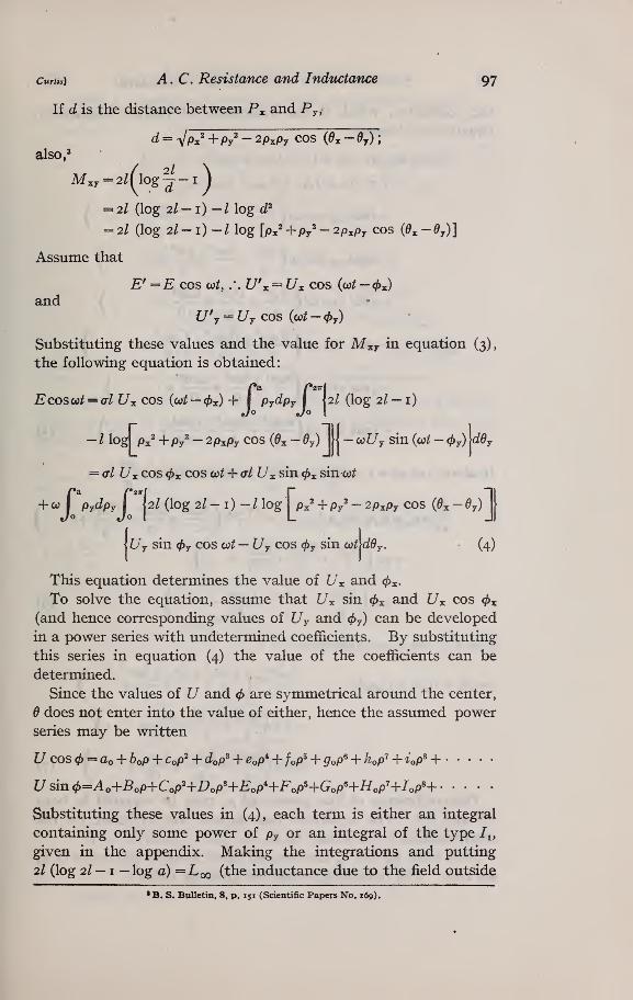
1. DERIVATION OF FORMULAS USING REAL POWER SERIES
Let Px and Py be any two points in the circular cross section of
a conductor of length /, and let Px 0^ and py By be the polar coordi-
nates of these points. ^ ^^^^
Fig. I.
—
The cross section of a cylindrical conductor, showing coordinates
* The different formulas and the methods of reducing from one to another are given in the paper by Rosaand Grover akeady referred to.
*
curits] A. C. Resistance and Inductance 97
If d is the distance between P^ and Py,
d = VPx' + Py' - 2PxPy COS (Oj, - dj);
also,^
= 2/ (log 2I — 1) —I log c^^
= 2I (log 2/ - 1) -/ log [px' +p/ - 2p^py cos (e^-dy)]
Assume that
E^ =E cos cot, .'. U\ = t/x cos (cot — <f)x)
andZ7'y = Z7y cos {0)t — (^y)
Substituting these values and the value for M^y in equation (3),
the following equation is obtained:
Ecoscot = <rl [7x cos (oj^ — 0x) + I PyC^Py I Ul (log 2I — 1)
— I log px^ + Py^ - 2pxPy cos (^x - ^y) [|—o)Uy sin {cot — (f)y)
\ddy
= <tI Z7x cos 0x cos cot + cl U^ sin ^^ sinat
+ O) I PydpyI
III (log 2/ - l) - / log Px' + Py^ - 2PxPy COS ((9x - ^y)
Uy sin <^y COS oot — Z7y COS <^y sin co^c^^y. (4)
This equation determines the value of ^x and <^x.
To solve the equation, assume that ^x sin ^x and Z7x cos <^x
(and hence corresponding values of Uy and <^y) can be developed
in a power series with undetermined coefficients. By substituting
this series in equation (4) the value of the coefficients can be
determined.
Since the values of U and 4> are symmetrical around the center,
B does not enter into the value of either, hence the assumed power
series may be written
Z7 cos = ao + bop + CoP^ + dop^ + Cop^ + /oP^ + gop^ + Kp'^ + iop^ +
L^sin0=Ao+^oP+Cop'+I^oP'+£:oP^+FoP^+GoP«+//oP'+/oPH
Substituting these values in (4), each term is either an integral
containing only some power of py or an integral of the type I^,
given in the appendix. Making the integrations and putting
2/ (log 2/ — I —log a) = Loo {^^^ inductance due to the field outside
•B. S. Bulletin, 8, p. 151 (Scientific Papers No. 169).
98 Scientific Papers of the Bureau of Standards [Voi. 16
the conductor, which is the inductance at infinite frequency;,
equation (4) becomes
E cos oit = al cos o)t{ao + Z>oPz + CoPx^ + }
+ al sin o}t{Ao-\-BoPx + Copx+ }
_ /Aoa',Boa'
,Coa'
.
\+ 27rcoLoo coscon 1 1 1- j
— 27rwLoo smco/i 1 1 1- )
\ 2 3 4 /
. /Aoa' Boa' Coa* \+ 47rcol cos con 1 1 ^+ )
V 4 9 16 /
7JAoP.' BoP/ CoP.' \— Airm cos cot I 1 1 ^- + I
V 4 9 16 /
. /aoa^,60^'
, ^o aV \
V 4 9 16 /
+ 4^^^ sin ^^(^-^ +— +-75-+y
(5)
If ost ««= o, COS CO/ = I , and sin co/ = o, then putting rj =—
^=ao+6oPx+coPx^+•
• • +—r-V"!" -^T ^-T"^ )
^ /Aoa'Boa' Coa* \+ 4171 1- +—7-4- • • • I
\ 4 9 16 /
TT
If CO/ = - » COS CO/ = o and sin co/ = i
2
o=Ao+5opx+Copx^+ ^—(
-^ ~r"^~4~ —
/
/aoa^,^oa^
,Coa*
.\
V 4 9 16 /
+4.(^+^V-f+....) (7)
The coefficients of like powers of Px may be equated in both
(6) and (7). The equations thus formed are sufficient for the
determination of the values oi Ao, Bo, Co . . . andao, Ky Co . • . .
Since both Bo and bo are zero, all coefficients of odd terms of p,
are zero. The remaining values are given in Table i
.
curtts] A, C. Resistance and Inductance 99
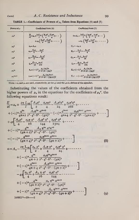
TABLE l.^<}oefficients of Powers of p^ Taken from Equations (6) and (7)
Power of p Coefficient from (6) Coefficient from (7)
Px" ^r^-'-^i^-^-f- •) „ ^ 27,Loo/aoas. Coa<
.
0=Ao^ (^ 2 + 4 -^• •)
, ..,(^%^V.. ) /aoa2 Coa< ^^ \
4„ ^ 4 ^ 16 t • • •
;
P.« Co=AoJ7 Co=-ao77
Px<„ Co »7 Ao *?'
Eo 4-4Px« 8°'"
9 36
Co 77 aoij»^° 9 = 36
Px8 ^ 16 576J
gol7„A„„*16 576
p,to x„=( 1)° ^"^^"^'^° ^ ^ 22. 42. 63- -(to)!
V , ,^n Ao(4»;)2»^-C 1) 22.4^.6»..(4n)»
Px^+2 '^ > 22.42-62--(4n+2)«
Note.—xo and yo are used, respectively, as the ^n and the 4W+2 letters of the alphabet.
Substituting the values of the coefficients obtained from the
higher powers of Px in the equations for the coefficients of Px°, the
following equations result:
(tIao +
217 L 00
/
[AoO^ aooa'^ Aoffa^ aori^a^~~2
4247""^ 288 "^
+ (-i)n4^A off'' a^'^^^
(-1)'
2n+l /i4n+4aoV a
4^+2 2^ •4^-6^ •• (4^)2 4W+4 22-42-6^- • (4n+2)^
^14 16 144 2304
4'^ Aq ??^^ a%-^^
]
o=Ao-
(4W + 2)2 2^• 4^ •
6^•
• (47i)
•
i2n+l 2n+l /,4n+4ao??"""* a
(41^ + 4)22=^.4'. 6'-. (4n + 2)
27? Loo
+] (8)
/ tap a^ ApTf a* apYj^ a"
2 4 24
+ (-i) n 4^ aor;2^a^^+2
+ (-!)'
^n + 2 22-42 •62-• (4^)2
4^ + 4 22 -42 •62- • (4ti + 2)'
tttoa2 Ao 17 a'^ aprf a"
+]
+ (-i)^ap 772^ a4n+2
(4^ + 2)2 22.42.62. -(4^)2
(9)
148921°—2(

loo Scientific Papers of the Bureau of Standards [Voi.x6
In order to simplify these equations, the following substitutions
niay be made:
^ 72^ ^'^ ^^ n + i 22.42-62... (4^1 + 2)2^ •••• ^^^
^ 144^ ^^ ^^ (n + i)'22-4'-62-. -(4^ + 2)2^••••
'
i-j2"^'**"^^ !>> (2n + i) 22-4=^-62.-- (47^)2^•••• ""^
Then equations (8) and (9) become
Solving for ao and >lo
''^^Vi
n'a'LJV, 7,'a'X,
£ 2/
_ 9 r "\ 7"
Since the current, 5 Z^', through the filament at P^is Z7x'PxC^Pxfl^^x,
the total current /' through the conductor at any instant is given
by the integral
^'-{^^^-'={^^- Px c/Px de^'
= I Px c?px I (ao + Co Px^ H- • • • • ) cos co^
4- (Ao + CoPi' + ) sin ojM J ^x
Integrating
T, ^ / X /aoa^ Coa* \/'=/cos (co^-</)) =2x( -^+-^— + jcos w^
+ 27r ( + + jsm w^ (12)
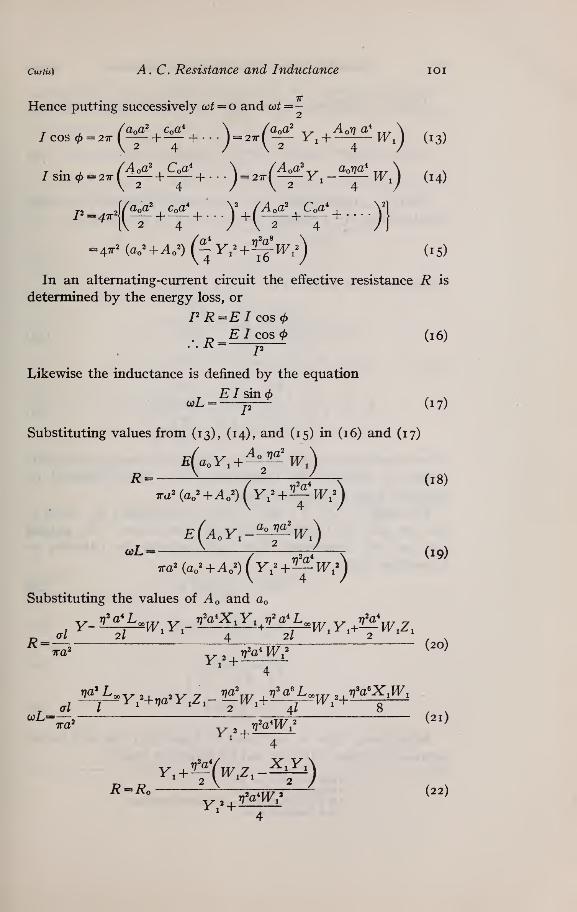
Curtis] A. C. Resistance and Inductance loi
Hence putting successively 03t = o and oot=-
/cos0 = 27r(-y+— + . .
.J= 27r( — Y, + -~~W,) (13)
/sm,^ =a.(4f +^V...) =..(^V,-M?!w'.) (14)
P„,,.j(^V^V . . .
J+(^ +C^V . .. .
Jj
=4tM«o^+^o^)(^V,^+^W-,^^ (15)
In an alternating-current circuit the effective resistance R is
determined by the energy loss, or
P R=E I cos <f)
. „ E/COS0 (16)• • ^= p
Likewise the inductance is defined by the equation
. EI sin (f)^L =j^ (17)
Substituting values from (13), (14), and (15) in (16) and (17)
E(a.Y,^^w)R = ^ 7 ^ \ (18)
e(a.y,-^-^w)coL = ^ ^
y -i^^-T (19)
ira' (ao'+A,') Iy^+^-^ W,')
Substituting the values of Ao and ao
al 2/ ' ' 4 2/ ' ' 2 ^ '
K= --——o 4 TT7 2 (20)
' 4
^ al I ^ ' * ' 2 ^ 4/ ^ 8 , .
ajL=—», .xx/o (21)
'^4
^ =^ ^o— .2.4M/ > (22)
1^1^ +
I02 Scientific Papers of the Bureau of Standards {Voi.i6
Where Ro, representing the direct current resistance, equals —-
Tza
'^4
Where L^, representing the inductance at infinite frequency,
equals 2/ (log 2I — 1 —log a) and co is given by the equation
err;— = co.TT
Substituting the values oiW^, X^, Y^, and Z^
I +V-+V + -5^— +r)_o 6 480 1 81440
1+-^— +-^^ + ^ ^ +12 1440 725760
, I +-^+-^ 4-—^ +r_r / 24 4320 2903040
^2 Ty^a^ r;^a« ty^a^^(25;
12 1440 725760
These correspond exactly with the asymptotic formulas of Russell.*
Tables to facilitate the computation have been published by
Savidge ^ and by Rosa and Grover.®
The series W^, X^, Y^, and Zj may be expressed in terms of
the ber and bei functions and their derivatives. By putting
q^ = ^ria^, and comparing them term by term, the following re-
lationships hold:
W,= -^h^r^q (26)
X, = |^(i-ber^) (27)
Y, = |bei'g (28)
Z, = ^heiq (29)
Substituting these in equations (22) and (23), the well-known
solution in terms of the ber and bei functions result.^
* Phil. Mag., 17, p. 534; 1909.
» Phil. Mag.. 19, p. 49; 1910.
• B. S. Bulletin, 8. pp. 173-136 (Scientific Paper 169).
' B. S. Bulletin, 8, p. 175.

Curtis] A. C. Resistance and Inductance 103
Therefore, for a circular conductor, the method of integra-
tion gives results identical with those obtained by previous
investigators.
2. DERIVATION OF FORMULAS USING COMPLEX POWER SERIES
The derivation of the formulas may be much simplified by the
use of complex quantities.
Leti«t ,
,, J. Ji(«t-0) dU^ . J J
i{u,t-4>)
Where
Substituting in (3) , viz
:
E
Et' = <7iuJ^\-'^ f(M.yic,uJ'''r'^dS
Take out e'" and insert the value of
Mxy = 2/ Hog ^-lj = 2l (log 2l-i)-l log d'^
E = <TlUy,e' ^+ta) I pjdpj
I 12/ (log 2/ — i)
(30)
-/ log [p,2+p^2_2p^p^ COS {e^-e^u,e "^de^ (31)
Assume^7,€"'^^ =A +5p, + Cp,2+L>p,3+ . ...
Where A, B, C, D,,etc., are complex numbers.
Substituting in (31) and putting
E = <jI(A +Bp^ + Cp^'+Dp^'+),
. , rAa',So' Ca' "I
+4,,,/|^_+_ +_ +....J
-K¥-^^^— •](3.)

I04 Scientific Papers of the Bureau of Standards
When Pi = o
^ ,, . , VAa-" Ba' Ca' 1
"L 2 3 4 J
. TAa' Ba' Ca' "1
iVoL i6
(33)
TTCO
Equating the Hke powers of Px and letting — = 77, the values
of all the coefficients may be expressed in terms of A as indicated
in Table 2
:
TABLE 2.—^Values of Coefficients of Powers of p^ in Terms of A from Equation (32)
Powers of p Coefficients
P. B=0
P«» a/C=AIa>W cJ'-'^-,,A
P.« D=0
P>< ./E-^*;-'a.»^iA v*A
P>> F=-0
Px« WG-^'r'la,3x3A_ I,»A
^ 4-9<rJ (3I)«
Pk' H-0
Px" _ GlcoW'^•'
16
a,«^4A ^4A4.9-16a< (4I)>
Px^-1 Q-0
Px2" l-„-A
Note.—Q and R are used, respectively, as the an-i and an letters of the alphabet.
Substituting these values in (33)
:
* L2 4 24 288 (?z!)2(2n + 2) J
. ,.ra\ir)a' rj^a^ iri^a\,
^'^r7^a2^+2 -|
^|_4 16 144 2304 [n!(2n + 2)P J
^'^^
To determine the total current through the conductor
=I\^dp^ \e'-KA + Cp^' +Ep^' +--')de^
Jo Jo
Integrating
:
r a t ^^ :y^^' Ca' Ea' \
V 2 4 6 /

Curtis] A. C. Resistance and Inductance 105
Simplifying and substituting values of C, £", etc., from Table 2
:
r i^ a/"^^ ,^Va^ V^^^ ^V^^^
,
^^^^^. \ / ^
/e-.* = 2x^(^-+— -—-^ +^^ + --j (35)
E' EAlso ~jr=R + io)L, or ~-z:r^=R + iccL (36)
Letting Pl^i, Xi, Yi, and Z^ represent the same values as before,
then substituting from equations (34) and (35) in equation (36)
:
irja^WiRationalizing the denominator by multiplying by Y^
and taking the real parts
.^ , ^na'X.Y,
. , ,naW,Z,
R ^-4 ——^ ? (38)
Letting—2==-^o
^ ^rl^W^_rMX^
R = ^- ^, ,„., ^ (40)
In like manner
^=-L» + - TTw^^ (41)2 5WV
'"*"
4
These equations are identical with (22) and (23) showing that
the result using complex power series is the same as with real
power series.
io6 Scientific Papers of the Bureau of Standards Wol.x6
IV. ALTERNATING-CURRENT RESISTANCE ANDANCE OF A RETURN CIRCUIT
INDUCT-
If a return circuit consists of two parallel cylindrical conductors,
whose length is great compared to the diameters of the wires and
to the distance between them, the method of integration can be
applied to the determination of the alternating current resistance
and inductance of the circuit.^ If the wires have the samediameter, the current distribution in one wire is symmetrical
about the line joining the centers of the two wires. If the equation
of current distribution is given in polar coordinates, it will be
identical for the two wires if the angles are measured from the line
joining the centers of the wires.
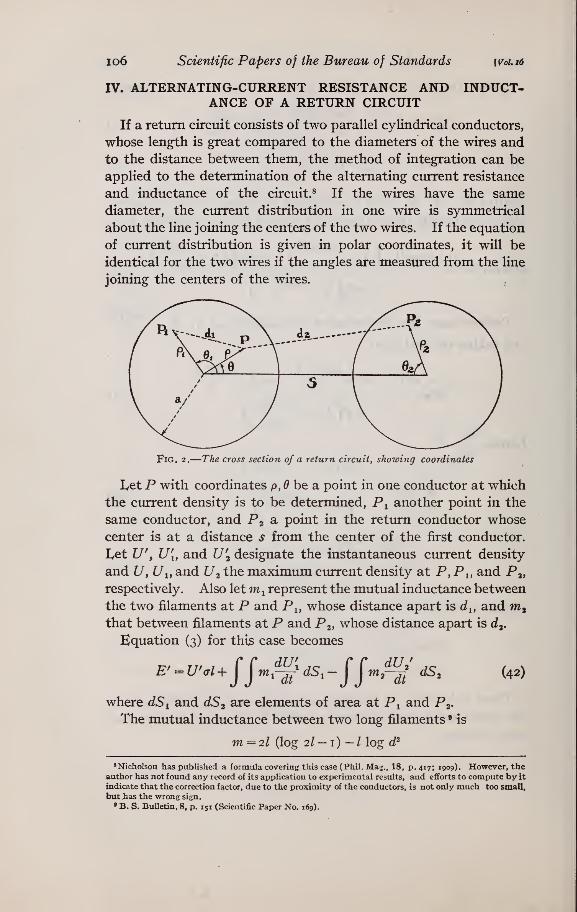
Fig. 2.
—
The cross section of a return circuit, showing coordinates
Let P with coordinates p, ^ be a point in one conductor at which
the current density is to be determined, P^ another point in the
same conductor, and P2 ^ point in the return conductor whose
center is at a distance s from the center of the first conductor.
Let U\ U[, and U^ designate the instantaneous current density
and Z7, U^, and U2 the maximum current density at P, Pi, and Pj,
respectively. Also letm ^ represent the mutual inductance between
the two filaments at P and Pj, whose distance apart is d^, and m^that between filaments at P and P2, whose distance apart is d^.
Equation (3) for this case becomes
E' = U'cl + jjfn,^" dS, -fjm,^' dS, (42)
where dS^ and dS2 are elements of area at Pi and Pg.
The mutual inductance between two long filaments • is
m =2/ (log 2/ — i) / log d'
^Nicholson has published a formula covering this case (Phil. Mag., 18, p. 417; 1909). However, theauthor has not found any record of its appUcation to experimental results, and efforts to compute by it
indicate that the correction factor, due to the proximity of the conductors, is not only much too small,
but has the wrong sign.
» B. S. Bulletin, 8, p. 151 (Scientific Paper No. 169).

Curtis] A. C. Resistance and Inductance 107
Substituting values of m^ and m^ in (42)
E' = U'Gl + 2l (log 2/- 1) r r^^' dS,-l{ flog ^1'^'' ^5i
-2/ (log 2/-1)JJ^^'
JS^ + zJJlog c^,^^^' ^5, (43)
Since the current in the two conductors is the same,
^ {u\ds,= { {u'.ds,.
So that terms two and four of the second member of (43) cancel.
But E' =Ee-\ U' = ^e^C^t-.^), Ui = ^^e^^"*-^^), etc.
^i'=P^+Pi'-2pPiCOS (^-^1)
d^ = {s — p COS ^ — p2Cos^2)^ + (p sin ^ — P3sin B^^
= 9' + P2' - 2gP2 cos {a - e^),
where q cos a=s — p cos 6
and q sin a = p sin ^
so that q^=s^ — 2s p cos ^ +p^
Hence equation (43) becomes
E=^(tIU€-''^
f*a. r2T
-ioill p,dp,\ log [p^+p,^-2pp^ cos (6-6,)] Ui€-''^'deiJo Jo
+ ioil I p^dp^\
log [q^+P2 - 2gP2 cos (« -6^)] U^e'^'^'dd^ (44)Jo Jo
Both L^ and are functions not only of p but also of 6. But as
L^ and </> have the same values for — ^ as for 6, the functions of
6 when expressed in a Fourier series will be in terms of the cosine
series only. Hence, assume
^€-i<^ = ao + «! cos 6 +a2 cos 26+
+ p(6o + ^1 cos ^ + 62 cos 2^ + • • ••
)
+ P2 (co + Ci cos 6 + €2 cos 2(9 + • • • •
)
^^"^^
+ ••()
If these values are substituted in (44) and the integration per-
formed, a comparison of coefficients shows that many vanish.
Equation (45) reduces to the following:
Ue-'"^ = ao + CoP' + eoP' + goP'+
+ (6iP+c^iP'+/iP'+ • •) cos^
+ (c2P^ + e^p^ + g^y + • • ) cos 28
+ (d,p' + f,p' + h,p'+--) cos3(?
+ (e,p' + g,p' + iy + • • ) cos 4(9
+ ( )
(46)
148921°—20 3
io8 Scientific Papers of the Bureau of Standards [Voi.16
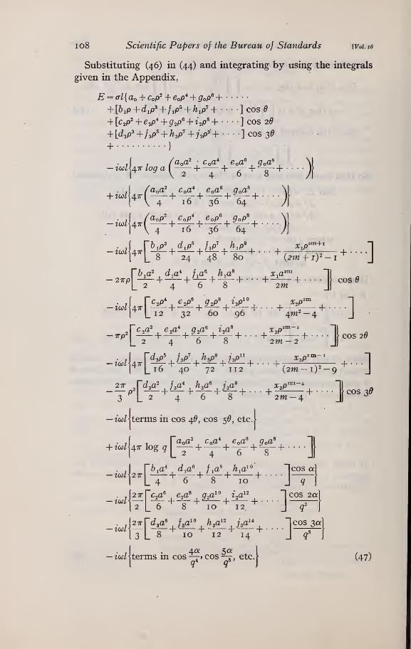
Substituting (46) in (44) and integrating by using the integrals
given in the Appendix,
E = (Tl{ao + CoP^ + Cop^ + QoP^ ++[b,p+d,p^+f,p^ + h,p'+ ] cos^
+ [C2P^ + e^p"^ + g^p^ + ^2p^ +••••] cos 20
+ [d,p' + fsP' + h,p' + ;>« + • • ] cos 3(9
+}
f /aoa^ Coa*,Coa^ Qoa^ \[-^c^l\4^logai^— +— +~^ +— + • • • •
J|
. A Vb.p^ d,p^ f,p' h.p'' x^p'^^^' l
r L 8 24 48 80 {2m-\-iy-i J
I |_ 12 32 60 96 /\.nr—^ J
-7rp2 -^ +^- +^ + -V+-- •+-^^ +•••• cos 2(9
|_2 4 6 8 2W-2 J)
~zco/ 4x -^4-'-^ + -^+-i5^+. . . +- ^^^— +• • •
[ [_ 16 40 72 112 (2m — 1)2 — 9 J
Z [_ 2 4 6 8 2m -4 J ^
— tco/jterms in cos ^6, cos 5^, etc.[
+ zc./J4^ log q [^— +-_ +^ +-y + ...
.J
. A2irrc2a^ e.a^ q.a^^ i.a^^ "1 cos 2q;1
( 2 [_ 6 8 10 12 J ^ )
3 L 8 10 12 14 J
cos 30:
ico/jterms in cos —^» cos —j, etc.[ (47)
Curtis] A. C. Resistance and Inductance 109
By equating to zero the coefficients of like terms of p and^, manyof the undetermined coefficients are easily evaluated. The most
important of these are given in Table 3
:
TABLE 3.—Coefficients of Terms Involving p and 6 from Equation (47)
TTCO
Let
—
=v(T
Coefficients of— Values obtained Coefficients of— Values obtained
P» Co= i7;ao p^cos 2d „ ii7C262=-3-
P* IrjCo TJ^aoeo=-4—
—
p^cos 26^- 8 24
"' ^ it/eo i7??3o«•"
9 35 pScos 29 . i7?g2 i77^C2
^^ 15""
360ffi
*" 16 576 piocos 29
^»-2?-8640plO iTjio i77=ao
*^*'°"25 14400 pl2C0S 29 _ i7jk2 i775c2
"^'^35 ^302400
pU ivyko 7?^ao"^o"
36~
518400 places 28
48 14515200p»COS<?
d,-^''^^^ 2 P^cos 3^
b-'fp'COSff
^' 6 12 P'cos 35 ^-'-^'-'^picas B
^^-12 144 p9C0S 35
'^ 18 720pScos e iTjhi Tj^bi
" 20 °"2880 piicos 35, ivk V*d3li= —^-^=——
-
^ 28 20160pllCOS^
*^ 30 86400 piscos 35 i^l3 irjSds
^ 40 806400piscos e i»?li ^«bi
°^ 42 3628800 piscos 35 l77n3 r;«d3
^^ 54 43545600
Substituting the values from Table 3 ,- the series in equation (47)
containing powers of the radius, a, reduce as follows:
2468a,a\coa* e,a\g,a\4 16 36 64
af,a'
2 12
~744
"^ 2880 86400"''
aoaT trya^ rj^a*I +-—
36
t77^a^ ?7%^ ^T7^a^^+ -^^ + —4^ +
576 14400 518400
2'^4"^6'^8"^"" 2L4t7]a^ rj^a^
36
ir]^a^ Tj^a^ irj^a^^
576 14400 518400

no Scientific Papers of the Bureau of Standards
c^ e^a^ g^ ijP^ ^c^a^V irja^ rfO*"
2 4 6 8 ~2L 6 72
irfa^+
77%^+
ir^V^
1440 43200 I 514400
24.68 2 L
ii7a^ 77^a*
^r;^a^ ry'^a^
+ +
120
61a* d^a^ f^a^ h^a^^
4 6 8 10
2880 100800 4838400
^—1 I +-3 24f[
irfa^ ri^a^ irj^a^^
360 8640 302400
6 8 10 12 6L440720 20160 806400
+
dsa\isa'\ha'\ua'' d,a'— \-- 1 p . . . . = —
—
8 10 12 14 8I +
irja^ 77-a*
S 60
irj^a^ 7]^a^ irj^a^^
1260 40320 I 814400
[Vol. 16
_c^a'= 2 ^0
-'-fD^
^h,a^
= 6^^
.¥^.
It will be noted that the series are all arranged so that the first
term is unity. It can be shown that they are all converging series.
Substitute the series given above in (47) and retain only the
constant terms and those of the form p^ cos nd, since the coefficients
of all other terms are zero. Also insert expansions of log q, of
cos a .cos 2a • • ^t, a- t^ a.'^^ ^u
» of ^— > etc., as given m the appendix. Put -q = — . inen
al= aQ + b^p cos 6+C2P^ cos 2d + d^ p^ cos 3^+ • • •
•
— irj[2aQa^AQ log a — aQa^A^ — b^a^A^p cos 6— c^a^C^p^ cos 26
-—d^a'D,p^ cos 3(9+- •]
o
+ ir][2aoa'A, (logs- j cos ^-^^ cos 2^ -^3 cos 3^ )]
-ir]\ ——^
2 3 "1
(l + —COS e + ~ cos 2^+^COS 3^+ • • •)S o O _J
2p 3P 4P^(l + ^ COS ^ +^ COS 20+-^ COS 3^+ • •)
]3P 6p I op'
(1+ -^-cos6'4--V cos 2^+-f-cos 3^+- • •) (48)]
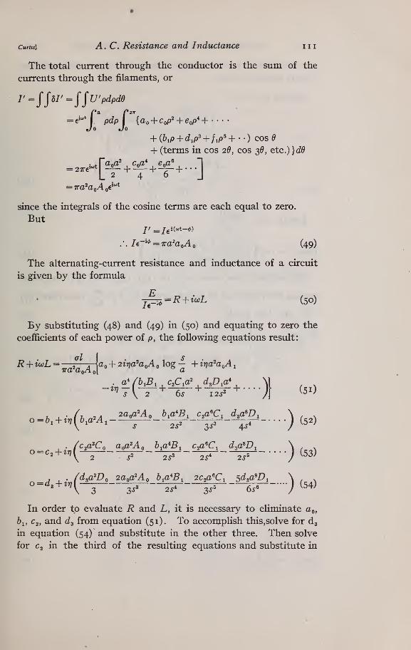
curtts] A. C. Resistance and Inductance iii
The total current through the conductor is the sum of the
ciurents through the filaments, or
r=^^hr=^^u'pdpde
= e^-'l pdpl {a, + c,p'+e,p'+--'-Jo Jo
+ {b,p+d,p'+f,p'+'-) cos (9
+ (terms in cos 20, cos 3^, etc.)}c^^
since the integrals of the cosine terms are each equal to zero.
But
.'. Ie-''^=Tra'a^Ao (49)
The alternating-current resistance and inductance of a circuit
is given by the formula
j^, = R+io:L (50)
By substituting (48) and (49) in (50) and equating to zero the
coefficients of each power of p, the following equations result:
R + uaL =—2
—-r-\(io + 2ir]a^aQA log — + irja^a^A
jTra aQ/\ ot ^
,. (c^a'C^ a^a^A^ h-fl^B^ c^a'C^ d^a^Dj \
o = c, + tn{^—-J,
—, —, —, j (53)
. /d^a'Do agpa'Ao b^a^Bi ac^aTi S'^so'D, \o=d, + tv\^— —,
^^5~, ^, j (54)
In order to evaluate R and L, it is necessary to eliminate a©,
61, C2, and ds from equation (51). To accomplish this,solve for dg
in equation (54) and substitute in the other three. Then solve
for C2 in the third of the resulting equations and substitute in
112 Scientific Papers of the Bureau of Standards {Voi i6
the other two. In this way the eUmination may be accomplished.
This is outhned below.
Solving (54) for d^
. /2aoaMo .b^a^B^ 2c^a^\
/2a^^Ao b^a^B^ 2C2a^CA
Bi-
ds
17]
3iva^Di(55)
6s'
Substituting this value of d^ in (51), (52), and (53) and repre-
senting the resistance to direct current by Rq =—^» equations (57),7ra
(58), and (59) result.
R-hicoL I I • , ^ , <y . , >.—-^— =X~a\ ^' "^ ^'^va'aoA log - + tva'^a^
,
-irja^ rb.B^ a^c^C^ i'(]a^DJ2a^^ b^a^BXV[ , x
s L 2 66- "* I2y» \2,s^D^'^ 2s'Dj]\ ^^^^
o^b.^i\a^b.A.-'-^-'^^^ (58)
o-r ,
,• ( ^o^'-^o b.a'B, c,a'Co c.a'CA
Solving (59) for c.
( , ,
b,a'B\
\ 2 26-^ /
^2=
"^—Tr -^ir^ (60)
1 + i-na^
\ ^
ir}a^Ci
^1 ^r;aY . ,b^a^BA ., .
then c, = ;j:^^(^^oA + ^^) (61)
Curtis] A. C. Resistance and Inductance
Substituting the value of c^ in equations (57) and (58)
= -7- + -^— + 2ir)a^ log -R. A, Ao 'a
irja*(i-qaQa^A^D^ i'qh^a^B^D^
sa.A, i8^^D. 24J-^Dj
^i-^iA tW^I^A,
a^Cyirja^a
^ 2 y'^4s'Dj'^ 6s \ s'C
o = bi + ir]bia^Ai —i'qh^a^B^ ^irjaoa^A
2S
irja'^Ci /irjaQa^A q irjbia'^BiX r)^a(,a^ ^D ^.
3S' V ^'C^"^
2S^C:, )^ 6?D~
Solving (63) for h^,
2ir]a(,a^AQ 'r)^a^,a^A^yC^ r/^aoa^MoZ^i
biSs'C, 6s'D,
,,<,,,,„!^,5|^,
T 4- o 1 ,• 2Z1
iva'B.n'a'^B.C,Let ^2 = 1 + tr?aM 1 ^ +
2i"'
then
^1 =
Ss^C^
2ir]a^a^AQ Ty^aoaMoCj rj^aQa^^AoDi
sB, Ss'B^C^ es'B^D,
substituting the value of 61 in equation (62)
R-\-io:L l+irja^A, . ,, s-^— =—̂ ^^+2zr;aMog-
ir}a^{''2i7]a'^ rfa^C^ yfa^^D^^
5i irja^B^Ci irja^B^Di irja^B^D^+
I2i"*C,+
Ss'D..+
24,^'
6s'C, ^iSs'D,
irja^A. . , , s—. + 2it]a' log -/in Cl
irja'^liTja^D^
i-qa'^B^ rj^a^BjCi irja^C^]
7~\i8s'D,'^ B, ~ 3s'B,C,'^'6?C~2\
113
(62)
(63)
(64)
(65)
(66)
(67)
(68)
114 Scientific Papers of the Bureau of Standards [Voi. i6
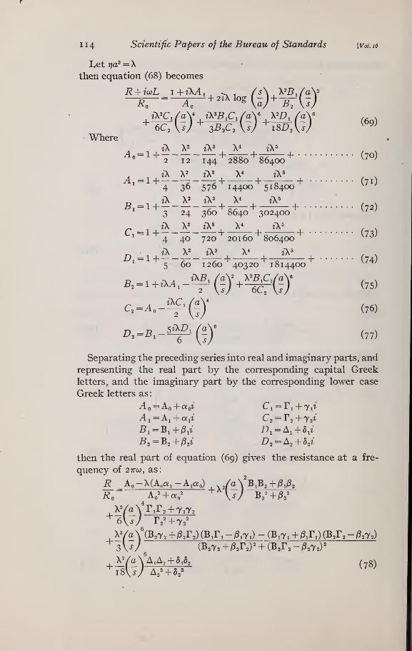
Let rya^ = X
then equation (68) becomes
• Where
2 12 144 2880 86400 ^' ^
Ai = l+ 7 2+ +o + (71)
4 36 576 14400 518400
„ , iX X2 tX^,
X^,
iX^ -
,
3 24 360 8640 302400 ^' ^
c..i+!^-^-i=^+-^ + -4^+ (73)4 40 720 20160 806400 ^
^ i\ V i\' X* i\' ,,
5 60 1260 40320 I 814400
„ , .^ , iKB^ (a\ \^B^CJa\ ,,
2
^-^'-^'(7)' (77)
Separating the preceding series into real and imaginary parts, and
representing the real part by the corresponding capital Greek
letters, and the imaginary part by the corresponding lower case
Greek letters as:
Ao = Ao + a:o'Z'' Ci = ri + 7it
A 1 = Ai + Qiit C2 = Ta + 72^*
^2 = B2 + i^a^' 1^2 = ^2 + h^i
then the real part of equation (69) gives the resistance at a fre-
quency of 27ra;, as:
/aYB,B2+^,/
^^\S) B2^+^2^
i? Ao-X(AoQ;i-A,q!o) /a\ B,B2+i3A
4
xYaVrir2+7iT26V^y r2^+72=
XYaY(B2T2+fe
3V/ (B2T2+iS2r2)^ + (B2r2-/32T2)
18V/ A
_^.- ,.(B2T2+^2r2)(B,r,-iS,7i)-(B,7i + ^:r,)(B2r2-/52T2)
--^ '^ ' % ^U2
A-- + ^A (y8)2+52
Curtis]
Since
A. C. Resistance and Inductance
coL __ Lircoa^ _ Lrja^ LX
115
al I I
the imaginary part of (69) gives the inductance at a frequency of
27rco, as
AoAL = 2/log-+/
a
.+ao(«i--|)
Ao^+OJo'+ /X
ifi-iB2-BA
/X/aVvi'^6\sri
^ l\Ya\\B,T,-^,y,){B,}
3\V (B272
T, - p,7,) + (B,7i + g,r,) (B372 + ftr^)
(79)
It should be noted that the values of R and L as given in equa-
tions (78) and (79) are for one of the conductors of a return circuit.
The total resistance and inductance are twice these values.
Although equations (78) and (79) give the alternating current
resistance and inductance of a retimi circuit at any spacing of the
wires, yet the series involved are not convergent for high frequency
with large wires very close together.
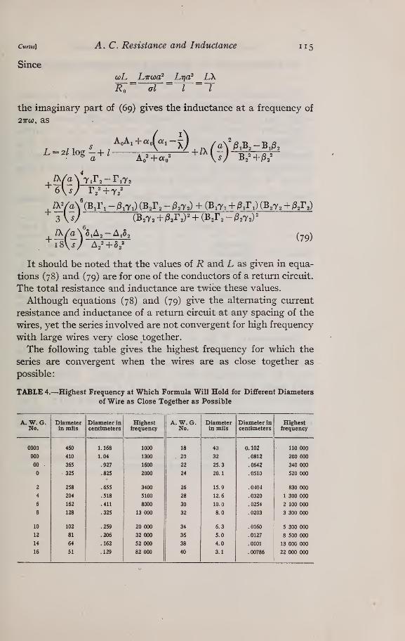
The following table gives the highest frequency for which the
series are convergent when the wires are as close together as
possible
:
TABLE 4.—Highest Frequency at Which Formula Will Hold for Different Diameters
of Wire as Close Together as Possible
A. W. G.No.
Diameterin mils
Diameter incentimeters
Highestfrequency
A. W. G.No.
Diameterin mils
Diameter incentimeters
Highestfrequency
0000 460 1.168 1000 18 40 0.102 110 000
000 410 1.04 1300 . 20 32 .0812 200 000
00 365 .927 1600 22 25.3 .0642 340 000
325 .825 2000 24 20.1 .0510 520 000
2 258 .655 3400 26 15.9 .0404 830 000
4 204 .518 5100 28 12.6 .0320 1 300 000
6 162 .411 8000 30 10.0 .0254 2 100 000
8 128 .325 13 000 32 8.0 .0203 3 300 000
10 102 .259 20 000 34 6.3 .0160 5 300 000
12 81 .206 32 000 36 5.0 .0127 8 500 000
14 64 .162 52 000 38 4.0 .0101 13 000 000
16 51 .129 82 000
1
40 3.1 . 00786 22 000 000
ii6 Scientific Papers of the Bureau of Standards [Vcl. i6
V. APPLICATION OF FORMULAS TO EXPERIMENTALRESULTS
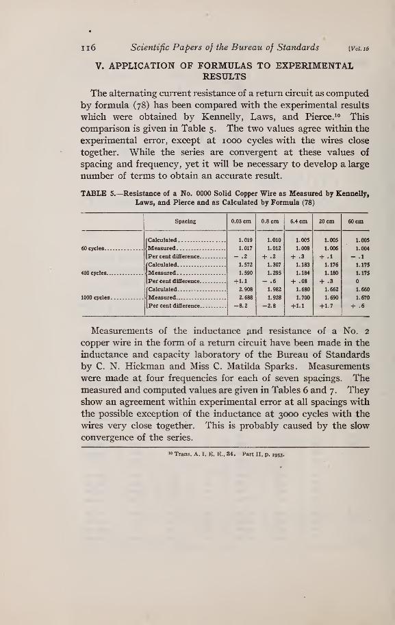
The alternating current resistance of a return circuit as computed
by formula (78) has been compared with the experimental results
which were obtained by Kennelly, Laws, and Pierce. ^<^ This
comparison is given in Table 5. The two values agree within the
experimental error, except at 1000 cycles with the wires close
together. While the series are convergent at these values of
spacing and frequency, yet it will be necessary to develop a large
number of terms to obtain an accurate result.
TABLE 5.—Resistance of a No. 0000 Solid Copper Wire as Measured by Kennelly,
Laws, and Pierce and as Calculated by Formula (78)
Spacing 0.03 cm 0.8 cm 6.4 cm 20 cm 60 cm
[Calculated 1.019
1.017
- .2
1.572
1.590
+ 1.1
2.908
2.688
-8.2
1.010
1.012
+ .2
1.307
1.295
-.61.982
1.928
-2.8
1.005
1.008
+ .3
1.183
1.184
+ .08
1.680
1.700
+ 1.1
1.005
1.006
+ .1
1.176
1.180
+ .3
1.662
1.690
+1.7
1.005
60 cycles Measured 1.004
Per cent difference — .1
fCalculated 1.175
400 cycles 1.175
[Per cent difference
(Calculated 1.660
1000 cycles 1.670
Per cent difference + .6
Measurements of the inductance ^,nd resistance of a No. 2
copper wire in the form of a return circuit have been made in the
inductance and capacity laboratory of the Bureau of Standards
by C. N. Hickman and Miss C. Matilda Sparks. Measurements
were made at four frequencies for each of seven spacings. Themeasured and computed values are given in Tables 6 and 7 . Theyshow an agreement within experimental error at all spacings with
the possible exception of the inductance at 3000 cycles with the
wires very close together. This is probably caused by the slow
convergence of the series.
10 Trans. A. I. E. E., 34. Part II, p. 1953.

Curtis] A. C. Resistance and Inductance 117
TABLE 6.—^Ratio of Alternating-Current Resistance to Direct-Current Resistance of
a Return Circuit
[Length of circuit= 1716.3 cm. No. 2 Cu. wire. Diam., 0.651 cm]
Spacingbetween
Frequency R/R»measured
R/Ro^computed
Per centdifference
Value of each term in equation (78)
wires incenti-meters
First
termSecondterm
Thirdterm
Fourthterm
Fifthterm
500
1000
2000
3000
500
1000
2000
3000
500
1000
2000
I 3000
500
1000
2000
3000
500
1000
2000
3000
500
1000
2000
3000
1.116
1.350
1.883
2.403
1.083
1.255
1.740
2.111
1.050
1.172
1.472
1.789
1.034
1.143
1.402
1.705
1.032
1.133
1.383
1.635
1.032
1.120
1.361
1.619
1.106
1.350
1.898
2.390
1.082
1.274
1.715
2.114
1.050
1.174
1.489
1.792
1.039
1.141
1.416
1.692
1.034
1.124
1.379
1.641
1.031
1.115
1.362
1.618
0.9
.3
.5
.1
1.5
1.4
.2
1.1
1.7
.5
.2
.8
.2
.8
1.030
1.113
1.355
1.608
1.030
1.113
1.355
1.608
1.030
1.113
1.355
1.608
1.030
1.113
1.355
1.608
1.030
1.113
1.355
1.608
1.030
1.113
1.355
1.608
0.073
.223
.479
.653
.051
.155
.333
.453
.020
.061
.131
.178
.009
.028
.059
.082
.004
.011
.024
.033
.001
.002
.007
.010
0.003
.011
.037
.065
.002
.005
.018
.031
0.004
.024
.058
0.0390.003
.007
.001
.008
.020
0.175
.001
.002
.001
.003
.005
0.67
.001
1.30.001
.001 .001
2.42
5.15
The values given in the table are the ratios of the alternating-
current resistance at the indicated frequency and spacing to the
direct-current resistance. With large spacings the alternating-
current resistance of one wire is not affected by the presence of
the other wire. At 5 cm an appreciable effect is noticeable,
while when the wires are very close together the increase in
resistance is several times the increase at the larger spacings.
Ii8 Scientific Papers of the Bureau of Standards [Voi. i6
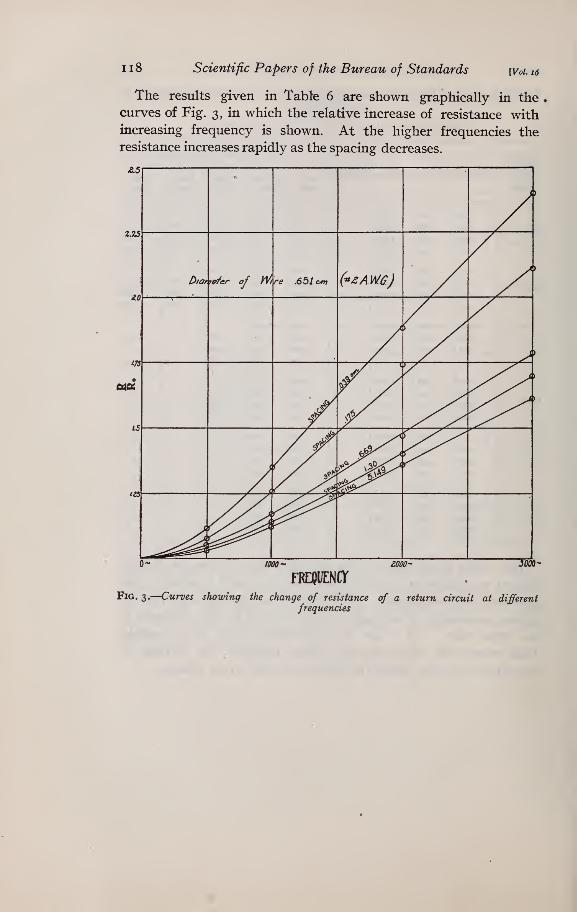
The results given in Tabte 6 are shown graphically in the
curves of Fig. 3, in which the relative increase of resistance withincreasing frequency is shown. At the higher frequencies the
resistance increases rapidly as the spacing decreases.
2.25
aitf
FRDJUENCr
Fig. 3.
—
Curves showing the change of resistance of a return circuit at differentfrequencies
Curtis] A.C. Resistance and Inductance 119
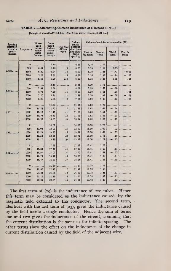
TABLE 7.—^Alternating-Current Inductance of a Return Circuit
[Length of circuit=1716.3 cm. No. 2 Cu. wire. Diam., 0.651 cm]
Spacingbetweenwires incenti-meters
Frequency
Meas- Com-ured putedinduc- induc-tance tancemicro- micro-henrys henrys
Per centdiffer-
ence
Induc-tance;currentdistribu-tion of in-
finite
spacing
Values of each term in equation (79)
First orlog.term
Secondterm
Thirdterm
Fourthterm
0.039.
0.175.
0.67.
1.30.
2.42.
5.15.
500
1000
2000
3000
500
1000
2000
3000
500
1000
2000
3000
500
1000
2000
3000
500
1000
2000
3000
500
1000
2000
3000
6.64
6.30
5.73
5.18
7.99
7.71
7.20
6.86
11.24
11.10
10.79
10.52
13.90
13.78
13.58
13.27
17.03
16.94
16.70
16.47
21.42
21.33
21.12
20.89
6.88
6.70
6.34
5.71
5.29
8.11
7.98
7.70
7.21
6.86
11.34
11.27
11.11
10.81
10.55
14.02
13.97
13.85
13.61
13.39
17.13
17.10
17.00
16.79
16.59
21.50
21.47
21.38
21.19
20.99
.9
.6
.3
2.0
6.88
6.85
6.77
6.58
6.39
8.11
8.08
8.00
7.81
7.62
11.34
11.31
11.22
11.03
10.84
14.02
13.99
13.91
13.72
13.53
17.13
17.10
17.00
16.83
16.64
21.50
21.47
21.39
21.20
21.01
5.16
5.16
5.16
5.16
5.16
6.39
6.39
6.39
6.39
6.39
9.62
9.62
9.62
9.62
9.62
12.30
12.30
12.30
12.30
12.30
15.41
15.41
15.41
15.41
15.41
19.78
19.78
19.78
19.78
19.78
1.72
1.69
1.61
1.42
1.23
1.72
1.69
1.61
1.42
1.23
1.72
1.69
1.61
1.42
1.23
1.72
1.69
1.61
1.42
1.23
1.72
1.69
1.61
1.42
1.23
1.72
1.69
1.61
1.42
1.23
-0.15
- .41
- .84
-1.05
-0.02
- .03
- .05
.01
.01
.02
The first term of (79) is the inductance of two tubes. Hence
this term may be considered as the inductance caused by the
magnetic field external to the conductor. The second term,
identical with the last term of (23), gives the inductance caused
by the field inside a single conductor. Hence the sum of terms
one and two gives the inductance of the circuit, assuming that
the current distribution is the same as for infinite spacing. Theother terms show the effect on the inductance of the change in
current distribution caused by the field of the adjacent wire.
I20 Scientific Papers of the Bureau of Standards [Vol. i6
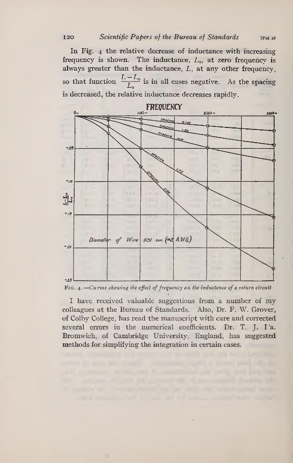
In Fig. 4 the relative decrease of inductance with increasing
frequency is shown. The inductance, Lq, at zero frequency is
always greater than the inductance, L, at any other frequency,
so that function —j
—- is in all cases negative. As the spacing
is decreased, the relative inductance decreases rapidly.
FREQUENCY2000- 3W»-
-.25
Fig. 4.—Curves showing the effect of frequency on the inductance of a return circuit
I have received valuable suggestions from a number of mycolleagues at the Bureau of Standards. Also, Dr. F. W. Grover,
of Colby College, has read the manuscript with care and corrected
several errors in the numerical coefficients. Dr. T. J. I 'a.
Bromwich, of Cambridge University, England, has suggested
methods for simplifying the integration in certain cases.
Curtis] A. C. Resistance and Inductance 121
VI. APPENDIX.—EVALUATION OF INTEGRALS AND DEVEL-OPMENT OF SERIES
In this appendix are given the evaluation of some of the integrals and the expan-sion of some of the series which are necessary for the development of the formulas
of this paper. In each case the nomenclature is that used in the body of the paper.
Only those formulas which are not readily found in text-books of mathematics are
included.1. TO EXPAND LOG q IN A FOURIER SERIES
The quantity q is one side of a triangle of which the other twosides are p and s, having an included angle of 6. Hence
^2 ^ ^2 ^ p2 _ 2 j-p COS 9
Expressing cos B in terms of exponentials
q^ = s^ + 72-7U +e)J
p i9
I €S
Taking the logarithm of both sides of this equation
logg^=log.^+log[i-^J + log i-^]Expanding the last two terms and taking their sum
2logg==log.^-[^(^6^^+6-^^ + ^,(e-^ + 6--^^^ •.
= 2 log S c cos I
2S'cos 20 +~ cos ^.6 +
log q = log s— cos ^ — 7—3 cos 2O
= log^— i-r-j cos r9
3^'cos 3^
]
2. TO DEVELOP^^^ IN A FOURIER SERIES OF
Since
and
it follows that cos a+i sino; =
q cos a=s — p cos 6
q sin a=p sin 6
s — p cos 6 + ip sin 6 s — pe
and q^ = s^+p^-sp[€ +e )
But cos na + i sin na = (cos a-{-i sin a) ""
cos noi+t sm na s — pe
s^ +p^ - spn
/ id -idx
U +e )
i9\n
'K' -^)

122 Scientific Papers of the Bureau of Standards Woi.16
expanding by the binomial theorem and taking the real part
1 'i^oL _ircos na iV no cos B .n{n + i) p^
1^ cos 2d
S 2 S^
nin -^ 1) (n -^ 2) p^ « H^-^T ^^cos3^+...-
J
3. EVALUATION OF THE INTEGRAL h
The integral I^ is given by the following equation where m and n
are integers.
/i=I
pic?pi r"pi"^log[p2+pi2-2ppi cos (^-6'i)]lcosw6'i(i^i
As shown above, the logarithm term may be expanded as
follows:
log [p2 + Pi'- 2ppi cos {e-e^]
^ / \r= 2logp-2S j(-) COS r {B-By) if p> p^
= 2 logpi-2S -i/-Y cosr (^-^1) if p^>p
When this is substituted in I^, there result two types of integrals
to be evaluated. The first gives the following values
:
X27r 2 log p cos n^i dB^ = o when n > o
= 4 TT log p when n =
The second type of integral, viz:
j
" - 2 S i /"^'Y cos r {B- B,) cos ^^, cf(9i
may be integrated term by term as follows:
jcos r (B — B^) cos nB^ dB^
= 1/2 11 cos[r (6'-^i)+n^i]+cos [r {B -B^) -nB,]\ dB^
= when r^^n
== IT cos nB when r = n
CurIts] A. C. Resistance and Inductance 123
Dividing the integration with respect to p^, in the original
integral, into two parts, viz, from to p and from p to a:
7i= \'Px"^^' dp, j^L log p-2X^{^j cos r (d-dM cos nd, dS,
+1
Pi'^'^'^dpA \2logp,-2^U^ COSY {e-e^lcosne^dd^
27rcosn0r pPi^+°+% C^ a. 7 1 1= M pn ^Pi+ I p'^Px^^-'^^'dpA whenn>o
= 47r I pi°^+^ log p c?pi+ I pi°^+^ log pi Jpi when n = o
All of these are readily evaluated.
Below are given the values of /j under all the conditions which
may arise
:
When n>o and n — ni^2.
J _ 27r cos nO r ^^J 1 i \ p^a^-^+' 1^ n |_^ \m — n + 2 m+n + 2/ m — n + 2j
r 2p"^+2 p^a°*-^+2-1
= 27rCOSn^ 7 ; rz -0 — 7 ,x—
l_{m -{- 2y — n^ {m—n-{-2)nj
When n>o and n —m = 2.
when n = o
2irp^ cos ndV^ , I 1A = |_log p - log a -
-J
^^ m + 2 (m + 2)2
The integral /a is given by the following equation where g > P2
-^2= I P2dp2 I ^og ^'+p%-2gp2 cos {a -62) L" cos nd^dd^
Applying the same methods as under I,
h= I P2°''^'<^P2 -—(") cos nee,when n>o
=I
p2°^+'c^p2(4 TT log ^), when n = o
1 24 Scientific Papers of the Bureau of Standards [Voi. zdl
cos naSubstituting the values of—-— and of log q as given above
:
I =--
+ "(" + 'j,("+ ^)0Jcos3g+--..}]
^rr; .rz+>)cos.+^^(^(£Ycos..+. .1n{m+n + 2)s^\_ \s / 2\ \s / J
when n > o
72 = 47r 1P2°^+^^P2J
log^-^cos^-£3COS2 ^-^30033 (9-• •
-J
=; log ^— - COS 6 ;COS 2d 1 COS 3 ^ - • • •
•
m + 2\__ ^ s 2s^ 3^^ J
when n = o.
Washington, March 20, 191 9.