an introduction to hvac systems (live webinar) · refrigerating and air conditioning engineers...
TRANSCRIPT

PDHonline Course M358W (4 PDH)
2012
Instructor: J. Paul Guyer, P.E., R.A., Fellow ASCE, Fellow AEI
PDH Online | PDH Center5272 Meadow Estates Drive
Fairfax, VA 22030-6658Phone & Fax: 703-988-0088
www.PDHonline.orgwww.PDHcenter.com
An Approved Continuing Education Provider
An Introduction to HVAC Systems (Live Webinar)

www.PDHonline.org www.PDHonline.com
PDHonline Webinar M358W © J. Paul Guyer, PE, RA Page 1
AN INTRODUCTION TO HVAC SYSTEMS
Paul Guyer, P.E., R.A.
1© J. Paul Guyer 2010
J. PAUL GUYER, P.E., R.A.
Paul Guyer is a registered Mechanical Engineer, CivilEngineer, Fire Protection Engineer and Architect with 35years building and infrastructure design experience.For an additional nine years he was a principal advisorto the California Legislature on capital outlay andto the California Legislature on capital outlay andinfrastructure issues. He is a graduate of StanfordUniversity and has held a number of national, state andlocal positions with the American Society of CivilEngineers, National Society of Professional Engineers,and the National Council of Engineering Examiners.
2© J. Paul Guyer 2010
1. INTRODUCTION
2. LOAD CALCULATIONS
3. AIR CONDITIONING EQUIPMENT
4. AIR DISTRIBUTION
This is what we will discuss….
5. RULES OF THUMB
6. HEATING AND COOLING MEDIA DISTRIBUTION
3© J. Paul Guyer 2010
1. INTRODUCTION
This is an introduction to air conditioning systems (frequently referred to as HVAC systems – heating, ventilating and air conditioning systems). It is intended for those engineers, architects and construction professionals who are only peripherally involved with HVAC systems in their professional activities….but would like to learn more about HVAC concepts, principles, systems and equipment. It is not a design manual, butsystems and equipment. It is not a design manual, but will give design and construction professionals a step forward in understanding this area of building technology. Design information presented here is presented in a “manual” form, that is, calculations are presented as if calculated manually, although, of course, this is done in most cases in practice by computer programs. This manual presentation will give a better understanding of the underlying principles rather than just leaving the matter of load calculations as a simple data input exercise.
4© J. Paul Guyer 2010
2. LOAD CALCULATIONS
2.1 General. The first step in HVAC system design is to select indoor and outdoor summer and winter design conditions. There are various sources for this information, but among the best are DOD Military Handbook MIL-HDBK-1190 and Naval Facilities Engineering Command NAVFAC Publication P-89, Engineering Weather Data Manual procedures provided below for determining heating and cooling loads are for illustration and training purposes only, but may be used for small systems (e.g., heating systems less than 200,000 Btu per hour and cooling systems less than 10 tons). Computer programs are available that will provide more precise load determinations and the time of day with the highest cooling load. The highest heating load is assumed to occur just before dawn; therefore, this should be considered in the design heating load.
5© J. Paul Guyer 2010
2.2 Heating Load. Heating load…. the amount of heating that must be provided given the assumed outside air temperature and desired inside air temperature….is calculated as described below. Heating load is due to transmission, infiltration and ventilation.
LOAD CALCULATIONS
6© J. Paul Guyer 2010
www.PDHonline.org www.PDHonline.com
PDHonline Webinar M358W © J. Paul Guyer, PE, RA Page 2
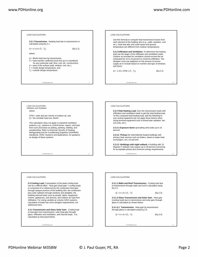
2.2.1 Transmission. Heating load due to transmission is calculated using Eq 2.1.
Q = U x A x (Ti - To) (Eq 2.1)
where:
LOAD CALCULATIONS
Q = Btu/hr heat loss by transmission,U = heat transfer coefficient (look this up in a handbook
for your particular wall, floor, roof, etc. construction)A = area of the surface (wall, window, roof, etc.),Ti = inside design temperature, andTo = outside design temperature.
7© J. Paul Guyer 2010
Use this formula to compute heat transmission losses from each element of the building skin (e.g., walls, windows, roof, etc.). Note that attic and crawl space and ground temperature are different from outdoor temperatures.
2.2.2 Infiltration and Ventilation. To determine the heating load use the larger of the infiltration and ventilation loads. Outdoor air provided for ventilation should exceed the air
LOAD CALCULATIONS
pexhausted by 10 to 15 percent to minimize infiltration. The designer must use judgment on the amount of excess supply air to include based on number and type of windows and doors.
Q = 1.10 x CFM x (Ti - To) (Eq 2.2)
8© J. Paul Guyer 2010
where:
CFM = cubic feet per minute of outdoor air, andQ = the sensible heat loss, Btu/hr.
This calculation does not apply to industrial ventilation systems, e.g., systems to control fumes, vapors, and dust from such processes as plating, painting, welding, and
LOAD CALCULATIONSInfiltration and Ventilation
p p g, p g, g,woodworking. Refer to American Society of Heating, Refrigerating and Air Conditioning Engineers (ASHRAE) Handbook, HVAC Systems and Applications, for guidance on design of these systems.
9© J. Paul Guyer 2010
2.2.3 Total Heating Load. Sum the transmission loads with infiltration and ventilation loads to get the total heating load. To this computed total heating load, add the following to size central equipment (do not apply these factors when sizing terminal equipment such a finned-tube radiation, fan-coil units, etc.):
2.2.3.1 Exposure factor (prevailing wind side) up to 15
LOAD CALCULATIONS
p (p g ) ppercent.
2.2.3.2 Pickup (for intermittently heated buildings with primary heat sources such as boilers, steam-to-water heat exchangers, etc.) 10 percent.
2.2.3.3 Buildings with night setback. A building with 10 degrees F setback may require up to 30 percent oversizing for acceptable pickup and minimum energy requirements.
10© J. Paul Guyer 2010
2.3 Cooling Load. Computation of the peak cooling load can be a difficult effort. Heat gain (heat gain = cooling load) is composed of or influenced by the conduction heat gain through opaque portions of the building skin; the conduction plus solar radiation through windows and skylights; the building internal loads such as people, lights, equipment, motors, appliances, and devices; and outdoor air load from i filt ti F i i i bl i l (VAV) t
LOAD CALCULATIONS
infiltration. For sizing variable air volume (VAV) systems, calculation of loads has more stringent requirements, not addressed here.
2.3.1 Transmission and Glass Solar Gain. Cooling load is heat gain from transmission, solar heat gain through glass, infiltration and ventilation, and internal loads. It is calculated as discussed below.
11© J. Paul Guyer 2010
2.3.1.1 Walls and Roof Transmission. Cooling load due to transmission through walls and roof is calculated using Eq 2.3.
Q = U x A x (To - Ti) (Eq 2.3)
2.3.1.2 Glass Transmission and Solar Gain. Heat gain ( li l d) d t t i i d l i th h
LOAD CALCULATIONS
(cooling load) due to transmission and solar gain through glass is calculated as shown below.
2.3.1.2.1 Transmission. Heat gain by transmission through glass is calculated using Eq 2.4.
Q = U x A x (To - Ti) (Eq 2.4)
12© J. Paul Guyer 2010

www.PDHonline.org www.PDHonline.com
PDHonline Webinar M358W © J. Paul Guyer, PE, RA Page 3
2.3.1.2.2 Solar Heat Gain. Solar heat gain through glass is calculated using (Eq 2.5).
Q = A x SC x SHGF (Eq 2.5)
where:
SC h di ffi i t d
LOAD CALCULATIONS
SC = shading coefficient, and
SHGF = solar heat gain factor (look up the SHGF in a handbook (e.g., ASHRAE Handbook, Fundamentals) for each exposure and type of glass).
13© J. Paul Guyer 2010
2.3.2 Infiltration and Ventilation. Sensible and latent heat gains from infiltration and ventilation are calculated using Eqs 2.6 and 2.7. The concepts of sensible and latent heat require an understanding of psychometrics, which is beyond the scope of this discussion. The question of latent heat usually comes into play only in particularly humid climates. In this i lifi d t ti ill M dit
LOAD CALCULATIONS
simplified presentation we will assume a Mediterranean climate (i.e. like California) and generally not be concerned with latent heat.
14© J. Paul Guyer 2010
2.3.2.1 Sensible
QS = 1.10 x CFM x (To - Ti) (Eq 2.6)
2.3.2.2 Latent
QL = 4840 x CFM x W (Eq 2.7)
LOAD CALCULATIONSInfiltration and Ventilation
where:
W = change in humidity ratio (lb water/lb air).
15© J. Paul Guyer 2010
2.3.2.3 Ventilation Rates. Refer to ASHRAE Standard 62 for ventilation requirements or the typical values below:
Auditoriums, theaters - 15 cfm/personSleeping rooms - 15 cfm/personBedroom - 30 cfm/roomClassroom - 15 cfm/personCommunication centers - 20 cfm/person
LOAD CALCULATIONSInfiltration and Ventilation
Communication centers - 20 cfm/personConference rooms - 20 cfm/personCorridors - 0.1 cfm/sq ftDining - 20 cfm/personLobbies - 15 cfm/personLocker, dressing rooms - 0.5 cfm/sq ftLounges, bars - 30 cfm/personOffices - 20 cfm/personToilet, bath (private) - 35 cfm/roomToilet (public) - 50 cfm/water closet or urinal
16© J. Paul Guyer 2010
The total corrected outdoor air requirement for central systems supplying spaces with different ratios of outdoor-air-to-supply-air is determined from the following:
CFMot = Y x CFMst (Eq 2.8)
LOAD CALCULATIONSInfiltration and Ventilation
where:
CFMot = corrected total outdoor air quantity,CFMst = total system airflow (i.e., sum of air supplied to all spaces), andY = corrected fraction of outdoor air, or
Y = X/(1 + X - Z) (Eq 2.9)
17© J. Paul Guyer 2010
where:
X = CFMoa/CFMst,Z = CFMoc/CFMsc,
where:
LOAD CALCULATIONSInfiltration and Ventilation
CFMoa = uncorrected sum of outdoor airflow rates for spaces on the system,CFMoc = outdoor air required for critical space, and CFMsc = supply air to the critical space.
The critical space is that space with the greatest required fraction of outdoor air in the supply to that space.
18© J. Paul Guyer 2010

www.PDHonline.org www.PDHonline.com
PDHonline Webinar M358W © J. Paul Guyer, PE, RA Page 4
2.3.3 Internal Loads
2.3.3.1 People Loads. Adjusted (normal male/female/child), per person.
Sensible/LatentOffi ( t d li ht k t i ) 245 Bt /h 255 Bt /h
LOAD CALCULATIONS
Office (seated light work, typing) 245 Btu/hr 255 Btu/hrFactory (light bench work) 345 Btu/hr 435 Btu/hrFactory (light machine work) 345 Btu/hr 695 Btu/hrGymnasium athletics 635 Btu/hr 1165 Btu/hr
19© J. Paul Guyer 2010
2.3.3.2 Lights and Equipment
2.3.3.2.1 Lights
Q = 3.41 x W x Ful x Fsa (Eq 2.10)
LOAD CALCULATIONSInternal Loads
where:
W = total light wattage,Ful = use factor, andFsa = special allowance factor for fluorescent fixtures or for fixtures that release only part of their heat to the conditioned space.
20© J. Paul Guyer 2010
2.3.3.2.2 Equipment
(1)Motors within conditioned space or within airstream.
Q = 2545 x HP/(Em x Flm x Fum) (Eq 2.11)
where:
LOAD CALCULATIONSInternal Loads
HP = motor horsepower,Em = motor efficiency,Flm = motor load factor, andFum = motor use factor.
21© J. Paul Guyer 2010
(2) Appliances and equipment, such as business machines and computers. Refer to ASHRAE Handbook, Fundamentals and manufacturer’s data to determine sensible and latent heat gains from equipment.
Qs = 3.41 x W x Fue (Eq 2.12)
LOAD CALCULATIONSInternal Loads
where:
Qs = sensible load,W = appliance wattage, andFue = equipment use factor.
22© J. Paul Guyer 2010
2.3.3.3 Heat Gain From Miscellaneous Sources
2.3.3.3.1 HVAC Fan Motors (Outside the Airstream). Typically, thirty-five percent of the input to an HVAC fan motor is converted to heat in the airstream because of fan inefficiency.
2 3 3 3 2 HVAC F M t (Withi th Ai t ) Th
LOAD CALCULATIONSInternal Loads
2.3.3.3.2 HVAC Fan Motors (Within the Airstream). The motor load is converted to heat.
2.3.3.3.3 Duct Leakage. Loss of supply air due to duct leakage shall be compensated by system capacity as follows:
(1) Well designed and constructed system: increase fan capacity by 3 percent.(2) Poorly designed and constructed system: increase fan capacity by 10 percent.
23© J. Paul Guyer 2010
3. AIR CONDITIONING EQUIPMENT
A detailed discussion of air conditioning equipment is beyond the scope of this presentation, but a few comments can be offered.
24© J. Paul Guyer 2010

www.PDHonline.org www.PDHonline.com
PDHonline Webinar M358W © J. Paul Guyer, PE, RA Page 5
3.1 Cooling Systems
The basis of air cooling systems is the refrigeration cycle.
AIR CONDITIONING EQUIPMENT
25© J. Paul Guyer 2010
AIR CONDITIONING EQUIPMENT
3.1 Cooling and Heating
Furnace orheating coil
© J. Paul Guyer 2010 26
heating coil
3.1.1 Central Air Conditioning Systems. Use these systems for applications where several spaces with uniform loads will be served by a single apparatus and where precision control of the environment is required. Cooling coils can be direct expansion or chilled water. Select air cooled or evaporative condensers, cooling towers, and ground-loop systems based on life cycle economics considering operating
AIR CONDITIONING EQUIPMENTCooling Systems
y y g p gefficiencies and maintenance costs associated with outdoor design conditions and environment, e.g., high ambient temperatures and dusty conditions could adversely impact the operation of air cooled condensers. Consider temperature rise of chilled water supply when selecting chilled water coils, especially for applications requiring precision humidity control.
27© J. Paul Guyer 2010
3.1.2 Unitary Air Conditioning Systems. These systems should generally be limited to loads less than 100 tons. Unitary systems are packaged in self-contained or split configurations. Self-contained units incorporate components for cooling or cooling and heating in one apparatus. Thermostatic expansion valves are preferred over capillary tubes and orifices for refrigerant control when available as a manufacturer's option since expansion valves provide better
AIR CONDITIONING EQUIPMENTCooling Systems
p p psuperheat control over a wide range of operating conditions. Split systems may include the following configurations:
a) Direct expansion coil and supply fan combined with a remote compressor and condensing coil; or
b) Direct expansion coil, supply fan, and compressor combined with a remote condenser, cooling tower, or ground-loop system.
28© J. Paul Guyer 2010
These systems generally have lower first cost than central systems but may have higher life cycle costs. If part load operation is anticipated for a majority of equipment operating life, consider multiple unitary equipment for superior operating efficiencies and added reliability. Refer to ASHRAE
AIR CONDITIONING EQUIPMENTCooling SystemsUnitary Air Conditioning Systems
Handbook, Equipment for size and selection criteria.
29© J. Paul Guyer 2010
3.1.3 Room Air Conditioning Units. These units are self-contained units serving only one space. These units are typically referred to as window or through-the-wall type air conditioners. Rooms served by these units should have a separate HVAC unit to provide ventilation air for a group of rooms. Use them when they are life cycle cost effective.
AIR CONDITIONING EQUIPMENTCooling Systems
Refer to ASHRAE Equipment Handbook.
30© J. Paul Guyer 2010

www.PDHonline.org www.PDHonline.com
PDHonline Webinar M358W © J. Paul Guyer, PE, RA Page 6
3.1.4 Built-up Systems. These systems consist of individual components assembled at the building site. Generally, use them when a large volume of air is handled. These systems may be used as remote air handling systems with a central cooling plant. unitary air handling units. Determine the number of air handling units by an economic division of the
AIR CONDITIONING EQUIPMENTCooling Systems
load, considering: (a) the value of space occupied by equipment; (b) the extent of ductwork and piping; (c) the multiplicity of control, maintenance, and operating points; and (d) energy conservation factors.
31© J. Paul Guyer 2010
3.2 Heating Systems. Heating sources can be either steam, hot water, natural gas, oil, electricity, or a renewable resource. Select these sources based on life cycle cost.Heating systems may be combined with ventilating systems when feasible. Heating-dominated climates require perimeter radiation at windows in office spaces.
AIR CONDITIONING EQUIPMENT
3.2.1 Individual Heating Plants. Locate individual heating plants in the building they serve or in a separate, adjoining building.
3.2.2 Central Heating Plants. Base the total heating system capacity on normal demand rather than total connected load.
32© J. Paul Guyer 2010
3.3 All-Air Systems. Refer to ASHRAE Systems Handbook. In humid climates, provide all-air systems for air conditioning. These systems are central systems which provide complete sensible and latent heating and cooling of the air supply. These systems are either single path or dual path. Single-path systems have heating and cooling elements in a series configuration. Dual path system elements are arranged in
AIR CONDITIONING EQUIPMENT
g p y gparallel. Consolidation of system components at a central location provides increased opportunity for energy conservation.
33© J. Paul Guyer 2010
3.3.1 Constant-Volume Systems. Use where room conditions are to be maintained by supplying a constant volume of air to the space and varying supply air temperature in response to demands for net space heating or cooling.
a) Applications. In addition to multi-zone systems, this includes single-zone or single space applications in auditoriums, meeting rooms, cafeterias, restaurants, and small retail stores.
AIR CONDITIONING EQUIPMENTAll-Air Systems
b) Multi-zone Systems. Use these systems to provide individual temperature control of a small number of zones, maximum 10 zones, from a central air handler. For normal comfort cooling applications, place cooling and heating coils in the air handler. For applications where humidity control is critical, place coils in series so that air is conditioned by the cooling coil prior to passing to the hot deck. Provide cooling by direct-expansion or chilled-water coils. Provide heating by steam coils, hot water coils, or electric coils.
34© J. Paul Guyer 2010
c) Terminal Reheat Systems. These systems overcome zoning limitations by adding individual heating coils in each zone's branch duct to compensate for areas of unequal heating load. Heat, whether in the form of hot water, steam, or electrical resistance heaters, is applied to either preconditioned primary air or recirculated room air.
AIR CONDITIONING EQUIPMENTAll-Air Systems
(1) These systems waste energy because supply air is cooled to a low enough temperature to serve the zone needing the coolest air, but then supply air must be reheated for other zones to avoid overcooling. Where constant volume is maintained, the waste of energy can be even more significant. Reset cold deck temperature to meet cooling requirements of the room with the largest load or to satisfy humidity requirements. This cold deck temperature control reduces energy consumption.
35© J. Paul Guyer 2010
(2) Due to high energy consumption, limit these systems to applications requiring close control of temperature and humidity, such as hospital intensive care areas and laboratories. When economically feasible, use heat recovered from the refrigeration cycle in heating coils.
AIR CONDITIONING EQUIPMENTAll-Air Systems
3.3.2 Variable Air Volume (VAV) Systems. Use VAV systems for buildings with sufficient zones (11 or more zones) and load variation to permit reduction of fan capacity for significant periods during the day. Do not use bypass VAV systems. The complexity of systems should be consistent with minimum requirements to adequately maintain space conditions.
36© J. Paul Guyer 2010

www.PDHonline.org www.PDHonline.com
PDHonline Webinar M358W © J. Paul Guyer, PE, RA Page 7
3.3.3 Economizer Cycle. The economizer cycle should not be used in humid climates and for spaces where humidity control is critical, such as computer rooms. Problems have been experienced with linkage corrosion, excessive damper leakage, jammed linkage on large dampers, and inadequate maintenance. Outdoor air dampers should be located away from the intake louver and after duct transition to minimize
AIR CONDITIONING EQUIPMENT
exposure to weather and size of dampers. Provide outdoor air dry bulb changeover rather than enthalpy or outdoor air/return air comparator changeover. With VAV systems, return or relief fans shall not be used. An economizer should only be used when it can be designed with gravity relief through the building envelope. Size gravity relief dampers to prevent building over pressurization.
37© J. Paul Guyer 2010
3.4 System and Equipment Performance. For size andselection criteria of systems and equipment, refer to ASHRAEEquipment Handbook. HVAC systems shall be able to dehumidify supply air under loading conditions, provide reliable operations, and tolerate reasonable variations in chilled-water temperatures. Air conditioning systems generally operate at part load conditions most of the time. This is
AIR CONDITIONING EQUIPMENT
particularly true of comfort air conditioning systems which often operate at less than 50 percent of their design load capacity for more than 50 percent of the time. Since high part load efficiencies are desirable to conserve energy, the selection of equipment and step starting and sequencing controls shall be made with an emphasis on reducing life-cycle costs at part load conditions. Verify and document the equipment operation in accordance with ASHRAE Guideline 1,Commissioning of HVAC Systems.
38© J. Paul Guyer 2010
4. AIR DISTRIBUTION
4.1 Duct Design for HVAC Systems
4.1.1 Sizing General. ASHRAE Handbook, Fundamentals recognizes three methods of sizing ductwork: the equal friction method, the static regain method, and the T-method. The ASHRAE Handbook also provides a commonly used chart for sizing ducts using the equal friction method. For design of small simple systems, the equal friction method will suffice. Use the static regain method for VAV.
39© J. Paul Guyer 2010
4.1.2 Equal Friction Method Sizing. Select a constant pressure loss in inches of water per 100 foot length of duct from the preferred part of the ASHRAE equal friction sizing chart. The preferred part is between 0.08 and 0.6 inches of water per 100 feet friction loss for air quantities up to 18,000 cfm, and between 1800 fpm and 4000 fpm for air quantities greater than 18,000 cfm. Use low velocities and a low friction
AIR DISTRIBUTION
drop for small projects, or where ductwork is cheap and energy is expensive. For systems of 18,000 cubic feet per minute and over, use a friction loss of 0.08 and velocities of 1800 to 3000 feet per minute. After sizing the entire system at the selected unit pressure drop, go back and adjust velocities and pressure drops in the shorter branches to equalize the pressure drops at each duct branch junction.
40© J. Paul Guyer 2010
4.1.3 Ductwork, General
4.1.3.1 Round Ducts. Use round ducts wherever possible. Under normal applications, the minimum duct size shall be 4 inches in diameter. Use smooth curved elbows as much as possible. If these are not available, use three-piece elbows for velocities below 1600 feet per minute and five-piece elbows for
l iti b 1600 f t i t Th th t di h ll
AIR DISTRIBUTION
velocities above 1600 feet per minute. The throat radius shall not be less than 0.75 times the duct diameter.
4.1.3.2 Rectangular Ducts. Use a minimum duct size of 6 inches by 6 inches. Where possible, keep one dimension constant in transitions and do not make transitions in elbows. Make transitions in sides and bottom of the duct keeping top level to maintain maximum clearance above ceiling.
41© J. Paul Guyer 2010
AIR DISTRIBUTION
4.1.3 Ductulator
© J. Paul Guyer 2010 42
www.PDHonline.org www.PDHonline.com
PDHonline Webinar M358W © J. Paul Guyer, PE, RA Page 8
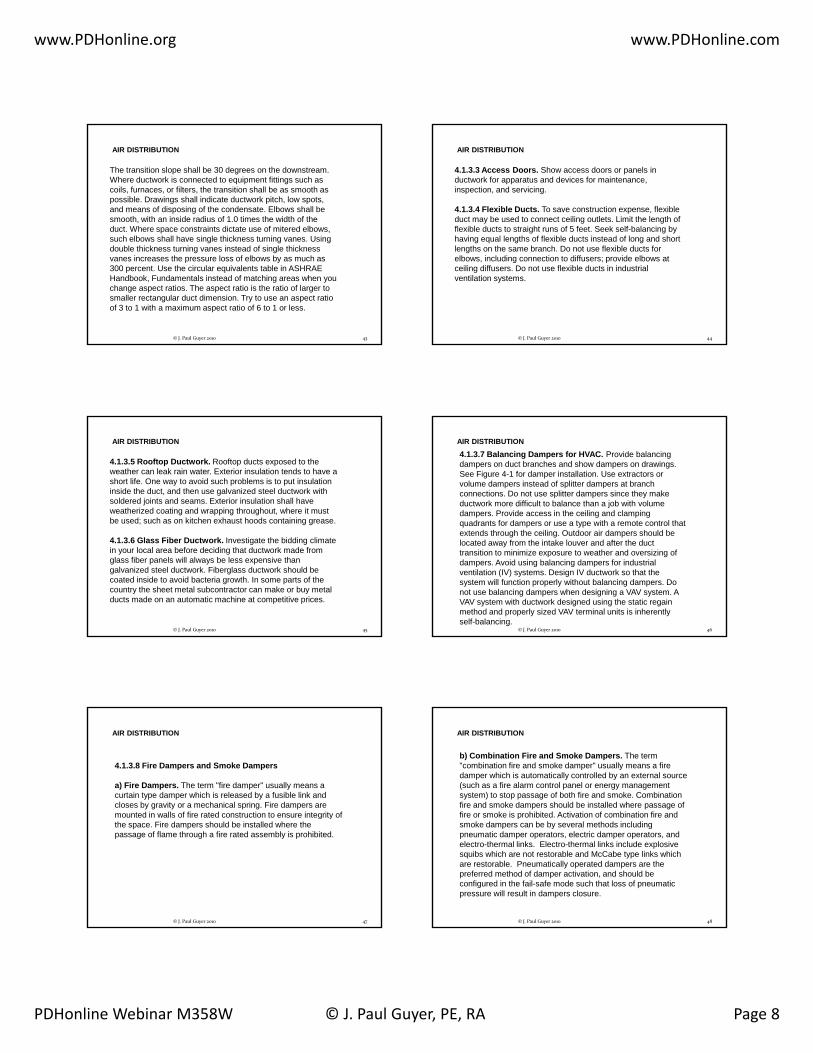
The transition slope shall be 30 degrees on the downstream. Where ductwork is connected to equipment fittings such as coils, furnaces, or filters, the transition shall be as smooth as possible. Drawings shall indicate ductwork pitch, low spots, and means of disposing of the condensate. Elbows shall be smooth, with an inside radius of 1.0 times the width of the duct. Where space constraints dictate use of mitered elbows,
AIR DISTRIBUTION
such elbows shall have single thickness turning vanes. Using double thickness turning vanes instead of single thickness vanes increases the pressure loss of elbows by as much as 300 percent. Use the circular equivalents table in ASHRAE Handbook, Fundamentals instead of matching areas when you change aspect ratios. The aspect ratio is the ratio of larger to smaller rectangular duct dimension. Try to use an aspect ratio of 3 to 1 with a maximum aspect ratio of 6 to 1 or less.
43© J. Paul Guyer 2010
4.1.3.3 Access Doors. Show access doors or panels in ductwork for apparatus and devices for maintenance, inspection, and servicing.
4.1.3.4 Flexible Ducts. To save construction expense, flexible duct may be used to connect ceiling outlets. Limit the length of flexible ducts to straight runs of 5 feet. Seek self-balancing by
AIR DISTRIBUTION
having equal lengths of flexible ducts instead of long and short lengths on the same branch. Do not use flexible ducts for elbows, including connection to diffusers; provide elbows at ceiling diffusers. Do not use flexible ducts in industrial ventilation systems.
44© J. Paul Guyer 2010
4.1.3.5 Rooftop Ductwork. Rooftop ducts exposed to the weather can leak rain water. Exterior insulation tends to have a short life. One way to avoid such problems is to put insulation inside the duct, and then use galvanized steel ductwork with soldered joints and seams. Exterior insulation shall have weatherized coating and wrapping throughout, where it must be used; such as on kitchen exhaust hoods containing grease.
AIR DISTRIBUTION
4.1.3.6 Glass Fiber Ductwork. Investigate the bidding climate in your local area before deciding that ductwork made from glass fiber panels will always be less expensive than galvanized steel ductwork. Fiberglass ductwork should be coated inside to avoid bacteria growth. In some parts of the country the sheet metal subcontractor can make or buy metal ducts made on an automatic machine at competitive prices.
45© J. Paul Guyer 2010
4.1.3.7 Balancing Dampers for HVAC. Provide balancing dampers on duct branches and show dampers on drawings. See Figure 4-1 for damper installation. Use extractors or volume dampers instead of splitter dampers at branch connections. Do not use splitter dampers since they make ductwork more difficult to balance than a job with volume dampers. Provide access in the ceiling and clamping quadrants for dampers or use a type with a remote control that
AIR DISTRIBUTION
q p ypextends through the ceiling. Outdoor air dampers should be located away from the intake louver and after the duct transition to minimize exposure to weather and oversizing of dampers. Avoid using balancing dampers for industrial ventilation (IV) systems. Design IV ductwork so that the system will function properly without balancing dampers. Do not use balancing dampers when designing a VAV system. A VAV system with ductwork designed using the static regain method and properly sized VAV terminal units is inherently self-balancing.
46© J. Paul Guyer 2010
4.1.3.8 Fire Dampers and Smoke Dampers
a) Fire Dampers. The term "fire damper" usually means a curtain type damper which is released by a fusible link and closes by gravity or a mechanical spring. Fire dampers are mounted in walls of fire rated construction to ensure integrity of
AIR DISTRIBUTION
g ythe space. Fire dampers should be installed where the passage of flame through a fire rated assembly is prohibited.
47© J. Paul Guyer 2010
b) Combination Fire and Smoke Dampers. The term "combination fire and smoke damper" usually means a fire damper which is automatically controlled by an external source (such as a fire alarm control panel or energy management system) to stop passage of both fire and smoke. Combination fire and smoke dampers should be installed where passage of fire or smoke is prohibited. Activation of combination fire and
AIR DISTRIBUTION
psmoke dampers can be by several methods including pneumatic damper operators, electric damper operators, and electro-thermal links. Electro-thermal links include explosive squibs which are not restorable and McCabe type links which are restorable. Pneumatically operated dampers are the preferred method of damper activation, and should be configured in the fail-safe mode such that loss of pneumatic pressure will result in dampers closure.
48© J. Paul Guyer 2010

www.PDHonline.org www.PDHonline.com
PDHonline Webinar M358W © J. Paul Guyer, PE, RA Page 9
In electronic data processing rooms, combination fire and smoke dampers should be installed in walls with a fire resistance rating of 1 hour or greater. In other type spaces, either fire dampers or combination fire and smoke dampers should be installed in walls with a fire resistance rating of 2 hours or greater. Where a smoke damper is required to stop passage of smoke through a barrier (e.g., hospitals), the i t ll ti f bi ti fi d k d i
AIR DISTRIBUTION
installation of a combination fire and smoke damper is required.
c) Mounting Details. Fire dampers and combination fire and smoke dampers must remain in the wall during a fire. Though ductwork may collapse, the damper should remain in the fire rated assembly, therefore, indicate on drawings the details for attaching dampers to the wall. Use UL listed firestopping materials between the damper collar and the wall, floor, or ceiling assembly where penetrated.
49© J. Paul Guyer 2010
AIR DISTRIBUTION
50© J. Paul Guyer 2010
Figure 4-1
4.1.3.9 Fan System Effect Factors. Fans are tested and rated based upon a certain standard ductwork arrangement. If installed ductwork creates adverse flow conditions at the fan inlet or fan outlet, loss of fan performance is defined as a system effect factor. The system effect factor can be caused by obstructions or configurations near the fan inlet and outlet. For example, failure to recognize the affect on performance of
i l t th f i l t ill h d ff t t
AIR DISTRIBUTION
swirl at the fan inlet will have an adverse effect on system performance. Refer to Air Movement and Control Association (AMCA) 201, Fans and Systems for additional information on fans and system effects.
4.1.4 Ductwork Details
4.1.4.1 Branches. See Figure 4-2 and Figure 4-3.4.1.4.2 Elbows. See Figure 4-4.4.1.4.3 Offsets and Transitions. See Figure 4-5.
51© J. Paul Guyer 2010
AIR DISTRIBUTION
© J. Paul Guyer 2010 52
Figure 4-2
AIR DISTRIBUTION
© J. Paul Guyer 2010 53
Figure 4-3
AIR DISTRIBUTION
© J. Paul Guyer 2010 54
Figure 4-4

www.PDHonline.org www.PDHonline.com
PDHonline Webinar M358W © J. Paul Guyer, PE, RA Page 10
AIR DISTRIBUTION
© J. Paul Guyer 2010 55
Figure 4-5
5. RULES OF THUMB
5.1 General. The following information provides guidance that could be used in planning to estimate utility requirements and to assess the adequacy of equipment sizing during design reviews. Note that it is preferable to do a quick block load calculation instead of using these rules of thumb.
5.2 Air Conditioning Capacity. See Table 5-1.
© J. Paul Guyer 2010 56
5.2 Air Conditioning Capacity. See Table 5 1.
5.3 Heating Capacity. 35 to 40 Btu per square foot for mild climate region (less than 4,000 degree days), no fresh air load.
5.4 Chilled Water Circulation. 2.5 to 3.0 gallons per minute per ton.
5.5 Hot WaterGallons per minute (20 degree drop) = Btu/h/10,000
Gallon per minute = (Btu/h)/(500 x TD) (temperature drop)
5.6 Condenser Water. Required thermal capacity of cooling t 15 000 Bt /h t 3 t
RULES OF THUMB
© J. Paul Guyer 2010 57
water = 15,000 Btu/h per ton, or = 3 gpm per ton
5.7 Steam. 1 pound of steam per 1,000 Btu.
5.8 Condensate. 120 gallons per 1,000 pounds steam.
RULES OF THUMB
© J. Paul Guyer 2010 58
Table 5-1
This discussion provides criteria and guidance for the design and construction of heating and cooling distribution systems outside of buildings. The mediums used in these distribution systems include:
6. HEATING AND COOLING MEDIA DISTRIBUTION
• High temperature hot water (HTHW) (251 deg. F to 450 deg. F)
• Low temperature hot water (LTHW) (150 deg. F to 250 deg. F)
• Low pressure steam systems (up to 15 psig)
• High pressure steam systems (over 15 psig)
• Condensate return systems (up to 200 deg. F)
• Chilled water systems
59© J. Paul Guyer 2010
6.1 Distribution Media Selection
6.1.1 Connecting to an existing system. Almost all heating and cooling distribution systems will be connected to an existing central distribution system. In this case, the designer most often designs for the media to which it is being connected-HTHW, LTHW,
HEATING AND COOLING MEDIA DISTRIBUTION
steam/condensate, or chilled water.
60© J. Paul Guyer 2010

www.PDHonline.org www.PDHonline.com
PDHonline Webinar M358W © J. Paul Guyer, PE, RA Page 11
6.1.2 Installation of new system. When no existing system is present, the designer must select the system that is most appropriate for the end user. High temperature hot water and steam/condensate systems are the most common types of distribution systems currently used on many installations. H t h ld l th t t d
HEATING AND COOLING MEDIA DISTRIBUTIONDistribution Media Selection
However, a new system should only use the temperatures and pressures necessary to meet the requirements of the installation. For example, the use of high pressure steam sterilizers or steam kettles at several facilities may require the use of a high pressure steam or HTHW system.
61© J. Paul Guyer 2010
However, it is usually much more cost effective (on a first cost and life cycle cost basis) to use a low or medium temperature hot water distribution systems whenever possible and to incorporate stand alone high pressure/temperature systems where required. The lower maintenance costs, safer operation, longer life of systems, and simpler system controls
HEATING AND COOLING MEDIA DISTRIBUTIONDistribution Media Selection
for hot water systems often offset the costs of larger piping required. For further assistance for selecting the system type, refer to ASHRAE Handbook, "HVAC Systems and Equipment.”
62© J. Paul Guyer 2010
6.2 System Types. When selecting a distribution system, the designer must determine which system types apply to a particular medium. The designer must also exclude systems which are not appropriate for a particular site or for which the customer has no interest. Examples of this are locating aboveground systems in non-industrial areas where the
HEATING AND COOLING MEDIA DISTRIBUTION
g yinstallation is sensitive to the aesthetic appearance of the area or routing concrete shallow trench systems through drainage swales or flood plains.
63© J. Paul Guyer 2010
6.2.1 Heat Distribution Systems in Concrete Trenches. This system is a buried system with its removable concrete cover installed at grade and will typically be used for HTHW and steam/condensate systems. In rare instances, it may also be used for chilled water and LTHW in the event no plastic piping is installed in the same trench as high temperature (greater than 250 degrees
HEATING AND COOLING MEDIA DISTRIBUTIONSystem Types
F) piping systems. Experience has shown that if insulation of a high temperature system is compromised, temperatures can increase to such a level and cause damage to the plastic piping.
64© J. Paul Guyer 2010
HEATING AND COOLING MEDIA DISTRIBUTIONSystem Types
Figure 6-1
65© J. Paul Guyer 2010
HEATING AND COOLING MEDIA DISTRIBUTIONSystem Types
Figure 6-2
66© J. Paul Guyer 2010

www.PDHonline.org www.PDHonline.com
PDHonline Webinar M358W © J. Paul Guyer, PE, RA Page 12
HEATING AND COOLING MEDIA DISTRIBUTIONSystem Types
Figure 6-3
67© J. Paul Guyer 2010
HEATING AND COOLING MEDIA DISTRIBUTIONSystem Types
Figure 6-4Free Pipe Supports
68© J. Paul Guyer 2010
HEATING AND COOLING MEDIA DISTRIBUTIONSystem Types
Figure 6-5Guided Pipe Supports
69© J. Paul Guyer 2010
HEATING AND COOLING MEDIA DISTRIBUTIONSystem Types
Figure 6-6Pipe Anchors
70© J. Paul Guyer 2010
HEATING AND COOLING MEDIA DISTRIBUTIONSystem Types
Figure 6-7Pipe Expansion Couplings
71© J. Paul Guyer 2010
HEATING AND COOLING MEDIA DISTRIBUTIONSystem Types
Figure 6-8Pipe Expansion Couplings
72© J. Paul Guyer 2010

www.PDHonline.org www.PDHonline.com
PDHonline Webinar M358W © J. Paul Guyer, PE, RA Page 13
6.2.2 Pre-engineered Underground Heat Distribution Systems. This system is designed for higher pressure and temperature applications. The two types of pre-engineered systems are the drainable-dryable-testable (DDT) type which is used for high pressure steam/condensate and HTHW at all sites, and high temperature hot water at any type of site, and the water spread li iti (WSL) t hi h i d l f t / d t t
HEATING AND COOLING MEDIA DISTRIBUTIONSystem Types
limiting (WSL) type which is used only for steam/condensate systems in bad and moderate sites. HTHW supply and return lines may be provided in a single casing; however, steam and condensate lines must always be provided in separate casings because condensate lines typically last less than half as long as the steam line and are easier to replace when in a separate casing.
73© J. Paul Guyer 2010
HEATING AND COOLING MEDIA DISTRIBUTIONSystem Types
Figure 6-9Pre-engineered Systems
74© J. Paul Guyer 2010
HEATING AND COOLING MEDIA DISTRIBUTIONSystem Types
Figure 6-10Pre-engineered Systems
75© J. Paul Guyer 2010
6.2.3 Prefabricated Underground Heating/Cooling Distribution System. This system is designed for lower temperature and pressure applications. It is typically used for
HEATING AND COOLING MEDIA DISTRIBUTIONSystem Types
LTHW, chilled water, or combination LTHW/chilled water systems. These systems have features similar to the other distribution systems described; it is distinguished by the fact components are largely prefabricated rather than field-fabricated.
76© J. Paul Guyer 2010
6.2.4 Aboveground Heat Distribution System. This system may be used for HTHW, steam/condensate, and LTHW systems, and for chilled water systems where freezing is not a concern.
HEATING AND COOLING MEDIA DISTRIBUTIONSystem Types
77© J. Paul Guyer 2010
HEATING AND COOLING MEDIA DISTRIBUTIONSystem Types
Figure 6-11Pre-engineered/Above Ground Systems
78© J. Paul Guyer 2010

www.PDHonline.org www.PDHonline.com
PDHonline Webinar M358W © J. Paul Guyer, PE, RA Page 14
6.3 System Selection
The system type selected will be based on the type of media that is distributed.
HEATING AND COOLING MEDIA DISTRIBUTION
79© J. Paul Guyer 2010
6.3.1 High Temperature Water and Steam/condensate Systems. The order of preference for system types for high temperature and high pressure systems are:
• Aboveground Heat Distribution System. This is the least expensive system and historically requires the lowest maintenance and operating costs. However, the safety and aesthetics of an aboveground system are not always desirable and must be
HEATING AND COOLING MEDIA DISTRIBUTIONSystem Selection
g y yaccepted by the end user.
• Heat Distribution Systems in Concrete Trenches. This is the most dependable of the buried distribution systems. The piping is totally accessible through removable concrete covers, the piping does not come in contact with the soil, and ground water is drained away from the piping system to low point drains. Except in rare instances, this is the system that should be selected if aboveground is not acceptable with the end user. trench system.
80© J. Paul Guyer 2010
• Pre-engineered Underground Heat Distribution System. This type of buried distribution system should be selected as the last option due to very short system lives which are typically caused by poor drainage, poor corrosion protection, and improper installation. Instances where it would be used would be when aboveground is not acceptable with the end user or
HEATING AND COOLING MEDIA DISTRIBUTIONSystem SelectionHigh Temperature Water and Steam/condensate Systems
be when aboveground is not acceptable with the end user or when drainage swales and high ground water prevent the installation of a concrete trench system.
81© J. Paul Guyer 2010
6.3.2 Low Temperature and Chilled Water Systems. The order of preference for system types for hot water, chilled water or combination hot/chilled water are:
• Aboveground Heat Distribution System. This is the least expensive system and historically requires the lowest
HEATING AND COOLING MEDIA DISTRIBUTIONSystem Selection
expensive system and historically requires the lowest maintenance and operating costs. However, the aesthetics of an aboveground system are not always desirable and must be accepted by the end user. In addition, aboveground systems are typically not used for chilled water because of potential freezing problems in colder climates and heat gain in warmer areas.
82© J. Paul Guyer 2010
• Prefabricated Underground Heating/Cooling Distribution System. This buried distribution system is relatively inexpensive and dependable. The non-metallic casing materials provide excellent protection from corrosion and the lower temperatures and pressures allow the system to operate for extended periods of
HEATING AND COOLING MEDIA DISTRIBUTIONSystem SelectionLow Temperature and Chilled Water Systems
and pressures allow the system to operate for extended periods of time. It is an excellent application for chilled water since the system is installed underground, limiting the amount of heat gain to the system.
83© J. Paul Guyer 2010
6.4 General Distribution System Design
6.4.1 General. Some aspects of a heating or cooling distribution system design are similar regardless of the system type. These aspects are covered in this discussion.
6.4.1.1 Site Soil Survey. After general routing has been proposed and before specific design has begun, a detailed soil survey will be conducted for all distribution systems.
HEATING AND COOLING MEDIA DISTRIBUTION
• The survey will be made after the general layout of the system has been determined, will cover the entire length of the proposed system, and will be made by a geotechnical engineer. The geotechnical engineer will be a registered professional engineer with a minimum of three years of experience in the field of soil mechanics and foundation design. This engineer must also be familiar with the local soil conditions.
84© J. Paul Guyer 2010
www.PDHonline.org www.PDHonline.com
PDHonline Webinar M358W © J. Paul Guyer, PE, RA Page 15
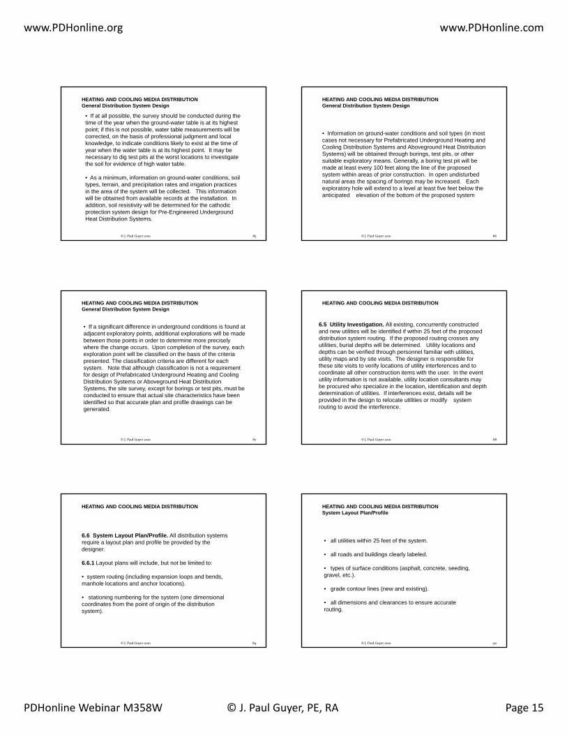
• If at all possible, the survey should be conducted during the time of the year when the ground-water table is at its highest point; if this is not possible, water table measurements will be corrected, on the basis of professional judgment and local knowledge, to indicate conditions likely to exist at the time of year when the water table is at its highest point. It may be necessary to dig test pits at the worst locations to investigate the soil for evidence of high water table
HEATING AND COOLING MEDIA DISTRIBUTIONGeneral Distribution System Design
the soil for evidence of high water table.
• As a minimum, information on ground-water conditions, soil types, terrain, and precipitation rates and irrigation practices in the area of the system will be collected. This information will be obtained from available records at the installation. In addition, soil resistivity will be determined for the cathodic protection system design for Pre-Engineered Underground Heat Distribution Systems.
85© J. Paul Guyer 2010
• Information on ground-water conditions and soil types (in most cases not necessary for Prefabricated Underground Heating and Cooling Distribution Systems and Aboveground Heat Distribution Systems) will be obtained through borings, test pits, or other suitable exploratory means. Generally, a boring test pit will be
HEATING AND COOLING MEDIA DISTRIBUTIONGeneral Distribution System Design
p y y g pmade at least every 100 feet along the line of the proposed system within areas of prior construction. In open undisturbed natural areas the spacing of borings may be increased. Each exploratory hole will extend to a level at least five feet below the anticipated elevation of the bottom of the proposed system
86© J. Paul Guyer 2010
• If a significant difference in underground conditions is found at adjacent exploratory points, additional explorations will be made between those points in order to determine more precisely where the change occurs. Upon completion of the survey, each exploration point will be classified on the basis of the criteria presented. The classification criteria are different for each system Note that although classification is not a requirement
HEATING AND COOLING MEDIA DISTRIBUTIONGeneral Distribution System Design
system. Note that although classification is not a requirement for design of Prefabricated Underground Heating and Cooling Distribution Systems or Aboveground Heat Distribution Systems, the site survey, except for borings or test pits, must be conducted to ensure that actual site characteristics have been identified so that accurate plan and profile drawings can be generated.
87© J. Paul Guyer 2010
6.5 Utility Investigation. All existing, concurrently constructed and new utilities will be identified if within 25 feet of the proposed distribution system routing. If the proposed routing crosses any utilities, burial depths will be determined. Utility locations and depths can be verified through personnel familiar with utilities, utility maps and by site visits. The designer is responsible for these site visits to verify locations of utility interferences and to
HEATING AND COOLING MEDIA DISTRIBUTION
these site visits to verify locations of utility interferences and to coordinate all other construction items with the user. In the event utility information is not available, utility location consultants may be procured who specialize in the location, identification and depth determination of utilities. If interferences exist, details will be provided in the design to relocate utilities or modify system routing to avoid the interference.
88© J. Paul Guyer 2010
6.6 System Layout Plan/Profile. All distribution systems require a layout plan and profile be provided by the designer.
6.6.1 Layout plans will include, but not be limited to:
HEATING AND COOLING MEDIA DISTRIBUTION
• system routing (including expansion loops and bends, manhole locations and anchor locations).
• stationing numbering for the system (one dimensional coordinates from the point of origin of the distribution system).
89© J. Paul Guyer 2010
• all utilities within 25 feet of the system.
• all roads and buildings clearly labeled.
• types of surface conditions (asphalt, concrete, seeding,
HEATING AND COOLING MEDIA DISTRIBUTIONSystem Layout Plan/Profile
yp ( p , , g,gravel, etc.).
• grade contour lines (new and existing).
• all dimensions and clearances to ensure accurate routing.
90© J. Paul Guyer 2010

www.PDHonline.org www.PDHonline.com
PDHonline Webinar M358W © J. Paul Guyer, PE, RA Page 16
6.6.2 A profile of the system will also be drawn and, as a minimum, show:
• all system stationing numbering.
• system slope drawn to scale (1-inch to 20 feet minimum for
HEATING AND COOLING MEDIA DISTRIBUTIONSystem Layout Plan/Profile
y p (all systems) to all low points.
• new and existing grade.
• all existing or new utilities shown at their actual burial depths.
91© J. Paul Guyer 2010
6.7 Expansion Compensation. All expansion systems, loops, and bends, will be sized in order to prevent excessive pipe stresses (due mainly from thermal expansion) from exceeding those allowed by the Power Piping Code, ASME B31.1. Mechanical expansion joints are not recommended for absorbing system expansion. Mechanical expansion joints greatly increase the maintenance requirements of the distribution systems. In the
lik l t th t i j i t t b d th t b
HEATING AND COOLING MEDIA DISTRIBUTION
unlikely event that expansion joints must be used, they must be placed in an adequately sized valve manhole. The designer is responsible for expansion calculations for Heat Distribution Systems in Concrete Trenches, Prefabricated Underground Heating/Cooling Distribution Systems, and Aboveground Heat Distribution Systems. The designer is also responsible for the expansion and stress determinations in all the valve manholes, including the location of the equipment/pipe support locations.
92© J. Paul Guyer 2010
Even though the manufacturer is responsible for the expansion calculations for Pre-Engineered Underground Heat Distribution Systems, the calculations will be thoroughly reviewed by the designer at the shop drawing review. It is recommended that a three dimensional finite element computer program be used for determining system stresses. Many finite element software packages are available which operate on desktop computers.
HEATING AND COOLING MEDIA DISTRIBUTIONExpansion Compensation
The temperature differential used in the stress analysis will be the maximum temperature of the media less the minimum temperature the system will encounter during a shutdown. All loops and bends will be sized based on zero percent cold springing. Cold springing effects lessen over time and are difficult to maintain in the event the system is ever cut, and shall therefore not be included in the analysis. However, loops may be installed with cold springing as an added conservative measure.
93© J. Paul Guyer 2010
6.8 Valve Manholes. For all distribution systems, valve manholes will be designed by the project designer. A valve manhole is required for all buried system lateral connections, all below to above ground system transitions, all drain points (low points), all below ground valving, all trap stations, high points for vents of buried systems, and to minimize depth of buried systems. Distance between valve manholes varies with
HEATING AND COOLING MEDIA DISTRIBUTION
systems. Distance between valve manholes varies with different applications. However, spacing shall never exceed 500 feet with Pre-Engineered Underground Heat Distribution Systems or Prefabricated Underground Heating/Cooling Distribution Systems to minimize excavation when searching for failures and to minimize effects of a failure. To enhance maintainability, avoid valve manholes deeper than 6 feet.
94© J. Paul Guyer 2010
6.8.1 Manhole internals. Layout of each manhole will be designed on a case by case basis.
6.8.1.1 Equipment/valve locations. It is important to first layout, to scale, all manhole piping, insulation, valving (with stems upright 90 degrees or less from vertical), and equipment and then locate the manhole walls around these
HEATING AND COOLING MEDIA DISTRIBUTIONValve Manholes
equipment and then locate the manhole walls around these appurtenances to ensure adequate manhole size and room for maintenance personnel. One line diagrams of piping and equipment are unacceptable. See Figure 6-1 for a typical manhole plan. Note that all valve manhole layouts have certain designer requirements in common. The designer will:
95© J. Paul Guyer 2010
HEATING AND COOLING MEDIA DISTRIBUTIONValve Manholes
Figure 6-1Typical Manhole
96© J. Paul Guyer 2010

www.PDHonline.org www.PDHonline.com
PDHonline Webinar M358W © J. Paul Guyer, PE, RA Page 17
• Provide main line isolation valves in valve manholes to most efficiently minimize outages to buildings served by the distribution system. When installed, main line isolation valves will be located downstream of the building's service laterals.
• Provide lateral isolation valves within the valve manholes for ll l t l
HEATING AND COOLING MEDIA DISTRIBUTIONValve Manholes
all laterals runs.
• Locate all carrier pipe vents and drains needed within the manhole for proper system drainage of the main and lateral lines.
• Layout all valve manhole internals (valves and valve stems, pipe w/insulation,
97© J. Paul Guyer 2010
• Layout all valve manhole internals (valves and valve stems, pipe w/insulation, access ladders, isolation flanges, and equipment) to scale to ensure adequate clearance has been provided for operation and maintenance within the manhole.
• Ensure no non-metallic piping is routed in the manholes (i.e.,
HEATING AND COOLING MEDIA DISTRIBUTIONValve Manholes
p p g ( ,as allowed with chilled water or condensate return systems) which also serves high temperature mediums that could damage the non-metallic piping. Damage to non-metallic piping is caused when manholes flood and the hot piping boils the flood water. Boiling water can exceed the temperature allowables of many nonmetallic piping materials. Because of this, the designer must transition to steel piping at the manholes.
98© J. Paul Guyer 2010
6.8.1.2 Clearances.Design will provide for clearance around piping
HEATING AND COOLING MEDIA DISTRIBUTIONValve Manholes
and equipment in the manhole in accordance with Table 6-1.
Table 6-1Manhole Clearances
99© J. Paul Guyer 2010
6.8.1.3 Access Ladders. Access ladders will be required on all valve manholes greater than 3 feet in depth. Ladders will be welded steel and will consist of uprights and nonslip steps or rungs. Uprights will be not less than 16 inches apart and steps or rungs will be spaced no greater than 12 inches apart. Ladders will extend not less than 6 inches from the manhole wall and will be firmly anchored to the wall by steel
HEATING AND COOLING MEDIA DISTRIBUTIONValve Manholes
inserts spaced not more than three 3 feet apart vertically. All parts of the ladders will be hot-dipped galvanized after fabrication in conformance with ASTM A 123. The top rung of the ladders shall be not more than 6 inches from the top of the manhole. A typical valve manhole access ladder detail is shown in Figure 6-2.
100© J. Paul Guyer 2010
HEATING AND COOLING MEDIA DISTRIBUTIONValve Manholes
101© J. Paul Guyer 2010
Figure 6-2
6.8.1.4 Insulation. Insulation for valves, fittings, field casing closures, and other piping system accessories in valve manholes will be of the same types and thicknesses as those provided in the distribution systems' guide specification. All insulation will be premolded, precut, or job fabricated to fit and will be removable and reusable. Insulation jackets will be
id d f ll i i l ti i h l d ill l
HEATING AND COOLING MEDIA DISTRIBUTIONValve Manholes
provided for all pipe insulation in manholes and will comply with the requirements of the particular distribution system guide specification.
.
102© J. Paul Guyer 2010

www.PDHonline.org www.PDHonline.com
PDHonline Webinar M358W © J. Paul Guyer, PE, RA Page 18
6.8.1.5 Isolation flanges. Isolation flanges will be provided when connecting to an existing cathodically protected heating or cooling distribution system or to prevent a new system's cathodic protection system from contacting an existing system. The isolation flanges will be installed in the valve manhole and a typical flange detail is shown in Figure 6-3
HEATING AND COOLING MEDIA DISTRIBUTIONValve Manholes
manhole and a typical flange detail is shown in Figure 6-3.
103© J. Paul Guyer 2010
HEATING AND COOLING MEDIA DISTRIBUTIONValve Manholes
Figure 6-3
104© J. Paul Guyer 2010
6.8.1.6 Valve/piping supports. Piping in valve manholes often will need supports within the manhole especially when larger valves or equipment are attached to the piping. These supports will be located on the manhole plans as determined by the designer's expansion compensation calculations for each
HEATING AND COOLING MEDIA DISTRIBUTIONValve Manholes
designer s expansion compensation calculations for each manhole valving and equipment layout. Typical valve/piping support details are shown in Figure 6-4.
105© J. Paul Guyer 2010
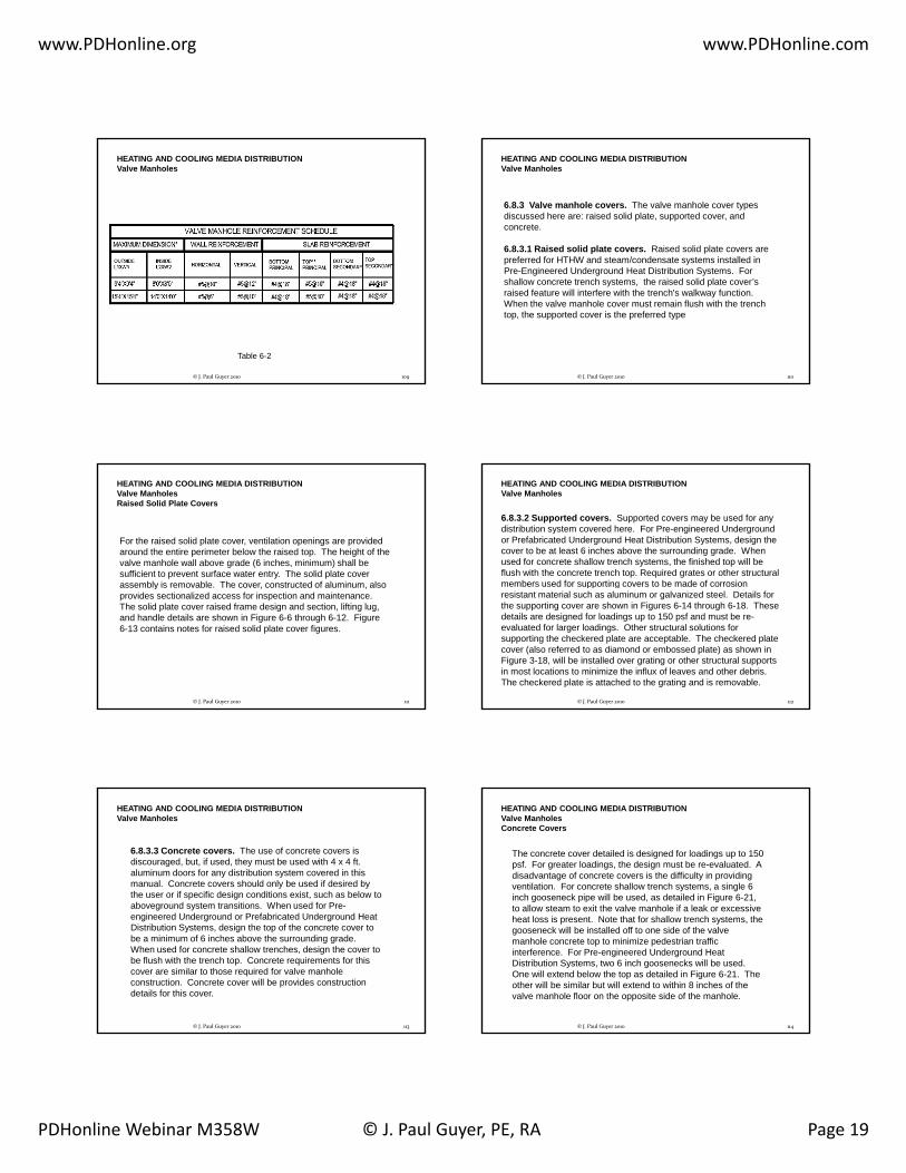
6.8.2 Valve manhole construction. Valve manholes will be field constructed of reinforced concrete conforming to the current criteria. Valve manholes will be constructed of 4,000 psi minimum compressive strength concrete. Reinforcing bars will conform to ASTM A 615, grade 60. Typical reinforcing steel details and sizing are shown in Figure 6-5 and Table 6-2 respectively. Concrete floor slabs and walls will be of sufficient weight to prevent flotation in high water table areas. Floor slabs
HEATING AND COOLING MEDIA DISTRIBUTIONValve Manholes
weight to prevent flotation in high water table areas. Floor slabs will be sloped to the drain which will be installed in the floor slab. Concrete wall sections will be not less than 8 inches thick and must meet anticipated load and soil conditions. Side walls will be constructed in a monolithic pour. Water stops will be provided at all construction joints. Do not locate valve manholes in roads or parking areas which create an inadequate amount of manhole ventilation and poor access.
106© J. Paul Guyer 2010
HEATING AND COOLING MEDIA DISTRIBUTIONValve Manholes
Figure 6-4
107© J. Paul Guyer 2010
HEATING AND COOLING MEDIA DISTRIBUTIONValve Manholes
Figure 6-5
108© J. Paul Guyer 2010
www.PDHonline.org www.PDHonline.com
PDHonline Webinar M358W © J. Paul Guyer, PE, RA Page 19
HEATING AND COOLING MEDIA DISTRIBUTIONValve Manholes
Table 6-2
109© J. Paul Guyer 2010
6.8.3 Valve manhole covers. The valve manhole cover types discussed here are: raised solid plate, supported cover, and concrete.
6.8.3.1 Raised solid plate covers. Raised solid plate covers are preferred for HTHW and steam/condensate systems installed in
HEATING AND COOLING MEDIA DISTRIBUTIONValve Manholes
preferred for HTHW and steam/condensate systems installed in Pre-Engineered Underground Heat Distribution Systems. For shallow concrete trench systems, the raised solid plate cover’s raised feature will interfere with the trench's walkway function. When the valve manhole cover must remain flush with the trench top, the supported cover is the preferred type
110© J. Paul Guyer 2010
For the raised solid plate cover, ventilation openings are provided around the entire perimeter below the raised top. The height of the valve manhole wall above grade (6 inches, minimum) shall be sufficient to prevent surface water entry. The solid plate cover assembly is removable The cover constructed of aluminum also
HEATING AND COOLING MEDIA DISTRIBUTIONValve ManholesRaised Solid Plate Covers
assembly is removable. The cover, constructed of aluminum, also provides sectionalized access for inspection and maintenance. The solid plate cover raised frame design and section, lifting lug, and handle details are shown in Figure 6-6 through 6-12. Figure 6-13 contains notes for raised solid plate cover figures.
111© J. Paul Guyer 2010
6.8.3.2 Supported covers. Supported covers may be used for any distribution system covered here. For Pre-engineered Underground or Prefabricated Underground Heat Distribution Systems, design the cover to be at least 6 inches above the surrounding grade. When used for concrete shallow trench systems, the finished top will be flush with the concrete trench top. Required grates or other structural members used for supporting covers to be made of corrosion
HEATING AND COOLING MEDIA DISTRIBUTIONValve Manholes
members used for supporting covers to be made of corrosion resistant material such as aluminum or galvanized steel. Details for the supporting cover are shown in Figures 6-14 through 6-18. These details are designed for loadings up to 150 psf and must be re-evaluated for larger loadings. Other structural solutions for supporting the checkered plate are acceptable. The checkered plate cover (also referred to as diamond or embossed plate) as shown in Figure 3-18, will be installed over grating or other structural supports in most locations to minimize the influx of leaves and other debris. The checkered plate is attached to the grating and is removable.
112© J. Paul Guyer 2010
6.8.3.3 Concrete covers. The use of concrete covers is discouraged, but, if used, they must be used with 4 x 4 ft. aluminum doors for any distribution system covered in this manual. Concrete covers should only be used if desired by the user or if specific design conditions exist, such as below to aboveground system transitions. When used for Pre-
HEATING AND COOLING MEDIA DISTRIBUTIONValve Manholes
engineered Underground or Prefabricated Underground Heat Distribution Systems, design the top of the concrete cover to be a minimum of 6 inches above the surrounding grade. When used for concrete shallow trenches, design the cover to be flush with the trench top. Concrete requirements for this cover are similar to those required for valve manhole construction. Concrete cover will be provides construction details for this cover.
113© J. Paul Guyer 2010
The concrete cover detailed is designed for loadings up to 150 psf. For greater loadings, the design must be re-evaluated. A disadvantage of concrete covers is the difficulty in providing ventilation. For concrete shallow trench systems, a single 6 inch gooseneck pipe will be used, as detailed in Figure 6-21, to allow steam to exit the valve manhole if a leak or excessive
HEATING AND COOLING MEDIA DISTRIBUTIONValve ManholesConcrete Covers
to allow steam to exit the valve manhole if a leak or excessive heat loss is present. Note that for shallow trench systems, the gooseneck will be installed off to one side of the valve manhole concrete top to minimize pedestrian traffic interference. For Pre-engineered Underground Heat Distribution Systems, two 6 inch goosenecks will be used. One will extend below the top as detailed in Figure 6-21. The other will be similar but will extend to within 8 inches of the valve manhole floor on the opposite side of the manhole.
114© J. Paul Guyer 2010

www.PDHonline.org www.PDHonline.com
PDHonline Webinar M358W © J. Paul Guyer, PE, RA Page 20
6.8.4 Valve manhole drainage. Drainage of water from the valve manhole is mandatory for the successful operation and longevity of buried heating or cooling distribution systems. There are three types of valve manhole drainage systems described in this manual:
HEATING AND COOLING MEDIA DISTRIBUTIONValve Manholes
types of valve manhole drainage systems described in this manual: gravity drainage, pumped drainage from a sump basin, and pumped drainage from the valve manhole.
115© J. Paul Guyer 2010
6.8.4.1 Gravity drainage. The most cost effective and lowest maintenance system is gravity drainage to a storm drain when location, depth of existing storm drains, and local regulatory requirements allow this possibility. Drainage lines will be 6 inches in diameter minimum and will conform to the latest storm drain criteria and will be sloped at one percent, minimum. Valve manhole
HEATING AND COOLING MEDIA DISTRIBUTIONValve ManholesValve Manhole Drainage
criteria and will be sloped at one percent, minimum. Valve manhole outlet will be a floor drain with backflow preventer to prevent storm water inflow from the storm drain (see Figure 6-22). Note that valve manhole drain outlets shall be covered with a "hat type" cast iron pipe screen to minimize the accumulation of trash over the drain inlet. Also, the manhole floor will be sloped toward the drain.
116© J. Paul Guyer 2010
6.8.4.2 Pumped drainage from sump basin. For pumped drainage, a duplex submersible pump system installed in a remote sump basin may be provided as indicated in Figures 6-23 and 6-24. The sump basin will be located no more than 10 feet from the valve manhole. Drainage from the valve manhole to the sump basin will be similar to
HEATING AND COOLING MEDIA DISTRIBUTIONValve ManholesValve Manhole Drainage
drainage to a storm drain including the valve manhole floor drain (Figure 6-22). Discharge from the pumps can be routed to a splashblock at grade or to an adjacent storm sewer. Design of the surrounding grade must ensure drainage away from the sump basin, valve manhole and concrete shallow trench (if used) when discharging to grade. A power pedestal complete with failure warning light will be provided with each basin as shown in Figure 6-25
117© J. Paul Guyer 2010
A typical wiring diagram and sequence of operation are shown in Figure 6-26. A specification for the sump basin system can be included in the applicable manhole or heat distribution section of the contract specification. The sump basin design has proven to operate well even in the colder climates of the upper tier states in
HEATING AND COOLING MEDIA DISTRIBUTIONValve ManholesValve Manhole DrainagePumped Drainage from Sump Basin
the continental United States. It is also an excellent method to retrofit existing manholes that currently do not drain properly. The remote sump basin increases the life of the systems by removing the sump pump and pump controls from the hot, humid environment of the manhole. Also, pump maintenance will be done outside of the manhole. The pumps are easily disconnected and lifted to grade. The sump pumps used in the sump basin must incorporate the design characteristics listed in Table 6-3.
118© J. Paul Guyer 2010
6.8.4.3 Pumped drainage from valve manhole. Another means to pump water from the manhole is to locate the duplex sump pumps in the valve manhole. Typically, a 2'0" by 2'0" by 1'0" (deep) sump will be provided in a corner of the
l h l Th d l ill b i t ll d t
HEATING AND COOLING MEDIA DISTRIBUTIONValve ManholesValve Manhole Drainage
valve manhole. The duplex sump pumps will be installed to pump out of this sump. Valve manhole sump pump electrical arrangement should be installed as shown in Figure 6-27. The control panel with high level warning light will be mounted adjacent to the valve manhole at grade.
119© J. Paul Guyer 2010
This keeps the electrical panel out of the hot, humid environment of the manhole. The sequence of operation and wiring diagrams will meet the requirements of Figure 6-26. Pump discharge can be routed to a splashblock at grade ( i il t th b i di h i i t
HEATING AND COOLING MEDIA DISTRIBUTIONValve ManholesValve Manhole DrainagePumped drainage from valve manhole
(similar to the sump basin discharge piping arrangement on Figure 6-23) or to an adjacent storm drain. Electric sump pumps used in the valve manholes must incorporate the design characteristics listed in Table 6-3. Note that life of the pumps are typically shortened when installed in the hot and humid valve manhole environment.
120© J. Paul Guyer 2010

www.PDHonline.org www.PDHonline.com
PDHonline Webinar M358W © J. Paul Guyer, PE, RA Page 21
HEATING AND COOLING MEDIA DISTRIBUTIONValve ManholesValve Manhole Drainage
Table 6-3
121© J. Paul Guyer 2010
6.8.5 General.
6.8.5.1 Valve manhole wall penetrations. A design must be provided for the distribution system wall penetrations. For a shallow trench system, the wall penetrations will typically be the same size as the inside dimension of the shallow trench connecting to the valve manhole Structural reinforcement must
HEATING AND COOLING MEDIA DISTRIBUTIONValve Manholes
connecting to the valve manhole. Structural reinforcement must be designed around this opening. Drainage from the trench will then flow into the manhole. For Pre-engineered or Prefabricated Underground Heat Distribution Systems, sleeved openings will typically be provided with an expandable seal between the casing and the pipe sleeve as indicated on Figure 6-28. Structural reinforcement must be designed to avoid contact with the pipe sleeve and water stop to prevent grounding of the system's cathodic protection.
122© J. Paul Guyer 2010
6.8.5.2 Waterproofing. Waterproof membranes will be placed in or below the concrete bottom slab and continued up the outer sides to the top of the sidewalls in accordance with the valve manhole guide specification.
6.8.5.3 Pipe anchoring adjacent to valve manholes.R dl f th b i d di t ib ti t i h
HEATING AND COOLING MEDIA DISTRIBUTIONValve Manholes
Regardless of the buried distribution system, pipe anchors should be provided between 2 to 5 feet of a manhole wall to minimize movement through the manhole. For piping which passes through valve manholes, anchoring on one side only is typically adequate. Anchoring piping on more than one side may restrict piping movement and overstress the piping in the valve manhole.
123© J. Paul Guyer 2010
Anchors will typically be provided as part of the distribution system and will not be embedded in the manhole wall. However, if the manhole is used to support an anchor, the manhole must be designed to withstand the forces exerted by the system. Expansion
HEATING AND COOLING MEDIA DISTRIBUTIONValve ManholesPipe anchoring adjacent to valve manholes
compensation stress calculation will always be conducted to ensure proper anchor locations throughout the distribution system. These calculations must also account for the expansion in the valve manholes.
124© J. Paul Guyer 2010
6.8.5.4 Piping materials in valve manholes. Nonmetallic piping must not be used in the same valve manholes as piping carrying higher temperature media that could cause the temperature around the non-metallic piping to exceed the allowables and potentially cause permanent damage to the non-metallic piping. In addition chilled water systems with PVC carrier piping must
HEATING AND COOLING MEDIA DISTRIBUTIONValve Manholes
In addition, chilled water systems with PVC carrier piping must never be installed in the same valve manhole with any heating system.
125© J. Paul Guyer 2010
HEATING AND COOLING MEDIA DISTRIBUTIONValve Manholes
126© J. Paul Guyer 2010
Figure 6-6

www.PDHonline.org www.PDHonline.com
PDHonline Webinar M358W © J. Paul Guyer, PE, RA Page 22
HEATING AND COOLING MEDIA DISTRIBUTIONValve Manholes
SECTION A-A OF RAISED COVER PLATEFigure 6-7
127© J. Paul Guyer 2010
HEATING AND COOLING MEDIA DISTRIBUTIONValve Manholes
SECTION B-B OF RAISED COVER PLATEFigure 6-8
128© J. Paul Guyer 2010
HEATING AND COOLING MEDIA DISTRIBUTIONValve Manholes
129© J. Paul Guyer 2010
SECTION C-C OF RAISED COVER PLATEFigure 6-9
HEATING AND COOLING MEDIA DISTRIBUTIONValve Manholes
Figure 6-10
130© J. Paul Guyer 2010
HEATING AND COOLING MEDIA DISTRIBUTIONValve Manholes
Figure 6-11
131© J. Paul Guyer 2010
HEATING AND COOLING MEDIA DISTRIBUTIONValve Manholes
Figure 6-12
132© J. Paul Guyer 2010

www.PDHonline.org www.PDHonline.com
PDHonline Webinar M358W © J. Paul Guyer, PE, RA Page 23
HEATING AND COOLING MEDIA DISTRIBUTIONValve Manholes
Figure 6-13
133© J. Paul Guyer 2010
HEATING AND COOLING MEDIA DISTRIBUTIONValve Manholes
Figure 6-14
134© J. Paul Guyer 2010
HEATING AND COOLING MEDIA DISTRIBUTIONValve Manholes
Angle Support for Grating
Figure 6-15
135© J. Paul Guyer 2010
HEATING AND COOLING MEDIA DISTRIBUTIONValve Manholes
Structural Support for GratingFigure 6-16
136© J. Paul Guyer 2010
HEATING AND COOLING MEDIA DISTRIBUTIONValve Manholes
Figure 6-17
137© J. Paul Guyer 2010
HEATING AND COOLING MEDIA DISTRIBUTIONValve Manholes
Figure 6-18
138© J. Paul Guyer 2010

www.PDHonline.org www.PDHonline.com
PDHonline Webinar M358W © J. Paul Guyer, PE, RA Page 24
HEATING AND COOLING MEDIA DISTRIBUTIONValve Manholes
Figure 6-19
139© J. Paul Guyer 2010
HEATING AND COOLING MEDIA DISTRIBUTIONValve Manholes
Figure 6-20
140© J. Paul Guyer 2010
HEATING AND COOLING MEDIA DISTRIBUTIONValve Manholes
Typical Gooseneck
Figure 6-21
141© J. Paul Guyer 2010
HEATING AND COOLING MEDIA DISTRIBUTIONValve Manholes
Valve Manhole Floor DrainFigure 6-22
142© J. Paul Guyer 2010
HEATING AND COOLING MEDIA DISTRIBUTIONValve Manholes
Figure 6-23143
© J. Paul Guyer 2010
HEATING AND COOLING MEDIA DISTRIBUTIONValve Manholes
Figure 6-24
144© J. Paul Guyer 2010

www.PDHonline.org www.PDHonline.com
PDHonline Webinar M358W © J. Paul Guyer, PE, RA Page 25
HEATING AND COOLING MEDIA DISTRIBUTIONValve Manholes
Sump Basin Electrical DetailsFigure 3-25
145© J. Paul Guyer 2010
HEATING AND COOLING MEDIA DISTRIBUTIONValve Manholes
Figure 6-26
146© J. Paul Guyer 2010
HEATING AND COOLING MEDIA DISTRIBUTIONValve Manholes
Valve Manhole Sump Electrical Details
Figure 6-27
147© J. Paul Guyer 2010
HEATING AND COOLING MEDIA DISTRIBUTIONValve Manholes
Figure 6-28
148© J. Paul Guyer 2010
6.9 Special Considerations
Although it is impractical to cover all special considerations, which arise in heating and cooling distribution designs, this discussion presents typical design problems and solutions associated withsteam, high temperature hot water, low temperature hot water and chilled water systems.
6.9.1 Steam Systems
HEATING AND COOLING MEDIA DISTRIBUTION
6.9.1.1 Trap Selection. Steam traps are used to separate the condensate and non-condensable gases from the steam. Many types of traps are used on drip legs for steam distribution systems. Those trap types include float and thermostatic (F&T), inverted bucket, thermostatic and thermodynamic (disc). However, for buried heat distribution drip leg applications, inverted bucket or thermostatic (bimetallic type) should be the trap types selected. For drip leg applications where freezing is a consideration, thermodynamic type (installed vertically) or bimetallic thermostatic type should be selected.
149© J. Paul Guyer 2010
6.9.1.2 Trap Sizing and Location. Trap sizing is important for obtaining an efficient steam distribution system. Condensation in the steam line is caused by heat loss from the steam line. Trap life will be shortened, function affected and excessive energy will be wasted if traps are oversized to handle the higher initial startup condensate flows. Therefore, the traps should be sized for the condensate load seen during the distribution system normal operation. Because the traps are not sized for startup loadings the bypass must be opened at startup to allow
HEATING AND COOLING MEDIA DISTRIBUTIONSpecial ConsiderationsSteam Systems
startup loadings, the bypass must be opened at startup to allow condensate to pass until the steam line has reached normal operatingtemperatures. The designer will calculate heat loss and condensate flow for that particular design using a recommended method for determining condensate loads during normal operation. It is critical that the designer calculate trap capacity using the method for each trap station in the design to ensure proper steam system operation. In addition to trap capacity, steam trap type, differential pressures, and inlet pressure must always be provided on the contract documents. Do not locate steam drip legs, with associated traps, more than 500 feet apart.
150© J. Paul Guyer 2010

www.PDHonline.org www.PDHonline.com
PDHonline Webinar M358W © J. Paul Guyer, PE, RA Page 26
6.9.1.3 Drip Leg Sizing. Drip legs, installed vertically down from the steam pipe, are used to collect condensate. Design all steam lines to slope at 1 inch in 20 feet minimum toward these drip legs. It is preferable to slope the steam lines in the direction of steam flow whenever possible. The steam trap line and bypass line are connected to the drip leg in an approved manner. The drip leg will be the same nominal pipe size as the main line (up to a 12-inch
HEATING AND COOLING MEDIA DISTRIBUTIONSpecial ConsiderationsSteam Systems
be the same nominal pipe size as the main line (up to a 12 inch line) and will provide a storage capacity equal to 50% of the startup condensate load (no safety factor, one-half of an hour duration) for line sizes 4 inches in diameter and larger and 25% of the startup condensate load (no safety factor, one-half of an hour duration) for line sizes less than 4 inches. In no case will the drip leg be less than 18 inches in length or larger than 12 inches in diameter for all steam line sizes. The designer will calculate startup loads for drip leg sizing using approved methods.
151© J. Paul Guyer 2010
6.9.1.4 Trap Station Layout. Valve and strainer sizes will match the line sizes on which they are installed. Pipe lines to and from the steam trap will be sized based on calculated trap capacity but will be no less than 3/4-inch nominal size. If reducing fittings are needed at the trap inlet and outlet, eccentric reducers must be used. The bypass line will be sized to accommodate warm-up
HEATING AND COOLING MEDIA DISTRIBUTIONSpecial ConsiderationsSteam Systems
yp pcondensate loads. For steam systems with an operating pressure of 150 psig or less and pipe sizes 12 inches or less, provide a ¾-inch bypass line. If the condensate return main is a low pressure or gravity flow type, the trap discharge line will be routed through an accumulator,. The accumulator will lower the trap discharge
152© J. Paul Guyer 2010
temperature and minimize flashing when the condensate is introduced into sloped condensate lines which are routed to receiver/pump sets located in valve manholes. The pumps push the condensate back to the central plant in a separate pressurized condensate line. This type of condensate return system is referred
HEATING AND COOLING MEDIA DISTRIBUTIONSpecial ConsiderationsSteam SystemsTrap Station Layout
yp yto as a "three pipe" or a "pumped return" system. If the steam pressure is sufficiently high, it may be used to force the condensate through the condensate return system to the central plant. No accumulator is required for this type system, which is referred to as a "two pipe" system. Sizing of the lines for both of these systems is presented later in thischapter.
153© J. Paul Guyer 2010
6.9.1.5 Condensate Cooling System. Fiberglass reinforced plastic (FRP) piping is usually allowed for most condensate return systems. Since internal corrosion is a frequent problem in steel condensate lines, FRP eliminates this problem. However, the FRP materials
HEATING AND COOLING MEDIA DISTRIBUTIONSpecial ConsiderationsSteam Systems
cannot withstand as high of pressures or temperatures as steel and often fail when exposed to these conditions. A common temperature in an FRP distribution piping system where damage will occur is 250 deg. F. Condensate temperatures may exceed 250 deg. F. at the outlet of steam drip leg traps on steam systems that have pressures greater than 15 psig
154© J. Paul Guyer 2010
In order to use FRP condensate lines in this case, a condensate cooling system must be employed. In this system, the high temperature condensate is discharged into a cooling tank where it blends with the system condensate. The blended condensate is then routed to the condensate main. The FRP (or non-metallic) pipe
HEATING AND COOLING MEDIA DISTRIBUTIONSpecial ConsiderationsSteam SystemsCondensate Cooling System
( ) p ptransitions to steel inside the valve manhole to avoid burying the transition point. Also, nonmetallic piping will not be allowed in a manhole with high temperature hot water or high pressure steam systems due to the potential for this pipe being exposed to damaging temperatures within the manhole if the manhole floods or the carrier pipe on the heating system leaks.
155© J. Paul Guyer 2010
6.9.1.6 Non-metallic Pipe Anchors in Valve Manholes. If anchoring of a non-metallic piping system is required at the valve manhole wall to comply with the distribution system stress analysis. If the system is to be anchored at both of the valve manhole wall penetrations, provide adequate piping b d i th h l t d t th i
HEATING AND COOLING MEDIA DISTRIBUTIONSpecial ConsiderationsSteam Systems
bends in the manhole to accommodate the expansion between the two anchors. Steel straps and bolts will be sized to accommodate the axial force of that particular piping layout. These sizes will be entered on the detail. Also, valve manhole sizes must be large enough to accommodate the anchors and still allow for maintenance access.
156© J. Paul Guyer 2010

www.PDHonline.org www.PDHonline.com
PDHonline Webinar M358W © J. Paul Guyer, PE, RA Page 27
6.8.1.7 Pipe Sizing. Pipe sizing is critical to proper operation of both the steam and the condensate return systems.
6.8.1.7.1 Steam. There are several methods to size steam lines. One of the quickest and most popular methods is using pressure drop ers s flo rate charts hich pro ide steam elocities based on the
HEATING AND COOLING MEDIA DISTRIBUTIONSpecial Considerations
versus flow rate charts, which provide steam velocities based on the requiredflow and pressure drops. The American Society of Heating, Refrigeration, and Air Conditioning Engineers (ASHRAE) Fundamentals Handbook, Chapter "Pipe Sizing", is a good source for these steam sizing tables. Recommended velocities for various system pressure ranges are:
157© J. Paul Guyer 2010
0 - 10 psig, saturated - 1,000 to 4,000 fpm10 - 50 psig, saturated - 4,000 to 8,000 fpm50 - 150 psig, saturated - 8,000 to 12,000 fpm
In addition, ensure the total pressure drop in the system will not be excessive. Steam pressure must be high enough at the end users to
HEATING AND COOLING MEDIA DISTRIBUTIONSpecial Considerations
excessive. Steam pressure must be high enough at the end users to meet all special process requirements
158© J. Paul Guyer 2010
6.8.1.7.2 Condensate. As described previously, there are basically two types of condensate return systems used on central heating systems: the two pipe system (which uses steam pressure to force condensate back to the plant) and the three pipe, or pumped return, system.
HEATING AND COOLING MEDIA DISTRIBUTIONSpecial Considerations
159© J. Paul Guyer 2010
6.8.1.8 Steam System Material Selection
6.8.1.8.1 Valves. For high-pressure steam systems (125 psig or greater), valves will be 300-pound class and will have welded ends. Steam and condensate valves at lower pressures will be 150-pound class with weldedends. Valves on trap stations, including the bypass valve, will be 150-pound class with threaded ends
HEATING AND COOLING MEDIA DISTRIBUTIONSpecial Considerations
150-pound class with threaded ends.
6.8.1.8.2 Fittings. All fittings in the steam distribution system, except as discussed for valves, will be welded except at equipment, traps, strainers, and items which require frequent removal. These items will be threaded or flanged.
6.8.1.8.3 Piping. Steam and condensate piping will usually be carbon steel conforming to ASTM A 53, Grade B, Type E or S. Steam piping will be schedule 40. Condensate lines will be schedule 80 as will all welded piping less than 1-1/2 inches.
160© J. Paul Guyer 2010
6.8.2 HTHW Systems
6.8.2.1 Pipe Sizing. Sizing lines for High Temperature Hot Water (HTHW) systems is similar to any water system, except at high temperatures water becomes less dense and less viscous, and, therefore, the mass flow rate of the system must be calculated considering the lower density (usually temperatures are around 400 deg. F for HTHW). Recommended velocities for various HTHW flows are as follows:
HEATING AND COOLING MEDIA DISTRIBUTIONSpecial Considerations
for various HTHW flows are as follows:
Up to 10,000 lbm/hr - 1 to 2 feet/sec10,000 to 30,000 lbm/hr - 2 to 3 feet/sec30,000 to 200,000 lbm/hr - 3 to 5 feet/sec200,000 lbm/hr on up - (use velocity to accommodate 0.50 psi/100 ft., maximum)
161© J. Paul Guyer 2010
6.8.2.2 HTHW System Material Selection
6.8.2.2.1 Valves. All valves on HTHW systems will be 300-pound class with welded ends. Shutoff (isolation) valves will be gate type. Valve packings must be capable of handling the pressures and temperatures associated with HTHW systems.
HEATING AND COOLING MEDIA DISTRIBUTIONSpecial Considerations
6.8.2.2.2 Fittings. All fittings on HTHW systems will be welded. The only exceptions will be specialty equipment such as dielectric flanges used to isolate the piping system from a cathodically protected system.
6.8.2.2.3 Piping. HTHW piping will be carbon steel conforming to ASTM A53, Grade B, Type E or S. All piping will be schedule 40 except for welded pipe less than 1-1/2 inches, which will be schedule 80.
162© J. Paul Guyer 2010

www.PDHonline.org www.PDHonline.com
PDHonline Webinar M358W © J. Paul Guyer, PE, RA Page 28
6.8.3 LTHW and CW Systems
6.8.3.1 Pipe Sizing. The most efficient method of determining pipe size for Low Temperature Hot Water (LTHW) and Chillled Water (CW) systems is to use head loss vs. flow rate charts such as those found in ASHRAE F ndamentals Chapter "Pipe Si ing" These tables are
HEATING AND COOLING MEDIA DISTRIBUTIONSpecial Considerations
ASHRAE Fundamentals, Chapter "Pipe Sizing". These tables are based on 60 deg. F water so for chilled water pipe sizing there is little error introduced using these charts. For LTHW systems, the use of the charts does introduce some error. However, the error is on the conservative side (the charts overstate the pressure drop of LTHW).
163© J. Paul Guyer 2010
6.8.3.2 LTHW and CW Material Selection.
6.8.3.2.1 Valves. Typically, valves on either LTHW or CW systems will be 150-pound class and will be located in the valve manholes. Ball valves provide a good means for line isolation. Although nonmetallic valves are sometimes allowed for these systems, metallic valves should be used for durability.
HEATING AND COOLING MEDIA DISTRIBUTIONSpecial Considerations
164© J. Paul Guyer 2010
6.8.3.2.2 Piping. The most common piping materials used for LTHW and CW systems are steel, copper tubing, reinforced thermosetting resin pipe (fiber- glass) and, for CW only, polyvinyl chloride and polyethylene. However, do not include nonmetallic piping in the same valve manholes with HTHW and steam systems. Chilled water lines using PVC piping must be installed i t l h l i PVC b th ll
HEATING AND COOLING MEDIA DISTRIBUTIONSpecial ConsiderationsLTHW and CW Material Selection
in separate valve manholes since PVC can be thermally damaged at relatively low temperatures. Outside the valve manholes, a separation of 15 feet (minimum) must be maintained between pre-engineered underground HTHW and steam systems and PVC encased, prefabricated underground heating/cooling distribution systems to avoid thermal degradation of the PVC.
165© J. Paul Guyer 2010
HEATING AND COOLING MEDIA DISTRIBUTIONSpecial Considerations
Figure 6-1166© J. Paul Guyer 2010
HEATING AND COOLING MEDIA DISTRIBUTIONSpecial Considerations
Duplex Condensate PumpFigure 6-2
167© J. Paul Guyer 2010
Table 6-1Pipe sizing guidelines for condensate return systems.
TWO-PIPE SYSTEM SIZING GUIDELINES
• DETERMINE CONDENSATE LINE PRESSURE (AS OBSERVED FROM ON-SITEPRESSURE GAGES).
• DETERMINE CONDENSATE LOAD (lbm/hr) FROM CENTRAL PLANT LOGS AND OTHERINPUT.
• ASSUME CONDENSATE AT TRAP DISCHARGE IS A COMBINATION OF CONDENSATE AND FLASH STEAM.
HEATING AND COOLING MEDIA DISTRIBUTIONSpecial Considerations
• SIZE LINE TO ACCOMMODATE 5,000 ft/min STEAM AND CONDENSATE MIXTUREVELOCITY AND TO ENSURE MIXTURE PRESSURE IS HIGH ENOUGH TO OVERCOME LINE LOSSES.
THREE-PIPE SYSTEM SIZING GUIDELINES•GRAVITY LINE: SLOPE AT 1 inch/20 feet (MINIMUM) TOWARD RECEIVER.•TOTAL PRESSURE DROP LESS THAN 0.25 psi.
•LINE SIZE WILL BE TWO (2) INCHES.
•PUMPED LINE: SIZE PUMPS TO MOVE CONDENSATE TO THE CENTRAL PLANT AT THE REQUIRED HEAD AT 200 deg. F.
168© J. Paul Guyer 2010

www.PDHonline.org www.PDHonline.com
PDHonline Webinar M358W © J. Paul Guyer, PE, RA Page 29
And now….
THE QUIZ
© J. Paul Guyer 2010 169
THE QUIZ
1. For the following conditions: U = 0.05 BTU/(Hr Ft2 F0), A = 500 Ft2, Ti = 68 F0, To = 30 F0, the heating load for the inside of a building due to transmission thru a wall of the given size and thermodynamic characteristics is ___________ BTU/Hr.
a. 650b. 750c. 850d. 950
© J. Paul Guyer 2010 170
2. 50 CFM of 40 F0 outside air is introduced into a room by infiltration and ventilation. The indoor design temperature for the room is Ti = 68 F0. The heating load imposed on the room by this infiltration and ventilation is about _______________ BTU/Hr.
a. 1540b. 1740c. 1940d. 2140
3. 500 CFM is exhausted from a room to the outside. The amount of outdoor air that should be introduced into the room to compensate for this exhaust air is about ___________ CFM.
a. 460b. 560c. 660d. 760
4 A b ildi i h t d i t itt tl (i h t d d i th d
© J. Paul Guyer 2010 171
4. A building is heated intermittently (i.e. heated during the day, but not at night) using a steam boiler. The boiler capacity should be oversized by about ____________ percent to allow for “pickup” in the morning after being turned off on cold nights.
a. 5b. 7c. 10d. 15
5. For the following conditions: U = 0.15 BTU/(Hr Ft2 F0), A = 5000 Ft2, Ti = 78 F0, To = 90 F0, the cooling load for the inside of a building due to transmission thru a roof of the given size and thermodynamic characteristics is ___________ BTU/Hr.
a. 8000b. 9000c. 10000d. 11000
© J. Paul Guyer 2010 172
6. A typical ventilation (i.e. introduction of outside air into the space) rate for offices is __________ CFM/person.
a. 5b. 10c. 15d. 20
7. The sensible heat load imposed on a gymnasium cooling system is about ________ Btu/Hr-person.
a. 635b. 735c. 835d. 935
8. A 1000 watt electric appliance in an air conditioned space has
© J. Paul Guyer 2010 173
8. A 1000 watt electric appliance in an air conditioned space has an equipment use factor of 50%. The sensible cooling load this appliance will impose on the air conditioning system is about ___________ Btu/Hr.
a. 1400b. 1500c. 1600d. 1700
9. A well designed and constructed air distribution duct system should not leak more than about _______________ percent supply air.
a. 0b. 3c. 5d. 10
© J. Paul Guyer 2010 174
10. Use of unitary air conditioning systems should be limited to loads less than about __________________ tons.
a. 50b. 100c. 150d. 200

www.PDHonline.org www.PDHonline.com
PDHonline Webinar M358W © J. Paul Guyer, PE, RA Page 30
11. A constant-volume, multi-zone cooling system should be used to provide individual temperature control to not more than __________ zones from a central air handler.
a. 3b. 5c. 7d. 10
© J. Paul Guyer 2010 175
12. A variable air volume (VAV) system may be a good choice for a building with more than ________ zones and load variation to permit reduction of fan capacity for significant periods of the day.
a. 5b. 10c. 15d. 20
13. Use ____________ air distribution ducts wherever possible.
a. rectangularb. roundc. squared. linear
14. A rule-of-thumb for the sizing of air conditioning cooling
© J. Paul Guyer 2010 176
14. A rule of thumb for the sizing of air conditioning cooling systems for administrative office buildings is ____________ SF/ton.
a. 450 to 600b. 600 to 750c. 750 to 900d. 900 to 1000
15. A rule-of-thumb for sizing a steam heating system is about _________ pound(s) of steam per 1000 Btu/Hr of heating load.
a. 0.5b. 1c. 1.5d. 2
© J. Paul Guyer 2010 177
16. High temperature hot water systems distribute heating water at temperatures above:
a. 150 deg Fb. 212 deg Fc. 250 deg Fd. 300 deg F
17. Condensate return systems are a feature of:
a. high temperature hot water systemsb. low temperature hot water systemsc. steam systemsd. chilled water systems
18. For high temperature water and steam/condensate systems
© J. Paul Guyer 2010 178
18. For high temperature water and steam/condensate systems the least expensive distribution system is usually a/an:
a. above ground heat distribution systemsb. heat distribution system in concrete trenchesc. pre-engineered underground heat distribution systemd. prefabricated underground heating/cooling distribution system
19. For low temperature and chilled water systems the least expensive distribution system is usually a/an:
a. above ground heat distribution systemsb. heat distribution system in concrete trenchesc. pre-engineered underground heat distribution systemd. prefabricated underground heating/cooling distribution system
© J. Paul Guyer 2010 179
20. The principal drawings that must be prepared in laying out a heating/cooling distribution system are:
a. cathodic protectionb. slope and detailc. contour curvesd. plan and profile
21. Layout plans should include:
a. stationing numberingb. all utilities within 25 feet of the systemc. both a and bd. neither a nor b
22. The purpose of isolation flanges separating existing th di ll t t d t l i i f th di ll
© J. Paul Guyer 2010 180
cathodically protected external piping from new cathodically protected piping in a new manhole is to:
a. prevent leakageb. facilitate constructionc. reduce hydraulic transientsd. prevent the new cathodic protection system from contact
the existing one

www.PDHonline.org www.PDHonline.com
PDHonline Webinar M358W © J. Paul Guyer, PE, RA Page 31
23. The use of concrete manhole covers is:
a. encouragedb. discouragedc. optionald. required
© J. Paul Guyer 2010 181
24. Gravity drainage of a valve manhole is usually:
a. least expensiveb. most expensivec. least effectived. most effective
25. Chilled water systems with PVC carrier piping should never be installed in the same manhole with steam piping because of the risk to the PVC of:
fi d
© J. Paul Guyer 2010 182
a. fire damageb. impact damagec. melting damaged. leakage
That’s all folks!
183© J. Paul Guyer 2010