an investigation of the control mechanism of plasma ...cache.ganglere.net/files/webb2013.pdf · an...
TRANSCRIPT

1
An Investigation of the Control Mechanism of Plasma
Actuators in a Shock Wave-Boundary Layer Interaction
N. Webb1, C. Clifford
2, and M. Samimy
3
Gas Dynamics and Turbulence Laboratory
Aeronautical and Astronautical Research Laboratories
The Ohio State University
2300 West Case Road
Columbus, OH 43235
Shock Wave-Boundary Layer Interaction (SWBLI) induced separation control using
Localized Arc Filament Plasma Actuators (LAFPAs) is investigated. The freestream Mach
number is 2.3 and the boundary layer is fully turbulent (Re = 27,900). The impinging
oblique shock wave is generated by a 10 compression ramp. The reflected shock is displaced
upstream by approximately one boundary layer thickness (~ 5 mm) by the LAFPAs. The
control objective was to exploit potential natural instabilities within the flow to manipulate
the low frequency (St~0.03) unsteadiness associated with the upstream region of the
interaction. Parametric studies of the LAFPAs’ effects seemed to indicate that unsteadiness
manipulation is not the primary control mechanism but suggest that boundary layer
degradation through heating is rather the primary control mechanism. Further examination
of the boundary layer and interaction has shown this hypothesis to be correct.
Nomenclature
H = upstream boundary layer shape factor (*/), subscript “i” indicates incompressible value
Lint = interaction length (mm)
St = Strouhal number, normalized frequency: f Lint / U∞
StF = Strouhal number at which the actuators are operated
U∞ = freestream velocity upstream of the interaction
Xo = streamwise location of the projected primary shock inviscid impingement point
X* = normalized streamwise coordinate: (X – Xo)/Lint
Xa* = normalized streamwise location of the actuators
= compression ramp angle
= upstream boundary layer thickness
* = upstream boundary layer displacement thickness, subscript “i” indicates incompressible value
= upstream boundary layer momentum thickness, subscript “i” indicates incompressible value
I. Introduction
Shock Wave-Boundary Layer Interactions (SWBLIs) commonly occur in high-speed flows from the transonic to the
hypersonic regime. They can be found in a variety of applications including transonic wings, axial turbines, and
mixed-compression inlets. The interaction often results in performance detriments because the boundary layer must
negotiate the imposed adverse pressure gradient. The effect of the pressure gradient on the low momentum regions
of the boundary layer significantly degrades the incoming boundary layer, and, in severe cases, can cause separation.
These effects (especially the increased unsteadiness and aerodynamic blockage associated with separation) have the
potential to reduce system performance significantly. In the case of supersonic inlets, boundary layer bleed has often
been used to, among other things, control SWBLI induced separation.1,2
Although bleed is effective, it has inherent
efficiency penalties that make the minimization or elimination of bleed desirable.
1 Graduate Student, Department of Mechanical and Aerospace Engineering, AIAA Student Member
2 Graduate Student, Department of Mechanical and Aerospace Engineering, AIAA Student Member
3 John B. Nordholt Professor of Mechanical and Aerospace Engineering, AIAA Fellow, Email: [email protected]
51st AIAA Aerospace Sciences Meeting including the New Horizons Forum and Aerospace Exposition07 - 10 January 2013, Grapevine (Dallas/Ft. Worth Region), Texas
AIAA 2013-0402
Copyright © 2013 by the authors. Published by the American Institute of Aeronautics and Astronautics, Inc., with permission.
Dow
nloa
ded
by M
o Sa
mim
y on
Jan
uary
11,
201
3 | h
ttp://
arc.
aiaa
.org
| D
OI:
10.
2514
/6.2
013-
402
2
Both passive and active control methods have been investigated as potential separation control techniques to
replace bleed. A commonly studied passive technique is the use of vortex generators to diffuse momentum into the
near wall region. A wide variety of vortex generator shapes and sizes have been studied by many research groups.3-7
Geometric modifications have also been studied as a means of changing the wave structure to reduce the intensity of
the adverse pressure gradient.8 Although passive control techniques do not require external energy, active control
methods can provide greater flexibility. Kalra et al.9 have investigated the use of magnetically driven arcs
(magnetohydrodynamic discharge actuators) to inject momentum into the near wall region. Micro-jets10,11
and
synthetic jets12
have also been used as aerodynamic vortex generators, their primary advantage being greater
flexibility than their physical counterparts. These types of active flow control have shown to have an effect on the
separation size and intensity; however, the magnitude of the effect is invariably tied to the amount of energy used by
the actuators, which can become prohibitive for high-speed applications.
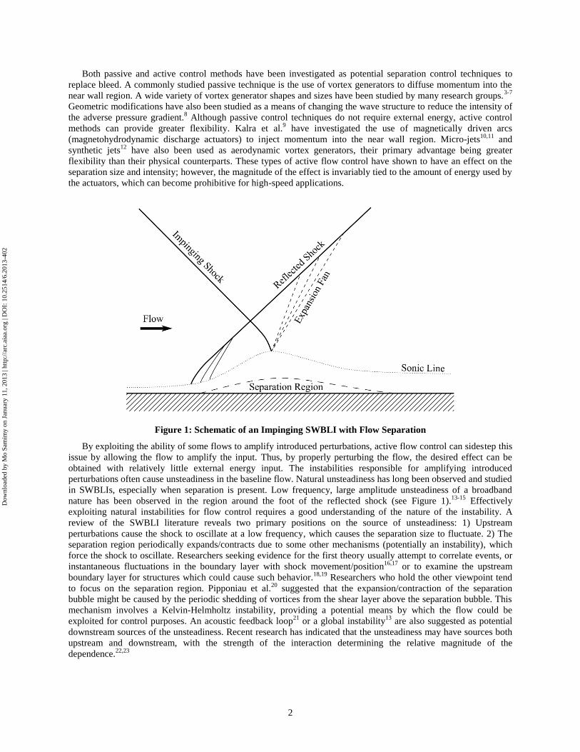
Figure 1: Schematic of an Impinging SWBLI with Flow Separation
By exploiting the ability of some flows to amplify introduced perturbations, active flow control can sidestep this
issue by allowing the flow to amplify the input. Thus, by properly perturbing the flow, the desired effect can be
obtained with relatively little external energy input. The instabilities responsible for amplifying introduced
perturbations often cause unsteadiness in the baseline flow. Natural unsteadiness has long been observed and studied
in SWBLIs, especially when separation is present. Low frequency, large amplitude unsteadiness of a broadband
nature has been observed in the region around the foot of the reflected shock (see Figure 1).13-15
Effectively
exploiting natural instabilities for flow control requires a good understanding of the nature of the instability. A
review of the SWBLI literature reveals two primary positions on the source of unsteadiness: 1) Upstream
perturbations cause the shock to oscillate at a low frequency, which causes the separation size to fluctuate. 2) The
separation region periodically expands/contracts due to some other mechanisms (potentially an instability), which
force the shock to oscillate. Researchers seeking evidence for the first theory usually attempt to correlate events, or
instantaneous fluctuations in the boundary layer with shock movement/position16,17
or to examine the upstream
boundary layer for structures which could cause such behavior.18,19
Researchers who hold the other viewpoint tend
to focus on the separation region. Pipponiau et al.20
suggested that the expansion/contraction of the separation
bubble might be caused by the periodic shedding of vortices from the shear layer above the separation bubble. This
mechanism involves a Kelvin-Helmholtz instability, providing a potential means by which the flow could be
exploited for control purposes. An acoustic feedback loop21
or a global instability13
are also suggested as potential
downstream sources of the unsteadiness. Recent research has indicated that the unsteadiness may have sources both
upstream and downstream, with the strength of the interaction determining the relative magnitude of the
dependence.22,23
Dow
nloa
ded
by M
o Sa
mim
y on
Jan
uary
11,
201
3 | h
ttp://
arc.
aiaa
.org
| D
OI:
10.
2514
/6.2
013-
402

3
Localized Arc Filament Plasma Actuators (LAFPAs) were developed at The Ohio State University as a means to
introduce strong, tailored, high frequency perturbations to flows.24-26
They have been explored as a noise mitigation
and mixing enhancement technique in high-speed, high Reynolds number jets25,26
and recently for cavity flow
control.27
The flexibility of the LAFPAs also enables them to be used for feedback control.28
The possibility of
natural instabilities within SWBLIs which modify the separation size suggested that the ability of LAFPAs to
mitigate SWBLI induced separation should be investigated. Titchener et al.29
has observed that a single oblique
SWBLI, or “unit problem” (see Figure 1), is probably not an adequate model of a supersonic inlet, however the goal
of this research is to fundamentally explore the ability of LAFPAs to modify such a flow; therefore a unit problem
was deemed an appropriate environment in which to conduct initial testing of the LAFPAs.
The separation control authority of the LAFPAs had previously shown to hold promise in a preliminary work.30
The test facility was therefore improved and enlarged, and more extensive measurements were conducted.31
Further
experiments concluded that when the LAFPAs are located upstream of the interaction region their primary effect is
to shift the reflected shock upstream.32
It was suggested that the actuators were merely heating the incoming
boundary layer, thereby degrading and enlarging the separation, displacing the reflected shock. This paper seeks to
confirm this hypothesis through further analysis and experiment.
II. Experimental Methodology
A. Physical Arrangement
The facility in which the LAFPAs are tested models a single, oblique, impinging SWBLI. It is a blow-down
facility with a freestream Mach number of 2.33. The air for the facility is compressed, dried and stored in two large
tanks (~36 m3 total volume). The air supply is sufficient to run continuously, however other factors (tunnel
temperature, oil buildup during PIV, etc.) typically limit a run to 1 to 2 minutes. The test section is rectangular, 76.2
mm by 72.9 mm, and the stagnation temperature is approximately ambient. There is optical access to the test section
through two nominally 76 mm high by 250 mm long fused quartz windows. A narrow window in the test section
ceiling allows for a laser sheet along the tunnel centerline. The primary shock is generated by a 10° compression
ramp on the tunnel ceiling. The shock generator can be placed at three distinct streamwise locations, allowing the
effective location of the LAFPAs to be varied. Figure 2 depicts the test section used in this work. It also shows the
length scale, L, which is the nominal interaction length, and the normalized streamwise coordinate (X*) used in this
paper. For more details regarding the facility please refer to Webb et al.31
Figure 2: Test Section Schematic with Compression Ramp Model Installed; Inset Shows Spanwise
Arrangement of the LAFPAs
The LAFPAs consist of two tungsten electrodes with the tips flush to the tunnel surface. The electrodes are 1
mm in diameter, and are in a groove 0.5 mm deep. The groove serves to shield and stabilize the arc after breakdown.
Previous research has shown the groove to have a negligible effect on the control authority of the LAFPAs over
Dow
nloa
ded
by M
o Sa
mim
y on
Jan
uary
11,
201
3 | h
ttp://
arc.
aiaa
.org
| D
OI:
10.
2514
/6.2
013-
402

4
jets.33
The electrode spacing is 3.5 mm (center-to-center) and 5.2 mm between actuators. As shown in the inset in
Figure 2, there are eight actuators arranged in a spanwise row across the facility. For this work, the streamwise
location of the row was varied throughout the upstream region of the interaction. The electrodes are also arranged in
the spanwise line, so that the flow direction is across the gap between electrodes. Perturbations are generated by the
formation of an arc between the electrodes, and the subsequent heat release. The power supply used in this work was
developed at the Gas Dynamics and Turbulence Laboratory and allows discrete perturbations (breakdown, arc
formation, then shutdown) to be generated continuously at frequencies up to 200 kHz.24
The duty cycle (percent of
the period for which the actuator is arcing) is variable up to 50%. Due to the goal of exploiting the flow to amplify
the perturbations, rather than brute forcing of the flow, the actuators have a relatively low power deposition.
Breakdown power is large, but the extremely short duration of the process results in a negligible contribution to the
average power. The instantaneous power of the steady state arc is approximately 100 W, and the average power
depends on the duty cycle. For the majority of this work the duty cycle was 50%, yielding an average power of 50
W per actuator, or 400 W overall. This is approximately 0.13% of the flow power (P = ∞AU∞3).
B. Flow Diagnostics
Schlieren imaging was used as a fast and easy diagnostic for observing the flow density gradients, particularly the
wave structure. This allowed the baseline flow to be confirmed as the desire flow. The interaction length (“L” in
Figure 2) can also be measured from the schlieren images, and any changes in the wave structure due to actuation
can be observed.
Particle Image Velocimetry (PIV) was performed using two distinct configurations. The first was two-
component PIV on a streamwise-vertical plane along the tunnel centerline (subsequently referred to as “streamwise
PIV”). This yielded quantitative data regarding the LAFPAs’ ability to modify the centerline interaction. The second
configuration was stereoscopic PIV on a streamwise-spanwise oriented plane located 2 mm above the floor
(subsequently referred to as “horizontal PIV”). Figure 3 is a schematic of both PIV configurations. Only preliminary
results have been collected in this configuration, however it allows the spanwise variation in the interaction to be
examined as well as a better view of the separation region. Olive oil seed particles were introduced into the flow in
the stagnation chamber using two particle atomizers in parallel. This setup yielded particles with a nominal diameter
slightly less than 1 m. The PIV data for both configurations were acquired using the commercially available DaVis
7.2 PIV software. The streamwise PIV data were collected using a single LaVision Imager Pro X camera; the
horizontal PIV used two LaVision Imager Pro cameras. The laser was a Spectra Physics Quanta-Ray PIV 400 laser.
DaVis was used to correlate and post-process the data, which were then transferred to MATLAB for analysis and
reduction.
(a)
(b)
Figure 3: PIV Physical Configuration, a) Streamwise PIV, b) Horizontal PIV
Dow
nloa
ded
by M
o Sa
mim
y on
Jan
uary
11,
201
3 | h
ttp://
arc.
aiaa
.org
| D
OI:
10.
2514
/6.2
013-
402

5
III. Results and Discussion
A. Baseline Flow
The baseline flow of this facility has been extensively studied and found to conform well to the characteristics of
SWBLIs documented in literature. Figure 4 is a long-exposure schlieren image of the baseline flow. The two dark
lines are the incident and reflected shock waves. There are also several weak shocks present due to seams in the
facility, which have been confirmed (with PIV) to have negligible effect on the flow. The interaction length, as
defined in Figure 2, has been measured to be 39 mm. This length, in addition to being used to normalize streamwise
locations, was also used to normalize the frequency of the low-frequency unsteadiness of the interaction region and
the forcing frequencies. The unsteadiness frequency (and therefore potentially the most amplified frequencies) has
been shown to vary between approximately 0.03 and 0.5 when normalized by the freestream velocity and the
interaction length.15
The normalized low frequency associated with the reflected shock foot is St = 0.03.
Figure 4: Baseline Long-Exposure Schlieren Image
As it was previously postulated that the LAFPAs are merely affecting the SWBLI through the upstream
boundary layer32
, and the nature of interaction depends on the state of the boundary layer,(pp. 28 34
) characterization
of the upstream boundary layer is important. Streamwise PIV data were used to document the upstream boundary
layer, and Table 1 details the results. The boundary layer thickness () is based on the 0.99U∞ criterion. The integral
quantities are calculated both in the compressible and incompressible manner (subscript “i” denotes
“incompressible”). The density profile for the compressible quantities was estimated using the method proposed by
Maise and McDonald.35
Although these quantities may more accurately reflect the flow characteristics, the
incompressible quantities are more widely used, and thus more easily comparable to literature.(pp. 21 34)
Reynolds
number based on several length scales is tabulated, but the most commonly used is that based on the incompressible
momentum thickness.
Table 1: Upstream Boundary Layer Properties
M∞ u∞ (m/s) (mm) i* (mm) i (mm) Hi
*
(mm)
(mm) H
2.33 559 5.35 1.40 0.78 1.79 2.28 0.53 4.27
Re (1/m) Re Re Rei
35.7·106 191,000 18,900 27,900
More information regarding the baseline flow can be obtained from Webb et al.32
In particular it is demonstrated
that the incoming boundary layer is turbulent, the boundary layer separates, and the unsteadiness of the interaction is
consistent with that observed in literature.
B. LAFPA Control Authority
The most obvious effect of the LAFPAs when located in and around the upstream end of the interaction is the
displacement of the reflected shock upstream.32
This effect is most readily observed from velocity difference maps
Dow
nloa
ded
by M
o Sa
mim
y on
Jan
uary
11,
201
3 | h
ttp://
arc.
aiaa
.org
| D
OI:
10.
2514
/6.2
013-
402

6
constructed from streamwise PIV data by subtracting the baseline vector field from the forced vector field. The
LAFPAs were initially located at Xa* = -0.83, and operated in-phase at a frequency of StF = 0.03. The results are
shown in Figure 5. The reflected shock clearly moves upstream and the interaction region also moves slightly
upstream. The reflected shock movement is clearly visible in the vertical velocity difference maps as a dark line (not
to be mistaken for the shock thickness), therefore the streamwise velocity maps will be omitted.
Figure 5: Ensemble-Averaged Velocity Difference Fields with Forcing Strouhal Number StF = 0.03
In order to further investigate the LAFPAs’ ability to displace the reflected shock, phase-locked PIV data were
acquired. DaVis has the capability to synchronize acquisition with an external trigger signal. This feature was used
to acquire the data at eight evenly spaced intervals throughout the LAFPAs’ forcing period, providing insight into
the interaction’s phase-averaged behavior. The velocity difference map for each of these phases is shown in Figure
6. The phase is denoted by its angle, where 0° is when the LAFPAs begin arcing (Figure 6a), and 180° is when they
cease arcing (Figure 6e). Examining Figure 6 shows that the reflected shock appears to travel upstream while the
LAFPAs are arcing, and relax toward the baseline case after the arcing ceases. At this frequency, the shock does not
appear to have sufficient time to relax completely back to the baseline. This would appear to support the previously
hypothesized mechanism which regards the LAFPAs’ heat addition as the primary control mechanism.
a) Phase 1 (0)
b) Phase 2 (45)
Dow
nloa
ded
by M
o Sa
mim
y on
Jan
uary
11,
201
3 | h
ttp://
arc.
aiaa
.org
| D
OI:
10.
2514
/6.2
013-
402

7
c) Phase 3 (90)
d) Phase 4 (135)
e) Phase 5 (180)
f) Phase 6 (225)
g) Phase 7 (270)
h) Phase 8 (315)
Figure 6: Ensemble-Averaged Velocity Difference Fields for StF = 0.03 and DC = 50% Phase Sweep
Dow
nloa
ded
by M
o Sa
mim
y on
Jan
uary
11,
201
3 | h
ttp://
arc.
aiaa
.org
| D
OI:
10.
2514
/6.2
013-
402

8
If the primary control mechanism is through heating, then changing the duty cycle (time averaged power
deposition) should have a strong effect on the reflected shock displacement. The actuators were therefore operated at
duty cycles of 10%, 30%, and 50%, and the results are shown in Figure 7. As will be discussed later, it was
determined that the streamwise location of the LAFPAs had a negligible effect on their control authority, therefore
the LAFPAs were located at Xa* = -0.96 for these experiments. The frequency of actuation was maintained at StF =
0.03. Although eight phases were collected for each case, only two are displayed: the phase at which maximum
shock displacement occurs (“Max. Displacement”) and that at which minimum shock displacement occurs (“Max.
Relaxation”). The reflected shock displacement is seen to increase with increasing duty cycle for both phases. This
supports the hypothesis that the LAFPAs exert their control authority through heating. A higher duty cycle indicates
that the LAFPAs are arcing for a greater percentage of the period, which not only increases the amount of time the
boundary layer is being heated, but also decreases the time in which the shock relaxes back to the baseline.
a) DC = 10%, Max. Displacement
b) DC = 10%, Max. Relaxation
c) DC = 30%, Max. Displacement
d) DC = 30%, Max. Relaxation
Dow
nloa
ded
by M
o Sa
mim
y on
Jan
uary
11,
201
3 | h
ttp://
arc.
aiaa
.org
| D
OI:
10.
2514
/6.2
013-
402

9
e) DC = 50%, Max. Displacement
f) DC = 50%, Max. Relaxation
Figure 7: Ensemble Averaged Velocity Difference Fields for a Variety of Duty Cycles
In addition to examining the dependence of control authority on duty cycle, the effects of actuator location and
operating frequency were investigated. It was found that within the region tested (-1.09 X* -0.77), the location
had a negligible effect on control authority. Instabilities often have receptivity regions, where introduced
perturbations are most efficiently amplified. Thus, the lack of location dependence, near the expected receptivity
region, coupled with the finding that there is no frequency at which effectiveness was maximized seems to indicate
that the LAFPAs are not controlling the flow by manipulating an instability associated with the unsteadiness near the
upstream end of the interaction. The nature of the dependence of the actuator’s control authority on frequency also
suggests that the time spent arcing, and perhaps more importantly the available relaxation time, is the important
factor in determining the mean displacement amount. The complete results of the parameter sweep are published in
Webb et al.32
C. Further Investigation of Flow Control Mechanism
Previously the LAFPAs have manipulated natural instabilities to achieve control authority25,36
however, that does
not appear to be the case for this configuration. This can be observed from the manner in which the LAFPAs control
authority depends on location and frequency. Evidence from the phase and duty cycles sweeps suggests that the
LAFPAs are simply heating the upstream boundary layer. Jaunet et al.37
have observed that the reflected shock is
displaced upstream if the surface beneath the incoming boundary layer is heated. The change in density was
suggested as a potential reason for this displacement. Reducing the incoming boundary layer density alters the mass
balance within the separation region causing the bubble to expand.38
Their observed displacement is similar to what
has been observed in this work; however, the magnitude of the effect is greater in their case. Boundary layer heating
also accounts for the lack of control authority dependence on location (as long as the LAFPAs remain upstream of
the interaction). As previously mentioned, both the effects of frequency and duty cycle trends are consistent with a
heating mechanism. This hypothesis seems to be supported by observed trends in the current work, however, the
relatively small power deposition by the LAFPAs, estimated to be almost two orders of magnitude less than that
used by Jaunet et al.37
, makes the generation of such a substantial effect a dubious proposition. It is conceivable,
however, that the high power density of the LAFPAs could enable them to produce the observed effect.
The large effect, relative to the size of the power input, prompted a more thorough investigation, despite clear
evidence of a heating mechanism. Souverein38
addresses the relationship between the displacement thickness, and
the separation length. Although the presented relationships are somewhat complex, when all other parameters are
held constant (as in this work), the relationship reduces to a proportionality between the displacement thickness and
the separation length. This result is intuitive: a degraded turbulent boundary layer is less resistant to separation;
therefore, the separation size will increase. In addition, since the actuators heat the flow, the upstream travelling
pressure waves (in the subsonic region of the boundary layer) will travel upstream faster, causing the separation to
expand upstream, thereby pushing the reflected shock upstream.
Dow
nloa
ded
by M
o Sa
mim
y on
Jan
uary
11,
201
3 | h
ttp://
arc.
aiaa
.org
| D
OI:
10.
2514
/6.2
013-
402

10
The results make sense; the question is merely one of scale: Can the LAFPAs produce a sufficient degradation to
generate the observed displacement? For the initial test case (StF = 0.03), the mean shock movement was
approximately 4 mm (75% of the boundary layer thickness upstream of the interaction). The overall interaction
length was measured to be 39 mm (see Figure 4) giving an increase of 10%. Assuming the shock movement
(interaction length change) is caused by a separation expansion, the LAFPAs must be able to increase the incoming
boundary layer displacement thickness by at least 10%. An initial, simplified analysis was conducted to determine if
this is possible. The LAFPAs were assumed to operate strictly through Joule heating (increasing the total
temperature). Quasi-one-dimensional, adiabatic, perfect gas flow was assumed, and the wall normal pressure
gradient was assumed zero. The total temperature profile downstream of the LAFPAs was estimated using a basic
knowledge of heat transfer and the known power deposition. The total temperature profile allows the density profile
to be calculated, which, in combination with baseline velocity profile obtained through PIV, can be used to calculate
the forced displacement thickness. Note that for both the baseline and forced displacement thicknesses, the
compressible values were used. The effects of compressibility on density were estimated using the method proposed
by Maise and McDonald.35
Using the proportionality relation indicates that the LAFPAs can only increase the
interaction length by 1.9 mm if they operate strictly through Joule heating, or they must output 0.84 kW to generate
the observed effect. Comparing this to the actual 0.4 kW means that the LAFPAs cannot generate the observed
effect through Joule heating alone.
Although Joule heating alone is insufficient to generate the observed effect, the LAFPAs also affect the velocity
profile. Kleinman et al.39
performed two-dimensional simulations of the LAFPAs in jet flow. These simulations
found that significant mass injection from the groove takes place. Although expansion along the groove prevents the
injection from being significant, a small amount of injection would still act to generate a wake, degrading the
velocity profile. Hahn et al.33
show that the groove has an insignificant effect on the LAFPAs’ control authority,
supporting the conclusion that injection has a minimal effect in this work.
It is however unlikely that the LAFPAs have no effect on the boundary layer velocity profile. This was one of
the major assumptions of the earlier simplified analysis. In order to eliminate this assumption, experiments were
conducted in which the undisturbed boundary layer was forced and velocity profiles were collected using PIV data.
Two forcing frequencies: f = 1 kHz and 20 kHz were used. The duty cycle for both frequencies was 50%. Due to
data corruption by the glow of the LAFPAs velocity profiles from ~14 downstream were scaled to determine the
effect of the LAFPAs on the velocity profile. It was unclear whether the displacement thickness or boundary layer
thickness was the proper scaling parameter in this case. Therefore, both were used, and the resulting differences
found to be negligible. When the experimental profiles were used, it was found that the estimated temperature
profile necessary to generate the observed effect for the f = 1 kHz case required 0.4 kW, and for the f = 20 kHz, 0.38
kW. Thus this analysis showed that the LAFPAs can increase the displacement thickness sufficiently to result in the
observed changes, further confirming the hypothesized mechanism.
The proposed control mechanism is that the actuators degrade the upstream boundary layer, resulting in an
increased separation size, which displaces the reflected shock upstream. It has been shown that the LAFPAs are
capable of increasing the displacement thickness sufficiently to accomplish the observed shock displacement. In
order to further confirm this mechanism, preliminary horizontal PIV measurements were collected for baseline and
forced cases, and the footprint of the separation region was examined. Figure 8 shows the streamwise velocity maps
of the baseline and forced cases. Although the plane is only 2 mm from the surface, the separation region vertical
dimension is small; therefore no mean reversed flow is detected at this location. However, the separation region is
visible because of the shear layer over it, which is clearly captured in the measurements. An examination of the
“separation” region shows that the actuators do enlarge the separation, resulting in the reflected shock being pushed
upstream. This result can also be confirmed from the vertical velocity maps (not shown). It should be noted that the
low velocity lines present in Figure 8 are merely due to plasma glow (║ on the left) and laser scatter (╞ on the right).
Dow
nloa
ded
by M
o Sa
mim
y on
Jan
uary
11,
201
3 | h
ttp://
arc.
aiaa
.org
| D
OI:
10.
2514
/6.2
013-
402

11
Figure 8: Baseline and Forced Horizontal PIV Streamwise Velocity Maps
The results show that the LAFPAs are most likely controlling the interaction through heating the boundary layer,
which enlarges the separation, displacing the shock. Thus the LAFPAs are not manipulating natural instabilities in
this configuration. However, in other configurations, namely with the LAFPAs downstream where they cannot
modify the incoming boundary layer, they may be able to manipulate instabilities associated with the SWBLI.
Increasing our understanding of the SWBLI dynamics is essential for optimally manipulating instabilities. One
aspect of the dynamics, which has only recently been recognized as important is the interaction between the corner
flows and the centerline. The preliminary PIV measurements are not high quality, and data near the walls is suspect.
However these measurements are being improved, and when the quality is sufficient, they will be able to provide
substantial data about how the LAFPAs affect the centerline/corners and how these two interplay. Of especial
interest is to see how forcing with just the centerline, or just the sidewall actuators causes these regions to interact.
IV. Conclusions
The LAFPAs’ control over a Mach 2.3, impinging, oblique SWBLI with a turbulent incoming boundary layer (Re
= 27,900) has been investigated. The baseline flow has been observed to be consistent with what is described in
literature.32
The LAFPAs were observed to displace the reflected shock upstream by approximately one boundary
layer thickness (~ 5 mm). The results of phase-locked PIV measurements, as well as a parametric study led to the
hypothesis that the LAFPAs were controlling the flow by heating the upstream boundary layer. Both the phase-
locked PIV and the duty-cycle study suggested that the mechanism was dependent on the actuators arcing duration,
rather than the frequency of actuation. The location and frequency studies lent weight to this conclusion by
demonstrating that the LAPFAs were not controlling the flow through the manipulation of natural instabilities.
Forcing the undisturbed boundary layer, combined with further analysis has confirmed that the LAFPAs can
generate the observed effect through boundary layer degradation. Horizontal PIV measurements confirming that the
separation expands when the flow is forced further reinforces this conclusion. Therefore, it is concluded that in this
configuration, the LAFPAs exert their control authority by a modification of the upstream boundary layer, primarily
through heat addition. Future horizontal PIV measurements will be used to gain an improved understanding of the
corner flow dynamics. Additional physical configurations (namely with the LAFPAs located in the downstream
portion of the interaction) will also be examined to ascertain the LAFPA’s effects in that arrangement.
Acknowledgments
The support of this work by the Air Force Office of Scientific Research (Dr. John Schmisseur) is gratefully
acknowledged.
Dow
nloa
ded
by M
o Sa
mim
y on
Jan
uary
11,
201
3 | h
ttp://
arc.
aiaa
.org
| D
OI:
10.
2514
/6.2
013-
402
12
References 1 Syberg, J. and J. L. Koncsek, "Experimental Evaluation of an Analytically Derived Bleed System for a Supersonic
Inlet," Journal of Aircraft Vol. 13, No. 10 (1976): 792-97. 2 Baruzzini, D., "An Industry Perspective on the Role of Bleed in High-Speed Inlet Design Process," (2012): Private
Communication 3 Shahneh, A. and F. Motallebi, "Effect of Submerged Vortex Generators on Shock-Induced Separation in Transonic
Flow," Journal of Aircraft Vol. 46, No. 3 (2009): 856-63. 4 Anderson, B. H., J. Tinapple, and L. Surber, "Optimal Control of Shock Wave Turbulent Boundary Layer
Interactions Using Micro-Array Actuation," 3rd AIAA Flow Control Conference: 2006-3197. 5 Babinsky, H., Y. Li, and C. P. Ford, "Microramp Control of Supersonic Oblique Shock-Wave/Boundary-Layer
Interactions," AIAA Journal Vol. 47, No. 3 (2009): 668-75. 6 Lee, S., M. Goettke, E. Loth, J. Tinapple, and J. Benek, "Microramps Upstream of an Oblique-Shock/Boundary-
Layer Interaction," AIAA Journal Vol. 48, No. 1 (2010): 104-18. 7 Lee, S., E. Loth, and H. Babinsky, "Normal Shock Boundary Layer Control with Various Vortex Generator
Geometries," AIAA 5th Flow Control Conference: 2010-4254. 8 Babinsky, H. and H. Ogawa, "Sbli Control for Wings and Inlets," Shock Waves Vol. 18, No. 2 (2008): 89-96.
9 Kalra, C. S., S. H. Zaidi, R. B. Miles, and S. O. Macheret, "Shockwave-Turbulent Boundary Layer Interaction
Control Using Magnetically Driven Surface Discharges," Experiments in Fluids Vol. 50 (2011): 547-59. 10
Solomon, J. T., R. Kumar, and F. S. Alvi, "High-Bandwidth Pulsed Microactuators for High-Speed Flow Control,"
AIAA Journal Vol. 48, No. 10 (2010): 2386-96. 11
Souverein, L. J. and J.-F. Debiève, "Effect of Air Jet Vortex Generators on a Shock Wave Boundary Layer
Interaction," Experiments in Fluids Vol. 49 (2010): 1053-64. 12
Narayanaswamy, V., L. Raja, and N. Clemens, "Characterization of a High-Frequency Pulsed-Plasma Jet Actuator
for Supersonic Flow Control," AIAA Journal Vol. 48, No. 2 (2010): 297-305. 13
Touber, E. and N. D. Sandham, "Large-Eddy Simulation of Low-Frequency Unsteadiness in a Turbulent Shock-
Induced Separation Bubble," Theoretical and Computational Fluid Dynamics Vol. 23 (2009): 79-107. 14
Dolling, D. and L. Brusniak, "Separation Shock Motion in Fin, Cylinder, and Compression Ramp-Induced
Turbulent Interactions," AIAA Journal Vol. 27, No. 6 (1989): 734-42. 15
Dupont, P., C. Haddad, and J. F. Debiève, "Space and Time Organization in a Shock-Induced Separated Boundary
Layer," Journal of Fluid Mechanics Vol. 559 (2006): 255-77. 16
Andreopoulos, J. and K. C. Muck, "Some New Aspects of the Shock-Wave/Boundary-Layer Interaction in
Compression-Ramp Flows," Journal of Fluid Mechanics Vol. 180 (1987): 405-28. 17
Beresh, S. J., N. T. Clemens, and D. S. Dolling, "Relationship between Upstream Turbulent Boundary-Layer
Velocity Fluctuations and Separation Shock Unsteadiness," AIAA Journal Vol. 40, No. 12 (2002): 2412-22. 18
Ganapathisubramani, B., N. Clemens, and D. Dolling, "Low-Frequency Dynamics of Shock-Induced Separation in
a Compression Ramp Interaction," Journal of Fluid Mechanics Vol. 636 (2009): 397-425. 19
Beresh, S. J., J. F. Henfling, R. W. Spillers, and B. O. M. Pruett, "Very-Large-Scale Coherent Structures in the
Wall Pressure Field beneath a Supersonic Turbulent Boundary Layer," 49th AIAA Aerospace Sciences
Meeting: 2011-746. 20
Piponniau, S., J. Dussauge, J. Debieve, and P. Dupont, "A Simple Model for Low-Frequency Unsteadiness in
Shock-Induced Separation," Journal of Fluid Mechanics Vol. 629 (2009): 87-108. 21
Pirozzoli, S. and F. Grasso, "Direct Numerical Simulation of Impinging Shock Wave/Turbulent Boundary Layer
Interaction at M=2.25," Physics of Fluids A Vol. 18 (2006): 1-17. 22
Narayanaswamy, V., "Investigation of a Pulsed-Plasma Jet for Separation Shock/Boundary Layer Interaction
Control," Ph.D. Thesis. University of Texas at Austin, (2010): Print. 23
Touber, E. and N. D. Sandham, "Low-Order Stochastic Modelling of Low-Frequency Motions in Reflected
Shock-Wave/Boundary-Layer Interactions," Journal of Fluid Mechanics Vol. 671 (2011): 417-65. 24
Utkin, Y. G., S. Keshav, J.-H. Kim, J. Kastner, I. V. Adamovich, and M. Samimy, "Development and Use of
Localized Arc Filament Plasma Actuators for High-Speed Flow Control," Journal of Physics D: Applied
Physics Vol. 40, No. 3 (2007): 685-94. 25
Samimy, M., J.-H. Kim, J. Kastner, I. Adamovich, and Y. Utkin, "Active Control of High-Speed and High-
Reynolds-Number Jets Using Plasma Actuators," Journal of Fluid Mechanics Vol. 578, No. 1 (2007): 305-
30. 26
Samimy, M., J.-H. Kim, J. Kastner, I. Adamovich, and Y. Utkin, "Active Control of a Mach 0.9 Jet for Noise
Mitigation Using Plasma Actuators," AIAA Journal Vol. 45, No. 4 (2007): 890-901.
Dow
nloa
ded
by M
o Sa
mim
y on
Jan
uary
11,
201
3 | h
ttp://
arc.
aiaa
.org
| D
OI:
10.
2514
/6.2
013-
402

13
27 Yugulis, K., J. Gregory, and M. Samimy, "Control of High Subsonic Cavity Flow Using Plasma Actuators," 51st
AIAA Aerospace Sciences Meeting: Forthcoming. 28
Sinha, A., K. Kim, J. Kim, A. Serrani, and M. Samimy, "Extremizing Feedback Control of a High-Speed and High
Reynolds Number Jet," AIAA Journal Vol. 48, No. 2 (2010): 387-99. 29
Titchener, N., H. Babinsky, and E. Loth, "Can Fundamental Shock-Wave/Boundary-Layer Interaction Research
Be Relevant to Inlet Aerodynamics?," 50th AIAA Aerospace Sciences Meeting: AIAA 2012-0017. 30
Caraballo, E., N. Webb, J. Little, J.-H. Kim, and M. Samimy, "Supersonic Inlet Flow Control Using Plasma
Actuators," 47th AIAA Aerospace Sciences Meeting: 2009-924. 31
Webb, N., C. Clifford, and M. Samimy, "Preliminary Results on Shock Wave/Boundary Layer Interaction Control
Using Localized Arc Filament Plasma Actuators," 41st AIAA Fluid Dynamics Conference: 2011-3426. 32
Webb, N., C. Clifford, and M. Samimy, "Control of Oblique Shock Wave-Boundary Layer Interactions Using
Plasma Actuators," 6th AIAA Flow Control Conference: 2012-2810. 33
Hahn, C., M. Kearney-Fischer, and M. Samimy, "On Factors Influencing Arc Filament Plasma Actuator
Performance in Control of High Speed Jets," Experiments in Fluids Vol. 37, No. 5 (2011). 34
Babinsky, H. and J. K. Harvey, Shock Wave-Boundary-Layer Interactions. New York, New York: Cambridge
University Press, 2011. Print. 35
Maise, G. and H. McDonald, "Mixing Length and Kinematic Eddy Viscosity in a Compressible Boundary Layer,"
AIAA Journal Vol. 6, No. 1 (1968): 73-80. 36
Samimy, M., M. Kearney-Fischer, J.-H. Kim, and A. Sinha, "High-Speed and High-Reynolds-Number Jet Control
Using Localized Arc Filament Plasma Actuators," Journal of Propulsion and Power Vol. 28, No. 2 (2012). 37
Jaunet, V., J. F. Debiève, and P. Dupont, "Experimental Investigation of an Oblique Shock Reflection with
Separation over a Heated Wall," 50th AIAA Aerospace Sciences Meeting: AIAA 2012-1095. 38
Souverein, L., "On the Scaling and Unsteadiness of Shock Induced Separation." IUSTI, (2010): Print. 39
Kleinman, R. R., D. J. Bodony, and J. B. Freund, "Numerical Modeling of Plasma Actuators in High Speed Jets,"
AIAA/CEAS 15th Aeroacoustics Conference: 2009-3190.
Dow
nloa
ded
by M
o Sa
mim
y on
Jan
uary
11,
201
3 | h
ttp://
arc.
aiaa
.org
| D
OI:
10.
2514
/6.2
013-
402