an overview of the small engine … usaavscom technical memorandum 88796 technical report 86-c-23...
TRANSCRIPT

NASA USAAVSCOMTechnical Memorandum 88796 Technical Report 86-C-23AIAA-86-1542
: NASA-TM-88796
lq _(oO,gg_ l lff"
An Overview of the Small EngineComponent Technology (SECT) Studies
M.R. Vanco, W.T. Wintucky, and R.W. NiedzwieckiLewis Research Center ].]_Ot_ _] _i_Cleveland, Ohio
LI_nRARY,NASApZ,',,'_,,_LO_d,yJ.F,_',U_A
Prepared for the22nd Joint Propulsion Conferencecosponsored by the AIAA, ASME, SAE, and ASEE
' Huntsville, Alabama, June 16-18, 1986
https://ntrs.nasa.gov/search.jsp?R=19860022115 2018-08-31T08:41:58+00:00Z


DISPLAY 21/6/1
86N31587_.'# ISSUE 23 PAGE 3558 CATEGORY 7 RPT#: NASA-TM-88796
E-3131 NAS 1.15:88'796 USAAVSCOM-TR-86-C-E!3 AIAA-86-154_'2 86/_'_6/00 20PAGES UNCLASSIFIED DOCUMENT
UTTI..: An oveFview of" the Small Engine Component Technology (SECT) studiesAUTH: A/VANCO, M. R. ; B/WINTUCKY._ W. T. ; C!NIEDZWIECKI, R. W.
CORP: Natior_al Aeronautics and Space Adminis'tratior_. Lewis Research Center,C1 evel arid., Ohio.
SAP: Avail: NTIS HC A02iMF AOI
CIO: UNITED STATES Prese'nted at the E_2nd Joi_Tt Propulsion Conference..
Huntsville: Ala., 16-18 Jun. 1986; cosponsored by AIAA, ASME, SAE, and 'ASEE ',
MAJS: /_.AIRCRAFT ENGINES/_.COST REDUCTION/+'.-ENGINE DESIGN/e_..ENGINE PARTSi_:GAS
TURBINE ENGINESi_(-REGENERATORSi.mTECHNOLOGY ASSESSMEN]"/_.TURBOFAN ENGINESi.I_"TLIF_'BOI-'ROP ENGINES
MINS: / CERAMICS/ COMMERCIAL AIRCRAFT/ CRUISE MISSILES/ FUEL CONSUMF'TIONiOPERATING COSTS/ PASSENGER AIRCRAFT/ TILT ROTOR AIRCRAF'T
ABA : Authori

IL .

AIAA-86-1542AnOverviewoftheSmallEngineComponentTechnology(SECT)StudiesM.R.Vanco,W.T.Wintucky,andR.W.Niedzwiecki,NASALewisResearchCenter,Cleveland,OH
AIAAIASMEISAEIASEE22ndJointPropulsionConference,
June16-18,1986/Huntsville,Alabama
Forpermissiontocopyorrepublish,contacttheAmericanInstituteof AeronauticsandAstronautics
1633Broadway,NewYork,NY10019 /_,1_ - 3J 5_7 _


AN OVERVIEWOF THE SMALLENGINECOMPONENTTECHNOLOGY(SECT) STUDIES
M.R. Vanco, W.T. Wintucky, and R.W. NiedwieckiNational Aeronautics and Space Administration
Lewis Research CenterCleveland, Ohio 44135
' Abstract To achieve these fuel savings, an aggressivesmall engine component technology program is
The objectives of the joint NASA/Army SECT required. The overall program approach is toStudies were to identify high payoff techno]o- evolve, evaluate and verify the needed advancedgies for year 2000 small gas turbine engine technology for gas turbine engines of 250 toapplications and to provide a technology plan 1000 horsepower suitable for use in rotorcraft,for guiding future research and technology general aviation and commuter aircraft, andefforts applicable to rotorcraft, commuter and cruise missiles. Most of the technology isgeneral aviation aircraft and cruise missiles, common to all of the applications. The programCompetitive contracts were awarded to Allison, consists of: i. system studies and technologyAVCO Lycoming, Garrett, Teledyne CAE and assessment;2. discipline research and technol-Williams International. This paper presents an ogy; and 3. component research and technology.overview of the contractors study efforts for The first step in the program was a study effortthe commuter, rotorcraft, cruise missile, and to identify high payoff technologies for yearAPU applications with engines in the 250 to 2000 small gas turbine engine applications,and1,000 horsepower size range. Reference air- provide a technology plan for guiding futurecraft, missions and engines were selected, research and technology efforts. To completeAdvanced engine configurations and cycles with this first step, competitive contracts wereprojected year 2000 component technologieswere awarded to Allison Gas Turbine Division - Gen-evaluated and compared with a reference engine eral Motors Corporation,AVCO Lycoming Textron,selected by the contractor. For typical commu- Garrett Turbine Engine Co., Teledyne CAE andter and rotorcraft applications, fuel savings Williams International. These contracts wereof 22 percent to 42 percent can be attained, joint programs sponsored by NASA Lewis ResearchFor $1/gallon and _2/gaIIon fuel, reductions in Center and the U.S. Army Aviation Research anddirect operating cost range from 6 percent to Technology Activity - Propulsion Directorate.16 percent and from 11 percent to 17 percent This paper presents an overview of the contrac-respectively. For SUbsonic strategic cruise tor Study efforts for the commuter, rotorcraft,missile applications, fuel savings of 38 per- cruise missile and APU applications.cent to 54 percent can be achieved which allows
35 percent to 60 percent increase in mission Program Scoperange and life cycle cost reductions of 40percent to 56 percent. High payoff technolo- Each contractor study effort consisted of:gies have been identifiedfor all applications, selection of mission evaluation procedures and
assumptions; evaluation of engine configura-Introduction tions and cycles, engine/aircraft mission
analysis to determine figures-of-merit to rankSmall gas turbine engine performancein the 250 technologies; and preparation of a technologyto 1,000 horsepower size range is significantly plan to guide research and technologyverifica-lower than that of large engines. The major tion, component and systems research and tech-reasons are that: I. component efficiencies nology programs.for small engines are from 8 to 10 percentagepoints lower than those of large engines; and Selection of Evaluation Procedures and Assump-2. small engine cycle pressure ratios and tur- tionsbine inlet temperatures are considerably lowerthan large engines. Analytical design tech- Each contractor selected one or more of theniques and manufacturing techniques of large following year 2000 small gas turbine engineengines are not directly transferableto small applications: high performance, high pressureengines. Current research on very small (100 ratio, high power/weightrotorcraft engine; lowhorsepower) gas turbine automotive engines and pressure ratio, low SFC regenerative commuter
" general studies of the application of this or rotorcraft engine; high power density, lowresearch to aircraft engines indicate that cer- SFC APU; or low cost, high performance cruiseamics and regenerative cycles also have the missile engine.potential for significant improvement in fuel
savings for aircraft gas turbine engines. With Reference aircraft, mission type, range, Machthe incorporation of ceramics, regenerative number capability, and passenger load factorscycles, and a significant improvementin compo- were selected. Aircraft and mission were based
nent performance, the year 2000 technology on projectionsfor year 2000. Aircraft weightssmall gas turbine engines could achieve fuel were reduced by use of composites. Companysavingson the order of 50 percent, marketing projectionswere used for the mission
profile, and number of passengers andlorpayload.
This paper is declared a work of the U.S. Government and is
not subject to copyright protection in the United States. 1

Current technology engines were used as base Contractor Resultsfor the reference engine. Engines were scaled
as required to meet the mission requirements. Summary of the results for Allison, AVCOReference engine performance, weight and cost Lycoming, Garrett, Teledyne CAE and Williamswere provided by the contractor as a basis for International individual SECT Studies is pre-comparison, sented in the following sections.
For the commuter, rotorcraft and APU applica- Allisontions, fuel prices of $1/gal and $2/gal were
used. This price range should bracket the pro- Allison selected a commercial rotorcraft appli-jected fuel cost increase anticipated for the cation. Details of the Allison SECT Study,year 2000 and will show the effects of doubling Contract NAS3-24542, are presented in Referencethe fuel cost. For cruise missile application, i. The eight passenger tilt rotor executive/JP-IO fuel was selected. Direct operating cost commercial aircraft shown in Figure 1 was(DOC) was selected as the figure-of-merit for selected as the reference aircraft. The mis-commuter, rotorcraft and APU applications sion for the twin turboshaftpowered tilt rotorwhereas, life cycle cost (LCC) was selected for aircraft is 350 nautical miles with cruisecruise missile. 1985 year dollars were used speed of 250 Knots at an altitude of 20,000for all cost calculations. All appropriate feet. Figure-of-merit is direct operatingproposed and existing noise and emission regu- cost. The reference engine, which is based onlations were examined or investigated for a current technology engine has TRIT of 2200°F,application to the selected configurations, pressure ratio of 14:1, and 1,000 shaft horse-
power (hp) at sea level static (SLS) take-off.Trade factors such as ADOCversus specific fuelconsumption (SFC), engine weight, and engine The following cycles were investigated: i.cost were used to evaluate engine configura- advanced simple cycle with pressure ratios totions and cycles. 25:1; 2. nonconcentric simple cycles with pres-
sure ratios to 40:1; 3. heat recovery cyclesEngine Configuration and Cycle Evalution with pressure ratios to 14:1; and 4. a cycle
using a wave pressure exchanger or a wave rotorAdvanced cycles investigated for each applica- in the high pressure system with pressuretion were: 1. advanced simple cycle with pres- ratios to 45:1. These cycles were investigatedsure ratios to 30:1; 2. nonconcentric cycles with TRIT in the range of 2200°F to 2800°F andwith pressure ratios from 30:1 to 45:1; and projected year 2000 component efficiencies.recuperator/regenerator cycles with pressure Uncooled and cooled turbines were examined.ratios to 14:1. For these advanced cycles, Because of the manufacturing problems associ-component efficiencies - 3 to 5 points above ated with a small size cooled turbine and thecurrent technology levels, and materials - significant performance penalty, cooled turbinesceramic/ceramic composites, single crystal, were eliminated. Turbine rotor inlet tempera-powder metallurgy PM materials for disks, were ture of 2800°F was selected based on the hotassumed. Turbine rotor inlet temperatures spot temperature capability of ceramic composite(TRIT) in the range of 2200°F to 3500:F were material and projected year 2000 comDustor pat-investigated along with cooled and uncooled tern factor less than .2. Regenerator andturbines. Trade factors mentioned above were recuperator effectiveness in the range of .6 toused tO select the best engine configura- .8 and pressure drops of 6 percent to 14 percenttion(s)/cycle(s), were considered. The optimum cycle parameters
for each advanced cycle considered are:Systems Performance Evaluation - Engine/AircraftMission Analysis Non- Wave
Concentric Concentric Recup. Regen. Rotor
Mission analyses were conducted to determine Pressure Ratio 25 30 14 10 38effects of advanced technology engines on sys-tem performance. Advanced technology engines TRIT, "F 2800 2800 2800 2800 2800
and reference engines were flown in aircraft Effectiveness .6 .7over the same mission. The advanced technology aPIP .1o .13
engine aircraft sizes were adjusted for engine LP Compressor Axial Axi-Centrif. - _iallsize effects and fuel consumption. Aircraft Centrif.technology was the same for both aircraft.Fuel burned, cost, and an appropriate opera- HP Compressor Centrif. Centrif. Axial/ Axial/ Wave
tional cost parameter (DOC or LCC) were deter- Centrif. Centrif. Rotormined for each advanced technology engine and HP Turbine Radial Radial Axial Axial Wave "
referenceengine. Rotor
LP Turbine Axial Radial - AxialIdentificationof Technologies
Power Turbine Axial Axial Axial Axial Axial
Based on the mission analysis, the potentialbenefits for each advanced technology in theengines were determined and the technologieswere ranked in order of decreasing benefit. Selection of each advanced cycle was based onTechnology plans were prepared for guiding relative DOC from the trade factor analysisfuture government research and technology which included a DOC as function of SFC, engineefforts, weight, engine cost/shaft hp, engine length,
and engine height.

A preliminary analysis of the five configura- ratio of 5 to 10, recuperator effectiveness oftions was conducted. The wave rotor cycle was .7 to .9, and recuperator pressure loss of 4eliminated from further consideration because percent to .08 percent. Cooled and uncoolednew codes were becoming available which would turbines, advanced materials - single crystalallow a more complete analysis and evaluation, superalloys and ceramic/ceramiccomposites, andThe concentric simple cycle was eliminated single pass and two pass recuperatorconfigura-
t because the preliminary design analysis indi- tions were investigated. Eight individualcated that the bore stress in the ceramic HP technologies were incorporated. Cycles wereturbine was prohibitive. Therefore, the three optimized to determine the recuperator effec-cycles selected for the mission analysis were tiveness which provided minimum SFC for each
: nonconcentric,recuperativeand regenerative, technology level. Fuel burn reduction for theindividual technologies is Shown in Figure 5
The three advanced technology engines and ref- for TRIT of 2500°F at cruise, a fuel burned iserence engine were installed in tilt rotor based on the establishedtrade factors. As canaircraft and flown over the reference mission, be seen from Figure 5, a 42 percent reductionReductions in fuel burned for the advanced in fuel burned is obtained at recuperator
engines are 30.5 percent for regenerative,30.7 effectiveness of ~ 83 percent for an advancedpercent for recuperative and 30.1 percent for technology engine. TRIT of 2500°F at cruisenonconcentriccompared to the reference engine, which translates to 2640°F at take-off wasThe resulting reductions in DOC for $1/gal fuel selected based on ceramic/ceramiccomposite hotcost are 10.9 percent for regenerative, 12.8 spot temperatures at take-off and year 2000percentfor recuperative, and 16.5 percent for combustor pattern factor less than .2. Air-nonconcentric. The difference in DOC reduc- craft parameters such as DOC, take-off grosstions for the three configurations is due to weight (TOGW), etc., are functions of enginethe complexity, weight, cost, and maintenance SFC, propulsion system weight and frontal area,cost of the recuperator and regenerator. As engine cost, and maintenance cost. The ADOCcan be seen from Figure 2, there is only about for the individual technologies is shown inone point difference in DOC between _l/gal and Figure 6 for $2/gal fuel cost. As can be seen$2/gal fuel cost. This is due to the small from Figure 6, ADOC is flat between recuperatorfuel weight fraction for this aircraft and effectiveness from .7 to .82. Based on fuelmission. Based on DOC considerations, the burn considerations and engine/aircraft inte-nonconcentricconfigurationwas selected, gration technology program, recuperator effec-
tiveness of .8 was selected.
The general arrangement of the nonconcentricengine is shown in Figure 3. This configura- A preliminary design analysis of the recuper-tion has the following; TRIT of 2800°F, pres- ated engine configuration shown in Figure 7sure ratio of 30, axial/centrifugallow pres- indicated that this configuration was feasiblesure (LP) compressor,centrifugal high pressure for year 2000. The recuperator diameter was(HP) compressor, radial HP turbine, radial LP selected to minimize the effect of frontal areaturbine, and axial power turbine. Required on aircraft drag. The engine/aircraftintegra-advanced technologies are ceramic/ceramic com- tion must be included in the technology pro-posites for the combustor and turbine, aerody- gram. As can be seen from Figure 7, thisnamics - highly efficient components and three- results in a recuperatorwith a length approxi-dimensional codes, and bearings for reliability mately equal to the length of the engine andand durability. For $1/gal fuel cost, advanced gearbox. The recuperator weight is approxi-materials - ceramics/ceramiccomposites provide mately equal to the weight of the engine plus58 percent of DOC reduction and advanced aero- gearbox and accessories. This configurationdynamics provide 40 percent of the DOC reduc- has the following characteristics: TRIT =tion. The advanced aerodynamictechnologiesby 2640°F at take-off; pressure ratio = 8.9 atpriority are turbine, compressor and combus- take-off; recuperator effectiveness = .8;tor. Bearing DOC benefit was not calculated axial/centrifugal compressor; single stagebecause the high speed bearings are needed to uncooled high pressure turbine; and two-stageachievegains from materials and aerodynamics, uncooled power turbine.
Avco Lycomin9 Mission analysis results for the economic mis-sion indicate that the recuperated engine has
Lycoming selected the commuter application. 38.3 percent reduction in fuel burned and 17Details of the AVCO Lycoming SECT Study, Con- percent reduction in DOC for fuel cost of $2/tract NAS3-24545, are presented in Reference gal (12.5 percent for $1/gal) compared to the2. The nineteen passenger commuter aircraft reference engine. Required advanced technolo-shown in Figure 4 was selected as the reference gies are ceramics for the combustor and turbine,aircraft. The sizing mission for the twin tur- aerodynamics,and ceramic recuperator. For $2/boprop aircraft is 600 nautical miles with 19 gal fuel cost ($1/gal), advanced materials -
• passengers. The economic mission is 100 nauti- ceramic/ceramic composites provide 55 percentcal mile segments with 65 percent payload. (65 percent) of the DOC reduction, advancedFigure-of-merit is direct operating cost. The aerodynamicsprovide 25 percent (29 percent) ofreference engine which is based on a current the DOC reduction, and ceramic recuperatorpro-technology engine has TRIT of 2240°F, pressure vides 20 percent (6 percent) of DOC reduction.ratio of 13:1 and 960 shaft hp at SLS take-off. Advanced aerodynamic technologies by priority
are compressor and turbine. Combustor technol-A recuperated cycle was selected with the fol- ogy is required to obtain pattern factors lesslowing parametric variations at the cruise con- than .2.dition; TRIT from 2100°F to 2700°F, pressure

Garrett advanced aerodynamics, and 22 percent forceramic recuperator. System technologies -
Garrett selected all four applications. Details bearings, seals, and metal matrix shafts areof the Garrett SECT Study, Contract NAS3-24544, necessary to achieve gains from materials andare presented in Reference 3. Only the results aerodynamics especially for the simple cycle.for the rotorcraft application,commuter appli- Advanced aerodynamic technologies by prioritycation, and APU applicationare summarizedhere. are turbine, compressor, and combustor.
Rotorcraft. The utility helicopter shown Commuter. The nineteen passenger twin tur-in Figure 8 was selected for a military/civil boprop aircraft shown in Figure 11 was selectedmission. The mission which is shown in Figure as the reference aircraft. The reference mis-9 consists of five segments with four hover sion has 400 nautical mile range with threeperioos and total mission length of 130.4 nau- stops and the mission profile is shown in Fig-tical miles. Figure-of-meritis direct operat- ure 12. The reference engine uses the sameing cost. The reference engine which is based technology as the rotorcraftreference engine.on a current technology engine has TRIT of2100°F, a pressure ratio of 13.5, and 1,000 hp Cycle analysis for the commuter applicationat SLS take-off, included the advanced simple cycle, recuperated
cycle, and regenerated cycle. Cycle parametersAdvanced simple cycles with pressure ratios to evaluated for the regenerated cycle were; TRIT26:1 and recuperatedcycles with pressure ratios from 2400°F to 2800°F, pressure ratio from 4:1to 12:1 were investigated. Recuperator effec- to 10:1, and regenerator effectiveness from .8tiveness of .6 to .8 and pressure loss APIP of to .95 (pressure drop of 5 percent and leakage.06 to .10 were evaluated. These cycles were of 7 percent were held constant). Advancedevaluated with TRIT in the range of 2200°F to simple cycle and recuperated cycle analyses2800°F with uncooled and cooled turbines. Based were the same as those presented for rotor-on the trade factor analysis which included DOC craft. Cycle parameters which yielded the low-as a function of specific fuel consumption, est relative DOC for the recuperated, regener-engine cost, maintenance cost, engine weight, ated, and simple cycle are presented in Figureetc., an advanced simple cycle and a recuper- 13. As can be seen from the figure for $2/galated cycle with the following parameters were fuel cost, the recuperatedcycle has the lowestselected: DOC. At $11gal, the recuperated cycle and
advanced simp]e cycle are approximately thesame. Even though the regenerated cycle has
AdvancedSimpleC_cle RecuperatedC_c_e the SFC advantage, the increased weight, size,TRIT 2600"F 2600"F and cost offset this advantage. Therefore, thePressure Ratio 22:1 10:1 recuperatedcycle with the following parametersCompressor 2-StageCentrifugalI-Stagecentrlfugal was selected: TRIT = 2600"F; pressure ratio =HP Turbine _ial, Uncooled Axial, UncooledLP Turbine Axial, Uncooled Axial. Variable Geom- i0; single stage centrifugalcompressor; axial,
etry,Uncooled uncooled high pressure turbine; multi-stageRecuperatorEffectiveness .8 axial uncooled low pressure turbine; recupera-
tor effectiveness = .8; and recuperator pres-sure loss AP/P = .08.
Selection of TRIT of 2600°F is based on hot Mission analysis results for the reference air-spot temperature capability of the ceramic/ craft and mission indicate that the recuperatedceramic composite material and year 2000 com- cycle nas a reduction in fuel burned of 35 per-bustor pattern factor less than .2. cent compared to the reference engine. Result-
ing reductions in DOC are 5.7 percent for $1/ga]Helicopter mission analysis results are shown fuel cost and 11.1 percent for $2/gal fuel cost.in Figure 10. Reduction in fuel burned is 21.9 Required advanced technologies are materials,percent for simple cycle and 41.6 percent for aerodynamics, ceramic recuperator and systemrecuperated cycle compared to the reference technologies. Technology rankings are the sameengine. At $1/ga] fuel cost, both cycles have as those for the rotorcraft at $2/gal fuel cost.the same reductions in DOC, approximately 7percent. Recuperator weight and cost offset APU. Reference aircraft is 150 passengerthe additional reduction in fuel burned of the short-haul commercial transport. Referencerecuperatedcycle. But at $2/gal, the recuper- mission is the APU duty cycle for 150 passengerated cycle has 11.4 percent reduction in DOC, year 2000 aircraft. This mission assumes the2.7 points more than the simple cycle. The APU operators one hour/flight hour. The APU 'increased fuel cost more than offsets the recu- engine provides power for main engine starting,perator weight and cost. The required advanced cabin air conditioning, electrical and hydrau-technologies are materials - ceramic/ceramic ]ic power, and emergency electricaland hydrau-composites,and Ni3AI disk, aerodynamics,cer- lic power in flight. Figure-of-meritis direct 'amic recuperator and system technologies (metal operating cost. Reference engine has turbinematrix shafts, bearings and seals). For $1/gal inlet temperature (TIT) of 1900°F, pressurefuel, the advanced materials provide 65 percent ratio of 5.4, and sea level maximum rating ofof DOC reduction (45 percent ceramics and 20 360 hp.percent advanced metallic disk), and advancedaerodynamics provide 30 percent of DOC reduc- Advanced simple cycles and regenerated cyclestion. For $2/ga] fuel, the breakdown is 43 were investigated for the following cyclepercent for advanced materials, 34 percent for parameters: TIT from 1900°F to 2500°F; cycle

pressure ratio from 5:1 to 10:1; and regenera- Selection was based on SFC and total stagefor parameters based on the NASA/DOE AGT 101. count because the trade factors indicated SFCSeveral turbine and compressor configurations as the predominant factor for minimum vehiclewere examined. Based on trade factor DOC weight.results, the following cycles were selected:
Mission analysis results based on life cycle• Advanced Simple C_cle RegeneratedC_cle COSTS for the reference cruise missile and mis-
TIT,"F 2500 2SO0 sion are shown in Figure 17. It should beCyclePressure Ratio 8 s.2 noted that the reference engine powered cruiseRegeneratorEffectiveness - .94 (3 percent leakage) missile dOeS not meet the selected referenceCompressor Radial Radial
Z Turbine Radial uncooled Radial uncooled mission. All advanced technologyengine poweredcruise missiles meet the reference mission
Turbine inlet temperature was selected based on requirements. The range improvement is 40 per-material limitations, cent compared to the reference engine. As can
be seen from Figure 17, the three-spoolpropfanMission analysis results for both cycles are has a 41 percent reduction in life cycle cost.shown in Figure 14. Reduction in fuel burned This configuration has a 54 percent reductionis 43.2 percent for simple cycle and 70.8 per- in fuel burned, and 47 percent reduction incent for the regeneratedcycle. At $1/gal fuel launch vehicle weight compared to the referencecost, the resulting reduction in DOC is 39 per- engine. The advanced technologies are shown incent for the regeneratedcycle, and 36.7 per- Figure 18. The required technologies,in ordercent for the advanced simple cycle. At $2/gal of priority, are lightweight missile propfanfuel cost, the reductions in DOC are 47 percent gearbox, ceramic/ceramic composite radial fur-for the regenerated cycle and 38.3 percent for bine, bearings and seals, compressor, and highadvanced simple cycle. Ceramics and advanced speed shafts.aerodynamicsare tne required technologies.
Williams International
Teledyne CAEWilliams Internationalalso selected the cruise
Teledyne CAE selected the cruise missile appli- missile application. Details of the Williamscation. Details of the Teledyne SECT Study, International SECT Study, contract NAS3-24543,contract NAS3-24541, are presented in Reference are presented in Reference 5. The subsonic4. A subsonic strategic mission was selected strategic mission was selected and potentialand the mission profile is shown in Figure 15. mission profiles are Shown in Figure 19. TheThe reference missile configuration is shown in prime mission selected is the air launch-optimumFigure 16. Figure-of-merit is life cycle altitude cruise. The reference cruise missilecost. The reference engine has TRIT of 2060°F configuration is shown in Figure 20. Figure-and pressure ratio of 12 at sea level, of-merit is life cycle cost. Reference engine
has TIT of 1970°F, overall pressure ratio ofThe following cycles were investigated: 13.6, and is based on current state-of-the-arttwo-spool turbofan with overall pressure ratios engine.(OPR) to 30:1; three-spool turbofan with over-all pressure ratios in the range of 30:1 to Advanced turbofan cycles and recuperatedturbo-45:1; two-spool propfan with overall pressure fan cycles were investigatedfor the followingratios to 30:1; and three-spool propfan with parameters: fan pressure ratio from 1.4 to 2.3,overall pressure ratios in the range of 30:1 to overall pressure ratio from 6 to 32 (recuperated45:1. These cycles were evaluated with TRIT in cycle 4 to 16) and TIT from 1600°F to 3200°F forthe range of 2100°F to 3500°F for uncooled fur- uncooled turbines. Recuperator effectivenesseshines. Cooled turbines were eliminated from of .65 and .85 were investigatedfor the recu-consideration based on a previous analysis perated cycle. Based on trade factors of SFC,which indicated a SFC penalty of 8.9 percent TIT rise, cost and OPR, the following cyclesand thrust loss of 18.1 percent for TRIT of were selected:2500°F. The recuperatedcycle was also studiedbut eliminated from consideration because only Advanced Turbofan Recuperated Turbc
small SFC improvements of 4 percent to 9 per- TIT."F 2200 2650cent were obtained with thrust losses in the BypassRatio 3.85 3.66range of 13 percent to 19 percent and engine Fan Pressure Ratio 1.7 1.7OverallPressure Ratio 22:1 8:1volume increases up to 200 percent. The opti- RecuperatorEffectiveness .85
mum cycle parameters for each advanced cycleconfigurationare:
Figure 21 shows the selected englne configura-tions for both the recuperated turbofan and
2-spool 3-Spool 2-spool 3-spool advanced simple cycle turbofan. The weight ofTurbofan Turbofan Propfan Propfan the recuperator and associated hardware is
TRIT."F 2500 2500 3000 3Odd approximately 1.5 times the advanced turbofanOPR 26 37 22 45 engine weight. This weight increase has to beFan/LP Comp. 1 Axial I Axial 1 Axial i Axial offset by a significant reduction in fuelIP Comp. - I Axial/ - 1 Axial/
1 Centrifugal 1 Centrif. burned to compete favorably.HP Comp. 2 Centrifugal 1 Centrifugal 2 Centrifugal 1 Centrif.
HP Turbine i Radial 1 Radial 1 Radial I Radial Mission analysis was conducted for recuperatedIP Turbine - i Radial - I RadialLP Turbine 2 Axial 3 Axial 2 Axial 3 Axial turbofan, advanced simple cycle turbofan, and
the reference engine using the reference cruise

missile and reference missions. All configura-tions met the range requirements. The missionanalysis results are shown in Figure 22. The TABLEIll.- CONTRACTORTECHNOLOGYRANKINGSBASEDONDOCORLCCrecuperated turbofan and advanced turbofanengines had reductions in fuel burned of 47.2
and 38.3 percent respectively compared to the ROTORCRAFT/COMMUTER CRUISEMISSILEreference engine. However, the advanced turbo- Avco IELE-fan and recuperated turbofan cruise missiles ALLISON LYCOMING GARRETT DYNE WILLIAMSare 28.5 percent and 27.6 percent lighter than $11GAt:e1_LStIGALS21GAt:tI_A_I21_ALthe reference engine missile. Reduction in LCC MATERIALScost is 56 percent for the advanced simple CERAMICS 58% 67% 651 551 451 40% 31% 231
cycle turbofan and 47 percent for the recuper- ADVANCEOIIETALLICDISK 201 31ated turbofan compared to the reference engine.Based on LCC costs, the advanced turbofan was AOVANCEDAERODYNAMICS 401 421 291 25% 301 341 22% 241
selected. Required advanced technologies in 3-0CODESANDCOtIPONENT:T_BINE 17% 181 I11 101 17t 171 151 121
order of priority are: solid lubricated bear- COtIPRESSOR 14% 151 181 151 10% 141 71 121ings; aerodynamics; and ceramic composite mate- CO_USTOR 91 91 31 31rials. Carbon slurry fuels were also investi-gated and would provide approximately a i0 RECUPERATOR 61 201 22%
percent range improvement. SYSTEMSTECHNOLOGIES
BEARINGS " ' ' ' ' 45%TechnologyBenefits SHAFTS , , ,
SEALS , , ,
The performance benefits from the Contractor GEARBOX 401studies have been presented. The reductions infuel burned for each application are shown in SLURRYFUELCOtIBUSTOR ,, ,,
Table I. As can be seen from the table, fuel , NECESSARYTOACHIEVEGAINSFROflMATERIALSANDAERODYNAMICSsavings of 22 percent to 42 percent for rotor- ,, CRUISEMISSILERANGEBENEFITcraft and commuter applications,and 40 percentto 60 percent for cruise missile applications
can be attained by using advanced cycles with To achieve the significant reductions in DOC/projected year 2000 technology component effi- LCC indicated in the studies, the followingciencies and advancedmaterials, high payoff technologies were identified and
ranked by benefits: 1. advanced materials -The resulting reductions in DOC/LCC are shown ceramic/ceramiccomposites, and advanced metal-in Table II. Significant reductions in DOC are lic disk; 2. advanced aerodynamics - highlyobtained at $1/gal fuel cost. These reductions efficient components, and three-dimensionalare in the range of 6 percent to 16 percent for viscous codes; 3. lightweightcompact recupera-typical commuter and rotorcraft applications, tor; and 4. system technologies - bearings,For $2/ga] fuel cost, DOC reductionsare in the seals, gearbox, and metal matrix shafts. Forrange of 11 percent to 17 percent. For typical the cruise missile applications, the systemcruise missile applications,reductions in life technologies were ranked first followed bycycle cost of 40 percent to 56 percent are pre- advanced materials and advanced aerodynamics.dicted.
The contractor technology rankings for rotor-TABLE I. - REDUCTIONIN FUEL BURNEDFORALL APPLICATIONS craft/commuter and cruise missile applications
are ShOWnin Table III. The technologies areranked on cost benefit based on direct operat-
Fuel Burned Reduction(Percent) ing Cost or life cycle cost. As can be seenContractor Commuter Rotorcraft APU Cruise Missile from Table I I I, for the rotorcraft/commuter
application, the high payoff technologies inAIllson 3O.1 order of priority are: i. advanced materialsAVCO Lycoming 38.3Garrett 21.9 43.2 which provide 43 percent to 65 percent of the
35.0 41.6 70.8 cost benefit; 2. advanced aerodynamics whichTeledyne 54.0 provide 25 percent to 40 percent of the costWilliams 38.3 benefit; and 3. recuperator which provides 0
percent to 22 percent of the cost benefit.Materials and advanced aerodynamics provide
TABLE II. - DOCILCC BENEFIT FOR EACH APPLICATION significant cost benefit irrespective of thefuel cost. The recuperator,however, pays offat $2/gal for the cycles selected. In the
DOCILCCReductions (Percent) Garrett study however, if the advanced metalliccommuter Rotorcraft APU Cruise disk technology is not achieved, a recuperator
Contractor llgal 219a1 119al 2/9ai i19a1 2/9a1 Missile is required and the cost benefit of the tech-Allison 16.5 17.4 nologies for $1/gal fuel turns out to be theAVCOLycomlng 12.5 17.0 same as the cost benefit for _2/gal recuperatedGarrett 7.0 8.7 36.7 38.3 cycle. The system technologies are necessary
5.7 ll.l 7.4 II.4 39.0 47.0 to achieve the gains from the advanced materi-Teledyne 41williams 56 als and aerodynamics.
For the subsonic strategic cruise missileapplication, the high payoff technologies inorder of priority are: i. system technologies

which provide approximately 40 percent of the Significant technological breakthroughs arecost benefit; 2. advanced materials which pro- required in heat exchangers for aeronauticalvide 23 percent to 31 percent of the cost bene- applications. Currently, required weight,fit and 3. aerodynamicswhich provide approxi- volume, efficiency and pressure loss trade-offsmately 23 percent of the cost benefit, negate much of the fuel saving gains sought in
recuperativelregenerative engine cycles.
: Concludin9 Remarks Application of ceramic substrates coupled withbetter understandings of heat transfer through
The SECT contractor studies, aimed at identify- porous media could permit optimizationof theseing high payoff technologiesfor small gas tur- cycles.
: bine applications, are described in this paper.Study results are quite comprehensive in detail- Evolution of the technologies described aboveing approaches for achieving technology readi- will lead to major advances in small engineness for efficient small engines by year 2000. powerplants, and could lead to new generationsTaken in total, the results clearly indicate a of aircraft with greatly expanded capabilitiesprioritized order of high payoff technologies, for both civil and military missions.as is Shown in Table Ill.
ReferencesConcurrent with the contracted Studies, addi-tional in-house NASAIArmy cycle studies were 1. Larkin, T., Staton, D. and Mongia, H.,undertaken at the Lewis Research Center. The "Rotorcraft Propulsion for Year 2000 Plus,"in-house study results agree, in all important AIAA Paper No. 86-1543, to be presented ataspects, with the Contractor's results. Thus, the AIAAIASMEISAE! ASEE 22nd Joint Propul-the program approaches appear well defined, sion Conference, Huntsville, Alabama, June
16-18, 1986.In using the studies to formulate an overallprogram plan, several assumptions were made. 2. Kaehler, H. and Schneider, W., "SmallThese are: i. The research must be revolution- Engine Technology Payoffs for Future Commu-ary, not evolutionary in nature. By that, it ter Aircraft," AIAA Paper No. 86-1544, tois meant that incrementalgains, forseeable as be presented at the AIAAI ASME/SAEIASEEnatural evolution of the state-of-the-artwill 22nd Joint Propulsion Conference,not be the basis of the program; 2. Other Huntsville,Alabama, June 16-18, 1986.government research programs, at NASA as wellas at other federal agencies, will be utilized 3. TurK, M. and Zeiner, P., "Advanced Technol-to achieve program goals; and 3. Generic tech- ogy Payoffs for Future Rotorcraft, Commuternologies, applicable to multiple mission needs Aircraft, Cruise Missile and APU Propulsionwill be favored over technologiesrestrictedto Systems," AIAA Paper No. 86-1545, to besingle missions, but not exclusivelyso. presentea at the AIAAIASMEISAEJASEE 22nd
Joint Propulsion Conference, Huntsville,
Although specific program plans and their Alabama, June 16-18, 1986.implementation await funding decisions cur-rently in progress, the following comments on 4. Singh, 8. and Benstein, E., "Year 2000the technologies listed in Table Ill appear Small Engine Technology Payoffs in Cruiserelevant. Materials research will be aimea at Missiles," AIAA Paper No. 86-1546, to beincreasing hot-section operating temperatures presented at the AIAA! ASMEISAEIASEE 22ndto 2600°F - 2800°F levels while, at the same Joint Propulsion Conference, Huntsville,time, minimizing or eliminating required cool- Alabama, June 16-18, 1986.ant flow. Much industry and government workevolvlng ceramics and ceramic composite materi- 5. Pampreen, R., "Engine Studies for Futureals is currently in progress. Program efforts Subsonic Cruise Missiles," AIAA Paper No.will supplement these efforts where appropri- 86-1547, to be presented at the AIAAJASMEIate, commensurate with available funding. SAEJASEE 22nd Joint Propulsion Conference,Additional research will be undertaken to Huntsville,Alabama, June 16-18, 1986.evolve design codes and component configura-tions to fully utilize these materials.
Advanced aerodynamics research encompasses twoareas: i. the evolution, verification anddevelopment of fully three-dimensionalviscousdesign codes; and 2. the identification andevaluation of advanced component concepts.Elimination of turbomachinerystages, efficientradial and axial turbine designs and compressorefficiency improvement of 5 to 10 points,dependent on size, will be pursued. Combustorresearch wil| focus on the eliminationof cool-ant flows and reductions of exit temperaturemaldistributionsto one-half currently achiev-able levels.


FIGURE I. - ALLISON REFERENCETILT ROTORAIRCRAFT (3-VIEW DRAWING)
20-w
FUELCOST = 1.00 S/GALLONv/////._18- FUELCOST = 2.00 S/GALLONI 1 17.4%
- UTILIZATION= 1000 HRS/YR 16"5..-.-_-°/°16 - //
- 14.0o/o //DOC 14- -- / /12,8%
REDUCTIONS - _ 2.1% / /(%) 12 - / /
_ / ./1 10.9o/0/ ./I "--"- // GOAL
1o.... ;_- .... _-.- _-_.......8- //I // //_ //I // //
6 //1 // //- // //- "/J // //
4- ! / i//_ // //_ / / //2- / _ // //
/./1 // /// A
0 RECUPERATIVE REGENERATIVE NON'-C()NCENTRICENGINE ENGINE ENGINE
FIGURE2. - ALLISON MISSION ANALYSISRESULTSFORADVANCEDENGINECONFIGURATIONS

/ _- -.-- i
,i \\
-I
, !
U
L___.2
FIGURE3. - ALLISONNON-CONCENTRICENGINEGENE_LARRANGEMENT
• 19PassengerPressurized _^ , __
• Engines:Twin960HPTurboprops _ _
• Weight:12,930Ib TOGW -J!L11,138Ib Zero-Fuel .........• WingLoading:50.7 psi _.l]-
9.8AspectRatio _'13= r__--I " .... r:'_-_"_\ t• Cruise L/b: 8.3 _
J
FIGURE4. - LYCOMINGREFERENCECOMMUTERAIRCRAFT

A/C SENSITIVITYTO RECUPERATOREFFECTIVENESSTWO-PASSHEATEXCHANGER
20.0.......•:........_.......i........_......._.......,;........i......._.......i.......,:........'.-.......;........._......._.......,.'...............i........i.......i........i.......i........i........i.......i........i.......i........!.......!........_......._......._........::Zi:::Z::[:ZZ[ZZ:{::ZI::ZII:ZZIZ::!Z::::IZII]:Z::[:I::_I:I:::i::::iZ:::_::Z:10.0........_........i.......i........_.......=........!........i......._........i......._........i.......i........i.......'.....................i........_.......!........!.......i.......".......!.......!........i.......!........i./..! ........i.......i.......:.......: ! ! ! -: ! ! !.I.! ........!.............._.......
0.0 .......i........}.......i........}.......iSect'Refe'renceEnglne.-i-.-..-_................i'"'"'. ........_.......A .......i........_......._........_.......i.........:........i......._........_.......-:/." .......!........".......!...............
......._........;......._........_.......i........_........i.......,:........;......._,......_......._........_........=........_........v ::::[Z:Z[Z::!ZZ:[Z::IZ::iZ::I[::::!ZZZ[.._._.......i[.......i.......i[.......IZ:::I::::IJ- -10.0........i........i.......i........i.......i........i........i.......i..._.._......i........i......_........i.......i......._........
......._........i.......i........,.......i........!.......,J-....'_._........i......._........i....Zi ........_.......i........i........
......."........_......."........_......._......." : : i/'"'! ........".......:.......=.......::Z:!::::!.......i........{.......I _ I......._........;.......iTi .......!........i.......I......."........
-20.0 ......."........" " " _ _ _ _ :./.....': " -.......i........_......._........".......! ..:.......i.......•........_.._:. " =_, . ' • , 1 RefTech+ Re,up
• ' ' : : : '_..............%....... = AdvAa_o/"1 .......!........!.......!........?.......I......._. !
ii!i!iiiiiiiiiiiiii!ii!iiiiiiiiii!iiiiii !;:i ii i i!ii!ii!i!iiiii!iiiiiiii!iiiiiiiiiiiiiii-30.0 !!!i}i; ""Z:]::Z:Z"'";;_!! :........i........I.......i........ .......I................--.......i........i.......i........' "--'_----L_......_ ........i......._........: ...; .......l .......i.......:.':''"I s AdVA_o+
-40.0 ZZ::Z:::jZZ:j:Z:: ......i.......i........i........,.......!........!.......!........!.......!.......?.......!......._........!......."........}.......i........}......._........_...... z + C_am_:neoup....... _........ }....... _........ }.......n........ :........ _....... -:........ _....... <........ :................ :-....... n............... It + (P'T/Ca_)
-50.0 .......i........_.......{........}..............::........!.......!........}.......!........}.......i........!.......{......._.......I I I
60.0 70.0 80.0 g0.0 100.0
EFFECTIVENESS,. %FIGURE5. - LYCOMINGAIRCRAFTA FUEL BURNEDRESULTS
A/C SENSITIVITYTO RECUPERATOREFFECTIVENESSTWO-PASS HEAT EXCHANGER
2.00 S/GALLON
30.0 i......._.........................i.......!.......!........i.......i........i.......i........!.......i........_.......i......._.............._........................=.......!........?.......!.......!........!.......,.'........?......._........i.......i........"............._................_........!.......!.......-i........!.......!........i.......{........_......._........i........!.......-i..............!........_......._........>......._.......":........,......._........;......._........;......._........; ......._........_.......
2o.o........i................:................i.......!........i.......!................{........}.......!-'.-.--._.......i........_.............i.................................i.......i........i.......i................i........_ii........:.......i.......f..............:................................._.......-........_.......-................:.................:........: .......:........:...............".................................i........I........!.......{................i........iZ....i........i .......i........!................................:................i........_........;......."................L.....).......I........i .......I........::........
o_ lO.O.........................,........,.......i........i-.......!........i........_.......!--.:.-_.......i........_.......i........_......."-" ] { !.....i.......i........i.......i........!......._'"'"!",:I........_.......................0 .: . i .............. i......._........i.......T"'"T>i ........_2............ _.......i......._........
: : : : ] ]............_; r ...........:........
.......:........: .......:........:.......:.......:........:.......:..,,...........". /{ • .0.0 ;! .i i :, : . i_ .,_"_ :..... : : : :SectReferenceEnglne
.......•:........i.......i........_.....-.,..._.................,_........... _ ........i...._,.. :.
......._.........................'""'_........i.......=_ ..... !.......i......._ ! ........i........................, .o,t_+.=_p:::::::::::::::::::::::::........_i ....i......i......._........!_ .... i........i.......!........!........ =A_^,.o
uJ -IO.O.......]........[...::::]::::::::_:___ ......_:.>.!;?.......i.......i........, .,.co,_r'1 I _----"_ -_'--""--" --_. : : :,f._: :t :" .......... i.........If'"'!" .......!........I........
-2o.o .......i........i.......{........i.......i.......-.......i.......i........}.......i................i........!.......i.......i.........°'"_'_°" •.......,:...................................................... I........i.......I........_.......;........".......i........I.......
.... : : II + (PT/Case)
I I I
60.0 70.0 80.0 90.0 100.0
EFFECTIVENESS, %
FIGURE6. - LYCOMINGA DOCRESULTSFOR$2/GALLONFUEL COST

2-PASSANNULARRECUPERATOREFFECTIVENESS= 80%
_.__+___ _._
FIGURE7. - LYCOMINGRECUPERATEDENGINECONFIGURATION
• TWIN ENGINE (1000 SHP EACH)
• WEIGHTS
-EMPTY - 4375 LB
-FUEL - 1303 LB
- PAYLOAD - 3676 LB
-TOGW (INCLUDES PILOT WEIGHT OF 210 LB) - 9564 LB
FIGURE 8. - GARRETTREFERENCEROTORCRAFT
143'+, POW[RI(_ ._+_'_++ ,,sE,rEvEl3 IR8 _/4f 20 MIN HOVE1
_ 145%...POWER] ITYPICAL.8C.O.E_
18SNM
\ .".".+_,:+;!_.,.++, ./,_o'.",o_w;,, <%'__ _497 NM ALl • SEALEVEl_o "+:vROC• uu / AI_PICAL 'LI
°i;;"..'.'.£ ,,,.o+., MISSIONLENGTH:130.4NMVBESTRXNGE_
,+,,,, rams,o,TimEs,,++ ,,,,,,,,°, HOVER-- 1 HOUri,20 MINUTESCRUISE-- 50 MINUTESBLOCK-- 2 HOUriS,10 MINUTES
"ROVEROUTOFGROUN0EFFECT
"'PERCENTAG( OF GLS T/O RATING IlOOO RHPI
FIGURE9. - GARRETTMISSION FORROTORCRAFTAPPLICATION

SIMPLECYCLE
IIECUPEllATED KEY TECHNOLOGIES
' 141
b-.= 41.8 • ADVANCEDMATERIALS
12 11.4 _ Ni3AI,= ,-,-40- (CERAMICS,L4.,I LLJ
,=_ _- CERAMICBECUPEBATOB]__.IO- :_
o7 = 30- • IMPBOVEnCOMPONENTf--.3
'= _ PEtlFOBMANCEL,L.
=- 6- -. 2o- (TUBBINE,COMBUSTOB,•,__ =- COMPtlESSORAEBO)
r,_ D
I---
"-' --,_ lO- • SYSTEMTECHNOLOI;IES,, [METALMATRIX8HAFTS,
SEALS]o o$1/GAL $2/GAL
FIGURE 10. - GARRETT MISSION ANALYSIS RESULTS FOR ROTORCRAFTAPPLICATION
• IgPASSENGERS
• TWINENGINE(1000SHPEACH]
II/_",_ • CRUISEL/0=7 TO8Fr
• EMPTYWEIGHT= 0808 LBS
• OWE= 7370 LBS• PAYLOAD= 3610 LBS
......... • FUEL= 2100 LBS
[_],_./_/__ • TOGW= 13,080LBSBONDEDALUMINUMLITHIUMALLOYS-- FUSELAGE
• COMPOSITES-- EMPENNAGE,NACELLES.MAINWING
FIGURE11. - GARRETTREFERENCECONNUTERAIRCRAFT

CITYA NI}!• MAX CBUISEPOWED
CITYB • CBUISEALTITUDE--0000FT
"_CITY C _ • TOTALDISTANCE--4DDNM"__ • FUELCAPACITY= 2100LBS
CITY_ • BLOCKFUEL= 1001LBS*• BLOCKTIME: 2 HOUBS,CITYE 37 MINUTES
STAGEDISTANCES, *INCLUDES45 MINUTE/I1ESEtlVE
DFIIGIN NAUTICAL PASSENGEIISCIIUISEDESTINATION MILES CAIIlIIED SPEED
A-B 75 1{] 254
B-C 150 I{] 255
C-D 1DO 1{] 255
D-E 75 10 255
FIGURE12. - GARRETTMISSION FOR COMMUTERAPPLICATION
15 _ _ $11gal.
_ ['-----I$2/gal.
o l lli!!_::i r.---,
I_ECUPERATED REGENERATED SII_I_LEPR = i0 PR= 6 PR= 22
-5 TRIT = 2600°F TRIT = 2600°F TP_T = 2600°F= 0.8 _" = 0.875
aPIP= 8% APIP= 5YoLEAKAGE = 7%
FIGUIRE13. - CARREI_ ENGINE CYCLE SELECTIONFOR O01_I/II_RAPPLICATION

F"'l IIEGENEBATED
SIMPLECYCLE 70.B% KEYTECHNOLOOIES70- 70- -- • ADVANCEDMATERIALS
6o- =_60- [CERAMICS,CERAMICq
='- ,-,_' REGENERATOR)50- 47.0 _- 50-
uJ _ .=_ = 43.2% • IMPROVEDCOMPONENT4o- . 3B.3 ==40- _ PERFORMANCE
'= "-_ _ \"q [TURBINE,COMOUSTOB,=:- \\ ,,= \xI3O- ,.., 3o- \\_ COMPRESSORAEBO)
,==_20- \ \ F---20- \ -_ • SYSTEMTECHNOLOGIES\\ ,= [METALMATBIXSHAFTS,
1o- \ \ W:lo- \\ \l"_ SEALS]\\ \\j
0 '" "" 0 i ,,$1/GAL $2/fiAL
FIGURE14.- GANNETTAPUMISSIONANALYSISRESULTS
MACH -" SUBSONIC
ALTITUDE
O 25 50 75 1OORANGE,PERCENT
FIGURE 15. - TELEDYNE MISSION FOR CRUISE MISSILE APPLICATION

FIGURE 16. - TELEDYNEREFERENCECRUISEMISSILE CONFIGURATION
10 m A
" ' FUEL COST: $10 1GAL. ITOTAL ENGINES: 6000 /
0.8- VEH I VEH _ 41%ACQ I ACQ |
RELATIVE VEHLCC ACQ
0.6-
VEHACQ VEH
ACQ
0.4-
0.2-ENG I ENG ENGACQ I _ _ ACQ ACQ J_.
DEV ENG DEV ENG DEV _ DEV '-- DEVACQ ACQ
0 _O&S _ O&S _O&S _O&S _O&SBASELINE 2-SPOOL 3.SPOOL 2oSPOOL 3-SPOOLENGINE TURBOFAN TURBOFAN PROPFAN PROPFAN
*DOES NOT MEET MISSION
FIGURE 17. - TELEDYNESYSTEMLIFE CYCLECOSTRESULTS
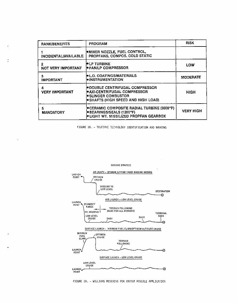
RANK/BENEFITS PROGRAM RISK
1 eMIXERNOZZLE,FUELCONTROL,INCIDENTAL/AVAILABLE PROPFANS,COMPOS.COLDSTATIC
2 eLp TURBINE LOWNOTVERYIMPORTANT eFAN/LPCOMPRESSOR
3 o LO. COATINGSIMATERIALS MODERATEIMPORTANT elNSTRUMENTATION
4 • DOUBLECENTRIFUGALCOMPRESSORVERYIMPORTANT IAXI-CENTRIFUGALCOMPRESSOR HIGH
• SLINGERCOMBUSTOR• SHAFTS(HIGH SPEEDANDHIGH LOAD)
5 oCERAMICCOMPOSITERADIALTURBINE(3000°F")MANDATORY • BEARINGSISEALS(1200°F") VERYHIGH
• LIGHTWI".MISSILIZEDPROPFANGEARBOX
FIGURE 18. - TELEDYNETECHNOLOGYIDENTIFICATION AND RANKING
SUBSONICSTRATEGIC
ATRLAUNClt- OPTIMUMALTITUDECRUISEIBASELINEMISSION1LAUNCHPOINT _ OPTIMUM
L._._ CRUISE
"_ DESCENDTO
ATION
AIR LAUNCII- LOWLEVELCRUISELAUNCH
POINT _STANDOFFRANGEI\ _l,-,.._.- TERRAINFOLLOWING_tALL MISSIONSI [ (SAMEFORALL MISSIONS)/" ' TERMINAL/ LOWLEVEL DASH
I'CRUISE DASH DA_' I_,_/ / \ I
SURFACELAUNCH- MINIMUM FUELCLIMB/0PTIMUMALTITUDECRUISE
MINIMUM
FUELS M.... TERRAIN
.F0LL0WING
SURFACELAUNCH- LOWLEVELCRUISE
LOWLEVELCRUISE
LAUNCHer IPOINT
FIGURE 19. - WILLIAMS MlSSlONS FOR CRUISEMISSILE APPLICATION

FIGURE20. - WILLIAMS REFERENCECRUISEMISSILE CONFIGURATION
RECUPERATED TURBOFAN
ADVANCED TURBOFAN
FIGURE 21. - WILLIAMS CRUISEMISSILE ENGINECONFIGURATIONS

REFERENCEMISSILEWITH
ADVANCEDENGINECOMPAREDTO REFERENCEENGINE
GROSSWEIGHT:ADVANCEDTURBOFAN -28.5%ADVANCEDRECUPERATED -27.6%
FUELBURNED:
ADVANCEDTURBOFAN -38.3%
ADVANCEDRECUPERATED -47.2%
LIFECYCLECOST:ADVANCEDTURBOFAN -56.0%ADVANCEDRECUPERATED -47.0%
FIGURE 22. - WILLIAMS MISSION ANALYSIS RESULTS FOR ADVANCED TECHNOLOGY RANKINGS
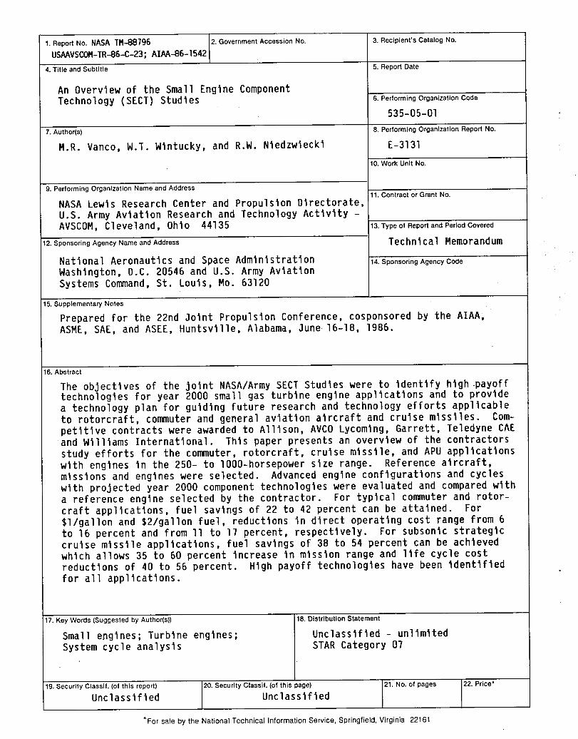
1. Report No. NASATM-88796 2. Government Accession No. 3. Recipient's Catalog No.
USAAVSCOM-TR-86-C-23;AIAA-86-1542
4.Titleand Subtitle 5.ReportDate
An Overviewof the Small EngineComponentTechnology (SECT) Studies B. Performing Organization Code
535-05-01
7.Author(s) 8.PerformingOrganizationReportNo.
M.R. Vanco, W.T. Wlntucky,and R.W. Nledzwleckl E-3131
10. Work Unit No.
9. Performing Organization Name and Address11. Contract or Grant No.
NASALewis Research Center and Propulsion Directorate,U.S. Army Aviation Research and Technology Activity -AVSCOM,Cleveland, 0hlo 44135 13. mype of Report and Period Covered
12. Sponsoring Agency Name and Address TechnI ca1 Memorand um
Natl onal Aeronautics and Space Admlnl stratton i14. Sponsoring Agency Code
Washington, D.C. 20546 and U.S. Army AviationSystems Command,St. Louis, Mo. 63120
15. Supplementary Notes
Prepared for the 22nd Joint Propulsion Conference, cosponsored by the AIAA,ASME, SAE, and ASEE, Huntsville, Alabama, 3une 16-18, 1986.
16. Abstract
The objectivesof the joint NASA/ArmySEC_ Studieswere to identifyhlgh.payofftechnologiesfor year 2000 small gas turbineengine applicationsand to providea technologyplan for guidingfuture researchand technologyeffortsapplicableto rotorcraft,commuterand generalaviationaircraftand cruise missiles. Com-petitivecontractswere awardedto Allison,AVCO Lycomlng,Garrett,TeledyneCAEand Williams International. Thls paper presentsan overviewof the contractorsstudy effortsfor the commuter,rotorcraft,cruise missile,and APU applicationswlth enginesIn the 250- to 1000-horsepowerslze range. Referenceaircraft,missions and engineswere selected. Advancedengine configurationsand cycleswlth projectedyear 2000 componenttechnologieswere evaluatedand comparedwltha referenceengine selectedby the contractor. For typicalcommuterand rotor-craft applications,fuel savingsof 22 to 42 percentcan be attained. For$1/gallonand $2/gallonfuel, reductionsin direct operatingcost range from 6to 16 percentand from II to 17 percent, respectively. For subsonic strategiccruise missile applications,fuel savingsof 38 to 54 percentcan be achievedwhich allows 35 to 60 percentincreaseIn mission range and llfe cycle costreductionsof 40 to 56 percent. Hlgh payoff technologieshave been identifiedfor all applications.
17. Key Words (Suggested by Author(s)) 18. Distribution Statement
Small engines; Turbine engines; Unclassified - unlimitedSystem cycle analysis STAR Category07
19. Security Classif. (of this report) 20. Security Classif. (of this page) 21. No. of pages 22, Price*
Unclassified Unclassified
*For sale by the National Technical Information Service, Springfield, Virginia 22161

?,_

Nationa,Aeronau,,csanS.CO OC.ASSMA,.I!1111Space Adminislration
Lewis ResearchCenter ADDRESSCORRECTIONREQUESTED
Cleveland.Ohio 44135
Official BusinessPenalty for Private Use $300 Postageand Fees Paid
National AeronauticsandSpace Administration '_,NASA-451
NASA