an1200.22 lora™ modulation basics - frugal prototype
TRANSCRIPT
Revision 2, May 2015 www.semtech.com P a g e | 1
©2015 Semtech Corporation
APPLICATION NOTE
AN1200.22
LoRa™ Modulation Basics
AN1200.22
LoRa™ModulationBasics
Revision 2, May 2015 www.semtech.com P a g e | 2
©2015 Semtech Corporation
APPLICATION NOTE
AN1200.22
LoRa™ Modulation Basics
Table of Contents 1 Introduction .......................................................................................................................................... 4
2 Acronyms .............................................................................................................................................. 5
3 Spread Spectrum Communications ...................................................................................................... 6
3.1 Shannon – Hartley Theorem ......................................................................................................... 6
3.2 Spread-Spectrum Principles .......................................................................................................... 7
3.3 Chirp Spread Spectrum ................................................................................................................. 9
4 LoRa Spread Spectrum .......................................................................................................................... 9
4.1 Key Properties of LoRa Modulation ............................................................................................ 11
4.1.1 Bandwidth Scalable ............................................................................................................. 11
4.1.2 Constant Envelope / Low-Power ......................................................................................... 11
4.1.3 High Robustness .................................................................................................................. 11
4.1.4 Multipath / fading Resistant ............................................................................................... 11
4.1.5 Doppler Resistant ................................................................................................................ 11
4.1.6 Long Range Capability ......................................................................................................... 11
4.1.7 Enhanced Network Capacity ............................................................................................... 11
4.1.8 Ranging / Localization ......................................................................................................... 12
4.2 FSK vs. LoRa Sensitivity Comparison ........................................................................................... 12
5 Considerations for Wireless Communications .................................................................................... 14
5.1 Wireless Network ........................................................................................................................ 14
5.1.1 Star Network Topology ....................................................................................................... 14
5.1.2 Mesh Network Topology ..................................................................................................... 14
5.2 Multipath Propagation Mechanisms .......................................................................................... 14
5.3 Link Budget.................................................................................................................................. 15
5.4 Interference Limited Links .......................................................................................................... 16
5.5 Network Coexistence .................................................................................................................. 17
5.6 Network Trial .............................................................................................................................. 21
6 Network Planning Example ................................................................................................................. 22
6.1 Capacity ....................................................................................................................................... 22
6.2 Link Budget.................................................................................................................................. 22
Revision 2, May 2015 www.semtech.com P a g e | 3
©2015 Semtech Corporation
APPLICATION NOTE
AN1200.22
LoRa™ Modulation Basics
6.3 Throughput Optimization ........................................................................................................... 23
6.3.1 Multi-PHY Mode Networks ................................................................................................. 23
7 Conclusions ......................................................................................................................................... 24
8 References: ......................................................................................................................................... 25
Index of Figures
Figure 1: Modulation / Spreading Process .................................................................................................... 7
Figure 2: Demodulation / De-spreading Process .......................................................................................... 8
Figure 3: Comparison of LoRa and FSK Sensitivity ...................................................................................... 12
Figure 4: Traditional Narrowband Signal vs. Wideband Interferer ............................................................. 17
Figure 5: Narrowband Signal vs. Wideband Interferer ............................................................................... 18
Figure 6: Wideband Signal vs. Narrowband Interferer ............................................................................... 19
Figure 7: Example of Burst Interference ..................................................................................................... 19
Figure 8: LoRa vs FSK Selectivity in the vicinity of an AM interfering Signal .............................................. 20
Figure 9: Shinjuku Urban Range Test .......................................................................................................... 21
Index of Tables
Table 1: Link Budget Comparison for Narrowband FSK .............................................................................. 22
Revision 2, May 2015 www.semtech.com P a g e | 4
©2015 Semtech Corporation
APPLICATION NOTE
AN1200.22
LoRa™ Modulation Basics
1 Introduction LoRa is a proprietary spread spectrum modulation scheme that is derivative of Chirp Spread Spectrum
modulation (CSS) and which trades data rate for sensitivity within a fixed channel bandwidth. It
implements a variable data rate, utilizing orthogonal spreading factors, which allows the system
designer to trade data rate for range or power, so as to optimize network performance in a constant
bandwidth.
LoRa is a PHY layer implementation and is agnostic with to higher-layer implementations. This allows
LoRa to coexist and interoperate with existing network architectures.
This application note explains some of the basic concepts of LoRa modulation and the advantages that
this modulation scheme can provide when deploying both fixed and mobile low-power real-world
communications networks.
Revision 2, May 2015 www.semtech.com P a g e | 5
©2015 Semtech Corporation
APPLICATION NOTE
AN1200.22
LoRa™ Modulation Basics
2 Acronyms
BT Bandwidth Time Product
CEPT ECC Conférence Européenne des administrations des Postes et des Télécommunications -
Electronics Communications Committee
CSMA Carrier Sense Multiple Access
CSMA-CA Carrier Sense Multiple Access with Collision Avoidance
CSS Chirp Spread Spectrum
dB Decibel
Eb/NO Energy per bit to noise-power spectral density ratio (normalized Signal-to-Noise Ratio)
ETSI European Telecommunications Standards Institute
DSSS Direct Sequence Spread Spectrum
FSK Frequency Shift Keying
IEEE Institute of Electrical and Electronic Engineers, Inc
LBT Listen Before Transmit
LoRa™ Semtech’s Long-Range modulation
LTE Long-term Evolution
M-LMS Multilateration Location and Monitoring Service
NPSTC National Public Safety Telecommunications Council
OFCOM Independent Regulator and Competition Authority for the UK Communications
Industries
O-QPSK Offset Quadrature Phase-Shift Keying
PHY Physical Layer
SNR Signal-to-Noise Ratio
Revision 2, May 2015 www.semtech.com P a g e | 6
©2015 Semtech Corporation
APPLICATION NOTE
AN1200.22
LoRa™ Modulation Basics
3 Spread Spectrum Communications
3.1 Shannon – Hartley Theorem
No discussion on spread spectrum techniques would be complete without a brief recap of the Shannon
– Hartley Theorem.
In information theory, the Shannon–Hartley theorem states the maximum rate at which information can
be transmitted over a communications channel of a specified bandwidth in the presence of noise.
The theorem establishes Shannon's channel capacity for a communication link and defines the
maximum data rate (information) that can be transmitted within a specified bandwidth in the presence
of noise interference:
� � � ∗ ���� � � � Equation 1
Where:
C = channel capacity (bit/s)
B = channel bandwidth (Hz)
S = average received signal power (Watts)
N = average noise or interference power (Watts)
S/N = signal to noise ratio (SNR) expressed as a linear power ratio
By rearranging Equation 1 from log base 2 to the natural log, e, and by noting that ln � ���� we can
manipulate the equation as follows:
�� � . ��� ∗ �
Equation 2
For spread spectrum applications the signal to noise ratio is small, since the signal power is often below
the noise floor. Assuming a noise level such that S/N << 1, Equation 2 can be re-written as:
�� �
��
Or:
� �
�� Equation 3
From equation 3 it can be seen that to transmit error free information in a channel of fixed noise-to-
signal ratio, only the transmitted signal bandwidth need be increased.
Revision 2, May 2015 www.semtech.com P a g e | 7
©2015 Semtech Corporation
APPLICATION NOTE
AN1200.22
LoRa™ Modulation Basics
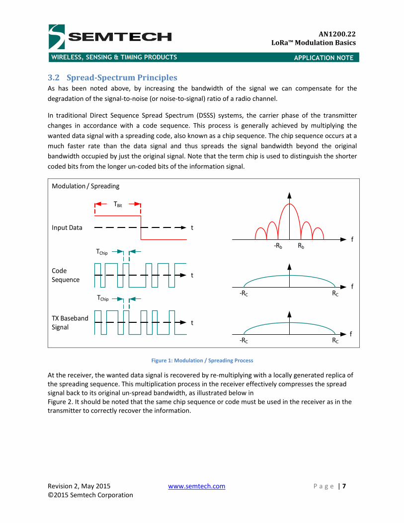
3.2 Spread-Spectrum Principles
As has been noted above, by increasing the bandwidth of the signal we can compensate for the
degradation of the signal-to-noise (or noise-to-signal) ratio of a radio channel.
In traditional Direct Sequence Spread Spectrum (DSSS) systems, the carrier phase of the transmitter
changes in accordance with a code sequence. This process is generally achieved by multiplying the
wanted data signal with a spreading code, also known as a chip sequence. The chip sequence occurs at a
much faster rate than the data signal and thus spreads the signal bandwidth beyond the original
bandwidth occupied by just the original signal. Note that the term chip is used to distinguish the shorter
coded bits from the longer un-coded bits of the information signal.
Modulation / Spreading
t
t
t
f
f
f
TBit
Input Data
Code
Sequence
TChip
TX Baseband
Signal
Rb-Rb
RC-RC
-RC RC
TChip
Figure 1: Modulation / Spreading Process
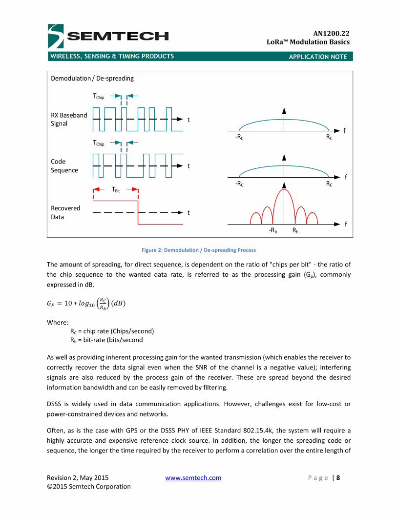
At the receiver, the wanted data signal is recovered by re-multiplying with a locally generated replica of
the spreading sequence. This multiplication process in the receiver effectively compresses the spread
signal back to its original un-spread bandwidth, as illustrated below in
Figure 2. It should be noted that the same chip sequence or code must be used in the receiver as in the
transmitter to correctly recover the information.
Revision 2, May 2015 www.semtech.com P a g e | 8
©2015 Semtech Corporation
APPLICATION NOTE
AN1200.22
LoRa™ Modulation Basics
Demodulation / De-spreading
t
t
t
f
f
TBit
Recovered
Data
Code
Sequence
TChip
RX Baseband
Signal
RC-RC
-RC RC
fRb-Rb
TChip
Figure 2: Demodulation / De-spreading Process
The amount of spreading, for direct sequence, is dependent on the ratio of "chips per bit" - the ratio of
the chip sequence to the wanted data rate, is referred to as the processing gain (Gp), commonly
expressed in dB.
�� � 10 ∗ ���"# $%$&� '()*
Where:
RC = chip rate (Chips/second)
Rb = bit-rate (bits/second
As well as providing inherent processing gain for the wanted transmission (which enables the receiver to
correctly recover the data signal even when the SNR of the channel is a negative value); interfering
signals are also reduced by the process gain of the receiver. These are spread beyond the desired
information bandwidth and can be easily removed by filtering.
DSSS is widely used in data communication applications. However, challenges exist for low-cost or
power-constrained devices and networks.
Often, as is the case with GPS or the DSSS PHY of IEEE Standard 802.15.4k, the system will require a
highly accurate and expensive reference clock source. In addition, the longer the spreading code or
sequence, the longer the time required by the receiver to perform a correlation over the entire length of
Revision 2, May 2015 www.semtech.com P a g e | 9
©2015 Semtech Corporation
APPLICATION NOTE
AN1200.22
LoRa™ Modulation Basics
the code sequence, or by either searching sequentially through code sequences or implementing
multiple correlators in parallel
This is especially of concern for power-constrained devices that cannot be “always-on” and thus need to
repeatedly and rapidly synchronize.
3.3 Chirp Spread Spectrum
Chirp Spread Spectrum was developed for radar applications in the 1940’s. Traditionally used in a
number of military and secure communications applications; over the past twenty years this modulation
technique has seen increased adoption in a number of data communications applications due to its
relatively low transmission power requirements and inherent robustness from channel degradation
mechanisms such as multipath, fading, Doppler and in-band jamming interferers.
A CSS PHY was adopted by the IEEE for the Low-Rate Wireless Personal Area Networks (LR-WPANs)
standard 802.15.4 for applications requiring longer range and mobility than that achievable with the O-
QPSK DSSS PHY mode.
4 LoRa Spread Spectrum Semtech’s LoRa modulation addresses all of the issues associated with DSSS systems to provide a low-
cost, low-power, yet above all robust alternative to the traditional spread-spectrum communications
techniques [1], [2].
In LoRa modulation the spreading of the spectrum is achieved by generating a chirp signal that
continuously varies in frequency. An advantage of this method is that timing and frequency offsets
between transmitter and receiver are equivalent, greatly reducing the complexity of the receiver design.
The frequency bandwidth of this chirp is equivalent to the spectral bandwidth of the signal.
The wanted data signal is chipped at a higher data rate and modulated onto the chirp signal.
The relationship between the wanted data bit rate, symbol rate and chip rate for LoRa modulation can
be expressed as follows:
We can define the modulation bit rate, Rb, as:
+, � -. ∗ "/012345
6789/9;<
Where:
SF = spreading factor (7..12)
BW = modulation bandwidth (Hz)
Revision 2, May 2015 www.semtech.com P a g e | 10
©2015 Semtech Corporation
APPLICATION NOTE
AN1200.22
LoRa™ Modulation Basics
Now define the symbol period, TS, as:
=� � >12�? 9;<9
Thus, symbol rate, RS, is the reciprocal of TS:
+� � "@1 �
�?>12 9AB6��9/9;<
Finally we can define the chip rate, RC, as:
+� � +� ∗ 2�D <E7F9/9;< As can be seen this provides the datasheet definition: “…one chip is sent per second per Hz of
bandwidth…” as can be seen below:
+� � +� ∗ 2�D
+� � �?>12 ∗ 2�D<E7F9/9;<
LoRa modulation also includes a variable error correction scheme that improves the robustness of the
transmitted signal at the expense of redundancy.
Thus we can define the nominal bit rate of the data signal as:
+, � -. ∗ G HHI%JK/012345
Where:
SF = spreading factor (7..12)
CR = code rate (1..4)
BW = modulation bandwidth (Hz)
If we define rate code, such that:
+L8;M�(; � NNO�$
We can rewrite nominal the bit rate as:
+, � -. ∗ $PQ��RS�/012345
6789/9;<

Revision 2, May 2015 www.semtech.com P a g e | 11
©2015 Semtech Corporation
APPLICATION NOTE
AN1200.22
LoRa™ Modulation Basics
4.1 Key Properties of LoRa Modulation
4.1.1 Bandwidth Scalable
LoRa modulation is both bandwidth and frequency scalable. It can be used for both narrowband
frequency hopping and wideband direct sequence applications. Unlike existing narrowband or wideband
modulation schemes, LoRa can be easily adapted for either mode of operation with only a few simple
configuration register changes.
4.1.2 Constant Envelope / Low-Power
Similar to FSK, LoRa is a constant envelope modulation scheme which means that the same low-cost and
low-power high-efficiency PA stages can be re-used without modification. In addition, due to the
processing gain associated with LoRa, the output power of the transmitter can be reduced compared to
a conventional FSK link while maintaining the same or better link budget.
4.1.3 High Robustness
Due to the high BT product (BT > 1) and their asynchronous nature a LoRa signal is very resistant to both
in-band and out-of-band interference mechanisms. Since the LoRa symbol period can be longer than the
typical short-duration burst of fast-hopping FHSS systems, it provides for excellent immunity to pulsed
AM interference mechanisms; typical receiver out-of-channel selectivity figures of 90 dB and co-channel
rejection of better than 20 dB can be obtained. This compares to typically 50 dB for adjacent and
alternate channel rejection, and -6 dB co-channel rejection for FSK modulation.
4.1.4 Multipath / fading Resistant
The chirp pulse is relatively broadband and thus LoRa offers immunity to multipath and fading, making it
ideal for use in urban and suburban environments, where both mechanisms dominate.
4.1.5 Doppler Resistant
Doppler shift causes a small frequency shift in the LoRa pulse which introduces a relatively negligible
shift in the time axis of the baseband signal. This frequency offset tolerance mitigates the requirement
for tight tolerance reference clock sources. LoRa is ideal for mobile data communications links such as
wireless tire-pressure monitoring systems, drive-by applications such as toll booth and mobile tag
readers, and trackside communications for railroad infrastructure.
4.1.6 Long Range Capability
For a fixed output power and throughput, the link budget of LoRa exceeds that of conventional FSK.
When taken into conjunction with the proven robustness to interference and fading mechanisms, this
improvement in link budget can readily translate to x4 and beyond enhancement in range.
4.1.7 Enhanced Network Capacity
Semtech LoRa modulation employs orthogonal spreading factors which enables multiple spread signals
to be transmitted at the same time and on the same channel without minimal degradation the RX
Revision 2, May 2015 www.semtech.com P a g e | 12
©2015 Semtech Corporation
APPLICATION NOTE
AN1200.22
LoRa™ Modulation Basics
sensitivity. Modulated signals at different spreading factors appear as noise to the target receiver and
can be treated as such.
4.1.8 Ranging / Localization
An inherent property of LoRa is the ability to linearly discriminate between frequency and time errors.
LoRa is the ideal modulation for radar applications and is thus ideally suited for ranging and localization
applications such as real-time location services.
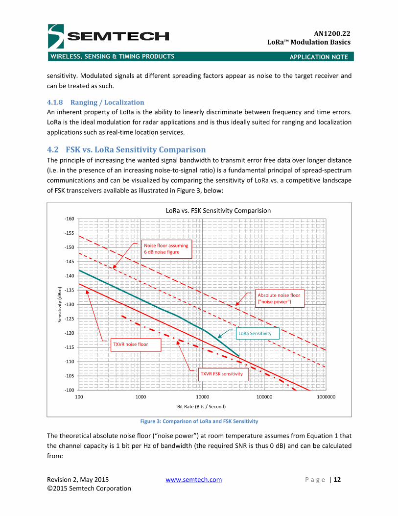
4.2 FSK vs. LoRa Sensitivity Comparison
The principle of increasing the wanted signal bandwidth to transmit error free data over longer distance
(i.e. in the presence of an increasing noise-to-signal ratio) is a fundamental principal of spread-spectrum
communications and can be visualized by comparing the sensitivity of LoRa vs. a competitive landscape
of FSK transceivers available as illustrated in Figure 3, below:
Figure 3: Comparison of LoRa and FSK Sensitivity
The theoretical absolute noise floor (“noise power”) at room temperature assumes from Equation 1 that
the channel capacity is 1 bit per Hz of bandwidth (the required SNR is thus 0 dB) and can be calculated
from:
-160
-155
-150
-145
-140
-135
-130
-125
-120
-115
-110
-105
-100
100 1000 10000 100000 1000000
Se
nsi
tivit
y (
dB
m)
Bit Rate (Bits / Second)
LoRa vs. FSK Sensitivity Comparision
Absolute noise floor
("noise power")
Noise floor assuming
6 dB noise figure
TXVR noise floor
LoRa Sensitivity
TXVR FSK sensitivity
Revision 2, May 2015 www.semtech.com P a g e | 13
©2015 Semtech Corporation
APPLICATION NOTE
AN1200.22
LoRa™ Modulation Basics
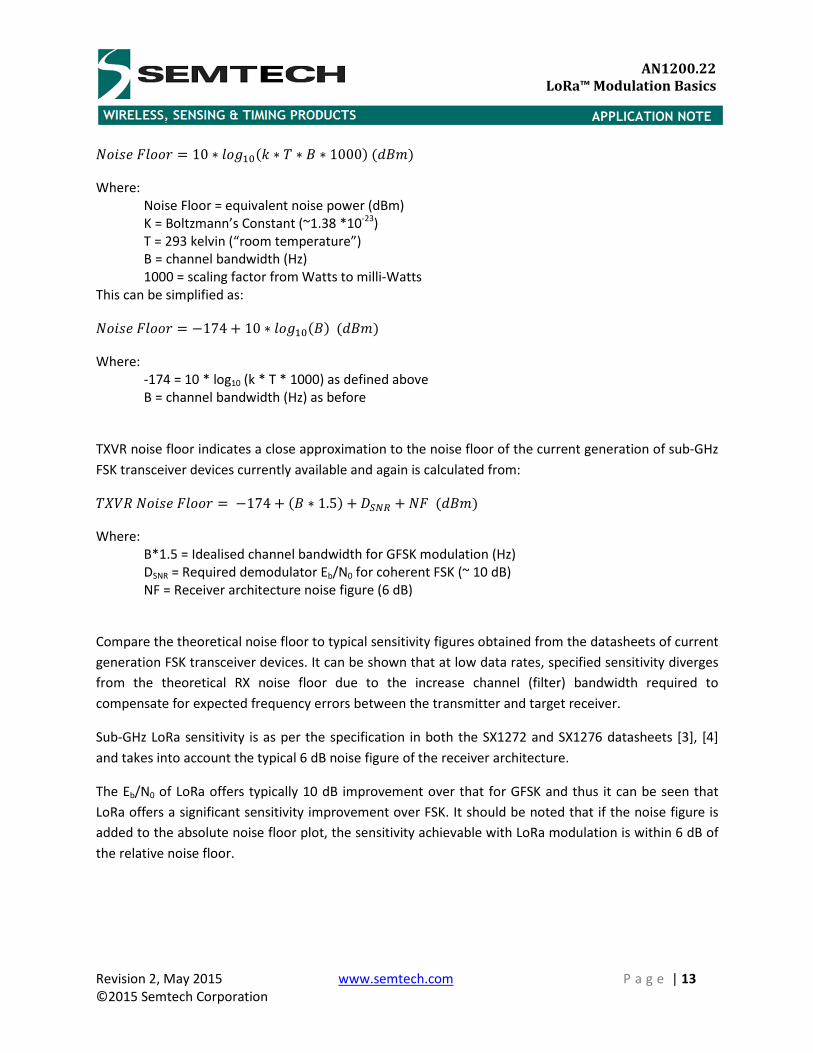
T�79;.���U � 10 ∗ ���"#'V ∗ = ∗ ) ∗ 1000*'()B* Where:
Noise Floor = equivalent noise power (dBm)
K = Boltzmann’s Constant (~1.38 *10-23
)
T = 293 kelvin (“room temperature”)
B = channel bandwidth (Hz)
1000 = scaling factor from Watts to milli-Watts
This can be simplified as:
T�79;.���U � W174 � 10 ∗ ���"#')*'()B* Where:
-174 = 10 * log10 (k * T * 1000) as defined above
B = channel bandwidth (Hz) as before
TXVR noise floor indicates a close approximation to the noise floor of the current generation of sub-GHz
FSK transceiver devices currently available and again is calculated from:
=Z[+T�79;.���U � W174 � ') ∗ 1.5* � ]��$ � T.'()B* Where:
B*1.5 = Idealised channel bandwidth for GFSK modulation (Hz)
DSNR = Required demodulator Eb/N0 for coherent FSK (~ 10 dB)
NF = Receiver architecture noise figure (6 dB)
Compare the theoretical noise floor to typical sensitivity figures obtained from the datasheets of current
generation FSK transceiver devices. It can be shown that at low data rates, specified sensitivity diverges
from the theoretical RX noise floor due to the increase channel (filter) bandwidth required to
compensate for expected frequency errors between the transmitter and target receiver.
Sub-GHz LoRa sensitivity is as per the specification in both the SX1272 and SX1276 datasheets [3], [4]
and takes into account the typical 6 dB noise figure of the receiver architecture.
The Eb/N0 of LoRa offers typically 10 dB improvement over that for GFSK and thus it can be seen that
LoRa offers a significant sensitivity improvement over FSK. It should be noted that if the noise figure is
added to the absolute noise floor plot, the sensitivity achievable with LoRa modulation is within 6 dB of
the relative noise floor.
Revision 2, May 2015 www.semtech.com P a g e | 14
©2015 Semtech Corporation
APPLICATION NOTE
AN1200.22
LoRa™ Modulation Basics
5 Considerations for Wireless Communications
5.1 Wireless Network
5.1.1 Star Network Topology
A star network is the most common form of network topology for power constrained end-point nodes
and is relatively simple to implement. Typically a central coordinator or concentrator acts as the conduit
for all network traffic. All network transmissions are routed via the central coordinator.
A star-network topology helps minimize the amount of network traffic. For a network that is not link-
constrained only 3 devices and two links are involved in any communications between two nodes. In
addition nodes are isolated from one another and provides for ease of replacing nodes. Centralization
allows for inspection of all network traffic at a single point.
A disadvantage of this topology is that failure of the coordinator will disable all network communications
5.1.2 Mesh Network Topology
In a mesh network data propagates through the network via every node. Mesh networks can be
considered flooding, whereby each node relays the same message regardless of the end destination or
routing, whereby the method propagates along a path to its destination. Networks typically employ
look-up tables or are self-routing.
Advantages of a mesh networks are the ability to “self-heal” and reconfigure themselves in the event of
a loss of connectivity to a node or group of nodes.
A disadvantage of this topology is the relatively increased complexity over traditional star networks and
an increase in network traffic due to the inherent in-built redundancy of the network. In addition the
increased traffic that each node has to handle means that mesh networks are typically implemented in
circumstances where the nodes are not power constrained.
5.2 Multipath Propagation Mechanisms
Multipath [5], [6], [7] is the propagation phenomenon that results in the transmitted radio signal
reaching the receiver by two or more paths. Multipath mechanisms include reflection from objects such
as building, mountains, large bodies of water, atmospheric ducting, ionospheric reflection and
refraction. It should be noted that these mechanisms can give rise to both constructive and destructive
interference. This later case causes fading to be observed
Multipath gives rise to small-scale fading effects:
• Rapid changes in signal strength over a small travelled distance or time interval
• Frequency drift and bandwidth spread effects caused by Doppler shifts on each multipath signal
Revision 2, May 2015 www.semtech.com P a g e | 15
©2015 Semtech Corporation
APPLICATION NOTE
AN1200.22
LoRa™ Modulation Basics
Multipath fading mechanisms can be considered as flat or frequency-selective fading.
In the case of flat fading, the bandwidth of the propagation channel is greater than that of the
transmitted signal. In this case, while the spectral properties of the signal are unaltered at reception, the
amplitude of the signal fluctuates with time due to changes in the gain of the channel caused by
multipath. Narrow-band FSK systems attempt to mitigate for the effects of flat-fading by implementing
spectral diversity techniques such as frequency hopping.
Frequency-selective fading is said to occur when the bandwidth of the propagation channel is less than
that of the transmitted signal. It can be seen that the flat-fading case is most common for narrowband
FSK modulation; although for high-data rate wideband and FSK modulation inter-symbol interference
can be introduced by multipath delay spreading causing distortion of the demodulated signal. To
overcome frequency-selective fading, high-data rate FSK systems may implement multi-level (or m-ary)
modulation to reduce the transmitted signal bandwidth. Multi-level FSK requires both more complicated
receiver architecture to successfully demodulate the transmitted signal and a higher SNR than two-level
FSK.
In addition to multipath fading, Doppler fading mechanisms may also need to be considered in the case
of mobile communication.
As has been noted, the relatively broadband nature and high BT of LoRa provides for excellent immunity
to multipath and fading mechanisms.
5.3 Link Budget
The link budget of a wireless system or network is a measure of all the gains and losses from the
transmitter, through the propagation channel, to the target receiver. These gains and losses include
system gains and losses associated with the antenna, matching networks, etc. as well as losses
associated propagation channel itself (either though modelling or measured data).
Typically randomly varying channel mechanisms such as multipath and Doppler fading are taken into
account by factoring additional margin depending on the anticipated severity.
The link budget of a network wireless link can be expressed as:
$̂_'()B* � @̂_'()B* � ��`�@ab'()* W c�`�@ab'()* W ��de��af'()* W g'()*
Revision 2, May 2015 www.semtech.com P a g e | 16
©2015 Semtech Corporation
APPLICATION NOTE
AN1200.22
LoRa™ Modulation Basics
Where:
PRX = the expected power incident at the receiver
PTX = the transmitted power
GSYSTEM = system gains such as those associated with directional antennas, etc.
LSYSTEM = losses associated with the system such as feed-lines, antennas (in the case of electrical
short antennas associated with many remote devices), etc.
LCHANNEL = losses due to the propagation channel, either calculated via a wide range of channel
models or from empirical data
M = fading margin, again either calculated or from empirical data
A communications channel is said to be link limited when the losses associated with the channel cause
the incident power level at the receiver to be below that required to meet the SNR requirement of the
receiver for correct demodulation of the received data.
5.4 Interference Limited Links
In practice, operating in license-exempt spectrum provides for no quality of service guarantee (as
opposed to licensed operation, whereby the network operator has paid a fee for exclusive access to the
spectrum being used) and a device operating in license-exempt spectrum is likely to be interference
rather than link-budget limited.
A typical scenario may see several co-located networks attempting to access the same frequency space
at the same time. While there are a number of collision mitigation mechanisms that can be
implemented, either through regulation (such as LBT or transmitter duty-cycle limits) or through
voluntary mechanisms such as CSMA / CSMA-CA, by the nature of dynamic interference mechanisms a
channel assessment at the transmitter may not necessarily coincide with the channel conditions at the
target device and the transmission may be blocked.
To avoid interference mechanisms, narrowband systems often implement frequency agility (or
frequency hopping) to avoid repeated operation on the same channel or frequency. As has been noted,
this frequency agility is also used by narrowband systems to mitigate for multipath propagation
properties.
However, the pseudo-random nature of the hop sequence employed (as is typically required by
regulation) can lead to a loss of a packet and subsequent channel synchronization due to either the
transmitter or target receiver jumping to an already occupied channel or having another transmitting
device hop to that frequency during a wanted transmission.
The requirement to frequency hop also leads to an increase in packet redundancy. While modern
narrowband receivers typically require only a short preamble sequence for synchronization there will be
a requirement to retransmit a message header so that the receiver can be assured that the received
broadcast is intended. In addition, most frequency hopping systems only remain on a channel for a few
milliseconds so as to minimize the probability of the channel becoming blocked by another unwanted
Revision 2, May 2015 www.semtech.com P a g e | 17
©2015 Semtech Corporation
APPLICATION NOTE
AN1200.22
LoRa™ Modulation Basics
transmission, thus in the case of a low data rate narrowband transmission the message overhead
increases still further.
Any loss of synchronization between transmitter and receiver will require the devices to undergo a
period of re-discovery and synchronization.
5.5 Network Coexistence
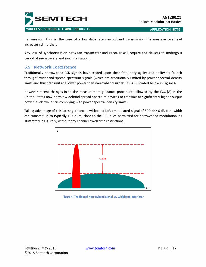
Traditionally narrowband FSK signals have traded upon their frequency agility and ability to “punch
through” wideband spread-spectrum signals (which are traditionally limited by power spectral density
limits and thus transmit at a lower power than narrowband signals) as is illustrated below in Figure 4.
However recent changes in to the measurement guidance procedures allowed by the FCC [8] in the
United States now permit wideband spread-spectrum devices to transmit at significantly higher output
power levels while still complying with power spectral density limits.
Taking advantage of this latest guidance a wideband LoRa modulated signal of 500 kHz 6 dB bandwidth
can transmit up to typically +27 dBm, close to the +30 dBm permitted for narrowband modulation, as
illustrated in Figure 5, without any channel dwell time restrictions.
~20 dB
Figure 4: Traditional Narrowband Signal vs. Wideband Interferer
Revision 2, May 2015 www.semtech.com P a g e | 18
©2015 Semtech Corporation
APPLICATION NOTE
AN1200.22
LoRa™ Modulation Basics
~ 3 dB
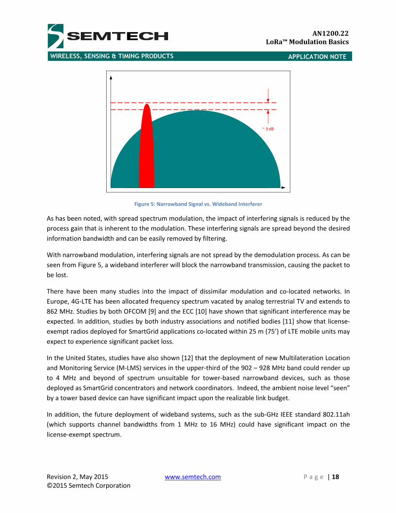
Figure 5: Narrowband Signal vs. Wideband Interferer
As has been noted, with spread spectrum modulation, the impact of interfering signals is reduced by the
process gain that is inherent to the modulation. These interfering signals are spread beyond the desired
information bandwidth and can be easily removed by filtering.
With narrowband modulation, interfering signals are not spread by the demodulation process. As can be
seen from Figure 5, a wideband interferer will block the narrowband transmission, causing the packet to
be lost.
There have been many studies into the impact of dissimilar modulation and co-located networks. In
Europe, 4G-LTE has been allocated frequency spectrum vacated by analog terrestrial TV and extends to
862 MHz. Studies by both OFCOM [9] and the ECC [10] have shown that significant interference may be
expected. In addition, studies by both industry associations and notified bodies [11] show that license-
exempt radios deployed for SmartGrid applications co-located within 25 m (75’) of LTE mobile units may
expect to experience significant packet loss.
In the United States, studies have also shown [12] that the deployment of new Multilateration Location
and Monitoring Service (M-LMS) services in the upper-third of the 902 – 928 MHz band could render up
to 4 MHz and beyond of spectrum unsuitable for tower-based narrowband devices, such as those
deployed as SmartGrid concentrators and network coordinators. Indeed, the ambient noise level “seen”
by a tower based device can have significant impact upon the realizable link budget.
In addition, the future deployment of wideband systems, such as the sub-GHz IEEE standard 802.11ah
(which supports channel bandwidths from 1 MHz to 16 MHz) could have significant impact on the
license-exempt spectrum.
Revision 2, May 2015 www.semtech.com P a g e | 19
©2015 Semtech Corporation
APPLICATION NOTE
AN1200.22
LoRa™ Modulation Basics
Wideband modulation systems are also subject to the same interference conditions. However, a
wideband modulation signal that is co-located with a second wideband signal of different spreading
factor or sequence will appear as noise to the target receiver and be treated as such.
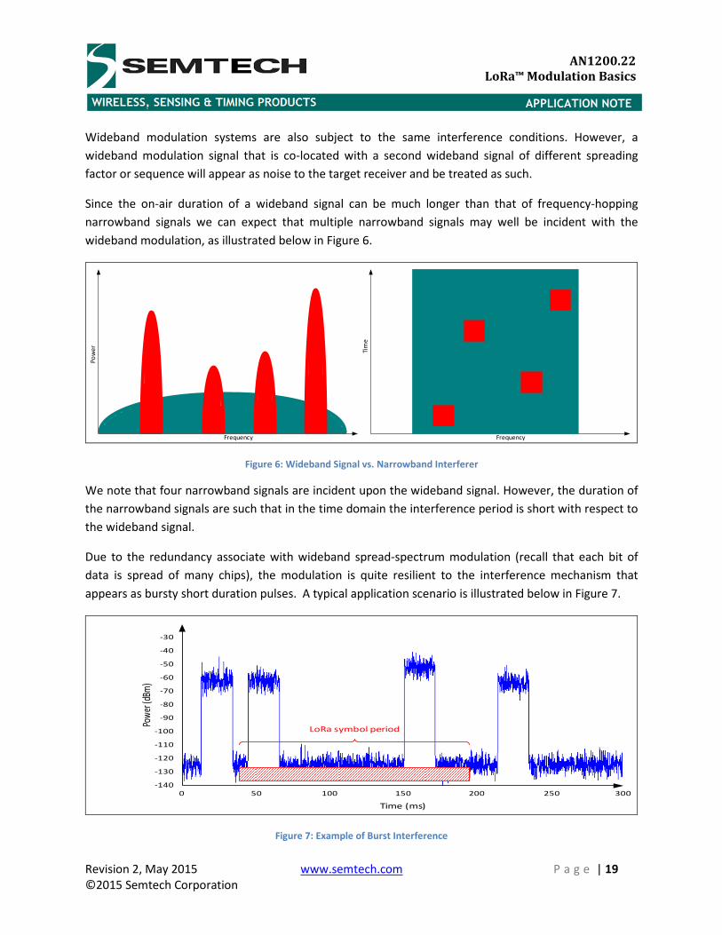
Since the on-air duration of a wideband signal can be much longer than that of frequency-hopping
narrowband signals we can expect that multiple narrowband signals may well be incident with the
wideband modulation, as illustrated below in Figure 6.
Frequency
Tim
e
Frequency
Po
we
r
Figure 6: Wideband Signal vs. Narrowband Interferer
We note that four narrowband signals are incident upon the wideband signal. However, the duration of
the narrowband signals are such that in the time domain the interference period is short with respect to
the wideband signal.
Due to the redundancy associate with wideband spread-spectrum modulation (recall that each bit of
data is spread of many chips), the modulation is quite resilient to the interference mechanism that
appears as bursty short duration pulses. A typical application scenario is illustrated below in Figure 7.
-30
-40
-50
-60
-70
-80
-90
-100
-110
-120
-130
-140
0 50 100 150 200 250 300
LoRa symbol period
Time (ms)
Pow
er (d
Bm)
Figure 7: Example of Burst Interference
Revision 2, May 2015 www.semtech.com P a g e | 20
©2015 Semtech Corporation
APPLICATION NOTE
AN1200.22
LoRa™ Modulation Basics
Semtech’s LoRa modulation, for example, can tolerate burst interference mechanisms of arbitrary
power levels for up to 30% of the symbol length with less than 6 dB sensitivity degradation.
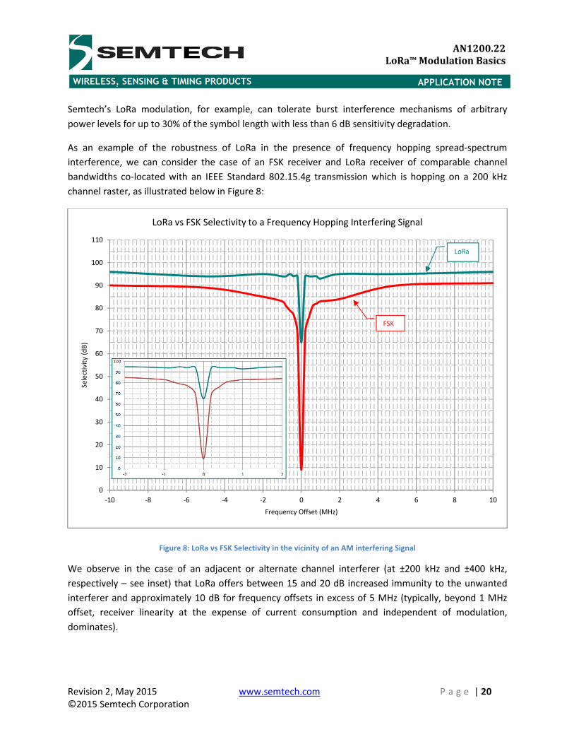
As an example of the robustness of LoRa in the presence of frequency hopping spread-spectrum
interference, we can consider the case of an FSK receiver and LoRa receiver of comparable channel
bandwidths co-located with an IEEE Standard 802.15.4g transmission which is hopping on a 200 kHz
channel raster, as illustrated below in Figure 8:
Figure 8: LoRa vs FSK Selectivity in the vicinity of an AM interfering Signal
We observe in the case of an adjacent or alternate channel interferer (at ±200 kHz and ±400 kHz,
respectively – see inset) that LoRa offers between 15 and 20 dB increased immunity to the unwanted
interferer and approximately 10 dB for frequency offsets in excess of 5 MHz (typically, beyond 1 MHz
offset, receiver linearity at the expense of current consumption and independent of modulation,
dominates).
0
10
20
30
40
50
60
70
80
90
100
110
-10 -8 -6 -4 -2 0 2 4 6 8 10
Se
lect
ivit
y (
dB
)
Frequency Offset (MHz)
LoRa vs FSK Selectivity to a Frequency Hopping Interfering Signal
FSK
LoRa
Revision 2, May 2015 www.semtech.com P a g e | 21
©2015 Semtech Corporation
APPLICATION NOTE
AN1200.22
LoRa™ Modulation Basics
5.6 Network Trial
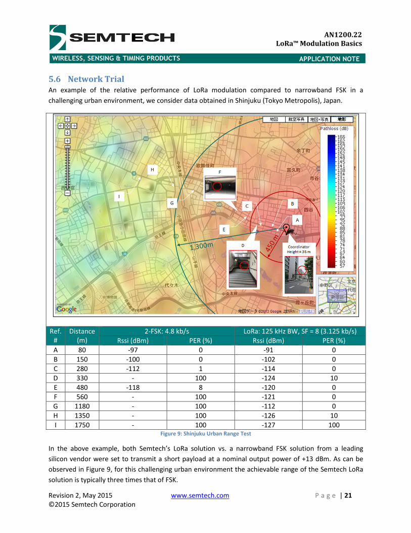
An example of the relative performance of LoRa modulation compared to narrowband FSK in a
challenging urban environment, we consider data obtained in Shinjuku (Tokyo Metropolis), Japan.
Ref.
#
Distance
(m)
2-FSK: 4.8 kb/s LoRa: 125 kHz BW, SF = 8 (3.125 kb/s)
Rssi (dBm) PER (%) Rssi (dBm) PER (%)
A 80 -97 0 -91 0
B 150 -100 0 -102 0
C 280 -112 1 -114 0
D 330 - 100 -124 10
E 480 -118 8 -120 0
F 560 - 100 -121 0
G 1180 - 100 -112 0
H 1350 - 100 -126 10
I 1750 - 100 -127 100
Figure 9: Shinjuku Urban Range Test
In the above example, both Semtech’s LoRa solution vs. a narrowband FSK solution from a leading
silicon vendor were set to transmit a short payload at a nominal output power of +13 dBm. As can be
observed in Figure 9, for this challenging urban environment the achievable range of the Semtech LoRa
solution is typically three times that of FSK.
Revision 2, May 2015 www.semtech.com P a g e | 22
©2015 Semtech Corporation
APPLICATION NOTE
AN1200.22
LoRa™ Modulation Basics
6 Network Planning Example
6.1 Capacity
One of the misconceptions concerning the use of spread spectrum wideband modulation is that it is
somehow spectral inefficient compared to narrowband modulation. However, consider the case of a
narrowband system operating in a virtual channel of 125 kHz bandwidth.
If we assume the case of 12 narrowband FSK channels transmitting at an equivalent bit rate of 1.2 kb/s,
then we can calculate the total theoretical channel capacity as:
MLFL<78AD�h � 12 ∗ 1.2V6/9 � 14.4V6/9
If we now consider the same available spectrum deployed as a single 125 kHz LoRa channel, and taking
advantage of the orthogonal spreading factors, the equivalent capacity of the channel is now:
MLFL<78AfR$P � 1 ∗ '-.12 � -.11 � -.10 � -.9 � -.8 � -.7 � -.6* � 1 ∗ '293 � 537 � 976 � 1757 � 3125 � 5468 � 9375*6/9 � 21.531V6/9
Thus it can be seen that deploying LoRa modulation provides for a total channel capacity of 21.5 kb/s.
This is an increase in channel capacity of nearly 50% compared to FSK.
6.2 Link Budget
If we now consider the link budget that can be obtained for each modulation scheme and using the
example above and assume a sensitivity of -122 dBm that is specified for a conventional FSK transceiver,
and compare against that obtainable using LoRa; for a fixed transmitter output power we observe the
following link budget delta as tabulated in Table 1, below.
Mode Equivalent bit rate (kb/s) Sensitivity (dBm) Δ (dB)
FSK 1.2 -122 -
LoRa SF = 12 0.293 -137 +15
LoRa SF = 11 0.537 -134.5 +12.5
LoRa SF = 10 0.976 -132 +10
LoRa SF = 9 1757 -129 +7
LoRa SF = 8 3125 -126 +4
LoRa SF = 7 5468 -123 +1
LoRa SF = 6 9375 -118 -3 Table 1: Link Budget Comparison for Narrowband FSK
Revision 2, May 2015 www.semtech.com P a g e | 23
©2015 Semtech Corporation
APPLICATION NOTE
AN1200.22
LoRa™ Modulation Basics
Thus we observe that even when transmitting at greater than 4 times the equivalent data rate, LoRa
modulation offers similar sensitivity to a conventional FSK system. When the data rate is approximately
equivalent the improvement with LoRa is between 7 and 10 dB.
If we consider our channel capacity scenario above, we can see with an equivalent link budget, LoRa can
actually transmit a data packet in a quarter of the time required for the FSK system.
Thus assuming a simple TDD or time division multiplexing of the radio channel, LoRa can communication
with x4 the number of devices as the FSK system.
6.3 Throughput Optimization
For a wireless network it can be expected that propagation loss increases with distance from the
network coordinator. For narrowband systems this may require additional nodes to be located in a mesh
network topology (with increased network complexity and redundancy) or the addition of repeaters for
a star network topology to ensure that every device in the network is covered. Unfortunately, the costs
associated with installing a repeater can run to between x100 and x1000 the cost of the hardware.
LoRa can minimize this cost by taking advantage of the property that signals with a different spreading
factor or sequence will appear as noise at the target receiver. Nodes that are closest to the network
coordinator, where path loss allows for transmission at a higher data rate can transmit at the maximum
data rate available; as path loss increases with distance the data throughput can be throttled back by
increasing the spreading factor or reducing spreading bandwidth
6.3.1 Multi-PHY Mode Networks
For still higher data rates it can be noted that Semtech’s SX127x family of low-power transceiver devices
provide for multiple PHY mode operation. Where channel conditions allow, higher data rate FSK
modulation can also be employed. As propagation loss increases, LoRa modulation of differing
bandwidth and spreading factors can be employed, each transmission tailored to the channel conditions
to ensure sufficient link margin. Unlike FSK, LoRa transmissions of differing modulation bandwidth and
spreading factors can co-exist.
For dynamic network conditions it is noted that Semtech’s radios can be easily and remotely configured
over-the-air.
Revision 2, May 2015 www.semtech.com P a g e | 24
©2015 Semtech Corporation
APPLICATION NOTE
AN1200.22
LoRa™ Modulation Basics
7 Conclusions Semtech’s LoRa modulation is a simple PHY layer implementation that provides significant link budget
improvement over conventional narrowband modulation. In addition the enhanced robustness and
selectivity provided by the spread spectrum modulation enables greater transmission distance to be
obtained, even in harsh, challenging environments.
LoRa modulation uses orthogonal spreading factors. This enables multiple packets of differing spreading
factors to be in the same channel concurrently, significantly improving network efficiency and
throughput.
Semtech’s family of multi-PHY mode transceivers allow for LoRa to coexist and interoperate with
existing legacy network deployments.
Revision 2, May 2015 www.semtech.com P a g e | 25
©2015 Semtech Corporation
APPLICATION NOTE
AN1200.22
LoRa™ Modulation Basics
8 References: [1]. Semtech Application Note AN1200.13, “SX1272/3/6/7/8: LoRa Modem Designer’s Guide”
(http://www.semtech.com/images/datasheet/LoraDesignGuide_STD.pdf)
[2]. Semtech Application Note AN1200.17, “SX1272/3/6/7/8: LoRa Energy Consumption Design”
(http://www.semtech.com/images/datasheet/LoraLowEnergyDesign_STD.pdf)
[3]. SX1272 Datasheet (http://www.semtech.com/apps/filedown/down.php?file=sx1272.pdf)
[4]. SX1276 Datasheet (http://www.semtech.com/apps/filedown/down.php?file=sx1276.pdf)
[5]. Rappaport, “Wireless Communications Principals and Practices,” (Prentice-Hall)
[6]. Xiong, “Digital Modulation Techniques, 2nd ed.,” (Artech House)
[7]. Siwak, Bahreini, “Radiowave Propagation and Antennas, ” (Artech House)
[8]. FCC Office of Engineering and Technology Laboratory Division “Guidance for Performing
Compliance Measurements on Digital Transmission Systems (DTS) Operating Under §15.247”
(https://apps.fcc.gov/oetcf/kdb/forms/FTSSearchResultPage.cfm?switch=P&id=21124)
[9]. OFCOM, “Use of Short Range Devices alongside mobile broadband services operating in the
800MHz band”
[10]. CEPT ECC Report 207, Adjacent band co-existence of SRDs in the band 863-870 MHz in light of
the LTE usage below 862 MHz
[11]. ERA Technology, “Investigation on the receiver characteristics of SRD equipment in the 863-
870 MHz band”
[12]. NPSTC, “Public Safety Related Spectrum Issues in the 902-928 MHz Band”
Revision 2, May 2015 www.semtech.com P a g e | 26
©2015 Semtech Corporation
APPLICATION NOTE
AN1200.22
LoRa™ Modulation Basics
© Semtech 2015
All rights reserved. Reproduction in whole or in part is prohibited without the prior written consent of the copyright owner. The
information presented in this document does not form part of any quotation or contract, is believed to be accurate and reliable
and may be changed without notice. No liability will be accepted by the publisher for any consequence of its use. Publication
thereof does not convey nor imply any license under patent or other industrial or intellectual property rights. Semtech assumes
no responsibility or liability whatsoever for any failure or unexpected operation resulting from misuse, neglect improper
installation, repair or improper handling or unusual physical or electrical stress including, but not limited to, exposure to
parameters beyond the specified maximum ratings or operation outside the specified range.
SEMTECH PRODUCTS ARE NOT DESIGNED, INTENDED, AUTHORIZED OR WARRANTED TO BE SUITABLE FOR USE IN LIFE-
SUPPORT APPLICATIONS, DEVICES OR SYSTEMS OR OTHER CRITICAL APPLICATIONS. INCLUSION OF SEMTECH PRODUCTS IN
SUCH APPLICATIONS IS UNDERSTOOD TO BE UNDERTAKEN SOLELY AT THE CUSTOMER’S OWN RISK. Should a customer
purchase or use Semtech products for any such unauthorized application, the customer shall indemnify and hold Semtech and
its officers, employees, subsidiaries, affiliates, and distributors harmless against all claims, costs damages and attorney fees
which could arise.
Contact Information
Semtech Corporation
Wireless Sensing and Timing Products Division
200 Flynn Road, Camarillo, CA 93012
Phone: (805) 498-2111 Fax: (805) 498-3804
E-mail: [email protected]
Internet: http://www.semtech.com