an657: thermal management and mechanical handling for
TRANSCRIPT

August 2014 Altera Corporation
AN-657-1.2
© 2014 Altera Corporation. AlQUARTUS and STRATIX worOffice and in other countries.respective holders as describedproducts to current specificatioproducts and services at any tiof any information, product, oadvised to obtain the latest verfor products or services.
101 Innovation DriveSan Jose, CA 95134www.altera.com
Thermal Management and MechanicalHandling for Altera TCFCBGA Devices
Application Note
This application note describes the thermal composite flip chip ball-grid array(TCFCBGA) package for the Arria V device family.
TCFCBGA improves board real-estate use by allowing closer spacing between passivecomponents and the flip chip die, providing better warpage control for thin coresubstrates, and improving solder joint reliability.
This application note includes the following sections:
■ “TCFCBGA Overview”
■ “Case Studies” on page 4
■ “Heat-Sink Attachment” on page 5
■ “Device Reworkability” on page 8
■ “Handling and Transfer” on page 10
■ “Selecting Heat Sink for Small Heat Source” on page 10
■ “General Properties of TIM II” on page 11
■ “Compression During Heat Sink Attachments” on page 13
■ “Vendors List” on page 14
TCFCBGA OverviewTCFCBGA packages are designed to allow die protrusion over the mold cap. Thisfeature ensures the thinnest band line and best thermal impedance between the flipchip die and the attached heat sink.
The TCFCBGA is produced in an exposed die configuration. This configurationmaintains the excellent thermal performance of a bare die flip chip BGA and isenhanced by providing a support surface around the bare die for a direct heat-sinkattachment.
l rights reserved. ALTERA, ARRIA, CYCLONE, HARDCOPY, MAX, MEGACORE, NIOS,ds and logos are trademarks of Altera Corporation and registered in the U.S. Patent and TrademarkAll other words and logos identified as trademarks or service marks are the property of their
at www.altera.com/common/legal.html. Altera warrants performance of its semiconductorns in accordance with Altera's standard warranty, but reserves the right to make changes to any
me without notice. Altera assumes no responsibility or liability arising out of the application or user service described herein except as expressly agreed to in writing by Altera. Altera customers aresion of device specifications before relying on any published information and before placing orders
Feedback Subscribe
ISO9001:2008Registered

Page 2 TCFCBGA Overview
Figure 1 and Figure 2 show the package construction and cross-section of theTCFCBGA.
Figure 1. Package Construction of a TCFCBGA
Figure 2. Cross-Sectional View of an TCFCBGA Package
Note to Figure 2:(1) Build-up layers stack on both sides of the bismaleimide triazine (BT) core.
Substrate
Die
Molding Compound
High Density Substrate
BT Core
Solder Ball Build-Up Layers (1)
Silicon DieSolder Bump Molding Compound
Thermal Management and Mechanical Handling for Altera TCFCBGA Devices August 2014 Altera Corporation

TCFCBGA Overview Page 3
Die to Package ProfileTo calculate the amount of thermal interface material type II (TIM II) for the heat-sinkattachment, you must consider the height of the die above the package body. Figure 3and Table 1 list the dimensions of the TCFCBGA package. For phase change materials(PCMs), thermal conductive tapes, and thermal gap fillers, make sure there is enoughTIM II to cover the edge of the die. This practice protects the die edge from chippingor cracking.
Figure 3. Die to Package Profile
TIM II must fill undercut, H, around the die, and conform over the die
DieMold cap edge Mold cap edge
PcenterPedge
HW
Table 1. Die to Package Dimensions
Parameter Average Maximum
Pedge 35 m 43 m
Pcenter 46 m 65 m
H 109 m 143 m
W 2.5 mm 2.9 mm
Thermal Management and Mechanical Handling for Altera TCFCBGA DevicesAugust 2014 Altera Corporation

Page 4 Case Studies
st Case 7
50 x 50
15
echanicaltachment,er body size
ush pins
ulder screw
15
PCM
1.1
81.4
85.0
3.6
200 ft/min.r sales
Case StudiesThe following sections describe the test cases for different combinations of heat-sinktypes and TIM IIs.
Simulated DataThis case study was set up to determine the heat sinks and TIM IIs for use with thethermal composite TCFCBGA. Altera simulated the thermal tests using theparameters in Table 2.
Simulation SummaryTest cases 1, 2, and 3 use epoxy as TIM II with a non-mechanical heat-sink attachment.
■ At 2 W to 5 W, the non-mechanical heat sink with epoxy is sufficient
■ As power approaches and exceeds 10 watts, consider a mechanical attachmentwith heat sinks that are larger than package body size
Test cases 4, 5, and 6 use PCM as TIM II with a mechanical heat-sink attachment.
■ At 2 W to 5 W, the mechanical attachment heat sinks with PCM is sufficient
■ As power approaches and exceeds 10 watts, consider mechanical attachment withheat sinks that are larger than package body size
Table 2. Heat Sink and TIM II Simulation (1), (2)
Parameter Test Case 1 Test Case 2 Test Case 3 Test Case 4 Test Case 5 Test Case 6 Te
Heat sink size (mm2) 40 x 40 40 x 40 40 x 40 40 x 40 40 x 40 40 x 40
Fin count 12 12 12 12 12 12
Heat sink typeNon-
mechanicalattachment
Non-mechanicalattachment
Non-mechanicalattachment
Mechanicalattachment,
same body size
Mechanicalattachment,
same body size
Mechanicalattachment,
same body size
Mat
larg
Fastener Regular Regular RegularZ-clips Z-clips Z-clips P
Talon clips Talon clips Talon clips Sho
Power (W) 2 5 10 2 5 10
TIM II Epoxy Epoxy Epoxy PCM PCM PCM
Interface loss (°C) 2.2 5.5 11 0.1 0.4 0.7
Actual case temp (°C) 63.6 76.5 98.0 61.5 71.3 87.7
Case/Junction temptarget (°C) 85.0 85.0 85.0 85.0 85.0 85.0
Difference (°C) 21.4 8.5 -13.0 23.5 13.7 -2.7
Notes to Table 2:(1) The case studies were conducted using a 40 mm x 40 mm TCFCBGA package with a representative die size of 13 mm x 14 mm, and an air flow of(2) This study was based on a specific die size and air flow. Different conditions will produce different results. Contact your local Altera sales office o
representative for specific application needs.
Thermal Management and Mechanical Handling for Altera TCFCBGA Devices August 2014 Altera Corporation

Heat-Sink Attachment Page 5
Test case 7 uses PCM as TIM II with a mechanical heat-sink attachment.
■ The mechanical heat-sink attachment has a body size larger than the TCFCBGApackage. This setup is sufficient to cool down the device for a high poweroperation.
Heat-Sink AttachmentThere are two types of attachments for heat sinks: mechanical and non-mechanical.Figure 4, Figure 5, and Figure 6 show the different heat-sink attachments.
Figure 4. Non-Mechanical Attachment Type
Figure 5. Mechanical Attachment Type with Minimum Extra Space
Epoxy
Regular heat sink with epoxy Regular heat sink with thermal tape
Z-clips Talon clips
Thermal Management and Mechanical Handling for Altera TCFCBGA DevicesAugust 2014 Altera Corporation

Page 6 Heat-Sink Attachment
Non-mechanical heat-sink attachments are preferred if there are space constraint onthe existing boards. There is no additional process of drilling holes on the PCB forlocking pins. The TIM II associated with these non-mechanical heat-sink attachmentsare epoxy or thermal conductive tape. These TIM IIs usually have low conductivity.
Mechanical heat-sink attachments need extra space around the device for push pins orshoulder screws, although Z-clips and talon clips require less extra PCB space. TheTIM II associated with these mechanical heat-sink attachments are PCM, thermalgrease, and thermal gap filler. The conductivity of these TIM IIs are usually higherthan epoxy and thermal conductive tape.
Although the case studies indicated that epoxy thermal performance is similar toPCM, heat sinks with non-mechanical attachments may damage the die. It is alsomore difficult to control the bond line thickness of epoxy with manual attachment,making it harder to control the thermal performance of the heat sinks.
Figure 7 and Figure 8 show the risk of die damage and poor thermal performance dueto uneven heat sink placement for non-mechanical heat-sink attachment.
Figure 6. Mechanical Attachment Type with Lock Down Pins
Push pins Shoulder screws
Figure 7. Die Damage
PCB
Die MoldingMolding
Heat sink
Substrate
Damage
Thermal Management and Mechanical Handling for Altera TCFCBGA Devices August 2014 Altera Corporation

Heat-Sink Attachment Page 7
With mechanical heat-sink attachments, there is even force on all sides of the heatsink, resulting in an even bond line thickness of the TIM II and even dissipation ofheat from the heat sink. Figure 9 shows the even compressive force on the heat-sinkmount with mechanical attachment.
Figure 8. Uneven Bond Line Thickness of TIM II
Figure 9. Mechanical Heat-Sink Attachment
PCB
Die MoldingMolding
Heat sink
Substrate
Uneven TIM II
Even force Even force
MoldingMoldingSubstrate
Die
Heat sinkTIM II
Push pins
PCB
Thermal Management and Mechanical Handling for Altera TCFCBGA DevicesAugust 2014 Altera Corporation

Page 8 Device Reworkability
lcahol
Device ReworkabilityTable 3 summarizes the reworkability of different combinations of heat sinks andTIM IIs.
Rework or Removal of Heat SinksTo remove a heat sink attached with thermal conductive tape, perform the followingsteps:
1. Carefully insert the edge of a razor blade between the device and the heat sink.Avoid inserting the entire blade. You only need to create a narrow separationspace.
2. Remove the blade and insert the spatula. Twist the spatula slowly to exert upwardpressure on the package while moving it inward as the heat sink begins toseparate. Avoid touching the die with the metal spatula.
3. To remove the remaining adhesive from the device surface, apply isopropylalcohol on the remaining adhesive. After few seconds, wipe the adhesive awaycarefully.
4. Check for damage to the die edge.
Figure 10 shows the removal of the heat sink attached with thermal conductive tape.
Table 3. Heat Sink and TIM II Reworkability
Heat Sink Type TIM II Type Application Reworkability
Non-mechanicalattachment
Epoxy Difficult to control the bond line thickness. Maynot have optimal thermal performance.
High risk of damagingthe device or PCB
Thermalconductivetape
Difficult to conform to the contours of theTCFCBGA package, as shown in Figure 3. Maynot have optimal thermal performance.
High risk of damagingthe device or PCB
Mechanical attachment
PCM Pre-cut to size. Conforms to contour of device Easy to remove
Gap filler Pre-cut to size. Conforms to contour of device.May not have optimal thermal performance Easy to remove
Thermal grease High performance, Conforms to contour ofdevice. Pump-out concerns. Easy to remove
Figure 10. thermal Conductive Tape Removal
Twist the spatula to separate the heat sink from the device Remove remainig adhesive with isoprolyl a
Insert blade
Thermal Management and Mechanical Handling for Altera TCFCBGA Devices August 2014 Altera Corporation
Device Reworkability Page 9
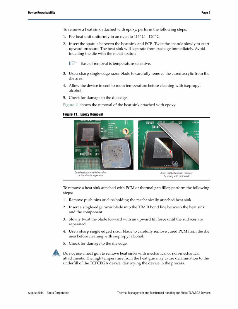
To remove a heat sink attached with epoxy, perform the following steps:
1. Pre-heat unit uniformly in an oven to 115° C – 120° C.
2. Insert the spatula between the heat sink and PCB. Twist the spatula slowly to exertupward pressure. The heat sink will separate from package immediately. Avoidtouching the die with the metal spatula.
1 Ease of removal is temperature sensitive.
3. Use a sharp single-edge razor blade to carefully remove the cured acrylic from thedie area.
4. Allow the device to cool to room temperature before cleaning with isopropylalcohol.
5. Check for damage to the die edge.
Figure 11 shows the removal of the heat sink attached with epoxy.
To remove a heat sink attached with PCM or thermal gap filler, perform the followingsteps:
1. Remove push pins or clips holding the mechanically attached heat sink.
2. Insert a single-edge razor blade into the TIM II bond line between the heat sinkand the component.
3. Slowly twist the blade forward with an upward tilt force until the surfaces areseparated.
4. Use a sharp single edged razor blade to carefully remove cured PCM from the diearea before cleaning with isopropyl alcohol.
5. Check for damage to the die edge.
c Do not use a heat gun to remove heat sinks with mechanical or non-mechanicalattachments. The high temperature from the heat gun may cause delamination to theunderfill of the TCFCBGA device, destroying the device in the process.
Figure 11. Epoxy Removal
Cured residual material remains on the die after separation
Cured residual material removed by wiping with razor blade
Thermal Management and Mechanical Handling for Altera TCFCBGA DevicesAugust 2014 Altera Corporation

Page 10 Handling and Transfer
Handling and TransferTCFCBGA devices must be handled with great care at all times. They should remainsecure in their TCFCBGA tray carriers except during transfer operations from tray totray. You must use the correct TCFCBGA trays specified for the size and pin count ofthe thermal composite TCFCBGA. Table 4 lists the TCFCBGA tray specifications forthe different TCFCBGA packages.
Do not use tweezers of any form to pick up the TCFCBGA device. Tweezers can causemechanical damage to the die, whether as scratches to the top of the die or to the bulksilicon in the form of chipped-outs, micro-cracks, or cracks. Altera recommends youmanually handle the devices using suitable design tools such as vacuum pencils withrubberized tips for pick-ups.
You must use a soft silicon or rubber tip for automated pick and place machines. Thepick and place pressure must be minimized to prevent damage to the die area of thedevice.
If you must replace the existing solder balls of the device, use the right fixture toprevent the die chipping on the device.
Selecting Heat Sink for Small Heat SourceIt is difficult to cool a smaller heat source because the heat sink's base material resiststhe spreading of the heat, through the base, to the outer fins. Figure 12 shows analuminum heat sink with a small heat source.
1 Current Altera devices that are small heat sources are the lidless FBGA and theTCFCBGA.
Table 4. TCFCBGA Tray Specifications
Package Size (Pin Count) Tray Part Number
27 mm x 27 mm (F672) Daewon 125-2727-919
29 mm x 29 mm (F780) Daewon 1F1-2929-C19
31 mm x 31 mm (F896) Kostat KS-880120
35 mm x 35 mm (F1152) Daewon 125-3535-919
40 mm x 40 mm (F1517) Kostat KS-886H
Figure 12. Small Heat Source with Aluminium Heat Sink
Small heat source
Aluminium heat sink
Die
Thermal Management and Mechanical Handling for Altera TCFCBGA Devices August 2014 Altera Corporation

General Properties of TIM II Page 11
To spread the heat from a small heat source to the entire base, some heat sink vendorsoffer efficient and reliable copper embedded heat sinks. Figure 13 shows a copperembedded heat sink. For a list of TIM II, heat sink, and TCFCBGA tray vendors, referto “Vendors List” on page 14.
General Properties of TIM IIAltera recommends you consider early in your design what type of suitable TIM II touse. TIM IIs can be the limiting factors in the expense of thermal managementdesigns. You can use TIM II effectively to help reduce the size of the heat sinks and theneed for larger cooling fans. The extended benefit of an effective TIM II is a solutionthat is faster, easier to apply, and less costly than changing heat sinks or redesigning achassis.
Several material solutions exist that can perform the functions of a TIM II—adhesives,grease, gels, PCMs, and pads. There are advantages and disadvantages associatedwith each of these TIM II solutions.
Thermal Adhesives or EpoxiesThermal adhesives are particle-laden, one- or two-component materials that areapplied via dispensing or stencil printing. Adhesives are cured to allow forcross-linking of the polymer, which provides the adhesive property. Thermaladhesives are advantageous because they provide structural support, eliminating theneed for mechanical clamping.
The disadvantages of using thermal adhesives or epoxies include the following:
■ They may not provide sufficient bond strength because of the small contact area
■ The relative high impedance will affect the thermal performance significantly
■ Device rework is very difficult and may result in damaging the device
Figure 13. Small Heat Source with Copper Embedded Heat Sink
Aluminium heat sink
Small heat sourceDie
Copper Heat Spreader
Thermal Management and Mechanical Handling for Altera TCFCBGA DevicesAugust 2014 Altera Corporation

Page 12 General Properties of TIM II
Thermal Conductive TapesThermally conductive adhesive tapes are convenient for heat-sink attachments withmid-range thermal performance. They eliminate the need for mechanical clamping.
The disadvantages of using thermal conductive tapes include the following:
■ Thermal conductive tape works best on flat surfaces. Plastic ICs are usuallyconcave in the center and heat-sink surfaces may vary. This unevenness can resultin air gaps in the interface.
■ May not be able to fill up all the gaps because of the contours of the TCFCBGA(See Figure 3 on page 3). This can result in air gaps in the interface.
■ Device rework is very difficult and may result in damaging the device.
■ Heat sinks may come off over time because of the heat and weight of the heat sinksfor PCBs that are mounted vertically.
Thermal GreaseThermal grease contains silicone oils that are loaded with thermally conductive filler.Thermal grease does not require curing and it flows and conforms to surfaces. It alsooffers a reworkable thermal interface layer. Thermal grease requires mechanicalclamping.
A disadvantage of using thermal grease is that it can degrade, pump-out, or dry outduring extended operation and over time, causing the thermal performance of theTIM II system using the grease to suffer significantly.
Thermal GelsThermal gels are low modulus, paste-like materials that are lightly cross-linked. Theyperform like grease with respect to their ability to conform to surfaces, while reducingmaterial pump-out. Thermal gels require mechanical clamping.
PCMsPCMs undergo a transition from a solid to a semi-solid phase with the application ofheat and pressure. The material is in a liquid phase at die-operating conditions. PCMsoffer several advantages, including the ability to conform to the mating surfaces andno curing is needed. PCMs require mechanical clamping.
Thermal PadsThermal pads are fabricated by molding non-reinforced silicone with conductivefillers. Reinforcements for thermal pads can include woven glass, metal foils, andpolymer films. Thermal pads are pre-cut and offer gap-filling functionality. They havelimited thermal performance and are pressure sensitive. Thermal pads requiremechanical clamping.
Thermal Management and Mechanical Handling for Altera TCFCBGA Devices August 2014 Altera Corporation

Compression During Heat Sink Attachments Page 13
Compression During Heat Sink Attachments■ Altera’s recommendation for constant compressive load on the packages with
eutectic SnPb balls:
■ 8g per solder ball for 1mm pitch FBGA package
■ 12g per solder ball for 1.27mm pitch BGA package
■ For SAC solder balls, customers can use the following constant compressive loadsin use:
■ 16g per solder ball for 1mm pitch FBGA package
■ 24g per solder ball for 1.27mm pitch BGA package
■ For heat-sink application, Altera’s recommendation is to not exceed 20g load persolder ball.
■ This load is equivalent of 125psi load on a F1020 package
■ Typical TIM2 vendor recommendation is to apply a 50 psi load during TIM2curing
Table 5 lists the TIM IIs recommended by Altera TIM II vendors. Typical applicationrecommendations are based on factors such as gap-filling capability, conductivity ofmaterials, compatibility with molding compound, and ease of use.
Table 5. TIM IIs Recommended for the TCFCBGA Package (1)
Vendor Product Type Conductivity Format Typical Application
Laird Technologies Tpcm 780 Phase change 5.5 W/m°K Pad Desktop and laptop PCs
Laird Technologies Tpcm 780SP Phase change 5.5 W/m°K Liquid Desktop and laptop PCs
Laird Technologies Tpcm 580 Phase change 3.8 W/m°K Pad CPUs, custom ASIC, GPUs
Laird Technologies Tgrease 980 Thermal grease 3.8 W/m°K Grease CPUs, custom ASIC, GPUs
Laird Technologies Tgrease 880 Thermal grease 3.1 W/m°K Grease CPUs, custom ASIC, GPUs
Laird Technologies Tgrease 2500 Thermal grease 3.8 W/m°K Paste High performance CPUs and GPUs
Bergquist 3500S35 Gap filler (2 parts) 3.6 W/m°K Pad PCBA to housing
Chomerics T777 Phase change 3.5 W/m°K Pad CPUs, GPUs, chipsets
Chomerics 976 Gap filler 3.0 W/m°K Pad CPUs, GPUs, chipsets
Chomerics 579 Gap filler 1.5 W/m°K Pad CPUs, GPUs, chipsets
Chomerics T411 Thermal tape 0.5 W/m°K Tape CPUs, GPUs, chipsets
Laird Technologies T Flex HR600 Gap filler 3.0 W/m°K Pad Cooling to chassis, frames
Laird Technologies T Flex HR400 Gap filler 1.8 W/m°K Pad Cooling to chassis, frames
Note to Table 5:(1) When applying TIM II to heat sink and package, make sure that there is enough TIM II to cover the edges of the die to prevent the die from
chipping or cracking.
Thermal Management and Mechanical Handling for Altera TCFCBGA DevicesAugust 2014 Altera Corporation
Page 14 Vendors List
Vendors ListThe following lists contains recommended TIM II vendors:
■ Laird Technologies(www.lairdtech.com)
■ Chomerics (www.chomerics.com)
■ The Bergquist Company (www.bergquistcompany.com)
■ 3M (www.3m.com)
■ ShinEtsu MicroSi (www.microsi.com)
The following lists contains recommended heat sink vendors:
■ Alpha Company (www.alphanovatech.com)
■ Malico (www.malico.com.tw)
■ Aavid Thermalloy (www.aavidthermalloy.com)
■ Radian Heatsinks (www.radianheatsinks.com)
The following lists contains recommended TCFCBGA tray vendors:
■ Daewon (www.daewonspic.com)
■ Kostat (www.kostat.com)
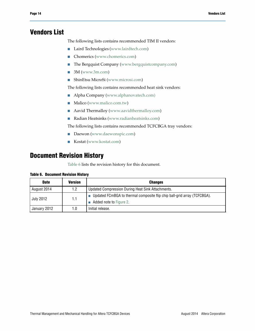
Document Revision HistoryTable 6 lists the revision history for this document.
Table 6. Document Revision History
Date Version Changes
August 2014 1.2 Updated Compression During Heat Sink Attachments.
July 2012 1.1■ Updated FCmBGA to thermal composite flip chip ball-grid array (TCFCBGA).
■ Added note to Figure 2.
January 2012 1.0 Initial release.
Thermal Management and Mechanical Handling for Altera TCFCBGA Devices August 2014 Altera Corporation