analysis and design of hybrid electric regional turboprop ... · analysis and design of hybrid...
TRANSCRIPT

ORIGINAL PAPER
Analysis and design of hybrid electric regional turboprop aircraft
Mark Voskuijl1 • Joris van Bogaert1 • Arvind G. Rao1
Received: 10 April 2017 / Revised: 22 September 2017 / Accepted: 10 October 2017 / Published online: 31 October 2017
� The Author(s) 2017. This article is an open access publication
Abstract The potential environmental benefits of hybrid
electric regional turboprop aircraft in terms of fuel con-
sumption are investigated. Lithium–air batteries are used as
energy source in combination with conventional fuel. A
validated design and analysis framework is extended with
sizing and analysis modules for hybrid electric propulsion
system components. In addition, a modified Breguet range
equation, suitable for hybrid electric aircraft, is introduced.
The results quantify the limits in range and performance for
this type of aircraft as a function of battery technology
level. A typical design for 70 passengers with a design
range of 1528 km, based on batteries with a specific energy
of 1000 Wh/kg, providing 34% of the shaft power
throughout the mission, yields a reduction in emissions by
28%.
Keywords Hybrid electric propulsion � Range equation �Aircraft design � Mission analysis
List of symbols
CL Lift coefficient [–]
CD Drag coefficient [–]
cP Power-specific fuel consumption [m-1]
cT Thrust-specific fuel consumption [s-1]
E Energy [J]
g Gravitational acceleration [m/s2]
H Energy per unit fuel or battery [J/kg]
p Power density [kW/kg]
P Power [J/s]
Pa Power available [J/s]
Pbr Shaft power [J/s]
R Range [m]
S Power split [–]
t Time [s]
T Thrust [N]
V Airspeed [m/s]
W Weight [N]
g Efficiency [–]
U Supplied power ratio [–]
w Hybridization factor [–]
Indices and subscripts
bat Batteries
cryo Cryocooler
em Electric motor
inv Inverter
prop Propeller
Abbreviation
MTOM Maximum take-off mass
1 Introduction
The potential for hybrid electric or even full electric
commercial aircraft has received a great deal of attention
over the past years. The industry is currently in the process
of adopting the ‘more-electric’ aircraft in which various
aircraft systems (pneumatic and hydraulic) are replaced by
electric systems [1–5]. Various recent studies highlight the
potential of (partly) using electric power for propulsion.
This opens a realm of new propulsion system architectures
and even new aircraft configurations. Three basic
& Mark Voskuijl
1 Delft University of Technology, Kluyverweg 1,
2629 HS Delft, The Netherlands
123
CEAS Aeronaut J (2018) 9:15–25
https://doi.org/10.1007/s13272-017-0272-1

approaches to the use of electric power for propulsion can
be distinguished.
• Batteries as energy source to (partly) replace fossil
fuels.
• Provide electric power at specific flight phases to limit
the variation in the gas turbine operability.
• Novel aircraft configurations (e.g., distributed
propulsion).
First of all, batteries can be used as an energy source just
like conventional fuel. The fundamental challenge in using
batteries as an energy source for propulsion is the low
specific energy of batteries compared to the high specific
energy of conventional jet fuel. The specific energies of
state-of-the-art batteries are in the order of 100–200 Wh/kg
at cell level, whereas gasoline has a specific energy of
approximately 13,000 Wh/kg. Lithium–air batteries, how-
ever, show great promise with a theoretical specific energy
of 11,680 Wh/kg [6]. Many significant challenges have to
be overcome before even a small part of this theoretical
value can be achieved in reality. Consequentially, the use
of batteries as energy source is at the moment only feasible
for small aircraft, which have a low weight and limited
range. Currently, there are already various flying demon-
strators and production versions of manned full electric
general aviation aircraft. Several recent small electric air-
craft initiatives are described by Wells [7]. A realistic
design procedure for small full electric aircraft was
recently introduced by Riboldi and Gualdoni [8]. Studies
for larger aircraft are usually based on estimates of the
specific energy of future batteries. Pornet et al. [9] inves-
tigated the use of batteries as energy source alongside
conventional jet fuel as a retrofit for short-to-medium-
range single-aisle turbofan aircraft. They conclude that the
use of batteries with an energy density of 1500 Wh/kg as an
energy source can provide a large block fuel reduction
(- 16%) on short-range missions in case the energy ratio
of fuel and batteries is 82–18%. Further analysis by Pornet
et al. demonstrates that batteries with an energy density
below 1000 Wh/kg provide no significant fuel savings at
all. A similar study was performed by Friedrich and
Robertson [10] in which a Boeing 737–800 was retrofitted
with a hybrid electric propulsion system. Assuming a
specific energy of 750 Wh/kg, a 10.4% fuel saving was
computed on a 2 h mission. The energy stored in the bat-
teries is 6% of the total energy (fuel and batteries). This
comes at the expense of an increase in aircraft weight of
approximately 10,000 kg. This added weight was, how-
ever, not accounted for by a structural redesign of the
aircraft. The feasibility of a full electric regional aircraft
concept designated VOLTAIR was investigated by Stuckl
et al. [11]. Their calculations demonstrate that it is feasible
to design a full electric regional aircraft for 70 passengers
with a design range of 1667 km if batteries with a specific
energy of 750 Wh/kg are available. The VOLTAIR design,
however, is also based on the beneficial effects of other
technologies; (1) a propulsive fuselage configuration fea-
turing boundary layer ingestion, (2) a low slenderness
fuselage with reduced structural weight and (3) a 60%
natural laminar flow wing. These combined technologies
are claimed to yield a 25% improvement in energy effi-
ciency. The VOLTAIR aircraft design does not converge
for longer range missions or larger payloads, indicating a
physical limit in size for full electric regional aircraft. The
studies described above highlight that there is a limit in
aircraft size even when significant improvements in battery
technology are achieved. The use of batteries as energy
source alongside conventional fuel therefore shows the
most promise for the regional aircraft segment. Further-
more, the vast majority of air travel is conducted by
regional aircraft and short-to-medium-range single-aisle
jets [12]. At present, however, there are no research studies
on the use of batteries as energy source for regional tur-
boprop aircraft with a conventional configuration. A sum-
mary of current and future battery technology at both cell
and system level is shown in Fig. 1.
A second approach to the use of batteries for propulsion
is to provide additional power in specific mission phases
such as take-off and climb. By doing so, the conventional
gas turbines can be optimized for a single flight condition
(cruise). As a result, they can be smaller (lower weight) and
more efficient. It was demonstrated by Perullo and Mavris
[13] that it is important to combine the mission optimiza-
tion, aimed at finding the optimum transient power split,
with the aircraft design optimization. Ang et al. [14]
investigated the benefits of this approach for a hybrid
electric version of an Airbus A320. It is demonstrated that
for short-range missions of 1000 km a fuel burn saving of
7.5% can be achieved when the engine is scaled to 90%
0 100 200 300 400 500 600 700 800
Specific Energy Density [Wh(total)/kg]
0
100
200
300
400
500
600
700
800
900
1000
1100
Spe
cific
Ene
rgy
Den
sity
[Wh(
tota
l)/lit
er]
Current Li-ion (cell)Current Li-ion (system)
Optimistic Li-ion* (cell)
Optimistic Li-ion* (system)
Optimistic Li-Sulfur* (cell)
Optimistic Li-Sulfur* (system)
Optimistic Li-Air* (cell)
Optimistic Li-Air* (system)* Assumes Li-Metal negative
Fig. 1 High energy batteries cell and system level comparison
16 M. Voskuijl et al.
123

and electric power is used to assist the take-off and climb
phases (with 25 and 14% electric power, respectively).
These estimates were based on batteries with a specific
energy of 600 Wh/kg.
Finally, having a hybrid electric propulsion system
makes it possible to separate the engine from the propulsor
and thereby new aircraft configurations become feasible.
An example is the NASA N3-X design of a hybrid wing
body aircraft with a turboelectric distributed propulsion
system [15]. Distributed propulsion can be used to enhance
the efficiency by wake-filling and boundary layer ingestion.
In addition, a higher integration of the propulsion system
and airframe can lead to a lower structural weight. Fur-
thermore, in case a single core engine is used to power
multiple electrically driven fans, a higher effective bypass
ratio can be achieved [16]. This is applied for example in
the Airbus-Rolls Royce E-Thrust concept [17].
It should be noted that the three main approaches to the
use of hybrid electric propulsion described above are
complementary and can be combined. The main objective
of this research study is to investigate the potential fuel
burn savings specifically for regional turboprop aircraft
with a conventional configuration in case the energy
source is a combination of conventional fuel and batteries.
The identification of the optimal ratio of gas turbine
power and electric power throughout the mission is
included in the design study. A key element in the anal-
ysis of hybrid electric regional aircraft is therefore an
accurate mission analysis. For the first initial design
iterations, an analytical approach to mission analysis is
used. The traditional Breguet range equation is, however,
not suitable for hybrid electric aircraft which use batteries
as an energy source. The second objective of this study is
therefore to introduce a new range equation, suitable for
hybrid electric aircraft within the context of the flying
strategies and design framework used. Alternative for-
mulations of (hybrid) electric range equations can be
found in references [18, 19]. For subsequent design iter-
ations, detailed flight path simulations are used. Ideally,
the objective of the design optimization should be to
minimize emissions or direct operating costs in relation to
emissions. Practically, it is difficult to design for costs as
these depend on the economic situation. In conventional
aircraft design, the maximum take-off mass is therefore
often chosen as objective. This is not a feasible option in
the current study since the battery weight is very high.
Therefore, fuel burn is chosen as optimization target. It
should be noted that the environmental benefit of hybrid
electric regional turboprop aircraft as described in this
paper is only achieved when the energy stored in the
batteries is created by renewable energy sources. The
source of energy for the batteries is considered to be out
of the scope of the current study.
The structure of this paper is as follows. First, an
existing regional turboprop aircraft will be selected as a
reference. Next, a hybrid electric propulsion system
architecture will be defined for this aircraft. This includes a
description of the hybrid electric propulsion system
parameters. The overall design methodology will be dis-
cussed subsequently. For validation purposes, this design
method will first be used to design a conventional turbo-
prop aircraft with the same top-level aircraft requirements
as the reference aircraft. After validation, the design
method will be used to explore the design space ranging
from 100% conventional fuel to full electric propulsion.
This will be done for various design ranges and battery
technology levels. A single hybrid electric aircraft design
which shows most promise in terms of fuel savings and
practical feasibility will finally be selected and investigated
in more detail. Finally, conclusions and recommendations
are made.
2 Hybrid electric regional aircraft architecture
2.1 Reference aircraft
The ATR-72-600 is selected as reference aircraft. At pre-
sent, more than 800 aircraft have been produced. It is a
stretched version of the ATR-42 and the standard config-
uration can transport 70 passengers over a design range of
1528 km. The maximum cruise speed is 510 kts (true air-
speed) and the maximum operating altitude equals 7600 m.
It features two Pratt and Whitney PW 127 M engines, each
delivering 2500 maximum continuous shaft horsepower.
The propellers have six blades and a diameter of 3.93 m.
2.2 Hybrid electric propulsion system architecture
Various distinct hybrid electric propulsion system archi-
tectures are possible [20]. The most commonly used are the
series hybrid architecture and the parallel hybrid architec-
ture. For road vehicle applications, the series hybrid
architecture has the lowest fuel consumption [21]. How-
ever, it has a larger weight than a parallel architecture,
which is especially important in aerospace applications
[22]. In a design study by Friedrich and Robinson, which
was limited to light aircraft, it was demonstrated that the
parallel configuration provides the highest efficiency for
aerospace applications [23]. For the aforementioned rea-
sons, the parallel configuration is selected as solution for
hybrid electric regional aircraft. A schematic representa-
tion of the system is provided in Fig. 2. Fuel is used to
power a turboshaft engine, and batteries are used to power
an electric motor. Both turboshaft engine and electric
motor power the drive train coupled to the propellers.
Analysis and design of hybrid electric regional turboprop aircraft 17
123

It is essential to have accurate data representing the
weight and efficiency of all elements in the propulsion
system. Because lithium–air batteries have by far the
largest theoretical specific energy [6], this type is chosen
for the aircraft design. Design studies will be conducted
for a range in battery-specific energy of 750–1500 Wh/
kg. The lower boundary of 750 Wh/kg is chosen because
various studies have indicated that this value is needed
at least for hybrid electric aircraft to be a realistic option
[8, 24]. With present lithium–air batteries (the best
reported laboratory cell has a specific energy of 363 Wh/
kg [25]), this is by far not possible and it is estimated
that batteries with an energy density of 750 Wh/kg will
most likely not be available before the year 2035 [26]. A
notable feature of these batteries is that they slightly
increase in weight during operation [6]. For the cell
voltages, it is assumed that they have a high voltage in
the order of 10 kV in order to minimize transmission
losses. Current intensities of 50–100 A are envisioned.
Note that the cell voltage and current intensity does not
affect the design process reported in this research study.
The main parameters of the hybrid electric propulsion
system are summarized in Table 1.
The electric motor power density is a conservative
estimate based upon predictions reported in references
[28–30]. According to NASA, a cryocooler is expected to
have a power requirement of 0.16% of the maximum rated
power output of the electric motor [29]. However, a more
conservative value of 0.45% is chosen. The power density
of the cryocooler is based on the work by Ashcraft et al.
[29]. Since high-temperature superconducting motors
require AC power, an inverter is needed [30]. Aluminum
cables with a high voltage (6 kV) are used for the wiring.
This relative high voltage is needed to reduce the cable
diameter. Furthermore, aluminum cables have a lower
weight than copper cables for the same voltage and current.
The weight estimation is a function of current for a cable
rated at 6 kV and is based on commercial off the shelf
products presently available [31]. An impression of the
location of the hybrid electric propulsion system compo-
nents in the aircraft is presented in Fig. 3.
3 Design methodology
For the design and analysis of the hybrid electric regional
aircraft, a software framework designated as initiator, is
used [32]. This framework is a design and analysis method
suitable for both conventional and unconventional aircraft.
It is based on a combination of physics-based analyses and
empirical methods. This method has been verified in earlier
studies for various turbofan aircraft. For the purpose of the
current work, the method has been first extended with
sizing modules for turboprop engines. The sizing of the gas
turbine and propeller is based on well-established empirical
relations [33, 34]. Realistic variations of fuel flow and
maximum power with altitude and airspeed are included in
the propulsion system analysis. An introduction to turbo-
prop generalized performance can be found in [35]. An
alternative design and sizing approach for hybrid electric
aircraft is reported in [36]. As a first step after
+ -
Turbosha�Engine
Inverter Electric motor
Pbat Pbat,o�ake
Pbat – Pbat,o�akeηbat
Pa (=TV)
Wiringηinv ηwiring
Pinv Pwiring
ηem
Pbr,electric
Pbr,gasturbinePbr,total
+
+Pfuel
Fuel
Ba�eries
ηgas
Propellers
ηprop
Fig. 2 Parallel hybrid electric propulsion system architecture
Table 1 Hybrid electric
propulsion system parametersParameter Value Source
Lithium–air battery-specific energy range [Wh/kg] 750–1500 Design choice
Lithium–air battery mass variation [kg/Wh] 0.000192 [6]
Efficiency batteries gbat [–] 0.95
Efficiency electric motor (excluding cryocooler), gem [–] 0.98 [27]
Efficiency inverter ginv [–] 0.98 [28]
Efficiency wiring, gwiring [–] 0.99
Power density electric motor, pem [kW/kg] 15 [29, 30]
Power density inverter, pinv [kW/kg] 20 [28]
Power density cryocooler, pcryo [kW/kg] 0.33 [29]
Cryocooler power requirement [% of max. electric motor power output] 0.45 [29]
Ucable 6 kV Design choice
18 M. Voskuijl et al.
123
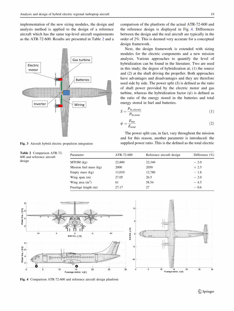
implementation of the new sizing modules, the design and
analysis method is applied to the design of a reference
aircraft which has the same top-level aircraft requirements
as the ATR-72-600. Results are presented in Table 2 and a
comparison of the planform of the actual ATR-72-600 and
the reference design is displayed in Fig. 4. Differences
between the design and the real aircraft are typically in the
order of 2%. This is deemed very accurate for a conceptual
design framework.
Next, the design framework is extended with sizing
modules for the electric components and a new mission
analysis. Various approaches to quantify the level of
hybridization can be found in the literature. Two are used
in this study; the degree of hybridization at; (1) the source
and (2) at the shaft driving the propeller. Both approaches
have advantages and disadvantages and they are therefore
used side by side. The power split (S) is defined as the ratio
of shaft power provided by the electric motor and gas
turbine, whereas the hybridization factor (w) is defined as
the ratio of the energy stored in the batteries and total
energy stored in fuel and batteries.
S ¼ Pbr;electric
Pbr;totalð1Þ
w ¼ Ebat
Etotal
ð2Þ
The power split can, in fact, vary throughout the mission
and for this reason, another parameter is introduced: the
supplied power ratio. This is the defined as the total electric
Inverter
Ba�eries
Gas turbineElectric motor
Wiring
Fig. 3 Aircraft hybrid electric propulsion integration
Table 2 Comparison ATR-72-
600 and reference aircraft
design
Parameter ATR-72-600 Reference aircraft design Difference (%)
MTOM (kg) 22,800 22,340 - 2.0
Mission fuel mass (kg) 2000 2050 ? 2.5
Empty mass (kg) 13,010 12,780 - 1.8
Wing span (m) 27.05 26.5 - 2.0
Wing area (m2) 61 58.54 - 4.5
Fuselage length (m) 27.17 27 - 0.6
Fig. 4 Comparison ATR-72-600 and reference aircraft design planform
Analysis and design of hybrid electric regional turboprop aircraft 19
123

motor power integrated over the mission in relation to the
total shaft power integrated over the mission.
U ¼RPbr;electricRPbr;total
ð3Þ
For all definitions, a value of zero represents a con-
ventional aircraft and a value of 1 represents a full electric
aircraft. Using the first two definitions, an analytical hybrid
electric range equation can be derived (see Appendix).
Rhybrid ¼gprop
g cPHfuel
g1� Sð Þ þ S
gelec
� �CL
CD
HbatHfuel
wHfuel þ 1� wð ÞHbatð Þ
ln
wHfuelþ 1�wð ÞHbatð ÞHbatHfuel
gEstart þWempty þWpayload
Wempty þWpayload
!
ð4Þ
Note that this equation reduces to the traditional Breguet
range equation in case the power split and hybridization
factor are set to zero. Furthermore, since the final energy is
zero at the end of the cruise flight (in case only the cruise
flight segment is considered and no reserve fuel or energy
is taken into account), the power split and hybridization
factor are directly related to each other. For a full electric
aircraft, the power split and hybridization factor are both 1.
In these scenarios, the range equation becomes:
Conventional S ¼ w ¼ 0ð Þ :
R ¼gpropcP
CL
CD
lnWfuel þWempty þWpayload
Wempty þWpayload
� � ð5Þ
Full electric S ¼ w ¼ 1ð Þ :
R ¼ gelecHbat
ggprop
CL
CD
lnWbat þWempty þWpayload
Wempty þWpayload
� �
:
ð6Þ
Alternative analytical formulations of range for (hybrid)
electric aircraft can be found in [18, 19]. The analytical
range equation presented above is used for the first design
iterations. For later design iterations, a more accurate
mission analysis is conducted based on numerical flight
path simulations. In that case, it is possible to vary and
optimize the power split throughout the mission in order to
obtain minimum emissions. In the present work, two
strategies are investigated:
• Constant power split.
• Constant operating mode of gas turbine.
In the first strategy, the ratio of the power setting
(throttle) of the gas turbine and the electric motor is
fixed. In the second strategy, the input to the gas turbine
is predefined and this engine runs at its most efficient
point during the majority of the mission. The rest of the
power is delivered by the electric motor. An example
mission simulation with the constant power split strategy
is presented in Fig. 5. Strictly speaking, there is only a
constant split between the throttle setting of the electric
motor and the gas turbine. The power delivered by the
gas turbine, however, depends on the flight altitude (air
density and altitude) and therefore shows variations
during climb and descent, which are not present for the
power delivered by the electric motor. The electric
motor throttle could have been varied simultaneously in
order to achieve a constant power split at the shaft
instead of a constant split in throttle setting. Practically,
the approach of having a constant throttle split is more
straightforward to implement in the automatic control
laws of an aircraft. Furthermore, this approach results in
a slightly improved climb performance. Furthermore, it
should be noted that the mission simulation includes
both the take-off and landing phases. However, since the
distance covered in take-off and landing is small com-
pared to the other mission phases, this is not represented
in Fig. 5. The required take-off power is based on the
power loading diagram traditionally used conceptual/
preliminary aircraft design studies. The power setting is
maximum during take-off and the power split is taken
into account. Important parameters such as the addition
of landing gear drag and friction of the tires are also
included in the take-off and landing simulation. It is
assumed that the batteries can deal with the power peak
requested during take-off which results in a high current
intensity. This is can be a rather crude assumption for
the constant operating mode strategy.
For all aircraft designs evaluated in this research study,
the operating mode has only a very small effect on the final
result in terms of MTOM and fuel consumption. This
justifies to a certain extent the assumption that the power
peak can be delivered by the batteries. It is a recommen-
dation for future research to investigate the effect of this
assumption this further. For sake of brevity, all results
presented in the next section are therefore based on a single
operating mode (the constant power split). It is recom-
mended for future research to perform a true mission
optimization in which electric motor power, gas turbine
power airspeed and altitude are varied throughout the flight
in order to minimize emissions subject to realistic operat-
ing constraints. An example of such an optimization study
is reported by Perullo and Mavris [13]. Such a study is
more feasible for a single or limited number of designs. In
the current study, this is not feasible since a large design
space is explored and each single converged design
requires a significant computational effort as all disciplines
are involved.
20 M. Voskuijl et al.
123

4 Results and discussion
The effect of the power split and the specific energy of the
batteries on the fuel mass, battery mass and total aircraft
mass is investigated using the design framework. Results
are presented in Figs. 6 and 7.
The battery mass increases significantly with a higher
power split and fuel mass decreases as expected from
Eq. 3. The trend lines in Figs. 6 stop when the design does
not converge anymore, indicating a hard limit to the design
space based on battery technology level. The complete
aircraft design is modified when the weight (and volume)
of components in the propulsion system change due to the
well-known snowball effect. The maximum take-off mass
for various power splits and battery technology levels is
visualized in Fig. 8. The mass of the hybrid electric power
train components, excluding the energy source (batteries
and fuel) and the propellers, is represented in Fig. 9.
Compared to the masses of the energy sources, the electric
components in the power train also have a significant effect
on the overall mass. The ratio of the masses of the com-
bined power train systems over the weight of the energy
sources, however, decreases. In all scenarios, the total mass
of the hybrid electric power train is larger than the mass of
two conventional gas turbines.
In all the results presented so far, the design range was
fixed to 1528 km. The benefits of a hybrid electric
propulsion system are also explored for various design
ranges and power splits. This is done assuming the avail-
ability of batteries with a specific energy of 1000 Wh/kg.
Results are presented in Fig. 10. In this figure, the feasible
design limit is highlighted. This demonstrates that it is
Fig. 5 Mission simulation
example for mission range of
1528 km with extended range
for diversion to alternate airport
(take-off and landing are
included but not visible)
Fig. 6 Battery mass (left) and ratio of battery mass and MTOM as a function of supplied power ratio
Analysis and design of hybrid electric regional turboprop aircraft 21
123
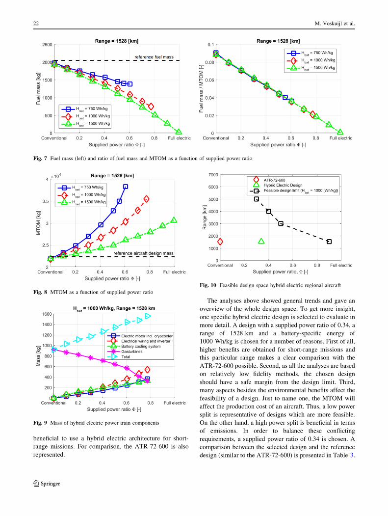
beneficial to use a hybrid electric architecture for short-
range missions. For comparison, the ATR-72-600 is also
represented.
The analyses above showed general trends and gave an
overview of the whole design space. To get more insight,
one specific hybrid electric design is selected to evaluate in
more detail. A design with a supplied power ratio of 0.34, a
range of 1528 km and a battery-specific energy of
1000 Wh/kg is chosen for a number of reasons. First of all,
higher benefits are obtained for short-range missions and
this particular range makes a clear comparison with the
ATR-72-600 possible. Second, as all the analyses are based
on relatively low fidelity methods, the chosen design
should have a safe margin from the design limit. Third,
many aspects besides the environmental benefits affect the
feasibility of a design. Just to name one, the MTOM will
affect the production cost of an aircraft. Thus, a low power
split is representative of designs which are more feasible.
On the other hand, a high power split is beneficial in terms
of emissions. In order to balance these conflicting
requirements, a supplied power ratio of 0.34 is chosen. A
comparison between the selected design and the reference
design (similar to the ATR-72-600) is presented in Table 3.
Fig. 7 Fuel mass (left) and ratio of fuel mass and MTOM as a function of supplied power ratio
Fig. 8 MTOM as a function of supplied power ratio
Fig. 9 Mass of hybrid electric power train components
Fig. 10 Feasible design space hybrid electric regional aircraft
22 M. Voskuijl et al.
123

The total mission fuel needed is reduced by 28%. This
comes at the expense of a larger aircraft in terms of MTOM
(? 14%) and wing area. The fuselage, however, is nearly
identical since it holds the same number of passengers.
From this it can be concluded that there is definitely the
possibility of drastic fuel weight reduction by using the
hybrid electric aircraft concept (up to about 30% power
split), provided that there is sufficient technological pro-
gress, particularly pertaining to battery-specific energy
density. Although outside of the scope of this research
study, it should be noted that the energy in the batteries is
generated at some point. This should be done using
renewable energy sources. Otherwise, the fuel benefits on
aircraft level are diminished. Furthermore, the batteries are
not recharged in flight and should therefore be replaced
quickly on airports. This operational process could have a
significant impact on the turn around time of the aircraft
should be investigated further.
5 Conclusions and recommendations
The potential environmental benefits of a hybrid electric
propulsion system for regional turboprop aircraft are
investigated. Lithium–air batteries are used as primary
energy source alongside conventional fuel in a parallel
hybrid electric propulsion system architecture. A largely
physics-based analysis and design tool is used to explore
the design space, assuming a future battery technology
level with specific energies ranging from 750 to 1500 Wh/
kg. The tool is validated for conventional turboprop air-
craft. The feasible design space in terms of mission range
and level of hybridization is quantified. The high weight of
batteries compared to fuel has a large effect on the designs.
Other systems such as battery cooling, wiring have a sig-
nificant impact on the overall aircraft weight and should,
therefore, be taken into account as well. Furthermore, it is
essential to tightly couple an accurate mission analysis with
the aircraft design procedure. A new range equation
suitable for hybrid electric aircraft is introduced. Results
demonstrate that hybrid electric propulsion can provide a
significant reduction in emissions for turboprop aircraft
designed for short-range missions (1528 km). A typical
design which has 34% electric shaft power requires 28%
less mission fuel at the expense of a larger aircraft in terms
of weight and wing area. An additional benefits of this
configuration which were not quantified in the current
research, are a reduction in local emissions at the airport
and a noise reduction during take-off and landing.
It is recommended to further investigate the operational
consequences of operating regional aircraft with large
battery packs on airports. Another recommendation is to
perform detailed mission optimization studies to determine
optimal flying strategies for hybrid electric regional air-
craft. Furthermore, the safety of such an aircraft is of
paramount importance and consequences for the certifica-
tion process should be investigated. Finally, the results rely
on significant improvements in battery technology. It is
therefore essential to tackle the associated challenges in
battery development.
Open Access This article is distributed under the terms of the
Creative Commons Attribution 4.0 International License (http://crea
tivecommons.org/licenses/by/4.0/), which permits unrestricted use,
distribution, and reproduction in any medium, provided you give
appropriate credit to the original author(s) and the source, provide a
link to the Creative Commons license, and indicate if changes were
made.
Appendix
The range of a conventional fuel powered aircraft (zero
wind conditions, thrust vector parallel to the airspeed
vector) can be computed based on the Breguet range
equation.
R ¼ZWstart
Wfinal
V
cT
CL
CD
1
WdW ð7Þ
Table 3 Comparison reference and selected hybrid electric aircraft design (U = 0.34)
Parameter Reference aircraft Hybrid electric aircraft Difference
MTOM (kg) 22,340 25,470 ? 14%
Mission fuel mass (kg) 2050 1470 - 28%
Battery mass (kg) 0 2948 n/a
Battery energy density (Wh/kg) n/a 1000 n/a
Empty mass (kg) 12,780 13,552 ? 6%
Total energy stored in batteries and fuel (MWh) 26.19 21.73 - 17%
Wing span (m) 26.5 28.8 ? 8.7%
Wing area (m2) 58.54 69.1 ? 18%
Fuselage length 27 27 0%
Analysis and design of hybrid electric regional turboprop aircraft 23
123

The solution to the integral depends on the flying
strategy used (e.g., gradual climb at constant airspeed and
angle of attack) and the models used to represent the
propulsion system and the aerodynamic characteristics.
Solutions to the most common flying strategies can be
found in many standard text books on aircraft performance.
The range equation is based on the fact that weight grad-
ually changes throughout the flight, hence the integration
over the aircraft weight. Therefore, the range equation
cannot be applied to aircraft which (partly) use batteries as
energy supply. Fundamentally, the range can be deter-
mined by integrating speed over time.
R ¼Ztfinal
tstart
Vdt ð8Þ
The energy stored in batteries and fuel can be related to the
time to solve this. As time progresses, the energy stored in the
batteries or as fuel reduces. The power (energy per second)
used is the summation of battery power and fuel power.
dE
dt¼ dEfuel
dtþ dEbat
dtð9Þ
The time rate of change of the energy stored in the fuel
can be related to the fuel flow and the energy density of the
fuel. Furthermore, the shaft power delivered by the tur-
boshaft engine is related to the fuel flow through the
power-specific fuel consumption.
F ¼ � dWfuel
dt¼ � g
Hfuel
dEfuel
dtð10Þ
F ¼ cPPbr;gasturbine ð11Þ
The power split defines the relation of the shaft power
delivered by the turboshaft engine to the total shaft power
delivered to the propeller. The efficiency of the propeller
determines how much of the shaft power is transformed
into power available.
Pbr;gasturbine ¼ 1� Sð ÞPbr;total ¼ 1� Sð Þ Pa
gpropð12Þ
Thus, the change of energy stored by means of fuel can
be expressed as a function of power available.
dEfuel
dt¼ � cE
gprop
Hfuel
g1� Sð ÞPa ð13Þ
Along the same lines, the energy stored in the batteries
can be expressed in terms of the power available.
dEbat
dt¼ �Pbr;electric
gelec¼ � S
gelecgpropPa ð14Þ
By combining Eqs. 13 and 14, an equation for the
change of total energy with time is obtained.
dE
dt¼ � cP
gprop
Hfuel
g1� Sð Þ þ S
gelecgprop
!
Pa ð15Þ
In quasi-steady, quasi-rectilinear flight, thrust must
equal drag and lift equals weight. Assuming the thrust
vector is parallel to the airspeed vector, Eq. 16 can be
determined.
Pa ¼ DV ¼ CD
CL
WV ð16Þ
Now the basic range equation for hybrid electric cruise
flight can be created by combining Eqs. 8, 15 and 16.
R ¼ZEstart
Efinal
1
cPgprop
Hfuel
g1� Sð Þ þ S
gelecgprop
� �CL
CD
1
WdE ð17Þ
It is assumed that the power split and angle of attack are
kept constant throughout the cruise flight. Furthermore, for
the range of flight speeds and altitudes of interest, the
power-specific fuel consumption, propeller efficiency and
the combined electric efficiency are considered constant. In
case of a flight at constant airspeed, this results in a gradual
climb. Note that this climb is less steep than for conven-
tional aircraft. In the case of a full electric aircraft, it
becomes a horizontal flight profile.
R ¼ 1
cPgprop
Hfuel
g1� Sð Þ þ S
gelecgprop
� �CL
CD
ZEstart
Efinal
1
WdE ð18Þ
The weight term is left in the integral since it is a
function of the energy. Both the battery weight and fuel
weight can be expressed in terms of energy based on their
respective energy densities.
W ¼ Wempty þWpayload þWbat þWfuel ð19Þ
W ¼ EbatHfuel þ EfuelHbat
HbatHfuel
gþWempty þWpayload ð20Þ
Using the hybridization factor, the equation can be
rewritten as a function of total energy.
W ¼ wHfuel þ 1� wð ÞHbat
HbatHfuel
gE þWempty þWpayload ð21Þ
The energy densities, payload weight, empty weight and
hybridization factor are constant. Hence, the final range
equation can be derived by solving the integral.
Rhybrid ¼gprop
g cPHfuel
g1� Sð Þ þ S
gelec
� �CL
CD
HbatHfuel
wHfuel þ 1� wð ÞHbatð Þ
ln
wHfuelþ 1�wð ÞHbatð ÞHbatHfuel
gEstart þWempty þWpayload
Wempty þWpayload
!
ð22Þ
24 M. Voskuijl et al.
123

References
1. Chakraborty, I., Mavris, D.N., Emeneth, M., Schneegans, A.: An
integrated approach to vehicle and subsystem sizing and analysis
for novel subsystem architectures. Proc. Inst. Mech. Eng. Part G
J. Aerosp. Eng. 230(3), 496–514 (2016)
2. Wheeler, P.W., Clare, J.C., Trentin, A., Bozhko, S.: An overview
of the more electrical aircraft. Proc. Inst. Mech. Eng. Part G J.
Aerosp. Eng. 227(4), 578–585 (2013)
3. Naayagi, R.T.: A review of more electric aircraft technology. In:
International Conference on Energy Efficient Technologies for
Sustainability, ICEETS, Nagercoil, India (2013)
4. Gandolfi, R., Pellegrini, L.F., de Oliveira Jr., S.: More electric
aircraft analysis using exergy as a design comparison tool. In:
48th AIAA Aerospace Sciences Meeting Including the New
Horizons Forum and Aerospace Exposition, Orlando (2010)
5. Moir, I., Seabridge, A.: Aircraft systems—mechanical, electrical
and avionics subsystems integration. 3rd edn. Wiley, Chichester,
England (2008)
6. Girishkumar, G., McCloskey, B., Luntz, A.C., Swanson, S.,
Wilke, W.: Lithium-air battery: promise and challenges. J. Phys.
Chem. Lett. 1(14), 2193–2203 (2010)
7. Wells, D.P.: NASA green flight challenge: conceptual design
approaches and technologies to enable 200 passenger miles per
gallon. In: 11th AIAA Aviat. Technol., Integr. and Operations
Conference, Virginia Beach, Virginia (2011)
8. Riboldi, C.E.D., Gualdoni, F.: An integrated approach to the
preliminary weight sizing of small electric aircraft. Aerosp. Sci.
Technol. 58, 134–139 (2016)
9. Pornet, C., Gologan, C., Vratny, P.C., Seitz, A., Schmitz, O.,
Isikveren, A.T., Hornung, M.: Methodology for sizing and per-
formance assessment of hybrid energy aircraft. J. Aircr. 52(1),341–352 (2015)
10. Friedrich, C., Robertson, P.A.: Hybrid-electric propulsion for
aircraft. J. Aircr. 52(1), 176–189 (2015)
11. Stuckl, S., van Toor, J., Lobentanzer, H.: VOLTAIR, the all-
electric propulsion concept platform—a vision for atmospheric
friendly flight. In: 28th International Congress of the Aeronauti-
cal Sciences, Brisbane, Australia (2012)
12. Bradley, M.K., Droney, C.K.: Subsonic ultra green aircraft
research: phase I final report. NASA NASA/CR–2011-216847
(2011)
13. Perullo, C., Mavris, D.: A review of hybrid-electric energy
management and its inclusion in vehicle sizing. Aircr. Eng.
Aerosp. Technol. Int. J. 86(6), 550–557 (2014)
14. Ang, A.: Integrated performance analysis of a parallel hybrid
electric propulsion system applied on short-range aircraft. Master
thesis, Delft University of Technology, Delft, The Netherlands
(2016)
15. Felder, J.L., Kim, H.D., Brown, G.V.: Turboelectric distributed
propulsion engine cycle analysis for hybrid-wing-body aircraft.
In: 47th AIAA Aerosp. Sciences Meeting including the New
Horizons Forum and Aerosp. Expos., Orlando (2009)
16. Kim, H.D.: Distributed propulsion vehicles. In: 27th International
Congress of the Aeronautical Sciences, Nice, France (2010)
17. Williamson, M.: Air Power: The rise of electric aircraft. Eng.
Technol. 9(10), 77–79 (2014)
18. Marwa, M., Martin, S.M., Martos, B.C., Anderson, R.P.: Analytic
and numeric forms for the performance of propeller-powered
electric and hybrid aircraft. AIAA SciTech Forum, Grapevine
(2017)
19. Traub, L.W.: Range and endurance estimates for battery-powered
aircraft. J. Aircr. 48(2), 703–707 (2011)
20. Chau, K.T., Wong, Y.S.: Overview of power management in
hybrid electric vehicles. Energy Convers. Manag. 43, 1953–1968(2002)
21. Cagatay Bayindir, K., Gozukucuk, M.A., Teke, A.: A compre-
hensive overview of hybrid electric vehicle: powertrain config-
urations, powertrain control techniques and electronic control
units. Energy Convers. Manag. 52(2), 1305–1313 (2012)
22. Hung, J.Y., Gonzales, L.F.: On parallel hybrid-electric propulsion
system for unmanned aerial vehicles. Prog. Aerosp. Sci. 52(1),1–17 (2012)
23. Friedrich, C., Robertson, P.A.: Design of a hybrid-electric
propulsion system for light aircraft. In: 14th AIAA Aviat.
Technol., Integration, and Operations Conference, Atlanta,
Georgia (2014)
24. Bradley, M.K., Droney, C.K.: Subsonic ultra green aircraft
research phase II: n ? 4 advanced concept development. NASA,
CR-2012-217556 (2012)
25. Kraytsberg, A., Ein-Eli, Y.: Review on Li-Air batteries—oppor-
tunities, limitations and perspective. J. Power Sources 196(3),886–893 (2011)
26. Rostek, P.: Hybrid electric propulsion—a Eur. initiative for
technol. development. In: Electr. and Hybrid Aerosp. Technol.
Symposium (E&H ATS), Bremen, Nov 17 (2015)
27. Schiferl, R., Flory, A., Livoti, W.C., Umans, S.D.: High-tem-
perature superconducting synchronous motors: economic issues
for industrial applications. IEEE Trans. Ind. Appl. 44(5),1376–1384 (2008)
28. Brown, G. V.: Weights and efficiencies of electric components of
a turboelectric aircraft propulsion system. In: 49th AIAA Aerosp.
Sciences Meeting including the New Horizons Forum and
Aerosp. Exposition, Orlando (2011)
29. Ashcraft, S.W., Padron, A.S., Pascioni, K.A., Stout, Jr., G.W.:
Review of propulsion technologies for N ? 3 subsonic vehicle
concepts. NASA TM—2011-217239 (2011)
30. Masson, P.J., Luongo, C.A.: High power density superconducting
motor for all-electric aircraft propulsion. IEEE Trans. Appl.
Supercond. 15(2), 2226–2229 (2005)
31. Anonymous.: Medium voltage power cables. Synergy Cables Ltd.
http://www.synergycables.com/index.php?show=484&show
type=attachment&focused=1 (2017). Accessed 30 Oct 2017
32. Elmendorp, R., Vos, R., La Rocca, G.: A conceptual design and
analysis method for conventional and unconventional airplanes.
In: 29th Congress of the International Council of the Aeronautical
Sciences, St. Petersburg, Russia (2014)
33. Raymer, D.P.: Aircraft design, a conceptual approach. 5th edn.
AIAA Education Series, Washington, DC (2012)
34. Roskam, J.: Airplane design part II: preliminary configuration
design and integration of the propulsion system. 5th edn. Design,
Analysis and Research Corporation, Lawrence, Kansas (2017)
35. Torenbeek, E.: Advanced aircraft design. Wiley, New York
(2013)
36. Isikveren, A.T., Kaiser, S., Pornet, C., Vratny, P.C.: Pre-design
strategies and sizing techniques for dual-energy aircraft. Aircr.
Eng. Aerosp. Technol. Int. J. 86(6), 525–542 (2014)
Analysis and design of hybrid electric regional turboprop aircraft 25
123