analysis and optimization of a curved transmit-receive
TRANSCRIPT

Analysis and Optimization of a CurvedTransmit-Receive Contoured Beam Reflectarray
Min Zhou, Stig B. Sørensen, Oscar Borries, and Erik JørgensenTICRA, Copenhagen, Denmark
Abstract—This paper presents the analysis and optimization ofa 1 meter single-layer curved contoured beam reflectarray in Ku-band. The curved reflectarray is designed to radiate a contouredbeam over a European coverage in both transmit and receivefrequency bands for dual linear polarization. For the analysis ofthe curved reflectarray, the spectral domain method of momentsassuming local periodicity is used, and its accuracy is verifiedby comparisons with full-wave method of moments simulations.For the optimization, a direct optimization approach where allthe array elements are simultaneously optimized is used. Theoptimized curved reflectarray is compared to the shaped reflector,and the comparison shows that the performance of the curvedreflectarray is identical to that of the shaped reflector.
Index Terms—reflectarrays, contoured beam, optimization,shaped reflectors, satellite applications
I. INTRODUCTION
Printed reflectarrays usually consist of a flat surface. Theyare light, easy and cheap to manufacture, and provide a way torealize low-cost high-gain antennas for space applications [1].For satellite broadcasting applications, where contoured beamsthat radiate certain geographical areas in a large frequencyband are required, the shaped reflector is the preferred choicefor most missions. Although the shaped reflector is based ona mature technology and has proven to be a reliable solution,the cost associated to its manufacturing is high. Consequently,satellite manufactures and space agencies are investigatingpossible cheaper solutions in the form of reflectarrays.
Contoured beam reflectarrays have been reported in variousworks, e.g., [2]–[4]. However, the bandwidth of the reflect-arrays presented in these works is only sufficient for eithertransmit (Tx) or receive (Rx) operation. In [5], a reflectarrayoperating in both Tx and Rx frequency bands was presented,the simulations show that the coverage gain requirements arefulfilled in more than 90% of the region in both frequencybands. A common feature of the reflectarrays presented in [2]–[5] is that they are designed using a phase-only optimizationapproach, which may result in sub-optimal designs sinceintermediate steps are required in the design process.
A direct optimization approach where all the array elementsare simultaneously optimized tends to produce improved de-signs. Such an approach was presented in [6]. Using the directoptimization approach, a single-layer planar contoured beamreflectarray, optimized for the same coverage requirements asin [5], was presented in [7]. This reflectarray fulfills all thecoverage requirements in both Tx and Rx frequency bandsand shows significantly better performance than previously
reported planar contoured beam reflectarrays. Despite exhibit-ing enhanced performance, this reflectarray did not reach theperformance of the shaped reflector, due to the bandwidthlimitations imposed by the differential spatial phase delay fromthe feed horn.
Several solutions have been proposed in the literature toalleviate the differential spatial phase delay, one of them beingthe use of advanced broadband elements in conjunction witha multi-faceted structure as suggested in, e.g., [8] and demon-strated in [4]. This solution is rather promising and it wasshown in [9] that the combination of the multi-faceted conceptand the direct optimization technique can yield reflectarrayswith performances that are close to that of the shaped reflector.However, a reflectarray with elements printed on a doublycurved surface has a number of distinct advantages comparedto its multi-faceted counterpart.
First, for a curved reflectarray, the spatial phase delay issueis further reduced compared to a multi-faceted reflectarrayand the bandwidth is mainly determined by the bandwidthof the individual array elements. Second, a large doublycurved surface is inherently stiffer and can thus be made morelightweight than the corresponding multi-faceted or planarcounterpart. Third, a curved reflectarray avoids the abruptsurface change at the joints of a multi-faceted reflectarraywhich can give rise to undesired RF effects. Finally, a curvedreflectarray is attractive compared to traditional shaped re-flectors due to the possibility of reusing a standard parabolicmould for multiple coverages and missions.
The concept of a curved reflectarray was first suggestedin [10] and later investigated in [11]. In the latter, a two-layer reflectarray consisting of varying-sized patches on aparabolic surface is presented. Although it was shown thatthe bandwidth was improved, the reflectarray was synthesizedusing a phase-only optimization technique and the analysisof the reflectarray is carried out with some rather crudegeometrical approximations, which do not take into accountthe curvature of the reflectarray.
In this work, we apply the direct optimization techniquefrom [6] to design and optimize a curved reflectarray to radiatea contoured beam in both Tx- and Rx frequency bands. Thereflectarray consists of single-layer elements of variable sizeprinted on a doubly curved surface and simulations show thatthe performance of the curved reflectarray is identical to thatof the shaped reflector.
0.10 -0.0 -0.100.15 0.10 0.05 -0.0 -0.05 -0.10 -0.15u
0.00
0.10
0.00
0.05
0.10
0.15
v
0.15 0.1 0.05 0 −0.05 −0.1 −0.150
0.05
0.1
0.15
0.2
u
v EU1
EU2
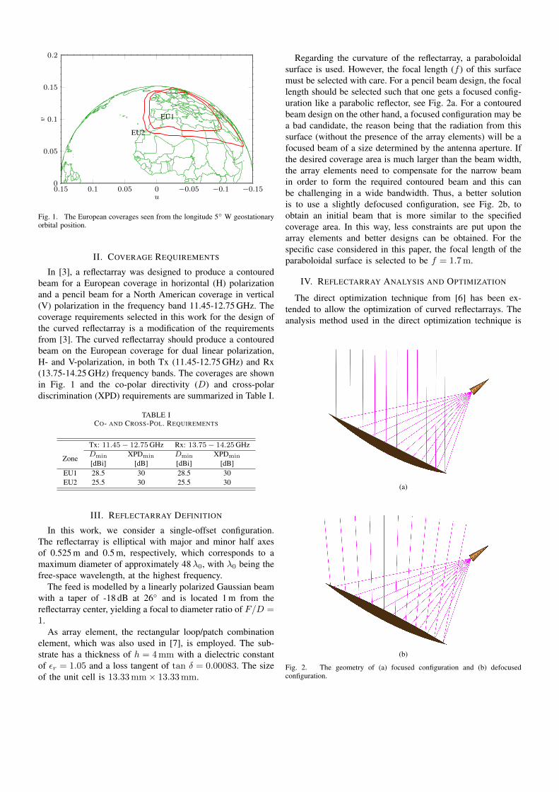
Fig. 1. The European coverages seen from the longitude 5◦ W geostationaryorbital position.
II. COVERAGE REQUIREMENTS
In [3], a reflectarray was designed to produce a contouredbeam for a European coverage in horizontal (H) polarizationand a pencil beam for a North American coverage in vertical(V) polarization in the frequency band 11.45-12.75 GHz. Thecoverage requirements selected in this work for the design ofthe curved reflectarray is a modification of the requirementsfrom [3]. The curved reflectarray should produce a contouredbeam on the European coverage for dual linear polarization,H- and V-polarization, in both Tx (11.45-12.75 GHz) and Rx(13.75-14.25 GHz) frequency bands. The coverages are shownin Fig. 1 and the co-polar directivity (D) and cross-polardiscrimination (XPD) requirements are summarized in Table I.
TABLE ICO- AND CROSS-POL. REQUIREMENTS
Tx: 11.45− 12.75GHz Rx: 13.75− 14.25GHz
Zone Dmin XPDmin Dmin XPDmin
[dBi] [dB] [dBi] [dB]EU1 28.5 30 28.5 30EU2 25.5 30 25.5 30
III. REFLECTARRAY DEFINITION
In this work, we consider a single-offset configuration.The reflectarray is elliptical with major and minor half axesof 0.525 m and 0.5 m, respectively, which corresponds to amaximum diameter of approximately 48λ0, with λ0 being thefree-space wavelength, at the highest frequency.
The feed is modelled by a linearly polarized Gaussian beamwith a taper of -18 dB at 26◦ and is located 1 m from thereflectarray center, yielding a focal to diameter ratio of F/D =1.
As array element, the rectangular loop/patch combinationelement, which was also used in [7], is employed. The sub-strate has a thickness of h = 4mm with a dielectric constantof εr = 1.05 and a loss tangent of tan δ = 0.00083. The sizeof the unit cell is 13.33mm× 13.33mm.
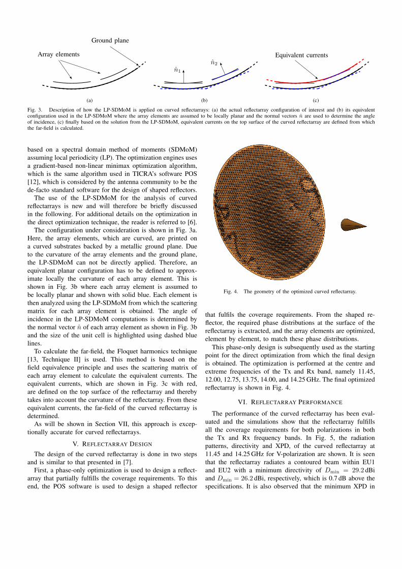
Regarding the curvature of the reflectarray, a paraboloidalsurface is used. However, the focal length (f ) of this surfacemust be selected with care. For a pencil beam design, the focallength should be selected such that one gets a focused config-uration like a parabolic reflector, see Fig. 2a. For a contouredbeam design on the other hand, a focused configuration may bea bad candidate, the reason being that the radiation from thissurface (without the presence of the array elements) will be afocused beam of a size determined by the antenna aperture. Ifthe desired coverage area is much larger than the beam width,the array elements need to compensate for the narrow beamin order to form the required contoured beam and this canbe challenging in a wide bandwidth. Thus, a better solutionis to use a slightly defocused configuration, see Fig. 2b, toobtain an initial beam that is more similar to the specifiedcoverage area. In this way, less constraints are put upon thearray elements and better designs can be obtained. For thespecific case considered in this paper, the focal length of theparaboloidal surface is selected to be f = 1.7m.
IV. REFLECTARRAY ANALYSIS AND OPTIMIZATION
The direct optimization technique from [6] has been ex-tended to allow the optimization of curved reflectarrays. Theanalysis method used in the direct optimization technique is
(a)
(b)
Fig. 2. The geometry of (a) focused configuration and (b) defocusedconfiguration.
Array elements
Ground plane
(a)
n̂1
n̂2
(b)
Equivalent currents
(c)
Fig. 3. Description of how the LP-SDMoM is applied on curved reflectarrays: (a) the actual reflectarray configuration of interest and (b) its equivalentconfiguration used in the LP-SDMoM where the array elements are assumed to be locally planar and the normal vectors n̂ are used to determine the angleof incidence, (c) finally based on the solution from the LP-SDMoM, equivalent currents on the top surface of the curved reflectarray are defined from whichthe far-field is calculated.
based on a spectral domain method of moments (SDMoM)assuming local periodicity (LP). The optimization engines usesa gradient-based non-linear minimax optimization algorithm,which is the same algorithm used in TICRA’s software POS[12], which is considered by the antenna community to be thede-facto standard software for the design of shaped reflectors.
The use of the LP-SDMoM for the analysis of curvedreflectarrays is new and will therefore be briefly discussedin the following. For additional details on the optimization inthe direct optimization technique, the reader is referred to [6].
The configuration under consideration is shown in Fig. 3a.Here, the array elements, which are curved, are printed ona curved substrates backed by a metallic ground plane. Dueto the curvature of the array elements and the ground plane,the LP-SDMoM can not be directly applied. Therefore, anequivalent planar configuration has to be defined to approx-imate locally the curvature of each array element. This isshown in Fig. 3b where each array element is assumed tobe locally planar and shown with solid blue. Each element isthen analyzed using the LP-SDMoM from which the scatteringmatrix for each array element is obtained. The angle ofincidence in the LP-SDMoM computations is determined bythe normal vector n̂ of each array element as shown in Fig. 3band the size of the unit cell is highlighted using dashed bluelines.
To calculate the far-field, the Floquet harmonics technique[13, Technique II] is used. This method is based on thefield equivalence principle and uses the scattering matrix ofeach array element to calculate the equivalent currents. Theequivalent currents, which are shown in Fig. 3c with red,are defined on the top surface of the reflectarray and therebytakes into account the curvature of the reflectarray. From theseequivalent currents, the far-field of the curved reflectarray isdetermined.
As will be shown in Section VII, this approach is excep-tionally accurate for curved reflectarrays.
V. REFLECTARRAY DESIGN
The design of the curved reflectarray is done in two stepsand is similar to that presented in [7].
First, a phase-only optimization is used to design a reflect-array that partially fulfills the coverage requirements. To thisend, the POS software is used to design a shaped reflector
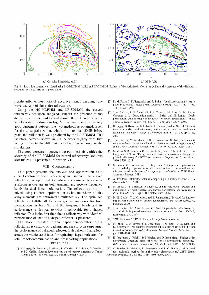
Fig. 4. The geometry of the optimized curved reflectarray.
that fulfils the coverage requirements. From the shaped re-flector, the required phase distributions at the surface of thereflectarray is extracted, and the array elements are optimized,element by element, to match these phase distributions.
This phase-only design is subsequently used as the startingpoint for the direct optimization from which the final designis obtained. The optimization is performed at the centre andextreme frequencies of the Tx and Rx band, namely 11.45,12.00, 12.75, 13.75, 14.00, and 14.25 GHz. The final optimizedreflectarray is shown in Fig. 4.
VI. REFLECTARRAY PERFORMANCE
The performance of the curved reflectarray has been eval-uated and the simulations show that the reflectarray fulfillsall the coverage requirements for both polarizations in boththe Tx and Rx frequency bands. In Fig. 5, the radiationpatterns, directivity and XPD, of the curved reflectarray at11.45 and 14.25 GHz for V-polarization are shown. It is seenthat the reflectarray radiates a contoured beam within EU1and EU2 with a minimum directivity of Dmin = 29.2 dBiand Dmin = 26.2 dBi, respectively, which is 0.7 dB above thespecifications. It is also observed that the minimum XPD in

29. 2
20. 0
20. 0
20. 0
15. 0
15. 0
15. 0
26. 2 26. 2
29. 2
0.15 0.1 0.05 0 −0.05 −0.1 −0.150
0.05
0.1
0.15
0.2
u
v EU1
EU2
(a) Co-polar Directivity (dBi), 11.45 GHz
30. 0
30. 0
30. 0
30. 026. 0
26. 0
26. 0
26. 0
0.15 0.1 0.05 0 −0.05 −0.1 −0.150
0.05
0.1
0.15
0.2
u
v EU1EU2
(b) XPD (dB), 11.45 GHz
29. 2
26. 2
26. 220. 0
20. 0
20. 0
15. 0
15. 0
15. 0
20. 0
0.15 0.1 0.05 0 −0.05 −0.1 −0.150
0.05
0.1
0.15
0.2
u
v EU1
EU2
(c) Co-polar Directivity (dBi), 14.25 GHz
30. 030. 0
30. 0
30. 0
26. 0
26. 0
26. 0
26. 0
26. 0
26. 0
0.15 0.1 0.05 0 −0.05 −0.1 −0.150
0.05
0.1
0.15
0.2
u
v EU1EU2
(d) XPD (dB), 14.25 GHz
Fig. 5. The radiation pattern in V-polarization for the optimized reflectarray at 11.45 and 14.25 GHz.
the european coverage is above 30 dB. The performance in H-polarization is practically identical and is therefore not shown.
The performance of the curved reflectarray is summarizedin Table II and compared to that of an equivalent sized shapedreflector optimized using POS with the same coverage require-ments. It is seen that the performance of the curved reflectarrayis practically identical to that of the shaped reflector.
It is, to our knowledge, the first time that the performanceof a reflectarray is shown to be identical to that of a shapedreflector and this can be considered a practical breakthrough.The good performance is attributed to the combination ofthe doubly curved structure, a suitable reflectarray element,and the direct optimization technique used to design thereflectarray. It is our belief that the inclusion of additionaldegrees of freedom in the array elements and the use of amore sophisticated starting point and optimization procedure,reflectarrays that surpass the performance of the shaped re-flector can be realized. This is subject to future investigation.
VII. VALIDATION BY FULL-WAVE SIMULATIONS
To validate the results presented above, we resort to full-wave simulations since measurements are not available.
TABLE IICOMPARISON BETWEEN REFLECTARRAY AND SHAPED REFLECTOR
Tx: 11.45-12.75 GHz Rx: 13.75-14.25 GHz
ZoneCurved Shaped Curved Shaped
Reflectarray Reflector Reflectarray ReflectorDmin XPDmin Dmin XPDmin Dmin XPDmin Dmin XPDmin
[dBi] [dB] [dBi] [dB] [dBi] [dB] [dBi] [dB]EU1 29.2 30.7 29.2 32.0 29.2 31.3 29.2 31.9EU2 26.2 30.7 26.2 30.7 26.2 30.7 26.2 30.7
For the present case, the dielectric constant of the substrateis εr = 1.05, i.e., close to that of free-space. Thus the substratecan be removed without significantly affecting the perfor-mance of the reflectarray. However, even in this case, due tothe size of the reflectarray, the number of unknowns requiredto achieve accurate results using a higher order (HO) Methodof Moments (MoM) [14] at 14.25GHz is approximately 1.3millions, resulting in a memory consumption of approximately6.2 TB. This is not computationally affordable, thus we resortto a multilevel fast multipole method (MLFMM) algorithm,which was recently presented in [15]. This implementationuses a HO discretization and reduces the memory requirements
29. 226. 2
20. 0
20. 0
15. 0
15. 0
15. 0
20. 0
15. 0
26. 2
0.15 0.1 0.05 0 −0.05 −0.1 −0.150
0.05
0.1
0.15
0.2
u
v EU1
EU2
(a) Co-polar Directivity (dBi)
30. 0
26. 0
26. 0
26. 0
26. 0
26. 0
30. 0
30. 0
30. 026. 0
30. 0
0.15 0.1 0.05 0 −0.05 −0.1 −0.150
0.05
0.1
0.15
0.2
u
v EU1
EU2
(b) XPD (dB)
Fig. 6. Radiation patterns calculated using HO-MLFMM (solid) and LP-SDMoM (dashed) of the optimized reflectarray (without the presence of the dielectricsubstrate) at 14.25 GHz in V-polarization.
significantly, without loss of accuracy, hence enabling full-wave analysis of the entire reflectarray.
Using the HO-MLFMM and LP-SDMoM, the curvedreflectarray has been analyzed, without the presence of thedielectric substrate, and the radiation pattern at 14.25 GHz forV-polarization is shown in Fig. 6. It is seen that an extremelygood agreement between the two methods is obtained. Evenfor the cross-polarization, which is more than 30 dB belowpeak, the radiation is well predicted by the LP-SDMoM. Theradiation patterns shown in Fig. 6 differ slightly with thatin Fig. 5 due to the different dielectric constant used in thesimulations.
The good agreement between the two methods verifies theaccuracy of the LP-SDMoM for curved reflectarrays and thusalso the results presented in Section VI.
VIII. CONCLUSIONS
This paper presents the analysis and optimization of acurved contoured beam reflectarray in Ku-band. The curvedreflectarray is optimized to radiate a contoured beam overa European overage in both transmit and receive frequencybands for dual linear polarization. The reflectarray is opti-mized using a direct optimization technique where all thearray elements are optimized simultaneously. The optimizedreflectarray fulfills all the coverage requirements for bothpolarizations in both Tx and Rx frequency bands and itsperformance is identical to what is achievable for a shapedreflector. This is the first time that a reflectarray with identicalperformance of that of a shaped reflector is presented.
The work presented in this paper demonstrates that areflectarray is capable of reaching, and maybe even surpassing,the performance of a shaped reflector. It also shows that reflect-arrays are viable candidates for replacing shaped reflectors forsatellite telecommunication and broadcasting applications.
REFERENCES
[1] H. Legay, D. Bresciani, E. Girard, R. Chiniard, E. Labiole, O. Vendier,and G. Caille, “Recent developments on reflectarray antennas at ThalesAlenia Space,” in Proc. EuCAP, Berlin, Germany, 2009.
[2] D. M. Pozar, S. D. Targonski, and R. Pokuls, “A shaped-beam microstrippatch reflectarray,” IEEE Trans. Antennas Propag., vol. 47, no. 7, pp.1167–1173, 1999.
[3] J. A. Encinar, L. S. Datashvili, J. A. Zornoza, M. Arrebola, M. Sierra-Castaner, J. L. Besada-Sanmartin, H. Baier, and H. Legay, “Dual-polarization dual-coverage reflectarray for space applications,” IEEETrans. Antennas Propag., vol. 54, no. 10, pp. 2827–2837, 2006.
[4] H. Legay, D. Bresciani, E. Labiole, R. Chiniard, and R. Gillard, “A multifacets composite panel reflectarray antenna for a space contoured beamantenna in Ku band,” Progr. Electromagn. Res. B, vol. 54, pp. 1–26,2013.
[5] J. A. Encinar, M. Arrebola, L. D. L. Fuente, and G. Toso, “A transmit-receive reflectarray antenna for direct broadcast satellite applications,”IEEE Trans. Antennas Propag., vol. 59, no. 9, pp. 3255–3264, 2011.
[6] M. Zhou, S. B. Sørensen, O. S. Kim, E. Jørgensen, P. Meincke, O. Brein-bjerg, and G. Toso, “The generalized direct optimization technique forprinted reflectarrays,” IEEE Trans. Antennas Propag., vol. 62, no. 4, pp.1690–1700, 2014.
[7] M. Zhou, O. Borries, and E. Jørgensen, “Design and optimizationof a single-layer planar transmit-receive contoured beam reflectarraywith enhanced performance,” Accepted for publication in IEEE Trans.Antennas Propag., 2014.
[8] A. Roederer, “Reflector antenna comprising a plurality of panels,” USPatent 6411255, 2001.
[9] M. Zhou, S. B. Sørensen, P. Meincke, and E. Jørgensen, “Design andoptimization of multi-faceted reflectarrays for satellite applications,” inProc. EuCAP, The Hague, The Netherlands, 2014.
[10] M. E. Cooley, T. J. Chwalek, and P. Ramanujam, “Method for improv-ing pattern bandwidth of shaped reflectarrays,” US Patent 6,031,506,February 2000.
[11] J. A. Encinar, M. Arrebola, and G. Toso, “A parabolic reflectarray fora bandwidth improved contoured beam coverage,” in Proc. EuCAP,Edinburgh, UK, 2007.
[12] “POS Software,” TICRA, Denmark, http://www.ticra.com.
[13] M. Zhou, S. B. Sørensen, E. Jørgensen, P. Meincke, O. S. Kim, andO. Breinbjerg, “An accurate technique for calculation of radiation fromprinted reflectarrays,” IEEE Antennas Wireless Propag. Lett., vol. 10,pp. 1081–1084, 2011.
[14] E. Jørgensen, J. Volakis, P. Meincke, and O. Breinbjerg, “Higher orderhierarchical Legendre basis functions for electromagnetic modeling,”IEEE Trans. Antennas Propag., vol. 52, no. 11, pp. 2985 – 2995, 2004.
[15] O. Borries, P. Meincke, E. Jørgensen, and P. C. Hansen, “Multi-levelfast multipole method for higher-order discretizations,” IEEE Trans.
Antennas Propag., vol. 62, no. 9, pp. 4695–4705, 2014.