analysis and results from a flush airdata sensing (fads ... · 206540: whitmore, cobleigh, haering)...
TRANSCRIPT

Proj
ect O
rion
Abor
t Flig
ht Te
st
Analysis and Results from a Flush Airdata Sensing (FADS) System in Close Proximity to Firing Rocket
Nozzles Aliyah N. Ali
NASA Dryden Flight Research Center
Jerry Borrer NASA Johnson Space Center
1
https://ntrs.nasa.gov/search.jsp?R=20140009987 2018-07-05T12:21:54+00:00Z

Proj
ect O
rion
Abor
t Flig
ht Te
st
Introduction
• PA-1 overview • FADS system overview • PA1 trajectory results • CFD study • Summary
2
Orion Pad Abort One

Proj
ect O
rion
Abor
t Flig
ht Te
st
3
Crew Module (CM)
Launch Abort System (LAS)
Separation Ring (SepRing)
Launch Abort Vehicle (LAV)
Flight Test Article (FTA)
Nosecap FADS
PA-1 • First in a sequence of atmospheric flight tests
for developing the Orion Crew Exploration Vehicle (CEV); a component of the now deactivated Constellation
• Purpose: To demonstrate capability of the LAS
and boilerplate CM to abort from the launch pad and safely return the CM to the ground using the parachute recovery system.
• Orion CEV now Multi Purpose Crew Vehicle
(MPCV)
Expanded view of the Orion CEV
LAS CM Service Module
Spacecraft Adapter
PA-1 Flight Test Article
Artist’s rendition of Space Launch System

Proj
ect O
rion
Abor
t Flig
ht Te
st
JM Nozzle
Attitude Control Motor: ACM
ACM Nozzle
Jettison Motor: JM
AM Nozzle
Abort Motor: AM
PA-1 Launch Abort System • Attitude Control Motor: provided
omnidirectional control for the LAV – Max thrust 6.5x10³ lbf – 8 nozzles
• Jettison Motor: responsible for pulling the LAS away from the CM – Max thrust 4x10⁴ lbf – 4 nozzles
• Abort Motor: responsible for pulling the LAV away from the launch pad – Max thrust 5x10⁵ lbf – 4 nozzles
Separated LAS and CM
PA-1 Flight Test Article
LAV

Proj
ect O
rion
Abor
t Flig
ht Te
st
PA-1 Trajectory
5
1. Launch 2. Abort Motor Burnout 3. Reorientation Started 4. Reorientation Completed 5. LAS Jettison 6. FBC Jettison 7. Drogue Parachute Deployment 8. Main Parachute Deployment 9. LAS Touchdown 10. Main Parachute Full Inflation 11. CM Touchdown
Nose cap FADS
Heatshield FADS

Proj
ect O
rion
Abor
t Flig
ht Te
st
Flush Airdata Sensing System • Pressure data collected from pressure ports flush with the
surface – Used to calculate angle of attack, sideslip, impact
pressure, free stream pressure and Mach • Estimated air data parameters from Launch up to the start of
vehicle reorientation • Experimental system
– Not used for control – all data post processed
6
~ 48”
FADS pressure ports on LAS (protective covering on)
Distance of FADS ports from ACM nozzles FADS Reference Frame Relative to Flight Test Article Reference Frame
ZFTA
YFTA
YFADS
ZFADS

Proj
ect O
rion
Abor
t Flig
ht Te
st
FADS Aerodynamic Model
• Aerodynamic Model – Combination of closed form potential flow solution for a blunt body and
modified Newtonian flow model
– pi: port pressure, qc: impact pressure, P∞ : freestream static pressure, ϵ:
calibration parameter – θi: angle velocity vector makes with normal to i’th port – αe : effective or local angle of attack – βe : effective or local angle of sideslip – φi : clocking angle of i’th port – λi : cone angle
7

Proj
ect O
rion
Abor
t Flig
ht Te
st
Angle of Attack, Sideslip & Flank Angle
• Angle of Attack – Contained in XZ plane – Used triples algorithm (NASA/TM-1998-
206540: Whitmore, Cobleigh, Haering) which uses differences of three distinct surface pressures from ports aligned with ZFADS axis
• Flank Angle – Contained in XY plane – Applied 900 counterclockwise rotation
to clocking angles of ports on YFADS axis – Used triples algorithm to calculate flank
angle • Sideslip
–
8
Z
X
Y

Proj
ect O
rion
Abor
t Flig
ht Te
st
Calibration Parameter: ϵ
• Applied least squares to system of equations defining pressures at all nine ports
9

Proj
ect O
rion
Abor
t Flig
ht Te
st
Impact Pressure, Freestream Static Pressure, Mach
• Impact pressure (qc) and freestream static pressure (P∞) – Iterative estimator (NASA/TM-1998-206540: Whitmore, Cobleigh, Haering)
• Mach number
– Isentropic flow relation for subsonic flow
10

Proj
ect O
rion
Abor
t Flig
ht Te
st
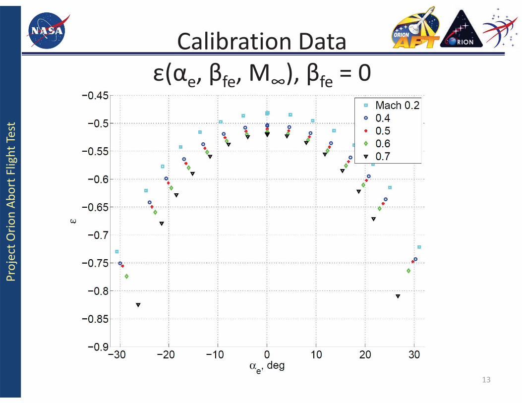
• Database made up entirely of CFD data generated with OVERFLOW; a Navier Stokes flow solver
• The portion of vehicle forward of the AM nozzles was modeled in the CFD
• ACM was not modeled • Mach range
• {0.2, 0.4, 0.5, 0.6, 0.7} • Alpha range
• {0.0, 2.5, 5.0, 7.5, 10, 12.5, 15, 20} • Beta range
– {0.0} • Took advantage of vehicle
axisymmetry to algebraically expand the database
11
Calibration Data
α, d
eg
β, deg

Proj
ect O
rion
Abor
t Flig
ht Te
st
Calibration Data α(αe, βfe, M∞), βfe = 0
12
Proj
ect O
rion
Abor
t Flig
ht Te
st
13
Calibration Data ε(αe, βfe, M∞), βfe = 0

Proj
ect O
rion
Abor
t Flig
ht Te
st
Best Estimated Trajectory: BET
• Used combination of: – Inertial data – radar tracking – optical observations – day of flight atmosphere profile
• To determine data parameters of the vehicle along its trajectory
14

Proj
ect O
rion
Abor
t Flig
ht Te
st
15
Flight Data Comparison: Angle of Attack
2. Abort Motor Burnout
3. Reorientation Started

Proj
ect O
rion
Abor
t Flig
ht Te
st
16
Flight Data Comparison: Sideslip
2. Abort Motor Burnout 3. Reorientation Started

Proj
ect O
rion
Abor
t Flig
ht Te
st
17
Flight Data Comparison: Freestream Static Pressure
2. Abort Motor Burnout
3. Reorientation Started

Proj
ect O
rion
Abor
t Flig
ht Te
st
18
Flight Data Comparison: Impact Pressure
2. Abort Motor Burnout 3. Reorientation Started

Proj
ect O
rion
Abor
t Flig
ht Te
st
19
Flight Data Comparison: Mach Number
2. Abort Motor Burnout 3. Reorientation Started

Proj
ect O
rion
Abor
t Flig
ht Te
st
ACM Jet Interaction With FADS Ports
• 9 Points considered along the flight trajectory prior to reorientation
• 18 CFD cases run using OVERFLOW: a Navier Stokes Flow Solver
• 9 cases ACM on, 9 cases ACM off – Input
• Alpha, Beta from FADS • Mach from BET • Free stream pressure
from Balloon data • Only portion of vehicle forward
of AM nozzles modeled
20
ACM-OFF ACM-ON
DELTA Cp = ACM-ON – ACM-OFF

Proj
ect O
rion
Abor
t Flig
ht Te
st
Effect of Attitude Control Motors on FADS Ports
21
Impact Pressure [psf]
2. Abort Motor Burnout 3. Reorientation Started
ZFADS
YFADS

Proj
ect O
rion
Abor
t Flig
ht Te
st
CFD to Flight Data Comparison: Angle of Attack
22
2. Abort Motor Burnout
3. Reorientation Started

Proj
ect O
rion
Abor
t Flig
ht Te
st
23
CFD to Flight Data Comparison: Sideslip
2. Abort Motor Burnout
3. Reorientation Started
Proj
ect O
rion
Abor
t Flig
ht Te
st
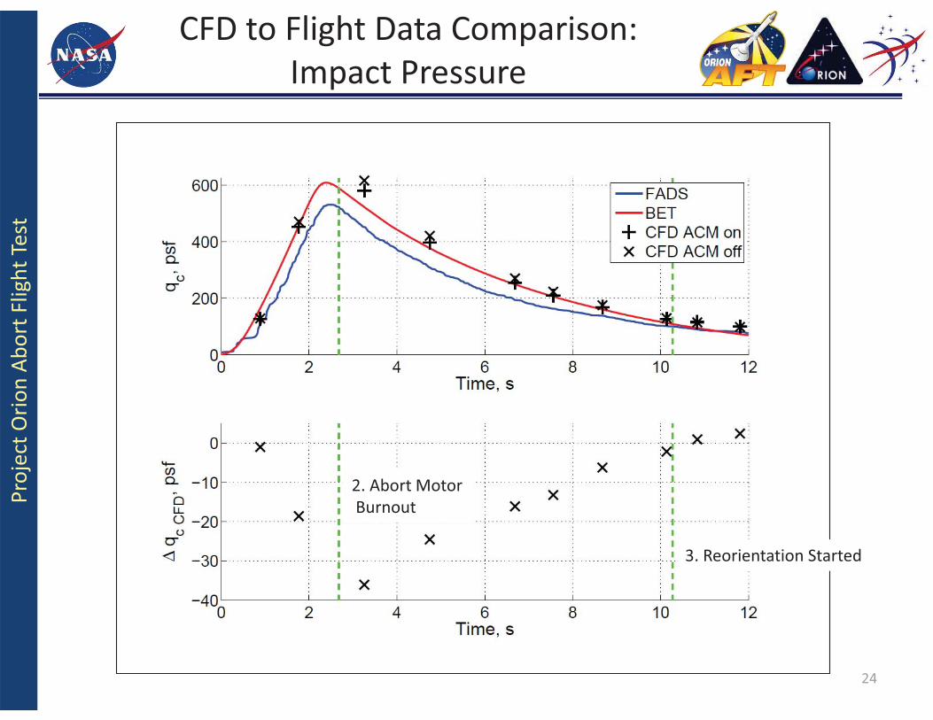
24
CFD to Flight Data Comparison: Impact Pressure
2. Abort Motor Burnout
3. Reorientation Started

Proj
ect O
rion
Abor
t Flig
ht Te
st
25
CFD to Flight Data Comparison: Freestream Static Pressure
2. Abort Motor Burnout
3. Reorientation Started

Proj
ect O
rion
Abor
t Flig
ht Te
st
26
CFD to Flight Data Comparison: Mach Number
2. Abort Motor Burnout
3. Reorientation Started

Proj
ect O
rion
Abor
t Flig
ht Te
st
Summary • PA1 airdata estimates from the FADS system showed influences of the
adjacent firing rocket motor nozzles • CFD study showed less influence of the ACM than expected given the PA1
BET to FADS comparison • New calibration database necessary
– minimum required: CFD which models complete vehicle – desired: combination of Wind tunnel and CFD which incorporate ACM and AM
• New CFD study needed with model of complete vehicle including ACM and AM models
27

Proj
ect O
rion
Abor
t Flig
ht Te
st
PA1 Movie
28
http://www.youtube.com/watch?v=wzIcDDJyTRI (Space City Films)
Proj
ect O
rion
Abor
t Flig
ht Te
st BACK-UP
29

Proj
ect O
rion
Abor
t Flig
ht Te
st
Triples Algorithm • Uses combinations of pressures from three
distinct ports along the axis of interest • Angle of attack(α) – Use pressure readings from ports along Z-axis
• Flank angle(βf) – Use pressure readings from ports along Y-axis
• Side slip(β)
30

Proj
ect O
rion
Abor
t Flig
ht Te
st
Triples Algorithm Angle of Attack
• Let:
31

Proj
ect O
rion
Abor
t Flig
ht Te
st
Triples Algorithm Angle of Attack
• Used ports along the Z axis: φ = 0, π • All combinations of three distinct ports were considered (i, j,
k). • By taking the differences in pressure; qc, P∞ and є are decoupled from equation • With φ = 0, π; sideslip is also removed from the equation • Resulting αe is calibrated to wind tunnel data and/or CFD data
to get α
32