analysis of ato system operation scenarios based on uppaal
TRANSCRIPT
electronics
Article
Analysis of ATO System Operation Scenarios Based onUPPAAL and the Operational Design Domain
Zicong Meng 1 , Tao Tang 2, Guodong Wei 1,* and Lei Yuan 2
�����������������
Citation: Meng, Z.; Tang, T.; Wei, G.;
Yuan, L. Analysis of ATO System
Operation Scenarios Based on
UPPAAL and the Operational Design
Domain. Electronics 2021, 10, 503.
http://doi.org/10.3390/
electronics10040503
Academic Editor: Davide Astolfi
Received: 25 January 2021
Accepted: 18 February 2021
Published: 21 February 2021
Publisher’s Note: MDPI stays neutral
with regard to jurisdictional claims in
published maps and institutional affil-
iations.
Copyright: © 2021 by the authors.
Licensee MDPI, Basel, Switzerland.
This article is an open access article
distributed under the terms and
conditions of the Creative Commons
Attribution (CC BY) license (https://
creativecommons.org/licenses/by/
4.0/).
1 School of Electronic and Information Engineering, Beijing Jiaotong University, Beijing 100044, China;[email protected]
2 The State Key Laboratory of Rail Traffic Control and Safety, Beijing Jiaotong University, Beijing 100044, China;[email protected] (T.T.); [email protected] (L.Y.)
* Correspondence: [email protected]; Tel.:+86-1761-060-9306
Abstract: With the gradual maturity of the automatic train operation (ATO) system in subways,its application scope has also expanded to the high-speed railway field. Considering that theATO system is still in the early stages of operation, it will take time to fully mature, and definitespecifications of the requirements for system operation have not yet been formed. This paper presentsthe operational design domain (ODD) of the high-speed railway ATO system and proposes a scenarioanalysis method based on the operational design domain to obtain the input conditions of thesystem requirements. The article models and verifies the scenario of the linkage control of the doorand platform door based on the UPPAAL tools and extracts the input and expected output of thesystem requirements of the vehicle ATO system. Combined with the input conditions of the systemrequirements, the system requirements of the vehicle ATO in this scenario are finally obtained, whichprovides a reference for future functional specification generation and test case generation.
Keywords: operation design domain; ATO; UPPAAL; timed automata
1. Introduction
At the end of 2019, the Beijing-Zhangjiakou Railway equipped with Chinese self-developed high-speed rail automatic driving system opened, marking the arrival of theera of intelligent high-speed rail. As the demand for intelligent automation in high-speedrailways continues to increase, ATO systems will play an increasingly important role intrain operation control. ATO system research is becoming more and more important due tothe significance of high-speed railways, and related system tests are urgently needed.
The current research on the realization of the ATO function mainly focuses on theATO control algorithm. Liu et al. [1] designed an energy-saving algorithm for the ATOsystem based on the tabu search algorithm. Wang et al. [2] proposed a fast optimiza-tion method that considers both braking accuracy and driving comfort during the oper-ation of the ATO system. Yang et al. [3] designed a hybrid model prediction frameworkbased on model predictive control, which achieved precise control under strict constraints.Kong et al. [4] proposed a non-singular fast terminal sliding mode control strategy basedon self-organizing radial basis function neural network approximation to achieve safe andreliable train operation. Cao et al. [5] discussed the application of fuzzy predictive controlto the ATO system and compared it with the traditional control technology. In the currentATO system research, the research on the ATO control algorithm is to find the optimal traincontrol scheme and the key elements that affect train operation. In addition to the detailedand in-depth design of the system itself, a mature system needs to have detailed tests onthe operation of the system to ensure the safety of the system.
Scenario-based analysis is an important method in ATO system research. Yan et al. [6]used STPA to conduct human error and management-related security risk analysis of the
Electronics 2021, 10, 503. https://doi.org/10.3390/electronics10040503 https://www.mdpi.com/journal/electronics
Electronics 2021, 10, 503 2 of 18
operating scenarios for the ATO system. Zhang et al. [7] took a typical temporary speed-limit server switching scheme as an example, constructed its symbolic verification programmodel, and generated related test cases through mutation testing. One of the key pointsof system testing is to systematically find all possible situations for train operation anddesign test cases for these situations. In order to fully obtain these scenarios, it is necessaryto combine the research of the control strategy of the high-speed railway ATO system toexplore the environment that the system needs to deal with and the design indicators ofthe system. That means that before designing system test cases, various requirements ofthe system, such as functional requirements, non-functional requirements, and systemrequirements, need to be extracted.
Some scholars have carried out relevant research on the extraction of system require-ments. John et al. [8] described and analyzed the requirement development process in ascenario-based design through case studies. They used classroom scenarios to evaluateand design the requirements. Bindschadler et al. [9] described a requirement developmentmethod that is flexible enough to serve various environments and constraints throughNASA’s project management process. Daniel et al. [10] proposed a method to describerequirements formally by replacing natural language with state transition diagrams. Acontrol experiment was carried out using this method to verify its role in disambigua-tion. Yang et al. [11] proposed a method to extract software requirements from existingknowledge sources through natural language processing and evaluated the extracted earlyrequirements in terms of seismology, building products, and computational fluid dynamics.Michel et al. [12] proposed a SysML-based requirements engineering method based onmodel-driven requirements and use case diagrams. Modeling user requirements graph-ically and clearly maps the relationship between requirements and use case diagramsand achieves system decomposition in early system development activities. Reggio [13]introduced the extraction method of IoT system requirements, using UML and extendeddomain models to generate functional requirement specifications.
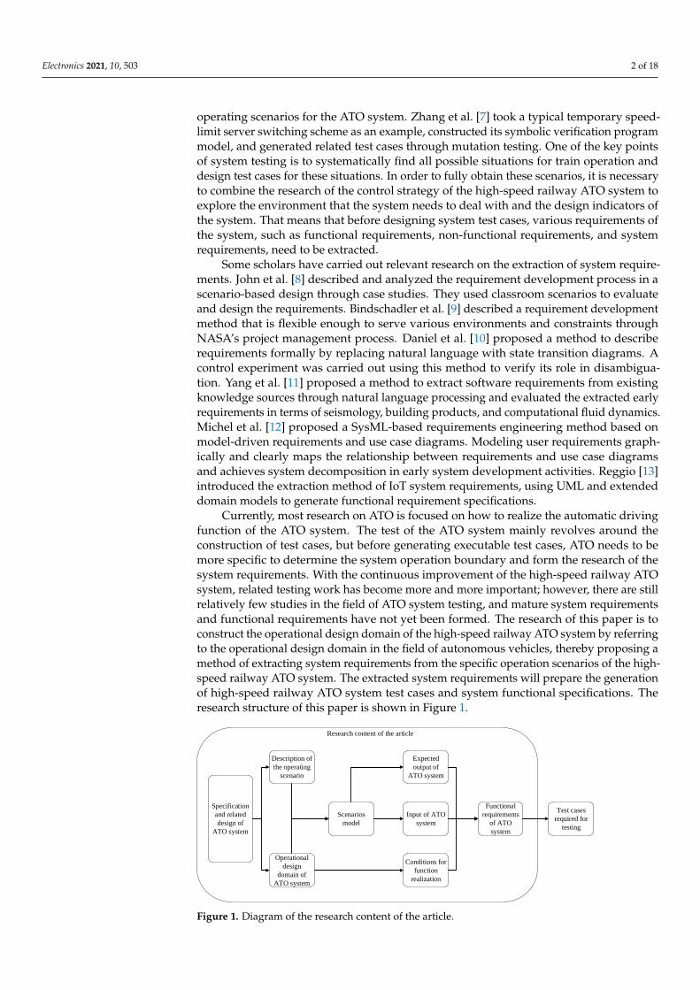
Currently, most research on ATO is focused on how to realize the automatic drivingfunction of the ATO system. The test of the ATO system mainly revolves around theconstruction of test cases, but before generating executable test cases, ATO needs to bemore specific to determine the system operation boundary and form the research of thesystem requirements. With the continuous improvement of the high-speed railway ATOsystem, related testing work has become more and more important; however, there are stillrelatively few studies in the field of ATO system testing, and mature system requirementsand functional requirements have not yet been formed. The research of this paper is toconstruct the operational design domain of the high-speed railway ATO system by referringto the operational design domain in the field of autonomous vehicles, thereby proposing amethod of extracting system requirements from the specific operation scenarios of the high-speed railway ATO system. The extracted system requirements will prepare the generationof high-speed railway ATO system test cases and system functional specifications. Theresearch structure of this paper is shown in Figure 1.
Specification
and related
design of
ATO system
Operational
design
domain of
ATO system
Description of
the operating
scenario
Scenarios
model
Conditions for
function
realization
Input of ATO
system
Expected
output of
ATO system
Test cases
required for
testing
Functional
requirements
of ATO
system
Research content of the article
Figure 1. Diagram of the research content of the article.

Electronics 2021, 10, 503 3 of 18
2. Operational Design Domain of the High-Speed Railway ATO System2.1. Introduction to the Operational Design Domain
SAE (Society of Automotive Engineers) defines the ODD as “The specific conditionsunder which a given driving automation system or feature thereof is designed to function,including, but not limited to, driving modes”. The operational design domain is a setof normal working conditions defined at the design level of the train automatic drivingsystem. Further, the ODD represents the conditions that support the normal operation ofthe automatic driving system and the constraints that determine the normal operation ofthe system. In general, the ODD is useful for the following tasks [14].
1. Design process: Defining the ODD helps identify what scenarios the automateddriving system must handle. System-wide and system requirements can then bedefined alongside the ODD.
2. Testing and verification: The ODD can be sampled to generate test cases with varyinglevels of detail for unit testing or integration testing via simulation.
3. Online monitoring: The ODD can be instantiated as a runtime object to be mea-sured and validated during operation. This is also known as functional boundarymonitoring [15].
Thorn E. et al. [16] gave a classification framework for ODD construction. This ODDclassification adopts the form of a hierarchical structure of categories and subcategories.Each category has a definition and a level where it is appropriate. This classification isdescriptive, not normative, because it is foreseeable that these elements can be organizedinto several different groups. The taxonomy provides a structured method to organizeand identify various ODDs for automated driving system functions. The Figure 2 showsthe ODD classification framework with top-level categories and direct sub-categoriesconstructed in the text.
ODD
Road
Infrastructure
Road TypePavement
MaterialsRoad Width
Geometric
Characteristics
Operational Constraints
Speed LimitTraffic
Conditions
Objects
SignageRoad
Users
Communication
Other
Vehicles
Traffic Management
System
Fleet Management
System Sensors
Environmental
Conditions
Weather Ilumination
Operation
Zones
Management
Zones
Restricted
Zones
Administrative
Zones
Interference
Zones
Traffic Light
Vehicle
Restrictions
Visibility Road Friction
Obstacles
Traffic Rules
Figure 2. The ODD classification framework with top-Level categories and immediate subcategories.
After referring to the contents of the vehicle and system design in the literature [17–22],combined with the concept of the operational design domain of auto-driving technologyin the literature [16], this paper extracts the operational design domain of the high-speedrailway ATO system.

Electronics 2021, 10, 503 4 of 18
2.2. System Operation Characteristics
1. The terrain of China is complicated, and ramps, bends, and tunnels were built ac-cording to the terrain during the construction of the running track. For high-speedrailways, generally, the maximum gradient is not allowed to be greater than 20‰,and the difficult areas are no greater than 30‰. Steel track-carrying trains are used torun mainly ballastless tracks, and the standard gauge is usually 1435 mm.
2. Through the construction of various facilities, many stations have been establishedalong the railway for passengers to get on and off. Some stations are equipped withplatform screen doors. At the same time, turnouts are set to guide trains into differentplatform lanes.
3. The operation of the system has its normal temperature, humidity, wind speed, andother environmental requirements. In extreme weather such as strong winds, severerain, and snow, the operation of the system will be restricted.
4. System operation has a boundary: the maximum speed is limited to 350 km/h; thespeed in the ceiling speed zone is no less than 80 km/h; and the track the train entersat the station is restricted by the operation plan. The system’s information interactionhas a maximum response time. The response time is regarded as a communicationtimeout. The constraints in operation are also the basis for judging the normaloperation of the system.
5. The high-speed railway ATO system is based on the CTCS-2/CTCS-3 level traincontrol system. The train is equipped with an ATO unit to realize automatic drivingcontrol, and a dedicated precision positioning transponder is installed on the groundto achieve special positioning. The ground equipment communicates via GPRS(General Packet Radio Service) to realize platform door control, data transmissionbetween stations, and train operation adjustment plan (referred to as the operationplan) processing.
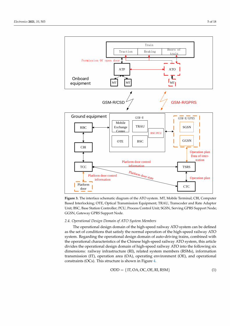
2.3. Structure and Interface of the High-Speed Railway ATO System
The high-speed rail ATO system is based on the CTCS-2/CTCS-3 level train controlsystem, with ATO equipment, GPRS radio, and other related equipment added to the train;the ground equipment is in the temporary speed restriction server (TSRS), centralizedtraffic control (CTC), train control center (TCC), and other equipment. The function isadded to the upper part; the precise positioning transponder is added to the station stockroad. The high-speed rail ATO system mainly includes five items: automatic departurefrom the station, automatic operation of the section, automatic stop at the station, automaticdoor opening, and linkage control of the door and platform door. The high-speed railATO system train equipment includes the newly added ATO and train, the ATO andautomatic train protection system (ATP) interface, the ATP and train interface, the groundequipment added to TCC and platform door system interface, the modified TSRS and TCC,the TSRS and CTC interface, the ATO train equipment, and the ground TSRS equipmentwith the newly added GSM-R/GPRS interface. The high-speed rail ATO system interfacediagram is shown in Figure 3. The classification of the existing operational design domainsaccording to requirement specifications and overall technical specifications is an importantpart of constructing operational design domains. Accurate classification is related to theorganization of the operational design domain and the completeness of the final result, soit is the basis for in-depth research.
Electronics 2021, 10, 503 5 of 18
GSM-R/GPRSGSM-R/CSD
Onboard equipment
Traction BrakingDoors of train
ATP ATO
MT MT MT
RBC
CBI
Platform
door
TCC TSRS
CTC
Ground equipment
Mobile
Exchange
Center
TRAU
BSCOTE
BSC/PCU
GSM-R GSM-R/GPRS
SGSN
GGSN
Train
Permission Of open door
Operation plan
Data of inter-
station
Operation plan
Platform door control
information
Platform door control
information
Figure 3. The interface schematic diagram of the ATO system. MT, Mobile Terminal; CBI, ComputerBased Interlocking; OTE, Optical Transmission Equipment; TRAU, Transcoder and Rate AdaptorUnit; BSC, Base Station Controller; PCU, Process Control Unit; SGSN, Serving GPRS Support Node;GGSN, Gateway GPRS Support Node.
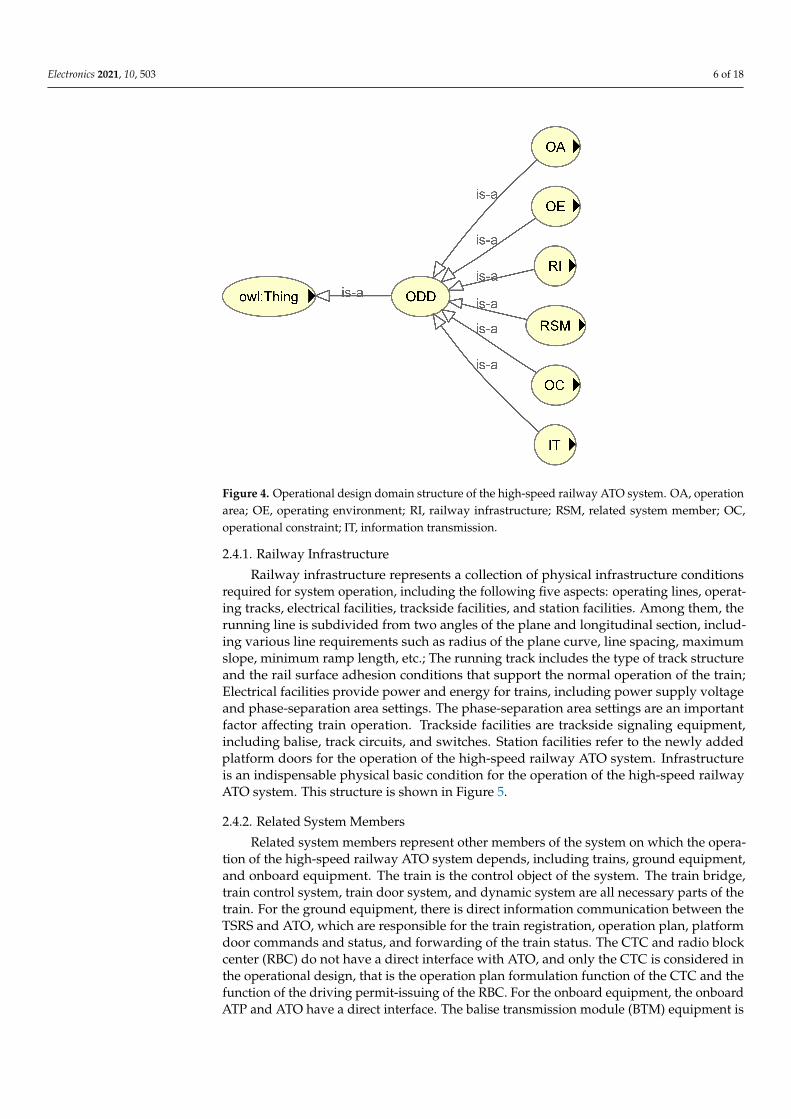
2.4. Operational Design Domain of ATO System Members
The operational design domain of the high-speed railway ATO system can be definedas the set of conditions that satisfy the normal operation of the high-speed railway ATOsystem. Regarding the operational design domain of auto-driving trains, combined withthe operational characteristics of the Chinese high-speed railway ATO system, this articledivides the operational design domain of high-speed railway ATO into the following sixdimensions: railway infrastructure (RI), related system members (RSMs), informationtransmission (IT), operation area (OA), operating environment (OE), and operationalconstraints (OCs). This structure is shown in Figure 4.
ODD = { IT, OA, OC, OE, RI, RSM} (1)
Electronics 2021, 10, 503 6 of 18
Figure 4. Operational design domain structure of the high-speed railway ATO system. OA, operationarea; OE, operating environment; RI, railway infrastructure; RSM, related system member; OC,operational constraint; IT, information transmission.
2.4.1. Railway Infrastructure
Railway infrastructure represents a collection of physical infrastructure conditionsrequired for system operation, including the following five aspects: operating lines, operat-ing tracks, electrical facilities, trackside facilities, and station facilities. Among them, therunning line is subdivided from two angles of the plane and longitudinal section, includ-ing various line requirements such as radius of the plane curve, line spacing, maximumslope, minimum ramp length, etc.; The running track includes the type of track structureand the rail surface adhesion conditions that support the normal operation of the train;Electrical facilities provide power and energy for trains, including power supply voltageand phase-separation area settings. The phase-separation area settings are an importantfactor affecting train operation. Trackside facilities are trackside signaling equipment,including balise, track circuits, and switches. Station facilities refer to the newly addedplatform doors for the operation of the high-speed railway ATO system. Infrastructureis an indispensable physical basic condition for the operation of the high-speed railwayATO system. This structure is shown in Figure 5.
2.4.2. Related System Members
Related system members represent other members of the system on which the opera-tion of the high-speed railway ATO system depends, including trains, ground equipment,and onboard equipment. The train is the control object of the system. The train bridge,train control system, train door system, and dynamic system are all necessary parts of thetrain. For the ground equipment, there is direct information communication between theTSRS and ATO, which are responsible for the train registration, operation plan, platformdoor commands and status, and forwarding of the train status. The CTC and radio blockcenter (RBC) do not have a direct interface with ATO, and only the CTC is considered inthe operational design, that is the operation plan formulation function of the CTC and thefunction of the driving permit-issuing of the RBC. For the onboard equipment, the onboardATP and ATO have a direct interface. The balise transmission module (BTM) equipment is

Electronics 2021, 10, 503 7 of 18
related to the reception of the transponder information, and the track circuit reader (TCR)equipment affects the control commands of the ATP. This structure is shown in Figure 6.
Figure 5. Structure diagram of Railway Infrastructure.
Figure 6. Structure diagram of related system members.

Electronics 2021, 10, 503 8 of 18
2.4.3. Information Transmission
Information transmission represents the relationship between the information in-terface in the operation of the system and the information transmitted on the channel,including train-ground communication, train inside communication, and the ground insidecommunication. Referring to the ATO system interface diagram in the previous section,the train-to-ground communication includes the communication channels among the RBC,ATP, TSRS, and ATO. The train inside communication includes the interface between ATOand the train, the interface between ATP and the train, the interface between ATP and ATO,and the interface among the BTM, TCR, and ATP. The ground inside communication onlyrefers to the information channel related to ATO, the communication interface betweenthe CTC and TSRS, the adjacent TSRS, and the TSRS and TCC. Data in the informationtransmitted have been described in the foregoing passages and will not be repeated here.This structure is shown in Figure 7.
Figure 7. Structure diagram of information transmission.
2.4.4. Operating Area
The operating area refers to the division of the system operation in space, includingintra-station area and between-station area. There are many ways to divide the operatingspace. Here, the area within the station and the area between the stations are dividedaccording to the impact on the operation of the ATO system: in addition to the traditionalsideline and the mainline, the station has added switch sections that require a speed limit.The between-station area is divided into phase areas and non-phase areas according to thelayout of the electrical facilities. This structure is shown in Figure 8.

Electronics 2021, 10, 503 9 of 18
Figure 8. Structure diagram of the operating area.
2.4.5. Operational Constraints
The operational constraints refer to the set of constraints that define the normaloperation of the system, including time constraints, control constraints, and distanceconstraints. Time constraints include communication time and the normal delay of systemcontrol; control constraints include hard ATP control commands and flexible operationplan constraints; distance constraints represent distance conditions that define whether thesystem is operating normally or not, including but not limited to precise stopping criteriaand safe stopping distance. This structure is shown in Figure 9.
Figure 9. Structure diagram of the operational constraints.
2.4.6. Operating Environment
The operating environment refers to the natural environmental constraints of the sys-tem operation, including weather, temperature, and humidity, that is wind, rain, snow, andthe accompanying natural environment such as temperature, humidity, and wind speed.This structure is shown in Figure 10.

Electronics 2021, 10, 503 10 of 18
Figure 10. Structure diagram of the operating environment.
3. Timed Automata and the UPPAAL Tool3.1. Introduction to Timed Automata
Timed automata (TA) is an abstract model designed to capture the time behavior ofreal-time systems [23]. It is essentially a finite state machine with extended real-valuedclock variables. When the system starts, these clocks increase monotonically at the samerate and measure the elapsed time to control the triggering of events. A timed automata isa tuple (Q, q, E, X, I, T, Y) where:
1. Q means a limited set of positions; q ∈ Q is the initial position.2. E means a limited set of observable behaviors.3. X represents a limited set of clock variables.4. I means the mapping from position to position invariant.5. T means a finite set of integer variables.6. Y means a set of transitions.
The scenario of the linkage control of the door and platform door mainly involvesthe four modules of onboard ATP, TSRS, train, and onboard ATO. Therefore, the mod-eling object selects these four modules, and we denote them as TAATO, TAATP, TATrain,and TATSRS.
3.2. Introduction to the Verification Tool UPPAAL
UPPAAL is a modeling and verification tool specifically for real-time systems. WithTA as the modeling language, it provides an efficient, easy-to-use, and portable system.UPPAAL uses a graphical user interface. UPPAAL is mainly composed of the editor,simulator, and validator. The editor can describe the system behavior as a TA network withclock and data variables. The simulator can be used to check the information interactionbetween the models after the model design is completed, thereby helping the model tocorrect errors. The verifier can study the state space of the system according to the symbolstate represented by the constraint, so as to realize the verification of immutability andreachability. The UPPAAL verification model is based on the BNF (Backus Normal Form)grammar [24], and the meaning of each expression is shown in Table 1.

Electronics 2021, 10, 503 11 of 18
Table 1. The grammatical meaning of BNF.
Statement Meaning
E[]P There is an execution path; all states satisfy PE <> P There is an execution path such that a certain state satisfies P
A[]P For all execution paths, all states satisfy PA <> P For all execution paths, there are states satisfying PP → Q If P is satisfied, then Q must be satisfied
4. Case Study4.1. Scenario Description and Analysis
After ATP confirms that the train is stopped, it sends the onboard ATO permissionto open the door. According to the pre-selected door control mode, if it is in AO/MC(automatic opening and manual closing doors) mode, the onboard ATO will operate thedoor. If it is in MO/MC (manual opening and manual closing doors) mode, the driverwill open the door manually. After the onboard ATO sends the door open command orreceives the state of the door button pressed, it needs to send the door open command of theplatform door. The platform door open command is sent by ATO to the TSRS in the groundequipment that governs the train. Based on the train’s marshalling information and thecorresponding ground platform door settings, the TSRS confirms that the correspondingtrain is properly stopped and then sends a door opening command to the correspondingtrain control center. After the platform door system opens the platform door, the TSRSinforms ATO of the platform door status, and the train ATO displays on the DMI (DriverMachine Interface) whether the platform door linkage is successful. If the status of theplatform door is not received for a certain period of time, it will be regarded as a failure.Using the operational design domain of the high-speed railway ATO system as a tool, thescenario was re-deconstructed, and the Table 2 was designed to reflect the mapping of thelinkage control scenario of train doors and platform doors in the operational design domain.
Table 2. ODD members of the linkage control scenario.
ODD Type ODD Class ODD Members Details
RSM
Ground equipmentTSRS Forwarding platform door
control and status information
TCC Control platform door
Onboardequipment ATP
Outputting door openingpermission and processing DMI
display information
Running train
Train doors Controlled object
Train dynamic system stopping
Train control system AM(Automatic Driving Mode)
IT
Train inside
ATP-ATO Open train doors permission andinformation for display
ATO-trainDoor open command, the state
of the door button, doorcontrol mode
Ground inside
CTC-TSRS Operation plan
TSRS-TCC Platform door control commandand platform door state
Train ground TSRS-ATOPlatform door control command,
platform door state, andoperation plan
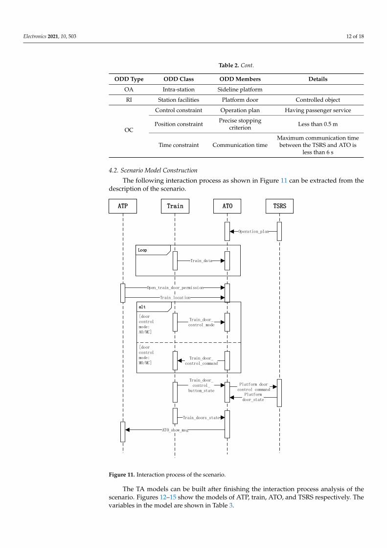
Electronics 2021, 10, 503 12 of 18
Table 2. Cont.
ODD Type ODD Class ODD Members Details
OA Intra-station Sideline platform
RI Station facilities Platform door Controlled object
OC
Control constraint Operation plan Having passenger service
Position constraint Precise stoppingcriterion Less than 0.5 m
Time constraint Communication timeMaximum communication timebetween the TSRS and ATO is
less than 6 s
4.2. Scenario Model Construction
The following interaction process as shown in Figure 11 can be extracted from thedescription of the scenario.
ATP Train ATO TSRS
Open_train_door_permission
Train_door_control_mode
Train_door_control_command
Train_door_control_
buttom_state
alt
[doorcontrol mode:MO/MC]
[doorcontrol mode:AO/MC]
Platform door control command
Platform door_state
ATO_show_msg
Operation_plan
Loop
Train_data
Train_location
Train_doors_state
Figure 11. Interaction process of the scenario.
The TA models can be built after finishing the interaction process analysis of thescenario. Figures 12–15 show the models of ATP, train, ATO, and TSRS respectively. Thevariables in the model are shown in Table 3.

Electronics 2021, 10, 503 13 of 18
Figure 12. The ATP model of the linkage control scenario of train doors and platform doors.
Figure 13. The train model of the linkage control scenario of train doors and platform doors.
Figure 14. The ATO model of the linkage control scenario of train doors and platform doors.

Electronics 2021, 10, 503 14 of 18
Figure 15. The TSRS model of the linkage control scenario of train doors and platform doors.
Table 3. Variables in the TA model.
Variable Name Type Meaning
plat f orm_cmd boolean The signal for open the platform doors permission.
PS integer The signal for handling passenger transport service(1: handle; 0: does not handle).
stop integer The signal for the train stops accurately(1: accurately; 0: inaccurately).
double_perm integer The signal for open both side train doors permission(1: both side; 0: one side).
send_message integer The signal for send display information(1: opening linkage results; 2: closing linkage results).
door_mode integer The signal for train doors control mode (1: MO/MC; 2: AO/MC).door_state integer The signal for train doors status (1: opened; 2: closed).
end integer The signal for interactive termination (0: does not end; 1: end).T_trans clock The clock for train door control time.
T_control clock The clock for platform message transmission time.T_delate clock The clock for communication delay.
4.3. Verification of the Scenario
After completing the construction of the model, the model needs to be verified toconfirm whether the model is consistent with the scenario design. If the verification fails,the model should be positioned and analyzed according to the prompt results, and themodel should be continuously corrected and modified to finally realize the model, and theconsistency of the description ensures the credibility of subsequent demand extraction. Inaccordance with the previous description of the model verification technology, this articleuses the UPPAAL tools to carry out model verification from two perspectives of dynamicexecution verification and property verification.
4.3.1. Performing Verification Dynamically
In the scenario of the linkage control of the train door and platform door, the infor-mation interaction relationship among ATO, ATP, the train, and the TSRS is shown inFigure 16.
Taking the UML sequence diagram as a reference, the migration is performed step bystep in the UPPAAL simulator to observe the execution path of the model and analyze theinteractive behavior of the model. If a migration cannot be executed, an error message willappear in the simulator to assist in the modification of the model. Then, the verificationprocess of the model interaction process is given in Figure 17.

Electronics 2021, 10, 503 15 of 18
ATO
-send ATO_show_msg
-send Train_door_control_command
-send Platform_door_control_command
-recive Platform_door_state
-recive Open_train_door_permission
-recive Train_door_control_mode
-recive Train_door_control_buttom_state
-recive Operation_plan
Train
-send Train_door_control_mode
-send Train_door_control_buttom_state
-recive Train_door_control_command
ATP
-send Open_train_door_permission
-recive ATO_show_msg
TSRS
-send Platform_door_state
-send Operation_plan
-recive Platform_door_control_command
Figure 16. The information interaction relation in the linkage control scenario of train doors andplatform doors.
Figure 17. The verification diagram of the interaction process.

Electronics 2021, 10, 503 16 of 18
4.3.2. Property Verification
Property verification is done to check whether the built model meets the logic functioncharacteristics and timing function characteristics required in the specification through thereachability of the model. The functional attributes are summarized and extracted andconverted into corresponding BNF sentences for verification in the UPPAAL validator. TheTable 4 gives the function points of the verification and verification statements and results.
Table 4. TA model validation results.
Properties BNF Statement Result Calculating Time
Can restart platformdoor linkage
E[](ATO.showcloselink_ f ailed impliesATO.send_Plat f orm_door_open_cmd) pass 2.8 ms
Automatic dooropening
E<>(ATO.idle impliesATO.ATO_control_door) pass 1.5 ms
Send platform doorcontrol command
E<>(ATO.idle impliesTSRS.rec_plat f orm_door_cmd) pass 1.6 ms
Send linkage results E<>(ATO.idle impliesATP.rec_ATO_show_msg) pass 1.9 ms
Informationinteraction time is
less than 6 s
A[](ATO.send_Plat f orm_door_open_cmdimplies T_delate<=6) and
(ATO.rec_Plat f orm_door_open_stateimplies T_delate<=6) and
(ATO.send_close_door_cmd impliesT_delate<=6) and
(ATO.rec_Plat f orm_door_close_stateimply T_delate<=6)
pass 3.8 ms
Total time 11.6 ms
4.4. Demand Extraction
Using the verified scenario model as the demand model, combined with the oddmapping of the scenario, we extract the design input and expected output in the scenarioas Table 5.
Table 5. System requirement parameters in the scenarios.
Conditions Input Output
1. AM mode 1. Operation plan 1. Doors open command2. Passenger service 2. Open train doors permission 2. Platform door control command3. Sideline platform 3. The state of the door button 3. Information for display
4. Stop 4. Doors control mode5. Platform door state
The following system requirements can be extracted:
1. In the door control mode AO/MO, the onboard ATO can automatically open the dooraccording to the plan when the sideline platform has the condition of stopping.
2. In the AM mode, the onboard ATO can send correct platform door control commandsto the TSRS based on the planning and marshalling information and the status of thedoor buttons.
5. Conclusions and Future Work
This paper constructs the operational design domain of the high-speed railway ATOsystem with reference to the framework of the operational design domain of autopilot andanalyzes the linkage control scenarios of train doors and platform doors. The article usesTA grammar and UPPAAL tools to build a model of the scenario and verify it and finally
Electronics 2021, 10, 503 17 of 18
extracts the system requirements of the onboard ATO in the scenario. The extracted systemrequirements will provide support for future test case design. The next research will focuson further improving the extraction results of the system requirements. Further study willbe done of the effective method for generating test cases based on system requirements tomeet the requirements of laboratory system testing.
Author Contributions: Conceptualization, Z.M. and T.T.; methodology, Z.M.; software, Z.M.; val-idation, Z.M.; formal analysis, Z.M.; resources, T.T.; data curation, Z.M.; writing—original draftpreparation, Z.M.; writing—review and editing, G.W. and L.Y.; visualization, Z.M.; supervision, G.W.;project administration, G.W.; funding acquisition, L.Y. All authors read and agreed to the publishedversion of the manuscript.
Funding: This work was supported by the key project of the national science technology researchand development program of the National Railway Group: “Research on the key technologies ofintegrated simulation and test environment evaluation for high-speed railway automatic drivingsystem” (W19D00071) and by the National Engineering Research Center for Rail TransportationOperation Control System.
Acknowledgments: The authors would like to thank the State Key Laboratory of rail transit controland safety and the National Engineering Research Center for Rail Transportation Operation ControlSystem for their continuous support of this study.
Conflicts of Interest: The authors declare no conflict of interest.
AbbreviationsThe following abbreviations are used in this manuscript:
ODD Operational design domainATO Automatic train operationCTCS Chinese train control systemGPRS General packet radio serviceTSRS Temporary speed restriction serverCTC Centralized traffic controlTCC Train control centerATP Automatic train protectionRBC Radio block centerBTM Balise transmission moduleTCR Track circuit readerMT Mobile terminalCBI Computer based interlockingOTE Optical transmission equipmentTRAU Transcoder and rate adaptor unitBSC Base station controllerPCU Process control unitSGSN Serving GPRS support nodeGGSN Gateway GPRS support node.TA Timed automataBNF Backus Normal FormSAE Society of Automotive EngineersAO Automatic opening doorsMC Manual closing doorsMO manual opening doorsAM Automatic driving modeDMI Driver machine interface

Electronics 2021, 10, 503 18 of 18
References1. Liu, S.; Cao, F.; Xun, J.; Wang, Y. Energy-Efficient Operation of Single Train Based on the Control Strategy of ATO. In Proceedings
of the 2015 18th International Conference on Intelligent Transportation Systems (ITSC), Gran Canaria, Spain, 15–18 September2015; pp. 2580–2586. [CrossRef]
2. Wang, L.; Xia, L.; Ye, H.; Jiang, M.; Wang, J.; Wang, Y. A Fast Optimization Method for Automatic Train Stop Control. InProceedings of the 2019 15th International Conference on Control and Automation(ICCA), Edinburgh, UK, 16–19 July 2019;pp. 1405–1410. [CrossRef]
3. Yang, Y.; Xu, Z.; Liu, W.; Li,H.; Zhang, R.; Huang, Z. Optimal Operation of High-Speed Trains Using Hybrid Model PredictiveControl. J. Adv. Transp. 2018, 16, 1–16. [CrossRef]
4. Kong, X.; Zhang, T. Non-Singular Fast Terminal Sliding Mode Control of High-Speed Train Network System Based on ImprovedParticle Swarm Optimization Algorithm. Symmetry 2020, 12, 205. [CrossRef]
5. Cao, Y.; Ma, L.; Zhang, Y. Application of fuzzy predictive control technology in automatic train operation. Clust. Comput. 2018, 22,14135–14144. [CrossRef]
6. Yan, F.; Tang, T.; Yan, H. Scenario based STPA analysis in Automated Urban Guided Transport system. In Proceedings of the 2016IEEE International Conference on Intelligent Rail Transportation (ICIRT), Birmingham, UK, 23–25 August 2016; pp. 425–431.[CrossRef]
7. Zhang, Z.; Li, K.; Yuan, L.; Yu, G. Mutation Model-Based Test Case Generation of Chinese Train Control System with AutomaticTrain Operation Function. In Proceedings of the 2018 IEEE International Conference on Intelligent Rail Transportation (ICIRT),Singapore, 12–14 December 2018; pp. 1–5. [CrossRef]
8. John, M.C.; Mary, B.R.; George, C.J.; Jürgen, K. Requirements Development in Scenario-Based Design. Trans. Software Eng. 1998,24, 1156–1170. [CrossRef]
9. Bindschadler, D.; Boyles, C. A Scenario-Based Process for Requirements Development: Application to Mission OperationsSystems. In Proceedings of the 2008 SpaceOps Conference, Heidelberg, Germany, 12–16 May 2008; p. 3516.
10. Daniel, A.; Gursimran, S.W.; Hyunsook, D.;Seok-Won, L. Model-based requirements verification method: Conclusions from twocontrolled experiments. Inf. Softw. Technol. 2014,56, 321–334. [CrossRef]
11. Yang, L.; Emitza G.; Konstantina, T.; Florian, S.; Bernd, B. Automated Requirements Extraction for Scientific Software. InProceedings of the 2015 International Conference on Computational Science(ICCS), Reykjavik, Iceland, 1–3 June 2015; pp. 582–591.[CrossRef]
12. Michel, D.S.S.; Jos, L.M.V. Model-Driven User Requirements Specification using SysML. J. Softw. 2008, 3, 57–68. [CrossRef]13. Reggio, G. A UML-Based Proposalfor IoT System Requirements Specification. In Proceedings of the 10th International Workshop
on Modelling in Software Engineering (MiSE), Gothenburg, Sweden, 22–30 May 2018; pp. 9–16. [CrossRef]14. Ian, C.; Buu, P.; Shahwar, S.; Rick, S.; Krzysztof, C. An Automated Vehicle Safety Concept Based on Runtime Restriction of the
Operational Design Domain. In Proceedings of the 2018 IEEE Intelligent Vehicles Symposium (IV), Suzhou, China, 26–30 June2018; pp. 1910–1917. [CrossRef]
15. Markus, H.; Karl-Heinz, S. Strategy and architecture of a safety concept for fully automatic and autonomous driving assistancesystems. In Proceedings of the 2010 IEEE Intelligent Vehicles Symposium (IV), La Jolla, CA, USA, 21–24 June 2010; pp. 955–960.[CrossRef]
16. Thorn, E.; Kimmel, S.C.; Chaka, M.; Hamilton, B.A. A Framework for Automated Driving System Testable Cases and Scenarios.Available online: https://rosap.ntl.bts.gov/view/dot/38824 (accessed on 1 September 2018).
17. Abramov, I.V.; Nikitin, Y.R.; Abramov, A.I.; Sosnovich, E.V.; Božek, P. Control and diagnostic model of brushless DC motor. J.Electr. Eng. 2014, 65, 277–282. [CrossRef]
18. Božek, P.; Turygin, Y. Measurement of the Operating Parameters and Numerical Analysis of the Mechanical Subsystem. Meas. Sci.Rev. 2014, 14, 198–203. [CrossRef]
19. Blatnický, M.; Sága, M.; Dižo, J.; Bruna, M. Application of Light Metal Alloy EN AW 6063 to Vehicle Frame Construction with anInnovated Steering Mechanism. Materials 2020, 13, 817. [CrossRef] [PubMed]
20. Sága, M.; Blatnický, M.; Vaško, M.; Dižo, J.; Kopas, P.; Gerlici, J. Experimental Determination of the Manson-Coffin Curves for anOriginal Unconventional Vehicle Frame. Materials 2020, 13, 4675. [CrossRef] [PubMed]
21. Fan, L.X.; Cai, M.Y.; Lin, Y.; Zhang, W.J. Axiomatic design theory: Further notes and its guideline to applications. Int. J. Mater.Prod. Technol. 2015, 51, 359–374. [CrossRef]
22. Zhang, W.J.; van Luttervelt, C.A. Toward a resilient manufacturing system. CIRP Ann. 2011, 60, 469–472. [CrossRef]23. Rajeev, A.; David, L.D. A theory of timed automata. Theor. Comput. Sci. 1994, 126, 183–235. [CrossRef]24. Li, S.; Balaguer, S.; David, A.; Larsen, K.G.; Nielsen, B.; Pusinskas, S. Scenario-based verification of real-time systems using
Uppaal. Form. Methods Syst. Des. 2010, 37, 200–264. [CrossRef]