analysis of floorball sticks using high speed camera...
TRANSCRIPT

Analysis of floorball sticks using high speed camera and Abaqus
An explicit simulation of the dynamic behaviour during a slapshot
Master’s Thesis in the International Master’s programme Applied Mechanics
JONNY KARLSSON Department of Applied Mechanics Division of Material and Computational Mechanics
CHALMERS UNIVERSITY OF TECHNOLOGY Göteborg, Sweden 2011 Master’s Thesis 2011:01


MASTER’S THESIS 2011:01
Analysis of floorball sticks using high speed camera and Abaqus
An explicit simulation of the dynamic behaviour during a slapshot
Master’s Thesis in the International Master’s programme Applied Mechanics
JONNY KARLSSON
Department of Applied Mechanics Division of Material and Computational Mechanics
CHALMERS UNIVERSITY OF TECHNOLOGY
Göteborg, Sweden 2011
Analysis of floorball sticks using high speed camera and Abaqus
An explicit simulation of the dynamic behaviour during a slapshot Master’s Thesis in the International Master’s programme Applied Mechanics
JONNY KARLSSON
© JONNY KARLSSON, 2011
Master’s Thesis 2011:01
ISSN 1652-8557
Department of Applied Mechanics
Division of Material and Computational Mechanics
Chalmers University of Technology
SE-412 96 Göteborg
Sweden
Telephone: + 46 (0)31-772 1000
Cover: A snapshot of a recorded slapshot with the model of the stick from the lower hand and down to the blade.
Chalmers Reproservice Göteborg, Sweden 2011
I
Analysis of floorball sticks using high speed camera and Abaqus
An explicit simulation of the dynamic behaviour during a slapshot Master’s Thesis in the International Master’s programme Applied Mechanics
JONNY KARLSSON Department of Applied Mechanics Division of Material and Computational Mechanics
Chalmers University of Technology
ABSTRACT
Floorball took its current form during the end of the 1970’s, and the number of players has been growing rapidly since 1990. As a relatively new sport and industry, manufacturers of floorball sticks have not previously used finite element analysis tools for developing new sticks and pushing the technology forward. In this thesis work high speed camera equipment together with the finite element software Abaqus/CAE was used in order to analyze the dynamic behaviour of a floorball stick. This was performed for a series of slapshots and a finite element model of a floorball stick was created. The recorded material was analyzed frame by frame, which was used as input in an explicit analysis in Abaqus. The input consisted of the position of the lower hand relative to the floor as well as the angle of the stick relative to the floor. The motion during a slapshot was determined in a finite element environment and thus an inverse problem occurred since the deflection was known and the force causing the deflection unknown. During the analysis the contact force between the floor and the stick was determined to 700 N. The method itself, comparison between high speed camera and Abaqus, gave an interesting perspective in the sense that it presented the possibility for direct feedback between the actual stick and the model in Abaqus. This direct feedback relation makes the method interesting for several kinds of implementation.
Key words: floorball, stick, Abaqus, slapshot, high speed camera, inverse identification
II
Analys av innebandyklubbor med hjälp av höghastighetskamera och Abaqus
En explicit simulering av det dynamiska beteendet under ett slagskott
Examensarbete inom Internationella Mastersprogrammet för Tillämpad Mekanik
JONNY KARLSSON
Institutionen för Tillämpad mekanik
Avdelningen för Material- och beräkningsmekanik
Chalmers tekniska högskola
SAMMANFATTNING
Innebandy tog sin nuvarande form i slutet på 1970-talet, och antalet spelare har växt snabbt sedan 1990. Då det är en relativ ny sport och industri, har tillverkarna av innebandyklubbor tidigare inte använt sig av finit element analys i utvecklandet av nya klubbor och därmed fört teknologin ytterligare framåt. Med hjälp av en höghastighetskamera och finit element-programmet Abaqus var det möjligt att skapa en modell av en klubba och analysera det dynamiska beteendet under ett slagskott. Det inspelade materialet analyserades bild för bild, och användes som indata i en explicit analys gjord i Abaqus. Indatan bestod av den nedre handens position relativt golvet samt vinkeln på skaftet. Genom detta kunde rörelsen under ett slagskott bestämmas i en finit element-miljö och ett inverst problem uppstod då nedböjningen var känd medan kraften som orsakade den var okänd. Under analysen kunde kontaktkraften mellan golvet och skaften bestämmas till 700 N. Själva metoden, jämförelsen mellan höghastighestskamera och Abaqus, gav ett intressant perspektiv då det gav möjligheten till en direkt återkoppling mellan klubban i verkligheten och modellen i Abaqus. Den direkta återkopplingen gör att metoden är intressant för många andra tillämpningar.
Nyckelord: innebandy, klubba, Abaqus, slagskott, höghastighetskamera, inversidentifiering
CHALMERS, Applied Mechanics, Master’s Thesis 2011:01 III
Contents
ABSTRACT I
SAMMANFATTNING II
CONTENTS III
PREFACE V
NOTATIONS VI
1 BACKGROUND 1
2 METHOD 2
2.1 Standard test of a floorball stick 2
2.2 Recording a slapshot 2
2.2.1 Sticks and players 3
2.2.2 High-speed camera 3
2.3 Image analysis 4
2.4 Modelling of standard test 6
2.5 Modelling of a slapshot 7
2.5.1 Multi-point constraint 7
2.5.2 Inverse identification 9
3 RESULTS 11
3.1 Material properties 11
3.2 Dynamic behaviour 11
3.3 Contact forces 13
4 DISCUSSION 14
5 CONCLUSION 16
6 REFERENCES 17

CHALMERS, Applied Mechanics, Master’s Thesis 2011:01 IV
CHALMERS, Applied Mechanics, Master’s Thesis 2011:01 V
Preface
In this Master’s Thesis, recordings with high speed camera and simulations in Abaqus have been done as a final step in my education at Chalmers University of Technology. These tests were carried out from March to June 2010 at the facilities of Renew Group AB in Mölnlycke.
I would like to thank everybody at Renew Group AB for the help and support throughout the entire process. I would also like to thank Martin Fagerström for taking the time to help me as well as my examiner Ragnar Larsson for the approval to let me perform this study and the good advices along the road. Finally, I would like to thank 3DS for the kindness of giving me a temporary student license and thus giving me the opportunity to be located at Renew Group AB.
Göteborg, 2011
Jonny Karlsson

CHALMERS, Applied Mechanics, Master’s Thesis 2011:01 VI
Notations
α Angle between the stick and the floor
X Horizontal position of the hand
Y Vertical position of the hand

CHALMERS, Applied Mechanics, Master’s Thesis 2011:01 1
1 Background
Floorball is a relatively new sport that took its current form during the 1980’s. The number of players started to grow substantially in the end of that decade, from less than 1000 to the more then 120 000 that are licensed in Sweden today [1].Throughout the world, the number is soon to be 300 000 [2]. It should be noted that this is without the large amount of players that only plays with friends or associates. Because of this the market for floorball sticks is also growing which makes it important to have a position at the front of the development for the manufacturers.
One possible way to do this is to advise other methods or technologies, where computational simulations can be one of them. Within the industry of e.g. tennis and golf equipment, where the resources are substantially larger, simulation tools have been used for several years. Using simulations, the forces acting on a stick can be determined which gives a better understanding of what demands one must have on a stick. This leads to the possibility to design a stick with better functionality and thereby push the development forward.
These lines are the foundation and the reason for this Master’s Thesis.
CHALMERS, Applied Mechanics, Master’s Thesis 2011:01 2
2 Method
The key-assets in developing a new floorball stick has always been trial and error, complemented with knowledge of previous attempts. In this thesis, a high speed camera and image analysis was used to create the input variables for the finite element model.
2.1 Standard test of a floorball stick
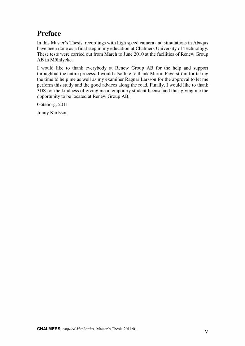
In order to get the approval for league play, every stick needs to have certain properties. These are regulated by the International Floorball Federation, and consist of several tests. One of them is performed by resting a stick on two supports, 800 mm apart, and press with 300 N as seen in Figure 1 below.
Figure 1: The stick rests on two supports 800 mm apart and a force of 300 N is exerted in the middle of the
stick.
The measured maximum deflection must be larger than 23 mm. The test is performed at Renew group with an equipment that is identical with the one used for the certification by SP Technical Research Institute of Sweden [3]. The result will be used later on to compare with the finite element model of the stick.
2.2 Recording a slapshot
The objective was to find where the maximum deflection is during a slapshot, measure how large it is, and by using inverse identification find the forces acting on the stick. Therefore the motion of the stick during a slapshot was needed for the simulation to represent a slapshot.
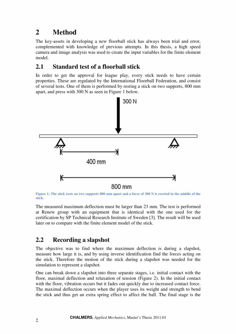
One can break down a slapshot into three separate stages, i.e. initial contact with the floor, maximal deflection and relaxation of tension (Figure 2). In the initial contact with the floor, vibration occurs but it fades out quickly due to increased contact force. The maximal deflection occurs when the player uses its weight and strength to bend the stick and thus get an extra spring effect to affect the ball. The final stage is the
CHALMERS, Applied Mechanics
relaxation of tension which means that the contact between the stick and the floor islost and the stick goes back to
Figure 2: The three different stages that
deflection and relaxation of tension.
2.2.1 Sticks and players
For the recording to be valid several sticks and players were used. 11 male and 2 female players of different skill levels used 12 different sticks. The main difference between the sticks was whether the sticka different approach towards the ball.
2.2.2 High-speed camera
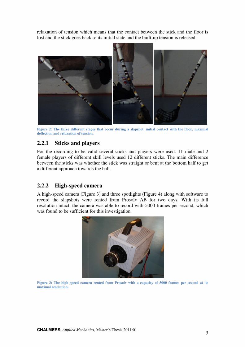
A high-speed camera (Figure record the slapshots were rented from Presolution intact, the camera was able to record with 5000 frames per second, which was found to be sufficient
Figure 3: The high speed camera rented from Prosolv with a capacity of 5000 frames per second at its
maximal resolution.
Applied Mechanics, Master’s Thesis 2011:01
relaxation of tension which means that the contact between the stick and the floor islost and the stick goes back to its initial state and the built-up tension is released
: The three different stages that occur during a slapshot, initial contact with the floor, maximal
deflection and relaxation of tension.
Sticks and players
For the recording to be valid several sticks and players were used. 11 male and 2 female players of different skill levels used 12 different sticks. The main difference
whether the stick was straight or bent at the bottom half to geta different approach towards the ball.
speed camera
Figure 3) and three spotlights (Figure 4) along with software to record the slapshots were rented from Prosolv AB for two days. With its full resolution intact, the camera was able to record with 5000 frames per second, which
for this investigation.
: The high speed camera rented from Prosolv with a capacity of 5000 frames per second at its
3
relaxation of tension which means that the contact between the stick and the floor is is released.
during a slapshot, initial contact with the floor, maximal
For the recording to be valid several sticks and players were used. 11 male and 2 female players of different skill levels used 12 different sticks. The main difference
straight or bent at the bottom half to get
) along with software to for two days. With its full
resolution intact, the camera was able to record with 5000 frames per second, which
: The high speed camera rented from Prosolv with a capacity of 5000 frames per second at its
CHALMERS, Applied Mechanics, Master’s Thesis 2011:01 4
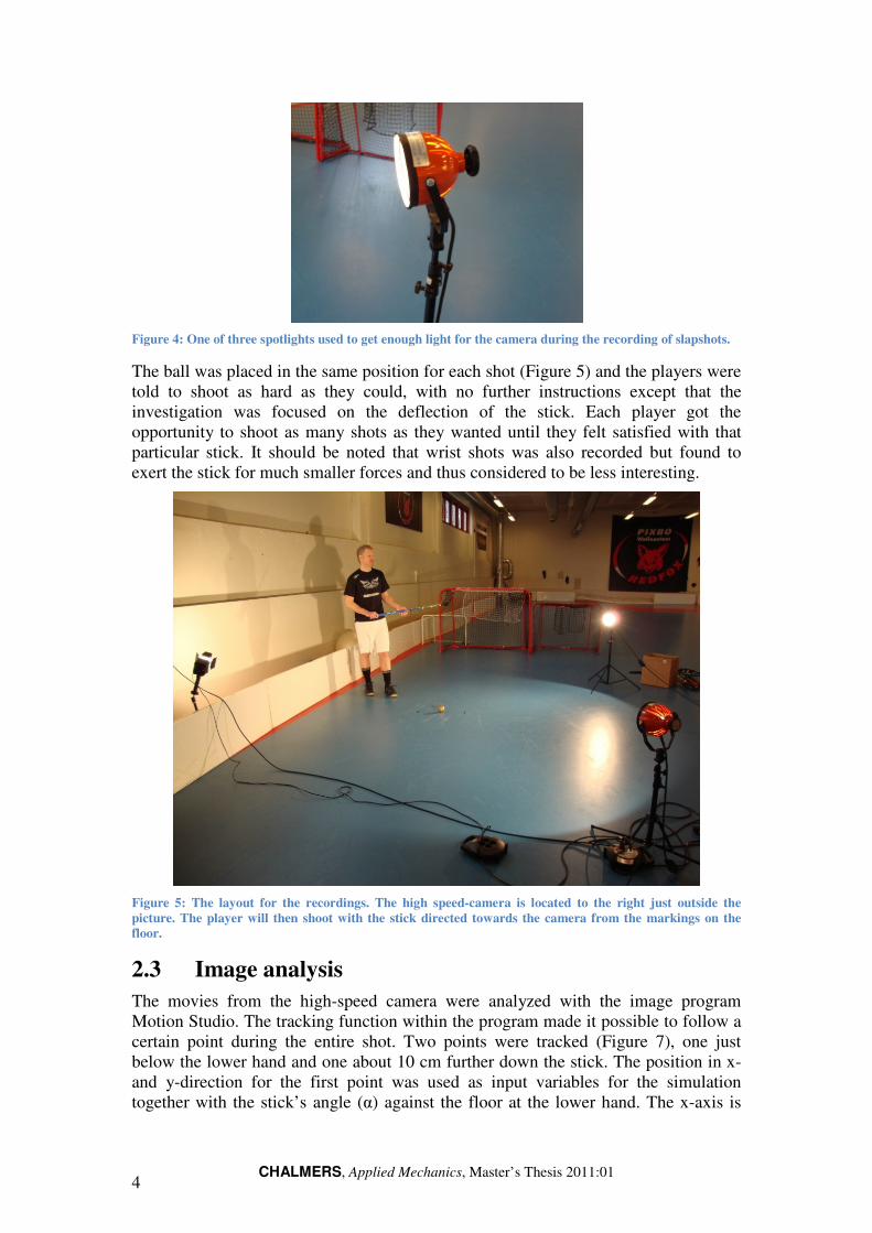
Figure 4: One of three spotlights used to get enough light for the camera during the recording of slapshots.
The ball was placed in the same position for each shot (Figure 5) and the players were told to shoot as hard as they could, with no further instructions except that the investigation was focused on the deflection of the stick. Each player got the opportunity to shoot as many shots as they wanted until they felt satisfied with that particular stick. It should be noted that wrist shots was also recorded but found to exert the stick for much smaller forces and thus considered to be less interesting.
Figure 5: The layout for the recordings. The high speed-camera is located to the right just outside the
picture. The player will then shoot with the stick directed towards the camera from the markings on the
floor.
2.3 Image analysis
The movies from the high-speed camera were analyzed with the image program Motion Studio. The tracking function within the program made it possible to follow a certain point during the entire shot. Two points were tracked (Figure 7), one just below the lower hand and one about 10 cm further down the stick. The position in x- and y-direction for the first point was used as input variables for the simulation together with the stick’s angle (α) against the floor at the lower hand. The x-axis is

CHALMERS, Applied Mechanics, Master’s Thesis 2011:01 5
parallel to the floor and the y-axis is vertical. The hand is considered to move in the plane of x and y, and therefore no measurements were made about the z-axis. The distance was measured by using a calibration image, where a known length was measured within the picture (Figure 6). As initial variable, the angular velocity about the lower hand was chosen.
Figure 6: The calibration image used for the image analysis. Note the input box for the length of the white
line in the image.
Figure 7: The two points used to measure the angle is marked. The first point was just below the hand and
the second was at the end of the grip.
CHALMERS, Applied Mechanics, Master’s Thesis 2011:01 6
2.4 Modelling of standard test
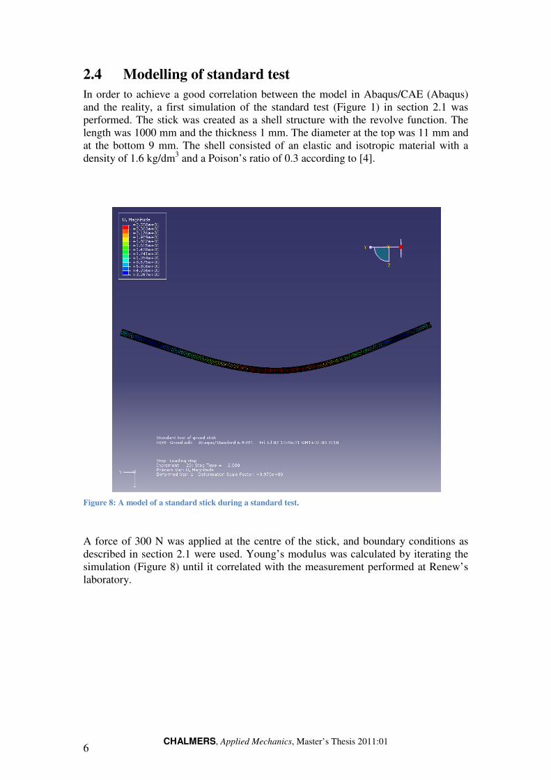
In order to achieve a good correlation between the model in Abaqus/CAE (Abaqus) and the reality, a first simulation of the standard test (Figure 1) in section 2.1 was performed. The stick was created as a shell structure with the revolve function. The length was 1000 mm and the thickness 1 mm. The diameter at the top was 11 mm and at the bottom 9 mm. The shell consisted of an elastic and isotropic material with a density of 1.6 kg/dm3 and a Poison’s ratio of 0.3 according to [4].
Figure 8: A model of a standard stick during a standard test.
A force of 300 N was applied at the centre of the stick, and boundary conditions as described in section 2.1 were used. Young’s modulus was calculated by iterating the simulation (Figure 8) until it correlated with the measurement performed at Renew’s laboratory.

CHALMERS, Applied Mechanics
2.5 Modelling of a slapshot
With the previous model as starting point, the model for the explicit dynamic simulation in Abaqus was created. A floor, consisting of a solid element locked in all degrees of freedom was added to the model,
Figure 9: The floor used in the assembly. It was
The time step was selected to be explicit dynamic in order to keep the parts from the acceleration in consideration. To keep it realistic, but still within reach for completion in a Master’s Thesis, only the part from the lower hand to the floor was used. mainly because it would have created great difficulties with the boundary conditions for the lower hand. Now it about the x- and y-axis. Also, the blade on the deflection of the stick and the floor was assumed to be positioned at the attachment of the blade.between the lower hand and the stick is thus considered as a revolute joint.mentioned above, this joint was locked in the zslapshot naturally moves in all directions. motion in the z-direction in the z-direction for the end of the stickto the boundary conditions
2.5.1 Multi-point constraint
In order to simulate the stiffness of the stick due multi-point constraint (MPC) was implemented at the top 10 cm of the stick. This means that a new point was set at the centre of top perimeter. For the MPC to function, the point needednot to interfere with the behaviour of the stick itself. All of the nodes within 10 cm from the top was chosen and then connected to the centre node with rigid beam elements with no mass as seen in
Applied Mechanics, Master’s Thesis 2011:01
Modelling of a slapshot
With the previous model as starting point, the model for the explicit dynamic n Abaqus was created. A floor, consisting of a solid element locked in all
degrees of freedom was added to the model, Figure 9.
The floor used in the assembly. It was considered a rigid body and locked in all degrees of
freedom.
The time step was selected to be explicit dynamic in order to keep the parts from the acceleration in consideration. To keep it realistic, but still within reach for completion in a Master’s Thesis, only the part from the lower hand to the floor was used. mainly because it would have created great difficulties with the boundary conditions for the lower hand. Now it was instead locked in the z-direction as well as in rotation
axis. Also, the blade was considered not to have a largeon the deflection of the stick and was therefore not taken into consideration. Instead,
assumed to be positioned at the attachment of the blade.between the lower hand and the stick is thus considered as a revolute joint.mentioned above, this joint was locked in the z-direction while the hand d
moves in all directions. However, because of the revolute joint, tof the lower hand was instead added to the original
the end of the stick. This occurred since it was forcedto the boundary conditions and the distance between the lower hand and the floor
point constraint
In order to simulate the stiffness of the stick due to the action of the lower hand, a (MPC) was implemented at the top 10 cm of the stick. This
means that a new point was set at the centre of top perimeter. For the MPC to ed to have a mass. The mass was set to a low number in order
not to interfere with the behaviour of the stick itself. All of the nodes within 10 cm from the top was chosen and then connected to the centre node with rigid beam elements with no mass as seen in Figure 10.
7
With the previous model as starting point, the model for the explicit dynamic n Abaqus was created. A floor, consisting of a solid element locked in all
locked in all degrees of
The time step was selected to be explicit dynamic in order to keep the parts from the acceleration in consideration. To keep it realistic, but still within reach for completion in a Master’s Thesis, only the part from the lower hand to the floor was used. This is mainly because it would have created great difficulties with the boundary conditions
direction as well as in rotation considered not to have a large influence
therefore not taken into consideration. Instead, assumed to be positioned at the attachment of the blade. The joint
between the lower hand and the stick is thus considered as a revolute joint. As direction while the hand during a real
However, because of the revolute joint, the of the lower hand was instead added to the original motion
forced to that due and the distance between the lower hand and the floor.
to the action of the lower hand, a (MPC) was implemented at the top 10 cm of the stick. This
means that a new point was set at the centre of top perimeter. For the MPC to a low number in order
not to interfere with the behaviour of the stick itself. All of the nodes within 10 cm from the top was chosen and then connected to the centre node with rigid beam
CHALMERS, Applied Mechanics, Master’s Thesis 2011:01 8
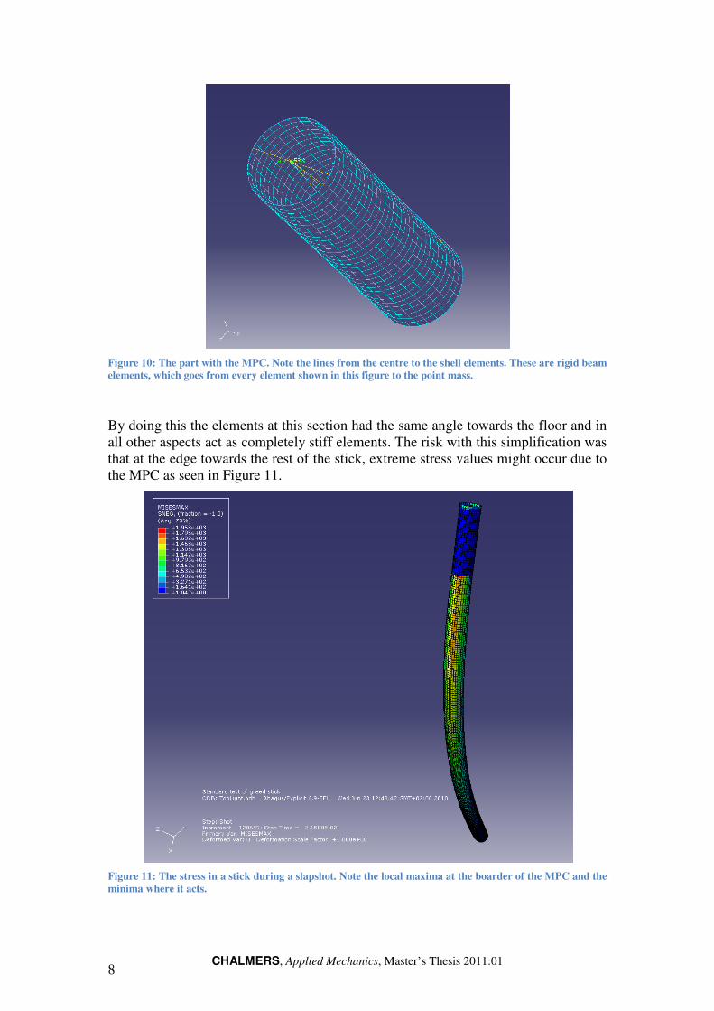
Figure 10: The part with the MPC. Note the lines from the centre to the shell elements. These are rigid beam
elements, which goes from every element shown in this figure to the point mass.
By doing this the elements at this section had the same angle towards the floor and in all other aspects act as completely stiff elements. The risk with this simplification was that at the edge towards the rest of the stick, extreme stress values might occur due to the MPC as seen in Figure 11.
Figure 11: The stress in a stick during a slapshot. Note the local maxima at the boarder of the MPC and the
minima where it acts.

CHALMERS, Applied Mechanics
2.5.2 Inverse identification
Normally, the input in a mechanical problem is the load and the output is the deflection. This study resulted in theinverse identification of the contact force between the floor and the stick, the angle of the stick as well as the position relative to the floorused as input boundary conditions.found and by inverse identification the contact forces could be
Before implementing the original data from the image analysis as input in the simulation, it was plotted in get a smooth input, a function was created and fitted to the original data without singularities. This was done for the motion in xangle between the floor and the stick as seen in
Figure 12: The original data from the image analysis is plotted as a dotted line in grey while the data with
the singularities removed is plotted as a solid black
along the floor, is linear.
Applied Mechanics, Master’s Thesis 2011:01
Inverse identification
Normally, the input in a mechanical problem is the load and the output is the This study resulted in the exact opposite, e.g. an inverse problem. In the ntification of the contact force between the floor and the stick, the angle of
the stick as well as the position relative to the floor taken from the image analysisas input boundary conditions. By applying this into the model, the deflection was
found and by inverse identification the contact forces could be determined
Before implementing the original data from the image analysis as input in the simulation, it was plotted in Excel where several singularities were found. In order to
nput, a function was created and fitted to the original data without singularities. This was done for the motion in x- and y-direction as well as for the angle between the floor and the stick as seen in Figure 12 to Figure 14 .
: The original data from the image analysis is plotted as a dotted line in grey while the data with
the singularities removed is plotted as a solid black line. Note that the motion along the X
9
Normally, the input in a mechanical problem is the load and the output is the an inverse problem. In the
ntification of the contact force between the floor and the stick, the angle of taken from the image analysis was
By applying this into the model, the deflection was determined.
Before implementing the original data from the image analysis as input in the found. In order to
nput, a function was created and fitted to the original data without direction as well as for the
.
: The original data from the image analysis is plotted as a dotted line in grey while the data with
line. Note that the motion along the X-axis, which is

CHALMERS10
Figure 13: The original data from the image analysis is plotted as a dotted line in grey while the data with
the singularities removed is plott
image analysis.
Figure 14: The original data from the image analysis is plotted as a dotted line in grey while the data with
the singularities removed is plot
seconds which means that it has passed the shooter.
The numerical values of each function were calculated for each frame of the recorded slapshot, thus giving the position and anglIt was implemented by using a tabular boundary condition.
CHALMERS, Applied Mechanics, Master’s Thesis 2011:01
The original data from the image analysis is plotted as a dotted line in grey while the data with
the singularities removed is plotted as a solid black line. The large errors are due to problems during the
original data from the image analysis is plotted as a dotted line in grey while the data with
the singularities removed is plotted as a solid black line. Note that the angle becomes negative after 0.041
seconds which means that it has passed the shooter.
The numerical values of each function were calculated for each frame of the recorded slapshot, thus giving the position and angle of the stick for every 1/5000 of a second. It was implemented by using a tabular boundary condition.
The original data from the image analysis is plotted as a dotted line in grey while the data with
due to problems during the
original data from the image analysis is plotted as a dotted line in grey while the data with
the angle becomes negative after 0.041
The numerical values of each function were calculated for each frame of the recorded e of the stick for every 1/5000 of a second.

CHALMERS, Applied Mechanics
3 Results
3.1 Material properties
By iterating until the value from the manual test corresponded Young’s modulus was found to be 49 GPa.
3.2 Dynamic behaviour
The total time that the blade within this time it experiencestates has been made in order to see how well the simulation crecorded slapshot.
At the initial contact with the floorthat actually made it vibratecontinuous motion the vibration of the stick floor.
Figure 15: Comparison between the recorded slapshot and the model at the initial contact with the floor.
Then the deflection of the stick tookoutgoing velocity of the ballthe velocity of the blade as seen in
Applied Mechanics, Master’s Thesis 2011:01
Material properties
By iterating until the value from the manual test corresponded to Young’s modulus was found to be 49 GPa.
Dynamic behaviour
The total time that the blade was in contact with the floor was about 0.04 seconds and within this time it experienced several different states. A comparison of the three main states has been made in order to see how well the simulation corresponds
the initial contact with the floor (Figure 15) there was an impulse through the stick it vibrate, although not visibly for the eye, but due to the
continuous motion the vibration of the stick was dampened by the contac
: Comparison between the recorded slapshot and the model at the initial contact with the floor.
he deflection of the stick took place and that was also the phase where he ball could be affected, that otherwise is in direct relation to
as seen in Figure 16.
11
the simulation,
about 0.04 seconds and several different states. A comparison of the three main
orresponds with the
an impulse through the stick but due to the
dampened by the contact with the
: Comparison between the recorded slapshot and the model at the initial contact with the floor.
also the phase where the in direct relation to

CHALMERS12
Figure 16: Comparison of the recorded slapshot and the model for maximal deflection.
At the end of the slapshot motionthe stick was going upwards again and actedpush on the ball. The relaxation of tension is
Figure 17: Comparison of the recorded slapshot and the model for the relaxation
CHALMERS, Applied Mechanics, Master’s Thesis 2011:01
: Comparison of the recorded slapshot and the model for maximal deflection.
At the end of the slapshot motion, the relaxation of tension occurred. This was when the stick was going upwards again and acted as a spring and thereby
ball. The relaxation of tension is compared in Figure 17.
: Comparison of the recorded slapshot and the model for the relaxation of tension.
occurred. This was when ereby gave an extra
of tension.

CHALMERS, Applied Mechanics, Master’s Thesis 2011:01 13
3.3 Contact forces
In Figure 18 the contact force between the floor and the stick can be seen. It shows an early peak due to the first impact with the floor, and goes to zero again because of the vibration from the impact. Then the pressure against the floor increases gradually until it peaks after about 0.038 seconds when it is released from the floor and the spring-effect within the stick gives an additional velocity to the ball. Compare with Figure 15 to Figure 17 above.
Figure 18: Contact force between the floor and the stick.
This shows that if a stick is excerted to a force of 700 N at the position of the blade, it will behave as if shooting a slapshot. If excerting one stick to this several times, it will show how many shots it can do without deforming or breaking which is an important quality factor.
0
100
200
300
400
500
600
700
800
900
0 0,005 0,01 0,015 0,02 0,025 0,03 0,035 0,04 0,045 0,05
Co
nta
ct f
orc
e [
N]
Time [s]
CHALMERS14
4 Discussion
Since there has been no use of finite element analysis wibefore, the possibilities for development are substantial. But one must then keep in mind that it is a small industry andis quite large for the companies within floorball.comparison with the cost of a trial and error for new designs.
The result of this report shows that the methodinvestigations. With the use of a high speed camera and a program for simusing finite element methodnot all. Due to the direct feedback relation between the two parts of the method, one can validate the material model used for the simulation and also analyze new dof sticks. With this direct feedback it be more confident that they are repfor other implementations, such as golf and tennis equipment if one stays within the sports industry, but also for all other kinds where you want to verify an initial model before you start to implement it in a furt
Although the outcome of this report is more focused on the general methoddoes not mean that the numerical results and discoveirrelevant. The maximal contact force, gives a guiding line to how much tneeds to withstand when subjected to maximal deflection.test it for fatigue.
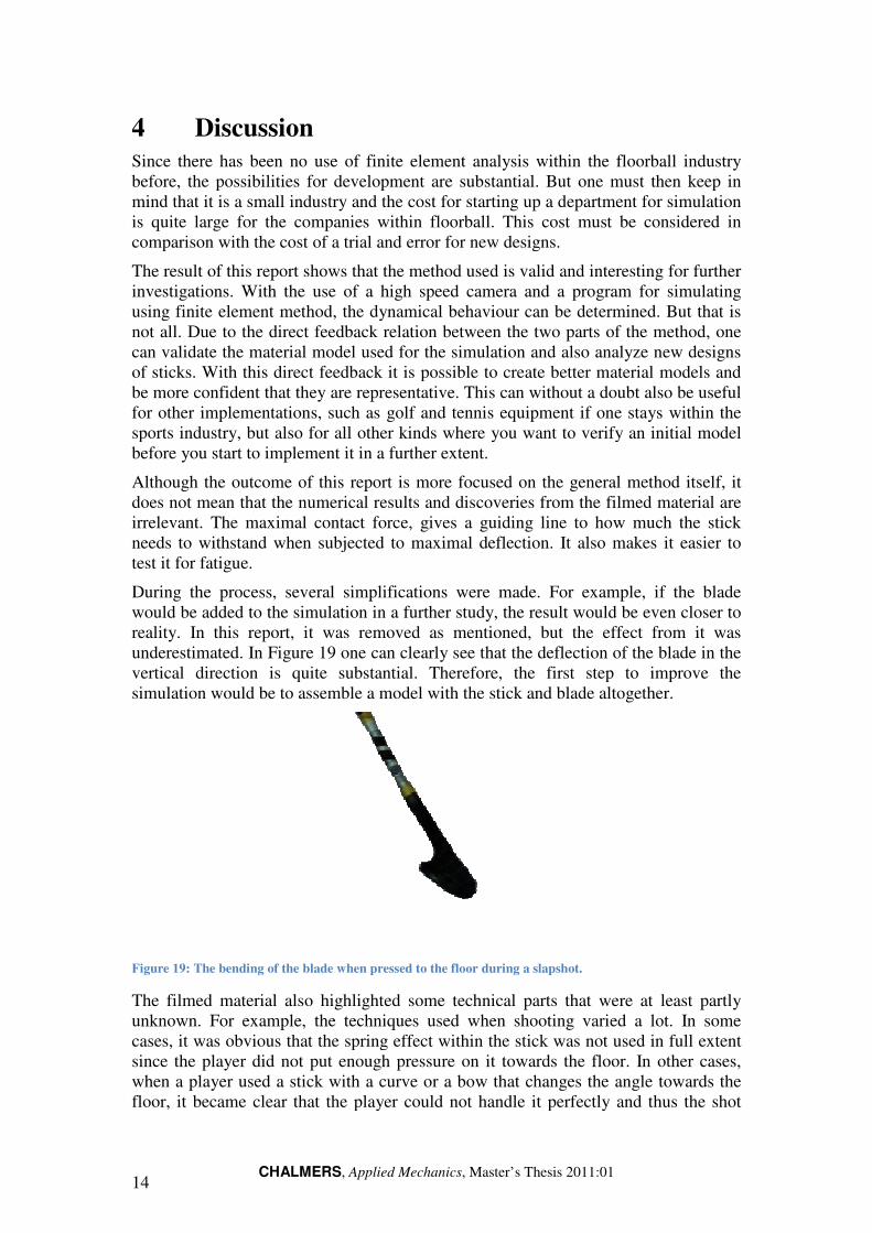
During the process, several simplifications were made. would be added to the simulation in a further study, the result would be even closer to reality. In this report, it was removed as mentioned, but the effect from it was underestimated. In Figure vertical direction is quite substantial.simulation would be to assemble a model with the stick and blade altoge
Figure 19: The bending of the blade when pressed to the floor during a slapshot.
The filmed material also highlightunknown. For example, the techniques used when shooting vacases, it was obvious that the spring effect within the stick was not used in full extent since the player did not put enough pressure on it towards the floor. In other cases, when a player used a stick with a curve or a bow that changefloor, it became clear that the player could not handle it perfectly and thus the shot
CHALMERS, Applied Mechanics, Master’s Thesis 2011:01
Since there has been no use of finite element analysis within the floorball industry before, the possibilities for development are substantial. But one must then keep in
that it is a small industry and the cost for starting up a department for simulation is quite large for the companies within floorball. This cost must be considered in comparison with the cost of a trial and error for new designs.
The result of this report shows that the method used is valid and interesting for further investigations. With the use of a high speed camera and a program for sim
finite element method, the dynamical behaviour can be determined. But that is not all. Due to the direct feedback relation between the two parts of the method, one can validate the material model used for the simulation and also analyze new d
With this direct feedback it is possible to create better material models and be more confident that they are representative. This can without a doubt also be useful for other implementations, such as golf and tennis equipment if one stays within the sports industry, but also for all other kinds where you want to verify an initial model before you start to implement it in a further extent.
Although the outcome of this report is more focused on the general methoddoes not mean that the numerical results and discoveries from the filmed material are
The maximal contact force, gives a guiding line to how much tneeds to withstand when subjected to maximal deflection. It also makes it easier to
During the process, several simplifications were made. For example, iwould be added to the simulation in a further study, the result would be even closer to reality. In this report, it was removed as mentioned, but the effect from it was
Figure 19 one can clearly see that the deflection of the blade in the vertical direction is quite substantial. Therefore, the first step to improve the simulation would be to assemble a model with the stick and blade altoge
: The bending of the blade when pressed to the floor during a slapshot.
The filmed material also highlighted some technical parts that wereFor example, the techniques used when shooting varied a lot. In some
cases, it was obvious that the spring effect within the stick was not used in full extent since the player did not put enough pressure on it towards the floor. In other cases, when a player used a stick with a curve or a bow that changes the angle towards the floor, it became clear that the player could not handle it perfectly and thus the shot
thin the floorball industry before, the possibilities for development are substantial. But one must then keep in
department for simulation is cost must be considered in
is valid and interesting for further investigations. With the use of a high speed camera and a program for simulating
, the dynamical behaviour can be determined. But that is not all. Due to the direct feedback relation between the two parts of the method, one can validate the material model used for the simulation and also analyze new designs
possible to create better material models and This can without a doubt also be useful
for other implementations, such as golf and tennis equipment if one stays within the sports industry, but also for all other kinds where you want to verify an initial model
Although the outcome of this report is more focused on the general method itself, it ries from the filmed material are
The maximal contact force, gives a guiding line to how much the stick It also makes it easier to
For example, if the blade would be added to the simulation in a further study, the result would be even closer to reality. In this report, it was removed as mentioned, but the effect from it was
one can clearly see that the deflection of the blade in the Therefore, the first step to improve the
simulation would be to assemble a model with the stick and blade altogether.
ed some technical parts that were at least partly ried a lot. In some
cases, it was obvious that the spring effect within the stick was not used in full extent since the player did not put enough pressure on it towards the floor. In other cases,
the angle towards the floor, it became clear that the player could not handle it perfectly and thus the shot

CHALMERS, Applied Mechanics, Master’s Thesis 2011:01 15
velocity was decreased. Of course, for the later example there were also examples of the opposite. With this being said, it is possible to use the high speed camera as a test of which stick is suited for your shooting technique or if you need to adapt your technique in order to get the full performance out of the stick.
CHALMERS, Applied Mechanics, Master’s Thesis 2011:01 16
5 Conclusion
With some simplifications, it was possible to resemble the dynamic behaviour of a slapshot in a finite element model with the help of a high speed camera. This also gave the possibility to receive direct feedback between the two thus validating the material models. The method itself can be refined and used in many applications were dynamic behaviour during high speed is investigated.
This material model of the stick showed that during a slapshot, the maximal force that the stick was exerted to was 700 N in comparison to the 300 N that is used for the standard test.

CHALMERS, Applied Mechanics, Master’s Thesis 2011:01 17
6 References
[1] Innebandy.se (20100825) Official site for Swedish floorball, http://www.innebandy.se/sv/Om-innebandy/
[2] IFF (20100825) Official site for the International Floorball Federation, http://www.floorball.org/default.asp?sivu=2&alasivu=205&kieli=826
[3] Strömberg, Joakim, Renew Group AB, “Personal communication”, 2010
[4] Performance Composites Ltd (20100410) http://www.performance-composites.com/carbonfibre/mechanicalproperties_2.asp