analytical solution for micropile design under tension and ... · the micropiles are classified...
TRANSCRIPT

Analytical solution for micropile design under
tension and compression
ANIL MISRA$ and C.-H. CHEN
University of Missouri-Kansas City, Kansas City, Missouri, U.S.A.
(Received 8 October 2001; revised 12 November 2002; accepted 11 April 2003)
Abstract. Micropiles are being increasingly utilized in foundation rehabilitation and seismicretrofitting projects. The function of the micropiles in these projects is to enhance the founda-
tion ultimate capacity as well as reduce foundation deflection. This paper focuses on an ana-lytical model for micropile load-displacement behavior subjected to compressive as well astensile loading. The soil-micropile interaction is considered explicitly in the model develop-
ment. Furthermore, to keep the model simple and accessible to designers, the micropile-soilinterface is assumed to be linearly elastic-perfectly plastic and homogeneous with depth.Closed form expressions of micropile deformation as a function of applied load are presented.
These expressions are used to study the effect of model parameters on micropile yield beha-vior. Micropile strain distribution and the load transfer behavior calculated by the modelare discussed. The model calculations are compared with the field measured load-displacementcurves. The measured micropile load-displacement data available in the literature are analyzed
to evaluate the model parameters.
Key words. foundation retrofit, load-displacement relation, micropiles, pullout behavior,soil-structure interaction.
Notation
The following symbols are used in this paper:
D ¼micropile diameter, mm;dP/du ¼micropile initial stiffness, kN/m;Es ¼ soil elastic modulus, kN/m2;K ¼ shear modulus of micropile-soil interface, kN/m2;Kc ¼ axial stiffness of debond zone, MN;Km ¼micropile axial stiffness, MN;Ks ¼micropile tip soil stiffness, kN/m;Lb ¼ bond length, m;Lc ¼ casing depth, m;Ld ¼ debond length, m;P ¼micropile load, kN;Pt ¼micropile tip resistance force, kN;
$Corresponding author: Professor of Civil Engineering, University of Missouri-Kansas City, 5100
Rockhill Road, 350H Flarsheim Hall, Kansas City, MO 64110, U.S.A. e-mail: [email protected]
Geotechnical and Geological Engineering 22: 199–225, 2004. 199# 2004 Kluwer Academic Publishers. Printed in the Netherlands.

Pu ¼micropile ultimate pullout capacity, kN;q ¼ shear force per unit length, kN/m;qo ¼ yield strength of micropile-soil interface, kN/m;u ¼ displacement, mm;uo ¼ interface displacement at yield, mm;ut ¼ tip displacement, mm;�u ¼ deformation at micropile top, mm;U ¼ non-dimensional displacement;�U ¼ non-dimensional displacement at top of bond zone;x ¼ location along the micropile length;a ¼ normalizing factor, cm;b ¼ non-dimensional factor;l ¼ scaling factor;ms ¼ tip soil Poisson’s ratio;tu ¼ ultimate shear strength of micropile-soil interface, kN/m2;x ¼ non-dimensional length; andxo ¼ location of transition point.
1. Introduction
Micropiles are being increasingly utilized in foundation rehabilitation projects. These
drilled, cast-in-place, small diameter grouted piles are especially suited for founda-
tions with difficult access, restricted clearance and poor ground conditions, wherein
minimal disturbance to the existing structure is permissible (FHWA 1997). Given
their ease of installation, micropiles have been used for retrofitting and rehabilitation
of existing foundations. For example, in seismic retrofits, a function of the micropiles
is to enhance the pullout capacity of the existing foundation system, and minimize
the vertical deflection of the structures in a seismic event (Taylor et al. 1998, Zelenko
et al. 1998, and Misra et al. 1999). Micropiles have also been used to enhance the
overall capacity and reduce deflections of existing foundations subjected to compres-
sion and pullout (Mascardi 1982, Laefer 1999, Bruce et al. 1999 and IWM99 1999).
Micropiles are designed to not only bear the ultimate load but also to limit the dis-
placement of a structure, especially when used for retrofitting and rehabilitation of
existing foundations. Therefore, the complete load-displacement behavior is of sig-
nificance for micropile design. The current design practice for micropiles is based
upon either the methods developed for large diameter drilled shafts and ground
anchors or simplistic interpretation of micropile load tests similar to the approach
used for analyzing tieback anchors (FHWA 1997, 2000). However, not only the cons-
truction methods for micropiles but also the micropile structural characteristics and
the interaction of micropile-soil interface differ significantly from both drilled shafts
and ground anchors. Consequently, the methods and the parameters used for drilled
shafts and ground anchors are not directly applicable. For instance, the numerical
‘t-z’ method developed for large diameter drilled shafts is not recommended for
micropiles because of the difficulty in the selection of design parameters due to the
200 ANIL MISRA AND C.-H. CHEN
structural characteristics of micropile and micropile-soil interaction (FHWA
2000). Therefore, simple closed-form analytical expressions based upon mathemati-
cal models that explicitly describe micropile structural characteristics and
micropile-soil interaction could benefit the designer in investigating the micropile
load-displacement behavior.
This paper presents closed-form analytical relationships for micropile load-
displacement behavior that are derived by explicitly considering the micropile-soil
interaction. To keep the analytical relationships simple and accessible to designers,
the micropile-soil interface is assumed to be linearly elastic-perfectly plastic and
homogeneous with depth. As a result, analytical expressions are obtained for micro-
pile deformation as a function of applied load. In addition, the model parameters are
combined to obtain three scaling and normalization factors that are found to signif-
icantly influence the micropile load-displacement behavior. The closed-form expres-
sions are used to study the effect of model parameters on micropile yield behavior.
Micropile strain distribution and the load transfer behavior calculated by the
model are discussed. The model calculations are compared with field measured load-
displacement curves.
2. Description of Micropile Foundation
Micropile foundations are cast-in-place small diameter pile foundations whose dril-
led diameter, typically, varies from 0.1m to 0.3m. Structurally, micropiles derive a
large portion of their stiffness and strength from high-capacity steel reinforcement
elements, which may occupy as much as 50% of the bore volume. The load carrying
mechanisms and construction methodology are other characteristics that distinguish
micropiles from other cast-in-place pile foundations.
Based upon the load carrying mechanism, the micropiles are classified into two
cases (FHWA 1997). Case 1 micropiles are those whose capacity is mainly derived
from the single pile-soil interaction mechanism. When grouped in close proximity,
Case 1 micropiles may exhibit some group action akin to that of cast-in-place piles.
Case 2 micropiles, on the other hand, are networks of reticulated piles that create a
system of confined soil composite with micropiles acting as reinforcing elements. All
micropiles installed in North America are Case 1 piles. Micropiles are further clas-
sified based upon the construction method. Typically the micropiles are constructed
in the following three steps: (1) drilling and casing borehole, (2) placing reinforce-
ment, and (3) injecting grout. Based upon the variations in these three basic steps,
the micropiles are classified into four types and several subtypes (FHWA 1997,
Schaefer et al. 1997). For the model development described in this paper, only those
micropiles are considered that may be classified as Case 1 based upon the load car-
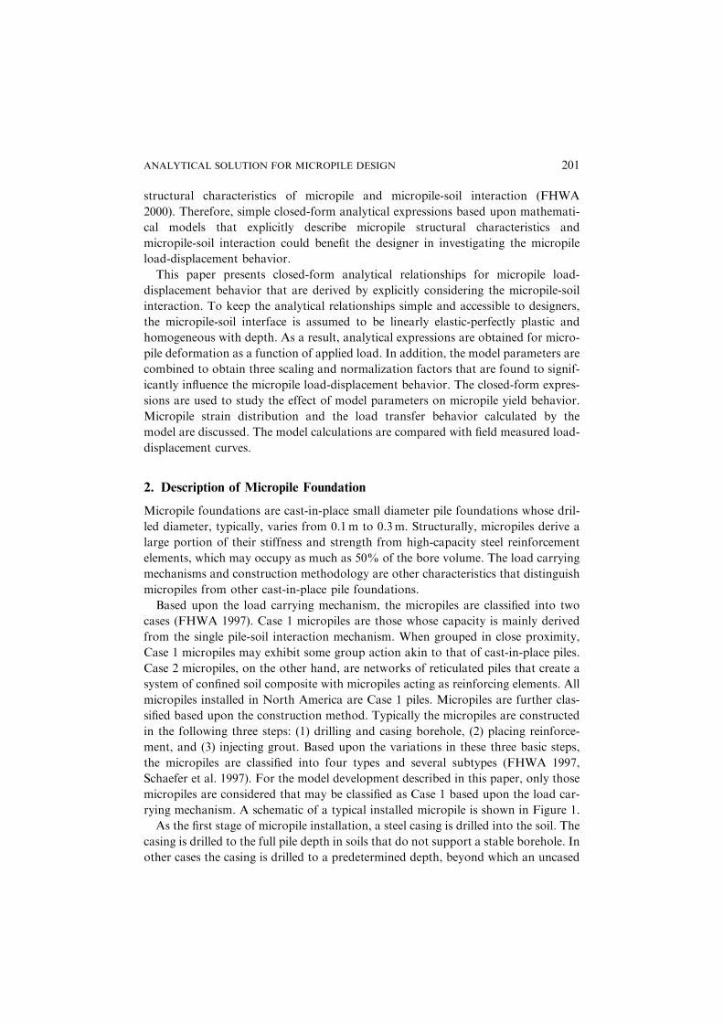
rying mechanism. A schematic of a typical installed micropile is shown in Figure 1.
As the first stage of micropile installation, a steel casing is drilled into the soil. The
casing is drilled to the full pile depth in soils that do not support a stable borehole. In
other cases the casing is drilled to a predetermined depth, beyond which an uncased
ANALYTICAL SOLUTION FOR MICROPILE DESIGN 201
borehole is drilled to the full pile depth. In some cases, drilling slurries may be used
to stabilize the uncased borehole. In order to verify the borehole is clear of cuttings,
pile depth is typically measured while placing the grout tremie tube and the reinfor-
cing bar. Any drill cuttings that have settled at the borehole bottom are removed by
reflushing the borehole. Once the borehole has been advanced and cleaned to
full-depth, the reinforcing bar, with any attached post grout tubes, is placed along
with centralizers. The casing is then tremie filled with neat cement grout from the
tip to the top of the pile. For some Type B micropiles, the borehole may be first filled
with grout and the rebar installed as the next step. Subsequently, the casing is
removed in sections from the tip of the pile to top of the bond zone, if necessary.
During or at the end of casing removal, the grout is pressurized to subject the micro-
pile bond zone to pressure with the intent of enhancing pile bonding with the adja-
cent soil. For Type D micropiles, the installed pile is post-grouted by pumping neat
cement grout through the pre-installed post grout tubes. The post grout first frac-
tures the initial grout, and subsequently, injects into the surrounding soil. The grout
water-cement ratio used in most applications for primary grout is from 0.4 to 0.5 by
weight. The grout compressive strength is typically in excess of 25MN/m2.
3. Micropile-soil Interaction Model
The micropile-soil interaction is schematically shown in Figure 1 and the load trans-
fer mechanism is depicted in Figure 2. It is assumed that the load-transfer to the
ground occurs through the soil-grout interface of the micropile as represented by
spring-slider system in Figure 2. Similar assumptions are commonly made for ana-
lytical and numerical models for load-displacement behavior (or the so called ‘t-z’
curves) of piles and drilled shafts (cf. Scott 1981, Kraft et al. 1981, Baguelin et al.
1982, Reese and O’Neill 1987, Juran and Christopher 1989, and FHWA 1993).
Figure 1 Schematic of soil-micropile interaction
202 ANIL MISRA AND C.-H. CHEN

As shown by the shaded zone in Figure 1 at the micropile-soil interface, it is
assumed that a soil-grout shear-boundary layer is formed as the micropile is subjected
to loading. For the discussions in this paper, the micropile-soil interface (soil-grout
shear boundary layer) is assumed to behave as an ideal elastic-plastic material, both
in drained and undrained conditions, as depicted by the shear force per unit length q,
versus displacement u, curve in Figure 3. Here K is the shear modulus of the micro-
pile-soil interface, qo is the yield strength of the micropile-soil interface given by the
product of pile perimeter pD and the ultimate shear strength of micropile-soil inter-
face in drained or undrained conditions denoted by tu, and uo¼qo/K is the interface
displacement at yield. The micropile-soil interface parameters, K and tu, are the prop-
erties of the soil-grout shear-boundary layer. In general, these are not directly deter-
mined from the soil parameters, but also depend upon the grout properties, grout
pressure and construction techniques. In addition, the micropile-soil interface para-
meters, K and tu may not necessarily follow the stratification of the natural soil.
Figure 3 Soil shear boundary layer behavior
Figure 2 Spring and slider model for micropile-soil interface
ANALYTICAL SOLUTION FOR MICROPILE DESIGN 203

Therefore, for simplicity of analysis, a homogeneous soil-grout shear-boundary layer
is assumed. The advantage of this analysis is that the constant values of K and tu can
be used as average micropile-soil interface parameters.
Given the manner in which micropiles are installed, the load transfer occurs
mostly via the soil-grout shear boundary layer in the bond zone Lb. The remainder
of the soil-micropile interface is considered to be debonded or having negligible shear
resistance. In many cases, the debonded length Ld typically extends to the casing
depth Lc. However, the debonded length can be longer than the casing depth in cases
where grouting is ineffective or shorter than the casing depth in cases where casing is
plunged into the bond zone. As the micropile is subjected to loading, the soil-grout
shear boundary layer in the bond zone Lb first deforms elastically. Subsequently, the
shear boundary layer begins to yield as the load is increased further. The boundary
layer yield initiates at the top of the bond zone and progresses to the bottom of the
micropile as depicted in Figure 1. The micropile itself is assumed to behave elastically
throughout considering that the load required to reach the soil-grout shear boundary
layer yield strength is much smaller than that required to yield the cement grout or
micropile reinforcement (Misra and Chen 2002).
In the subsequent discussion, the load-displacement relationship under the elastic
micropile-soil interaction regime is first presented. The load displacement relationship
under elasto-plastic micropile-soil interaction regime is then discussed. The analysis
described below follows the procedure presented by Scott (1981) in the context of pile
analysis. For completeness of the discussion, the seminal equations required for the
analysis and derived results that are of relevance to micropile design are presented.
3.1. ELASTIC MICROPILE-SOIL INTERACTION
Consider the free body diagram of slice Dx at location x along the pile as shown in
Figures 1 and 4a. Under elastic deformation of the micropile-soil interface, the force
balance of the micropile-soil interaction of slice Dx is given by the following equili-
brium equation:
qðxÞ � KuðxÞ ¼ 0 ð1Þ
where, qðxÞ is the shear force per unit length along the pile, K is the shear modulus of
the micropile-soil interface, and uðxÞ is the pile deformation at that location. Denot-
ing the micropile axial stiffness to be Km (defined in force unit), the axial force in the
pile is given by Km du/dx and hence, the shear force per unit length qðxÞ is obtained
to be
qðxÞ ¼ Kmd2u
dx2ð2Þ
Using a non-dimensionalized length x¼ x/Lb, the governing Equation 1 may be
written as
d2u
dx2� l2uðxÞ ¼ 0 for 04x4 1 ð3Þ
204 ANIL MISRA AND C.-H. CHEN

where scaling factor l is given by
l2 ¼KL2
b
Kmð4Þ
Micropile behavior under pullout
Under pullout, the following closed form solution of Equation 3 may be obtained,
given that themicropile has a zero force at the tip and has an applied force P at the top:
uðxÞ ¼PLb
Km
cosh lxl sinh l
for 04x4 1 ð5Þ
The micropile deformation may be normalized as follows:
UðxÞ ¼1
auðxÞ ¼
P
Pu
cosh lxl sinh l
for 04x4 1 ð6Þ
using the normalizing factor, a, given as
a ¼PuLb
Kmð7Þ
where Pu is the micropile ultimate pullout capacity. Thus, the scaled micropile dis-
placement at the top of the bond zone (x¼ 1) may be written as:
�U ¼P
Pu
cosh ll sinh l
ð8Þ
Using the closed form solution Equation 5 and considering the deformation of the
debonded portion of micropile with axial stiffness to be Kc (defined in force units),
the elastic deformation, �u, at the top of the micropile under an applied load, P, is
obtained as
�U ¼PLb
Km
cosh ll sinh l
þPLd
Kcð9Þ
Micropile behavior under compression
Under compression, the micropile may develop a tip resistance force Pt proportional
to the tip displacement ut given by
Pt ¼ Ksut ð10Þ
whereKs is the tip soil stiffness (defined in force/length units). Although the proportion
ofmicropile load carried through the tip is usually small due to the geometry of amicro-
pile, the tip resistance is seen to significantly influence the overall load-displacement
behavior of the micropile as discussed later in Section 4.2. Based upon theories for
rigid punch bearing upon an elastic half-space, the tip soil stiffness, Ks, may be rela-
ted to micropile diameter and elastic properties of tip soil as follows (Johnson 1985):
ANALYTICAL SOLUTION FOR MICROPILE DESIGN 205

Ks ¼0:3pDEs
ð1� m2s Þð11Þ
where Es is the tip soil elastic modulus and ms is tip soil Poisson’s ratio.
Considering that the micropile has an applied force P at the top and a tip force
given by Equation 10, Equation 3 may be solved to obtain the following expression
for normalized micropile deformation:
UðxÞ ¼1
auðxÞ ¼
P
Pu
cosh lxþ bl sinh lxlðsinh lþ bl cosh lÞ
for 04x4 1 ð12Þ
where non-dimensional factor, b, is given as
b ¼Ks
KLbð13Þ
Thus, the elastic deformation, �u, at the top of the micropile under an applied load, P,
is obtained as
�u ¼PLb
Km
cosh lþ bl sinh llðsinh lþ bl cosh lÞ
þPLd
Kcð14Þ
and at the tip of the micropile
�u ¼PLb
Km
1
lðsinh lþ bl cosh lÞð15Þ
3.2. ELASTO-PLASTIC MICROPILE-SOIL INTERACTION
As the load on the micropile is increased, the soil-grout shear boundary layer begins
to yield from the top of the bond zone towards the bottom of the micropile as depic-
ted by the plastic zone in Figure 1. Now, consider the free body diagrams of slices Dx
at location x in the elastic and plastic zones along the pile shown in Figure 1. The
force balance of the micropile-soil interaction of slice Dx in the elastic zone, depicted
in Figure 4(a), is given by the following equilibrium equation:
Figure 4 Free body diagram of slice Dx in the (a) elastic zone, and (b) plastic zone
206 ANIL MISRA AND C.-H. CHEN

qðxÞ � KuðxÞ ¼ 0 ð16Þ
where, qðxÞ is the shear force per unit length along the pile, K is the shear modulus of
the micropile-soil interface, and uðxÞ is the pile deformation at that location. Simi-
larly, the force balance of the micropile-soil interaction of slice Dx in the plastic zone,
depicted in Figure 4(b), is given by the following equilibrium equation
qðxÞ � qo ¼ 0 ð17Þ
where qo is the yield strength of the micropile-soil interface given by the product of
pile perimeter pD and the ultimate shear strength of micropile-soil interface denoted
by tu. Again, considering the micropile stiffness, Km and non-dimensionalized length
x¼x/Lb, the equilibrium Equations 16 and 17 may be written as
d2u
dx2� l2uðxÞ ¼ 0 for 04x4xo ð18Þ
and
d2u
dx2� l2uo ¼ 0 for xo 4x4 1 ð19Þ
where scaling factor l is given by Equation 4, soil displacement at yield uo¼qo/K, and
xo locates the transition from elastic to plastic zone along the micropile. To satisfy
continuity of displacement at the transition point xo, the following boundary condi-
tions must be satisfied:
u xoð Þ½ �E¼ u xoð Þ½ �
P anddu xoð Þ
dx
� �E
¼du xoð Þ
dx
� �P
ð20Þ
where superscript E refers to the elastic zone and superscript P refers to the plastic
zone of the micropile as described by Equations 18 and 19, respectively.
Micropile behavior under pullout
Under pullout, Equations 18 and 19 may be solved analytically to yield the following
expressions for normalized micropile deformation in the bond zone:
UðxÞ ¼1
auðxÞ ¼
cosh lx
l2 cosh lxo
for 04x4xo ð21Þ
and
UðxÞ ¼1
auðxÞ ¼
1
2x2 � x2o� �
� 1�P
Pu
� �x� xo
� �þ
1
l2for xo 4x4 1 ð22Þ
The normalized micropile displacement at the top of the bond zone (x¼ 1) may be
written as:
ANALYTICAL SOLUTION FOR MICROPILE DESIGN 207
�U ¼1
21� x2o� �
� 1�P
Pu
� �1� xo
� �þ
1
l2for 04xo 4 1 ð23Þ
Further, the condition of continuity of displacements at the elastic to plastic transi-
tion point yields the following identity, which can be solved for a given load P to
obtain the location of transition point xo:
xo � 1ð Þ �tanh lxo
lþ
P
Pu¼ 0 ð24Þ
As seen from Equation 24, the yielding behavior of the micropile-soil interface not
only depends upon the load ratio P/Pu, it also depends upon the scaling factor l that
embodies the effects of micropile bond length, micropile-soil interface stiffness and
micropile stiffness.
Now, using the closed form solution Equation 22 and considering the deformation
of the debonded portion of micropile with axial stiffness Kc, the deformation, �u, at
the top of the micropile under an applied load, P, is given as
�u ¼1
2
qoL2b
Km1� x2o� �
�Lb qoLb � Pð Þ
Km1� xoð Þ þ uo þ
PLd
Kcfor 04xo 4 1
ð25Þ
Further, when xo reaches 0, the soil shear boundary layer has completely yielded
and the micropile is unable to sustain any further load. Thus from Equation 17, the
micropile ultimate pullout capacity Pu may be obtained as the following well known
expression available in text books for pile design (for example Coduto 2001):
Pu ¼ pDLbtu ð26Þ
where tu is the ultimate micropile-soil interface shear strength, Lb is the micropile
bond length and D is the micropile diameter.
Micropile behavior under compression
Under compression, Equations 18 and 19 yield the following expressions for normal-
ized micropile deformation in the bond zone:
UðxÞ ¼1
auðxÞ ¼
cosh lxþ bl sinh lx
l2 cosh lxo þ bl sinh lxoð Þfor 04x4xo ð27Þ
and
UðxÞ ¼1
auðxÞ ¼
1
2x2 � x2o� �
� 1�P
Pu
� �x� xo
� �þ
1
l2for xo 4x4 1 ð28Þ
The condition of continuity of displacements at the elastic to plastic transition point
yields the following identity, which can be solved for a given load P to obtain the
location of transition point xo:
208 ANIL MISRA AND C.-H. CHEN

xo � 1ð Þ �tanh lxo
lþ
P
Pu�
1
cosh lxo
bcosh lxo þ bl sinh lxo
� �¼ 0 ð29Þ
From Equation 29, it is seen that the yielding behavior of the micropile-soil interface
not only depends upon the load ratio P/Pu, it also depends upon the scaling factor land the non-dimensional factor b that embody the effects of micropile bond length,
micropile stiffness, micropile-soil interface stiffness, and tip soil stiffness. It is note-
worthy that Equations 22 and 28 are identical, hence, the scaled micropile displace-
ment, �U, at the top of the bond zone (x¼1) and the deformation, �u, at the top of the
micropile under an applied compressive load, P, are given by Equations 23 and 25.
When the micropile-soil interface yields completely (i.e. xo ¼ 0), the tip carries the
additional applied load and the normalized micropile deformation is given by:
UðxÞ ¼1
auðxÞ ¼
1
2x2 þ
P
Pu� 1
� �xþ
P
Pu� 1
� �1
l2bfor 04x4 1 ð30Þ
When the tip force, Pt, calculated from Equation 10, reaches the tip bearing capacity,
the micropile fails in compression. Micropile tip bearing capacity may be obtained
from bearing capacity theories for pile foundations assuming a punching shear fail-
ure (see for example Coduto 2001).
4. Model Parameters and Scaling Factors
The model parameters may be categorized into those related to micropile-soil inter-
face properties and those related to micropile properties. The micropile-soil interface
properties are the ultimate shear strength of micropile-soil interface, tu, the shear
modulus of micropile-soil interface, K, and the tip soil stiffness Ks. The micropile
properties include micropile diameter, D, bond length, Lb, debond length, Ld, micro-
pile axial stiffness in bond zone, Km, and micropile axial stiffness in debond zone, Kc.
The model parameters may be combined to obtain three scaling and normalization
factors, a¼PuLb/Km, b¼Ks/KLb, and l ¼
ffiffiffiffiffiffiffiffiffiffiffiffiffiffiffiffiffiffiKL2
b=Km
q, which profoundly influence
the micropile load-displacement behavior.
4.1. DETERMINATION OF MODEL PARAMETERS
The model parameters related to micropile-soil interface properties have a complex
dependency upon the soil properties, grout properties, grout pressure and construc-
tion techniques. Therefore, the model parameters may be obtained by analyzing the
measured micropile load-displacement curve obtained from a load test at a given
installation. Furthermore, a database of these parameters may be established for a
wide variety of soil conditions, grout properties, grout pressure and construction
techniques. These model parameters may then be utilized to guide and refine the
micropile design for a given project. The following discussion describes a method
to obtain the model parameters from a measured load-displacement curve.
ANALYTICAL SOLUTION FOR MICROPILE DESIGN 209

Figure 5 shows a measured micropile load-displacement curve depicted by sym-
bols (Misra et al. 1999), and a calculated curve, using Equation 25, depicted by a
solid line. The model parameters are related to the ultimate micropile pullout
capacity, Pu, and initial micropile stiffness, dP/du, shown in Figure 5. It is noted that
once the micropile-soil interface yields completely, a sudden failure occurs at ulti-
mate micropile pullout capacity Pu. The sudden failure is a manifestation of the
assumption that soil-shear boundary layer behaves as an ideal elasto-plastic mate-
rial. As seen, the calculated curve replicates the measured behavior reasonably well.
The micropile ultimate pullout capacity Pu may be used to compute the ultimate
average micropile-soil interface shear strength tu from Equation 26, for a given
micropile diameter and bond length. The micropile diameter may be estimated as
the borehole diameter or the casing diameter with some tolerance to allow for any
irregularities in the borehole. The bond length may be taken as the difference
between borehole depth and the casing depth, however, the actual bond length is dif-
ficult to gauge in practice. In some cases the pressurized grout may seep above the
casing resulting in a longer bond length than intended. In other cases, perfect bond-
ing may not be achieved over all the soil strata resulting in a shorter bond length
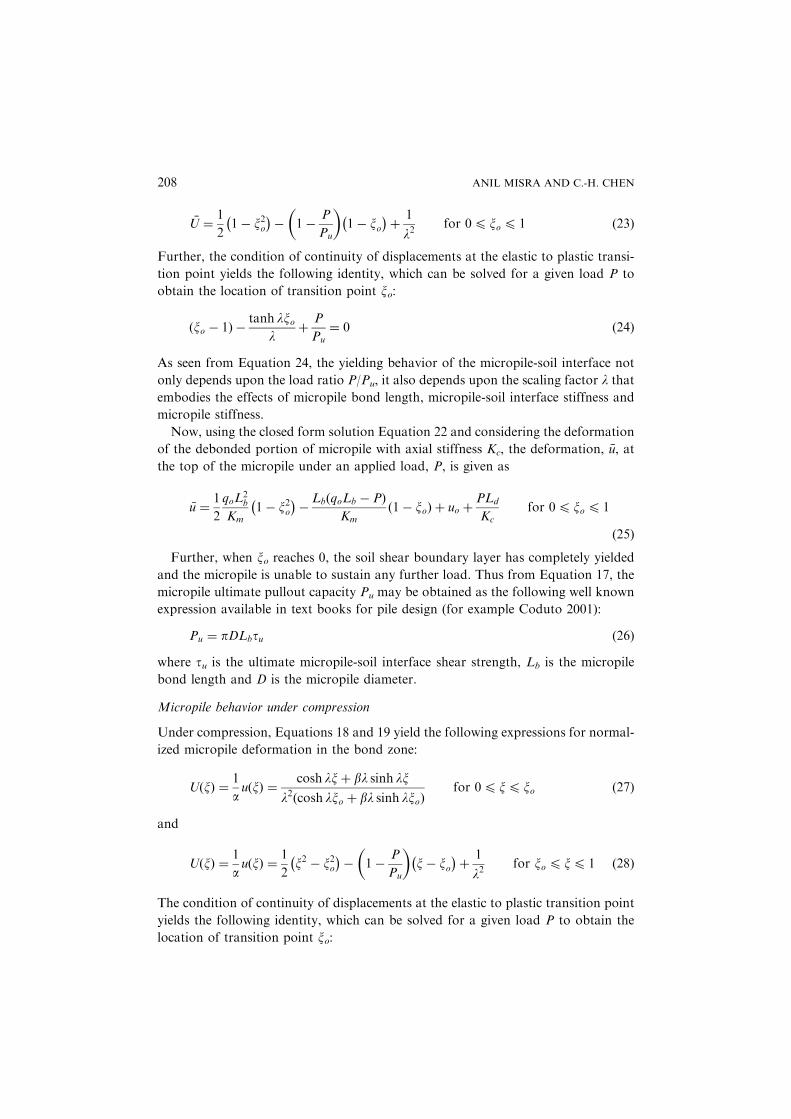
than expected. Based upon measured pullout load-displacement curves available in
the literature, the micropile-soil interface shear strength, tu, were calculated for a
variety of micropiles (Taylor et al. 1998, Zelenko et al. 1998, Misra et al. 1999,
Nakata and Kishishita 1999). The calculated interface shear strength, tu, is given
in Figure 6 for various grout or post grout pressures in different soil conditions.
For clays or silty clay soils, the interface shear strength range from a low of 170
to a high of 460 kN/m2 depending upon the grout pressures and the number of post
grouts. For a site with sandy to silty clays and weathered limestone, the interface
shear strength was obtained to be 245 kN/m2 at a grout pressure of 690 kN/m2
and for a site with highly consolidated hardpan the interface shear strength was
found to vary from 630 to 920 kN/m2 under gravitational grouting conditions. It
is interesting to note that the interface shear strength values are generally higher than
that observed by Ostermayer (1974) for clay soils in the context of ground anchors.
Figure 5 Example of measured and predicted load-displacement curve
210 ANIL MISRA AND C.-H. CHEN
Closed form expressions for initial stiffness dP/dumay be obtained fromEquation 9
or Equation 14 for micropiles under pullout and compression, respectively. The
initial stiffness is related to the non-dimensional factor, b, scaling factor, l, micropile
bond length, Lb, micropile axial stiffness in bond zone, Km, and micropile axial stiff-
ness in debond zone, Kc. The micropile axial stiffness in the bond zone, Km, may be
obtained as the sum of the axial stiffness of the micropile reinforcement and the axial
stiffness of the surrounding grout, given as AsEsþAgEg. Where As and Ag are the
cross-section area, and Es andEg are the Young’s modulus of the micropile reinfor-
cement and surrounding grout, respectively. The reinforcing bars used in micropiles
are, often, large diameter bars. For example, in the United States either a #18 rebar
of cross-section area �25.8 cm2 or, in limited cases, a #20 bar of cross-section area
�31.6 cm2 is used, while in Japan SD490, D51 bar of cross-section area �20.3 cm2 is
used. The typical cement grout used in micropiles has a modulus of �2104 N/mm2.
For a 200-mm diameter micropile reinforced with Japanese SD490, D51 rebar, the
micropile axial stiffness, Km, is found to be �1103 MN. Similarly, the micropile
axial stiffness in the debond zone, Kc, may be obtained as sum of the axial stiffnesses
of the micropile casing, the rebar and the grout. Thus, the non-dimensional factor, b,scaling factor, l, and consequently, the shear modulus of the micropile-soil interface,
K may be obtained from measured load-displacement curves for a given micro-
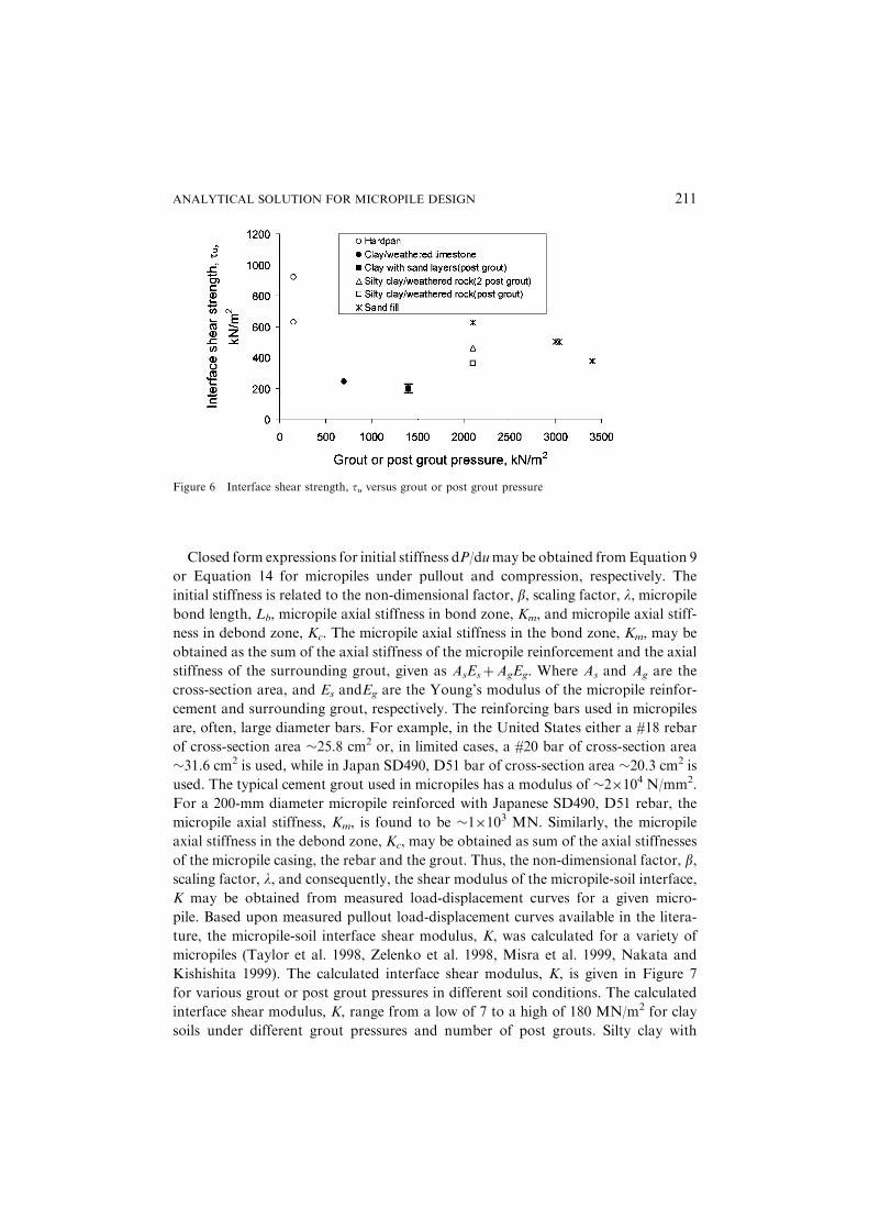
pile. Based upon measured pullout load-displacement curves available in the litera-
ture, the micropile-soil interface shear modulus, K, was calculated for a variety of
micropiles (Taylor et al. 1998, Zelenko et al. 1998, Misra et al. 1999, Nakata and
Kishishita 1999). The calculated interface shear modulus, K, is given in Figure 7
for various grout or post grout pressures in different soil conditions. The calculated
interface shear modulus, K, range from a low of 7 to a high of 180 MN/m2 for clay
soils under different grout pressures and number of post grouts. Silty clay with
Figure 6 Interface shear strength, tu versus grout or post grout pressure
ANALYTICAL SOLUTION FOR MICROPILE DESIGN 211

weathered rock yields a lower shear modulus even under a higher grout pressure in
contrast to the case of clay soils with interspersed sand layers.
The micropile-soil interface shear strength and modulus are significantly influ-
enced by the complex interaction between the in-situ soils and the grout placed dur-
ing installation. The in-situ soil properties, such as soil composition, water content,
saturation, stiffness and strength, and the grout properties, such as grout composi-
tion, viscosity, pressure, stiffness and strength, all affect the properties of micro-
pile-soil interface. Figure 8 shows the micropile-soil interface properties obtained
from the analysis of two-cases with predominantly clay soils. In the case of silty clay
with weathered rock a grout pressure of 2100 kN/m2 was used, while in the case of
clay with thin sand layers a grout pressure of 1400 kN/m2 was used. In the first case,
Figure 7 Interface shear modulus, K, versus grout or post grout pressure
Figure 8 Micropile-soil interface behavior for two cases
212 ANIL MISRA AND C.-H. CHEN

a low stiffness-high strength interface is obtained, while in the second case a high
stiffness-low strength interface is obtained. Clearly, this difference in the behavior
of similar soils results from the interaction of the in-situ soil and the pressurized
grout. Further analysis considering various soil conditions and grouts may be needed
to definitively characterize the micropile-soil interface behavior. However, given the
paucity of data in the published literature, such analysis is outside the scope of this
paper.
4.2. INFLUENCE OF MODEL PARAMETERS AND SCALING FACTORS
The scaling factor, l, and the non-dimensional factor, b, profoundly influence the
micropile behavior. The scaling factor, l, may be interpreted as the ratio between
micropile-soil interface shear stiffness, KLb, and micropile axial stiffness per unit
length, Km/Lb. Considering that micropile bond length, Lb, may range from 3m to
20m, and that the ratios of interface shear modulus and micropile axial stiffness,
K/Km, may vary from 10�1 m�2 to 1 m�2, the scaling factor, l, would take a value
from a low of 1 to a high of 20. The non-dimensional factor, b, gives the ratio of
micropile tip soil stiffness, Ks, and micropile-soil interface shear stiffness, KLb. Elas-
ticity theories of a punch bearing upon elastic half-space indicate that the micropile
tip soil stiffness would be proportional to soil modulus of elasticity and tip-diameter
(see Equation 11). Therefore, the significant factors that control non-dimensional
factor, b, are the ratio of micropile diameter and bond length, D/Lb, and the ratio
of soil modulus of elasticity and the shear modulus of micropile-soil interface,
Es/K. Considering that D/Lb ranges from 10�2 to 310�2 and Es/K ranges from
210�2 to 8, the non-dimensional factor, b, would typically range from 10�4 to 10�1.
Figure 9 examines the influence of scaling factor, l, and non-dimensional factor, b,upon the progress of plastic zone located by plastic transition point, xo, with load
ratio. The load ratio is the applied load, P, expressed as a ratio of the ultimate pullout
Figure 9 Progress of interface yield with micropile loading
ANALYTICAL SOLUTION FOR MICROPILE DESIGN 213

load. It is seen from Figure 9, that under pullout for l¼1 (b¼0), the location of the
plastic transition point is the top of micropile (xo¼1) for load ratios up to 0.8. In
other words, the soil shear boundary layer remains elastic for applied loads up to
80% of the ultimate pullout capacity. The soil shear boundary layer yields at 30%
of the ultimate pullout capacity when l¼ 3 (b¼ 0). In comparison, under compres-
sion with a relatively stiff tip soil, such that l¼ 1 and b¼ 0.1, the onset of yield is
delayed. Interestingly, under compression, the interface completely yields at a load
ratio of 1þb (Note that the load ratio 1 represents the pullout capacity). Thus under
compression, the micropile will exhibit yield behavior at 1þ b times the pullout
capacity.
The micropile behavior under pullout and compression is further examined in
Figure 10, which gives a plot of load ratio versus non-dimensional micropile displa-
cement u(x). Figure 10 is obtained from Equation 23, using Equation 24 to calculate
the plastic transition point xo for the case of pullout (b¼ 0) and Equation 29 for the
case of compression behavior (b¼ 0.1), respectively. It is observed that the initial
load-displacement behavior of the micropile is profoundly influenced by the scaling
factor, l, which effects the yield behavior of micropile-soil interface. For soft micro-
pile-soil interface, that is, K/Km 10�1m�2 and large bond length Lb¼10m, such
that l¼3, the load-displacement behavior is considerably stiffer than that for l¼1,
with similar K/Km but a shorter bond length Lb¼ 3m. However, for values of
l>3, the micropile load-displacement curves are grouped in a narrow zone, indicat-
ing that for a given micropile-soil interface stiffness and micropile axial stiffness, any
further increase in bond-length will only marginally alter the initial load-
displacement behavior. Furthermore, it is observed that the compression load-
displacement curve is only marginally stiffer than the pullout curve, which confirms
that micropiles primarily carry load via side resistance. In addition, the micropile
exhibits yielding at 1þb times the pullout capacity. The yield point may be clearly
seen for micropiles with l4 3. For micropiles with relatively long bond length, such
that l> 3, and stiff tip soil, such that b> 0.1 the rate of post yield deformation is
Figure 10 Influence of scaling factors l and b upon the micropile load-displacement behavior
214 ANIL MISRA AND C.-H. CHEN
relatively small. In these cases, the yield point is not clearly seen from the load-
displacement curve.
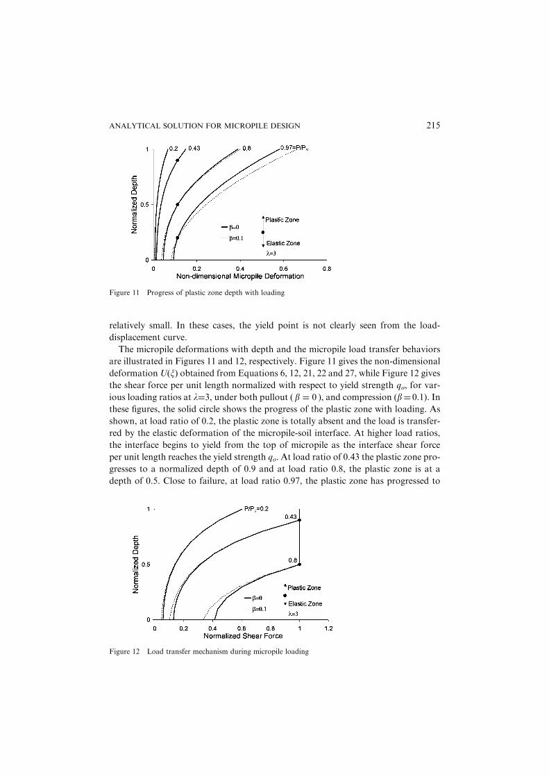
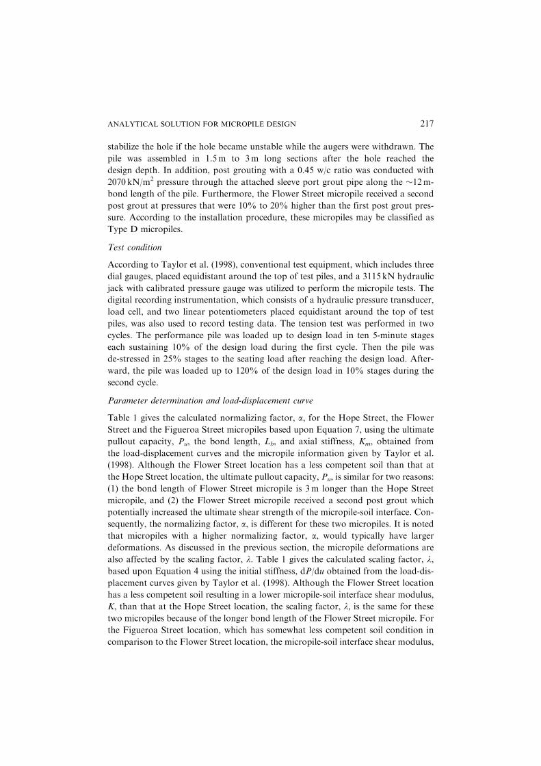
The micropile deformations with depth and the micropile load transfer behaviors
are illustrated in Figures 11 and 12, respectively. Figure 11 gives the non-dimensional
deformation U(x) obtained from Equations 6, 12, 21, 22 and 27, while Figure 12 gives
the shear force per unit length normalized with respect to yield strength qo, for var-
ious loading ratios at l¼3, under both pullout ð b ¼ 0 Þ, and compression (b¼ 0.1). In
these figures, the solid circle shows the progress of the plastic zone with loading. As
shown, at load ratio of 0.2, the plastic zone is totally absent and the load is transfer-
red by the elastic deformation of the micropile-soil interface. At higher load ratios,
the interface begins to yield from the top of micropile as the interface shear force
per unit length reaches the yield strength qo. At load ratio of 0.43 the plastic zone pro-
gresses to a normalized depth of 0.9 and at load ratio 0.8, the plastic zone is at a
depth of 0.5. Close to failure, at load ratio 0.97, the plastic zone has progressed to
Figure 11 Progress of plastic zone depth with loading
Figure 12 Load transfer mechanism during micropile loading
ANALYTICAL SOLUTION FOR MICROPILE DESIGN 215

a normalized depth of 0.2. We also observe from Figure 11 that the micropile defor-
mation in the plastic zone is greater under compression than under pullout. Conse-
quently, the micropile transmits a smaller load to the micropile-soil interface in the
elastic zone under compression than under pullout as borne out by the smaller shear
force per unit length in the elastic zone in Figure 12 under compression.
5. Measured and Calculated Micropile Behavior
The load-displacement curves obtained from the derived model are compared with
field measured load-displacement curves available in the literature. Two different
case histories of measured load-displacement behavior of micropiles are used in this
comparison.
5.1. CASE HISTORY 1—PULLOUT BEHAVIOR
Site condition
Taylor et al. (1998) presented case histories of measured pullout behavior of pre-pro-
duction micropiles designed for seismic retrofits in Los Angeles, California. These
micropiles were located near the Fourth Street Viaduct, on Hope, Flower, and
Figueroa streets. The micropiles were used to retrofit the bridge foundations at
the Fourth Street Viaduct. The site geology at the Fourth Street Viaduct consists
of mixed alluvium, fill and bedrock. Alluvium and fill consists of moist to wet silty
clay or clayey silt (CL-ML), some clayey sand (SC) and small amounts of gravelly
sand (SP). The bedrock is part of the Puente formation and is described as poor
to moderately hard moist/wet mudstone. The bedrock closer to the surface
was highly weathered and very similar to the overlying alluvium and exhibited the
characteristics of hard clay. All the micropiles are bonded in the soil layers and do
not extend to the competent bedrock. The ultimate shear strength tested from
laboratory samples indicates 35� 103 kN/m2 for alluvium and 240� 515 kN/m2
for bedrock. Furthermore, it was noted that the Hope Street micropile location
had the most competent soil layer, while the Flower and Figueroa Street micropile
locations had less competent soil layers that were soft and saturated from 1.5m to
15m depth.
Installation method
The pile casing used for the micropiles had an outside diameter (O.D.) of 0.178m
and a thickness of 1 cm. Taylor et al. (1998) do not give the rebar size used for
the micropile. For the calculations we assume the rebar to be #18 of area
25.8 cm2. Micropiles located in the viaduct were auger drilled with 13.6 kN/m torque
in cohesive or cemented soil up to full drill depth of 18m. The Hope Street micropile
had a total length of 18m with 12m bond length, the Flower micropile had a total
length of 18m with 15m bond length and the Figueroa Street micropile had a total
length of 15m with 12m bond length. High strength neat-cement grout was used to
216 ANIL MISRA AND C.-H. CHEN
stabilize the hole if the hole became unstable while the augers were withdrawn. The
pile was assembled in 1.5m to 3m long sections after the hole reached the
design depth. In addition, post grouting with a 0.45 w/c ratio was conducted with
2070 kN/m2 pressure through the attached sleeve port grout pipe along the �12m-
bond length of the pile. Furthermore, the Flower Street micropile received a second
post grout at pressures that were 10% to 20% higher than the first post grout pres-
sure. According to the installation procedure, these micropiles may be classified as
Type D micropiles.
Test condition
According to Taylor et al. (1998), conventional test equipment, which includes three
dial gauges, placed equidistant around the top of test piles, and a 3115 kN hydraulic
jack with calibrated pressure gauge was utilized to perform the micropile tests. The
digital recording instrumentation, which consists of a hydraulic pressure transducer,
load cell, and two linear potentiometers placed equidistant around the top of test
piles, was also used to record testing data. The tension test was performed in two
cycles. The performance pile was loaded up to design load in ten 5-minute stages
each sustaining 10% of the design load during the first cycle. Then the pile was
de-stressed in 25% stages to the seating load after reaching the design load. After-
ward, the pile was loaded up to 120% of the design load in 10% stages during the
second cycle.
Parameter determination and load-displacement curve
Table 1 gives the calculated normalizing factor, a, for the Hope Street, the Flower
Street and the Figueroa Street micropiles based upon Equation 7, using the ultimate
pullout capacity, Pu, the bond length, Lb, and axial stiffness, Km, obtained from
the load-displacement curves and the micropile information given by Taylor et al.
(1998). Although the Flower Street location has a less competent soil than that at
the Hope Street location, the ultimate pullout capacity, Pu, is similar for two reasons:
(1) the bond length of Flower Street micropile is 3m longer than the Hope Street
micropile, and (2) the Flower Street micropile received a second post grout which
potentially increased the ultimate shear strength of the micropile-soil interface. Con-
sequently, the normalizing factor, a, is different for these two micropiles. It is noted
that micropiles with a higher normalizing factor, a, would typically have larger
deformations. As discussed in the previous section, the micropile deformations are
also affected by the scaling factor, l. Table 1 gives the calculated scaling factor, l,based upon Equation 4 using the initial stiffness, dP/du obtained from the load-dis-
placement curves given by Taylor et al. (1998). Although the Flower Street location
has a less competent soil resulting in a lower micropile-soil interface shear modulus,
K, than that at the Hope Street location, the scaling factor, l, is the same for these
two micropiles because of the longer bond length of the Flower Street micropile. For
the Figueroa Street location, which has somewhat less competent soil condition in
comparison to the Flower Street location, the micropile-soil interface shear modulus,
ANALYTICAL SOLUTION FOR MICROPILE DESIGN 217
K, was smaller. Moreover, as the Figueroa Street micropile has a smaller bond length
than the Flower Street micropile, both the normalizing factor, a, and the scaling fac-
tor, l, are calculated to be lower. The back calculated average shear modulus of the
micropile-soil interface for these micropiles vary from �26MN/m2 to �59MN/m2.
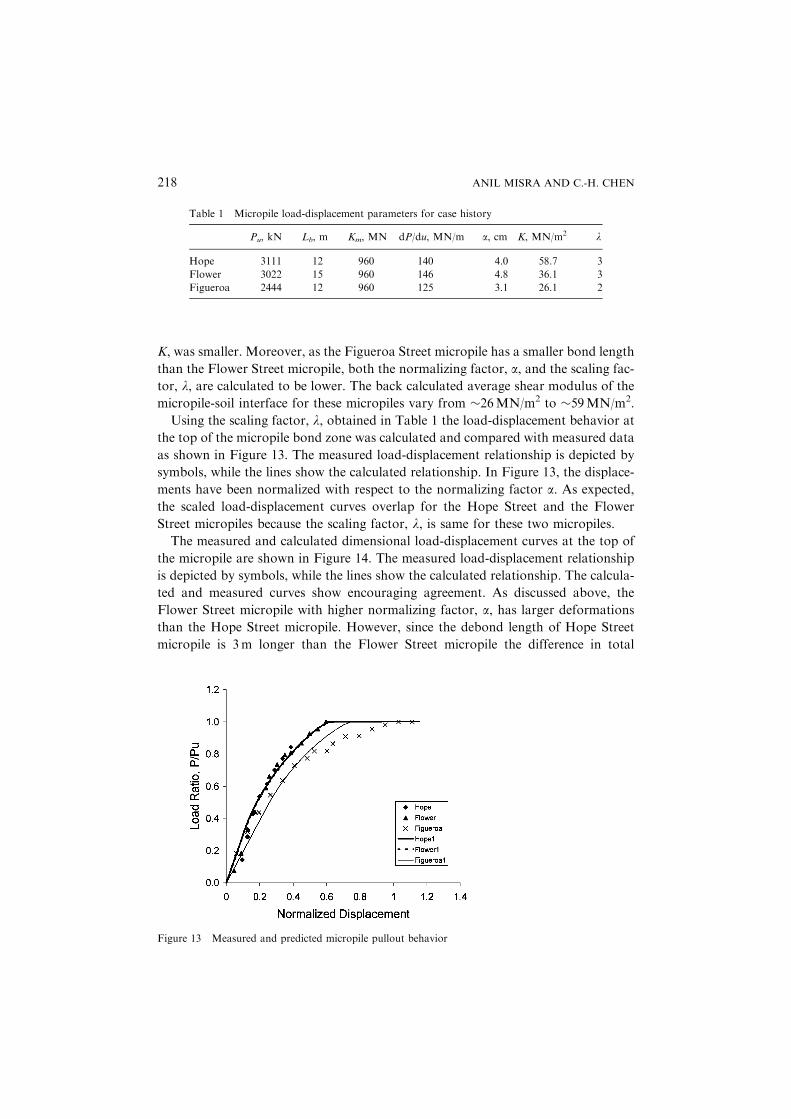
Using the scaling factor, l, obtained in Table 1 the load-displacement behavior at
the top of the micropile bond zone was calculated and compared with measured data
as shown in Figure 13. The measured load-displacement relationship is depicted by
symbols, while the lines show the calculated relationship. In Figure 13, the displace-
ments have been normalized with respect to the normalizing factor a. As expected,
the scaled load-displacement curves overlap for the Hope Street and the Flower
Street micropiles because the scaling factor, l, is same for these two micropiles.
The measured and calculated dimensional load-displacement curves at the top of
the micropile are shown in Figure 14. The measured load-displacement relationship
is depicted by symbols, while the lines show the calculated relationship. The calcula-
ted and measured curves show encouraging agreement. As discussed above, the
Flower Street micropile with higher normalizing factor, a, has larger deformations
than the Hope Street micropile. However, since the debond length of Hope Street
micropile is 3m longer than the Flower Street micropile the difference in total
Table 1 Micropile load-displacement parameters for case history
Pu, kN Lb, m Km, MN dP/du, MN/m a, cm K, MN/m2 l
Hope 3111 12 960 140 4.0 58.7 3
Flower 3022 15 960 146 4.8 36.1 3
Figueroa 2444 12 960 125 3.1 26.1 2
Figure 13 Measured and predicted micropile pullout behavior
218 ANIL MISRA AND C.-H. CHEN
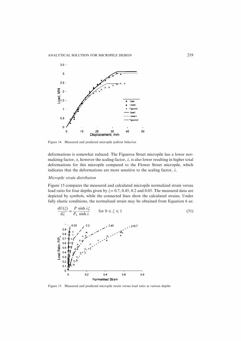
deformations is somewhat reduced. The Figueroa Street micropile has a lower nor-
malizing factor, a, however the scaling factor, l, is also lower resulting in higher total
deformations for this micropile compared to the Flower Street micropile, which
indicates that the deformations are more sensitive to the scaling factor, l.
Micropile strain distribution
Figure 15 compares the measured and calculated micropile normalized strain versus
load ratio for four depths given by x¼ 0.7, 0.45, 0.2 and 0.03. The measured data are
depicted by symbols, while the connected lines show the calculated strains. Under
fully elastic conditions, the normalized strain may be obtained from Equation 6 as:
dUðxÞdx
¼P
Pu
sinh lxsinh l
for 04x4 1 ð31Þ
Figure 14 Measured and predicted micropile pullout behavior
Figure 15 Measured and predicted micropile strain versus load ratio at various depths
ANALYTICAL SOLUTION FOR MICROPILE DESIGN 219

Under elasto-plastic conditions, the normalized strains are obtained from Equations
21 and 22 as
dUðxÞdx
¼sinh lx
l cosh lxo
for 04x4xo ð32Þ
and
dUðxÞdx
¼ x� 1ð Þ þP
Pufor xo 4x4 1 ð33Þ
It is encouraging that the model derived in this paper replicates both the measured
load-displacement relationship and the strain distribution fairly closely.
5.2. CASE HISTORY 2—COMPRESSION BEHAVIOR
Site condition
Nakata and Kishishita (1999) have presented case histories of measured compression
behavior of micropiles tested under the auspices of the Japanese Association of
Micropiles. The test site consists of 11.8m thick soft silt layer overlying a highly con-
solidated hardpan layer. The micropile is anchored in the hardpan layer. The refer-
ence does not have a detailed description of soil properties.
Installation method
The casing used for the micropiles has an outside diameter (O.D.) of 0.178m and a
thickness of 12.7mm. The rebar size used was SD490, D51 with a cross-section area
of 20.3 cm2. Micropiles were drilled to a full drill depth of �18m. The casing was
installed through the soft silt layer and 1.5m into the hardpan layer to a depth of
�13m. The bond zone had a diameter of 0.2m and a bond length of 6m. Grout with
a compressive strength of >35N/mm2 and 0.45w/c ratio was injected into the micro-
pile. Due to insufficient information regarding grout pressures used in this case, we
assume the micropiles to be of Type B.
Test condition
The dial gauges and 300-ton jacks were placed equidistant around the top of test
piles to perform the compression loading test. In addition, strain gauges were
attached around the casing and rebar to measure strain distribution at various
depths. The maximum load applied for the compression loading test was 3600 kN
with six loading cycles.
Parameter determination and load-displacement curve
Figure 16 gives the measured and calculated load-displacement curves for the micro-
pile. The micropile displacements were measured at both the top and tip of the
micropile. The measured load-displacement relationships are depicted by symbols,
while the lines show the calculated relationships. Encouragingly close agreement is
220 ANIL MISRA AND C.-H. CHEN
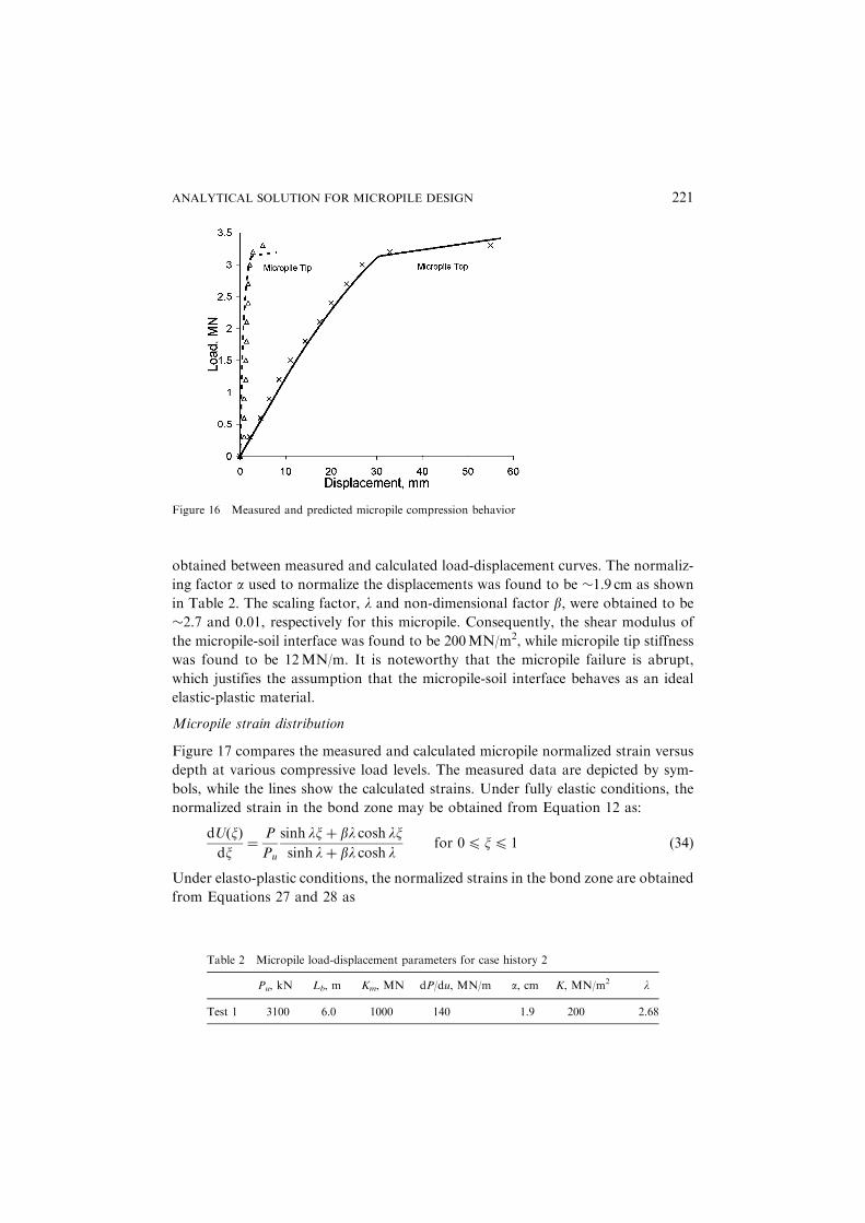
obtained between measured and calculated load-displacement curves. The normaliz-
ing factor a used to normalize the displacements was found to be �1.9 cm as shown
in Table 2. The scaling factor, l and non-dimensional factor b, were obtained to be
�2.7 and 0.01, respectively for this micropile. Consequently, the shear modulus of
the micropile-soil interface was found to be 200MN/m2, while micropile tip stiffness
was found to be 12MN/m. It is noteworthy that the micropile failure is abrupt,
which justifies the assumption that the micropile-soil interface behaves as an ideal
elastic-plastic material.
Micropile strain distribution
Figure 17 compares the measured and calculated micropile normalized strain versus
depth at various compressive load levels. The measured data are depicted by sym-
bols, while the lines show the calculated strains. Under fully elastic conditions, the
normalized strain in the bond zone may be obtained from Equation 12 as:
dUðxÞdx
¼P
Pu
sinh lxþ bl cosh lxsinh lþ bl cosh l
for 04x4 1 ð34Þ
Under elasto-plastic conditions, the normalized strains in the bond zone are obtained
from Equations 27 and 28 as
Figure 16 Measured and predicted micropile compression behavior
Table 2 Micropile load-displacement parameters for case history 2
Pu, kN Lb, m Km, MN dP/du, MN/m a, cm K, MN/m2 l
Test 1 3100 6.0 1000 140 1.9 200 2.68
ANALYTICAL SOLUTION FOR MICROPILE DESIGN 221

dUðxÞdx
¼sinh lxþ bl cosh lx
l cosh lxo þ bl sinh lxoð Þfor 04x4xo ð35Þ
and
dUðxÞdx
¼ x� 1ð Þ þP
Pufor xo 4x4 1 ð36Þ
where the transition point xo is obtained from Equation 29. The normalized strains
in the debonded zone are obtained as a constant
dUðxÞdx
¼P
Pu
Km
Kcfor x > 1 ð37Þ
The model calculations replicate the strain distribution fairly closely in both the
bond and debonded zones. Interestingly, for this micropile, the strains were mea-
sured in both the bond zone, given by the normalized depth 04x4 1, and the
debonded zone, given by normalized depth x> 1. From Figure 17, we observe that
the measured micropile strain is almost constant in the debonded zone. This indi-
cates that the micropile transmits very little load over the debonded zone and justi-
fies the model assumption of partially bonded micropiles.
6. Summary and Conclusions
A mathematical model is presented for micropile load-displacement behavior under
pullout and compression. The micropile-soil interaction is explicitly considered in the
model development. Based upon field measurements, it is assumed that the micropile
is partially bonded, consisting of a top debonded zone and a bottom bond zone.
Consequently, the micropile is assumed to transmit its load to the surrounding soil
through the micropile-soil interface in the bond zone only. Furthermore, to ensure
model simplicity and accessibility to designers, the micropile-soil interface is assumed
to be elastic-perfectly plastic characterized by the shear modulus of the micropile-soil
interface K, and the ultimate micropile-soil interface shear strength tu. Additionally,
with the aim of obtaining closed form expressions for micropile load-displacement
relationship, the following simplifying assumptions are made:
Figure 17 Measured and predicted micropile strain versus depth at loading level
222 ANIL MISRA AND C.-H. CHEN

(1) The bond length is composed of micropile reinforcement surrounded by grout
and the debonded length is composed of micropile casing filled with reinforce-
ment and grout.
(2) The micropile-soil interface in the bond zone is homogeneous, such that the
effects of soil layers and any inhomogeneity in grouting are smeared. We note
that the interface reflects the properties of the soil-grout shear-boundary layer,
which, in general, are not directly related to the soil properties, but also depend
upon the grout properties, grout pressure and construction techniques, and may
not necessarily follow the stratification of the natural soil.
Given the above simplifying assumptions, the model performs encouragingly well in
replicating the measured load-displacement behavior as well as the load transmission
behavior of micropiles.
Closed form expressions for micropile load-displacement relationship are obtained
for pullout and compressive loading under both elastic and elasto-plastic deforma-
tion of micropile-soil interface. It is found that the model parameters determining
the load-displacement behavior may be classified into two sets:
(1) The micropile-soil interface properties consisting of the ultimate shear strength
of micropile-soil interface, tu, the shear modulus of micropile-soil interface, K,
and the tip soil stiffness Ks, and
(2) The micropile properties include micropile diameter, D, bond length, Lb, debond
length, Ld, micropile axial stiffness in the bond zone, Km, and micropile axial
stiffness in the debond zone, Kc.
The model parameters may be combined into scaling factors a¼PuLb/Km, b¼Ks/KLb, and l¼
ffiffiffiffiffiffiffiffiffiffiffiffiffiffiffiffiffiffiKL2
b=Km
q, which signify the relative influences of model parameters
on micropile behavior:
(1) The normalized factor a embodies the relative effects of micropile-soil interface
shear strength, micropile axial stiffness and micropile size. The derived expres-
sions Equations 22 and 28 show that the minimum displacement at the top of
bond zone of a micropile is a/2. The closed form expressions for micropile
load-displacement relationship may be non-dimensionalized using the normal-
ized factor a. Thus, universal normalized load-displacement curves may be devel-
oped for a given site and installation procedure.
(2) The non-dimensional factor b gives the relative importance of micropile tip soil
stiffness while the scaling factor l embodies the influence of micropile-soil inter-
face shear modulus. Parametric studies of load-displacement relationship show
that the scaling factors l and b, influence the stiffness, ultimate capacity and
the yield behavior of micropiles as follows:
(i) The scaling factor l primarily influences the initial stiffness of the load-
displacement curve and failure displacement of the micropile. It is
ANALYTICAL SOLUTION FOR MICROPILE DESIGN 223

observed that for l> 3, the load-displacement curves are grouped in a
narrow zone, indicating that a for a given soil and micropile diameter,
any further increase in bond-length will only marginally increase the
micropile stiffness.
(ii) It is observed that the scaling factors l and b affect the micropile-soil
yield behavior. For l¼ 1, the soil shear boundary layer remains elastic
for applied loads up to 80% of the ultimate pullout capacity, while for
l¼3, the soil shear boundary layer yields at 30% of the ultimate pullout
capacity. The relative effect of b is higher when l¼ 1, and the effect
diminishes as l increases.
(iii) The non-dimensional factor b affects the proportion of load transmitted
through the micropile tip. As a result, the scaling factor b delays the onset
of yield and influences the micropile ultimate compression capacity. Para-
metric study show that micropiles primarily carry load via side resistance.
The measured micropile load-displacement data available in the literature are ana-
lyzed to evaluate the model parameters and scaling factors. It is found that the
micropile-soil interface shear strength, tu, and shear modulus, K, are significantly
influenced by the soil properties, the grout properties and the construction technique,
as well as the complex interaction between the in-situ soils and the grout placed dur-
ing installation. Two case studies are presented to demonstrate the model capability.
Micropile strain distribution and the consequent stress transfer behavior predicted
by the model are compared with measured data. The model calculations are also
compared with the field measured load-displacement curves. The model performs
encouragingly well in replicating the measured load-displacement behavior as well
as the load transmission behavior of micropiles.
References
Baguelin F., Frank R. and Jezequel J. F. (1982) Parameters for friction piles in marine soils,
In: Proceedings 2nd Int. Conf. Num. Meth. In Offshore Piling, Austin, Texas. April,pp. 197–214.
Bruce, D. A., Bruce, M. E. C. and Traylor, R. P. (1999). High capacity micropiles – Basic prin-
ciples and case histories, in Geo-Engineering for Underground Facilities, GeotechnicalSpecial Publication No. 90, (edited by G. Fernandez and R.A. Bauer). ASCE, Reston,Virginia. pp. 188–199.
Coduto, D. P. (2001). Foundation Design: Principles and Practices. Prentice-Hall, New Jersey.FHWA (1993). Recommendations Clouterre 1991, in Report No. FHWA-SA-93–026 Chapter
4 Appendix, Federal Highway Administration, U.S. Department of Transportation,McLean, Virginia. pp. 193–202.
FHWA (1997). Drilled and Grouted Micropiles: State-of-Practice Review Volume I-IV, inReport No. FHWA-RD-96–016, 017, 018, 019, Federal Highway Administration, U.S.Department of Transportation, McLean, Virginia.
FHWA (2000). Micropile Design and Construction Guidelines – Implementation Manual, inReport No. FHWA-SA-97–070, Federal Highway Administration, U.S. Department ofTransportation, McLean, Virginia.
224 ANIL MISRA AND C.-H. CHEN
IWM99 (1999). Proceedings of Second International Workshop on Micropiles, Yamaguchi
University, Ube City, Japan.Johnson, K. L. (1985). Contact Mechanics. Cambridge University Press, London, UK.Juran, I. and Christopher, B. (1989). Laboratory model study on geosynthetic reinforced soil
retaining walls, In: Journal of Geotechnical Engineering, ASCE, Vol. 115, No. 7, pp.905–926.
Kraft, L. M., Ray, R. M. and Kagawa, T. (1981). Theoretical t-z curves, In: Journal of Geo-
technical Engineering, ASCE, Vol. 107, No. 11, pp. 1543–1561.Laefer, D. F. (1999). Geotechnical procedures for at-risk and in-distress structures, In: L. B.
Sickels-Taves (eds.). The Use of and Need for Preservation Standards in Architectural Con-servation, ASTM STP 1355, ASTM, West Conshohocken, PA. pp. 211–225.
Mascardi, C. A. (1982). Design criteria and performance of micropiles, In: Recent Develop-ments in Ground Improvement Techniques, A. A. Balkema, Rotterdam. pp. 439–450.
Misra, A. and Chen, C.-H. (2002). Load displacement relationships for micropiles, In: M. W.
O’Neill and F. C. Townsend (eds.). Deep Foundations 2002: An International Perspectiveon Theory, Design, Construction, and Performance, Geotechnical Special Publication No.116, ASCE, New York. pp. 110–125.
Misra, A., Oberoi, R. and Kleiber, A. (1999). Micropiles for Seismic Retrofitting of HighwayInterchange Foundation, In: IWM99, Proceedings of Second International Workshop onMicropiles, Yamaguchi University, Ube City, Japan. pp. 215–223.
Nakata, Y. and Kishishita, T. (1999). Experimental Study for Behavior of Micropile
Foundation, In: IWM99, Proceedings of Second International Workshop on Micropiles,Yamaguchi University, Ube City, Japan. pp. 189–194.
Ostermayer, M. (1974). Construction, carrying behavior and creep characteristics of ground
anchors, In: Conference on Diaphragm Walls and Anchorages, Institute of Civil Engineers,London, U.K.
Reese, L. C. and O’Neill, M. W. (1987). Drilled Shafts: Construction Procedures and Design
Methods, In: Report No. FHWA-HI-88–042, Federal Highway Administration, U.S.Department of Transportation, McLean, Virginia.
Schaefer, V. R. et al. (Eds.) (1997). Ground Improvement Ground Reinforcement Ground
Treatment, In: Geotechnical Special Publication No. 69, ASCE, New York. pp. 151–17.Scott, R. F. (1981). Foundation Analysis. Prentice-Hall, New Jersey.Taylor, G. E., Gularte, F. B., and Gularte, G. G. (1998). Seismic retrofit of Fourth Street &
Riverside viaducts with micropiles, In: A. Maher and D. S. Yang (eds.). Soil Improve-
ment for Big Digs, Geotechnical Special Publication No. 81, ASCE, Reston, Virginia.pp. 313–325.
Zelenko, B. H., Bruce, D. A., Schoenwolf, D. A. and Traylor, R. P. (1998). Micropile appli-
cations for seismic retrofit preserves historic structure in old San Juan, Puerto Rico, In:L. Johnsen and D. Berry (eds.). Grouts and Grouting, Geotechnical Special PublicationNo. 80, ASCE, Reston, Virginia. pp. 43–62.
ANALYTICAL SOLUTION FOR MICROPILE DESIGN 225