analyzing miniature electrodynamic tether propulsion capabilities...
TRANSCRIPT

187
1
Analyzing Miniature Electrodynamic Tether Propulsion Capabilities and the Interaction with the
Low Earth Orbit–Plasma Environment
Abstract— The sub-kilogram, “smartphone”-sized satellite is
the next frontier in satellite miniaturization. Previous studies have shown that short (few meters), electrodynamic tethers can provide 10-g to 1-kg satellites with complete drag cancellation and the ability to change orbit. The miniaturized ED tethers considered here connect a pair of nearly identical pico- or femtosatellites that work together as a unit. Electron emitting and collecting plasma contactors are critical components of this propulsion concept because they close the tether circuit in the ambient plasma, allowing conduction of current in the tether and generation of thrust. One approach for electron collection is to collect current on the positively biased surface of one of the satellites in the tethered pair. This paper presents progress made on ground-based plasma experiments that capture key characteristics of the low Earth orbit (LEO)–tether system interaction, like the current collector’s geometry and the ratio of the Debye length to the collector’s characteristic dimensions. This paper describes the characterization of the laboratory plasma, compares the environment with LEO, and presents the current–voltage (I–V) characteristics of planar and cubic probes in the plasma, each probe approximating a small satellite in LEO. The tests showed that the current for planar and cubic probes increased nearly linearly with voltage at large potentials relative to the local plasma potential. The planar and cubic probes also collected less current on a per-area basis than a similarly-sized sphere. In the voltage range tested, theory used in previous trade-studies to predict the collection current provides a rough, order-of-magnitude estimate. The paper also describes an in-space experiment that will demonstrate miniature tether technology (MiTEE-Miniature Tether Electrodynamic Experiment).
Keywords—Electrodynamic tether; anode; electron sheath; current collection; picosatellite; femtosatellite.
I. INTRODUCTION A new class of small, sub-kilogram, “smartphone”-sized
satellites are emerging as the next frontier of miniaturized satellites. The concept represents an evolution beyond the nanosatellite (1–10 kg) platform, made possible because of advances in electronics miniaturization and power reduction. These spacecrafts, known as picosatellites (100 g–1 kg) and femtosatellites (<100 g), have longest dimensions that range from about ten centimeters down to a few centimeters in length [1]–[4]. Due to their small size and mass, pico- and femtosatellites show potential to be dramatically less expensive (on a per unit basis) to boost into orbit. As a result, it may be possible to launch large numbers of these satellites, unlocking the potential for low cost constellations.
The potential to deploy large numbers of pico- and femtosats in a controlled, coordinated formation suggests that propulsion and maneuverability would significantly enable the concept. Propulsion is also important because these small satellites will likely have high area-to-mass ratios, causing short orbital lifetimes. Previous trade studies have shown that a short (few meters) electrodynamic tether shows potential to provide propellantless propulsion for pico- and femtosatellites [5]. Fig. 1 shows an illustration of the concept, where pairs of femtosatellites are connected by short, semi-rigid ED tethers. To generate current flow in the tether, the system concept emits electrons from one of the tethered satellites and collects electrons from the ionosphere on the positively-biased, exposed conducting surfaces of the opposite satellites. Thrust estimates were based on a set of simplifying assumptions made to facilitate estimating the current collection. In this paper, we revisit these assumptions and describe a ground-based laboratory experiment in which we simulate characteristics of the orbital environment in order to refine previous estimates. We also discuss the Miniature Tether Electrodynamics Experiment (MiTEE) mission being planned to demonstrate the miniature tether concept.
II. BACKGROUND
A. Electrodynamic Tether Background An electrodynamic (ED) tether is a conducting wire
connecting a pair of satellites. ED tethers are used in the ionosphere, which is a plasma. If both ends of the tether are able to exchange charge with the plasma, the ionosphere can provide a path to “complete the circuit,” enabling current flow
Iverson C. Bell, III, Brian E. Gilchrist, Jesse K. McTernan, Sven G. Bilén
I. Bell is with the Radiation Laboratory, Department of Electrical Engineering and Computer Science, University of Michigan, Ann Arbor, 48109, USA (e-mail: [email protected])
B. Gilchrist is with the Radiation Laboratory, Department of Electrical Engineering and Computer Science and the Department of Atmospheric, Oceanic and Space Sciences, University of Michigan, Ann Arbor, 48109, USA (e-mail: [email protected])
J. McTernan is with the Department of Electrical Engineering, Pennsylvania State University, State College, 16801, USA
S. Bilén is with the School of Engineering Design, the Department of Electrical Engineering, and the Department of Aerospace Engineering, Pennsylvania State University, State College, 16801, USA
The authors gratefully acknowledge support from AFOSR grant FA9550-09-1-0646, the National Science Foundation Graduate Student Research Fellowship under Grant No. DGE. 1256260, and the Michigan Space Grant Consortium.

187
2
Fig. 1. Concept of ED tethers with pairs of femtosats as a maneuverable, coordinated fleet.
through the conducting tether. The approach considered in this paper is to collect electrons from the ionosphere on the exposed conducting surfaces of one satellite (e.g., the anode) and emit electrons at the opposite end (e.g., the cathode).
Current conducted by the tether produces a propulsive force in the presence of a planetary magnetic field, given by
𝐅!"#$%&' = 𝐼!"!#"$𝑑𝐋×𝐁!! , (1)
where Itether is the tether current in segment dL, L is the total tether length, and B is the magnetic field flux density vector. The resulting thrust force can be used to boost, deboost, or change inclination by managing where thrust is applied along the orbit and the current flow direction.
B. System Concept Overview The miniaturized ED tether considered is this study is a
short (several meters), insulated-but-conducting tether connecting a pair of nearly identical pico- or femtosatellites. Each of the satellites is equipped with solar panels, a power supply, a cold cathode electron emitter, and is capable of collecting electrons on the surface. In this section, we offer a brief overview of the electron emission and collection systems. Reference [5] describes the miniature tether concept in further detail and provides estimates for the current needed to overcome the drag force in a range of altitudes. The study showed that a pair of 100-g, smartphone-sized satellites connected by a 10-m ED tether are capable of drag make-up and even boosting in a range of altitudes with about 6 mA of tether current.
1) Electron Emission Efficient electron emission can be achieved through the
use of a field emission array cathode (FEAC) mounted on the surface of one of the tethered satellites. Thermionic emitters could also be used, but they are not considered here because they require additional electrical power to heat the emitting filament.
For a typical FEAC, electrons are emitted from the “base,” where there is a 2-D array of carbon nanotubes or micrometer-scale cones. A positively biased grid, or “gate,” near the base establishes an electric field (at the level of single V·∙nm–1) that induces quantum mechanical tunneling of electrons out of the emitter tips and into the ambient plasma. The emission current is controlled by adjusting the base-gate voltage, which adjusts the electric field strength at the emitter tips. Robustness of FEACs in the space environment is still being explored [6], [7].
2) Electron Collection The electrons are collected on the opposite tethered
spacecraft by the positively biased conducting surfaces that are exposed to the plasma environment. Since we assume that much of the spacecraft surfaces will need to be covered with solar cells, we are planning to use a transparent conductor (like ITO) can be used to coat solar cells [8]. Table 1 lists the dimensions of the satellites considered in previous trade studies. The satellites in Table 1 are intended to be representative of a range of proposed or existing pico- and femtosatellite design concepts. The 200-g planar satellite is approximately the same size as PCBSat, a concept developed by the University of Surrey to be an element in a space-based wireless sensor network [9]. The 150-g cubic satellite takes its dimensions from the PocketQube. The PocketQube is an architecture that is increasing in popularity, with a single PocketQube unit (called “1P”) equal to 1/8th of a standard 1U CubeSat in volume. TLogoQube, WREN, Eagle-1, and QubeScout-S1 are all PocketQube satellites that are currently on orbit [10]. The smaller 10-g ChipSat was inspired by Sprite. The Sprite femtosat concept was studied extensively [11].
TABLE I. CONCEPT SATELLITE DIMENSIONS [12]
Description Size
200-g planar satellite 10 cm × 10 cm × 2 cm
150-g cubic satellite 5 cm × 5 cm × 5 cm
10-g ChipSat 2.5 cm × 2.5 cm × 0.5 cm
The authors have not identified any models that predict the
current collection capability of a positively-biased, conducting pico- or femtosatellite in LEO [13]. The shape and size of the satellites, the magnetic field, and the relative velocity of the satellite with respect to the plasma complicate predicting this current. In the following section, the theory of electron collection is explored in greater detail.
III. ELECTRON COLLECTION THEORY
A. Anode Introduction The current collected by the anode varies depending on its
potential with respect to the ionosphere, the characteristics of the ionosphere, the spacecraft size, and the specific orbital parameters (e.g., velocity). Our first step is to establish the different regimes in which the electron current is collected as a function of anode potential.
1) The Electron Retardation Regime and Plasma Potential

187
3
In the electron retardation regime, electrons are partially repelled by the negative potential of an electrode with respect to the plasma. An unbiased electrode inserted into a plasma will initially collect thermal ion and electron flux on its surface. Electrons have a higher mobility than ions, so the electrode’s surface rapidly accumulates negative charge and reaches a potential below the plasma potential of the quasi-neutral bulk plasma. The potential of the floating electrode (or “floating potential”) retards the flow of plasma electrons and ensures that the electron and ion fluxes are equal. If the electrode is biased above the floating potential, however, less electrons are repelled and a net electron current is collected [14]. In orbit, this balance can be shifted somewhat based on secondary electron emission due to solar ultraviolet flux on the spacecraft surfaces.
If the electrode is biased at the plasma potential, Vp, no electrons are repelled and a random thermal electron current reaches the electrode. The electron thermal current is given by,
𝐼!!"#$%& = 𝐴!"#$%𝑛!𝑞!!!!!!!
, (2)
where Aprobe is the surface area of the electrode, ne is electron density, q is the elementary charge, Te is the electron temperature, k is the Boltzmann constant, and me is the electron mass. The electrode would collect a net current at the plasma potential composed of ion and electron thermal current, but the ion thermal current would be much smaller so we assume (2) is the total current collected.
Thermal current collected on the surface of pico- or femtosats is insufficient for drag make-up or even moderate thrusting. In the range of altitudes considered in previous studies, the electron temperature is ~0.1 eV and the density is 104–106 cm–3 [5]. The resulting thermal current density is about 0.01–1 µA·∙cm–2. Assuming a 0.35-G magnetic field in LEO, a pair of 200-g planar satellites connected by a 10-m ED tether would only be able to generate ~80 nN of thrust. This propulsion force would be several orders of magnitude below what is needed for drag make-up in the altitudes studied previously. Increasing the satellite’s surface area to collect current would also increase drag and further limit the already-short lifetimes of these satellites. Alternatively, the electrode can be biased above the plasma potential to increase the effective collection area.
2) The Electron Saturation Regime When the electrode bias is higher than the plasma
potential, it enters the electron saturation region. Electrons and ions in the bulk plasma respond to the positive disturbance and re-distribute themselves to screen out the electric field. The characteristic length for electric field screening (exponentially decaying) is the Debye length, expressed as
𝜆! =!!!!!!!!!
. (3)
where ε0 is the permittivity of free space. The sheath extends several Debye lengths or more, depending on anode potential with respect to the plasma potential. The effective sheath size is such that the thermal current collected at the sheath edge is equal to the tether current. Therefore, the sheath essentially extends the effective area for particle collection beyond the surface of the electrode. Although the potential difference is mostly screened out in the sheath, a small fraction of the total voltage (~Te/2) falls in a second, extended region that connects the sheath to the plasma known as the pre-sheath. The next section describes the theories used to estimate current collection in the electron saturation regime.
B. Theoretical Background If the sheath is very large with respect to the electrode in a
collisionless, non-drifiting, unmagnetized plasma, orbital-motion-limited (OML) theory can be used to predict the collection current to simple electrode geometries (spheres, infinite cylinders, and infinite plates). If Vanode > Vp (e.g., collection in the electron saturation regime), the current is given by [15]
𝐼!"# = 𝐼!"#$%&' 1 +! !!"#$%!!!
!!!
!. (4)
where β = 1 for a sphere, β = 0.5 for an infinitely long cylinder, and β = 0 for an infinite plate. The increase in current with applied voltage in (4) corresponds to expansion of the sheath with voltage. If λD << rp, the sheath is extremely thin and the resulting collection current is simply the thermal current incident at the satellite’s surface [16].
There is a magnetic field in LEO that impacts current collection. Ignoring collisions and electric fields, electrons in LEO travel in a helical trajectory along magnetic field lines with a gyroradius (or Larmor radius) given by
𝑟! =!!!!!"
. (5)
where 𝑣! is the electron velocity perpendicular to the magnetic field. If the electrode is large with respect to the gyroradius, the collection current at the sheath edge is limited to electrons traveling along intersecting magnetic flux tubes. Parker–Murphy provides the theoretical model for electron collection by a large (rL << rp), positively biased sphere in a non-drifting, collisionless, magnetized plasma, given by [17]
𝐼!" = !!"#$%&'!
1 + ! !!"#$%!!!!!
!!
. (6)
where the intermediate potential φ0 is given by
𝜑! =!!!!"! !!!
!!. (7)
The electron gyrofrequency, ωce, is equal to qB/me. The thermal current in (6) is divided by 2 because the collection

187
4
Fig. 2. Estimated sheath thickness for a 5-cm sphere using (9) and (10). The maximum and minimum values were calculated assuming Te = 0.1 eV and ne =104–106 cm-3. Bettinger and Walker’s model predicts a much thicker sheath when ne =104 than when ne =106.
area is 2πrp2, or the 2-dimensional projection of the sphere
perpendicular to the magnetic field. The Parker–Murphy model was modified based on mission
data from the Tether Satellite Systems Reflight (TSS-1R), which was theorized to be affected by the mesothermal plasma speeds experienced in orbit (vthi < vsat < vthe), giving the expression [18]
𝐼!""!!" = 𝛼 !!"#$%&'!
1 + ! !!"#$%!!!!!
!. (8)
where, based on the TSS-1R mission results, average values for β and α can be estimated as: β ≈ 0.5 and α ≈ 2.5. Parker-Murphy was generally validated by suborbital orbital missions (e.g., SPEAR-1 and CHARGE-2B) where the relative velocity of the plasma with respect to the spacecraft is not as high as it is in LEO where TSS-1R was in orbit [19]. Mesothermal plasma speed causes significant sheath asymmetry and possibly instability (e.g., turbulent electron scattering) that affects current collection [20]–[22]. It was also shown in [23] for conducting cylinders and tapes that high-speed plasma flow produces current collection enhancement.
C. Challenges Associated with Estimating the Anode Current Estimating the current collected to the surface of a pico- or
femtosat is complex for several reasons. The authors are aware of no theory that captures the effects of plasma flow for an electrode that has non-standard geometry and whose characteristic dimension is on par with the Debye length and the gyroradius. One of the assumptions of the Parker–Murphy model (and its TSS-1R modified version) is that the gyroradius is small relative to the collector size. In the region of LEO we have considered in this trade study, the average electron gyroradius for thermal electrons is approximately 3 cm. The TSS-1R anode had a radius of 80 cm. The satellite considered in this trade study has an equivalent radius of 5 cm (and more generally we consider pico- and femtosats that are even smaller). Thus, the TSS-1R modified Parker–Murphy model is not directly applicable. In addition, the possible cuboid shape of the pico- and femtosat further complicates predicting current. Many of the proposed ChipSat designs are planar and rectangular because components are mounted on printed circuit boards (PCBs) and/or semiconductor wafers giving the spacecraft body the same planar/rectangular shape. The Parker–Murphy and TSS-1R modified Parker–Murphy models are only defined for conducting spheres while OML theory is defined for spheres, infinitely long cylinders, and infinite plates. Experiments have been conducted to better understand the current collection behavior of picosat-shaped and spherical electrodes in a flowing plasma, but the electrode sizes relative to the Debye length were large compared to our electrodes [8].
D. Simplifying Assumptions Made to Facilitate Estimating the Anode Current 1) Spherical Collector Assumption For a conductor in an unmagnetized, non-drifting plasma,
the sheath surrounding the conductor will expand with
increasing bias voltage. If the sheath is very large with respect to the conductor, it may conceal the fine details of the anode’s shape. We have therefore assumed that at high potentials, the cuboid-shaped satellite collects current at high voltages approximately like a sphere with a diameter equal to the satellite’s longest edge. The equivalent radius of the 200-g planar satellite from Table 1, for example, would be 5 cm.
In order to evaluate this assumption, we estimate the sheath thickness. In order to make a rough estimate of the sheath, we reason that the current collected by a positively biased conductor must equal the net current passing through the outer edge of the sheath boundary. For our application, it is also safe to assume that the potential difference between the conducting body and the undisturbed ambient plasma is much larger than the electron temperature, Te, and falls across the sheath (the pre-sheath potential is ignored here). We also assume that the entire satellite’s surface is conducting and capable of collecting current. Since the electron thermal current at the sheath edge is equal to the current collected by the probe, given by (2), we solve for a rough approximation of the sheath radius, giving [24]
𝑟! = 𝑟! 1 + ! !!"#$%!!!!!!
. (9)
Bettinger and Walker developed a more conservative estimate for sheath thickness for conducting spherical Langmuir probes in stationary, non-magnetized Maxwellian plasmas [25]. The estimated sheath radius is [25]
𝑟!" = 0.83𝑟!!!𝜆!
!! ! !!"#$%!!!
!!!. (10)
The estimated sheath thicknesses for a positively biased 5-cm sphere are compared in Fig. 2. In both scenarios given by (9) and (10), the large estimated sheath radius relative to the probe size helps justify using the spherical collector

187
5
Fig. 3. PEPL CTF as configured for tests.
Fig. 4. Hollow cathode assembly.
approximation. However, the thick sheath estimate is more appropriate when plasma densities are low because λD is larger.
2) Electron Collection Model After assuming a spherical collector, we utilized an
expression developed by a research team to interpret plasma parameters from the Floating Potential Measurement Unit on the International Space Station. The Floating Potential Measurement Unit employed the wide sweeping Langmuir probe instrument (WLP), a sphere of 5 cm radius, to do current–voltage (I–V) sweeps from –20 V up to 80 V. The expression [26]
𝐼!"# =!!"#$%&'
!1 + ! !!"#$%!!!
!!!
!. (11)
was then fit to current–voltage data in the electron saturation region with different values of the dimensionless parameter β. The values of β varied between 0.5 and 1, with an average during a 2-hour time window that appears to be roughly 0.85 [26]. Here, we choose β = 0.85 for our model.
IV. EXPERIMENTAL APPARATUS In order to evaluate the electron current collection
assumptions mentioned above, a ground-based plasma experiment was conducted to capture key characteristics of the satellite-LEO interaction.
A. Vacuum Chamber The experiment was performed in the cathode test facility
(CTF) at University of Michigan’s Plasmadynamics and Electric Propulsion Laboratory (PEPL). The CTF is a cylindrical, aluminum tank that is approximately 60 cm in diameter and 2 m in axial length. A cryopump was used to get a base pressure of about 2 µTorr. Fig. 3 shows a schematic illustration of CTF with the test equipment.
B. Plasma Source A lanthanum hexaboride (LaB6) hollow cathode, shown in
Fig. 4, was assembled to simulate the relative velocity between the ionospheric plasma and the orbiting satellite. The cathode was located at the chamber centerline about ~175 cm from the cryopump. The plume was directed toward the cryopump. Measurements were taken 35 cm and 40 cm downstream from the cathode along the centerline.
Xenon was the working gas. The hollow cathode was operated with 2.25 sccm and 4.5 sccm flow rates to maintain a low chamber pressure, which was desirable to appropriately simulate the LEO environment (described later). The 4.5 sccm flow rate test is referred to in this paper as “Test 1” and 2.25 sccm flow rate test is referred to as “Test 2.”
The cathode was originally sized for a minimum flow rate of 5 sccm [27]. In order to sustain the cathode discharge with lower flow rates, it was necessary to continuously supply power to the keeper and the heater. The cathode itself was grounded, and the keeper was biased relative to the cathode. The operating conditions are listed in Table II.
TABLE II. HOLLOW CATHODE OPERATING PARAMETERS FOR BOTH TEST SETS
Parameter Test 1 Test 2 Chamber Pressure (torr) 1.2×10⁻⁴ 6.3×10⁻⁵
Average Keeper-to-Cathode Voltage (V) 19.8 22
Keeper Current (A) 2.6 2.6
Heater Current (A) 5.7 5.7
Flowrate (sccm) 4.50 2.25

187
6
Fig. 5. Picture of the probes mounted on the linear motion stages. (From left to right, the mach probe, the cubic probe, the planar probe, and the spherical probe.)
C. Probes The probes are shown in Fig. 5 in the vacuum chamber.
The probes were mounted on a pair of linear motion stages, referred to in Fig. 3 as the “x–y table.” The x-axis motion stage moved each of the probes to the same position and the y-axis motion stage varied the probes’ distances from the cathode. The probes were separated by 4 cm.
The probes included a 2.1-cm × 2.1-cm planar Mach probe, a 1-cm × 1-cm × 0.05-cm planar probe, a 1-cm3 cubic probe, and a 1-cm diameter spherical probe. The planar probe was oriented edge-on with a cross sectional area of 1 cm × 0.05 cm facing the plasma source. The dimensions of the cubic and planar probes were selected to be approximately representative of a current collecting cubic and planar pico- or femtosat in the ionosphere after scaling with respect to λD.
In the modeling of current collection performance mentioned in an earlier section, it was assumed that at potentials much larger than the plasma potential the cubic and planar satellites would both collect current like a sphere with an equivalent diameter equal to the satellite’s longest edge. To assess this assumption experimentally, the diameter of the spherical probe was chosen to be equal to the edge length of the planar and cubic probes. The spherical probe was also used as a Langmuir probe to make plasma diagnostic measurements.
The Mach probe provided a rough estimate of the ion drift velocity. The probe was composed of two single-sided planar Langmuir probes mounted back-to-back, separated by Kapton tape. The Mach probe was oriented so one side was facing the hollow cathode. I–V sweeps of each side were done separately and the non-collecting side was grounded, as done in [28].
The spherical probe, the Mach probe, the planar probe, and the cubic probe were constructed from steel, brass, tungsten, and aluminum, respectively. In future experiments, the probes will have identical conductive coatings.
D. Current-Voltage Measurement System The current-voltage sweeps for each of the probes were
conducted by a Keithley 2400 SourceMeter. The device was controlled via GPIB by a computer running a virtual instrument under LabVIEW. The computer commanded the Keithley 2400 to perform a linear staircase I–V sweep from -20 V to 70 V with a 0.1 V resolution. We limited the maximum voltage in the I–V sweep to 70 V to prevent the probe current from affecting the hollow cathode. All probes were biased with respect to the vacuum chamber.
During each voltage step, 200 current measurements were averaged by the SourceMeter over ~33 milliseconds. This decreases reading noise and sets the instrument’s display resolution to 5.5 digits [26]. To further reduce noise in plasma diagnostic measurements, several I–V sweeps were averaged. The spherical probe I–V sweep was also run before and after the other probes to observe changes in the plasma environment over time. Minor changes in the electron and ion saturation currents, typically less than 10% of the measured current, were observed.
Contamination on the surface of a probe can also impact the accuracy of Langmuir probe measurements by increasing the resistance of portions or the entire probe. Contamination usually appears as hysteresis in linear up and down I–V sweeps. To detect this, up and down I–V sweeps were compared throughout the experiment, and when hysteresis was visible, the probes were biased to 150 V to heat them with electron saturation current. Hysteresis was generally not observed for some time following cleaning.
V. ANALYZING THE PLASMA ENVIRONMENT
A. Plasma flow conditions It is critical to generate a high-speed plasma in order to
simulate LEO. Satellites in the LEO environment travel through the nearly stationary ionosphere at high velocity, ~7.5 km/s. This causes ram-side sheath compression, generates a long, low-density wake region, and ultimately impacts electron collection.
Charge exchange (CEX) collisions influence our ability to generate a high-speed plasma downstream from a plasma source. A CEX event is a collision between a fast ion and a slow moving neutral that produces a fast neutral and a slow ion. As more ions undergo CEX collisions, the plasma becomes less representative of the LEO environment. Operating the cathode at low flow rates reduces the amount of background gas in the vacuum chamber and reduces CEX ion production.
On average, a xenon ion will experience a CEX collision after traveling one mean free path,
𝜆!"# =!
!!!!", (12)
where ng is the gas density and σXe is the CEX collision cross section of xenon.
The Xe+ CEX collision cross section is dependent on energy. Ion beam energies in the 0.2–5 eV range have been

187
7
(a)
(b)
(c)
Fig. 6. Examples of methods used to determine the plasma paramaters Vp, Te, and ne. (a) measured current from the spherical Langmuir probe showing lack of hysteresis in the electron retardation region. (b) A semilog graph of the electron current measured with lines fit to the electron retardation and saturation regions. Vp = 5.1 V. (c) Fitting a velocity shifted Maxwellian to the electron energy distribution function gave the electron temperature. Te = 0.4. The velocity shift was 2.6 eV.
observed in other hollow cathode plumes and experiments simulating LEO, so we assumed the ion energies in this experiment were also in the 0.2–5 eV range [29]–[33]. Calculating the cross sections in the range and using the average value, we estimated that the cross section was 83×10-16 cm–2 [33], [34]. We believe this is a reasonable estimate because the maximum and minimum cross sections differed by only ~15%. It would be necessary to measure the ion energy distribution in this experimental setup to calculate the cross section more accurately. This measurement will be considered for future experiments.
The percentage of the directional plasma beam that has not experienced a CEX collision (the “beam survival percentage”) can be estimated by applying Beer’s law,
𝑇 = 𝑒!!
!!"#, (13)
where x is the distance from the plasma source. The percentage of beam ions at 35 cm and 40 cm in Test 1 and 2 was calculated. The results are shown in Table III. It is believed that a majority of the Xe+ ions from the cathode are beam ions, although Test 2 has a larger percentage of beam ions than Test 1. It would be necessary to measure the ion drift energy to calculate this more accurately.
TABLE III. MEAN FREE PATH AND BEAM SURVIVAL CONDITIONS
Parameter Test 1 Test 2
Operating pressure 1.2×10⁻⁴ 6.3×10⁻⁵
Chamber Mean Free Path (cm)
Xe + Xe+ Charge Exchange Collision 89 169
Beam Survival Percentages
Beam Survival at 35 cm 67% 81%
Beam Survival at 40 cm 64% 79%
B. Plasma Parameter Measurement and Analysis Linear up and down sweeps, shown in Fig. 6a, reveal a
lack of hysteresis in the probe current-voltage (I–V) characteristic. This suggests that the probes were clean.
The current measured by the probe is the sum of the electron and ion currents. To obtain the plasma potential, the electron temperature, and the electron density, the contributions from ions and the fast “primary” electrons were subtracted from the I–V sweep. A sharp “knee” in the I–V curve that is indicative of the plasma potential was not easily identifiable, so lines were fit to the electron retardation and saturation regions on a semilogarithmic scale and the intersection of these lines gave an estimate of the plasma potential [35]. This is shown in Fig. 6b. The plasma potential also occurs at the inflection point of the I–V curve. To check our initial estimate, the inflection point was identified at the local minimum of the second derivative of the I–V characteristic. This method generally agreed with our initial estimate and produced plasma potentials that differed by less than 1 V.
187
8
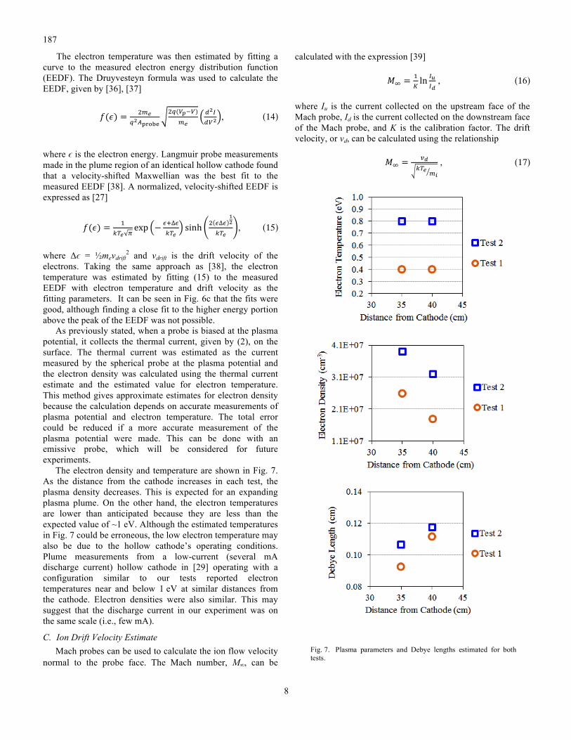
Fig. 7. Plasma parameters and Debye lengths estimated for both tests.
The electron temperature was then estimated by fitting a curve to the measured electron energy distribution function (EEDF). The Druyvesteyn formula was used to calculate the EEDF, given by [36], [37]
𝑓(𝜖) = !!!!!!!"#$%
!!(!!!!)!!
!!!!!!
, (14)
where ϵ is the electron energy. Langmuir probe measurements made in the plume region of an identical hollow cathode found that a velocity-shifted Maxwellian was the best fit to the measured EEDF [38]. A normalized, velocity-shifted EEDF is expressed as [27]
𝑓(𝜖) = !!!! !
exp − !!∆!!!!
sinh ! !∆!!!
!!!, (15)
where Δϵ = ½mevdrift2 and vdrift is the drift velocity of the
electrons. Taking the same approach as [38], the electron temperature was estimated by fitting (15) to the measured EEDF with electron temperature and drift velocity as the fitting parameters. It can be seen in Fig. 6c that the fits were good, although finding a close fit to the higher energy portion above the peak of the EEDF was not possible.
As previously stated, when a probe is biased at the plasma potential, it collects the thermal current, given by (2), on the surface. The thermal current was estimated as the current measured by the spherical probe at the plasma potential and the electron density was calculated using the thermal current estimate and the estimated value for electron temperature. This method gives approximate estimates for electron density because the calculation depends on accurate measurements of plasma potential and electron temperature. The total error could be reduced if a more accurate measurement of the plasma potential were made. This can be done with an emissive probe, which will be considered for future experiments.
The electron density and temperature are shown in Fig. 7. As the distance from the cathode increases in each test, the plasma density decreases. This is expected for an expanding plasma plume. On the other hand, the electron temperatures are lower than anticipated because they are less than the expected value of ~1 eV. Although the estimated temperatures in Fig. 7 could be erroneous, the low electron temperature may also be due to the hollow cathode’s operating conditions. Plume measurements from a low-current (several mA discharge current) hollow cathode in [29] operating with a configuration similar to our tests reported electron temperatures near and below 1 eV at similar distances from the cathode. Electron densities were also similar. This may suggest that the discharge current in our experiment was on the same scale (i.e., few mA).
C. Ion Drift Velocity Estimate Mach probes can be used to calculate the ion flow velocity
normal to the probe face. The Mach number, M∞, can be
calculated with the expression [39]
𝑀! = !!ln !!
!! , (16)
where Iu is the current collected on the upstream face of the Mach probe, Id is the current collected on the downstream face of the Mach probe, and K is the calibration factor. The drift velocity, or vd, can be calculated using the relationship
𝑀! = !!!!! !!
, (17)

187
9
where (kTe/mi)½ is the ion acoustic velocity. Although (16) and (17) have been applied successfully to calculate the ion flow velocity in magnetized plasmas, it is much more difficult to calculate this velocity using a Mach probe in an unmagnetized plasma. References [28], [40], [41] describe the challenges of using Mach probes to make accurate velocity measurements in unmagnetized plasmas.
In unmagnetized plasmas, there is little agreement on the Mach probe calibration factor. It is influenced by a variety of parameters, including the ion temperature, which was not measured in this experiment. Hutchinson’s particle-in-cell (PIC) code found K ≈ 1.34, and others have found similar K values experimentally, so we use K ≈ 1.34 in our ion velocity estimate [42]. However, models have also found calibration factors that are smaller, which would predict larger Mach numbers [39].
Table IV shows the estimated ion drift velocities. The plasma in this experiment was unmagnetized, so the flow velocities that were calculated can only offer a qualitative sense of how the velocity changes with position and between tests. The estimated drift velocity appears to increase as the probes move closer to the cathode in each test set. Also, the estimated drift velocity is higher in Test 2 than Test 1. There are more high-speed ions closer to the hollow cathode plasma source and at lower flow rates. This is likely due to charge exchange collisions. The observed increase in drift velocity is likely associated with a larger fractions of beam ions than CEX ions. A more precise flow velocity measurement and an ion temperature measurement would be needed to conclude that the ion drift was actually mesothermal.
TABLE IV. ESTIMATED ION DRIFT VELOCITY FROM MACH PROBE
Test Set Probe Distance
(cm) Ju/Jd Estimated Ion Drift
Velocity (m/s) K = 1.34
Test 1
35 4.6 629 40 2.8 425
Test 2
35 5.9 1035 40 4.4 864
D. Comparison of the Plasma Environment with the Laboratory Environment The laboratory environment is compared with the LEO
environment in Table V. Generally, the laboratory plasma captures several key elements of the LEO environment. The Debye length is about 1 mm for both tests, so the spherical, cubic, and planar probes, each 1 cm across, have characteristic dimensions of about 10λD. The probe dimensions, scaled by the Debye length, are approximately representative of anode dimensions in LEO. Normalized by the electron temperature, the maximum probe bias in Test 1 and Test 2 was 175kTe/q and 88kTe/q, respectively. The maximum voltage of 70 V in Test 1 and Test 2 would be roughly 17 V and 8 V, respectively, in LEO, assuming kTe/q is around 0.1 eV.
This experiment does not replicate magnetic field effects, however. The magnetic field value reported in Table IV was
estimated from International Geomagnetic Reference Field-11 model and was not measured. A stronger magnetic field could be produced in future experiments with a Helmholtz coil. It is also important to generate a high-speed plasma to simulate LEO. The plasma flow velocity was not accurately measured, so it will be important so measure this.
TABLE V. COMPARISON OF IONOSPHERIC PLASMA ENVIRONMENT WITH THE LABORATORY ENVIRONMENT
Parameter Typical Ionosphere
Laboratory Range
Plasma Density, ne (cm–3) 104–106 1×10⁷–4×10⁷
Electron Temperature, kTe/q (eV) 0.1–0.2 0.4–0.8
Ion mass, mi (g) 2.66×10⁻²³ 21.8×10⁻²³
Magnetic field, B (G) 0.35 0.54
Representative bias voltage, Vp,max (V) 70 70
Calculated Parameters
Debye length, λD (cm) 0.2–3.3 0.1
Gyroradius, rL (cm) 2–3 3–4
Anode radius, rp (cm) 1–5 cm 0.5 cm
Scaling Parameters
rp / λD 0.3–25 5
rp / rL 0.3–2.5 0.1–0.2
Vp,max/ Te 700 88–175
VI. EXPERIMENTAL RESULTS:GEOMETRY COMPARISON In this section, we address the current collection behavior
of the cubic and planar probes and compare the characteristics with the spherical probe and with theory. The measured currents of the probes are compared against the OML and WLP models in Fig. 8, which were calculated for a 1-cm diameter sphere. We are interested in collecting current in the electron saturation regime, so only voltages above the plasma potential are shown.
All of the current measurements in Test 1 and 2 are below the OML predicted current. The probe is larger than the Debye length, so the OML theory for thick sheaths cannot readily be applied. The Parker–Murphy and TSS-1R modified Parker–Murphy currents are not shown in Fig. 8. These expressions are better suited for current-collecting spheres that are large with respect to the gyroradius (i.e., rp>rL), so we do not expect the expressions to accurately predict the collection current.
The measured I–V curves rise more quickly at 35 cm then at 40 cm. This is likely due to the rise in electron density from 40 cm to 35 cm, which would increase the slope of the curves. Also, there is less CEX thermal plasma at 35 cm than at 40 cm and this may impact the I–V characteristic.
In both tests, the spherical probe displays a nearly linear I–V characteristic from about 40 V to 70 V. The cubic probes current collection behavior is somewhat similar to that of the spherical probes, although there is a noticeable difference. The slope of the cubic probe transitions from nearly flat to a steep

187
10
(a) (b)
(c) (d)
Fig. 8. Current as a function of voltage for the sphere, plate, and cube collector geometries from the first test set at distances of (a) 35 cm and (b) 40 cm and from the second test set at (c) 35 cm and (d) 40 cm. The voltage starts at 5 V because the current is in the electron saturation region the the plasma potential is about 5 V for each test.
linear slope. Although this is not precisely understood, we believe that at potentials slightly above the plasma potential, the sheath is relatively thin and the cubic probe’s faces collect current like planar collectors. At larger potentials, the sheaths at the probe’s corners, edges, and faces expand outwards and the I–V characteristic takes on a nearly linear slope. The slope may be larger than the sphere because the cube has almost twice the surface area of the sphere and the corners and edges enhance current collection. The cubic probe was made from aluminum, which is known to form oxidation layers when exposed to air, and it is also possible that this also impacted collection. It will be important in future experiments to tests with probes with similar conductive coatings.
The planar probe characteristic has a similar shape as the cube, transitioning from nearly flat to a linear upward slope. The slope of the planar probe’s I–V characteristic at large potentials is not as steep as the slope of the cubic probe’s I–V characteristic. Additional experiments with more precise measurements of the plasma parameters and simulations would be needed to better explain and predict the current-collection behavior of the probes.
Additionally, the probes’ current collection characteristics can be compared to the current predicted by the WLP model. In the voltage range tested, the WLP model gives rough, order-of-magnitude estimates of the spherical, cubic, and planar probes. Thus, based on this limited data set, we believe the WLP model provides a reasonable estimate for collection

187
11
(a)
(b)
Fig. 9. Normalized current versus normalized voltage for the sphere, plate, and cube collector geometries from the first and second test sets. The normalized current characteristics at 35 cm and 40 cm were nearly identical for both tests, so only the 35 cm distance is shown.
current. However, the WLP model current collection characteristic has an entirely different slope than any of these slopes. All of the probes tested assume a linear or nearly linear I–V characteristic at large potentials. At large bias voltages, the calculated WLP current scales with V0.85 while the other probe currents scale, roughly, with V. This suggests that if the voltage range were to increase, the WLP theory would be a less accurate model for estimating the current collection characteristics of the spherical, cubic, and planar probes. The WLP model was developed empirically for interpreting Langmuir probe sweeps in the LEO environment, and perhaps
the shape of its I–V characteristic is due, in part, to the mesothermal plasma flow or to magnetic field effects when the sheath becomes large with respect to the gyroradius. To evaluate this, it would be necessary to model the current collection behavior or perform an experiment with a high-speed plasma and an appropriately scaled magnetic field.
Fig. 9 shows normalized current characteristics in tests 1 and 2. The normalization used the total surface area of each probe. Normalization allows the current collected per unit surface area of each of the probes to be compared, giving a measure of “collection efficiency.” The bias voltages in Fig. 9 are normalized by the electron temperature. Test 1 has a lower estimated electron temperature than test 2, so the normalized bias range is larger in test 1 than test 2. The normalized current characteristics at 35 cm and 40 cm were nearly identical, so only the 35 cm distance is shown for each test.
The normalized current characteristics of the probes are well below the calculated OML current and on the same order of magnitude as the calculated WLP current. On a per-unit-area basis, the sphere is the most efficient collector, the cube is the least efficient, and the plate is between the sphere and the probe. The relatively low normalized current of the cubic probe’s normalized characteristic could be due to the inefficient collection on the probe’s large, flat faces. Although this is likely the reason, it could also be influenced by the wake structure of the cube. The wake may limit the effective collection area to the front face and, to a lesser extent, the sides. This is likely not the dominant factor, however, because the spherical probe would be impacted by the wake effect as well. It is also interesting to note that the planar probe collects nearly as much normalized current as the sphere. This may be attributed to current collection at the probe’s edges and corners. It should also be noted that if each of the probes’ currents were normalized by the minimum drag area, the planar probe would be the most efficient collector because it has the smallest cross-sectional area profile.
VII. EXPERIMENT NON-IDEALITIES Although the experiment captured several aspects of the
LEO environment, there are some areas that are not representative of LEO. The dominant ion species in LEO is oxygen while in the laboratory plasma it was xenon. Also, as mentioned previously, this experiment did not have a magnetic field scaled appropriate to simulate LEO.
In terms of measurement non-idealities, noise was quite prominent in the experiment, especially in the electron saturation regime, making it difficult to identify the plasma and analyze the data. In future experiments, an emissive probe could be used to provide a more accurate measurement of the plasma potential.
The spherical probe material may have contributed error to experimental measurements. The spherical probe was made of steel, and steel is prone to work function patchiness. This can lead to a non-uniform probe surface potential, and may lead to incorrect electron temperature measurements by “smearing” the electron retardation region. Work function patchiness can be due to the structure of the probe material or

187
12
contamination on the surface. Coating the spherical probe in a material like gold would prevent the base material from exhibiting work function patchiness [43]. To avoid lengthy cleaning procedures, additional techniques for deriving the plasma parameters from contaminated probes will be considered [8].
VIII. FUTURE TESTS We are planning on additional experiments to provide
better characterization of the hollow cathode plume properties and clarify characterizing these results. We will consider adding a magnetic field to further simulate the LEO environment. Finally, we plan to study the current collection behavior of porous samples, like a mesh sphere and a sphere made from radially-oriented conducting spokes.
IX. MITEE MISSION An in-orbit experiment is being planned by students at the
University of Michigan to demonstrate the ultra-small satellite-ED tether concept in the space environment. The Miniature Tether Electrodynamics Experiment (MiTEE) mission is a technology demonstration mission that will utilize CubeSat capabilities to deploy a ChipSat-tether system and assess the key dynamics and electrodynamics essential to the system's successful operation. Starting as a 1U CubeSat, a tethered picosatellite body of approximately 8 cm × 8 cm × 2 cm will be deployed from the CubeSat. The central questions motivating the mission include: (I) (Primary) Can the miniature tether provide stable, practical thrust for drag make-up and basic propulsion for “smart phone” sized ultra-small satellites? (II) (Secondary) Can the miniature tether and picosatellite system serve in other roles? This could include, among others, that the miniature tether could be the basis for a useful, enhanced antenna for communication with the ground. The MiTEE mission will provide on-orbit characterization of the electron emission and collection systems.
X. SUMMARY AND CONCLUSION The experimental results provide a better understanding of
the current collection behavior of the planar and cubic probes. We have confidence in these results because the laboratory environment approximated many of the conditions experienced in LEO. The Debye length relative to the probe size was approximately representative of LEO. However, mesothermal plasma flow and magnetic field effects would need to be considered to more closely approximate the LEO environment.
In the voltage range tested, the WLP theory used to estimate current collection in previous studies provides a rough, order-of-magnitude estimate of the collection current. The spherical probe generally collected more current than the planar probe and the cubic probe, although the cubic probe current intersects and eventually passes the spherical probe current for large bias voltages in Test 1. On a per-surface-area basis, the spherical probe is the most efficient collector. However, on a per-drag-area basis, the planar probe is the most efficient collector.
ACKNOWLEDGMENT I.C. Bell would like to thank K. Trent for providing
knowledge and laboratory training, ElectroDynamic Applications, Inc. for assisting with assembly and repair of the hollow cathode, and the support of the Plasmadynamics and Electric Propulsion Laboratory director, Prof. Alec Gallimore.
REFERENCES [1] D. J. Barnhart, T. Vladimirova, A. M. Baker, and M. N. Sweeting, “A
low-cost femtosatellite to enable distributed space missions,” Acta Astronaut., vol. 64, no. 11–12, pp. 1123–1143, Jun. 2009.
[2] D. Barnhart, T. Vladimirova, M. Sweeting, R. Balthazor, L. Enloe, H. Krause, T. Lawrence, M. Mcharg, J. Lyke, J. White, and A. Baker, “Enabling Space Sensor Networks with PCBSat,” AIAAUSU Conf. Small Satell., Aug. 2007.
[3] S. Janson and D. Barnhart, “The Next Little Thing: Femtosatellites,” AIAAUSU Conf. Small Satell., Aug. 2013.
[4] D. J. Barnhart, T. Vladimirova, and M. N. Sweeting, “Very-Small-Satellite Design for Distributed Space Missions,” J. Spacecr. Rockets, vol. 44, no. 6, pp. 1294–1306, Nov. 2007.
[5] I. C. Bell, J. K. McTernan, B. Gilchrist, and S. G. Bilen, “Investigating Miniature Electrodynamic Tethers and Interaction with the Low Earth Orbit Plasma,” in AIAA SPACE 2013 Conference and Exposition.
[6] L. T. Williams, V. S. Kumsomboone, W. J. Ready, and M. L. R. Walker, “Lifetime and Failure Mechanisms of an Arrayed Carbon Nanotube Field Emission Cathode,” IEEE Trans. Electron Devices, vol. 57, no. 11, pp. 3163–3168, Nov. 2010.
[7] C. M. Marrese, A. D. Gallimore, W. A. Mackie, and D. E. Evans, “The design of a cathode to operate in an oxygen-rich environment,” 1997.
[8] J. K. McTernan and S. G. Bilen, “Electrodynamic Tether Systems on Small-Scale Spacecraft Using Dual-Purpose Materials for the Plasma-Spacecraft Interface,” 2013.
[9] D. J. Barnhart, “Very Small Satellite Design for Space Sensor Networks,” University of Surrey, Guildford, United Kingdom, 2008.
[10] “PocketQube,” Wikipedia, the free encyclopedia. 11-Apr-2014. [11] Z. Manchester, M. Peck, and A. Filo, “KickSat: A Crowd-Funded
Mission to Demonstrate the World’s Smallest Spacecraft,” AIAAUSU Conf. Small Satell., Aug. 2013.
[12] I. C. Bell, “Miniature Electrodynamic Tethers to Enhance Picosatellite and Femtosatellite Capabilities,” in 28th Annual AIAA/USU Conference on Small Satellites, Logan, Utah, 2014.
[13] D. R. Whaley, R. Duggal, C. M. Armstrong, C. L. Bellew, C. E. Holland, and C. A. Spindt, “100 W Operation of a Cold Cathode TWT,” IEEE Trans. Electron Devices, vol. 56, no. 5, pp. 896–905, 2009.
[14] F. F. Chen, “Langmuir probe diagnostics,” in Mini-Course on Plasma Diagnostics, IEEE-ICOPS Meeting, Jeju, Korea, 2003.
[15] J. G. Laframboise and L. W. Parker, “Probe design for orbit-‐‑limited current collection,” Phys. Fluids, vol. 16, no. 5, p. 629, May 1973.
[16] I. Langmuir and K. B. Blodgett, “Currents Limited by Space Charge between Concentric Spheres,” Phys. Rev., vol. 24, no. 1, pp. 49–59, Jul. 1924.
[17] L. W. Parker and B. L. Murphy, “Potential buildup on an electron-emitting ionospheric satellite,” J. Geophys. Res., vol. 72, no. 5, pp. 1631–1636, 1967.
[18] D. C. Thompson, C. Bonifazi, B. E. Gilchrist, S. D. Williams, W. J. Raitt, J.-P. Lebreton, W. J. Burke, N. H. Stone, and K. H. Wright, “The current-voltage characteristics of a large probe in low Earth orbit: TSS-1R results,” Geophys. Res. Lett., vol. 25, no. 4, pp. 413–416, 1998.
[19] W. J. Raitt, N. B. Myers, D. C. Thompson, P. M. Banks, B. E. Gilchrist, T. Neubert, P. R. Williamson, and S. Sasaki, “Recent experimental measurements of space platform charging at LEO altitudes,” Adv. Space Res., vol. 12, no. 12, pp. 49–52, 1992.
[20] E. Choiniere and B. E. Gilchrist, “Self-Consistent 2-D Kinetic Simulations of High-Voltage Plasma Sheaths Surrounding Ion-Attracting Conductive Cylinders in Flowing Plasmas,” IEEE Trans. Plasma Sci., vol. 35, no. 1, pp. 7–22, 2007.
187
13
[21] N. H. Stone, W. J. Raitt, and K. H. Wright Jr., “The TSS-1R electrodynamic tether experiment: Scientific and technological results,” Adv. Space Res., vol. 24, no. 8, pp. 1037–1045, 1999.
[22] D. L. Cooke and I. Katz, “TSS-1R electron currents: Magnetic limited collection from a heated presheath,” Geophys. Res. Lett., vol. 25, no. 5, pp. 753–756, 1998.
[23] É. Choinière, S. G. Bilén, B. E. Gilchrist, K. R. Fuhrhop, and A. D. Gallimore, “Experimental investigation of electron collection to solid and slotted tape probes in a high-speed flowing plasma,” Plasma Sci. IEEE Trans. On, vol. 33, no. 4, pp. 1310–1323, 2005.
[24] L. Conde, “An introduction to Langmuir probe diagnostics of plasmas,” 2011. [Online]. Available: http://plasmalab.aero.upm.es/~lcl/PlasmaProbes/Probes-2010-2.pdf. [Accessed: 30-Sep-2013].
[25] R. T. Bettinger and E. H. Walker, “Relationship for Plasma Sheaths about Langmuir Probes,” Phys. Fluids, vol. 8, no. 4, p. 748, Apr. 1965.
[26] A. Barjatya, C. M. Swenson, D. C. Thompson, and K. H. Wright, “Invited Article: Data analysis of the Floating Potential Measurement Unit aboard the International Space Station,” Rev. Sci. Instrum., vol. 80, no. 4, p. 041301, Apr. 2009.
[27] D. M. Goebel and E. Chu, “High-Current Lanthanum Hexaboride Hollow Cathode for High-Power Hall Thrusters,” J. Propuls. Power, vol. 30, no. 1, pp. 35–40, 2014.
[28] L. Oksuz and N. Hershkowitz, “Understanding Mach probes and Langmuir probes in a drifting, unmagnetized, non-uniform plasma,” Plasma Sources Sci. Technol., vol. 13, no. 2, p. 263, May 2004.
[29] G. Vannaroni, M. Dobrowolny, E. Melchioni, F. D. Venuto, and R. Giovi, “Characterization of the interaction between a hollow cathode source and an ambient plasma,” J. Appl. Phys., vol. 71, no. 10, pp. 4709–4717, May 1992.
[30] G. J. Williams Jr, T. B. Smith, M. T. Domonkos, A. D. Gallimore, and R. P. Drake, “Laser-induced fluorescence characterization of ions emitted from hollow cathodes,” Plasma Sci. IEEE Trans. On, vol. 28, no. 5, pp. 1664–1675, 2000.
[31] C. L. Enloe, L. H. Krause, M. G. McHarg, O. Nava, P. B. Shoemaker, E. Ehmann, and J. D. Williams, “Characterization of a plasma source for ground-based simulation of LEO plasma conditions,” in Proc. AIAA-5668, 2nd Int. Energy Convers. Eng. Conf, 2004, pp. 16–19.
[32] B. Rubin, C. Farnell, J. Williams, J. Vaughn, T. Schneider, and D. Ferguson, “Magnetic filter type plasma source for ground-based simulation of low earth orbit environment,” Plasma Sources Sci. Technol., vol. 18, no. 2, p. 025015, 2009.
[33] J. S. Miller, S. H. Pullins, D. J. Levandier, Y. Chiu, and R. A. Dressler, “Xenon charge exchange cross sections for electrostatic thruster models,” J. Appl. Phys., vol. 91, no. 3, pp. 984–991, 2002.
[34] A. J. Kelly, “Atom—Atom Ionization Cross Sections of the Noble Gases—Argon, Krypton, and Xenon,” J. Chem. Phys., vol. 45, no. 5, pp. 1723–1732, 2004.
[35] R. L. Merlino, “Understanding Langmuir probe current-voltage characteristics,” Am. J. Phys., vol. 75, no. 12, pp. 1078–1085, 2007.
[36] R. Shastry, A. D. Gallimore, and R. R. Hofer, “Near-Wall Plasma Characterization of a 6-kW Hall Thruster,” in 31st International Electric Propulsion Conference, IEPC-2009-133, Ann Arbor, MI, 2009.
[37] V. A. Godyak and V. I. Demidov, “Probe measurements of electron-energy distributions in plasmas: what can we measure and how can we achieve reliable results?,” J. Phys. Appl. Phys., vol. 44, no. 23, p. 233001, Jun. 2011.
[38] K. R. Trent, M. S. McDonald, R. B. Lobbia, and A. D. Gallimore, “Time-resolved Langmuir Probing of a New Lanthanum Hexaboride (LaB6) Hollow Cathode,” Sep. 2011.
[39] K.-S. Chung, “Mach probes,” Plasma Sources Sci. Technol., vol. 21, no. 6, p. 063001, Dec. 2012.
[40] I. H. Hutchinson, “The invalidity of a Mach probe model,” Phys. Plasmas 1994-Present, vol. 9, no. 5, pp. 1832–1833, 2002.
[41] E. Ko and N. Hershkowitz, “Asymmetry reversal of ion collection by mach probes in flowing unmagnetized plasmas,” Plasma Phys. Control. Fusion, vol. 48, no. 5, p. 621, 2006.
[42] I. H. Hutchinson, “Plasma Mach-probe with unmagnetized ions.” [43] L. H. Brace, “Langmuir Probe Measurements in the Ionosphere,” in
Measurement Techniques in Space Plasmas:Particles, R. F. Pfaff, J. E. Borovsky, and D. T. Young, Eds. American Geophysical Union, 1998, pp. 23–35.