anatomy of a high performance ip routercomlab/seminar/ovs1_ref5.pdf · anatomy of a high...
TRANSCRIPT

Anatomy of a High Performance IP Router
Florian BrodersenAlexander Klimetschek
{florian.brodersen, alexander.klimetschek}@hpi.uni-potsdam.de
Communication Networks Seminar 2003/04Hasso-Plattner-Institute, University of Potsdam
January 4, 2004
Abstract
In this paper we give an overview of the evolution of router architectures and show what
techniques are used to build high performance routers which can route packets at several
gigabit speeds. We start with an analysis of the jobs a router has to do and how traditional
or low-performance routers are built to accomplish these tasks. Therefore we describe the
traditional bus-based approach and show its limitations as well as the modern switch-based
layouts. Our focus lies on a detailed survey of the latter variants. The survey consists of de-
scribing the benefits and drawbacks of using packet-switching technology and a presentation
of different switch scheduling algorithms. Additionally, we show how the overall processing
power of routers can be increased by employing specific optimisations through the use of
intelligent hardware components or superior routing table data structures and lookup algo-
rithms. We conclude with a case-study of the Cisco 12416 internet router and an evaluation
of the latest efforts in router design.

Contents
1 Introduction 4
2 IP Router Analysis 5
2.1 IP Router Functionality . . . . . . . . . . . . . . . . . . . . . . . . . . . . . . . 5
2.1.1 Basic forwarding . . . . . . . . . . . . . . . . . . . . . . . . . . . . . . 6
2.1.2 Complex forwarding . . . . . . . . . . . . . . . . . . . . . . . . . . . . 7
2.1.3 Router-specific tasks . . . . . . . . . . . . . . . . . . . . . . . . . . . . 7
2.1.4 Division into slow and fast path . . . . . . . . . . . . . . . . . . . . . . 7
2.1.5 Router components . . . . . . . . . . . . . . . . . . . . . . . . . . . . . 8
2.2 Limits of Traditional IP Router Architecture . . . . . . . . . . . . . . . . . . . . 10
3 Modern IP Routers 13
3.1 Improvements at the component level . . . . . . . . . . . . . . . . . . . . . . . 13
3.1.1 Network Interface . . . . . . . . . . . . . . . . . . . . . . . . . . . . . 13
3.1.2 Forwarding Engine . . . . . . . . . . . . . . . . . . . . . . . . . . . . . 13
3.1.3 General Processing Module . . . . . . . . . . . . . . . . . . . . . . . . 14
3.1.4 Interconnection Unit . . . . . . . . . . . . . . . . . . . . . . . . . . . . 14
3.1.5 Router architectures comparison table . . . . . . . . . . . . . . . . . . . 15
3.2 Bus-based Architectures . . . . . . . . . . . . . . . . . . . . . . . . . . . . . . 15
3.3 Switch-based Architectures . . . . . . . . . . . . . . . . . . . . . . . . . . . . . 16
3.3.1 General switch idea . . . . . . . . . . . . . . . . . . . . . . . . . . . . . 16
3.3.2 Architectures . . . . . . . . . . . . . . . . . . . . . . . . . . . . . . . . 18
3.3.3 Buffering and queueing in switches . . . . . . . . . . . . . . . . . . . . 20
3.3.4 Crossbar Scheduling . . . . . . . . . . . . . . . . . . . . . . . . . . . . 26
3.3.5 Quality-of-service via hierarchical scheduling . . . . . . . . . . . . . . . 30
3.4 Routing table lookup optimisations . . . . . . . . . . . . . . . . . . . . . . . . . 32
3.5 Case study: Cisco 12000 series . . . . . . . . . . . . . . . . . . . . . . . . . . . 33
2

4 Conclusion and Outlook 36
List of Figures
1 Interregional Bandwidth . . . . . . . . . . . . . . . . . . . . . . . . . . . . . . 4
2 Simple router block diagram (FMC) . . . . . . . . . . . . . . . . . . . . . . . . 8
3 Traditional router architecture with single CPU and single memory (FMC) . . . . 10
4 Routing table entries in the BGP system . . . . . . . . . . . . . . . . . . . . . . 12
5 Detailed router block diagram (FMC) . . . . . . . . . . . . . . . . . . . . . . . 14
6 List of described router architectures . . . . . . . . . . . . . . . . . . . . . . . . 15
7 A 4-input crossbar interconnection fabric . . . . . . . . . . . . . . . . . . . . . 17
8 Modern switch based architecture with forwarding engines on line card (FMC) . 19
9 Two Schemes of the output queueing family . . . . . . . . . . . . . . . . . . . . 22
10 Scheme of crosspoint/distributed output queueing . . . . . . . . . . . . . . . . . 23
11 Scheme of input queueing . . . . . . . . . . . . . . . . . . . . . . . . . . . . . 24
12 Performance impact of head-of-line (HOL) blocking . . . . . . . . . . . . . . . 25
13 Scheme of combined input and output queueing . . . . . . . . . . . . . . . . . . 26
14 Summary of theN ×M switch queueing architectures . . . . . . . . . . . . . . 27
15 2DRR scheduling algorithm operating on the adjacency matrix . . . . . . . . . . 28
16 Example run of the Parallel Iterative Matching (PIM) algorithm . . . . . . . . . . 29
17 Cisco 12000 series . . . . . . . . . . . . . . . . . . . . . . . . . . . . . . . . . 33
18 Cisco 12416 . . . . . . . . . . . . . . . . . . . . . . . . . . . . . . . . . . . . . 34
19 Unicast and multicast queues . . . . . . . . . . . . . . . . . . . . . . . . . . . . 35
3

(a) 2001 (b) 2002
Figure 1: Interregional Bandwidth (http://www.telegeography.com)
1 Introduction
Within the last decade the internet has grown rapidly. As there are more and more users con-
nected to the internet and the per-user traffic is growing, networks are faced with increased
amount of traffic. This means that data has to be transmitted and processed at higher rates. Due
to advances in the research of transmission technology, currently more bandwidth is provided
than actually needed. Using Dense Wavelength Division Multiplexing (DWDM) technology in
fibre optic cables, transfer rates up to 80 Gbit/s per line can be achieved, which satisfies present
demands (figure 1). Being confronted with this high bandwidth, routers become the real bottle-
necks.
Traditional hardware routers could not handle this amount of data anymore because they
were limited by their architecture which typically consisted of only one processor and one central
memory unit. Routing and route processing was done purely in software and their performance
was limited by the processor.
In order to solve this problem, new router architectures are needed. Unlike traditional routers,
which used a bus for internal communication, present-day routers are based on a switch. On one
hand this enables fast routing at gigabit speed, but on the other hand this leads to new prob-
lems, such as input and output blocking. The purpose of this paper is to illustrate the different
approaches towards these new designs and to show up solutions for specific problems like fast
routing table lookup. To understand the central part of modern routers, the switch, we will take
4

an in-depth look at the problems of building a high-performance switch.
We will neither cover routing mechanisms nor routing protocols, such as RIP, BGP or OSPF.
For further information on routing protocols see [Bak95] [Mal98] [RL95] [Moy98].
Contents of this paper
Section 2 begins with analysing the functionality of a router. After explaining the steps the router
has to do, like packet forwarding and route processing, we identify the abstract router compo-
nents which provide this functionality. At last we will look at the traditional router architecture
and show its limitations to provide a motivation for new designs.
In section 3 we talk about the modern switch based router architectures. After giving a short
overview of how the different components can be optimised, we briefly discuss some variants of
the traditional bus-based router architecture. The main part consists of an in-depth analysis of
the switch concept. We will conclude with a presentation of a commercial router.
In the last section we will show some open problems and ask what the next router generation
will look like.
2 IP Router Analysis
2.1 IP Router Functionality
The basic IP router functionality is given by the path a typical IP packet takes through the router:
it is received at the inbound network interface, the appropriate outbound network interface is
determined by looking at the header of the packet and by consulting the routing table and is then
finally forwarded to the outbound network interface, which will transmit it to the next hop. This
is true for most of the packets, but there are also packets received at the router, which require
special treatment by the router itself.
Going into more detail, a classification of packets by their destination is helpful. Packets
destined for the router itself include automatic routing protocol messages (like RIP, BGP or
OSPF) as well as system configuration and management requests. All other packets, with a
destination outside the router, have to be either forwarded or rejected. Most of the time the
forwarding decision can easily be computed. In some cases it is more complex because packet
5

translation, traffic prioritisation and packet filtering need to take place before the packet can
eventually be delivered.
2.1.1 Basic forwarding
As described in “Requirements for IP Version 4 Routers” [Bak95] and “IP Router Architectures:
An Overview” [Awe99] the following actions must be done in order to properly forward a packet.
• IP Packet Validation:First of all the router has to validate the IP packet. Only well-formed
packets can be further processed, otherwise the packet is discarded. This test ensures that
(a) the version number is correct, (b) header length field is valid and (c) the value of the
header checksum field is equal to the calculated header checksum [BBP88].
• Packet Lifetime Control:Routers must decrement the time-to-live (TTL) field and discard
the packet if the value is zero or negative. In this case an ICMP error message is sent to
the original sender.
• Checksum Recalculation:Due to the fact that the TTL field has been modified, the header
checksum needs to be recalculated. When the TTL field is only decremented by one, it is
easy to compute the new checksum [MK90].
• Destination IP Address Parsing and Table Lookup:To determine the output port, the des-
tination IP address of the packet is taken to find a matching entry in the routing table. This
reveals whether the packet should be delivered locally, to a single output port (unicast) or
to a set of output ports (multicast).
• Fragmentation:To meet the Maximum Transmission Unit (MTU) of the outbound network
interface, packets might need to be split into smaller fragments. Because fragmentation
is considered harmful by virtue of its massive impact on performance, a method called
“Path MTU Discovery” was developed to avoid fragmentation on the path of an IP packet
[MD90].1
• Handling IP Options:Although very few packets require IP options handling and parsing,
their processing must be implemented [Pos81].
1The smallest MTU is discovered by sending packets with the “IP Don’t Fragment Bit” set. This forces a router,which would have to fragment the packet, to send an ICMP error message back to the sender. This error messageshould contain the value of the MTU possible at that router. The sender reduces the size of the packets and proceedsthis way until a packet successfully reaches its final destination.
6

2.1.2 Complex forwarding
Depending on the field of application, routers sometimes have to perform additional steps when
forwarding a packet. We call this complex forwarding and typical elements of it are:
• Packet Translation:Due to the lack of public IP addresses people are forced to use one
address for several hosts. A router acting as a gateway for local networks has to map local
addresses to the routers public IP address and vice versa. This feature is called network
address translation (NAT) and is achieved by maintaining a list of connected hosts and
translating incoming and outgoing packets.
• Traffic Prioritisation: In order to meet customer’s requirements, routers must be able to
guarantee a certain quality of service (QoS), for example delivering a fixed amount of
packets at a constant rate. New applications like multimedia streaming over the internet
demand this.
• Packet Filtering:Routers often act as firewalls for networks. Therefore they have to filter
packets according to firewalling rules by looking at the packets contents.
2.1.3 Router-specific tasks
In the last paragraphs we talked about packets not destined for the router, which make up the
largest part of arriving packets. A relative small amount of packets has to be interpreted by the
router itself.
• Routing Protocols:Routers need to support different routing protocols in order to be able
to send and receive route updates from other routers. These updates lead to automatic
modifications of the routing table.
• System Configuration and Management:Administrators can manually modify the config-
uration of the router. This includes modifications of the routing table and their implicit
propagation to other routers by sending route updates.
2.1.4 Division into slow and fast path
All tasks the router has to execute can be divided into time critical (fast path) and non-time
critical (slow path) operations depending on their frequency. Time critical operations are those
7

which affect the majority of packets and do not require special treatment. This includes IP packet
validation, packet lifetime control, checksum recalculation, destination IP address parsing and
table lookups. On the other hand, IP options handling, fragmentation and error handling as well
as all router-specific tasks are regarded as non-time critical. Complex forwarding tasks are not
commonly implemented in routers but none the less tend to be time critical operations. For
example when the router is also used as a firewall every packet must be filtered.
Otherwise, if packet translation is required, this does not necessarily need to be done with all
packets.
When building a high performance router it must be ensured that the fast path is implemented
in a highly efficient and optimised manner. It is also very important that the slow path does not
affect the fast path, in other words, time critical operations must have the highest priority under
any circumstances. Most of the architectures and optimisations described in the next section will
therefore concentrate on the fast path. The research in this area focuses on the fast path, too.
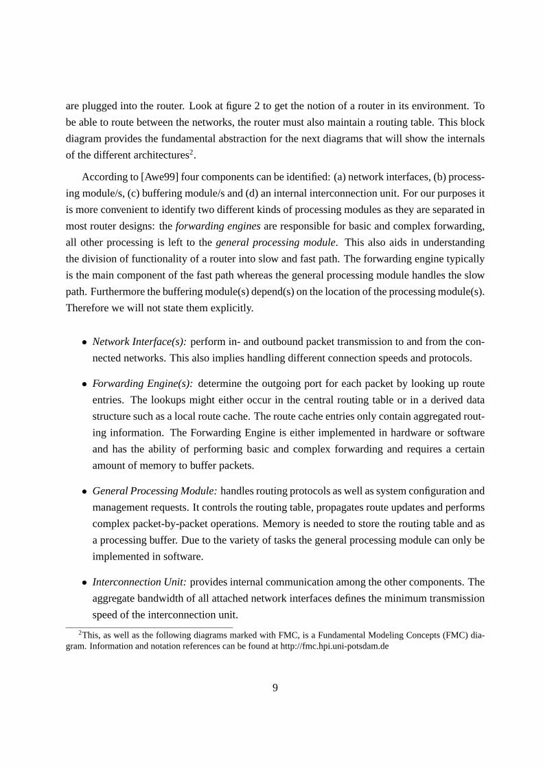
2.1.5 Router components
Figure 2: Simple router block diagram (FMC)
From the architectural point of view routers can be divided into several components. All
of the functionality mentioned above must be distributed among them. These components are
placed within the router and are connected to the environment via different network links that
8
are plugged into the router. Look at figure 2 to get the notion of a router in its environment. To
be able to route between the networks, the router must also maintain a routing table. This block
diagram provides the fundamental abstraction for the next diagrams that will show the internals
of the different architectures2.
According to [Awe99] four components can be identified: (a) network interfaces, (b) process-
ing module/s, (c) buffering module/s and (d) an internal interconnection unit. For our purposes it
is more convenient to identify two different kinds of processing modules as they are separated in
most router designs: theforwarding enginesare responsible for basic and complex forwarding,
all other processing is left to thegeneral processing module. This also aids in understanding
the division of functionality of a router into slow and fast path. The forwarding engine typically
is the main component of the fast path whereas the general processing module handles the slow
path. Furthermore the buffering module(s) depend(s) on the location of the processing module(s).
Therefore we will not state them explicitly.
• Network Interface(s):perform in- and outbound packet transmission to and from the con-
nected networks. This also implies handling different connection speeds and protocols.
• Forwarding Engine(s):determine the outgoing port for each packet by looking up route
entries. The lookups might either occur in the central routing table or in a derived data
structure such as a local route cache. The route cache entries only contain aggregated rout-
ing information. The Forwarding Engine is either implemented in hardware or software
and has the ability of performing basic and complex forwarding and requires a certain
amount of memory to buffer packets.
• General Processing Module:handles routing protocols as well as system configuration and
management requests. It controls the routing table, propagates route updates and performs
complex packet-by-packet operations. Memory is needed to store the routing table and as
a processing buffer. Due to the variety of tasks the general processing module can only be
implemented in software.
• Interconnection Unit:provides internal communication among the other components. The
aggregate bandwidth of all attached network interfaces defines the minimum transmission
speed of the interconnection unit.
2This, as well as the following diagrams marked with FMC, is a Fundamental Modeling Concepts (FMC) dia-gram. Information and notation references can be found at http://fmc.hpi.uni-potsdam.de
9

Figure 3: Traditional router architecture with single CPU and single memory (FMC)
These components will be used to further illustrate the various architectures. We will always
refer to those terms.
2.2 Limits of Traditional IP Router Architecture
The layout of traditional IP routers resembles the typical computer layout. It consists of a single
general processing module with an integrated forwarding engine, a simple bus representing the
interconnection unit and several low speed network interfaces as depicted in figure 3. All func-
tionality (packet processing and forwarding) is implemented in software and runs on a general-
10

purpose central processing unit (CPU). In the past this completely satisfied the requirements of
low traffic and low bandwidth networks and provided the necessary functionality at relatively low
cost. But since transmission technology and the demand for high speed communication quickly
evolved, routers operating at the backbones of the internet have to cope with more data in shorter
time. One can easily see that the traditional approach has various drawbacks when it comes to
handling high load. These will be discussed in the following.
First of all the overall processing speed is definitely limited by the single CPU. It has to
process every packet, but the processing rate of the CPU cannot be increased by large amounts,
because CPU speed is physically limited. More over the implementation of routing in software
is inefficient since the operations of the fast path are restricted to a small set which can be imple-
mented directly in hardware (as we will see later). General purpose CPUs are good at executing
a lot of different applications.
As we stated earlier, the slow path should not influence the fast path. Combining forwarding
engine and general processing module in a single CPU does not adhere to this policy.
The growth of networks in the last years resulted in increasing size of the routing tables
(figure 4 shows that the table sizes of routers using the BGP routing protocol has grown from
about 20,000 entries in 1994 to 160,000 entries today). This in turn means that the routing table
lookup is slowed down and delays the actual packet forwarding. In the traditional architecture,
which uses ordinary memory to store the routing table, an approach to improve the table lookup
time is missing.
The interconnection unit, in this case a conventional bus structure, is by any means the biggest
problem in this design because every packet has to pass it at least twice, once from the incoming
network interface to the memory and after being processed by the CPU to the outgoing network
interface. Though only the packet header is needed to determine the outgoing network interface,
the whole packet including the large data portion is transfered across the bus. Another constraint
of most bus systems is the missing support for selective multicasting. Broadcasting is easy to
achieve, because it targets all members on the bus, but selective multicasting, where only a subset
of all members are recipients of a message, is difficult to realise.
In order to give the reader an impression of how fast a router must operate these days we will
present a simple example of a 16-port IP router, each port operating at 2.5 Gbit/s (typical fibre
optic link speed)3. Further we take 250 Bytes as a mean value for the length of a standard TCP
segment. Considering that for every incoming packet a forwarding decision has to be computed
3Many fibre optic high speed links operate at 10 Gbit/s nowadays.
11

Figure 4: Routing table entries in the BGP system over the last 10 years (http://bgp.potaroo.net)
the router must be able to make 20 million decisions per second, a decision every 50 ns.
16 · 2.5 Gbit/s8 · 250 Bytes
= 20 · 106 Hz
Given that current SDRAM has an access time of 10 ns and large routing tables contain
tens of thousands entries, it is easy to see that this packet rate cannot be accomplished by this
traditional architecture.
Supposing that all 16 network interfaces may wish to transfer packets simultaneously the
interconnection unit has to support a bandwidth of16 · 2.5Gbit/s = 40 Gbit/s. This assumes an
improved design where the packets would only have to pass the bus once. According to [S+96]
the maximum bandwidth of buses is around 20 Gbit/s.
Considering the demands for high performance routing at multigigabit and terabit speed in
arbitrary complex networks, the traditional architecture is not suitable any more. It does not scale
well due to its inflexible structure and its described several bottlenecks.
12
3 Modern IP Routers
In this section we will present the new approaches in router design. In the last decade the ar-
chitectures of high performance routers changed from being bus based to switch based and in-
corporated many improvements over the old techniques. As a matter of fact routing at gigabit
speed is only possible by using a switch internally. In order to better understand the evolution of
router layouts we will briefly discuss the enhanced bus based layouts but our focus primarily lies
on switch based architecture and its particular problems. Therefore we will talk about queueing,
blocking, scheduling algorithms and different switch variants. After that we will show several
approaches to optimise the lookup of entries in the routing table. The section concludes with
a presentation of the popular Cisco 12000 series as an example for a current high speed switch
based router.
3.1 Improvements at the component level
The following will most importantly take a look at how to implement the “internal routing agent”,
as depicted in figure 5. This diagram is a direct refinement of figure 2. Each network link
is connected to a separate network interface card (NI), because these links can be of different
types. The actual routing agent is located between those network interfaces, that is why we call
it the “internal routing agent”.
3.1.1 Network Interface
Optimisations of network interfaces are not subject of this examination since they depend on
transmission technology and only connect the router with the networks. As we have seen in the
example calculation above, the router must be able to route packets at least at the combined rate
of all network interfaces.
3.1.2 Forwarding Engine
Due to the fact that the forwarding engine(s) are part of the fast path, they must be implemented
in a very efficient way. Their tasks are simple but time critical. In order to compute a forwarding
decision simple algorithms are used which can easily be coded in hardware. Therefore putting the
forwarding logic into hardware by using application specific integrated circuits (ASICs) gives an
13

Figure 5: Detailed router block diagram (FMC)
enormous performance boost. Additionally, the forwarding algorithms can be improved. Another
optimisation is combining network interfaces and forwarding engines in one unit, the so called
line card. This makes it possible to determine the destination of each incoming packet right after
it has reached the router and minimises the need for the packet to travel the interconnection unit
more than once. These forwarding engines need memory for the packets and special memory for
the route cache (see section 3.4), which both are placed directly on the line cards.
3.1.3 General Processing Module
As the general processing module is only responsible for executing non-time critical operations
no optimisation is needed. Its execution time does not affect the fast path. It only has to be
guaranteed that it does not affect other components execution. Nevertheless, it needs a large
memory for the main routing
3.1.4 Interconnection Unit
Generally, there are two different types of interconnection units, as we have already noted. The
bus is the traditional form and used in normal computers. A bus is a shared medium with multiple
members, but only one member can send at a time. This is sufficient for many applications where
14

high traffic across the bus is less important than the flexibility of adding or removing members.
However, in routers it is the central purpose to connect different network interfaces or line cards.
There are very often multiple independent connections between those, that can happen at the
same time. As a bus does not support this, a switch is needed. The layout of a switch allows
to route many connections in parallel, wherefore some kind of scheduler is needed, who decides
which routes to make. To implement a switch, various approaches have been made, which will
be presented in 3.3.
3.1.5 Router architectures comparison table
In order to give the reader an overview of all the different router architectures appearing in this
paper we have prepared a comparison table (see figure 6). The table lists the architectures at
the left and the possible combinations of components at the right. It is assumed that all layout
variants have a reasonable amount of network interfaces with links to other networks. Variants B
through D evolved from the traditional architecture A. E and F represent two types of the switch
based approach as there are many variants which differ only slightly. As we have stated earlier
our discussion focuses on the different switch implementation details and not on every possible
realisable architecture. In the following paragraphs we will shortly introduce the variants B
through F whereas A was already mentioned in section 2.
Architectures Forwarding General ProcessingInterconnectionEngine(s) Module(s) Unit
A (traditional) Central CPU BusB Multiple CPUs BusC on separate cardsCentral CPU Bus + Control BusD on line cards Central CPU BusE on separate cardsCentral CPU SwitchF on line cards Central CPU Switch
Figure 6: List of described router architectures
3.2 Bus-based Architectures
In this section we like to give an overview of the bus-based architectures (B,C and D) which
resulted in modifications of the traditional approach. The reason behind presenting them here
15

in this paper even though they are not used for high performance routers, is that it took quite a
while until the use of switches as interconnection units became common.
As we already identified in the previous section the traditional approach has several bottle-
necks. One of them which highly affects the overall processing power of a router is the routing
table lookup because it can only be performed by the single CPU. Therefore the first idea to
eliminate this bottleneck was to use multiple CPUs instead of one (architecture B). Still every
single CPU consisted of a general processing module with an integrated forwarding engine which
means that each CPU could perform forwarding and router-specific tasks. This resulted in su-
perior throughput compared to the traditional design because these tasks could be executed in
parallel.
But another issue was left open. The packets still had to pass the bus twice since the for-
warding decision could only be computed by the CPUs and the packets had to travel from the
incoming port to the memory of the CPU and then to their assigned output port. In order to solve
this problem it was realised that only the header portion of the packet which includes the desti-
nation address is needed to determine the output port. Hence, the idea was to split the packet into
two parts (header and data) and leave the data portion on the incoming port until the forwarding
decision was made. In order to quickly compute those decisions multiple independent forward-
ing engines were used. The router-specific tasks were handled by a single independent general
processing module (architecture C).
It still remained unsolved that the header portion had to travel the bus twice. But this problem
was addressed in the next step of the evolution of bus-based router architectures. It was taken
advantage of the fact that the forwarding decision can be computed as soon as the packets have
arrived at the router. For this reason the forwarding engines were placed right after the network
interfaces (architecture D). The combination of these two components is called a line card.
One must not forget that all these three designs were still based on a bus system which is a
serious bottleneck when it comes to transmission of vast amounts of packets. As we will see in
the following, superior architectures exist which use switches for internal communications.
3.3 Switch-based Architectures
3.3.1 General switch idea
A switch takes advantage of the fact that multiple members of the interconnection unit do not
always conflict with their requests. When member A has a message to send to member B, it has
16
Figure 7: A 4-input crossbar interconnection fabric [McK97]
no impact on a message from C to D, for example. These requests could be served in parallel
if there would be a dedicated line between the affected members. Exactly this is provided by
a switch: it basically connects each member with every other member and allows a dynamic
configuration of those connections. Aschedulercontrols the configuration of the switch by
establishing and releasing the connections inside the so-calledswitch fabric. The connections
to the outside are named input and output ports (to indicate the direction of the packet flow). A
router with network interfaces or line cards connected to the switch has one input port for each
card and one output port respectively.4
Several methods exist to connect each input with each output in a switch fabric, with the
crossbar as the most common. A crossbar is a net of interconnection lines, with switchable
crosspoints, as can be seen in figure 7. Crossbars can be implemented in CMOS operating at
high speed [MIM+97]. Other fabrics highly depend on the chosen general switch layout, which
are described in 3.3.3.
When using a switch for a router, it must be considered that switches operate with fixed
length packets, also called cells. Fixed length make the implementation much simpler because
all parts of the switch can work with the same clock rate and after one “time slot” all packet
transmissions have finished [McK97]. To be able to handle variable length packets, which is the
case with IP packets processed by a router, the switch must split those packets into cells at the
input and reassemble them at the output.
4One could also look at a time-multiplexed bus as a simple implementation of a switch [Awe99]. This sharedmedium switch is scheduled by continuously repeating time slots allocated for the members on the bus. This designis very limited in capacity, as we have seen in 2.2. Because it does not reflect the typical characteristics of the otherkinds of switches, we rather consider this as a typical bus and not as a switch implementation.
17

When talking about switches, we will useN for the number of input ports andM for the
number of output ports. The speed of the input lines will be denoted withS [bit/s], whereby we
simply assume they all have the same speed for a simpler examination.
3.3.2 Architectures
There are two basic architectures possible with a switch as the interconnection unit. The general
processing module is connected to the switch like the other components and is typically a CPU
with memory located on a special card. Note that the actual forwarding decision is still made in
the forwarding engines, not in the switch itself. It needs exact information of the output port(s)
for a given packet to be able to transfer it.
As in the bus-based architecture C, the forwarding engines are located on separate cards
in architecture E. The switch can provide higher throughput, but unfortunately the packets still
have to cross the interconnection twice. This does not take full advantage of the switch. The only
reason to use this architecture is to avoid merging network interfaces with forwarding engines on
line cards and to reduce the number of forwarding engines (which can be lower than the number
of network interfaces). That would make it easier and cheaper to add network interfaces at a later
time.
The modern reference architecture for high-performance routers is denoted as architecture F
in this paper (figure 8). In this design packets only have to cross the switch once which increases
the throughput of the switch a lot, compared to the previously described architecture. The general
packet flow is simple: after reaching the network interface the packets are put into a memory on
the line card, where the forwarding engine takes care of finding the next hop of the packet. These
hops can be another line card, where the according outgoing network interface is located, but also
the general processing module, which is connected to the switch like any other line card. Having
all components arranged as line cards around the central switch, helps in making the router more
flexible for later expansion, as it is done in the Cisco 12000 series (section 3.5), for example. The
“internal routing agent” found in diagram 5 is not directly visible, because the network interfaces
are not on separated cards, but part of the line cards, which also contain the forwarding engines.
One could imagine the “internal routing agent” as the dotted agent in figure 8.
18

Figure 8: Modern switch based architecture with forwarding engines on line card (FMC)
19

3.3.3 Buffering and queueing in switches
The benefit of a switch is to allow multiple transmissions in parallel. However, as the speeds of
the different connected links are different and the actual transmissions between these links vary
and might interfere with each other, not all outstanding transmissions can be handled at the same
time. This raises the need for some kind of memory inside the switch, which stores packets that
have to wait for their transmission. As we will see, the location of that memory is determinant
for the design of the switch, and therefore switches are categorised by it. The point that switches
handle packet flows, implies that those memories are queues5, thus we call the categorisation
“Queueing families”.
It is very convenient to see that there are three basic types: input queueing, output queueing
and shared buffer (“central queueing”). The memory is located either before the internal switch
fabric (what actually connects all inputs and outputs together) at the input ports, after the fabric
on the output ports or the fabric itself is a single large buffer.
There are still different variants of each basic type and an analysis reveals that the shared
buffer can be seen as a specific type of output queueing. The following will describe those
variants, examine their performances, exhibit what is needed in order to make it work properly
and provide their advantages and disadvantages.
Output Queueing
We start with the output queueing, because the simple nature of it can be seen as the “refer-
ence” design for a switch regarding throughput and delay. None the less certain issues prevent a
practical implementation wherefore the research in the last twenty years tried to reach the same
performance with other kinds of queueing. If output queueing would be easy to implement, less
would be known about input queueing and others.
Normal output queueingneeds a connection from every input port to every output port, con-
sisting of a filter (address or routing filter) and one output buffer for all input lines. All incoming
packets will be immediately transferred to all outputs, where the filter selects the packets destined
for that output and places them into the buffer (figure 9(a)).
First of all the output queueing has very good performance because it is internally non-
blocking (there is no buffer or delay between the input and output ports). Because packets are
5These are mostly First-In-First-Out (FIFO) queues, which can be simply implemented in hardware. It is alsopossible to take a random packet from those queues, but complexity is lower with strict FIFO-queues
20

queued directly at the output links to which they must be transmitted, this switch design is always
work conserving. This means that the output links will never suffer from starvation when there is
at least more than one packet about to be sent over it. As we will see later, other queueing types
do not necessarily ensure work conserving. The fact that the decision of which packet gets sent
next is made directly at a particular output link has another three advantages: multicasting, i.e.
broadcasting as well as selective multicasting, are easily achievable by selecting the appropriate
packets; delaying of packets can be controlled—this is more and more important for a sensible
handling of multimedia traffic; finally, general quality-of-service as demanded by customers can
be simply ensured by having multiple queues, one for each prioritisation level, that make up the
output buffer. A policy scheduler must decide to which level a packet belongs and put it into the
according queue, the output scheduler takes the packets from the prioritised queues according to
rules defined in a contract. More concerning scheduling can be found in section 3.3.5
With all these advantages, the question is: why is the normal output queueing not used in
real high performance routers or packet switchers? Because of two reasons: the memory used
must be working at(N + 1) · S speed6, because if an output receives packets from all inputs in
one cell time,N writes must occur to save the packets in this output queue and1 packet must be
read from the memory to transmit it to the output. Secondly, the internal crossbar must also work
N times faster than the output links in order to support the maximum ofN writes to the same
output buffer. This is called aspeedup(in this case a speedupK with K = N ). A speedup ofN
is impossible to built for largerN or higher line ratesS, whereas it would be best not to require
any speedup (K = 0). If we take the example presented in 2.2 withN = 16 ports operating at
S = 2.5 Gbit/s, one line in the crossbar would have to transfer16 · 2.5 = 40 Gbit/s, the entire
crossbar then needs a capacity of16 · 40 = 640 Gbit/s. These requirements are too high for the
implementation of both crossbars and memories.
Theshared bufferbelongs to the output queueing family, because it is a large memory shared
by all output links (figure 9(b)). This makes the memory better utilised than in the normal output
queueing. Packet contents can be distributed across the memory, only the pointers to the packet
locations must be stored in queues. These logical queues can be set up according to the particular
need: one queue for each output or queues per prioritisation and traffic flow. When exposed to
unicast traffic, the same performance as with normal output queueing is achieved.
Problems arise with multicast traffic, because there is generally not enough throughput to
store a packet in multiple queues (one for each output). Multicasting must therefore be imple-
6In the rest of the document, a memory throughput ofN will be measured inS line speed, so that we getN · S [bit/s] as the actual memory speed.
21

(a) Output queueing (b) Shared buffer
Figure 9: Two Schemes of the output queueing family
mented by copying a packet multiple times from a queue to the appropriate output ports. A
serious problem called Head-of-line blocking (HOL) will then occur. This prevents packets to
be transferred to a waiting output port because other packets in front of it can currently not be
transferred and therefore block the packets behind. See the discussion of input queueing below
for a more complete description of HOL and its serious impact on performance.
A shared buffer is impossible to implement for large and high performance switches, because
the large amount of required space and throughput cannot be achieved with today’s memory
technologies and HOL prevents a reasonable performance.
Crosspoint or distributed output queueingis an improved version of the normal output queue-
ing, as it has one queue for each input at each output. It is called crosspoint because the memory
parts are located at the joints of the internal crossbar (figure 10). A scheduler selects an appropri-
ate packet from one of theN buffers and passes it to the output link. No speedup is needed and
the memory only faces a maximum of two operations per cell time. But distributing the output
queues toN ·M memories is very inefficient, because the number of memories is quadratically
increasing (considering the common case ofN = M ) and we cannot share memory space due to
the split up.
There is another variant calledblock-crosspoint queueing, a combination of crosspoint and
shared memory queueing. Here, the crosspoint memories are combined to connect multiple
input and output ports to allow a sharing of memory, but there is still not one single memory as
in the shared buffer variant. This can be seen as a grouping of the memory blocks in crosspoint
queueing. It is useful for largerN , when a single shared buffer would need too much memory
throughput.
TheKnock-Out switch[YHA87] tries to combine the advantages of the (partly) shared mem-
22

Figure 10: Scheme of crosspoint/distributed output queueing
ory in normal output queueing and of less needed memory throughput in crosspoint queueing. A
buffer-less knock-out fabric puts the packets ofN incoming lines intoL queues, whereL <= N .
If more thenL packets arrive, onlyL will be stored and the rest will get lost. A good chosen
value forL can keep the packet loss at a very low rate, independent on the number of inputs.
Assuming uniform traffic, a value ofL = 8, for example, is sufficient to maintain the packet loss
rate at one packet per million.
Input Queueing
Not the actual dual of output queueing, the input queueing family has buffer memory at the input
ports and a large, buffer-less switching fabric7 which connects all inputs with all outputs. No
buffer is found at the output. Because the actual switching must happen inside the fabric, a
scheduler is needed, who decides which input lines are connected to which output lines (figure
11). These decisions can be made by looking at the input queues. The main advantage of input
queueing is that the internal switch fabric and the memories only have to operate at the line rate
S as opposed to the output queueing.
7typically a crossbar
23

Figure 11: Scheme of input queueing
There are two possibilities for the buffer at one input port: either one queue (simple input
queueing) or multiple queues, i.e. one per output or even more (advanced input queueing or
virtual output queues).
Simpleinput queueingsuffers from a serious problem, called Head-of-line (HOL) blocking.
This applies to any FIFO-queued packet systems, when only the first packet in the queue is
considered for the next action, i.e. taking that packet out of the queue and sending it out. If the
front packet (the head of the line) cannot be sent to an output port, because this output port is
blocked, the rest of the packets in the queue are also blocked. This is bad because very often
those packets are destined for a completely different output port and could be transferred, when
no other packets from other input lines contend for that output port.
An analysis of HOL blocking, assuming independent, identically distributed Bernoulli pro-
cesses with uniformly distributed destination ports, yields that under full load only2 −√
2 =
0.586 ≈ 58% throughput can be achieved (see figure 12).
HOL makes the simple input queueing unusable for high performance packet switches.Ad-
vanced input queueingwith virtual output queues(VOQ) remove the HOL blocking problem at
the cost of the complexity of the scheduler at the crossbar. If separate queues for each output port
exist at the input ports, no packet in front of others can block them any more, because they all
24

Figure 12: Performance impact of head-of-line (HOL) blocking [HK88]
have the same destination port. These virtual output queues can be compared with traffic lanes
at crossroads. It is obvious that cars (packets) with the same destination waiting in the same lane
(queue) cannot block each other. An important thing to consider is the maximum possible size
of the virtual output queues to prevent packet loss at the input.
Input queueing with VOQs is very popular and demands an intelligent scheduler for the
crossbar. Various algorithms are described in section 3.3.4.
Combined Input and Output Queueing
An interesting approach has been made to emulate an output queued switch by using input and
output buffers as well as a speedup in the switch fabric, called acombined input and output
queued(CIOQ) switch (see figure 13).
As written above, a speedup ofK means that the switch can transfer up toK packets from
its input ports to its output ports within one time slot. This time slot is the interval between
packet arrivals at the input ports. The output queued switch needs a speedup ofK = N , which
is very impractical. On the other hand, input queueing suffers from head-of-line blocking. The
question of interest is how much speedup is needed, so that a CIOQ switch behaves identically
25
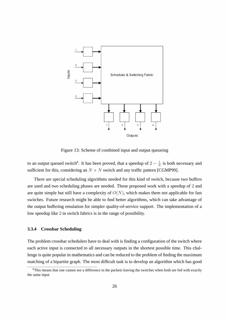
Figure 13: Scheme of combined input and output queueing
to an output queued switch8. It has been proved, that a speedup of2 − 1N
is both necessary and
sufficient for this, considering anN ×N switch and any traffic pattern [CGMP99].
There are special scheduling algorithms needed for this kind of switch, because two buffers
are used and two scheduling phases are needed. Those proposed work with a speedup of2 and
are quite simple but still have a complexity ofO(N), which makes them not applicable for fast
switches. Future research might be able to find better algorithms, which can take advantage of
the output buffering emulation for simpler quality-of-service support. The implementation of a
low speedup like2 in switch fabrics is in the range of possibility.
3.3.4 Crossbar Scheduling
The problem crossbar schedulers have to deal with is finding a configuration of the switch where
each active input is connected to all necessary outputs in the shortest possible time. This chal-
lenge is quite popular in mathematics and can be reduced to the problem of finding the maximum
matching of a bipartite graph. The most difficult task is to develop an algorithm which has good
8This means that one cannot see a difference in the packets leaving the switches when both are fed with exactlythe same input
26

Maximum Memorymemory No. of space Complexity
Architecture throughput memories utilisation Performance cost (problems)
Shared high-throughputBuffer
N + M 1 BEST BESTsingle memory
Output high-throughput mem.,Queueing
N + 1 M MEDIUM BESTexpensive sw. fabric
Crosspoint manyQueueing
2 N ·M WORST BESTmemories
Input bad throughputQueueing
2 N MEDIUM WORSTunder high load
Input + VOQ MEDIUM (sh.sp.) VERY GOOD complexQueueing
2 NWORST (part.sp.) (if...) scheduler
CIOQ - VERY GOOD expensiveSpeedup of K
K + 1 N + M MEDIUM(if...) switching fabric
Figure 14: Summary of theN ×M switch queueing architectures [Kat03]
fairness properties which, in other words, is starvation free and leaves no input unserved indefi-
nitely. There exist several deterministic maximum matching algorithms with good runtimes but
they always produce the same matchings on equal or similar situation. An unmatched input will
therefore stay unmatched what is considered to be unfair. For iterative algorithms it is also nec-
essary to examine the behaviour under heavy load because usually only a single iteration can be
achieved under these circumstances. The last requirement for scheduling algorithms is that an
implementation in hardware must be easy to achieve.
Two Dimensional Round-Robin Scheduler - 2DRR
The basic idea behind this algorithm is to represent all inputs, all outputs and all requests in one
matrix as can be seen in figure 15. In mathematics this is an adjacency matrix of a bipartite graph
with the input ports as one set of vertexes and the output ports as the other set. The edges in this
graph symbolise the requests.
The algorithm starts with accepting all requests on the main diagonal and ignores all other
requests which are on the same rows and columns as the accepted requests. This procedures
now continues with all other diagonals in left-to-right order until every requests is accepted and
a maximum matching is found.
Considering fairness this approach has several drawbacks. First of all, it is not very clever
27

Figure 15: 2DRR scheduling algorithm operating on the adjacency matrix
to always start with the main diagonal. It would be better to select the first diagonal in a round-
robin fashion. It is also unfair to have a fixed left-to-right method for choosing the succeeding
diagonals. For further information see references [LS94] and [PT03].
Parallel Iterative Matching - PIM
Parallel Iterative Matching (PIM) was developed by DEC System Research Center at beginning
of the 1990s [AOST93]. The algorithm tries to find a maximum matching in several iterations.
Each iteration consists of three steps (see figure 16):
• Request:Each unmatched input sends a request to every output for which it has a queued
cell.
• Grant: If an unmatched output receives any requests, it chooses one randomly to grant.
28

Figure 16: Example run of the Parallel Iterative Matching (PIM) algorithm
• Accept:If an input receives a grant, it accepts one by selecting an output randomly among
those that granted to this input.
Tests have shown that this algorithm converges to a maximal match inO(logN) iterations. In
each iteration3/4 of the remaining requests are eliminated [AOST93]. Under heavy load when
only a single iteration is possible this algorithm does not perform well because the throughput is
limited to (1− 1e) for large N, which is approximately 63 % for N= 16 [PT03].
Iterative SLIP - iSLIP
The iSLIP algorithm is based on the PIM algorithm and was developed by Nick McKeown as
part of his thesis in 1995[McK95]. The main difference is that it uses a round-robin instead of
a random schedule for figuring out which input or output is matched next. This is achieved by
maintaining different kind of pointers. It is also possible to apply a prioritisation scheme in order
to support classes of services.
• Request:Each unmatched input sends a request to every output for which it has a queued
cell.
• Grant: If an output receives any requests, it chooses the one that appears next in a fixed
round-robin schedule starting from the highest priority element. The output notifies each
input whether or not its request was granted.
• Accept: If an input receives a grant, it accepts the one that appears next in a fixed round-
robin schedule starting from its own output pointer. The output pointer of the round-robin
schedule is incremented to one location after the accepted output.
The iSLIP has some advantages over the PIM approach. First of all, it performs better than
PIM even under heavy load and is relatively easy to implement [PT03]. It can achieve 100 %
29

throughput in a single iteration for uniform traffic [McK99]. PIM has the problem that random
selection is difficult to achieve. Another issue is that iSLIP is more fair by virtue of its round-
robin schedule.
McKeown has recently developed another enhanced variant of the iSLIP algorithm called
ESLIP [McK97] which can handle unicast and multicast traffic simultaneously. It is discussed in
the case-study at the end of section 4 as it is employed in the Cisco 12000 series internet router.
Lowest Occupancy Output First Algorithm - LOOFA
Another algorithm called LOOFA follows an iterative approach, too [KPC+99]. It consists of the
following two steps which are performed at every iteration:
1. Each unmatched input sends a request to an output with the lowest occupancy among those
for which it has at least one queued cell.
2. Each output, upon receiving requests from multiple inputs, selects one and sends a grant
to that input.
Unlike PIM or iSLIP this algorithm requiresO(N ) iterations to perform correctly. The be-
haviour under heavy load when there is only time for fewer iterations is unpredictable. This
makes LOOFA unsuitable for use in high speed implementations. However, it is used as the
basis for another algorithm which does not have this limitation and provides almost similar per-
formance. This derived algorithm is called Approximate LOOFA (A-LOOFA) and further in-
formation about it can be found in the paper “Stress-Resistant Scheduling Algorithms for CIOQ
Switches” [KPC+99].
3.3.5 Quality-of-service via hierarchical scheduling
The current development and research concentrates on more support for quality-of-service in
routers. Therefore we give some general information about possible methods for this support.
There are different aspects of resource control or quality-of-service in modern routers. These
are listed in the following with an example of what it means (taken from [GM01]):
• Packet Filtering:Deny all traffic from ISP3 (on interface X) destined to E2.
30

• Policy Routing:Send all voice-over-IP traffic arriving from E1 (on interface Y) and des-
tined to E2 via a separate ATM network.
• Accounting & Billing:Treat all video traffic to E1 (via interface Y) as highest priority and
perform accounting for the traffic sent this way.
• Traffic Rate Limiting:Ensure that ISP2 does not inject more than 10Mbps of email traffic
and 50Mbps of total traffic on interface X.
• Traffic Shaping:Ensure that no more than 50Mbps of web traffic is injected into ISP2 on
interface X.
Handling all these requirements claims for a special scheduling. As we have seen, input
queueing demands a scheduler inside the switch anyway, therefore it is good to introduce the
notion ofhierarchical scheduling. Hereby the work can be split into three stages on one hand,
and into multiple levels on the other hand [Kat03]. Looking at the stages, thepolicer is the first
who analyses incoming packets, drops any non-conforming packets and puts them in several
queues for the next steps. Then theregulatorwill ensure the correct delay of packets according
to the contract. Finally theschedulerwill select the appropriate packets among all those who are
eligible and send them out. Very often only the policer and scheduler are present, the regulator
is not as much required as the other two stages.
The levels are used because different algorithms are needed to implement different poli-
cies. These work on the different levels and compose the hierarchical scheduler. Some “sub-
schedulers” operate on distinct queues, e.g. sorted by traffic priority. The results of those sched-
ulers are passed to another scheduler selecting the actual packet for the transmission. This can
be carried on in multiple stages.
There are three prominent kinds of scheduling: static priority scheduling is the most simple
form, which always selects the packets with the highest priority. If higher priority queues never
get empty, packets with lower priority will never be served, which is not wanted. To overcome
this problem, the order of priorities can be changed into different time slots, which represent
the percentage of throughput allowed for certain packets. The round-robin scheduling is another
form with better results. Lastly, weighted round robin (WRR) can produce smoother output,
because different classes of packets do not come up in groups but change more often. This
improves the delay for most of the packets. Another name for that is Weighted Fair Queueing
(WFQ).
31

3.4 Routing table lookup optimisations
Performing routing lookups is one of the time critical tasks a router has to do. Typically, the data
structure for storing routes is a tree, where each path in the tree from root to leaf corresponds to
an entry in the routing table. In order to figure out where a given packet has to go, the longest
matching prefix of the destination address in the packet must be found in the tree. This is achieved
by finding the longest path in the tree that matches the destination address of the incoming packet.
For example, if the destination address is 192.168.1.2 and two prefixes, 192.168 and 192.168.1,
can be found in the tree, the longest matching prefix is 192.168.1.
The algorithms solving this problem9 have a complexity proportional to the number of ad-
dress bits of the destination address. This means that in the worst case it takes time proportional
to the length of the destination address to find the longest matching prefix. For example IP ver-
sion 4 addresses have 32 bits and it might take up to 32 bit comparisons to find a matching entry.
Performance even gets worse when the algorithms need to backtrack.
Different approaches exist to optimise the routing table lookups. They can be loosely cate-
gorised in (a) use of better algorithms (b) avoid routing table lookups by using caches (c) com-
press routing table (d) hardware based techniques.
As we have seen earlier routing tables contain tens of thousands of entries. One idea to opti-
mise the lookups in those big tables is to use a hash table as a front-end to the table. Waldvogel
[M. 97] has presented a scalable hash based algorithm that can look up the longest prefix match
for an N bit address inO(logN) steps. This is achieved by maintaining a hash table for every
possible prefix length.
In order to optimise the time consuming routing table lookups it also came up to avoid routing
lookups and use route caches instead. That means the routing table is only consulted when there
is no appropriate entry in the route cache. Looking up an entry in the route cache is far easier
because only exact matching is used and not best matching as for the routing table. Route caches
are only useful when there is enough locality in traffic in other words when the cache hit rate is
high enough because the destinations of packets do not change very often.
The third approach is to somehow compress the routing table in order to make the lookups
faster [M.D97]. This is achieved by exploiting the sparse distribution of route entries in the
space of all possible network addresses to build a complicated but compact data structure for
the routing table. The address space is partitioned into three levels. Each level uses a separate
9Patricia: Practical Algorithm to Retrieve Information Coded in Alphanumeric
32

encoding scheme to compress the tree structure. The resulting data structure requires only 150-
160 KBytes to represent a table with 40000 routes [Tze98]. This table is small enough to fit into
the data cache of high-end processors and allows route lookups at gigabit speeds.
Another alternative is to put the routing table lookup in a so called content-addressable-
memory (CAM) in order to provide a constant lookup rate. Unlike conventional memory this
type of memory is able to operate in two different modes. In one mode, they act like standard
memory and may be used to store binary data. The other mode is called matching mode because
it permits searching of all the data in the CAM in parallel [GLD00]. Still this kind of memory is
very expensive and therefore not useful for large routing tables. Aside from using CAMs, putting
the route table lookup logic in hardware is also under active investigation.
3.5 Case study: Cisco 12000 series
This case study is based on the paper by Nick McKeown [McK97] where he focuses on the
design of the Cisco 12000 series interconnection unit and on online resources found on the Cisco
web site (http://www.cisco.com).
As can be seen in figure 17 the Cisco 12000 series consists of five different models:
Model Slots Switching Capacity
12416 16 320 Gbit/s12410 10 200 Gbit/s12406 6 120 Gbit/s12404 4 80 Gbit/s12016 16 80 (upgradeable to 320) Gbit/s
Figure 17: Cisco 12000 series
In the following we will concentrate on the 12416 because it is the model with highest switch-
ing capacity. It has 16 slots each of them operating at 10 Gbit/s (20 Gbit/s in both directions)
which provide an aggregate switching capacity of 320 Gbit/s. Every slot is equipped with a
hardware forwarding engine in order to quickly compute the destination of packets as soon as
they arrive at the router. The architecture of the 12416 router resembles the variant F in our
comparison table 6.
The interconnection unit used is a crossbar switch which operates with fixed length packets
(“cells”) and a speedup of 2. Due to their simplicity, switches can operate at very high speed and
33

Figure 18: Cisco 12416
furthermore have the advantage of supporting multiple transactions simultaneously. As we have
seen above they are internally non-blocking which means that it allows parallel input and output
to and from the network interfaces.
A centralised scheduler controls the switch and is responsible for selecting a configuration
of the switch appropriate for delivering cells from inputs to outputs at any cell time. Each step
of the scheduler takes exactly one cell time. The scheduler uses the ESLIP algorithm, which we
will explain further down, to schedule unicast and multicast traffic. Scheduling multicast traffic
is achieved by using fanout-splitting where copies of the input cells may be delivered to output
ports at any cell time and not at the same cell time as it is the case when no fanout-splitting is
used. The fanout of a cell is the number of outputs to which an input cell is to be delivered.
Unicast cells always have a fanout of one and multicast cells have a fanout greater than one.
Fanout splitting can somehow be categorised as a best effort method because cells that can be
delivered to output ports will get delivered as soon as the output ports are free.
It is also worth mentioning that the switch has two different kinds of queues for unicast
and multicast traffic. Virtual output queues are used for unicast cells to eliminate head-of-line-
blocking and multicast queues are used to enable simple packet replication for multicast traffic
34

Figure 19: Unicast and multicast queues [McK97]
as depicted in figure 19.
ESLIP scheduling algorithm
The ESLIP scheduling algorithm is a modified version of the iSLIP algorithm. ESLIP handles
unicast and multicast queues at the same time [McK97] as opposed to iSLIP which can only
handle unicast traffic.
The problem which all scheduling algorithms have to solve is to determine which cell waiting
in an input queue is going to be delivered next. The algorithm at hand starts with an initial
switch configuration without any connections between ports. It is an iterative algorithm with
each iteration consisting of three steps (1) request, (2) grant and (3) accept. At each iteration the
configuration of the switch is modified. The main idea behind the algorithm is that each input
port with cells waiting to be delivered should ask the appropriate output ports whether they are
willing to receive. After the output ports have signalised their state, the input port sends the cell.
Due to the fact that either a multicast cell or a unicast cell can be delivered at one cell time,
the scheduler needs to remember which of the input ports had already sent a cell and which of
the output ports had already received a cell. For unicast cells this is achieved by maintaining
grant pointersugi to the input ports at the output ports and maintaining accept pointersuaj to the
output ports at the input ports. For multicast cells all output ports have a common grant pointer
mg and all input ports have a common accept pointerma.
Now follows a detailed description of the steps:
35

• Request:In this step each input which has cells waiting to be delivered sends requests to
every output for which it has data. This applies to unicast and multicast cells. If the switch
uses prioritisation the request can also be prioritised.
• Grant: When an output receives any requests it chooses the one that appears next in fixed
round-robin schedule starting from the highest priority element. For determining the next
input the pointersugi and the pointermg are used (see above). Each input then is informed
whether its requests is serviced or not.
• Accept: If an input receives a grant it accepts the one that appears next in a round-robin
order, starting from the highest priority element. If a unicast cell can now be delivered the
pointersuaj andugi are incremented (j is the current output which sent the grant and i the
current input). The common pointersmg andma only get incremented when all the cells
of a multicast request could be delivered.
The algorithm stops when a configuration of the switch is reached where all active inputs and
outputs are correctly connected to each other.
4 Conclusion and Outlook
The look into a high-performance IP router exposed several central insights. Routers need a
very specialised architecture to fulfil the demands of todays networks, the normal computer
architecture is only applicable to routers for local area networks with low bandwidth. The modern
layout is based on a central switch, which has forced research in this area, but also gained from
it. Likewise, to improve the process of forwarding, many ideas on how to decrease the time it
takes to look up an entry in the routing table lookup have been proposed.
Still some issues remain open. Like we have seen in section 3.3.5 better and simpler imple-
mentation of QoS schedulers are necessary in order to satisfy all customer requirements in this
area such as traffic rate limiting or traffic shaping. Especially accounting of a particular type of
packets is difficult to achieve.
As more and more devices (PDAs, MDAs) get connected to the internet IPv4 will be replaced
by IPv6 which in turn requires routing of IPv6 traffic at gigabit or terabit speed. Due to the fact
that IPv6 address are 128 bit long the routing table size increases and route lookups become more
complex. Moreover the table size also increases by virtue of the constant growth of the networks
36

especially of the internet. This will require efficient lookup algorithms and intelligent methods
like content-addressable-memory for storing the table.
From our point of view the next generation of routers will still be switch based because
packet switching technology using crossbar switches is not yet exhausted. We have seen that
the overall design using switches is scalable; faster memories and crossbars can simply provide
more performance, linearly. The usage of multiple parallel crossbars can increase the throughput
of switch fabrics and applying Combined Input-Output Queueing makes it possible to use WFQ
scheduling algorithms to support better QoS control.
In our paper we have only examined the properties of electronic packet-switched routers but
researchers are trying to use optical components to build even faster routers. Recently a project
at Stanford University has started to proof that building a 100Tb/s internet router with an optical
switch fabric is possible. This approach has several advantages over the electronic approach.
Since optical components are already used inside routers in order to interconnect components, it
is tried to reduce the number of conversions between the optical and the electronic domain and
therefore increase processing power [McK03].
Studying the anatomy of high performance routers is challenging and fascinating at the same
time as it requires deep knowledge of many different domains in order to fully understand the
decisions of the router architects.
Glossary
2DRR 2 Dimensional Round Robin
ASIC Application Specific Integrated Circuit
BGP Border Gateway Protocol - RFC1771
CAM Content Addressable Memory
CIOQ Combined Input Output Queueing
CoS Classes of Service
CPU Central Processing Unit
DWDM Dense Wavelength Division Multiplexing
37
HOL Head Of Line
ICMP Internet Control Message Protocol - RFC792
IP Internet Protocol - RFC791
LOOFA Lowest Occupancy Output First Algorithm
MDA Mobile Digital Assistant
MTU Maximum Transfer Unit
NAT Network Address Translation
OSPF Open Shortest Path First - RFC2328
PDA Personal Digital Assistant
PIM Parallel Iterative Matching
QoS Quality of Service
RIP Routing Information Protocol - RFC1058
SDRAM Synchronous Dynamic Random Access Memory
TTL Time To Live
UDP User Datagram Protocol - RFC768
VOQ Virtual Output Queue
WFQ Weighted Fair Queueing
WRED Weighted Random Early Detection
References
[AOST93] T. Anderson, S. Owicki, J. Saxe, and C. Thacker. High-speed switch scheduling for
localarea networks, 1993.
[Awe99] James Aweya. IP Router Architectures: An Overview, 1999.
38
[Bak95] F. Baker. Requirements for IP Version 4 Routers, June 1995. IETF RFC 1812.
[BBP88] R. Braden, D. Borman, and C. Partridge. Computing the Internet Checksum,
September 1988. IETF RFC 1071.
[CGMP99] Shang-Tse Chuang, Ashish Goel, Nick McKeown, and Balaji Prabhakar. Matching
Output Queueing with a Combined Input Output Queued Switch.IEEE Journal on
Selected Areas in Communications, 17(6):1030–1039, December 1999.
[GLD00] Steven Guccione, Delon Levi, and Daniel Downs. A Reconfigurable Content Ad-
dressable Memory. InProceedings of International Parallel and Distributed Pro-
cessing Symposium, May 2000.
[GM01] Pankaj Gupta and Nick McKeown. Algorithms for Packet Classification.IEEE
Network, March 2001.
[HK88] M. Hluchyj and M. Karol. Queueing in high-performance packet switching.IEEE
Journal on Selected Areas in Communication, 6(9):1587–1597, December 1988.
[Kat03] M. Katevenis. Packet Switch Architecture lecture, 2003.
[KPC+99] P. Krishna, N. Patel, A. Charny, et al. On the Speedup Required for Work-
Conserving Crossbar Switches.IEEE Journal on Selected Areas of Communica-
tions, June 1999.
[LS94] Richard LaMaire and Dimitrios Serpanons. Two-Dimensional Round-Robin Sched-
ulers for Packet Switches with Multiple Input Queues.IEEE Transactions on Net-
working, October 1994.
[M. 97] M. Waldvogel and G. Varghese and J.Turner and others. Scalable High Speed IP
Routing Lookups. InProceedings of ACM SIGCOMM 97, September 1997.
[Mal98] G. Malkin. RIP Version 2, November 1998. IETF RFC 2453.
[McK95] N. McKeown. Scheduling algorithms for input-queued cell switches, 1995.
[McK97] Nick McKeown. Fast Switched Backplane for a Gigabit Switched Router. Technical
report, Department of Electrical Engineering, Standford University, 1997.
[McK99] Nick McKeown. iSLIP: A Scheduling Algorithm for Input-Queued Switches.IEEE
Transactions on Networking, April 1999.
39

[McK03] Nick McKeown. Optics inside Routers, September 2003.
[MD90] J. Mogul and S. Deering. Path MTU Discovery, April 1990. IETF RFC 1191.
[M.D97] M.Degermark and A. Brodnik and S. Carlsson. Small Forwarding Tables for Fast
Route Lookups. InProceedings of ACM SIGCOMM 97, September 1997.
[MIM +97] Nick McKeown, Martin Izzard, Adisak Mekkittikul, William Ellersick, and Mark
Horowitz. Tiny Tera: A packet switch core — using new scheduling algorithms to
build a 1-terabits packet switch with a central hub no larger than a can of soda.IEEE
Micro, 17(1):26–33, /1997.
[MK90] T. Mallory and A. Kullberg. Incremental Updating the Internet Checksum, Januar
1990. IETF RFC 1141.
[Moy98] J. Moy. OSPF: Anatomy of an Internet Routing Protocol. Addison-Wesley, 1998.
[Pos81] J. Postel. Internet protocol, September 1981. IETF RFC 791.
[PT03] Prashantu Pappu and Jonathan Turner. Stress-Resistant Scheduling Algorithms for
CIOQ Switches. InProceedings of ICNF, November 2003.
[RL95] Y. Rekhter and T. Li. A Border Gateway Protocol 4 (BGP-4), March 1995. IETF
RFC 1771.
[S+96] A. Singhal et al. Gigaplane: A High Performance Bus for Large SMPs. InProc. of
Hot Interconnects IV, Stanford, California, USA, 1996.
[Tze98] H. Tzeng. Longest Prefix Search Using Compressed Trees. InProceedings of IEEE
Globecom, November 1998.
[YHA87] Y. Yeh, M. Hluchyj, and A. Acampora. The knockout switch: a simple, modular ar-
chitecture for high-performance packet switching.IEEE Journal on Selected Areas
in Communications, 5(8):1274–1283, October 1987.
40