and assemblies sealing systems cefil’air®...
TRANSCRIPT

Garlock GmbHPostfach 21 04 64 . Falkenweg 1D-41468 NeussTel. 49-21 31/34 9-0Fax : 49-21 31/349-222e-mail: [email protected]
Garlock (GB) LimitedHambridge Road, NewburyBerkshire RG 14 5 TGEnglandTel. 44-1635-38668Fax : 44-1635-49586
Cefilac90, rue de la Roche du Geai42029 SAINT-ETIENNE Cédex 1FranceTél. 33-4 77 43 51 00 Fax : 33-4 77 43 51 51http://www.helicoflex.com
GarlockSealing Technologies
The most complete line of
And cut gasketsS H E E T S
. . .
GasketsC O N V E N T I O N A L
SealsR E S I L I E N T M E T A L
And assembliesS E A L I N G S Y S T E M S
Seals and ringsG R A P H I T E
And compression packingsB R A I D S
L I P S E A L S A N D O ’ R I N G S
Oil sealsK L O Z U R E
Mechanical seals
SealsE L A S T O M E R
H Y D R A U L I C A N D P N E U M A T I C
Components
G P A - G U L L I V E R
Garlock Inc1666 Division StreetPalmyra, New York 14522Tel. 1-315/597-4811Fax : 1-315/597-3339http://www.garlock-inc.com
O T H E R S E A L I N G P R O D U C T S
AUTHORIZED DISTRIBUTOR
C E F I L ’ A I R ®
ET 5
13E9
930
P. G
uich
ard
& A
ssoc
iés
04
77 8
0 42
14
ET 5
13 E
993
0
GarlockSealing Technologies
Pneumatic seals
CEFIL'AIR anglais 6/03/03 17:02 Page 2

OTHER EXAMPLES OF PROFILES
OTHER APPLICATIONS
SMALL SIZE SEALS
END PLUGS FOR TUBEExample : “Mechanical expansion”
17,5
14,5
34
25
70
33
60
25
20
20
18
24
58
10266 10410
1263 2104
811
1812
Hole tighteningApplication : Handling hollow pieces(tube, bottle...)
Locking on shaftApplication : Handling of cylindricalpieces
Locking on shaft(cartridge mounting "minimumheight occupied")
Principle Examples :
Ø 23,8
Ø 28,510
Ø 29
M8
34
Ø 27
CONTENTS
DESCRIPTION
STANDARD HP PROFILES
STANDARD LP PROFILES
END PLUG
DEFINITION OF SEAL ACCORDING TO DIRECTION
FITTINGS AND VALVES
MOULED CONES
2
Introduction 3Applications 3Operation 3Manufacture 3
Production 4Assembly 4Curve radii 4
Production 5Assembly 5Curve radii 5
Axial expansion (arrangement I) 7Internal radial expansion (arrangement II) 7External radial expansion (arrangement III) 7
Moulded cones 9
TYPES OF ELASTOMERS
ASSEMBLY CONDITIONSSurface finish 9Preparation of grooves and contact face 9Installation 9Fixing the seals 10Fixing the pressure connection 10Position of pressure connections (valves or fittings) 10
WORKING CONDITIONS
CALCULATIONS AND SUPPLY
EXAMPLES OF APPLICATION “Sealing”
Application force (calculations) 12Supply of motive fluid 12
13
EXAMPLES OF APPLICATION “Handling”14
OTHER PROFILES15
OTHER TYPES OF PRODUCTIONSmall size seals 15Plugs for pipe 15
10
11
Standard fittings 8Standard valves 8
6 - 7
15
CEFIL'AIR anglais 6/03/03 17:02 Page 6

OTHER EXAMPLES OF PROFILES
14
EXAMPLES OF APPLICATIONS : “Handling”
23,5
21
16
16
30
18
35
35
26
20
18
27
TO LIFT TO HOLD
TO CLAMPTO PRESS
2051
372 1406 2239
2190 1856
“CEFIL’AIR®“ pneumatic seals can also be used for the moving, handling, holding or clamping, particularly for fragile orcomplex geometry objects. (see following sketch).
INTRODUCTION
When faced with the problem of sealing between partswhich move in relation to one another and capable ofbeing connected and disconnected at will, the easiest,safest and most effective technique is to use pneumaticseals. “CEFILAIR®” seals, which are expanded and retracted by apneumatic process, have been designed to meet thesemultiple applications. Within the scope of these types of seals, the “CEFILAIR®”,as a result of its patented design employing modern
techniques and the most advanced elastomers, bringswider possibilities of use. As they can satisfy the highest demands of temperaturesfrom - 100°C to + 250/280° C, as well as pressures from10-1 to 10-3 mm Hg to several bar, in the presence of variedatmospheres or fluids, “CEFILAIR®” pneumatic seals can beused in all sectors of industry including advancedtechniques and scientific research.
DESCRIPTION
APPLICATIONS
“CEFILAIR®” pneumatic seals are fitted in the followingcases where sealing, handling, or locking is required :• movable cofferdam bulkheads ;• storage containers ; • transport containers ; • leaktight panels (naval, aerospacial industry) ;• nuclear vessels (equipment or personnel chambers) ;• isothermal chambers ; • clean rooms• sliding or quick-locking doors (autoclaves, sterilisers) ; • centrifugal filters (access doors and drainage hoppers) ;
OPERATION
CEFILAIR® seals have no textile reinforcement or expansionsystem. Their expansion, like their retraction, is obtainedthrough the combined effects of the walls of the sealforming elastic arms.The seals, which are produced from elastomers with a highmodulus of elasticity and considerable elongation andfitted in grooves, are restricted to low work rates, as aresult, they are protected against risks of bursting andtherefore it is necessary to observe the fitting dimensionswithout fail (table, pages 4 - 5).
For specifics uses which need renforced manufacturing (textiles, hight performances aramidfibers) or expanded profiles see pages 14 and 15 and please contact our technical department.
3
MANUFACTURE
“CEFILAIR®” pneumatic seals are produced by joining anextruded or moulded profile. This connection is made byCARBONE LORRAINE, eliminating the need for any excessthicknesses and ensuring perfect continuity while restrictingstresses in the joint as much as possible.
This method provides substantial flexibility with regard tothe geometry of the sections. Two types of standard profilesand a series of different profiles for use in numerousapplications, i.e. sealing, locking or gripping duringautomatic handling have been created.
LPHP
• aircraft access doors ;• cockpit canopies ;• portholes ;• cofferdams ;• pneumatic conveyors (bagging hoppers, valve gates) ;• phonic isolation ;•......
Comment : “CEFILAIR® HP” pneumatic seals must becaptive in slots or grooves closed on all four faces inaccordance with the specified dimensions. You arestrongly recommended not to pressurise or use the sealswhen one of the faces of the groove is open. On the other hand, “CEFILAIR® LP”seals can be secured bytheir base and work freely. However, the maximumpressure cannot be applied until their contact face (toothedside) is against the item to be sealed.
CEFIL'AIR anglais 6/03/03 17:02 Page 8

415 10102 6,5 x 5 6,5 5,5 6,5 1,5 1
512 14 x 10 14 11 13 2,5 4
639 16 x 14 16 15,5 17,5 2,5 5
603 10177 20 x 20 20 21,5 24 3,0 6
514 10351 21 x 24 21 26 29 3,5 7
529 54 x 40 54 42 48 6,5 10
Profiles Housings
Ref Ref + 0,5 + 0,5 + 1
N0 N0A x B + 0 + 0 + 0 J maxi* Pi
silicone SBR (1) A1 B1 H maxi
339 10035 16 x 12 16 13 15 2,5 4
347 10036 16 x 18 16 19,5 21,5 2,5 4
356 10041 22 x 19 22 20,5 22,5 2,5 6
443 10039 26 x 19 26 20,5 23,5 3,5 6
405 10042 27 x 21 27 23 26 3,5 6
627 10175 35 x 26 35 29 34 5,5 8
369 10217 35 x 32 35 35 45 10,5 8
STANDARD HP PROFILES
4
PRODUCTION
In the retracted position, the seal is contracted and protected in its groove (B1 > B). The clearance “J” can be reduced to zero when the two parts are in contact, withouttheir movements being hindered by the seal (B1 = H).
(*) √ Ra 3,2 à 6,3. standard N8 (see page 9).
B H
A
B
A
H
B1H
J
*
*
*
*
A1
(1) Tolérances E2 NF - T 47001
Grooved profile
Corrugated profile
CURVE RADII (between 2 straight length).
R2
R1
R
STANDARD HP PROFILESRéf. Réf.N0 N0. A x B R R1 R2
Silicone SBR mini mini mini
339 10035 16 x 12 35 40 40
347 10036 16 x 18 35 55 65
356 10041 22 x 19 50 40 45
443 10039 26 x 19 50 60 65
405 10042 27 x 21 50 65 85
627 10175 35 x 26 70 70 75
369 10217 35 x 32 R 70 75 85
415 10102 6,5 x 5 15 20 20
512 14 x 10 30 35 35
639 16 x 14 35 40 40
603 10177 20 x 20 80 55 60
514 10351 21 x 24 80 55 70
529 54 x 40 85 120 150
Note : For profiles other than silicone, increase the abovevalues R/R1/R2 by 20 %.
Please consult our technical department forsmall sized circular seals.
In order to obtain the fullexpansion and retractionof “CEFIL’AIR®”pneumatic seals,guaranteeing theirmaximum efficiency, theminimum curve radii inthe corners must beadhered to. The oppositediagrams define thevalue of “R” according toposition ol the curve inrelation to the directionof the expansion.
ASSEMBLY
AXIAL
EXTERNALRADIAL
INTERNALRADIAL
* Expansion of the seal to verify in keeping with information on page 7.
STANDARD LP PROFILES
5
PRODUCTION
B
A
H
G
F
E
Ref. Ref. Housings DimensionsN0 N0
A x B
silicone SBR (1) A1+2 B1+2 H1(2) H E F G Pi
921 10152 30 20 30 22 30 25 4 4 12 3
704 10118 40 27 40 29 40 35 5 5 15 3
736 10211 60 35 60 38 60 50 6 6 25 3
828 10126* 90 55 90 60 90 75 8 8 30 3
— 10094 130 70 130 80 130 100 15 10 40 3
— 10170 150 80 150 90 140 110 16,5 12 50 3
ASSEMBLY
Dimension “B” corresponds to the seal in the idle position.When it is subjected to a pressure of 1,5 bar (seal in freeposition), H1 (maximum height) is obtained. Dimension His the normal working value, intermediate values canalso be used between B and H.
The foot must, without fail, be secured at the side when theseal is subjected to an external pressure acting on its side.Specially in the axial position, the standard LP “CEFILAIR® ”seals must be maintained in the radii by quadrants in thegroove “G” of each side.
Fixings examples :
CURVE RADII (between 2 straight lengths)
B1H1 ou H
A1(1)
G
Note : Other fixing systems can be considered ; they are left up to the user’s initiative and are to be supplied by him.
R
R1
R2
STANDARD LP PROFILES
Ref. Ref.N0 N0 A x B R R1 R2
Silicone SBR mini mini mini
921 10152 30 20 100 70 80704 10118 40 27 120 80 90736 10211 60 35 170 90 105828 10126 90 55 380 300 350— 10094 130 70 740 460 650— 10170 150 80 1000 560 700
Nota : For profiles other than silicone, increase the abovevalues R/R1/R2 by 20 %.
Please consult our technical department forsmall sized circular seals.
In order to obtain the fullexpansion and retractionof “CEFILAIR® ”pneumaticseals, garanteering theirmaximum efficiency theminimum curve radii inthe corners must beadhered to. Th oppositediagrams define thevalue of “R” according toth position of the curve inrelation to the directionof the expansion.
+0 - maxi
• Other forms of seals can be produced. (see page15).• The dimensions of the dies available may be supplied on
request.(1) Tolérances E2 NFT 47001.
(2) Dimension “H1” corresponds to the maximumexpansion of the seal cannot be used in acontinuous manner.* Profile 10126 E = 12 mm.
AXIAL
EXTERNALRADIAL
INTERNALRADIAL
(1) The side walls are optional
CEFIL'AIR anglais 6/03/03 17:02 Page 10
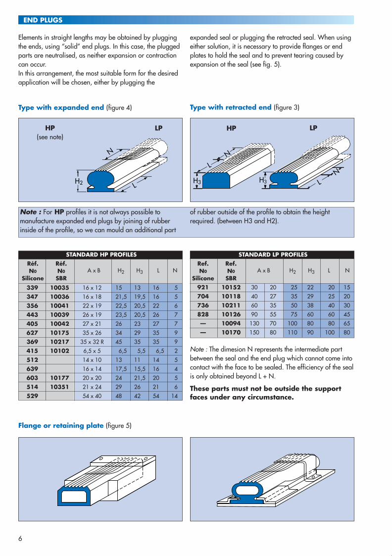
END PLUGS
6
Elements in straight lengths may be obtained by pluggingthe ends, using “solid” end plugs. In this case, the pluggedparts are neutralised, as neither expansion or contractioncan occur.In this arrangement, the most suitable form for the desiredapplication will be chosen, either by plugging the
expanded seal or plugging the retracted seal. When usingeither solution, it is necessary to provide flanges or endplates to hold the seal and to prevent tearing caused byexpansion ot the seal (see fig. 5).
Note : For HP profiles it is not always possible tomanufacture expanded end plugs by joining of rubberinside of the profile, so we can mould an additional part
of rubber outside of the profile to obtain the heightrequired. (between H3 and H2).
H2
N
L
L
H3
N
LN
H3
Type with expanded end (figure 4)
Flange or retaining plate (figure 5)
Type with retracted end (figure 3)
STANDARD HP PROFILESRéf. Réf.N0 N0 A x B H2 H3 L N
Silicone SBR
339 10035 16 x 12 15 13 16 5
347 10036 16 x 18 21,5 19,5 16 5
356 10041 22 x 19 22,5 20,5 22 6
443 10039 26 x 19 23,5 20,5 26 7
405 10042 27 x 21 26 23 27 7
627 10175 35 x 26 34 29 35 9
369 10217 35 x 32 R 45 35 35 9
415 10102 6,5 x 5 6,5 5,5 6,5 2
512 14 x 10 13 11 14 5
639 16 x 14 17,5 15,5 16 4
603 10177 20 x 20 24 21,5 20 5
514 10351 21 x 24 29 26 21 6
529 54 x 40 48 42 54 14
STANDARD LP PROFILESRef. Ref.N0 N0 A x B H2 H3 L N
Silicone SBR921 10152 30 20 25 22 20 15
704 10118 40 27 35 29 25 20
736 10211 60 35 50 38 40 30
828 10126 90 55 75 60 60 45
— 10094 130 70 100 80 80 65
— 10170 150 80 110 90 100 80
Note : The dimesion N represents the intermediate partbetween the seal and the end plug which cannot come intocontact with the face to be sealed. The efficiency of the sealis only obtained beyond L + N.
These parts must not be outside the supportfaces under any circumstance.
HP(see note)
LP LPHP
DEFINITION OF SEAL ACCORDING TO DIRECTION
END PLUGS
Special end plugs : “Expandable”For specific applications required expansion almost all
along the seal we can produce at your request“EXPANDABLE END PLUGS”.
AXIAL EXPANSION (ARRANGEMENT I)The working pressure Pi is normal
INTERNAL RADIAL EXPANSION (ARRANGEMENT II)The working pressure Pi is 20 to 30 % greater than the normal pressure.
EXTERNAL RADIAL EXPANSION (ARRANGEMENT III)The working pressure Pi is normal or 15 to 25 % higher.
A1
J
PiB1
A1 + 1
J/2
0,5
0,5B1
Pi
A1
J
B1
Pi A1
J
B1
Pi
A1 + 1
J/20,5
0,5B1
Pi
J
B1
A1
Pi
The circular arrangements I, II and III are therefore valid for shaped seals provided the radii R,R1 and R2 are adhered to page 4 and 5.
7
Examples :
PLEASE CONSULT OUR TECHNICAL DEPARTMENT
CEFIL'AIR anglais 6/03/03 17:02 Page 12

END PLUGS
6
Elements in straight lengths may be obtained by pluggingthe ends, using “solid” end plugs. In this case, the pluggedparts are neutralised, as neither expansion or contractioncan occur.In this arrangement, the most suitable form for the desiredapplication will be chosen, either by plugging the
expanded seal or plugging the retracted seal. When usingeither solution, it is necessary to provide flanges or endplates to hold the seal and to prevent tearing caused byexpansion ot the seal (see fig. 5).
Note : For HP profiles it is not always possible tomanufacture expanded end plugs by joining of rubberinside of the profile, so we can mould an additional part
of rubber outside of the profile to obtain the heightrequired. (between H3 and H2).
H2
N
L
L
H3
N
LN
H3
Type with expanded end (figure 4)
Flange or retaining plate (figure 5)
Type with retracted end (figure 3)
STANDARD HP PROFILESRéf. Réf.N0 N0 A x B H2 H3 L N
Silicone SBR
339 10035 16 x 12 15 13 16 5
347 10036 16 x 18 21,5 19,5 16 5
356 10041 22 x 19 22,5 20,5 22 6
443 10039 26 x 19 23,5 20,5 26 7
405 10042 27 x 21 26 23 27 7
627 10175 35 x 26 34 29 35 9
369 10217 35 x 32 R 45 35 35 9
415 10102 6,5 x 5 6,5 5,5 6,5 2
512 14 x 10 13 11 14 5
639 16 x 14 17,5 15,5 16 4
603 10177 20 x 20 24 21,5 20 5
514 10351 21 x 24 29 26 21 6
529 54 x 40 48 42 54 14
STANDARD LP PROFILESRef. Ref.N0 N0 A x B H2 H3 L N
Silicone SBR921 10152 30 20 25 22 20 15
704 10118 40 27 35 29 25 20
736 10211 60 35 50 38 40 30
828 10126 90 55 75 60 60 45
— 10094 130 70 100 80 80 65
— 10170 150 80 110 90 100 80
Note : The dimesion N represents the intermediate partbetween the seal and the end plug which cannot come intocontact with the face to be sealed. The efficiency of the sealis only obtained beyond L + N.
These parts must not be outside the supportfaces under any circumstance.
HP(see note)
LP LPHP
DEFINITION OF SEAL ACCORDING TO DIRECTION
END PLUGS
Special end plugs : “Expandable”For specific applications required expansion almost all
along the seal we can produce at your request“EXPANDABLE END PLUGS”.
AXIAL EXPANSION (ARRANGEMENT I)The working pressure Pi is normal
INTERNAL RADIAL EXPANSION (ARRANGEMENT II)The working pressure Pi is 20 to 30 % greater than the normal pressure.
EXTERNAL RADIAL EXPANSION (ARRANGEMENT III)The working pressure Pi is normal or 15 to 25 % higher.
A1
J
PiB1
A1 + 1
J/2
0,5
0,5B1
Pi
A1
J
B1
Pi A1
J
B1
Pi
A1 + 1
J/20,5
0,5B1
Pi
J
B1
A1
Pi
The circular arrangements I, II and III are therefore valid for shaped seals provided the radii R,R1 and R2 are adhered to page 4 and 5.
7
Examples :
PLEASE CONSULT OUR TECHNICAL DEPARTMENT
CEFIL'AIR anglais 6/03/03 17:02 Page 12

Ø E 4 6 8 10 12M M6 M8 M10 M12 M14
Ø J 1,5 3 5 6 6K 12 16 16 20 20
L30/35 30/35/40 40/45/50 40/50/60 50/60/7040/50 50/60 60/70/80 70/80/60 80/90/100
SxR 5x6 6x6 8x8 10x8 11x8M M4 M6 76,5x 0,79 M8 1/8 G M10 1/8 NPT M12 1/4 G M14 M16
Ø J 1,2 3 3 3 5 5 5 6 6 6 815/20/25 15/20/25 20/25/30 15/20/25 20/25/30 20/25/30 20/25/30 20/25/30 20/25/30 30/35/40 40/45/50
L 30/35/40 30/35/40 35/40/50 30/35/40 35/40/50 35/40/50 35/40/50 35/40/50 35/40/50 45/50/60 60/70/8050 50 60 50/60 60/70 60/70 60/70 60/70 60/70 70/80 90/100
SxR 3x4 5x6 6x6 6x8 8x8 8x8 8x8 10x8 10x8 11x8 13x10Ø E 4 6 8 10 12 14 16Ø J 1,5 3,4 3,4 5 6,8 6,8 8,5
15/20/25 15/20/25 20/25/30 25/30/35 30/35/40 35/40/45 45/50/60L 30/40 30/35/40 35/40/50 40/45/50 45/50/60 50/60/70 70/80/90
50 60 70 80M M10 M12 M14
Ø J 3 5 7dxD 4x6 6x8 8x10
L 50/60/70 50/60/70 60/70/8080 90
SxR 8x8 10x8 12x8Ø T1 4 6 8 10 12 14Ø T 4H8 6H8 8H8 10H8 12H8 14H8Ø J 1 1,5 2 4 5 6,8
O ring N°11018 15001 15004 15006 15007 15008
L15/20/25 15/20/25/30 15/20/25/30 20/25/30/35 25/30/35/40 35/40/45/50
30/40 35/40/50 35/40/50 40/45/50/60 45/50/60/70 60/70/80
FITTINGS AND VALVES
Note : RJO fitting can be provided with a locking screw which is perpendicular to the blind hole.In all cases it is necessary to be very careful during assembly because of the O ring (chamfers 30° sharp edges...)
RED elbow fittings and REB fittings can only be fitted to CVL valves.
CVV CVL RED REBNon return valves
yes yes yes no
Ø J Ø E
L
Ø J Ø E
KM
LR
S
flexible tube Ø d x D (not provided)
Ø J
M
R
S
NutL
L
7,65 x 0,79
32
18 90°
7,65
X 0
,79
7,65 X 0,79
25
Ø 6
Ø 12
7,65
X 0
,79
6 x 0,80
L
5,22 x 1,05
Ø J Ø T
Ø T1
L
(housing)
O ring No 30o
REL
Ø J
M
R
S
LREF
REC
REP
RJO
RED REB
CVL 3450
CVV
Our standard fittings and valves are manufacture in brass.
We can also produce fittings in any other material(bronze, stainless steel, etc...)
In addition to standard fittings, we can manufacture anytype of specific fitting to your requirement.For example : armed or wrapped flexible fittings which can
be directly connected to your installation (PLEASECONTACT OUR TECHNICAL DEPARTMENT).
STANDARD FITTINGS
STANDARD VALVES
SPECIAL FITTINGS
L = 34 or 50 mm
L = 29 or 35 mm
8 9
MOULDED CONES
MOULDED CONES (STANDARD SIZES) (1)
hØ nØ mh+1
Ø+1
Housingdetail
Seal detail
Ø 4 4 6 8 10 12 14 16 18
m 6 8 12 14 21 24 26 28 30
n 5 6 10 12 14 16 18 20 22
h 3 4 6 6 10 10 12 12 12
Note : For REC, REF, REP fittings, and CVL and CVV valves consider the size of the thread part (M) as of the connection. In case of intermediate value (inch dimensions) take the next larger cone.(1) (For all other sizes, please contact us).
For a maximum binding (Metal/rubber) “CEFIL’AIR® “
pneumatic seals are equiped with a moulded cone or thefoot of pressure connection according to diameter of these(Fitting or valve).
SURFACE FINISH
The parts of the seals in contact must have a good surfacefinish ; this applies, in particular, to the part to be sealedon the side in contact with the seal.For the grooves, as-rolled sheet is perfectly suitable, butany deposits or scale must be removed. Welds must be made flush. The mean roughness obtained by machining (lathe, mill,
planer, etc.) must not be less than the value of 0,8 to 1,6microns Ra (L.C.A. Rugotest, standard N6 - N7). However,for a unit intended for applications where highperformances will not be required, 3,2 microns Ra will bepermissible (standard N8, L.C.A. Rugotest). Transverse scratches and local damage to the bearingsurfaces to be sealed are prohibited.
PREPARATION OF GROOVES AND CONTACTFACE
Before any operation is performed, a check must be madeto ensure that the groove taking the seal is free fromroughness : grit or weld spatter, flash or projections and
sharp edges. Brushing with a wire brush, followed bydegreasing with a suitable solvent is recommended.
INSTALLATION
1/ - The seal must be absolutely free from internal pressure at the time of fitting. If the valve is equipped withits mechanism, this must be removed throughout the timenecessary for this operation.
2/ - The operation of fitting the seal in the groove must start, without fail, by positioning the pressure connexion(fittings or valve) in the housing, but without fixing itmechanically, as this operation is the last to be done.
3/ In order to fit the seal correctly, it is necessary topressurise it immediately after positioning it in the gluedgroove, while observing the operation recommendations,i.e. perfectly captive on its four faces.
4/ It is possible to leave the “CEFIL’AIR®” seal pressurisedthroughout the time necessary for drying or vulcanizing theadhesives ; it is also possible, after a short drying time, toretract it in order to complete the setting operation.However, it must only be moved after the bond is fixedcompletely.
ASSEMBLY CONDITIONS
Ø
Ø
CEFIL'AIR anglais 6/03/03 17:02 Page 14
10
ASSEMBLY CONDITIONS
FIXING THE SEALS
Although “CEFIL’AIR®” pneumatic HP seals can be fitted ingrooves without any form of retention, it is preferable toglue them to the bottom of the grooves. For this operation,we recommend the use of our general-purpose adhesive“Céfilgrip” which is to be applied directly to the metalwhen it has been thoroughly degreased and is free fromrust or scale.
For arduous uses of silicone “CEFIL’AIR®” pneumatic sealswe recommend to prepare the fixing face by sandblastingand employment of adhesion primer :
Metallic faces 4094 + silicone masticother surfaces MB CAF N° 1
WORKING CONDITIONS
FIXING THE PRESSURE CONNECTION POSITION OF PRESSURE CONNECTION
The housing hole needs to have a conical part according toindications on page 9, to receive the rubber moulded cone of the seal. In the case of threaded connections (REC, REF, REP, CVL and CVV) tightening must be moderate andduring this operation it is absolutely necessary to maintainthe connection to avoid destroying THE ELASTOMER TOMETAL BOND.
“CEFIL’AIR®” pneumatic seals conception requires thatconnections be located at the bottom of grooves or at theend of seals (straight length). When seals have radii curvesit is preferable to avoid connections located in the curvedarea. If the equipment around the seal for assembly orother reasons requires a lateral supply, it is possible to useelbow fittings or special constructions (please consult ourtechnical department).
INTERNAL PRESSURE OF THE SEAL
When free, “CEFIL’AIR®”seals must not besubjected to pressure ≥ 0,8 to1,5 bar(according to the type of profile)..When fitted in a groove, they are perfectly leaktight at aninternal pressure 1,25 to 1,45 times the pressure to seal.
The maximum pressure which the seals can withstanddepends on the clearance between the supporting frameand moving panel (see the tables of profiles pages 4-5).The pressure can be higher when there is very littleclearance.
EXTERNAL PRESSURE AT THE SEAL
“CEFIL’AIR®”seals are designed to provide tightness whenthe enclosure formed is pressurised. In this case, they arestressed by a force which is applied externally to the sealand which tends to force it either towards the outside of thepressurised enclosure or towards the inside of a vacuumenclosure.a) Pressurised enclosuresWith an internal pressure created by gas or a controlledatmosphere, the strength is directly linked to theclearances, deformation of the contact faces and thepressurisation of the seal.
In these applications, it is always necessary to reducedimension “J” to a minimum, restricting the surface towhich the pressure of the enclosure will be applied, in
order to reduce the radial component or, depending on thearrangement, the axial component, as far as possible asthis tends to force the seal outwards.
Generally speaking, the external pressure on the seal “PE”is taken as a radio of 0,7 to 0,8 of the internal pressure“Pi” of the “CEFIL’AIR®” seal, but with the limits laid downin the table concerning profiles (pages 4-5).
b) Vacuum enclosures
The condition of the surfaces in contact, as well as thecompletion of the assembly operation, make it possible for“CEFIL’AIR®”seals to withstand a vacuum of 10-3 Torr(dynamic vacuum).
HP seals must be secured bythe part opposite that of theseal (bottom of grooveonly), avoiding the use ofany adhesives on the lateralparts.
LP seals will preferably befixed mechanically, but, ifan adhesive is necessary,only the fixing heel mustbe used.
( )
HP LP
Gluing areaGluing area
11
TYPES OF ELASTOMERS
“CEFIL’AIR®”pneumatic seals are mainly produced fromelastomers with high mechanical properties : silicone and SBR.
Although these are high performance materials, the mixesare not suitable for all applications, and consequently,other elastomers are also used.
Temp.Elastomers Ref. ∆ Sh range Properties
°C
Styrene - Butadiene
SBR 1 A 60 60 –20+100
Chloroprène (1)4 B61K 60
–20
CR +110
Butyl (1)5 B 60 65
–20
IIR +120
Ethylène Propylène (1) 6 B 65 65 –30
+150EPDM/EPM
SiliconeC 65 M 56
–90
Q+250
Fluorosilicone (1) C 65 M/F 56–65
+200
MFQ
Viton® (1)3 E 65 65
–20
+180
Good resistance to : .- Diluted acides and bases.- Ketones.- Very low permeability.
Good resistance to : - water, steam and atmospheric conditionsLow resistance to hydrocarbon.
(1) Profiles not kept in stock, produced on special request. (Please contact our technical department).
Note : This information represents broad outlines for use.Reservations must be made regarding applicationaccording to temperature, exposure and service life. Due to the relative permeability of elastomers(in contact with air or gas) notably for silicone it is
necessary to provide regulation for this type of inflation. Itis also possible to use other fluids (water, oil ...) toprevent elastomer gas permeability. (Pleasecontact our technical department).
Good resistance to :- Chlorinated solvents.- Aromatics.- Strong acids and bases.
Good resistance to : - Dry and humid heat- Steam P ≤ 6 bars- Cold- Very low oil resistance- Does not age
Ditto Silicone.With good resistance to aromatic hydrocarbons. Chlorinated solvents.
Good resistance to :- water,- demineralised water,- air,- diluted acids and bases,- ketones.Abrasion-resistant.
Ditto SBRBut with better resistance to ultraviolet raysand ozone.Low resistance to grease.
FKM
CEFIL'AIR anglais 6/03/03 17:02 Page 16

12
CALCULATIONS AND SUPPLY
APPLICATION FORCE (CALCULATIONS)
SUPPLY OF MOTIVE FLUID
“CEFIL’AIR®” seals are retracted even with a residualinternal pressure. Their expansion occurs above the latterand brings the contact and sealing face against the movingpart. The pressure necessary for expansion varies a littleover a whole range of arrangements and depending onthe profiles used.In the majority of cases, the minimum operating pressure is1,5 bar ; this corresponds to an application forceproportional to a unit contact surface.
The total applied load “Fj” for the seal on the moving panelwill be determined using the formula :
Fj = (Pi x Kj) x LD
Pi = Internal pressure of the seal in barLD = Expanded length of the seal in cmKj = Coefficient of unit contact surface
Réf. 512 339 347 356 443 405 627 369 415 639 603 514 529 921 704 736 828 10094 10170
Kj 1,0 1,2 1,2 2,0 2,2 2,3 3,0 3,0 0,7 1,2 1,6 1,6 5,0 0,8 1,5 2,5 3,0 4,2 5,0
Pi 4 4 4 6 6 6 8 8 1 5 6 7 10 3 3 3 3 3 3
EXAMPLE OF CALCULATION :
For a ”CEFIL’AIR®” seal with profile N° 347,
“CEFIL’AIR®” pneumatic seals can be supplied either withair or neutral gas and also with water. However, it is necessary to provide a constant supply which
must be guaranteed by pressure regulator to avoidoverpressures.
Fj = (Pi x Kj) x π Ø (1)
= (2 x 1,2) x (3,14 x 150 cm) = 1.130 da.N
12
3
4
5
67
3
3
4
4
5
5
5
1 Air collector.
2 Pressure relief valve filter.
3 Non return valve.
4 Pressure gauge.
5 Valve.
6 Pressure switch.
7 Warning.
If the seals are disconnected from the airsupply source, it is necessary to place ahead loss warning system at the end ofthe seal.
Typical sketch of double cofferdam seal (standard LP).
13
EXAMPLES OF APPLICATION : “Sealing”
MOBILE BULKHEAD SEAL USINGPROFILE REF. 514
STERILISER DOOR SEAL USINGPROFILE REF. 369
NUCLEAR POWER STATIONSEALING DOOR USING PROFILEREF. 10093.
SEAL ON ISOTHERMAL BULKHEAD USING PROFILE REF. 369
SEAL FOR COOLING POND COFFERDAM USING PROFILE REF. 10094.
Technical data and performance claims in our various cataloguescorrespond to current techniques. Under no circumstances do they relievethe user from determining their suitability for a particular application. Our liability is strictly limited to the replacement of goods recognised asbeing faulty (or to a refund at invoiced price without obligation toundertake immediate manufacture of replacement parts).
(1) Øm = mean diameter of seal
mean diameter 1500 mm used withinternal pressurePi = 2 bars
CEFIL'AIR anglais 6/03/03 17:02 Page 18

12
CALCULATIONS AND SUPPLY
APPLICATION FORCE (CALCULATIONS)
SUPPLY OF MOTIVE FLUID
“CEFIL’AIR®” seals are retracted even with a residualinternal pressure. Their expansion occurs above the latterand brings the contact and sealing face against the movingpart. The pressure necessary for expansion varies a littleover a whole range of arrangements and depending onthe profiles used.In the majority of cases, the minimum operating pressure is1,5 bar ; this corresponds to an application forceproportional to a unit contact surface.
The total applied load “Fj” for the seal on the moving panelwill be determined using the formula :
Fj = (Pi x Kj) x LD
Pi = Internal pressure of the seal in barLD = Expanded length of the seal in cmKj = Coefficient of unit contact surface
Réf. 512 339 347 356 443 405 627 369 415 639 603 514 529 921 704 736 828 10094 10170
Kj 1,0 1,2 1,2 2,0 2,2 2,3 3,0 3,0 0,7 1,2 1,6 1,6 5,0 0,8 1,5 2,5 3,0 4,2 5,0
Pi 4 4 4 6 6 6 8 8 1 5 6 7 10 3 3 3 3 3 3
EXAMPLE OF CALCULATION :
For a ”CEFIL’AIR®” seal with profile N° 347,
“CEFIL’AIR®” pneumatic seals can be supplied either withair or neutral gas and also with water. However, it is necessary to provide a constant supply which
must be guaranteed by pressure regulator to avoidoverpressures.
Fj = (Pi x Kj) x π Ø (1)
= (2 x 1,2) x (3,14 x 150 cm) = 1.130 da.N
12
3
4
5
67
3
3
4
4
5
5
5
1 Air collector.
2 Pressure relief valve filter.
3 Non return valve.
4 Pressure gauge.
5 Valve.
6 Pressure switch.
7 Warning.
If the seals are disconnected from the airsupply source, it is necessary to place ahead loss warning system at the end ofthe seal.
Typical sketch of double cofferdam seal (standard LP).
13
EXAMPLES OF APPLICATION : “Sealing”
MOBILE BULKHEAD SEAL USINGPROFILE REF. 514
STERILISER DOOR SEAL USINGPROFILE REF. 369
NUCLEAR POWER STATIONSEALING DOOR USING PROFILEREF. 10093.
SEAL ON ISOTHERMAL BULKHEAD USING PROFILE REF. 369
SEAL FOR COOLING POND COFFERDAM USING PROFILE REF. 10094.
Technical data and performance claims in our various cataloguescorrespond to current techniques. Under no circumstances do they relievethe user from determining their suitability for a particular application. Our liability is strictly limited to the replacement of goods recognised asbeing faulty (or to a refund at invoiced price without obligation toundertake immediate manufacture of replacement parts).
(1) Øm = mean diameter of seal
mean diameter 1500 mm used withinternal pressurePi = 2 bars
CEFIL'AIR anglais 6/03/03 17:02 Page 18

OTHER EXAMPLES OF PROFILES
14
EXAMPLES OF APPLICATIONS : “Handling”
23,5
21
16
16
30
18
35
35
26
20
18
27
TO LIFT TO HOLD
TO CLAMPTO PRESS
2051
372 1406 2239
2190 1856
“CEFIL’AIR®“ pneumatic seals can also be used for the moving, handling, holding or clamping, particularly for fragile orcomplex geometry objects. (see following sketch).
INTRODUCTION
When faced with the problem of sealing between partswhich move in relation to one another and capable ofbeing connected and disconnected at will, the easiest,safest and most effective technique is to use pneumaticseals. “CEFILAIR®” seals, which are expanded and retracted by apneumatic process, have been designed to meet thesemultiple applications. Within the scope of these types of seals, the “CEFILAIR®”,as a result of its patented design employing modern
techniques and the most advanced elastomers, bringswider possibilities of use. As they can satisfy the highest demands of temperaturesfrom - 100°C to + 250/280° C, as well as pressures from10-1 to 10-3 mm Hg to several bar, in the presence of variedatmospheres or fluids, “CEFILAIR®” pneumatic seals can beused in all sectors of industry including advancedtechniques and scientific research.
DESCRIPTION
APPLICATIONS
“CEFILAIR®” pneumatic seals are fitted in the followingcases where sealing, handling, or locking is required :• movable cofferdam bulkheads ;• storage containers ; • transport containers ; • leaktight panels (naval, aerospacial industry) ;• nuclear vessels (equipment or personnel chambers) ;• isothermal chambers ; • clean rooms• sliding or quick-locking doors (autoclaves, sterilisers) ; • centrifugal filters (access doors and drainage hoppers) ;
OPERATION
CEFILAIR® seals have no textile reinforcement or expansionsystem. Their expansion, like their retraction, is obtainedthrough the combined effects of the walls of the sealforming elastic arms.The seals, which are produced from elastomers with a highmodulus of elasticity and considerable elongation andfitted in grooves, are restricted to low work rates, as aresult, they are protected against risks of bursting andtherefore it is necessary to observe the fitting dimensionswithout fail (table, pages 4 - 5).
For specifics uses which need renforced manufacturing (textiles, hight performances aramidfibers) or expanded profiles see pages 14 and 15 and please contact our technical department.
3
MANUFACTURE
“CEFILAIR®” pneumatic seals are produced by joining anextruded or moulded profile. This connection is made byCARBONE LORRAINE, eliminating the need for any excessthicknesses and ensuring perfect continuity while restrictingstresses in the joint as much as possible.
This method provides substantial flexibility with regard tothe geometry of the sections. Two types of standard profilesand a series of different profiles for use in numerousapplications, i.e. sealing, locking or gripping duringautomatic handling have been created.
LPHP
• aircraft access doors ;• cockpit canopies ;• portholes ;• cofferdams ;• pneumatic conveyors (bagging hoppers, valve gates) ;• phonic isolation ;•......
Comment : “CEFILAIR® HP” pneumatic seals must becaptive in slots or grooves closed on all four faces inaccordance with the specified dimensions. You arestrongly recommended not to pressurise or use the sealswhen one of the faces of the groove is open. On the other hand, “CEFILAIR® LP”seals can be secured bytheir base and work freely. However, the maximumpressure cannot be applied until their contact face (toothedside) is against the item to be sealed.
CEFIL'AIR anglais 6/03/03 17:02 Page 8

OTHER EXAMPLES OF PROFILES
OTHER APPLICATIONS
SMALL SIZE SEALS
END PLUGS FOR TUBEExample : “Mechanical expansion”
17,5
14,5
34
25
70
33
60
25
20
20
18
24
58
10266 10410
1263 2104
811
1812
Hole tighteningApplication : Handling hollow pieces(tube, bottle...)
Locking on shaftApplication : Handling of cylindricalpieces
Locking on shaft(cartridge mounting "minimumheight occupied")
Principle Examples :
Ø 23,8
Ø 28,510
Ø 29
M8
34
Ø 27
CONTENTS
DESCRIPTION
STANDARD HP PROFILES
STANDARD LP PROFILES
END PLUG
DEFINITION OF SEAL ACCORDING TO DIRECTION
FITTINGS AND VALVES
MOULED CONES
2
Introduction 3Applications 3Operation 3Manufacture 3
Production 4Assembly 4Curve radii 4
Production 5Assembly 5Curve radii 5
Axial expansion (arrangement I) 7Internal radial expansion (arrangement II) 7External radial expansion (arrangement III) 7
Moulded cones 9
TYPES OF ELASTOMERS
ASSEMBLY CONDITIONSSurface finish 9Preparation of grooves and contact face 9Installation 9Fixing the seals 10Fixing the pressure connection 10Position of pressure connections (valves or fittings) 10
WORKING CONDITIONS
CALCULATIONS AND SUPPLY
EXAMPLES OF APPLICATION “Sealing”
Application force (calculations) 12Supply of motive fluid 12
13
EXAMPLES OF APPLICATION “Handling”14
OTHER PROFILES15
OTHER TYPES OF PRODUCTIONSmall size seals 15Plugs for pipe 15
10
11
Standard fittings 8Standard valves 8
6 - 7
15
CEFIL'AIR anglais 6/03/03 17:02 Page 6

Garlock GmbHPostfach 21 04 64 . Falkenweg 1D-41468 NeussTel. 49-21 31/34 9-0Fax : 49-21 31/349-222e-mail: [email protected]
Garlock (GB) LimitedHambridge Road, NewburyBerkshire RG 14 5 TGEnglandTel. 44-1635-38668Fax : 44-1635-49586
Cefilac90, rue de la Roche du Geai42029 SAINT-ETIENNE Cédex 1FranceTél. 33-4 77 43 51 00 Fax : 33-4 77 43 51 51http://www.helicoflex.com
GarlockSealing Technologies
The most complete line of
And cut gasketsS H E E T S
. . .
GasketsC O N V E N T I O N A L
SealsR E S I L I E N T M E T A L
And assembliesS E A L I N G S Y S T E M S
Seals and ringsG R A P H I T E
And compression packingsB R A I D S
L I P S E A L S A N D O ’ R I N G S
Oil sealsK L O Z U R E
Mechanical seals
SealsE L A S T O M E R
H Y D R A U L I C A N D P N E U M A T I C
Components
G P A - G U L L I V E R
Garlock Inc1666 Division StreetPalmyra, New York 14522Tel. 1-315/597-4811Fax : 1-315/597-3339http://www.garlock-inc.com
O T H E R S E A L I N G P R O D U C T S
AUTHORIZED DISTRIBUTOR
C E F I L ’ A I R ®
ET 5
13E9
930
P. G
uich
ard
& A
ssoc
iés
04
77 8
0 42
14
ET 5
13 E
993
0
GarlockSealing Technologies
Pneumatic seals
CEFIL'AIR anglais 6/03/03 17:02 Page 2