and channel indicator and monitoring unit
TRANSCRIPT
Channel indicator and
monitoring unit
B 70.0202Operating Instructions
2.00/00375947
and

Contents
1 Instrument functions ........................................................................... 3
1.1 Ordering details ...................................................................................................... 3
1.2 Functions of the LMD-96 ....................................................................................... 4
1.3 Functions of the LMD-400 ..................................................................................... 5
2 Operation of the LMD-96 .................................................................... 7
2.1 Displays and controls ............................................................................................ 7
2.2 Normal display ........................................................................................................ 7
2.3 Alarm display .......................................................................................................... 8
2.4 Setting the time ...................................................................................................... 9
2.5 Entering alarm limits and number of channels ................................................... 9
2.6 Installation of a new system ............................................................................... 102.6.1 Extension of an installed system ............................................................................ 112.6.2 Replacing a faulty analogue input module ............................................................. 11
3 Operation of the LMD-400 ................................................................ 13
3.1 Displays and controls .......................................................................................... 13
3.2 Normal display ...................................................................................................... 13
3.3 Alarm display ........................................................................................................ 14
3.4 Alarm print-out ..................................................................................................... 15
3.5 Report print-out .................................................................................................... 15
3.6 Overview of functions .......................................................................................... 16
3.7 Setting the time .................................................................................................... 16
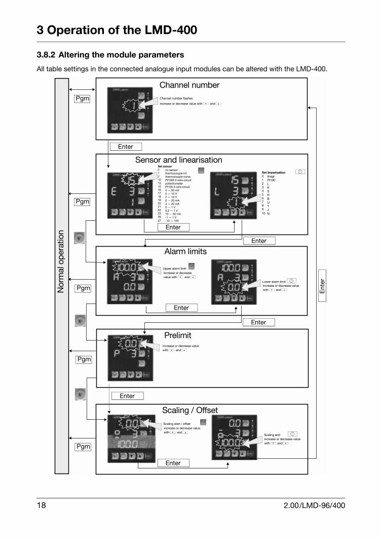
3.8 Configuring the channels .................................................................................... 173.8.1 Factory settings ...................................................................................................... 173.8.2 Altering the module parameters ............................................................................. 18
3.9 Installation of a new system ............................................................................... 193.9.1 Extension of an installed system ............................................................................ 203.9.2 Replacing a faulty analogue input module ............................................................. 20
3.10 De-installation ...................................................................................................... 21
3.11 Configuration ........................................................................................................ 22
4 Electrical connections ...................................................................... 25
4.1 Connection diagram LMD-96 .............................................................................. 25
4.2 Connection diagram LMD-400 ............................................................................ 26
2.00/LMD-96/400

1 Instrument functions
An LMD monitoring system consists of an LMD as the display/control unit and mTRON analogueinput modules. It is possible to cover up to 400 channels and monitor them against limit values.The measurements are shown in three red 4-digit, 7-segment displays, 13 mm high. In normal dis-play, the corresponding channel number is indicated next to the measured value of a channel. The3 or 4 relays and 4 LEDs available in the LMD serve to initiate alarms and signal various systemconditions. The cyclic display can be held on any channel. The measurements can then be manu-ally scrolled by operating the up or down keys. The assignment of the analogue input modules tothe channel numbers takes place at the installation stage.The outstanding features of the system are the simple commissioning of a complete installation,and the convenient configuration and parameter setting. The three red 4-digit, 7-segment displaysand four LEDs give the operator a fast and complete overview of the installation. Data exchange between the modules takes place via the LON bus.
1.1 Ordering details
(1) Basic type
(2) Basic type extensions
(3) Outputs
(4) Supply
Basic type (1) (2) (3) (4)7002 02 / . - . . - 23
Type Code
LMD 96/400 02
Channels Code
96 channels 1
400 channels 2
Relay and analogue output Code
3 relays in the LMD-96 03
4 relays in the LMD-400 04
Rear Code
110 — 240V AC +10/-15%, 48 — 63Hz 23
2.00/LMD-96/400 3
1 Instrument functions
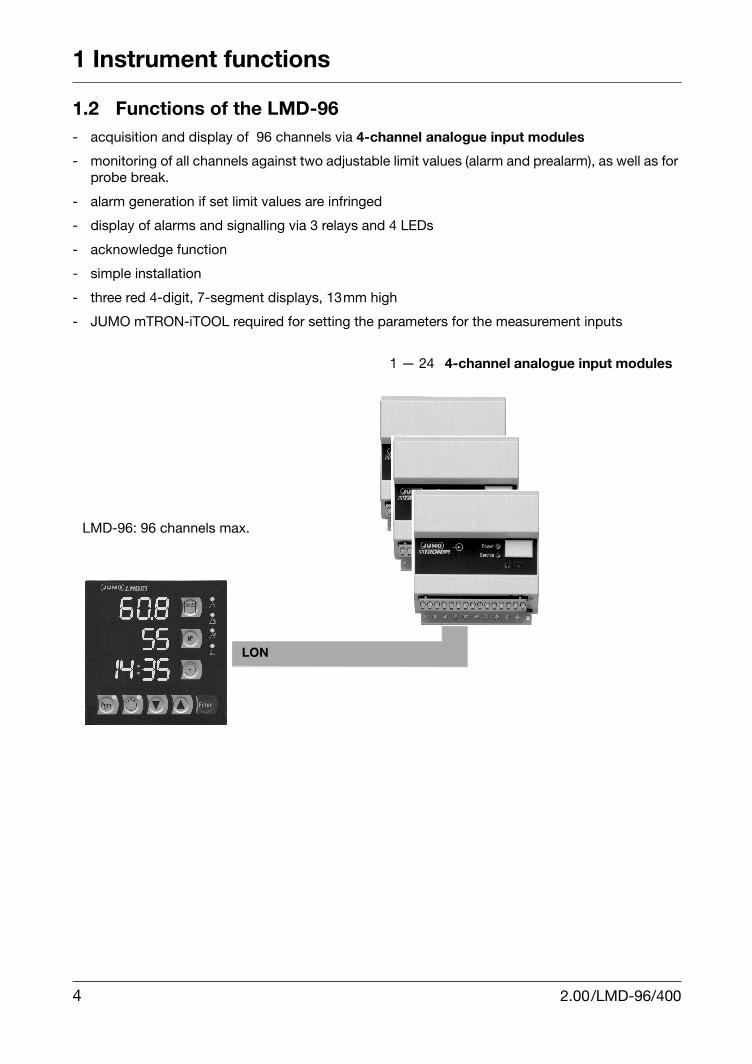
1.2 Functions of the LMD-96- acquisition and display of 96 channels via 4-channel analogue input modules
- monitoring of all channels against two adjustable limit values (alarm and prealarm), as well as for probe break.
- alarm generation if set limit values are infringed
- display of alarms and signalling via 3 relays and 4 LEDs
- acknowledge function
- simple installation
- three red 4-digit, 7-segment displays, 13mm high
- JUMO mTRON-iTOOL required for setting the parameters for the measurement inputs
LMD-96: 96 channels max.
LON
1 — 24 4-channel analogue input modules
4 2.00/LMD-96/400

1 Instrument functions
1.3 Functions of the LMD-400- acquisition of 400 channels via 4- and 8-channel analogue input modules
- monitoring of limit values with window function
- separately adjustable limit values for each channel
- acknowledge function
- simple installation without additional tools
- three red 4-digit, 7-segment displays, 13mm high
- printer connection via communication module to report alarm occurrences andtheir acknowledgement (bus address: 111)
- daily journal print-out of all measured values at a specific time
- signalling of system conditions via 4 relays and 4 LEDs
- linking to SVS-2000 process visualisation software via communication module(bus address: 112)
- complete parameter setting of the analogue inputs
- masking out of individual channels possible
- additional relay output on mTRON relay modules possible (bus address: 110)
LMD-400: 400 channels max. (e.g. 50 x 8 channel analogue input modules)
LON
MO
Db
us
RS
232
2.00/LMD-96/400 5

1 Instrument functions
6 2.00/LMD-96/400

2 Operation of the LMD-96
2.1 Displays and controls
2.2 Normal display
After switch-on the display will automatically be in scroll mode.The LED in the key lights up, i.e. the channel number and therefore also the displayed measu-rement change at 2 second intervals.If the key is pressed, the instrument changes to manual mode. The LED goes dark and therequired channel number can be set with the and keys. In both display modes, newlyoccurring alarms will be displayed immediately.
Normal display Alarm display(immediately on alarmoccurrence)
Probe break or modulefailure
Upperdisplay
measured value (one fixed decimal place)
measured value(one fixed decimal place)
“----”
Middledisplay
channel no.(2-digit, no decimal point)
“A”/“P” and channel no. “A” = alarm, “P” = prealarm
channel no. (2-digit, no decimal point)
Lowerdisplay
current time (hh:mm)
Temperature 1
Temperature 2
Clock
Enter key
Measured value
Channel number
Time
Programming
Automatic operation Decrementing
Incrementing
LED 1LED 2LED 3LED 4
Scroll-Mode(LED an)
Hand-Mode(LED aus)
Scroll mode(LED on)
Manual mode(LED off)
2.00LMD-96/400 7S

2 Operation of the LMD-96
2.3 Alarm display
The desired alarm functions are activated by entering a limit value in place of the “not program-med” entry (“----”).v Section 2.5 “Entering alarm limits and number of channels”
All measurements are cyclically retrieved in turn and compared with the set limit values in theLMD-96. If an infringement is detected, the corresponding alarm is generated.If an alarm occurs, it is displayed immediately. However, in the background, measurements are stillcyclically retrieved and compared with limit values. Further alarms are stored.As well as the alarm displays described above, the system conditions are displayed via 3 relaysand 4 LEDs. The 3 relays operate as break contacts (negative logic).
A genuine alarm must always be acknowledged by , before relay K3 returns to the basicposition. This is also the case if the alarm condition clears before it is acknowledged. The relays,and consequently the LEDs K1 and K2, are only in the alarm condition for as long as the alarm orprealarm is actually present. LED K4 indicates a probe break or bus interruption.
H As long as the number of channels contains the value “0” (when a new instru-ment is switched on), no measurements will be retrieved or displayed.v Section 2.5 “Entering alarm limits and number of channels”
H When an installed system is switched on, it takes 20 seconds before valid mea-surements are available. During this time, the first two displays will be switchedoff.
Basic position Prealarm Alarm Probe break
Relay 1 active inactive active active
Relay 2 active active inactive active
Relay 3 active active toggle operation, whenever unacknowledged alarms are waiting
active
LED 1 off on off off
LED 2 off off on off
LED 3 off off flashes, whenever unacknowledged alarms are waiting
off
LED 4 off off off on
8 2.00/LMD-96/400

2 Operation of the LMD-96
2.4 Setting the timeThe time can be set in either manual or scroll mode. Input of the time can be ended at any time bypressing the clock key.The instrument returns automatically to normal display.
h Press the key
h Set the day (upper display) using the and keys
h Confirm with
h Set the month (middle display) using the and keys
h Confirm with
h Set the year (lower display) using the and keys
h Confirm with
h Set the hours using the and keys
h Confirm with
h Enter the minutes and set using the and keys
h Confirm with
2.5 Entering alarm limits and number of channels
h Press the key
h Change the value which is currently flashing using the and keys
Manualmode
Display 2:alarm limit value
Display 1:prealarm limit value
Display 3:number ofchannels
Pgm
ENTER
ENTER
ENTER
Parameter levelPgm LED on
Normal displayPgm LED offScroll
mode
Temp1
Temp2
Clock
2.00/LMD-96/400 9

2 Operation of the LMD-96
Range of values:
- limit value for prealarm -250 to+ 850°C (Temp1 key)
- limit value for alarm -250 to +850°C (Temp2 key)
- channel number 1 — 96 (Clock key)
h Confirm the entered value with
h When all parameters are confirmed, leave the parameter level again, using the key.
2.6 Installation of a new system
The installation can be completed without any additional aid.
h Wire up the modules in accordance with the connection diagram
The following installation procedure fixes the module number and consequently the channelnumber for all analogue input modules (module no. 1: channels 1 — 4, module no. 2: channels5 — 8, etc...).
h Press + (“1” flashes in the middle display)
h Press the installation key (4) on the module using a ball-pen or pencil.After a successful installation, the value in the middle display increases.
h Repeat the procedure until all modules are installed
h End the installation with +
h Adjust the number of channels
v Section 2.5 “Entering alarm limits and number of channels”
10 2.00/LMD-96/400
2 Operation of the LMD-96
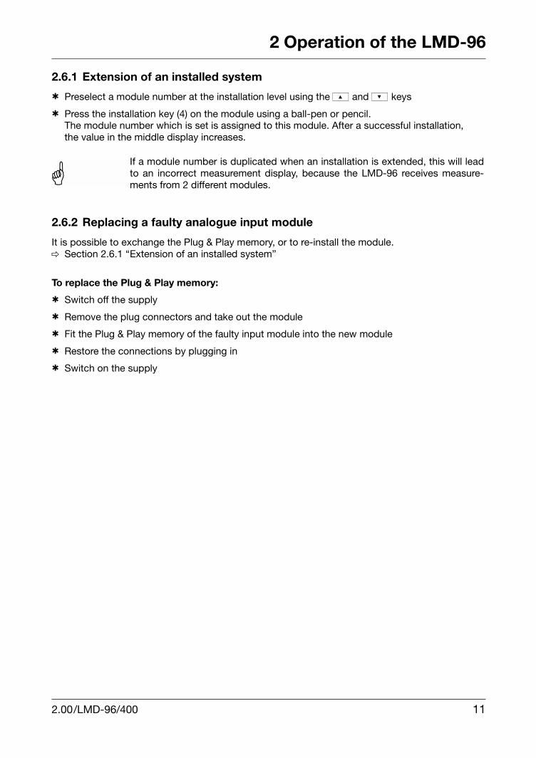
2.6.1 Extension of an installed system
h Preselect a module number at the installation level using the and keys
h Press the installation key (4) on the module using a ball-pen or pencil.The module number which is set is assigned to this module. After a successful installation,the value in the middle display increases.
2.6.2 Replacing a faulty analogue input module
It is possible to exchange the Plug & Play memory, or to re-install the module.v Section 2.6.1 “Extension of an installed system”
To replace the Plug & Play memory:
h Switch off the supply
h Remove the plug connectors and take out the module
h Fit the Plug & Play memory of the faulty input module into the new module
h Restore the connections by plugging in
h Switch on the supply
AIf a module number is duplicated when an installation is extended, this will leadto an incorrect measurement display, because the LMD-96 receives measure-ments from 2 different modules.
2.00/LMD-96/400 11

2 Operation of the LMD-96
12 2.00/LMD-96/400

3 Operation of the LMD-400
3.1 Displays and controls
3.2 Normal display
After switch-on, the display will automatically be in scroll mode (LED in the auto key lights up), i.e.the channel number, and therefore also the displayed measurement, change at the set scroll rate.v Section 3.11 “Configuration” Cd 02
Normal display Alarm display(on alarm occurrence)
Probe break ormodule failure
Upperdisplay
measured value (one decimal place)
measured value(one decimal place)
“----”
Middledisplay
channel no. (3-digit, no decimal point)
“A” = alarm (Cd 05=1)“P” = prealarm (Cd 05=1)“O” = overrange (Cd 05=0)“U” = underrange (Cd 05=0)and channel number
channel no. (3-digit, no decimal point)
Lowerdisplay
display of the alarm limit value (one decimal place) or key: the current time appears for 5 seconds
Key 1
Key 2
Clock key
Enter key
Measured value
Channel number
Alarmlimit value
Programming
Automatic operation Decrementing
Incrementing
LED 1LED 2LED 3LED 4
2.00/LMD-96/400 13

3 Operation of the LMD-400
If the key is pressed, the instrument changes to manual mode. The LED goes dark and the re-quired channel number can be set with the und keys. In both display modes, newlyoccurring alarms will be displayed immediately.
v Section 3.11 “Configuration”
3.3 Alarm display
When an LMD-400 is installed, monitoring of the measurements against alarm limits takes place inthe analogue input modules. However, the alarm limits as well as other parameters can be chan-ged.v Section 3.8.2 “Altering the module parameters”
As well as the measurements, the alarm conditions of the input modules are retrieved in a cyclicalsequence. If an alarm occurs, the LMD-400 automatically changes to the channel which has initia-ted the alarm. Further alarms are stored. In addition, the system conditions are displayed via 4 re-lays and 4 LEDs.The 4 relays operate as break contacts (negative logic)
An alarm must always be acknowledged with before relay 3 returns to the normal position.This is also the case if the alarm condition clears before it is acknowledged. The relays, and conse-
H The number of channels is factory-set to “0”. Measurements will only be retrieved anddisplayed when this is changed to a different value.
H When an installed system is switched on, it takes 60 seconds before valid measure-ments are available. During this period the lower display will show the current time.
Normal display Lower limitunderrange
Prealarm Upper limitoverrange
Probe breakor businterruption
Relay 1 active inactive inactive active active
Relay 2 active active active inactive active
Relay 3 active switches on and off in time with the flashing pulses of the LED
switches on and off in time with the flashing pulses of the LED
Relay 4 active active active active inactive
LED 1 off on on off off
LED 2 off off off on off
LED 3 off flashes, whenever unacknowledged alarms are waiting
off flashes, whenever unacknowledged alarms are waiting
off
LED 4 off off off off on
Scroll-Mode(LED an)
Hand-Mode(LED aus)
Scroll mode(LED on)
Manual mode(LED off)
14 2.00/LMD-96/400
3 Operation of the LMD-400
quently the LEDs 1 and 2, are in the alarm condition only for as long as the alarm or prealarm is ac-tually present. LED 4 indicates a probe break or bus interruption.
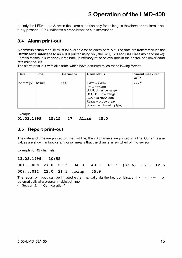
3.4 Alarm print-out
A communication module must be available for an alarm print-out. The data are transmitted via theRS232 serial interface to an ASCII printer, using only the RxD, TxD and GND lines (no handshake).For this reason, a sufficiently large backup memory must be available in the printer, or a lower baudrate must be set. The alarm print-out with all alarms which have occurred takes the following format:
Example:01.03.1999 15:15 27 Alarm 45.0
3.5 Report print-out
The date and time are printed on the first line, then 8 channels are printed in a line. Current alarmvalues are shown in brackets. “noinp” means that the channel is switched off (no sensor).
Example for 12 channels:
13.03.1999 10:55
001...008 27.0 23.5 66.3 48.9 66.3 (33.6) 66.3 12.5
009...012 22.0 21.3 noinp 55.9
The report print-out can be initiated either manually via the key combination + , orautomatically at a programmable set time.v Section 3.11 “Configuration”
Date Time Channel no. Alarm status current measured value
dd.mm.yy hh:mm XXX Alarm = alarmPre = prealarmUUUUU = underrangeOOOOO = overrangeACK = acknowledgeRange = probe breakBus = module not replying
YYY.Y
2.00/LMD-96/400 15

3 Operation of the LMD-400
3.6 Overview of functions
3.7 Setting the time
The time can be set in either manual or scroll mode. Input of the time can be ended at any time bypressing the clock key.The instrument returns automatically to normal display.
h Press the clock key twice
h Set the day (upper display) using the and keys
h Confirm with
h Set the month (middle display) using the and keys
h Confirm with
h Set the year (lower display) using the and keys
h Confirm with
h Set the hours using the and keys
h Confirm with
h Enter the minutes and set using the and keys
h Confirm with
uuuScroll-Mode(LED an)
Hand-Mode(LED aus)
Uhr
Uhr
Up-Enter Pgm
Pgm-Up
Pgm-Up
Report-ausdruck
Parameter-ebene
Uhrzeitstellen
Installation
Konfiguration
5 Sek.aktuelleUhrzeit
ConfigurationSet time
5 seccurrenttime
Reportprint-out
Clock
Clock
Parameterlevel
Scroll mode(LED on)
Manual mode(LED off)
16 2.00/LMD-96/400

3 Operation of the LMD-400
3.8 Configuring the channels
3.8.1 Factory settings
Analogue input module, 4-channel Analogue input module, 8-channel
Sensor 0 — 400 Ω according to version
Linearisation Pt100 Pt100
Scaling start 0 0
Scaling end 100 100
Lower limit 0 -50
Upper limit 100 +50
Prealarm limit 0 0
2.00/LMD-96/400 17
3 Operation of the LMD-400
3.8.2 Altering the module parameters
All table settings in the connected analogue input modules can be altered with the LMD-400.
18 2.00/LMD-96/400

3 Operation of the LMD-400
3.9 Installation of a new systemNo further aids are required for the installation.Altogether up to 400 channels of analogue input modules can be covered, and in addition 1 relaymodule and 2 communication modules can be connected.
h Wire up the modules according to the connection diagram
The following installation procedure fixes the module number and consequently the channelnumber for all analogue input modules (module no. 1: channels 1 — 4, module no. 2: channels5 — 8, etc...).
h Press + (“1” flashes in the middle display)
h Press the installation key (4) on the module with a ball-pen or pencil
The middle display is counted up, if an analogue input module was installed.The lower display will show an r, P or b, depending on the type of module which is currentlyinstalled.
h When all connected modules have been identified, end the installation with +
h Adjust the number of channels
v Section 3.11 “Configuration”
H If only one communication module is to be used as the MODbus interface for the su-pervisory level, Cd14 must be reset to MODbus protocol at the configuration level.Instead of the “P” for printer, a “b” is then displayed during the installation.
appears after key (4) on the relay module was pressed.Address:110
appears after key (4) on the first communi-cation module was pressed for the printer connection.Address: 111
appears after key (4) on the second communication module was pressed for the supervisory level.Address: 112
2.00/LMD-96/400 19

3 Operation of the LMD-400
3.9.1 Extension of an installed system
h Preselect a module number in the installation level using the and keys
h Press the installation key (4) on the module with a ball-pen or pencilThe module number set is assigned to this module. After a successful installation, the valuein the middle display increases.
3.9.2 Replacing a faulty analogue input module
It is possible to exchange the Plug & Play memory or to re-install the module.v Section 3.9.1 “Extension of an installed system”
To replace the Plug & Play memory:
h Switch off the supply
h Remove the plug connector and take out the module
h Fit the Plug & Play memory of the faulty input module into the new module
h Restore the connections by plugging in
h Switch on the supply
AIf a module number is duplicated when a system is extended, this will lead to anincorrect measurement display, because the LMD-400 receives measurementsfrom 2 different modules.
20 2.00/LMD-96/400

3 Operation of the LMD-400
3.10 De-installationIf any previously installed communication modules or the relay module are no longer required, theycan be taken out of the system again.
h Press and
h Press the key repeatedly, until the module letter to be removed flashes
h Press The module letter disappears from the display and is consequently removed from the system.
h Remove further modules with and , if required
h End the de-installation with and
H The N° key takes you back to the installation level.v Section 3.9 “Installation of a new system”
H The configuration level is accessed automatically.
2.00/LMD-96/400 21
3 Operation of the LMD-400
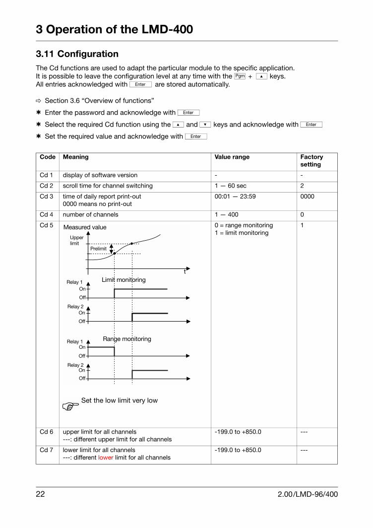
3.11 ConfigurationThe Cd functions are used to adapt the particular module to the specific application. It is possible to leave the configuration level at any time with the + keys.All entries acknowledged with are stored automatically.
v Section 3.6 “Overview of functions”
h Enter the password and acknowledge with
h Select the required Cd function using the and keys and acknowledge with
h Set the required value and acknowledge with
Code Meaning Value range Factorysetting
Cd 1 display of software version - -
Cd 2 scroll time for channel switching 1 — 60 sec 2
Cd 3 time of daily report print-out0000 means no print-out
00:01 — 23:59 0000
Cd 4 number of channels 1 — 400 0
Cd 5 0 = range monitoring1 = limit monitoring
1
Cd 6 upper limit for all channels ---: different upper limit for all channels
-199.0 to +850.0 ---
Cd 7 lower limit for all channels ---: different lower limit for all channels
-199.0 to +850.0 ---
HSet the low limit very low
22 2.00/LMD-96/400

3 Operation of the LMD-400
h End the configuration with +
Cd 8 differential for prealarm---: value is to be entered for each channel
-199.0 to +850.0 ---
Cd 9 with “linear” linearisation, this is the display value for start of the standard signal rangewith all other linearisations:offset for all channels---: value is to be entered for each channel
-199.0 to +850.0 ---
Cd 10 display value for end of the standard signal/ resistance thermometer range--: value is to be entered for each channel
-199.0 to +850.0 ---
Cd 11 password setting 0 — 99 0
Cd 12 baud rate 2 = 12003 = 24004 = 48005 = 96006 = 192007 = 38400
5
Cd 13 parity 0 = none1 = even2 = odd
0
Cd 14 switching between printer operation or MODbus protocol for supervisory level
0 = printer operation1 = MODbus
-
2.00/LMD-96/400 23

3 Operation of the LMD-400
24 2.00/LMD-96/400
4 Electrical connections
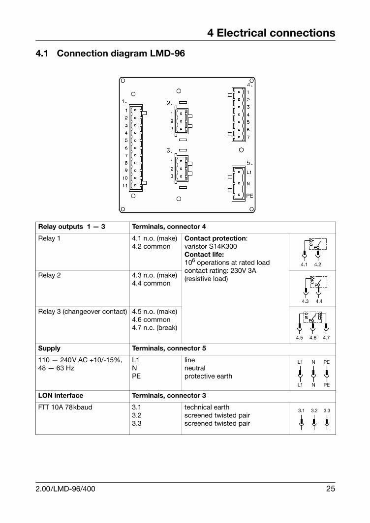
4.1 Connection diagram LMD-96
Relay outputs 1 — 3 Terminals, connector 4
Relay 1 4.1 n.o. (make)4.2 common
Contact protection:varistor S14K300Contact life:106 operations at rated loadcontact rating: 230V 3A (resistive load)Relay 2 4.3 n.o. (make)
4.4 common
Relay 3 (changeover contact) 4.5 n.o. (make)4.6 common4.7 n.c. (break)
Supply Terminals, connector 5
110 — 240V AC +10/-15%, 48 — 63 Hz
L1NPE
lineneutralprotective earth
LON interface Terminals, connector 3
FTT 10A 78kbaud 3.13.23.3
technical earthscreened twisted pairscreened twisted pair
2.00/LMD-96/400 25

4 Electrical connections
4.2 Connection diagram LMD-400
Relay outputs 1 — 4 Terminals, connectors 4 and 2
Relay 1 4.1 n.o. (make)4.2 common
Contact protection:varistor S14K300Contact life:106 operations at rated loadcontact rating: 230V 3A (resistive load)Relay 2 4.3 n.o. (make)
4.4 common
Relay 3 (changeover contact) 4.5 n.o. (make)4.6 common4.7 n.c. (break)
Relay 4 (changeover contact) 2.1 n.o. (make)2.2 common2.3 n.c. (break)
Supply Terminals, connector 5
110 — 240 V AC, +10/-15%, 48 — 63 Hz
L1NPE
lineneutralprotective earth
LON interface Terminals, connector 3
FTT 10A 78kbaud 3.13.23.3
technical earthscreened twisted pairscreened twisted pair
26 2.00/LMD-96/400

4 Electrical connections
2.00/LMD-96/400 27

M. K. JUCHHEIM GmbH & CoHausadresse:Moltkestraße 13 - 31, 36039 Fulda,GermanyLieferadresse:Mackenrodtstraße 14, 36039 Fulda,GermanyPostadresse:36035 Fulda, GermanyTelefon: (06 61) 60 03-0Telefax: (06 61) 60 03-5 00E-Mail: [email protected]: www.jumo.de
United Kingdom
JUMO Instrument Co. Ltd.Temple Bank, RiverwayGB-Harlow,Essex CM20 2TTPhone (0 12 79) 63 55 33Fax (0 12 79) 63 52 62
USA
JUMO PROCESS CONTROL INC.735 Fox Chase,Coatesville, PA 19320
Phone 610-380-8002, 800-554 JUMOFax 610-380-8009