and setup connections - bell customer support...
TRANSCRIPT
Page 12-1
HOW TO CONNECT YOUR SATELLITE RECEIVERDo you have a handful of cables and a head full of questions? This chapter is the perfectplace to find out how to connect the receiver to all kinds of equipment. You’ll find thischapter particularly helpful if you decide to move your receiver or if you get a new TV,VCR, or DVD player.
• CONNECTING TO THE NEARBY TV (TV1)
• CONNECTING TO THE REMOTE TVS (TV1 OR TV2)
• CONNECTING TO YOUR DISH ANTENNA
• CONNECTING THE PHONE LINE
• CONNECTING A VCR TO THE REMOTE TV
• CONNECTING OFF-AIR ANTENNA
• USING TROUBLESHOOTING TOOLS
Connectionsand Setup��
9242_14_Ch12_eng 6/11/07 9:36 AM Page 1

Page 12-2
User Guide
CONNECTING TO THE NEARBY TV (TV1)This section describes how to connect receiver TV1 output ports to a nearby TV. Selectone of the following methods.
HDTV DIGITAL AUDIO/VIDEO CONNECTIONS
The HDTV Digital Audio/Video connection provides high-quality audio and video toyour HDTV or HD Monitor in one cable.
1. Connect an HDTV Digital Audio/Video cable between the HDTV DigitalAudio/Video connection on the receiver and HDTV set or monitor.
2. Turn on your receiver and TV using the front panel buttons.
3. Confirm that you are getting a picture from the receiver. Consult your HDTV user’sguide if you need to change your HDTV to display from the Digital Audio/Videoinput.
4. If you do not see a picture, see No Picture on the nearby TV on page 12-3.
Note: In most cases connecting the Digital Audio/Video cable will provide plug-and-play control of the monitor’s display resolution and other settings. However, your HDTV may require selecting a different format to display from thereceiver during setup.
5. Turn up the volume on your HDTV and confirm you have sound. If you don’t havesound, your system may require you to connect audio (red and white) RCA-typecables between the receiver Audio Outputs and audio input connections.
9242_14_Ch12_eng 6/11/07 9:36 AM Page 2

Page 12-3
��
YPBPR CONNECTIONS
The YPbPr connections provide high-quality video to your HDTV or HD monitor.
1. Connect between the YPbPr component connections on the receiver and the nearbyTV using component video cables.
2. Connect audio (red and white) RCA-type cables between the receiver Audio Outputsand audio input connections that go with the YPbPr connectors on your HDTV ormonitor.
3. If you do not see a picture, change the resolution setting on the receiver.
4. Turn up the volume on your HDTV and confirm you have sound. Check the RCA-type connections if you don’t have sound.
NO PICTURE ON THE NEARBY TV
This section will help you make a picture on the nearby TV in the event that you couldnot do so in the previous sections.
1. Connect RCA-type cable connections between the receiver TV1 Out and the nearby TV.
2. Make sure the receiver and nearby TV are on.
3. Make sure the nearby TV is set to use the RCA-type inputs. Look on the back of yourHDTV and consult your HDTV user’s guide.
4. Change the HDTV settings as described on page 12-4.
5. Switch to the nearby TV to display from the HD inputs you select in the previoussections. If you have a picture from TV1, you are finished.
6. Repeat steps 4 and 5 until the nearby TV displays video from the receiver.
Connections and SetupConnecting To The Nearby TV (TV1)
9242_14_Ch12_eng 6/11/07 9:36 AM Page 3

Page 12-4
User Guide
SETTING UP TO DISPLAY IN HD
Once the receiver has been activated with qualifying Bell ExpressVu programming, youwill be able to receive HD programs to watch. Use the following steps to select thedesired HDTV format.
1. Consult your HDTV user’s guide for the HD format resolution that the TV supports(1080i or 720p).
2. Press MENU, select System Setup, and then HDTV Setup to open the receiver HDTVSetup screen.
3. Select the HD format settings (Analog Type and TV Type) that matches the formatyour TV supports.
4. While in this menu, select the Aspect Ratio option that matches your TV:
• 16x9 is the setting for wide screen HDTV display.
• 4x3 #1 is the setting to use on a 4x3 TV which uses vertical compression. Whenfed with a 16x9 program, a compatible TV automatically makes the pictureletterbox format (black bars top and bottom), to preserve the correct horizontal andvertical proportions.
• 4x3 #2 is the setting to use on a 4x3 TV which does NOT have internal verticalcompression. When fed with a 16x9 program, such a TV will not show black barsat the top and bottom, and the picture will appear tall and skinny.
5. Press Done.
6. If required, set up the HDTV to display in the format you desire. Some HDTVs willautomatically adjust to the resolution setting of the receiver.
9242_14_Ch12_eng 6/11/07 9:36 AM Page 4

Page 12-5
��
CONNECTING TO THE REMOTE TVS (TV1 OR TV2)This section describes how to connect the receiver CH 21–69 Out connection to thecableready remote TV located in another room away from the receiver. You can use theseinstructions to connect TVs in your house to see programming from TV1 or TV2. Thisinstallation uses your in-home cable system. If your house does not have built-in cabling,it will be necessary to run cables from the receiver to each remote TV. Due to thedifficulty of this installation, you should consider having this professionally installed.Call Bell ExpressVu at 1-888-SKY-DISH.
CONNECTING OTHER TV(S) (TV1 OR TV2)
An in-line coaxial attenuator has been included with your receiver and may need to beinstalled using the following guidance:
• If connecting to your in-home cabling system to distribute the signal to a TV(s) inother rooms, in most cases you will not have to install the attenuator on the CH 21–69port for typical in-home cabling systems.
• If connecting directly to a nearby TV tuner port, you must install the attenuator in thecable between the CH 21–69 Out port and the TV tuner.
If you have an off-air antenna or cable connected to your in-home cablesystem, see Connecting Off-Air Antenna following this section.
Make sure you are familiar with how to change channels on your TV and ifnecessary how to switch your TV between off-air and cable channels.During this procedure, it will be necessary to change thechannels on your TV(s) to tune to these channels to see the video from thereceiver. See your TV user’s guide for instructions.
1. Connect the tuner input of the remote TV(s) in other rooms to an existing wall cableoutlet using a coaxial cable.
2. Turn on every remote TV connected to the in-home cabling system.
3. Find three channels next to each other on one of your remote TVs that do not pick up any signals from off-air or cable broadcasts (they should show nothing but snow or static).These channels must fall in one of the two ranges below. For example, if you find thatcable channels 75, 76, and 77 do not pickup any broadcasts, pick these channels sincethey fall into the range below for cable channels. Make sure these three channels onother remote TVs also do not pick up broadcasts.
• Air Mode - Select a channel between 21 and 69 if your TV(s) will be set in Air Mode.
• Cable Mode - Select a channel between 73 and 125 if your TV(s) will be set inCable Mode.
Connections and SetupConnecting To The Remote TVs (TV1 or TV2)
9242_14_Ch12_eng 6/11/07 9:36 AM Page 5

Page 12-6
User Guide
Note: The remote TV(s) will have to be set to the same channel mode, either off-airor cable channel mode for this installation. See your TV user’s guide for instructionson how to set your TV to off-air or cable channel modes.
4. Pick the channel in the middle of the three you selected in step 3. Write that channeldown in the blank provided in step 5. For example, if the three channels you picked inthe preceding step were air channels 60, 61, and 62, pick channel 61 and write it inspace provided step 5.
5. If your TV is in off-air mode for the channels you picked in step 4, circle “Air” below.If your TV is in cable mode for the channels you picked in step 4, circle “Cable”below. If you are using these instructions for TV1 and TV2, pick different channels(for example, Channel 60 for TV1 and Channel 64 for TV2).
TV1 Channel:____________ TV2 Channel:____________ Air/Cable
6. Set all of your remote TV(s) to the channel mode (Air or Cable) you wrote in step 5.
7. Tune all of your remote TV(s) to the channel(s) you wrote in step 5. This is thechannel you will use to receive your satellite programming.
8. Connect CH 21-69 Out on the receiver to your existing wall cable outlet using acoaxial cable.
Note: If you do not have an existing in-home cable system, you will need to runcoaxial cable to each TV in other rooms. If this is too difficult, you may want tocontact a professional to do this installation.
9. Turn on the nearby TV (the TV that gets programming from the TV1 outputs).
10. Make sure the receiver's green TV1 indicator is on.
11. Press MENU. Select System Setup, Installation, and then Modulator Setup.
12. With the Modulator Setup screen displayed on the nearby TV, use Remote Control 1to do the following:
a Under TV2 Out (or TV1 Out), select either Air (for off-air channel numbers) orCable (for cable channel numbers) based on what you wrote down in step 5.
b Under TV2 Out (or TV1 Out), use the UP and DOWN ARROWS to change themodulator channel to the one you wrote in step 5.
c Select Done.Note for TV1 Out: If you locked the receiver, a message will display asking youto enter your password.
13. For some TVs, you must run a channel scan so that the TVs will find and display theselected channel from the receiver. Run channel scan on all remote TV(s), if available.See your TV user’s guide for instructions.
9242_14_Ch12_eng 6/11/07 9:36 AM Page 6

Page 12-7
��
14. Confirm that you see a picture from the receiver on your remote TV(s).
• If your picture looks good, go to step 23.
• If your TV(s) do not have a picture or if it is not as clear as you would like it to be,go to the next step.
15. You may need to change the cable connection on the splitter that sends the TV signalthroughout your house. The change that needs to be made is move the cable comingfrom the receiver CH 21-69 Out from the output of the splitter to the input of thesplitter using the instructions that follow.
The following figure shows an example of what your splitter may look like. Yoursplitter may look different. The places where the splitter indicates Out refers to allTVs connected to your cable system. The places where the splitter indicates In refersto where the TV signal is fed into the splitter.
16. Find where the TV signal is distributed throughout your house. It should be nearwhere the cable TV service enters the house.
17. Disconnect the cable TV service cable or antenna cable from the splitter input, ifnecessary. Make sure the disconnected cable is capped or otherwise protected fromthe weather.
18. Disconnect the cable coming from the receiver CH 21–69 Out port from the splitter. Ifyou do not know which cable this is, go to the next step. Otherwise, go to step 21.
19. If you have multiple TVs on the cable system, do the following to determine whichcable on the splitter is coming from the receiver:
• If you have at least some picture on your TV(s), turn on all remote TVs connectedto the cable system. Disconnect and reconnect each cable one by one observingwhat happens to the TV(s). When all remote TVs lose the signal, you havedisconnected the receiver’s cable. If only some or one TV loses the signal, thenyou have disconnected a cable from the TV(s).
Connections and SetupConnecting To The Remote TVs (TV1 or TV2)
9242_14_Ch12_eng 6/11/07 9:36 AM Page 7

Page 12-8
User Guide
• If the above step does not work, disconnect one of the output cables and connect tothe splitter input. If you do not see a picture, connect the cable back to its output.Repeat this step on every connection until you get a picture on the remote TV(s).
20. Reconnect the receiver’s cable to the input of the splitter.
21. Make sure you have a good picture on your remote TV(s).
22. Confirm Remote Control 2 (or Remote Control 1 with a Green UHF Pro key, soldseparately) controls the receiver. See page 10-3 for instructions.
23. Program Remote Control 2’s (or Remote Control 1 with a Green UHF Pro key, sold separately) RECOVER to the channel you selected in step 5. See page 10-14 for instructions.
9242_14_Ch12_eng 6/11/07 9:36 AM Page 8
Page 12-9
��
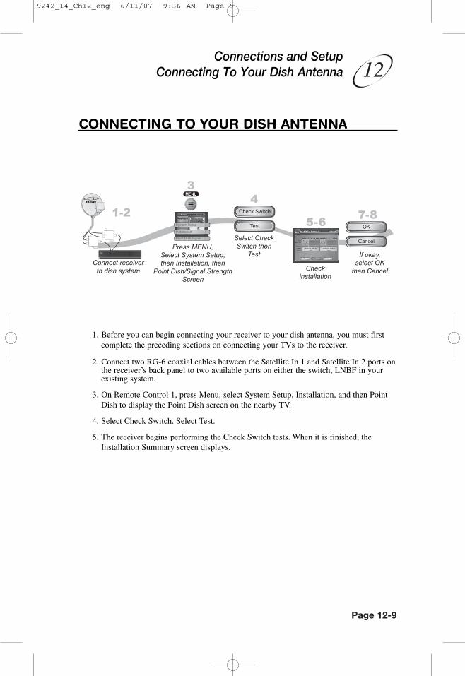
CONNECTING TO YOUR DISH ANTENNA
1. Before you can begin connecting your receiver to your dish antenna, you must firstcomplete the preceding sections on connecting your TVs to the receiver.
2. Connect two RG-6 coaxial cables between the Satellite In 1 and Satellite In 2 ports onthe receiver’s back panel to two available ports on either the switch, LNBF in yourexisting system.
3. On Remote Control 1, press Menu, select System Setup, Installation, and then PointDish to display the Point Dish screen on the nearby TV.
4. Select Check Switch. Select Test.
5. The receiver begins performing the Check Switch tests. When it is finished, theInstallation Summary screen displays.
Connections and SetupConnecting To Your Dish Antenna
9242_14_Ch12_eng 6/11/07 9:36 AM Page 9

Page 12-10
User Guide
6. Make sure that the information on the Installation Summary screen identifies yoursystem correctly and shows all transponders for all satellites in your system.
7. Select OK to go to the Point Dish/Signal screen.
8. Select Cancel to exit the Point Dish menu. At this point, the receiver may walk youthrough a procedure to download software. If this prompt displays, follow theinstructions and do not disturb the receiver until the nearby TV is displaying BellExpressVu video. Otherwise, press VIEW LIVE TV. After a few minutes, you shouldbe watching TV.
CONNECTING THE PHONE LINEYou must keep the receiver connected to an active telephone line to order Pay-Per-Viewprograms, use all of the Interactive features, or other services from Bell ExpressVu withyour remote control.
Note: You may be able to use a wireless modem jack. However, this may not support allthe features of this receiver, such as Caller ID.
Note: If you have a Digital Subscriber Line (DSL), you may have to install a DSL filterbetween the receiver’s back panel Phone Jack and the telephone wall jack to successfullyconnect with Bell ExpressVu. You can obtain a filter from your DSL provider.
PHONE LINE CONNECTION
Run a telephone cable with a standard RJ-11 connector from the receiver’s back panelPhone Jack to an active telephone connection.
9242_14_Ch12_eng 6/11/07 9:36 AM Page 10

Page 12-11
��
PHONE SYSTEM SETUP
You must also set up the receiver for your telephone system (touch tone or rotary), andset a telephone number prefix, if you need a prefix to make an outside call.
1. Pressing MENU, then select System Setup, Installation, and then Phone System.
2. Select the Touch Tone or the Rotary Phone option in the Phone Type list.
3. Select either the No Prefix or the Prefix Code option in the Outside Line Prefix list.
Note: Usually, you need a telephone number prefix only for business installations.For most residential installations, all you need to do is set the telephone system type.The default setting of No Prefix will allow correct dialing. If this is the case, select theSave option to save the above setting, and stop here. If you do need to set a prefix,then instead of selecting the Save option, go on to step 5.
4. If you selected No Prefix, select Done.
5. If you selected Prefix Code, the receiver highlights the box where you must enter theexact sequence you dial the phone to obtain an outside line.
6. Select Done.
Connections and SetupConnecting The Phone Line
9242_14_Ch12_eng 6/11/07 9:36 AM Page 11

User Guide
CONNECTING A VCR TO THE REMOTE TVThe diagram below provides example of how to connect VCRs to your satellite TVsystem.
For this installation, always leave your VCR powered on so that the TV canreceive satellite programming. If you turn off your VCR, your TV will notbe tuned to the correct channel to receive satellite programming.
Note: Connecting your TV directly to the satellite receiver provides the best audio andvideo quality.
1. Connect the tuner input of the remote VCR to an existing wall cable outlet using acoaxial cable.
2. Connect a coaxial cable from the output on the VCR to the remote TV’s tuner port.
3. Plug in and turn on the remote VCR and TV.
4. Tune the remote VCR to the remote TV channel that you use to watch satellite TVprogramming (for example, channel 60) as set on page 12-6.
5. Set the VCR output to channel 3 or 4.
6. Tune the remote TV to the same channel that you set your VCR to in step 6.
Page 12-12
9242_14_Ch12_eng 6/11/07 9:36 AM Page 12

Page 12-13
��
CONNECTING OFF-AIR ANTENNAIf you want to receive channels from an off-air antenna or cable in addition to yoursatellite receiver programming, connect the off-air antenna/cable into your TVdistribution equipment.
• The 8VSB TV Antenna/Cable In on your receiver's back panel can be used to receiveand view programming on the nearby TV from an off-air antenna or cable service.
• Connect a VHF/UHF off-air antenna to the 8VSB TV Antenna/Cable port.
• Not all off-air broadcasts can be recorded with your receiver.
• The remote TV can view to off-air channels only in Single Mode.
• For remote TVs receiving programming from CH 21-69 Out, the off-air antenna needsto be connected to your TV distribution equipment. TV distribution equipment devicesinclude coax panels, amplifiers or super home nodes, and are available through manycompanies.
• You can add local off-air channels and assign them network affiliations. Once youhave done this, you can access the channels via the Program Guide or the BrowseBanner in much the same way as you would satellite channels.
Note: The type of antenna required depends on the channels used by, and the locationsof, the local broadcasters for your area. Visit www.antennaweb.org or contact aprofessional installer to help you select a suitable antenna.
Make sure to follow the antenna installation instructions correctly. Groundan outdoor antenna per the National Electrical Code (NEC) and any localelectrical codes.
The audio/video quality on local off-air channels depends on the distanceand terrain between the broadcast station and your home, and on theplacement and quality of the off-air TV antenna you use. If you havequestions about offair channels, contact the broadcaster, not BellExpressVu.
Connections and SetupConnecting Off-Air Antenna
9242_14_Ch12_eng 6/11/07 9:36 AM Page 13

Page 12-14
User Guide
SCANNING FOR OFF-AIR CHANNELS
With your off-air antenna adjusted for best reception, use these instructions to scan foroffair channels for the nearby TV.
1. Make sure you have your off-air antenna connected to the receiver’s 8VSB TVAntenna/ Cable connection.
2. Press MENU, select System Setup, and then Local Channels to open the LocalChannels screen. If this is the first time you have opened this screen, it will have nochannels listed.
3. Scan for channels by selecting Scan Locals. When the Local Channels screendisplays, select Yes.
4. The scan will take a few minutes to complete. When it finishes, the results will showhow many channels the scan found.
5. Select OK to go back to the Local Channels screen.
Note: If the channel number says None, you have not yet assigned this channel anetwork affiliation or name. The Arrow at the bottom left means that there are morechannels, off the bottom of the screen, which you can get to with the ARROW keys ifyou wish to edit their names or remove them.
6. If you want to name the off-air channels, continue on. If you do not want to nameyour offair channels, select Done. You will then be taken out of the menus back towatching TV.
7. Select a channel and then select Edit Name to modify the way the channel namedisplays on your screen.
9242_14_Ch12_eng 6/11/07 9:36 AM Page 14

Page 12-15
��
8. Use the virtual keyboard on the screen to select the letters of your channel name.
9. When you are finished making changes, select Done.
PEAKING YOUR OFF-AIR ANTENNA
1. Press MENU, select System Setup, and then Local Channels to open the LocalChannels screen.
2. Highlight the Channel field and use the UP and DOWN ARROWS to select a digitaloff-air channel. Make sure you see a green signal strength bar and a Locked indicationon the meter.
3. Adjust the orientation of your antenna to maximize the signal strength. If you cannotget a Locked indication, you may need to upgrade your antenna or relocate it to abetter position.
Connections and SetupConnecting Off-Air Antenna
9242_14_Ch12_eng 6/11/07 9:36 AM Page 15

Page 12-16
User Guide
ABOUT OFF-AIR TV BROADCASTS
Off-air TV signals are broadcast from stations on the ground, while satellite TV signalsare broadcast from satellites in space. You receive off-air TV signals using an indoor oroutdoor antenna instead of the satellite dish. You are likely familiar with analog off-airTV signals - these are the signals that have been used to broadcast TV for many years.New digital off-air TV signals are broadcast and received in the same way. Digital off-airTV broadcasting uses advanced technology like that of the Bell ExpressVu to deliversuperb picture quality and CD quality sound. However, digital off-air signal reception(like analog off-air signal reception) depends on several things:
• The distance between the broadcast station and your home (the farther away thestation, the weaker the signal);
• The broadcast station's power (the lower the power, the weaker the signal);
• Obstacles between the station and your home, such as mountains, buildings, trees, orother objects (these may block or reflect the signal before it reaches you);
• Multiple broadcast stations (to receive good signals from several stations, you mayneed to compromise in how you aim the antenna or you may need more than oneantenna).
The effects of poor digital reception are different from the effects of poor analogreception::
• Poor analog reception usually causes the TV picture to be “snowy” or to include“ghosts,” that is, multiple images caused by receiving reflected signals along with thedirect signal from a station.
• Poor digital reception may cause the TV picture to be “pixelized,” that is, broken upinto small squares of various colours, or to be lost completely (the TV screen is allblack or all blue).
• Digital broadcasts often provide either a very good picture or no picture at all.
• You may be able to receive a poor analog signal but not be able to receive a digitalsignal at all.
To get the best possible digital signal reception, make sure you use the best off-airantenna for where you live:
• You can receive a limited number of channels using a rabbit ears type antenna on topof the TV set, or a much larger number via a large UHF/VHF indoor/outdoor antenna.
• The higher the quality of the antenna you use, the greater its range and the better itsreception will be.
9242_14_Ch12_eng 6/11/07 9:36 AM Page 16
Page 12-17
��
The Consumer Electronics Association maintains a website, www.antennaweb.org, thatyou can visit for help in choosing an antenna.You may want to contact a professional TVantenna installer for advice or help in choosing, installing, and aiming an antenna. Keepin mind, digital off-air TV broadcasting is in its infancy. So, digital off-air service maybe interrupted because:
• Broadcasters are testing digital signals, and may stop broadcasting without notice.
• Many broadcasters do not yet have permanent broadcast stations and may beoperating at less than full power.
• Broadcasters are not legally required to provide full-time digital signals for several years.
• Some digital channels do not broadcast all the time.
If you have questions about off-air channels, contact the broadcasters, not BellExpressVu. Bell ExpressVu does not broadcast off-air signals and so cannot do anythingto change offair signal quality. However, the receiver's digital channel setup menusprovide a signal strength bar that can help you in aiming the off-air TV antenna for thestrongest possible signal.
Here’s something interesting! We all know that there’s no Channel 1, but did you know that no TV stations broadcast on Channel 37? That channel is reserved for radio astronomy. Perhaps someday we will receive TV shows fromAlpha Centauri.
Connections and SetupConnecting Off-Air Antenna
9242_14_Ch12_eng 6/11/07 9:36 AM Page 17
Page 12-18
User Guide
USING TROUBLESHOOTING TOOLSYour receiver has troubleshooting tools that a Customer Service Representative may askyou to use if you should ever run into problems while using your equipment. Eventhough these tools are quite helpful, it is recommended that you only use them when onthe phone with a Bell ExpressVu representative.
RESETTING YOUR RECEIVER
Reset your receiver as directed by the Customer Service Representative as follows:
1. Press and hold the front panel POWER until only the green TV1 indicator is lit.
2. Let go of the front panel POWER.
It will take a few minutes for your receiver to reset and come back on. When you resetyour receiver, your receiver may have to download an updated Program Guide. If thisis the case, it may take longer for the receiver to come back on.
DIAGNOSTICS
The Customer Service Representative may ask you to open the Diagnostics screen.Remember to have an active phone line connected to your receiver.
1. Press MENU, select System Setup, and then select Diagnostics. The Diagnosticsscreen shows you various tests the Customer Service Representative may ask you toperform on your receiver:
• Connection - Tests for a valid receiver phone connection.
• Dial Out - If “No Dial Out Pending” is displayed, the receiver does not need tohave its smart card records updated.
• Counters - Shows you a list of diagnostic counters. Use PAGE UP and PAGEDOWN to scroll through the list of counters displayed.
2. Select Done.
9242_14_Ch12_eng 6/11/07 9:36 AM Page 18
Page 12-19
��
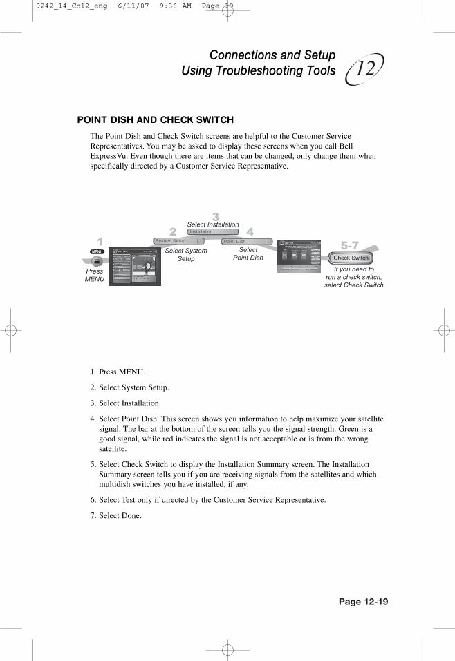
POINT DISH AND CHECK SWITCH
The Point Dish and Check Switch screens are helpful to the Customer ServiceRepresentatives. You may be asked to display these screens when you call BellExpressVu. Even though there are items that can be changed, only change them whenspecifically directed by a Customer Service Representative.
1. Press MENU.
2. Select System Setup.
3. Select Installation.
4. Select Point Dish. This screen shows you information to help maximize your satellitesignal. The bar at the bottom of the screen tells you the signal strength. Green is agood signal, while red indicates the signal is not acceptable or is from the wrongsatellite.
5. Select Check Switch to display the Installation Summary screen. The InstallationSummary screen tells you if you are receiving signals from the satellites and whichmultidish switches you have installed, if any.
6. Select Test only if directed by the Customer Service Representative.
7. Select Done.
Connections and SetupUsing Troubleshooting Tools
9242_14_Ch12_eng 6/11/07 9:36 AM Page 19

Page 12-20
User Guide
Notes
9242_14_Ch12_eng 6/11/07 9:36 AM Page 20