animating 2d characters for - pdf.ebook777.compdf.ebook777.com/069/9781305501843.pdf · with office...
TRANSCRIPT


Animating 2DCharacters for
Games in Blender™
Alan Thorn
Cengage Learning PTR

Animating 2D Characters for Games inBlender™Alan Thorn
Publisher and General Manager,Cengage Learning PTR: Stacy L. Hiquet
Associate Director of Marketing:Sarah Panella
Manager of Editorial Services:Heather Talbot
Senior Product Manager: Emi Smith
Project Editor: Kate Shoup
Technical Reviewer: Michael Duggan
Copy Editor: Kate Shoup
Interior Layout Tech: MPS Limited
Cover Designer: Mike Tanamachi
Proofreader: Kelly Talbot EditingServices
© 2015 Cengage Learning PTR.
CENGAGE and CENGAGE LEARNING are registered trademarks of CengageLearning, Inc., within the United States and certain other jurisdictions.
ALL RIGHTS RESERVED. No part of this work covered by the copyrightherein may be reproduced, transmitted, stored, or used in any form or by anymeans graphic, electronic, or mechanical, including but not limited tophotocopying, recording, scanning, digitizing, taping, Web distribution,information networks, or information storage and retrieval systems, exceptas permitted under Section 107 or 108 of the 1976 United States CopyrightAct, without the prior written permission of the publisher.
For product information and technology assistance, contact us atCengage Learning Customer & Sales Support, 1-800-354-9706.
For permission to use material from this text or product,submit all requests online at cengage.com/permissions.
Further permissions questions can be emailed [email protected].
Blender is a trademark of The Blender Foundation. All other trademarks arethe property of their respective owners.
All images © Cengage Learning unless otherwise noted.
ISBN-13: 978-1-305-50184-3
ISBN-10: 1-305-50184-5
Cengage Learning PTR
20 Channel Center Street
Boston, MA 02210
USA
Cengage Learning is a leading provider of customized learning solutionswith office locations around the globe, including Singapore, the UnitedKingdom, Australia, Mexico, Brazil, and Japan. Locate your local office at:international.cengage.com/region.
Cengage Learning products are represented in Canada by NelsonEducation, Ltd.
For your lifelong learning solutions, visit cengageptr.com.
Visit our corporate website at cengage.com.
eISBN-10: 1-305-50184-5

Acknowledgments
Writing a book is no simple matter. Although I’m listed as the author, this book wouldnot have been possible without the valuable help and fine work of many people, includingEmi Smith, Kate Shoup, Michael Duggan, and many others. I’d like to say a big thank youto them, and also to you, the reader, for investing time to improve your skills. I hope thisbook proves helpful to you.
Alan Thorn, 2014
London
iii

About the Author
Alan Thorn is a game developer, freelance programmer, and author with more than13 years of industry experience. He founded Wax Lyrical Games in 2010 and is the creatorof the award-winning game Baron Wittard: Nemesis of Ragnarok. He is the author of10 video training courses and 11 books on game development, including Unity 4 Funda-mentals, UDK Game Development, and Pro Unity Game Development with C#. He is also avisiting lecturer for the game development master’s degree at the National Film andTelevision School, London. Alan has worked on a freelance basis on more than 500 pro-jects, including games, simulators, kiosks, serious games, and augmented reality softwarefor game studios, museums, and theme parks worldwide. He is currently working on anadventure game, Mega Bad Code, for desktop computers and mobile devices.
iv

Contents
Introduction
Chapter 1 Preparation and ModelingStep 1: Drawing Your Character
Step 2: Importing Character References into Blender
Step 3: Modeling from References
Step 4: Optimizing Topology for Games and Animation
Step 5: Housekeeping
Conclusion
Chapter 2 UV Mapping and TexturingStep 6: Removing Doubles
Step 7: Creating the Character Atlas Texture
Step 8: UV Preparation and Projection
Step 9: Creating UV Islands and Mapping
Step 10: Completing the Mapping
Conclusion
Chapter 3 Rigging, Bones, and WeightsStep 11: Creating Armatures
Step 12: Creating Bones
Step 13: Skinning
Step 14: Adjusting the Weighting
v

Step 15: Applying Inverse Kinematics
Conclusion
Chapter 4 AnimationStep 16: Preparing for Animation
Step 17: Blocking In the Walk Cycle
The Contact Pose
The Passing Pose
The Down Pose
The Up Pose
Step 18: Moving the Arms
Conclusion
Chapter 5 Exporting and TestingStep 19: Exporting Objects from Blender
Step 20: Importing Objects into Unity
Step 21: Configuring the Mesh
Step 22: Testing the Mesh
Conclusion
vi Contents
Introduction
This eBook is aimed at readers looking to use Blender to create animated 2D charactersfor video games. It’ll be especially relevant to developers working with Unity, as I provideexamples for importing characters into Unity. The main focus of this eBook, however,is on Blender’s tools and techniques for animating a 2D character through a completelooping walk cycle animation. It covers subjects such as modeling from reference, texturemapping and unwrapping, rigging, animation, and finally export-import workflows. Fur-ther, it outlines the basic mechanical stages of a walk cycle, which apply to most bipedalcharacters.
In describing this eBook, it’s important to stress several issues:
n This eBook covers Blender, which is freely available software. It doesn’t coveralternatives such as 3DS Max or Maya. This, however, doesn’t mean the generalworkflow and concepts covered here don’t apply to those applications, because theydo. It means only that all software-specific steps will be given in relation to Blenderand its UI.
n This eBook focuses on 2D characters as opposed to the more common 3D type.Consequently, this eBook is especially relevant for developers creating cartoon orstylized characters for their games.
n In covering character animation, this eBook assumes you have a working familiaritywith the Blender basics such as the UI, a control scheme, and a solid grasp offoundational concepts like box modeling, mesh editing, and object transforming.This eBook avoids unnecessary assumptions where possible, introducing concepts
vii

and tools as though you were encountering them for the first time, but it doesn’tassume you’re totally new to Blender.
Tip
If you’ve never used Blender before, or if you’re new to 3D modeling generally, I recommend checking outmany of the books and tutorials on the Blender basics before getting started with this eBook. Good startingpoints include The Complete Guide to Blender Graphics by John M. Blain and Blender Foundations by RolandHess.
With those points in mind, let’s get started animating 2D characters with Blender!
viii Introduction

Chapter 1
Preparation and Modeling
Blender is renowned for creating 3D graphics and animation—the kind found in real-time3D games and movie shorts like The Elephant’s Dream and Big Buck Bunny. For this rea-son, 2D character animation—the kind found in cartoons—may be regarded as an uncon-ventional use of Blender. Indeed, many avoid Blender altogether for this sort ofanimation. They often turn instead to Adobe Flash, Toon Boom Animate, Anime StudioPro, or Synfig Studio. But this eBook will show you how to creatively adapt and reuseBlender’s 3D functionality to make professional-grade 2D character animation forgames. Being able to do this is useful. It means Blender users can continue to use theirfree and cross-platform software and its familiar toolset to get their versatile work done.This can save time, effort, and money.
This eBook is project-based. It focuses on the specific, real-world case of creating a fullyanimated character in Blender that can walk in a loopable cycle, as shown in Figure 1.1.You’ll work through the complete animation process, from start to end—from drawingboard to a final game-ready model.
The character to be created is named Pendragon, a carefree, clumsy homicide detective inmy upcoming game Mega Bad Code. One of Pendragon’s main design qualities is to pro-vide comic relief for a dark and brooding storyline. In creating Pendragon, however, it’simportant to be aware of the wider context and applicability of the knowledge containedhere. Certainly, in finishing this eBook and using the companion files, you’ll re-create theanimated Pendragon character. But you’ll have achieved much more than this—you’llhave seen a complete animation toolset in Blender and gained first-hand experience of
1
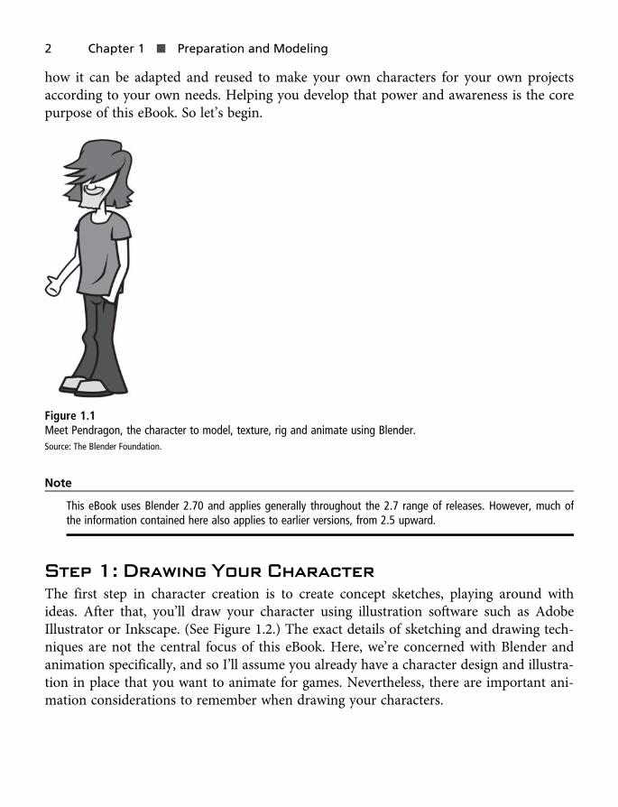
how it can be adapted and reused to make your own characters for your own projectsaccording to your own needs. Helping you develop that power and awareness is the corepurpose of this eBook. So let’s begin.
Figure 1.1Meet Pendragon, the character to model, texture, rig and animate using Blender.Source: The Blender Foundation.
Note
This eBook uses Blender 2.70 and applies generally throughout the 2.7 range of releases. However, much ofthe information contained here also applies to earlier versions, from 2.5 upward.
Step 1: Drawing Your CharacterThe first step in character creation is to create concept sketches, playing around withideas. After that, you’ll draw your character using illustration software such as AdobeIllustrator or Inkscape. (See Figure 1.2.) The exact details of sketching and drawing tech-niques are not the central focus of this eBook. Here, we’re concerned with Blender andanimation specifically, and so I’ll assume you already have a character design and illustra-tion in place that you want to animate for games. Nevertheless, there are important ani-mation considerations to remember when drawing your characters.
2 Chapter 1 n Preparation and Modeling

Note
You can create 2D characters using a range of software. Some free solutions include Inkscape (http://www.inkscape.org), GIMP (http://www.gimp.org/), MyPaint (http://mypaint.intilinux.com/), and Krita (https://krita.org/).
Figure 1.2Start by drawing and inking your character. Arrange your character so that each limb or element is separate.Source: The Inkscape Project.
Specifically, before drawing your final character, you’ll want to be sure to identify all ormost of the final animations you’ll need: walk cycles, runs, jumps, punches, and more.Work out which limbs on the body must move (translate, rotate, and scale) to accommo-date all your animation needs. Typically, these will be arms, legs, body, and head, butother character designs could involve more elements including costume props (such ashats) and weapons (for example, rifles and swords).
After identifying all movable things in the design, create your character in software so thateach separate limb or element can easily be saved to an independent image file. To achievethis, simply draw each element in a separate layer or group that can be shown or hiddenindividually. The Pendragon character created here will walk. To achieve this, you’ll needto be able to move his legs, head, body, and arms. These limbs have been drawn on sepa-rate layers in Inkscape, as shown in Figure 1.2, and each element has been exported to a
Step 1: Drawing Your Character 3

separate image file (using File > Export Bitmap), as shown in Figure 1.3. These images willbe imported into Blender shortly as reference material.
Figure 1.3Each animated element is separated into a unique image file. The Pendragon files include head, left arm, right arm,left leg, right leg, torso, neck, and back hair.Source: The Inkscape Project.
Note
The Pendragon element files are included in the eBook companion files in the Chapter01 folder.
Notice from Figure 1.3 that each element is divided into a separate file based on whether itmoves independently during the animation, as well as its depth order in the overall com-position. For example, the arms will swing and bend separately from the body and legsand other limbs, so they should be exported to separate images. That’s to be expected.But the back hair is also exported as a separate image even though it’ll move along withthe rest of the head as it rotates. The back hair is not exported with the head because itappears behind the elongated neck, and both the neck and head can rotate separatelyaround their own pivot points.
4 Chapter 1 n Preparation and Modeling

Step 2: Importing Character Referencesinto BlenderIf you’ve separated your character elements into separate images, then you’re ready tostart creating an animated character in Blender. The basic process is to import yourcharacter images into Blender and then to model from them as references, as shown inFigure 1.4. Let’s see how this works in more detail, starting from an empty scene file.
Figure 1.4Modeling a character from reference in Blender.Source: The Blender Foundation.
1. Switch to a front orthographic viewport in Blender (press Ctrl+1 using the Mayakeys). This gives you a precise 2D view of the scene.
2. Create a new empty object at the origin. To do so, switch to the Create tab and clickthe Empty button. (See Figure 1.5.) This object will become your image reference, asyou’ll see. If the plane axes are not aligned to the front view, be sure to select theAlign to View checkbox in the Create panel found in the bottom-left corner of thescreen.
Step 2: Importing Character References into Blender 5
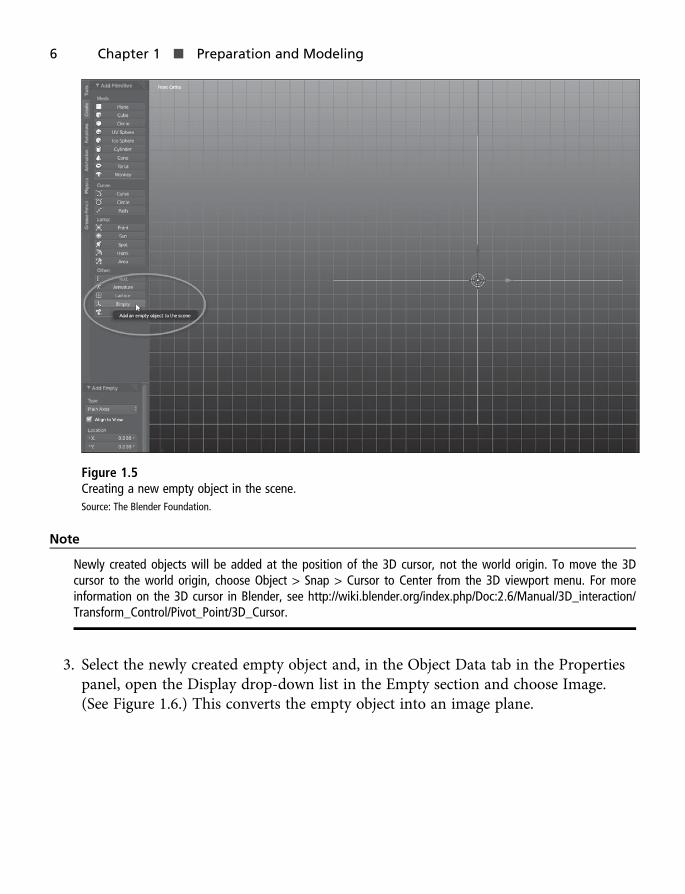
Figure 1.5Creating a new empty object in the scene.Source: The Blender Foundation.
Note
Newly created objects will be added at the position of the 3D cursor, not the world origin. To move the 3Dcursor to the world origin, choose Object > Snap > Cursor to Center from the 3D viewport menu. For moreinformation on the 3D cursor in Blender, see http://wiki.blender.org/index.php/Doc:2.6/Manual/3D_interaction/Transform_Control/Pivot_Point/3D_Cursor.
3. Select the newly created empty object and, in the Object Data tab in the Propertiespanel, open the Display drop-down list in the Empty section and choose Image.(See Figure 1.6.) This converts the empty object into an image plane.
6 Chapter 1 n Preparation and Modeling

Figure 1.6Converting an empty objects into an image plane.Source: The Blender Foundation.
4. The image begins empty. The next step is to load a reference image into it. Toachieve this, click the Open button in the Properties panel and select one of thecharacter limb reference images from your hard drive. I’ve started with the head, asshown in Figure 1.7. The reference image should appear in the viewport.
Step 2: Importing Character References into Blender 7

Figure 1.7Loading a reference image into the viewport.Source: The Blender Foundation.
5. When a reference is loaded, reduce its transparency to around 0.5 in the Propertiespanel. This weakens its visual intensity in the scene, enabling you to concentrate onmodeling.
6. In the Outliner window, disable object selection for the reference. This prevents youfrom accidentally selecting and moving it. To do so, click the mouse pointer icon inthe Outliner to toggle it off for the reference object. See Figure 1.8.
8 Chapter 1 n Preparation and Modeling

Figure 1.8Adjusting reference transparency and selectability.Source: The Blender Foundation.
7. Repeat this process for each successive reference image for your character untilall references are loaded into the scene. You can show and hide each referenceindividually by toggling its visibility from the Outliner using the eye icon. (SeeFigure 1.9.) This enables you to isolate and view only the reference you need at anyone time in the viewport.
Step 2: Importing Character References into Blender 9

Figure 1.9Loading all your reference images into Blender.Source: The Blender Foundation.
Step 3: Modeling from ReferencesThe loaded reference images will act only as guides for creating polygonal models thattruly conform to the reference. When creating a 2D character for animation, the modelingprocess involves shaping a flat-plane primitive to the reference image using standardmodeling techniques like extrude and subdivide, as shown in Figure 1.10. This modelingapproach may seem like overkill, but typically it’s necessary.
10 Chapter 1 n Preparation and Modeling

Figure 1.10Generate a plane and model over the reference image.Source: The Blender Foundation.
Note
It might seem that a simpler solution would be to use only quad objects (planes with four corner vertices)—tomap the reference images as textures onto the quads, using a transparent background in the texture to hideany pixels that are not part of the character. That way, you could stick with quad meshes and wouldn’t needto add additional vertices. But quads usually fail to deform and bend as intended when animated, causingunwanted distortions on your character. So it’s often best to avoid using quads.
1. Model each limb or element one at a time, hiding and showing the references in theviewport as necessary. To begin, create a new and separate mesh for each element.I often start with the character’s head element. Center the head reference in the frontviewport, and then create a new plane object in the scene using the Create panel.(See Figure 1.11.)
Step 3: Modeling from References 11

Figure 1.11The modeling process often begins with a flat plane object.Source: The Blender Foundation.
Note
Be sure to model your 2D characters inside orthographic viewports, such as a front, top, or side view, asopposed to a perspective view. This helps your vertices stay within the same XY plane.
2. Newly created objects like planes and cubes may appear in a solid or textureddisplay in the viewport, covering or concealing the reference image behind them.It’s important to see both your model and reference at the same time, however. Forthis reason, choose Wireframe from the Viewport Shading menu, as shown inFigure 1.12. This renders your plane object as a wireframe or cage while stillshowing the image reference.
12 Chapter 1 n Preparation and Modeling

Figure 1.12Use Wireframe mode to view your meshes and references together.Source: The Blender Foundation.
3. To start the modeling process, shape the plane object to the general extents of thereference image, encompassing its total surface area. To do this, enter Edit mode forthe mesh object (press the Tab key) and then translate the mesh vertices into place.If your character is in the cartoon style and has a thick, stroked outer border, likePendragon, then position your vertices to the outside edge of the border, allowingas much of the reference image to be contained inside the mesh as possible. SeeFigure 1.13.
Step 3: Modeling from References 13

Figure 1.13Building the extents of the mesh using the image reference.Source: The Blender Foundation.
4. A quad mesh is not detailed enough to approximate the overall shape of the head.Neither will it be enough for nearly any element of a character. For this reason, moredetail must be added to the mesh. You achieve this by using the Loop Cut and Slidetool, available from the Tools panel only while in Edit mode. After you click the LoopCut and Slide tool button, move your cursor over the mesh. Blender will display apreview for a new edge loop that’ll be inserted into the mesh. Click your mouse to fixthe new edge loop at the previewed position and then press Enter to confirm theoperation, adding in more detail. (See Figure 1.14.)
14 Chapter 1 n Preparation and Modeling

Figure 1.14The Loop Cut and Slide tool lets you insert additional detail into a model for shaping and finalizing.Source: The Blender Foundation.
5. Continue to use the Loop Cut and Slide tool to insert more edge loops horizontallyacross the model, shaping and positioning each vertex as you go in line with thereference image. (See Figure 1.15.) At the end of the process, you should have a meshthat closely matches the reference except for vertical detail. I typically add verticaldetail in a second pass. Remember to keep vertices positioned at the outer extremesof the reference while maintaining the shape and profile of the reference as closelyas possible.
Step 3: Modeling from References 15

Figure 1.15Insert additional edge loops to approximate horizontal detail in the mesh.Source: The Blender Foundation.
6. Because you’re modeling for games, it’s important to be aware of your model’s vertexand face counts. You may be working within specific limits set by your team or youmay simply be keeping vertices as low as possible, within reasonable limits, to respectyour ultimate creative vision. To view the vertex and face counts for the selectedmesh in Blender, see the Information panel, which appears at the top of the screen bydefault. (See Figure 1.16.)
Figure 1.16Viewing vertex and face counts for the selected mesh.Source: The Blender Foundation.
16 Chapter 1 n Preparation and Modeling

7. For a second pass, use the Loop Cut and Slide tool to insert additional vertical edgeloops downward through the mesh, again shaping and positioning vertices to matchthe reference. Use the vertices to shape the top and bottom of the Pendragon head.When modeling, try to keep vertices and faces roughly equal in size and distanceapart, conforming to the general shape and flow of the reference. This will ensure thebest results when creating animations later. (See Figure 1.17.)
Figure 1.17Inserting vertical edge loops to shape the head.Source: The Blender Foundation.
8. Repeat this process for all other limbs and elements in the character, making sure touse a separate mesh for each. Use the hiding and showing feature for objects in theOutliner so you can concentrate on just one object at a time.
Step 3: Modeling from References 17

Step 4: Optimizing Topology for Games and AnimationWhen modeling for games generally, and also for 2D characters, you should use only tri-angles or quads—that is, three- or four-sided polygons. (See Figure 1.18.) Polygons withmore than four sides, known as n-gons, typically do not render correctly when importedinto game engines. If you stick to using plane objects and the Loop Cut and Slide tool, it’sunlikely you’ll ever introduce n-gons into your model. But there are times when it canhappen—for example, when using other tools like the Knife tool. In these cases, it’s usefulto detect and eliminate n-gons in your meshes before finalizing and exporting them togame engines. Follow these steps:
Figure 1.18Use three- or four-sided polygons only, and increase resolution wherever the mesh will bend.Source: The Blender Foundation.
1. Enter Edit mode for your mesh (press the Tab key) and choose Select > Select Facesby Sides from the 3D View menu. (See Figure 1.19.)
18 Chapter 1 n Preparation and Modeling
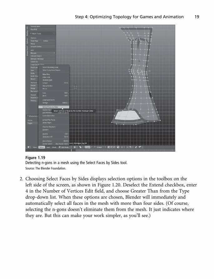
Figure 1.19Detecting n-gons in a mesh using the Select Faces by Sides tool.Source: The Blender Foundation.
2. Choosing Select Faces by Sides displays selection options in the toolbox on theleft side of the screen, as shown in Figure 1.20. Deselect the Extend checkbox, enter4 in the Number of Vertices Edit field, and choose Greater Than from the Typedrop-down list. When these options are chosen, Blender will immediately andautomatically select all faces in the mesh with more than four sides. (Of course,selecting the n-gons doesn’t eliminate them from the mesh. It just indicates wherethey are. But this can make your work simpler, as you’ll see.)
Step 4: Optimizing Topology for Games and Animation 19

Figure 1.20Selecting n-gons in a mesh. In this example, there’s one n-gon on the face.Source: The Blender Foundation.
3. One way to eliminate an n-gon is to use the Knife tool, rerouting mesh topology bycutting in new edge loops. You can access the Knife tool from the Tools panel whenyour mesh is in Edit mode. Simply click the Knife Tool button and move your cursorinto the viewport, clicking on a start and end vertex where a new cut (edge loop)should be inserted. Be sure to press the Enter key when you’re finished to confirmthe changes and insert the cut. The idea is to insert new detail into the model todissect the n-gon into either a triangle or a quad. See Figure 1.21 where the Knife toolsplits an n-gon into one quad and a triangle.
20 Chapter 1 n Preparation and Modeling

Figure 1.21Using the Knife tool to cut an n-gon into one quad and a triangle.Source: The Blender Foundation.
If your 2D characters were never going to be animated, then n-gons would perhaps beyour biggest enemy. But animation brings more threats and new guidelines. Specifically,whenever a mesh, like a leg or arm, bends, it affects the underlying mesh geometry,which also affects the nature of the bend. A mesh can only bend and deform whereverthere are vertices. For this reason, arms and legs especially should be regularly tessellated.That is, they should have equally spaced edges and vertices to support a smooth and pre-dictable deformation during animation, like a walk cycle. In addition, be sure to insertextra edge loops around hinged areas like joints such as the knee and hip. If you don’t,the mesh will look sharp and rigid at the area of the bend. See Figure 1.22 to see howI’ve configured edge loops around the knee area, inserting additional detail to support asmoother bend deformation.
Step 4: Optimizing Topology for Games and Animation 21
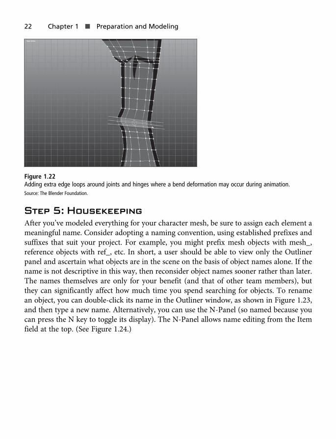
Figure 1.22Adding extra edge loops around joints and hinges where a bend deformation may occur during animation.Source: The Blender Foundation.
Step 5: HousekeepingAfter you’ve modeled everything for your character mesh, be sure to assign each element ameaningful name. Consider adopting a naming convention, using established prefixes andsuffixes that suit your project. For example, you might prefix mesh objects with mesh_,reference objects with ref_, etc. In short, a user should be able to view only the Outlinerpanel and ascertain what objects are in the scene on the basis of object names alone. If thename is not descriptive in this way, then reconsider object names sooner rather than later.The names themselves are only for your benefit (and that of other team members), butthey can significantly affect how much time you spend searching for objects. To renamean object, you can double-click its name in the Outliner window, as shown in Figure 1.23,and then type a new name. Alternatively, you can use the N-Panel (so named because youcan press the N key to toggle its display). The N-Panel allows name editing from the Itemfield at the top. (See Figure 1.24.)
22 Chapter 1 n Preparation and Modeling

Figure 1.23Assign meshes meaningful names to simplify object selection and project management.Source: The Blender Foundation.
Step 5: Housekeeping 23
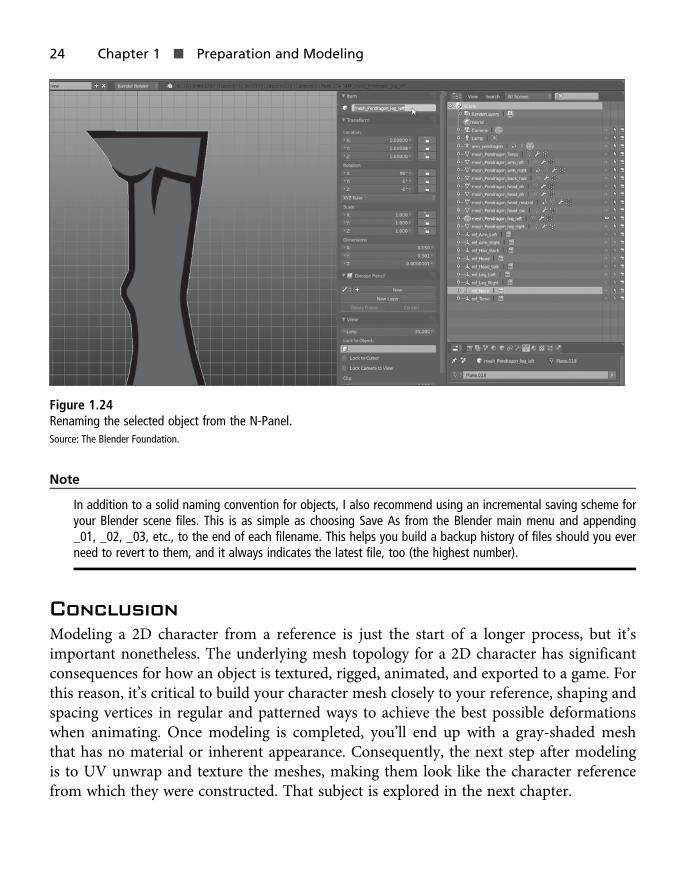
Figure 1.24Renaming the selected object from the N-Panel.Source: The Blender Foundation.
Note
In addition to a solid naming convention for objects, I also recommend using an incremental saving scheme foryour Blender scene files. This is as simple as choosing Save As from the Blender main menu and appending_01, _02, _03, etc., to the end of each filename. This helps you build a backup history of files should you everneed to revert to them, and it always indicates the latest file, too (the highest number).
ConclusionModeling a 2D character from a reference is just the start of a longer process, but it’simportant nonetheless. The underlying mesh topology for a 2D character has significantconsequences for how an object is textured, rigged, animated, and exported to a game. Forthis reason, it’s critical to build your character mesh closely to your reference, shaping andspacing vertices in regular and patterned ways to achieve the best possible deformationswhen animating. Once modeling is completed, you’ll end up with a gray-shaded meshthat has no material or inherent appearance. Consequently, the next step after modelingis to UV unwrap and texture the meshes, making them look like the character referencefrom which they were constructed. That subject is explored in the next chapter.
24 Chapter 1 n Preparation and Modeling
Chapter 2
UV Mapping and Texturing
The modeling stage, as defined in Chapter 1, “Preparation and Modeling,” is where thebasic form and shape of your character mesh is created. As you saw there, you use refer-ence images to construct separate meshes forming the limbs and moving parts of thecharacter, like arms and legs. These meshes will ultimately be imported into a gameengine like Unity, complete with texture and animation data.
By now, your completed Pendragon mesh should look like the one in Figure 2.1. Thischapter focuses on assigning texture information to the mesh using Blender. It’s aboutdrawing the character texture onto the mesh surface, effectively re-creating what is alreadyviewable in the reference images.
25

Figure 2.1The completed Pendragon mesh, ready for mapping and texturing.Source: The Blender Foundation.
Before starting the texturing stage, it helps to be confident that your mesh topology isexactly as you need it. Be sure your vertices, edges, and faces are positioned and sizedexactly where they should be in the mesh, free of n-gons. (For help removing n-gonsfrom a mesh, see the section “Step 4: Optimizing Topology for Games and Animation”in Chapter 1.) Why must you be so strict about mesh structure? Because UV-mappingdata is normally baked into the mesh vertices. That means changes in mesh vertices aftermapping can potentially distort and corrupt your mapping data, requiring you to tweakthe mapping or to remap from the beginning. Thankfully, as you’ll see, UV mapping a2D character is far quicker and more straightforward than mapping regular 3D objects.Making mapping changes, if they’re even necessary, is not such a big deal.
26 Chapter 2 n UV Mapping and Texturing

Note
The completed Pendragon model (without texturing information) is included in this eBook’s companion files inthe Chapter02 folder. You can open up this file and follow with this chapter if you prefer.
Step 6: Removing DoublesNo matter how carefully you model in Blender, doubled-up vertices (called doubles) caneasily introduce themselves into your mesh. A double is where two or more vertices arestacked one on top of the other so that, to the eye, it appears that only one vertex is pres-ent. These are typically introduced into your mesh through Extrude and Bevel operations,especially if you’ve attempted to undo them. These operations, though initiated with oneclick of a button, often involve multiple steps under the hood in Blender, and they requiremultiple undos to be fully undone. That’s why a single undo can sometimes leave youwith doubles.
Thankfully, Blender offers an easy tool for removing doubles: Remove Doubles. It’simportant to use this before mapping to make sure your mesh is structured exactly as itappears. To remove all doubles from a mesh, follow these steps:
1. Enter Edit mode by pressing the Tab key (Maya style controls).
2. Press Ctrl+A to select all vertices.
3. From the 3D View menu, select Mesh > Vertices > Remove Doubles. (See Figure 2.2.)This removes all doubles by merging them into one vertex. That is, it merges togetherall separate vertices occupying the same location.
Step 6: Removing Doubles 27

Figure 2.2Removing all doubles in a mesh in preparation for mapping.Source: The Blender Foundation.
Step 7: Creating the Character Atlas TextureBefore UV mapping a character mesh, you must first think about the texture you’ll bemapping. The reference images used so far for building the mesh contain all the texturedata you need, but the different limbs and elements were stored in separate texture files.This is both inconvenient and problematic. For texturing an object, it’s better to consoli-date all the different elements onto one texture, known as an atlas. (See Figure 2.3.) Thishas a couple of benefits. First, you can map all the character parts within the same texturespace, reusing and recycling the same texture. Second, atlas textures can offer enhancedrun-time performance for many different engines, include Unity and the Unreal Engine.
28 Chapter 2 n UV Mapping and Texturing

Figure 2.3Copying and pasting the character parts onto a single texture sheet (in other words, an atlas texture).Source: The Blender Foundation.
When creating an atlas texture, avoid positioning elements close to the image’s edges.Leave some space (known as pixel padding) between the elements and the image’s edges.This optimizes your texture for real-time game renderers. If you don’t do this, you mayobserve artifacts and glitches around the edges of your texture when applied to the meshin-game.
In addition, notice in Figure 2.3 how the outline pixels of character elements have beenexpanded. The exterior black borders are thicker and the blue color on the sleeve goesbeyond the shoulder joints. These expanded areas were created by standard paint toolsfound in most paint programs. Their purpose is to create some pixel duplication for eachelement. This is known as manual clamping. Its aim is to compensate for the way real-time render systems draw textures. They sometimes render border pixels or pixels justslightly outside where they should go. Including expanded pixels around your elementsin this way ensures that mismatching background pixels won’t be drawn instead.
Note
Common paint programs used for creating game textures include Adobe Photoshop (http://www.adobe.com/uk/products/photoshop.html), Paint Shop Pro (http://www.paintshoppro.com), and GIMP (http://www.gimp.org/).
Step 8: UV Preparation and ProjectionLet’s return to Blender to map the Pendragon mesh. UV mapping is a mathematical pro-cess in which a 3D object is structurally unraveled and flattened out onto a plane, allowinga two-dimensional texture to be mapped on it. The mapping information ultimately
Step 8: UV Preparation and Projection 29

defines how a texture should be projected onto a 3D surface, making it look like some-thing believable as opposed to a dull gray object. (Refer to Figure 2.1.) When mapping3D objects like cubes, cylinders, and spheres, you typically insert cuts or splices intothe model at locations where it should come apart to unfold. In Blender, these cutsare known as seams. 2D objects and characters like Pendragon, however, don’t need man-ually marked seams. That’s because, being flat and 2D, they are by nature alreadyunwrapped.
To start the UV-mapping process for Pendragon, follow these steps:
1. Switch to the UV Editing interface in Blender. To do so, click the Screen Layoutdrop-down list (found in the Info panel at the top of the interface) and choose UVEditing, as shown in Figure 2.4. This activates the UV Editing interface, shown on theleft side of Figure 2.5. (The viewport is on the right.)
Figure 2.4Getting ready for UV mapping.Source: The Blender Foundation.
30 Chapter 2 n UV Mapping and Texturing

Figure 2.5The UV Editor is useful for mapping objects.Source: The Blender Foundation.
2. In the Image Editor, choose Image > Open Image (see Figure 2.6) or press Ctrl+O.Then select your texture from the dialog box that appears. In this case, notice howlarge the texture is and how little space the Pendragon elements occupy. This isbecause I plan to add more characters and graphics to the same texture sheet. Ifyou’re texturing just one character, however, then you should size your textureaccording to your needs—no larger and no smaller. Smaller textures cannotaccommodate your needs, and larger textures will have wasted space.
Step 8: UV Preparation and Projection 31

Figure 2.6Loading the Pendragon atlas texture into the UV Editing interface.Source: The Blender Foundation.
3. Make sure Blender Render (rather than Cycles Render) is selected as your activerender system. To do so, open the Renderer drop-down list in the Info panel andchoose Blender Render, as shown in Figure 2.7.
32 Chapter 2 n UV Mapping and Texturing

Note
This step is not essential, but it is recommended. This setting is important for getting reliable and clear real-time previews of your mesh and its texture in the viewport. When the texture is applied to your mesh, theCycles renderer will typically shade the mesh black by default. In contrast, Blender Render will immediatelygive you a real-time preview of the mesh with the texture applied. No further settings or adjustments arerequired.
Figure 2.7Setting the active renderer to Blender Render for easiest real-time texture previews.Source: The Blender Foundation.
4. Let’s start mapping the Pendragon mesh. Each element should be mappedindividually: head, arms, legs, torso, etc. Although the order doesn’t really matter, Itypically start with the head. To begin, select the head mesh in the viewport and pressthe Tab key to enter Edit mode.
5. Press Ctrl+A to select all the faces in the mesh. You’re selecting all the faces herebecause all of them should map together onto the texture. When the faces areselected, you may see a wireframe UV layout in the UV Editor, depending on howyour mesh is configured. (Right now it doesn’t matter either way because you’ll begenerating new mapping for the object soon.)
Step 8: UV Preparation and Projection 33

6. With the faces selected, click the Browse Image button in the UV Editor and select theatlas texture from the list that appears. This assigns the atlas texture to the selectedfaces. Initially, no tangible or visible change may be apparent. (See Figure 2.8.)
Figure 2.8Assigning the atlas texture to the selected faces.Source: The Blender Foundation.
7. Apply a UV project to the Pendragon head mesh. This will unwrap, or auto-calculate, how the mesh should be unraveled into texture space. To achieve this, firstswitch your viewport to a front orthographic view to get a direct view of your mesh.Then select the head mesh, enter Edit mode, and select all faces. Finally, switch to theShading/UVs tab in the toolbox, click the Unwrap drop-down list, and chooseProject from View. (See Figure 2.9.) The result should look like Figure 2.10. As youcan see, projecting a layout from an orthographic view produces a UV layout in theImage Editor that matches exactly with the head mesh in the viewport.
Caution
Don’t project from a perspective view because you’ll end up with distortion. If you accidentally project from thewrong view, repeat the Unwrap > Project from View operation to generate a new layout, overwriting theprevious one.
34 Chapter 2 n UV Mapping and Texturing

Figure 2.9Generating a UV layout by projecting from an orthographic view.Source: The Blender Foundation.
Figure 2.10Project from View produces a UV layout that matches the mesh shape in the viewport.Source: The Blender Foundation.
Step 8: UV Preparation and Projection 35

8. The UV layout is looking good in the Image Editor, but it’s also useful to see theresults of that mapping applied to the mesh surface as a texture in the 3D viewport.Your view might already be textured, depending on how Blender is configured. If it’snot, you can enable texture previewing by switching the 3D Viewport Shading modeto Textured, as shown in Figure 2.11. Notice that the head’s texture matches thelayout in the Image Editor.
Figure 2.11Displaying texture mapping in the 3D viewport.Source: The Blender Foundation.
Note
If your mesh looks completely black in the viewport after you switch to the Textured view, try enablingShadeless display. To do this, press N to open the N-Panel and select the Shadeless checkbox in the Shadinggroup.
Step 9: Creating UV Islands and MappingWhen you project a UV layout from the mesh, a UV island is generated in the UV ImageEditor. An island represents a single body of connected vertices (UVs) in the ImageEditor. Thus, the complete UV layout for the Pendragon head is a single island, and itcontrols the mapping for the entire mesh.
36 Chapter 2 n UV Mapping and Texturing

It’s unlikely that the mapping will look exactly as you need it to after projection, eventhough the layout does reflect the mesh proportions and shape. The island will typicallybe too large or too small and positioned incorrectly within the texture, as shown in Fig-ure 2.12. Before editing the mesh UV layout to correct these issues, first enter Islandmode. This restricts your selection to complete islands as opposed to individual vertices(called UVs in the Image Editor). Simply right-click inside the Image Editor and chooseIsland from the context menu that appears. Alternatively, click the Island Selection but-ton in the bottom toolbar of the Image Editor. (See Figure 2.13.)
Figure 2.12Editing mapping using UV islands.Source: The Blender Foundation.
Step 9: Creating UV Islands and Mapping 37

Figure 2.13Island Selection mode enables you to select and manipulate complete UV islands as opposed to single vertices(UVs).Source: The Blender Foundation.
You can reposition and resize islands through scaling and translation. The UV ImageEditor supports the transformation of islands, just as the 3D view supports the transfor-mation of meshes. Simply click a UV island and press W for movement or R for Scaling(Maya). You can also access the Transform tools for islands (Translate, Rotate, and Scale)from the UV Image Editor by choosing UVs > Transform. (See Figure 2.14.)
38 Chapter 2 n UV Mapping and Texturing
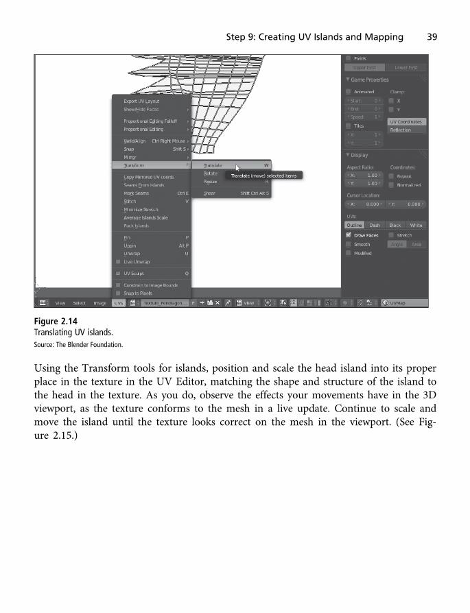
Figure 2.14Translating UV islands.Source: The Blender Foundation.
Using the Transform tools for islands, position and scale the head island into its properplace in the texture in the UV Editor, matching the shape and structure of the island tothe head in the texture. As you do, observe the effects your movements have in the 3Dviewport, as the texture conforms to the mesh in a live update. Continue to scale andmove the island until the texture looks correct on the mesh in the viewport. (See Fig-ure 2.15.)
Step 9: Creating UV Islands and Mapping 39

Figure 2.15Transforming the Head UV island into position.Source: The Blender Foundation.
Remember to slightly scale down the head UV island, leaving some extra padding aroundthe outside where there’s a black border. This is because in step 7, you created an atlas tex-ture where each part of the body was expanded with extra edge pixels, like a bolder blackborder. This is a safety margin of pixels to compensate for renderer inaccuracies duringgameplay and should not be intentionally mapped onto the mesh. (See Figure 2.16.)
Figure 2.16Leave some texture padding outside the UV island.Source: The Blender Foundation.
40 Chapter 2 n UV Mapping and Texturing

Sometimes simply translating and scaling an island, as you’ve done here, won’t be enoughto get it looking right on your mesh. In these cases, you’ll need to manually tweak specificUVs and to individually match the island with the texture more accurately. To achievethis, right-click in the UV Image Editor and select Vertex (see Figure 2.17). Alternatively,choose Vertex Mode from the UV Image Editor menu.
Figure 2.17Vertex mode enables you to tweak specific UVs in an island, just like tweaking vertices in a mesh.Source: The Blender Foundation.
With Vertex mode active in the UV Image Editor, you can select and transform UVs likeregular vertices. This lets you select erroneous vertices and move them into place to bringthe island into line with the texture. (See Figure 2.18.)
Step 9: Creating UV Islands and Mapping 41

Note
Unfortunately, Blender doesn’t currently support a transform gizmo (axes) for the UV Image Editor. I’d reallylike to see this feature. Right now, you must enter Translate mode and use the mouse to move the vertices totheir new location. No gizmo or visual indicator appears in the interface when translation occurs.
Figure 2.18Translate UVs into place to tweak and refine a UV island.Source: The Blender Foundation.
42 Chapter 2 n UV Mapping and Texturing
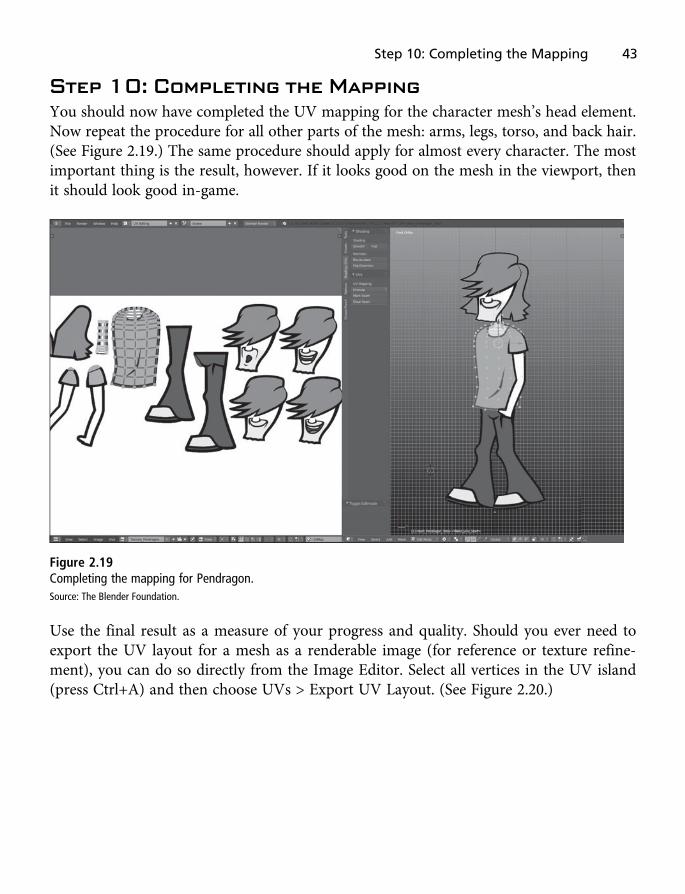
Step 10: Completing the MappingYou should now have completed the UV mapping for the character mesh’s head element.Now repeat the procedure for all other parts of the mesh: arms, legs, torso, and back hair.(See Figure 2.19.) The same procedure should apply for almost every character. The mostimportant thing is the result, however. If it looks good on the mesh in the viewport, thenit should look good in-game.
Figure 2.19Completing the mapping for Pendragon.Source: The Blender Foundation.
Use the final result as a measure of your progress and quality. Should you ever need toexport the UV layout for a mesh as a renderable image (for reference or texture refine-ment), you can do so directly from the Image Editor. Select all vertices in the UV island(press Ctrl+A) and then choose UVs > Export UV Layout. (See Figure 2.20.)
Step 10: Completing the Mapping 43
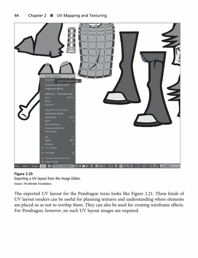
Figure 2.20Exporting a UV layout from the Image Editor.Source: The Blender Foundation.
The exported UV layout for the Pendragon torso looks like Figure 2.21. These kinds ofUV layout renders can be useful for planning textures and understanding where elementsare placed so as not to overlap them. They can also be used for creating wireframe effects.For Pendragon, however, no such UV layout images are required.
44 Chapter 2 n UV Mapping and Texturing

Figure 2.21The exported UV layout for the Pendragon torso.Source: The Blender Foundation.
ConclusionYou should now have a completely modeled and textured Pendragon character that looksjust like the character reference image. It’s an important step, and represents an end pointof sorts. Specifically, the character is now modeled and textured, and is created in full as agame-ready entity. What remains is the animation part—where you configure the char-acter to walk in a complete, looping cycle. Even at this early stage, you could importthe character into a game engine, but he would be imported as a static and motionlessentity—looking more like a cardboard cutout than an animated and living thing. Nowit’s time to breathe that kind of life into the model. In the next chapter, you’ll explorerigging, a preparatory stage to animation.
Conclusion 45

This page intentionally left blank

Chapter 3
Rigging, Bones, and Weights
When you’ve fully modeled and textured your character, as you have Pendragon, it’s easyto feel excited about animation. It’s considered a “best practice” to think about animationearly in this way, getting as clear and precise an idea of the range of animations needed.Indeed, you shouldn’t approach animation without such ideas! But even beyond these, it’simportant to prepare technically and logistically for animation, making sure your mesh isthe kind of object that Blender can animate well, with all the power you need. This kind ofsoftware-specific preparation is known as rigging.
With rigging, you generate a skeleton or bone structure underpinning the mesh, ensuringevery joint or bend point has a corresponding set of bones in the skeleton. A link is thengenerated between the skeleton and the mesh so that when the skeleton moves, the meshwill move along with it, conforming and bending. (See Figure 3.1.) The linkage betweena skeleton and a mesh is known as skinning information or weighting. Creating askeleton object that is separate from the mesh is useful because in theory, the skeletoncan be reused on other bipedal meshes. This enables you to run a single animation onmultiple objects.
47

Figure 3.1Rigging defines the underlying mechanical structure of a mesh.Source: The Blender Foundation.
In this chapter, you’ll explore the complete process of rigging Pendragon using bones andweights, resulting in a character that deforms well during animation. You will use Blen-der’s animation tools to create the actual walking animation in Chapter 4, “Animation.”
Note
The completed Pendragon model, ready for rigging, is included in the eBook companion files in the Chapter03folder. You can open this file and follow with this chapter if you prefer.
Step 11: Creating ArmaturesThe Blender term for a skeleton is armature. An armature is a special control object thatdefines the mechanical structure of a model—the position of its limbs and joints. Itdoesn’t matter if you’re modeling a human, a monster, a mechanical digger, or a lengthof rope—an armature specifies the underlying pieces of the model in a general andabstract way. This makes armatures very important for animation.
48 Chapter 3 n Rigging, Bones, and Weights

The Pendragon character needs an armature to define how its legs, arms, and head areconnected to the torso, and how the whole bone system works together when in motion.To create the armature, follow these steps:
1. Center your mesh. If your character mesh is not centered at the scene origin, thennow is an ideal time to make it so. It’ll make working with and exporting armaturesmuch easier. The character’s pivot, or center, is usually at the base of the feet—in thehorizontal center, where they make contact with the ground. I recommend movingyour meshes such that the foot is positioned at the origin. Then reset, or clear, theobject transformation data by first selecting Object > Apply > Location and thenselecting Object > Apply > Rotation & Scale. (See Figure 3.2.)
Figure 3.2Positioning the character mesh with its feet at the world origin.Source: The Blender Foundation.
Step 11: Creating Armatures 49

2. Position the different parts together using scene depth to offset some of them, likethe arms and legs, either closer to or farther from the camera. That is, move someparts deeper into the scene than others. Each limb must be drawn at the rightdepth setting when viewed in the front orthographic viewport. For example, the leftarm must appear in front of the torso and the right arm behind. Don’t movebones too far apart, though, as this will affect how Blender skins the mesh later!(See Figure 3.3.)
Figure 3.3Offsetting character parts to simulate depth.Source: The Blender Foundation.
3. To create an armature that’s easy to tweak, disable object selection. That is, select thePendragon pieces in the scene (arm, head, torso, etc.) and use the Outliner windowto disable the Selection icon for each piece. That way, you won’t be able to selectthem by accident. This will make it easier to see the Pendragon as a reference,without selecting it in the viewport. (See Figure 3.4.)
50 Chapter 3 n Rigging, Bones, and Weights

Figure 3.4Disabling mesh selection in preparation for rigging.Source: The Blender Foundation.
4. Switch to a front orthographic view and activate the Create panel in the toolbox.
5. Click the Armature button to create a new armature object in the scene at the positionof the 3D cursor. (This should be the world origin.) This creates an aligned armaturewith a single, large bone, as shown in Figure 3.5. Note that the bone may initiallyappear larger than the mesh. That’s not a problem, however. You’ll correct it shortly.
Step 11: Creating Armatures 51

Figure 3.5Creating a new armature in the scene. Armatures begin with a single, large bone.Source: The Blender Foundation.
6. Depending on the position of your mesh and armature, your mesh may appear infront of or intersecting the armature. But when creating and posing armatures, it’simportant to see the bones clearly, so you’ll usually want them to appear in front ofthe mesh (even if your mesh is actually closer to the viewport camera). To achievethis, use X-Ray mode. Simply switch to the Object Data tab in the Properties paneland select the X-Ray checkbox in the Display group. (See Figure 3.6.) This forcesBlender to render the armature in front of all meshes.
52 Chapter 3 n Rigging, Bones, and Weights

Figure 3.6Viewing armatures in front of other objects, including meshes.Source: The Blender Foundation.
Step 12: Creating BonesIn Blender, armatures can be in one of three modes:
n Object mode: The default, Object mode lets you to select and transform a completearmature.
n Edit mode: This mode lets you dig deeper into an armature, creating a connectedbone layout.
n Pose mode: Pose mode lets you animate the armature bones.
Step 12: Creating Bones 53

After creating an armature, the next phase is to create a bone layout that maps onto yourcharacter mesh. Follow these steps:
1. Enter Edit mode by pressing the Tab key or by choosing Edit Mode from the Modedrop-down list on the toolbar, as shown in Figure 3.7.
Figure 3.7In Edit mode, an armature bone layout is defined.Source: The Blender Foundation.
2. Having created an armature object, the first bone in the skeleton will be createdautomatically for you. This will be the hip bone, which will serve as the parent for thewhole hierarchy of bones. Select the main part of the bone, not the spherical sectionson the end (the head and tail), and use the Transform and Scale tools to position andscale the bone into place at the character’s hip. (Note that selection, translation, andscaling work the same way for bones as they do for meshes.) If you need to changethe angle and orientation of the bone, you can transform the head and tail sections.See Figure 3.8.
54 Chapter 3 n Rigging, Bones, and Weights

Figure 3.8Creating the character’s hip bone.Source: The Blender Foundation.
3. It’s important to give each bone a unique and meaningful name, to clearlydistinguish one bone from another. This will be especially important later, when youskin and animate the mesh, because you will need to select and reference each boneby name. To name a bone, select it in Edit mode and rename it, just as you’d renameany other object. I’ve named the first bone “Hip.” (See Figure 3.9.)
Step 12: Creating Bones 55

Figure 3.9Give each bone a meaningful name.Source: The Blender Foundation.
4. Use the Extrude tool to create a new bone connected to the existing one. To do so,select the head of the hip bone and choose Armature > Extrude from the viewportmenu (see Figure 3.10) or press Alt+X. Use the transform axes to constrain theextrusion upward into the torso. This newly created bone represents Pendragon’slower torso.
56 Chapter 3 n Rigging, Bones, and Weights

Figure 3.10Extrude a new bone using the Extrude tool.Source: The Blender Foundation.
5. Name the bone that represents Pendragon’s lower torso Torso.Lower.
6. You want to split the torso into two main, vertically aligned bones, allowing at leastone bend, as shown in Figure 3.11. This lets you create animations in whichPendragon crouches over, dances, or sways. Extrude a new bone from the lower torsofor the upper torso and name it Torso.Upper. If required, transform the bone headsand tails to adjust the angle and incline, conforming to the mesh. Remember to keepall bones in the same plane (at the same depth in the scene), however. The characteris a flat, 2D mesh, after all!
Step 12: Creating Bones 57

Figure 3.11Creating bones for the torso: lower and upper.Source: The Blender Foundation.
7. Select the head of the upper torso bone, where it comes close to the character’s neck.Then extrude a bone outward to the right to meet the top of the character’s left arm,positioning it where the upper arm socket would be.
8. Select the head of the upper torso bone a second time and extrude another bone, butin the opposite direction. This bone should match up with the right arm, whichappears behind the character’s torso. Remember to name each bone appropriately—for example, Shoulder.l and Shoulder.r. (See Figure 3.12.)
58 Chapter 3 n Rigging, Bones, and Weights

Figure 3.12Creating shoulder bones.Source: The Blender Foundation.
9. Complete the upper body, head, and arms, as shown in Figure 3.13. As you can see,the torso has two bones, there are two shoulder bones, and there is one neck bone.The head consists of one bone, while each arm consists of two bones (upper andlower arm). In addition, I’ve created one additional bone for each hand. Pendragonwill not move individual fingers, so you don’t need to rig those. (For more realistic,non-cartoon characters, you may need to rig the hand using multiple bones,depending on your needs.) Notice that the bone joints—the heads and tails—correspond to the real joints in the model, such as the elbows and shoulder joints.This is important for producing clean and reliable deformations during animation.
Step 12: Creating Bones 59

Figure 3.13Completing the upper body.Source: The Blender Foundation.
10. Next, you’ll complete the character’s legs and feet. Note, however, that these requirespecial consideration. Thus far, all the bones you’ve created are directly connected toanother bone. A bone tail touches the head of a neighboring bone, and so on in abone chain until it reaches an end point, such as the head or hands. The legs,however, work slightly differently: They won’t be directly connected to the mainbody. Rather, they’ll be offset. This is because the legs will work as a separate,self-contained system from the rest of the body. Doing this is not essential, but itmakes animating the legs simpler, enabling you to edit them in isolation withoutaffecting the rest of the body. Start by creating the leg left. To create this bone, clickthe Add button in the Bones group in the Armature Tools panel, which is accessibleonly when the armature is in Edit mode. (See Figure 3.14.) This creates a new,disconnected bone in the armature.
60 Chapter 3 n Rigging, Bones, and Weights

Figure 3.14Adding a new and disconnected bone to the armature in preparation for rigging the legs.Source: The Blender Foundation.
11. Position the bone head and tail along the upper leg, or the thigh (thigh.l and thigh.r).The bone tail should be where the upper leg connects to the hip and the bone headshould be at the knee joint. (See Figure 3.15.)
Step 12: Creating Bones 61

Figure 3.15Creating the thigh bone.Source: The Blender Foundation.
12. Connect the thigh bone to the hip, making it a child bone. To do this, click the thighbone to select it, and then Shift-click the hip bone, selecting both bones. Then pressCtrl+P or choose Armature > Parent > Make from the viewport menu, as shown inFigure 3.16. A context menu appears; choose Keep Offset. This parents the thigh tothe hip while maintaining the bone’s position. This parent-child relationship betweenthe hip and thigh is useful; whenever the hip moves, the leg will follow along.
62 Chapter 3 n Rigging, Bones, and Weights

Figure 3.16Connecting the thigh to the hip bone.Source: The Blender Foundation.
13. Repeat steps 10–12 to create the right thigh.
14. From each thigh bone, extrude downward to create a lower leg bone that reaches tothe ankle area (shin.l and shin.r).
15. Pendragon will have only one bone for each foot. To create this bone, extrude it outfrom the shin bone on each leg.
Step 12: Creating Bones 63
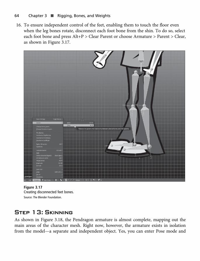
16. To ensure independent control of the feet, enabling them to touch the floor evenwhen the leg bones rotate, disconnect each foot bone from the shin. To do so, selecteach foot bone and press Alt+P > Clear Parent or choose Armature > Parent > Clear,as shown in Figure 3.17.
Figure 3.17Creating disconnected feet bones.Source: The Blender Foundation.
Step 13: SkinningAs shown in Figure 3.18, the Pendragon armature is almost complete, mapping out themain areas of the character mesh. Right now, however, the armature exists in isolationfrom the model—a separate and independent object. Yes, you can enter Pose mode and
64 Chapter 3 n Rigging, Bones, and Weights

move the bones around using the Translate and Rotate tools, but the Pendragon modelitself won’t conform to the bone transformations. For example, moving the leg boneswon’t move the leg areas of the Pendragon mesh. Now it’s time to establish thatconnection—a process called skinning.
Figure 3.18Completing the Pendragon skeleton.Source: The Blender Foundation.
1. Combine all the Pendragon mesh elements into one object. To do so, select all themesh parts—the head, arms, legs, etc.—and click the Join button (available from thetoolbox when the mesh is in Object mode). Don’t worry, you can separate the partsagain later, if required. See Figure 3.19.
Step 13: Skinning 65

Figure 3.19Joining the Pendragon parts together in preparation for skinning.Source: The Blender Foundation.
2. Position the Pendragon mesh in the 3D viewport so it overlaps and intersects withthe bones created in the armature (if they don’t already). That is, the leg bonesshould intersect the leg region of the Pendragon mesh, and so on. This will beimportant later, when Blender calculates how the bones in the armature should affect
66 Chapter 3 n Rigging, Bones, and Weights

the character mesh. Note that the positioning doesn’t have to be exact. A general,by-eye judgment is usually good enough. (See Figure 3.20.)
Figure 3.20Intersecting bones with the Pendragon mesh.Source: The Blender Foundation.
3. In the Outliner, drag and drop the Pendragon mesh object on top of the armature toparent it to the armature. This makes the mesh a child of the armature. When youparent the mesh to the armature, Blender establishes a connection between the twoobjects.
4. A context menu appears. Choose Armature Deform with Automatic Weights, asshown in Figure 3.21. Blender automatically generates skinning information for themesh based on its best guess as to how you expect the bones in the armature to relateto the intersecting mesh. To test the effect, move the armature bones in Pose mode.The Pendragon mesh will deform in response.
Step 13: Skinning 67

Figure 3.21Generating automatic weights for the Pendragon character.Source: The Blender Foundation.
The aim of skinning is, ultimately, to get the balance of weighting correct across allvertices in the mesh so that each vertex is affected exactly as intended by each bone inthe armature. Typically, the automatic weighting will be correct, but there may be timeswhen it generates errors that must be corrected. To correct these errors, you must firstunderstand how Blender encodes the skinning information. Blender encodes this informa-tion into vertex groups, which are baked into the mesh object itself. Each bone in an arma-ture has one vertex group, which is named after the bone. A bone’s vertex group containsthe complete set of vertices in the mesh to be affected by that bone. Each vertex in the sethas a weight value between 0 and 1, which determines how strongly that vertex will beaffected by the bone. A value of 0 indicates there will be no effect, a value of 1 indicatesa full effect, a value of 0.5 indicates something in the middle, and so on. To view all thevertex groups for a mesh, see the Vertex Groups section of the Object Data tab in theProperties panel, shown in Figure 3.22.
68 Chapter 3 n Rigging, Bones, and Weights

Figure 3.22Viewing skinning information for a mesh.Source: The Blender Foundation.
To display the weighting for any specific vertices as they relate to bones in the armature,select them in the mesh. To select whole groups of vertices for each limb in the mesh(such as all vertices in the arm, leg, or head), select one vertex in the limb and then pressCtrl+L or choose Select > Linked from the viewport menu (see Figure 3.23). This selectsall connected vertices in the chosen limb. You can then inspect the weighting for the ver-tices from the Vertex Groups section of the Object Data tab. If you need to adjust theweighting, enter a new value for the Weight field and click the Assign button. This assignsthe value to the selected vertex group. For example, if you were to assign a value of 0 to
Step 13: Skinning 69

the selected vertices in the Left_Arm group, then those vertices would no longer beaffected by the left arm bone in the armature.
Figure 3.23Inspecting weight data for the arm.Source: The Blender Foundation.
Although Blender’s automatic weighting is usually very accurate and requires only a fewtweaks, 2D meshes like the Pendragon mesh probably require more tweaking. Before pro-ceeding, however, I prefer to decouple the mesh from the armature, returning it to anindependent object. Then I use a modifier to connect the armature to the mesh ratherthan using a parent-child relationship. That way, I can easily switch the armature-meshconnection on and off from the Properties panel. (I only use the drag-and-drop parentingmethod to generate the initial automatic weight data.) Follow these steps:
1. In the Outliner, drag and drop the mesh back to its original location. Alternatively,select Object > Parent > Clear Parent from the viewport menu. This removes theconnection between the armature and the mesh, but the vertex group data andskinning information remain intact.
70 Chapter 3 n Rigging, Bones, and Weights

2. Select the Pendragon mesh in the viewport, open the Modifiers tab, click theAdd Modifier drop-down list, and choose Armature from the Deform group.(See Figure 3.24.) Then select the armature in the scene using the Object field inthe Properties panel. This re-establishes the link between the mesh and armature.
Figure 3.24Connecting the mesh to an armature with the Armature modifier.Source: The Blender Foundation.
Step 14: Adjusting the WeightingThe automatic weighting applied to the Pendragon mesh will be inaccurate becauseBlender doesn’t grasp that the model should be 2D. To see the extent of the inaccuracy,pose the armature in Pose mode and ascertain just how badly the bones deform the char-acter mesh. As shown in Figure 3.25, bones in the arm affect areas of the torso, and bones
Step 14: Adjusting the Weighting 71
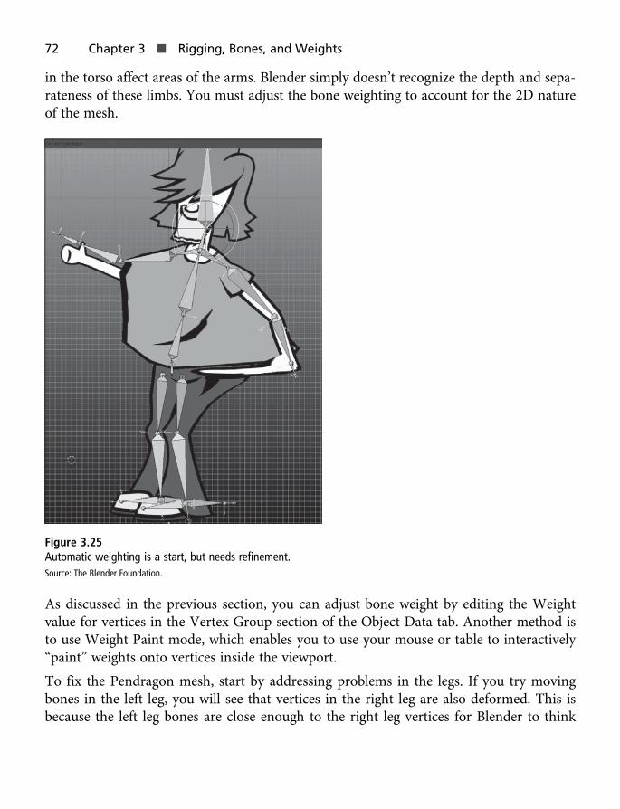
in the torso affect areas of the arms. Blender simply doesn’t recognize the depth and sepa-rateness of these limbs. You must adjust the bone weighting to account for the 2D natureof the mesh.
Figure 3.25Automatic weighting is a start, but needs refinement.Source: The Blender Foundation.
As discussed in the previous section, you can adjust bone weight by editing the Weightvalue for vertices in the Vertex Group section of the Object Data tab. Another method isto use Weight Paint mode, which enables you to use your mouse or table to interactively“paint” weights onto vertices inside the viewport.
To fix the Pendragon mesh, start by addressing problems in the legs. If you try movingbones in the left leg, you will see that vertices in the right leg are also deformed. This isbecause the left leg bones are close enough to the right leg vertices for Blender to think
72 Chapter 3 n Rigging, Bones, and Weights
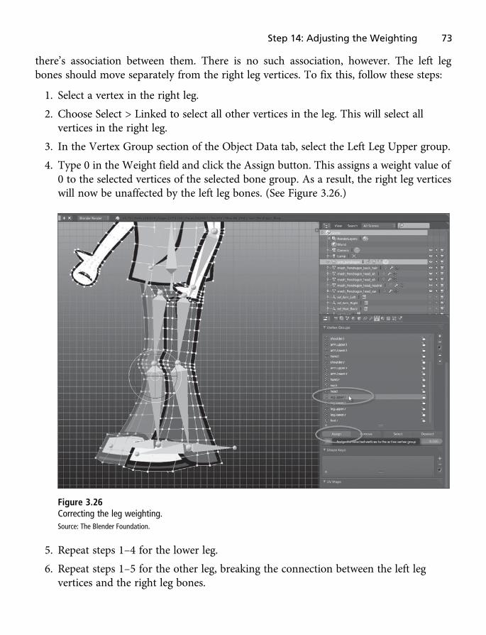
there’s association between them. There is no such association, however. The left legbones should move separately from the right leg vertices. To fix this, follow these steps:
1. Select a vertex in the right leg.
2. Choose Select > Linked to select all other vertices in the leg. This will select allvertices in the right leg.
3. In the Vertex Group section of the Object Data tab, select the Left Leg Upper group.
4. Type 0 in the Weight field and click the Assign button. This assigns a weight value of0 to the selected vertices of the selected bone group. As a result, the right leg verticeswill now be unaffected by the left leg bones. (See Figure 3.26.)
Figure 3.26Correcting the leg weighting.Source: The Blender Foundation.
5. Repeat steps 1–4 for the lower leg.
6. Repeat steps 1–5 for the other leg, breaking the connection between the left legvertices and the right leg bones.
Step 14: Adjusting the Weighting 73
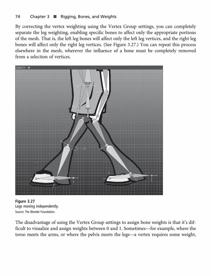
By correcting the vertex weighting using the Vertex Group settings, you can completelyseparate the leg weighting, enabling specific bones to affect only the appropriate portionsof the mesh. That is, the left leg bones will affect only the left leg vertices, and the right legbones will affect only the right leg vertices. (See Figure 3.27.) You can repeat this processelsewhere in the mesh, wherever the influence of a bone must be completely removedfrom a selection of vertices.
Figure 3.27Legs moving independently.Source: The Blender Foundation.
The disadvantage of using the Vertex Group settings to assign bone weights is that it’s dif-ficult to visualize and assign weights between 0 and 1. Sometimes—for example, where thetorso meets the arms, or where the pelvis meets the legs—a vertex requires some weight,
74 Chapter 3 n Rigging, Bones, and Weights

but its influence should be moderated. In these cases, it’s easier to use Weight Paint modeto define bone strength. To experiment with this mode, follow these steps:
1. In Pose mode, select the armature’s upper arm bone. (I’ll start with the left arm,though other bones may also need tweaking in this way.) You’ll now control itsweighting with the torso region. (See Figure 3.28.)
Figure 3.28Select a bone in the armature.Source: The Blender Foundation.
2. Select the part of the mesh whose weights must be edited for the selected bone—inthis case, the torso area.
3. In Edit mode, select all the faces in the torso. To do so, pick one vertex in the torsoand press Ctrl+L or choose Select > Linked from the viewport menu. Then switch toFace mode to select all the torso faces. (See Figure 3.29.)
Step 14: Adjusting the Weighting 75

Figure 3.29Select all faces whose weighting must be edited.Source: The Blender Foundation.
4. Open the Mode drop-down list at the bottom of the viewport and choose WeightPaint. In Weight Paint mode, the shading of the mesh in the viewport changes to acolor scheme of blue, green, orange, and red. Mesh areas marked in blue arecompletely uninfluenced by the selected bone in the armature (Weight: 0). Incontrast, mesh areas marked in red are fully affected by the selected bone (Weight: 1).(You can think of the blue areas as being “cold,” the red areas as being “hot,” andthe green and orange areas as being somewhere in between.)
5. When Weight Paint mode is active, brush tools become available in the toolbox onthe left. (See Figure 3.30.) These enable you to “paint” using the mouse or a tablet.The Radius setting defines the size of the brush, and the Weight value determines theweight to be painted onto the vertices when that brush is applied. To paint, simplyclick the desired area in the mesh.
76 Chapter 3 n Rigging, Bones, and Weights

Figure 3.30Weight Paint mode.Source: The Blender Foundation.
6. By default, painting affects all vertices in the mesh, not just the selected ones. Thiscan be frustrating if you want to restrict the effect to specific faces, such as those inthe torso or arm. Fortunately, you can use Blender’s Face Selection masking featureto limit weight painting to the selected faces. To toggle this option on, click the Face
Step 14: Adjusting the Weighting 77
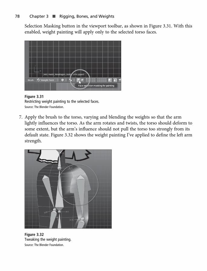
Selection Masking button in the viewport toolbar, as shown in Figure 3.31. With thisenabled, weight painting will apply only to the selected torso faces.
Figure 3.31Restricting weight painting to the selected faces.Source: The Blender Foundation.
7. Apply the brush to the torso, varying and blending the weights so that the armlightly influences the torso. As the arm rotates and twists, the torso should deform tosome extent, but the arm’s influence should not pull the torso too strongly from itsdefault state. Figure 3.32 shows the weight painting I’ve applied to define the left armstrength.
Figure 3.32Tweaking the weight painting.Source: The Blender Foundation.
78 Chapter 3 n Rigging, Bones, and Weights

8. Continue weight painting and manually setting the weights of vertex groups until allbones in the armature affect the Pendragon mesh as required. Each limb shouldmove believably with the rest of the body, without pulling and deforming unintendedregions. This process can be long and laborious, especially for more intricate mesheswith props, costumes, and unconventional anatomy. But it’s necessary and worth it!
Step 15: Applying Inverse KinematicsThe final rigging issue to consider is Inverse Kinematics (IK). In the case of Pendragon, IKrelates specifically to the legs, but it can also apply to arms or any other long chain ofbones.
As things stand right now, to animate the character’s legs for a walking motion, you’dhave to start by rotating the thigh bone, then the shin bone, and then the foot bone, work-ing from the top to the bottom of the bone chain until the foot lands exactly where youneed it to for every frame in the animation. Although this approach would work, and overtime could create an entirely believable animation, it’s tedious to transform so many dif-ferent bones. It’d be better if you could simply grab the feet bones, position them whereveryou need to, and then have the armature automatically calculate how the intervening shinand thigh bones should rotate and bend (while respecting the hip and feet bone positions).This, in essence, is what IK allows you to do. In this section, you’ll use IK to complete therig for the feet.
1. Select each foot bone, then press Alt+X to extrude one bone out from the back ofeach foot bone. Then press Alt+P to disconnect this new bone from the foot, leavingit in place as an isolated bone. (See Figure 3.33.) These bones will be used internallyby Blender’s IK system to mark the end points of a bone chain representing the leg.Name the bones leg.ik.l and leg.ik.r.
Step 15: Applying Inverse Kinematics 79

Figure 3.33Creating IK handle bones marking the end of a bone chain.Source: The Blender Foundation.
2. In Pose mode, select the shin bone for each leg (the lowest bone in the leg chain).Then, in the Bone Constraints tab in the Properties panel, open the Add BoneConstraint drop-down list and choose Inverse Kinematics, as shown in Figure 3.34.
Figure 3.34Adding an Inverse Kinematics constraint to the shin bone.Source: The Blender Foundation.
80 Chapter 3 n Rigging, Bones, and Weights

3. In the Inverse Kinematics settings, open the Target list and select the armature, openthe Bone list and select the appropriate IK bone for each leg (either leg.ik.l orleg.ik.r), and specify a Chain Length of 2, as shown in Figure 3.35. (This is becausethere are a total of two bones in the bone chain: the shin bone and the thigh bone.)
Figure 3.35Configuring the IK constraint.Source: The Blender Foundation.
Note
In Figure 3.35, the IK target is listed as “arm_pendragon.” Remember, the prefix “arm” is an abbreviation for“armature” (skeleton), and does not refer to one of the character’s arms.
4. It’s a good practice to impose specified limits on bone rotation for IK. For example, ifa leg bends at the knee, there are two ways it can rotate: inward and outward. Butonly the outward rotation is acceptable, since legs cannot bend in both directions. Toprevent Blender from getting confused, you can apply rotation constraints to the shinbone. To do so, select the shin bone, switch to the Bone Data tab in the Propertiespanel, and scroll down to the Inverse Kinematics group. There, lock rotation entirelyon the X and Y axes and limit rotation on the Z axis between 0 and 180 degrees. Asyou do this, a rotation arc appears in the viewport, offering a preview of theacceptable limits for rotation. (See Figure 3.36.)
Step 15: Applying Inverse Kinematics 81
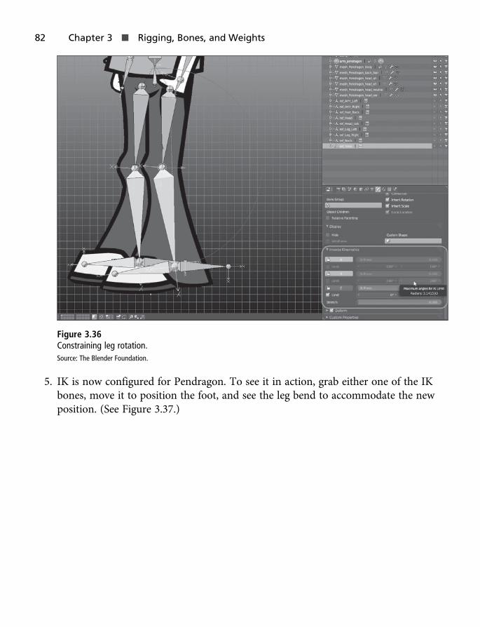
Figure 3.36Constraining leg rotation.Source: The Blender Foundation.
5. IK is now configured for Pendragon. To see it in action, grab either one of the IKbones, move it to position the foot, and see the leg bend to accommodate the newposition. (See Figure 3.37.)
82 Chapter 3 n Rigging, Bones, and Weights

Figure 3.37Positioning the feet with IK.Source: The Blender Foundation.
6. IK even works if you position the hip/pelvis bone instead of the feet, keeping the feeton the floor. This time, the character bends automatically at the knees, as thoughcrouching. (See Figure 3.38.)
Step 15: Applying Inverse Kinematics 83

Figure 3.38Moving the hips with IK.Source: The Blender Foundation.
ConclusionSplendid! The Pendragon character is now modeled, textured, and fully rigged for anima-tion. You accomplished the rigging using a combination of armatures, skinning, andInverse Kinematics. The general process is not short or obvious, but it’s rewarding becausethe feature set gives you enormously flexible and far-reaching control over the pose for acharacter. With a rig in place designed to accommodate your animation needs, it’s nowtime to move on to the process of animation itself. In that phase, you’ll animate the poseof the armature over time and let it work its magic on your mesh to create a believablewalk sequence that you can reuse for a real-time video game.
84 Chapter 3 n Rigging, Bones, and Weights

Chapter 4
Animation
In this chapter, you’ll take your fully modeled, textured, and rigged character and animatehim through a complete walk cycle using the Blender animation tools. (See Figure 4.1.)
Figure 4.1The rigged and animated Pendragon character.Source: The Blender Foundation.
85

The term walk cycle means two things for animation and video games specifically:
n Your character will walk in a loopable and seamless way. That means you’ll be ableto play back the animation on a loop to make him walk continuously for as long asyou need.
n The character will walk in-place. That means he’ll walk on the spot, moving his legs,arms, and head and exhibiting all walking motions, but without actually movingforward in space. That’s very important for games. It lets you move a pre-animatedand walking character wherever you need during gameplay. This kind of walk cyclewill play in-game without overriding or disrupting the general character motion,which often changes and is controlled by the player in real time.
To achieve these two features for walking, you’ll use all three Blender animation toolsets:the Timeline, the Dope Sheet, and the Graph Editor. Let’s get started!
Note
The completed Pendragon model, including rigging information, is included in the eBook companion files in theChapter04 folder. You can open the file and follow with this chapter, if you prefer.
Step 16: Preparing for AnimationBefore animating the Pendragon character, let’s tweak and configure Blender to enhanceyour workflow. Follow these steps:
1. Change the default interface configuration to the Animation preset, which displaysall three animation windows alongside the 3D viewport and Properties panel.This makes it easier to edit the animation and preview the results in real time.(See Figure 4.2.)
86 Chapter 4 n Animation

Figure 4.2Enabling the Animation layout for Blender.Source: The Blender Foundation.
2. The total frame duration for the walk animation should be 32 frames, so set theframe range in the Timeline window. To achieve this, type 1 in the Start setting andtype 33 in the End setting. (Note that the final frame is 33 and not 32 because it willeffectively be a duplicate of the first frame to create a looping sequence.)
3. To make things clearer, I like to add markers (text handles) in the Timeline windowto show human-readable messages about where the start and end of animation is.To set a marker for frame 1, right-click the first frame in the Timeline window to setthe playhead at that frame. Then press the M key to insert the marker or choose
Step 16: Preparing for Animation 87

Marker > Add Marker from Timeline menu. (See Figure 4.3.) To rename the marker,click it to select it and press Ctrl+M or Choose Marker > Rename Marker from theTimeline menu.
Figure 4.3Creating a frame range and markers.Source: The Blender Foundation.
Note
To position or slide the animation playhead in the Timeline or Dope Sheet, just right-click using the MayaControls. For the Graph Editor, however, you must hold down the K key while left-clicking. You can changethe controls, if preferred, through the User Preferences dialog box, accessible via File > User Preferences >Input.
4. Record or “keyframe” the character’s default pose to frame 0 (before the first framefor the walk animation). This helps you easily revert to the default pose and evencopy the pose to other frames if required. To do this, move the animation playheadto frame 0 in the Timeline window. Then select the armature object in the scene,enter Pose mode, select all bones, and press S or choose Pose > Animation > InsertKeyframe from the 3D viewport menu. This inserts a new keyframe for all bones.Finally, from the context menu that appears, choose Whole Character to set akeyframe recording the state for the complete armature. (See Figure 4.4.) A keyframeis added, represented by a dot.
88 Chapter 4 n Animation
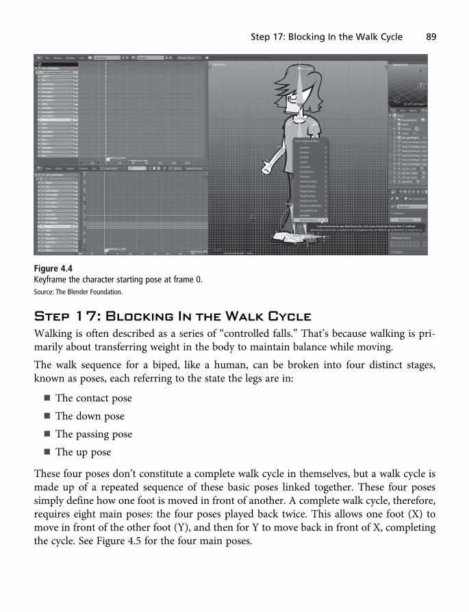
Figure 4.4Keyframe the character starting pose at frame 0.Source: The Blender Foundation.
Step 17: Blocking In the Walk CycleWalking is often described as a series of “controlled falls.” That’s because walking is pri-marily about transferring weight in the body to maintain balance while moving.
The walk sequence for a biped, like a human, can be broken into four distinct stages,known as poses, each referring to the state the legs are in:
n The contact pose
n The down pose
n The passing pose
n The up pose
These four poses don’t constitute a complete walk cycle in themselves, but a walk cycle ismade up of a repeated sequence of these basic poses linked together. These four posessimply define how one foot is moved in front of another. A complete walk cycle, therefore,requires eight main poses: the four poses played back twice. This allows one foot (X) tomove in front of the other foot (Y), and then for Y to move back in front of X, completingthe cycle. See Figure 4.5 for the four main poses.
Step 17: Blocking In the Walk Cycle 89
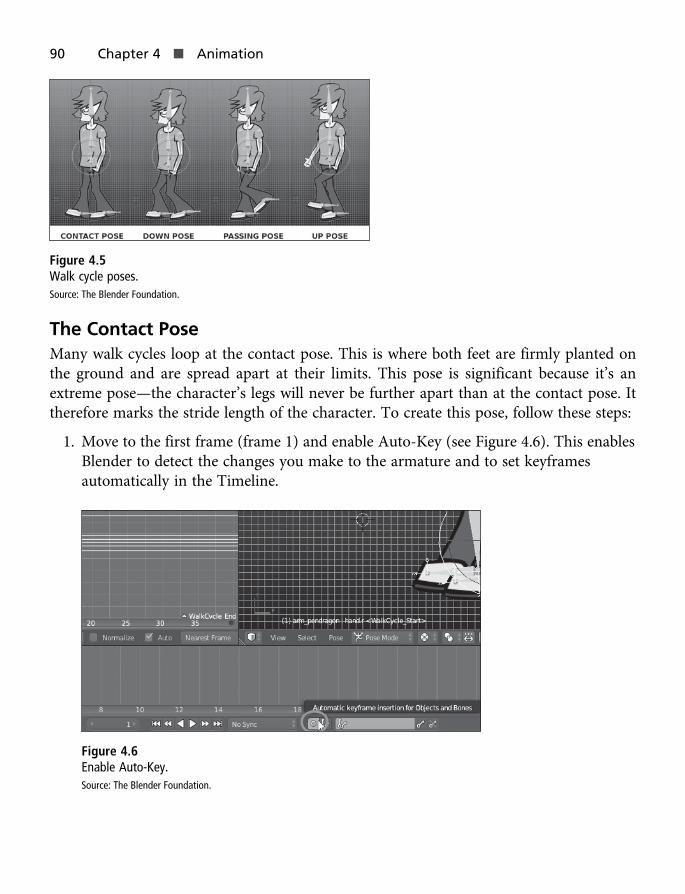
Figure 4.5Walk cycle poses.Source: The Blender Foundation.
The Contact PoseMany walk cycles loop at the contact pose. This is where both feet are firmly planted onthe ground and are spread apart at their limits. This pose is significant because it’s anextreme pose—the character’s legs will never be further apart than at the contact pose. Ittherefore marks the stride length of the character. To create this pose, follow these steps:
1. Move to the first frame (frame 1) and enable Auto-Key (see Figure 4.6). This enablesBlender to detect the changes you make to the armature and to set keyframesautomatically in the Timeline.
Figure 4.6Enable Auto-Key.Source: The Blender Foundation.
90 Chapter 4 n Animation

2. In Pose mode, pose the character’s legs and arms in the contact pose. Remember, thecharacter will move along at a constant and steady pace between frames 1 and 33. Sothe first contact pose is at frame 1, with the right foot forward and the left foot back.
3. For a complete walk cycle, you will need two more contact poses. The second is atframe 17, with the left leg forward and the right leg back—a mirror of the firstcontact pose. We’ll discuss this pose in a moment. The third is at frame 33, which isidentical to the first pose. To create the third pose, use the Dope Sheet to draw a boxselection around all keys for the contact pose at frame 1 and then duplicate theselected keys by pressing Ctrl+D or selecting Key > Duplicate from the menu.(See Figure 4.7.) Then drag the duplicated keys to frame 33 and click the mouse orpress Enter to insert them. This creates a duplicate set of keys for the final frame,so the poses at frame 1 and 33 are identical. (See Figure 4.8.)
Figure 4.7Duplicating keys.Source: The Blender Foundation.
Step 17: Blocking In the Walk Cycle 91

Figure 4.8Using key duplication to create the start and end contact poses.Source: The Blender Foundation.
4. The remaining contact pose occurs at frame 17. To create this, duplicate frame 1again and move the duplicate to frame 17. But as mentioned, this should be a mirrorof the pose in frame 1, with the left leg forward and the right leg back. To achievethis, select the right leg and move it back, and select the left leg and move it forward,allowing Inverse Kinematics to handle leg rotation and bending. Be sure to keep thesame distance between the legs as with the first and last contact poses to maintain thestride length. Assuming Auto-Key is enabled, Blender will update your keyframes torecord the new pose. (See Figure 4.9.)
92 Chapter 4 n Animation
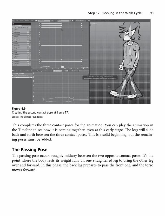
Figure 4.9Creating the second contact pose at frame 17.Source: The Blender Foundation.
This completes the three contact poses for the animation. You can play the animation inthe Timeline to see how it is coming together, even at this early stage. The legs will slideback and forth between the three contact poses. This is a solid beginning, but the remain-ing poses must be added.
The Passing PoseThe passing pose occurs roughly midway between the two opposite contact poses. It’s thepoint where the body rests its weight fully on one straightened leg to bring the other legover and forward. In this phase, the back leg prepares to pass the front one, and the torsomoves forward.
Step 17: Blocking In the Walk Cycle 93

To create this pose between frame 1 and frame 17, follow these steps:
1. With Auto-Key enabled, move the playhead to frame 9 and position the left leg topass the right, as shown in Figure 4.10. This pose should match the passing poseshown in Figure 4.5.
Figure 4.10Creating the passing pose.Source: The Blender Foundation.
2. Duplicate the passing pose keyframes at frame 9 and then move the duplicates toframe 25 to create the second passing pose between the contact poses at frames 17and 33. Then reverse the positions of the legs. As shown in Figure 4.11, the right legshould be passing at frame 17 instead of the left leg.
94 Chapter 4 n Animation

Figure 4.11Creating the second passing pose.Source: The Blender Foundation.
The Down PoseThe down pose occurs roughly midway between the contact pose at frame 1 and the pass-ing pose at frame 9. In the down pose, the body is preparing to transfer weight. Both ofthe character’s knees bend slightly before he stands straight on one leg and lifts the otherfrom the ground.
The down pose, along with the up pose (discussed next), is important for conveying theweight of your character. Exaggerated down poses make the character seem bulkier,heavier, sleepier, or lazier as he moves. Because Pendragon is a lazy and carefree character,his down pose should be fairly pronounced. To set the down pose, follow these steps:
1. Move the playhead to frame 5 and transform the armature bones to re-create thedown pose shown in Figure 4.5. For this pose, both feet should planted on theground, and the hip bone lowered and brought forward. It should look somethinglike Figure 4.12.
Step 17: Blocking In the Walk Cycle 95

Figure 4.12Creating the first down pose.Source: The Blender Foundation.
2. As with the contact and passing poses, you must duplicate the down pose and adaptit to work for the second half of the cycle, where the right leg passes the left. Thesecond down pose should occur at frame 21, between the second contact pose atframe 17 and the second passing pose at frame 25. See Figure 4.13.
96 Chapter 4 n Animation

Figure 4.13Creating the second down pose, reversing the leg positioning from the first down pose.Source: The Blender Foundation.
The Up PoseThe up pose first happens at frame 13, between the first passing pose at frame 9 and thesecond contact pose at frame 17. The up pose is the point where the trailing leg has passedand is coming down into contact with the ground. As this happens, the body raisesslightly to transfer the weight from one side to the other.
Like the down pose, the up pose is significant in conveying the weight or mood of thecharacter. Whereas the down pose can be exaggerated to express heaviness, slowness,and laziness, the up pose can be exaggerated to convey lightness, speed, and happiness.
Step 17: Blocking In the Walk Cycle 97
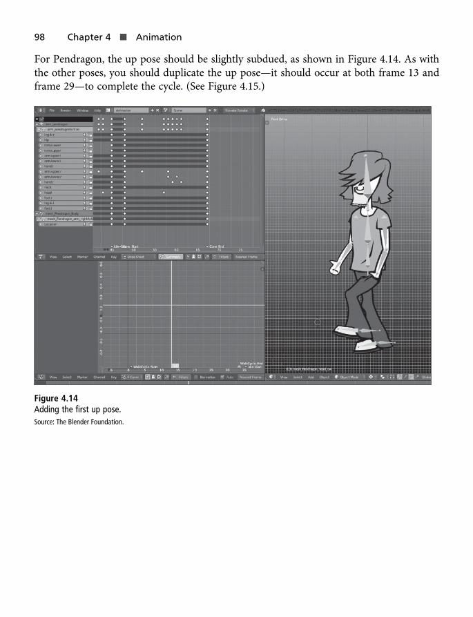
For Pendragon, the up pose should be slightly subdued, as shown in Figure 4.14. As withthe other poses, you should duplicate the up pose—it should occur at both frame 13 andframe 29—to complete the cycle. (See Figure 4.15.)
Figure 4.14Adding the first up pose.Source: The Blender Foundation.
98 Chapter 4 n Animation
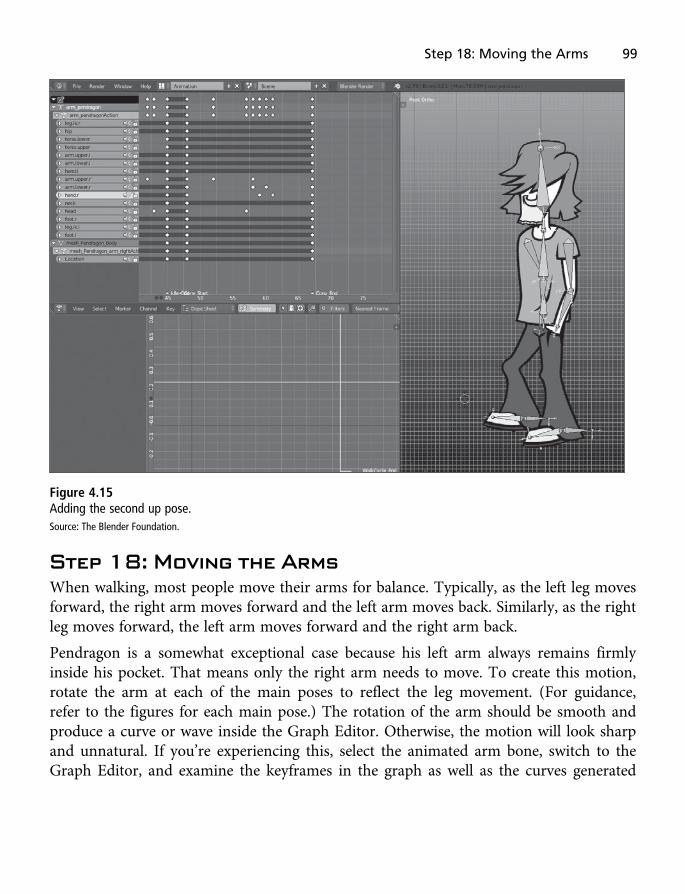
Figure 4.15Adding the second up pose.Source: The Blender Foundation.
Step 18: Moving the ArmsWhen walking, most people move their arms for balance. Typically, as the left leg movesforward, the right arm moves forward and the left arm moves back. Similarly, as the rightleg moves forward, the left arm moves forward and the right arm back.
Pendragon is a somewhat exceptional case because his left arm always remains firmlyinside his pocket. That means only the right arm needs to move. To create this motion,rotate the arm at each of the main poses to reflect the leg movement. (For guidance,refer to the figures for each main pose.) The rotation of the arm should be smooth andproduce a curve or wave inside the Graph Editor. Otherwise, the motion will look sharpand unnatural. If you’re experiencing this, select the animated arm bone, switch to theGraph Editor, and examine the keyframes in the graph as well as the curves generated
Step 18: Moving the Arms 99

between the frames. If the graph looks sharp and jagged, consider changing the interpola-tion mode to Bezier. (To do this, select all arm keyframes. Then Ctrl-right click the framesand choose Bezier from the menu that appears, as shown in Figure 4.16.)
Figure 4.16Tweaking keyframe interpolation for smoother motion.Source: The Blender Foundation.
ConclusionPendragon’s looping walk cycle is now complete. Excellent work! In reaching this faryou’ve seen a comprehensive workflow for creating animated 2D characters usingBlender. The main limitation of this method, as you may have noticed, is that it doesn’twork so well for animations in perspective. That is, you can easily create characters from aside or three-quarters view who must walk from side to side (left and right), but you can’tso successfully implement a character facing the camera who walks toward you or away.To create the latter, you’ll typically need to draw out each frame or else be especiallycreative about how you apply the method given here. But for most 2D cutout animation,the method detailed here can serve you well—particularly for walks, runs, jumps, sits,idles, conversations, and other kinds of actions, too.
100 Chapter 4 n Animation

Chapter 5
Exporting and Testing
The Pendragon character is now completely modeled, textured, rigged, and animated.Now it’s time to export him, complete with all appropriate data, from Blender into agame engine ready for inclusion in a real-time game. At this stage, there are many gameengines a developer could choose, including the Unreal Engine, Leadwerks, Shiva, Godot,and plenty more. For this eBook, I’ll choose the Unity engine, demonstrating how to opti-mally export Pendragon from Blender to Unity, including animation data. (See Figure 5.1.)So let’s go!
101

Figure 5.1Preparing the Pendragon model for export.Source: The Blender Foundation.
Note
The completed Pendragon model, including rigging and animation, is included in the eBook companion files inthe Chapter05 folder. You can open the file and follow with this chapter, if you prefer.
Step 19: Exporting Objects from BlenderUnity supports several mesh formats for import. Indeed, you can make models and scenesin many formats—including MAX, MB, Blend, and more—and then import them effec-tively into Unity. Not all formats and workflows are created equal for in-game perfor-mance, however. Consequently, you must take special care when choosing a file formatfor exporting animated models from Blender.
102 Chapter 5 n Exporting and Testing

So which file format should you use? Well, one you shouldn’t use is the native Blendformat. It’s likely to contain additional, Blender-specific data that Unity simply doesn’tunderstand or use, which is simply inefficient. Instead, export your models using eitherthe Autodesk FBX format or the Open Standard DAE format. Both formats work withUnity and offer finer control over the kind of data Blender exports with your meshfiles. This section explores mesh export with the popular and widely supported FBXformat.
1. Select all mesh parts for Pendragon (head, legs, arms, etc.) and the animatedarmature. These objects represent the items to be exported. (You don’t needto export objects like cameras, lamps, empties, references planes, and otherhelpers.)
2. Move the animation playhead in the Timeline to frame 1 (the start frame).
3. Ensure the animation end frame is set correctly. It should reflect the true, lastframe of animation in the sequence. The Blender FBX Exporter uses the endframe value to determine the total amount of animation data to export to theFBX File.
4. Choose File > Export > Autodesk FBX. (See Figure 5.2.)
5. The FBX Exporter displays many options for controlling how the FBX file isexported, enabling you to include or exclude specific data from the scene. To exportan animated character that’s selected in the scene, configure the FBX Exporter asfollows (see Figure 5.3):
n Select the Selected Objects checkbox to limit the export to only the selected objectsin this scene. In this way, you avoid exporting unnecessary data.
n Shift-click the Armature and Mesh options. This enables you to export botharmature and mesh objects. The armature is exported as bones, which featureimportant animation and structural data for your model.
Step 19: Exporting Objects from Blender 103

n Select the Apply Modifiers checkbox to bake all modifier data into the mesh that’sexported. This process works nondestructively. That is, after export, your meshdata in the Blender scene will remain unchanged.
n Select the Include Animation and Optimize Keyframes checkboxes.
Figure 5.2Accessing the Blender FBX Exporter.Source: The Blender Foundation.
104 Chapter 5 n Exporting and Testing

Figure 5.3Using the FBX Exporter to export an animated mesh.Source: The Blender Foundation.
6. After you set these options, click the Export FBX button in the top-right area of theExport FBX dialog box.
Step 19: Exporting Objects from Blender 105
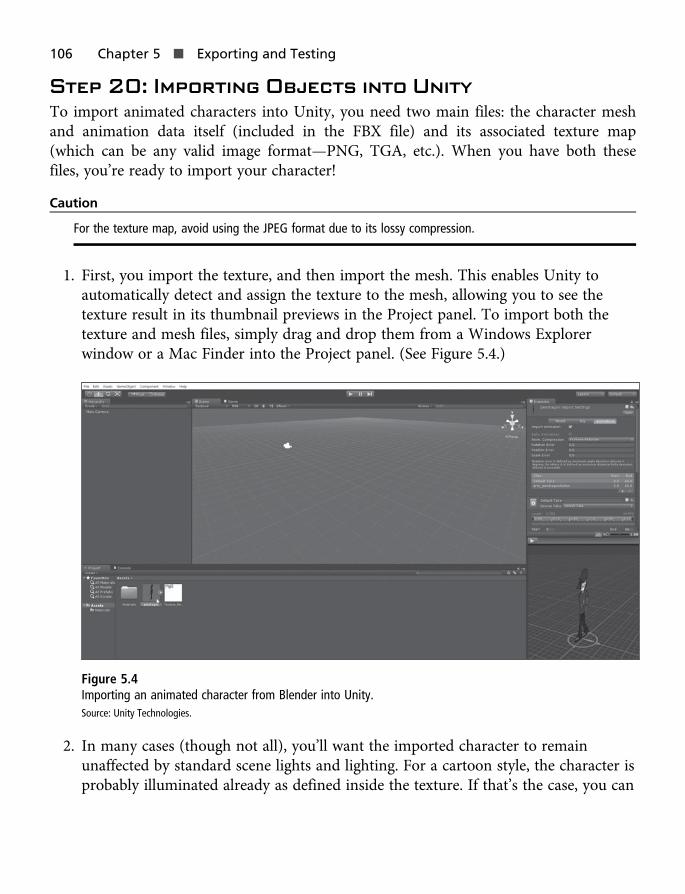
Step 20: Importing Objects into UnityTo import animated characters into Unity, you need two main files: the character meshand animation data itself (included in the FBX file) and its associated texture map(which can be any valid image format—PNG, TGA, etc.). When you have both thesefiles, you’re ready to import your character!
Caution
For the texture map, avoid using the JPEG format due to its lossy compression.
1. First, you import the texture, and then import the mesh. This enables Unity toautomatically detect and assign the texture to the mesh, allowing you to see thetexture result in its thumbnail previews in the Project panel. To import both thetexture and mesh files, simply drag and drop them from a Windows Explorerwindow or a Mac Finder into the Project panel. (See Figure 5.4.)
Figure 5.4Importing an animated character from Blender into Unity.Source: Unity Technologies.
2. In many cases (though not all), you’ll want the imported character to remainunaffected by standard scene lights and lighting. For a cartoon style, the character isprobably illuminated already as defined inside the texture. If that’s the case, you can
106 Chapter 5 n Exporting and Testing

disable scene lighting for the character material, making it self-illuminated. To do so,select the character material in the Project panel and change its shader type fromDiffuse to Unlit > Texture, as shown in Figure 5.5. When you do, the character meshwill change appearance in the Preview panel, probably appearing brighter.
Figure 5.5Tweaking the character shader to be self-illuminated.Source: Unity Technologies.
Step 20: Importing Objects into Unity 107

3. Select the Pendragon mesh in the Project panel and click the right-pointing arrow onthe mesh thumbnail. This expands the mesh contents to show all the importedcomponents, including all mesh pieces, the armature bone data, and the animationdata. (If one of these components is missing, return to Blender, select all the requiredobjects, and use the FBX Exporter to reimport the mesh.) The complete Pendragonmesh will look something like Figure 5.6 in Unity.
Figure 5.6Reviewing the imported mesh contents.Source: Unity Technologies.
4. The default Scale Factor setting for the Pendragon mesh, found in the ObjectInspector’s Model tab, will likely be 0.01. (See Figure 5.7.) This value is not what youwant for the mesh, however. Change the value from 0.01 to 1. Then drag and dropthe mesh into the active scene for test purposes. Ascertain whether its size is right foryour project, tweaking it as required by changing the Scale Factor setting in theObject Inspector. I settled on a Scale Factor of 8. Remember, the mesh you added tothe scene is simply a test object for adjusting the Scale Factor setting to a moresuitable value. When you’ve settled on a Scale Factor value, you can delete the object.
108 Chapter 5 n Exporting and Testing

Figure 5.7Changing the mesh’s Scale Factor setting.Source: Unity Technologies.
Step 21: Configuring the MeshNext, let’s tweak the mesh settings even further. Follow these steps:
1. On the Model tab, deselect the Import BlendShapes, Generate Colliders, andGenerate Lightmap UVs checkboxes. (See Figure 5.8.)
Step 21: Configuring the Mesh 109

Figure 5.8Configuring settings in the Model tab.Source: Unity Technologies.
2. If your mesh needs colliders, consider using collider primitives, available fromthe Component > Physics menu. These perform faster than mesh colliders.
3. Click the Rig tab. Then select Generic from the Animation Type drop-downlist. Leave all remaining settings at their defaults, as shown in Figure 5.9.
110 Chapter 5 n Exporting and Testing

Figure 5.9Configuring settings in the Rig tab.Source: Unity Technologies.
4. Click the Animation tab. In this tab, Unity enables you to carve up the Timelineincluded in the file into separate animations. You can then play and loop theseanimations individually within Unity. Chapter 4, “Animation,” discussed how tocreate a walk animation for Pendragon, but the Pendragon file imported here alsoincludes additional animations, such as a talk animation and an idle animation.These animations are included on the same animation Timeline. To define thecomplete walk cycle created in Chapter 4, enabling Unity to recognize it as a singleanimation sequence, start by selecting the default take in the Animation tab to showthe animation settings in the file. (See Figure 5.10.)
Step 21: Configuring the Mesh 111

Figure 5.10Previewing animation data.Source: Unity Technologies.
5. The complete Timeline included in the file spans from frames 0 to 66, but the walk-cycle animation is only a subset of these frames. The first frame of the walk cycle is1 and the last fame is 33. Based on this, specify the start frame as 1 and the endframe as 32, not 33. This is because the animation must loop, repeating the firstframe once completed. If frame 33, which is identical to frame 1, were included in thecycle, there would be a noticeable and undesirable pause where the two duplicateframes are played in sequence.
112 Chapter 5 n Exporting and Testing

6. Select the Loop Time checkbox to mark the animation as a looping cycle. Figure 5.11shows the settings for the walk animation.
Figure 5.11Defining the walk animation.Source: Unity Technologies.
7. Click the Play button in the Object Inspector Preview panel to see the animationsequence in real time and make sure it looks as you intended.
8. If the animation looks as you intended, click the Apply button in the ObjectInspector to save your changes. These changes are not written to the original FBXfile, but are included in Unity-specific files as metadata for the asset. (If you need torevert to the original file, simply click the Revert button.)
Step 21: Configuring the Mesh 113

As mentioned, in addition to the walk cycle, the Pendragon mesh also features a conver-sation animation and an idle animation. The conversation animation should play on aloop when Pendragon is speaking, and the idle animation should play when he’s standingstill. The idle animation spans frames 35 to 45, and the conversation animation spansframes 48 to 67. To configure the idle animation, follow these steps:
1. Click the plus (+) icon to create a new animation clip.
2. In the Source Box, type Idle to name the animation clip. (See Figure 5.12.)
Figure 5.12Creating a new animation clip for the idle animation.Source: Unity Technologies.
3. Repeat the steps you performed with the walk animation, but change the start andend frames to 35 and 44, respectively. (Again, you must subtract 1 from the endframe to maintain a smooth looping cycle.)
To configure the conversation animation, repeat these steps, but name the clip “Conversa-tion” and change the start and end frames to 48 and 65, respectively. Figure 5.13 shows allthree animations—walk, idle, and conversation.
114 Chapter 5 n Exporting and Testing

Figure 5.13Creating the idle and conversation animations.Source: Unity Technologies.
When you’ve created the animation clips for the Pendragon character, click Apply to savethe changes. You can confirm that the animation clips have been added to the mesh byexpanding it in Project panel and viewing its constituent pieces. In addition to the meshand armature data, it should now contain animation clips—one clip for each separate andindependent animation. (See Figure 5.14.)
Step 21: Configuring the Mesh 115

Figure 5.14Mesh with animations added.Source: Unity Technologies.
Step 22: Testing the MeshHere comes the moment of truth—the part where you test the animated mesh in-game tosee how it works. Follow these steps:
1. In Unity, drag and drop the character mesh into the scene and position it in viewof the scene camera (or else move the camera), as shown in Figure 5.15.
Figure 5.15Adding a character mesh to the scene.Source: Unity Technologies.
116 Chapter 5 n Exporting and Testing

2. The default scene camera is configured as a perspective camera, which means itsrendering feature set is optimized for 3D scenes and objects rather than 2D ones.You can fix this manually by using an orthographic camera, configured to a scale of1 world unit to 1 pixel. To do this, first select the camera and change its Projectionsetting to Orthographic.
3. Set the Target Resolution in the Game tab toolbar to full HD (1920×1080) andchange the Size setting in the Camera panel to 540 (which is half the verticalresolution—that is, 1,080/2). Note that you may need to scale up the Pendragoncharacter to improve his visibility in the viewport. (See Figure 5.16.)
Figure 5.16Viewing the 2D character from an orthographic camera.Source: Unity Technologies.
4. You now have a “pixel perfect” view of the character onscreen. But if you clickPlay on the toolbar to run the game, you’ll see the character remains static andmotionless. The animations simply don’t play. To fix this, you need to create aMecanim state machine asset. To do so, right-click in the Unity Project panel andchoose Create > Animator Controller, as shown in Figure 5.17. This creates a newGraph or State Machine asset in the project. This defines which animation shouldplay on the character mesh in the level.
Step 22: Testing the Mesh 117

Figure 5.17Creating an Animator Controller in the Unity project.Source: Unity Technologies.
5. To view and edit the newly created Animator Controller asset, choose Window >Animator to open a new Animator window. Then double-click the AnimatorController asset in the Project panel to open it inside the Animator window. Thiswindow displays the contents of the Animator Controller. By default, the controllerfeatures only one node (or state), named “Any State.” On its own, this state will haveno appreciable effect on the Pendragon mesh in the scene. (See Figure 5.18.)
118 Chapter 5 n Exporting and Testing

Figure 5.18The animation graph with a default state.Source: Unity Technologies.
6. To get the animation working for the Pendragon mesh, expand the mesh characterpieces in the Project panel as before, by clicking the right-pointing arrow on themesh thumbnail.
7. Click and drag the walk animation state from the mesh asset and drop it into theanimation graph. The newly added animation appears as a state in the graph and ishighlighted orange to indicate that it’s the default state—that is, the state that willplay automatically as gameplay begins. (See Figure 5.19.) If the animation doesn’tappear in orange, right-click the state and choose Set As Default.
Step 22: Testing the Mesh 119

Figure 5.19Setting the walk animation as the default state for the character.Source: Unity Technologies.
8. The animation controller is now configured to play the walk animation as the gamebegins. To assign this controller to the Pendragon mesh in the scene, select themesh and then drag and drop the animation controller asset from the Project panelinto the Controller field for the Animator component in the Object Inspector.(See Figure 5.20.)
120 Chapter 5 n Exporting and Testing

Figure 5.20Assigning the animation controller to the character.Source: Unity Technologies.
9. Run the game and watch the walk animation at work on the character in theviewport! Excellent work. You’ve just completed your first animated, real-time gamecharacter using a Blender-to-Unity workflow! (See Figure 5.21.)
Step 22: Testing the Mesh 121

Figure 5.21The character, up and running in Unity.Source: Unity Technologies.
Note
The completed Unity project with an animated character can be found in the eBook companion files, in theChapter05 folder.
ConclusionYou’ve come to the end of this course! In reaching this point, you’ve created an animated,game-compliant 2D character using a professional-grade workflow in Blender, acompletely free application. The Pendragon character has been modeled, textured andUV-mapped, rigged, and animated to run a loopable walk-cycle that can be reused forany 2D character fitting the Pendragon armature. This character not only has the abilityto move and rotate its limbs, like its arms and legs, but the limbs can deform and bend ina believable way.
122 Chapter 5 n Exporting and Testing

Of course, in a short eBook such as this, it’s not possible to cover every aspect of 2Danimation. There’s simply too much information for even the largest of books. But thiseBook does get you going in the right direction on a strong foundation that supports areliable workflow. Even more important, the workflow covered here is abstract and trans-ferable, enabling you to rig and animate your own characters—even in other 3D tools thatoffer equivalent features to Blender. So with that said, I wish you every success in your 2Dcharacter creation adventures!
Conclusion 123