ragnarok architectural
TRANSCRIPT
Ragnarok:
An
Architecture
Based
Software Development Environment
Henrik B�rbak Christensen
Centre for Experimental System Development
Department of Computer Science
University of Aarhus
DK-8000 �Arhus C, Denmark
February, 1999

ii
To my wife, Susanne,
and my sons, Mikkel and Magnus.
iii

iv
Acknowledgements
First of all, my best thanks to Ole Lehrmann Madsen for being an enthusiastic
and supportive supervisor with a great sense of humour. Also, thank you for
your advice about how to handle being a researcher and a father at the same
time|some of them, I have found a constant source of amusement: How did you
ever manage to balance a kid on your legs and read articles at the same time?
I am also greatly indebted to Erik Meineche Schmidt who gave me the chance
of getting back into academia, and for providing guidance during the �rst time.
Steve Reiss gave me the chance to meet United States and Brown University
as visiting researcher, and beat me into focusing more on model than on system.
Special thanks to the guys who have used (especially in the start, \endured"
may be a better word) Ragnarok the last couple of years: The ConSys team:
Torben Worm, Karsten Telling Nielsen, and J�rgen S. Nielsen, and later the
BETA compiler team: Ole Lehrmann Madsen, Morten Groule�, Peter Andersen,
and Henrik R�n.
The Devise group has been a wonderful group to be part of and has provided
much needed information in many situations, in particular Morten Groule�, Henry
Michael Lassen, Lennerth Sloth, Peter Andersen, and J�rgen Lindskov Knudsen.
I have had many valuable and rewarding discussions with Boris Magnusson, Ulf
Asklund, and Lars Bendix. Also thanks to Olav W. Bertelsen, and Kresten Krab
Thorup for reviewing earlier article drafts. Thanks to Andre van Hoek for some
good, critical, email discussions. Ole Lehrmann Madsen and Henrik R�n read
earlier drafts of this thesis and provided many valuable comments. Gudmund
Skovbjerg Frandsen provided valuable comments on the formal description in
chapter 3.
Mads Torgersen suggested the topography aspect of Ragnarok and Klaus
Marius Hansen originally suggested the Ragnarok name itself.
Finally, I would like to thank my two sons, Mikkel and Magnus, and my wife,
Susanne, for enduring periods of absence and reduced income just for me to pursue
some \crazy" ideas and three letters on my business card.
v
Note: Due to technical problems with our colour printer,
the pages in chapter 4 that contain colour images could
not be printed on both sides. As a result, some pages are
unfortunately left blank.
vi

Contents
1 Introduction 1
1.1 Vision . . . . . . . . . . . . . . . . . . . . . . . . . . . . . . . . . . 2
1.2 Hypotheses . . . . . . . . . . . . . . . . . . . . . . . . . . . . . . . 3
1.2.1 Project Management . . . . . . . . . . . . . . . . . . . . . . 3
1.2.2 Management of Evolution . . . . . . . . . . . . . . . . . . . 4
1.2.3 Comprehension and Navigation . . . . . . . . . . . . . . . . 4
1.2.4 Discussion . . . . . . . . . . . . . . . . . . . . . . . . . . . . 5
1.3 Contributions . . . . . . . . . . . . . . . . . . . . . . . . . . . . . . 5
1.3.1 Architectural Software Con�guration Management . . . . . 6
1.3.2 Geographic Space Architecture Visualisation . . . . . . . . 6
1.3.3 List of Publications . . . . . . . . . . . . . . . . . . . . . . 6
1.3.4 Prototypes . . . . . . . . . . . . . . . . . . . . . . . . . . . 8
1.4 Structure of Thesis . . . . . . . . . . . . . . . . . . . . . . . . . . . 9
2 Software Architecture 11
2.1 A Model of Architecture . . . . . . . . . . . . . . . . . . . . . . . . 12
2.1.1 Software Component . . . . . . . . . . . . . . . . . . . . . . 12
2.1.2 Substance . . . . . . . . . . . . . . . . . . . . . . . . . . . . 13
2.1.3 Relations . . . . . . . . . . . . . . . . . . . . . . . . . . . . 14
2.1.4 Graph Interpretation . . . . . . . . . . . . . . . . . . . . . . 15
2.2 Annotated Architecture . . . . . . . . . . . . . . . . . . . . . . . . 16
2.2.1 Annotations . . . . . . . . . . . . . . . . . . . . . . . . . . . 16
2.2.2 Annotation Synthesis . . . . . . . . . . . . . . . . . . . . . 16
2.2.3 Status . . . . . . . . . . . . . . . . . . . . . . . . . . . . . . 17
2.3 Discussion . . . . . . . . . . . . . . . . . . . . . . . . . . . . . . . . 17
2.3.1 Logical versus Physical Structure . . . . . . . . . . . . . . . 17
2.3.2 Derived Objects . . . . . . . . . . . . . . . . . . . . . . . . 17
2.3.3 Architectural Views . . . . . . . . . . . . . . . . . . . . . . 18
3 Architectural Software Con�guration Management 19
3.1 Motivation and Proposal . . . . . . . . . . . . . . . . . . . . . . . . 20
3.2 Architectural Model, Static Aspects . . . . . . . . . . . . . . . . . 21
3.2.1 Basic Elements and Domains . . . . . . . . . . . . . . . . . 22
3.2.2 Software Component Version . . . . . . . . . . . . . . . . . 22
3.2.3 Component . . . . . . . . . . . . . . . . . . . . . . . . . . . 24
3.2.4 Con�guration . . . . . . . . . . . . . . . . . . . . . . . . . . 24
vii
3.2.5 Version Group . . . . . . . . . . . . . . . . . . . . . . . . . 26
3.2.6 Example . . . . . . . . . . . . . . . . . . . . . . . . . . . . . 26
3.3 Architectural Model, Dynamic Aspects . . . . . . . . . . . . . . . . 27
3.3.1 Repository . . . . . . . . . . . . . . . . . . . . . . . . . . . 27
3.3.2 Workspace . . . . . . . . . . . . . . . . . . . . . . . . . . . 28
3.3.3 Project . . . . . . . . . . . . . . . . . . . . . . . . . . . . . 28
3.3.4 Revise . . . . . . . . . . . . . . . . . . . . . . . . . . . . . . 28
3.3.5 Create . . . . . . . . . . . . . . . . . . . . . . . . . . . . . . 29
3.3.6 Check-in . . . . . . . . . . . . . . . . . . . . . . . . . . . . . 29
3.3.7 Check-out . . . . . . . . . . . . . . . . . . . . . . . . . . . . 31
3.4 Model Properties . . . . . . . . . . . . . . . . . . . . . . . . . . . . 32
3.4.1 Versions are Con�gurations are Versions... . . . . . . . . . . 32
3.4.2 Architectural Di�erences . . . . . . . . . . . . . . . . . . . . 33
3.4.3 Mixed Con�gurations . . . . . . . . . . . . . . . . . . . . . 33
3.5 Branching and Merging Architectures . . . . . . . . . . . . . . . . 35
3.5.1 Architectural Evolution . . . . . . . . . . . . . . . . . . . . 36
3.5.2 Parallel Development . . . . . . . . . . . . . . . . . . . . . 37
3.5.3 Overlapping Con�gurations . . . . . . . . . . . . . . . . . . 40
3.6 Tailorability . . . . . . . . . . . . . . . . . . . . . . . . . . . . . . . 41
3.6.1 Reporting . . . . . . . . . . . . . . . . . . . . . . . . . . . . 41
3.6.2 Triggers . . . . . . . . . . . . . . . . . . . . . . . . . . . . . 42
3.7 Implementation Issues . . . . . . . . . . . . . . . . . . . . . . . . . 42
3.7.1 Design Rationale . . . . . . . . . . . . . . . . . . . . . . . . 42
3.7.2 Design . . . . . . . . . . . . . . . . . . . . . . . . . . . . . . 44
3.7.3 Deleting Component Versions . . . . . . . . . . . . . . . . . 44
3.8 RCM Prototype Outline . . . . . . . . . . . . . . . . . . . . . . . . 45
3.8.1 Interface Basics . . . . . . . . . . . . . . . . . . . . . . . . . 46
3.8.2 Navigation and Reporting . . . . . . . . . . . . . . . . . . . 46
3.8.3 Development . . . . . . . . . . . . . . . . . . . . . . . . . . 46
3.8.4 Reconstructing Con�gurations . . . . . . . . . . . . . . . . 48
3.8.5 Architectural Di�erences . . . . . . . . . . . . . . . . . . . . 48
3.9 Case Studies . . . . . . . . . . . . . . . . . . . . . . . . . . . . . . 49
3.9.1 ConSys Project . . . . . . . . . . . . . . . . . . . . . . . . . 49
3.9.2 BETA Compiler Project . . . . . . . . . . . . . . . . . . . . 49
3.9.3 Ragnarok Project . . . . . . . . . . . . . . . . . . . . . . 50
3.9.4 Interviews . . . . . . . . . . . . . . . . . . . . . . . . . . . . 50
3.9.5 Usage Statistics . . . . . . . . . . . . . . . . . . . . . . . . . 52
3.9.6 Tailorability Usage . . . . . . . . . . . . . . . . . . . . . . . 54
3.9.7 Annotation Usage . . . . . . . . . . . . . . . . . . . . . . . 55
3.9.8 Summary . . . . . . . . . . . . . . . . . . . . . . . . . . . . 55
3.10 Discussion . . . . . . . . . . . . . . . . . . . . . . . . . . . . . . . . 57
3.10.1 Classifying the Version Model . . . . . . . . . . . . . . . . . 58
3.10.2 The Intermediate Version Debate . . . . . . . . . . . . . . . 58
3.10.3 Pollution by Intermediate Versions . . . . . . . . . . . . . . 60
3.10.4 On Development Process . . . . . . . . . . . . . . . . . . . 60
3.10.5 On Variants . . . . . . . . . . . . . . . . . . . . . . . . . . . 62
3.10.6 On Build Management . . . . . . . . . . . . . . . . . . . . . 64
3.10.7 Architecture Quality is SCM Quality . . . . . . . . . . . . . 64
viii
3.10.8 Scaling Up . . . . . . . . . . . . . . . . . . . . . . . . . . . 65
3.10.9 Relation Types . . . . . . . . . . . . . . . . . . . . . . . . . 65
3.10.10Impact of Changes . . . . . . . . . . . . . . . . . . . . . . . 66
3.10.11Shadow Problem . . . . . . . . . . . . . . . . . . . . . . . . 66
3.11 Related Work . . . . . . . . . . . . . . . . . . . . . . . . . . . . . . 67
3.11.1 COOP/Orm . . . . . . . . . . . . . . . . . . . . . . . . . . 67
3.11.2 POEM . . . . . . . . . . . . . . . . . . . . . . . . . . . . . . 68
3.11.3 CVS . . . . . . . . . . . . . . . . . . . . . . . . . . . . . . . 68
3.11.4 ClearCase . . . . . . . . . . . . . . . . . . . . . . . . . . . . 69
3.11.5 Adele . . . . . . . . . . . . . . . . . . . . . . . . . . . . . . 70
3.12 Future Work . . . . . . . . . . . . . . . . . . . . . . . . . . . . . . 71
3.12.1 Dimensions of Versioning . . . . . . . . . . . . . . . . . . . 71
3.12.2 Improved Collaborative Support . . . . . . . . . . . . . . . 72
3.12.3 Branching Consistency . . . . . . . . . . . . . . . . . . . . . 72
3.12.4 Disconnected Operation . . . . . . . . . . . . . . . . . . . . 73
3.12.5 Softening Project Boundaries . . . . . . . . . . . . . . . . . 74
3.12.6 Shared Versions . . . . . . . . . . . . . . . . . . . . . . . . . 74
3.12.7 Cyclic Relations . . . . . . . . . . . . . . . . . . . . . . . . 75
4 Geographic Space Architecture Visualisation 79
4.1 Motivation . . . . . . . . . . . . . . . . . . . . . . . . . . . . . . . 80
4.2 Human Navigation and Spatial Metaphors . . . . . . . . . . . . . . 81
4.3 Proposal . . . . . . . . . . . . . . . . . . . . . . . . . . . . . . . . . 82
4.4 Visualisation Model . . . . . . . . . . . . . . . . . . . . . . . . . . 83
4.4.1 Landscape, Landmark, and Decoration . . . . . . . . . . . . 83
4.4.2 Maps . . . . . . . . . . . . . . . . . . . . . . . . . . . . . . 84
4.4.3 Aspects . . . . . . . . . . . . . . . . . . . . . . . . . . . . . 85
4.4.4 Correlation to Architecture . . . . . . . . . . . . . . . . . . 87
4.4.5 Interaction and Mediation . . . . . . . . . . . . . . . . . . . 87
4.4.6 Landscape Creation . . . . . . . . . . . . . . . . . . . . . . 88
4.4.7 Global Context . . . . . . . . . . . . . . . . . . . . . . . . . 89
4.4.8 Shared Landscape . . . . . . . . . . . . . . . . . . . . . . . 89
4.5 Model Properties . . . . . . . . . . . . . . . . . . . . . . . . . . . . 90
4.5.1 Geographical Organisation . . . . . . . . . . . . . . . . . . 90
4.5.2 Hierarchical Presentation . . . . . . . . . . . . . . . . . . . 91
4.5.3 Decoration . . . . . . . . . . . . . . . . . . . . . . . . . . . 91
4.5.4 Map Layer . . . . . . . . . . . . . . . . . . . . . . . . . . . 91
4.5.5 Mediation . . . . . . . . . . . . . . . . . . . . . . . . . . . . 91
4.5.6 Aspect Property . . . . . . . . . . . . . . . . . . . . . . . . 92
4.5.7 Shared Landscape Property . . . . . . . . . . . . . . . . . . 92
4.6 Prototype . . . . . . . . . . . . . . . . . . . . . . . . . . . . . . . . 93
4.6.1 Comprehension . . . . . . . . . . . . . . . . . . . . . . . . . 94
4.6.2 Topography . . . . . . . . . . . . . . . . . . . . . . . . . . . 94
4.6.3 Version Control . . . . . . . . . . . . . . . . . . . . . . . . . 95
4.6.4 Script Visualisation . . . . . . . . . . . . . . . . . . . . . . 96
4.7 Implementation . . . . . . . . . . . . . . . . . . . . . . . . . . . . . 97
4.7.1 Design . . . . . . . . . . . . . . . . . . . . . . . . . . . . . . 98
4.7.2 Landscape Resolution . . . . . . . . . . . . . . . . . . . . . 99
ix
4.8 Case Studies . . . . . . . . . . . . . . . . . . . . . . . . . . . . . . 99
4.8.1 Interview . . . . . . . . . . . . . . . . . . . . . . . . . . . . 99
4.8.2 Summary . . . . . . . . . . . . . . . . . . . . . . . . . . . . 102
4.9 Discussion . . . . . . . . . . . . . . . . . . . . . . . . . . . . . . . . 103
4.9.1 A Cognitive Dimensions Evaluation . . . . . . . . . . . . . 104
4.9.2 Salience . . . . . . . . . . . . . . . . . . . . . . . . . . . . . 106
4.9.3 Positional Stability . . . . . . . . . . . . . . . . . . . . . . . 107
4.9.4 Other Architecture- and Project Views . . . . . . . . . . . . 108
4.9.5 Visualisation and Architectural Consistency . . . . . . . . . 108
4.9.6 The Captivating Third Dimension . . . . . . . . . . . . . . 109
4.10 The Potential of Geographic Space . . . . . . . . . . . . . . . . . . 110
4.10.1 Geographic Space for General Purpose Visualisation . . . . 110
4.10.2 To Work is to Be (Somewhere) . . . . . . . . . . . . . . . . 111
4.10.3 Geographical Interpretation of Link Enactment . . . . . . . 111
4.11 Related Work . . . . . . . . . . . . . . . . . . . . . . . . . . . . . . 112
4.11.1 CASE tools . . . . . . . . . . . . . . . . . . . . . . . . . . . 112
4.11.2 Pad . . . . . . . . . . . . . . . . . . . . . . . . . . . . . . . 113
4.11.3 SeeSoft . . . . . . . . . . . . . . . . . . . . . . . . . . . . . 113
4.11.4 SAAMtool . . . . . . . . . . . . . . . . . . . . . . . . . . . 113
4.11.5 Desktop Space Metaphors . . . . . . . . . . . . . . . . . . . 114
4.11.6 Spatialisation of Hypertext . . . . . . . . . . . . . . . . . . 115
4.12 Future Work . . . . . . . . . . . . . . . . . . . . . . . . . . . . . . 115
4.12.1 Visualising Relation Types . . . . . . . . . . . . . . . . . . 116
4.12.2 Visualising Architectural Reuse . . . . . . . . . . . . . . . . 116
4.12.3 Run-Time Aspect De�nition . . . . . . . . . . . . . . . . . 116
4.12.4 Semantic Zoom . . . . . . . . . . . . . . . . . . . . . . . . . 116
5 Bridging the Gap 119
5.1 Versioning the Landscape . . . . . . . . . . . . . . . . . . . . . . . 119
5.2 Visualising Versions . . . . . . . . . . . . . . . . . . . . . . . . . . 120
6 Conclusion 121
x
Dansk sammendrag
Denne afhandling omhandler Ragnarok projektet, et projekt indenfor det dat-
alogiske fagomr�ade software udviklingsomgivelser.
Den grundl�ggende vision i projektet er at frembringe modeller og metoder
til brug i software udviklingsomgivelser, som mindsker omkostningerne ved essen-
tielle aspekter af udviklingsprocessen, uden dette medf�rer v�sentlige omkost-
ninger i selve produktionen af softwaren.
Som grundlag for at opfylde denne vision opstilles en hovedhypotese:
Et softwaresystems logiske arkitektur er en st�rk og naturlig begreb-
sramme for h�andtering af v�sentlige aspekter af udviklingsprocessen.
Disse aspekter kan underst�ttes direkte i en arkitekturbaseret udvikling-
somgivelse.
Derved bliver begrebet `softwarearkitektur', specielt det logiske/designorienterede
aspekt, det centrale tema i Ragnarok.
Denne hovedhypotese konkretiseres i tre underhypoteser. Hver af disse under-
hypoteser retter sig mod konkrete aspekter af udviklingsprocessen:
Ad. Projekt styring: At indsamle og administrere data relateret til projek-
tets styring og organisation, f.eks. timeregistrering, fejlrapportering, budgetter-
ing, ressourceallokering, opgavefordeling, osv.
Hypotese 1: Den logiske softwarearkitektur kan annoteres med de data, der er
relevante for styring og implementering af softwaren.
Traditionelt h�andteres et design, og den organisatoriske struktur som er grund-
laget for designets implementation, af s�rskilte procedurer og v�rkt�jer, hvilket
leder til problemer med at holde disse to strukturer synkroniserede. Ved at be-
handle organisatoriske data som annoteringer af selve arkitekturen mindskes dette
problem.
Ad. Styring af historisk udvikling: At sikre sporbarhed og overblik over
projektets historiske udvikling generelt, og af projektet logiske arkitektur og
tilh�rende kildekode i s�rdeleshed.
Hypotese 2: Den logiske softwarearkitektur er en naturligt begrebsramme for
versions- og kon�gurationsstyring.
Traditionelle versions- og kon�gurationsstyringsv�rkt�jer tager udgangspunkt
i de fysiske �ler, som indeholder et softwareprojekts kildetekst. Det vil sige, at
`software' opfattes som en m�ngde af �ler, og ikke som en arkitektur. Dette
kr�ver, at udviklerne selv skal huske og overskue relationerne mellem design-
dom�net (arkitekturniveau) og kon�gurationsdom�net (�lniveau), hvilket er be-
sv�rligt og ofte leder til fejl. Ydermere kan en �lm�ngde ikke direkte udtrykke
�ndringer p�a arkitekturniveau. Ved at benytte samme begrebsramme i begge
dom�ner l�ses disse problemer.
Ad. Overblik og navigation: At bidrage til at skabe overblik over projektets
dele og deres inbyrdes relationer; samt at �ge projektmedlemmernes evne til at
�nde relevant information i strukturen.
xi
Hypotese 3: Den logiske softwarearkitektur b�r v�re visuel h�andgribelig i et
geogra�sk organiseret `softwarelandskab'. Dette softwarelandskab b�r v�re centralt
i udviklingsomgivelsen; i kraft af at v�re f�lles for alle projektmedlemmer og i
kraft af at det medierer daglige aktiviteter.
Denne hypotese indeb�rer et forslag om at l�gge en geografisk, rumlig, metafor
til grund for visualisering af den logiske arkitektur, og benytte landkort til at ma-
nipulere og orientere sig i det derved fremkommende softwarelandskab. En geo-
grafisk stabil positionering af arkitektoniske entiteter g�r, at menneskets stedsans
kan udnyttes til gavn for overblik og navigationsevne. Ydermere er landskabet
f�lles for projektdeltagerne og mediere daglige opgaver mellem brugere og under-
liggende data, hvilket bidrager til, at landskabet skaber en f�lles forst�aelsesramme
og visualiserer projektudviklingen.
Store dele af disse forslag er indarbejdet i to prototyper: Ragnarok (inde-
holdende hypotese 2 og 3, og delvist 1) samt RCM (kun hypotese 2). Prototyperne
er blevet brugt i tre konkrete mindre- til mellemstore software udviklingsprojek-
ter over en periode p�a ca. tre �ar. Resultaterne fra studier af disse tre projekter,
indsamlet prim�rt gennem interview og sekund�rt gennem statistiske data fra
prototyperne selv, er f�lgende:
Arkitektonisk software kon�gurationsstyring er en anvendelig model for kon-
�gurationsstyring i et software projekt, i det mindste for mindre- til mellemstore
projekter. Modellen udm�rker sig ved sin naturlighed idet det benyttede begreb-
sapparat ligger t�t op ad det, som er velkendt for udviklerne. Modellens fokus
p�a bundne kon�gurationer fremh�ves; alts�a modellens fastholdelse, ikke kun af
versioner af en abstraktion, men af hele kon�gurationen, som abstraktionen tran-
sitivt udsp�nder via sine relationer til andre abstraktioner. Derved har modellen
ogs�a en iboende sporbarhed af arkitektonisk udvikling, idet �ndringer i relationer
mellem abstraktioner er fastholdte. En ofte fremf�rt kritik af kon�gurationsmod-
eller der, som denne, er baseret p�a version-f�rst udv�lgelse (version �rst selection),
er problemet med `mellemversioner' (version proliferation), hvis antal forventes
at eksplodere kombinatorisk. Et v�sentligt delresultat i afhandlingen er, at data
fra de tre Ragnarok projekter tilbageviser denne kritik, idet forholdet mellem
mellemversioner og versioner med substantielle �ndringer er konstant over tid.
Geogra�sk baseret arkitektur visualisering har vist sin anvendlighed i en r�kke
henseender. Modellen udm�rker sig prim�r ved forbedret navigationsevne, her-
ved forst�aet evnen til at �nde relevante dele af arkitekturen let og hurtigt. Lige-
ledes bidrager softwarelandskabet til overblik over dels arkitekturen som helhed,
dels over udvalgte aspekter af arkitekturens underliggende data (specielt versions-
kontrolaspekter i den foreliggende prototype). Landskabets egenskab af, at v�re
f�lles for alle projektdeltagere og dets visning af projektudviklingen (specielt
nye versioner og igangv�rende arbejde i den given prototype), udg�r et nyt-
tigt supplement til mundtlig kommunikation i teamet. En hypotetiseret fordel
ved modellen|at landskabet fremst�ar som et referenceramme for diskussion og
dokumentation|har dog endnu ikke kunne blive af- eller bekr�ftet ud fra det
udf�rte arbejde.
Annoteret software arkitektur er p.t. kun implementeret i meget begr�nset
omfang, og det er derfor endnu for tidligt at udtale sig om gyldigheden af den
opstillede hypotese.
xii
Sammenfattende mener vi, at resultatet af arbejdet st�tter hovedhypotesen:
At det logiske aspekt af software arkitektur er en god ramme for h�andtering
af processer og data i et software projekt. Mere vigtig er dog de opn�aede re-
sultater indenfor underhypoteserne, specielt de to hovedbidrag: Modellerne for
henholdsvis arkitektonisk software kon�gurationsstyring og for geogra�sk baseret
arkitektur visualisering. Selvom de er opst�aet i kraft af visionen bag Ragnarok,
er de selvst�ndige bidrag med bredere relevans ud over Ragnarok softwareud-
viklingsmilj�et selv.
xiii

xiv
Chapter 1
Introduction
The Ragnarok project is a research project within the �eld of software develop-
ment environments. The project belongs to the category `experimental computer
science', and the scienti�c method employed owes much to the tradition of physics
and astronomy: Problems are analysed, hypothetical solutions put forward, and
successively validated through experiments. In the Ragnarok context, it is cur-
rent problems in software engineering combined with personal experience from
large software development projects that are analysed. The analyses are basis for
proposing plausible solutions and proposing how to support these in a concrete
development environment. These proposals have been formulated as a small set
of hypotheses. To validate the hypotheses, a major e�ort has been invested in
the design and implementation of a prototype software development environment,
named Ragnarok, that has been continuously evaluated in realistic case studies.
The central theme in Ragnarok is the logical aspect of software architecture
which is explored as the principal framework for supporting concrete aspects
of the management of a software project and its data. As the �eld of software
development environments is a large �eld, focusing has been important. The main
focus and the main contributions in the Ragnarok project have been within the
�elds of software con�guration management and software visualisation.
A few words about the name: Ragnarok. Our research group has a tradi-
tion for naming software systems after gods and events in the Nordic mythology.
Ragnarok is named after mythological \Ragnarok" that denotes the last, cata-
clysmic, battle between gods and giants|a battle that destroys the known world.
There are two reasons for choosing this name: First, anyone how has been involved
1
in a hard-pressed development project knows the sensation of \Ragnarok", and
hopefully by introducing the Ragnarok environment the two may neutralise each
other. Secondly|by giving a development team Ragnarok, I have promised no
more than I am able to keep. . .
1.1 Vision
A major source of inspiration for the current work has been personal experiences
as chief architect and implementor of a large, industrial, software development
project where a team of 3{7 developers over a three year period designed, de-
veloped, and maintained a family of meteorological systems for use in airports.
Perhaps the most important lesson learned from this experience was that the well-
meant methods and tasks that are part of any software development method often
fall short when the \going gets tough". As Meyer correctly notes: \. . . once ev-
erything has been said, software is de�ned by code" [Mey88, p. 30]. The customer
buying our system did not care whether our design diagram was up-to-date as
long as the software ful�lled its purpose. So, out of economic necessity, developing
code was �rst priority.
Our customer, however, did care about the number of errors in the supplied
system as well as the cost of enhancing its functionality. Which leads back to the
design diagram|if it is out-of-date, developers have the wrong basis for correcting
errors and adding new functionality. So, this and many other managerial- and
development process oriented tasks are important for long-term costs, eÆciency,
and reliability.
This is a basic schism: If we go for the product without paying attention to
the process- and management related issues, we experience that progress becomes
slower and slower, more costly, we loose track of things and inevitably things get
out of control. On the other hand, we may also impose so many managerial
routines that little time is left for the actual production of the system.
The vision in Ragnarok is to address this schism:
Ragnarok is a software development environment that lowers the
cost of managing essential aspects of the development process without
introducing substantial overhead in the actual software production.
To rephrase, the ambition is to change many of the cumbersome managerial tasks
that `steal time from production' into being `part of production' by directly sup-
porting them in a software development environment that knows that there is
more to software development than just editing, compiling and debugging.
The word `essential' appears in the vision stated above. Evidently, choices
have been made|these are outlined in section 1.2.
Stating a vision is the easy part. To formulate concrete ideas that support
the vision and ultimately craft a system that implements the ideas and makes
probable that they work in practice, is the diÆcult and costly part. And|what
if the great ideas are actually not-so-great? In the current work, an incremental
and experimental approach has been employed in order to avoid spending time
on unfruitful ideas. Prototypes have been developed from an early stage in the
2
project and have been used in the continued development of Ragnarok itself as
well as by external groups. The continuous feedback from these case studies have
both guided further work as well as determined the soundness of the underlying
ideas.
The audience envisioned for a Ragnarok environment is small- to medium
sized software development projects, typically teams of 2{8 developers in 2{20
man-year sized projects. Many of the ideas are bene�cial in larger projects, but
other issues, especially people issues that Ragnarok does not address directly,
will probably dominate.
1.2 Hypotheses
The leitmotif in Ragnarok is the logical aspect of software architecture, that is,
the hierarchy of abstractions that de�nes a logical software design. Abstraction
and hierarchy are the key concepts that designers and developers use to design,
discuss, build, and manage large software systems.
It is the fundamental hypothesis in Ragnarok that it is possible to extend
the scope of the architecture to include a broader spectrum of project related
issues than just design:
Main hypothesis The logical software architecture is a natural, powerful, frame-
work for handling essential aspects of the development process. These aspects can
be supported directly in an architecture based development environment.
This hypothesis is of course vague and thus diÆcult to validate unambiguously.
As such, it is also primarily intended as an inspiration and ideal, intriguing us
to assess it in di�erent settings. This approach, in a sense, explores di�erent
dimensions of the space covered by the hypothesis.
As mentioned above, a source of inspiration is personal experience with soft-
ware projects. A main conclusion of this experience, outlined in [Chr95], is that
it is essential to provide support in three areas:
{ Project management
{ Management of evolution
{ Comprehension and navigation
In the Ragnarok project, the main hypothesis has been concretised and explored
in these three areas, as outlined below.
1.2.1 Project Management
Project management involves planning, scheduling, estimating, and tracking the
resources of a project. In software production, development time is a critical
resource and a work-break-down (WBD) structure is essential to organise and
estimate planned and performed tasks. Software designs evolve, however, and
it is therefore often a substantial e�ort to make sure that the WBD keeps pace
with the design. This is a synchronisation problem because di�erent tools and
3
procedures are used for design/programming in one end and management in the
other.
Adhering to our overall hypothesis, we see architecture as a powerful frame-
work for handling the data associated with project management: Budgets, task-
lists, actual spent sta� hours, work-break-down, etc. Our hypothesis is:
Hypothesis 1 The logical software architecture can be annotated with the data
relevant for the process of managing and implementing it.
If the hypothesis is valid, the bene�t is that the synchronisation problem is min-
imised: As the architecture is the project management data framework, indeed
there is only one structure to maintain.
Underlying this hypothesis is the assumption that the partitioning expressed in
the logical design of a software system is closely related to the partitioning at the
organisational level. In projects adhering to modern software engineering practice,
this is a fair assumption to make: The principles of separation of concern and
low coupling between modules provide natural organisational boundaries between
teams and expertise in a project, and thereby in de�ning task, setting budgets,
etc. Case studies also support this observation [BCK98, x13.1].This hypothesis is the topic of chapter 2.
1.2.2 Management of Evolution
Tracing the historical evolution of a software architecture and its associated
project data is important. In particular, tracing the evolution of source code is
essential in order to reconstruct and compare milestones and releases accurately
and swiftly and to provide `safe' check-points in the daily development.
Con�guration management addresses the problem of historic evolution. How-
ever, many software con�guration management models view `software' merely as
a set of �les, not as an architecture. This introduces an unfortunate impedance
mismatch between the design domain (architecture level) and con�guration man-
agement domain (�le level).
With our main hypothesis in mind, our hypothesis is:
Hypothesis 2 The logical software architecture is a natural framework for ver-
sion- and con�guration control.
If valid, the impedance mismatch is removed, as the same conceptual framework,
the logical architecture, is used in both the design- and con�guration management
domains.
This hypothesis is the topic of chapter 3.
1.2.3 Comprehension and Navigation
Overviewing and understanding large software systems and �nding the correct
piece of data or code in thousands of �les and libraries, are daunting tasks; and
explaining a design to newcomers can also be problematic.
The software engineering community has responded to these challenges with
methods and tools like e.g. graphical design notations, class browsers, method
dictionaries, hyperlinks in source code, etc. Common to most of these approaches
4
is their focus on logical relations and often positioning and ordering of elements
is based on alphabetic sorting|that is, an implicit name-based focus.
We have tried to introduce a new angle on the problem of overview and navi-
gation. Our hypothesis is:
Hypothesis 3 The logical software architecture should be visually manifest in a
geographical organised `software landscape'. This software landscape should be the
focal point of the development environment by being shared in the team and by
mediating daily activities.
Having a software landscape as the primary medium to perform daily development
activities and to overview, navigate, and discuss the architecture, promises that
the architecture becomes the well communicated backbone of the project. The
`geographical' aspect is important as entities can be found by virtue of their
location rather than their name allowing humans �ne spatial memory to be used
actively.
This hypothesis is the topic of chapter 4.
1.2.4 Discussion
The listed areas are not orthogonal. For example, eÆcient version control that
trace project data historically, is important to provide historical data in improving
the management of future projects.
An important area that the proposed hypotheses addresses implicitly is com-
munication and collaboration within the team. Having a strong version control
and con�guration management model in place is essential in collaborating on
source code development to avoid inconsistencies and loss of data. Also, unam-
biguous identi�cation of versions and con�gurations is important for communi-
cating a project's evolution, milestones, releases, etc., within the team. A visual
manifest software design landscape is a valuable asset in communicating design
among team members and ensuring a common understanding of the software
across di�erent areas of expertise.
In summary, the hypotheses are seen as important contributions addressing
the ultimate vision in Ragnarok. Each addresses a managerial aspect of the
software development process beyond the mere tasks of editing, compiling, and
debugging. Each proposes direct support for these aspects using the software's
logical architecture as framework.
1.3 Contributions
The primary scienti�c contributions of the Ragnarok project have grown out
of research and development within the context of the sub-hypotheses, in par-
ticular hypotheses 2 and 3. These contributions are within the areas of software
con�guration management and software visualisation.
5
1.3.1 Architectural Software Con�guration Management
Within the software con�guration management area, a model has been proposed
that seeks to validate hypothesis 2. This model is termed:
Architectural Software Con�guration Management: A software con�g-
uration management model where the abstractions and hierarchy of
the logical aspect of software architecture forms the basis for version
control and con�guration management.
The de�nition of the basic building block in this model includes annotations
that hold process- and project data, allowing hypothesis 1 to be explored. In
addition, version- and con�guration control holds the promise as fundament for
collaborative issues; it facilitates collaboration on source code and minimises risk
of data loss and inconsistencies; and the model is therefore also relevant in the
context of communication and collaboration.
1.3.2 Geographic Space Architecture Visualisation
The second main contribution is within the area of software visualisation. Our
proposal is to augment the logical/static structure part of main-stream, graphical,
design notations, like UML or OMT class diagrams, with properties known from
geographic space:
Geographic Space Architecture Visualisation: A visualisation model
where entities in a software architecture are organised geographically
in a two-dimensional plane, their visual appearance determined by
processing a subset of the data in the entities, and interaction with
the project's underlying data performed by direct manipulation of the
landscape entities.
Visualising the architecture using a geographical space metaphor is primarily
aimed at exploring hypothesis 3: Overview through providing a `road-map' of the
software structure, and navigation by taking advantage of humans spatial and vi-
sual memory when locating data. Also, by making architecture visually manifest,
we hope to provide a collaborative reference frame important for communication
and collaboration.
As it is evident, the two main contributions share a strong commitment to
software architecture. Both are nevertheless valid in their own rights: The SCM
model does not need the visualisation facilities (e.g. the RCM prototype (section
3.8) is a textual interface to the SCM model), and the visualisation technique
should be applicable to any multi-dimensional data with a relatively stable, hier-
archical, structure.
1.3.3 List of Publications
Over the course of the Ragnarok project, a number of scienti�c papers has been
published:
6
{ The Ragnarok Architectural Software Con�guration Management Model,
in Ralph H. Sprague, Jr. (ed.), Proceedings of the Thirty-Second Annual
Hawaii International Conference on System Sciences, Maui, Hawaii, Jan-
uary 1999. IEEE Computer Society.
Describes the basic architectural software con�guration management model
in Ragnarok including how to handle parallel development, branching, and
merging.
{ The Ragnarok Software Development Environment, to appear in Special
Issue of the Nordic Journal of Computing, 6(1), 1999.
Overview paper of the Ragnarok environment, describes the vision and
hypotheses in the project and outlines models and prototypes. (Revised and
updated version of the paper presented at NWPER'98.)
{ Utilising a Geographic Space Metaphor in a Software Development Envi-
ronment, in Proceedings of EHCI'98, Engineering Conference on Human
Computer Interaction, Crete, Greece, September 1998. To be published by
Kluwer, spring 1999.
Describes the geographic space architecture visualisation model, and shows
examples from the Ragnarok prototype.
{ The Ragnarok Software Development Environment, in K. Mughal and A.
Opdahl (eds.), Proceedings of NWPER'98, Nordic Workshop on Program-
ming Environment Research, University of Bergen, June, 1998.
(See second paper.)
{ Experiences with Architectural Software Con�guration Management in
Ragnarok, in Boris Magnusson (ed.), System Con�guration Management,
SCM-8 Symposium, Brussels, July, 1998. Lecture Notes in Computer Sci-
ence 1439, Springer Verlag.
Outlines the architectural software con�guration management model brie y
and presents results from case studies of RCM prototype usage.
{ Context-Preserving Software Con�guration Management, in Reidar Conradi
(ed.), Supplementary Proceedings: 7th International Workshop on Software
Con�guration Management, Boston, 1997.
Early paper describing the initial con�guration management model and im-
plementation considerations.
Presently, a paper, Versions of Con�gurations Revisited, is being written as joint
work with Boris Magnusson, Ulf Asklund (both Lund Technical University), and
Lars Bendix (Aalborg University) for the SCM-9 Symposium, on the version
proliferation debate (section 3.10.2).
A number of technical reports has also been written, primarily published on
the WWW:
{ Ragnarok: Aspects of a Software Project Development Environment, Progress
report, DAIMI-PB 509, Department of Computer Science, University of
Aarhus, 1996.
7
{ SAVOS: A Retrospective Case-Study, Work Note, October 1995.
{ The Ragnarok Home Page, http://www.daimi.aau.dk/~hbc/Ragnarok.html
{ RCM: Overview and Reference Guide, available from the Ragnarok home
page.
{ Ragnarok: Overview and Reference Guide, from the Ragnarok home page.
{ Ragnarok Technical Documentation, from the Ragnarok home page.
{ Ragnarok Tcl Scripting Guide, from the Ragnarok home page.
1.3.4 Prototypes
Underlying this thesis is a substantial system-development-, documentation- and
maintenance e�ort. Much e�ort has been devoted to the design, implementation,
and deployment of two prototypes:
{ Ragnarok: The full, graphical, software development environment that
embodies the main contributions: Architectural software con�guration man-
agement model as well as the geographic space architecture visualisation
model.
{ RCM: A text- and shell-based tool, that provides a simple interface to the
architectural software con�guration management component of the Rag-
narok system.
While RCM can be viewed `merely' as a subsystem in Ragnarok, it has played
an important role in the project because it provided adequate functionality early
and was quickly adopted by the user groups. The acronym RCM stands for
`Ragnarok Component Model' which is the name of the class category representing
the con�guration management model. (In hindsight, RCM should have been short
for `Ragnarok Con�guration Management'.)
At the time of writing, Ragnarok (or RCM) is used by two external groups.
As these groups use Ragnarok as their daily software con�guration management
tool, the demands on stability, functionality, and support, are high.
A �nal, personal, note concerns the fact that software con�gurations manage-
ment systems are perhaps especially devilish to prototype in a real setting. First
of all, a development team is very dependent on smooth operation of their SCM
system|it usually can not simply be `turned o�' if a serious bug is found. This
puts high demand on the quality of the prototype (a demand somewhat contrary
to the notion of a prototype), as well as your willingness to drop everything to �x
a problem. Secondly, developers are interested in developing their system with
as little fuss as possible, and introducing a new, potentially more unstable, SCM
system may quite understandably generate some frustration.
8
1.4 Structure of Thesis
With two main areas of contributions, it is natural to organise this thesis in
two major descriptions of the work in these areas. The architectural software
con�guration management model is described in chapter 3 while the geographic
space based visualisation model is described in chapter 4.
Both models are based on architecture, and the underlying model of software
architecture is shortly outlined in chapter 2. Here is also a description of the
annotation support envisioned in the full Ragnarok environment but so far
relatively untested.
In chapter 5, future work on joining the two main contributions into a more
cohesive whole is discussed.
Finally chapter 6 summarises the thesis.
9

10

Chapter 2
Software Architecture
Structural issues include the organisation of a system as a com-
position of components; global control structures; the protocols for
communication, synchronisation, and data access; the assignment
of functionality to design elements; the composition of design el-
ements; physical distribution: scaling and performance; dimen-
sions of evolution; and selection among design alternatives. This
is the software architecture level of design.Shaw and Garlan, Software Architecture, p. 1
Though the concept of software architecture has been relevant since the earliest
days of computing, it is only recently it has been recognised as a research area
in its own right. And, as is often the case, many of the current contributions
and ideas, were already sketched by an early visionary|in the case of software
architecture: Parnas.
This chapter formulates a model for the logical structure view of a software
architecture that forms basis for the topics addressed in chapter 3 and 4. It
also describes the annotated architecture hypothesis and proposal. Finally, it is
discusses how the Ragnarok notion compares to other interpretations of the
architecture concept.
In Ragnarok, the main concern is the logical software design perspective
which is interpreted as:
Logical software architecture: The decomposition of a software sys-
tem's logical structure into a hierarchy of interrelated abstractions
11
In this sense, it is similar to what Booch terms logical design of system [Boo91],
Rumbaugh et al. calls the object modeling [RBP+91], or Sommerville the logical
design structure [Som92]. Lamb provides a similar de�nition of software architec-
ture [Lam96]. It is mainly in this sense the term `software architecture' is used
in this thesis. This view, deeply rooted in Ragnarok, was developed around
1994, prior to the widespread recognition of software architecture as a research
�eld that operates with a wider de�nition of the architecture concept.
The emphasis on the logical aspect of software architecture, as opposed to a
dynamic, functional, process, etc. view, is not accidental, however. As noted by
Rumbaugh [RBP+91] the logical design view is by far the most stable over the
course of a software project. A similar observation was made earlier by Jack-
son [Jac83]. One of the cornerstones of the Scandinavian approach to object-
orientation [MMPN93] is the importance of capturing a model of the problem
domain, in contrast to focusing on system functionality, in order to make the
produced system more adaptable to future requirements of functionality.
The presentation in this chapter has been partly published in papers [Chr98f,
Chr99b, Chr96].
2.1 A Model of Architecture
Generally, the discussion of architecture will be within the context of a software
project. A project is viewed as a process having a well-de�ned goal that is achieved
through performing a series of activities. These activities must be monitored and
controlled in order to keep overview of their dependencies and contributions.
The architecture model presented here forms the framework for the con�gu-
ration management and visualisation models presented later. The fundamental
idea is to describe a logical software architecture in terms of software components,
each software component representing an abstraction in the design including its
physical implementation (source code) and its relations to other abstractions.
The description given in this chapter will be re�ned somewhat in chapter 3 where
evolution of software components will be taken into account.
2.1.1 Software Component
In Ragnarok a design abstraction is embodied in a structured object denoted
a software component (often just `component'). A software component has
a name and an identity, CID. Whereas the architecture of a project may have
several software components with the same name, the component identity CID
must be unique1. A software component representing an abstraction \Foo" will
be written using a sans-serif font: Foo.
1Implementation note: Uniqueness is only guaranteed within a project currently.
12
GUI componentsAI components
Model AI GUI
Game
Terrain City Unit
composed of composed of composed of
composed of
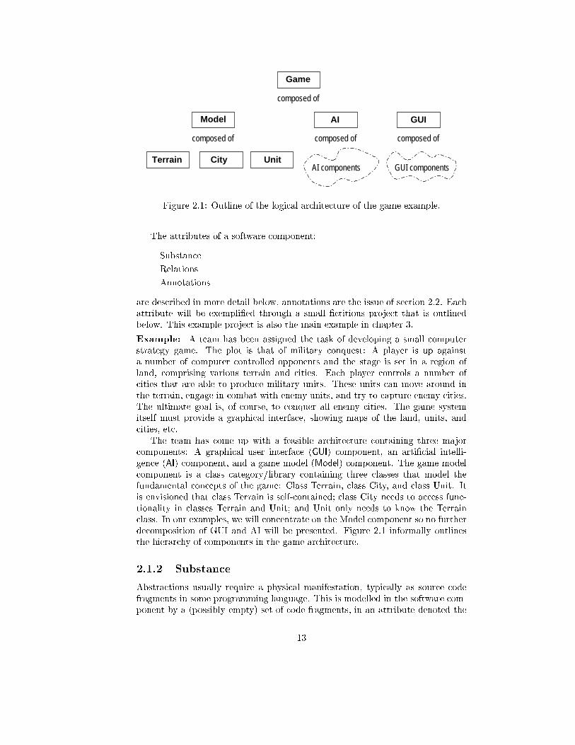
Figure 2.1: Outline of the logical architecture of the game example.
The attributes of a software component:
{ Substance
{ Relations
{ Annotations
are described in more detail below, annotations are the issue of section 2.2. Each
attribute will be exempli�ed through a small �ctitious project that is outlined
below. This example project is also the main example in chapter 3.
Example: A team has been assigned the task of developing a small computer
strategy game. The plot is that of military conquest: A player is up against
a number of computer controlled opponents and the stage is set in a region of
land, comprising various terrain and cities. Each player controls a number of
cities that are able to produce military units. These units can move around in
the terrain, engage in combat with enemy units, and try to capture enemy cities.
The ultimate goal is, of course, to conquer all enemy cities. The game system
itself must provide a graphical interface, showing maps of the land, units, and
cities, etc.
The team has come up with a feasible architecture containing three major
components: A graphical user interface (GUI) component, an arti�cial intelli-
gence (AI) component, and a game model (Model) component. The game model
component is a class category/library containing three classes that model the
fundamental concepts of the game: Class Terrain, class City, and class Unit. It
is envisioned that class Terrain is self-contained; class City needs to access func-
tionality in classes Terrain and Unit; and Unit only needs to know the Terrain
class. In our examples, we will concentrate on the Model component so no further
decomposition of GUI and AI will be presented. Figure 2.1 informally outlines
the hierarchy of components in the game architecture.
2.1.2 Substance
Abstractions usually require a physical manifestation, typically as source code
fragments in some programming language. This is modelled in the software com-
ponent by a (possibly empty) set of code fragments, in an attribute denoted the
13
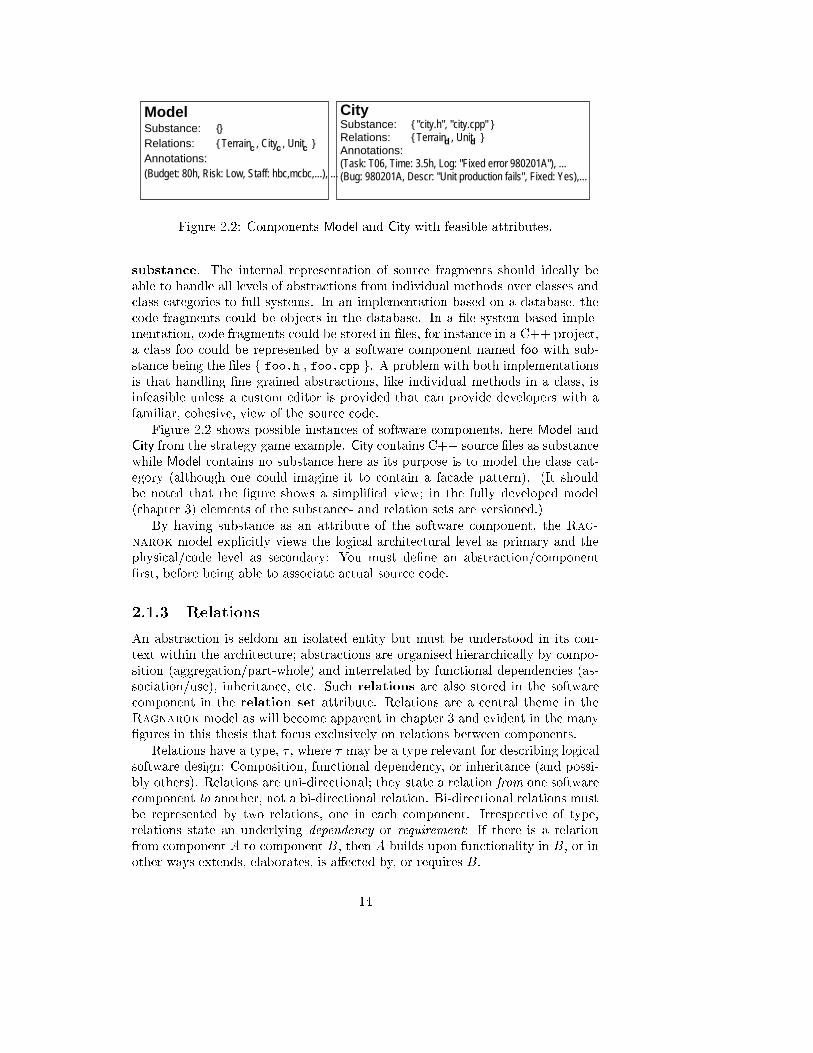
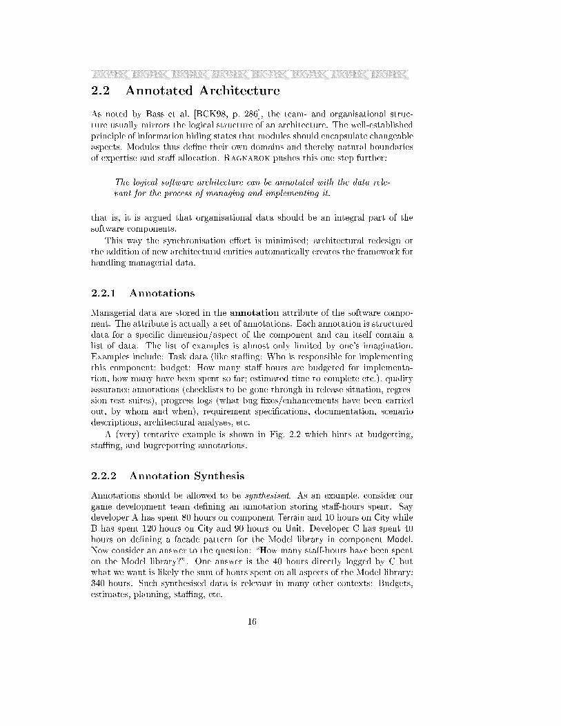
(Bug: 980201A, Descr: "Unit production fails", Fixed: Yes),...
Substance:City
{ "city.h", "city.cpp" }{ Terrain , Unit }Relations:
Annotations:(Task: T06, Time: 3.5h, Log: "Fixed error 980201A"), ...
d dSubstance:Model
{}{ Terrain , City , Unit }Relations:
Annotations:c c c
(Budget: 80h, Risk: Low, Staff: hbc,mcbc,...), ...
Figure 2.2: Components Model and City with feasible attributes.
substance. The internal representation of source fragments should ideally be
able to handle all levels of abstractions from individual methods over classes and
class-categories to full systems. In an implementation based on a database, the
code fragments could be objects in the database. In a �le-system based imple-
mentation, code fragments could be stored in �les, for instance in a C++ project,
a class foo could be represented by a software component named foo with sub-
stance being the �les f foo.h , foo.cpp g. A problem with both implementations
is that handling �ne grained abstractions, like individual methods in a class, is
infeasible unless a custom editor is provided that can provide developers with a
familiar, cohesive, view of the source code.
Figure 2.2 shows possible instances of software components, here Model and
City from the strategy game example. City contains C++ source �les as substance
while Model contains no substance here as its purpose is to model the class cat-
egory (although one could imagine it to contain a facade pattern). (It should
be noted that the �gure shows a simpli�ed view; in the fully developed model
(chapter 3) elements of the substance- and relation sets are versioned.)
By having substance as an attribute of the software component, the Rag-
narok model explicitly views the logical architectural level as primary and the
physical/code level as secondary: You must de�ne an abstraction/component
�rst, before being able to associate actual source code.
2.1.3 Relations
An abstraction is seldom an isolated entity but must be understood in its con-
text within the architecture; abstractions are organised hierarchically by compo-
sition (aggregation/part-whole) and interrelated by functional dependencies (as-
sociation/use), inheritance, etc. Such relations are also stored in the software
component in the relation set attribute. Relations are a central theme in the
Ragnarok model as will become apparent in chapter 3 and evident in the many
�gures in this thesis that focus exclusively on relations between components.
Relations have a type, � , where � may be a type relevant for describing logical
software design: Composition, functional dependency, or inheritance (and possi-
bly others). Relations are uni-directional; they state a relation from one software
component to another, not a bi-directional relation. Bi-directional relations must
be represented by two relations, one in each component. Irrespective of type,
relations state an underlying dependency or requirement: If there is a relation
from component A to component B, then A builds upon functionality in B, or in
other ways extends, elaborates, is a�ected by, or requires B.
14
Model
Terrain
City
Unit
GUI
Game
AI
GUI components
AI components
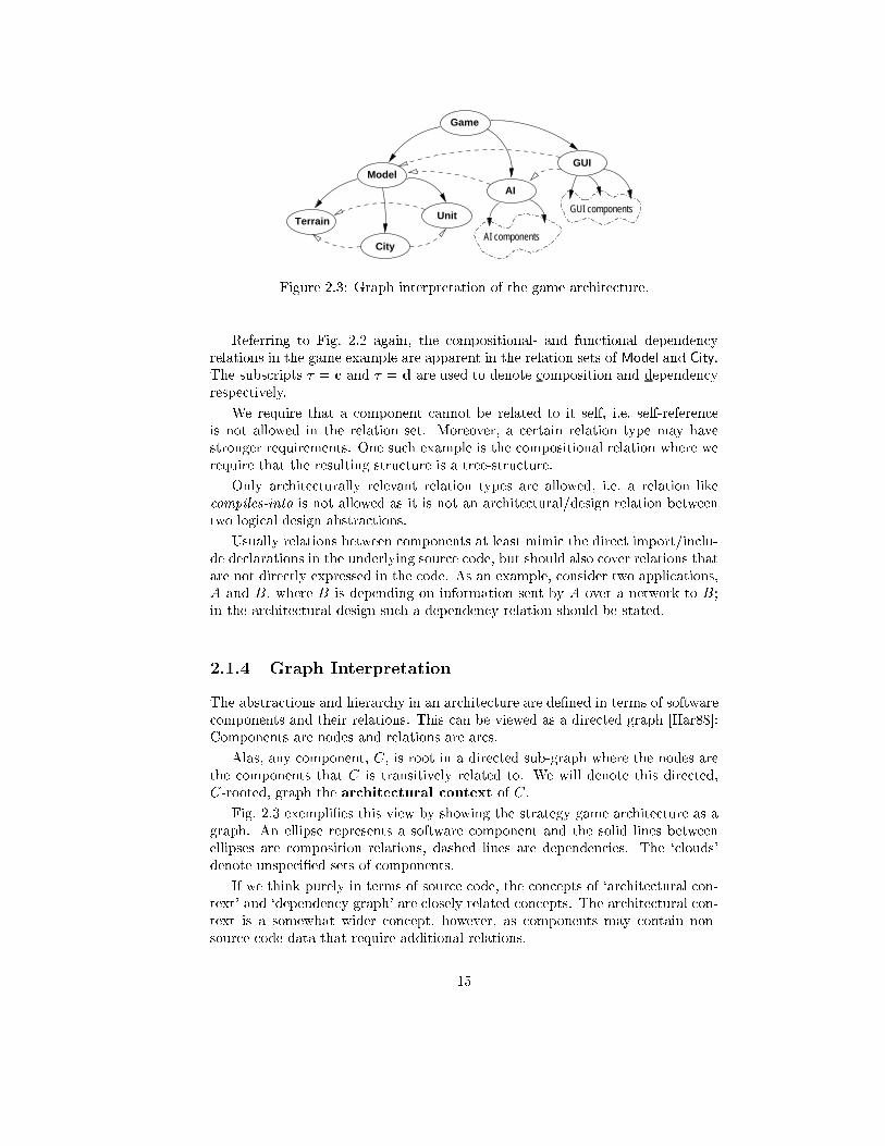
Figure 2.3: Graph interpretation of the game architecture.
Referring to Fig. 2.2 again, the compositional- and functional dependency
relations in the game example are apparent in the relation sets of Model and City.
The subscripts � = c and � = d are used to denote composition and dependency
respectively.
We require that a component cannot be related to it self, i.e. self-reference
is not allowed in the relation set. Moreover, a certain relation type may have
stronger requirements. One such example is the compositional relation where we
require that the resulting structure is a tree-structure.
Only architecturally relevant relation types are allowed, i.e. a relation like
compiles-into is not allowed as it is not an architectural/design relation between
two logical design abstractions.
Usually relations between components at least mimic the direct import/inclu-
de declarations in the underlying source code, but should also cover relations that
are not directly expressed in the code. As an example, consider two applications,
A and B, where B is depending on information sent by A over a network to B;
in the architectural design such a dependency relation should be stated.
2.1.4 Graph Interpretation
The abstractions and hierarchy in an architecture are de�ned in terms of software
components and their relations. This can be viewed as a directed graph [Har88]:
Components are nodes and relations are arcs.
Alas, any component, C, is root in a directed sub-graph where the nodes are
the components that C is transitively related to. We will denote this directed,
C-rooted, graph the architectural context of C.
Fig. 2.3 exempli�es this view by showing the strategy game architecture as a
graph. An ellipse represents a software component and the solid lines between
ellipses are composition relations, dashed lines are dependencies. The `clouds'
denote unspeci�ed sets of components.
If we think purely in terms of source code, the concepts of `architectural con-
text' and `dependency graph' are closely related concepts. The architectural con-
text is a somewhat wider concept, however, as components may contain non-
source code data that require additional relations.
15
2.2 Annotated Architecture
As noted by Bass et al. [BCK98, p. 286], the team- and organisational struc-
ture usually mirrors the logical structure of an architecture. The well-established
principle of information hiding states that modules should encapsulate changeable
aspects. Modules thus de�ne their own domains and thereby natural boundaries
of expertise and sta� allocation. Ragnarok pushes this one step further:
The logical software architecture can be annotated with the data rele-
vant for the process of managing and implementing it.
that is, it is argued that organisational data should be an integral part of the
software components.
This way the synchronisation e�ort is minimised; architectural redesign or
the addition of new architectural entities automatically creates the framework for
handling managerial data.
2.2.1 Annotations
Managerial data are stored in the annotation attribute of the software compo-
nent. The attribute is actually a set of annotations. Each annotation is structured
data for a speci�c dimension/aspect of the component and can itself contain a
list of data. The list of examples is almost only limited by one's imagination.
Examples include: Task data (like staÆng: Who is responsible for implementing
this component; budget: How many sta� hours are budgeted for implementa-
tion, how many have been spent so far; estimated-time-to-complete etc.), quality
assurance annotations (checklists to be gone through in release situation, regres-
sion test suites), progress logs (what bug-�xes/enhancements have been carried
out, by whom and when), requirement speci�cations, documentation, scenario
descriptions, architectural analyses, etc.
A (very) tentative example is shown in Fig. 2.2 which hints at budgetting,
staÆng, and bugreporting annotations.
2.2.2 Annotation Synthesis
Annotations should be allowed to be synthesised. As an example, consider our
game development team de�ning an annotation storing sta�-hours spent. Say
developer A has spent 80 hours on component Terrain and 10 hours on City while
B has spent 120 hours on City and 90 hours on Unit. Developer C has spent 40
hours on de�ning a facade pattern for the Model library in component Model.
Now consider an answer to the question: \How many sta�-hours have been spent
on the Model library?". One answer is the 40 hours directly logged by C but
what we want is likely the sum of hours spent on all aspects of the Model library:
340 hours. Such synthesised data is relevant in many other contexts: Budgets,
estimates, planning, staÆng, etc.
16
2.2.3 Status
Status and preliminary experiences with annotations on the architecture is re-
ported later in section 3.9.7.
2.3 Discussion
Though this chapter primarily sets the stage for the presentation in the following
chapters, some issues are relevant at this point.
2.3.1 The Orthogonality of Logical and Physical Structure
Abstractions usually have a physical implementation in a programming language.
The coupling between logical and physical structure vary greatly in di�erent
programming languages and environments: Integrated environments for Small-
talk [GR95] present the logical structure and hides the physical level; Java [AG98]
enforces a strict one-to-one mapping between (public) classes and �les, and be-
tween packages and directories; BETA [MMPN93] uses a special modularisation
language orthogonal to the programming language itself; and in C++ [Str97]
the coupling is purely based on conventions. Though they all o�er e.g. the class
abstraction, their storage models vary greatly.
Several authors claim that logical and physical structure are orthogonal, e.g.
Booch [Boo91, x 5.6] and Madsen et al. [MMPN93, x 17.1]. Nevertheless, the
question is whether this orthogonality is something to strive for. In practice,
developers often try hard to do the opposite, especially if deprived the privilege
of having a medium in which to describe the logical structure. Then �le-naming
and directory conventions become important tools to hint at the underlying logical
structure.
Also the distinction may be easy enough at the programming language near
level: A class is something di�erent than a �le. But what at more abstract levels?
After all, is the code generator a logical or physical part of a compiler? Or both?
Is a library a logical or physical entity? An application? Or a subsystem?
The position taken by Ragnarok is emphasis on the logical structure, and
letting physical structure be attributes of the former. And the view is that,
by using abstraction, we can group related entities into cohesive wholes. As an
example, the Model component in our game example, is viewed as a logical entity
that de�nes the underlying game model|even though the component perhaps
has no source code directly associated.
2.3.2 Derived Objects
In the current formulation, a software component does not handle derived ob-
jects, i.e. objects created by an automatic translation process performed on data
contained in the component. The typical example is the compiler, that translates
source code fragments into binary object code. It is envisioned that the soft-
ware component is extended with an attribute holding a pool of derived objects.
Each derived object should be classi�ed according to the rules/speci�cations that
17
have been used for the translation process, like for instance the switches given to
the compiler. This could form basis for an intelligent build management system
where the amount of recompilation could be minimised by avoiding unnecessary
recompilations. Such techniques were developed in the DSEE system [LJ87] and
continued in the later ClearCase product [Leb94].
2.3.3 Architectural Views
Kruchten advocates multiple views on architecture in the 4+1 view model [Kru95]
including the logical, process, physical, and development view.
At present, the focus in Ragnarok is on the static aspects of a software ar-
chitecture. This is not because other aspects, like dynamic, functional, process,
etc., are not interesting. But|\. . . once everything has been said, software is
de�ned by code" [Mey88, p. 30]. No matter what models we have in our minds,
in diagrams, or documented for any aspect, it is the static code that is reality.
The static aspect implicitly de�nes many of the others: The run-time dynamics,
functional characteristics, process properties, etc. The static structure is the one
developers perform their modi�cations and enhancements on, even to achieve a
goal in another aspect as e.g. improved speed, better load balancing, enhanced
security, etc. Not surprisingly, Rumbaugh et al. directly advocate the static struc-
ture as the more fundamental [RBP+91]. Architecture reconstruction tools, like
Dali [KC99], necessarily have to reconstruct from a software system's manifesta-
tion: The underlying source code.
In Krutchen terminology, the Ragnarok model is clearly based on the logical
view and regards the development view as attributes of the logical, through the
substance attribute of software components. One of the reasons that Kruchten
needs a separate development view is indeed release- and con�guration manage-
ment concerns, a problem we think the architectural software con�guration man-
agement model described in chapter 3 overcomes. Still, aspects like process- and
physical view as well as for instance the planning phase where one needs to view
tasks on a time scale, are not supported and cannot be handled nor visualised
well. We think, however, there are enough interesting and important aspects to
make the approach worthwhile.
18
Chapter 3
Architectural Software
Con�guration Management
In his seminal paper `Tools for Software Con�guration Management' [Tic88],
Tichy de�ned software con�guration management (SCM) as the process of `track-
ing the evolution of a software system'. Ovum describes con�guration manage-
ment in similar terms [IBW93, p. 17]: `Con�guration management is the ability
to identify, manage and control software as well as software-related components
[. . . ] as they change over time'. Basic operational aspects of SCM are highlighted
in the IEEE standard and reviewed by Dart [Dar91]:
{ Identi�cation: An identi�cation scheme re ects the structure of the project,
identi�es components and their types, making them unique and accessible
in some form.
{ Control: Controlling the release of a product and changes to it throughout
the life-cycle by having controls in place that ensure consistent software via
the creation of a baseline product.
{ Status Accounting: Recording and reporting the status of components and
change requests, and gathering vital statistics about components in the
product.
{ Audit and Review: Validating the completeness of a product and maintain-
ing consistency among the components by ensuring that the product is a
well-de�ned collection of components.
19
Evidently, the keywords are `control' and `evolution'. The importance of SCM in
modern software development is widely recognised as is apparent in the Capability
Maturity Model [PWCC97].
This chapter presents the architectural software con�guration manage-
ment model that forms the fundamental core of Ragnarok. It is important to
emphasis software con�guration management as a core discipline in the develop-
ment cycle and therefore use it as the fundamental technology in the software
development environment. Too often, development and programming environ-
ments do not provide SCM abilities; thus an additional SCM tool suite is required,
which potentially does not integrate well with the existing environment. Another
unfortunate consequence may be that SCM is not done at all.
Many aspects of the architectural software con�guration management model
have been presented in the papers [Chr97b, Chr98a, Chr99a]. On-line documen-
tation for the RCM prototype can be found in [Chr98e], technical documentation
in [Chr98d], and a guide of the tailorability aspects [Chr98c] from the Ragnarok
homepage http://daimi.au.dk/~hbc/Ragnarok.html.
This chapter starts with the underlying motivation and proposal of the ar-
chitectural software con�guration management model in section 3.1. Thereafter
the static and dynamic aspects of the basic model are introduced in section 3.2
and 3.3. Properties of the model are discussed in section 3.4 and the discussion is
extended to branching and merging architectures in section 3.5. The tailorability
aspect is described in 3.6. A short outline of design and implementation issues is
presented in section 3.7 followed by a brief description of the Ragnarok compan-
ion prototype, RCM, in section 3.8. Case studies from using the RCM prototype
as reported by external user groups are the topic of section 3.9. The model is dis-
cussed in section 3.10, related to similar work in section 3.11, and some pointers
to future work given in section 3.12.
3.1 Motivation and Proposal
The architectural software con�guration management model was primarily mo-
tivated out of concern for the software developers. In many projects, SCM has
meant bene�ts for the project managers but has been a burden for the developers
that have to supply the information required for the SCM system and tackle its
complexity [AM97]. The mantra is that `the software con�guration management
model should be natural for software developers'|in line with the overall vision
in Ragnarok.
The logical software architecture is the fundamental framework for designing
and implementing large scale software. Many traditional software con�guration
management tools nevertheless view `software' merely as a set of �les, not as
an architecture. Examples include CVS [Ber90] and commercial systems like
Microsoft SourceSafe [Mic97], ClearCase [Cle98], CCC/Harvest [CCC96], and
PVCS [PVC97] to mention a few. As J. Estublier notes: `They propose �le man-
agement where software management is needed.' [EC94, p. 100]. This introduces
an unfortunate impedance mismatch or mental gap between the concepts used in
the design domain (architectural level) and in the con�guration management do-
20
main (�le level). The tools does not support the concept of software architecture
directly, and the developers or maintainers have to correlate the two domains
mentally. Another key point is the fact that sets of �les can not provide unam-
biguous information about how the architecture itself evolves, for instance how
new classes are added or deleted and the dependency structure rearranged.
The hypothesis in Ragnarok is that to avoid these problems, we must view
a software system as an architecture, not as a set of �les, also in the software
con�guration management domain:
The logical software architecture is a natural framework for version-
and con�guration control.
Thereby, the impedance mismatch is lessened, making the model more natural for
developers. Another key issue, implicit in the hypothesis, and addressed by the
architectural model, is that architectural entities are seldom understood in isola-
tion: Abstractions are organised hierarchically by composition (aggregation/part-
whole), and interrelated by functional dependencies (association/use) and inher-
itance. For instance, to understand why feature X in class Y has mysteriously
stopped working though it worked perfectly last week, you often have to look for
the answer outside class Y itself|maybe in changed functionality in some classes
depended upon or an imported library. This illustrates that the architecture,
that forms the logical context for a given software entity, is just as important as
the entity itself. The Ragnarok architectural SCM model recognises this and
puts strong emphasis on traceability and reproducibility of con�gurations and
architectural changes, as described in the following sections.
3.2 Architectural Model, Static Aspects
In this section, the basic concepts of the architectural software con�guration man-
agement model will be presented. The model and its concepts will be presented
through formal descriptions and examples. The treatment is in uenced by papers
by Conradi and Westfechtel [CW97] and Lin and Reiss [LR97].
In chapter 2, we have been looking at the architecture of a software system
from the viewpoint of the developer. Discussing SCM issues, another viewpoint is
equally important, namely the viewpoint of the database where snapshots of the
software entities are stored. Conradi and Westfechtel [CW97, CW98] describe
a SCM system as a combination of product- and version space. The product
space contains software objects and their relationships, both of which evolve over
time, and is the space where development is carried out, thus representing a
developer-centred view. The version space stores states of the objects' evolution
and represents a database view. Often the two spaces are termed workspace and
repository.
This chapter deals primarily with software from the viewpoint of version space
(repository). The repository stores individual states of the evolution of compo-
nents, each state represented by a software component version.
The formal description of the model follows the tradition known from physics:
The emphasis is on a terse, unambiguous, and clear description, more than on
21
mathematical rigour|the intention is to present a model and discuss its proper-
ties in the context of software engineering. This implies that we draw heavily on
object-oriented and normal programming concept|for instance we treat a set as
a datatype where we can insert and delete elements, etc. Also, the emphasis is on
describing the properties that are special about this model and therefore cumber-
some descriptions of concepts that are well known in the domain are avoided|for
instance the description of the version graph is not comprehensive as the architec-
tural model assumes standard version graph properties, see e.g. [Tic88, CW97].
3.2.1 Basic Elements and Domains
In the presentation, we use �ve data types: Primitive data types are identities,
object references, and software entities, complex data types are sets and directed
graphs.
An identity is a property of an object, that distinguishes it from all other
objects [KC86].
Given an object A, a reference to A is denoted ref(A). Two references are
considered the same if they refer to the same object. We treat ref(A) as a �rst
class object though it resembles a function call. It is equal to the box operator,
A[] in BETA, and somewhat similar to A^ in Pascal, and *A or &A in C.
A software entity is a physical object, that de�nes a part of a software system.
In a �le based system a software entity is typically represented by a �le or part
of a �le; in a database it is a database object|however the only requirement of
the model, is that it is possible to test for equality of two software entities|the
sameness criteria of Conradi and Westfechtel [CW97].
Sets are described using standard mathematical notation. The same applies
to directed graphs. The usual notation [v; u] is used for a directed arc going from
node v to node u.
The standard `dot' notation is used to indicate individual �elds in a structured
object: C:CID denotes (the value of) the CID �eld of object C.
3.2.2 Software Component Version
A software component version represents a version of an abstraction:
22
Software
Component
Version
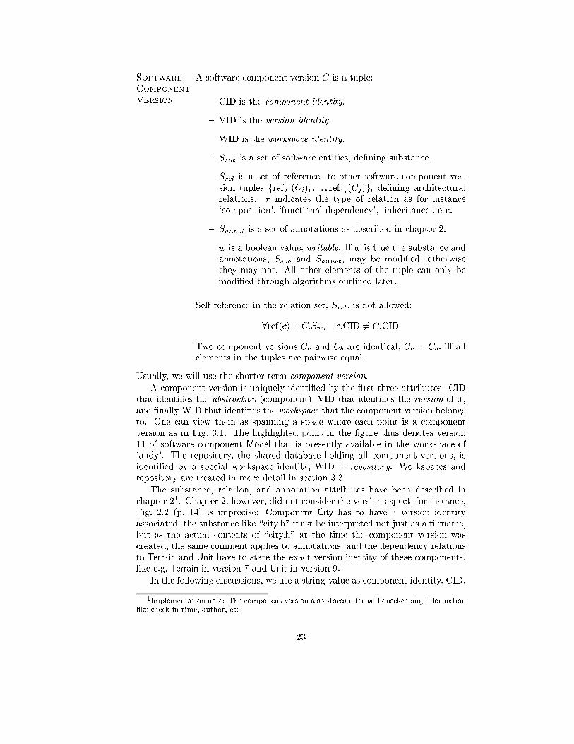
A software component version C is a tuple:
{ CID is the component identity.
{ VID is the version identity.
{ WID is the workspace identity.
{ Ssub is a set of software entities, de�ning substance.
{ Srel is a set of references to other software component ver-
sion tuples fref�i(Ci); : : : ; ref�j (Cj)g, de�ning architectural
relations. � indicates the type of relation as for instance
`composition', `functional dependency', `inheritance', etc.
{ Sannot is a set of annotations as described in chapter 2.
{ w is a boolean value, writable. If w is true the substance and
annotations, Ssub and Sannot, may be modi�ed, otherwise
they may not. All other elements of the tuple can only be
modi�ed through algorithms outlined later.
Self-reference in the relation set, Srel, is not allowed:
8ref(c) 2 C:Srel c:CID 6= C:CID
Two component versions Ca and Cb are identical, Ca = Cb, i� all
elements in the tuples are pairwise equal.
Usually, we will use the shorter term component version.
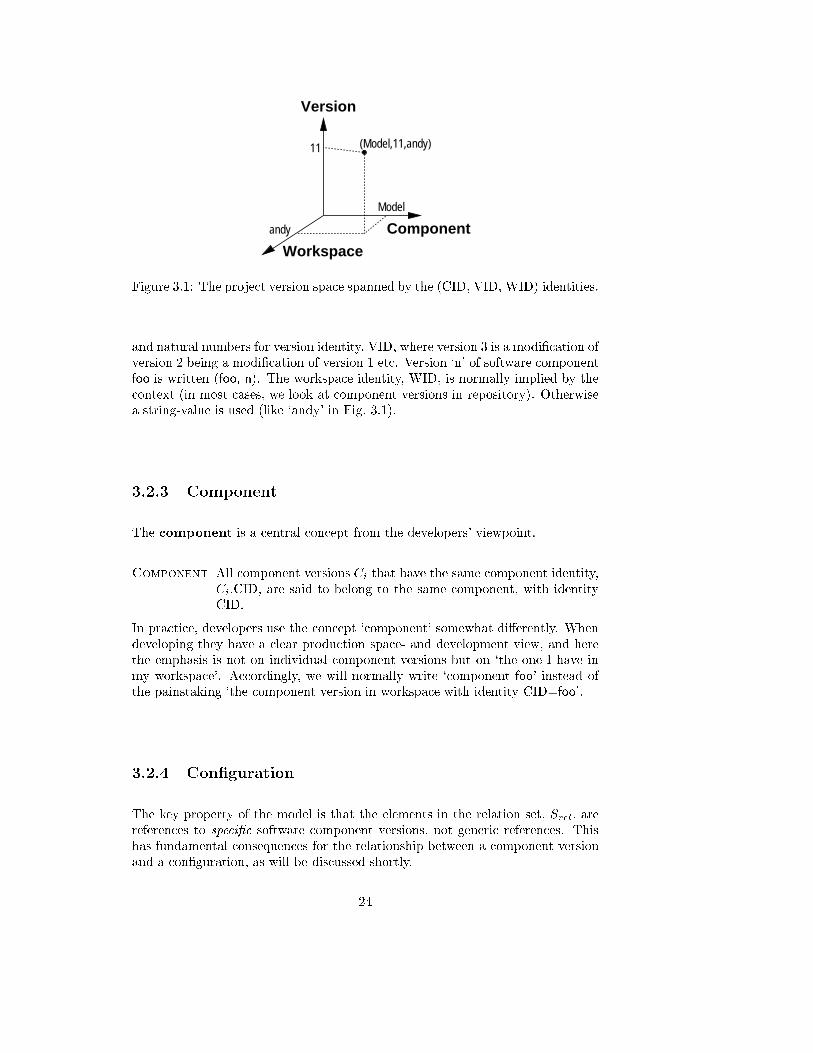
A component version is uniquely identi�ed by the �rst three attributes: CID
that identi�es the abstraction (component), VID that identi�es the version of it,
and �nally WID that identi�es the workspace that the component version belongs
to. One can view them as spanning a space where each point is a component
version as in Fig. 3.1. The highlighted point in the �gure thus denotes version
11 of software component Model that is presently available in the workspace of
`andy'. The repository, the shared database holding all component versions, is
identi�ed by a special workspace identity, WID = repository. Workspaces and
repository are treated in more detail in section 3.3.
The substance, relation, and annotation attributes have been described in
chapter 21. Chapter 2, however, did not consider the version aspect, for instance,
Fig. 2.2 (p. 14) is imprecise: Component City has to have a version identity
associated; the substance like \city.h" must be interpreted not just as a �lename,
but as the actual contents of \city.h" at the time the component version was
created; the same comment applies to annotations; and the dependency relations
to Terrain and Unit have to state the exact version identity of these components,
like e.g. Terrain in version 7 and Unit in version 9.
In the following discussions, we use a string-value as component identity, CID,
1Implementation note: The component version also stores internal housekeeping information
like check-in time, author, etc.
23
(Model,11,andy)
Version
Workspace
Component
Model
andy
11
Figure 3.1: The project version space spanned by the (CID, VID, WID) identities.
and natural numbers for version identity, VID, where version 3 is a modi�cation of
version 2 being a modi�cation of version 1 etc. Version `n' of software component
foo is written (foo, n). The workspace identity, WID, is normally implied by the
context (in most cases, we look at component versions in repository). Otherwise
a string-value is used (like `andy' in Fig. 3.1).
3.2.3 Component
The component is a central concept from the developers' viewpoint.
Component All component versions Ci that have the same component identity,
Ci.CID, are said to belong to the same component, with identity
CID.
In practice, developers use the concept `component' somewhat di�erently. When
developing they have a clear production space- and development view, and here
the emphasis is not on individual component versions but on `the one I have in
my workspace'. Accordingly, we will normally write `component foo' instead of
the painstaking `the component version in workspace with identity CID=foo'.
3.2.4 Con�guration
The key property of the model is that the elements in the relation set, Srel, are
references to speci�c software component versions, not generic references. This
has fundamental consequences for the relationship between a component version
and a con�guration, as will be discussed shortly.
24
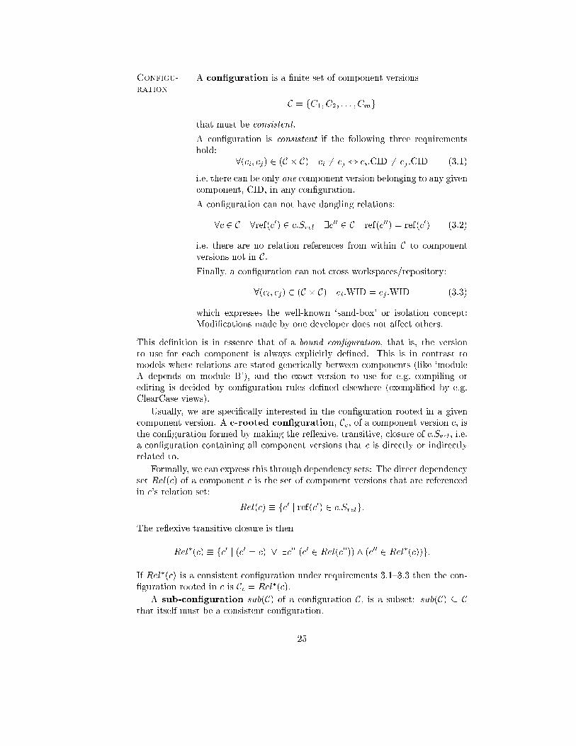
Configu-
ration
A con�guration is a �nite set of component versions
C = fC1; C2; : : : ; Cmg
that must be consistent.
A con�guration is consistent if the following three requirements
hold:
8(ci; cj) 2 (C � C) ci 6= cj , ci:CID 6= cj :CID (3.1)
i.e. there can be only one component version belonging to any given
component, CID, in any con�guration.
A con�guration can not have dangling relations:
8c 2 C 8ref(c0) 2 c:Srel 9c00 2 C ref(c00) = ref(c0) (3.2)
i.e. there are no relation references from within C to component
versions not in C.Finally, a con�guration can not cross workspaces/repository:
8(ci; cj) 2 (C � C) ci:WID = cj :WID (3.3)
which expresses the well-known `sand-box' or isolation concept:
Modi�cations made by one developer does not a�ect others.
This de�nition is in essence that of a bound con�guration, that is, the version
to use for each component is always explicitly de�ned. This is in contrast to
models where relations are stated generically between components (like `module
A depends on module B'), and the exact version to use for e.g. compiling or
editing is decided by con�guration rules de�ned elsewhere (exempli�ed by e.g.
ClearCase views).
Usually, we are speci�cally interested in the con�guration rooted in a given
component version. A c-rooted con�guration, Cc, of a component version c, isthe con�guration formed by making the re exive, transitive, closure of c:Srel, i.e.
a con�guration containing all component versions that c is directly or indirectly
related to.
Formally, we can express this through dependency sets: The direct dependency
set Rel(c) of a component c is the set of component versions that are referenced
in c's relation set:
Rel(c) � fc0 j ref(c0) 2 c:Srelg:
The re exive transitive closure is then
Rel�(c) � fc0 j (c0 = c) _ 9c00 (c0 2 Rel(c00)) ^ (c00 2 Rel
�(c))g:
If Rel�(c) is a consistent con�guration under requirements 3.1{3.3 then the con-
�guration rooted in c is Cc = Rel�(c).
A sub-con�guration sub(C) of a con�guration C, is a subset: sub(C) � Cthat itself must be a consistent con�guration.
25
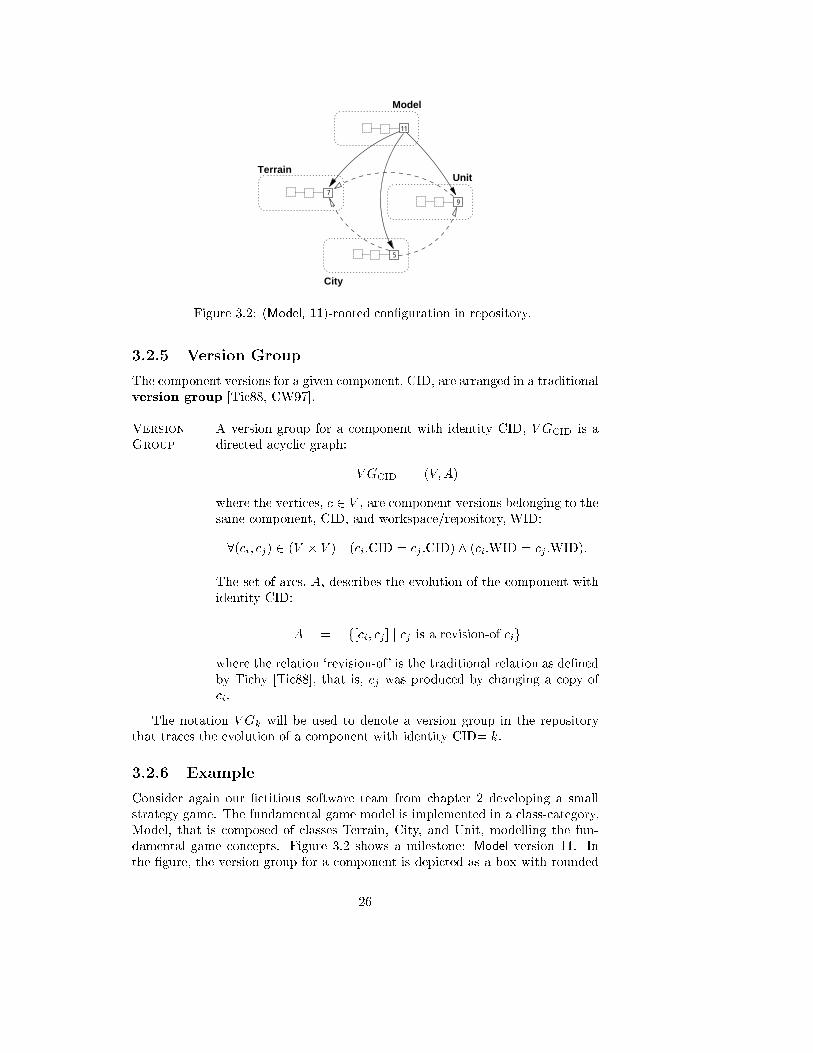
Model
Unit
11
5
97
Terrain
City
Figure 3.2: (Model, 11)-rooted con�guration in repository.
3.2.5 Version Group
The component versions for a given component, CID, are arranged in a traditional
version group [Tic88, CW97].
Version
Group
A version group for a component with identity CID, V GCID is a
directed acyclic graph:
V GCID = (V;A)
where the vertices, c 2 V , are component versions belonging to the
same component, CID, and workspace/repository, WID:
8(ci; cj) 2 (V � V ) (ci:CID = cj :CID) ^ (ci:WID = cj :WID):
The set of arcs, A, describes the evolution of the component with
identity CID:
A = f[ci; cj ] j cj is a revision-of cig
where the relation `revision-of' is the traditional relation as de�ned
by Tichy [Tic88], that is, cj was produced by changing a copy of
ci.
The notation V Gk will be used to denote a version group in the repository
that traces the evolution of a component with identity CID= k.
3.2.6 Example
Consider again our �ctitious software team from chapter 2 developing a small
strategy game. The fundamental game model is implemented in a class-category,
Model, that is composed of classes Terrain, City, and Unit, modelling the fun-
damental game concepts. Figure 3.2 shows a milestone: Model version 11. In
the �gure, the version group for a component is depicted as a box with rounded
26
corners containing the component versions (small quadrants with the version num-
bers inside) organised in a version graph. Solid lines going out of a component
version represent relations of type `composition', dashed lines `dependencies'. So,
Model version 11 is composed of (Terrain, 7), (City, 5), and (Unit, 9)|and (City, 5)
depends on (Unit, 9) and (Terrain, 7), and so on.
Thus the con�guration rooted in (Model, 11) is the set f(Model, 11), (Ter-
rain, 7), (City, 5), (Unit, 9)g and is a consistent con�guration under requirements
3.1{3.3.
If requirement 3.1 was not ensured, absurd situations could arise. For instance
in Fig. 3.2 if (City, 5) depended upon, say, (Unit, 8) then the con�guration ofModel
would refer to two di�erent versions of class Unit.
As is evident from Fig. 3.2, the component versions and their relationships
can be viewed as a directed graph: Component versions are nodes and relations
are arcs. Thus, a c-rooted con�guration can also be interpreted as the directed
(sub)graph, that is rooted in c.
3.3 Architectural Model, Dynamic Aspects
So far, static aspects of the model have been described. The dynamic aspect
is the check-in/check-out cycle that copies con�gurations from repository to a
workspace and vice versa.
3.3.1 Repository
The repository stores the individual states in the evolution of the components.
Repository A repository is a tuple
R = (ID; Svg)
where ID is the identity of the repository and Svg is a �nite set of
version groups:
Svg = fV G1; V G2; : : : ; V Gng:
with two requirements: All component versions in all version
groups are immutable and their workspace identity equals the
repository identity:
8vg 2 R:Svg 8c 2 vg:V (c:WID = R:ID) ^ (c:w = false) (3.4)
and for all component versions c, the c-rooted con�guration is con-
sistent
8vg 2 R:Svg 8c 2 vg:V the c-rooted con�guration is consistent:
(3.5)
27
3.3.2 Workspace
A workspace is a con�guration of component versions and a reference to the
repository that serves as the version database for these components.
Workspace A workspace is a tuple
W = (ID; C; ref(R))
where ID is the identity of the workspace and where we require
all component versions in con�guration C to belong to components
that have a version group in repository R:
8c 2 C 9vg 2 R:Svg 8c0 2 vg:V c0:CID = c:CID
and naturally that the component versions belong to this
workspace:
8c 2 C c:WID =W:ID:
The con�guration C represents the production space where component versionsare modi�ed, while R is the version space: A user can move component versions
between the two spaces through check-in and check-out operations described later.
Note that in this formulation a con�guration does not necessarily need to
contain versions of all components present in the repository. This opens up for
de�ning workspaces that only hold part of the components; in essence a sub-
con�guration2.
3.3.3 Project
In practice, it is convenient to consider components within the context of a pro-
ject. A project de�nes the domain in which development takes place.
Project A project is tuple
P = (R; SW )
where SW is a set of workspaces
SW = fW1;W2; : : : ;Wng
where the workspaces in SW of course must refer to the same repos-
itory
8Wi 2 SW Wi:ref(R) = P :ref(R)See also the discussion about project boundaries in section 3.12.5.
3.3.4 Revise
For the architecture to evolve, developers modify copies of component versions in
their workspaces, modifying substance, annotations, possibly stating new depen-
2Implementation note: This ability, however, is not available in the current Ragnarok
prototype.
28
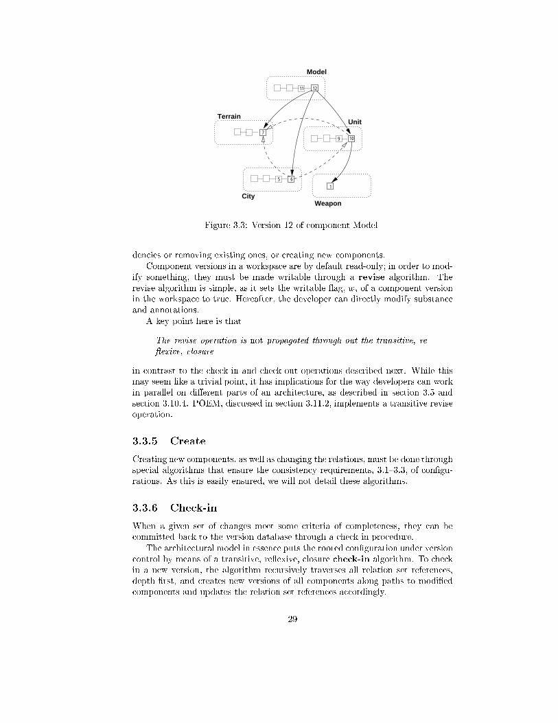
5 6
City1
Weapon
Model
Unit
11 12
79 10
Terrain
Figure 3.3: Version 12 of component Model
dencies or removing existing ones, or creating new components.
Component versions in a workspace are by default read-only; in order to mod-
ify something, they must be made writable through a revise algorithm. The
revise algorithm is simple, as it sets the writable ag, w, of a component version
in the workspace to true. Hereafter, the developer can directly modify substance
and annotations.
A key point here is that
The revise operation is not propagated through-out the transitive, re-
exive, closure
in contrast to the check-in and check-out operations described next. While this
may seem like a trivial point, it has implications for the way developers can work
in parallel on di�erent parts of an architecture, as described in section 3.5 and
section 3.10.4. POEM, discussed in section 3.11.2, implements a transitive revise
operation.
3.3.5 Create
Creating new components, as well as changing the relations, must be done through
special algorithms that ensure the consistency requirements, 3.1{3.3, of con�gu-
rations. As this is easily ensured, we will not detail these algorithms.
3.3.6 Check-in
When a given set of changes meet some criteria of completeness, they can be
committed back to the version database through a check-in procedure.
The architectural model in essence puts the rooted con�guration under version
control by means of a transitive, re exive, closure check-in algorithm. To check
in a new version, the algorithm recursively traverses all relation set references,
depth-�rst, and creates new versions of all components along paths to modi�ed
components and updates the relation set references accordingly.
29
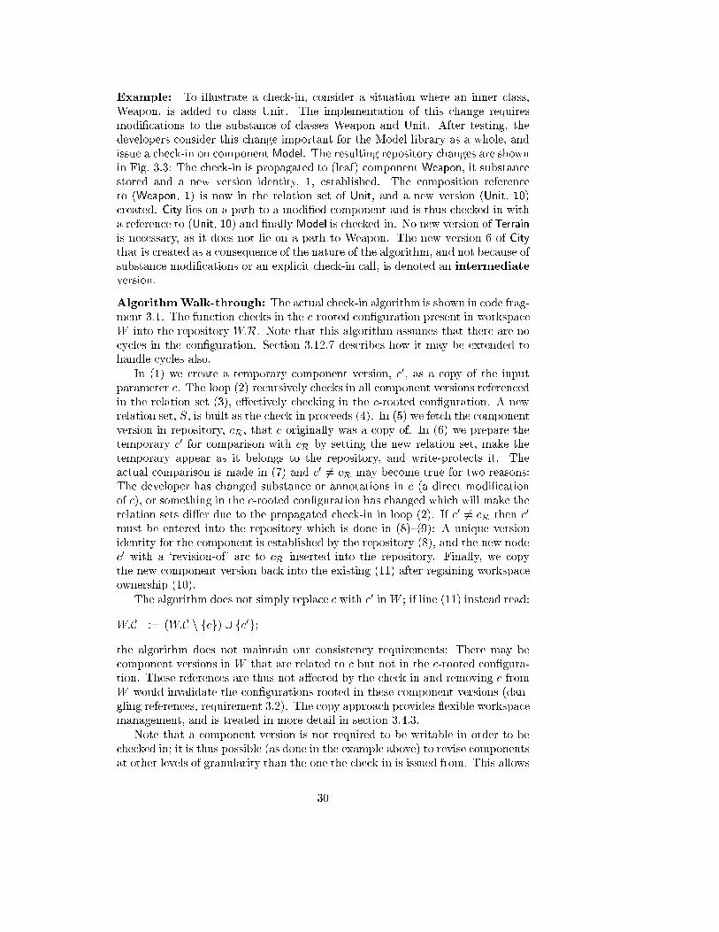
Example: To illustrate a check-in, consider a situation where an inner class,
Weapon, is added to class Unit. The implementation of this change requires
modi�cations to the substance of classes Weapon and Unit. After testing, the
developers consider this change important for the Model library as a whole, and
issue a check-in on component Model. The resulting repository changes are shown
in Fig. 3.3: The check-in is propagated to (leaf) component Weapon, it substance
stored and a new version identity, 1, established. The composition reference
to (Weapon, 1) is now in the relation set of Unit, and a new version (Unit, 10)
created. City lies on a path to a modi�ed component and is thus checked-in with
a reference to (Unit, 10) and �nally Model is checked-in. No new version of Terrain
is necessary, as it does not lie on a path to Weapon. The new version 6 of City
that is created as a consequence of the nature of the algorithm, and not because of
substance modi�cations or an explicit check-in call, is denoted an intermediate
version.
AlgorithmWalk-through: The actual check-in algorithm is shown in code frag-
ment 3.1. The function checks in the c-rooted con�guration present in workspace
W into the repository W:R. Note that this algorithm assumes that there are no
cycles in the con�guration. Section 3.12.7 describes how it may be extended to
handle cycles also.
In (1) we create a temporary component version, c0, as a copy of the input
parameter c. The loop (2) recursively checks in all component versions referenced
in the relation set (3), e�ectively checking in the c-rooted con�guration. A new
relation set, S, is built as the check-in proceeds (4). In (5) we fetch the component
version in repository, cR, that c originally was a copy of. In (6) we prepare the
temporary c0 for comparison with cR by setting the new relation set, make the
temporary appear as it belongs to the repository, and write-protects it. The
actual comparison is made in (7) and c0 6= cR may become true for two reasons:
The developer has changed substance or annotations in c (a direct modi�cation
of c), or something in the c-rooted con�guration has changed which will make the
relation sets di�er due to the propagated check-in in loop (2). If c0 6= cR then c0
must be entered into the repository which is done in (8){(9): A unique version
identity for the component is established by the repository (8), and the new node
c0 with a `revision-of' arc to cR inserted into the repository. Finally, we copy
the new component version back into the existing (11) after regaining workspace
ownership (10).
The algorithm does not simply replace c with c0 inW ; if line (11) instead read:
W:C := (W:C n fcg) [ fc0g;
the algorithm does not maintain our consistency requirements: There may be
component versions in W that are related to c but not in the c-rooted con�gura-
tion. These references are thus not a�ected by the check-in and removing c from
W would invalidate the con�gurations rooted in these component versions (dan-
gling references, requirement 3.2). The copy approach provides exible workspace
management, and is treated in more detail in section 3.4.3.
Note that a component version is not required to be writable in order to be
checked in; it is thus possible (as done in the example above) to revise components
at other levels of granularity than the one the check-in is issued from. This allows
30
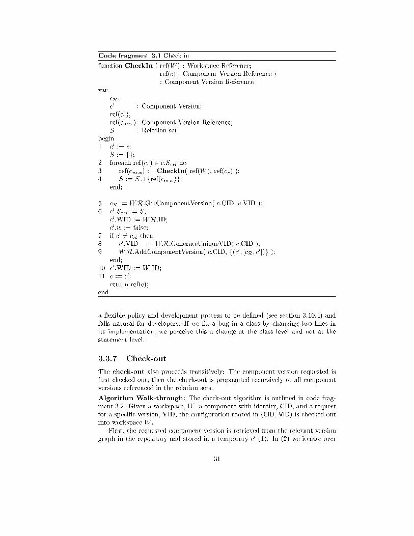
Code fragment 3.1 Check in
function CheckIn ( ref(W ) : Workspace Reference;
ref(c) : Component Version Reference )
: Component Version Reference
var
cR,
c0 : Component Version;
ref(cr),
ref(cnew) : Component Version Reference;
S : Relation set;
begin
1 c0 := c;
S := fg;2 foreach ref(cr) 2 c:Srel do
3 ref(cnew) := CheckIn( ref(W ), ref(cr) );
4 S := S [ fref(cnew)g;end;
5 cR := W:R.GetComponentVersion( c.CID, c.VID );
6 c0:Srel := S;
c0:WID := W:R:ID;
c0:w := false;
7 if c0 6= cR then
8 c0.VID := W:R.GenerateUniqueVID( c.CID );
9 W:R.AddComponentVersion( c.CID, f(c0; [cR; c0])g );end;
10 c0.WID := W .ID;
11 c := c0;
return ref(c);
end
a exible policy and development process to be de�ned (see section 3.10.4) and
falls natural for developers: If we �x a bug in a class by changing two lines in
its implementation, we perceive this a change at the class level and not at the
statement level.
3.3.7 Check-out
The check-out also proceeds transitively: The component version requested is
�rst checked out, then the check-out is propagated recursively to all component
versions referenced in the relation sets.
Algorithm Walk-through: The check-out algorithm is outlined in code frag-
ment 3.2. Given a workspace, W , a component with identity, CID, and a request
for a speci�c version, VID, the con�guration rooted in (CID, VID) is checked out
into workspace W .
First, the requested component version is retrieved from the relevant version
graph in the repository and stored in a temporary c0 (1). In (2) we iterate over
31
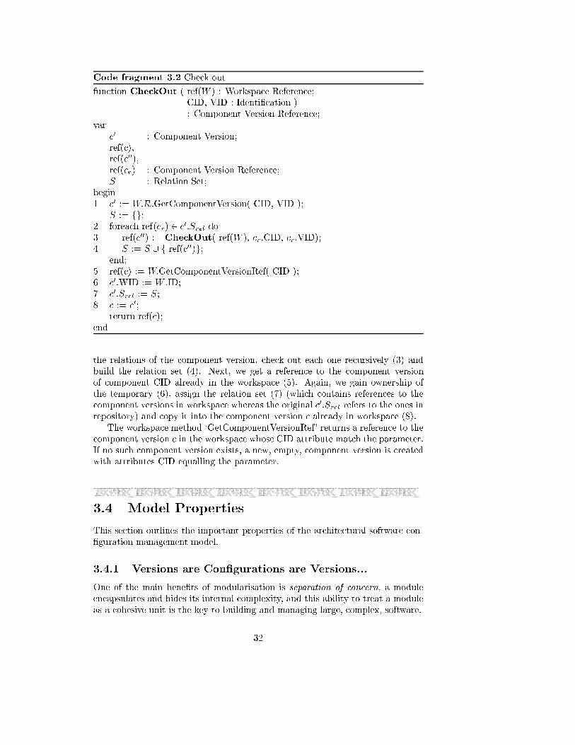
Code fragment 3.2 Check out
function CheckOut ( ref(W ) : Workspace Reference;
CID, VID : Identi�cation )
: Component Version Reference;
var
c0 : Component Version;
ref(c),
ref(c00),
ref(cr) : Component Version Reference;
S : Relation Set;
begin
1 c0 := W:R.GetComponentVersion( CID, VID );
S := fg;2 foreach ref(cr) 2 c
0:Srel do
3 ref(c00) := CheckOut( ref(W ), cr.CID, cr.VID);
4 S := S [ f ref(c00)g;end;
5 ref(c) := W:GetComponentVersionRef( CID );
6 c0.WID := W .ID;
7 c0:Srel := S;
8 c := c0;
return ref(c);
end
the relations of the component version, check out each one recursively (3) and
build the relation set (4). Next, we get a reference to the component version
of component CID already in the workspace (5). Again, we gain ownership of
the temporary (6), assign the relation set (7) (which contains references to the
component versions in workspace whereas the original c0:Srel refers to the ones in
repository) and copy it into the component version c already in workspace (8).
The workspace method `GetComponentVersionRef' returns a reference to the
component version c in the workspace whose CID attribute match the parameter.
If no such component version exists, a new, empty, component version is created
with attributes CID equalling the parameter.
3.4 Model Properties
This section outlines the important properties of the architectural software con-
�guration management model.
3.4.1 Versions are Con�gurations are Versions...
One of the main bene�ts of modularisation is separation of concern, a module
encapsulates and hides its internal complexity, and this ability to treat a module
as a cohesive unit is the key to building and managing large, complex, software.
32
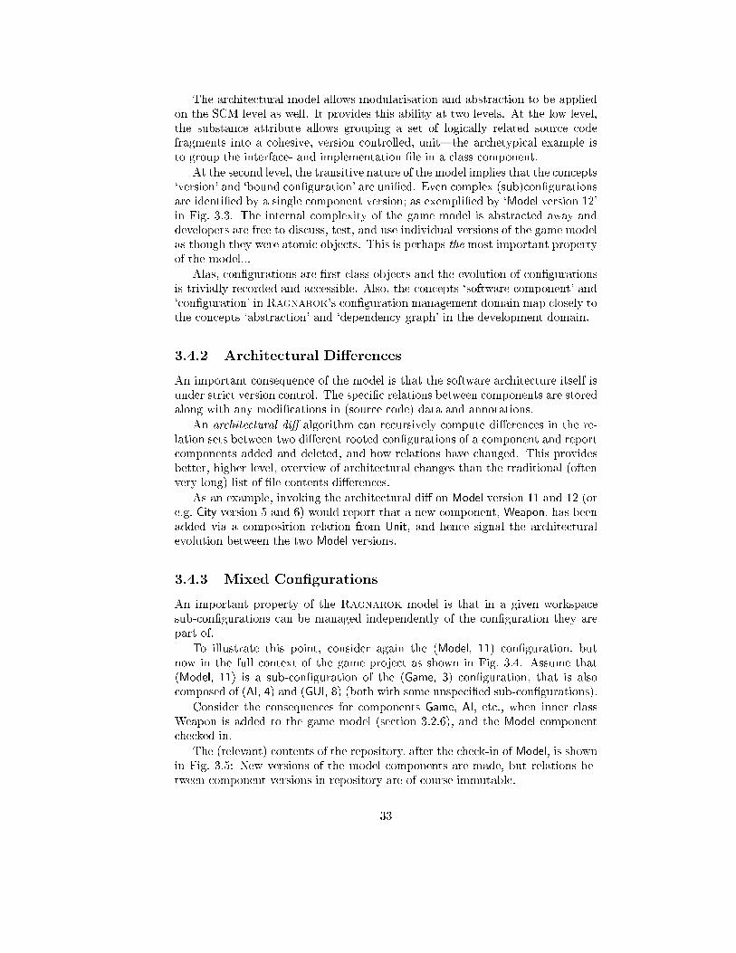
The architectural model allows modularisation and abstraction to be applied
on the SCM level as well. It provides this ability at two levels. At the low level,
the substance attribute allows grouping a set of logically related source code
fragments into a cohesive, version controlled, unit|the archetypical example is
to group the interface- and implementation �le in a class component.
At the second level, the transitive nature of the model implies that the concepts
`version' and `bound con�guration' are uni�ed. Even complex (sub)con�gurations
are identi�ed by a single component version; as exempli�ed by `Model version 12'
in Fig. 3.3. The internal complexity of the game model is abstracted away and
developers are free to discuss, test, and use individual versions of the game model
as though they were atomic objects. This is perhaps the most important property
of the model...
Alas, con�gurations are �rst class objects and the evolution of con�gurations
is trivially recorded and accessible. Also, the concepts `software component' and
`con�guration' in Ragnarok's con�guration management domain map closely to
the concepts `abstraction' and `dependency graph' in the development domain.
3.4.2 Architectural Di�erences
An important consequence of the model is that the software architecture itself is
under strict version control. The speci�c relations between components are stored
along with any modi�cations in (source code) data and annotations.
An architectural di� algorithm can recursively compute di�erences in the re-
lation sets between two di�erent rooted con�gurations of a component and report
components added and deleted, and how relations have changed. This provides
better, higher level, overview of architectural changes than the traditional (often
very long) list of �le contents di�erences.
As an example, invoking the architectural di� on Model version 11 and 12 (or
e.g. City version 5 and 6) would report that a new component, Weapon, has been
added via a composition relation from Unit, and hence signal the architectural
evolution between the two Model versions.
3.4.3 Mixed Con�gurations
An important property of the Ragnarok model is that in a given workspace
sub-con�gurations can be managed independently of the con�guration they are
part of.
To illustrate this point, consider again the (Model, 11) con�guration, but
now in the full context of the game project as shown in Fig. 3.4. Assume that
(Model, 11) is a sub-con�guration of the (Game, 3) con�guration, that is also
composed of (AI, 4) and (GUI, 8) (both with some unspeci�ed sub-con�gurations).
Consider the consequences for components Game, AI, etc., when inner class
Weapon is added to the game model (section 3.2.6), and the Model component
checked in.
The (relevant) contents of the repository, after the check-in of Model, is shown
in Fig. 3.5: New versions of the model components are made, but relations be-
tween component versions in repository are of course immutable.
33
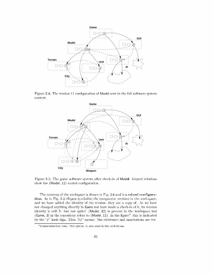
Game
3
City
5
4
8
AI
Unit
11
97
Terrain
Model
GUI
Figure 3.4: The version 11 con�guration of Model seen in the full software system
context.
Game
3
5 6
City1
Weapon
4
8
AI
Unit
11 12
79 10
Terrain
Model
GUI
Figure 3.5: The game software system after check-in of Model. Grayed relations
show the (Model, 11)-rooted con�guration.
The contents of the workspace is shown in Fig. 3.6 and is amixed con�gura-
tion. As in Fig. 2.3 ellipses symbolise the component versions in the workspace,
and we have added the identity of the version, they are a copy of. As we have
not changed anything directly in Game nor have made a check-in of it, its version
identity is still 3|but not quite! (Model, 12) is present in the workspace but
(Game, 3) in the repository refers to (Model, 11). In the �gure3, this is indicated
by the `#' hash sign. Thus `3#' means: `the substance and annotations are ver-
3Implementation note: This symbol is also used in the prototypes.
34
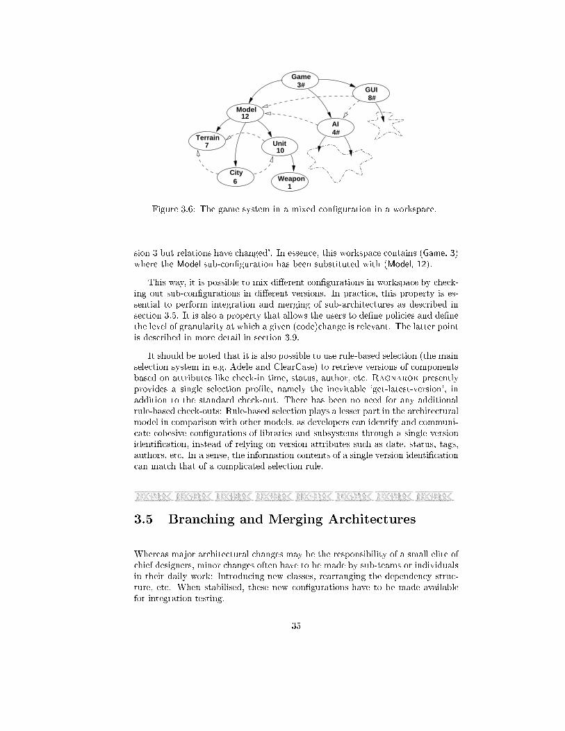
Terrain
Model
Unit
City
3#
8#
Weapon
4#AI
GUI
Game
12
710
61
Figure 3.6: The game system in a mixed con�guration in a workspace.
sion 3 but relations have changed'. In essence, this workspace contains (Game, 3)
where the Model sub-con�guration has been substituted with (Model, 12).
This way, it is possible to mix di�erent con�gurations in workspace by check-
ing out sub-con�gurations in di�erent versions. In practice, this property is es-
sential to perform integration and merging of sub-architectures as described in
section 3.5. It is also a property that allows the users to de�ne policies and de�ne
the level of granularity at which a given (code)change is relevant. The latter point
is described in more detail in section 3.9.
It should be noted that it is also possible to use rule-based selection (the main
selection system in e.g. Adele and ClearCase) to retrieve versions of components
based on attributes like check-in time, status, author, etc. Ragnarok presently
provides a single selection pro�le, namely the inevitable `get-latest-version', in
addition to the standard check-out. There has been no need for any additional
rule-based check-outs: Rule-based selection plays a lesser part in the architectural
model in comparison with other models, as developers can identify and communi-
cate cohesive con�gurations of libraries and subsystems through a single version
identi�cation, instead of relying on version attributes such as date, status, tags,
authors, etc. In a sense, the information contents of a single version identi�cation
can match that of a complicated selection rule.
3.5 Branching and Merging Architectures
Whereas major architectural changes may be the responsibility of a small elite of
chief designers, minor changes often have to be made by sub-teams or individuals
in their daily work: Introducing new classes, rearranging the dependency struc-
ture, etc. When stabilised, these new con�gurations have to be made available
for integration testing.
35
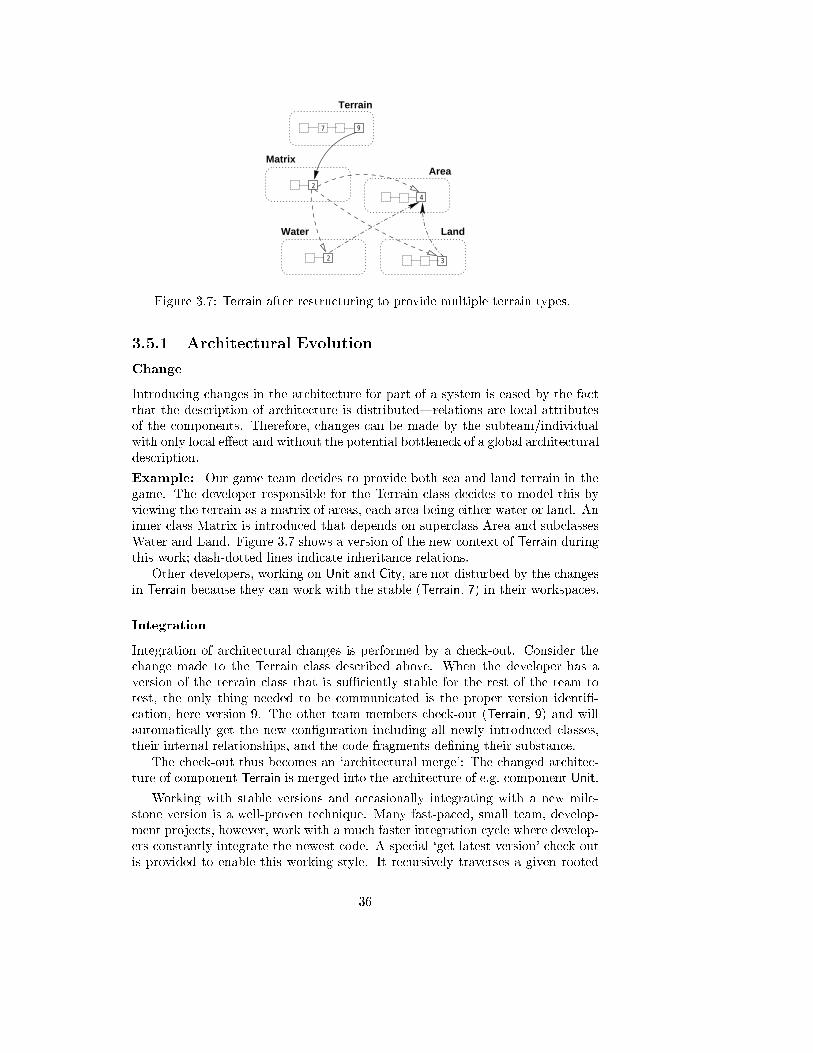
2
Matrix
4
Area
2
Water
3
Land
Terrain
7 9
Figure 3.7: Terrain after restructuring to provide multiple terrain types.
3.5.1 Architectural Evolution
Change
Introducing changes in the architecture for part of a system is eased by the fact
that the description of architecture is distributed|relations are local attributes
of the components. Therefore, changes can be made by the subteam/individual
with only local e�ect and without the potential bottleneck of a global architectural
description.
Example: Our game team decides to provide both sea and land terrain in the
game. The developer responsible for the Terrain class decides to model this by
viewing the terrain as a matrix of areas, each area being either water or land. An
inner class Matrix is introduced that depends on superclass Area and subclasses
Water and Land. Figure 3.7 shows a version of the new context of Terrain during
this work; dash-dotted lines indicate inheritance relations.
Other developers, working on Unit and City, are not disturbed by the changes
in Terrain because they can work with the stable (Terrain, 7) in their workspaces.
Integration
Integration of architectural changes is performed by a check-out. Consider the
change made to the Terrain class described above. When the developer has a
version of the terrain class that is suÆciently stable for the rest of the team to
test, the only thing needed to be communicated is the proper version identi�-
cation, here version 9. The other team members check-out (Terrain, 9) and will
automatically get the new con�guration including all newly introduced classes,
their internal relationships, and the code fragments de�ning their substance.
The check-out thus becomes an `architectural merge': The changed architec-
ture of component Terrain is merged into the architecture of e.g. component Unit.
Working with stable versions and occasionally integrating with a new mile-
stone version is a well-proven technique. Many fast-paced, small team, develop-
ment projects, however, work with a much faster integration cycle where develop-
ers constantly integrate the newest code. A special `get-latest-version' check-out
is provided to enable this working style. It recursively traverses a given rooted
36
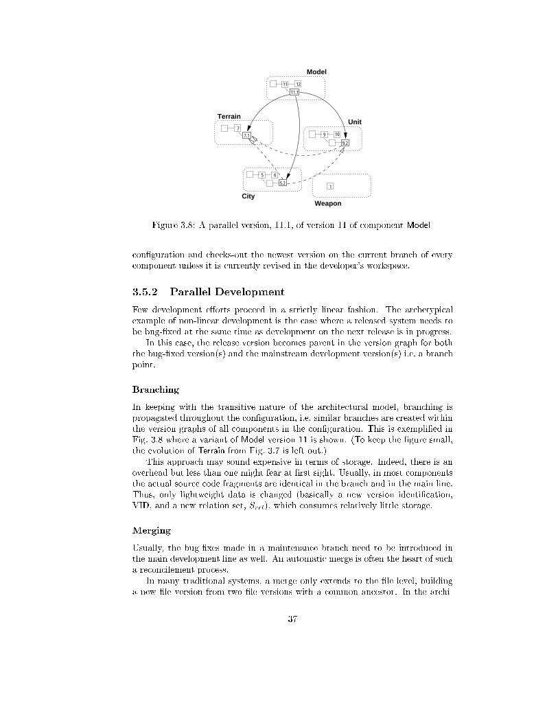
1
11 12
5 6
9 10
Model
UnitTerrain
CityWeapon
7
7.1
5.2
9.2
11.1
Figure 3.8: A parallel version, 11.1, of version 11 of component Model
con�guration and checks-out the newest version on the current branch of every
component unless it is currently revised in the developer's workspace.
3.5.2 Parallel Development
Few development e�orts proceed in a strictly linear fashion. The archetypical
example of non-linear development is the case where a released system needs to
be bug-�xed at the same time as development on the next release is in progress.
In this case, the release version becomes parent in the version graph for both
the bug-�xed version(s) and the mainstream development version(s) i.e. a branch
point.
Branching
In keeping with the transitive nature of the architectural model, branching is
propagated throughout the con�guration, i.e. similar branches are created within
the version graphs of all components in the con�guration. This is exempli�ed in
Fig. 3.8 where a variant of Model version 11 is shown. (To keep the �gure small,
the evolution of Terrain from Fig. 3.7 is left out.)
This approach may sound expensive in terms of storage. Indeed, there is an
overhead but less than one might fear at �rst sight. Usually, in most components
the actual source code fragments are identical in the branch and in the main line.
Thus, only lightweight data is changed (basically a new version identi�cation,
VID, and a new relation set, Srel), which consumes relatively little storage.
Merging
Usually, the bug-�xes made in a maintenance branch need to be introduced in
the main development line as well. An automatic merge is often the heart of such
a reconcilement process.
In many traditional systems, a merge only extends to the �le level, building
a new �le version from two �le versions with a common ancestor. In the archi-
37
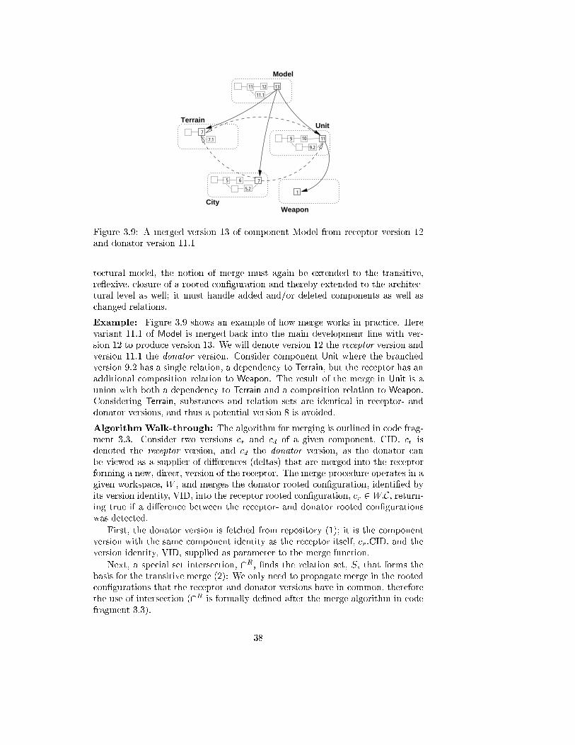
11 12
5 6
9 10
Model
UnitTerrain
CityWeapon
7
7.1
5.2
9.2
11.1
1
13
11
7
Figure 3.9: A merged version 13 of component Model from receptor version 12
and donator version 11.1
tectural model, the notion of merge must again be extended to the transitive,
re exive, closure of a rooted con�guration and thereby extended to the architec-
tural level as well; it must handle added and/or deleted components as well as
changed relations.
Example: Figure 3.9 shows an example of how merge works in practice. Here
variant 11.1 of Model is merged back into the main development line with ver-
sion 12 to produce version 13. We will denote version 12 the receptor version and
version 11.1 the donator version. Consider component Unit where the branched
version 9.2 has a single relation, a dependency to Terrain, but the receptor has an
additional composition relation to Weapon. The result of the merge in Unit is a
union with both a dependency to Terrain and a composition relation to Weapon.
Considering Terrain, substances and relation sets are identical in receptor- and
donator versions, and thus a potential version 8 is avoided.
Algorithm Walk-through: The algorithm for merging is outlined in code frag-
ment 3.3. Consider two versions cr and cd of a given component, CID. cr is
denoted the receptor version, and cd the donator version, as the donator can
be viewed as a supplier of di�erences (deltas) that are merged into the receptor
forming a new, direct, version of the receptor. The merge procedure operates in a
given workspace, W , and merges the donator rooted con�guration, identi�ed by
its version identity, VID, into the receptor rooted con�guration, cr 2W:C, return-ing true if a di�erence between the receptor- and donator rooted con�gurations
was detected.
First, the donator version is fetched from repository (1); it is the component
version with the same component identity as the receptor itself, cr:CID, and the
version identity, VID, supplied as parameter to the merge function.
Next, a special set intersection, \R, �nds the relation set, S, that forms the
basis for the transitive merge (2): We only need to propagate merge in the rooted
con�gurations that the receptor and donator versions have in common, therefore
the use of intersection (\R is formally de�ned after the merge algorithm in code
fragment 3.3).
38
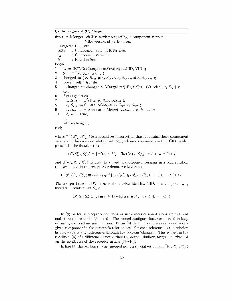
Code fragment 3.3 Merge
function Merge( ref(W ): workspace; ref(cr) : component version;
VID: version id ) : Boolean;
changed : Boolean;
ref(c) : Component Version Reference;
cd : Component Version;
S : Relation Set;
begin
1 cd := W:R.GetComponentVersion( cr.CID, VID );
2 S := \R(cr:Srel; cd:Srel );3 changed := ( cr:Ssub 6= cd:Ssub _ cr:Sannot 6= cd:Sannot );
4 foreach ref(c) 2 S do
5 changed := changed _ Merge( ref(W ), ref(c), DV( ref(c), cd:Srel) );
end;
6 if changed then
7 cr:Srel := [C(W:C; cr:Srel; cd:Srel );8 cr:Ssub := SubstanceMerge( cr:Ssub; cd:Ssub );
9 cr:Sannot := AnnotationMerge( cr:Sannot; cd:Sannot );
10 cr:w := true;
end;
return changed;
end;
where \R( Srrel; S
d
rel) is a special set intersection that maintains those component
versions in the receptor relation set, Srrel, whose component identity, CID, is also
present in the donator set:
\R(Srrel; S
d
rel) � fref(c) 2 S
r
relj 9ref(c0) 2 S
d
relc:CID = c
0:CIDg
and [C(C; Srrel; S
d
rel) de�nes the subset of component versions in a con�guration
that are listed in the receptor or donator relation set:
[C(C; Srrel; S
d
rel) � fref(c) 2 C j 9ref(c0) 2 (Sr
rel[ Sd
rel) c:CID = c
0:CIDg:
The integer function DV returns the version identity, VID, of a component, c,
listed in a relation set Srel:
DV(ref(c); Srel) � c0:VID where c0 2 Srel ^ c0:CID = c:CID
In (3) we test if receptor- and donator substances or annotations are di�erent
and store the result in `changed'. The rooted con�gurations are merged in loop
(4) using a special integer function, DV, in (5) that �nds the version identity of a
given component in the donator's relation set. For each reference in the relation
list, S, we note any di�erences through the boolean `changed'. This is used in the
condition (6); if a di�erence is noted then the actual, shallow, merge is performed
on the attributes of the receptor in line (7){(10).
In line (7) the relation sets are merged using a special set union [C(C; Srrel; S
d
rel)
39
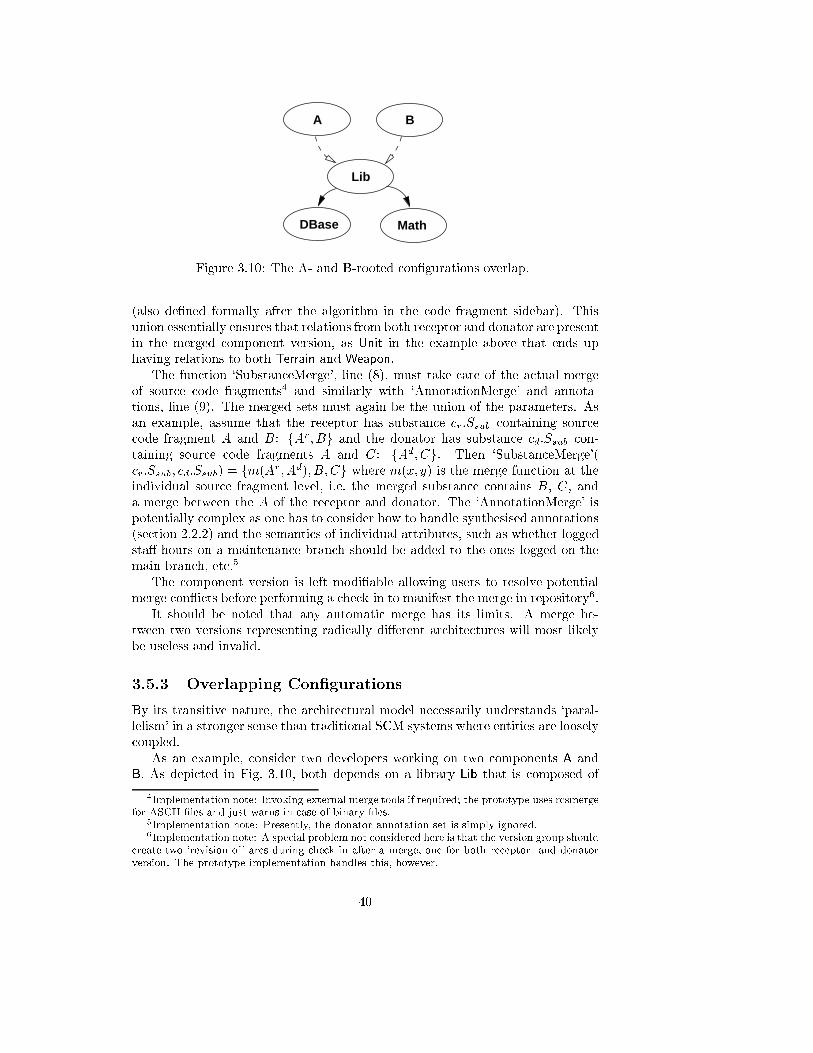
A B
Lib
MathDBase
Figure 3.10: The A- and B-rooted con�gurations overlap.
(also de�ned formally after the algorithm in the code fragment sidebar). This
union essentially ensures that relations from both receptor and donator are present
in the merged component version, as Unit in the example above that ends up
having relations to both Terrain and Weapon.
The function `SubstanceMerge', line (8), must take care of the actual merge
of source code fragments4 and similarly with `AnnotationMerge' and annota-
tions, line (9). The merged sets must again be the union of the parameters. As
an example, assume that the receptor has substance cr:Ssub containing source
code fragment A and B: fAr; Bg and the donator has substance cd:Ssub con-
taining source code fragments A and C: fAd; Cg. Then `SubstanceMerge'(
cr:Ssub; cd:Ssub) = fm(Ar; A
d); B; Cg where m(x; y) is the merge function at the
individual source fragment level, i.e. the merged substance contains B, C, and
a merge between the A of the receptor and donator. The `AnnotationMerge' is
potentially complex as one has to consider how to handle synthesised annotations
(section 2.2.2) and the semantics of individual attributes, such as whether logged
sta�-hours on a maintenance branch should be added to the ones logged on the
main branch, etc.5
The component version is left modi�able allowing users to resolve potential
merge con icts before performing a check-in to manifest the merge in repository6.
It should be noted that any automatic merge has its limits. A merge be-
tween two versions representing radically di�erent architectures will most likely
be useless and invalid.
3.5.3 Overlapping Con�gurations
By its transitive nature, the architectural model necessarily understands `paral-
lelism' in a stronger sense than traditional SCM systems where entities are loosely
coupled.
As an example, consider two developers working on two components A and
B. As depicted in Fig. 3.10, both depends on a library Lib that is composed of
4Implementation note: Invoking external merge tools if required; the prototype uses rcsmerge
for ASCII �les and just warns in case of binary �les.5Implementation note: Presently, the donator annotation set is simply ignored.6Implementation note: A special problem not considered here is that the version group should
create two `revision-of' arcs during check-in after a merge, one for both receptor- and donator
version. The prototype implementation handles this, however.
40
modules DBase and Math. This architecture becomes tricky in a situation where,
say, the A developer must modify DBase at the same time as the B developer
must change Math, and they decide to perform the check-in from components A
and B respectively. As Lib occurs in the path of both check-in operations, one
of the check-ins will necessarily result in a branched version of Lib if no action is
taken to avoid it. The situation could lead to a race-condition.
Seen from a classical SCM perspective this situation may seem odd: At some
time we have to `merge' the library even though the two developers have modi�ed
disjoint sets of code fragments. But the fact is that the two developers have worked
in parallel at the library level of granularity|and the architectural model re ects
this fact.
The situation is avoided simply by observing standard software engineering
doctrine [Som92]: Do bottom-up integration testing. The developers should verify
their DBase and Math changes in isolation, then do the integration testing on Lib
and �nally create a new library version that can serve as basis for the continued
work on components A and B. If there are many, closely related, changes necessary
in both A/B and the library subcomponents, the special check-out that always
retrieves the newest code (section 3.5.1) is useful.
Alternatively, they may branch the library component (automatically creat-
ing branches for DBase and Math) and work in isolation on separate branches,
postponing the merge.
3.6 Tailorability
No two software development projects are the same and consequently require-
ments on the SCM system will vary. Ragnarok supports a limited form of tai-
lorability to meet the needs of the individual project through a build-in scripting
language: Tcl [Ous94].
Presently, the scripting language is used for two purposes in the implementa-
tion of the architectural software con�guration management model: As customis-
able report generator and for operational triggers.
The Tcl language was chosen for a number of reasons: It is a relatively mature
and stable scripting language, well supported on numerous platforms, and �nally
a BETA language (the implementation language of Ragnarok) interface already
existed. Tcl was not chosen for its elegance.
Integrating the Tcl interpreter into Ragnarok on both the Windows NT and
Sun4 platform took less than a day, which is a strikingly short time.
The technical aspects of writing scripts for Ragnarok is documented
in [Chr98c].
3.6.1 Reporting
The reporting facilities allow a user-de�ned script to be called on a component
version, or its rooted con�guration, in a workspace. The script is supplied with the
most pertinent data from the component versions: Substance attributes, relations,
version identity, housekeeping data like author, date, etc. The data is supplied
41
as values so it is not possible for a script to modify the internal Ragnarok
data-structures.
Example: An example of a useful script is the grep script. For each �le listed in
the substance attribute external program grep is called and its output written to
the console. This way, grepping for a target string can be performed recursively
through-out a con�guration avoiding irrelevant �les in the workspace.
3.6.2 Triggers
Operational triggers are `hooks' into the operation of Ragnarok where user
supplied scripts can be invoked.
Currently, Ragnarok is able to trigger script execution of scripts before and
after check-in and check-out. Trigger scripts are assigned to speci�c components
i.e. you can associate an `after check-out' script to Model as the only one in the
strategy game project. The scripts are supplied with all relevant information
about the component in question.
As is the case with the reporting scripts, the triggered scripts can not in uence
the fundamental behaviour of Ragnarok, i.e. they can not for instance terminate
a check-in prematurely.
Some examples of potential use: Sometimes data (�les) that is a natural part
of a project, is not stored in the normal workspaces (this is true for instance for
the �le containing Ragnarok's standard scripts). A before check-in script can
copy these �les into a suitable location in the workspace and thus make sure they
are under proper version control.
The prominent use of triggers, however, in the two external projects (section
3.9) is as automatic con�guration identi�cation. The after check-in and after
check-out triggers calls scripts that generate source code containing the proper
version identi�cation as generated by Ragnarok. This source code is compiled
into the groups' executable or shared libraries giving a highly creditable identi�-
cation.
One can envision extending the trigger mechanism to provide simple process
management, like e.g. running a suit of regression tests that must complete suc-
cessfully in order for a check-in to be accepted or a state attribute to be changed
from `development' to `tested' etc.
3.7 Implementation Issues
In this section, some major implementation issues are outlined.
3.7.1 Design Rationale
The RCM and Ragnarok prototypes were crafted in order to verify the sound-
ness of the ideas they embody. The most important design criteria have therefore
been, in order of priority:
I Implement the basic ideas with the lowest possible e�ort.
42
II Have the widest possible audience.
III System correctness and stability.
IV User feedback and requirements.
The criteria has lead to the following design decisions:
i No speci�c programming language support.
ii Traditional �le approach for substance.
iii File-level versioning delegated to RCS.
iv Component-level persistence in ASCII format.
v Copy scheme for workspace management.
Ad. i: The architectural model seeks to manage software abstractions and con�g-
urations. A natural means to do this is to provide strong support for programming
languages, as done in POEM [LR95, LR96] and Mj�lner ORM [Gus90]. Such sup-
port is however prohibitively expensive in terms of development e�ort and also
lowers the potential audience of the prototypes.
Ad. ii: The substance attribute, Ssub, is implemented as a set of �le names,
and a single directory speci�cation, relative to the workspace root directory. A
traditional �le-based approach integrates well with most existing programming
environments, is relatively platform independent, and well supported by standard
libraries.
Ad. iii: Early work within the �eld of SCM focused on eÆcient storage techniques
through delta storage: Only the di�erences between two consecutive versions are
stored. EÆcient delta-storage techniques are not within the scope of the present
work, and therefore �le-level versioning is delegated to RCS [Tic82b, Tic85]. Thus
a component versions substance attribute is represented as a list of (�lename,
RCS version identity) pairs. Furthermore, using RCS has the advantage that
Ragnarok supports both binary and text �les. However, interfacing RCS is
troublesome because Ragnarok has to execute RCS in a shell and parse the
textual output. An API based delta-storage system would have been safer and
faster but none was found in the public domain at the onset of the project.
Ad. iv: Persistence of the component versions themselves is handled using a
simple ASCII-text format. No delta technique is employed. Text �les are easy to
implement, relatively platform independent, and it is easy to write parsers that
adapt as the format inevitably evolves. Finally, a very important aspect is that
it is easy to edit the �les by hand if a crash has wrecked part of the underlying
structure. The format used is described in detail in [Chr98d].
Ad. v: A copy scheme is utilised for workspaces i.e. a check-out operation copies
requested data from the repository to a private space. Thus, workspaces are
disjoint, and as project size and the number of workspaces increase a consider-
able amount of disk space is required, ultimately leading to scalability problems.
The bene�t is ease of implementation, and SCM transparency: The normal pro-
gramming environment and tools can be used in the workspaces without special
knowledge of an underlying SCM tool. Also, there is no immediate need to in-
uence the build process (see however section 3.10.6). Another point is that
disk space is seemingly constantly becoming cheaper and actually Wingerd and
Seiwald [WS98] recommend disjoint workspaces.
43
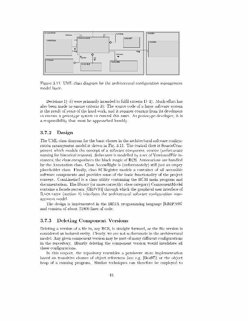
Figure 3.11: UML class diagram for the architectural con�guration management
model layer.
Decisions 1){5) were primarily intended to ful�l criteria 1){2). Much e�ort has
also been made to ensure criteria 3): The source code of a large software system
is the result of years of the hard work, and it requires courage from its developers
to entrust a prototype system to control this asset. As prototype developer, it is
a responsibility that must be approached humbly.
3.7.2 Design
The UML class diagram for the basic classes in the architectural software con�gu-
ration management model is shown in Fig. 3.11. The central class is SourceCom-
ponent which models the concept of a software component version (unfortunate
naming for historical reasons). Substance is modelled by a set of VersionedFile in-
stances; the class encapsulates the black magic of RCS. Annotations are handled
by the Annotation class. Class AccessRight is (unfortunately) still just an empty
placeholder class. Finally, class SCRegister models a container of all accessible
software components and provides some of the basic functionality of the project
concept. ComLineIntf is a class utility containing the RCM main program and
documentation. The library (or more correctly: class category) ComponentModel
contains a facade pattern [GHJV94] through which the graphical user interface of
Ragnarok (section 4) interfaces the architectural software con�guration man-
agement model.
The design is implemented in the BETA programming language [MMPN93]
and consists of about 21800 lines of code.
3.7.3 Deleting Component Versions
Deleting a version of a �le in, say RCS, is straight forward, as the �le version is
considered an isolated entity. Clearly, we are not so fortunate in the architectural
model: Any given component version may be part of many di�erent con�gurations
in the repository. Bluntly deleting the component version would invalidate all
these con�gurations.
In this respect, the repository resembles a persistent store implementation
based on transitive closure of object references (see e.g. [Bra97]) or the object
heap of a running program. Similar techniques can therefore be employed to
44
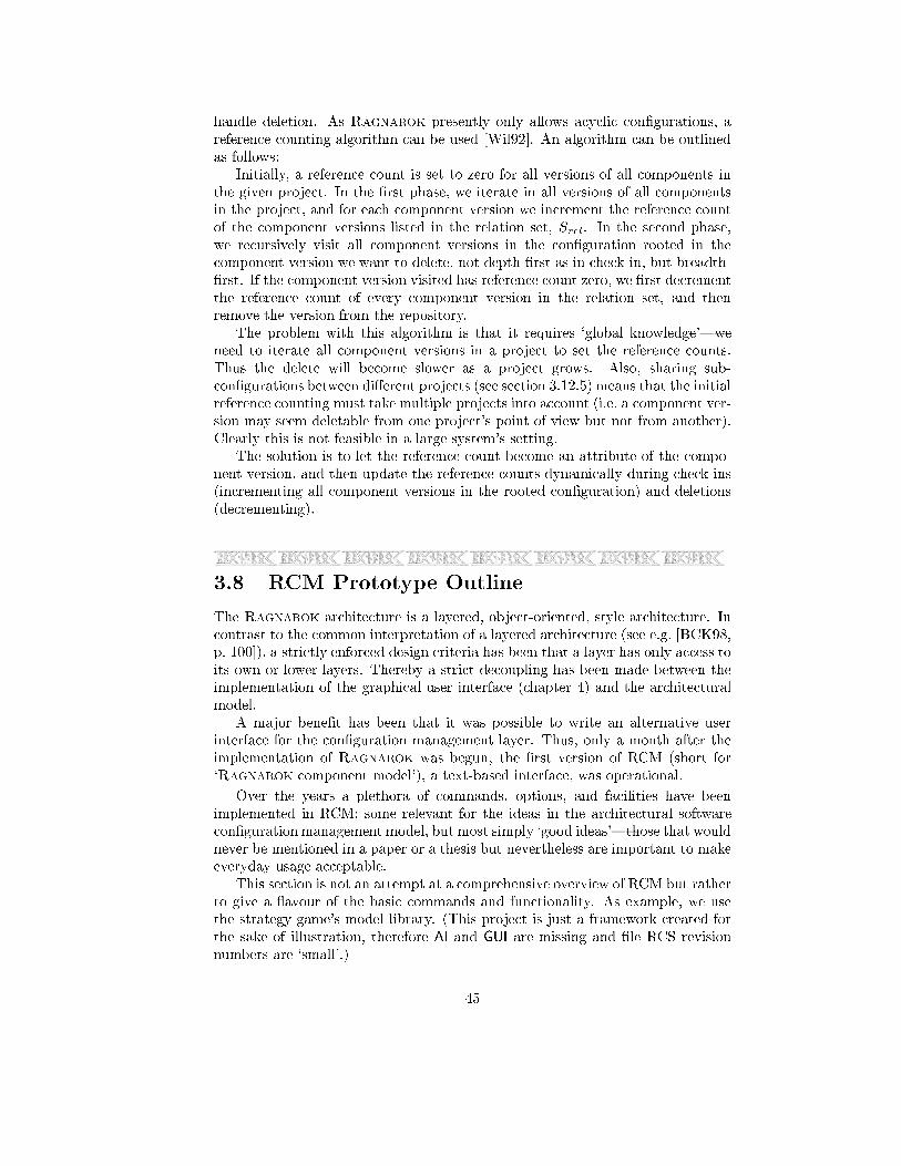
handle deletion. As Ragnarok presently only allows acyclic con�gurations, a
reference counting algorithm can be used [Wil92]. An algorithm can be outlined
as follows:
Initially, a reference count is set to zero for all versions of all components in
the given project. In the �rst phase, we iterate in all versions of all components
in the project, and for each component version we increment the reference count
of the component versions listed in the relation set, Srel. In the second phase,
we recursively visit all component versions in the con�guration rooted in the
component version we want to delete, not depth-�rst as in check-in, but breadth-
�rst. If the component version visited has reference count zero, we �rst decrement
the reference count of every component version in the relation set, and then
remove the version from the repository.
The problem with this algorithm is that it requires `global knowledge'|we
need to iterate all component versions in a project to set the reference counts.
Thus the delete will become slower as a project grows. Also, sharing sub-
con�gurations between di�erent projects (see section 3.12.5) means that the initial
reference counting must take multiple projects into account (i.e. a component ver-
sion may seem deletable from one project's point of view but not from another).
Clearly this is not feasible in a large system's setting.
The solution is to let the reference count become an attribute of the compo-
nent version, and then update the reference counts dynamically during check-ins
(incrementing all component versions in the rooted con�guration) and deletions
(decrementing).
3.8 RCM Prototype Outline
The Ragnarok architecture is a layered, object-oriented, style architecture. In
contrast to the common interpretation of a layered architecture (see e.g. [BCK98,
p. 100]), a strictly enforced design criteria has been that a layer has only access to
its own or lower layers. Thereby a strict decoupling has been made between the
implementation of the graphical user interface (chapter 4) and the architectural
model.
A major bene�t has been that it was possible to write an alternative user
interface for the con�guration management layer. Thus, only a month after the
implementation of Ragnarok was begun, the �rst version of RCM (short for
`Ragnarok component model'), a text-based interface, was operational.
Over the years a plethora of commands, options, and facilities have been
implemented in RCM; some relevant for the ideas in the architectural software
con�guration management model, but most simply `good ideas'|those that would
never be mentioned in a paper or a thesis but nevertheless are important to make
everyday usage acceptable.
This section is not an attempt at a comprehensive overview of RCM but rather
to give a avour of the basic commands and functionality. As example, we use
the strategy game's model library. (This project is just a framework created for
the sake of illustration, therefore AI and GUI are missing and �le RCS revision
numbers are `small'.)
45
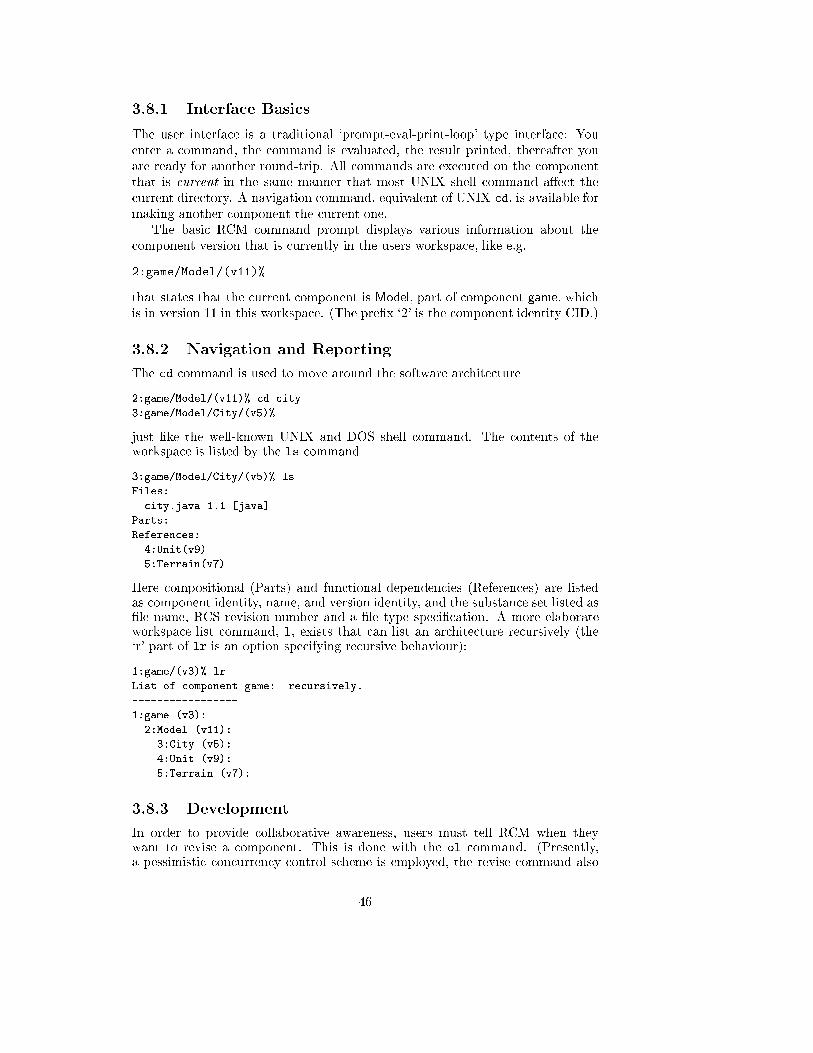
3.8.1 Interface Basics
The user interface is a traditional `prompt-eval-print-loop' type interface: You
enter a command, the command is evaluated, the result printed, thereafter you
are ready for another round-trip. All commands are executed on the component
that is current in the same manner that most UNIX shell command a�ect the
current directory. A navigation command, equivalent of UNIX cd, is available for
making another component the current one.
The basic RCM command prompt displays various information about the
component version that is currently in the users workspace, like e.g.
2:game/Model/(v11)%
that states that the current component is Model, part of component game, which
is in version 11 in this workspace. (The pre�x `2' is the component identity CID.)
3.8.2 Navigation and Reporting
The cd command is used to move around the software architecture
2:game/Model/(v11)% cd city
3:game/Model/City/(v5)%
just like the well-known UNIX and DOS shell command. The contents of theworkspace is listed by the ls command
3:game/Model/City/(v5)% ls
Files:
city.java 1.1 [java]
Parts:
References:
4:Unit(v9)
5:Terrain(v7)
Here compositional (Parts) and functional dependencies (References) are listedas component identity, name, and version identity, and the substance set listed as�le name, RCS revision number and a �le type speci�cation. A more elaborateworkspace list command, l, exists that can list an architecture recursively (the`r' part of lr is an option specifying recursive behaviour):
1:game/(v3)% lr
List of component game: recursively.
-----------------
1:game (v3):
2:Model (v11):
3:City (v5):
4:Unit (v9):
5:Terrain (v7):
3.8.3 Development
In order to provide collaborative awareness, users must tell RCM when theywant to revise a component. This is done with the ol command. (Presently,a pessimistic concurrency control scheme is employed, the revise command also
46
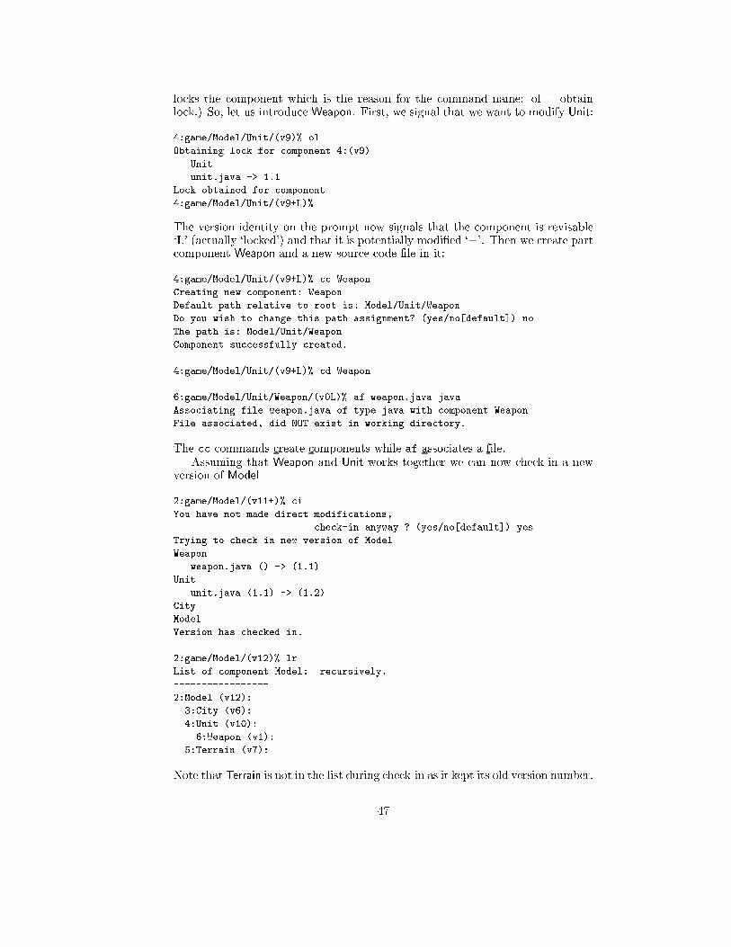
locks the component which is the reason for the command name: ol = obtainlock.) So, let us introduce Weapon. First, we signal that we want to modify Unit:
4:game/Model/Unit/(v9)% ol
Obtaining lock for component 4:(v9)
Unit
unit.java -> 1.1
Lock obtained for component
4:game/Model/Unit/(v9+L)%
The version identity on the prompt now signals that the component is revisable`L' (actually `locked') and that it is potentially modi�ed `+'. Then we create partcomponent Weapon and a new source code �le in it:
4:game/Model/Unit/(v9+L)% cc Weapon
Creating new component: Weapon
Default path relative to root is: Model/Unit/Weapon
Do you wish to change this path assignment? (yes/no[default]) no
The path is: Model/Unit/Weapon
Component successfully created.
4:game/Model/Unit/(v9+L)% cd Weapon
6:game/Model/Unit/Weapon/(v0L)% af weapon.java java
Associating file weapon.java of type java with component Weapon
File associated, did NOT exist in working directory.
The cc commands create components while af associates a file.Assuming that Weapon and Unit works together we can now check-in a new
version of Model
2:game/Model/(v11+)% ci
You have not made direct modifications,
check-in anyway ? (yes/no[default]) yes
Trying to check in new version of Model
Weapon
weapon.java () -> (1.1)
Unit
unit.java (1.1) -> (1.2)
City
Model
Version has checked in.
2:game/Model/(v12)% lr
List of component Model: recursively.
-----------------
2:Model (v12):
3:City (v6):
4:Unit (v10):
6:Weapon (v1):
5:Terrain (v7):
Note that Terrain is not in the list during check-in as it kept its old version number.
47
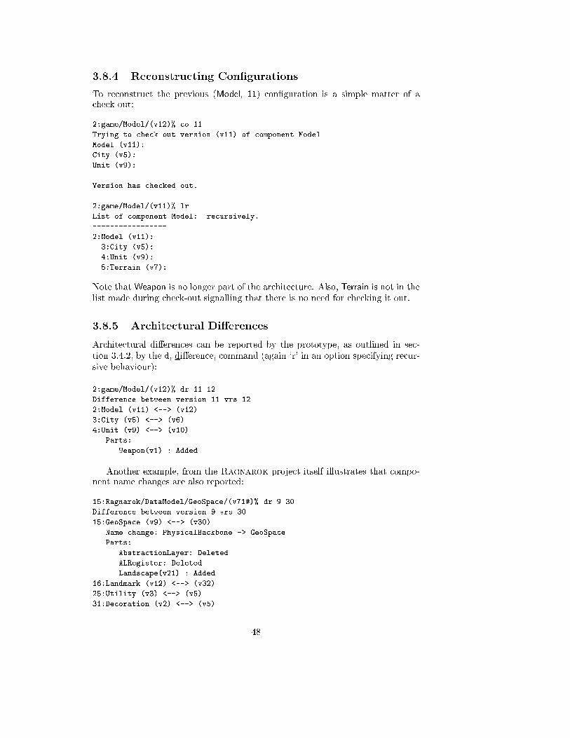
3.8.4 Reconstructing Con�gurations
To reconstruct the previous (Model, 11) con�guration is a simple matter of acheck-out:
2:game/Model/(v12)% co 11
Trying to check out version (v11) of component Model
Model (v11):
City (v5):
Unit (v9):
Version has checked out.
2:game/Model/(v11)% lr
List of component Model: recursively.
-----------------
2:Model (v11):
3:City (v5):
4:Unit (v9):
5:Terrain (v7):
Note that Weapon is no longer part of the architecture. Also, Terrain is not in the
list made during check-out signalling that there is no need for checking it out.
3.8.5 Architectural Di�erences
Architectural di�erences can be reported by the prototype, as outlined in sec-
tion 3.4.2, by the d, di�erence, command (again `r' in an option specifying recur-
sive behaviour):
2:game/Model/(v12)% dr 11 12
Difference between version 11 vrs 12
2:Model (v11) <--> (v12)
3:City (v5) <--> (v6)
4:Unit (v9) <--> (v10)
Parts:
Weapon(v1) : Added
Another example, from the Ragnarok project itself illustrates that compo-nent name changes are also reported:
15:Ragnarok/DataModel/GeoSpace/(v71#)% dr 9 30
Difference between version 9 vrs 30
15:GeoSpace (v9) <--> (v30)
Name change: PhysicalBackbone -> GeoSpace
Parts:
AbstractionLayer: Deleted
ALRegister: Deleted
Landscape(v21) : Added
16:Landmark (v12) <--> (v32)
25:Utility (v3) <--> (v5)
31:Decoration (v2) <--> (v5)
48
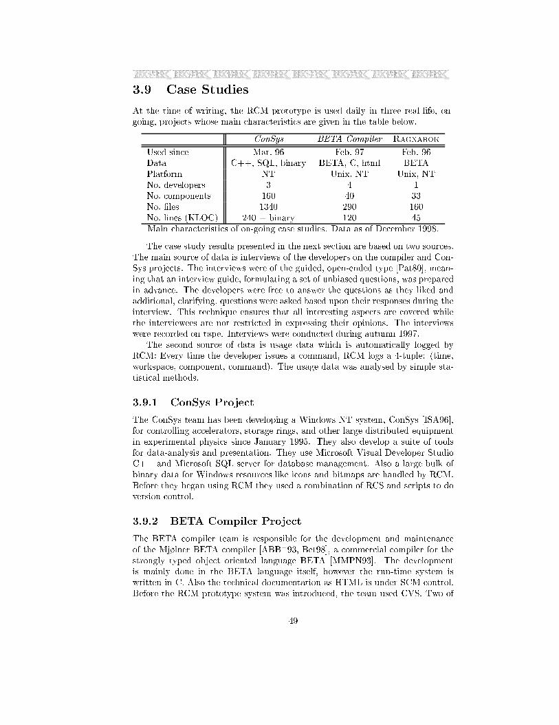
3.9 Case Studies
At the time of writing, the RCM prototype is used daily in three real-life, on-
going, projects whose main characteristics are given in the table below.
ConSys BETA Compiler Ragnarok
Used since Mar. 96 Feb. 97 Feb. 96
Data C++, SQL, binary BETA, C, html BETA
Platform NT Unix, NT Unix, NT
No. developers 3 4 1
No. components 160 40 33
No. �les 1340 290 160
No. lines (KLOC) 240 + binary 120 45
Main characteristics of on-going case studies. Data as of December 1998.
The case study results presented in the next section are based on two sources.
The main source of data is interviews of the developers on the compiler and Con-
Sys projects. The interviews were of the guided, open-ended type [Pat80], mean-
ing that an interview guide, formulating a set of unbiased questions, was prepared
in advance. The developers were free to answer the questions as they liked and
additional, clarifying, questions were asked based upon their responses during the
interview. This technique ensures that all interesting aspects are covered while
the interviewees are not restricted in expressing their opinions. The interviews
were recorded on tape. Interviews were conducted during autumn 1997.
The second source of data is usage data which is automatically logged by
RCM: Every time the developer issues a command, RCM logs a 4-tuple: (time,
workspace, component, command). The usage data was analysed by simple sta-
tistical methods.
3.9.1 ConSys Project
The ConSys team has been developing a Windows NT system, ConSys [ISA96],
for controlling accelerators, storage rings, and other large distributed equipment
in experimental physics since January 1995. They also develop a suite of tools
for data-analysis and presentation. They use Microsoft Visual Developer Studio
C++ and Microsoft SQL server for database management. Also a large bulk of
binary data for Windows resources like icons and bitmaps are handled by RCM.
Before they began using RCM they used a combination of RCS and scripts to do
version control.
3.9.2 BETA Compiler Project
The BETA compiler team is responsible for the development and maintenance
of the Mj�lner BETA compiler [ABB+93, Bet98], a commercial compiler for the
strongly typed object oriented language BETA [MMPN93]. The development
is mainly done in the BETA language itself, however the run-time system is
written in C. Also the technical documentation as HTML is under SCM control.
Before the RCM prototype system was introduced, the team used CVS. Two of
49
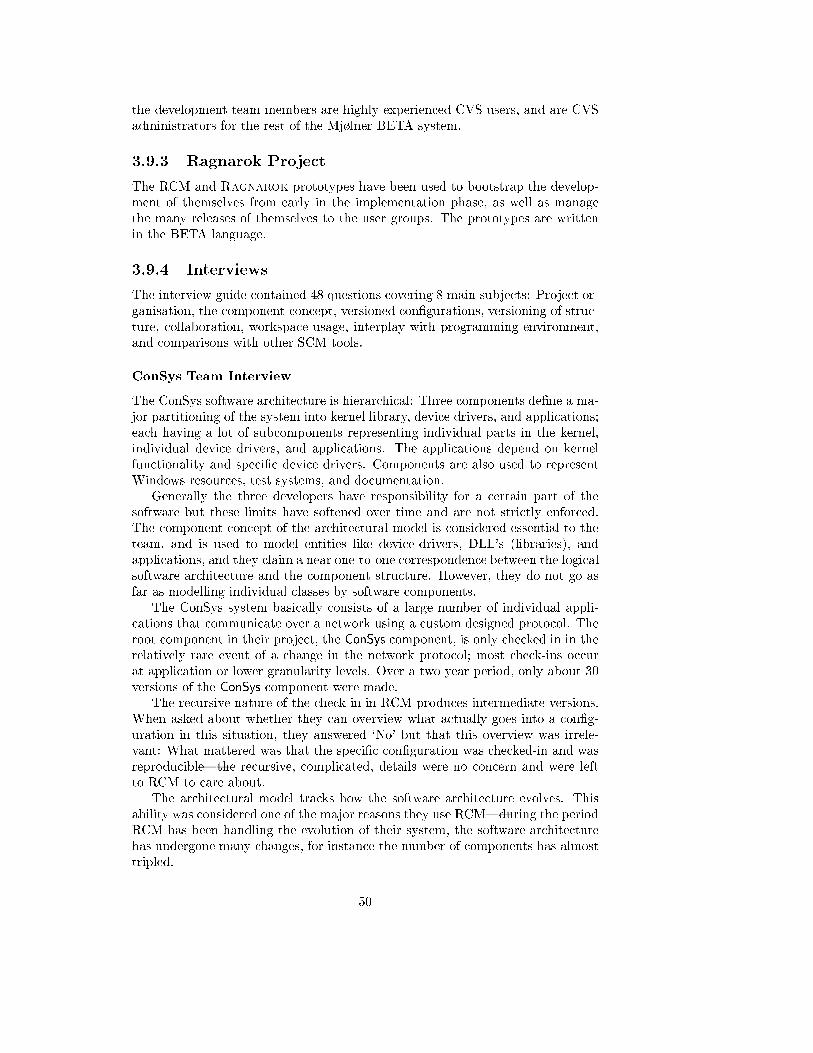
the development team members are highly experienced CVS users, and are CVS
administrators for the rest of the Mj�lner BETA system.
3.9.3 Ragnarok Project
The RCM and Ragnarok prototypes have been used to bootstrap the develop-
ment of themselves from early in the implementation phase, as well as manage
the many releases of themselves to the user groups. The prototypes are written
in the BETA language.
3.9.4 Interviews
The interview guide contained 48 questions covering 8 main subjects: Project or-
ganisation, the component concept, versioned con�gurations, versioning of struc-
ture, collaboration, workspace usage, interplay with programming environment,
and comparisons with other SCM tools.
ConSys Team Interview
The ConSys software architecture is hierarchical: Three components de�ne a ma-
jor partitioning of the system into kernel library, device drivers, and applications;
each having a lot of subcomponents representing individual parts in the kernel,
individual device drivers, and applications. The applications depend on kernel
functionality and speci�c device drivers. Components are also used to represent
Windows resources, test systems, and documentation.
Generally the three developers have responsibility for a certain part of the
software but these limits have softened over time and are not strictly enforced.
The component concept of the architectural model is considered essential to the
team, and is used to model entities like device-drivers, DLL's (libraries), and
applications, and they claim a near one-to-one correspondence between the logical
software architecture and the component structure. However, they do not go as
far as modelling individual classes by software components.
The ConSys system basically consists of a large number of individual appli-
cations that communicate over a network using a custom designed protocol. The
root component in their project, the ConSys component, is only checked in in the
relatively rare event of a change in the network protocol; most check-ins occur
at application or lower granularity levels. Over a two year period, only about 30
versions of the ConSys component were made.
The recursive nature of the check-in in RCM produces intermediate versions.
When asked about whether they can overview what actually goes into a con�g-
uration in this situation, they answered `No' but that this overview was irrele-
vant: What mattered was that the speci�c con�guration was checked-in and was
reproducible|the recursive, complicated, details were no concern and were left
to RCM to care about.
The architectural model tracks how the software architecture evolves. This
ability was considered one of the major reasons they use RCM|during the period
RCM has been handling the evolution of their system, the software architecture
has undergone many changes, for instance the number of components has almost
tripled.
50

To sum up, the team is positive towards the architectural model in spite of the
limitations of the RCM tool. The component idea, the ability to have a one-to-
one correspondence between the logical software design and the SCM model, and
the exible handling of an evolving structure were especially emphasised. The
critics they had were towards the current implementation, lack of features, and
the current use of a per-component locking scheme during revise operations|and
not towards fundamental aspects of the model.
As a closing remark it was interesting to note that they claimed that they use
the concept `component' strictly when discussing SCM issues while using concepts
like `DLL', `application', and `drivers' when discussing implementation and design.
Several times during the interview, however, the developers themselves said things
like `: : : when I rewrote the GUI component from scratch'. We take this as
an indication that the architectural model indeed succeeds in providing SCM
concepts that maps closely to the normal, mental, model of software design.
BETA Compiler Team Interview
The compiler software architecture is hierarchical: The compiler application is
divided into a checker, synthesiser, controller, and generator, the latter having a
lot of part components for the machine architectures and operating systems, the
compiler is available for. Components are also used for HTML documentation
and experimental work with dynamic compilation and linkage.
Generally each person in the team has responsibility for a speci�c part of the
project code. The component idea suits their way of working, and components
are claimed to model logical parts of the compiler design in the SCM framework.
In contrast with the ConSys team, check-in is almost always made from the
root component, in the Compiler component. As this project consists of a single
application, as opposed to ConSys, this approach seems natural, but of course
produces a vast number of root components, about 600 over a two year period.
The strong focus on versioning full con�gurations was considered important.
Interestingly, they had not used the facility much, but the mere knowledge that
their system was under tight control, made the developers fell secure. They
stressed the e�ortless ability to retract to earlier versions, and that if they knew
of one version of a �le that was `OK', it is a simple exercise using RCM's ver-
sion graphs and query facilities to identify the exact con�guration it was part
of. This was contrasted to CVS where the relations between �le versions and
con�gurations, and the version graph was, quote, `black magic'.
The compiler team also reported that they had virtually no overview over
the internal, recursive, relations between component versions, but that it was
irrelevant and `the job of the tool'.
Tracking the evolution of the architecture itself, new �les and libraries, was
also considered important|an aspect that they reported CVS to handle poorly
or even wrongly. They emphasised the need for tracking the version history of
a �le and component across renames and movement within the software archi-
tecture; functionality the current implementation unfortunately does not provide
adequately.
The team was asked to identify strong and weak points in the model compared
to the CVS model. The major critics was the inability to write scripts that exercise
51
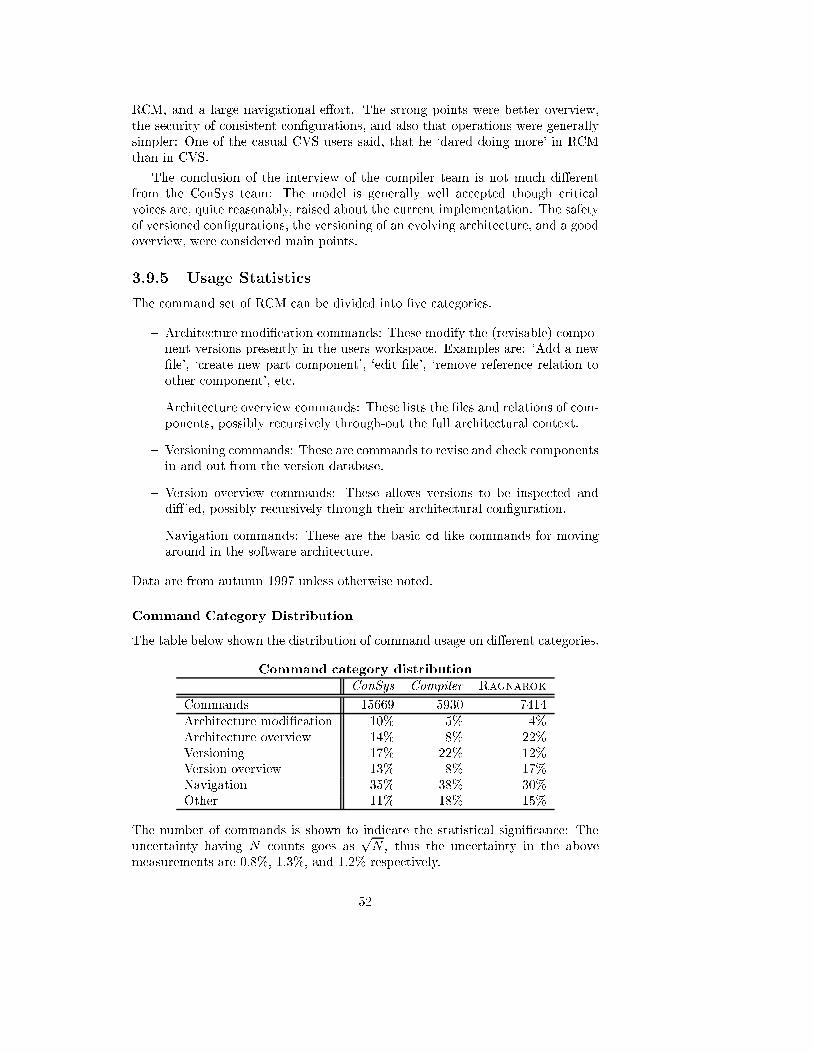
RCM, and a large navigational e�ort. The strong points were better overview,
the security of consistent con�gurations, and also that operations were generally
simpler: One of the casual CVS users said, that he `dared doing more' in RCM
than in CVS.
The conclusion of the interview of the compiler team is not much di�erent
from the ConSys team: The model is generally well accepted though critical
voices are, quite reasonably, raised about the current implementation. The safety
of versioned con�gurations, the versioning of an evolving architecture, and a good
overview, were considered main points.
3.9.5 Usage Statistics
The command set of RCM can be divided into �ve categories.
{ Architecture modi�cation commands: These modify the (revisable) compo-
nent versions presently in the users workspace. Examples are: `Add a new
�le', `create new part component', `edit �le', `remove reference relation to
other component', etc.
{ Architecture overview commands: These lists the �les and relations of com-
ponents, possibly recursively through-out the full architectural context.
{ Versioning commands: These are commands to revise and check components
in and out from the version database.
{ Version overview commands: These allows versions to be inspected and
di�'ed, possibly recursively through their architectural con�guration.
{ Navigation commands: These are the basic cd like commands for moving
around in the software architecture.
Data are from autumn 1997 unless otherwise noted.
Command Category Distribution
The table below shown the distribution of command usage on di�erent categories.
Command category distribution
ConSys Compiler Ragnarok
Commands 15669 5930 7414
Architecture modi�cation 10% 5% 4%
Architecture overview 14% 8% 22%
Versioning 17% 22% 12%
Version overview 13% 8% 17%
Navigation 35% 38% 30%
Other 11% 18% 15%
The number of commands is shown to indicate the statistical signi�cance: The
uncertainty having N counts goes aspN , thus the uncertainty in the above
measurements are 0.8%, 1.3%, and 1.2% respectively.
52
The large percentage of navigation commands is prominent: In all projects
the cd command is by far the most used command. The visualisation system in
Ragnarok (see chapter 4) reduces the navigational e�ort signi�cantly.
Secondly, it is apparent that the architectures of the projects have evolved
quite a lot|for instance in the ConSys project about 1560 commands have been
issued that modify the software architecture. For the compiler and Ragnarok
projects it is about 300 changes each. This supports the statements given in the
interview by the ConSys team concerning the value of supporting an evolving
architecture.
Parameterised Commands
A small set of the commands accepts options, these are the architecture overview,
version overview, and di� commands. The options determine if the command
displays information for the current component only, or recursively for the con-
�guration rooted in the current component; and if substance (�le) information
should be reported or not. The recursive option `r' given to the list and di�erence
commands of RCM in section 3.8 is an example of the former.
Parameter distribution
ConSys Compiler Ragnarok
Parameterised commands issued 799 276 1148
Rooted con�guration pct. 83% 71% 58%
File information pct. 11% 8% 15%
The three rows state the count of parameterised commands issued in the three
projects and the percentage of these that was issued with the rooted con�gura-
tion traversal- and display �le information-option respectively. As the counts are
fairly high the uncertainties are low, about 4%, 6%, and 3% respectively for the
three projects. Thus the numbers show with high signi�cance that the overview
commands are used to overview the software architecture whereas less attention is
paid to the actual �les making up the components substance. Again this indicates
that the architectural SCM model relieves developers from thinking in �les.
Intermediate Version Number Growth
As detailed in section 3.10.2, critical voices are often raised concerning the fact
that SCM models that operate on the transitive re exive closure create interme-
diate versions: Those new component versions that must be created along the
path from the component that receives the check-in command to the components
where actual changes have been made. The argument is that they may confuse
the user, pollute the version graphs, take up storage space, and their number
explode combinatorially [CW98, x4.1]. As described above, the user groups did
not agree with this argument.
To get some statistical feel of the problem, RCM was equipped with a com-
mand that performs a sweep of all component versions in the repository and
counts their number and the number of component versions that are origins (an
origin component version is de�ned as the component version that becomes the
53
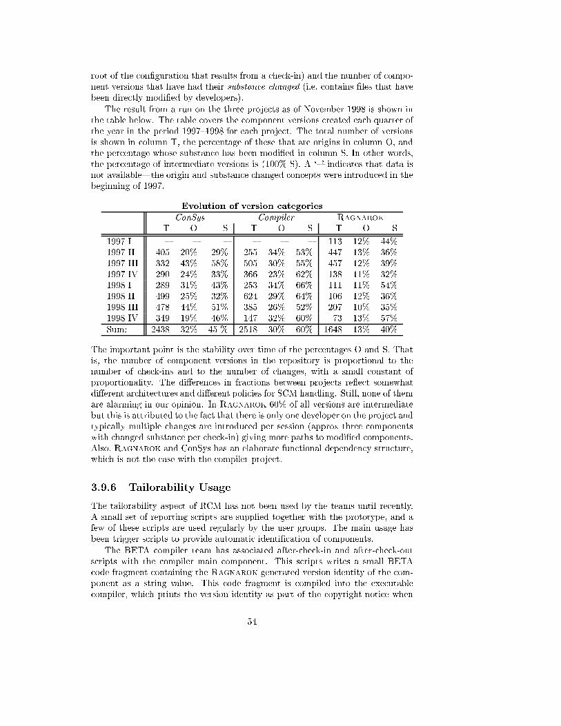
root of the con�guration that results from a check-in) and the number of compo-
nent versions that have had their substance changed (i.e. contains �les that have
been directly modi�ed by developers).
The result from a run on the three projects as of November 1998 is shown in
the table below. The table covers the component versions created each quarter of
the year in the period 1997{1998 for each project. The total number of versions
is shown in column T, the percentage of these that are origins in column O, and
the percentage whose substance has been modi�ed in column S. In other words,
the percentage of intermediate versions is (100%-S). A `{' indicates that data is
not available|the origin and substance changed concepts were introduced in the
beginning of 1997.
Evolution of version categories
ConSys Compiler Ragnarok
T O S T O S T O S
1997 I { { { { { { 113 12% 44%
1997 II 405 20% 29% 255 34% 53% 447 13% 36%
1997 III 332 43% 58% 505 30% 55% 457 12% 39%
1997 IV 290 24% 33% 366 23% 62% 138 11% 32%
1998 I 289 31% 43% 253 34% 66% 111 11% 54%
1998 II 499 25% 32% 624 29% 64% 106 12% 36%
1998 III 478 44% 51% 385 26% 52% 207 10% 35%
1998 IV 349 19% 46% 147 32% 60% 73 13% 57%
Sum: 2438 32% 45 % 2518 30% 60% 1648 13% 40%
The important point is the stability over time of the percentages O and S. That
is, the number of component versions in the repository is proportional to the
number of check-ins and to the number of changes, with a small constant of
proportionality. The di�erences in fractions between projects re ect somewhat
di�erent architectures and di�erent policies for SCM handling. Still, none of them
are alarming in our opinion. In Ragnarok 60% of all versions are intermediate
but this is attributed to the fact that there is only one developer on the project and
typically multiple changes are introduced per session (approx three components
with changed substance per check-in) giving more paths to modi�ed components.
Also, Ragnarok and ConSys has an elaborate functional dependency structure,
which is not the case with the compiler project.
3.9.6 Tailorability Usage
The tailorability aspect of RCM has not been used by the teams until recently.
A small set of reporting scripts are supplied together with the prototype, and a
few of these scripts are used regularly by the user groups. The main usage has
been trigger scripts to provide automatic identi�cation of components.
The BETA compiler team has associated after-check-in and after-check-out
scripts with the compiler main component. This scripts writes a small BETA
code fragment containing the Ragnarok generated version identity of the com-
ponent as a string value. This code fragment is compiled into the executable
compiler, which prints the version identity as part of the copyright notice when
54
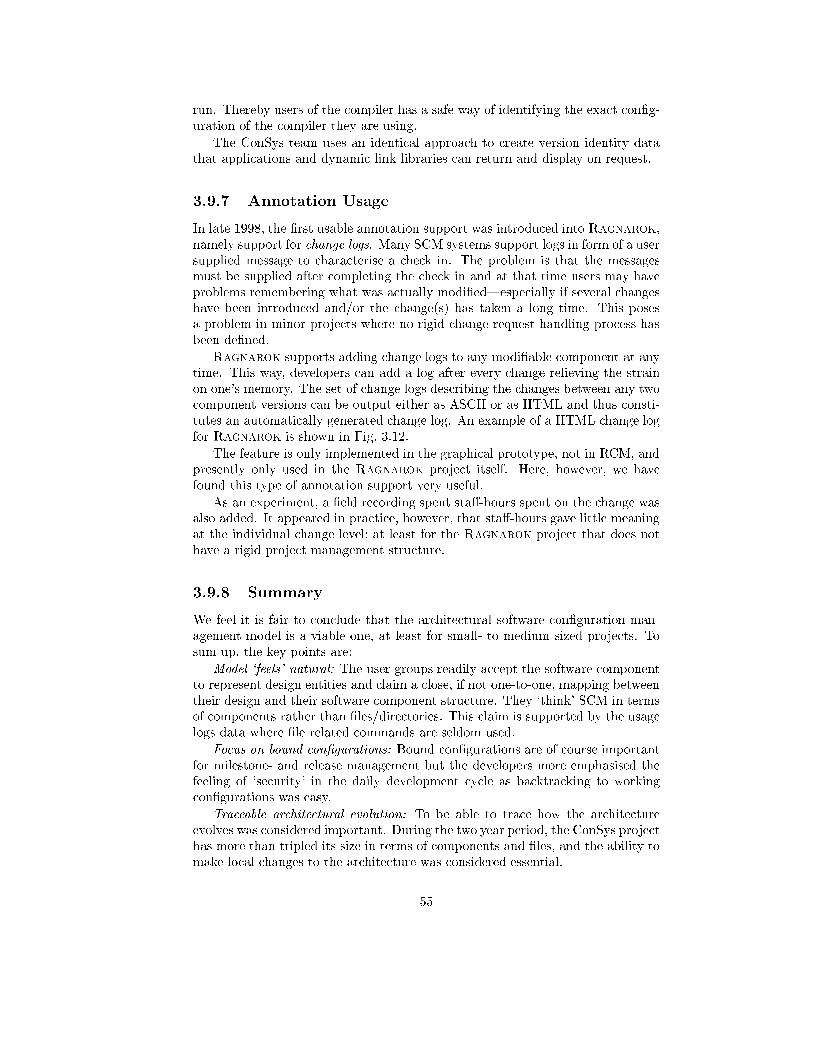
run. Thereby users of the compiler has a safe way of identifying the exact con�g-
uration of the compiler they are using.
The ConSys team uses an identical approach to create version identity data
that applications and dynamic link libraries can return and display on request.
3.9.7 Annotation Usage
In late 1998, the �rst usable annotation support was introduced into Ragnarok,
namely support for change logs. Many SCM systems support logs in form of a user
supplied message to characterise a check in. The problem is that the messages
must be supplied after completing the check in and at that time users may have
problems remembering what was actually modi�ed|especially if several changes
have been introduced and/or the change(s) has taken a long time. This poses
a problem in minor projects where no rigid change request handling process has
been de�ned.
Ragnarok supports adding change logs to any modi�able component at any
time. This way, developers can add a log after every change relieving the strain
on one's memory. The set of change logs describing the changes between any two
component versions can be output either as ASCII or as HTML and thus consti-
tutes an automatically generated change log. An example of a HTML change log
for Ragnarok is shown in Fig. 3.12.
The feature is only implemented in the graphical prototype, not in RCM, and
presently only used in the Ragnarok project itself. Here, however, we have
found this type of annotation support very useful.
As an experiment, a �eld recording spent sta�-hours spent on the change was
also added. It appeared in practice, however, that sta�-hours gave little meaning
at the individual change level; at least for the Ragnarok project that does not
have a rigid project management structure.
3.9.8 Summary
We feel it is fair to conclude that the architectural software con�guration man-
agement model is a viable one, at least for small- to medium sized projects. To
sum up, the key points are:
Model `feels' natural: The user groups readily accept the software component
to represent design entities and claim a close, if not one-to-one, mapping between
their design and their software component structure. They `think' SCM in terms
of components rather than �les/directories. This claim is supported by the usage
logs data where �le related commands are seldom used.
Focus on bound con�gurations: Bound con�gurations are of course important
for milestone- and release management but the developers more emphasised the
feeling of `security' in the daily development cycle as backtracking to working
con�gurations was easy.
Traceable architectural evolution: To be able to trace how the architecture
evolves was considered important. During the two year period, the ConSys project
has more than tripled its size in terms of components and �les, and the ability to
make local changes to the architecture was considered essential.
55
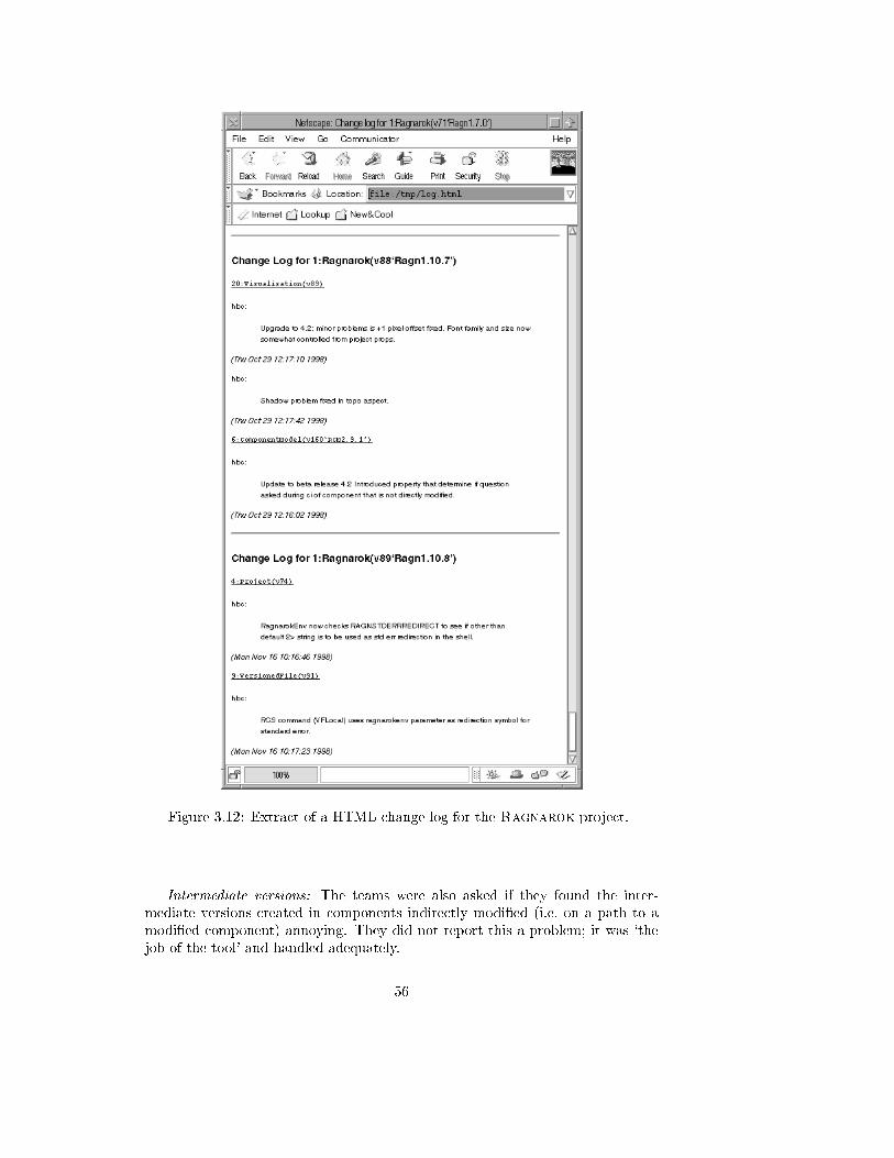
Figure 3.12: Extract of a HTML change log for the Ragnarok project.
Intermediate versions: The teams were also asked if they found the inter-
mediate versions created in components indirectly modi�ed (i.e. on a path to a
modi�ed component) annoying. They did not report this a problem; it was `the
job of the tool' and handled adequately.
56
3.10 Discussion
The Ragnarok architectural model is characterised by:
{ The component concept that allows code fragments and related data to be
treated as a cohesive whole under version control.
{ Relations that state relationships between speci�c states (versions) of com-
ponents.
{ Transitive algorithms meaning that the repository stores bound, rooted,
con�gurations and therefore the concepts version and bound con�guration
are uni�ed.
In terms of usability of the model, these properties lead to:
{ A model that is easy to learn. Fewer concepts are introduced than in many
other SCM systems; basically only the notion of component and version.
{ The introduced concepts map to concepts in the development domain: Com-
ponents to abstractions, and rooted con�gurations to the dependency graph.
Versions are a quite natural extension when one tries to capture evolution.
{ The model provides the well-proven concepts of encapsulation and mod-
ularisation at the software con�guration management level. A software
component version encapsulates a version of an abstraction and hides the
potentially highly complicated set of abstractions depended upon and their
internal relationships.
{ The architectural description is distributed (relations are stated locally to
the components they a�ect) thus no global description becomes a bottleneck
(exempli�ed by for instance make�les).
{ Reproducibility: Any con�guration that has been checked in, the model is
able to reconstruct exactly. This property is important in release situations,
but also provides security in daily work.
{ Architectural evolution is captured in the evolution of the rooted con�gu-
rations, including relationships between components, which is a simple and
natural way.
{ Di�erences between versions/con�gurations can be reported on a high, ar-
chitectural, level as opposed to simple �le contents di�erences.
The continued use of the prototypes shows that such a model is viable, at least
for small- to medium-sized software development projects. User groups report
that the model feels `natural' and value the emphasis on bound con�gurations
and architectural evolution.
57
3.10.1 Classifying the Version Model
One of the �rst attempts to provide a common terminology for SCM and a frame-
work for comparing di�erent SCM tools was Tichy's paper at the Grassau SCM-
2 workshop [Tic88]. Since this seminal work several researchers have followed
up: The overview by Estublier [Est88], Katz's work on version control in the
context of CAD [Kat90], Feiler's classi�cations of SCM systems [Fei91], Dart's
historical review [Dar91], and lately Conradi and Westfechtel have focused on
the version control aspect of SCM and have aimed at providing a uni�ed version
model [CW97, CW98]. Especially the 1998 paper is a thorough and comprehen-
sive study of the version models employed in SCM systems over the last twenty
years. They set up a classi�cation scheme, partially based on the AND/OR graph
of Tichy (see sidebar 3.1 on p. 76). Using this scheme, the Ragnarok architec-
tural versioning model can be described as an extensional versioning, version �rst
selection, total versioning model:
Extensional versioning: A version group V is de�ned by enumerating its mem-
bers: V = fv1; v2; : : : ; vng. This is in contrast to intensional versioning where V
is de�ned implicitly by a predicate c: V = fv j c(v)g; c de�nes the constraints
that must be satis�ed by all members of V . Here speci�c versions are described
intensionally, i.e. constructed in response to some query ([CW98, p. 239-240]).
Version �rst selection: This property re ects the order of selection between
product structure and versions. In product �rst, the product structure is selected
�rst and versions of components selected subsequently; the standard example
is `make' combined with RCS/SCCS/CVS. In version �rst, one �rst selects a
`product' version which then uniquely determines the component versions and
the structure; an example is (Model, 11) and (Model, 12) (Fig. 3.2 and 3.3 on
pages 26 and 29) that are versions uniquely identifying di�erent product structures
([CW98, p. 245-246]); one with and one without Weapon.
Total versioning: This property re ects the version granularity and how exter-
nal versioning is applied to the software architecture. In component versioning
only atomic objects are under version control (typically �les; again RCS is an
example as RCS has no direct way of specifying versions of composites like a
directory); thus the version graphs of di�erent components are weakly related.
In total versioning all entities are uniformly versioned i.e. versions of composite
objects are also explicitly represented; for instance Model will probably not con-
tain any substance, its only (but critical) purpose is as a composite, de�ning the
library encapsulating the relevant classes. ([CW98, p. 248-249])
3.10.2 The Intermediate Version Debate
Versioning models with version �rst selection create versions of all components on
a path to a modi�ed one|even if they have not been changed directly themselves.
The creation of (City, 6) in Fig. 3.3 (p. 29) is a good example: Even if we make
no changes in the source code of City, a new version is created nevertheless.
We have termed such versions `intermediate', in literature the e�ect is known as
version proliferation. We have deliberately avoided the term `proliferation' as it
is negatively charged which we �nd unfair.
58
Conradi and Westfechtel see intermediate versions as a problem at the logical
level:
... the user is confronted with a combinatorially exploding number
of versions. To get rid of version proliferation at the logical level,
we have to distinguish between versions of modules and versions of
con�gurations.[CW98, x4.1]
Obviously, we think this viewpoint is wrong. We argue in favour of a version
�rst selection scheme for the following reasons:
1. The versions created are necessary and needed as concrete objects repre-
senting meaningful sub-con�gurations.
2. There is no `exploding number of versions'; though the approach does create
more versions than other version selection schemes, any sensible architecture
and working process will certainly not see a combinatorial explosion.
3. There is no problem at the implementation level (this point is also argued
by Conradi and Westfechtel).
4. The space overhead of intermediate versions is small.
5. Users of the Ragnarok prototype did not report the extra versions a prob-
lem.
6. Finally, what is the cost of avoiding the problem?
Ad. 1: Versions created serve an important purpose as they are �rst class objects
that identify parts of con�gurations. Returning to our example in Fig. 3.3, (City, 6)
is a concrete objects that is the version of City that is part of (Model, 12)|allowing
us to identify, inspect, and reason about the properties of this sub-con�guration.
Ad. 2: Changes do not necessarily result in intermediate versions; many changes
can be made independently in sub-con�gurations before they are `frozen' by a
check-in at a higher level component. Figure 3.7 (p. 36) hints at this, the major
restructuring of class Terrain is a long process producing intermediate versions
representing more and more re�ned states. But as the check-in is done at the
granularity of the Terrain component, no additional versions of Model, City, etc.,
are produced.
Secondly, sensibly arranged architectures do not experience a combinatorial
explosion of versions. The reported data from the Ragnarok user groups (sec-
tion 3.9.5) shows a constant ratio over time between the number of `required'
versions and intermediate versions.
Ad. 3: Several working implementations, based on version �rst selection, exists.
Apart from Ragnarok, section 3.11 has a comprehensive list of these implemen-
tations.
Ad. 4: Versions of components that have not experienced direct substance
changes only di�er from their ancestor versions in the contents of the relation
set (and possibly some housekeeping information like date, author, etc.). There-
fore, the di�erence between two versions (the delta) is small.
Ad. 5: As described in section 3.9 neither of the RCM user groups considered it
a problem.
59
Ad. 6: Basically, it is wrong just to characterise the proliferation as a `prob-
lem'. Rather, it is a trade-o�. As Conradi and Westfechtel write `. . . we have to
distinguish between versions of modules and versions of con�gurations' to avoid
creating extra versions. In other words, the cost of avoiding them is to introduce
additional constructs like separately versioned con�guration items, tags, or rule-
based selection engines, to handle de�ning con�gurations and controlling their
evolution. Thus, developers have to master more concepts|concepts that have
no simple equivalence to development domain concepts. We happily trade disc
space for the simplicity of version �rst selection systems.
3.10.3 Pollution by Intermediate Versions
It should not be neglected that there is a point in the critique of intermediate
e�ect versions: It is confusing that there may be many versions of a component
where the substance are identical. This constitutes a pollution of the version
graph for a given component as intentional and intermediate versions are mixed.
Another problem is that the version intention, often stated in the `log message'
produced at the time of check-in, is stored in the root component version in the
resulting con�guration; that is the intermediate component versions do not have
access to this description directly.
The current implementation of Ragnarok maintains two additional at-
tributes of each component version that can be useful to answer such questions
and provide the basis for a future Ragnarok version that can reduce and or-
ganise the information presented to the user in a relevant way. The are also the
attributes that allowed the statistical measurements outlined in section 3.9.5.
{ Boolean value SubstanceChanged that is true i� the substance attribute of
the component version has changed compared to its ancestor.
{ Component version reference CheckInOrigin that refers to the component
version that is the root of the con�guration, this (potentially intermediate)
component version became part of.
The �rst attribute can be used to contract successive component versions
without any changes to the substance into `super'-versions, a feature explored in
e.g. CoEd [BLNP98]. This reduces the size of the apparent version graph7.
The second attribute supports �nding the intention for the version: Through
the origin reference one can access, e.g. the symbolic name and log message per-
tinent for the component version even if these are stored in another component
version.
The two attributes are the ones that allowed the statistical measurements
outlined in section 3.9.5.
3.10.4 On Development Process
The architectural model addresses data version- and con�guration control, but
does not address the issue of development process control: It neither provides nor
dictates one.
7Implementation note: This feature is operational in RCM.
60
Still, the process is important and in practice di�erent kinds of policies arise
naturally when working with Ragnarok and RCM.
Policy and Consistency
In section 3.2 and section 3.3 the notion of consistency of con�gurations, of
workspaces and of the repository was introduced, through requirements 3.1{3.5.
However, this notion focuses purely on aspects of the SCM data-structures, it
does not address the question of `consistency' of the underlying substance in the
components: It is fully possible to check-in a con�guration of component versions
whose substance contains a completely inconsistent and invalid set of source code
fragments in the sense that the resulting software does not compile, link, or in
other ways does not ful�l its requirements. It is an important part of the team
policy to de�ne what requirements must be ful�lled by the source code before it
is legal to perform a check-in.
In Ragnarok a viable policy is the one outlined in section 3.5 about branch-
ing and merging architectures, i.e. a process where developers (or sub-teams)
work quite independently on sub-con�gurations and occasionally do integration
testing by communicating the version identi�cation of the rooted con�guration.
This policy allows the individual/subteam free hands in de�ning what constitutes
a new version: As other individuals or teams are only supposed to check-out a
small number of speci�c con�gurations, it opens up for creating versions serving
as convenient snapshots, partial goals achieved, etc.
None of the two teams have adopted this policy, however. Instead, they inte-
grate often with the newest available code for every part of the system. This is
especially pronounced in the BETA compiler team. As a consequence, the teams
have adopted a policy where it is only allowed to check-in if the source-code links,
compiles, is logically correct and in other respects `well-behaved'. This policy
necessarily reduces the exibility in the use of versioning.
A more stringent, and Ragnarok controlled, approval process can be en-
visioned by extending the tailorability aspects of Ragnarok(section 3.6). For
instance, triggered scripts can be allowed to in uence the check-in process based
on various properties of the con�guration, such as aborting the check-in if there
are test program that have not been run, code metrics, etc.
Granularity of Check-In
An interesting question is the following: Given a change request has been im-
plemented in a given component or set of components, then at what level of
granularity should the check-in be issued? Ragnarok is very exible in this re-
spect. Consider again the introduction of the Weapon class in class Unit, sketched
in Fig. 3.2 and Fig. 3.3, in section 3.3. The section discussed this change view-
ing it as a change to the Model library, and therefore it was natural to issue the
check-in to component Model. However, one could easily argue that this change
should be checked-in at the Unit component level, or at the Game level. Again,
it is part of team policy and social protocol to de�ne the `right' granularity of
check-in for di�erent types of changes. Interestingly, the three user groups have
arrived at quite di�erent policies.
61
The BETA compiler team is in this aspect quite `extreme' in that any change
is always checked-in from the root component. This policy re ects the standpoint
that the compiler is a single entity, and therefore the only relevant version history
is that of the compiler as a whole. The version graph of the root component plays
this role.
The ConSys project consists of a number of separate applications, commu-
nicating through a common protocol, and drawing upon base functionality in a
number of core (dynamic link) libraries and device drivers. Most applications
deal with data from a very limited part of the physical system, typically acqui-
sition of raw data from a single instrument, and is thus largely independent of
other applications. Consequently, check-ins are typically made at many levels:
At the individual application level or at the library/device driver level. The root
component ConSys is checked in very seldom usually signalling a change in the
communication protocol between applications.
The Ragnarok project check-in policy resembles that of ConSys somewhat:
Check-ins are performed at many di�erent levels of granularity. As RCM is a
subsystem of Ragnarok, the version graph for this sub-con�guration plays a
special role as the RCM release history.
Policies Depending on Granularity
It is viable, and indeed bene�cial, to de�ne di�erent policies at di�erent granu-
larity in the architecture.
Consider a scenario where two developers in our simple game project is as-
signed the task of implementing the changes to component Terrain in Fig. 3.7 while
two other developers work on Unit and City. It is viable that the terrain develop-
ers adopt a fast integration cycle while the rest of the team integrate new terrain
changes at a much slower rate. The terrain developers can use the `get-latest'
selection pro�le in the Terrain-rooted con�guration while the others perform an
occasional check-out of Terrain as new, stable, releases become available.
3.10.5 On Variants
Software variants are logical versions of a piece of software: Variants provide
the same functionality, in some sense, but di�er in the way this functionality is
achieved. For example, a software system may be able to run both on a Windows
NT, UNIX X11, and Macintosh platform and/or interface di�erent databases.
Another example is software systems that interface electronic instruments, here a
variant where software stubs emulate the hardware is convenient for testing and
debugging.
The concept of a software variant has received less attention in software con-
�guration management research than concepts like `version' or `con�guration'.
The discussion was sparked early by Winkler at SCM1 [Jur88b] and followed
up by attempts at tool support like for instance VOODOO [Rei95a]. Estublier
provided insight by the classi�cation of versions into historical, logical, and co-
operative versions; logical version being variants. Lately, Mahler has provided a
comprehensive discussion of the topic [Mah94].
62
Conradi and Westfechtel [CW98, x4.3] describe the common techniques for
variant handling: Either by single-source versioning or version segregation. In
single-source versioning the variations pertinent to all variants are stored within
the same software object, and some selection mechanism is used to state which is
the interesting one. The classical example is conditional compilation in C, using
the C preprocessor. In version segregation, the di�erent variants are stored in
separate objects. Usually the variants are maintained on di�erent branches in the
version graph.
Both approaches have some inherent problems. In single-source versioning,
the control expression embedded in the code may be so voluminous that it over-
shadows the actual code: Again C's #ifdef's are classical (It should be noted
that the BETA fragment modularisation language provides less intrusive control
expressions). Version segregation su�ers the more severe multiple maintenance
problem [Bab86], i.e. a change made in a common code fragment has to be ap-
plied to all versions in turn; an error-prone and cumbersome process even in the
presence of change propagation merge tools. Also, version segregation su�ers a
combinatorially explosion problem as a separate software object has to exist for
every variant combination: If you have variations in three dimensions, say three
platforms, three kinds of databases, and a debug- and production variant, you
need to maintain 18 objects.
It is possible to identify two di�erent kinds of variants based on their life-
time. Variants of a permanent nature are for example variants for platforms,
debug/production variants, etc. Variants of a temporary nature are for example
a succession of bug-�xes for a released system, eventually most of the �xes are
destined to be absorbed into the main development.
The architectural model does not provide explicit support for variant handling.
The viewpoint of Ragnarok is that variant is more fundamental than version,
as stated in the Gandalf project [HN86]. The problems of version segregation are
more severe than the problems of single-source versioning, and accordingly, per-
manent variants should be handled by single-source versioning. In other words,
logical variants are better handled at the language or language-near level. Tempo-
rary variants may adequately be handled by version segregation, typically through
a branch in the version graph, as long as the number of variants are small.
The user groups use C++ and BETA as primary implementation languages.
BETA has very strong variant handling through the fragment modularisation lan-
guage, and the ConSys team use Visual C++ that also aids in handling variants.
Thus, there has not been demand from the present user groups for special variant
handling abilities.
This said, there are situations where more speci�c variant support is bene�cial,
namely in case of architectural variants. Consider a scenario where component
version (A, 3) depends on (B, 6) and (C, 4) in a UNIX variant but only on (C, 4)
in a Windows variant. Ragnarok can of course handle this by the segregation
technique: Branch A into a UNIX- and Windows version with di�erent relation
sets, but, again, segregation is problematic. To stay within the single-source
versioning realm, one idea is to attribute the elements in the relation set of a
Ragnarok component version with variant speci�cations. Consider the example
63
from the above paragraph, the relation set for (A, 3) could then read
f(B; 6)Unix; (C; 4)Win;Unixg:
Given a variant speci�cation, Ragnarok can then display only relevant relations,
like ignoring the B relation when the Windows variant is speci�ed. However, this
idea has neither been implemented nor tested in Ragnarok.
3.10.6 On Build Management
The process of translating a set of software source objects into an executable
program was termed software manufacture by Tichy [Tic88] but the last decade
the term build management seems to be the favourite.
The emphasis put on build management varies greatly between SCM systems.
Some systems, like RCS and CVS, does not address the issue at all. In other
systems, it is the core functionality, like in DSEE [LJ87].
Ragnarok provides no build management at the moment. Once a con�gura-
tion has been copied to a workspace, the developer must handle compilation and
linking himself.
We do think, however, that the architectural software con�guration man-
agement model provides an excellent framework for build management, mainly
through the component concept. One can envision the component version ex-
tended with a derived object pool that contains the compiled objects derived from
the source code in the component. This idea, similar to the caching in DSEE,
would allow better build performance as a given version of a component would
only have to be built once after which the compilation phase could be avoided by
all other developers accessing this particular version.
The POEM system has demonstrated that eÆcient build management is feasi-
ble in a SCM model similar to Ragnarok's architectural model (section 3.11.2).
3.10.7 Architecture Quality is SCM Quality
An interesting observation about the architectural model, is that the quality of
the architecture heavily in uences the quality of the con�guration management
process.
This is perhaps best illustrated by an example. Consider a bad design where
every component is related to every other component in the system (this may
sound horrible to a computer scientist, but we have personal knowledge of a work-
ing system where the modularisation principle employed was alphabetic sorting of
function names i.e. there was an A module, a B module etc.). The architectural
model used on such a fully connected architecture would degenerate con�guration
management to a backup system: Any change made in any component would
create new versions of all components during a check-in, essentially creating a
complete copy.
The argument is whether this property is unfortunate, irrelevant, or a posi-
tive side e�ect. The ConSys and Compiler team did not report this property a
problem. We think this property may be fortunate. Section 3.5.3 gave an exam-
ple where parallel work on an overlapping con�guration becomes tedious if well-
behaved software engineering discipline is not observed. Also, a student project
64
that used RCM in 1994 [Chr96, x9.2], directly reported it a bene�t. The team
consisted of two student programmers that, after about one month of implementa-
tion, decided to use RCM after experiencing collaboration problems. Introducing
RCM proved to be more diÆcult than they expected: Their design was rather
ad-hoc and they had no notion of individual responsibility for the parts in the
design. Therefore, the architectural model at �rst seemed rigid, and it forced
them into de�ning a policy for how to collaborate (including de�ning areas of
responsibility) and also forced them into redesigning their software architecture
in a more hierarchical way. Though extra work had to be put into this process,
they reported both the process, as well as the resulting new design, a bene�t and
an improvement.
Although we cannot state it with certainty and in general, we think that
because the architectural model maps closely to the actual software design, the
SCM processes that becomes cumbersome to handle are hinting at aws in the
architecture or in the development processes and policies employed.
3.10.8 Scaling Up
Does the architectural software con�guration management model scale up to very
large systems?
The by now largest system, Ragnarok is controlling, is 240.000 lines of code
maintained by three developers. There is still a long way to, say, 10.000.000 lines
of code maintained by 100 people.
It is of course impossible to `prove' that the architectural model will do the
trick (it is much easier to state that the current implementation of Ragnarok
most certainly will not).
We are con�dent that Ragnarok will scale up well. We base this con�dence
on the well-known divide-and-conquer strategy for handling very large systems as
expressed by the following rule of thumb:
The modules should refect a separation of concerns that allows their
respective development teams to work largely independently of each
other.
[BCK98, p. 18]
Ragnarok provides the fundament for applying this rule of thumb:
{ The architectural model's support for composition- and dependency rela-
tions allows designers to utilise the divide-and-conquer strategy to build a
hierarchical architecture.
{ The exible way developers/teams can decide the granularity at which they
do their check-ins and the policy used for integrating changes allows teams
to work independently in parallel.
3.10.9 Relation Types
Relations are typed in the architectural model. The Ragnarok prototype cur-
rently only supports the two types composition and functional dependency. The
65
versioning aspect of the architectural model itself, however, does not use the type
information: The check-in and check-out algorithms treat all relations similar.
The reason for maintaining the type concept nevertheless, is to provide expres-
siveness for the system architects: Deciding whether a relation is a compositional
or functional dependency relation is an important design decision and conveys
much information. Consequently, both the RCM and Ragnarok prototypes
manipulate and visualises supported relation types di�erently (see section 4.4).
3.10.10 Impact of Changes
Abstractions are usually understood in the context of other abstractions and the
architectural model puts this context under version control through its transitive
nature. A consequence is that the model has a conservative or pessimistic notion
of the impact of a change.
In the �eld of programming languages, standard doctrine dictates that a soft-
ware entity consists of an externally visible interface and an internal, invisible,
implementation. Therefore, it must ideally be possible to make changes to the im-
plementation without a�ecting the interface and, more importantly, a�ect other
software entities that depend on it. In contrast, Ragnarok treats any change
as having impact on all components that directly or indirectly are related to the
changed component. This pessimistic view is partly accidental as it facilitate a
simpler implementation of the substance attribute (a set of �les). But the main
point is that it is conservative: The implicit assumption made about a imple-
mentation change's limited impact, is that of a perfect developer. In real life,
developers do make mistakes, and introducing a bug in a component's imple-
mentation may cause havoc way beyond the component itself. The architectural
model is conservative in the sense that even an implementation change results in
a new version: Thus if problems are detected somewhere else in the system, the
new version is listed as part of the con�guration, and an architectural di�erence
(section 3.4.2) between this and a working con�guration will highlight the new
version used. Though the separation of interface and implementation is a strong
technique in programming languages, traceability is valued higher in the SCM
domain.
The Adele [EC94] and Gandalf [HN86] systems have an internal structure of
software objects that allow designers to distinguish between between interface and
implementation code and thus to limit change impacts. POEM [LR96] also dis-
tinguishes between interface- and implementation dependencies between software
units, but oddly this distinction is not used nor discussed in detail.
3.10.11 Shadow Problem
The lack of direct programming language support has the consequence that Rag-
narok su�ers from a shadow problem [Ben95], i.e. relations between source mod-
ules have to be restated in the prototype. Being a manual process, it is quite
error-prone.
We see this as a practical (but annoying) problem that can be solved by
allowing Ragnarok to invoke external language parsers (for instance, using Tcl
66
as interface language) that can match the actual source code dependencies with
relations stated in the architectural model.
3.11 Related Work
In this section, the Ragnarok approach to SCM will be contrasted to a selection
of other, primarily research, systems that have in uenced the SCM �eld the last
two decades.
First, Ragnarok is compared to systems that employ a similar versioning
model: COOP/Orm and POEM all have the property in common that they are
version �rst selection models. Then Ragnarok is contrasted to a product �rst
selection based model, exempli�ed by CVS, and �nally we deal with intertwined
selection models, exempli�ed by ClearCase, and Adele.
3.11.1 COOP/Orm
COOP/Orm [MAM93] grew out of the Mj�lner Orm project [Gus90, Mag93] that
researched dynamic re-compilation techniques, among other things. To achieve
this end, �ne-grained version control, at programming language method and dec-
laration level, was required. The developed techniques were recognised to be
suitable for collaborative (a)synchronous editing of hierarchical documents: The
primary goal of COOP/Orm. Like Ragnarok, COOP/Orm is version �rst se-
lection based but unlike it, it employs a product versioning view: Only a single
version graph is maintained for the document; as its parts evolve, new versions
are made for the document as a whole. Documents in COOP/Orm are strict hi-
erarchical tree structures, the only allowed relation between parts is composition;
no dependencies are allowed that would create a directed graph. COOP/Orm
provides strong and exible merge mechanisms [MM93], and awareness of the
collaborative process through visualisation of the version graph and visualisa-
tion of both architectural as well as substance (text) di�erences in real-time.
COOP/Orm is operational in a prototype system, but the system has not been
used in practical development projects.
Lately, the COOP/Orm model has been extended with ideas on how to handle
dependency relations between documents [MA96]. These ideas basically express a
total versioning approach, each document maintains its own version graph. This
model is therefore similar to the architectural model employed in Ragnarok. No
implementation of the extended model exists, however.
An interesting di�erence between COOP/Orm and Ragnarok is in the sup-
port of- and view upon relations. In COOP/Orm only composition relations are
allowed within a document, and only (functional) dependency relations envisioned
between documents. The two relations also have di�erent semantics with respect
to version creation, a property we will term the relations propagation property
(explained in more detail in sidebar 3.2, page 77).
The primary di�erence between COOP/Orm and Ragnarok is focus.
COOP/Orm focuses on eÆcient, �ne-grained, version database aspects and visu-
alisation techniques to support collaborative editing and collaborative awareness
67
combined with traceability. Ragnarok sacri�ces support at the �ne-grained level
in order to verify the feasibility of an architectural model in practical software
development. As such, the two systems complement each other well.
3.11.2 POEM
The design ideas behind the POEM system [LR95, LR96, LR97] are similar to
the ideas behind Ragnarok: To minimise the gap between the development-
and SCM domain. POEM is an integrated programming environment, tailored
for the C++ language, and provides both version- and con�guration control as
well as build management. The fundamental concept is the software unit, typically
representing a C++ class or method. Software units may specify uses relations
to other units. Like relations in Ragnarok, these relate speci�c unit versions.
Thus, the concepts of component and speci�c relations are similar. The check-in
operation also operates in the re exive, transitive, closure of software units (but
not quite, see below). Unlike Ragnarok, however, the revise operation is also
transitive.
A major di�erence to Ragnarok is the focus of the project. As is the case in
COOP/Orm, the main emphasis is on �ne-grained, programming language near,
abstractions like methods and classes; and on the build process. Therefore, the
prototype has not reached a level of maturity that has allowed it to be used in
realistic development projects.
Also, the POEM model introduces the concept workarea as a way to partition
the set of software units into disjoint sets. Only one programmer is allowed to
modify the units in a given workarea. The workarea also sets a limit to the
propagation of revise and snapshot operations [LR96, p. 304]; they propagate
only to components in the union between the transitive, re exive, closure over
relations and the workarea. The software units in one workarea are only allowed
to relate to �xed (i.e. read-only) versions in other workareas.
In our opinion, the workarea concept introduces an unfortunate in exibility
in the development process, and we suspect it was introduced as a way to limit
the e�ect of a transitive revise operation that otherwise would truly result in
version proliferation: Revising the root component would create new versions of
every single component in the system. In Ragnarok, there is no need for a
workarea concept: Our revise operation is not transitive, and check-in operations
are automatically limited to component versions that are on paths to modi�ed
component versions. Refer for instance to Fig. 3.3 where (Terrain, 7) is una�ected
by the check-in of library Model.
3.11.3 CVS
CVS [Ber90] is a well-known and widely used version control system in the public
domain. Here it is described as a representative for a product �rst version selection
system.
CVS is a front-end to RCS with emphasis on concurrent work and collabo-
ration (CVS is short for Concurrent Versions System). In contrast to RCS that
handles only a single �le at the time, CVS handles whole projects, i.e. sets of �les,
potentially recursively in subdirectories.
68
CVS is highly focused on the latest changes to the �les, it handles. Through
the operations `commit' and `update' individual developers synchronise their local
workspace copies with the newest changes in the repository: `update' merges any
new changes, entered into the repository since the last issued `update', into the
workspace �les; `commit' works in the other direction and adds any changes made
by the developer locally into the repository. CVS does, however, not keep track
of how your con�gurations evolve, except weak support through a time-based
selection pro�le (i.e. `check-out newest �le versions before a given time'). To create
a bound con�guration (a baseline), all �le versions that de�ne the con�guration
must be `tagged', i.e. assigned a unique label.
CVS is based on the `copy-modify-merge' scheme and every �le in project is
always open for modi�cation by every developer. Upon committing, CVS merges
all �les (textual merge) and reports con icts, if any. All in all, one may say that
CVS is more of a team collaboration tool than a con�guration management tool.
CVS is based on product �rst version selection; you have the �xed directory
structure of your workspace and then you check-out a baseline by checking out all
�le versions with a given tag. It is therefore not possible to express changes in the
directory structure between two baselines. CVS only handles �les and thus lacks
constructs that can express software abstractions and relations between them. In
summary, CVS lacks the expressive power to capture a software architecture and
how it evolves.
CVS uses tagging or labelling to form baselines, as is done in numerous
other (commercial) SCM systems, for instance Microsoft SourceSafe [Mic97],
ClearCase [Cle98], CCC [CCC96], PVCS [PVC97], and others. While tagged
�le version based systems are easy to understand, they su�er from a number of
conceptual problems. As mentioned above, tagged �le versions do not convey
information about the evolution of the software architecture itself. Also, if a
given �le version bears the tag for one release but not the other, there are several
valid causes: The �le could either have been deleted or added between the two
releases, or maybe someone just forgot to tag it. Secondly, conceptually a tag is
an is-used-in relation (stating that `this version of this �le is-used-in, say, release
4 of our system')|however developers more naturally think in terms of uses re-
lations like: Release 4 uses graphics library version 14, which uses the window
class version 22, etc. As an experiment, think about how it would be to program
in a modular programming language that only o�ered an is-used-in relation.
There are also pragmatic concerns: Tagging is a process that takes time lin-
ear in the size of the system (all �les must be tagged), not in the size of the
change. At SCM7, Asklund reported that tagging a project of 30.000 �les took
90 minutes [AM97]; hardly an operation you want to do perform often. Care
must be taken when naming the tag; most likely the heavily reused class header
CoreBusinessRules.h already has the tag `Release1'. And �nally, though a �le
version has not evolved since the last tagging, it must be tagged anyway; thus
stable, heavily reused, �les quickly contains literally thousands of tags.
3.11.4 ClearCase
ClearCase [Cle98] evolved from DSEE [LJ87]. DSEE emphasised fast build times
through derived object caching and parallel build on a set of machines through
69
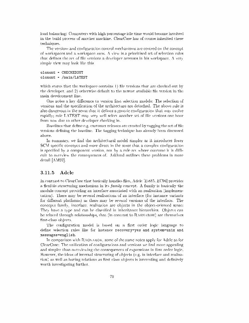
load balancing: Computers with high percentage idle time would become involved
in the build process of another machine. ClearCase has of course inherited these
techniques.
The version- and con�guration control mechanisms are centred on the concept
of workspaces and a workspace view. A view is a prioritised set of selection rules
that de�nes the set of �le versions a developer accesses in his workspace. A very
simple view may look like this
element * CHECKEDOUT
element * /main/LATEST
which states that the workspace contains 1) �le versions that are checked out by
the developer, and 2) otherwise default to the newest available �le version in the
main development line.
One notes a key di�erence to version �rst selection models: The selection of
versions and the speci�cation of the architecture are detached. The above rule is
also dangerous in the sense that it de�nes a generic con�guration that may evolve
rapidly; rule LATEST may very well select another set of �le versions one hour
from now due to other developer checking in.
Baselines that de�ne e.g. customer releases are created by tagging the set of �le
versions de�ning the baseline. The tagging technique has already been discussed
above.
In summary, we �nd the architectural model simpler as it introduces fewer
SCM speci�c concepts and more direct in the sense that a complex con�guration
is speci�ed by a component version, not by a rule set whose outcome it is diÆ-
cult to overview the consequences of. Asklund outlines these problems in more
detail [AM97].
3.11.5 Adele
In contrast to ClearCase that basically handles �les, Adele [Est85, EC94] provides
a exible structuring mechanism in its family concept. A family is basically the
module concept providing an interface associated with an realisation (implemen-
tation). There may be several realisations of an interface (for instance variants
for di�erent platforms) as there may be several versions of the interface. The
concepts family, interface, realisation are objects in the object-oriented sense:
They have a type and can be classi�ed in inheritance hierarchies. Objects can
be related through relationships, that (in contrast to Ragnarok) are themselves
�rst-class objects.
The con�guration model is based on a �rst order logic language to
de�ne selection rules like for instance recovery=yes and system=unix and
messages=english.
In comparison with Ragnarok, some of the same notes apply for Adele as for
ClearCase: The uni�cation of con�gurations and versions we �nd more appealing
and simpler than overviewing the consequences of expressions in �rst order logic.
However, the ideas of internal structuring of objects (e.g. in interface and realisa-
tion) as well as having relations as �rst class objects is interesting and de�nitely
worth investigating further.
70
3.12 Future Work
The next sections outline some of the directions in which future work is heading.
Common for most of them is their importance to scale up Ragnarok to handle
larger projects.
3.12.1 Dimensions of Versioning
Estublier argues that the individual states of a software entity, the versions, can
be classi�ed according to three dimensions based on the purpose of or process
leading to the version. These three dimensions are the historical, logical, and
cooperative dimensions [EC95]. (In another article, these dimensions are instead
named temporal, logical, and dynamic [EC94].) A main point is that these di-
mensions are orthogonal.
The historical dimension is the entity's evolution in time: We add a feature to
an existing version and create a new state in the history of the entity. The logical
dimension is another term for `variant', for instance that the same entity must
run on several platforms. Finally, the cooperative dimension are versions created
from collaborative necessity; the classical example is that by creating a branch of
the main development line, a sub-team can work independently in this branch.
This is an essential insight and important to keep it in mind. In many SCM
tools, the version graphs are instances of Tichy's version graph, where the relation
between two successive states of a software object, the `is-revision-of' relation,
simply states that y is a modi�cation of a copy of x. This does not capture the
intent of the new version: Was `y' created from `x' from evolutionary, variant
control, or cooperative necessity? The result is that the version graph serves too
many and too diverse purposes and easily evolves into a unwieldy tangle.
In our opinion, this is a problem in the COOP/Orm system (section 3.11.1)
where the version graph serves both the historical and cooperative dimension.
As it employs a product versioning technique and supports �ne grained version
control it seems that their version graph quickly will become incomprehensible
under realistic conditions.
In Ragnarok the purpose of the version graph is to capture evolution, the
historical dimension. Our view on variants has been outlined in section 3.10.5.
Version segregation should be avoided for permanent variants, and if this rec-
ommendation is followed, the logical dimension is orthogonal to the historical.
Temporary variants can be handled by branches and thus a branch in the version
graph signals temporary logical versioning.
The point that deserves further work in the architectural model, is how to
handle cooperative versions. Parallel development, exempli�ed by a parallel
development- and bug-�x development line, was outlined in section 3.5.2 and
handled by branching. It is tempting to support cooperative parallel develop-
ment using the same technique, and indeed many SCM tools do so; but this
way logical and cooperative versioning are not orthogonal: Does a branch signal
a new temporary variant or a way to facilitate cooperative work on the same
component(s)?
71
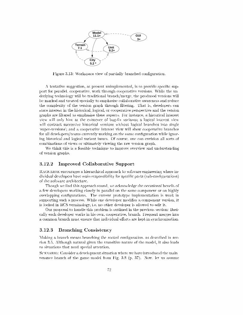
Terrain7.1
Model11.1+
Unit9.2+
City5.2 *
3+GUI
Figure 3.13: Workspace view of partially branched con�guration.
A tentative suggestion, at present unimplemented, is to provide speci�c sup-
port for parallel, cooperative, work through cooperative versions. While the un-
derlying technology will be traditional branch/merge, the produced versions will
be marked and treated specially to emphasise collaborative awareness and reduce
the complexity of the version graph through �ltering. That is, developers can
state interest in the historical, logical, or cooperative perspective and the version
graphs are �ltered to emphasise these aspects. For instance, a historical interest
view will only hint at the existence of bug-�x variants; a logical interest view
will contract successive historical versions without logical branches into single
`super-versions'; and a cooperative interest view will show cooperative branches
for all developers/teams currently working on the same con�guration while ignor-
ing historical and logical variant issues. Of course, one can envision all sorts of
combinations of views or ultimately viewing the raw version graph.
We think this is a feasible technique to improve overview and understanding
of version graphs.
3.12.2 Improved Collaborative Support
Ragnarok encourages a hierarchical approach to software engineering where in-
dividual developers have main responsibility for speci�c parts (sub-con�gurations)
of the software architecture.
Though we �nd this approach sound, we acknowledge the occasional bene�t of
a few developers working closely in parallel on the same component or on highly
overlapping con�gurations. The current prototype implementation is weak in
supporting such a process. While one developer modi�es a component version, it
is locked in RCS terminology, i.e. no other developer is allowed to edit it.
Our proposal to handle this problem is outlined in the previous section: Basi-
cally each developer works in his own, cooperative, branch. Frequent merges into
a common branch must ensure that individual e�orts are kept in synchronisation.
3.12.3 Branching Consistency
Making a branch means branching the rooted con�guration, as described in sec-
tion 3.5. Although natural given the transitive nature of the model, it also leads
to situations that need special attention.
Scenario: Consider a development situation where we have introduced the main-
tenance branch of the game model from Fig. 3.8 (p. 37). Now, let us assume
72
that these changes force us to make some changes in the GUI component, see
Fig. 3.13, which shows a workspace view of the situation: The component ver-
sions in workspace are shown as ellipses; + and * after the version identities denote
direct- and indirect modi�cations respectively. So, the �gure describes a situation
where modi�cations have been made to (Model, 11.1) and (Unit, 9.2); (City, 5.2) is
indirectly modi�ed as it depends on Unit while (Terrain, 7.1) is una�ected. Now,
we are about to make the necessary changes to the GUI component (GUI, 3).
During check-in, however, the GUI component will branch into a maintenance
branch, (GUI, 3.1), and as branching is performed transitively, we end up with
branching the Model components as well, (Model, 11.2.1), (Unit, 9.2.1), etc.
The above scenario poses no technical problems: The con�gurations are con-
sistent, no data lost, etc. The problem is that the semantics of a branch is diluted;
some branches signal deliberate decisions while others are accidental due to the
sequencing of check-ins. If we had started by branching the GUI component be-
fore branching Model, no additional branch would have resulted in the Model
components.
The scenarios is an example of premature commitment, as you have to be
foresighted and in advance decide which component to branch. In general, such
foresight cannot be assumed.
Our proposal, denoted branch uni�cation, is to keep track of the branching
structure, and in particular the branching depth of the component versions in a
con�guration, and try to keep their depths equal. In the event that this cannot
be achieved, human assistance is needed to decide which branch structure should
take precedence.
Example: In the scenario described above, the branch uni�cation algorithm
notes that all component versions in Model presently have branching depth 1
(on a branch from the main trunk) while GUI has depth 0 (on the main trunk).
Thus only the GUI component needs to be branched (to, say, (GUI, 3.1)) while
new versions can be added on the existing branches of components in Model's
con�guration.
Note that the problem is partially because Ragnarok uses the check-
in/check-out model. Models using the revise/snapshot approach (e.g.
COOP/Orm, see section 3.11.1) create a version already when `revise' is issued.
Therefore the user can manipulate the con�guration's branch structure directly.
However, we think that it is bene�cial to have similar branching structure of all
component versions in a con�guration anyway to avoid confusion.
3.12.4 Disconnected Operation
Ragnarok uses RCS as the delta-storage layer for the substance attribute (�les)
of component versions, and bene�ts from its relatively eÆcient storage model,
thoroughly tested functionality and support for binary as well as ASCII text
format. A major drawback, however, is that RCS has a inherent notion of a
centralised repository. Without direct access to the repository, RCS simply can
not do version control|and consequently, neither can Ragnarok.
In practice, developers are often interested in working without repository ac-
cess while retaining their ability to do version control. A typical case is to do
73
some work at home with only periodical (or no) access to the repository as this
requires the overhead and cost of a modem connection.
To facilitate this, two things are required: First, we need a way to make sure
that the positions within the version graph of any new version made does not
interfere with versions created by other users. Secondly, we need a way to create
and maintain new versions that does not need to consult the repository in order
to calculate deltas (di�erence to original version).
The �rst problem can be addressed by the proposal of the previous sections
namely separate cooperative versions that are maintained on special branches in
the version graph. Obviously, a developer is only allowed to work on a dedicated
branch during disconnected operation.
The second problem is divided in two subproblems: The storage of component
version information and substance version information. The �rst is already par-
tially solved in the prototype, as the implementation stores successive component
versions in separate �les. The substance version problem is best tackled by giving
up RCS as back-end. An interesting replacement is the XDelta library [Xde] that
is developed as part of the PRCS project [MH98]. XDelta is a C-library that
calculates a compact delta between two �les of any type; the delta is simply a
binary string. Thus, the evolution of the con�guration can be stored locally, as
sets of series of deltas (both component- and substance deltas), and later entered
in the central repository.
3.12.5 Softening Project Boundaries
The current Ragnarok implementation has a strong notion of a project: You
invoke both RCM and Ragnarok with a project speci�cation as argument. A
consequence is, that even though only a small sub-con�guration of the project is
relevant for developer, data for every component in the project is loaded. For large
development projects, this can become a bottleneck. Even more problematic is
the fact that the con�gurations of two di�erent projects are required to be disjoint:
That is, one project cannot reuse modules or libraries in another project. Clearly,
this is infeasible.
From the model viewpoint, it is also unnecessary. Every component version
de�nes a bound (sub)con�guration, thus every component and relation required
is known. It makes more sense that developers are allowed to specify a certain
component as argument to the prototype; then only the data relevant for the
rooted con�guration needs to be retrieved. It also makes reusing part con�gura-
tions in other projects feasible; if a dependency to a new, external, con�guration
is stated, the set of components and relations in it can be read incrementally.
3.12.6 Shared Versions
A large project is typically organised as a set of sub-projects with some internal
dependencies. Developers or teams are responsible for one or a small set of these
sub-projects and are generally not permitted (nor inclined) to modify objects in
other sub-projects.
As outlined in the previous section, Ragnarok loads data for every compo-
nent in a project; but it also copies the substance (the �les) of every component
74
into the developers local workspace (section 3.7). Potentially a vast amount of
disk space is `wasted' on identical copies of sub-projects depended upon but never
modi�ed.
Our proposal is to introduce shared versions where `shared' is in the sense
that the data of the component version is stored, read-only, in some shared,
accessible, location, and not in the local workspace. Naturally, a requirement is
that all component versions in the con�guration rooted in a shared version are
also shared. Typically, versions that are root for milestone con�gurations are
candidates for becoming shared.
This scheme leads to a substantial saving in disk-space in cases where a team
is working on software that build upon a large volume of libraries and subsystems.
For this scheme to work, Ragnarok has to be able to in uence the build pro-
cess in order to tell the compiler/linker where to look for the �les. Alternatively,
Ragnarok could introduce a virtual �le system as known from e.g. ClearCase:
All operating system calls to the �le system in the workspaces are intercepted and
for shared �le versions the calls are redirected to a shared pool of �le versions.
3.12.7 Cyclic Relations
Presently, Ragnarok does not handle cyclic relations in con�gurations. The
prototypes perform an analysis before adding new relations and if they would
result in a cycle they are rejected.
Cyclic relations pose no severe problem, however. The transitive re ective
algorithms, check-in and -out, can handle cycles by proceeding in two passes. In
the �rst pass, a cache is build of component versions in the con�guration and
in�nite recursion avoided by testing if the component about to be visited has
already been inserted in the cache. In the second pass, the actual operation is
performed on the contents of the cache.
In case of check-out, this scenario is trivial.
The check-in case is more tricky. To illustrate the problem, consider compo-
nent versions (A, 4) and (B, 12) that are cyclic dependent. If A is modi�ed and
checked in the outcome should be (A, 5) and (B, 13) with (A, 5).Srel=f(B, 13)gand (B, 13).Srel=f(A, 5)g, i.e. both version identities must be established before
the resulting component versions are stored in the repository. The tricky part
is that we cannot decide that a component version di�ers from the original in
repository (line (7) in code fragment 3.1) before the proper relation set has been
determined (loop (2))|but the transitive re exive closure includes the compo-
nent itself. In other words, we cannot determine if the component versions should
be inserted into the repository before we have actually done so. A solution is to
make all insertions �rst, then clean up the repository for component versions in-
serted but not relevant after all (no substance change and not on path to modi�ed
component version), and �nally patch up the relation sets of component versions
that was entered into the repository.
75
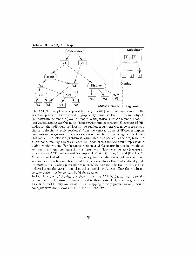
Sidebar 3.1 AND/OR Graph
V1
sin
Math
V2
DisplayV1
V2
V2
cos
Calculator
1 2
1 2
Calculator
V2V1 V1
V1 V2 V3
Display
3
AND/OR Graph Ragnarok
The AND/OR graph was proposed by Tichy [Tic82a] to explain and structure the
selection problem. In this model, graphically shown in Fig. 3.1, atomic objects
(i.e. software components) are leaf nodes, con�gurations are AND-nodes (boxes),
and version groups are OR-nodes (boxes with rounded corners). Successors of OR-
nodes are the individual versions in the version group. An OR-node represents a
choice: Selecting speci�c version(s) from the version group; AND-nodes implies
composition/integration: Successors are combined to form a con�guration. Given
this model, the selection problem is formulated as a search in the graph from a
given node, making choices at each OR-node such that the result represents a
viable con�guration. For instance, version 2 of Calculator in the �gure above,
represents a bound con�guration (or baseline in Tichy terminology) because all
arcs connect AND nodes|and is composed of (sin, 2), (cos, 2), and (Display, 3).
Version 1 of Calculator, in contrast, is a generic con�guration where the actual
version selection has not been made, i.e. it only states that Calculator depends
on Math but not what particular version of it. Version selection in this case is
deferred from the version model to other models/tools that allow the resolution
to take place in order to, say, build the system.
In the right part of the �gure is shown, how the AND/OR graph can partially
be mapped to the visual formalism used in this thesis. Only version groups for
Calculator and Display are shown. The mapping is only partial as only bound
con�gurations are relevant in a Ragnarok context.
76
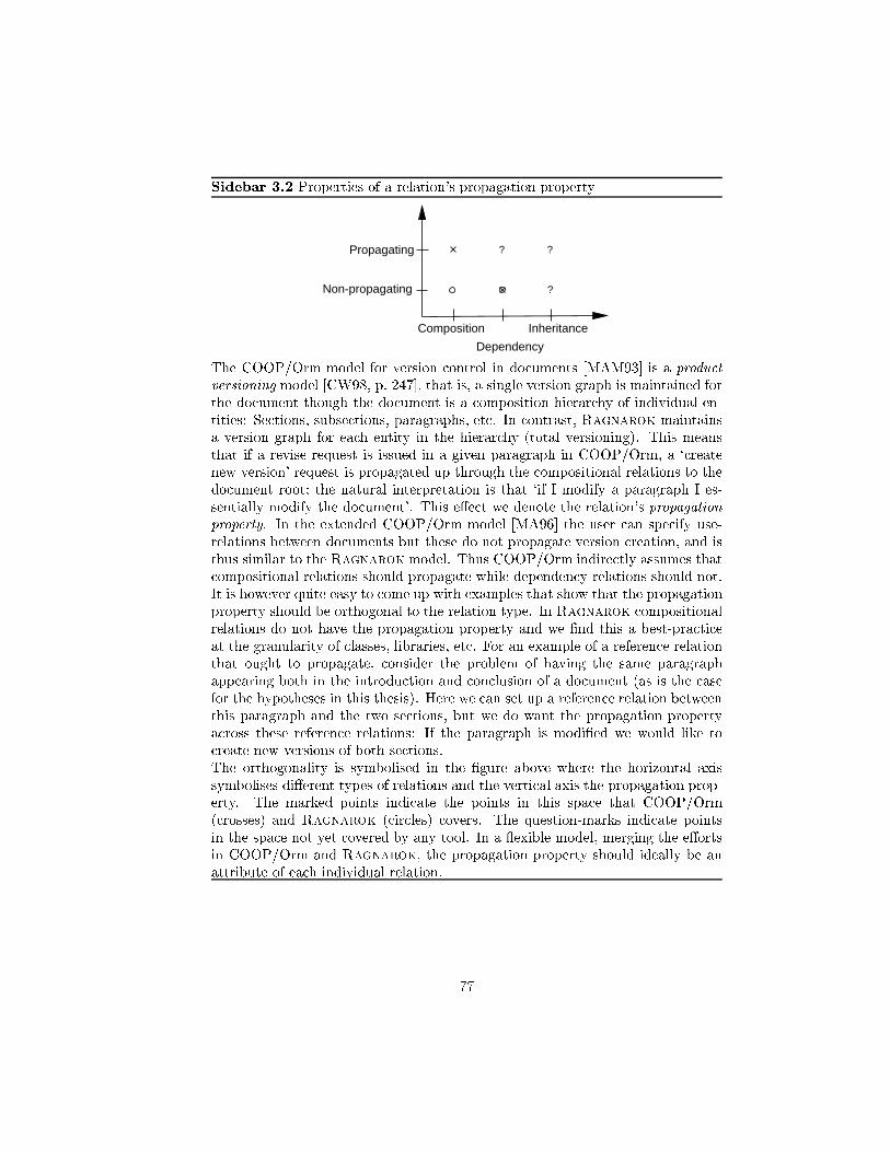
Sidebar 3.2 Properties of a relation's propagation property
Non-propagating
Propagating
Composition Inheritance
Dependency
? ?
?
The COOP/Orm model for version control in documents [MAM93] is a product
versioning model [CW98, p. 247], that is, a single version graph is maintained for
the document though the document is a composition hierarchy of individual en-
tities: Sections, subsections, paragraphs, etc. In contrast, Ragnarok maintains
a version graph for each entity in the hierarchy (total versioning). This means
that if a revise request is issued in a given paragraph in COOP/Orm, a `create
new version' request is propagated up through the compositional relations to the
document root; the natural interpretation is that `if I modify a paragraph I es-
sentially modify the document'. This e�ect we denote the relation's propagation
property. In the extended COOP/Orm model [MA96] the user can specify use-
relations between documents but these do not propagate version creation, and is
thus similar to the Ragnarok model. Thus COOP/Orm indirectly assumes that
compositional relations should propagate while dependency relations should not.
It is however quite easy to come up with examples that show that the propagation
property should be orthogonal to the relation type. In Ragnarok compositional
relations do not have the propagation property and we �nd this a best-practice
at the granularity of classes, libraries, etc. For an example of a reference relation
that ought to propagate, consider the problem of having the same paragraph
appearing both in the introduction and conclusion of a document (as is the case
for the hypotheses in this thesis). Here we can set up a reference relation between
this paragraph and the two sections, but we do want the propagation property
across these reference relations: If the paragraph is modi�ed we would like to
create new versions of both sections.
The orthogonality is symbolised in the �gure above where the horizontal axis
symbolises di�erent types of relations and the vertical axis the propagation prop-
erty. The marked points indicate the points in this space that COOP/Orm
(crosses) and Ragnarok (circles) covers. The question-marks indicate points
in the space not yet covered by any tool. In a exible model, merging the e�orts
in COOP/Orm and Ragnarok, the propagation property should ideally be an
attribute of each individual relation.
77

78
Chapter 4
Geographic Space
Architecture Visualisation
For the architecture to be e�ective as the backbone of the project's
design, it must be communicated clearly and unambiguously to
all of the stake-holders who have an interest in it. Develop-
ers must understand the work assignments it requires of them,
testers must understand the task structure it imposes on them,
management must understand the scheduling implications it sug-
gests, etc. Towards this end, the representation medium should
be informative, unambiguous, and readable by many people with
varied backgrounds.Bass, Clements, and Kazman, Software Architecture in Practice, p. 16
The meaning of visualisation is `the formation of a mental image.' With the
introduction of powerful, graphical, workstations a new type of computational
driven systems arose that, in contrast to the old textual systems, more directly
could help forming this `mental image'.
Today, graphical visualisation systems are used for a vast number of purposes:
computer aided design, multimedia, cartoon animation, simulation of physical
and chemical processes, algorithm visualisation, ight simulators, and not least
entertainment, where high resolution, real-time, 3D graphics games are among
the applications that de�ne the requirements on standard PC hardware. A wide
range of visualisations is presented by Tufte [Tuf90].
79
Within the �eld of software engineering, visualisation systems have also re-
ceived attention. One of the most basic types of visualisation is pretty printing
code where font faces and colour highlight keywords and syntactical constructs
(e.g. in Emacs [Sta84], Desert [Rei96], and commercial environments from Bor-
land and Microsoft). Dynamic behaviour can be visualised through animation of
data-structures to illustrate algorithm executions. Another type of dynamics is
shown by tools that visualise e.g. call-graphs for particular executions. Finally
software structure can be visualised as class inheritance graphs extracted from
source code, etc. A thorough 3D software engineering visualisation framework is
presented by Reiss [Rei95b]; and of course there is the plethora of modelling nota-
tions and supporting tools that show software design [Boo91, RBP+91, BRJ97],
use case scenarios [JCJ�O92], event traces, etc. using various visual layouts, often
adopting graphs as visual formalism [Har88].
This chapter is devoted to the visual model that Ragnarok employs to vi-
sualise the logical software architecture of a project. Parts of this work has been
published in the papers [Chr97a, Chr98g]. A user guide and manual for the Rag-
narok prototype's visual presentation layer is available on-line [Chr98b] from the
Ragnarok homepage http://daimi.au.dk/~hbc/Ragnarok.html.
4.1 Motivation
A key problem that has motivated the visual model for the Ragnarok user in-
terface, is the complexity and sheer amount of data produced in the development
process of large software projects; as systems grow ever larger it becomes increas-
ingly diÆcult to maintain overview and navigate in the many aspects and data
of the system. This, in turn, implies problems of e�ective communication within
the team on the system's development.
{ By overview, we mean the ability to identify the major components of the
software system; understand what purpose they have for achieving the over-
all goal; and understand how these relate to each other and cooperate in
achieving the common goal.
{ By navigation, we mean the ability to locate needed components and frag-
ments of data quickly and with as little e�ort as possible.
{ By communication, we mean that the team share a common understanding
and vocabulary concerning the overall structure, tasks and goals of the
software project.
We think one of the possible causes of diÆculty in overview, navigation, and
communication, was pointed out clearly by Brooks in his famous article `No Sil-
ver Bullet|Essence and Accidents of Software Engineering' where Brooks states
invisibility as an inherent, not accidental, property of software [Fre87]: The multi-
dimensional nature of software does not easily lend itself to a single 2D or 3D
diagrammatic form and thereby deprives us one of our most powerful conceptual
tools: Our visual and spatial perception.
80

We think, however, that many interesting dimensions of software and data
from the development process can still be visualised bene�cially using a single
metaphor: A geographic space metaphor [KB96], which forms the conceptual
basis for the user interface of Ragnarok|the topic of this chapter.
4.2 Human Navigation and Spatial Metaphors
McKnight et al. describe a psychological theory about human navigation, �rst
proposed by Tolman in 1948 [MDR91]. According to this theory, humans build
a cognitive map that is analogue to the physical layout of the environment. The
acquisition of navigation knowledge to form such a map proceeds through several
stages: landmark-, route-, and survey-knowledge.
First, geographical knowledge is represented in terms of highly salient visual
landmarks in the environment such as remarkable buildings, statues, trees, etc.
We recognise our position relative to such landmarks and learn the relative posi-
tions of the landmarks. Next stage is when we can plan a route from one location
to another using knowledge of the landmarks that must be passed during the
move; but the route chosen may be non-optimal. Finally, survey knowledge is
the fully developed cognitive map that allows optimal routes to be planned and
accurate positions described.
Underlining all stages are two important properties of our perception of phys-
ical environments: The existence of salient landmarks and their positional sta-
bility. Humans are apt at navigating in a well-known physical environment: As
Kuhn and Blumenthal notes: `Perception, manipulation, and motion in space
are largely subconscious activities that impose little cognitive load while o�ering
powerful functionality' [KB96].
Spatial reasoning, spatial memory, and our sense of locality are fundamental
aspects of our perception and permeate everything we do. Even our language is
full of terms modelled over space: `the argument goes around in circles', `we set
out to prove', `a central role', `building on experience', `on top of that', `we will
go as far as to state', etc.
In the context of spatial metaphors [KB96, EM95], a distinction is made be-
tween desktop- (small scale) and geographic (large scale) spaces. The distinction
comes from everyday experience: Objects in a desktop space have sizes compa-
rable to the human body and can readily be moved and turned, whereas objects
in geographic space are beyond the human body and have �xed positions over a
long time-scale, like for instance buildings, trees, streets, and so forth.
Of the two properties mentioned above, salience and positional stability, only
geographic space may claim the latter. In a desktop space, objects are easily,
and consequently often, moved around making it next to impossible to build the
cognitive map, that Tolman speaks of. In geographic space, objects have stable
positions, and the perception of them `triggers the eye and mind' giving almost
instant knowledge of position and direction to a target location, once suÆcient
route- or survey knowledge has been acquired.
81
4.3 Proposal
The vision in Ragnarok is to manage essential aspects of the development pro-
cess with minimal overhead, and the main hypothesis is that the logical software
architecture is a sound framework to achieve this goal. The hypothesis forwarded
in the speci�c context of project overview, navigation, and communication is:
The logical software architecture should be visually manifest in a ge-
ographical organised `software landscape'. This software landscape
should be the focal point of the development environment by being
shared in the team and by mediating daily activities.
The geographic space architecture visualisation model proposes to represent the
abstractions of a software design by visual landmarks having stable positions,
sizes, and appearances in a plane thereby creating a manifest `design landscape'.
Landmarks are directly manipulable and mediate daily development tasks: Source
fragments are accessed, defect reports added, sta� hours logged, libraries com-
piled, identi�ers searched for, and so forth, through landmarks. The landscape
is shared in the sense that project team members view and manipulate the same
landscape. Di�erent dimensions (aspects) of the design entities like e.g. the source
code �les implementing it, documentation, staÆng- and budget information, pro-
�ling information, version- and con�guration control, etc., are visualised by pro-
cessing the associated data appropriately and control the visual appearance of
landmarks based on this processing; in the same way as ordinary maps may show
di�erent aspects like vegetation, roads, elevation, or population density, of the
same region of a country.
The underlying idea is to employ humans �ne spatial and visual perception
and memory to enhance and ease the process of navigation and aid in forming a
common understanding of the software architecture.
Speci�cally, the proposed visual model aims at addressing the following topics:
1. Overview and navigation
2. Mediating, up-to-date, software design
3. Communication and collaboration
4. Visualisation framework
Ad. 1: Overviewing large software systems and �nding the correct piece of code
in the thousands of �les and libraries, is becoming a daunting task even in sys-
tems with a sound logical design. Explaining the design to newcomers is also
problematic [BGZ95].
Ad. 2: The majority of software systems are still implemented in terms of source
code �les|and �les does not convey much information about the design of a
software system. Architectural documentation must thus rely on some set of ex-
ternally maintained documents. These are often simply non-existing, out of sync
with the actual implementation, or the correlation to actual code is unclear [KC99,
p. 1].
82
Ad. 3: Software development is a team e�ort today. Therefore a common un-
derstanding and reference frame is essential to allow the software design to be
discussed, documented, and reused.
Having an explicit and well-communicated architecture is the �rst step
towards ensuring architectural conformance.[BCK98]
Ad. 4: Data in a software project is inherently multi-dimensional: One dimen-
sion is the source �les; another the budgets, task-lists, and staÆng information;
yet another version control, etc. Traditionally these di�erent dimensions are han-
dled by di�erent tools and organisational procedures and summary information
presented in di�erent formats: Lists, tables, graphs, etc.
4.4 Visualisation Model
In this section the basic concepts in the Ragnarok visual model will be pre-
sented.
4.4.1 Landscape, Landmark, and Decoration
The landscape is an in�nite two dimensional plane. The landscape serves as a
space for geographically organising landmarks and decorations.
A landmark occupies a well de�ned region of the landscape and represents
a software component1 and hence an abstraction in the software design. In the
present Ragnarok implementation, a landmark is (unimaginatively) represented
by a rectangular region. (We have chosen the term `landmark' both to underline
the reference to real geographical space as well as to distinguish the visual element
from the underlying data-carrying component.)
Compositional relations (part/whole) between components are visualised by
spatial containment i.e. the landmarks associated with components that are part
of a component A are positioned inside the landmark of A. In Fig. 4.1 a legal
landscape for the design structure in Fig. 2.3 (p. 15) is shown.
Thus, the software landscape will represent the architecture of our software
system as a geographically organised, hierarchically nested, set of regions, each
region representing an abstraction in the architecture. Spatial containment is
a natural paradigm for representing composition, established from everyday ex-
perience (the objects are inside the container). In our context, the context of
software architecture and logical design, the level of containment maps well to
the notion of level of abstraction. We may discuss a software design at a high
level of abstraction, say in terms of a set of subsystems, or at a detailed level, say
in terms of individual classes. In the visualisation model we may similarly choose
to limit the level of view to a given level of abstraction, for instance only dis-
play the Model landmark but not the classes inside, to support such discussions.
(Figure 4.3 shows an example of this.)
1More correctly: a software component version (section 2 and 3).
83
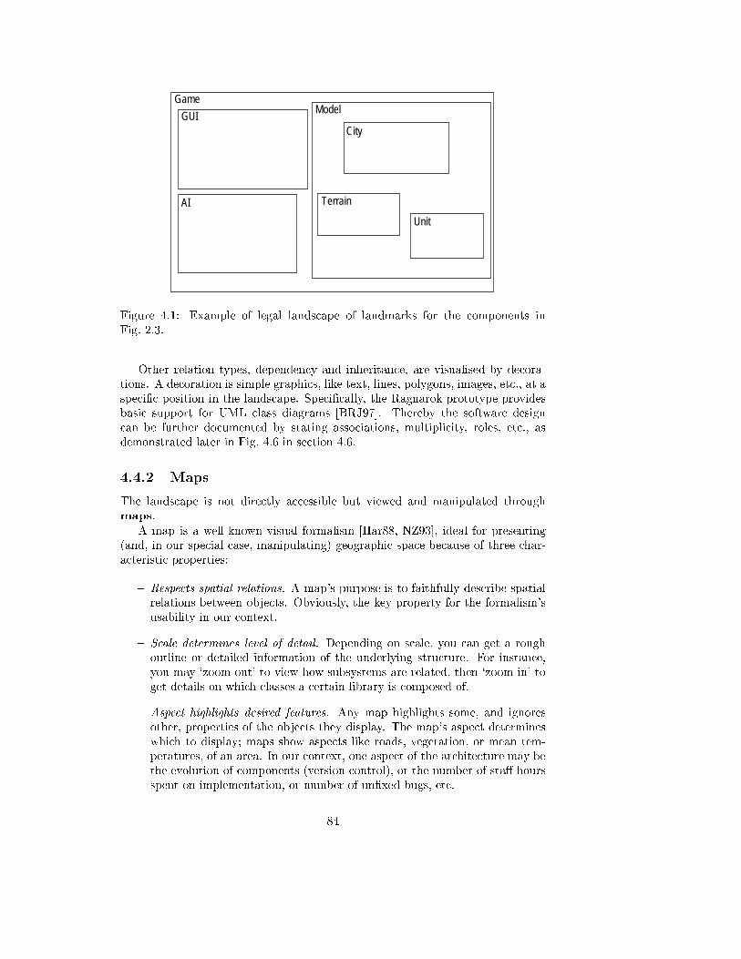
Game
GUIModel
AI
City
Terrain
Unit
Figure 4.1: Example of legal landscape of landmarks for the components in
Fig. 2.3.
Other relation types, dependency and inheritance, are visualised by decora-
tions. A decoration is simple graphics, like text, lines, polygons, images, etc., at a
speci�c position in the landscape. Speci�cally, the Ragnarok prototype provides
basic support for UML class diagrams [BRJ97]. Thereby the software design
can be further documented by stating associations, multiplicity, roles, etc., as
demonstrated later in Fig. 4.6 in section 4.6.
4.4.2 Maps
The landscape is not directly accessible but viewed and manipulated through
maps.
A map is a well-known visual formalism [Har88, NZ93], ideal for presenting
(and, in our special case, manipulating) geographic space because of three char-
acteristic properties:
{ Respects spatial relations. A map's purpose is to faithfully describe spatial
relations between objects. Obviously, the key property for the formalism's
usability in our context.
{ Scale determines level of detail. Depending on scale, you can get a rough
outline or detailed information of the underlying structure. For instance,
you may `zoom out' to view how subsystems are related, then `zoom in' to
get details on which classes a certain library is composed of.
{ Aspect highlights desired features. Any map highlights some, and ignores
other, properties of the objects they display. The map's aspect determines
which to display; maps show aspects like roads, vegetation, or mean tem-
peratures, of an area. In our context, one aspect of the architecture may be
the evolution of components (version control), or the number of sta� hours
spent on implementation, or number of un�xed bugs, etc.
84
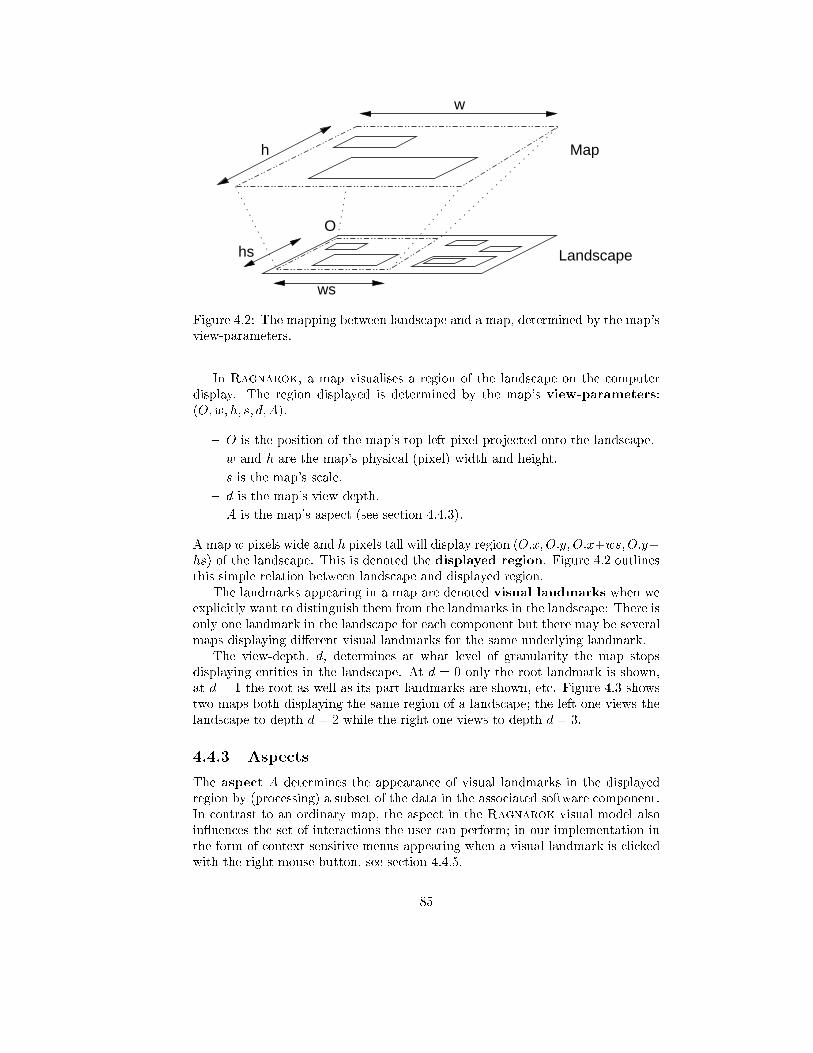
w
O
ws
hs
h Map
Landscape
Figure 4.2: The mapping between landscape and a map, determined by the map's
view-parameters.
In Ragnarok, a map visualises a region of the landscape on the computer
display. The region displayed is determined by the map's view-parameters:
(O;w; h; s; d; A).
{ O is the position of the map's top left pixel projected onto the landscape.
{ w and h are the map's physical (pixel) width and height.
{ s is the map's scale.
{ d is the map's view-depth.
{ A is the map's aspect (see section 4.4.3).
A map w pixels wide and h pixels tall will display region (O:x;O:y;O:x+ws;O:y+
hs) of the landscape. This is denoted the displayed region. Figure 4.2 outlines
this simple relation between landscape and displayed region.
The landmarks appearing in a map are denoted visual landmarks when we
explicitly want to distinguish them from the landmarks in the landscape: There is
only one landmark in the landscape for each component but there may be several
maps displaying di�erent visual landmarks for the same underlying landmark.
The view-depth, d, determines at what level of granularity the map stops
displaying entities in the landscape. At d = 0 only the root landmark is shown,
at d = 1 the root as well as its part landmarks are shown, etc. Figure 4.3 shows
two maps both displaying the same region of a landscape; the left one views the
landscape to depth d = 2 while the right one views to depth d = 3.
4.4.3 Aspects
The aspect A determines the appearance of visual landmarks in the displayed
region by (processing) a subset of the data in the associated software component.
In contrast to an ordinary map, the aspect in the Ragnarok visual model also
in uences the set of interactions the user can perform; in our implementation in
the form of context-sensitive menus appearing when a visual landmark is clicked
with the right mouse button, see section 4.4.5.
85
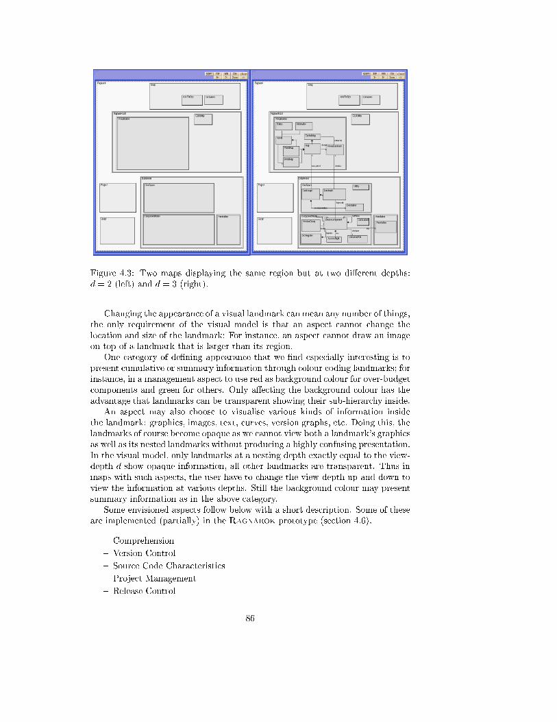
Figure 4.3: Two maps displaying the same region but at two di�erent depths:
d = 2 (left) and d = 3 (right).
Changing the appearance of a visual landmark can mean any number of things,
the only requirement of the visual model is that an aspect cannot change the
location and size of the landmark: For instance, an aspect cannot draw an image
on top of a landmark that is larger than its region.
One category of de�ning appearance that we �nd especially interesting is to
present cumulative or summary information through colour coding landmarks; for
instance, in a management aspect to use red as background colour for over-budget
components and green for others. Only a�ecting the background colour has the
advantage that landmarks can be transparent showing their sub-hierarchy inside.
An aspect may also choose to visualise various kinds of information inside
the landmark: graphics, images, text, curves, version graphs, etc. Doing this, the
landmarks of course become opaque as we cannot view both a landmark's graphics
as well as its nested landmarks without producing a highly confusing presentation.
In the visual model, only landmarks at a nesting depth exactly equal to the view-
depth d show opaque information, all other landmarks are transparent. Thus in
maps with such aspects, the user have to change the view-depth up and down to
view the information at various depths. Still the background colour may present
summary information as in the above category.
Some envisioned aspects follow below with a short description. Some of these
are implemented (partially) in the Ragnarok prototype (section 4.6).
{ Comprehension
{ Version Control
{ Source Code Characteristics
{ Project Management
{ Release Control
86
Ad. Comprehension: The processing suggested in what we term `Comprehen-
sion aspect' is simply no processing. The purpose of the aspect is to focus on
documenting the architecture itself. A gray scale is used in Ragnarok for land-
mark colours, indicating the depth of the landmark. Pop-up menu entries on
landmarks give access to textual or HTML based documentation for the individ-
ual components.
Ad. Version Control: Coding landmark colours according to the state of com-
ponents in the developer's workspace compared to the repository state, for in-
stance show that newer versions of a library exists than presently used by the
developer (see section 4.6.3). Landmarks mediate version control actions like
check-out, check-in, etc. Landmarks could also display the version graph with
the currently checked-out version highlighted.
Ad. Source Code Characteristics: Inspired by work by Baker, Eick, and
Ball [BE96, BE95] the interior of landmarks could display source code charac-
teristics in compact form. Examples from the articles include code age, software
complexity, execution hot spots, number of changes, etc.
Ad. Project Management: Management annotation data of a component may
be processed to yield a colour code for estimated-time-to-complete, ranging from
green (on schedule) to red (delayed), for landmark background colours. Simi-
larly, the colours could signal actual-versus-budget-costs, risk estimates, �tness
factor (Goldberg and Rubin [GR95, chap. 7] give a comprehensive list of man-
agement attributes). The landmarks could mediate access to budgets, plans, task
descriptions, staÆng, etc. This aspect should support synthesised annotations
(section 2.2.2), for instance the amount of development time spent on a compo-
nent is the sum of hour spent directly on it added to the time spent recursively
on its part components.
Ad. Release Control: Release control should be supported by annotations on
component that list test-suits to be run and possibly check-lists of items to try
manually (typically to verify user interface issues that are diÆcult to test by
scripts). A release control aspect map must highlight components where there
are unchecked items on the checklist and test-suits that have not been run. Land-
marks should mediate changes to test-suits and checklists.
4.4.4 Correlation to Architecture
The visualisation consists of three layers. The fundamental layer is the archi-
tectural description of design in terms of components and their relations; this is
the architectural layer. The second layer is the software landscape that de�nes a
2D plane and associates landmarks with components, under the constraint that
part landmarks are positioned inside their `parent' landmark; this is the landscape
layer. The third layer is the maps that display selected parts of the landscape and
through the map's aspect emphasise certain data of the underlying component;
this is the map layer. This layered structure is depicted in Fig. 4.4.
4.4.5 Interaction and Mediation
The interaction model employed is direct manipulation [Shn83, HHN86].
87
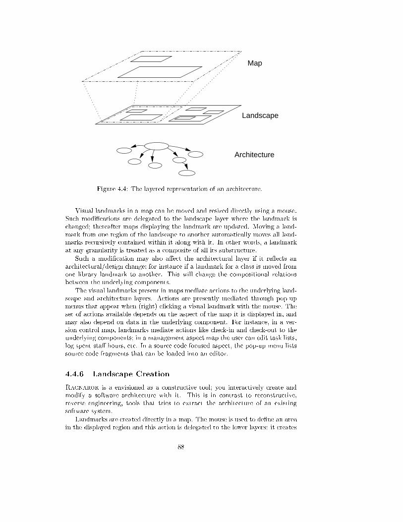
Map
Landscape
Architecture
Figure 4.4: The layered representation of an architecture.
Visual landmarks in a map can be moved and resized directly using a mouse.
Such modi�cations are delegated to the landscape layer where the landmark is
changed; thereafter maps displaying the landmark are updated. Moving a land-
mark from one region of the landscape to another automatically moves all land-
marks recursively contained within it along with it. In other words, a landmark
at any granularity is treated as a composite of all its substructure.
Such a modi�cation may also a�ect the architectural layer if it re ects an
architectural/design change; for instance if a landmark for a class is moved from
one library landmark to another. This will change the compositional relations
between the underlying components.
The visual landmarks present in maps mediate actions to the underlying land-
scape and architecture layers. Actions are presently mediated through pop-up
menus that appear when (right) clicking a visual landmark with the mouse. The
set of actions available depends on the aspect of the map it is displayed in, and
may also depend on data in the underlying component. For instance, in a ver-
sion control map, landmarks mediate actions like check-in and check-out to the
underlying components; in a management aspect map the user can edit task lists,
log spent sta� hours, etc. In a source code focused aspect, the pop-up menu lists
source code fragments that can be loaded into an editor.
4.4.6 Landscape Creation
Ragnarok is a envisioned as a constructive tool; you interactively create and
modify a software architecture with it. This is in contrast to reconstructive,
reverse engineering, tools that tries to extract the architecture of an existing
software system.
Landmarks are created directly in a map. The mouse is used to de�ne an area
in the displayed region and this action is delegated to the lower layers: it creates
88
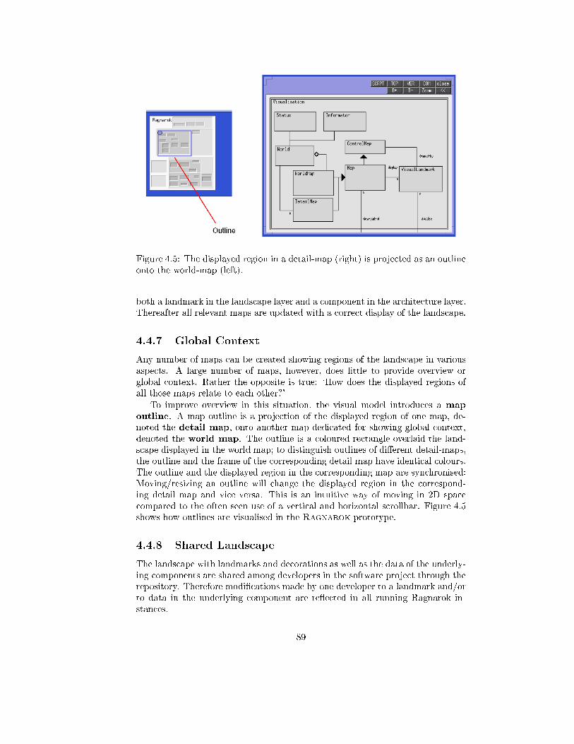
Figure 4.5: The displayed region in a detail-map (right) is projected as an outline
onto the world-map (left).
both a landmark in the landscape layer and a component in the architecture layer.
Thereafter all relevant maps are updated with a correct display of the landscape.
4.4.7 Global Context
Any number of maps can be created showing regions of the landscape in various
aspects. A large number of maps, however, does little to provide overview or
global context. Rather the opposite is true: `How does the displayed regions of
all those maps relate to each other?'
To improve overview in this situation, the visual model introduces a map
outline. A map outline is a projection of the displayed region of one map, de-
noted the detail map, onto another map dedicated for showing global context,
denoted the world map. The outline is a coloured rectangle overlaid the land-
scape displayed in the world map; to distinguish outlines of di�erent detail-maps,
the outline and the frame of the corresponding detail map have identical colours.
The outline and the displayed region in the corresponding map are synchronised:
Moving/resizing an outline will change the displayed region in the correspond-
ing detail map and vice versa. This is an intuitive way of moving in 2D space
compared to the often seen use of a vertical and horizontal scrollbar. Figure 4.5
shows how outlines are visualised in the Ragnarok prototype.
4.4.8 Shared Landscape
The landscape with landmarks and decorations as well as the data of the underly-
ing components are shared among developers in the software project through the
repository. Therefore modi�cations made by one developer to a landmark and/or
to data in the underlying component are re ected in all running Ragnarok in-
stances.
89
4.5 Model Properties
This section outlines major properties of the proposed visual model and argues
how these properties can and will be used to address the problems outlined in
section 4.3.
4.5.1 Geographical Organisation
Navigation in traditional systems is name-based: You must remember a sequence
of directory names and a �lename to access data. The landscape metaphor allows
architectural entities to be assigned a unique position. Thereby, emphasis is
shifted from name-based to location-based search: Developers get to known where
a given set of data is located. In short, humans spatial memory and abilities can
be exploited in search situations.
The geographical organisation allows us to make use of our well developed and
precise spatial vocabulary in communicating ideas, instructions, and information
relevant to the architecture. As an example, newcomers can be guided to relevant
parts using simple instructions: `eastern part', `further to the left', etc., and can
report locations in a similar way.
A company can develop positional semantics, e.g. a set of guidelines for ge-
ographical organisation of recurring architectural patterns. For instance, it is
common in computer science textbooks to display a layered architecture with
the basic (hardware near) layers at the bottom and the more advanced at the
top. Such guidelines can be formulated in terms of positional relations: `IO and
database related libraries at the bottom', `User interface components at the top',
`Business rule related components in the centre', etc. (Indeed, the landscape for
Ragnarok follows the `more elaborate components towards the top' convention
though this decision was not made consciously.)
At a more subtle level, position of components may also carry valuable infor-
mation. For instance, in a class-category or library, there may be a single class
that de�nes core functionality, aided by a number of helper classes. We think such
core components are likely positioned centrally within the region de�ned by the
library component. Being at the centre is a direct, visual, way of signalling that
the class is indeed central. The core class will have relations to all helper classes
but these should be weakly related to adhere to standard software engineering
doctrine, so positioning the class centrally will also make a nicer visual layout
with fewer crossing lines of relations. (An example is present in the Ragnarok
architecture in Fig. 3.11.) The size of a landmark may provide information as well.
The size of a component can bene�cially be used to signal relative importance in
a given context.
It should be noted that we do not see location-based navigation as superior
to name-based search in all respects; rather they complement each other well
and serve di�erent purposes. Name-based organisation has advantages when hu-
mans must process lots of new data in a short time, as shown by Jones and
Dumas [JD86]; and for seldom accessed entities it may also be easier to remem-
ber a name than a location. Location-based navigation has its main advantage
90
when it comes to locating core entities that are accessed all the time; just as
navigation is easy in your hometown, but diÆcult in an unknown city.
4.5.2 Hierarchical Presentation
Landmarks are generally transparent in the sense that part landmarks are visible
inside. This is a compact visualisation of an architecture's hierarchy, typically
components to a depth of 3{4 levels in the hierarchy are visible at the same time.
Compare this to single level visibility of directory structure in a shell, or the single
path visibility in Windows Explorer.
The compact presentation combined with stability of the landmarks' positions
is a factor in achieving overview. Spatial containment is a direct and strong visible
indication of the cohesion of a set of component; for instance a set of collaborating
classes that form a library. The broad-brush visual impression of the landscape
is able to stay intact in most cases, even when new landmarks are created or a
small number of existing ones rearranged, typically the evolution of an mature
architecture will see many more changes at a �ne granularity than at a coarse
one. Important subsystem or library landmarks are less likely to move than, say,
individual classes within a library.
4.5.3 Decoration
Decorations are a simple way to add coarse-grained documentation directly to
the landscape. Using for instance OMT or UML class diagram notation, or a
company de�ned variant hereof, the landscape can become the reference docu-
mentation of the system's static and logical design within the project. In contrast
to diagrams made in separate CASE tools or drawing applications, we think there
will be a higher pressure on team members to ensure that the decorated landscape
re ects the `true' architecture. First of all because all team members: managers,
testers, coders, maintainers, etc., are confronted with the landscape daily and
consequently errors cannot go unnoticed as easily as a diagram in a binder on a
shelf. Secondly, it may be easier to make yourself �x the error as you are already
within the environment.
4.5.4 Map Layer
Users interact with the software landscape through maps. While complicating the
visual model somewhat, it a�ords juxtaposability (section 4.9.1), i.e. the ability to
present physically distant areas in detail on the display at the same time. One
simply creates two maps, one for each area. Similarly, one may view the same
region of the landscape through two maps, each showing di�erent aspects, for
easy comparison. Or one map can be used for a coarse overview while another
shows detail.
4.5.5 Mediation
The landscape plays an active role in everyday development as landmarks mediate
often occurring tasks and in return visualises the outcome of performing these
91
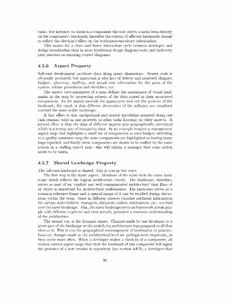
tasks. For instance, to check-in a component the user selects a menu item directly
on the component's landmark; hereafter the colours of a�ected landmarks change
to re ect the check-in's e�ect on the workspace-repository relationship.
This makes for a close and faster interaction cycle between developer and
design visualisation than in more traditional design diagram tools; and indirectly
puts pressure on ensuring correct diagrams.
4.5.6 Aspect Property
Software development produces data along many dimensions. Source code is
obviously produced; but important is also lists of defects and proposed changes;
budget-, planning-, staÆng-, and actual cost information for the parts of the
system; release procedures and checklists; etc.
The aspect view-parameter of a map de�nes the appearance of visual land-
marks in the map by processing subsets of the data stored in their associated
components. As the aspect controls the appearance and not the position of the
landmark, the result is that di�erent dimensions of the software are visualised
overlaid the same stable landscape.
A �rst e�ect is that navigational and spatial knowledge acquired doing one
task remains valid as one proceeds to other tasks focusing on other aspects. A
second e�ect is that the data of di�erent aspects gets geographically correlated
which is a strong way of comparing data. As an example imagine a management
aspect map that highlights a small set of components as over budget; switching
to a quality assurance map the same components are highlighted as having many
bugs reported; and �nally these components are shown to be sta�ed by the same
person in a staÆng aspect map|this will inform a manager that some action
needs to be taken.
4.5.7 Shared Landscape Property
The software landscape is shared. This is true in two ways.
The �rst way is the static aspect. Members of the team view the same land-
scape which re ects the logical architecture closely. The landscape, therefore,
serves as part of an `explicit and well-communicated architecture' that Bass et
al. stress as important for architectural conformance. The landscape serves as a
common reference frame and a mental image of it can be recalled during discus-
sions within the team. Maps in di�erent aspects visualise pertinent information
for various stake-holders: managers, designers, coders, maintainers, etc., overlaid
over the same landscape. Alas, the same landscape serve as framework across peo-
ple with di�erent expertise and thus actively promotes a common understanding
of the architecture.
The second way is the dynamic aspect. Changes made by one developer to a
given part of the landscape or the underlying architecture is propagated to all that
observe it. This is true for geographical rearrangement of landmarks; in practice,
however, changes made at the architectural level are perhaps more important, as
they occur more often. When a developer makes a check-in of a component, all
version control aspect maps that view the landmark of this component will signal
the presence of a new version in repository (see section 4.6.3); a developer that
92
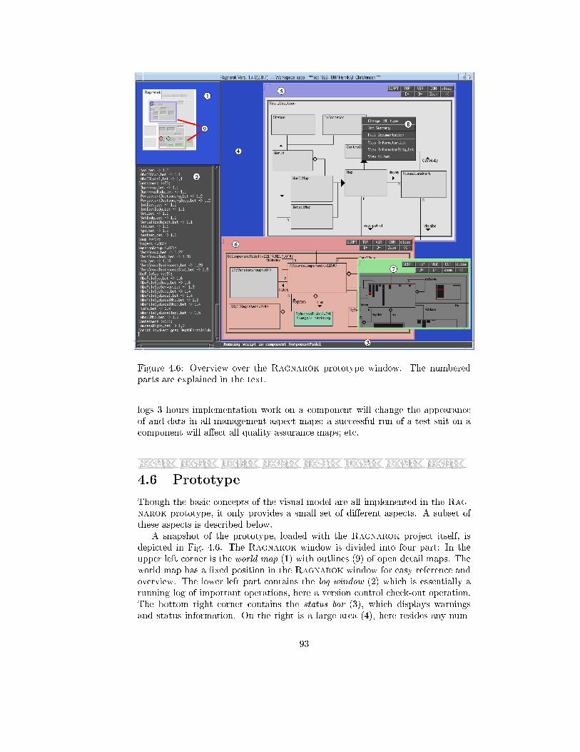
Figure 4.6: Overview over the Ragnarok prototype window. The numbered
parts are explained in the text.
logs 3 hours implementation work on a component will change the appearance
of and data in all management aspect maps; a successful run of a test-suit on a
component will a�ect all quality assurance maps; etc.
4.6 Prototype
Though the basic concepts of the visual model are all implemented in the Rag-
narok prototype, it only provides a small set of di�erent aspects. A subset of
these aspects is described below.
A snapshot of the prototype, loaded with the Ragnarok project itself, is
depicted in Fig. 4.6. The Ragnarok window is divided into four part: In the
upper left corner is the world map (1) with outlines (9) of open detail maps. The
world map has a �xed position in the Ragnarok window for easy reference and
overview. The lower left part contains the log window (2) which is essentially a
running log of important operations, here a version control check-out operation.
The bottom right corner contains the status bar (3), which displays warnings
and status information. On the right is a large area (4), here resides any num-
93
ber of detail maps (5{7). Each detail map has its own frame colour identical to
the colour of the corresponding outline in the world map. Visual landmarks are
generally displayed as simple, coloured, rectangles containing component name
and possible additional information. Clicking any visual landmark brings up a
context-sensitive menu which lists available actions on the underlying compo-
nent (8).
4.6.1 Comprehension
The focus is documenting the static/logical structure of the software architecture
through a modelling notation, here UML class diagram notation. The aspect does
not do any complex processing, landmark colours are gray levels according to the
depth of the component within the architecture. Landmark frames are also UML
class diagram inspired: Single frame indicate class, double frame a class-category,
and frame with shadow a class utility. The detail-map number (5) in Fig. 4.6
shows the Visualisation class-category of the Ragnarok implementation: You
can readily identify the classes that implement the concepts of the visualisation
model: Map, visual landmark, world- and detail-map. Decorations show relations,
inheritance, roles, and multiplicity: World is an aggregate of a single world-map
and associated to 0..n detail-maps; both inherit from superclass Map; a Map
visualises 0..n visual landmarks; and so forth.
The mediating actions available from this aspect are access to further doc-
umentation: Summary as well as detailed information, see the pop-up menu of
map (5) in Fig. 4.6. Also this aspect provides access to the underlying source code
fragments. For instance, the action taken if menu item View Informator.bet is
chosen is to instruct the editor to load this �le. (The actual loading process is
done by a Tcl script which Ragnarok provides with the �lename as parameter;
this way loading can be tailored for given operating systems and editors.)
This aspect, though simple, illustrate an important point namely that the
UML class diagrams of a system play an up-front role as mediator of daily activ-
ities instead of being passive documents. If you were a newcomer, supposed to
enhance parts of Ragnarok, the overall design would be shown and explained
to you within the daily development environment|and you would do your work
through the visual design.
4.6.2 Topography
This aspect visualises the topography of the architecture, trying to minimise
the amount of information. This provides a compact overview, refer to the world
map (1) in Fig. 4.6. Decorations are not shown, and landmarks are grayed accord-
ing to their depths and without text. The context-sensitive menu lists (source)
�les in the component and choosing one loads the �le into an editor.
This aspect is the standard one for the world map providing convenient
overview of the project landscape and a neutral background for outlines. A strong
property of the topography aspect world map is that in essence it is a compact
and fast �le browser: Any of the 160 source �les in the Ragnarok project can
be loaded into our emacs editor using one mouse-click in the world map (clicking
the landmark brings up a pop-up menu listing all �les in the substance of the
94
Figure 4.7: A map showing the version control aspect.
underlying component, releasing the mouse button over the wanted �le tells our
editor to load it).
4.6.3 Version Control
Naturally, there is an aspect to visualise properties of the underlying architectural
software con�guration management system in Ragnarok. This aspect focuses
on an important collaboration aspect in version- and con�guration management,
namely to enable the individual developer to overview how his/her workspace
relates to the overall project code. A typical question is: `Do I have the newest
version of components X and Y?'
The version control aspect visualises this in a compact form. Colour coding
of landmarks are used to show the state of the developers' workspace. Referring
to Fig. 4.7, light red (mild warning) indicates components where newer versions
exist in the repository. Gray (inert) indicates that the local source code match
the newest. The colours light green and bright red are used to convey information
about currently ongoing work: Light green indicates that the developer himself
is currently editing source code in the component, bright red (warning) that
some other, named, developer is working on it, and thus warns about potential
con icts if the developer decides to edit this component as well. Light yellow
indicate indirect changes because components depended upon have changed.
The context sensitive menu, half visible, allows version control commands,
check-in and -out, display version graph, source code access, etc., to be issued to
the individual components.
Progress is instantly re ected in all running Ragnarok instances and thus
the evolution of the software system is visible on-line: For instance, if developer
`johan' checks in component `VersionedFile' in Fig. 4.7, the component will im-
mediately turn light red in the version control maps of all other developers, to
indicate that a newer version is available.
95
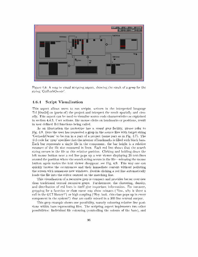
Figure 4.8: A map in visual scripting aspect, showing the result of a grep for the
string `GetLockOwner'.
4.6.4 Script Visualisation
This aspect allows users to run scripts, written in the interpreted language
Tcl [Ous94] on (parts of) the project and interpret the result spatially and visu-
ally. This aspect can be used to visualise source code characteristics as explained
in section 4.4.3. User actions, like mouse clicks on landmarks or positions, result
in user de�ned Tcl functions being called.
As an illustration the prototype has a visual grep facility, please refer to
Fig. 4.8. Here the user has requested a grep in the source �les with target string
`GetLockOwner' to be run in a part of a project (same part as in Fig. 4.7). The
Tcl code for `grep' speci�es that the interior of landmarks is �lled with black bars.
Each bar represents a single �le in the component, the bar height is a relative
measure of the �le size measured in lines. Each red line shows that the search
string occurs in the �le at this relative position. Clicking and holding down the
left mouse button near a red line pops up a text viewer displaying 20 text-lines
around the position where the search string occurs in the �le|releasing the mouse
button again makes the text viewer disappear, see Fig. 4.9. This way one can
quickly browse the occurrences and their immediate context without polluting
the screen with numerous new windows. Double clicking a red line automatically
loads the �le into the editor centred on the matching line.
This visualisation of a recursive grep is compact and provides better overview
than traditional textual recursive greps. Furthermore, the clustering, density,
and distribution of red lines in itself give important information. For instance,
grepping for a function or class name may show misuses (`Now, why is there a
call in the GUI library?') or high coupling (`Hey, look, this class pops up in every
component in the system!') that are easily missed in a 300 line textual output.
This grep example shows one possibility, namely colouring relative line posi-
tions within bars representing �les. The scripting aspect implements two other
possibilities: Individual �le colouring (controlling the colours of the bars), and
96
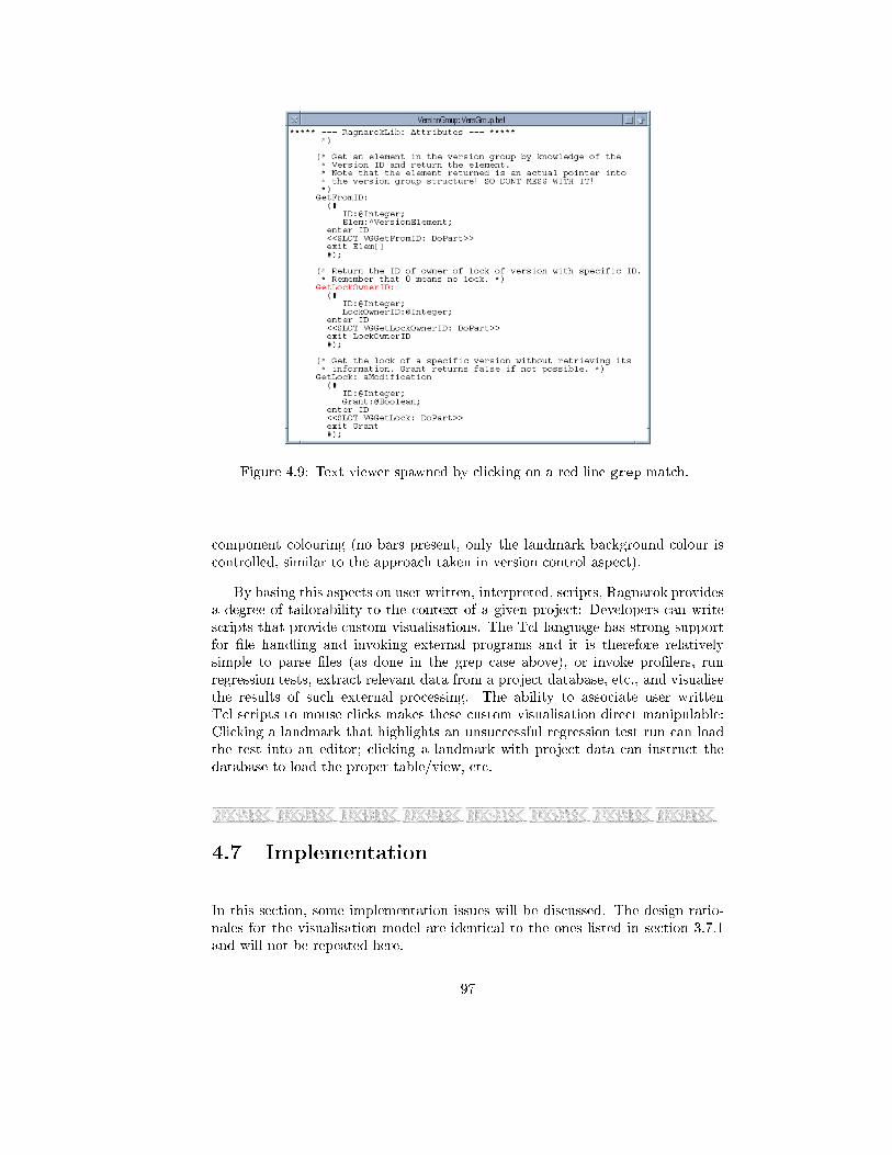
Figure 4.9: Text viewer spawned by clicking on a red line grep match.
component colouring (no bars present, only the landmark background colour is
controlled, similar to the approach taken in version control aspect).
By basing this aspects on user written, interpreted, scripts, Ragnarok provides
a degree of tailorability to the context of a given project: Developers can write
scripts that provide custom visualisations. The Tcl language has strong support
for �le handling and invoking external programs and it is therefore relatively
simple to parse �les (as done in the grep case above), or invoke pro�lers, run
regression tests, extract relevant data from a project database, etc., and visualise
the results of such external processing. The ability to associate user written
Tcl scripts to mouse clicks makes these custom visualisation direct manipulable:
Clicking a landmark that highlights an unsuccessful regression test run can load
the test into an editor; clicking a landmark with project data can instruct the
database to load the proper table/view, etc.
4.7 Implementation
In this section, some implementation issues will be discussed. The design ratio-
nales for the visualisation model are identical to the ones listed in section 3.7.1
and will not be repeated here.
97
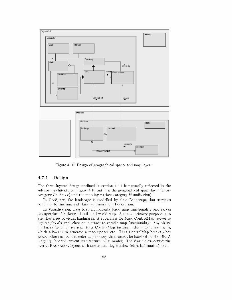
Figure 4.10: Design of geographical space- and map layer.
4.7.1 Design
The three layered design outlined in section 4.4.4 is naturally re ected in the
software architecture. Figure 4.10 outlines the geographical space layer (class-
category GeoSpace) and the map layer (class-category Visualisation).
In GeoSpace, the landscape is modelled by class Landscape that serve as
container for instances of class Landmark and Decoration.
In Visualisation, class Map implements basic map functionality and serves
as superclass for classes detail- and world-map. A map's primary purpose is to
visualise a set of visual landmarks. A superclass for Map, ControlMap, serves as
lightweight abstract class or interface to certain map functionality: Any visual
landmark keeps a reference to a ControlMap instance, the map it resides in,
which allows it to generate a map update etc. Thus ControlMap breaks what
would otherwise be a circular dependency that cannot be handled by the BETA
language (nor the current architectural SCM model). The World class de�nes the
overall Ragnarok layout with status line, log window (class Informator), etc.
98
Consistency is maintained between landscape landmarks and visual landmarks
through an observer pattern [GHJV94]. A state pattern [GHJV94] within class
VisualLandmark implements the processing and visual appearances relevant for
di�erent aspects.
The design is implemented in the BETA programming language [MMPN93]
and consists of about 18000 lines of code on top of the architectural software
con�guration management code.
4.7.2 Landscape Resolution
Landscape coordinates are 32-bit integers in our present implementation. One
concern with this choice is resolution. Obviously we can `zoom in' to the extend
where we run out of resolution, for instance if we try to de�ne a rectangle between
position (10,10) and (11,11).
The problem is less severe than one might expect, though. Starting a new
project, Ragnarok automatically de�nes the �rst landmark and defaults the
world map scalefactor. The scalefactor is about 885.000 and the initial landmark
is bounded by the rectangle (0, 0, 100.000.000, 100.000.000) giving an initial
118 x 118 pixel rectangle on the world-map. These numbers give amble room
for expanding the root landmark (about a factor 40) before having resolution
problems. Assuming that sub-landmarks typically have widths and heights that
are one �fth of their parent's sizes, we can nest to depth 7{8 without problems.
Assuming on average four part-landmarks per parent landmark this would give
room for 64K landmarks at depth 8.
If this does not provide adequate resolution, a more elaborate implementation
of the landscape is outlined in [Chr96] that overcomes the resolution problem.
4.8 Case Studies
The Ragnarok prototype provides most of the functionality of the RCM pro-
totype. It has therefore been natural to ask the teams in the SCM case studies,
section 3.9, to migrate to the visual, geographic space based, user interface. This
migration has been slow, however, for a number of reasons. At present, the Rag-
narok prototype is used by the ConSys team and in the Ragnarok project
itself|however the compiler team has not made the transition from RCM yet.
The ConSys team started using Ragnarok medio summer 1998.
4.8.1 Interview
As was the case with the previous interviews, an interview guide provided the
framework for an open-ended interview [Pat80]. The guide contained 37 ques-
tions in 8 major groups: Overview and navigation, world/detail map correlation,
mediating landscape, collaboration, visualisation framework, landscape stability,
and relations to architectural- and SCM model. The ConSys team was interviewed
autumn 1998. The interview was recorded on tape. The Ragnarok prototype
has not been instrumented, thus no usage statistics data is available.
99
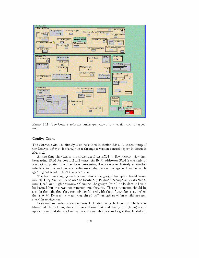
Figure 4.11: The ConSys software landscape, shown in a version control aspect
map.
ConSys Team
The ConSys team has already been described in section 3.9.1. A screen dump of
the ConSys software landscape seen through a version control aspect is shown in
Fig. 4.11.
At the time they made the transition from RCM to Ragnarok, they had
been using RCM for nearly 2 1/2 years. As RCM addresses SCM issues only, it
was not surprising that they have been using Ragnarok exclusively as another
interface to the architectural software con�guration management model while
ignoring other features of the prototype.
The team was highly enthusiastic about the geographic space based visual
model: They claimed to be able to locate any landmark/component with `light-
ning speed' and high accuracy. Of course, the geography of the landscape has to
be learned but this was not reported troublesome. These statements should be
seen in the light that they are only confronted with the software landscape when
doing SCM. Even so they get acquainted well enough to claim con�dence and
speed in navigation.
Positional semantics was coded into the landscape by the layouter: The Kernel
library at the bottom, device drivers above that and �nally the (large) set of
applications that de�nes ConSys. A team member acknowledged that he did not
100
know this scheme but this, nevertheless, caused no problem with navigation. An
amusing observation was that the stable, old, architecture was at the left while
new landmarks/components were always added right of the existing ones. Thus
the left-right orientation of the landscape has connotations of age and stability.
Some components are `core' entities, frequently visited for check-in or -out,
while others are rarely visited. They reported that they knew the location of core
components by heart while the others were found iteratively: A detail-map was
opened over the relevant region, then reading component names allowed them to
�nd the proper one. They were never in doubt about what region of the landscape
to start this iterative search in, thus it is still very quick.
In trying to concretise what facilitate their navigation they emphasised that
landmarks should be given irregular sizes and positions, avoiding nice-looking but
`anonymousing' alignments. They had not used decorations at all, but did not
believe their presence would have improved navigation anyway. Other shapes
than rectangles were requested, however.
The team found that the version control aspect map provided much enhanced
overview of the project SCM state compared to what was available in the RCM
prototype. The colour coding provides �ne overview of newer versions in the
repository and provides information about components under revision, i.e. `what
is going on', in supplement to verbal communication. Again, the mere location
of a coloured landmark is usually enough for the developers to know the identity
of the component, or at least give a good hunch of what it is part of.
One technique, the team has (re)invented, is to de�ne a workspace that is used
only to contain the latest system release. Thus, to see what has been changed since
last release they only have to open a version control map using this workspace
and the light red coloured landmarks will tell immediately.
The team is not educated in design notations like UML so they were not able
to evaluate the value of having such documentation within a development environ-
ment. Understandably, they did not feel the software landscape had contributed
to their understanding of their system nor facilitated communication.
The discussion, however, lead to the conclusion that, apart from the Kernel
library, the structure manifested in Ragnarok was more related to the physical
than the logical architecture. This conclusion is in contrast to the claims made
during the previous interview, section 3.9.4. The contrast is interesting, however,
as it supports an observation made in the Ragnarok project itself. Here, it was
observed that the components were created for di�erent reasons in RCM and in
Ragnarok. The RCM `look-and-feel' is that of a shell and this automatically
makes you think in terms of physical structure. To add some documentation, it
feels natural to create a Doc component: cc Doc and makedir Doc doesn't feel
that di�erent. In Ragnarok, the `look-and-feel' is that of a software design tool
and this unconscious focusing of the mind makes you create di�erent components:
You simply do not create a Doc landmark as it does not make sense in the
UML diagram; instead you associate the documentation directly to the proper
component. Especially seen in the light that the ConSys team does not know
graphical design notations, it seems plausible that the RCM prototype has made
it natural primarily to code the ConSys physical architecture into a structure that
now forms the landscape.
101
A less fortunate point was that since the introduction of Ragnarok, the team
has forgotten to set functional dependency relations between new components. As
these are not shown they are of course easy to forget.
Ragnarok
We take the liberty to add some observations from using Ragnarok in the Rag-
narok project itself. This project has been developed using more traditional
tools, Emacs editor and a command line compiler, that provides less support
than Visual Studio: No class browser, build-in grep, etc.
Our experience supports the observations of the ConSys team: The landscape
is quickly learned and components located fast and with high accuracy. Especially,
the world map is an eÆcient �le browser as stated in section 4.6.2.
The visual grep is good, especially in two aspects: The location of red match
lines provides compact overview, often you identity the one you are interested in
simply by its location. For instance, interface �les are generally the �rst black
bar in a class component so a grep match of a method name appearing in that
bar is the method de�nition. Browsing is strong as the matching line as well as
it immediate context is visible (as in the pop-up text window, Fig. 4.9). (The
usefulness of the latter was vital for a particular bug in the prototype: An empty
line was printed on the console occasionally, obviously an unfortunate left-over
from a set of debugging output statements|but where? The BETA statement
`newline' is correctly used in many places, and ordinary recursive grep could bring
no useful information. It was the context of the newline that was important and
made it easy to spot the culprit.)
4.8.2 Summary
Though only limited aspects of Ragnarok has been used, the statements do
support some of the claims forwarded in section 4.3:
{ Overview: The version control aspect colour coding was valued as giving
accurate, broad-brush, information about the current state of the ConSys
project; with respect to the individual developer's progress, and with respect
to the last release. For instance, Fig. 4.11 essentially summerises progress
and current status of over 240.000 lines of C++ code.
{ Navigation: The team expressed enthusiasm about the geographical location
metaphor and claimed fast navigation with high accuracy.
{ Sharedness and progress: The version control aspect was also reported to
complement verbal communication about what other team members are
working on and how the project progresses.
{ Script visualisation: The ability to visualise properties of the architecture's
underlying data, as exempli�ed with the grep script visualisation, provides
a compact representation of a potential large dataset while enabling easy
browsing of details. The experiences with grep indicate the usefulness of
the approach for other data extraction techniques.
102
An interesting change request for the prototype was put forward by the Con-
Sys team. Originally the text in landmarks in version control aspect maps was
modelled over the RCM command line, for instance as seen in Fig. 4.7 the Source-
Component landmark text reads 7:SourceComponent(v126#) which lists compo-
nent name before version identity. The ConSys team requested that the order
was reversed, version identity �rst, so the above example instead read (v126#)
7:SourceComponent. The argument was that in very small landmarks, only the
�rst portion of the string is visible and this limited information should state the
version identity rather than component name because component identity is easily
inferred from landscape position.
4.9 Discussion
Having an explicit and well-communicated architecture is the �rst step
towards ensuring architectural conformance. Having an environment
or infrastructure that actively assists developers in creating and main-
taining the architecture (as opposed to just the code) is better. This
means that we need tools for architecture development to complement
our existing ones for code development.[BCK98]
The Ragnarok visual model is characterised by the following properties:
{ Spatial, hierarchical, organisation of architectural entities in a software land-
scape.
{ Broad-brush documentation of architecture through decorations, speci�cally
support for modelling notations.
{ Landmarks mediate daily development and management activities and in
return provides visual feedback on the result of an action.
{ Landscape creation and manipulation automatically creates and modi�es
the underlying architectural framework.
{ Maps visualise regions of the software landscape and provides a natural
formalism for handling geographic space.
{ The aspect property of maps allows data of the underlying components to
be overlaid a positional stable landscape.
{ The landscape is shared between all team members.
In terms of usability these properties are argued to achieve the following goals
{ Enhanced navigation: Spatial memory can eÆciently be used to locate (es-
pecially core) architectural components.
{ Overview: Typical 3-5 levels of granularity of the architecture is presented
compactly. Team members can quickly zoom in and out of the landscape
based upon whether detailed- or a general view is wanted.
103
{ Decorations allow the landscape to become a logical software design docu-
mentation.
{ The landscape becomes a common and manifest reference-frame for stake-
holders with di�erent expertise and thus promotes high-level communica-
tion.
{ Mediating landscape eases access to underlying data, tasks, and develop-
ment processes and counteracts that design documentation is forgotten or
becomes out-of-date.
{ Development progress and architectural modi�cations are visualised in-
stantly through a shared landscape.
{ Di�erent aspects of the software architecture visualised overlaid the same
stable landscape which eases comparisons.
Presently, the case study results are still tentative. We feel, however, that we can
state with con�dence that:
{ The proposed model does enhance navigation; users con�dently and ac-
curately identify components and access their data solemnly based upon
landmark positions.
{ Decorations and salience of landmarks are not essential for a navigable land-
scape: Irregular sizes and positions of landmarks provide suÆcient visual
clues, at least for small- to medium sized projects.
{ Overview is strengthened. The whole architecture can be viewed in a single
map, and for instance identifying components under revision and newer
versions is fast and direct compared to the RCM textual output.
{ The world map acts as a fast and accurate �le browser for the project.
{ Visualisation of recursive grep is valuable, provides enhanced overview com-
pared to textual output, and the direct interaction with the visual repre-
sentation of string matches (viewing region around match or telling editor
to centre on match) enables fast browsing of context and a quick loading
scheme.
4.9.1 A Cognitive Dimensions Evaluation
Green and Petre has proposed a `Cognitive Dimensions' framework as a broad-
brush evaluation technique for visual notations [GP96]. Developed with visual
programming environments in mind, it nevertheless provides valuable insight for
other domains as well.
The dimensions that are relevant for Ragnarok's visual model are:
{ Abstraction gradient: What are the minimum and maximum levels of ab-
straction? Can fragments be encapsulated forming new abstractions?
{ Error-proneness: Does the notation induce `careless mistakes'?
104
{ Hard mental operations: Are there situations where the user needs to resort
to pencil and paper to keep track of what is happening?
{ Hidden dependencies: Is every dependency overtly in both directions?
{ Premature commitment: Are users forced to make decisions before they
have the information they need?
{ Role-expressiveness: Can the reader see how each component relates to the
whole?
{ Secondary notation: Can layout, colour, and other cues be used to convey
extra meaning, above and beyond the semantics of the notation?
{ Viscosity: How much e�ort is required to perform local changes?
{ Visibility: Is every part simultaneously visible? Is it possible to juxtapose
any two parts side-by-side at will?
Before discussing each in turn it should be noted that Ragnarok is a prototype
so in many respects there is a gap between what exists and what is envisioned.
Ad. Abstraction gradient: Though Ragnarok's understanding of software
architecture and architectural software con�guration management is all about
hierarchical structuring of abstractions, we must admit that the visual model
is, what Green and Petre term, abstraction-hating. Landmarks are be nested in
hierarchies re ecting the underlying architecture, and moving a landmark also
moves its substructure|but we cannot group landscape features, landmarks and
decorations, into a composite that can be instantiated in di�erent places.
This is a deliberate decision, though. Replicating a set of landmarks in several
places in the landscape would also replicate the underlying source code; and reuse
of software is to be preferred over copying software (cut'n'paste programming).
How to visualise reuse of architectural structures, typically design patterns, in
multiple places in the landscape is another issue, discussed in section 4.12.2.
Ad. Error-proneness: Presently, the syntax for de�ning and modifying the
landscape is awkward to put it mildly. It was de�ned ad hoc and only with ease
of implementation in mind: The purpose was to validate the value of a geographic
space metaphor for visualising architecture, not eÆcient user handling. Thus one
easily de�nes the wrong type of decoration or modi�es a landmark in a wrong
way. Of course the long-term goal is to provide a better and more reliable user
interface.
Ad. Hard mental operations: Modi�cations of the landscape are straight
forward operations with instant feedback on the outcome. As it is not possible
to group interactions or constructs there is thus no way of these interacting in
`mentally hard' ways.
Ad. Hidden dependencies: A short-coming of the present implementation is
that only compositional relations are directly visualised, through spatial contain-
ment. Other types of relations, like functional dependency and inheritance, are
not automatically generated by the visual model and developers must add these
as decorations themselves and make sure that they are consistent. As the ConSys
105
team proves, this may very well result in the dependencies not being de�ned at
all. We consider this a severe problem that must be addressed in future work.
Ad. Premature commitment: Studies of the programming process tells what
all developers know: Programs are not developed in a linear fashion. Developers
make rapid shifts between high level and low level and often revise already writ-
ten code. Ideally, we should allow a similar process for landscape and thereby
architecture development. Unfortunately, Ragnarok does not support such at
present. In order for a landmark be created, it must be created with the context
of some other landmark (the root landmark is created automatically by Rag-
narok when a new project is launched). This enforces a top-down working style,
at least on the overall architectural design. In other words, the architect is forced
to commit prematurely to a design before information on its quality is available.
However, this may not be all that di�erent from current practice; a team has to
commit itself to an initial architecture before the implementation phase anyway,
like setting up a directory structure in order to create �les, etc. Also, the land-
scape can be changed and rearranged (but doing so constantly of course severely
deprives us the advantage of spatial memory).
Ad. Role-expressiveness: Green and Petre describe role-expressiveness as `in-
tended to describe how easy it is to answer the question \what is this bit for?"'.
Obviously, role-expressiveness is at the heart of the Ragnarok visual model:
Understanding and overview of a software design is one of its main goals. A de-
veloper well-versed in UML class diagrams (or whatever notation adopted in the
team) should hopefully have little diÆculty in grasping the overall architectural
picture manifested in the software landscape.
Ad. Secondary notation: Decorations are secondary notation, allowing devel-
opers to annotate the landscape and thereby their architecture with whatever
additional information that may guide those confronted with the landscape.
Ad. Viscosity: Viscosity addresses how diÆcult it is to perform local changes.
Again, the prototype implementation is awful at present. Moving a landmark
moves its substructure; decorations, however, are isolated entities with no relation
to the landmarks they supposedly provide secondary notation for. Thus, moving a
landmark would mess up the UML class diagram notation. Clearly, the long-term
goal is to avoid this.
Ad. Visibility: The visibility dimension is well supported: Through maps any
part of the landscape can be viewed in any scale, any level of detail; and di�erent
maps can juxtapose distant areas side-by-side for easy comparison, or di�erent
aspects of the same region can be viewed simultaneously.
4.9.2 Salience|or the lack of it
Our initial psychological motivation (section 4.2) emphasised salience of land-
marks. It is the peculiar and salient landmark we note; a town where all houses
were alike would quickly make us loose our sense of direction.
Looking at any of the examples in section 4.6, it is clear that salience is not
a property of landmarks in the current Ragnarok implementation. On the
contrary, landmarks are stereotypical rectangles.
106
A solution that immediately springs into mind is simply to make the landmarks
salient, e.g. by representing them as bitmap images, use a wider range of geometric
shapes than just rectangles, etc. These suggestions have some problems. Images
deprive the landmarks their transparency property that is important in aspects
concerned with overview where viewing 3{4 levels of the architecture is important.
Also, if the landscape is to re ect a UML class diagram inspired documentation
of the logical architecture, the room for creativeness is rather limited due to
the prevailing `rectangle-o-mania' of most notations (the Booch `clouds' being an
exception).
Let us step back one moment, however. The wish for salience is to provide
visual clues that allows us to identify positions fast and unambiguously. That is,
salient landmarks are not a goal in itself but means to achieve sense of locality. It
seems this can be achieved without landmark salience. The trick is to let the space
between landmarks as well as existence of decorations act as `beacons' instead.
As reported by the ConSys team, irregular sizes and positioning of landmarks
are important factors in unambiguously identifying a given part of the landscape.
As their landscape is completely devoid of decorations, they rely only on this
to give sense of locality|and report that they succeed. As for the Ragnarok
project itself, the numerous decorations, whose primary purpose is UML class
diagram documentation, all serve an important secondary purpose as `beacons'.
(The somewhat unfortunate conclusion is that what we denote `landmarks' have
less `landmarkness' than other entities in the landscape.)
Another idea is to `humanise' rectangles. Ask any person to drawn �ve rect-
angles on a piece of paper|and none of them will be exactly alike. In a design
project at our university, one researcher noted that it was easier to overview
and navigate the initial hand-drawn diagrams than the later machine generated
ones. If one could draw the rectangles in an `unperfect', but reproducible un-
perfect, way|edges incorrectly joined, varying gray-levels and width of lines,
sloping/curved lines|these small cues may provide better salience of landmarks.
This task is more demanding than it may sound; a small, naive, experiment was
quickly abandoned as it produced rectangles that were ugly and still looked very
`machine-ish'. Producing shapes that could pass as being made by a human, may
be a topic in its own right.
4.9.3 Positional Stability|or the lack of it
Positional stability is even more important than salience for our sense of locality.
The occasional reorganisation of shelves in the favourite supermarket costs a lot
of extra time shopping the �rst couple of times.
Consequently, for the proposed visual model to be bene�cial, we must assume
a relatively stable landscape|and thereby a relatively stable architecture. Is this
a viable assumption in general? This question has several facets.
First, there is a question of granularity of change. It is reasonable to believe
there is no major architectural reorganisation taking place every second day. (If
this is indeed the case, the team has a serious problem, much worse than lost
sense of direction in the landscape.) Most architectural rearrangements will take
place at a relative �ne level of granularity: Adding some classes, change a few
dependencies, etc. These should be possible without major e�ect on the overall
107
architecture and landscape, and thus the overview and overall framework for
navigation should be evolving slowly.
Secondly, once a given architecture is largely implemented it is very costly to
do major reorganisations: Much code must be modi�ed leading to introduction
of new and even old bugs requiring new rounds of testing and debugging.
The question of positional stability has implications also for what phase of a
development project the Ragnarok visual model is most eÆcient for. Clearly
early analysis and design phases are characterised by rapid and radical changes in
the overall structure and an approach based on stable positions is less valuable.
In this phase, clearly, the tool must provide additional navigation tools, like e.g.
searching for a component with a given name.
The result from the case study, that location-based search is e�ective, has
wider implications. There is an abundance of graphical design- and architecture
notations and numerous tools to create and edit such diagrams, CASE tools being
a special class. Therefore one important conclusion of the experience with the
visual model can be summed in a recommendation for users of ordinary diagram-
and CASE tools:
It is recommended that the spatial layout of diagrams should be as
stable as possible.
4.9.4 Other Architecture- and Project Views
Ragnarok visualises the logical design architecture. As Green and Petre points
out [GP96, p. 134], any visualisation has a cognitive �t to the problems at hand;
and there is inherently a trade-o� between di�erent views: A visualisation focus-
ing on data- ow makes it diÆcult to express and overview control ow whereas
the opposite is true in a control ow focused visualisation.
Clearly, the tasks that are cognitive �t with a logical view are well supported
by Ragnarok and as we have tried to argue, there are many important tasks in
software development that �t well.
There are other tasks and views that are less �t for this visualisation. During
a project's planning phase, tasks must be de�ned, sta�ed, and scheduled; here
the emphasis is on the time aspect and Ragnarok's visualisation unsuitable.
4.9.5 Visualisation and Architectural Consistency
On several occasions, questions have been raised concerning Ragnarok's ac-
curacy and consistency of the visualised architecture (as-designed, see [Kaz96])
compared to the system's real architecture (as-built) as manifested by the under-
lying source code.
First of all, Ragnarok does not attempt to ensure such consistency at
present. Secondly, Ragnarok does not attempt to reverse engineer or recon-
struct the architectures of existing systems. Both endeavours are candidates for
future research. However, they are not considered high priority for two rea-
sons: Consistency is diÆcult to ensure, and secondly Ragnarok's visualisation
is meant to stress overview even at the expense of accuracy.
108
The dream of perfect synchronisation between design and actual code is an
old one. Commercial CASE tools generate source code from design diagrams, and
some attempt to reverse engineer existing source code back into diagrams; often
producing a result of little or no value. The Freja CASE tool [CS96, San93a] is tak-
ing this to the extreme as both it and its cousin, the Sif structure editor [San93b],
directly manipulate the underlying abstract syntax tree; and therefore with some
weight claims a one-to-one correspondence between design and code. In our opin-
ion, even the Freja approach su�ers major problems. To handle relations, like
composition and association, between classes, Freja must rely on using a small
set of standard implementations; implementing a relation in another way (say,
to achieve better speed or size performance) means that it will not show in the
design diagram and thus will introduce a discrepancy.
Another and perhaps more important question is what purpose a architec-
tural/design description has: Conveying the `grand picture' or absolute accuracy?
Any realistic piece of software will contain a large number of classes that support
actual implementation but have little relevance for the overall architecture. This
is even more pronounced if one considers the relations between all classes. Show-
ing these components and relations in an architectural view generates noise that
may be annoying at best and severely damaging overview at worst.
Of course, one can argue in length whether this postulate is true, and one may
also rightly argue that everything is important at some level of detail. However,
as an example, consider classes, well-known from most APIs, like Date, Button,
and MenuItem. Though important in the API development project, there will
be thousands of other projects where architectural diagrams would be obscured
if every component using e.g. Date should draw a UML association-type line to
this class. Another concrete example is given by Kazman: The Dali architecture
reconstruction tool [KC99] relies heavily on interactive �ltering by an expert with
code insight to produce an understandable architecture from the source code of
a system|in the initial stage where all components and relations are extracted
from the raw code, diagrams are an unwieldy tangle. The standpoint taken in
Ragnarok is that the interpretation and understanding of an architecture is
important.
4.9.6 The Captivating Third Dimension
The Ragnarok user interface does not claim a comprehensive psychological foun-
dation, but nevertheless Tolman's theories underpin the work. But these theories
deal with human navigation in a physical world, not navigation on a map. Anyone
who has tried to make sense of a map knows that relating features of reality and of
a map can be diÆcult. This poses the question: Can we transfer our claimed �ne
spatial perception to the process of dealing with maps as Ragnarok implicitly
does?
A master student at DAIMI has addressed this question indirectly, namely
by trying to drive the spatial metaphor to its limit. Using the virtual reality
modelling language, VRML, he has created a virtual, 3-dimensional, software
landscape for the Ragnarok project [Gr�98]. In his model, components are
visualised as boxes, hierarchical composition by stacking: A part component's
box is stacked on top of the box representing the component, it is part of. This
109
was chosen as a zenith view of the box world is similar to the well-known 2D
landscape of Ragnarok.
Three dimensions hold some promises. A box has �ve visible sides in this box
implementation and therefore more space available for displaying information.
And three dimensions may also provide a higher level of salience, as there is more
space available for varying shapes and provide texture. Also humans are more
used to navigation in three dimensions than on maps.
The lessons from Gr�h�j's work, however, suggest that it is diÆcult to realise
the envisioned potential; at least in the simple stacked-box approach adopted.
Two major problems were identi�ed:
{ Navigation problems. The VRML browsers have too many degrees of free-
dom in navigation so often the landscape tilts dramatically, turns upside
down, etc. If very detailed control of the controls is not exercised, the re-
sulting travel is very unlike everyday experience|we seldom move around
our town or house ying upside down.
{ Lack of transparency. In contrast to the usually transparent Ragnarok
landmarks, the boxes were opaque. Thus if the landscape was viewed from
one of the sides, most landmarks are obscured by those in front.
Some of these problems may be remedied: Providing navigation controls that
make travelling more like everyday experience; boxes may be displayed as wire-
frames instead of opaque objects, etc. Still, the conclusion is that going to 3D
is not straight forward, and it requires future work and research to make the
extra dimension a bene�t. Another point is that maps, as used in the present
2D Ragnarok, have some intrinsically nice properties. Travel in physical space
takes time; pointing at a location on a map and being transported there instantly
is fast|an old dream that is still science �ction. A 3D based user interface will
probably make use of some kind of maps (3D maps?) to provide this functionality.
4.10 The Potential of Geographic Space
In section 4.4.3 and 4.6 some potential aspects and examples of using geographic
spatialisation were described. However, we think the idea holds further promise.
It should be emphasised that these ideas are untested at present.
4.10.1 Geographic Space for General Purpose Visualisation
The visual model has been presented in the context of software architecture and
software development. We think, however, that the model has wider use.
In general, the model seems viable for hierarchical, relatively stable, structures
that are negotiated often by a set of users. Stability has already been discussed,
but it is also important that spatial memory fade (as any human memory) and
consequently the model seems less interesting for structures that are seldom vis-
ited. The map aspect property is also interesting for structures where entities
hold data in multiple dimensions.
110
An obvious candidate for visualisation using the model is �le-system directory
structures, as an alternative to, e.g., MacFinder, Windows Explorer, or the shell
cd and dir/ls commands.
4.10.2 To Work is to Be (Somewhere)
Envision a very close binding between the Ragnarok environment and a pro-
gramming language environment or source code editor. Then Ragnarok could
receive continuous and detailed information about what parts of the software the
individual developer is working on. And, to work in the architecture means to be
in some speci�c position in the software landscape. Thus, a natural step could
be to visualise presence in the landscape. People that are working very closely
together should be able to tell Ragnarok to display the presence of a selection
of other team members, perhaps in the form of telepointers, as explored in for
instance Self [SMU95]. In a same-time, di�erent-place, setting these cursors could
act as channels of communication by for instance establishing a audio- or video
link to the person, the cursor represents.
This way, an awareness of work progress is visualised in a very concrete and
direct way. Also, potential con icts may be solved even before they are born, as
developers may postpone working on parts of the system that they can see other
developers are currently modifying.
The outlined idea, however, also carries the seed of misuse and a avour of
`Big Brother is Watching You'. It may quite easily give the individual developer
a sensation of `the manager is watching me all the time'. Whether the technique
is a bene�t or a pain is a question the individual team must answer.
4.10.3 Geographical Interpretation of Link Enactment
Hypertext and hypermedia is in wide use today, not at least as the underlying
paradigm for the world wide web. The concept of investigating items of interest
just by clicking a mouse button is a strong one, and hyperlinks also have many uses
in a programming- and development context. Well know examples include having
links between name uses and de�nitions in a programming language, between
code fragments and the description of the requirement, it implements, etc.
The problem with hyperlinks is that one can quite easily and quickly
loose one's sense of direction|a situation often termed `getting lost in hyper-
space' [MDR91]. After following a few links, you do not know where you are, how
you got there, how to get back to the main text/data, or what the context is of
the displayed material.
Ragnarok holds the promise of providing a spatial interpretation of hyperlink
enacting; enacting a hyperlink is metaphorically speaking a travel from one part of
a system to another. This travel could be visualised by a smooth movement of the
developers own cursor/cross-hair (see previous section) across a map; potentially
combined with a zoom and pan of the map's displayed region if the target location
is outside it.
111
4.11 Related Work
Few software development environments base their visualisation on a geographical
metaphor. However, similar approaches have been published in various other
�elds.
4.11.1 CASE tools
Looking at map (5) in Fig. 4.6, Ragnarok may resemble a UML diagram editor or
CASE tool, exempli�ed by e.g. Rational Rose [Ros]. However, the focus of CASE
tools and Ragnarok is di�erent.
CASE tools focus on improving developer productivity by allowing de-
sign to be drawn graphically in standard notations such as Booch [Boo91],
OMT [RBP+91], or UML [BRJ97], which is then used to generate a source code
skeleton. Often, tools are also equipped with reverse-engineering capabilities that
(at least in theory) allows diagrams to be kept consistent with implemented source
code. The problems of ensuring consistency between as-designed and as-built ar-
chitecture have already been touched upon in section 4.9.5. Though CASE tools
certainly serve an important role in emphasising high-level architecture over low-
level code, and the explicit visualisation of the architecture facilitate communi-
cation, it does not seem like a primary purpose. The tool usage seems focused
'up-front' and less so in implementation and maintenance.
In contrast, the emphasis in Ragnarok is foremost on making an architecture
manifest in a landscape used by all stake-holders in the project and let this land-
scape serve as mediator for most, if not all, of the tasks that must be performed
through the life-cycle of the project. The landscape furthermore serve as a visu-
alisation framework for a wide range of purposes, all the way from �nding strings
in the source code to locating components that exceed budget. This way, the
same architecture conveys meaning to a wider set of stake-holders than the more
design- and development oriented approach by traditional CASE tools.
Nevertheless, adding code generation and reverse engineering capabilities to
Ragnarok is of course appealing.
Another interesting, and teasing, question is the following: `If we take a CASE
tool (or diagram editor for that matter) and simply instruct our designers and
coders not to move the class- and class-category boxes unless it is absolutely
necessary|wouldn't we achieve the much the same functionality as Ragnarok?'
One aspect of the answer has already been given in section 4.9.3, namely that
the recommendation of positional stability is a good one, so in this respect one
would achieve some of the same bene�ts. On the other hand, Ragnarok provides
a great deal of functionality that supports the underlying space metaphor, not
found in ordinary CASE tools: Ragnarok o�ers the choice of choosing the level
of abstraction at which to view the design, through the depth parameter; in
contrast most CASE tools only support a single level of abstraction. A mediating
landscape emphasises an active and daily use of diagrams more than ordinary
diagram tools; maps emphasise the underlying spatiality; and by overlaying the
same landscape with di�erent data aspects more stake-holders are confronted with
the architecture.
112
4.11.2 Pad
Another interesting comparison is to Pad++[BHP+96, BH94, PF93]. Pad++
is an innovative and powerful 2D visualisation system. In Pad++ the user ma-
nipulate objects on an in�nitely zoomable 2D surface. The Pad++ system in-
corporates a very e�ective engine for panning and zooming. The objects on the
surface are text, simple graphics, and images. The underlying landscape metaphor
employed in Ragnarok is similar to the in�nitely zoomable (`rubber') surface in
Pad++.
One di�erence is the map layer that is put between the user and the landscape.
A map has the aspect property that only with some diÆculty can be simulated
in Pad++: Pad++ provides portals that allows di�erent regions of the surface to
be viewed at the same time, and lenses that can provide di�erent visual presen-
tations of the same underlying object, say a slider or textual representation of an
integer object. Combining a portal and a lens would thus provide functionality
similar to a map; however the lens and portal object must be moved individually.
Another consequence is that an unbalance is introduced between the `true' land-
scape without lenses and the `distorted' one viewed through one or more lenses.
Map aspects in Ragnarok in contrast, are explicit that they represent just one
dimension of the `truth'.
The most important di�erence, however, is the objects handled. In Pad++
objects directly are on the Pad surface; in contrast landmarks serve as visual
representations of a complex, multi-dimensional, data-structure of the underlying
component. In other words, landmarks are not the actual data, as in Pad++.
Therefore Ragnarok uses the same region to visualise di�erent data in di�erent
aspect maps (e.g. grep matches or version information). Pad++'s portals and
lenses in contrast provide di�erent visual representations of the same data, say
a slider or textual representation of an integer object. The aspect property of
Ragnarok is essential because of the multi-dimensional nature of software.
4.11.3 SeeSoft
The visual scripting facilities are inspired by the interesting work in the Bell
Labs `SeeSoft' systems [BE96, BE95]. SeeSoft is a powerful tool for visualising
properties of text �les (source code) in a highly compact form. Individual lines
in the source code are represented by colour coded text lines, pixel lines or even
individual pixels. Compared to SeeSoft the Ragnarok visual layout is less compact
due to the `unused' space between the landmarks but on the other hand it carries
valuable information in itself compared to SeeSoft which sorts �les alphabetically;
an approach that does not take spatial memory into account over �le renames and
deletion/addition. The stable layout is important as it eases comparisons (like
pro�ling information before and after an optimisation phase) and the distribution
and density of `hot spots' in itself provides valuable clues to system properties as
mentioned in section 4.6.4.
4.11.4 SAAMtool
SAAMtool is a tool [Kaz96] developed to support architectural analysis, speci�-
cally in context of SAAM: the Software Architecture Analysis Method [KABC96].
113
Though the scope of SAAMtool is clearly di�erent, namely architecture analy-
sis, there are interesting similarities in the underlying emphasis. Kazman empha-
sises the tool's ability to aggregate architectural elements recursively and associate
meaningful semantics with elements at any level of abstraction; and aid in archi-
tectural design as a creative activity. Visualisation of the architecture helps as
a high-level communication between stake-holders with the team. Finally, it is
emphasised `... to be able to visualise information about a software architecture
in the same tool that we create and maintain the architecture'. Ragnarok tries
to go a bit further as the visualised architecture also mediates daily development
activities.
SAAM emphasises scenarios as a technique to capture and analyse architec-
tural quality attributes, such as portability, safety, performance, etc., and argues
that the tool should act as repository of scenarios. As an example a set of modi�-
cation scenarios were analysed and the implications visualised by sizing rectangles
representing the architectural components such that the large ones express more
modi�cations. An interesting line of future work would be to analyse if scenarios
can be viewed as annotations of components and thus be handled within the cur-
rent framework; then similar information could be made available in Ragnarok
by using landmark colour coding instead of size.
SAAMtool supports multiple views [Kru95] on architecture: Dynamic view,
code view, allocation to hardware, etc. These distinct views are interrelated
though links between the views' respective entities. As already mentioned in
section 2, Ragnarok perceive the logical/static architecture as the fundamental
and focus on this. This does not exclude that the technique of an underlying
geographic space metaphor and visualisation through maps to be employed on
other views. Though this would result in several, coexisting and interrelated,
landscapes (dynamic landscape, process landscape, etc.) we may still bene�t
from a spatial layout. The question is, of course, whether these views are stable
enough over time to enable building an eÆcient, spatial and cognitive, map.
4.11.5 Desktop Space Metaphors
No comparison is complete without contrasting the Ragnarok visual model to well-
known desktop space metaphors like the Macintosh Finder or Windows desktop.
In Finder, objects (�les/directories) are represented by icons that, when clicked,
expands into a window showing its contents (part objects). These only shows one
level of the part/whole hierarchy and therefore navigation typically spawns many
new windows. In contrast most Ragnarok aspects show 3{4 levels of the hierarchy
and thus shows context and avoids intermediate maps during navigation.
More important, however, is the underlying spatial model: In Ragnarok all
landmarks have a speci�c, relative, position with respect to all other landmarks|
you can always answer the question: `Does landmark A lie left of landmark B?'
In contrast, MacFinder objects only have a position relative to the window it
is part of but not to objects in other windows: You cannot tell the position of
MyMac:FolderA:Document1 relative to MyMac:FolderB:Document2 in general,
only where they are relative to each other in your current, transient, layout of
your desktop. Therefore the Finder spatial reference frame is weaker and more
diÆcult to remember, share, and communicate in a team.
114
4.11.6 Spatialisation of Hypertext
Spatial organisation has also received attention within the hypertext community.
An often reported problem with hypertext systems is the sensation of `getting-
lost-in-hyperspace' users experience after following many hyperlinks: Not knowing
where they are in the text, diÆculty in understanding how the viewed material
relates to previous material, and not knowing how to get back to previous mate-
rial.
A group at Xerox PARC has been working on spatial hypertext [Mar92, MI93,
MIC94, MI96] where text-nodes are organised in 2D space as opposed the tradi-
tional node-link traversal model. Use of a spatial hypertext prototype, Aquanet,
is reported in [Mar92]. Aquanet is a collaborative hypertext tool for knowledge
structuring tasks, like analysis and argumentation, and used in the reported case
study to organise information about automatic language translation tools.
In context ofRagnarok, their case study made some interesting observations,
though it was in a di�erent domain. The perhaps most important is that:
Instead of articulating how di�erent types of objects were related, users
conveyed implicit relational structures through the use of spatial lay-
out.
[Mar92, p. 57]
This observation supports our hypothesis about semantics of position, sec-
tion 4.5.1. In their model, they have deal with multiple references to the same
object through virtual copies: All copies share the same graphic appearance and
selecting one selects all visible copies. They do not report this problematic and
it addresses a problem the current Ragnarok prototype cannot handle, namely
that of reusing architectural bits in various parts of a landscape for documenta-
tion purposes, say an observer pattern [GHJV94] in di�erent contexts. They also
report the naturalness of proximity-based structures [MI93, p. 223], i.e. entities
that are logically related entities are located close to each other; an argument in
favour of Ragnarok's spatial containment.
4.12 Future Work
In its current state, it is fair to characterise the implementation of the visual
model as immature, and the experiences with it as insuÆcient. Some technical
obstacles have in part been responsible for the state of matter: The underlying
Lidskjalv graphical library for Windows NT has until recently been immature in
a number of key areas required by the Ragnarok visual model, resulting in the
late introduction of the prototype for the ConSys project. The BETA compiler
team has been reluctant to change from RCM to Ragnarok, primarily due to
lack of time, but also partly from an ergonomic point of view (a majority of the
team are savage `mouse-haters'), and because Ragnarok cannot be operated
from shell-scripts.
115
4.12.1 Visualising Relation Types
Compositional relations are visualised using spatial containment. The underlying
software architecture model allows other types of architectural relations to be
stated also, such as functional dependency and inheritance, but these are not
visualised presently. An obvious way to visualise these is to use the `box-and-line'
approach, i.e. use decorations to show these relations coded in, say, UML.
The main reason that the prototype does not already visualise these relation
types this way, is the complexity of implementing a reasonable layout algorithm
as well as an intuitive user interface|an interesting exercise but beyond the scope
of the current work.
However, it is important to provide this visualisation as is particularly stressed
by the interview of the ConSys team that had forgotten to state dependencies after
the introduction of Ragnarok.
4.12.2 Visualising Architectural Reuse
One of the mantras in our quest to reduce software costs is reuse. Reusing a
component or a sub-con�guration of components is important in any project, but
may pose a special problem in the context of our visual model. As an example,
consider a container class hierarchy de�ned in a library component that we want
to use in, say, both a business- and graphics module. If we want to document this
explicitly in class diagram notation on the landscape we may easily end up wanting
to show the same container component in di�erent places in the landscape; but
the Ragnarok visual model demands that a component is assigned a unique
position and thus the same container classes cannot be displayed both in the
library, business- and graphics regions of the design landscape.
To overcome this problem, we need to partially compromise our requirement
that `things are in one place only'. Our suggestion is to provide `shadow' land-
marks (shown grayed or with special frames for instance) that act as links to the
real landmarks, positioned elsewhere in the landscape. Aquanet has explored this
technique, where replicated entities are denoted virtual copies [Mar92]. Actions
are forwarded to the real landmark and a special action should be to initiate a
zoom and pan travel to the real landmark.
4.12.3 Run-Time Aspect De�nition
Requirements on visualisations vary from one project to another. Providing just
the right set of map aspects for any given situation therefore seems like a never-
ending story.
Instead of hard-coding how an aspect acts with respect to processing data in
the underlying components and how the result should in uence landmark appear-
ance, we would like to de�ne a schema or language that allows users to provide
their own aspects at run-time.
4.12.4 Semantic Zoom
Pad++ (section 4.11.2) introduced the concept of semantic zooming, i.e. the
appearance of an object varies according to the zoom level it is seen in. Ragnarok
116
presently have limited support for this capability (e.g. if visual landmarks are
very small, they do not try to put text in the interior), but it is an bene�cial
extension: When landmarks appears physically small on the display they should
only convey summary information as e.g. a colour coding; when zoomed in the
landmark itself could begin to display more detailed information in its interior.
117

118
Chapter 5
Bridging the Gap
The main contributions of the present work are the architectural software con�gu-
ration management model and the geographical architecture visualisation model.
Both contributions can be described and understood with little reference to the
other. A future goal is to `bridge the gap' between these two e�orts and join them
into a more cohesive whole. A bridge must be passable in both directions|in our
context this leads to the questions of versioning the landscape and visualising
version control in the landscape.
5.1 Versioning the Landscape
The underlying software architecture is under version- and con�guration-control.
Presently, this is unfortunately not the case for the landscape. Ideally, checking
out an old version of a system should reestablish the landscape as it appeared at
the time of check-in.
This simple and natural idea, however, opens a potential can of worms in case
of mixed con�gurations. It is not diÆcult to imagine an older sub-con�guration
whose sub-landscape occupies a region now occupied by other landmarks. Thus,
checking out this sub-con�guration would render the full landscape illegal at worst
or messy and unreadable at best. However, we think this problem is an intrinsic
property that cannot easily be remedied. Rather, one should support switching
between the two landscape versions in order to compare the two.
119
5.2 Visualising Versions
Each landmark represents a component, or more correctly, the component version
presently in workspace. But each component version is member of the version
group representing the evolution of the component. The version control aspect,
outlined in section 4.6.3, focus on latest development only, not on historical as-
pects. But history is important, and the question is how to visualise this naturally
and simple? This may be especially important in our case as the architectural
model handles con�gurations and thereby historical, evolving, relations between
components.
A proposal is envisioned where a historical map aspect could visualise version
graphs inside landmarks, and the individual component versions could be linked
with arrows showing the relations. This enables a visual presentation looking like
the �gures presented in chapter 3. Only arrows for the rooted con�guration of
a selected component should be shown to avoid a mess of arrows. The selection
of a component version could simply be mouse clicks on the visual presentation.
Also, clicking on individual component versions should allow developers to browse
more detailed version information (log messages, author, date, etc.).
Other useful visualisations entail describing number of code changes (sub-
stance changed) over a given period of time through colour coding, and archi-
tectural di�erences could be visualised through highlighting components whose
relation sets contains additions or removals between two versions.
120

Chapter 6
Conclusion
The vision of the Ragnarok project is to provide a software development envi-
ronment that lowers the cost of managing and presenting important project data
without introducing substantial overhead in the development process. The main
hypothesis is that a software system's logical architecture provides a sound and
natural framework for handling many aspects of the development process, and
thus enables us to ful�l this vision.
This main hypothesis has been used as inspiration in the speci�c context of
three areas, considered essential in large scale software development. For each of
these three areas, a proposal for support has been formulated as a hypothesis:
Ad. Project Management:
1. The logical software architecture can be annotated with the data
relevant for the process of managing and implementing it.
Ad. Management of Evolution:
2. The logical software architecture is a natural framework for version-
and con�guration control.
Ad. Comprehension and Navigation:
3. The logical software architecture should be visually manifest in a
geographical organised `software landscape'. This software landscape
should be the focal point of the development environment by being
shared in the team and by mediating daily activities.
Based upon these hypotheses, the Ragnarok software development envi-
ronment prototype has been designed and implemented. This prototype (and
121
its companion, RCM) has been used in in three case studies covering small- to
medium sized projects over a period of about three years.
The case studies have assessed the validity of the hypotheses. At present,
the most well-supported is hypothesis 2: The long and continued use of the pro-
totypes has shown that doing con�guration management through the software's
logical architecture is viable and bene�cial. The case studies have also supported
hypothesis 3, especially concerning the value of a geographic space metaphor for
enhancing sense of locality and navigation. Both hypotheses indirectly addresses
the issue of communication and collaboration within the team. The evidence for
improved communication and collaboration from the case studies is indirect at
best, the architectural software con�guration management provides a framework
for managing collaboration on physical data but as any SCM tool would do that
assessing the added value of an architectural basis is diÆcult. Also, it has been
argued that a manifest architecture is valuable to enhance high-level communica-
tion within the team, an argument that the present case study material has not
been able to support for several reasons: Team inexperience, physical oriented
architectures, and the immaturity of the Ragnarok prototype. Finally, the am-
bitious hypothesis 1 requires functionality of the prototype that has barely been
scratched at, and therefore remains unsupported so far.
In summary, we feel that the main hypothesis|that software architecture is
an ideal framework for handling aspects of the development process|is supported
in the present work. Further work is certainly needed to better substantiate hy-
potheses 1, but nevertheless the relative success in the case studies shows that the
logical aspect of software architecture holds promise as a framework for handling
many project aspects.
However, the contribution of the Ragnarok project is less the validation of
the main hypothesis in the vision, as it is the individual contributions of the
developed models: The architectural software con�guration management model
and the geographic space architecture visualisation model.
The architectural software con�guration management model has contributed
by showing that software con�guration management models based on version
�rst selection, total versioning, are feasible and practical. Previous work in
COOP/Orm and POEM has focused at the �ne-grained level of abstraction and
the tools have not been used at the level of real software development. Thus, the
experience in Ragnarok complements these works. Another key insight is to
have demonstrated that the widespread fear of `version proliferation' in version
�rst selection based systems is groundless, or at least exaggerated, for software
architectures that adhere to standard software engineering principles.
The visualisation model has highlighted the bene�ts of basing a visual presen-
tation on a geographic space metaphor to enhance navigation, sense of locality,
and overview. The use of maps and map aspects has been explored to show,
how di�erent dimensions of the underlying data can be visualised in a uniform
way, easing comparisons and reinforcing spatial memory. The proposal and the
results may be relevant for other multi-dimensional data with a relative stable,
hierarchical, structure. The results can also be coined in a recommendation for
122
of-the-shelf software design- and diagram tools, namely that positional stability,
and irregularities of size and position of visual entities, is important to enhance
recognition and navigation within large diagrams.
123

124
Availability
The Ragnarok and RCM prototypes are available from the Ragnarok down-
load page
http://www.daimi.au.dk/ hbc/Ragnarok/download
at no charge.
125

126
Bibliography
[ABB+93] Peter Andersen, Lars Bak, S�ren Brandt, J�rgen L. Knudsen, Ole L. Mad-
sen, Kim J. M�ller, Claus N�rgaard, and Elmer Sandvad. The Mj�lner
BETA System. In Object-Oriented Environments - The Mj�lner Approach
[KLMM93], pages 24{35.
[AG98] Ken Arnold and James Gosling. "The Java Programming Language, Second
Edition". Addison-Wesley, 1998.
[AM97] Ulf Asklund and Boris Magnusson. A Case-Study of Con�guration Manage-
ment with ClearCase in an Industrial Environment. In Conradi [Con97a],
pages 201{221.
[Bab86] W. A. Babich. Software Con�guration Management. Addison-Wesley, 1986.
[BCK98] Len Bass, Paul Clements, and Rick Kazman. Software Architecture in Prac-
tice. Addison-Wesley, 1998.
[BE95] Marla J. Baker and Stephen G. Eick. Space-�lling Software Visualisation.
Journal of Visual Languages and Computing, 6:119{133, 1995.
[BE96] Thomas Ball and Stephen G. Eick. Software Visualization in the Large.
IEEE Computer, pages 33{42, April 1996.
[Ben95] Lars Bendix. Con�guration Management and Version Control Revisited.
PhD thesis, Institute of Electronic Systems, Aalborg University, Denmark,
December 1995.
[Ber90] Brian Berliner. CVS II: Parallelizing Software Development. In USENIX,
Washington D.C., 1990.
[Bet98] The BETA Homepage. http://www.daimi.au.dk/~beta/, 1998.
[BGZ95] Ute B�urkle, Guido Gryczan, and Heinz Z�ullighoven. Object-Oriented Sys-
tem Development in a Banking Project: Methodology, Experience, and
Conclusions. Human-Computer Interaction, 10:293{336, 1995.
[BH94] Benjamin B. Bederson and James D. Hollan. Pad++: A Zooming Graphical
Interface for Exploring Alternate Interface Physics. In Proceedings of ACM
UIST '94. ACM Press, 1994.
[BHP+96] Bejamin B. Bederson, James D. Hollan, Ken Perlin, Jonaphan Meyer, David
Bacon, and George Furnas. Pad++: A Zoomable Graphical Sketchpad for
Exploring Alternate Interface Physics. Journal of Visual Languages and
Computing, 7:3{31, 1996.
[BLNP98] Lars Bendix, Per N. Larsen, Anders I. Nielsen, and Jesper L. S. Petersen.
CoEd - A Tool for Versioning of Hierarchical Documents. In Magnusson
[Mag98].
127
[Boo91] Grady Booch. Object Oriented Design. The Benjamin/Cummings Publish-
ing Company, Inc., 1991.
[Bra97] S�ren Brandt. Towards Orthogonal Persistence as a Basic Technology. PhD
thesis, Department of Computer Science, University of Aarhus, feb 1997.
[BRJ97] Grady Booch, James Rumbaugh, and Ivar Jacobson. The Uni�ed Modeling
Language User Guide. Addison Wesley, 1997.
[CCC96] PLATINUM Technology, inc. PLATINUM CCC/Harvest Users Guide,
1996.
[Chr95] Henrik B�rbak Christensen. A Retrospective Case Study: SAVOS. Work
note, available from the author, October 1995.
[Chr96] Henrik B�rbak Christensen. Ragnarok: Contours of a Software
Project Development Environment. Master's thesis, Department of
Computer Science, University of �Arhus, 1996. DAIMI PB-509.
http://www.daimi.au.dk/~hbc/Ragnarok.html.
[Chr97a] Henrik B�rbak Christensen. A Software Development Environ-
ment based on a Geographic Space Metaphor. Technical re-
port, Department of Computer Science, University of �Arhus, 1997.
http://www.daimi.au.dk/~hbc/Ragnarok.html.
[Chr97b] Henrik B�rbak Christensen. Context-Preserving Software Con�guration
Management. In Conradi [Con97b], pages 14{24.
[Chr98a] Henrik B�rbak Christensen. Experiences with Architectural Software Con-
�guration Management in Ragnarok. In Magnusson [Mag98].
[Chr98b] Henrik B�rbak Christensen. Ragnarok: Overview and Reference
Guide. Department of Computer Science, University of Aarhus, 1998.
http://www.daimi.au.dk/~hbc/Ragnarok/ragn doc.html.
[Chr98c] Henrik B�rbak Christensen. Ragnarok Tcl Script Guide. De-
partment of Computer Science, University of Aarhus, 1998.
http://www.daimi.au.dk/~hbc/Ragnarok/ragn tclscripting.html.
[Chr98d] Henrik B�rbak Christensen. Ragnarok Technical Documentation.
Department of Computer Science, University of Aarhus, 1998.
http://www.daimi.au.dk/~hbc/Ragnarok/ragntech.html.
[Chr98e] Henrik B�rbak Christensen. RCM Reference Guide. De-
partment of Computer Science, University of Aarhus, 1998.
http://www.daimi.au.dk/~hbc/Ragnarok/rcm quickref.html.
[Chr98f] Henrik B�rbak Christensen. The Ragnarok Software Development Envi-
ronment. In Khalid A. Mughal and Andreas L. Opdahl, editors, Proceed-
ings of NWPER'98, Nordic Workshop on Programming Environment Re-
search, Bergen, June 1998. Department of Information Science, University
of Bergen.
[Chr98g] Henrik B�rbak Christensen. Utilising a Geographic Space Metaphor in
a Software Development Environment. In Proceedings of EHCI'98, IFIP
Working Conference on Engineering for Human-Computer Interaction,
Crete, Greece, September 1998. Kluwer. To appear.
[Chr99a] Henrik B�rbak Christensen. The Ragnarok Architectural Software Con�g-
uration Management Model. In Jr. Ralph H. Sprague, editor, Proceedings
of the 32nd Annual Hawaii International Conference on System Sciences,
Maui, Hawaii, January 1999. IEEE Computer Society.
128
[Chr99b] Henrik B�rbak Christensen. The Ragnarok Software Development Envi-
ronment. Nordic Journal of Computing, 6(1), jan 1999. To appear.
[Cle98] Rational clearcase product overview. http://www.rational.com/products/clearcase/,
1998.
[Con97a] Reidar Conradi, editor. Software Con�guration Management, Lecture Notes
in Computer Science 1235. ICSE'97 SCM-7 Workshop, Springer Verlag,
1997.
[Con97b] Reidar Conradi, editor. Supplementary Proceedings: 7th International
Workshop, SCM7, Boston, USA, May 1997.
[CS96] Michael Christensen and Elmer Sandvad. Integrated tool support for design
and implementation. In Proceedings of NWPER'96 Nordic Workshop on
Programming Environment Research, pages 169{184, Aalborg University,
may 1996.
[CW97] Reidar Conradi and Bernhard Westfechtel. Towards a Uniform Version
Model for Software Con�guration Management. In Conradi [Con97a].
[CW98] Reidar Conradi and Bernhard Westfechtel. Version Models for Software
Con�guration Management. ACM Computing Surveys, 30(2):232{282, June
1998.
[Dar91] Susan Dart. Concepts in Con�guration Management Systems. In Peter H.
Feiler, editor, Proceedings of the 3rd International Workshop on Software
Con�guration Management, pages 1{18. ACM Press, 1991.
[EC94] Jacky Estublier and Rubby Casallas. The Adele Con�guration Management,
chapter 4. In Tichy [Tic94], 1994.
[EC95] Jacky Estublier and Rubby Casallas. Three Dimensional Versioning. In
Estublier [Est95], pages 118{135.
[EM95] Max J Egenhofer and David M. Mark. Naive Geography. In Andrew U.
Frank and Werner Kuhn, editors, Spatial Information Theory / A Theo-
retical Basis for GIS, pages 1{15. COSIT '95, Lecture Notes in Computer
Science 988, Springer-Verlag, 1995.
[Est85] Jacky Estublier. A Con�guration Manager: The Adele Data Base
of Programs. In Workshop on Software Engineering Environments for
Programming-in-the-Large, pages 140{147, Harwichport, Massachusetts,
June 1985.
[Est88] Jacky Estublier. Con�guration Management: The Notion and the Tools. In
Jurgen F. H. Winkler [Jur88a].
[Est95] Jacky Estublier, editor. Software Con�guration Management, Lecture Notes
in Computer Science 1005. ICSE SCM-4 and SCM-5 Workshops, Springer
Verlag, 1995.
[Fei91] Peter H. Feiler. Con�guration Management Models in Commercial Environ-
ments. Technical Report CMU/SEI-91-TR-7, Software Engineering Insti-
tute, Carnegie-Mellon University, Pittsburgh, Pennsylvania 15213, March
1991.
[Fre87] Frederick P. Brooks, Jr. No Silver Bullet|Essence and Accidents of Soft-
ware Engineering. IEEE Computer, 20:10{19, April 1987.
[GHJV94] E. Gamma, R. Helm, R. Johnson, and J. Vlissides. Design Patterns: Ele-
ments of Reuseable Object-Oriented Software. Addison-Wesley, 1994.
129
[GP96] T. R. G. Green and M. Petre. Usability Analysis of Visual Programming
Environments: A \Cognitive Dimensions" Framework. Journal of Visual
Languages and Computing, 7:131{174, 1996.
[GR95] Adele Goldberg and Kenneth S. Rubin. Succeeding with Objects, Decision
Frameworks for Project Management. Addison-Wesley, 1995.
[Gr�98] Krister Gr�nh�j. 3D-Visualisering af Software Strukturer. Master's thesis,
University of Aarhus, May 1998.
[Gus90] Anders Gustavsson. Software Con�guration Management in an Integrated
Environment. PhD thesis, Dept. of Comp. Science, Lund University, 1990.
[Har88] David Harel. On Visual Formalisms. Communications of the ACM,
31(5):514{530, May 1988.
[HHN86] Edwin L. Hutchins, James D. Hollan, and Donald A. Norman. Direct manip-
ulation interfaces. In Donald A. Norman and Stephen W. Draper, editors,
User Centered System Design, chapter 5. Lawrence Erlbaum, 1986.
[HN86] A. Nico Habermann and David Notkin. Gandalf: Software Development
Environments. IEEE Transactions on Software Engineering, 12(12):1117{
1127, dec 1986.
[IBW93] Pat Ingram, Clive Burrows, and Ian Wesley. Con�guration Management
Tools: a Detailed Evaluation. Ovum Limited, 1993.
[ISA96] ISA. Consys. http://isals.d�.aau.dk, 1996. ISA: Institute for Storage Ring
Facilities, University of Aarhus.
[Jac83] Michael A. Jackson. System Development. Prentice-Hall International Series
in Computer Science. Prentice-Hall International, 1983.
[JCJ�O92] Ivar Jacobson, Magnus Christerson, Patrik Jonsson, and Gunnar �Overgaard.
Object-Oriented Software Engineering - A Use Case Driven Approach.
Addison-Wesley, 1992.
[JD86] William P. Jones and Susan T. Dumais. The Spatial Metaphor for User In-
terfaces: Experimental Tests of References by Location versus Name. ACM
Transactions on OÆce Information Systems, 4(1), 1986.
[Jur88a] Jurgen F. H. Winkler, editor. Proceedings of the International Workshop
on Software Version and Con�guration Control, Grassau, West Germany,
January 1988. B. G. Teubner, Stuttgart.
[Jur88b] Jurgen F. H. Winkler and Clemens Sto�el. Program-Variants-in-the-Small.
In Jurgen F. H. Winkler [Jur88a].
[KABC96] Rick Kazman, G. Abowd, Len Bass, and Paul Clements. Scenario-based
analysis of software architecture. IEEE Software, pages 47{55, November
1996.
[Kat90] Randy H. Katz. Towards a Uni�ed Framework for Version Modeling in
Engineering Databases. ACM Computing Surveys, 22(4), December 1990.
[Kaz96] Rick Kazman. Tool support for architecture analysis and design. In Joint
Proceedings of the ACM SIGSOFT '96 Workshops, pages 94{97, San Fran-
cisco, CA, oct 1996.
[KB96] Werner Kuhn and Brad Blumenthal. Spatialization: Spatial Metaphors for
User Interfaces. Geoinfo-Series, Department of Geoinformation, Technical
University, Vienna, 1996. Reprinted tutorial notes from CHI'96.
[KC86] Setrag N. Khosha�an and George P. Copeland. Object Identity. SIGPLAN
Notices, 21(11):406{415, November 1986.
130
[KC99] Rick Kazman and S. Jeromy Carriere. Playing Detective: Reconstruct-
ing Software Architecture from Available Evidence. Journal of Automated
Software Engineering, 6(2), 1999. To appear.
[KLMM93] J. Lindskov Knudsen, M. L�ofgren, O. Lehrmann Madsen, and B. Magnus-
son. Object-Oriented Environments - The Mj�lner Approach. Prentice-Hall,
1993.
[Kru95] Philippe B. Kruchten. The 4+1 view model of architecture. IEEE Software,
12(6):42{50, November 1995.
[Lam96] David Alex Lamb. Introduction: Studies of Software Design. In David Alex
Lamb, editor, Studies of Software Design, Lecture Notes in Computer Sci-
ence 1078. ICSE'93 Workshop, Springer Verlag, 1996.
[Leb94] David B. Leblang. The CM Challenge: Con�guration Management that
Works, chapter 1. In Tichy [Tic94], 1994.
[LJ87] David B. Leblang and Robert P. Chase Jr. Parallel Software Con�gura-
tion Management in a Network Environment. IEEE Software, pages 28{35,
November 1987.
[LR95] Yi-Jing Lin and Steven P. Reiss. Con�guration Management in Terms of
Modules. In Estublier [Est95].
[LR96] Yi-Jing Lin and Steven P. Reiss. Con�guration Management with Logical
Structures. In Proceedings of the 18th International Conference on Software
Engineering, pages 298{307. IEEE Computer Society Press, 1996.
[LR97] Yi-Jing Lin and Steven P. Reiss. A Formal Model for Object-based Con�g-
uration Management. In Conradi [Con97b], pages 24{34.
[MA96] Boris Magnusson and Ulf Asklund. Fine Grained Version Control of Con-
�gurations in COOP/Orm. In Ian Sommerville, editor, Software Con�gu-
ration Management, Lecture Notes in Computer Science 1167, pages 31{48.
ICSE'96 SCM-6 Workshop, Springer Verlag, 1996.
[Mag98] Boris Magnusson, editor. System Con�guration Management, Lecture Notes
in Computer Science 1439. ECOOP'98 SCM-8 Symposium, Springer Verlag,
1998.
[Mag93] Boris Magnusson. The Mj�lner Orm System. In Object-Oriented Environ-
ments - The Mj�lner Approach [KLMM93], pages 11{23.
[Mah94] Axel Mahler. Variants: Keeping Things Together and Telling Them Apart,
chapter 3. In Tichy [Tic94], 1994.
[MAM93] Boris Magnusson, Ulf Asklund, and Sten Min�or. Fine Grained Revision
Control for Collaborative Software Development. In ACM SIGSOFT'93
- Symposium on the Foundations of Software Engineering, Los Angeles,
California, December 1993.
[Mar92] Catherine C. Marshall. Two Years before the Mist: Experiences with
Aquanet. In ECHT '92 Proceedings, Milano, 1992.
[MDR91] Cli� McKnight, Andrew Dillon, and John Richardson. Hypertext in Con-
text, chapter 4, Navigation through complex information spaces. Cambridge
University Press, 1991.
[Mey88] Bertrand Meyer. Object-oriented Sofware Construction. Prentice Hall In-
ternational Series in Computer Science, 1988.
[MH98] Josh MacDonald and Paul N. Hil�nger. PRCS: The Project Revision Con-
trol System. In Magnusson [Mag98].
131
[MI93] Catherine C. Marshall and Frank M. Shipman III. Searching for the Missing
Link: Discovering Implicit Structure in Spatial Hypertext. In Hypertext '93
Proceedings, 1993.
[MI96] Catherine C. Marshall and Frank M. Shipmann III. Spatial Hypertext:
Designing for Change. Communications of the ACM, 38(8):88{97, 1996.
[MIC94] Catherine C. Marshall, Frank M. Shipmann III, and James H. Coombs.
VIKI: Spatial Hypertext Supporting Emergent Structure. In D Lucarella,
J. Nanard, M. Nanard, and P Paolini, editors, ECHT '94 Proceedings. ACM,
1994.
[Mic97] Microsoft (R) Corporation: Visual SourceSafe.
http://www.microsoft.com/ssafe/, 1997.
[MM93] Sten Min�or and Boris Magnusson. A model for Semi-(a)Synchronous Collab-
orative Editing. In Proceedings of Third European Conference on Computer-
Supported Cooperative Work - ECSCW'93, Milano, Italy, 1993. Kluwer Aca-
demic Press.
[MMPN93] Ole Lehrmann Madsen, Birger M�ller-Pedersen, and Kristen Nygaard.
Object-Oriented Programming in the BETA Programming Language. Ad-
dison Wesley, 1993.
[NZ93] Bonnie A. Nardi and Craig L. Zarmer. Beyond Models and Metaphors:
Visual Formalisms in User Interface Design. Journal of Visual Languages
and Computing, 4(1), March 1993.
[Ous94] John K. Ousterhout. Tcl and the Tk Toolkit. Addison-Wesley Professional
Computing Series, 1994.
[Pat80] Michael Quinn Patton. Qualitative Evaluation Methods. Sage Publications,
Beverly Hills, Calif., 1980.
[PF93] Ken Perlin and David Fox. Pad - An Alternative Approach to the Computer
Interface. In Proceedings of ACM SIGGRAPH '93. ACM Press, 1993.
[PVC97] Pvcs product overview. http://www.intersolv.com/products/pvcs-vm.htm,
1997.
[PWCC97] M. C. Paulk, C. V. Weber, B Curtis, and M. B. Chrissis. The Capability
Maturity Model|Guidelines for Improving the Software Process. Addison-
Wesley, 1997.
[RBP+91] James Rumbaugh, M. Blaha, W. Premerlani, F. Eddy, and W. Lorensen.
Object-Oriented Modeling and Design. Prentice-Hall International Editions,
1991.
[Rei95a] Christoph Reichenberger. VOODOO / A Tool for Orthogonal Version Man-
agement. In Estublier [Est95].
[Rei95b] Steven P. Reiss. An Engine for the 3D Visualization of Program Information.
Journal of Visual Languages and Computing, 6:229{323, 1995.
[Rei96] Steve Reiss. Simplifying Data Integration: The Design of the Desert Soft-
ware Development Environment. In 18th International Conference on Soft-
ware Engineering, Berlin, 1996. IEEE, ACM SIGSOFT, IEEE Computer
Society Press.
[Ros] Rational Rose 98. http://www.rational.com/products/rose.
[San93a] Elmer Sandvad. An object-oriented CASE tool. In Object-Oriented Envi-
ronments - The Mj�lner Approach [KLMM93], chapter 24.
132
[San93b] Elmer Sandvad. Hypertext in an object-oriented programming environment.
In Object-Oriented Environments - The Mj�lner Approach [KLMM93],
chapter 23.
[Shn83] Ben Shneiderman. Direct Manipulation: A Step Beyond Programming Lan-
guages. IEEE Computer, August 1983.
[SMU95] Randall B. Smith, John Maloney, and David Ungar. The Self-4.0 User
Interface: Manifesting a System-wide Vision of Concreteness, Uniformity,
and Flexibility. In OOPSLA'95. ACM SIGPLAN Notices Vol. 30 No. 10,
1995.
[Som92] Ian Sommerville. Software Engineering. Addison-Wesley Publishers Ltd., 4
edition, 1992.
[Sta84] Richard M. Stallman. EMACS: The Extensible, Customizable, Self-
Documenting Display Editor. In D. R. Barstow, H. E. Shrove, and E. Sande-
wall, editors, Interactive Programming Environments, 1984.
[Str97] Bjarne Stroustrup. The C++ Programming Language, Third Edition.
Addison-Wesley, 1997.
[Tic82a] Walter F. Tichy. A Data Model for Programming Support Environments
and its Applications. In Hans-Jochen Schneider and Anthony I. Wasserman,
editors, Automated Tools for Information System Design and Development,
Amsterdam, 1982. North-Holland Publishing Co.
[Tic82b] Walter F. Tichy. Design, Implementation, and Evaluation of a Revision
Control System. In 6th Conference on Software Engineering, Tokyo, Japan,
1982.
[Tic85] Walter F. Tichy. RCS { A System for Version Control. Software { Practice
& Experience, 15(7):637{654, July 1985.
[Tic88] Walter F. Tichy. Tools for Software Con�guration Management. In Jurgen
F. H. Winkler [Jur88a].
[Tic94] Walter F. Tichy, editor. Trends in Software: Con�guration Management.
John Wiley & Sons, 1994.
[Tuf90] Edward R. Tufte. Envisioning Information. Graphics Press, Cheshire, Con-
necticut, 1990.
[Wil92] Paul R. Wilson. Uniprocessor Garbage Collection Techniques. In Yves
Bekkers, editor, nternational Workshop on Memory Management, volume
637 of Lecture Notes in Computer Science, 1992.
[WS98] Laura Wingerd and Christopher Seiwald. High-level Best Practices in Soft-
ware Con�guration Management. In Magnusson [Mag98], pages 57{66.
[Xde] Xdelta. http://www.xcf.berkeley.edu/~jmacd/xdelta.html.
133