anl-6763 chemical separations processes for plutonium and .../67531/metadc... · from a 1-ft...
TRANSCRIPT

ANL-6763 C h e m i c a l S e p a r a t i o n s P r o c e s s e s
for P l u t o n i u m and U r a n i u m (TID-4500 , 24th Ed.) AEC R e s e a r c h and
D e v e l o p m e n t R e p o r t
ARGONNE NATIONAL LABORATORY 9700 South C a s s Avenue A r g o n n e , I l l ino is 60440
LABORATORY INVESTIGATIONS IN S U P P O R T OF FLUID BED F L U O R I D E VOLATILITY PROCESSES
PART J\ . THE FLUID BED FLUORINATIOh OF UjOg
by
R. L, J a r r y , A. V. H a r i h a r a n , G. Alane\-y, J , F i s c h e r , J . J . S tockba r , J . G. Riha , T. D. B a k e r , and G. W. Redding
C h e m i c a l E n g i n e e r i n g Div i s ion
O c t o b e r 1963
P a r t I of th i s s e r i e s is ANL-674Z P a r t II of th i s s e r i e s i s A N L - 6 7 5 3 P a r t III of t h i s s e r i e s i s ANL-6762
O p e r a t e d by The U n i v e r s i t y of Chicago u n d e r
C o n t r a c t W - 3 1 - 1 0 9 - e n g - 3 8 wi th the
U. S. Atonaic E n e r g y C o m m i s s i o n

DISCLAIMER
This report was prepared as an account of work sponsored by an agency of the United States Government. Neither the United States Government nor any agency Thereof, nor any of their employees, makes any warranty, express or implied, or assumes any legal liability or responsibility for the accuracy, completeness, or usefulness of any information, apparatus, product, or process disclosed, or represents that its use would not infringe privately owned rights. Reference herein to any specific commercial product, process, or service by trade name, trademark, manufacturer, or otherwise does not necessarily constitute or imply its endorsement, recommendation, or favoring by the United States Government or any agency thereof. The views and opinions of authors expressed herein do not necessarily state or reflect those of the United States Government or any agency thereof.

DISCLAIMER Portions of this document may be illegible in electronic image products. Images are produced from the best available original document.
TABLE OF CONTENTS
Page
ABSTRACT 3
I. INTRODUCTION. 4
II. EXPERIMENTAL 5
1. Mater ia ls 5
2. Apparatus 5
3. P r o c e d u r e . 7
III. RESULTS AND DISCUSSION 9
IV. APPENDIX A - Oxidative Decladding of Stainless Steel-clad and Zi rca loy-c lad Uranium Dioxide Pel le ts . 13
V. APPENDIX B - The Kinetics of the Fluorinat ion of
Uranosic Oxide. . . . . . . . . . . . . . . . . . . . 16
VI. SUMMARY 21
VII. ACKNOWLEDGMENT 22
VIII. BIBLIOGRAPHY. . 23
LIST OF FIGURES
Title Page
Fluid Bed Fluorinat ion Reactor 6
Gas-Solids Dis t r ibutor for l-^-in. Fluidized-bed Reac to r . . . . 6
Powder Feede r for Fluidized-bed Reactor . . . . . . . . . . . . . 7
Photograph Showing Type 304 Stainless Steel-clad Uranium Dioxide Fuel Elements after Various Stages of Oxidation. . . . 15
Fluorinat ion of UsOg 18
Variat ion in Reaction Rate Constant, k ' (min" ), with Tempe ra tu r e for the Fluorinat ion of U3O8 • . . . . . . . . . . . . . . . . 19
LIST OF TABLES
Title Page
Exper imenta l Conditions Affecting Elutr iat ion of UsOg froin a
Fluidized Bed during Fluor inat ion . . . . . . . . . . . . . . . . . . . 9
Effect of Tempera tu re on the Fluid-bed Fluorinat ion of U3O8 . 10
Fluid-bed Fluorinat ion of UsOg . . . . . . . . . . . . . . . . . . . . . 11
Oxidative Decladding of UO2 Pel le t s Clad in Type 304 Stainless Steel or Zi rca loy . . . . . . . . . . . . . . . . . . . . . . . . 14

LABORATORY INVESTIGATIONS IN SUPPORT OF FLUID BED FLUORIDE VOLATILITY PROCESSES
P a r t IV. The Fluid Bed Fluorinat ion of U3OS
by
R. L. J a r r y , A. V. Har iharan ,* G. Manevy,** J. F i s che r , J. J. Stockbar, J. G. Riha, T. D. Baker , and G. W. Redding
ABSTRACT
In one of the p r o c e s s e s under development, the uranium and plu-tonium content of a spent r eac to r fuel of the Dresden type would be fluo-r inated in a fluid-bed r eac to r to produce the volatile uranium and plutoniumi hexaf luor ides . The study of the fluorination of UsOg was undertaken be cause it is the major product obtained in an oxidative decladding step that is being proposed for the removal of uranium and plutonium from s ta in less s tee l -c lad and Zi rca loy-c lad fuel e l ements . The study will also provide data needed for the developmient of apparatus and p rocedures for future work with mix tures of uranos ic oxide and plutonium dioxide.
Exper iments were performed to de termine the optimum react ion conditions for the conversion of UsOg touraniumi hexafluoride and for minimizing the elutr iat ion of unreacted U3O8 from the fluid bed. Elutr iat ion of U3O8 from the fluid bed was minimized when a fluid bed height of 8 in. of 120 mesh alumina, a fluorinating gas phase containing 20 v /o fluorine, and a reac t ion t e m p e r a t u r e of 500 C were einployed. Conversion of g rea t e r than 99 percent of the U30g to uranium hexafluoride was obtained when the feeding-fluorination period, in which the UsOg powder was fed into the fluid bed and the major par t of the fluorination was accomiplished by react ing the oxide with 20 v /o fluorine, was followed by a recycle-f luor inat ion period of 5 hr at 500 C with 100 percent f luorine.
Kinetic data for the fluorination of UsOg, obtained by means of a thermobaiance , a r e repor ted for the t empe ra tu r e range from 300 to 400 C. The data were t rea ted by the dimiinishing-sphere model . Experinnental r e sults a r e also presented for the oxidative decladding of s ta in less s tee l -c lad and Zi rca loy-c lad uranium dioxide pe l le t s .
* Affiliate, Institute of Nuclear Science and Engineering.
**Appointee, from Atomic Energy Commission, F r a n c e .

I. INTRODUCTION
In the conceptual flowsheet of a fluid-bed fluoride volatility p roc ess,^-'-^ the uran ium and plutonium content of spent oxide fuels will be r e covered by fluorination to produce the volatile hexafluorides of uranium and plutonium. The p rocess will employ a fluid-bed reac tor as the fluorination vesse l and will use alumina as the fluidized medium. One of the schemes that is being considered for the decladding of the spent fuel employs an oxidation step to separa te the uranium dioxide and plutonium dioxide from the s ta in less steel cladding or Zircaloy cladding as a mixture of UsOg and plutonium dioxide. The oxide miixture produced by this oxidation process is a finely divided, free-flowing powder. This was shown in exper iments pe r -formied to tes t the efficacy of the oxidative decladding technique (see Appendix A).
Two a l ternat ive schemies have been proposed for car ry ing out the combination of oxidation and fluorination reac t ions . In one, the oxidation and fluorination s teps would be perforined in the same fluid-bed r eac to r . The oxidation of the spent oxide fuel would be performed in the lower sec tion (oxidation zone) of the fluid bed. The UsOg fines formed in the oxidation zone would be t r anspor t ed to the upper section (fluorination zone) of the fluid-bed r eac to r by the oxidizing gas s t rea in . In the fluorination zone, the oxide fines a r e fluorinated by means of fluorine which is introduced into the r eac to r at a point just above the oxidation zone. The second scheme would employ a separa te oxidation r eac to r and the oxide powder formed would be fed into the fluid bed of the fluorination reac tor by gas t r anspor t in a ni t rogen s t r e a m used to fluidize the bed.
In previous l abora tory work on p rocess development, removal of plutonium from mix tu res of alumina, uranium dioxide, plutonium dioxide, and fission product element oxides by fluorination at 450 to 550 C had been studied. These s tudies , which were descr ibed in the f i rs t repor t in this se r ies , \2 ) indicated that plutonium removal from the Alundum bed could be inc reased by oxidizing mix tures containing uranium dioxide-plutonium dioxide solid solutions to UsOg-plutonium dioxide mix tures before fluorinating the m i x t u r e s .
In the exper imenta l work descr ibed herein , the second react ion scheme, in which the uranium dioxide was f i r s t oxidized in a separa te vesse l and then fed into the fluid-bed f luorinator , was used. A prototype fluid-bed fluorinator was set up for use with uranium alone in order to t es t and de velop appara tus and p rocedures for subsequent work with plutonium dioxide-U3O8 m i x t u r e s . Fluorinat ion exper iments were performed to determine the optimum conditions of t e m p e r a t u r e , U3O8 powder feed ra te , and react ion t ime for convers ion of the UsOg to uranium hexafluoride. Ancil lary exper i mental work was performed on the oxidative removal of uranium dioxide pel lets from s ta in less steel and Zircaloy cladding (see Appendix A) and on the kinet ics of the reac t ion between UsOg and fluorine (see Appendix B).
1. Mater ia l s
II. EXPERIMENTAL
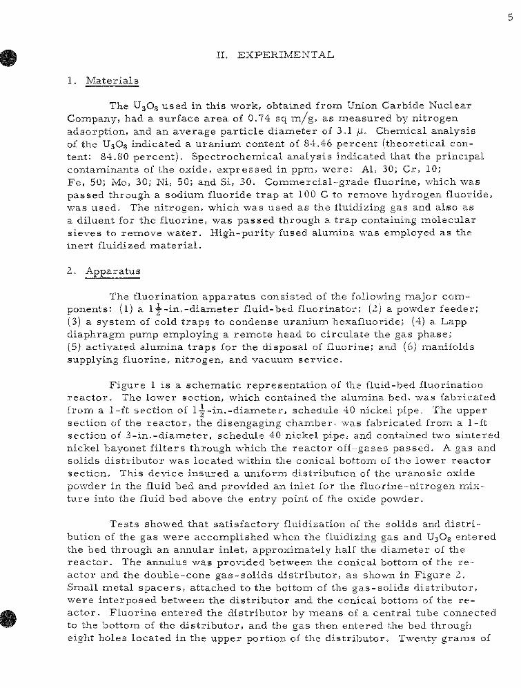
The UsOg used in this work, obtained from Union Carbide Nuclear Company, had a surface a r ea of 0.74 sq mi/g, as measured by ni trogen adsorption, and an average par t ic le d iameter of 3.1 /i. Chemical analysis of the UsOg indicated a uranium content of 84.46 percent ( theoretical content: 84.80 percen t ) . Spectrochemical analysis indicated that the principal contaminants of the oxide, expressed in ppm, were : Al, 30; Cr, 10; Fe , 50; Mo, 30; Ni, 50; and Si, 30. Commerc ia l -g rade fluorine, which was passed through a sodium fluoride t r ap at 100 C to remove hydrogen fluoride, was used. The ni trogen, which was used as the fluidizing gas and also as a diluent for the fluorine, was passed through a t rap containing molecular s ieves to remove wate r . High-puri ty fused alumina was employed as the iner t fluidized m a t e r i a l .
2. Apparatus
The fluorination appara tus consisted of the following major components: (l) a I j - i n . - d i a m e t e r fluid-bed fluorinator; (2) a powder feeder; (3) a sys tem of cold t r aps to condense uranium hexafluoride; (4) a Lapp diaphragm pump employing a r emote head to c i rcula te the gas phase; (5) act ivated alumina t r aps for the disposal of fluorine; and (6) manifolds supplying fluorine, nitrogen, and vacuum se rv ice .
F igure 1 is a schemat ic represen ta t ion of the fluid-bed fluorination r e a c t o r . The lower section, which contained the alumina bed, was fabricated from a 1-ft section of l y - i n . - d i a m e t e r , schedule 40 nickel pipe. The upper section of the r eac to r , the disengaging chaixiber, was fabricated from a 1-ft section of 3 - in . -d iamete r , schedule 40 nickel pipe.- and contained two sintered nickel bayonet f i l ters through which the reac to r off-gases passed . A gas and solids d is t r ibu tor was located within the conical bottom of the lower reac tor sect ion. This device insured a uniform distr ibution of the uranosic oxide powder in the fluid bed and provided an inlet for the f luorine-ni t rogen mixtu re into the fluid bed above the entry point of the oxide powder.
Tes ts showed that sa t is factory fluidization of the solids and d i s t r i bution of the gas were accomplished when the fluidizing gas and UsOg entered the bed through an annular inlet, approximately half the d iameter of the r e a c t o r . The annuius was provided between the conical bottom of the r e actor and the double-cone gas - so l ids d is t r ibutor , as shown in Figure 2. Small meta l s p a c e r s , at tached to the bottom of the gas -so l ids d is t r ibutor , were in terposed between the d is t r ibu tor and the conical bottom of the r e ac tor . F luor ine entered the d is t r ibutor by mieans of a cent ra l tube connected to the bottom of the d is t r ibu tor , and the gas then entered the bed through eight holes located in the upper port ion of the d is t r ibu tor . Twenty g r a m s of

6
p o w d e r , h a v i n g a n a v e r a g e p a r t i c l e d i a m e t e r of 6/1, c o u l d b e f ed in 1 m i n i n t o a 5 - i n . - h i g h a l u m i n a b e d c o m p o s e d of 60 m e s h p a r t i c l e s . T h e f l o w r a t e of the f l u i d i z i n g g a s w a s a p p r o x i m a t e l y 0 . 5 c f m a t r o o m t e m p e r a t u r e .
Figure 1
FLUID-BED FLUORINATION REACTOR
HIGH PRESSURE tgiTROGEN
METERING VALVE
AUTOMATIC BLOWBACK SOLENOID
VALVES
THERMOCOUPLE TO RECORDER
SINTERED MICKEL BAYONET FILTi
TO ACTIVATED ALUMINA TRAPS
Figure 2
GAS-SOLIDS DISTRIBUTOR FOR 1-1/2-IN. FLUIDIZED-BED REACTOR
THERMOCOUPLE WELL
THERMOCOUPLE TO CONTROLLER
RECORDER-
FLUIOIZING GAS(N2)
-U3OS
-GAS-SOLIDS DISTRIBUTOR CONE
•FLUORINATING GAS(Fg+N2)
CISrRlbU'OR
STR^BS
w SCALE
ONE IKCH
^•LUORINE
108-6288
T h e r e a c t o r w a s h e a t e d b y a r e s i s t a n c e f u r n a c e w h i c h h a d t h r e e h e a t i n g e l e m e n t s . T h e t w o l o w e r e l e m e n t s w e r e c o n t r o l l e d b y a t h e r m o c o u p l e i n s i d e t h e r e a c t o r a t t h e l e v e l of t h e f l u o r i n e i n l e t , w h e r e a s t h e u p p e r e l e m e n t w a s c o n t r o l l e d b y a t h e r m o c o u p l e p l a c e d a t a b o u t t h e m i d d l e of t h e o u t s i d e s u r f a c e of t h e r e a c t o r .
A n a u t o m a t i c b l o w b a c k s y s t e m , d e s c r i b e d b y L o a d i n g e t a l . . l - ' ) w a s e m p l o y e d t o r e t u r n s o l i d s w h i c h r e a c h e d a n d w e r e r e t a i n e d o n t h e s u r f a c e of t h e s i n t e r e d n i c k e l f i l t e r s . A V e n t u r i t h r o a t a n d j e t w e r e u s e d in t h i s s y s t e m to d e l i v e r a h i g h - s p e e d f l o w of n i t r o g e n t h r o u g h t h e b a y o n e t f i l t e r c o u n t e r c u r r e n t l y t o t h e n o r m a l g a s f l o w of t h e s y s t e m . S i n c e t h e b l o w b a c k p r o c e d u r e w a s a l t e r n a t e d b e t w e e n t h e t w o f i l t e r s , n o i n t e r f e r e n c e w i t h t h e n o r m a l f low of t h e r e a c t i o n g a s e s r e s u l t e d .

The co ld- t rap sys tem used to condense the uranium hexafluoride consisted of th ree t raps in s e r i e s . The t raps were refr igerated at about -80 C by use of a carbon dioxide-tr ichloroethylene slush. The t r aps were 4 in. in diameter and 1 ft in length. In the second and third t r aps a sintered nickel bayonet filter was placed on the outlet line of the gas s t r eam to r e tain any par t iculate m a t t e r . A t r a p packed with sodium fluoride was placed in se r i e s after the cold t r a p s . This t r ap , which was heated to 100 C, sorbed any uranium hexafluoride that had not condensed in the cold t r a p s .
Figure 3
POWDER FEEDER FOR FLUIDIZED-BED REACTOR
MOTOR-DRIVE
LCADiMG CORT'
RECPROCATlNG ROD
PRESSURE EQUILIBRAT NO Li^E
RECIPROCATII G P L J G
S,GHT PORT—
ESSURE GAUGE
TO THE FLUIDIZED__BED /
A powder feeder, shown in Figure 3, was developed as a means of feeding the U3O8 powder into the fluidizing-gas l ine. The body of the feeder, containing the uranosic oxide, was a hollow cylinder with a conical bottom. A conical plug was given a reciprocat ing up-and-down motion by means of a rod which passed through a bellows on the cover of the container and was attached to an ec centr ic shaft of a var iab le -speed motor . The powder re leased by the reciprocat ing plug dropped into the gas s t r eam and was injected into the fluidized bed as shown in Figure 1. Tests showed that the feeder could provide feed ra tes in the range be tween 2 and 20 g/min when the diameter of the par t ic les of U3O8 was 6 / i .
MITROGEN The Lapp d i a p h r a g m pump , 108-6287 u s e d to r e c i r c u l a t e the f luo r ine , had
a r a t e d flow c a p a c i t y of 0.5 cfm at a d i s c h a r g e p r e s s u r e of 15 ps ig and a t m o s p h e r i c p r e s s u r e i n t a k e . The r e m o t e h e a d of the pumip i s c o n s t r u c t e d of Monel and n icke l on the gas p u m p ing s ide , and the i m p u l s e i s t r a n s m i t t e d f r o m the c o m p r e s s i o n head by mieans of a t r a n s m i s s i o n l ine f i l led wi th f luoro lube o i l . M e a s u r e m e n t s of flow r a t e w e r e m a d e by i n e a n s of a t h e r m a l f l o w m e t e r of the type d e s c r i b e d by R. K e s s i e . ( 4 ) F low c a l i b r a t i o n of the pumip-f lowmeter c o m b i n a t i o n was a c c o m p l i s h e d wi th n i t r o g e n u s i n g a wet t e s t m e t e r .
3. P r o c e d u r e
The f l u o r i n a t i o n s of UsOg w e r e p e r f o r m e d in two r e a c t i o n p e r i o d s . In the f i r s t p e r i o d , which wil l be r e f e r r e d to a s the f eed ing - f luo r ina t i on p e r i o d , the UsOg powder w a s in j ec t ed into the fluid bed , and the m a j o r p a r t

of the oxide was converted to uranium hexafluoride by means of a gas miixtu re of 20 v /o fluorine in ni t rogen. In the second period, which will be r e f e r r ed to as the recycle-f luor inat ion period, the fluorine content was ra i sed to about 100 percent , and the gas recyc led through the Lapp pump and back to the fluidized bed. The l a s t t r a c e s of uranium were removed during the recycle-f luor inat ion per iod. In future exper iments with uranium dioxide-plutonium dioxide solid solutions, this step will se rve to remove the plutonium from the bed m a t e r i a l .
The general operat ing procedure for the fluorinations was as follows: About 400 to 500 g of 120 mesh fused alumiina was placed in the fluid bed fluorinator and was then heated to the operating t empera tu re of 500 C. During the heating period the ni t rogen flow needed to fluidize the bed was s ta r ted . The fluidizing ni t rogen entered the bottom of the r eac to r as shown m Figure 1. A charge of a mix ture of U3O8 and alumina in a 2:1 weight ra t io •was placed in the powder feeder . Alumiina was mixed with the U3O8 to improve the flow c h a r a c t e r i s t i c s of the oxide powder. When the reac tor reached the proper operat ing t empe ra tu r e the fluorine flow was s tar ted into the bed through the gas d is t r ibutor cone. The fluorine, which was 20 v /o of the total flow, was diluted with an equal quantity of ni trogen before it entered the bed. The UsOg alumina mixture was then introduced into the fluidizing ni trogen s t r e a m and thence into the fluid bed at a ra te of about 3 g of U3O8 per minute . The gas velocity in the Y-in.-diamieter fluidizing ni trogen inlet line into which the U3O8 is fed was 5 f t / s e c . Total flow ra te through the fluid bed was 12 l i t e r s / m i n , with the fluidizing nitrogen cont r ibuting approximately 7 l i t e r s / m i n , and the mixture of fluorine and ni trogen approximately 5 l i t e r s / m i n . The superficial velocity in the fluid bed was about 0.6 f t / sec at room t e m p e r a t u r e .
The effluent gas s t r e a m from the f luorinator , when the gas is not r ec i rcu la ted , passed through cold t r a p s and a sodium fluoride t r a p in o rder to remove the uranium hexafluoride, and then through an activated alumina t r a p which r eac t s with and removes excess fluorine. The effluent was then exhausted to the a tmosphe re . This once-through flow was continued while the U30g-alumina mixture was being fed into the fluid bed. In the cases in which no recycle was used, the once-through flow was continued for -j hr after the feeding was completed.
Following the feeding-fluorination period, the fluorine content of the gas phase was brought to approximately 100 percent and the recycle period was s t a r t ed . The recyc le flow was c a r r i e d out for a period of 5 h r . After the react ion per iod had been coinpleted, the sodium fluoride t r ap and the cold t r aps , which were maintained at -78 C, were evacuated to r e move the res idua l gas phase . The t r aps were then warmed to room t e m p e r a t u r e and weighed to a s say the amount of uraniumi hexafluoride collected. The fluid-bed alumiina was removed from the reac to r and sampled for u ran i um ana lys i s . The smal l amount of inixture of UsOg and alumina which was re ta ined in the disengaging section was removed and submitted for uranium ana lys i s .

9
III. RESULTS AND DISCUSSION
In the f irs t s e r i e s of exper iments , the pa rame te r s affecting the elutr iat ion of UsOg from the alumina bed were explored. The elutriat ion of UjOg from the alumina bed resu l t s in the deposition of solids containing uranium on the surfaces of the disengaging chamber and f i l ters , where no fliiorination of the UjOg occur s . For these exper iments , the bayonet fi l ters were removed from the disengaging chamber , and the solids which passed through the disengaging chamber were trapped in a filter that was placed in a separa te outside chamber of the r eac to r . By weighing the filter before and after the exper iment , the quantity of unreacted U3O8 and alumina elutr iated from the fluid bed could be determined. A determination of the quantity of UsOg elutr ia ted was made by dissolving the UsOg in the elutriated solids with ni t r ic acid. The residual alumina was then dried and weighed, the weight of UjOg being obtained by differences.
The resu l t s obtained in exper iments in which the part ic le size of the alumina, the bed height, and fluorine concentration were varied a r e shown in Table 1. When the par t ic le size of the alumina was decreased from 60 to 120 mesh, elutr iat ion of U3O8 from the bed was reduced from 19.5 to 9.0 percent of the U3O8 fed to the bed. When a 50-50 mixture of bO and 120 mesh alumina was used, the amount of U3O8 elutr iated was not appreciably l ess than the amount elutr iated when 60 mesh alumina was used.
T , . 1 J 1 I 1
E X P E K I M E X I A L f O X D I I I O N ' b A F F L C TING E L U I i U A r i O K O F UjOg F R O i M A F L U I D I Z E D B L D D U R I f l G F L L O R I N A I I O N
E x p t - r i m < u l d l C o n d i l i t i i i s
F l i i i f i - b e d A l u n u u a :
U3O8: F f f f i Ra t . - UsOfc B e d I e m p . ' r a i a r t : T o t a l Gar, F l o n R a t e ' F , • Nj) :
S u p e r f i c i d i FhiitiizAn^ G a s V<4ij
G a b V e l o c i t y m
R e a c t i o n P a x * a m e l e r
V a f i e d
\ l 2 O 3 iMesh Size-
B e d H e i g h t
F l u o r i n e C o n c e n t r a t i o n
• | - - i n . - d i a F e e d
A l , 0 3 P a r t i c l e S i z e
f m e toll)
l i O
60 bO . 120a
IZO
12(1 120 120 IZO
12U
520 100
A p p
hon
d.
a r o x . i g n u n
C
12 l i t t
e i t v : l . b L i n e : 5 ft
B e d
H e i g h t
(in.^
8
•6
a 4
b
12
8 8
8
ft r& m m
s e c dt 500 s e c a t 25 C
F7 C o n e
in G a s
( v / o l
20
20
20
20
20 20
10 20
30
C
P e r c e n t
E l u t r i e i t i o n
of U3O8
9.0
1 9 . 5 1 9 . 0
2 3 . 0
9 .0
9 .5 2 9 . 0
9 .0 5 .7
" ' M i x t u r e : 50 \v o 60 m e ^ h a l u m i n a t 50 \\ o 120 m e s h a l u m i n a .

10
Variat ion of the height of the alumina bed also affected the amiount of UaOg elutr ia ted from the bed. Increas ing the bed height from 4 to 8 in. reduced the amount of U3O8 elutr ia ted from 23 to 9 percent of the quantity of U3O8 charged to the bed, as shown by the r e su l t s l is ted in Table 1. F u r ther inc rease in bed height, however, did not resu l t in a further reduction in the amount of U3O3 elut r ia ted from the bed.
The amount of UsOg elutr ia ted from the fluid bed was found to de c r e a s e as the concentrat ion of fluorine in the reac tant gas was inc reased . As shown in Table 1, the concentrat ions of fluorine used were 10, 20, and 30 v / o . With these gas mix tu re s , the amounts of UsOg elutr iated were 29, 9.0, and 5.7 percent , respect ive ly , of the amount of U3O8 originally p resen t . F r o m these data, it is apparent that the elutr iat ion of UsOg from the fluid bed will d e c r e a s e with decreas ing par t ic le size of the alumina, increas ing bed height, and increas ing concentrat ion of fluorine.
In a second s e r i e s of exper iments , the effect of t empera tu re on the fluorination of UsOg to uranium hexafluoride was examined. The bayonet f i l ters were r e in se r t ed in the disengaging chamber , and each filter was subjected to a blowback with ni t rogen every 5 miin during the exper iment . As in the ea r l i e r exper iments , gas recycle was used except during the feeding-fluorination period. Table 2 l i s t s the data obtained for exper iments per formed at 450, 500, and 550 C. The percentages of U3O8 converted to uranium hexafluoride were 92 percen t at 450 C, 97.6 percent at 500 C, and 98.5 percent at 550 C.
Table 2
E F F E C T OF TEMPERATURE ON THE FLUID-BED FLUORINATION OF U3O8
Exper imenta l Conditions
Fluid-bed Alumina: 470 g (120 mesh) Feed Mater ia l : 100 g UsOg (325 mesh) ,
50 g AI2O3 (120 mesh) Total Gas Flow Rate (F2 + N2): 12 l i t e r s / m i n at 25 C Superficial Fluidizing Gas Velocity: 1.6 f t /sec at 500 C Gas A^elocity in -|--in.-dia Feed Line: 5 f t / sec at 25 C F i l t e r s a l te rna te ly blown back every 5 min. Fluor inat ion continued for -j- h r after feeding-fluorination
step completed.
U308 Feed Rate
(g/min)
2.4 3.6 2.4
Bed Tempera tu re
(C)
450 500 550
% Conversion of U3O8 to UFe Based on UFg Collected
92.0 97.6 98.5

11
A final s e r i e s of exper iments was performed at 500 C in which a 5-hr recycle period with 100 percent fluorine and an automatic blowback system were employed. During the recycle period, the portion of the feed line immediate ly adjacent to the reac tor was heated to 450 C to facilitate the fluorination of any UjOg which might have remained in this a rea . The experimental conditions used and the resu l t s obtained in these experiments a r e l is ted in Table 3. The data show that 99 percent or more of the UjOg can be converted to uranium hexafluoride by means of a fluid-bed fluorination under the react ion conditions used in these exper iments . In one exper iment , the 5-hr cycle period was performed at a t empera tu re of 550 C;
Table 3
FLUID-BED FLUORINATION OF UjOg
Exper imenta l Conditions
F lu id-bed Alumina:
Uranos ic Oxide-Al203 Feed Mixture:
Feed ing-F luor ina t ion Per iod : Bed T e m p e r a t u r e : Total Gas Flow Rate (at 25 C):
Fluidizing N2 Fluor ine N^ in F luor ine
Superficial Fluidizing Gas Velocity: Gas Velocity in -g-in.-dia Feed Line:
Recycle Per iod:
120 mesh , 420 g
300 g U3O8; 150 g Al^Oi
500 C 12 l i t e r s / m i n 7 l i t e r s / m i n 2.5 l i t e r s / m m 2.5 l i t e r s 'min 1.6 f t / sec at 500 C 5 f t / sec at 25 C
U308 Feed Rate
(g/min)
3.7 3.7 2 .5 3.5 5.1c 4 .1 4 .6 6.0
5.9 3.8
Ga
Bed Temp Total Gas
e r a t u r e : Flow Rate:
F luor ine Gone in Gas Recycle T i m c T e m p e r a t u r e
Cone in s Phase
during Recycle (v/o)
100 100 100 100 100 100 100 100
50 50
of Feed
P h ase :
Line
Analytical
Total Residual
U
(g!
0.26 0.37 0.77 2.28 0.13 0.63 0.82 0.99 0.57 0.60
-
Resul ts
U in
B e d
(g]
0.12 0.24 0.09 0.26 0.07 0.24 0.09 0.30 0.39 0.11
500 C 8 l i t e r s / m i n 100 percen t 5 hr 450 C
% UjOg Converted to UF^ Based
U3O8 Residue^ Unreacted
99.7 99.9 99.8 99.5
100 99.8 99.7 99.6 99.7 99.7
on
UFe Collected
99.8 98.9 99.0 98.5
101 97.6
100 99.5 99.2 99.1
Mate r i a l^ Balance
(%i
100.1 99.0 99.2 99.0
101 97.8
100.3 99.9 99.5 99.4
^Mate r ia l re ta ined in disengaging chainber and r ep resen ta t ive sample of bed m a t e r i a l analyzed for u ran ium content, and the total u ran ium content f rom both of these sou rces used to ca lcula te the pe rcen t convers ion .
'^Material Balance % = % conver ted (UF5 base) i [100 - % converted (Anal base ) ] .
"-Bed t e m p e r a t u r e during recyc le f luorination period; 550 C.

at this t empe ra tu r e essent ia l ly complete conversion of the UjOg to uranium hexafluoride was achieved. In two exper iments the gas phase during the recycle-f luor inat ion period contained 50 v /o fluorine. The con-version obtained in these exper iments was essent ia l ly the samie as that achieved in exper iments with 100 percent f luorine.
The higher values of conversion l is ted under Column 5 in Table 3 a r e based on the r e su l t s of analyses for uranium of representa t ive samples of the bed ma te r i a l and the ma te r i a l deposited in the disengaging chamber . Uranium retent ion in the alumina beds ranged from 0.02 to 0.05 w/o , c o r responding to 0.1 to 0.3 g of uranium for total weights of the recovered alumina beds of from 518 to 572 g. The disengaging chamber samples , which ranged in weight fromi 1 to 3 g, contained from 0.1 to 1.0 g of u ran ium. The total uranium contents of the alumiina beds and disengaging chamber samples r ep resen ted 0.1 to 0.5 percent of the uranium fed to the r eac to r The miate-r i a l balance f igures were calculated from the percent conversion figures based on uran ium hexafluoride collected and the analyses of the bed and d i s engaging chamber ma te r i a l as follows.
Mater ia l Balance % = foCUF^base) + [100 - % (Anal base) ] .
The somewhat lower conversion f igures based on uranium hexafluoride collected a r e apparent ly not due to loss of hexafluoride, since the quantities found on the sodiuin fluoride were well below the tested capacity of the t r ap It is probable that the d iscrepancy is due to weighing inaccurac ies .
The r e su l t s obtained in this work showed that g rea te r than 99 p e r cent of the 100 g of UsOg powder fed to a fluid bed under the react ion conditions used in this study can be converted to uranium hexafluoride. The exper imenta l conditions (shown in Table 3) which were developed during the course of this study will se rve as the initial react ion conditions for future work m which mix tu res of U3O8 and plutoniumi dioxide will be fluorinated.
The high conversions to uranium hexafluoride and the small amounts of U3O8 found in the disengaging chamber of the reac tor indicate that the U3O8 mus t be reac ted in the na r row zone in which the U3O8 and fluorine mix. That U3O8 reac t s rapidly with fluorine was shown by kinetic exper iments per formed over the t empe ra tu r e range from 300 to 400 C (see Appendix B), A react ion ra t e of 0.02 g of U3O8 per minute at 400 C was obtained. F r o m the extrapolated react ion ra te at 500 C, a react ion t ime for a par t ic le of U3O8 of 1.7 miin was calculated. An estiixiate made of the res idence t ime of a par t ic le 12/i in d iamete r in a fluid bed at a superficial gas velocity of 0 67 f t / sec is 24 min.'-^/ Therefore , the par t ic les should be reac ted completely in the bed, and the conversion obtained in this work tend to substantiate th is conclusion.

IV. APPENDIX A
Oxidative Decladding of Stainless Steel-c lad and Z i rca loy-c lad Uranium Dioxide Pel le ts
Removal of u ran ium dioxide and plutonium dioxide from s ta inless s teel cladding by oxidation of the u ran ium dioxide to U3O8 is being cons idered as a step which would precede fluorination in a fluid-bed fluoride volatili ty p r o c e s s . Oxidation of u ran ium dioxide pellets r esu l t s in an inc r e a s e in volume and pulverizat ion of the pellets as U3O8 is formed. The feasibil i ty of the p r o c e s s was demons t ra ted at Atomics Internat ionals '° / where successful decladding of u ran ium dioxide pellets clad in Type 304 s ta in less s teel was achieved by oxidation at 400 to 500 C with air or oxygen. In these exper iments , in which g rea te r than 99 percent of the u ran ium dioxide was removed from the cladding by oxidation, holes were punched through the cladding at shor t in tervals along the length of the fuel e lements . This p rocedure r e su l t ed in the rupture of the cladding during oxidation, thus allowing g rea t e r access of the oxidizing gas to the uranium dioxide pe l le ts . The IJ^Og was sepa ra ted from the cladding by mildly vi brat ing the a s sembl i e s .
In Appendix A, the oxidative decladding of uranium dioxide fuel e lements in a fluid-bed r eac to r is d iscussed. The oxidative decladding step not only s e rves to separa te u ran ium and plutonium oxides from the cladding ma te r i a l , but also se rves to produce a uniform feed for the f luidized-bed f luorinator . F luor inat ion of spent uranium dioxide r eac to r fuel containing c racked and fragmented pellets r e su l t s in uneven fluorination conditions if the fluorination is not preceded by oxidation. If oxidation does precede fluorination, finely divided U3O8 powder with an average par t ic le size of 10 /i and surface a r e a s of 0.5-1.0 sq m / g is producedj and the subsequent fluorination proceeds smoothly.
Introduction of the powdered U30g to the fluid bed fluorinator can be achieved by e i ther of two methods . In one procedure , a section of the spent fuel e lements is oxidized and declad in the lower section of the fluid-bed r eac to r , and the U30g and plutonium oxide powders a re t r a n s por ted into the upper section of the fluid bed, where they are fluorinated. In an a l ternat ive p rocedure , the oxidized mixture of uranium and plutonium oxides a re mechanical ly fed to the fluid-bed r eac to r .
P r e l i m i n a r y exper iments in a horizontal tube furnace with ™--in.-long fuel sections which contained UOg pellets clad in Type 304 s ta inless s tee l tubing (wall th ickness , 20 mi ls) showed the following r e s u l t s :
a) Conaplete convers ion of UO2 to UsOg occu r r ed in 3 to 4 hr at t e m p e r a t u r e s between 450 C and 550 C in a flowing s t r e a m of a i r ; finely divided, freely flowing oxide powders were produced.
14
b) The oxidized ma te r i a l could easily be removed from the cladding tube by gentle vibrat ion of the fuel e lements .
c) Although oxidation is slightly faster at t empera tu res of 450 or 550 C in a s t r e a m of pure oxygen, the ma te r i a l has a tendency to cake and stick to the cladding.
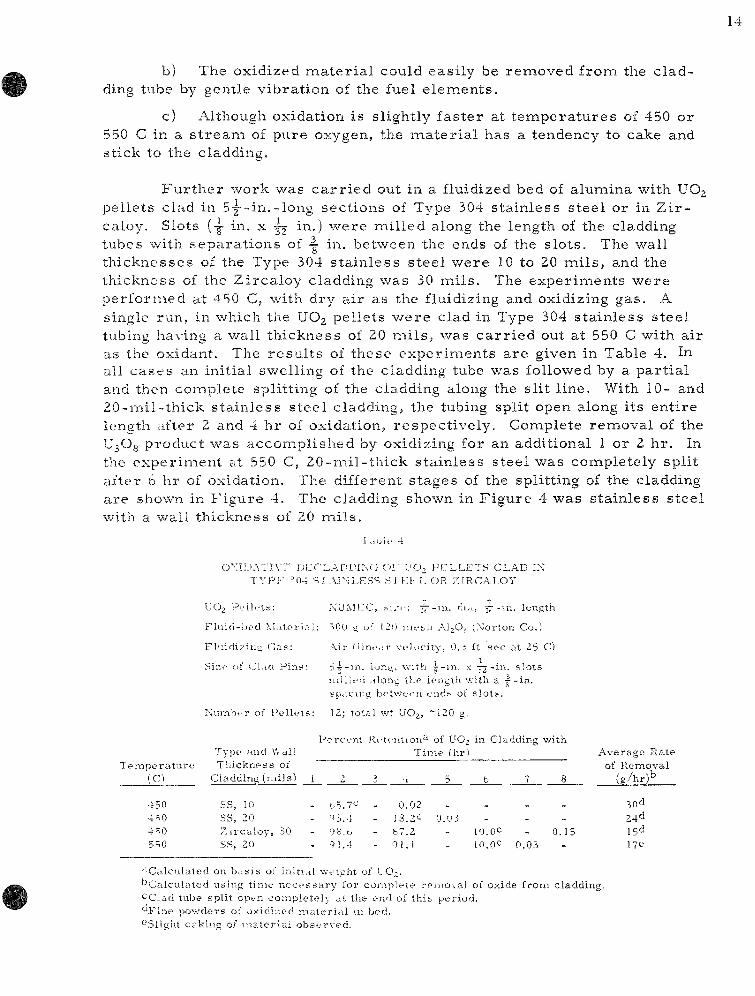
F u r t h e r work was c a r r i e d out in a fluidized bed of alumina with UO2 pellets clad in 5-|--in.-long sections of Type 304 stainless s teel or in Z i r caloy. Slots (-g- in. X J2, i"") were mil led along the length of the cladding tubes with separat ions of ~ in. between the ends of the s lots . The wall thicknesses of the Type 304 s ta inless s teel were 10 to 20 mi l s , and the thickness of the Zircaloy cladding was 30 mi ls . The experiments were performed at 450 C, with dry air as the fluidizing and oxidizing gas. A single run, in which the UOg pellets were clad in Type 304 s ta inless s teel tubing having a. wall thickness of 20 mi l s , was ca r r i ed out at 550 C with air as the oxidant. The resu l t s of these exper iments are given in Table 4. In-all cases an initial swelling of the cladding tube was followed by a par t ia l and then complete splitting of the cladding along the slit l ine. With 10- and 20-mil - th ick s ta in less steel cladding, the tubing split open along its entire length after 2 and 4 hr of oxidation, respect ively. Complete removal of the U3O3 product was accomplished by oxidizing for an additional 1 or 2 hr . In the exper iment at 550 C, 20-mil - th ick s tainless steel was completely split after 6 hr of oxidation. The different stages of the splitting of the cladding are shown in F igure 4. The cladding shown in Figure 4 was s tainless steel with a wall thickness of 20 mi l s .
l a b l e 4
OXlI . iATlVr DLTLALDIXG C)I' "JO, P E L L E T S CLAD IX T Y P F =.04 •=; 1 .YIXLESS SI HI- L OR ZIRCALOY
LIOj P e l l e t s : K-UMLC, ^-..'i-: i t - m - "''>' ^ " i n . length
F l u i d - b e d iMater ini : 500 y of IZO nie.^:i A i p , sN'ortor. Co.)
Fh i id iz iu i ; G a s : Air ("line.ir ve loc i ty , O.s ft sec at 25 C)
Sizf of CLici P i n s : S j - m . lur.y, v.-.t'n | - - in . x -j^-in- s l o t s n i i i l ed .dong the lengtli v.dth a - f - in . spac ing b e t w e e n ends of s l o t s .
N u m b e r of P e l l e t s : 12; to ta l wt UO, , ~120 g.
P e r c e n t Retention'- ' of UO^ in Cladding wi th
T e m p e r a t u r e (C)
450 4^0 4'^0 5=;o
Type and \",Lill T h i c k n e s s of
Cladding ( n d l s )
SS, 10 SS, 20 Z i r c a l o y , 30 SS, 20
1 2
b5.7c' - '^3.4 - 9B.b - 91.4
3
---
Ti
•1
0.02 18.2C b7.2 <?!.!
l ie !hr1
5
0.U3 --
6
-10.0*^ 10.Q*^
1
~ -
0.03
8
-0.15
-
A v e r a g e R a t e of R e m o v a l
( g / h r ) ^
30d 24"^ 15° 17C
••-Calculated on b . ts is of initiftl we igh t of UO,. " C a l c u l a t e d us ing t i m e n e c e s s a r y for c o m p l e t e r e m o v a l of oxide f rom c ladd ing . '^Clad tube sp l i t open c o m p l e t e l y at the end of t h i s p e r i o d . ° F i n e p o w d e r s of ox id ized mater i<i l m bed. •-'Slight cak ing of m a t e r i a l o b s e r v e d .

15
H
l-lgiire 1
PHOTOoR>i'H SHOWING TYPE ?o i ST \IN-LESS STEEL-CL\D UR,\NIUM DKLXIDE
1 UEL EI EMENTS AFTER V \RIOUS ST\GFs 0¥ CXIDATIthN
\ -Cnmnal Element, 2o-inil-thick T\pe ^04 slaiuksis. bts-el cLiJdiiis:;.
B -Ciaddms; altir 2 hr t f oxid ition. C -Cldddmg afttr 4 hr ot oxiditiou. D -Ciaddiiig aft^r T hr ot oxiditiou.
* - ^ S C A L E - nctieo
0 I t ' !
l i i b - > ; . '81
In F i g u r e 4, A i s the o r i g i n a l e l e m e n t , _B i s a s i m i l a r s p e c i m e n af ter 2 h r of ox ida t ion , C i s a s p e c i m e n af ter 4 h r of oxidti t ion, and D is a b p e c i m e n af ter 5 h r of ox ida t ion and c o m p l e t e r c n i o \ a l of the u r a n o s i c oxide pov/der . S e v e r a l o b s e r v a t i o n s can be m a d e f rom the r e s u l t s of t h e s e e x p e r i m e n t s :
1) Oxida t ive dec ladd ing of u r a n i u m dioxide pe l l e t s c lad in Type 304 s t a i n l e s s s t e e l o r Z i r c a l o y is f e a s i b l e m a fluid bed at 450 C, wi th a i r a s the ox idan t .
2) Mi l l ing s l o t s a long the l eng th of the c ladding a l lows g r e a t e r a c c e s s of the ox id iz ing gas to the p e l l e t s , p r o m o t e s sp l i t t ing of the c l a d ding a long the s lo t l ine , and m a k e s e a s i e r the r e m o v a l of U30g f r o m the c l add ing .
3) The t i m e n e c e s s a r y for c o m p l e t e r e n i o \ a l of the U30g fo rn i ed a p p e a r s to be dependen t on the t i m e n e c e s s a r y to ach i eve c o m p l e t e sp l i t t ing of the c l add ing , which in t u r n a p p e a r s to be dependen t on the t h i c k n e s s of the c l add ing .

V. APPENDIX B
The Kinet ics of the Fluor inat ion of Uranosic Oxide
The oxidative decladding of uraniumi dioxide fuel e lements will p r o duce finely divided, powdered U3O8. In the fluid-bed fluoride volatility p r o c e s s , the U3O8 will be fluorinated in a fluid-bed reac to r . The U3O8 will e i ther be produced in the same fluid bed in which the fluorination will be c a r r i e d out, or p r epa red in a separa te react ion vesse l and injected into the fluid bed of a f luorinator . It is nece s sa ry that the U3O8 be fluorinated during i ts res idence t ime in the fluid-bed medium, in o rde r to minimize e lut r ia t ion of the U3O8 powder to cooler portions of the r eac to r , where r e action would not take place. A study of the kinetics of the react ion of fluorine with U3O8 was made in o rde r to obtain information from which the res idence t ime neces sa ry to completely r eac t a par t ic le of U3O8 with fluorine in a fluid bed could be calculated.
Two batches of U3O8 were used in this study. The f i rs t , p r epa red by the New Brunswick Labora tory of the AEC and designated as NB-15,had a cer t i f ied puri ty of 99.9+ percent . The second batch, p r epa red by Union Carbide Nuclear Corporat ion and designated as UCN, had a uranium content of 84.99 percen t ( theoret ical for U3O8, 84.80). The surface a r e a s , as mieasured by ni t rogen adsorption of the NB-15 and UCN source m a t e r i a l s were 0.14 and 0.28 sq mi/g, respec t ive ly . The fluorine used was commier-cial grade f rom which hydrogen fluoride was removed by passing the gas through a t r ap filled with sodium fluoride heated to 100 C.
The fluorination exper iments were performed with a thermobaiance that was specially designed for use with fluorine. The main components of this thermobaiance , which has been descr ibed in detail by Johnson and Fischer,C^) a re a Sar to r ius Selecta analytical balance, equipped for automatic weight record ing , and a ve r t i ca l , tubular react ion chamber . A nickel sample pan, upon which the U3O8 powder •was placed, "was suspended in the reac t ion chamber by a Monel chain at tached to the s t i r rup of the Sar tor ius balance. F luor ine was passed through a p rehea te r before the gas entered the r eac to r . The flo'w ra t e of the fluorine was m e a s u r e d by a t he rma l flo^w-me te r . A thermocouple positioned direct ly beneath the sample pan sensed the react ion t e m p e r a t u r e . The output of the thermocouple was m e a s u r e d with a Rubicon Type B potent iometer . A multipoint recording potentiona-e te r was used to monitor the t e m p e r a t u r e of the furnace used for p rehea t ing the gas , the t empera tu re of the reac t ion furnace, and the output of the t h e r m a l f lowmeter .
In a typical exper iment , 400 mig of U3O8 were placed on a t a r ed nickel pan and then lowered into the reac t ion chamber which was preheated to the des i red t e m p e r a t u r e . During this stage of the exper iment , a flow of nitrogen was mainta in ted through the r eac to r . The weight of the oxide sample was checked on the Sar to r ius balance while t empera tu re equi l ibr ium between gas
17
and solid was being attained. When the react ion system had reached a uniform t e m p e r a t u r e , the flow of ni trogen was stopped and a flow of fluorine at a ra te of 150 c c / m i n was s ta r ted . The weight change of the oxide sample v e r s u s reac t ion t ime was continuously r ecorded during the react ion period.
The data obtained in these exper iments were co r re l a t ed by use of the d iminish ing-sphere model. This t r ea tmen t of the data has been discussed in detail by Johnson. \ ' ' ' Briefly, in the model it is assumed that in the g a s -solid react ion, the solid reac tan t consis ts of spher ical par t ic les of uniform d iameter , and that the reac t ion occurs uniformly on all the par t ic les s imul taneously, when the layer of solid is thin enough to allow saturat ion with the reac tan t gas . The reac t ion ra te is then a function of the surface a rea of the par t i c le . A mathemat ica l t r ea tmen t was developed for this kinetic model based on a gas - so l id react ion occurr ing at a continuously diminishing spher ical interface. In the final express ion, the react ion ra te is re la ted to the fraction of unreac ted solid as shown in the following equation:
(1 _F)i/3 = 1 . k ' t , (1)
in which
F = the fraction of solid reac ted;
k' = k / roP J where r^ is the init ial radius of a par t ic le , and p is the bulk density;
t = reac t ion t ime in minutes .
A plot of the function (l - F) ve r sus t r e su l t s in a s t ra ight line and the reac t ion ra te constant can be obtained from the slope of the l ine.
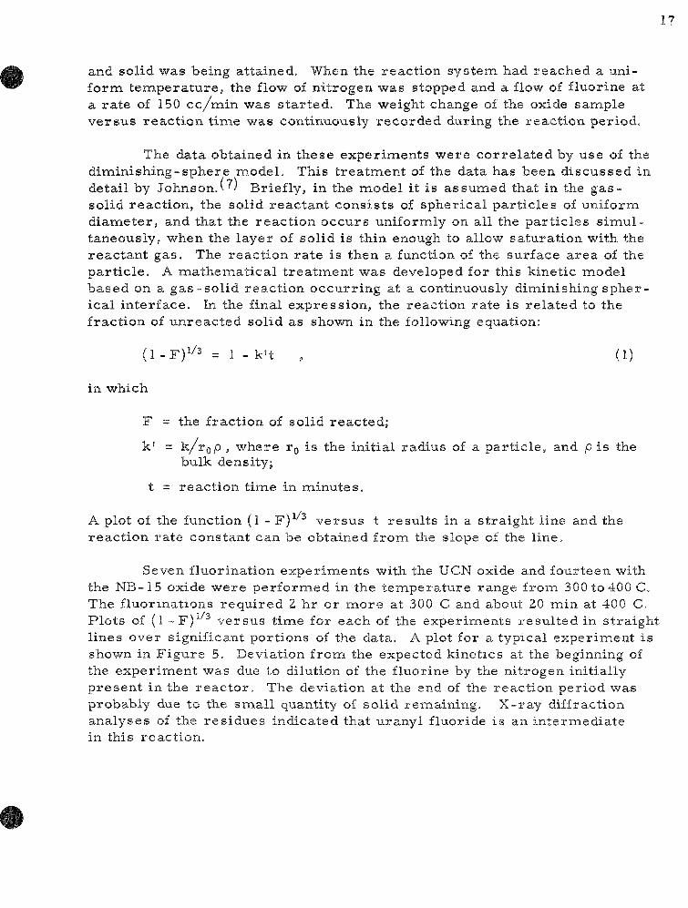
Seven fluorination exper iments with the UCN oxide and fourteen with the NB-15 oxide were per formed in the t empera tu re range from 300 to 400 C, The fluorinations requ i red 2 hr or more at 300 C and about 20 min at 400 C. Plots of (1 - F) ve r sus t ime for each of the exper iments resu l ted in s t ra ight lines over significant portions of the data. A plot for a typical exper iment is shown in F igure 5. Deviation from the expected kinetics at the beginning of the exper iment was due to dilution of the fluorine by the nitrogen initially p resen t in the r eac to r . The deviation at the end of the react ion per iod was probably due to the smal l quantity of solid remaining. X- ray diffraction analyses of the res idues indicated that uranyl fluoride is an in termedia te in this react ion.

18
Figure 5
FLUORINATION OF UjOg
Tempera tu r e : 401 C Fluorine Flow Rate: 120 ml /min U3O8 Mesh Frac t ion : -100 +325
TIME, f,min
Rate constants were calculated from the slopes of the plots of the function (l -F)^''^ ve rsus t ime in minutes . The variat ion of these rate cons tants , k' of Equation ( l) , with t empera tu re are shown in Figure 6 for exper iments performed with samples of UCN and NB-15 oxides. F r o m the slopes of the lines drawn through the two sets of data points, activation energies of 3 1 and 30 kca l /mole were calculated for the reactions between fluorine and NB-15 oxide and UCN oxide, respect ively. The somewhat l a rge r values of the react ion ra te constants obtained with the UCN samples of U3O8 is probably due to the l a rge r surface a rea of that mate r ia l . The in tegrated form of the Arrhenius equation was fitted to the data to obtain the following equations represen t ing the change in rate constant with t empe ra tu r e :
NB-15 oxide, log k' 6787
+ 8.4438 (2)
UCN oxide, log k' -6599
+ 8.3133 (3)

19
Figure 6
VARIATION OF RATE CONSTANT, k' (min"^), WITH TEMPERATURE FOR THE FLUORINATION OF UjOg
Tempera tu re Range; Rate Equation:
300-400 C (1 -F)i''2 = 1 . k ' t
50
"o 10 -
^ e
I
0.1 1.8
• UCN U3O8 O NB-15 U3O8
1.75 1.7 1.65 1.6 l /T XIO»(K)
1.55 1.5 1.45
By means of Equation (3), an extrapolated value of 0.6 miin"^ was calculated for the ra te constant at 500 C, the t empera ture for the fluid-bed fluorination of U3O8. To es t imate the time necessary completely to fluo-rinate a par t ic le of UsOg, the kinetic equation was used in the following form:
r ^ = k ' t (4)
in which
r = radius of the par t ic le at tinie t in the fluorination; ro = initial radius of the par t ic le .

When r is very smiall, that i s , when the par t ic le has been essent ial ly completely conver ted to uranium hexafluoride, then the tinae is equal to the r e c iprocal of the ra te constant The solution of Equation (4) for t, with the value for the extrapolated ra t e at 500 C, gave a value of 1.7 min. It has been calculated(5) that the res idence t ime of a 12-/i-diameter par t ic le in a fluid bed at a superficial gas velocity of 0.67 f t / sec would be 24 min. There fore, if the extrapolated ra t e constant is reasonably accura te , a res idence t ime which is seve ra l t imes g rea te r than is needed for coiTiplete react ion is available. The adequacy of the ra te constant can be deduced from the data for the fluid-bed fluorination of uranos ic oxide presented in another section of this r epo r t (see p. 9 ). In these exper iments , which were performed at 500 C and with a superf icial fluidizing gas velocity of 1.5 f t / s ec , more than 99 percent of the U3O8 was converted to uranium hexafluoride; the alumina fluid bed ma te r i a l contained not more than 0.05 w/o uranium.

VI. SUMMARY
In the conceptual flowsheet of the fluid-bed fluoride volatility p r o c e s s , the uran ium and plutonium contents of spent oxide fuels will be r ecove red by fluorination to produce the volatile hexafluorides of uranium and plutonium. Labora to ry - sca le work has been concerned with the f luorination of U3O8 in a l y - i n . - d i a m e t e r fluid-bed fluorinator, per formed to develop and t e s t apparatus and p rocedures for use in future work in which plutonium will be handled. The oxide U3O8 was used because it would be the major product obtained in an oxidative decladding step which has been proposed for the removal of uranium and plutonium from s ta inless s tee l -and Z i rca loy-c lad fuel e lements .
In the p re sen t t e s t s , the powdered U3O8 was injected into the fluid bed by means of a fluidizing ni trogen s t r eam. Fluorine was introduced into the fluid bed jus t above the point at which the po"wder entered the bed. Exper imenta l investigation of the effect of p a r a m e t e r s such as t empera tu re , U3O8 elut r ia t ion f rom the fluidized bed, and duration of the fluorination per iod upon the react ion. A scheme employing two fluorination periods at a t empera tu re of 500 C has been developed; during the f i r s t period, UsOg is fed into the fluid bed and fluorination is c a r r i e d out simultaneously with 20 v /o fluorine in the gas phase; during the second period, a gas phase containing 100 percent fluorine is r ec i r cu la t ed through the fluid bed for a per iod of 5 hr . By means of this reac t ion schemie, more then 99 percent of the U3O8 fed to the fluid-bed r eac to r was converted to uranium hexafluoride.
React ion r a t e s have been m e a s u r e d by means of a thermobaiance for the reac t ion of U3O8 with fluorine over the t empera tu re range from 300 to 400 C. Two samples of U3O8 were used; one was an analytical s tandard sample , the other was commiercially produced ma te r i a l . The data have been co r r e l a t ed by means of a d iminishing-sphere kinetic model which re la tes the react ion ra te constant to the fraction of unreac ted oxide. The react ion ra t e constants for the commerc ia l ly produced m a t e r i a l were slightly higher than those for the analytical s tandard sample at the same t e m p e r a t u r e s . An average value of 30 kca l /mo le has been calculated for the activation energy of the fluorination react ion which, within exper imental e r r o r , was found to be the same for the two miaterials tested. Equations relat ing the change in react ion ra te constant with temiperature were derived. An es t imate was made of the t ime r equ i r ed completely to convert a par t ic le of uranosic oxide having a d iameter of about 10 jJ. to uranium hexafluoride at 500 C. The e s t ima te , which was based on an extrapolated value of the ra te constant, r e sulted in a value of l ess than 2 min
Fuel-elemient mockups, which consis ted of 5 y-in.- long sections of | - - in . -diameter s ta in less s teel or Zircaloy tubing packed with uran ium dioxide pel le ts , were oxidized in a fluid bed at 450 C with air as the oxidant and fluidizing gas . Slots (--in. x ^ i n . ) were mil led along the length of the cladding tubes at 4-111. in terva ls between the ends of the slots to promote the

splitting of the cladding during oxidation. The t ime necessa ry to split open a section of cladding along the sli t line was dependent on the th icknesses of the tubing wall . In the case of s tainles s teel , tubes having wall thickness of 20 and 30 mi l s split open along their ent i re lengths after 2 and 4 hr of oxidation, respect ive ly . In the case of 30-mil - th ick Zircaloy, the tubing was completely split after 6 hr of oxidation. Complete remioval of the U3O8 product was accomplished by means of 1-2 hr of additional oxidation.
VII. ACKNOWLEDGMENT
The authors wish to acknowledge the contribution of R. W. Kess ie in the design and specification of the fluid-bed equipment used in this work.

VIII. BIBLIOGRAPHY
1. Jonke, A. A., F i s c h e r , J . , and Mecham, W. J. , F luor ide Volatility P roces s ing of Low-enr iched Fue l s , T rans . Am. Nucl. Soc. 4 , (1961).
2. J a r r y , R. L., et a l . , Labora tory Investigations in Support of Fluid-bed Fluor ide Volatility P r o c e s s . I. The Fluorinat ion of UOy.-PuO?. Solid Solutions, ANL-6742 (1963).
3. Loeding, J. W. ,_e ta l . , The Flu id-bed Calcination of Radioactive Wastes , ANL-6322.
4. Kess i e , R. W., The Design and Construction of Thermal F lowmete r s , ANL-6531.
5. Gabor, J., Chemical Engineer ing Division, Argonne National Laboratory, pr ivate communicat ion.
6. Guon, J . , et aJ., Low Decontamination Reprocess ing Studies on I r rad ia ted UO2 Reactor Fuel , NAA-SR-6136 (Dec 15, 1961).
7. Johnson, C , and F i s c h e r , J . , Kinetics of the Reaction of Sulfur T e t r a -fluoride with Uranium Trioxide and Uranyl F luor ide , J. Phys . Chem., 65, 1849 (1961).