annex a stress intensity factor (sif) solutions · a.1.3 general notes on api 579 k solutions in...
TRANSCRIPT

(01 May 2006) FITNET MK7
© FITNET 2006– All rights reserved A-1
Annex A
Stress intensity factor (SIF) solutions
A.1 Introduction.........................................................................................................................................2 A.1.1 General Notes on BS 7910 K Solutions.............................................................................................3 A.1.2 General notes on R6 K Solutions ......................................................................................................3 A.1.3 General Notes on API 579 K Solutions..............................................................................................4 A.2 Flat Plates............................................................................................................................................5 A.2.1 Central through-thickness Crack.......................................................................................................5 A.2.2 Surface Crack......................................................................................................................................8 A.2.2.1 Finite crack ..................................................................................................................................8 A.2.2.2 Extended crack..........................................................................................................................19 A.2.2.3 Extended double crack .............................................................................................................22 A.2.3 Embedded Crack...............................................................................................................................23 A.2.3.1 Finite crack ................................................................................................................................23 A.2.3.2 Extended crack..........................................................................................................................30 A.2.4 Edge Crack ........................................................................................................................................33 A.2.4.1 Single edge crack (tension) ......................................................................................................33 A.2.5 Double Edge Crack ...........................................................................................................................35 A.2.5.1 Finite plate .................................................................................................................................35 A.2.5.2 Infinite plate ...............................................................................................................................37 A.2.6 Corner Crack .....................................................................................................................................38 A.2.7 Corner Crack at a Hole (symmetric) ................................................................................................42 A.2.8 Corner Crack at a Hole (single)........................................................................................................47 A.3 Spheres..............................................................................................................................................48 A.3.1 Through-thickness Equatorial Crack...............................................................................................48 A.3.2 Surface Crack....................................................................................................................................53 A.3.3 Embedded Crack...............................................................................................................................55 A.4 Pipes or Cylinders ............................................................................................................................56 A.4.1 Pipes or Cylinders with Axial Cracks ..............................................................................................57 A.4.1.1 Through-thickness cracks ........................................................................................................57 A.4.1.2 Surface cracks...........................................................................................................................69 A.4.1.3 Embedded crack........................................................................................................................90 A.4.2 Pipes or Cylinders with Circumferential Cracks.............................................................................92 A.4.2.1 Through-thickness crack ..........................................................................................................92 A.4.2.2 Surface cracks.........................................................................................................................100 A.4.2.3 Embedded crack......................................................................................................................126 A.5 Cracks In Nozzles ...........................................................................................................................128 A.6 Welded joints...................................................................................................................................129 A.6.1 Butt, Full Penetration and Attachment Welds with Surface Crack at Weld Toe.........................129 A.6.1.1 Solutions based on 2D FEA....................................................................................................130 A.6.1.2 Solutions based on 3D FEA....................................................................................................130 A.6.2 Load Carrying Fillet or Partial Penetration Weld with Surface Crack at Weld Toe [A.49] .........136 A.6.3 Root Cracks in Cruciform Joints ...................................................................................................137 A.7 Round Bars and Bolts ....................................................................................................................139 A.7.1 Straight-fronted Crack in a Bar ......................................................................................................139 A.7.2 Semi-circular Surface Crack in a Bar ............................................................................................140 A.7.3 Fully Circumferential Crack in a Bar .............................................................................................141 A.7.4 Semi-circular Crack in a Bolt .........................................................................................................142 A.7.5 Embedded Crack in a Bar...............................................................................................................144 A.8 Tubular Joints .................................................................................................................................145 A.9 Bibliography....................................................................................................................................146

FITNET FFS – MK7– Annex A
A-2 © FITNET 2006 – All rights reserved
A.1 Introduction
The estimation of applied opening mode (mode I) stress intensity factor, KI, for a given crack/component geometry is a critical input to a fitness-for-service calculation. Several handbooks of K-solutions have been published for a range of geometries and loading configurations, and may be used directly at the discretion of the user, eg [A.1][A.2][A.3][A.4]. The most widely-used solutions are also published in existing FFS procedures, eg [A.5][A.6][A.7][A.8][A.9][A.10][A.11][A.12], and the aim of this compendium is to bring a selection of them together in a single volume. The major procedures use slightly different terminology and definitions. The underlying sources sometimes differ from one procedure to the other, and even when the sources are the same, the information may be presented in a different manner, eg as equations, graphs or lookup tables. The stress intensity factor is generally expressed in the form K = Yσ√(πa) where a is the crack length and σ the applied stress. The Y term allows the effects of finite width, crack shape, position along crack front, bulging, stress concentration factors, local stress concentration due to welds, etc. to be taken into account. In order to ensure that the information presented in this compilation is given in a useful and consistent fashion, this report draws on information from several different procedures, principally BS 7910 and R6, but using BS 7910 terminology throughout wherever possible for equations and diagrams. The information is presented as follows:
Text: the K-solutions from the different procedures are given as equations or look-up tables with any relevant background information and associated references. The validity limits for the K-solutions are given using BS 7910 terminology where this is possible. Plots: in cases where the stress intensity factor is presented as a closed-formed solution or a set of tables, curves of normalised stress intensity, Y=KI/σ√(πa) or a related parameter (eg Mm, Mb), are shown as a function of normalised crack size. Graphical presentation has a number of advantages:
• It allows the user to carry out preliminary calculations without specialist software, and is less error-prone than use of equations.
• It highlights the differences between the various FFS procedures for a given geometry. • It shows trends within a given solution, for example the effects of crack aspect ratio or pipe radius. • It shows the relationship between the simplest geometries (eg flat plates) and specific solutions for more
complex geometries (eg cylinders and sphere). In the plots, colour schemes are kept consistent (one colour per procedure) for ease of use as follows: • blue for BS 7910, • red for R6, • green for API 579. Magenta lines are also used in selected cases to illustrate comparisons between the geometry of interest and a simplified geometry, eg a flat plate. The curves have been generated from various sources, for example: • existing validated software (eg Crackwise®, FractureGraphic), • validated spreadsheets, • MathCad calculations; • direct graphing of tabulated data. In order to ensure traceability and maintainability of the compendium, the method of generating the graph is reported in each case examined. Note that the user also has the option of deriving K-solutions from alternative approaches such as finite element analysis (FEA) or weight function methods, provided that the basis of the method and the results are fully documented.

(01 May 2006) FITNET MK7
© FITNET 2006– All rights reserved A-3
A.1.1 General Notes on BS 7910 K Solutions In BS 7910 Annex M, the general form of the stress intensity factor solutions is:
( )IK = Y aσ π (A.1)
where σ is a general stress term. For fatigue assessments, the corresponding stress intensity factor range is:
( )IK = Y aσ πΔ Δ (A.2)
For fracture assessments, the following equation applies:
( ) ( )p sY Y Yσ σ σ= + (A.3)
where ( ) pYσ and ( )s
Yσ represent contributions from primary and secondary stresses, respectively. They are
calculated as follows:
( ) ( ){ }w tm km m m tb kb b b m mp 1Y Mf k M M P k M M P k Pσ ⎡ ⎤= + + −⎣ ⎦ (A.4)
( ) m m b bsY M Q M Qσ = + (A.5)
For fatigue assessments the following equation applies:
( ) ( ){ }w tm km m m tb kb b b m mpΔ Δ Δ Δ1Y Mf k M M k M M kσ σ σ σ⎡ ⎤= + + −⎣ ⎦ (A.6)
Expressions for M, fW, Mm and Mb are given on a case-by-case basis in the following sections. The factors Mkm and Mkb apply when the crack is in a region of local stress concentration such as close to the toe of a weld (see Section A.6). For kt, ktm, ktb and km, reference should be made to Section 4 and Annex I. Note that the K-solutions (Annex M of BS 7910) and the reference stress solutions (Annex P of BS 7910) do not always match each other in terms of validity ranges, since they may be derived from different sources. A.1.2 General notes on R6 K Solutions Section IV.3 of R6 contains a collection of stress intensity factor solutions for plates, cylinders and spheres. The equations are presented in terms of stress intensity (KI) rather than normalised stress intensity (Y) or Mm, Mf and this style has been retained in the current compendium. The components are generally considered to be of infinite size, so that the influence of the remote boundary on solutions is not included. In contrast with BS 7910, where solutions are presented in terms of bending and membrane stress only, many of the R6 solutions

FITNET FFS – MK7– Annex A
A-4 © FITNET 2006 – All rights reserved
are presented in terms of weight functions, allowing stress intensity factors to be evaluated for arbitrary stress fields. Smith [A.13] has compared R6 K-solutions for cylinders with those of other procedures; consequently the R6 K-solution compendium contains some comment on the accuracy of the postulated solutions. However, the original R6 equations have been adjusted where necessary so that the terminology is consistent with that used for the BS 7910 equations. A.1.3 General Notes on API 579 K Solutions In API 579 Appendix C, the K solutions are given for one or more of the following through-wall stress distributions: general (arbitrary) stress distribution, 4th order polynomial stress distribution and membrane plus through-wall bending stress. Some K-solutions were derived specifically for API 579 using finite element analysis, in which case matching reference stress solutions are often available (Annex D of API 579).

(01 May 2006) FITNET MK7
© FITNET 2006– All rights reserved A-5
A.2 Flat Plates A.2.1 Central through-thickness Crack
BS 7910 Solution The solution for this geometry is given by Eq (A.1 to (A.6 where M=Mm=Mb=1. For a finite width plate, the finite width correction factor, fw, is:
Wafw
πsec= (A.7)
For an infinite width plate, Y=1. Validity limits None stated R6 Solution [A.4][A.14] For a linearly varying stress distribution through the thickness, which does not vary with the in-plane co-ordinate x, the stress intensity factor KI is given by:
( )I m b bK a P P fπ= + (A.8)
In equation (A.8, Pm and Pb are the membrane and bending stress components respectively, which define the stress distribution P according to
( ) 21m buP P u P P
B⎛ ⎞= = + −⎜ ⎟⎝ ⎠
for 0 ≤ u ≤ B (A.9)
P is to be taken normal to the prospective crack plane in an uncracked plate. The co-ordinate u is defined in the sketch above. The geometry function fb is equal to 1.0 at the free surface at u = 0 (A) and fb = -1.0 at u = B (B), see sketch above.

FITNET FFS – MK7– Annex A
A-6 © FITNET 2006 – All rights reserved
For a stress which is constant through the thickness but varies with the in-plane dimension as ( ),P x
121 ( )( )
( )a
I a
a xK P x dxa xaπ −
⎡ ⎤+= ⎢ ⎥−⎣ ⎦
∫ (A.10)
Accuracy These infinite plate solutions are exact. For a finite plate of width W, assuming a remote uniform stress, P, normal to the crack plane
2 4 1 2{1 0.01 ( / ) 0.96 ( / ) } [sec ( / ) ]IK P a a W a W a Wπ π= − + (A.11)
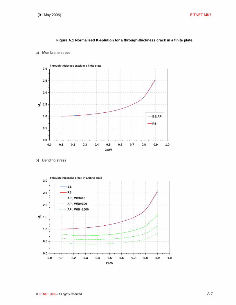
Validity limits For the finite width case ‘any a/W’ API 579 solution [A.15][A.16] The finite width correction factor is as given above for BS 7910 (although the terminology is different). A thickness-dependent term is given for Mb. Plots The functions recommended by various procedures are shown in as a function of relative crack size a/W. Note that the API solutions for Mb are not actually implemented in the API-based software FractureGraphic, which uses Mb=1 instead. BS 7910 and R6 solutions diverge slightly for large a/W because of differences in the definition of fW.
(01 May 2006) FITNET MK7
© FITNET 2006– All rights reserved A-7
Figure A.1 Normalised K-solution for a through-thickness crack in a finite plate
a) Membrane stress
Through-thickness crack in a finite plate
0.0
0.5
1.0
1.5
2.0
2.5
3.0
0.0 0.1 0.2 0.3 0.4 0.5 0.6 0.7 0.8 0.9 1.02a/W
Mm
BS/API
R6
b) Bending stress
Through-thickness crack in a finite plate
0.0
0.5
1.0
1.5
2.0
2.5
3.0
0.0 0.1 0.2 0.3 0.4 0.5 0.6 0.7 0.8 0.9 1.02a/W
Mb
BS
R6
API, W/B=10
API, W/B=100
API, W/B=1000

FITNET FFS – MK7– Annex A
A-8 © FITNET 2006 – All rights reserved
A.2.2 Surface Crack A.2.2.1 Finite crack
BS 7910 Solution [A.15][A.17] The stress intensity factor solution presented in this section is applicable to both normal restraint and pin-jointed boundary conditions (see Annex B). The stress intensity factor is given by equations (A.1 to (A.6 where M = 1 and:
( ) ( ){ }0.50.5sec / /wf c W a B⎡ ⎤= Π⎣ ⎦ (A.12)
where fW=1.0 if a/2c=0. Mm and Mb are defined below. For Membrane loading Conditions The following conditions apply. 0 / 2 1.00
a c≤ ≤≤ Θ ≤ Π
where θ is the parametric angle around the crack front and
a/B < 1.25 (a/c + 0.6) for 0 ≤ a/2c ≤ 0.1 a/B < 1.0 for 0.1 ≤ a/2c ≤ 1.0
Solution

(01 May 2006) FITNET MK7
© FITNET 2006– All rights reserved A-9
( ) ( ){ }2 41 2 3/ / /mM M M a B M a B gfΘ= + + Φ (A.13)
where M1 = 1.13 − 0.09(a/c) for 0 ≤ a/2c ≤ 0.5 M1 = (c/a)0.5{1 + 0.04(c/a)} for 0.5 < a/2c ≤ 1.0 M2 = [0.89/{0.2 + (a/c)}] − 0.54 for 0 ≤ a/2c ≤ 0.5 M2 = 0.2(c/a)4 for 0.5 < a/2c ≤ 1.0 M3 = 0.5 − 1/{0.65 + (a/c)} + 14{1 − (a/c)}24 for a/2c ≤ 0.5 M3 = −0.11 (c/a)4 for 0.5 < a/2c ≤ 1.0 g = 1 + {0.1 + 0.35(a/B)2}(1 − sinΘ )2 for a/2c ≤ 0.5 g = 1 + {0.1 + 0.35(c/a)(a/B)2}(1 − sinΘ )2 for 0.5 < a/2c ≤ 1.0 fθ = {(a/c)2 cos2Θ + sin2Θ }0.25 for 0 ≤ a/2c ≤ 0.5 fθ = {(c/a)2 sin2Θ + cos2Θ }0.25 for 0.5 < a/2c ≤ 1.0
Φ , the complete elliptic integral of the second kind, may be determined from standard tables or from the following solution, which is sufficiently accurate:
1.65
1 1.464 ac
⎛ ⎞Φ= + ⎜ ⎟⎝ ⎠
(A.14)
for 0 ≤ a/2c ≤ 0.5, and
1.65
1 1.464 ca
⎛ ⎞Φ= + ⎜ ⎟⎝ ⎠
(A.15)
for 0.5 ≤ a/2c ≤ 1.0 Simplifications The following simplifications may be used as indicated. a) At the deepest point on the crack front: g = 1 fθ = 1 for 0 ≤ a/2c ≤ 0.5 fθ = (c/a)0.5 for 0.5 < a/2c ≥ 1
b) At the ends of the crack, θ=0, so that: g = 1.1 + 0.35 (a/B)2 For 0 ≤ a/2c ≤ 0.5 g = 1.1 + 0.35 (c/a) (a/B)2 For 0.5 < a/2c ≤ 1.0 fθ = (a/c)0.5 For 0 ≤ a/2c ≤ 0.5

FITNET FFS – MK7– Annex A
A-10 © FITNET 2006 – All rights reserved
fθ = 1.0 For 0.5 < a/2c ≤ 1.0 c) If a/2c > 1.0 use solution for a/2c = 1.0. For Bending loading Conditions The conditions are as given for membrane loading Solutions
b mM HM= (A.16)
where Mm is calculated from equation (A.13
( )1 2 1 sinqH H H H= + − Θ (A.17)
where
q = 0.2 + (a/c) + 0.6(a/B) for 0 ≤ a/2c ≤ 0.5 q = 0.2 + (c/a) + 0.6(a/B) for 0.5 < a/2c ≤ 1.0 H1 = 1 − 0.34(a/B) − 0.11(a/c)(a/B) for 0 ≤ a/2c ≤ 0.5 H1 = 1 – {0.04 + 0.41(c/a)}(a/B) + {0.55 − 1.93(c/a)0.75 +
1.38(c/a)1.5}(a/B)2 for 0.5 < a/2c ≤ 1.0
H2 = 1 + G1 (a/B) + G2 (a/B)2 where
G1 = −1.22 − 0.12(a/c) for 0 ≤ a/2c ≤ 0.5 G1 = − 2.11 + 0.77(c/a) for 0.5 < a/2c ≤ 1.0 G2 = 0.55 − 1.05(a/c)0.75 + 0.47(a/c)1.5 for 0 ≤ a/2c ≤ 0.5 G2 = 0.55 − 0.72(c/a)0.75 + 0.14 (c/a)1.5 for 0.5 < a/2c ≤ 1.0
Simplifications The following simplifications may be used as indicated. a) At the deepest point on the crack front, θ=π/2, so that H = H2 and:
g = 1
fθ = 1 for 0 ≤ a/2c ≤ 0.5 fθ = (c/a)0.5 for 0.5 < a/2c ≤ 1
b) At the ends of the crack, Θ = 0, so that:
g = 1.1 + 0.35(a/B)2 for 0 ≤ a/2c ≤ 0.5; g = 1.1 + 0.35(c/a)(a/B)2 for 0.5 < a/2c ≤ 1.0; fθ = (a/c)0.5 for 0 ≤ a/2c ≤ 0.5; fθ = 1.0 for 0.5 < a/2c ≤ 1.0;

(01 May 2006) FITNET MK7
© FITNET 2006– All rights reserved A-11
and H = H1. c) If a/2c > 1.0, use solution for a/2c = 1.0. For a finite plate, the values should be multiplied by the finite width correction factor, fW, in accordance with equations (A.1 to A.6. Validity limits The finite width correction factor is valid for 2c/W<0.8 0<=a/2c<=1.0 R6 Solution [A.14][A.18] The stress intensity factor KI is given by
5
0, / 2I i i
i
aK a P f a cB
π=
⎛ ⎞= ⎜ ⎟⎝ ⎠
∑ (A.18)
Pi (i = 0 to 5) are stress components which define the stress distribution P according to
( )5
0 for 0
i
ii
uP P u P u aa=
⎛ ⎞= = ≤ ≤⎜ ⎟⎝ ⎠
∑ (A.19)
where P is to be taken normal to the prospective crack plane in an uncracked plate. The co-ordinate u is the distance from the plate surface as shown above. fi (i = 0 to 5) are geometry functions which are given in Table A.1 and Table A.2 below for the deepest point of the crack (position A, θ=90º), and at the intersection of the crack with the free surface (position B, θ=0º), respectively.

FITNET FFS – MK7– Annex A
A-12 © FITNET 2006 – All rights reserved
Table A.1 R6 geometry functions for a finite surface crack in an infinite plate: deepest point of the crack (position A, θ=90º)
a/2c=0.5 a/B f0
A f1A f2
A f3A f4
A f5A
0 0.659 0.471 0.387 0.337 0.299 0.266
0.2 0.663 0.473 0.388 0.337 0.299 0.269
0.4 0.678 0.479 0.390 0.339 0.300 0.271
0.6 0.692 0.486 0.396 0.342 0.304 0.274
0.8 0.697 0.497 0.405 0.349 0.309 0.278
a/2c=0.4 a/B f0
A f1A f2
A f3A f4
A f5A
0 0.741 0.510 0.411 0.346 0.300 0.266
0.2 0.746 0.512 0.413 0.352 0.306 0.270
0.4 0.771 0.519 0.416 0.356 0.309 0.278
0.6 0.800 0.531 0.422 0.362 0.317 0.284
0.8 0.820 0.548 0.436 0.375 0.326 0.295
a/2c=0.3 a/B f0
A f1A f2
A f3A f4
A f5A
0 0.833 0.549 0.425 0.351 0.301 0.267
0.2 0.841 0.554 0.430 0.359 0.309 0.271
0.4 0.885 0.568 0.442 0.371 0.320 0.285
0.6 0.930 0.587 0.454 0.381 0.331 0.295
0.8 0.960 0.605 0.476 0.399 0.346 0.310
a/2c=0.2 a/B f0
A f1A f2
A f3A f4
A f5A
0 0.939 0.580 0.434 0.353 0.302 0.268
0.2 0.957 0.595 0.446 0.363 0.310 0.273
0.4 1.057 0.631 0.475 0.389 0.332 0.292
0.6 1.146 0.668 0.495 0.407 0.350 0.309
0.8 1.190 0.698 0.521 0.428 0.367 0.324
a/2c=0.1 a/B f0
A f1A f2
A f3A f4
A f5A
0 1.053 0.606 0.443 0.357 0.302 0.269
0.2 1.106 0.640 0.467 0.374 0.314 0.277
0.4 1.306 0.724 0.525 0.420 0.348 0.304
0.6 1.572 0.815 0.571 0.448 0.377 0.327
0.8 1.701 0.880 0.614 0.481 0.399 0.343
a/2c=0.05 a/B f0
A f1A f2
A f3A f4
A f5A
0 1.103 0.680 0.484 0.398 0.344 0.306
0.2 1.199 0.693 0.525 0.426 0.364 0.323

(01 May 2006) FITNET MK7
© FITNET 2006– All rights reserved A-13
0.4 1.492 0.806 0.630 0.499 0.417 0.364
0.6 1.999 1.004 0.838 0.631 0.514 0.437
0.8 2.746 1.276 1.549 1.073 0.817 0.660
a/2c=0.025 a/B f0
A f1A f2
A f3A f4
A f5A
0 1.120 0.686 0.504 0.419 0.365 0.325
0.2 1.245 0.708 0.553 0.452 0.389 0.346
0.4 1.681 0.881 0.682 0.538 0.451 0.394
0.6 2.609 1.251 0.971 0.722 0.583 0.493
0.8 4.330 1.885 2.016 1.369 1.026 0.819
a/2c→ 0 a/B f0
A f1A f2
A f3A f4
A f5A
0 1.123 0.682 0.524 0.440 0.386 0.344
0.2 1.380 0.784 0.582 0.478 0.414 0.369
0.4 2.106 1.059 0.735 0.578 0.485 0.423
0.6 4.025 1.750 1.105 0.814 0.651 0.548
0.8 11.92 4.437 2.484 1.655 1.235 0.977

FITNET FFS – MK7– Annex A
A-14 © FITNET 2006 – All rights reserved
Table A.2 R6 geometry functions for a finite surface crack in an infinite plate: intersection of crack with free surface (position B, θ=0º)
a/2c=0.5 a/B 0 0.716 0.118 0.041 0.022 0.014 0.010
0.2 0.729 0.123 0.045 0.023 0.014 0.010
0.4 0.777 0.133 0.050 0.026 0.015 0.011
0.6 0.839 0.148 0.058 0.029 0.018 0.012
0.8 0.917 0.167 0.066 0.035 0.022 0.015
a/2c=0.4 a/B 0 0.730 0.124 0.041 0.021 0.013 0.010
0.2 0.749 0.126 0.046 0.023 0.014 0.010
0.4 0.795 0.144 0.054 0.028 0.017 0.012
0.6 0.901 0.167 0.066 0.033 0.021 0.015
0.8 0.995 0.193 0.076 0.042 0.026 0.017
a/2c=0.3 a/B 0 0.723 0.118 0.039 0.019 0.011 0.008
0.2 0.747 0.125 0.044 0.022 0.014 0.010
0.4 0.803 0.145 0.056 0.029 0.018 0.012
0.6 0.934 0.180 0.072 0.037 0.023 0.016
0.8 1.070 0.218 0.087 0.047 0.029 0.020
a/2c=0.2 a/B 0 0.673 0.104 0.032 0.015 0.009 0.006
0.2 0.704 0.114 0.038 0.018 0.011 0.007
0.4 0.792 0.139 0.053 0.027 0.016 0.011
0.6 0.921 0.183 0.074 0.038 0.024 0.017
0.8 1.147 0.244 0.097 0.052 0.032 0.021
a/2c=0.1 a/B 0 0.516 0.069 0.017 0.009 0.005 0.004
0.2 0.554 0.076 0.022 0.011 0.007 0.005
0.4 0.655 0.099 0.039 0.019 0.012 0.008
0.6 0.840 0.157 0.063 0.032 0.020 0.013
0.8 1.143 0.243 0.099 0.055 0.034 0.023
a/2c=0.05 a/B
(01 May 2006) FITNET MK7
© FITNET 2006– All rights reserved A-15
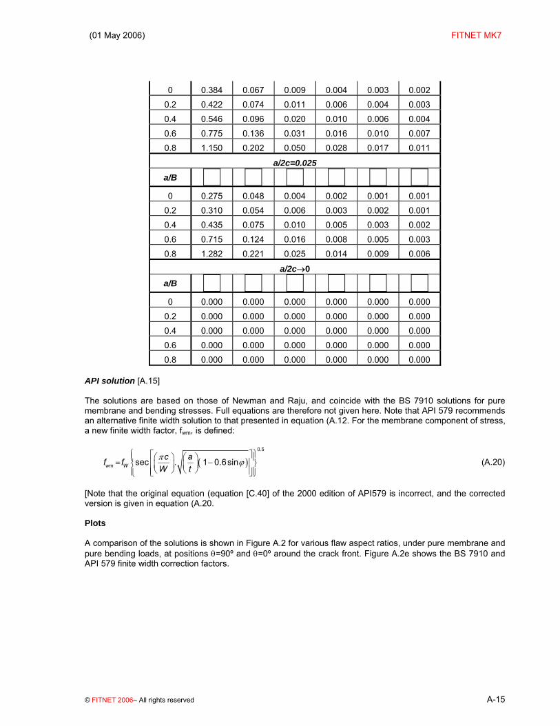
0 0.384 0.067 0.009 0.004 0.003 0.002
0.2 0.422 0.074 0.011 0.006 0.004 0.003
0.4 0.546 0.096 0.020 0.010 0.006 0.004
0.6 0.775 0.136 0.031 0.016 0.010 0.007
0.8 1.150 0.202 0.050 0.028 0.017 0.011
a/2c=0.025 a/B 0 0.275 0.048 0.004 0.002 0.001 0.001
0.2 0.310 0.054 0.006 0.003 0.002 0.001
0.4 0.435 0.075 0.010 0.005 0.003 0.002
0.6 0.715 0.124 0.016 0.008 0.005 0.003
0.8 1.282 0.221 0.025 0.014 0.009 0.006
a/2c→0 a/B 0 0.000 0.000 0.000 0.000 0.000 0.000
0.2 0.000 0.000 0.000 0.000 0.000 0.000
0.4 0.000 0.000 0.000 0.000 0.000 0.000
0.6 0.000 0.000 0.000 0.000 0.000 0.000
0.8 0.000 0.000 0.000 0.000 0.000 0.000 API solution [A.15] The solutions are based on those of Newman and Raju, and coincide with the BS 7910 solutions for pure membrane and bending stresses. Full equations are therefore not given here. Note that API 579 recommends an alternative finite width solution to that presented in equation (A.12. For the membrane component of stress, a new finite width factor, fwm, is defined:
( )0.5
sec . 1 0.6sinwm Wc af f
W tπ ϕ
⎧ ⎫⎡ ⎤⎪ ⎪⎛ ⎞ ⎛ ⎞= −⎢ ⎥⎨ ⎬⎜ ⎟ ⎜ ⎟⎝ ⎠ ⎝ ⎠⎢ ⎥⎪ ⎪⎣ ⎦⎩ ⎭
(A.20)
[Note that the original equation (equation [C.40] of the 2000 edition of API579 is incorrect, and the corrected version is given in equation (A.20. Plots A comparison of the solutions is shown in Figure A.2 for various flaw aspect ratios, under pure membrane and pure bending loads, at positions θ=90º and θ=0º around the crack front. Figure A.2e shows the BS 7910 and API 579 finite width correction factors.

FITNET FFS – MK7– Annex A
A-16 © FITNET 2006 – All rights reserved
Figure A.2 Normalised K-solution for a surface-breaking crack in an infinite plate
Surface crack in an infinite plate; θ=90o
0.0
0.5
1.0
1.5
2.0
2.5
3.0
3.5
0.0 0.2 0.4 0.6 0.8 1.0a/B
Mm
BS, a/2c=0.001BS, a/2c=0.05BS, a/2c=0.1BS, a/2c=0.3BS, a/2c=0.5R6, a/2c=0.05R6, a/2c=0.1R6, a/2c=0.3R6, a/2c=0.5API, a/2c=0.001API, a/2c=0.05API, a/2c=0.1API, a/2c=0.3API, a/2c=0.5
a) Membrane stress, θ=90º
Surface crack in an infinite plate; θ=0o
0.0
0.2
0.4
0.6
0.8
1.0
1.2
1.4
1.6
1.8
2.0
0.0 0.1 0.2 0.3 0.4 0.5 0.6 0.7 0.8 0.9 1.0a/B
Mm
BS, a/2c=0.05BS, a/2c=0.1BS, a/2c=0.3BS, a/2c=0.5R6, a/2c=0.05R6, a/2c=0.1R6, a/2c=0.3R6, a/2c=0.5API, a/2c=0.05API, a/2c=0.1API, a/2c=0.3API, a/2c=0.5
b) Membrane stress, θ=0º

(01 May 2006) FITNET MK7
© FITNET 2006– All rights reserved A-17
Normalised K-solution for a surface-breaking crack in an infinite plate (cont’d)
Surface crack in an infinite plate; θ=90o
0.0
0.2
0.4
0.6
0.8
1.0
1.2
1.4
1.6
1.8
2.0
0.0 0.1 0.2 0.3 0.4 0.5 0.6 0.7 0.8 0.9 1.0a/B
Mb
BS, a/2c=0.001BS, a/2c=0.05BS, a/2c=0.1BS, a/2c=0.3BS, a/2c=0.5API, a/2c=0.001API, a/2c=0.05API, a/2c=0.1API, a/2c=0.3API, a/2c=0.5R6, a/2c=0.05R6, a/2c=0.10R6, a/2c=0.30R6, a/2c=0.50
c) Bending stress, θ=90º
Surface crack in an infinite plate; θ=0o
0.0
0.2
0.4
0.6
0.8
1.0
1.2
1.4
1.6
1.8
0.0 0.1 0.2 0.3 0.4 0.5 0.6 0.7 0.8 0.9 1.0a/B
Mb
BS, a/2c=0.001BS, a/2c=0.05BS, a/2c=0.1BS, a/2c=0.3BS, a/2c=0.5API, a/2c=0.001API, a/2c=0.05API, a/2c=0.1API, a/2c=0.3API, a/2c=0.5R6, a/2c=0.05R6, a/2c=0.10R6, a/2c=0.30R6, a/2c=0.50
d) Bending stress, θ=0º

FITNET FFS – MK7– Annex A
A-18 © FITNET 2006 – All rights reserved
Normalised K-solution for a surface-breaking crack in an infinite plate (cont’d)
Surface crack in a plate; finite width correction factors
0.98
1.00
1.02
1.04
1.06
1.08
1.10
1.12
1.14
1.16
1.18
0.0 0.1 0.2 0.3 0.4 0.5 0.6 0.7 0.8 0.9 1.0a/B
f W
BS/API, 2c/W=0.5,a/2c=0.1
API, 2c/W=0.5,a/2c=0.1
e) Finite width correction factor

(01 May 2006) FITNET MK7
© FITNET 2006– All rights reserved A-19
A.2.2.2 Extended crack
BS 7910 solution [A.3] The stress intensity factor is given by equations (A.1 to (A.6, where fw = 1, and Mm and Mb are given below:
Mm = 1.12 − 0.23(a/B) + 10.6(a/B)2 − 21.7(a/B)3 + 30.4(a/B)4 (A.21)
Mb = 1.12 − 1.39(a/B) + 7.32(a/B)2 − 13.1(a/B)3 + 14(a/B)4 (A.22)
Validity limits a/B≤ 0.6 R6 Solution [A.19] [Wu and Carlsson] The stress intensity factor KI is given by
( ) ( )3
5 2
10
1 / 12
ia i
I ii
uK P u f a B duaaπ
−=
−
⎛ ⎞= −⎜ ⎟⎝ ⎠
∑∫ (A.23)
The stress state P = P(u) is to be taken normal to the prospective crack plane in an uncracked plate. The co-ordinate u is defined in the figure above. The geometry functions fi (i = 1 to 5) are given in Table A.3.

FITNET FFS – MK7– Annex A
A-20 © FITNET 2006 – All rights reserved
Table A.3 R6 geometry functions for an extended surface crack in an infinite width plate.
a/B f1A f2
A f3A f4
A f5A
0 2.000 0.977 1.142 -0.350 -0.091
0.1 2.000 1.419 1.138 -0.355 -0.076
0.2 2.000 2.537 1.238 -0.347 -0.056
0.3 2.000 4.238 1.680 -0.410 -0.019
0.4 2.000 6.636 2.805 -0.611 0.039
0.5 2.000 10.02 5.500 -1.340 0.218
0.6 2.000 15.04 11.88 -3.607 0.786
0.7 2.000 23.18 28.03 -10.50 2.587
0.8 2.000 38.81 78.75 -36.60 9.871
0.9 2.000 82.70 351.0 -207.1 60.86
Plots Solutions for pure membrane and bending stresses are shown in Figure A.3. Selected solutions from Section A.2.2.1 (low aspect ratio flaws) are shown for comparison.

(01 May 2006) FITNET MK7
© FITNET 2006– All rights reserved A-21
Figure A.3 Normalised K-solution for an extended surface crack in a plate
Extended surface crack in a plate
0.0
0.5
1.0
1.5
2.0
2.5
3.0
3.5
4.0
4.5
0 0.1 0.2 0.3 0.4 0.5 0.6 0.7a/B
Mm
BS, a/2c=0
R6, a/2c=0
API,a/2c=0.001
a) Membrane stress
Extended surface crack in a plate
0.0
0.5
1.0
1.5
2.0
2.5
3.0
0 0.1 0.2 0.3 0.4 0.5 0.6 0.7 0.8a/B
Mb
BS, a/2c=0
BS, a/2c=0.001
R6, a/2c=0
b) Bending stress

FITNET FFS – MK7– Annex A
A-22 © FITNET 2006 – All rights reserved
A.2.2.3 Extended double crack
This case is considered as a double edge crack in an infinite plate (see Section A.2.5.2)
(01 May 2006) FITNET MK7
© FITNET 2006– All rights reserved A-23
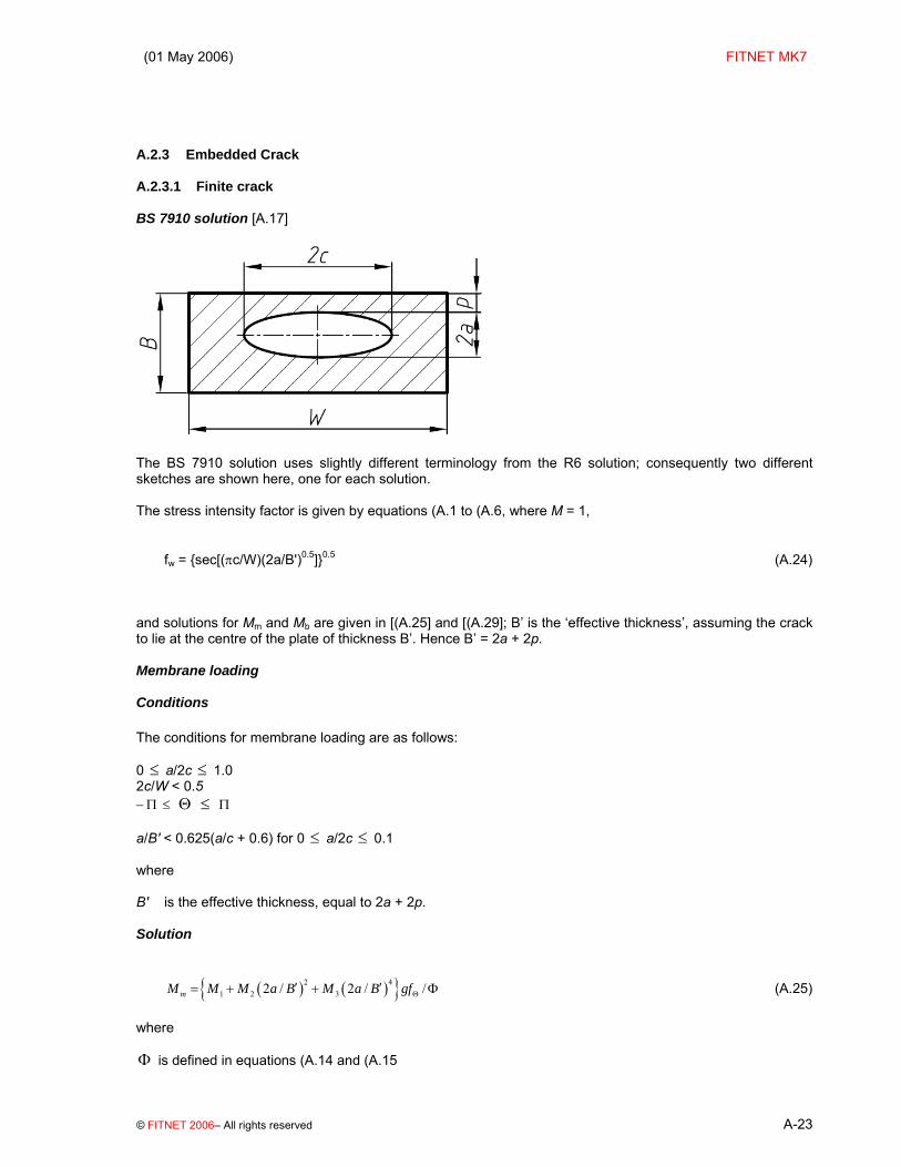
A.2.3 Embedded Crack A.2.3.1 Finite crack BS 7910 solution [A.17]
The BS 7910 solution uses slightly different terminology from the R6 solution; consequently two different sketches are shown here, one for each solution. The stress intensity factor is given by equations (A.1 to (A.6, where M = 1,
fw = {sec[(πc/W)(2a/B')0.5]}0.5 (A.24)
and solutions for Mm and Mb are given in [(A.25] and [(A.29]; B’ is the ‘effective thickness’, assuming the crack to lie at the centre of the plate of thickness B’. Hence B’ = 2a + 2p. Membrane loading Conditions The conditions for membrane loading are as follows: 0 ≤ a/2c ≤ 1.0 2c/W < 0.5 −Π ≤ Θ ≤ Π a/B' < 0.625(a/c + 0.6) for 0 ≤ a/2c ≤ 0.1 where B' is the effective thickness, equal to 2a + 2p. Solution
( ) ( ){ }2 41 2 32 / 2 / /mM M M a B M a B gfΘ′ ′= + + Φ (A.25)
where Φ is defined in equations (A.14 and (A.15
FITNET FFS – MK7– Annex A
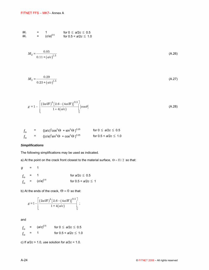
A-24 © FITNET 2006 – All rights reserved
M1 = 1 for 0 ≤ a/2c ≤ 0.5 M1 = (c/a)0.5 for 0.5 < a/2c ≤ 1.0
( )2 1.5
0.050.11 /
M = + a c
(A.26)
( )3 1.5
0.290.23 /
M = + a c
(A.27)
( ) ( ){ }( )
0.542 / 2.6 4 /1 cos
1 4 /a B a B
g = a c
θ⎡ ⎤′ ′−⎢ ⎥−⎢ ⎥+⎢ ⎥⎣ ⎦
(A.28)
fΘ = {(a/c)2cos2Θ + sin2Θ }0.25 for 0 ≤ a/2c ≤ 0.5
fΘ = {(c/a)2sin2Θ + cos2Θ }0.25 for 0.5 < a/2c ≤ 1.0
Simplifications The following simplifications may be used as indicated. a) At the point on the crack front closest to the material surface, / 2Θ = Π so that: g = 1
fΘ = 1 for a/2c ≤ 0.5
fΘ = (c/a)0.5 for 0.5 < a/2c ≤ 1
b) At the ends of the crack, 0Θ = so that:
( ) ( ){ }( )
0.542 / 2.6 4 /1
1 + 4 /a B a B
g = a c
⎡ ⎤′ ′−⎢ ⎥−⎢ ⎥⎢ ⎥⎣ ⎦
;
and fΘ = (a/c)0.5 for 0 ≤ a/2c ≤ 0.5
fΘ = 1 for 0.5 < a/2c ≤ 1.0
c) If a/2c > 1.0, use solution for a/2c = 1.0.

(01 May 2006) FITNET MK7
© FITNET 2006– All rights reserved A-25
Bending loading Conditions The conditions for bending loading are as follows: 0 ≤ a/2c ≤ 0.5
/ 2Θ = Π (ie solution only refers to the ends of the minor axis of the elliptical crack). Solution
( ) ( ) ( )21 2 3 4/ / / /bM p B a B pa Bλ λ λ λ⎡ ⎤= + + + Φ⎣ ⎦ (A.29)
where ― for p/B ≤ 0.184 1:
1λ = 1.044
2λ = –2.44
3λ = 0
4λ = –3.166 ― for p/B > 0.184 1 and a/B ≤ 0.125:
1λ = 0.94
2λ = –1.875
3λ = –0.114 6
4λ = –1.844 ― for p/B > 0.184 1 and a/B > 0.125:
1λ = 1.06
2λ = –2.20
3λ = 4λ = –0.666 6 Validity limits Finite width equation is ‘safe’ up to 2c/W=0.8 For membrane loading: 0 ≤ a/2c ≤ 1.0 2c/W < 0.5

FITNET FFS – MK7– Annex A
A-26 © FITNET 2006 – All rights reserved
-π ≤ θ ≤ π a/B’ < 0.625(a/c+0.6) for 0 ≤ a/2c ≤ 0.1, where B’ = 2a + 2p For bending loading: 0 ≤ a/2c ≤ 0.5 θ = π/2 R6 Solution [A.20]
The stress intensity factor KI is given by
2 2, , , ,I m m b ba a e a a eK a P f P f
B c B B c Bπ
⎛ ⎞⎛ ⎞ ⎛ ⎞= +⎜ ⎟⎜ ⎟ ⎜ ⎟⎝ ⎠ ⎝ ⎠⎝ ⎠
(A.30)
Here, the K-solution is given in terms of relative flaw depth (2a/B), flaw aspect ratio (a/c) and the displacement of the flaw from the centre of the plate (e/B), where e/B=0 denotes a centrally located flaw. In equation (A.30, Pm and Pb are the membrane and bending stress components respectively, which define the stress state P according to
2( ) 1m buP P u P P
B⎛ ⎞= = + −⎜ ⎟⎝ ⎠
(A.31)
for 0 ≤ u ≤ B
The stress P is to be taken normal to the prospective crack plane in an uncracked plate. Pm and Pb are determined by fitting P to equation (A.31. The co-ordinate u is defined in the figure above. The geometry functions fm and fb are given in Table A.4 and Table A.5 for Points A (close to the smaller ligament) and B (close to the larger ligament) respectively.

(01 May 2006) FITNET MK7
© FITNET 2006– All rights reserved A-27
Table A.4 R6 geometry functions for an embedded elliptical crack in an infinite width plate at Point A (closest to u = 0)
a/c=1 e/B = 0 e/B = 0.15 e/B = 0.3
2a/B 0 0.638 0.000 0.638 0.191 0.638 0.383
0.2 0.649 0.087 0.659 0.286 0.694 0.509
0.4 0.681 0.182 0.725 0.411 - -
0.6 0.739 0.296 0.870 0.609 - -
a/c=0.5 e/B = 0 e/B = 0.15 e/B = 0.3
2a/B
0 0.824 0.000 0.824 0.247 0.824 0.494
0.2 0.844 0.098 0.862 0.359 0.932 0.668
0.4 0.901 0.210 0.987 0.526 - -
0.6 1.014 0.355 1.332 0.866 - -
a/c=0.25
e/B = 0 e/B = 0.15 e/B = 0.3
2a/B 0 0.917 0.000 0.917 0.275 0.917 0.550
0.2 0.942 0.102 0.966 0.394 1.058 0.749
0.4 1.016 0.220 1.129 0.584 - -
0.6 1.166 0.379 1.655 1.034 - -
a/c→0
e/B = 0 e/B = 0.15 e/B = 0.3
2a/B 0 1.010 0.000 1.010 0.303 1.010 0.606
0.2 1.041 0.104 1.071 0.428 1.189 0.833
0.4 1.133 0.227 1.282 0.641 - -
0.6 1.329 0.399 2.093 1.256 - -

FITNET FFS – MK7– Annex A
A-28 © FITNET 2006 – All rights reserved
Table A.5 R6 geometry functions for an embedded crack in an infinite width plate at Point B (furthest from u = 0)
a/c=1 e/B = 0 e/B = 0.15 e/B = 0.3
2a/B 0 0.638 0.000 0.638 0.191 0.638 0.383
0.2 0.649 -0.087 0.646 0.108 0.648 0.303
0.4 0.681 -0.182 0.668 0.022 - -
0.6 0.739 -0.296 0.705 -0.071 - -
a/c=0.5 e/B = 0 e/B = 0.15 e/B = 0.3
2a/B 0 0.824 0.000 0.824 0.247 0.824 0.494
0.2 0.844 -0.098 0.844 0.155 0.866 0.418
0.4 0.901 -0.210 0.902 0.060 - -
0.6 1.014 -0.355 1.016 -0.051 - -
a/c=0.25 e/B = 0 e/B = 0.15 e/B = 0.3
2a/B 0 0.917 0.000 0.917 0.275 0.917 0.550
0.2 0.942 -0.102 0.945 0.181 0.980 0.482
0.4 1.016 -0.220 1.029 0.086 - -
0.6 1.166 -0.379 1.206 -0.030 - -
a/c→0
e/B = 0 e/B = 0.15 e/B = 0.3
2a/B 0 1.010 0.000 1.010 0.303 1.010 0.606
0.2 1.041 -0.104 1.048 0.210 1.099 0.550
0.4 1.133 -0.227 1.162 0.116 - -
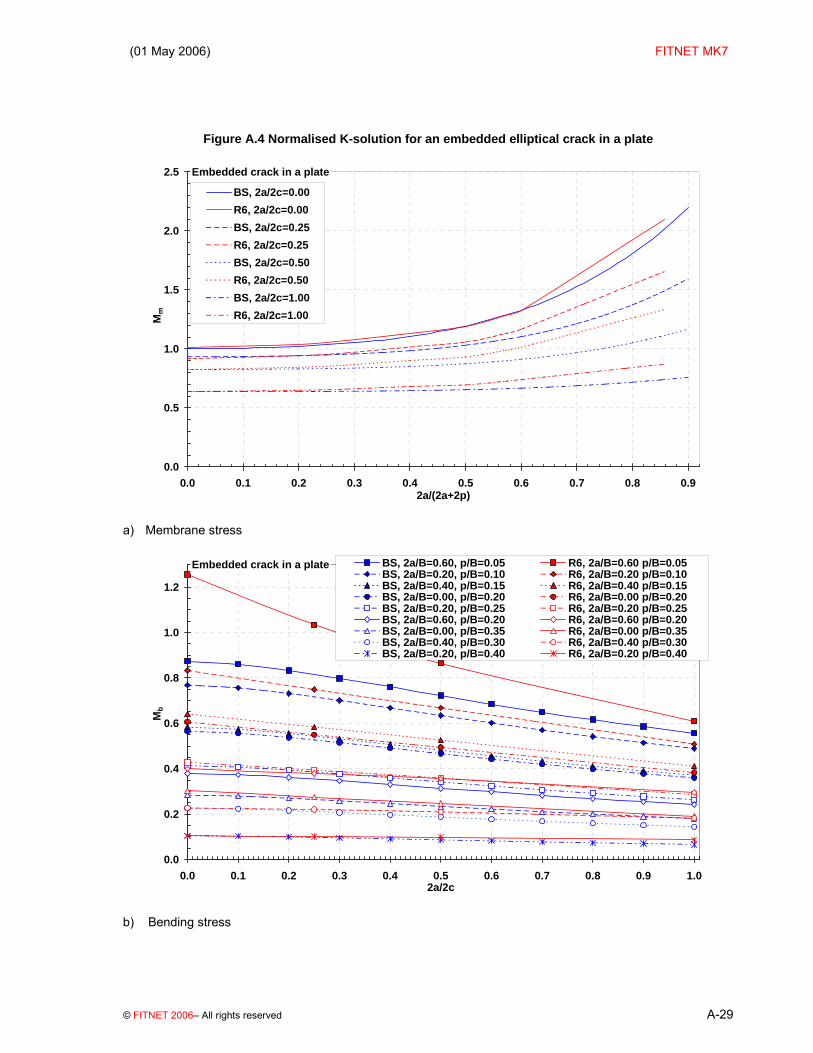
0.6 1.329 -0.399 1.429 0.000 - - Plots Graphical solutions for Mm and Mb at the point nearest the free surface (designated Point ‘A’ in R6) are given in Figure A.4. For membrane loading, the BS 7910 and R6 solutions are close for shallow flaws, diverging somewhat as the through-wall height of the flaw increases, with higher values of Mm from the R6 solution. Under bending, the R6 and BS 7910 solutions are coincident for relatively small, centrally located flaws (low values of 2a/B, high values of p/B), but diverge for larger flaws close to the surface, with the R6 solutions giving higher values of Mb.
(01 May 2006) FITNET MK7
© FITNET 2006– All rights reserved A-29
Figure A.4 Normalised K-solution for an embedded elliptical crack in a plate
Embedded crack in a plate
0.0
0.5
1.0
1.5
2.0
2.5
0.0 0.1 0.2 0.3 0.4 0.5 0.6 0.7 0.8 0.92a/(2a+2p)
Mm
BS, 2a/2c=0.00R6, 2a/2c=0.00BS, 2a/2c=0.25R6, 2a/2c=0.25BS, 2a/2c=0.50R6, 2a/2c=0.50BS, 2a/2c=1.00R6, 2a/2c=1.00
a) Membrane stress
Embedded crack in a plate
0.0
0.2
0.4
0.6
0.8
1.0
1.2
0.0 0.1 0.2 0.3 0.4 0.5 0.6 0.7 0.8 0.9 1.02a/2c
Mb
BS, 2a/B=0.60, p/B=0.05 R6, 2a/B=0.60 p/B=0.05BS, 2a/B=0.20, p/B=0.10 R6, 2a/B=0.20 p/B=0.10BS, 2a/B=0.40, p/B=0.15 R6, 2a/B=0.40 p/B=0.15BS, 2a/B=0.00, p/B=0.20 R6, 2a/B=0.00 p/B=0.20BS, 2a/B=0.20, p/B=0.25 R6, 2a/B=0.20 p/B=0.25BS, 2a/B=0.60, p/B=0.20 R6, 2a/B=0.60 p/B=0.20BS, 2a/B=0.00, p/B=0.35 R6, 2a/B=0.00 p/B=0.35BS, 2a/B=0.40, p/B=0.30 R6, 2a/B=0.40 p/B=0.30BS, 2a/B=0.20, p/B=0.40 R6, 2a/B=0.20 p/B=0.40
b) Bending stress

FITNET FFS – MK7– Annex A
A-30 © FITNET 2006 – All rights reserved
A.2.3.2 Extended crack
BS 7910, R6 No specific solution is given, although the solutions for finite cracks given in Section A.2.3.1 for a/c→0 can be used. API 579 Solution [A.21]
API 579 gives a solution in terms of the distances, d1 and d2, between the free surface and the mid-point of the crack, and a, the half-height of the crack. The API equations have been re-written below in terms of p, the smaller of the two ligament heights, for consistency with Section A.2.3.2 and BS 7910 nomenclature. Hence d1=p+a, and, for a through-wall 4th order polynomial stress distribution:
+⎭⎬⎫
⎩⎨⎧
⎥⎦⎤
⎢⎣⎡ +
+⎥⎦⎤
⎢⎣⎡ +
+⎥⎦⎤
⎢⎣⎡ +
+⎥⎦⎤
⎢⎣⎡ +
+=4
4
3
3
2
2100 Bpa
Bpa
Bpa
BpaMY σσσσσ
(A.32)
+⎥⎦⎤
⎢⎣⎡
⎭⎬⎫
⎩⎨⎧
⎥⎦⎤
⎢⎣⎡ +
+⎥⎦⎤
⎢⎣⎡ +
+⎥⎦⎤
⎢⎣⎡ +
+Ba
Bpa
Bpa
BpaM
3
4
2
3211 432 σσσσ
+⎥⎦⎤
⎢⎣⎡
⎭⎬⎫
⎩⎨⎧
⎥⎦⎤
⎢⎣⎡ +
+⎥⎦⎤
⎢⎣⎡ +
+22
4322 63Ba
Bpa
BpaM σσσ
4
44
3
433 4 ⎥⎦⎤
⎢⎣⎡+⎥⎦
⎤⎢⎣⎡⎭⎬⎫
⎩⎨⎧
⎥⎦⎤
⎢⎣⎡ +
+BaM
Ba
BpaM σσσ
where the coefficients M0 to M4 are given in Table A.6. Solutions are given for the crack front close to the surface (A) and the other crack front (B).

(01 May 2006) FITNET MK7
© FITNET 2006– All rights reserved A-31
Table A.6 API coefficients for an extended embedded crack in a plate Point A Point B
p aB+
( )2 2
aB Bp a⎛ ⎞⎡ ⎤− + −⎜ ⎟⎢ ⎥⎣ ⎦⎝ ⎠
M0 M1 M2 M3 M4 M0 M1 M2 M3 M4 0.20 1.0211 -0.4759 0.4601 -0.3141 0.3025 1.0180 0.4777 0.4600 0.3165 0.3034 0.40 1.0923 -0.4804 0.4779 -0.3162 0.3113 1.0651 0.4757 0.4715 0.3155 0.3090 0.60 1.2628 -0.5219 0.5423 -0.3521 0.3638 1.1505 0.4806 0.5122 0.3372 0.3491 0.25
0.80 1.7105 -0.6027 0.6859 -0.4216 0.4634 1.3097 0.4740 0.5726 0.3551 0.4030 0.20 1.0259 -0.4758 0.4613 -0.3140 0.3031 1.0259 0.4784 0.4619 0.3168 0.3043 0.40 1.1103 -0.4993 0.5121 -0.3550 0.3587 1.1103 0.4987 0.5110 0.3553 0.3585 0.60 1.3028 -0.5299 0.5691 -0.3795 0.3974 1.3028 0.5292 0.5680 0.3790 0.3965 0.50
0.80 1.8103 -0.6451 0.7104 -0.4432 0.4754 1.8013 0.6446 0.7094 0.4425 0.4744 0.20 1.0180 0.4777 0.4600 0.3165 0.3034 1.0211 -0.4759 0.4601 -0.3141 0.3025 0.40 1.0651 0.4757 0.4715 0.3155 0.3090 1.0923 -0.4804 0.4779 -0.3162 0.3113 0.60 1.1505 0.4806 0.5122 0.3372 0.3491 1.2628 -0.5129 0.5423 -0.3521 0.3638 0.75
0.80 1.3097 0.4740 0.5726 0.3551 0.4030 1.7105 -0.6027 0.6859 -0.4216 0.4634 The solution can be used for cylinders and spheres when B/ri ≤ 0.2. In this case, the finite width correction factor should be set to 1. Validity limits: (BS 7910 terminology) p/B ≥ 0.2 when p+a ≤ B/2 (B-(p+2a))/B ≥ 0.2 when B-(p+2a) ≤ B/2 0.25 ≤ (p+a)/B ≤ 0.75 FKM Solution [A.22][A.2] The FKM procedure contains a solution for a centrally located flaw only:
( ) ( )⎥⎦⎤
⎢⎣⎡
+−=
Ba
Ba
Ba
M m
2cos
06.0025.0142
π
(A.33)
Validity limits: None given Plots Figure A.5 compares the API and FKM functions with the R6 and BSI solutions for embedded flaws of low aspect ratio (see Section A.2.3.1). The (p+a)/B variable shows crack position, with (p+a)/B=0.5 indicating a centrally located crack. Note that the API and FKM solutions are more or less coincident for the case of a centrally located crack. Note: The API curves in Figure A.5a are simply the coefficients (here designated M0) from Table C.4 of API 579, whilst the FKM curve is based on a spreadsheet. In Figure A.5b, results for both centrally located and eccentric flaws under bending are shown. The R6 solutions for both Point A (adjacent to the smaller ligament) and B (larger ligament) are indicated, and both points are associated with a positive Mb as expected (the crack is relatively shallow so tensile stress acts throughout the ligament). The API results show Mb to be equal in magnitude and opposite, suggesting that K is evaluated at the same Point (A) but for a bending stress reversed in sign.

FITNET FFS – MK7– Annex A
A-32 © FITNET 2006 – All rights reserved
Figure A.5 Normalised K-solution for an extended embedded crack in a plate
Extended embedded crack in a plate
0.0
0.5
1.0
1.5
2.0
2.5
0.0 0.1 0.2 0.3 0.4 0.5 0.6 0.7 0.8 0.92a/(2a+2p)
Mm
BS, 2a/2c=0.00R6, 2a/2c=0.00API, 2a/2c=0.00, (p+a)/B=0.50API, 2a/2c=0.00, (p+a)/B=0.25API, 2a/2c=0.00, (p+a)/B=0.75FKM, 2a/2c=0.00, (p+a)/B=0.50
a) Membrane stress
Extended embedded crack in a plate
-1.2
-1.0
-0.8
-0.6
-0.4
-0.2
0.0
0.2
0.4
0.6
0.8
1.0
1.2
1.4
0.0 0.1 0.2 0.3 0.4 0.5 0.6 0.7 0.82a/B
Mb BS 7910, 2a/2c=0.00, (a+p)/B=0.50
R6, 2a/2c=0.00, (a+p)/B=0.35, Point AR6, 2a/2c=0.00, centralR6, 2a/2c=0.00, (a+p)/B=0.35, Point BAPI, 2a/2c=0.00, (a+p)/B=0.25API, 2a/2c=0.00, (a+p)/B=0.50API, 2a/2c=0.00, (a+p)/B=0.75
b) Bending stress

(01 May 2006) FITNET MK7
© FITNET 2006– All rights reserved A-33
A.2.4 Edge Crack
A.2.4.1 Single edge crack (tension)
BS 7910 Solution [A.17] The stress intensity factor is given by equations (A.1 to (A.6, where, for a/W ≤ 0.6, M = 1, fw = 1 and:
432
4.307.216.1023.012.1 ⎟⎠⎞
⎜⎝⎛+⎟
⎠⎞
⎜⎝⎛−⎟
⎠⎞
⎜⎝⎛+⎟
⎠⎞
⎜⎝⎛−=
Wa
Wa
Wa
WaM m (A.34)
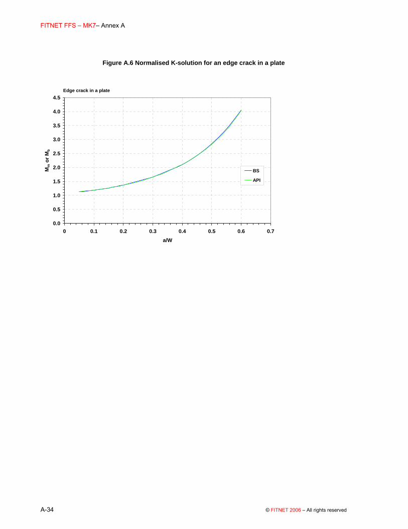
NOTE This solution has the same form as that for long surface cracks (equation (A.21) although the plate membrane and bending stresses have been superimposed. Equation (A.34 does not account for in-plane bending (eg a SENB specimen). In such cases, a modified form of the long surface crack solution may be used. Validity limits Solution does not account for in-plane bending (eg SENB specimen) a/W ≤ 0.6 R6, API 579 No solution available.
FITNET FFS – MK7– Annex A
A-34 © FITNET 2006 – All rights reserved
Figure A.6 Normalised K-solution for an edge crack in a plate
Edge crack in a plate
0.0
0.5
1.0
1.5
2.0
2.5
3.0
3.5
4.0
4.5
0 0.1 0.2 0.3 0.4 0.5 0.6 0.7a/W
Mm
or M
b
BS
API
(01 May 2006) FITNET MK7
© FITNET 2006– All rights reserved A-35
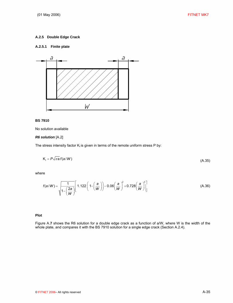
A.2.5 Double Edge Crack
A.2.5.1 Finite plate
BS 7910 No solution available R6 solution [A.2] The stress intensity factor KI is given in terms of the remote uniform stress P by:
IK a ( / )P f a Wπ= (A.35)
where
2 31( / ) 1.122 1 0.06 0.72821
a a af a Wa W W W
W
⎡ ⎤⎛ ⎞⎛ ⎞ ⎛ ⎞ ⎛ ⎞= − − +⎢ ⎥⎜ ⎟⎜ ⎟ ⎜ ⎟ ⎜ ⎟⎛ ⎞ ⎝ ⎠ ⎝ ⎠ ⎝ ⎠⎝ ⎠⎢ ⎥⎣ ⎦− ⎜ ⎟⎝ ⎠
(A.36)
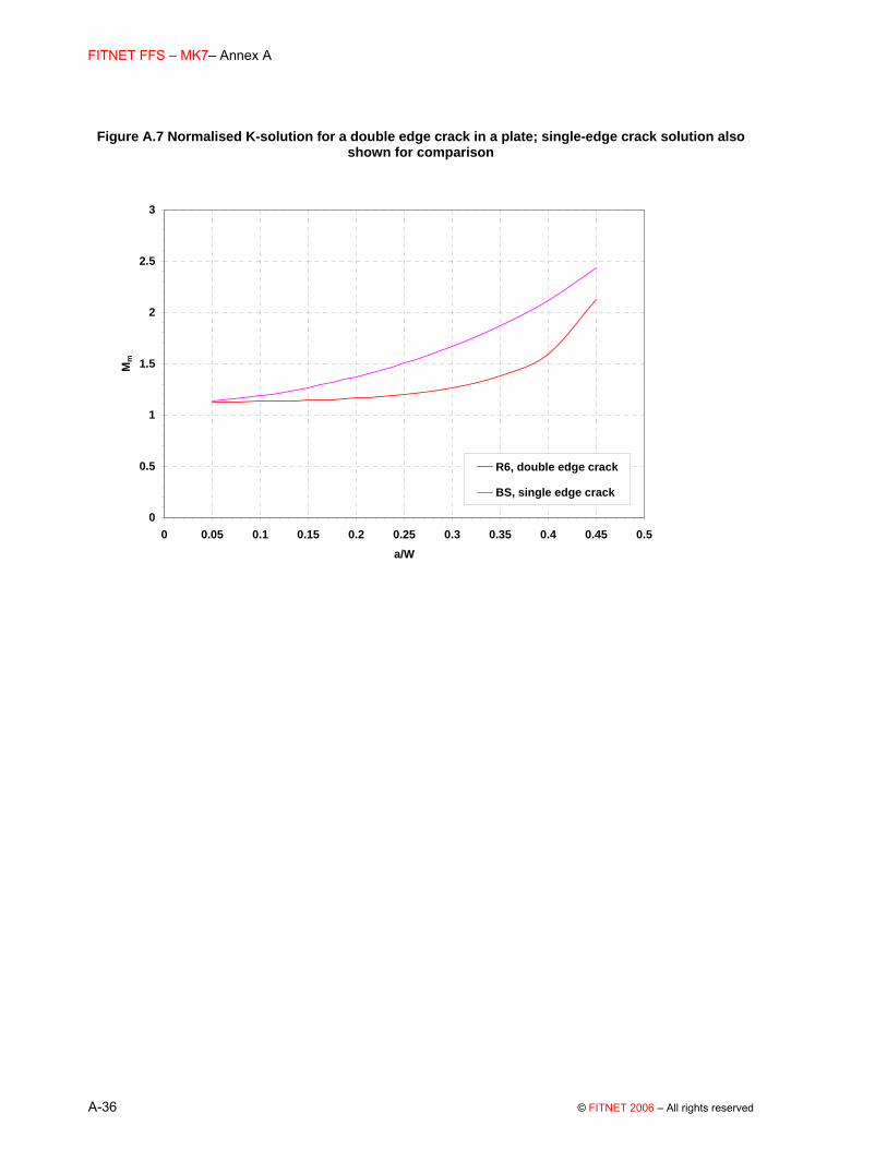
Plot Figure A.7 shows the R6 solution for a double edge crack as a function of a/W, where W is the width of the whole plate, and compares it with the BS 7910 solution for a single edge crack (Section A.2.4).
FITNET FFS – MK7– Annex A
A-36 © FITNET 2006 – All rights reserved
Figure A.7 Normalised K-solution for a double edge crack in a plate; single-edge crack solution also shown for comparison
0
0.5
1
1.5
2
2.5
3
0 0.05 0.1 0.15 0.2 0.25 0.3 0.35 0.4 0.45 0.5a/W
Mm
R6, double edge crack
BS, single edge crack

(01 May 2006) FITNET MK7
© FITNET 2006– All rights reserved A-37
A.2.5.2 Infinite plate BS 7910 No solution available R6 Solution [A.23] For a uniform stress, this is similar to the finite plate solution in Section A.2.5.1; here the plate thickness, 2t, replaces the plate width, W, of the earlier solution.
The stress intensity factor KI for a stress distribution P(x) in the uncracked body which is symmetric about the centre-line of the plate with a value P0 at the mouth of each crack (x=0) is
( )02 /
21I
a FK P f a Ba B
B
π ⎛ ⎞= +⎜ ⎟⎛ ⎞ ⎝ ⎠−⎜ ⎟⎝ ⎠
(A.37)
( )3
/ 1.22 1 0.06 0.728a a af a BB B B
⎛ ⎞ ⎛ ⎞= − − +⎜ ⎟ ⎜ ⎟⎝ ⎠ ⎝ ⎠
(A.38)
and
1
0
/ 2 / 2cos ./ 2 / 2
a B x dP x B aF dxdx a B xπ
− ⎛ ⎞− −⎛ ⎞= ⎜ ⎟⎜ ⎟⎝ ⎠ ⎝ ⎠
∫ (A.39)

FITNET FFS – MK7– Annex A
A-38 © FITNET 2006 – All rights reserved
A.2.6 Corner Crack
BS 7910 Solution [A.17] The stress intensity factor is given by equations (A.1 to (A.6, where M = 1, with fw given in equation (A.40
2 3 41 0.2 9.4 19.4 27.1wf λ λ λ λ= − + − + for / 0.5c W ≤ (A.40)
where:
( ) ( )c W a Bλ = (A.41)
Solutions for Mm and Mb are given below For Membrane loading Conditions 0.2 ≤ a/c ≤ 2, a/B < 1, 0 ≤ Θ ≤ Π /2 and c/W < 0.5. Solution
( ) ( ){ }2 41 2 3 1 2/ / /mM M M a B M a B g g fΘ= + + Φ (A.42)
Where: Φ is defined in equations (A.14 (for 0≤a/c≤1) and (A.15 (for 1≤a/c≤2). M1 = 1.08 − 0.03(a/c) for 0.2 ≤ a/c ≤ 1 M1 = {1.08 − 0.03(c/a)}(c/a)0.5 for 1 < a/c ≤ 2 M2 = {1.06/(0.3 + a/c)} − 0.44 for 0.2 ≤ a/c ≤ 1 M2 = 0.375(c/a)2 for 1 < a/c ≤ 2 M3 = −0.5 + 0.25(a/c) + 14.8(1 − a/c)15 for 0.2 ≤ a/c ≤ 1 M3 = −0.25(c/a)2 for 1 < a/c ≤ 2 g1 = 1 + {0.08 + 0.4(a/B)2} (1 − sinΘ )3 for 0.2 ≤ a/c ≤ 1 g1 = 1 + {0.08 + 0.4(c/B)2} (1 − sinΘ )3 for 1 < a/c ≤ 2 g2 = 1 + {0.08 + 0.15(a/B)2} (1 − cosΘ )3 for 0.2 ≤ a/c ≤ 1 g2 = 1 + {0.08 + 0.15(c/B)2} (1 − cosΘ )3 for 1 ≤ a/c ≤ 2 fΘ = {(a/c)2cos2Θ + sin2Θ }0.25 for 0.2 ≤ a/c ≤ 1
fΘ = {(c/a)2sin2Θ + cos2Θ }0.25 for 1 < a/c ≤ 2

(01 May 2006) FITNET MK7
© FITNET 2006– All rights reserved A-39
For Bending loading Solution
b mM HM= (A.43)
where Mm is given by equation (A.42 and: H = H1 + (H2 – H1) sinq Θ
q = 0.2 + (a/c) + 0.6(a/B) for 0.2 ≤ a/c ≤ 1 q = 0.2 + (c/a) + 0.6(a/B) for 1 < a/c ≤ 2 H1 = 1 − 0.34(a/B) − 0.11(a/c)(a/B) for 0.2 ≤ a/c ≤ 1 H1 = 1 − {0.04 + 0.41(c/a)}(a/B) + {0.55 − 1.93(c/a)0.75 +
1.38(c/a)1.5}(a/B)2 for 1 < a/c ≤ 2
H2 = 1 + G1(a/B) + G2(a/B)2 where G1 = −1.22 − 0.12(a/c) for 0.2 ≤ a/c ≤ 1 G1 = −2.11 + 0.77(c/a) for 1 < a/c ≤ 2 G2 = 0.64 − 1.05(a/c)0.75 + 0.47(a/c)1.5 for 0.2 ≤ a/c ≤ 1 G2 = 0.64 − 0.72(c/a)0.75 + 0.14(c/a)1.5 for 1 < a/c ≤ 2
Validity limits: 0.2 ≤ a/c≤ 2, a/B < 1, 0 ≤ Θ ≤ Π /2 and c/W < 0.5. R6, API579 No solution available.

FITNET FFS – MK7– Annex A
A-40 © FITNET 2006 – All rights reserved
Figure A.8 Normalised K-solution for a corner crack in an infinite plate
Corner flaw in a plate; θ=90o
0.0
0.5
1.0
1.5
2.0
2.5
3.0
0 0.1 0.2 0.3 0.4 0.5 0.6 0.7 0.8 0.9a/B
Mm
BS, a/c=0.2
BS, a/c=1
BS, a/c=2
a) Membrane stress, θ=90º
Corner flaw in a plate; θ=0o
0.0
0.2
0.4
0.6
0.8
1.0
1.2
1.4
0 0.1 0.2 0.3 0.4 0.5 0.6 0.7 0.8 0.9a/B
Mm
BS, a/c=0.2
BS, a/c=1
BS, a/c=2
b) Membrane stress, θ=0º

(01 May 2006) FITNET MK7
© FITNET 2006– All rights reserved A-41
Corner flaw in a plate; θ=90o
-0.2
0.0
0.2
0.4
0.6
0.8
1.0
1.2
0.0 0.1 0.2 0.3 0.4 0.5 0.6 0.7 0.8 0.9
a/B
Mb
BS, a/c=0.2
BS, a/c=1
BS, a/c=2
c) Bending stress, θ=90º
Corner flaw in a plate; θ=0o
0.0
0.1
0.2
0.3
0.4
0.5
0.6
0.7
0.8
0.9
1.0
0.0 0.1 0.2 0.3 0.4 0.5 0.6 0.7 0.8 0.9a/B
Mb
BS, a/c=0.2
BS, a/c=1
BS, a/c=2
d) Bending stress, θ=0º

FITNET FFS – MK7– Annex A
A-42 © FITNET 2006 – All rights reserved
A.2.7 Corner Crack at a Hole (symmetric)
BS 7910 Solution [A.24] Equations (A.1 to (A.6 give the stress intensity factor, where M = 1 and:
( ) ( )( ) ( )
0.52
sec / sec /4 /2 2w
r ncf r W a B
W c ncπ
π⎡ ⎤⎧ ⎫+⎪ ⎪= ⎢ ⎥⎨ ⎬
− +⎪ ⎪⎢ ⎥⎩ ⎭⎣ ⎦ (A.44)
where n = 2 for two symmetric cracks. Equation (A.44 differs from most of the other equations given for fW in this Annex, in that it accounts both for finite width effects and the stress concentrating effect of the hole. Solutions for Mm and Mb are given in equations (A.45 and (A.46. For membrane loading Conditions 0.2 ≤ a/c ≤ 2 a/B < 1 0.5 ≤ r/B ≤ 2 2(r + c)/W ≤ 0.5 0 ≤ Θ ≤ Π /2 Solution
( ) ( ){ }2 41 2 3 1 2 3 4/ / /mM M M a B M a B g g g g fΘ= + + Φ (A.45)
where Φ is defined in equation (A.14 and (A.15 M1 = 1.13 − 0.09(a/c) for 0.2 ≤ a/c ≤ 1 M1 = {1 + 0.04(c/a)} ( )ac / for 1 < a/c ≤ 2
M2 = −0.54 + 0.89/(0.2 + a/c) for 0.2 ≤ a/c ≤ 1 M2 = 0.2(c/a)4 for 1 < a/c ≤ 2 M3 = 0.5 − 1/(0.65 + a/c) + 14(1 − a/c)24 for 0.2 ≤ a/c ≤ 1
(01 May 2006) FITNET MK7
© FITNET 2006– All rights reserved A-43
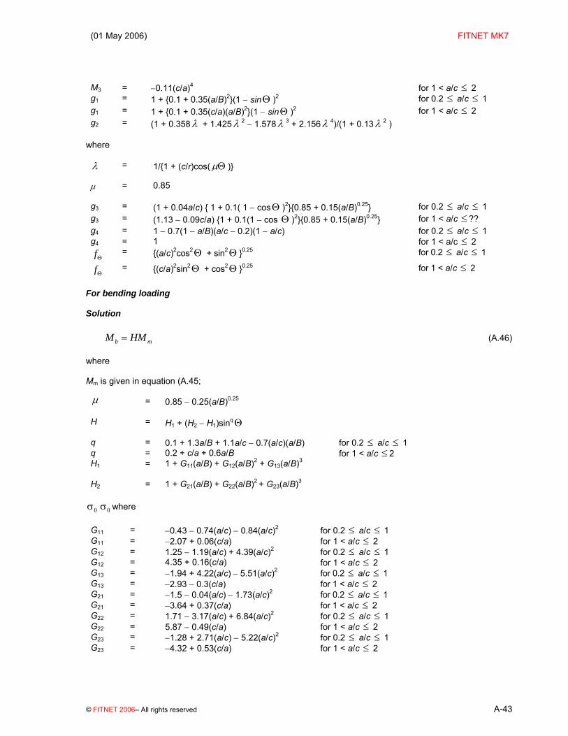
M3 = −0.11(c/a)4 for 1 < a/c ≤ 2 g1 = 1 + {0.1 + 0.35(a/B)2}(1 − sinΘ )2 for 0.2 ≤ a/c ≤ 1 g1 = 1 + {0.1 + 0.35(c/a)(a/B)2}(1 − sinΘ )2 for 1 < a/c ≤ 2 g2 = (1 + 0.358λ + 1.425λ 2 − 1.578λ 3 + 2.156λ 4)/(1 + 0.13λ 2 )
where λ = 1/{1 + (c/r)cos(μΘ )}
μ = 0.85
g3 = (1 + 0.04a/c) { 1 + 0.1( 1 − cosΘ )2}{0.85 + 0.15(a/B)0.25} for 0.2 ≤ a/c ≤ 1 g3 = (1.13 − 0.09c/a) {1 + 0.1(1 − cos Θ )2}{0.85 + 0.15(a/B)0.25} for 1 < a/c ≤ ?? g4 = 1 − 0.7(1 − a/B)(a/c − 0.2)(1 − a/c) for 0.2 ≤ a/c ≤ 1 g4 = 1 for 1 < a/c ≤ 2 fΘ = {(a/c)2cos2Θ + sin2Θ }0.25 for 0.2 ≤ a/c ≤ 1
fΘ = {(c/a)2sin2Θ + cos2Θ }0.25 for 1 < a/c ≤ 2
For bending loading Solution
b mM HM= (A.46)
where Mm is given in equation (A.45; μ = 0.85 − 0.25(a/B)0.25
H = H1 + (H2 − H1)sinqΘ
q = 0.1 + 1.3a/B + 1.1a/c − 0.7(a/c)(a/B) for 0.2 ≤ a/c ≤ 1 q = 0.2 + c/a + 0.6a/B for 1 < a/c ≤ 2 H1 = 1 + G11(a/B) + G12(a/B)2 + G13(a/B)3
H2 = 1 + G21(a/B) + G22(a/B)2 + G23(a/B)3
0σ 0σ where G11 = −0.43 − 0.74(a/c) − 0.84(a/c)2 for 0.2 ≤ a/c ≤ 1 G11 = −2.07 + 0.06(c/a) for 1 < a/c ≤ 2 G12 = 1.25 − 1.19(a/c) + 4.39(a/c)2 for 0.2 ≤ a/c ≤ 1 G12 = 4.35 + 0.16(c/a) for 1 < a/c ≤ 2 G13 = −1.94 + 4.22(a/c) − 5.51(a/c)2 for 0.2 ≤ a/c ≤ 1 G13 = −2.93 − 0.3(c/a) for 1 < a/c ≤ 2 G21 = −1.5 − 0.04(a/c) − 1.73(a/c)2 for 0.2 ≤ a/c ≤ 1 G21 = −3.64 + 0.37(c/a) for 1 < a/c ≤ 2 G22 = 1.71 − 3.17(a/c) + 6.84(a/c)2 for 0.2 ≤ a/c ≤ 1 G22 = 5.87 − 0.49(c/a) for 1 < a/c ≤ 2 G23 = −1.28 + 2.71(a/c) − 5.22(a/c)2 for 0.2 ≤ a/c ≤ 1 G23 = −4.32 + 0.53(c/a) for 1 < a/c ≤ 2
FITNET FFS – MK7– Annex A
A-44 © FITNET 2006 – All rights reserved
Validity limits 0.2 ≤ a/c ≤ 2 a/B < 1 0.5 ≤ r/B ≤ 2 2(r+c)/W ≤ 0.5 0 ≤ θ ≤ π/2 R6 No solution available. Figure A.9 shows the normalised K-solution for a pair of symmetric flaws in an infinite plate, for various ratios of B/r (where r is the radius of the hole) and a/c, the flaw aspect ratio.

(01 May 2006) FITNET MK7
© FITNET 2006– All rights reserved A-45
Figure A.9 Normalised K-solution for a pair of symmetric corner cracks at a hole
Symmetric corner cracks at a hole in a plate, θ=90o
0.0
0.5
1.0
1.5
2.0
2.5
3.0
3.5
4.0
0 0.1 0.2 0.3 0.4 0.5 0.6 0.7 0.8 0.9a/B
Mm
a/c=0.2, B/r=0.5
a/c=0.2, B/r=1
a/c=0.2, B/r=2
a/c=1, B/r=0.5
a/c=1, B/r=1
a/c=1, B/r=2
a/c=2, B/r=0.5
a/c=2, B/r=1
a/c=2, B/r=2
a) Membrane stress, θ=90º
Symmetric corner cracks at a hole in a plate, θ=0o
0.0
0.2
0.4
0.6
0.8
1.0
1.2
1.4
1.6
1.8
2.0
0 0.1 0.2 0.3 0.4 0.5 0.6 0.7 0.8 0.9a/B
Mm
a/c=0.2, B/r=1
a/c=1, B/r=1
a/c=2, B/r=1
b) Membrane stress, θ=0º

FITNET FFS – MK7– Annex A
A-46 © FITNET 2006 – All rights reserved
Normalised K-solution for a pair of symmetric corner cracks at a hole (cont’d)
Symmetric corner cracks at a hole in a plate, θ=90o
0.0
0.5
1.0
1.5
2.0
2.5
3.0
3.5
0 0.1 0.2 0.3 0.4 0.5 0.6 0.7 0.8 0.9a/B
Mb
BS, a/c=0.2
BS, a/c=1
BS, a/c=2
c) Bending stress, θ=90º, B/r=1
Symmetric corner cracks at a hole in a plate, θ=0o
0.0
0.2
0.4
0.6
0.8
1.0
1.2
1.4
1.6
1.8
2.0
0 0.1 0.2 0.3 0.4 0.5 0.6 0.7 0.8 0.9a/B
Mb
BS, a/c=0.2
BS, a/c=1
BS, a/c=2
d) Bending stress, θ=0º, B/r=1

(01 May 2006) FITNET MK7
© FITNET 2006– All rights reserved A-47
A.2.8 Corner Crack at a Hole (single)
BS 7910 Solution [A.24] The stress intensity factor for a single corner crack at a hole (Ksingle crack) may be estimated from Ksymmetric crack (Section A.2.7) using the following expression:
( ) ( )( ) ( )
0.52
sec / sec /4 /2 2w
r ncf r W a B
W c ncπ
π⎡ ⎤⎧ ⎫+⎪ ⎪= ⎢ ⎥⎨ ⎬− +⎪ ⎪⎢ ⎥⎩ ⎭⎣ ⎦
(A.47)
where n=1 for a single flaw. Equation (A.47 differs from most of the other equations given for fW in this Annex, in that it accounts both for finite width effects and the stress concentrating effect of the hole. Ksymmetric crack for an infinite plate with a hole is found simply by modifying the equation for a symmetric crack as follows:
0.5
sin
42
4gle crack symmetric crack
acBrK K
acBr
π
π
⎛ ⎞+⎜ ⎟⎜ ⎟=⎜ ⎟+⎜ ⎟⎝ ⎠
(A.48)
where Ksummetric crack is found from equations (A.1 to (A.6 with Mm and Mb from equations (A.45 and (A.46. Validity limits as for the symmetric crack R6 No solution available.

FITNET FFS – MK7– Annex A
A-48 © FITNET 2006 – All rights reserved
A.3 Spheres A.3.1 Through-thickness Equatorial Crack
BS 7910 Solution [A.25] The stress intensity factor solution is calculated from equations (A.1 to (A.6 where: M = fw = 1; Mm and Mb are given in Table A.7.
Table A.7 BS 7910 solutions for Mm and Mb for a through-thickness crack in a spherical shell
B/ri = 0.05 B/ri = 0.1 2a/B Mm(o) Mb(o) Mm(i) Mb(i) 2a/B Mm(o) Mb(o) Mm(i) Mb(i)
0.0 1.000 1.000 1.000 −1.000 0.0 1.000 1.000 1.000 −1.000 2.0 1.144 1.020 0.941 −0.995 2.0 1.240 1.031 0.919 −0.993 4.0 1.401 1.050 0.897 −0.992 4.0 1.637 1.074 0.894 −0.993 6.0 1.700 1.080 0.895 −0.993 6.0 2.083 1.111 0.944 −0.997 8.0 2.020 1.106 0.932 −0.996 8.0 2.549 1.143 1.059 −1.003 10.0 2.351 1.130 1.003 −1.001 10.0 3.016 1.170 1.231 −1.011 15.0 3.186 1.180 1.309 −1.014 15.0 4.124 1.226 1.915 −1.031 20.0 3.981 1.219 1.799 −1.028 20.0 5.084 1.272 2.968 −1.050 NOTE (o) is for the intersection of the crack with the outside surface, and (i) the inner.
Range of application: 0 ≤2a/B≤ 20 0.05≤B/ri≤0.1 Validity limits 0 ≤ 2a/B ≤ 20 0.05 ≤ B/ri ≤ 0.1 R6 Solution [A.26][A.27] The stress distribution consists of a uniform stress Pm and a through-wall bending stress Pb. The stress intensity factors at Points A (internal surface) and B (external surface) in the sketch above are as follows (the bending stress is assumed positive at the surface of interest):

(01 May 2006) FITNET MK7
© FITNET 2006– All rights reserved A-49
( )3 3A m bK P G P H aπ= + (A.49)
( )4 4B m bK P G P H aπ= + (A.50)
where:
m
apr B
=
where:
( )/ 2m ir r B= +
and:
( )ρ ρ ρ ρ
ρ ρ ρ ρ
= − + + − +
−− + −
2 3 43
2 3 4
1 0.26066 0.88766 0.015826 0.0252662.99573 ln(
(0.26785 0.39378 0.383574 0.095384 )1.38629
m
Gr B (A.51)
( )ρ ρ ρ ρ
ρ ρ ρ ρ
= + + − + +
−− − + −
2 3 44
2 3 4
1 0.41551 0.82404 0.45458 0.0767142.99573 ln(
( 0.05409 0.24698 0.35622 0.099022 )1.38629
m
Gr B (A.52)
( )ρ ρ ρ ρ ρ ρ
ρ ρ ρ ρ ρ
ρ
= − + − + − + +
−+ − + − +
−
2 3 4 5 63
2 3 4 5
6
0.967 2.5204 6.8405 10.214 8.0057 3.1394 0.486114.60517 ln( /
(0.183 0.4921 3.7129 7.1292 6.2412 2.593252.99573
0.414499 )
m
Hr B
(A.53)
65432
4 043402.045873.07261.10555.37674.23932.192.0 ρρρρρρ +−+−+−=H (A.54)
Validity limits 0≤ρ≤2.2, thin shells (B/rm≤0.1. Note that the lower limit of B/rm is not known, so the solution must be used with caution below B/rm=0.01.

FITNET FFS – MK7– Annex A
A-50 © FITNET 2006 – All rights reserved
Plots Figure A.10 shows the BS 7910 and R6 solutions for two ratios of B/ri: 0.05 and 0.1. The two sets of results differ widely, especially under bending stress. Note that the R6 solutions are reasonably consistent with the trends for through-thickness circumferential and axial flaws in cylinders (see Sections A.4.1.1 and A.4.2.1).

(01 May 2006) FITNET MK7
© FITNET 2006– All rights reserved A-51
Figure A.10 Normalised K-solution for a through-thickness crack in a sphere
Through-thickness crack in a sphere
0.5
1.0
1.5
2.0
2.5
3.0
3.5
4.0
4.5
5.0
5.5
0 5 10 15 202am/B
Mm
(out
side
)
BS, B/ri = 0.10R6, B/ri=0.10BS, B/ri = 0.05R6, B/ri=0.05
a) Membrane stress, outside
Through-thickness crack in a sphere
0.5
1.0
1.5
2.0
2.5
3.0
3.5
4.0
4.5
5.0
5.5
0 5 10 15 202am/B
Mm
(ins
ide)
BS, B/ri = 0.05R6, B/ri=0.05BS, B/ri = 0.10R6, B/ri=0.10
b) Membrane stress, inside

FITNET FFS – MK7– Annex A
A-52 © FITNET 2006 – All rights reserved
Normalised K-solution for a through-thickness crack in a sphere (cont’d)
Through-thickness crack in a sphere
0.4
0.5
0.6
0.7
0.8
0.9
1.0
1.1
1.2
1.3
0 5 10 15 202am/B
Mb
(out
side
)
BS, B/ri = 0.10R6, B/ri=0.10BS, B/ri = 0.05R6, B/ri=0.05
c) Bending stress, outside
Through-thickness crack in a sphere
-1.1
-1.0
-0.9
-0.8
-0.7
-0.6
-0.5
-0.4
-0.3
-0.2
0 5 10 15 202am/B
Mb (
insi
de)
BS, B/ri = 0.10R6, B/ri=0.10BS, B/ri = 0.05R6, B/ri=0.05
d) Bending stress, inside

(01 May 2006) FITNET MK7
© FITNET 2006– All rights reserved A-53
A.3.2 Surface Crack
BS 7910 Solution Flat plate solutions for Mm ((A.13) and Mb ((A.16) are recommended, with.
( ){ }( )
1 /1 /
Ta BMM
a B−
=−
(A.55)
where:
( ){ }0.521 3.2 / 2T mM c r B= + (A.56)
Validity limits: 0 ≤ a/2c ≤ 1.0 0 ≤ θ ≤ π a/B < 1.0 for 0.1 ≤ a/2c ≤ 1.0 R6 solution For internal and external part-circumferential equatorial surface flaws, R6 refers to API 579 solutions. However, it does not recommend their use in assessments. Plots Figure A.11 shows the solution as a function of crack depth for various B/ri ratios and for a constant crack shape, a/2c=0.1. A tighter radius (higher B/ri) is associated with a higher value of Mm; for lower B/ri ratios, the solution matches that for a surface flaw in a plate.

FITNET FFS – MK7– Annex A
A-54 © FITNET 2006 – All rights reserved
Figure A.11 Normalised K-solution for a surface crack in a sphere
Surface crack in a sphere
0
0.5
1
1.5
2
0 0.1 0.2 0.3 0.4 0.5 0.6a/B
Mm
B/ri=0.10, a/2c=0.1
B/ri=0.067, a/2c=0.1
B/ri=0.05, a/2c=0.1
B/ri=0.001, a/2c=0.1
a) Membrane stress, θ=90º

(01 May 2006) FITNET MK7
© FITNET 2006– All rights reserved A-55
A.3.3 Embedded Crack
BS 7910 Solution M=1 Flat plate solutions for Mm ((A.13) and Mb ((A.16) are recommended Validity limits: For Mm 0 ≤ a/2c ≤ 1.0 2c/W < 0.5 -π ≤ θ ≤ π a/B’ < 0.625 for 0 ≤ a/2c ≤ 0.1 where B’ = 2a + 2p For Mb 0 ≤ a/2c ≤ 0.5
/ 2Θ = Π (ie solution only refers to the ends of the minor axis of the elliptical crack). R6 No solution available
FITNET FFS – MK7– Annex A
A-56 © FITNET 2006 – All rights reserved
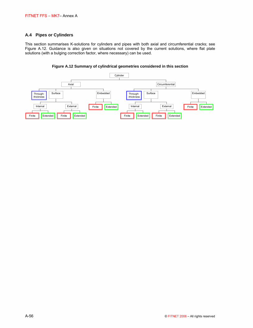
A.4 Pipes or Cylinders This section summarises K-solutions for cylinders and pipes with both axial and circumferential cracks; see Figure A.12. Guidance is also given on situations not covered by the current solutions, where flat plate solutions (with a bulging correction factor, where necessary) can be used.
Figure A.12 Summary of cylindrical geometries considered in this section
Through-thickness
Finite Extended
Internal
Finite Extended
External
Surface
Finite Extended
Embedded
Axial
Through--thickness
Finite Extended
Internal
Finite Extended
External
Surface
Finite Extended
Embedded
Circumferential
Cylinder

(01 May 2006) FITNET MK7
© FITNET 2006– All rights reserved A-57
A.4.1 Pipes or Cylinders with Axial Cracks A.4.1.1 Through-thickness cracks
BS 7910 solution [A.28] The stress intensity factor solution is calculated from equation (A.1 to (A.6 where
KI = KIpressure + KI
bending
M = 1 [Note, bulging is taken into account by the parameter λ: (see equation (A.59) and:
Mm M1 + M2 at the outer surface and M1 – M2 at the inner surface (A.57)
Mb = M3 + M4 at the outer surface and M3 – M4 at the inner surface (A.58)
FITNET FFS – MK7– Annex A
A-58 © FITNET 2006 – All rights reserved
Where: KI
pressure and KIbending are calculated from equation (A.1 to (A.6 and represent, respectively, contributions to KI of
pressure-induced membrane stresses and through-wall bending stresses. M1 to M4 are given in Table A.8a-d for pressure and bending loading, in terms of λ:
( ){ }0.252= 12 1λ ν−m
a r
(A.59)
NOTE The stress intensity magnification factors at the outside (o) and inside (i) surfaces are given by Mm* + Mb*, and Mm* − Mb* respectively. These solutions are valid for long cylinders, or pressure vessels with closed ends.

(01 May 2006) FITNET MK7
© FITNET 2006– All rights reserved A-59
Table A.8 BS 7910 Coefficients for axial through-thickness cracks in cylinders
a) M1 for pressure loading
Parameter, λ B/rm=0.2 B/rm=0.1 B/rm=0.05 B/rm=0.02 B/rm=0.01
0.000 1.000 1.000 1.000 1.000 1.000
0.862 1.158 0.910 1.264
1.016 1.433 1.249 1.285 1.383 1.818 1.609
1.928 1.663 2.012 1.636 2.032 1.912 1.691 3.636 2.543
3.856 2.642 4.024 2.604 4.065 3.133 2.709 5.784 3.613 6.036 3.527 6.097 4.116 3.65* 6.362 3.927
7.712 4.534 7.926 4.980 8.048 4.377 8.130 4.605 8.186 4.799
9.959 5.873 9.998 5.628
10.162 5.463 10.283 5.688 11.816 6.416
11.991 6.687 12.072 5.874 12.194 6.257 12.211 6.503

FITNET FFS – MK7– Annex A
A-60 © FITNET 2006 – All rights reserved
* BS 7910 and the original reference by France et al give a value of 3.369 for λ=6.097, B/rm=0.05. This value lies outside the smooth trend of the other points, and an error is suspected. Substitution of the value M1 =3.65 (obtained by interpolation), produces a smooth curve as shown in Figure A.13.

(01 May 2006) FITNET MK7
© FITNET 2006– All rights reserved A-61
b) M2 for Pressure loading
Parameter, λ B/rm=0.2 B/rm=0.1 B/rm=0.05 B/rm=0.02 B/rm=0.01
0.000 0.000 0.000 0.000 0.000 0.000
0.862 0.093 0.910 0.143
1.016 0.098 0.125 1.285 0.165 1.818 0.229
1.928 0.205 2.012 0.156 2.032 0.143 0.182 3.636 0.218
3.856 0.161 4.024 0.041 4.065 −0.030 0.089 5.784 −0.077 6.036 −0.264 6.097 −0.419 -0.2* 6.362 −0.126
7.712 −0.436 7.926 −0.851 8.048 −0.684 8.130 −0.622 8.186 −0.475
9.959 −1.358 9.998 −0.884
10.162 −1.122 10.283 −1.034 11.816 −1.339
11.991 −1.829 12.072 −1.718 12.194 −1.700 12.211 −1.543

FITNET FFS – MK7– Annex A
A-62 © FITNET 2006 – All rights reserved
* BS 7910 and the original reference by France et al give a value of –0.399 for λ=6.097, B/rm=0.05. This value lies outside the smooth trend of the other points, and an error is suspected. Substitution of the value M2 =-0.2 (obtained by interpolation), produces a smooth curve as shown in Figure A.13.

(01 May 2006) FITNET MK7
© FITNET 2006– All rights reserved A-63
c) M3 for Bending loading
Parameter, λ B/rm=0.2 B/rm=0.1 B/rm=0.05 B/rm=0.02 B/rm=0.01
0.000 0.000 0.000 0.000 0.000 0.000
0.862 0.040 0.910 0.025
1.016 0.053 0.040 1.285 0.042 1.818 0.055
1.928 0.060 2.012 0.075 2.032 0.083 0.068 3.636 0.095
3.856 0.097 4.024 0.109 4.065 0.121 0.103 5.784 0.119 6.036 0.128 6.097 0.139 0.123 6.362 0.127
7.712 0.134 7.926 0.150 8.048 0.138 8.130 0.135 8.186 0.139
9.959 0.161 9.998 0.147
10.162 0.143 10.283 0.145 11.816 0.151
11.991 0.171 12.072 0.150 12.194 0.146 12.211 0.150
FITNET FFS – MK7– Annex A
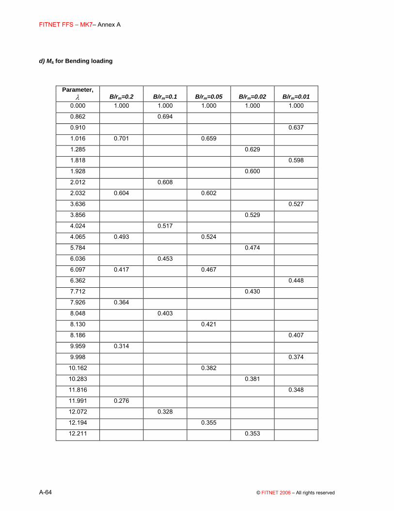
A-64 © FITNET 2006 – All rights reserved
d) M4 for Bending loading
Parameter, λ B/rm=0.2 B/rm=0.1 B/rm=0.05 B/rm=0.02 B/rm=0.01
0.000 1.000 1.000 1.000 1.000 1.000
0.862 0.694 0.910 0.637
1.016 0.701 0.659 1.285 0.629 1.818 0.598
1.928 0.600 2.012 0.608 2.032 0.604 0.602 3.636 0.527
3.856 0.529 4.024 0.517 4.065 0.493 0.524 5.784 0.474 6.036 0.453 6.097 0.417 0.467 6.362 0.448
7.712 0.430 7.926 0.364 8.048 0.403 8.130 0.421 8.186 0.407
9.959 0.314 9.998 0.374
10.162 0.382 10.283 0.381 11.816 0.348
11.991 0.276 12.072 0.328 12.194 0.355 12.211 0.353

(01 May 2006) FITNET MK7
© FITNET 2006– All rights reserved A-65
Validity limits Range of application: 0 12.211λ≤ ≤ 0.01≤B/rm≤0.2 R6 solution [A.26] K is defined for a stress distribution P which varies linearly through the cylinder wall with the co-ordinate u (see sketch above), and which does not vary along the length of the cylinder:
( ) (2 / 1)m bP u P P u B= + − for 0≤u≤B (A.60)
where Pm is the average uniform membrane (hoop) stress and Pb is the maximum through wall bending stress. The stress intensity factors at the Points A (inside wall) and B (outside wall) are given by
( ) ( )1 1 1 1. ( ) ( ) ( ) ( )AI m bK P a G p g p P a H p h pπ π= − + − + (A.61)
( ) ( )( )π ρ ρ π ρ ρ= + + +B
.I m 1 1 1 1K a G g ( ( ) ( ))bP P a H h (A.62)
where:
m/ /a r Bρ = (A.63)
with rm being the mean radius of the cylinder. The functions G1, g1, H1, h1 are given by:
( )( )
12
2 31
m4 2 3
4
G ( ) 1 0.7044 0.8378
g ( ) 0.035211 0.39394 0.20036 0.0280850.01556 0.05202
3.912 ln /B 0.0018763 . 0.0381 0.012782
1.60940.001246
r
ρ ρ ρ
ρ ρ ρ ρ
ρ
ρ ρ ρ
ρ
= + +
= − + − +
− +⎛ ⎞− ⎜ ⎟
− + −⎜ ⎟⎜ ⎟+⎝ ⎠
(A.64)

FITNET FFS – MK7– Annex A
A-66 © FITNET 2006 – All rights reserved
( )( )
2 3 41
m 2 3
4
2 31
H ( ) 0.76871 0.27718 0.14343 0.037505 0.00351940.09852 0.16404
3.912 ln /B + . 0.10378 0.027703
1.60940.002597
h ( ) 0.0030702 0.074457 0.018716 0.0025344
r
ρ ρ ρ ρ ρ
ρρ ρ
ρ
ρ ρ ρ ρ
= − + − +
− +⎛ ⎞− ⎜ ⎟
−⎜ ⎟⎜ ⎟+⎝ ⎠
= − + − +
( )( ) 2m4
3
4
0.0005847 0.0103013.912 ln /B 0.007184
0.00014028 + .1.6094 0.0019107
0.00017655
rρ
ρρ
ρ
ρ
+⎛ ⎞⎜ ⎟− −⎜ ⎟− ⎜ ⎟+⎜ ⎟⎜ ⎟−⎝ ⎠
(A.65)
Plots Figure A.13 shows the BS 7910 and R6 solutions for various B/rm ratios. If the geometry of the cylinder of interest falls outside the range shown, BS 7910 suggests the use of a flat plate solution, with a bulging factor M given by:
2
1 3.22 m
aMr B
= + (A.66)
This flat plate solution is shown for comparison with the BS and R6 solutions. For high values of λ, the solutions for the outer surface diverge, with the flat plate solutions overestimating K relative to the geometry-specific solutions.

(01 May 2006) FITNET MK7
© FITNET 2006– All rights reserved A-67
Figure A.13 Normalised K-solution for an axial through-thickness crack in a cylinder
Axial through-thickness crack in a cylinder
0.0
1.0
2.0
3.0
4.0
5.0
6.0
0.0 2.0 4.0 6.0 8.0 10.0 12.0 14.0λ
Mm
(out
side
)
BS, B/r=0.20 R6, B/r=0.20BS, B/r=0.10 R6, B/r=0.10BS, B/r=0.05 R6, B/r=0.05BS, B/r=0.02 R6, B/r=0.02BS, B/r=0.01 R6, B/r=0.01M: BS 7910, Eq. M.20
λ limit of applicability of R6 solution
a) Outside surface, pressure loading
Axial through-thickness crack in a cylinder
0.0
1.0
2.0
3.0
4.0
5.0
6.0
7.0
8.0
9.0
0.0 2.0 4.0 6.0 8.0 10.0 12.0 14.0λ
Mm
(ins
ide)
BS, B/r=0.20 R6, B/r=0.20BS, B/r=0.10 R6, B/r=0.10BS, B/r=0.05 R6, B/r=0.05BS, B/r=0.02 R6, B/r=0.02BS, B/r=0.01 R6, B/r=0.01M: BS 7910, Eq. M.20
λ limit of applicability of R6 solution
b) Inside surface, pressure loading

FITNET FFS – MK7– Annex A
A-68 © FITNET 2006 – All rights reserved
Normalised K-solution for an axial through-thickness crack in a cylinder (cont’d)
Axial through-thickness crack in a cylinder
0.40
0.45
0.50
0.55
0.60
0.65
0.70
0.75
0.80
0.85
0.90
0.95
1.00
0.0 2.0 4.0 6.0 8.0 10.0 12.0 14.0λ
Mb (
outs
ide)
BS, B/r=0.20 R6, B/r=0.20
BS, B/r=0.10 R6, B/r=0.10
BS, B/r=0.05 R6, B/r=0.05
BS, B/r=0.02 R6, B/r=0.02
BS, B/r=0.01 R6, B/r=0.01
λ limit of applicability of R6 solution
c) Outside surface, bending loading
Axial through-thickness crack in a cylinder
-1.0
-0.9
-0.8
-0.7
-0.6
-0.5
-0.4
-0.3
-0.2
-0.1
0.0
0.0 2.0 4.0 6.0 8.0 10.0 12.0 14.0λ
Mb (
insi
de)
BS, r/B=5 R6, B/r=0.20BS, r/B=10 R6, B/r=0.10BS, r/B=20 R6, B/r=0.05BS, r/B=50 R6, B/r=0.02BS, r/B=100 R6, B/r=0.01
λ limit of applicability of R6 solution
d) Inside surface, bending loading

(01 May 2006) FITNET MK7
© FITNET 2006– All rights reserved A-69
A.4.1.2 Surface cracks
A.4.1.2.1 Internal axial surface crack
a) Finite crack
BS 7910 Solution [A.15][A.29][A.30] The stress intensity factor solution is calculated from equations (A.1 to (A.6 where:
M = fw = 1;
Mm and Mb for the deepest point in the crack (Point A, ie θ=90º) and for the points where the crack intersects the free surface (Point B, ie θ=0º) are given in Table A.9

FITNET FFS – MK7– Annex A
A-70 © FITNET 2006 – All rights reserved
Table A.9 BS 7910 solutions for Mm and Mb for an axial internal surface crack in cylinder
a/2c = 0.5, B/ri = 0.1 a/2c = 0.5, B/ri = 0.25 a/B Mm(A) Mb(A) Mm(B) Mb(B) a/B Mm(A) Mb(A) Mm(B) Mb(B) 0.0 0.663 0.663 0.729 0.729 0.0 0.663 0.663 0.729 0.729 0.2 0.647 0.464 0.726 0.676 0.2 0.643 0.461 0.719 0.669 0.4 0.661 0.291 0.760 0.649 0.4 0.656 0.288 0.745 0.638 0.6 0.677 0.110 0.804 0.623 0.6 0.677 0.107 0.785 0.610 0.8 0.694 -0.080 0.859 0.599 0.8 0.704 -0.079 0.838 0.585
a/2c = 0.2, B/ri = 0.1 a/2c = 0.2, B/ri = 0.25 0.0 0.951 0.951 0.662 0.662 0.0 0.951 0.951 0.662 0.662 0.2 0.932 0.698 0.676 0.632 0.2 0.919 0.688 0.669 0.627 0.4 1.016 0.519 0.768 0.651 0.4 0.998 0.506 0.759 0.644 0.6 1.109 0.316 0.896 0.674 0.6 1.110 0.311 0.889 0.666 0.8 1.211 0.090 1.060 0.700 0.8 1.255 0.103 1.060 0.694
a/2c = 0.1, B/ri = 01 a/2c = 0.1, B/ri = 0.25 0.0 1.059 1.059 0.521 0.521 0.0 1.059 1.059 0.521 0.521 0.2 1.062 0.806 0.578 0.548 0.2 1.045 0.791 0.577 0.547 0.4 1.260 0.677 0.695 0.597 0.4 1.240 0.663 0.698 0.599 0.6 1.500 0.515 0.876 0.660 0.6 1.514 0.515 0.887 0.665 0.8 1.783 0.320 1.123 0.737 0.8 1.865 0.348 1.144 0.745
a/2c = 0.05, B/ri = 0.1 a/2c = 0.05, B/ri = 0.25 0.0 1.103 1.103 0.384 0.384 0.0 1.103 1.103 0.384 0.384 0.2 1.172 0.897 0.451 0.429 0.2 1.153 0.881 0.451 0.428 0.4 1.494 0.834 0.582 0.503 0.4 1.470 0.816 0.585 0.504 0.6 1.985 0.765 0.820 0.623 0.6 2.003 0.765 0.830 0.627 0.8 2.737 0.689 1.219 0.810 0.8 2.864 0.749 1.242 0.819
a/2c = 0.025, B/ri = 0.1 a/2c = 0.025, B/ri = 0.25 0.0 1.120 1.120 0.275 0.275 0.0 1.120 1.120 0.275 0.275 0.2 1.231 0.946 0.335 0.318 0.2 1.211 0.929 0.334 0.318 0.4 1.701 0.971 0.469 0.406 0.4 1.674 0.950 0.471 0.407 0.6 2.619 1.080 0.765 0.584 0.6 2.285 1.079 0.774 0.587 0.8 4.364 1.301 1.374 0.919 0.8 3.163 1.081 1.400 0.928
Validity limits: Range of application: 0 ≤ a/B ≤ 0.8 0.025 ≤ a/2c ≤ 0.5 0.1 ≤ B/ri ≤ 0.25 2c/W ≤ 0.15 R6 solution [A.31] Tabulated geometry functions are given in R6 for restricted values of a/2c and B/ri. These are not repeated here, since for uniform membrane and bending stresses they coincide with the values given by BS 7910, and there are no solutions for arbitrary through-wall stress distributions. Plots Figure A.14 shows the BS 7910 and R6 solutions under membrane and bending stress, at θ=90º (Point A) and θ=0º (Point B), for various B/ri and a/2c ratios. The BS 7910 flat plate solutions (membrane stress only) are shown for comparison, and give a good approximation to the geometry-specific solutions, especially for B/ri=0.1.
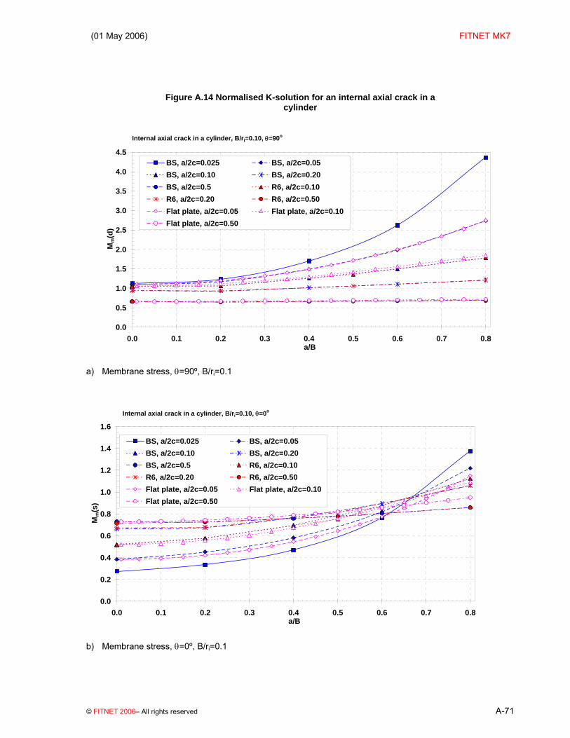
(01 May 2006) FITNET MK7
© FITNET 2006– All rights reserved A-71
Figure A.14 Normalised K-solution for an internal axial crack in a cylinder
Internal axial crack in a cylinder, B/ri=0.10, θ=90o
0.0
0.5
1.0
1.5
2.0
2.5
3.0
3.5
4.0
4.5
0.0 0.1 0.2 0.3 0.4 0.5 0.6 0.7 0.8a/B
Mm
(d)
BS, a/2c=0.025 BS, a/2c=0.05BS, a/2c=0.10 BS, a/2c=0.20BS, a/2c=0.5 R6, a/2c=0.10R6, a/2c=0.20 R6, a/2c=0.50Flat plate, a/2c=0.05 Flat plate, a/2c=0.10Flat plate, a/2c=0.50
a) Membrane stress, θ=90º, B/ri=0.1
Internal axial crack in a cylinder, B/ri=0.10, θ=0o
0.0
0.2
0.4
0.6
0.8
1.0
1.2
1.4
1.6
0.0 0.1 0.2 0.3 0.4 0.5 0.6 0.7 0.8a/B
Mm
(s)
BS, a/2c=0.025 BS, a/2c=0.05BS, a/2c=0.10 BS, a/2c=0.20BS, a/2c=0.5 R6, a/2c=0.10R6, a/2c=0.20 R6, a/2c=0.50Flat plate, a/2c=0.05 Flat plate, a/2c=0.10Flat plate, a/2c=0.50
b) Membrane stress, θ=0º, B/ri=0.1

FITNET FFS – MK7– Annex A
A-72 © FITNET 2006 – All rights reserved
Normalised K-solution for an internal axial crack in a cylinder (cont’d)
Internal axial crack in a cylinder, B/ri=0.10, θ=90o
-0.2
0.0
0.2
0.4
0.6
0.8
1.0
1.2
1.4
1.6
0.0 0.1 0.2 0.3 0.4 0.5 0.6 0.7 0.8a/B
Mb(
d)
BS, a/2c=0.025 BS, a/2c=0.05 BS, a/2c=0.10 BS, a/2c=0.20
BS, a/2c=0.5 R6, a/2c=0.10 R6, a/2c=0.20 R6, a/2c=0.50
c) Bending stress, θ=90º, B/ri=0.1
Internal axial crack in a cylinder, B/ri=0.10, θ=90o
0.2
0.3
0.4
0.5
0.6
0.7
0.8
0.9
1.0
0.0 0.1 0.2 0.3 0.4 0.5 0.6 0.7 0.8a/B
Mb(
d)
BS, a/2c=0.025 BS, a/2c=0.05BS, a/2c=0.10 BS, a/2c=0.20BS, a/2c=0.5 R6, a/2c=0.10R6, a/2c=0.20 R6, a/2c=0.50
d) Bending stress, θ=0º, B/ri=0.1

(01 May 2006) FITNET MK7
© FITNET 2006– All rights reserved A-73
Normalised K-solution for an internal axial crack in a cylinder (cont’d)
Internal axial crack in a cylinder, B/ri=0.25, θ=90o
0.0
0.5
1.0
1.5
2.0
2.5
3.0
3.5
4.0
4.5
0.0 0.1 0.2 0.3 0.4 0.5 0.6 0.7 0.8a/B
Mm
(d)
BS, a/2c=0.025 BS, a/2c=0.05BS, a/2c=0.10 BS, a/2c=0.20BS, a/2c=0.5 R6, a/2c=0.10R6, a/2c=0.20 R6, a/2c=0.50Flat plate, a/2c=0.05 Flat plate, a/2c=0.10Flat plate, a/2c=0.50
e) Membrane stress, θ=90º, B/ri=0.25
Internal axial crack in a cylinder, B/ri=0.25, θ=0o
0.0
0.2
0.4
0.6
0.8
1.0
1.2
1.4
1.6
0.0 0.1 0.2 0.3 0.4 0.5 0.6 0.7 0.8a/B
Mm
(s)
BS, a/2c=0.025 BS, a/2c=0.05BS, a/2c=0.10 BS, a/2c=0.20BS, a/2c=0.5 R6, a/2c=0.10R6, a/2c=0.20 R6, a/2c=0.50Flat plate, a/2c=0.05 Flat plate, a/2c=0.10Flat plate, a/2c=0.50
f) Membrane stress, θ=0º, B/ri=0.25
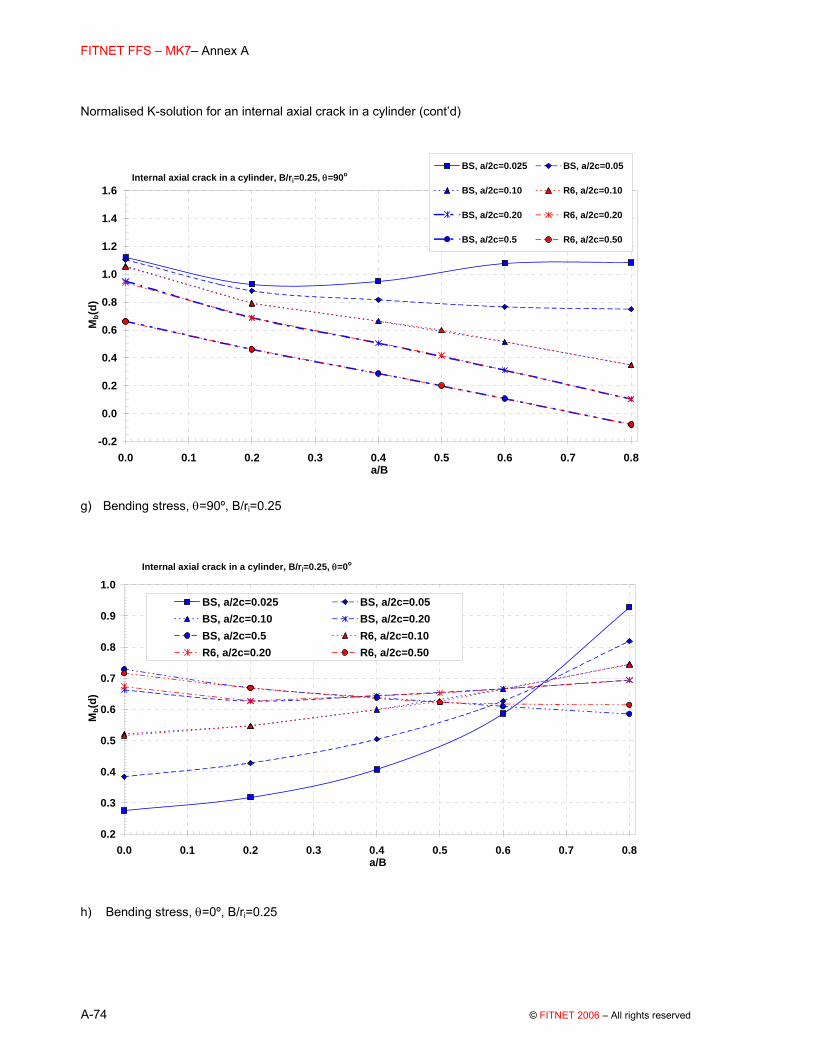
FITNET FFS – MK7– Annex A
A-74 © FITNET 2006 – All rights reserved
Normalised K-solution for an internal axial crack in a cylinder (cont’d)
Internal axial crack in a cylinder, B/ri=0.25, θ=90o
-0.2
0.0
0.2
0.4
0.6
0.8
1.0
1.2
1.4
1.6
0.0 0.1 0.2 0.3 0.4 0.5 0.6 0.7 0.8a/B
Mb(
d)
BS, a/2c=0.025 BS, a/2c=0.05
BS, a/2c=0.10 R6, a/2c=0.10
BS, a/2c=0.20 R6, a/2c=0.20
BS, a/2c=0.5 R6, a/2c=0.50
g) Bending stress, θ=90º, B/ri=0.25
Internal axial crack in a cylinder, B/ri=0.25, θ=0o
0.2
0.3
0.4
0.5
0.6
0.7
0.8
0.9
1.0
0.0 0.1 0.2 0.3 0.4 0.5 0.6 0.7 0.8a/B
Mb(
d)
BS, a/2c=0.025 BS, a/2c=0.05BS, a/2c=0.10 BS, a/2c=0.20BS, a/2c=0.5 R6, a/2c=0.10R6, a/2c=0.20 R6, a/2c=0.50
h) Bending stress, θ=0º, B/ri=0.25

(01 May 2006) FITNET MK7
© FITNET 2006– All rights reserved A-75
b) Extended Crack
BS 7910 Solution [A.29][A.30][A.31] The stress intensity factor solution is calculated from equations (A.1 to (A.6: Where:
M = fw = 1;
Mm and Mb are given in Table A.10 for the deepest point in the crack.
Table A.10 BS 7910 solutions for Mm and Mb for an extended internal axial surface crack in cylinder
B/ri = 0.1 B/ri = 0.25 a/B Mm Mb a/B Mm Mb 0.0 1.122 1.122 0.0 1.122 1.122 0.2 1.380 1.018 0.2 1.304 1.002 0.4 1.930 1.143 0.4 1.784 1.033 0.6 2.960 1.484 0.6 2.566 1.094 0.8 4.820 1.990 0.8 3.461 0.949
Validity limits: 0.0 ≤ a/B ≤ 0.8 0.1 ≤B/ri ≤ 0.25 R6 Solution [A.19] The stress intensity factor KI is given by:
( )π
= −
=
⎛ ⎞= ∫ −⎜ ⎟⎝ ⎠
∑332
0 1
1 ( ) / , / 12
a i i
I i ii
uK P u f a B B r duaa
(A.67)
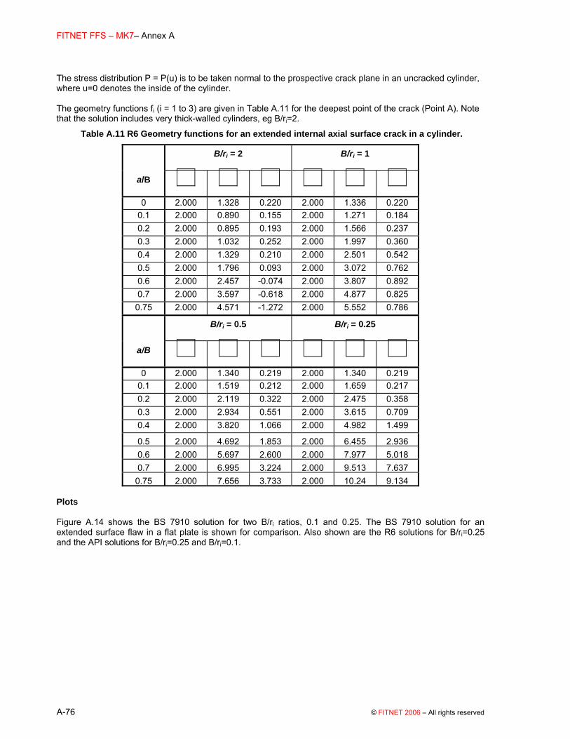
FITNET FFS – MK7– Annex A
A-76 © FITNET 2006 – All rights reserved
The stress distribution P = P(u) is to be taken normal to the prospective crack plane in an uncracked cylinder, where u=0 denotes the inside of the cylinder. The geometry functions fi (i = 1 to 3) are given in Table A.11 for the deepest point of the crack (Point A). Note that the solution includes very thick-walled cylinders, eg B/ri=2.
Table A.11 R6 Geometry functions for an extended internal axial surface crack in a cylinder.
B/ri = 2 B/ri = 1
a/B
0 2.000 1.328 0.220 2.000 1.336 0.220 0.1 2.000 0.890 0.155 2.000 1.271 0.184 0.2 2.000 0.895 0.193 2.000 1.566 0.237 0.3 2.000 1.032 0.252 2.000 1.997 0.360 0.4 2.000 1.329 0.210 2.000 2.501 0.542 0.5 2.000 1.796 0.093 2.000 3.072 0.762 0.6 2.000 2.457 -0.074 2.000 3.807 0.892 0.7 2.000 3.597 -0.618 2.000 4.877 0.825
0.75 2.000 4.571 -1.272 2.000 5.552 0.786
B/ri = 0.5 B/ri = 0.25
a/B
0 2.000 1.340 0.219 2.000 1.340 0.219 0.1 2.000 1.519 0.212 2.000 1.659 0.217 0.2 2.000 2.119 0.322 2.000 2.475 0.358 0.3 2.000 2.934 0.551 2.000 3.615 0.709 0.4 2.000 3.820 1.066 2.000 4.982 1.499
0.5 2.000 4.692 1.853 2.000 6.455 2.936 0.6 2.000 5.697 2.600 2.000 7.977 5.018 0.7 2.000 6.995 3.224 2.000 9.513 7.637
0.75 2.000 7.656 3.733 2.000 10.24 9.134 Plots Figure A.14 shows the BS 7910 solution for two B/ri ratios, 0.1 and 0.25. The BS 7910 solution for an extended surface flaw in a flat plate is shown for comparison. Also shown are the R6 solutions for B/ri=0.25 and the API solutions for B/ri=0.25 and B/ri=0.1.

(01 May 2006) FITNET MK7
© FITNET 2006– All rights reserved A-77
Figure A.15 Normalised K-solution for an extended internal axial crack in a cylinder
Extended internal axial surface flaw in a cylinder
1.0
2.0
3.0
4.0
5.0
6.0
0.0 0.1 0.2 0.3 0.4 0.5 0.6 0.7 0.8a/B
Mm
Flat plateAPI, B/ri=0.10BS, B/ri=0.10API, B/ri=0.20BS, B/ri=0.25R6, B/ri=0.25
a) Membrane stress
Extended internal axial surface flaw in a cylinder
0.9
1.1
1.3
1.5
1.7
1.9
0.0 0.1 0.2 0.3 0.4 0.5 0.6 0.7 0.8a/B
Mb
Flat plateAPI, B/ri=0.10BS, B/ri=0.10API, B/ri=0.20BS, B/ri=0.25R6, B/ri=0.25
b) Bending stress
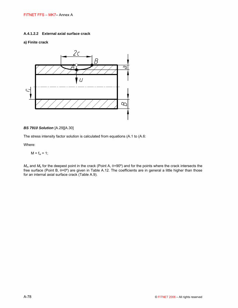
FITNET FFS – MK7– Annex A
A-78 © FITNET 2006 – All rights reserved
A.4.1.2.2 External axial surface crack
a) Finite crack
BS 7910 Solution [A.29][A.30] The stress intensity factor solution is calculated from equations (A.1 to (A.6: Where:
M = fw = 1;
Mm and Mb for the deepest point in the crack (Point A, θ=90º) and for the points where the crack intersects the free surface (Point B, θ=0º) are given in Table A.12. The coefficients are in general a little higher than those for an internal axial surface crack (Table A.9).

(01 May 2006) FITNET MK7
© FITNET 2006– All rights reserved A-79
Table A.12 BS 7910 solutions for Mm and Mb for an axial external surface crack in a cylinder
a/2c = 0.5, B/ri = 0.1 a/2c = 0.5, B/ri = 0.25 a/B Mm(A) Mb(A) Mm(B) Mb(B) a/B Mm(A) Mb(A) Mm(B) Mb(B)
0.0 0.663 0.663 0.729 0.729 0.0 0.663 0.663 0.729 0.729 0.2 0.653 0.470 0.736 0.685 0.2 0.656 0.473 0.741 0.689 0.4 0.675 0.301 0.783 0.666 0.4 0.683 0.307 0.793 0.673 0.6 0.695 0.122 0.846 0.649 0.6 0.710 0.131 0.864 0.659 0.8 0.712 -0.068 0.926 0.634 0.8 0.736 -0.055 0.954 0.647
a/2c = 0.2, B/ri = 0.1 a/2c = 0.2, B/ri = 0.25 0.0 0.951 0.951 0.662 0.662 0.0 0.951 0.951 0.662 0.662 0.2 0.953 0.716 0.685 0.641 0.2 0.964 0.726 0.689 0.644 0.4 1.077 0.561 0.799 0.673 0.4 1.110 0.582 0.806 0.678 0.6 1.213 0.377 0.970 0.715 0.6 1.289 0.417 0.982 0.721 0.8 1.361 0.167 1.198 0.769 0.8 1.502 0.230 1.217 0.775
a/2c = 0.1, B/ri = 0.1 a/2c = 0.1, B/ri = 0.25 0.0 1.059 1.059 0.521 0.521 0.0 1.059 1.059 0.521 0.521 0.2 1.092 0.831 0.583 0.552 0.2 1.106 0.844 0.583 0.552 0.4 1.370 0.750 0.706 0.606 0.4 1.410 0.776 0.693 0.598 0.6 1.735 0.644 0.912 0.681 0.6 1.838 0.693 0.867 0.659 0.8 2.188 0.514 1.202 0.780 0.8 2.390 0.595 1.105 0.736
a/2c = 0.05, B/ri = 0.1 a/2c = 0.05, B/ri = 0.25 0.0 1.103 1.103 0.384 0.384 0.0 1.103 1.103 0.384 0.384 0.2 1.206 0.926 0.455 0.432 0.2 1.222 0.939 0.455 0.432 0.4 1.624 0.923 0.592 0.510 0.4 1.672 0.955 0.581 0.504 0.6 2.295 0.957 0.853 0.643 0.6 2.432 1.029 0.811 0.622 0.8 3.360 1.108 1.305 0.857 0.8 3.670 1.128 1.199 0.809
a/2c = 0.025, B/ri = 0.1 a/2c = 0.025, B/ri = 0.25 0.0 1.120 1.120 0.275 0.275 0.0 1.120 1.120 0.275 0.275 0.2 1.266 0.976 0.338 0.321 0.2 1.282 0.991 0.338 0.321 0.4 1.849 1.075 0.477 0.412 0.4 1.753 1.011 0.468 0.407 0.6 2.628 1.349 0.796 0.602 0.6 2.581 1.107 0.757 0.583 0.8 4.090 1.549 1.471 0.972 0.8 3.839 1.153 1.352 0.918
Validity limits: 0 ≤ a/B ≤ 0.8 0.025 ≤ a/2c ≤ 0.5 0.1 ≤ B/ri ≤ 0.25 2c/W ≤ 0.15 R6 Solution [A.18][A.31] Solutions are given in the form of tables for B/ri ratios of between 0.1 and 0.25 and a/2c ratios of 0.1 and 0.5, for positions θ=90 (Point A) and θ=0º (Point B). The stress intensity factor KI is given by:
π σ=
⎛ ⎞+ ⎜ ⎟
⎝ ⎠∑
3
0, ,2I i i
i i
a a BK a fB c r
(A.68)

FITNET FFS – MK7– Annex A
A-80 © FITNET 2006 – All rights reserved
Pi (i = 0 to 3) are stress components which define the stress distribution P according to
( )3
0
0i
ii
uu for u aa
σ σ σ=
⎛ ⎞= = ≤ ≤⎜ ⎟⎝ ⎠
∑ (A.69)
where P is to be taken normal to the prospective crack plane in an uncracked cylinder. The co-ordinate u is the distance from the external surface of the cylinder. The geometry functions fi (i = 0 to 3) are given in Table A.13 and Table A.14 for the deepest point of the crack (A), and at the intersection of the crack with the free surface (B), respectively.

(01 May 2006) FITNET MK7
© FITNET 2006– All rights reserved A-81
Table A.13 R6 Geometry functions at Point A for a finite external axial surface crack in a cylinder
a/2c=0.5, B/ri=0.25
a/B
0 0.659 0.471 0.387 0.3370.2 0.656 0.459 0.377 0.327 0.5 0.697 0.473 0.384 0.331 0.8 0.736 0.495 0.398 0.342
a/2c=0.5, B/ri=0.1
a/B
0 0.659 0.471 0.387 0.3370.2 0.653 0.457 0.376 0.327 0.5 0.687 0.470 0.382 0.330 0.8 0.712 0.487 0.394 0.340
a/2c=0.2, B/ri=0.25
a/B
0 0.939 0.580 0.434 0.3530.2 0.964 0.596 0.461 0.387 0.5 1.183 0.672 0.500 0.410 0.8 1.502 0.795 0.568 0.455
a/2c=0.2, B/ri=0.1
a/B
0 0.939 0.580 0.434 0.3530.2 0.953 0.591 0.459 0.386 0.5 1.139 0.656 0.491 0.405 0.8 1.361 0.746 0.543 0.439
a/2c=0.1, B/ri=0.25
a/B
0 1.053 0.606 0.443 0.3570.2 1.107 0.658 0.499 0.413 0.5 1.562 0.820 0.584 0.465 0.8 2.390 1.122 0.745 0.568
a/2c=0.1, B/ri=0.1
a/B
0 1.053 0.606 0.443 0.3570.2 1.092 0.652 0.496 0.411 0.5 1.508 0.799 0.571 0.457 0.8 2.188 1.047 0.704 0.541

FITNET FFS – MK7– Annex A
A-82 © FITNET 2006 – All rights reserved
Table A.14 Geometry functions at Point B for a finite external axial surface crack in a cylinder.
a/2c=0.5, B/ri=0.25
a/B
0 0.716 0.118 0.041 0.0220.2 0.741 0.130 0.049 0.026 0.5 0.819 0.155 0.061 0.033 0.8 0.954 0.192 0.078 0.041
a/2c=0.5, B/ri=0.1
a/B
0 0.716 0.118 0.041 0.0220.2 0.736 0.129 0.048 0.025 0.5 0.807 0.150 0.059 0.031 0.8 0.926 0.182 0.072 0.038
a/2c=0.2, B/ri=0.25
a/B
0 0.673 0.104 0.032 0.0150.2 0.690 0.113 0.039 0.019 0.5 0.864 0.170 0.068 0.036 0.8 1.217 0.277 0.117 0.064
a/2c=0.2, B/ri=0.1
a/B
0 0.673 0.104 0.032 0.0150.2 0.685 0.111 0.039 0.019 0.5 0.856 0.167 0.066 0.035 0.8 1.198 0.269 0.112 0.061
a/2c =0.1, B/ri=0.25
a/B
0 0.516 0.069 0.017 0.0090.2 0.583 0.076 0.022 0.010 0.5 0.748 0.128 0.047 0.024 0.8 1.105 0.230 0.092 0.049
a/2c=0.1, B/ri=0.1
a/t
0 0.516 0.069 0.017 0.0090.2 0.583 0.076 0.022 0.010 0.5 0.768 0.135 0.051 0.027 0.8 1.202 0.264 0.109 0.059
Plots

(01 May 2006) FITNET MK7
© FITNET 2006– All rights reserved A-83
Figure A.16 shows solutions (BS 7910, R6 and selected API solutions) for various a/2c ratios, with B/ri=0.10 and 0.25. For geometries outside the B/ri validity limits described in this section, a possible approach is to use the BS 7910 flat plate solution multiplied by a bulging factor as given by equation (A.55 and (A.56. This tends to overestimate the stress intensity relative to the solutions shown in this section.

FITNET FFS – MK7– Annex A
A-84 © FITNET 2006 – All rights reserved
Figure A.16 Normalised K-solution for an external axial crack in a cylinder
External axial surface crack in a cylinder, B/ri=0.10, θ=90o
0.0
0.5
1.0
1.5
2.0
2.5
3.0
3.5
4.0
4.5
0.0 0.1 0.2 0.3 0.4 0.5 0.6 0.7 0.8a/B
Mm
(d)
BS, a/2c=0.025
BS, a/2c=0.05
BS, a/2c=0.10
BS, a/2c=0.20
BS, a/2c=0.50
R6, a/2c=0.10
R6, a/2c=0.20
R6, a/2c=0.50
API, a/2c=0.10
a) Membrane stress, B/ri=0.1, θ=90º
External axial surface crack in a cylinder, B/ri=0.10, θ=0o
0.0
0.2
0.4
0.6
0.8
1.0
1.2
1.4
1.6
0.0 0.1 0.2 0.3 0.4 0.5 0.6 0.7 0.8a/B
Mm
(s)
BS, a/2c=0.025 BS, a/2c=0.05
BS, a/2c=0.10 BS, a/2c=0.20
BS, a/2c=0.50 R6, a/2c=0.10
R6, a/2c=0.20 R6, a/2c=0.50
b) Membrane stress, B/ri=0.1, θ=0º

(01 May 2006) FITNET MK7
© FITNET 2006– All rights reserved A-85
Normalised K-solution for an external axial crack in a cylinder (cont’d)
External axial surface crack in a cylinder, B/ri=0.10, θ=90o
-0.2
0.0
0.2
0.4
0.6
0.8
1.0
1.2
1.4
1.6
0.0 0.1 0.2 0.3 0.4 0.5 0.6 0.7 0.8a/B
Mb(
d)
BS, a/2c=0.025BS, a/2c=0.05BS, a/2c=0.10BS, a/2c=0.20BS, a/2c=0.50R6, a/2c=0.10R6, a/2c=0.20R6, a/2c=0.50
c) Bending stress, B/ri=0.1, θ=90º
External axial surface crack in a cylinder, B/ri=0.10, θ=0o
0.2
0.3
0.4
0.5
0.6
0.7
0.8
0.9
1.0
0.0 0.1 0.2 0.3 0.4 0.5 0.6 0.7 0.8a/B
Mb(
s)
BS, a/2c=0.025BS, a/2c=0.05BS, a/2c=0.10BS, a/2c=0.20BS, a/2c=0.50R6, a/2c=0.10R6, a/2c=0.20R6, a/2c=0.50
d) Bending stress, B/ri=0.1, θ=0º
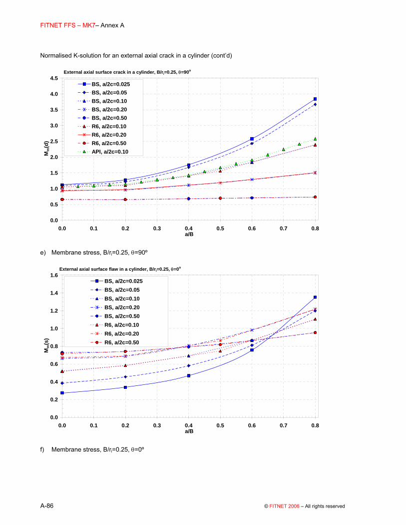
FITNET FFS – MK7– Annex A
A-86 © FITNET 2006 – All rights reserved
Normalised K-solution for an external axial crack in a cylinder (cont’d)
0.0
0.5
1.0
1.5
2.0
2.5
3.0
3.5
4.0
4.5
0.0 0.1 0.2 0.3 0.4 0.5 0.6 0.7 0.8a/B
Mm
(d)
BS, a/2c=0.025BS, a/2c=0.05BS, a/2c=0.10BS, a/2c=0.20BS, a/2c=0.50R6, a/2c=0.10R6, a/2c=0.20R6, a/2c=0.50API, a/2c=0.10
External axial surface crack in a cylinder, B/ri=0.25, θ=90o
e) Membrane stress, B/ri=0.25, θ=90º
0.0
0.2
0.4
0.6
0.8
1.0
1.2
1.4
1.6
0.0 0.1 0.2 0.3 0.4 0.5 0.6 0.7 0.8a/B
Mm
(s)
BS, a/2c=0.025BS, a/2c=0.05BS, a/2c=0.10BS, a/2c=0.20BS, a/2c=0.50R6, a/2c=0.10R6, a/2c=0.20R6, a/2c=0.50
External axial surface flaw in a cylinder, B/ri=0.25, θ=0o
f) Membrane stress, B/ri=0.25, θ=0º

(01 May 2006) FITNET MK7
© FITNET 2006– All rights reserved A-87
Normalised K-solution for an external axial crack in a cylinder (contd’)
-0.2
0.0
0.2
0.4
0.6
0.8
1.0
1.2
1.4
1.6
0.0 0.1 0.2 0.3 0.4 0.5 0.6 0.7 0.8a/B
Mb(
d)
BS, a/2c=0.025BS, a/2c=0.05BS, a/2c=0.10BS, a/2c=0.20BS, a/2c=0.50R6, a/2c=0.10R6, a/2c=0.20R6, a/2c=0.50
External axial surface flaw in a cylinder, B/ri=0.25, θ=90o
g) Bending stress, B/ri=0.25, θ=90º
0.2
0.3
0.4
0.5
0.6
0.7
0.8
0.9
1.0
0.0 0.1 0.2 0.3 0.4 0.5 0.6 0.7 0.8a/B
Mb(
s)
BS, a/2c=0.025BS, a/2c=0.05BS, a/2c=0.10BS, a/2c=0.20BS, a/2c=0.50R6, a/2c=0.10R6, a/2c=0.20R6, a/2c=0.50
External axial surface flaw in a cylinder, B/ri=0.25, θ=0o
h) Bending stress, B/ri=0.25, θ=0º

FITNET FFS – MK7– Annex A
A-88 © FITNET 2006 – All rights reserved
b) Extended crack
BS 7910 Solution [A.32][A.33] The stress intensity factor solution is calculated from equations (A.1 to (A.6: Where:
M = fw = 1;
Mm and Mb are given in Table A.15 (note that this is identical to Table A.10, ie BS 7910 assumes the same solutions for long external and long internal axial flaws), and specifically states M=1, ie no bulging correction factor should be applied.
Table A.15 BS 7910 solutions for Mm and Mb for an extended axial crack in a cylinder
B/ri = 0.1 B/ri = 0.25 a/B Mm Mb a/B Mm Mb 0.0 1.122 1.122 0.0 1.122 1.122 0.2 1.380 1.018 0.2 1.304 1.002 0.4 1.930 1.143 0.4 1.784 1.033 0.6 2.960 1.484 0.6 2.566 1.094 0.8 4.820 1.990 0.8 3.461 0.949
Validity limits: 0.0 ≤ a/B ≤ 0.8 0.1 ≤B/ri ≤ 0.25 R6 Solution [A.34] a closed form solution is not given; the solution is provided in integral form, covering B/ri ratios between 0.25 and 2. Alternative solutions are cited for thinner-walled cylinders. Plots Figure A.17 compares the solutions recommended by BS, R6 and API. A BS 7910 flat plate solution for a fully extended surface flaw (cf Figure A.3) is shown for comparison. Note that both the API and R6 solutions show a higher value of Mm for external than for internal flaws (cf Figure A.15). The R6 solutions are recommended.

(01 May 2006) FITNET MK7
© FITNET 2006– All rights reserved A-89
Figure A.17 Normalised K-solution for an extended external axial crack in a cylinder
Extended external axial crack in a cylinder
1.0
2.0
3.0
4.0
5.0
6.0
0.0 0.1 0.2 0.3 0.4 0.5 0.6 0.7 0.8a/B
Mm
BS, B/ri=0.10BS, B/ri=0.25R6, B/ri=0.25API, B/ri=0.10API, B/ri=0.20Flat plate
a) Membrane stress
Extended external axial crack in a cylinder
0.9
1.1
1.3
1.5
1.7
1.9
0.0 0.1 0.2 0.3 0.4 0.5 0.6 0.7 0.8a/B
Mb
Flat plateAPI, B/ri=0.10BS, B/ri=0.10API, B/ri=0.20BS, B/ri=0.25R6, B/ri=0.25
b) Bending stress
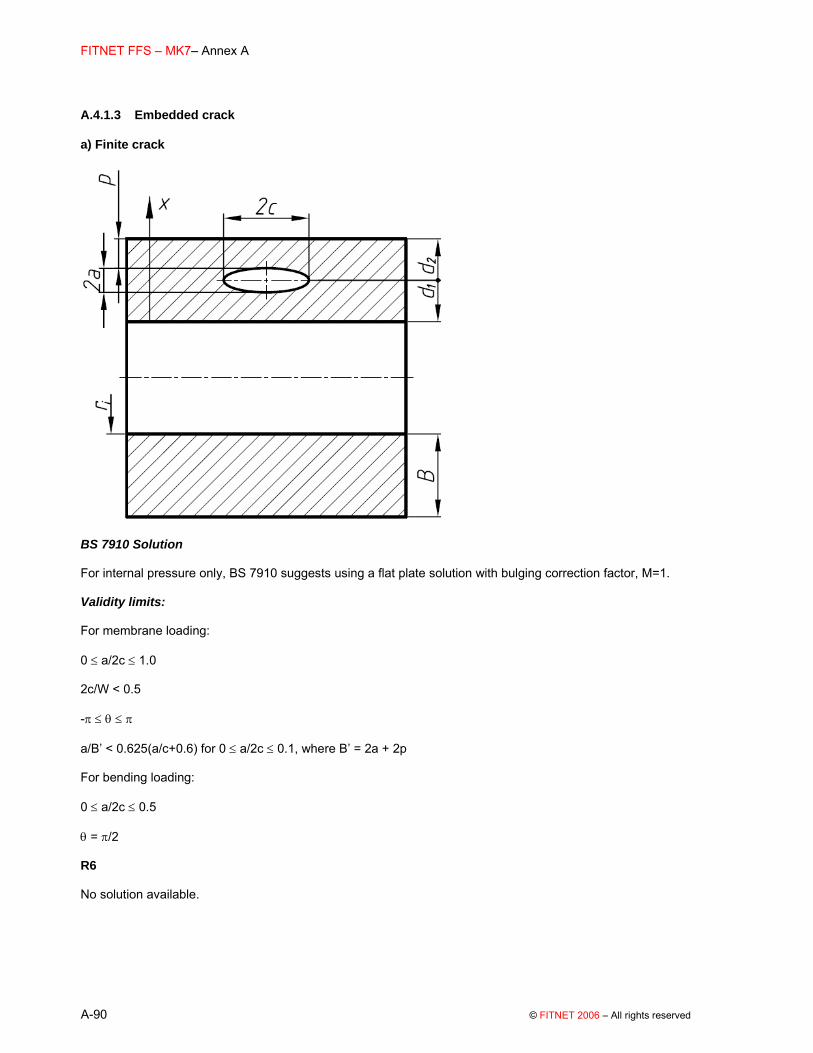
FITNET FFS – MK7– Annex A
A-90 © FITNET 2006 – All rights reserved
A.4.1.3 Embedded crack
a) Finite crack
BS 7910 Solution For internal pressure only, BS 7910 suggests using a flat plate solution with bulging correction factor, M=1. Validity limits: For membrane loading: 0 ≤ a/2c ≤ 1.0 2c/W < 0.5 -π ≤ θ ≤ π a/B’ < 0.625(a/c+0.6) for 0 ≤ a/2c ≤ 0.1, where B’ = 2a + 2p For bending loading: 0 ≤ a/2c ≤ 0.5 θ = π/2 R6 No solution available.
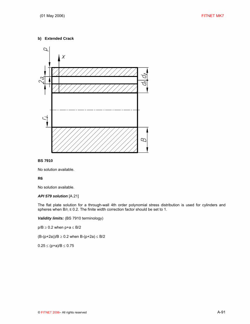
(01 May 2006) FITNET MK7
© FITNET 2006– All rights reserved A-91
b) Extended Crack
BS 7910 No solution available. R6 No solution available. API 579 solution [A.21] The flat plate solution for a through-wall 4th order polynomial stress distribution is used for cylinders and spheres when B/ri ≤ 0.2. The finite width correction factor should be set to 1. Validity limits: (BS 7910 terminology) p/B ≥ 0.2 when p+a ≤ B/2 (B-(p+2a))/B ≥ 0.2 when B-(p+2a) ≤ B/2 0.25 ≤ (p+a)/B ≤ 0.75

FITNET FFS – MK7– Annex A
A-92 © FITNET 2006 – All rights reserved
A.4.2 Pipes or Cylinders with Circumferential Cracks
A.4.2.1 Through-thickness crack
BS 7910 Solution: [A.28] The stress intensity factor solution is calculated from equations (A.1 to (A.6 Where: KI = KI
pressure + KIbending;
M = 1; Mm = M1 + M2 at the outside surface, M1 - M2 at the inside surface Mb = M3 + M4 at the outside surface, M3 – M4 at the inside surface where KI
pressure and KIbending are calculated from equations (A.1 to (A.6 and represent, respectively, contributions to KI
of pressure-induced membrane stresses and through-wall bending stresses. The coefficients M1 – M4 are given in Table A.16 for pressure and bending loading, in terms of the parameter λ referred to in equation (A.59. For membrane loading, Pm should be multiplied by a factor of β, where:
0.52 tan
2 m
r a = a r
β⎧ ⎫⎛ ⎞⎪ ⎪⎨ ⎬⎜ ⎟⎪ ⎪⎝ ⎠⎩ ⎭
(A.70)

(01 May 2006) FITNET MK7
© FITNET 2006– All rights reserved A-93
Table A.16 BS 7910 Solution for circumferential through-thickness cracks in cylinders
a) M1 for Pressure loading
Parameter, λ B/rm=0.2 B/rm=0.1 B/rm=0.05 B/rm=0.02 B/rm=0.01
0.000 1.000 1.000 1.000 1.000 1.000 0.177 1.248 0.251 1.032 0.355 1.290 1.050 0.502 1.066 0.561 1.061 0.709 1.085 0.793 1.088 1.064 1.406 1.122 1.096 1.505 1.192 1.586 1.139 1.596 1.522 2.128 1.276 2.257 1.324 2.306 1.723 3.193 2.044 1.469 3.261 1.545 3.365 1.378 3.902 2.367 4.515 1.864 4.612 1.752 4.759 1.425 4.789 2.883 5.498 3.414 5.518 2.164 6.385 4.301 2.140 6.772 2.641 7.139 1.732 7.776 3.117 7.804 2.495 9.032 3.917 9.578 3.040
10.096 2.588 10.997 3.580 12.770 4.502 15.143 3.623

FITNET FFS – MK7– Annex A
A-94 © FITNET 2006 – All rights reserved
b) M2 for Pressure loading
Parameter, λ B/rm=0.2 B/rm=0.1 B/rm=0.05 B/rm=0.02 B/rm=0.01
0.000 0.000 0.000 0.000 0.000 0.000 0.177 0.069 0.251 0.035 0.355 0.077 0.034 0.502 0.057 0.561 0.045 0.709 0.069 0.793 0.063 1.064 0.140 1.122 0.087 1.505 0.121 1.586 0.102 1.596 0.153 2.128 0.116 2.257 0.108 2.306 0.112 3.193 −0.014 0.041 3.261 0.019 3.365 0.043 3.902 −0.158 4.515 −0.153 4.612 −0.119 4.759 −0.082 4.789 −0.385 5.498 −0.622 5.518 −0.328 6.385 −1.015 −0.318 6.772 −0.528 7.139 −0.277 7.776 −0.747 7.804 −0.485 9.032 −1.071 9.578 −0.762
10.096 −0.585 10.997 −0.944 12.770 −1.281 15.143 −1.126

(01 May 2006) FITNET MK7
© FITNET 2006– All rights reserved A-95
c) M3 for Bending loading
Parameter, λ B/rm=0.2 B/rm=0.1 B/rm=0.05 B/rm=0.02 B/rm=0.01
0.000 0.000 0.000 0.000 0.000 0.000 0.177 0.023 0.251 0.021 0.355 0.037 0.015 0.502 0.028 0.561 0.013 0.709 0.025 0.793 0.012 1.064 0.064 1.122 0.026 1.505 0.054 1.586 0.025 1.596 0.079 2.128 0.048 2.257 0.063 2.306 0.092 3.193 0.106 0.052 3.261 0.069 3.365 0.043 3.902 0.117 4.515 0.074 4.612 0.052 4.759 0.032 4.789 0.135 5.498 0.156 5.518 0.079 6.385 0.191 0.054 6.772 0.088 7.139 0.033 7.776 0.100 7.804 0.059 9.032 0.119 9.578 0.065
10.096 0.046 10.997 0.068 12.770 0.078 15.143 0.029

FITNET FFS – MK7– Annex A
A-96 © FITNET 2006 – All rights reserved
d) M4 for Bending loading
Parameter, λ B/rm=0.2 B/rm=0.1 B/rm=0.05 B/rm=0.02 B/rm=0.01
0.000 1.000 1.000 1.000 1.000 1.000 0.177 0.918 0.251 0.828 0.355 0.816 0.750 0.502 0.733 0.561 0.673 0.709 0.666 0.793 0.633 1.064 0.624 1.122 0.587 1.505 0.544 1.586 0.544 1.596 0.533 2.128 0.465 2.257 0.450 2.306 0.441 3.193 0.361 0.373 3.261 0.364 3.365 0.364 3.902 0.315 4.515 0.299 4.612 0.301 4.759 0.293 4.789 0.270 5.498 0.239 5.518 0.264 6.385 0.203 0.249 6.772 0.230 7.139 0.228 7.776 0.205 7.804 0.218 9.032 0.179 9.578 0.187
10.096 0.184 10.997 0.182 12.770 0.161 15.143 0.205

(01 May 2006) FITNET MK7
© FITNET 2006– All rights reserved A-97
Validity limits: Range of application: 0 ≤ λ ≤ 15.143 0.01 ≤ B/rm ≤0.2 R6 solution [A.7][A.35] The R6 solution is based on similar work to that described for the BS 7910 solution, although it is presented in a slightly different way. Consequently it is not repeated here. Plots Figure A.18 shows the solution as a function of λ (defined in (A.59) for various B/rm ratios.

FITNET FFS – MK7– Annex A
A-98 © FITNET 2006 – All rights reserved
Figure A.18 Normalised K-solution for a circumferential through-thickness crack in a cylinder
Circumferential through-thickness crack in a cylinder
0.5
1.0
1.5
2.0
2.5
3.0
3.5
4.0
0.0 2.0 4.0 6.0 8.0 10.0 12.0 14.0 16.0λ
Mm
(out
side
)
BS, B/r=0.2 R6, B/r=0.2
BS, B/r=0.1 R6, B/r=0.1
BS, B/r=0.05 R6, B/r=0.05
BS, B/r=0.02 R6, B/r=0.02
BS, B/r=0.01 R6, B/r=0.01
a) Mm on the outside of the cylinder
Circumferential through-thickness crack in a cylinder
0.00.51.01.52.02.53.03.54.04.55.05.56.06.57.0
0.0 2.0 4.0 6.0 8.0 10.0 12.0 14.0 16.0λ
Mm
(ins
ide)
BS, B/r=0.2 R6, B/r=0.2BS, B/r=0.1 R6, B/r=0.1BS, B/r=0.05 R6, B/r=0.05BS, B/r=0.02 R6, B/r=0.02BS, B/r=0.01 R6, B/r=0.01
b) Mm on the inside of the cylinder
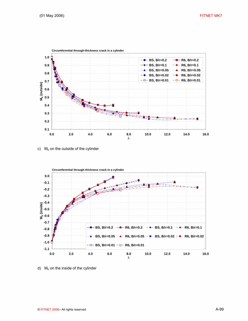
(01 May 2006) FITNET MK7
© FITNET 2006– All rights reserved A-99
Circumferential through-thickness crack in a cylinder
0.1
0.2
0.3
0.4
0.5
0.6
0.7
0.8
0.9
1.0
0.0 2.0 4.0 6.0 8.0 10.0 12.0 14.0 16.0λ
Mb (
outs
ide)
BS, B/r=0.2 R6, B/r=0.2BS, B/r=0.1 R6, B/r=0.1BS, B/r=0.05 R6, B/r=0.05BS, B/r=0.02 R6, B/r=0.02BS, B/r=0.01 R6, B/r=0.01
c) Mb on the outside of the cylinder
Circumferential through-thickness crack in a cylinder
-1.1
-1.0
-0.9
-0.8
-0.7
-0.6
-0.5
-0.4
-0.3
-0.2
-0.1
0.0
0.0 2.0 4.0 6.0 8.0 10.0 12.0 14.0 16.0λ
Mb (
insi
de)
BS, B/r=0.2 R6, B/r=0.2 BS, B/r=0.1 R6, B/r=0.1
BS, B/r=0.05 R6, B/r=0.05 BS, B/r=0.02 R6, B/r=0.02
BS, B/r=0.01 R6, B/r=0.01
d) Mb on the inside of the cylinder

FITNET FFS – MK7– Annex A
A-100 © FITNET 2006 – All rights reserved
A.4.2.2 Surface cracks
A.4.2.2.1 Internal circumferential surface crack
a) Finite crack
BS 7910 Solution: [A.15][A.29][A.36][A.37] The stress intensity factor solution is calculated from equations (A.1 to (A.6 Where:
M = fw = 1
Mm and Mb for the deepest point in the crack (A, θ=90º) and for the points where the crack intersects the free surface (B, θ=0º) are given in Table A.17.
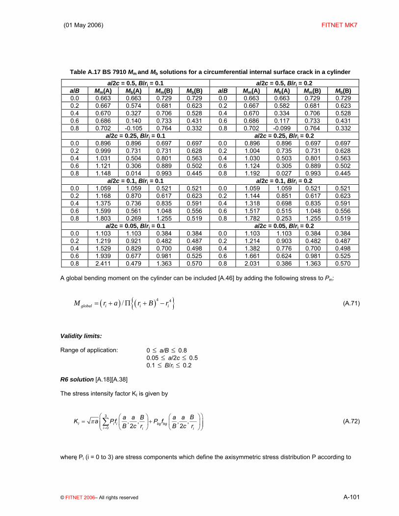
(01 May 2006) FITNET MK7
© FITNET 2006– All rights reserved A-101
Table A.17 BS 7910 Mm and Mb solutions for a circumferential internal surface crack in a cylinder
a/2c = 0.5, B/ri = 0.1 a/2c = 0.5, B/ri = 0.2 a/B Mm(A) Mb(A) Mm(B) Mb(B) a/B Mm(A) Mb(A) Mm(B) Mb(B) 0.0 0.663 0.663 0.729 0.729 0.0 0.663 0.663 0.729 0.729 0.2 0.667 0.574 0.681 0.623 0.2 0.667 0.582 0.681 0.623 0.4 0.670 0.327 0.706 0.528 0.4 0.670 0.334 0.706 0.528 0.6 0.686 0.140 0.733 0.431 0.6 0.686 0.117 0.733 0.431 0.8 0.702 -0.105 0.764 0.332 0.8 0.702 -0.099 0.764 0.332
a/2c = 0.25, B/ri = 0.1 a/2c = 0.25, B/ri = 0.2 0.0 0.896 0.896 0.697 0.697 0.0 0.896 0.896 0.697 0.697 0.2 0.999 0.731 0.731 0.628 0.2 1.004 0.735 0.731 0.628 0.4 1.031 0.504 0.801 0.563 0.4 1.030 0.503 0.801 0.563 0.6 1.121 0.306 0.889 0.502 0.6 1.124 0.305 0.889 0.502 0.8 1.148 0.014 0.993 0.445 0.8 1.192 0.027 0.993 0.445
a/2c = 0.1, B/ri = 0.1 a/2c = 0.1, B/ri = 0.2 0.0 1.059 1.059 0.521 0.521 0.0 1.059 1.059 0.521 0.521 0.2 1.168 0.870 0.617 0.623 0.2 1.144 0.851 0.617 0.623 0.4 1.375 0.736 0.835 0.591 0.4 1.318 0.698 0.835 0.591 0.6 1.599 0.561 1.048 0.556 0.6 1.517 0.515 1.048 0.556 0.8 1.803 0.269 1.255 0.519 0.8 1.782 0.253 1.255 0.519
a/2c = 0.05, B/ri = 0.1 a/2c = 0.05, B/ri = 0.2 0.0 1.103 1.103 0.384 0.384 0.0 1.103 1.103 0.384 0.384 0.2 1.219 0.921 0.482 0.487 0.2 1.214 0.903 0.482 0.487 0.4 1.529 0.829 0.700 0.498 0.4 1.382 0.776 0.700 0.498 0.6 1.939 0.677 0.981 0.525 0.6 1.661 0.624 0.981 0.525 0.8 2.411 0.479 1.363 0.570 0.8 2.031 0.386 1.363 0.570
A global bending moment on the cylinder can be included [A.46] by adding the following stress to Pm:
( ) ( ){ }4 4/global i i iM r a r B r= + Π + − (A.71)
Validity limits: Range of application: 0 ≤ a/B ≤ 0.8 0.05 ≤ a/2c ≤ 0.5 0.1 ≤ B/ri ≤ 0.2 R6 solution [A.18][A.38] The stress intensity factor KI is given by
3
0, , , ,2 2I i i bg bg
i i i
Ba a B a aK a Pf P fB c r B c r
π=
⎛ ⎞⎛ ⎞ ⎛ ⎞= +⎜ ⎟⎜ ⎟ ⎜ ⎟⎜ ⎟⎝ ⎠ ⎝ ⎠⎝ ⎠
∑ (A.72)
where Pi (i = 0 to 3) are stress components which define the axisymmetric stress distribution P according to

FITNET FFS – MK7– Annex A
A-102 © FITNET 2006 – All rights reserved
( )3
0 for 0
i
ii
uP P u P u aa=
⎛ ⎞= = ≤ ≤⎜ ⎟⎝ ⎠
∑ (A.73)
and Pbg is the global bending stress, ie the maximum outer fibre bending stress. The stresses P and Pbg are to be taken normal to the prospective crack plane in an uncracked cylinder. The co-ordinate u is the distance from the inner surface of the cylinder as defined in the figure above. The solution for the global bending stress assumes that the crack is symmetrically positioned about the global bending axis so that the maximum stress occurs at u=B above Point A. The geometry functions fi (i = 0 to 3) and fbg are given in Table A.18 and for the deepest point of the crack (A), and at the intersection of the crack with the free surface (B), respectively.

(01 May 2006) FITNET MK7
© FITNET 2006– All rights reserved A-103
Table A.18 R6 Geometry functions at Point A for a part circumferential internal surface crack in a cylinder.
a/2c=0.5, B/ri=0.2
a/B 0 0.659 0.471 0.387 0.337 0.549
0.2 0.665 0.460 0.371 0.316 0.570 0.4 0.682 0.471 0.381 0.327 0.600 0.6 0.700 0.481 0.390 0.335 0.632 0.8 0.729 0.506 0.410 0.352 0.675
a/2c=0.5, B/ri=0.1
a/B 0 0.659 0.471 0.387 0.337 0.599
0.2 0.664 0.459 0.370 0.315 0.613 0.4 0.680 0.469 0.379 0.325 0.636 0.6 0.696 0.478 0.387 0.333 0.659 0.8 0.714 0.497 0.403 0.347 0.685
a/2c=0.25, B/ri=0.2
a/B 0 0.886 0.565 0.430 0.352 0.738
0.2 0.890 0.556 0.424 0.347 0.761 0.4 0.934 0.576 0.440 0.362 0.817 0.6 0.991 0.602 0.457 0.377 0.885 0.8 1.066 0.653 0.496 0.409 0.973
a/2c=0.25, B/ri=0.1
a/B 0 0.886 0.565 0.430 0.352 0.806
0.2 0.895 0.557 0.424 0.347 0.825 0.4 0.947 0.580 0.441 0.363 0.883 0.6 1.008 0.605 0.458 0.377 0.950 0.8 1.062 0.647 0.492 0.406 1.012
a/2c=0.125, B/ri=0.2
a/B 0 1.025 0.600 0.441 0.356 0.854
0.2 1.041 0.625 0.469 0.381 0.890 0.4 1.142 0.666 0.496 0.403 0.995 0.6 1.274 0.718 0.527 0.427 1.126 0.8 1.463 0.813 0.589 0.471 1.310
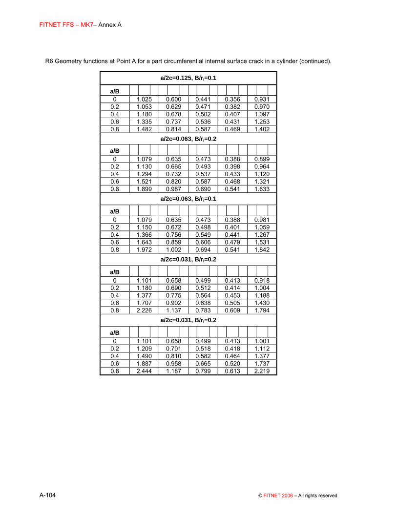
FITNET FFS – MK7– Annex A
A-104 © FITNET 2006 – All rights reserved
R6 Geometry functions at Point A for a part circumferential internal surface crack in a cylinder (continued).
a/2c=0.125, B/ri=0.1
a/B 0 1.025 0.600 0.441 0.356 0.931
0.2 1.053 0.629 0.471 0.382 0.970 0.4 1.180 0.678 0.502 0.407 1.097 0.6 1.335 0.737 0.536 0.431 1.253 0.8 1.482 0.814 0.587 0.469 1.402
a/2c=0.063, B/ri=0.2
a/B 0 1.079 0.635 0.473 0.388 0.899
0.2 1.130 0.665 0.493 0.398 0.964 0.4 1.294 0.732 0.537 0.433 1.120 0.6 1.521 0.820 0.587 0.468 1.321 0.8 1.899 0.987 0.690 0.541 1.633
a/2c=0.063, B/ri=0.1
a/B 0 1.079 0.635 0.473 0.388 0.981
0.2 1.150 0.672 0.498 0.401 1.059 0.4 1.366 0.756 0.549 0.441 1.267 0.6 1.643 0.859 0.606 0.479 1.531 0.8 1.972 1.002 0.694 0.541 1.842
a/2c=0.031, B/ri=0.2
a/B 0 1.101 0.658 0.499 0.413 0.918
0.2 1.180 0.690 0.512 0.414 1.004 0.4 1.377 0.775 0.564 0.453 1.188 0.6 1.707 0.902 0.638 0.505 1.430 0.8 2.226 1.137 0.783 0.609 1.794
a/2c=0.031, B/ri=0.2
a/B 0 1.101 0.658 0.499 0.413 1.001
0.2 1.209 0.701 0.518 0.418 1.112 0.4 1.490 0.810 0.582 0.464 1.377 0.6 1.887 0.958 0.665 0.520 1.737 0.8 2.444 1.187 0.799 0.613 2.219

(01 May 2006) FITNET MK7
© FITNET 2006– All rights reserved A-105
Table A.19 R6 Geometry functions at Point B for a part circumferential internal surface crack in a cylinder
a/2c=0.5, B/ri = 0.2 a/B
0 0.718 0.117 0.041 0.020 0.598
0.2 0.746 0.125 0.046 0.023 0.625 0.4 0.774 0.133 0.051 0.026 0.652 0.6 0.822 0.147 0.058 0.031 0.696 0.8 0.876 0.161 0.064 0.034 0.746
a/2c=0.5, B/ri = 0.1 a/B
0 0.716 0.116 0.041 0.020 0.652
0.2 0.747 0.125 0.046 0.023 0.682 0.4 0.778 0.134 0.051 0.026 0.712 0.6 0.831 0.148 0.058 0.031 0.763 0.8 0.890 0.163 0.064 0.033 0.820
a/2c=0.25, B/ri = 0.2 a/B
0 0.664 0.091 0.029 0.013 0.555
0.2 0.716 0.108 0.039 0.019 0.599 0.4 0.768 0.125 0.049 0.025 0.643 0.6 0.852 0.152 0.062 0.033 0.712 0.8 0.944 0.179 0.075 0.040 0.788
a/2c=0.25, B/ri = 0.1 a/B
0 0.657 0.089 0.030 0.014 0.598
0.2 0.719 0.109 0.040 0.020 0.656 0.4 0.781 0.129 0.050 0.026 0.714 0.6 0.883 0.160 0.066 0.035 0.809 0.8 0.995 0.191 0.079 0.042 0.913
a/2c=0.125, B/ri = 0.2 a/B
0 0.541 0.054 0.014 0.004 0.461
0.2 0.598 0.072 0.023 0.010 0.496 0.4 0.655 0.090 0.032 0.016 0.531 0.6 0.737 0.116 0.045 0.023 0.576 0.8 0.846 0.151 0.062 0.033 0.634
a/2c=0.5, B/ri = 0.2 a/B
0 0.718 0.117 0.041 0.020 0.598
0.2 0.746 0.125 0.046 0.023 0.625 0.4 0.774 0.133 0.051 0.026 0.652 0.6 0.822 0.147 0.058 0.031 0.696 0.8 0.876 0.161 0.064 0.034 0.746

FITNET FFS – MK7– Annex A
A-106 © FITNET 2006 – All rights reserved
R6 Geometry functions at Point B for a part circumferential internal surface crack in a cylinder (continued).
a/2c=0.5, B/ri = 0.1 a/B
0 0.716 0.116 0.041 0.020 0.652
0.2 0.747 0.125 0.046 0.023 0.682 0.4 0.778 0.134 0.051 0.026 0.712 0.6 0.831 0.148 0.058 0.031 0.763 0.8 0.890 0.163 0.064 0.033 0.820
a/2c=0.25, B/ri = 0.2 a/B
0 0.664 0.091 0.029 0.013 0.555
0.2 0.716 0.108 0.039 0.019 0.599 0.4 0.768 0.125 0.049 0.025 0.643 0.6 0.852 0.152 0.062 0.033 0.712 0.8 0.944 0.179 0.075 0.040 0.788
a/2c=0.25, B/ri = 0.1 a/B
0 0.657 0.089 0.030 0.014 0.598
0.2 0.719 0.109 0.040 0.020 0.656 0.4 0.781 0.129 0.050 0.026 0.714 0.6 0.883 0.160 0.066 0.035 0.809 0.8 0.995 0.191 0.079 0.042 0.913
a/2c=0.125, B/ri = 0.2 a/B
0 0.541 0.054 0.014 0.004 0.461
0.2 0.598 0.072 0.023 0.010 0.496 0.4 0.655 0.090 0.032 0.016 0.531 0.6 0.737 0.116 0.045 0.023 0.576 0.8 0.846 0.151 0.062 0.033 0.634
Plots Figure A.19 (x-ref) shows the solutions for various a/2c and B/ri. BSI, R6 and API solutions are included (R6 results were obtained by extrapolation of the tabulated solutions); BSI solutions for a surface crack in a flat plate (infinite radius, B/ri→0) are included for comparison. For the solution at θ=90º (Mm(A) and Mm(B)) R6 and API solutions are very close for a given geometry, with BS 7910 solutions slightly higher. For the surface (Point B, θ=0º), the BS solutions show rather different trends from the others. As has been pointed out by Smith ([A.13], the determination of stress intensity by elastic FEA as the crack front approaches the surface presents particular difficulties, and this may be a factor in the discrepancy.

(01 May 2006) FITNET MK7
© FITNET 2006– All rights reserved A-107
Figure A.19 Normalised K-solution for an internal circumferential crack in a cylinder
0.5
1.0
1.5
2.0
2.5
3.0
3.5
0.0 0.2 0.4 0.6 0.8 1.0a/B
Mm
(d)..
.
BS, a/2c=0.05 BS, a/2c=0.10
BS, a/2c=0.25 BS, a/2c=0.50
R6, a/2c=0.05 (interp) R6, a/2c=0.10 (interp)
R6, a/2c=0.25 R6, a/2c=0.50
API, a/2c=0.05 API, a/2c=0.10
API, a/2c=0.25 API, a/2c=0.50
Flat plate, a/2c=0.05 Flat plate, a/2c=0.50
Internal circumferential surface crack in a cylinder, B/ri=0.10, θ=90o
a) Membrane stress, θ=90º, B/ri=0.1
0.0
0.2
0.4
0.6
0.8
1.0
1.2
1.4
0.0 0.2 0.4 0.6 0.8 1.0a/B
Mm
(s)..
.
BS, a/2c=0.50 API, a/2c=0.50 R6, a/2c=0.50BS, a/2c=0.25 API, a/2c=0.25 R6, a/2c=0.25BS, a/2c=0.10 API, a/2c=0.10 R6, a/2c=0.10 (interp)BS, a/2c=0.05 API, a/2c=0.05 R6, a/2c=0.05 (interp)
Internal circumferential surface crack in a cylinder, B/ri=0.10, θ=0o
b) Membrane stress, θ=0º, B/ri=0.1

FITNET FFS – MK7– Annex A
A-108 © FITNET 2006 – All rights reserved
Normalised K-solution for an internal circumferential crack in a cylinder (cont’d)
-0.2
0.0
0.2
0.4
0.6
0.8
1.0
1.2
0.0 0.2 0.4 0.6 0.8 1.0a/B
Mb(
d)...
BS, a/2c=0.50 API, a/2c=0.50 R6, a/2c=0.50BS, a/2c=0.25 API, a/2c=0.25 R6, a/2c=0.25BS, a/2c=0.10 API, a/2c=0.10 R6, a/2c=0.10 (interp)BS, a/2c=0.05 API, a/2c=0.05 R6, a/2c=0.05 (interp)
Internal circumferential surface crack in a cylinder, B/ri=0.10, θ=90o
c) Bending stress, θ=90º, B/ri=0.1
0.2
0.3
0.4
0.5
0.6
0.7
0.8
0.0 0.2 0.4 0.6 0.8 1.0a/B
Mb(
s)...
BS, a/2c=0.50 API, a/2c=0.50 R6, a/2c=0.50BS, a/2c=0.25 API, a/2c=0.25 R6, a/2c=0.25BS, a/2c=0.10 API, a/2c=0.10 R6, a/2c=0.10 (interp)BS, a/2c=0.05 API, a/2c=0.05 R6, a/2c=0.05 (interp)
Internal circumferential surface crack in a cylinder, B/ri=0.10, θ=0o
d) Bending stress, θ=0º, B/ri=0.1

(01 May 2006) FITNET MK7
© FITNET 2006– All rights reserved A-109
b) Extended crack
BS 7910 Solution [A.36][A.32][A.39]
The stress intensity factor solution is calculated from equations (A.1 to (A.6 Where:
M = fw = 1;
Mm and Mb are given in Table A.20:
Table A.20 BS 7910 Mm and Mb solutions for an extended circumferential internal surface crack in a cylindrical shell
B/ri = 0.1 B/ri = 0.2 a/B Mm Mb a/B Mm Mb 0.0 1.122 1.122 0.0 1.122 1.122 0.2 1.261 0.954 0.2 1.215 0.933 0.4 1.582 0.909 0.4 1.446 0.810 0.6 2.091 0.810 0.6 1.804 0.650 0.8 2.599 0.600 0.8 2.280 0.411
Validity limits:
Range of application: 0 ≤ a/B ≤ 0.8 0.1 ≤ B/ri ≤ 0.2 R6 Solution [A.19] The stress intensity factor KI is given by:
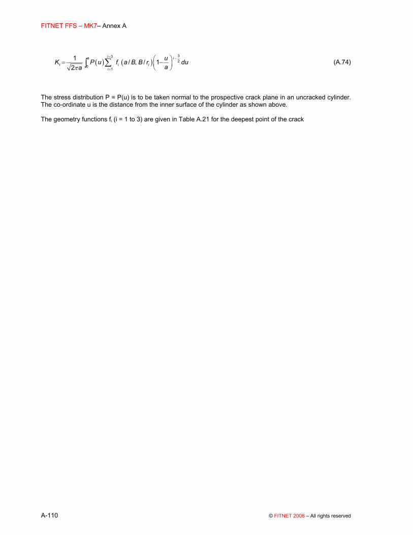
FITNET FFS – MK7– Annex A
A-110 © FITNET 2006 – All rights reserved
( ) ( )π
= −
=
⎛ ⎞= −⎜ ⎟⎝ ⎠
∑∫332
01
1 / , / 12
ia i
I i ii
uK P u f a B B r duaa
(A.74)
The stress distribution P = P(u) is to be taken normal to the prospective crack plane in an uncracked cylinder. The co-ordinate u is the distance from the inner surface of the cylinder as shown above. The geometry functions fi (i = 1 to 3) are given in Table A.21 for the deepest point of the crack

(01 May 2006) FITNET MK7
© FITNET 2006– All rights reserved A-111
Table A.21 R6 geometry functions for an extended internal circumferential crack in a cylinder.
B/ri = 0.43
a/B
0 2.000 1.327 0.218
0.1 2.000 1.337 0.200
0.2 2.000 1.543 0.201
0.3 2.000 1.880 0.228
0.4 2.000 2.321 0.293
0.5 2.000 2.879 0.373
0.6 2.000 3.720 0.282
B/ri = 0.25
a/B
0 2.000 1.336 0.218
0.1 2.000 1.460 0.206
0.2 2.000 1.839 0.241
0.3 2.000 2.359 0.353
0.4 2.000 2.976 0.556
0.5 2.000 3.688 0.837
0.6 2.000 4.598 1.086
B/ri = 0.11
a/B
0 2.000 1.346 0.219
0.1 2.000 1.591 0.211
0.2 2.000 2.183 0.279
0.3 2.000 2.966 0.518
0.4 2.000 3.876 0.956
0.5 2.000 4.888 1.614
0.6 2.000 5.970 2.543
Plots Figure A.20 shows the BSI, R6 and API solutions; the solutions are very similar between procedures for B/ri ≈ 0.1 B/ri ≈ 0.2, but API offers a wider range of geometries (up to 0.001 ≤ B/rI ≤ 0.5). The BS 7910 solution for an extended surface flaw in a flat plate is shown for comparison and is seen to overestimate Mm relative to the geometry-specific solutions.

FITNET FFS – MK7– Annex A
A-112 © FITNET 2006 – All rights reserved
Figure A.20 Normalised K-solution for an extended internal circumferential crack in a cylinder
Extended internal circumferential crack in a cylinder
1.0
1.2
1.4
1.6
1.8
2.0
2.2
2.4
2.6
0.0 0.1 0.2 0.3 0.4 0.5 0.6 0.7 0.8a/B
Mm
BS, B/ri=0.20BS, B/ri=0.10R6, B/ri=0.25R6, B/ri=0.11API, B/ri=0.50API, B/ri=0.20API, B/ri=0.10API, B/ri=0.05Flat plate
a) Membrane stress
Extended internal circumferential crack in a cylinder
0.4
0.5
0.6
0.7
0.8
0.9
1.0
1.1
1.2
1.3
1.4
0.0 0.1 0.2 0.3 0.4 0.5 0.6 0.7 0.8a/B
Mb
Flat plate
BS, B/ri=0.10
R6, B/ri=0.11
BS, B/ri=0.20
R6, B/ri=0.25
Bending stress

(01 May 2006) FITNET MK7
© FITNET 2006– All rights reserved A-113
A.4.2.2.2 External circumferential surface crack
a) Finite crack
BS 7910 Solution It is recommended to use the flat plate solution given in Section A.2.2. M = 1 Validity limits: 0 / 2 1.00
a c≤ ≤≤ Θ ≤ Π
and a/B < 1.25 (a/c + 0.6) for 0 ≤ a/2c ≤ 0.1 a/B < 1.0 for 0.1 ≤ a/2c ≤ 1.0 R6 Solution [A.14][A.38] The stress intensity factor KI is given by
3
0, , , ,2 2I i i bg bg
i i i
a a B a a BK a Pf P fB c r B c r
π=
⎛ ⎞⎛ ⎞ ⎛ ⎞= +⎜ ⎟⎜ ⎟ ⎜ ⎟⎜ ⎟⎝ ⎠ ⎝ ⎠⎝ ⎠
∑ (A.75)
where Pi (i = 0 to 3) are stress components which define the axisymmetric stress distribution P according to:

FITNET FFS – MK7– Annex A
A-114 © FITNET 2006 – All rights reserved
( )3
0 for 0
i
ii
uP P u P u aa=
⎛ ⎞= = ≤ ≤⎜ ⎟⎝ ⎠
∑ (A.76)
and Pbg is the global bending stress, ie the maximum outer fibre bending stress. The stresses P and Pbg are to be taken normal to the prospective crack plane in an uncracked cylinder. The co-ordinate u is the distance from the external surface of the cylinder as shown in the figure above. The solution for global bending stress assumes that the crack is symmetrically positioned about the global bending axis so that the maximum stress occurs at u=0. The geometry functions fi (i = 0 to 3) and fbg are given in and Table A.23 respectively for the deepest point of the crack, and at the intersection of the crack with the free surface.

(01 May 2006) FITNET MK7
© FITNET 2006– All rights reserved A-115
Table A.22 R6 geometry functions for an external circumferential crack in a cylinder; deepest part of crack (Point A)
a/2c=0.5, B/ri=0.2
a/B
0 0.659 0.471 0.387 0.337 0.659 0.2 0.661 0.455 0.367 0.313 0.645 0.4 0.673 0.462 0.374 0.321 0.642 0.6 0.686 0.467 0.378 0.325 0.638 0.8 0.690 0.477 0.387 0.333 0.626
a/2c=0.5, B/ri=0.1
a/B
0 0.659 0.471 0.387 0.337 0.659 0.2 0.662 0.456 0.368 0.313 0.653 0.4 0.676 0.464 0.376 0.322 0.659 0.6 0.690 0.470 0.381 0.328 0.664 0.8 0.695 0.482 0.392 0.337 0.660
a/2c=0.25, B/ri=0.2
a/B
0 0.886 0.565 0.430 0.352 0.886 0.2 0.905 0.560 0.425 0.347 0.885 0.4 0.972 0.586 0.443 0.363 0.932 0.6 1.060 0.618 0.462 0.378 0.995 0.8 1.133 0.659 0.493 0.403 1.041
a/2c=0.25, B/ri=0.1
a/B
0 0.886 0.565 0.430 0.352 0.886 0.2 0.903 0.559 0.425 0.347 0.891 0.4 0.969 0.586 0.443 0.363 0.947 0.6 1.051 0.616 0.462 0.378 1.016 0.8 1.108 0.654 0.491 0.403 1.059
a/2c=0.125, B/ri=0.2
a/B
0 1.025 0.600 0.441 0.356 1.025 0.2 1.078 0.638 0.476 0.386 1.055 0.4 1.253 0.702 0.513 0.413 1.202 0.6 1.502 0.790 0.561 0.446 1.413 0.8 1.773 0.900 0.625 0.490 1.631

FITNET FFS – MK7– Annex A
A-116 © FITNET 2006 – All rights reserved
R6 geometry functions for an external circumferential crack in a cylinder; deepest part of crack (cont’d)
a/2c=0.125, B/ri=0.1
a/B
0 1.025 0.600 0.441 0.356 1.0250.2 1.073 0.637 0.475 0.386 1.060 0.4 1.246 0.700 0.512 0.413 1.219 0.6 1.489 0.786 0.559 0.445 1.443 0.8 1.711 0.880 0.616 0.484 1.640
a/2c=0.063, B/ri=0.2
a/B
0 1.079 0.635 0.473 0.388 1.0790.2 1.186 0.685 0.504 0.406 1.162 0.4 1.482 0.797 0.570 0.454 1.419 0.6 1.907 0.951 0.654 0.508 1.779 0.8 2.461 1.166 0.776 0.591 2.220
a/2c=0.063, B/ri=0.1
a/B
0 1.079 0.635 0.473 0.388 1.0790.2 1.182 0.684 0.504 0.405 1.168 0.4 1.491 0.800 0.571 0.454 1.458 0.6 1.949 0.962 0.658 0.511 1.883 0.8 2.479 1.165 0.772 0.587 2.363
a/2c=0.031, B/ri=0.2
a/B
0 1.101 0.658 0.499 0.413 1.1010.2 1.252 0.716 0.525 0.422 1.225 0.4 1.599 0.854 0.607 0.482 1.525 0.6 2.067 1.036 0.713 0.555 1.926 0.8 2.740 1.313 0.875 0.666 2.491
a/2c=0.031, B/ri=0.1
a/B
0 1.101 0.658 0.499 0.413 1.1010.2 1.252 0.716 0.525 0.421 1.237 0.4 1.651 0.869 0.614 0.485 1.611 0.6 2.243 1.089 0.736 0.566 2.157 0.8 3.011 1.387 0.904 0.678 2.845

(01 May 2006) FITNET MK7
© FITNET 2006– All rights reserved A-117
Table A.23 R6 geometry functions for an external circumferential crack in a cylinder; surface point
(Point B)
a/2c=0.5, B/ri=0.2
a/B 0 0.715 0.117 0.040 0.020 0.717
0.2 0.748 0.125 0.045 0.023 0.744 0.4 0.781 0.133 0.050 0.026 0.771 0.6 0.837 0.147 0.057 0.030 0.821 0.8 0.905 0.163 0.063 0.033 0.880
a/2c=0.5, B/ri=0.1
a/B 0 0.713 0.117 0.041 0.020 0.713
0.2 0.748 0.125 0.046 0.023 0.745 0.4 0.783 0.133 0.051 0.026 0.777 0.6 0.841 0.149 0.058 0.030 0.832 0.8 0.912 0.166 0.064 0.033 0.898
a/2c=0.25, B/ri=0.2
a/B B
1f
0 0.654 0.088 0.028 0.013 0.657 0.2 0.724 0.110 0.040 0.020 0.719 0.4 0.794 0.132 0.052 0.027 0.781 0.6 0.915 0.168 0.069 0.037 0.888 0.8 1.059 0.208 0.087 0.046 1.012
a/2c=0.25, B/ri=0.1
a/B
0 0.649 0.087 0.028 0.013 0.649 0.2 0.723 0.110 0.040 0.020 0.720 0.4 0.797 0.133 0.052 0.027 0.791 0.6 0.925 0.172 0.071 0.038 0.912 0.8 1.081 0.215 0.089 0.048 1.058
a/2c=0.125, B/ri=0.2
a/B
0 0.527 0.047 0.010 0.003 0.537 0.2 0.610 0.074 0.024 0.011 0.603 0.4 0.693 0.101 0.038 0.019 0.669 0.6 0.818 0.139 0.055 0.029 0.762 0.8 0.972 0.185 0.077 0.041 0.868

FITNET FFS – MK7– Annex A
A-118 © FITNET 2006 – All rights reserved
R6 geometry functions for an external circumferential crack in a cylinder; surface point (cont’d)
a/2c=0.125, B/ri=0.1
a/B
0 0.518 0.043 0.009 0.002 0.5210.2 0.610 0.074 0.024 0.011 0.607 0.4 0.702 0.105 0.039 0.020 0.693 0.6 0.856 0.152 0.062 0.033 0.834 0.8 1.060 0.211 0.088 0.047 1.019
a/2c=0.063, B/ri=0.2
a/B 0 0.425 0.029 0.004 0.001 0.454
0.2 0.459 0.040 0.010 0.004 0.443 0.4 0.493 0.050 0.016 0.007 0.432 0.6 0.529 0.058 0.018 0.008 0.390 0.8 0.542 0.057 0.016 0.006 0.294
a/2c=0.063, B/ri=0.1
a/B 0 0.409 0.023 0.003 0.000 0.417
0.2 0.461 0.040 0.011 0.004 0.455 0.4 0.513 0.057 0.019 0.009 0.493 0.6 0.589 0.078 0.028 0.014 0.542 0.8 0.671 0.099 0.037 0.018 0.582
a/2c=0.031, B/ri=0.2
a/B 0 0.307 0.017 0.005 0.000 0.379
0.2 0.306 0.016 0.003 0.000 0.265 0.4 0.305 0.014 0.001 0.000 0.151 0.6 0.299 0.008 0.000 0.000 0.024 0.8 0.292 0.003 0.000 0.000
a/2c=0.031, B/ri=0.1
a/B 0 0.299 0.021 0.002 0.000 0.323
0.2 0.309 0.020 0.003 0.000 0.296 0.4 0.319 0.019 0.004 0.000 0.269 0.6 0.322 0.016 0.002 0.000 0.208 0.8 0.305 0.005 0.000 0.000 0.103
Plots

(01 May 2006) FITNET MK7
© FITNET 2006– All rights reserved A-119
Figure A.21 compares the BS 7910 and R6 solutions. For the deepest point of the crack, there is little difference between the solutions, except for cracks with low a/2c ratio, eg a/2c=0.031, where the geometry-specific solution may be preferable. Smith [A.13] has demonstrated that the R6 solutions are consistent with those presented in API 579 and a recent solution by Chapuliot [A.40].

FITNET FFS – MK7– Annex A
A-120 © FITNET 2006 – All rights reserved
Figure A.21 Normalised K-solution for external circumferential crack in a cylinder
External circumferential surface crack in a cylinder
0.5
1.0
1.5
2.0
2.5
3.0
3.5
4.0
0.0 0.1 0.2 0.3 0.4 0.5 0.6 0.7 0.8 0.9a/B
Mm
(d)
BS7910, a/2c=0.500 R6, a/2c=0.500BS7910, a/2c=0.250 R6, a/2c=0.250BS7910, a/2c=0.125 R6, a/2c=0.125BS7910, a/2c=0.063 R6, a/2c=0.063BS7910, a/2c=0.031 R6, a/2c=0.031
a) Membrane stress, θ=90º, B/ri=0.1
External circumferential surface crack in a cylinder
0.2
0.4
0.6
0.8
1.0
1.2
1.4
0.0 0.1 0.2 0.3 0.4 0.5 0.6 0.7 0.8 0.9a/B
Mm
(s)
BS7910, a/2c=0.500 R6, a/2c=0.500BS7910, a/2c=0.250 R6, a/2c=0.250BS7910, a/2c=0.125 R6, a/2c=0.125BS7910, a/2c=0.063 R6, a/2c=0.063BS7910, a/2c=0.031 R6, a/2c=0.031
b) Membrane stress, θ=0º, B/ri=0.1
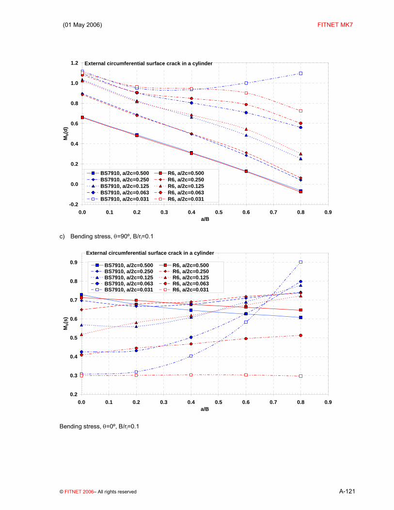
(01 May 2006) FITNET MK7
© FITNET 2006– All rights reserved A-121
External circumferential surface crack in a cylinder
-0.2
0.0
0.2
0.4
0.6
0.8
1.0
1.2
0.0 0.1 0.2 0.3 0.4 0.5 0.6 0.7 0.8 0.9a/B
Mb(
d)
BS7910, a/2c=0.500 R6, a/2c=0.500BS7910, a/2c=0.250 R6, a/2c=0.250BS7910, a/2c=0.125 R6, a/2c=0.125BS7910, a/2c=0.063 R6, a/2c=0.063BS7910, a/2c=0.031 R6, a/2c=0.031
c) Bending stress, θ=90º, B/ri=0.1
External circumferential surface crack in a cylinder
0.2
0.3
0.4
0.5
0.6
0.7
0.8
0.9
0.0 0.1 0.2 0.3 0.4 0.5 0.6 0.7 0.8 0.9a/B
Mb(
s)
BS7910, a/2c=0.500 R6, a/2c=0.500BS7910, a/2c=0.250 R6, a/2c=0.250BS7910, a/2c=0.125 R6, a/2c=0.125BS7910, a/2c=0.063 R6, a/2c=0.063BS7910, a/2c=0.031 R6, a/2c=0.031
Bending stress, θ=0º, B/ri=0.1

FITNET FFS – MK7– Annex A
A-122 © FITNET 2006 – All rights reserved
b) Extended Crack
BS 7910 Solution [A.3] Note that this solution is appropriate for membrane loading only; bending stresses Pb and Qb should be added to Pm and Qm for assessment purposes. The stress intensity factor solution is calculated from equations (A.1 to (A.6 where
M = fw = 1;
( ){ }( )( ) ( )( )
0.52
b 2 2
11 1.080.8 41 1 1 11 1
λ μλ λλ μ λ μλ μ λ
−⎡ ⎤⎧ ⎫−− ⎪ ⎪= + +⎢ ⎥⎨ ⎬
− − − −⎡ ⎤ ⎪ ⎪⎢ ⎥⎩ ⎭⎣ ⎦− − −⎢ ⎥⎣ ⎦
mM M = (A.77)
where:
//
i or ra B
λμ==
Validity limits: None given

(01 May 2006) FITNET MK7
© FITNET 2006– All rights reserved A-123
R6 Solution [A.19] The stress intensity factor KI is given by
( ) ( )π
−=
=
⎛ ⎞= −⎜ ⎟⎝ ⎠
∑∫3
3 2
01
1 / , / 12
iia
I i ii
uK P u f a B B r duaa
(A.78)
The stress distribution P = P(u) is to be taken normal to the prospective crack plane in an uncracked cylinder. The co-ordinate u is the distance from the outer surface of the cylinder as shown above. The geometry functions fi (i = 1 to 3) are given in Table A.24 for the deepest point of the crack.

FITNET FFS – MK7– Annex A
A-124 © FITNET 2006 – All rights reserved
Table A.24 R6 geometry functions for an extended external circumferential crack in a cylinder.
B/ri = 0.43
a/B
0 2.000 1.359 0.2200.1 2.000 1.642 0.236 0.2 2.000 2.127 0.307 0.3 2.000 2.727 0.447 0.4 2.000 3.431 0.668 0.5 2.000 4.271 0.951 0.6 2.000 5.406 1.183
B/ri = 0.25
a/B
0 2.000 1.362 0.2210.1 2.000 1.659 0.221 0.2 2.000 2.220 0.303 0.3 2.000 2.904 0.535 0.4 2.000 3.701 0.857 0.5 2.000 4.603 1.311 0.6 2.000 5.671 1.851
B/ri = 0.11
a/B
0 2.000 1.364 0.2200.1 2.000 1.694 0.211 0.2 2.000 2.375 0.310 0.3 2.000 3.236 0.630 0.4 2.000 4.252 1.136 0.5 2.000 5.334 1.972 0.6 2.000 6.606 2.902
Plot See Figure A.22 for details; this compares the R6, BS 7910 and API solutions. The BS 7910 solution for an extended surface crack in a plate is also shown for information. Note that the BS 7910 solution falls below the solutions given in R6 and API 579, and is also lower than the BS 7910 solution for an extended internal circumferential crack in a cylinder (cf Figure A.20). This is anomalous, and the R6 solution is recommended.

(01 May 2006) FITNET MK7
© FITNET 2006– All rights reserved A-125
Figure A.22 Normalised K-solution for extended external circumferential crack in a cylinder
Extended external circumferential crack in a cylinder
1.0
1.2
1.4
1.6
1.8
2.0
2.2
2.4
2.6
0.0 0.1 0.2 0.3 0.4 0.5 0.6 0.7 0.8a/B
Mm
BS, B/ri=0.11BS, B/ri=0.25R6, B/ri=0.11R6, B/ri=0.25API, B/ri=0.10API, B/ri=0.20Flat plate
a) Membrane stress
Extended external circumferential crack in a cylinder
0.7
0.8
0.9
1.0
1.1
1.2
1.3
1.4
1.5
1.6
1.7
1.8
1.9
2.0
0.0 0.1 0.2 0.3 0.4 0.5 0.6 0.7 0.8a/B
Mb
BS, B/ri=0.11, implied MbBS, B/ri=0.25, implied MbR6, B/ri=0.11R6, B/ri=0.25Flat plate
b) Bending stress

FITNET FFS – MK7– Annex A
A-126 © FITNET 2006 – All rights reserved
A.4.2.3 Embedded crack
a) Finite crack
BS 7910 Solution The flat plate solution in A.2.2.3 can be applied to embedded cracks in shells. M = 1 Validity limits: None given R6 No solution available

(01 May 2006) FITNET MK7
© FITNET 2006– All rights reserved A-127
b) Extended Crack
BS 7910, R6 No solution available API 579 Solution API 579 recommends the use of the flat plate solution (see A.2.3.2).

FITNET FFS – MK7– Annex A
A-128 © FITNET 2006 – All rights reserved
A.5 Cracks In Nozzles BS 7910 solution The flat plate solution in A.2.7 can be applied to radial internal corner cracks in nozzles, together with appropriate stress concentration factors. Validity limits: None given R6 No solution available.

(01 May 2006) FITNET MK7
© FITNET 2006– All rights reserved A-129
A.6 Welded joints A.6.1 Butt, Full Penetration and Attachment Welds with Surface Crack at Weld Toe
BS 7910 Solution BS7910 advises that, when a flaw or crack is situated in a region of local stress concentration such as the weld toe, it is necessary to include the effect of the stress concentration field when calculating KI. Unless the KI solution being used already incorporates the influence of the stress concentration, it is necessary to introduce the correction factor Mk, which is a function of crack size, geometry and loading. In general, the correction factor, Mk, is the product of the ratio of the K for a crack in material with the stress concentration to the K for the same crack in material without the stress concentration. Thus, Mk normally decreases with increases in through-thickness distance z from the weld toe to unity at crack heights of typically 30 % of material thickness. For butt welds, T-butt welds, full penetration cruciform joints and members with fillet or butt-welded attachments, Mk has been found to be a function of z, B and L. Here z is the height, measured from the weld toe, and L is the overall length of the attachment measured from weld toe to weld toe, as shown in the figures above. The Mkm and Mkb stress intensity factor magnification factors, for membrane and bending loading, are required for the general stress intensity factor solutions in equations (A.1 to (A.6. The resulting relationships are given below. Mk has been calculated by 2-D finite element analysis for profiles representing sections of the welded joint geometry. Thus, Mk is directly applicable to the case of a straight-fronted weld toe surface crack (ie a/2c = 0). However, experience indicates that it can also be applied to semi-elliptical cracks (0 ≤ a/2c ≤ 0.5) and other flaw types. The nature of the finite element model used to calculate Mk is such that the solutions produced are not applicable for z = 0, and near-surface Mk values should be used (z = 0.15 mm) for the intersection of surface flaws with the weld toe, and for through-thickness flaws at weld toes.

FITNET FFS – MK7– Annex A
A-130 © FITNET 2006 – All rights reserved
The solutions presented apply for 45º weld profiles (α=45º): Mk is slightly lower for lower angles and vice versa. More accurate solutions based on 3D-stress analysis of semi-elliptical cracks at weld toes are available, and one such solution is presented in Section A.6.1.2. A.6.1.1 Solutions based on 2D FEA [A.41] In general the following solutions apply:
w
k BzvM ⎥⎦⎤
⎢⎣⎡=
(A.79)
down to Mk = 1 where v and w have the values given in Table A.25 for cracks at the toes of full penetration butt or attachment welds.
Table A.25 Values of v and w for axial and bending loading
Loading mode L/B z/B v w Axial ≤ 2 ≤ 0.05(L/B)0.55 0.51(L/B)0.27 −0.31
>0.05(L/B)0.55 0.83 −0.15(L/B)0.46 >2 ≤ 0.073 0.615 −0.31 >0.073 0.83 −0.20
Bending ≤ 1 ≤ 0.03(L/B)0.55 0.45(L/B)0.21 −0.31 >0.03(L/B)0.55 0.68 −0.19(L/B)0.21 >1 ≤ 0.03 0.45 −0.31 >0.03 0.68 −0.19
A.6.1.2 Solutions based on 3D FEA [A.46][A.47][A.48] General Alternative stress intensity magnification factor solutions (Mk) for the deepest and surface points of a semi-elliptical weld-toe crack are given in this section. The solutions were obtained by curve fitting to individual finite element analyses. They include the weld profile angle α as variables, but the following simplified solutions are valid for 45º weld profiles with sharp radii (less than 0.1B) and for the following parametric ranges: 0.005 / 1.00.05 / 2 0.50.5 / 2.75
a Ba c
L B
< <≤ ≤≤ ≤
(for L/B > 2.75, use the value for L/B = 2.75)

(01 May 2006) FITNET MK7
© FITNET 2006– All rights reserved A-131
Deepest point a) Axial
( ) ( ) ( )km 1 2 3= , + + ,a a a a LM f f fB c B B B (A.80)
where:
( ) ( ) ( ){ } ( ){ }31 2 0.050 966
1 4, = 0.433 58 + 0.931 63exp +gg g a Ba af a B a B gB c
⎡ ⎤+ −⎢ ⎥⎣ ⎦
where:
( ) ( )21 = 1.034 3 0.156 57 + 1.340 9g a c a c− − ;
( ) 0 611 532 = 1.321 8 .g a c − ;
( )3 = 0 872 38 + 1 278 8g . a c .− ;
( ) ( ) ( )3 24 = 0.461 90 0.670 90 0.375 71 4.6511g a c a c a c− + − + .
and where:
( ) ( ){ } ( ) ( )176.419 9 0.107 40 /2 = 0.215 21 1 + 2.814 1 a Baf a B a BB
−− − ;
( ) ( )( ) ( ) ( ) ( ){ }5 0.230 03 23 6 7 8, = 0.339 94 + 1.949 3 +ga Lf a B a B g a B g a B gB B + + ;
where:
( ) ( ) ( )3 25 = 0.015 647 + 0.090 889 0.171 80 0.245 87g L B L B L B− − − ;
( ) ( )26 = 0.201 36 + 0.933 11 0.414 96g L B L B− − ;
( ) ( )27 = 0.201 88 0.978 57 + 0.068 225g L B L B− ;
( ) ( )28 = 0.027 338 + 0.125 51 11.218g L B L B− − .
NOTE If equation (A.80 gives a value of Mk < 1.0, assume that Mk = 1.0. b) Bending If 0.005 ≤ a/B ≤ 0.5, then the following expression applies:

FITNET FFS – MK7– Annex A
A-132 © FITNET 2006 – All rights reserved
( ) ( ) ( )kb = , + + ,1 2 3a a a a LM f f fB c B B B (A.81)
where:
( ) ( ) ( ){ } ( ){ }31 2+ 0.103 64
4, = 0.065 916 + 0.520 86exp +1gg g a Ba af a B a B gB c
⎡ ⎤ −⎢ ⎥⎣ ⎦ ;
Where:
( ) ( )21 = 0.014 992 0.021 401 0.238 51g a c a c− − − ;
( ) 1.027 82 = 0.617 75g a c − ;
( )3 = 0.000 132 42 1.474 4g a c − ;
( ) ( ) ( )3 24 = 0.287 83 + 0.587 06 0.371 98 0.898 87g a c a c a c− − −
and where:
( ) ( ) ( ) 52.808 62 = 0.219 950 1 + 0.021 403 gaf a B a BB − − ;
where:
( ) ( )25 = 17.195 + 12.468 0.516 62g a B a B− − ;
and where:
( ) ( )( ) ( ) ( ) ( ){ }6 0.200 77 23 7 8 9, = 0.233 44 / 0.148 27 + / /ga Lf a B a/B g a B g a B gB B
−− + + ;
where
( ) ( ) ( )3 26 0.059 798 0.380 91 0.802 20 0.319 06g L B L B L B= − + − + ;
( ) ( )27 = 0.358 48 + 1.397 5 1.753 5g L B L B− − ;
( ) ( )28 = 0.312 88 1.359 9 + 1.6611g L B L B− ;

(01 May 2006) FITNET MK7
© FITNET 2006– All rights reserved A-133
( ) ( )29 = 0.001 470 1 0.002 507 4 0.008 984 6g L B L B− − − .
NOTE If equation (A.81 gives a value of Mk < 1.0, assume that Mk = 1.0. Surface point a) Axial
( ) ( ) ( )km = , , , , ,1 2 3a c a a a aL LM f f fB a B T c B c B× × (A.82)
where:
( ) ( ) ( ){ }22
6 7 82 3 4 + ++ +1 1 5, , = + 1
c cc c g g gg g g a aa aa c Lf g a B g a BB a B
⎧ ⎫⎧ ⎫ ⎪ ⎪⎛ ⎞ ⎛ ⎞⎪ ⎪⎛ ⎞ ⎛ ⎞⎨ ⎬⎨ ⎬ ⎜ ⎟ ⎜ ⎟⎜ ⎟ ⎜ ⎟ ⎝ ⎠ ⎝ ⎠⎝ ⎠ ⎝ ⎠ ⎪ ⎪⎪ ⎪ ⎩ ⎭⎩ ⎭ −
where:
( ) ( )21 = 0.007 815 7 0.070 664 + 1.850 8g c a c a− ;
( ) ( )22 = 0.000 054 546 + 0.000 136 51 0.000 478 44g L B L B− − ;
( ) ( )23 = 0.000 491 92 0.001 359 5 + 0.011 400g L B L B− ;
( ) ( )24 = 0.007 165 4 0.033 399 0.250 64g L B L B− − ;
( ) ( )25 = 0.018 640 + 0.243 11 1.764 4g c a c a− − ;
( ) ( )26 = 0.00 167 13 + 0.009 062 0 0.016 479g L B L B− − ;
( ) ( )27 = 0.003 161 5 0.010 944 + 0.139 67g L B L B− − ;
( ) ( ) ( )3 28 = 0.045 206 + 0.323 80 0.689 35 + 1.495 4g L B L B L B− − .
and where:
( ) ( ) ( ){ }( ) ( ){ } 10922 , = 0.286 39 + 0.354 11 + 1.643 0 + 0.274 49 1 gga af a c a c a B a BB c − − ;
where:
( ) ( )29 = 0.254 73 + 0.409 28 + 0.002 189 2g a c a c− ;

FITNET FFS – MK7– Annex A
A-134 © FITNET 2006 – All rights reserved
( ) ( )210 = 37.423 15.741 +64.903g a c a c− .
and where:
( ) ( ) ( ){ }130.754 293 11 12, , exp ga a Lf g a B g a BB c B = + ;
where:
( ) ( ) ( )3 211 0.105 53 0.598 94 1.094 2 1.265 0g L B L B L B= − + − − ;
( ) ( ) ( )3 212 0.043 891 0.248 98 0.447 32 0.601 36g L B L B L B= − + + ;
( ) ( )213 0.011 411 0.004 369 0.517 32g a c a c= − + + .
b) Bending
( ) ( ) ( )kb = , , , , ,1 2 3a c a a a aL LM f f fB a B B c B c B× × (A.83)
where:
( ) ( ) ( ){ }22
6 7 82 3 4 + ++ +1 1 5 9, , = + 1
c cc c g g gg g g a aa aa c Lf g a B g a B gB a B
⎧ ⎫⎧ ⎫ ⎪ ⎪⎛ ⎞ ⎛ ⎞⎪ ⎪⎛ ⎞ ⎛ ⎞⎨ ⎬⎨ ⎬ ⎜ ⎟ ⎜ ⎟⎜ ⎟ ⎜ ⎟ ⎝ ⎠ ⎝ ⎠⎝ ⎠ ⎝ ⎠ ⎪ ⎪⎪ ⎪ ⎩ ⎭⎩ ⎭ − + ;
where:
( ) ( )21 = 0.002 323 2 0.000 371 56 + 4.598 5g c a c a− ;
( ) ( )22 = 0.000 044 010 + 0.000 144 25 0.000 867 06g L B L B− − ;
( ) ( )23 = 0.000 399 51 0.001 371 5 + 0.014 251g L B L B− ;
( ) ( )24 = 0.004 616 9 0.017 917 0.163 35g L B L B− − ;
( ) ( )25 = 0.018 524 + 0.278 10 5.425 3g c a c a− − ;
( ) ( )26 = 0.000 379 81 + 0.002 507 8 + 0.000 146 93g L B L B− ;
( ) ( )27 = 0.003 850 8 0.002 321 2 0.026 862g L B L B− + − ;
( ) ( ) ( )3 28 = 0.011 911 + 0.082 625 0.160 86 + 1.230 2g L B L B L B− − ;
( ) ( ) ( )3 29 = 0.277 98 1.214 4 2.468 0 + 0.099 981g a B a B a B− − .

(01 May 2006) FITNET MK7
© FITNET 2006– All rights reserved A-135
and where:
( ) ( ) ( ){ }( ) ( ){ } 111022 , = 0.350 06 + 0.407 68 + 1.705 3 + 0.249 88 1 gga af a c a c a B a BB c − −
where:
( ) ( )210 = 0.259 22 + 0.395 66 + 0.011 759g a c a c− ;
( ) ( )211 = 6.597 4 + 55.787 + 37.053g a c a c .
and where:
( ) ( ) ( ){ }140.947 613 12 13, , / exp / ga a Lf g a B g a BB c B = + ;
where:
( ) ( ) ( )3 212 0.148 95 0.815 26 1.479 5 0.898 08g L B L B L B= − + − − ;
( ) ( ) ( )3 213 0.055 459 0.301 80 0.541 54 0.534 33g L B L B L B= − + + ;
( ) ( )214 0.013 43 0.006 670 2 0.759 39g a c a c= − + + .
Validity limits: valid for 45º weld profiles with sharp radii (less than 0.1B) and for the following parametric ranges: 0.005 < a/B ≤ 1.0 0.05 < a/2c < 0.5 0.5 ≤ L/B ≤ 2.75 (for L/B > 2.75, use the value for L/B = 2.75) R6 No solution available.

FITNET FFS – MK7– Annex A
A-136 © FITNET 2006 – All rights reserved
A.6.2 Load Carrying Fillet or Partial Penetration Weld with Surface Crack at Weld Toe [A.49]
BS 7910 Solution For cracks at the toes of fillet or partial penetration load-carrying welds, the 2-D approach described in Section A.6.1.1 may be used, where the values of v and w are those corresponding to L/B >2 for axial loading or L/B ≥ 1 for bending. The resulting value of v is then multiplied by (B/tw)0.5. R6 No solution available

(01 May 2006) FITNET MK7
© FITNET 2006– All rights reserved A-137
A.6.3 Root Cracks in Cruciform Joints
BS 7910 Solution [A.49] Note that this refers only to straight fronted cracks [a/2c = 0 ]. The stress intensity solution is calculated from equations (A.1 to (A.6 where: M = Mm = Mb = 1; σ is the stress in the loaded member. The influence of joint geometry on stress intensity factors for root cracks in fillet and partial penetration welds is accounted for by the application of modified finite width correction and stress intensity factor magnification factors, fwm, fwb, Mkm and Mkb, for membrane and bending loading. Membrane loading
0.5secwm
2a = f2 Wπ⎛ ⎞⎡ ⎤⎛ ⎞
⎜ ⎟⎜ ⎟⎢ ⎥⎝ ⎠⎣ ⎦⎝ ⎠
(A.84)
( ) ( )2km o 1 22 / 2 / = + a W + a WM λ λ λ (A.85)
where:

FITNET FFS – MK7– Annex A
A-138 © FITNET 2006 – All rights reserved
( )( ) ( ) ( ) ( )
( ) ( ) ( ) ( )
0
2 3 41
2 3 42
0.956 0.343 /
1.219 6.210 / 12.220 / 9.704 / 2.741 /
1.954 7.938 / 13.299 / 9.541 / 2.513 /
h B
h B h B h B h B
h B h B h B h B
λ
λ
λ
= −
= − + − + −
= − + − +
Range of application: 0.1 2 / 0.7;0.2 / 1.2.
a Wh B
≤ ≤≤ ≤
Bending loading
( )0.52 3 4
wb 31 1 3 11 = 1 + + + 0.464
2 2 8 161aa a a a afa
− ⎡ ⎤−⎢ ⎥⎣ ⎦− (A.86)
where:
2 /a Wα =
( )( ) ( ) ( )1 2 ln 2 /kb 0exp 2 / 2 / a W= a W a WM λ λλ (A.87)
for 0.2 ≤ h/B ≤ 0.7
( )( ) 1kb 0exp 2 /= a WM μμ
for 0.7 ≤ h/B ≤ h/B ≤ 0.7 where:
λ 0 = 0.792 - 3.560(h/B) + 1.276(h/B)2
λ 1 = 1.064 - 4.898(h/B) + 3.670(h/B)2
λ 2 = 0.496 - 1.328(h/B) + 1.012(h/B)2
μ 0 = 0.285(h/B)2 – 1.866(h/B)
μ 1 = 0.028(h/B) – 0.761
Range of application: 0.1 ≤ 2a/W ≤ 0.7. R6 No solution available

(01 May 2006) FITNET MK7
© FITNET 2006– All rights reserved A-139
A.7 Round Bars and Bolts
A.7.1 Straight-fronted Crack in a Bar
BS 7910 Solution [A.50]
The stress intensity factor is calculated from equations (A.1 to (A.6: Where: M = Mkm = Mkb = fw = 1, with Mm and Mb as follows:
2 3 4m
1 10.926 1.771 26.421 78.481 87.9112 2 2 2a a = +M r r r r
⎛ ⎞ ⎛ ⎞ ⎛ ⎞ ⎛ ⎞− − −⎜ ⎟ ⎜ ⎟ ⎜ ⎟ ⎜ ⎟⎝ ⎠ ⎝ ⎠ ⎝ ⎠ ⎝ ⎠
(A.88)
2 3 4
b = 1.04 3.64 16.86 32.59 28.412 2 2 2a a a a + + M r r r r
⎛ ⎞ ⎛ ⎞ ⎛ ⎞ ⎛ ⎞− −⎜ ⎟ ⎜ ⎟ ⎜ ⎟ ⎜ ⎟⎝ ⎠ ⎝ ⎠ ⎝ ⎠ ⎝ ⎠
(A.89)
Validity limits: Range of application: 0.062 5 ≤ a/2r ≤ 0.625. R6 No solution available.

FITNET FFS – MK7– Annex A
A-140 © FITNET 2006 – All rights reserved
A.7.2 Semi-circular Surface Crack in a Bar
BS 7910 Solution [A.50]
The stress intensity factor solution is calculated from equations (A.1 to (A.6 Where: M = Mkm = Mkb = fw = 1, with Mm and Mb as follows:
m sin3
0.752 2.02 0.37 12 4a aM gr r
π⎡ ⎤⎧ ⎫⎛ ⎞ ⎛ ⎞⎢ ⎥= + + −⎨ ⎬⎜ ⎟ ⎜ ⎟⎢ ⎥⎝ ⎠ ⎝ ⎠⎩ ⎭⎣ ⎦ (A.90)
b sin4
0.923 0.199 14aM gr
π⎡ ⎤⎧ ⎫⎛ ⎞⎢ ⎥= + −⎨ ⎬⎜ ⎟⎢ ⎥⎝ ⎠⎩ ⎭⎣ ⎦ (A.91)
where:
tan
cos
0.51.844 4=
4
a a r rg
ar
π ππ
π
⎧ ⎫⎛ ⎞ ⎛ ⎞⎨ ⎬⎜ ⎟ ⎜ ⎟
⎝ ⎠ ⎝ ⎠⎩ ⎭⎛ ⎞⎜ ⎟⎝ ⎠
NOTE K solutions for straight fronted cracks in round bars (Section A.7.1) are generally conservative compared to semi-circular surface cracks. Validity limits: Range of application: a/2r <0.6. R6 No solution available.

(01 May 2006) FITNET MK7
© FITNET 2006– All rights reserved A-141
A.7.3 Fully Circumferential Crack in a Bar
BS 7910 Solution [A.2] The stress intensity factor solution is calculated from equations (A.1 to (A.6 Where: M = Mkm = Mkb = fw = 1, with Mm and Mb as follows:
( )
2 3 41.5m 1.5 1 0.5 0.375 0.363 0.731
2r a r a r a r ar= + + +M r r r rr a
⎧ ⎫− − − −⎪ ⎪⎛ ⎞ ⎛ ⎞ ⎛ ⎞ ⎛ ⎞−⎨ ⎬⎜ ⎟ ⎜ ⎟ ⎜ ⎟ ⎜ ⎟⎝ ⎠ ⎝ ⎠ ⎝ ⎠ ⎝ ⎠− ⎪ ⎪⎩ ⎭
(A.92)
( )b
2 3 4 52.5
2.50.375 1 0.5 0.375 0.313 0.273 0.537r r a r a r a r a r aM
r r r r rr a
⎧ ⎫− − − − −⎪ ⎪⎛ ⎞ ⎛ ⎞ ⎛ ⎞ ⎛ ⎞ ⎛ ⎞= + + − + +⎨ ⎬⎜ ⎟ ⎜ ⎟ ⎜ ⎟ ⎜ ⎟ ⎜ ⎟⎝ ⎠ ⎝ ⎠ ⎝ ⎠ ⎝ ⎠ ⎝ ⎠− ⎪ ⎪⎩ ⎭
(A.93)
Validity limits: None given R6 No solution available

FITNET FFS – MK7– Annex A
A-142 © FITNET 2006 – All rights reserved
A.7.4 Semi-circular Crack in a Bolt
BS 7910 Solution [A.50]
This solution has been developed for the ISO M8 × 1.0 bolt geometry. The stress intensity factor is calculated from equations (A.1 to (A.6 Where: M = Mkm = Mkb = fw = 1, with Mm and Mb as follows:
( ) ( )2m b 0 1 2/ 2 / 2M = M = + a r + a rλ λ λ (A.94)
where the following apply for the conditions indicated: a) Tension loading (Mm), at the deepest point in the crack:
λ 0 = 1.015 5 - 0.237 5(a/c);
λ 1 = -0.584 + 0.015(a/c);
λ 2 = 6.455 75 - 3.348 75(a/c).
Intersection of the crack with the free surface:
λ 0 = 0.469 5 + 0.822 5(a/c);
λ 1 = 0.377 75 - 1.478 75(a/c);
λ 2 = -0.160 25 + 2.946 25(a/c).

(01 May 2006) FITNET MK7
© FITNET 2006– All rights reserved A-143
b) Bending loading (Mb), at the deepest point in the crack:
λ 0 = 0.893 75 - 0.363 75(a/c);
λ 1 = -0.559 25 + 0.366 25(a/c);
λ 2 = 2.379 - 1.88(a/c).
Intersection of the crack with the free surface:
λ 0 = 0.653 5 - 0.092(a/c);
λ 1 = -1.148 75 + 1.558 75(a/c);
λ 2 = 3.028 - 1.855(a/c).
Validity limits: 0.2 ≤ a/c ≤ 1; 0.1 ≤ a/2r ≤ 0.5. R6 No solution available.

FITNET FFS – MK7– Annex A
A-144 © FITNET 2006 – All rights reserved
A.7.5 Embedded Crack in a Bar
BS 7910, R6, API 579, SINTAP No solution available. FKM solution [A.51] A solution for this geometry is given in the FKM procedure. The bar may be under tension (P denotes the tensile load), bending (M denotes bending moment) and torsion (T) as follows:
( )
( )
( )π
π
−⎡ ⎤
= +⎢ ⎥+ −⎢ ⎥⎣ ⎦
2 2 2 2
4 .I p M
r aMa rK F P F a
r a r a (A.95)
where:
λ λ λπ⎡ ⎤= + − +⎢ ⎥⎣ ⎦
2 22 1 51 0.2682 8pF
λ = ar
λ λ λ λ λπ⎡ ⎤= + + + − +⎢ ⎥⎣ ⎦
2 3 4 54 1 3 5 931 0.4833 2 8 16 128MF
( )
( )π
π
−
=−4 4
2III T
r aTa
rK F ar a
(A.96)
where:
λ λ λ λ λπ⎡ ⎤= + + + − +⎢ ⎥⎣ ⎦
2 3 4 54 1 3 5 931 0.0383 2 8 16 128rF

(01 May 2006) FITNET MK7
© FITNET 2006– All rights reserved A-145
A.8 Tubular Joints BS 7910 Solution BS 7910 does not provide any specific SIF solutions. It cites papers [A.51][A.53][A.54][A.55] where SIFs were obtained using numerical methods. R6, API 579 No solution available. SINTAP [A.54] [Ree et al] Section AIII.5 of SINTAP covers the following geometries and loading modes: • Surface crack at the saddle point of T-joints
• axial loading: deepest and surface points • in-plane bending: deepest and surface points • out-of-plane bending: deepest and surface points
• Surface crack at the saddle point of Y-joints,
• axial loading: deepest point
FITNET FFS – MK7– Annex A
A-146 © FITNET 2006 – All rights reserved
A.9 Bibliography
[A.1] Murakami Y: ‘Stress intensity factors handbook’, Pergamon Press, Oxford, 1987, pp.1356-1358.
[A.2] Tada H, Paris P C and Irwin G: ‘The stress analysis of cracks handbook’, Third Edition, ASME, New York, 2000.
[A.3] Rooke D P and Cartwright D J: ‘Compendium of stress intensity factors’, HM Stationery Office, London, 1976.
[A.4] Sih G C, Paris P C and Erdogan F: ‘Stress intensity factors for plane extension and plate bending problems’, J Appl Mech 29, 1962, pp 306-312.
[A.5] BS 7910, 'Guide on methods for assessing the acceptability of flaws in metallic structures', BSI, 2005.
[A.6] R6: ‘Assessment of the integrity of structures containing defects’, Rev 4, British Energy, 2001.
[A.7] API Recommended Practice 579, Fitness-for-Service, API Publishing Services, First edition January 2000.
[A.8] SINTAP (Structural Integrity Procedures for European Industry), Final Procedure, November 1999.
[A.9] FKM, ‘Bruchmechanischer Festigkeitsnachweis’, 2004, also available in English as ‘Fracture mechanics proof of strength for engineering components’, 2004.
[A.10] INSTA Technical Report, 1991: 'Assessment of structures containing discontinuities', Materials Standards Institution, Stockholm.
[A.11] RSE-M: Feb 2000: Regles de surveillance en exploitation des materials mecaniques des ilots nucleaires R.E.P.
[A.12] IIW: ‘IIW guidance on assessment of the fitness for purpose of welded structures’, Draft for Development, 1990, IIW/IIS-SST-1157-90
[A.13] Smith, M C: ‘A comparison of R6 Code SIF solutions for defects in cylinder with other solutions’, British Energy Generation Report E/REP/ATEC/0006/GEN/01, 2001.
[A.14] Fett T and Munz D: ‘Stress intensity factors and weight functions’, Computational Mechanics Publications, Southampton, 1997.
[A.15] Newman J C and Raju I S (1984): ‘Stress intensity factor equation for cracks in three-dimensional finite bodies subjected to tension and bending loads’, Report NASA-TM-85793, National Aeronautics and Space Administration, Langley Research Centre, Hampton, VA. 1984.
[A.16] Sih G C: ‘Mechanics of Fracture 3, Plates and shells with cracks’, Noordhoff International Publishing Leiden, The Netherlands, 1977.
[A.17] Raju I S and Newman JC (1979): ‘Stress intensity factors for a wide range of semi-elliptical surface cracks in finite thickness plates’, Engineering Fracture Mechanics, 11 (4) pp 817-829. ISSN 0013-7944. 1979.
[A.18] T Fett, D Munz and J Neumann, Local stress intensity factors for surface cracks in plates under power-shaped stress distributions, Engng Fract Mech 36, 647-651 (1990).
[A.19] Wu X R and Carlsson A J: ‘Weight functions and stress intensity factor solutions’, Pergamon Press, Oxford, 1991.
[A.20] Zvezdin Y I: ‘Handbook - Stress intensity and reduction factors calculation’, Central Research Institute for Technology of Machinery Report MR 125-01-90, Moscow, 1990.

(01 May 2006) FITNET MK7
© FITNET 2006– All rights reserved A-147
[A.21] Fuhrey M and Osage D A: ‘Stress intensity factor solutions for long surface cracks in flat plates, cylinders and spheres’. To be published.
[A.22] Merkblatt DVS 2401: ‘Bruchmechanische Bewertung von Fehlern in Schweissverbindungen’, Deutscher Verband fűr Schweisstechnik, 1982.
[A.23] Chell G C: ‘The stress intensity factors and crack profiles for centre and edge cracks in plates subject to arbitrary stresses’, Int J Fracture, 12, 1976, pp33-46.
[A.24] Newman J C and Raju I S (1983): ‘Stress intensity factor equation for cracks in three-dimensional finite bodies’, ASTM STP 791, 1983, ppI238 – I265.
[A.25] Zahoor A: ‘Closed form expressions for fracture mechanics analysis of cracked pipes’, J Pressure Vessel Technology, 107, N2, 1985, pp203-205.
[A.26] Chell G C: ‘ADISC: A computer program for assessing defects in spheres and cylinders’, CEGB Report TPRD/L/MT0237/M84, 1984.
[A.27] Delale F and Ergodan F: ‘Effect of transverse shear and material orthotropy in a cracked spherical cap’, Int J Solids Structures, 15, 1979, pp907-926.
[A.28] France C C, Green D, Sharples J K and Chivers T C: ‘New stress intensity factors and crack opening area solutions for through-wall cracks in pipes and cylinders’, ASME PVP Conference Fatigue and Fracture 1997, PVP-Vol. 350, pp. 143-193.
[A.29] Newman J C and Raju I S (1981): ‘An empirical stress intensity factor equation for the surface crack’, Engineering Fracture Mechanics, 15, 1981, pp185-192.
[A.30] Raju I S and Newman J C (1982): ‘Stress intensity factor influence coefficients for internal and external surface crack in cylindrical vessels’, In: Palusamy S S and Sampath S G, eds., ‘Aspects of fracture mechanics in pressure vessels and piping’. Presented at pressure vessels and piping conference, Orlando, FL, 27 June – 2 July, 1982. New York: ASME. ASME PVP Vol.-95, 35-48.
[A.31] Raju I S and Newman J C (1978): ‘Stress intensity factor influence coefficients for internal and external surface cracks in cylindrical vessels, ASME PVP, 58, 1978, pp37-48.
[A.32] Joseph P F and Erdogan F: ‘Surface crack problem in plates’, Int J Fracture, 41 (2), 1989, pp.105-131.
[A.33] Andrasic C P and Parker A P: ‘Dimensionless stress intensity factors for cracked thick cylinders under polynomial crack face loadings’, Engineering Fracture Mechanics, 19 (1), 1984, pp.187-193.
[A.34] Al Laham S: ‘Stress intensity factor and limit load handbook’, British Energy Generation Report EPD/GEN/REP/0316/98, Issue 2, 1999.
[A.35] D Green and J Knowles, The treatment of residual stress in fracture assessment of pressure vessels, ASME J Pres Ves Tech, 116, 345-352 (1994).
[A.36] Dedhia D D and Harris D O: ‘Improved influence functions for part-circumferential cracks in pipes’, In: G.M. Wilkowsky, ed. Circumferential cracks in pressure vessels and piping. Presented at the 4th National Congress on Pressure Vessel and Piping Technology, Portland, Oregon, 19-24 June 1983, Vol.2, ASME PVP Vol. 95, New-York, 1984, pp35-48.
[A.37] Bergman M and Brickstad B: ‘Stress-intensity factors for circumferential cracks in pipes by line-spring calculations’, Swedish Plant Inspectorate, SA/FoU Report 90/05, Stockholm, 1990.
[A.38] M. Bergman, Stress intensity factors for circumferential surface cracks in pipes, Fatigue Fract Engng Mater Struct 18, 1155-1172 (1995).

FITNET FFS – MK7– Annex A
A-148 © FITNET 2006 – All rights reserved
[A.39] Toribio J: ‘Effect of crack shape and loading conditions on the stress intensity factor for a cracked bolt’, In: Barbas et al., eds. Proc. 11th international conference on offshore mechanics and arctic engineering, (OMAE’92), Calgary, Canada 7-12 June 1992, Vol. III-B, Materials Engineering, New York, ASME, 1992, pp363-370.
[A.40] Chapuliot S: ‘Formulaire de K1 pour les tubes comportant un defaut de surface semi-elliptique longitudinal, ou circomferentiel, interne ou externe’, CEA-R-5900, CEA Saclay, Gif-sur-Yvette, France, March 2000.
[A.41] Maddox S J. and Andrews R M, 1990: ‘Stress intensity factors for weld toe cracks’. In: M.H. ALIABADI, C.A. BREBBIA and D.J. CARTWRIGHT, eds., Localized damage computer-aided assessment and control. Proc. 1st international conference on computer-aided assessment and control of localized damage, Portsmouth, UK, 26-28 June 1990. Vol.2. Southampton: Computational Mechanics Pubs. 329-342. ISBN 1853120685.
[A.42] Kiefner J F, Maxey W A, Eiber R J and Duffy A R: ‘Failure stress levels of flaws in pressurized cylinders’, Proc Conf, Philadelphia, 28-30 Aug 1972, ASTM STP 536, pp461-481.
[A.43] Willoughby A A and Davey T G: ‘Plastic collapse at part wall flaws in plates’, In: R.P. WEI, ed. Fracture mechanics: perspectives and directions. Proc. 20th national symposium, Bethlehem, PA, 23-25 June 1981, ASTM STP 1020, pp390-409.
[A.44] France C C, Green D and Sharples J K: ‘New stress intensity factor and crack opening area solutions for through wall cracks in pipes and cylinders’, AEAT-0643, 1996.
[A.45] Zang W: ‘Stress intensity factor solutions for axial and circumferential through-wall cracks in cylinders’, SAQ Report SINTAP/SAQ/02, 1997.
[A.46] Bowness D and M M M Lee: ‘Prediction of weld toe magnification factors for semi-elliptical cracks in T-butt joints’, Int J of Fatigue, 22 (5), 2000, pp. 389-396.
[A.47] Thurlbeck S D: ‘A fracture mechanics based methodology for the assessment of weld toe cracks in tubular offshore joints’, PhD Thesis, Department of Civil and Construction Engineering, University of Manchester Institute of Science and Technology, UK, 1991.
[A.48] Cheaitani M J, Thurlbeck S D and Burdekin F M: ‘Fatigue, fracture and plastic collapse of offshore tubular joints using BSI PD 6493:1991. In: Salama et al, Eds. Proc 14th International Conference on Offshore Mechanics and Arctic Engineering, (OMAE 1995), Copenhagen, Denmark 18-22 June 1995, Vol. 3, New York, ASME, 1995, pp41-54.
[A.49] Noblett J E and Andrews R A: ‘A stress intensity factor solution for root defects in fillet and partial penetration welds’, TWI Research Report 575/1996, TWI, Abington, Cambridge, UK, 1996.
[A.50] James L A and Mills W J: ‘Review and synthesis of stress intensity factor solutions applicable to cracks in bolts’, Engineering Fracture Mechanics, 30 (5), 1988, pp641-653.
[A.51] Bentham J B and Koiter W T: ‘Mechanics of fracture 1. Method of analysis and solutions of crack problems’, Ed Sih G C, Noordhoff International Publishing, Leyden, 1973, pp131-178.
[A.52] Haswell J V: ‘A general fracture mechanics model for a cracked tubular joint derived from the results of a finite element parametric study’, Proc 11th Int Conf Conf Offshore Mechanics and Arctic Engineering Conference (OMAE ‘92), Calgary 7-12th June 1992, Vol III-B, ASME, New York, 1992, pp267-274.
[A.53] Ree H C, Han S and Gibson G S: ‘Reliability of solution method and empirical formulas of stress intensity factors for weld toe cracks of tubular joints’, Proc 10th Int Conf Offshore Mechanics and Arctic Engineering Conference (OMAE ‘91), Vol III-B, ASME, New York, 1991, pp441-452.
(01 May 2006) FITNET MK7
© FITNET 2006– All rights reserved A-149
[A.54] Ho C M and Zwerneman F J: ‘Assessment of simplified methods’, Joint Industry Project Fracture Mechanics Investigation of Tubular Joints – Phase Two, Oklahoma State University, Stillwater, OK, Jan 1995.
[A.55] Burdekin F M and Cowling M J: ‘Defect assessment in offshore structures, a procedure, CMPT Publications, Aberdeen, 1998.
[A.56] R-Code: ‘Software for assessing the integrity of structures containing defects’, Version 4.1, British Energy Generation Ltd, 2001.