annual review - steelconstruction.info · 2 nsc annual review in this issue cover image aldgate...
TRANSCRIPT
www.newsteelconstruction.com
Annual Review

2 NSCAnnual Review
In this issue
Cover ImageAldgate Tower, LondonMain client: Aldgate DevelopmentsArchitect: Wilkinson Eyre ArchitectsMain contractor: Brookfield MultiplexProject manager: FtsquaredStructural engineer: ArupSteelwork contractor: SeverfieldSteel tonnage: 5,600tProject Value: £78M
Annual Review
These and other steelwork articles can be downloaded from the New Steel Construction Website at www.newsteelconstruction.com
3 Introduction from BCSA Director General Sarah McCann-Bartlett
4 News A four page review of steel construction news highlights from 2014
8 SSDA Awards The annual steel construction industry awards are a highlight for the sector
10 Commercial A steel solution proved to be the best option for the construction of Aldgate Tower on the City fringes
12 Energy The Great Island power station is now providing electricity for more than 200,000 homes in Ireland
14 Distribution A fourth parcel hub for one of the UK’s largest delivery firms is being built at Hinckley
16 Education The University of the Highlands and Islands is spearheading the regeneration of Inverness
18 The Right Choice Steel provides a host of benefits for designers, contractors, developers and building users
20 Healthcare Steel framed atria and a new façade have been added to the East Wing tower at London’s St Thomas’ Hospital
22 Transport Major improvements are taking place at London Bridge station with steelwork playing a crucial role
24 Commercial Two eight-storey commercial buildings will revitalise the renowned St James’s area of London
26 Residential Nine steel framed accommodation blocks are being constructed for the University of Salford
28 Embodied Carbon Ambitious targets have been set to reduce greenhouse gas emissions and this means a significant improvement in new and existing building performance is required
30 Cost A new guidance document and regularly updated cost analyses make the cost planning process straightforward
32 Thermal Mass Utilising thermal mass advantages of steel frames can reduce emissions and deliver cost savings
33 Website A host of updates and improvements have been added to the steel construction’s go-to website in the last 12 months
34 CE Marking The BCSA’s Dr David Moore explains the concept of Execution Class
3NSCAnnual Review
Introduction
EDITORNick Barrett Tel: 01323 422483 [email protected] EDITORMartin Cooper Tel: 01892 [email protected] EDITORTy Byrd Tel: 01892 [email protected] EDITORAndrew Pilcher Tel: 01892 553147 [email protected] ASSISTANTAlastair Lloyd Tel: 01892 553145 [email protected] REPORTERMike WalterCOMMERCIAL MANAGERFawad Minhas Tel: 01892 [email protected]
PUBLISHED BY BCSA AND TATA STEEL, IN ASSOCIATION WITH SCI
The British Constructional Steelwork Association Ltd4 Whitehall Court, Westminster, London SW1A 2ESTelephone 020 7839 8566 Fax 020 7976 1634Website www.steelconstruction.orgEmail [email protected]
Tata Steel PO Box 1, Brigg Road, Scunthorpe, North Lincolnshire DN16 1BPTelephone 01724 405060Website www.tatasteelconstruction.comEmail [email protected]
The Steel Construction InstituteSilwood Park, Ascot, Berkshire SL5 7QNTelephone 01344 636525 Fax 01344 636570Website www.steel-sci.comEmail [email protected]
CONTRACT PUBLISHER & ADVERTISING SALESBarrett, Byrd Associates7 Linden Close, Tunbridge Wells, Kent TN4 8HHTelephone 01892 524455Website www.barrett-byrd.com
Steel framed buildings cost less to build and can be built considerably faster and more safely than those with alternative framing materials. This NSC Annual Review brings together a number of projects from 2014 that highlight the benefits of using structural steelwork for construction projects. These case studies are real proof of the cost, programme, safety and performance benefits of using steel framing. Each article tells a different story from the BREEAM ‘Excellent’ commercial building achieved at Aldgate to the speedy delivery of student accommodation at the University of Salford. While they may be very different projects, in all cases the use of steel framing has delivered a suite of benefits to the design team, the construction programme, the building owners and its users. This publication also showcases the wider benefits of steel under a number of
headings – such as safety, speed of construction, cost, quality sustainability, innovation, offsite manufacture, and key performance attributes such as vibration and acoustics. Further case studies are available every month in NSC and on the www.steelconstruction.info website. By signing up to NSC and the website at www.newsteelconstruction.com/wp/subscribe-manage-subscription/ you will also receive alerts about updates to design guidance, changes to technical and regulatory issues such as BIM and CE Marking and access to design tools and guidance publications. 2014 was a successful year for steelconstruction with many high pointsas this Review shows. 2015 is already shaping up to be an even more successful year and NSC and www.steelconstruction.info look forward to bringing you news of the very best in UK steel construction.
EDITORIAL ADVISORY BOARDMs S McCann-Bartlett (Chair); Mr N Barrett; Mr D G Brown, SCI; Mr M Crosby; Mr C Dolling, BCSA; Mr R Gordon; Mr A Palmer, Buro Happold; Mr A Palmer, Buro Happold;Mr G H Taylor, Caunton Engineering; Mr M Thompson, Mott MacDonald; Mr O Tyler, Wilkinson Eyre Architects
The role of the Editorial Advisory Board is to advise on the overall style and content of the magazine.
New Steel Construction welcomes contributions on any suitable topics relating to steel construction. Publication is at the discretion of the Editor. Views expressed in this publication are not necessarily those of the BCSA, SCI, Tata Steel or the Contract Publisher. Although care has been taken to ensure that all information contained herein is accurate with relation to either matters of fact or accepted practice at the time of publication, the BCSA, SCI, Tata Steel and the Editor assume no responsibility for any errors or misinterpretations of such information or any loss or damage arising from or related to its use. No part of this publication may be reproduced in any form without the permission of the publishers.
All rights reserved ©2015. ISSN 0968-0098
Steel highlights the best of constructionIntroduction by Sarah McCann-Bartlett, Director General of the British Constructional Steelwork Association.

4 NSCAnnual Review
News
Westfield development boosts regeneration of BradfordHaving stalled for a number of
years, Westfield’s £275M Broadway
development in Bradford has reached
an important milestone with the
completion of the 6,800t steel frame.
Located in the heart of the city
centre, the development will boost the
wider regeneration of Bradford and
provide 2,500 new jobs.
On completion it will total
52,900m² of retail and leisure space
anchored by Debenhams and
Marks & Spencer (M&S) stores, with
1,300 car parking spaces located on
the upper levels.
The large braced steel frame is
Research confirms steel has less on site environmental impact A study comparing the on site impacts of
steel and concrete structures for the same
inner city multi-storey commercial project
has confirmed steel construction has a
lower environmental impact than in situ
concrete systems.
Carried out on behalf of the British
Constructional Steelwork Association,
the Steel Construction Institute (SCI)
compared the on site impacts of a
composite steel cellular beam structure
against a post-tensioned concrete solution.
The weight of materials used to
construct the concrete superstructure was
found to be 282% greater than materials
required for the steel building. This
confirmed that steel is more effective in
terms of resource efficiency and from an
end-of-life waste perspective.
The steel solution had a lower
embodied carbon impact than the concrete
option, while other sustainable benefits
of steel construction included a reduced
number of deliveries to site, less waste
generation and less transport of waste, and
a requirement for less on site labour.
Dr Graham Couchman, CEO of the SCI
said: “The steel sector advocates a whole
life cradle to cradle approach to quantify
the environmental impacts of buildings.
Although the sector has good data on steel
production, much less was known about
the on site construction impacts of steel
based construction systems.
“As an essentially prefabricated
system, steel construction may be expected
to have a lower on site environmental
impact than equivalent in situ concrete
systems and the results of this study bear
this out.”
Steel tackles phased rugby stadium build The Ravenhill Rugby Ground in
Belfast, has been redeveloped with the
construction of three new stands, raising
its capacity from 11,400 to 18,000.
Owned by the Irish Rugby Football
Union, the stadium is the home of Ulster
Rugby who were able to continually
use the ground throughout a phased
construction and demolition programme.
Working on behalf of main contractor
Gilbert-Ash, Ballykine Structural
Engineers erected 800t of steelwork for
the Memorial and Aquinas Stands, as well
as the new Main Stand.
No machinery was allowed to
encroach onto the pitch during the
construction, so cranes and MEWPs had
to be positioned to the rear of each of
the stands.
“This presented a major problem on
the Aquinas Stand, as there was no access
to the rear due to an adjacent school,”
said Ian Kerr, Ballykine Managing
Director.
“We had to offload the 21m long steel
rafters outside and bring them into the
stadium using a side loader.”
predominantly formed with four grid
patterns, a regular 8m × 8m pattern
for the retail zones, two slightly larger
and different grids for Debenhams and
M&S, and a 8m × 16m grid for the car
parking areas.
“As with most inner city sites, the
logistics of bringing steelwork to site
and then erecting it in a coordinated
programme has been our biggest
challenge,” said Andy Rae, Severfield
Contract Manager.
Using a fleet of mobile cranes with
capacities up to 250t, Severfield has
erected all of the project’s steelwork in a
25 week programme.

5NSCAnnual Review
News
Twice the size of the old station,
Northampton’s new £20M steel framed
railway station building has been
officially opened.
The 2,500m2 structure has been
designed to meet the growing number of
commuters and visitors travelling to and
from the town, and also represents the first
stage of a much wider regeneration project
in the town.
“The project was always going to be a
steel framed structure for efficiency,” said
Jacobs Project Engineer Rob Hazell. ”The
main challenge was fitting the station into
its footprint which is bounded by railway
lines and a main road on two elevations.
This resulted in the building’s rhomboid
shape and the irregular grid pattern of the
steelwork.”
Long clear spans for the entrance and
concourse areas were also an important
consideration and another reason for
using steel.
The ground floor of the building
accommodates the main entrance from
the drop off point and taxi rank, back-of-
house facilities, ticket machines and
retail zones all arranged around a 15m
wide foyer.
Lifts and a main staircase give access
up to the first floor, which contains another
entrance from the adjacent road bridge,
the main ticket office, more retail outlets,
and access to all five platforms via the new
footbridge and gateline.
Working on behalf of main contractor
Buckingham Group Contracting, Billington
Structures fabricated, supplied and erected
230t of steel for the project.
Northampton gets new station
Tata Steel has opened the UK’s largest profiling centre for steel plate in the West Midlands, increasing its plate processing capacity in the region by up to 50%. Located at Steelpark in Wednesfield, the facility will transform plate into a multitude of shaped and machined components, from high-volume production runs for off-road vehicle wheels and booms for earth-moving equipment, to large one-off components for construction projects and specialist engineering applications.
The steel framed Cooperative Headquarters building in Manchester won the ‘Your BREEAM Award’ at the annual BREEAM awards presentation. The award was decided by over 5,000 votes, selected from a shortlist of environmentally and sustainable structures.
Tata Steel’s app for steel section properties and member capacities for design to BS5950 and EC3 can be downloaded for free from the Apple App store.
The Steel Construction Institute (SCI) has committed to write a series of twelve steel and composite technical design articles for The Structural Engineer magazine. Dr. Graham Couchman, CEO of the SCI said: “This is a great opportunity to engage with the global engineering community. Steel and composite design are always evolving, and contributing to this series will allow SCI to help practicing structural engineers stay up-to-date.”
AceCad Software has launched a new and free version of BIMReview which is said to enable effective review and visual communication through BIM models. Known as BIMReview lite, AceCad said it can improve workflow by importing BIM models and associated data from multiple CAD authoring tools, check for clashes and collaborate with others in the construction supply chain.
NEWS IN BRIEF
Contractor unveils £5M processing plantCaunton Engineering has officially unveiled
the Cut Shack, a new £5M steel fabrication
plant at its Moorgreen facility.
The purpose-built plant is said to
combine leading edge technology with
state-of-the-art machinery and will help
create 20 engineering jobs.
Simon Bingham (pictured), Caunton
Engineering Managing Director said:
“The Cut Shack is the result of more than
four years’ planning and development and
reflects a desire to innovate and change the
way we do things.
“It has a unique configuration of nine
separate processing machines sourced from
Germany and the USA, which alone have
a combined cost of more than £2.5M. This
will allow us to effectively revolutionise
Stockholders group to address industry concernsThe British Constructional Steelwork
Association (BCSA) has reformed its
Working Group for Steel Stockholders
to address issues that have arisen since
the introduction of the Construction
Products Regulations (CPR) and the CE
Marking of fabricated steel.
“Our aim is to address the
implications of the CPR for steel
stockholders and the proposed changes
to the manufacturing standard for steel
sections EN 10025,” said David Moore,
BCSA Director of Engineering.
The CPR imposes legal obligations
on stockholders and some BCSA
members were unclear on the
implications and actions that needed
to be taken.
A number of issues concerning
CE Marking are also being looked into,
such as the testing of upgraded steel.
The reformed Group met in
January and further meetings were
held throughout the year. As well as
raising the profile of BCSA stockholder
members, the Group will produce an
updated version of the Model Purchase
Specification for Steel Sections.
BCSA members that attended the
Group’s first meeting were:
• ArcelorMittal Distribution Solutions UK
• ASD metal services
• Barrett Steel
• Billington Holdings
• CMC
• Duggan Steel Profiles & Steel Service
Centre
• Murray Metals Group
• National Tube Stockholders
• ParkerSteel
• Rainham Steel Co
• Tata Steel
our production process, resulting in huge
efficiencies and increased flexibility. We
have now created a purpose-built plant
which reflects the very latest in industry
thinking gained from a range of similar
operations across the world.”
The opening of the Cut Shack is set to
boost the number of apprenticeships offered
by Caunton, with five extra fabrication and
welding positions being created.

6 NSCAnnual Review
News
Steel to remain the most competitive material
Steel Essentials seminars go online
Structural steelwork prices will increase
steadily, in contrast to other
construction materials which are seeing
sharp jumps in price, making steelwork
relatively more competitive as a
framing material, according to Sarah
McCann-Bartlett, British Constructional
Steelwork Association (BCSA) Director
General.
Structural steelwork contractors in
the UK have sufficient capacity to meet
increased demand from the
construction industry said Ms McCann-
Bartlett.
“Our members are now seeing
stronger demand for constructional
steelwork and, with improved prospects
for construction, BCSA members have
reviewed their capacity and capability
and are confident they can meet this
demand,” said Ms McCann-Bartlett.
“Unlike other construction products,
where we’re seeing shortages, long lead
times and price spikes, demand and
supply in the structural steel market is
more balanced. While we do expect to
see a firming of prices, this will be
relatively slow and steady,” she said.
The Steel Essentials seminars that
attracted a record number of attendees
last year are now available as CPDs at
www.steelconstruction.info/Continuing_
Professional_Development#Steel_
Essentials_Seminars_2013
Hosted by Tata Steel and the British
Constructional Steelwork Association
(BCSA), the Steel Essentials CPDs provide
an opportunity for designers to keep
up-to-date with the latest developments
on important steel construction
related topics.
Industry experts from Tata Steel and
the BCSA speak on topics that include
practical EC3 design that walks the
designer through the design of restrained
and unrestrained beams, and simple
columns to the Eurocodes.
Other topics included in the CPDs are
EC3 – the questions everyone is asking,
steel specification and design that focus
on CE Marking and a presentation entitled
steel grades that explains why steel
subgrade selection is important and the
procedures to follow in both BS5950 and
EC3 to ensure the correct specification.
There is also a presentation on
determining the fire resistance period for
a structure, and how that requirement
can be met using standard fire protection
systems, and another discussing the
sustainability of steel construction.
Also now available at
www.steelconstruction.info/Continuing_
Professional_Development are the cost
comparison webinars hosted by Tata Steel
and the BSCA, and presented by Gardiner
& Theobald with Peter Brett Associates
and Mace.
Steelwork erection for the Fitzroy Place
development in central London has
finished ahead of the entire scheme
completing early in 2015.
Severfield has fabricated, supplied
and erected approximately 2,300t of
steelwork for two offices blocks that
are nine storeys and eight storeys high
respectively.
Rebirth of former London hospital site
Steel construction leads the way in Formula E A number of steel framed buildings
have been erected at Donington Park
as the headquarters for Formula E,
the Federation Internationale de
l’Automobile’s new electrical racing
series.
Steelwork contractor Caunton
Engineering has fabricated, supplied
and erected six single span portal
frame structures measuring 42m ×
15m. The buildings are to be divided
in half with internal partitions to form
workshops for the Formula E teams.
A further two similar sized steel
structures have also been built, one to
be divided into a workshop and offices
for Formula E, the other to be used
as an administrative headquarters by
Donington Park Racing.
All of the facilities will meet the
‘Very Good’ Breeam rating and in total
250t of steelwork was required.
Main contractor was Vinci
Construction UK.
The office blocks both feature centrally
located cores and are built around grid
patterns of up to 12m × 6m.
Being built on the site of the former
Middlesex Hospital, the Fitzroy Place
scheme also includes the first new square
in London W1 for more than 100 years,
230 residences as well as restaurants and
retail outlets.
7NSCAnnual Review
News
Tata Steel gains responsible sourcing accreditation Tata Steel has become one of the largest
companies to achieve the BRE standard
BES 6001, and all of its construction
products manufactured in the UK are now
certified ‘Very Good’ under the responsible
sourcing standard, including all structural
steel sections - Advance®, Celsius® and
ComFlor® decking.
Government funded projects in the
near future will require the use of BES
6001 certified products, while main
contractors, architects and engineering
designers are in turn asking their supply
chains to verify where their products were
sourced.
Designers and developers can specify
and use Tata Steel products manufactured
in the UK confident in the knowledge
they are fully certified to BES 6001 and
can secure maximum credits under the
Responsible Sourcing of Materials sections
of BREEAM.
Peter Quinn, Head of Climate Change/
Environmental Policy and Strategy at
Tata Steel Europe, said achieving the
certification involved a complex and multi-
functional effort across the company.
“Tata Steel is leading the way with
responsible sourcing and takes its
environmental and social responsibilities
very seriously. It is not always easy to
validate green credentials, but BES 6001
is an independently certified standard
recognising companies that go that bit
further to promote sustainability.
The standard not only assesses the
sustainability of our own operations but
requires us to demonstrate confidence
in the responsibility of all our raw
material suppliers, as far back as mineral
extraction. The fact that Tata Steel already
had effective processes in place to manage
environment, safety, compliance assurance
and responsible procurement helped us
hugely in securing certification. ”
BES 6001 has been developed by
BRE to enable construction product
manufacturers to demonstrate their
commitment to sustainability both within
their own operations and through the
responsible sourcing of raw materials and
other products from suppliers.
For more information on Tata Steel’s
accreditation to BES 6001 or to obtain
a copy of the certificate please contact
[email protected] or call
01724 405060.
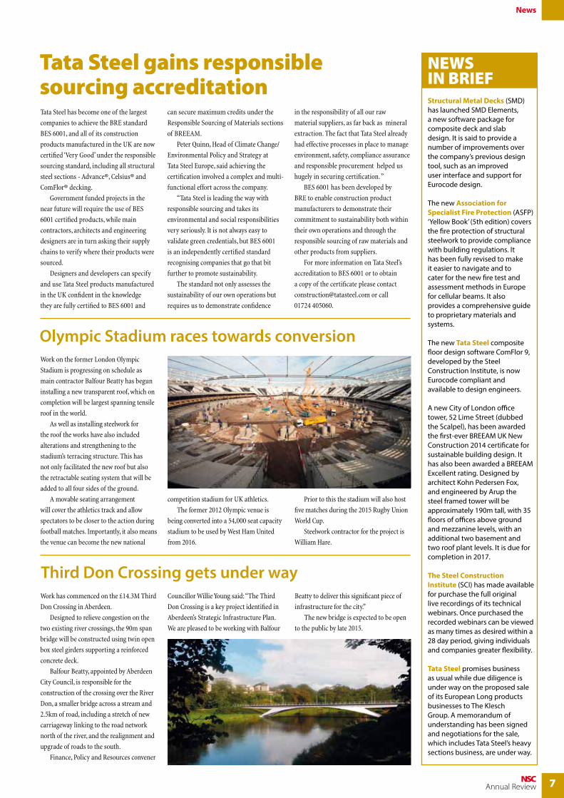
Olympic Stadium races towards conversionWork on the former London Olympic
Stadium is progressing on schedule as
main contractor Balfour Beatty has begun
installing a new transparent roof, which on
completion will be largest spanning tensile
roof in the world.
As well as installing steelwork for
the roof the works have also included
alterations and strengthening to the
stadium’s terracing structure. This has
not only facilitated the new roof but also
the retractable seating system that will be
added to all four sides of the ground.
A movable seating arrangement
will cover the athletics track and allow
spectators to be closer to the action during
football matches. Importantly, it also means
the venue can become the new national
Structural Metal Decks (SMD) has launched SMD Elements, a new software package for composite deck and slab design. It is said to provide a number of improvements over the company’s previous design tool, such as an improved user interface and support for Eurocode design.
The new Association for Specialist Fire Protection (ASFP) ‘Yellow Book’ (5th edition) covers the fire protection of structural steelwork to provide compliance with building regulations. It has been fully revised to make it easier to navigate and to cater for the new fire test and assessment methods in Europe for cellular beams. It also provides a comprehensive guide to proprietary materials and systems.
The new Tata Steel composite floor design software ComFlor 9,developed by the Steel Construction Institute, is now Eurocode compliant and available to design engineers.
A new City of London office tower, 52 Lime Street (dubbed the Scalpel), has been awarded the first-ever BREEAM UK New Construction 2014 certificate for sustainable building design. It has also been awarded a BREEAM Excellent rating. Designed by architect Kohn Pedersen Fox, and engineered by Arup the steel framed tower will be approximately 190m tall, with 35 floors of offices above ground and mezzanine levels, with an additional two basement and two roof plant levels. It is due for completion in 2017.
The Steel Construction Institute (SCI) has made available for purchase the full original live recordings of its technical webinars. Once purchased the recorded webinars can be viewed as many times as desired within a 28 day period, giving individuals and companies greater flexibility.
Tata Steel promises business as usual while due diligence is under way on the proposed sale of its European Long products businesses to The Klesch Group. A memorandum of understanding has been signed and negotiations for the sale, which includes Tata Steel’s heavy sections business, are under way.
NEWS IN BRIEF
Third Don Crossing gets under wayWork has commenced on the £14.3M Third
Don Crossing in Aberdeen.
Designed to relieve congestion on the
two existing river crossings, the 90m span
bridge will be constructed using twin open
box steel girders supporting a reinforced
concrete deck.
Balfour Beatty, appointed by Aberdeen
City Council, is responsible for the
construction of the crossing over the River
Don, a smaller bridge across a stream and
2.5km of road, including a stretch of new
carriageway linking to the road network
north of the river, and the realignment and
upgrade of roads to the south.
Finance, Policy and Resources convener
Councillor Willie Young said: “The Third
Don Crossing is a key project identified in
Aberdeen’s Strategic Infrastructure Plan.
We are pleased to be working with Balfour
Beatty to deliver this significant piece of
infrastructure for the city.”
The new bridge is expected to be open
to the public by late 2015.
competition stadium for UK athletics.
The former 2012 Olympic venue is
being converted into a 54,000 seat capacity
stadium to be used by West Ham United
from 2016.
Prior to this the stadium will also host
five matches during the 2015 Rugby Union
World Cup.
Steelwork contractor for the project is
William Hare.

8 NSCAnnual Review
SSDA 2014
The Awards aim to promote the innovative use of steel by rewarding outstanding projects and last year’s event, held at Madame Tussauds
in London, saw three projects win a coveted award: Holland Park School, London; Splashpoint Leisure Centre, Worthing; and The Kelpies, Falkirk. Television news presenter Emma Crosby compered the awards, which had been selected by the SSDA judges from the 12 finalists. All of the entries scored highly in efficiency, cost effectiveness, aesthetics, sustainability and innovation. Chairman of the Judges, David Lazenby CBE said: “The spread of the projects, both geographically and in types, reflects the broad appeal of steelwork in construction today.
Structural steel design awards highlight innovation The Structural Steel Design Awards (SSDA) scheme was instituted in 1969 to recognise the high standards of structural and architectural design attainable in the use of steel.
BCSA President, Wendy Coney
Chairman of the Judges, David Lazenby
Host, Emma Crosby
Tata Steel Europe Chief Technical Officer, Hans Fischer
AWARDS
Holland Park School, London
Splashpoint Leisure Centre, Worthing
The Kelpies, Falkirk
COMMENDATIONS
Gem Bridge, Dartmoor National Park
Red Bridge House, Crowborough
Scale Lane Bridge, Hull
20 Fenchurch Street, London
Loughor Viaduct Replacement,
South Wales
OTHER FINALISTS
ME Hotel, London
Visitor Centre, Stonehenge
First Direct Arena, Leeds
Reading Station Transfer Deck
“I have been considering what particular characteristics have come across to us forcibly this year. I think it is probably the sense of boldness and innovation – being prepared to think laterally – and for the teams to search for different ideas, and approaches, in order to achieve the optimum solution in the service of the client, the public and society. This increasingly impresses me, and all the judges.” He went on to say that all the projects, particularly the winners, will prove inspirational as we move forward into a better climate and environment for the industry. Commendations were awarded to five further projects: Gem Bridge, Dartmoor National Park; Red Bridge House,
Crowborough; Scale Lane Bridge, Hull; 20 Fenchurch Street, London; and Loughor Viaduct replacement, South Wales. Wendy Coney, British Constructional Steelwork Association President said in her address: “All of us here are familiar with the advantages and versatility steel brings, the particular qualities we can rely on it to deliver, and we all know that by specifying steel you are ensuring a high quality project that meets your sustainability, safety and programme needs. In closing the ceremony Hans Fischer, Chief Technical Officer, Tata Steel, said he was impressed, yet again, by the quality of the SSDA entrants and this was one of the reasons why the UK was Europe’s leading market for constructional steelwork.

9NSCAnnual Review
SSDA 2014
Located within a conservation area and adjacent to the Royal Borough of Kensington and Chelsea’s largest park, the
redevelopment of Holland Park School was a high profile project that called for a new building that neither looked nor felt like a traditional school. This was achieved by using a structural steel frame to create flexible and open plan spaces, while externally the school is sympathetic to its parkland neighbours with the addition of a striking façade made up of copper, brass and bronze. The new building is split into two banks of accommodation separated by a large glazed atrium. The basement houses the school’s largest spaces – a sports hall and a 25m-long, four lane swimming pool – as well as kitchen and dining areas.
In a prime seafront location and part of Worthing’s ongoing redevelopment, Splashpoint Leisure Centre is divided into two distinct parts, a two-storey
structure housing changing rooms, shower cubicles and a fitness centre, and a large steel framed zone that contains all the swimming facilities. The swimming pool areas are spanned by a dramatic sawtooth roof, with its ranks of sinuous ridges, recalling a series of dunes that curve and twist towards the coast. This concept, which won a RIBA design competition at the project’s inception, has been recognised at a global level as the project was also declared winner of the World Architecture Festival 2013 Sports Category. “The use of steel was fundamental to
A pair of 30m high tubular steel framed horse heads, known as The Kelpies, are one of the final elements of the Helix Project,
a scheme that has transformed a swathe of land between Falkirk and Grangemouth into a vibrant park with its own lagoon, outdoor events space, and a new turning pool and lock for canal boats. The Kelpies are made up of three elements – the primary frame, the secondary structure that extends from the primary frame to support the external skin and the stainless steel cladding that forms the skin itself. S H Structures fabricated as much of the steelwork offsite and brought it to Falkirk in the largest transportable sizes. The primary main frame is made of sub frames that weigh up to 10t and have maximum measurements of 4.5m wide x 12m long. It was impractical to trial erect both heads complete, but adjacent sub frames were matched to ensure a first time fit could be achieved on site.
FACT FILEHolland Park School, LondonArchitect: AedasStructural engineer: Buro Happold LtdMain contractor: Shepherd ConstructionClient: The Royal Borough of Kensington and Chelsea
FACT FILESplashpoint Leisure Centre, WorthingArchitect: Wilkinson Eyre ArchitectsStructural engineer: AECOMSteelwork contractor: Severfield UK LtdMain contractor: Morgan SindallClient: Worthing Borough Council
FACT FILEThe Kelpies, FalkirkSculptor: Scott SculpturesStructural engineer: JacobsSteelwork Contractor: S H Structures LtdMain contractor: S H Structures LtdClient: The Helix Trust
© J
ulia
n A
bram
s
© D
anie
l Hop
kins
on o
f Aed
os
achieving the project’s architectural concept as the material is ideally suited to provide for the sculptured roof form and to create
the 50m clear span for the main swimming pool area,” said AECOM Regional Director – Structures Matthew Palmer.

10 NSCAnnual Review
Perched on the City of London’s eastern boundary, Aldgate has for a long time been overshadowed by the square mile’s many ultra
modern steel and glass high rise buildings. However in recent times a number of developments have helped to regenerate this part of east London and, combined with its proximity to the City, Aldgate is now a desirable place to live and work. Adding to the area’s stock of commercial office space is an 18-storey structure known as Aldgate Tower developed by Aldgate Developments and built by Brookfield Multiplex. Designed to a BREEAM ‘Excellent’ rating, the building provides 16 floors of Grade A office space, plus two upper levels
for plant equipment. Below ground the structure is founded on an existing three level reinforced concrete basement raft, a feature that has had an overwhelming impact on the design and construction of the tower. The raft was constructed in 1982 for a previous development, and RBS the project’s neighbour uses the majority of the lower two floors of the basement for its canteen and office storage. “As the raft is in use it had to be retained and incorporated into our design,” explains George Amy, Brookfield Multiplex Project Manager. “This meant we had to use a framing material for the new building that could be safely and quickly erected above functioning office space.”
A steelwork solution was the answer, as the material not only helped the contractor to build over RBS’s subterranean facilities, it also allowed the new structure to be considerably higher than the originally proposed structure. Steelwork’s lightweight attributes consequently allowed the construction project to achieve its aim of increasing the lettable office space, while incorporating an existing basement. “A steel frame supporting metal decking offered us the lightweight solution we required,” explains Ben Tricklebank, Arup Project Engineer. “However, just as important was the fact that steel trusses could be quickly erected over the RBS delivery road at night without disrupting its use.” However, building on top of the raft meant a traditional concrete core in the middle of the tower was not feasible. The answer was steel yet again, and the installation of a 9m x 20m braced core to stabilise the overall frame. This was erected at the same time as the rest of the steelwork, allowing a faster erection programme. The steel core starts at ground floor and sits on a transfer structure, comprising of 47t beams that distribute the loads to the raft’s concrete columns. At ground level the core frame’s columns are offset to allow the
Aldgate rising A steel solution has allowed the construction of an 18-storey commercial development to be built on top of an existing raft foundation originally designed to support a smaller building. Martin Cooper reports from east London.
FACT FILEAldgate Tower, LondonMain client: Aldgate DevelopmentsArchitect: Wilkinson Eyre ArchitectsMain contractor: Brookfield MultiplexProject manager: FtsquaredStructural engineer: ArupSteelwork contractor: SeverfieldSteel tonnage: 5,600tProject Value: £78M
Commercial
Part of the building is positioned over an entrance to Aldgate East Underground Station
11NSCAnnual Review
Commercial
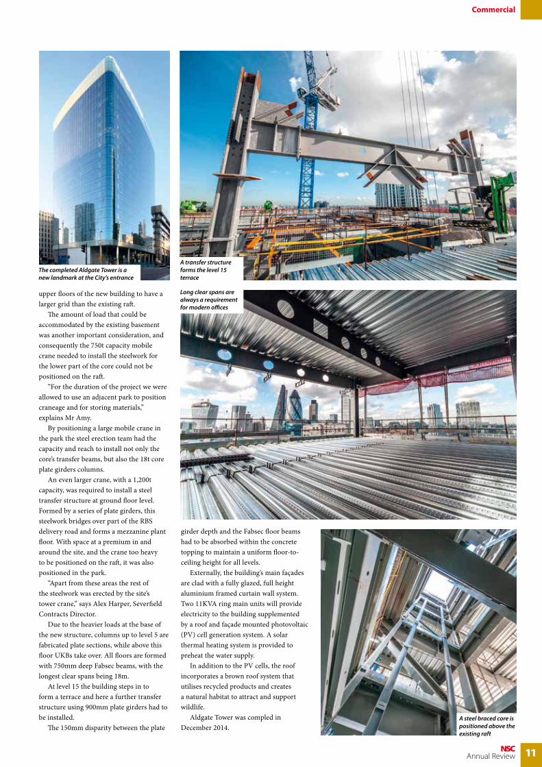
upper floors of the new building to have a larger grid than the existing raft. The amount of load that could be accommodated by the existing basement was another important consideration, and consequently the 750t capacity mobile crane needed to install the steelwork for the lower part of the core could not be positioned on the raft. “For the duration of the project we were allowed to use an adjacent park to position craneage and for storing materials,” explains Mr Amy. By positioning a large mobile crane in the park the steel erection team had the capacity and reach to install not only the core’s transfer beams, but also the 18t core plate girders columns. An even larger crane, with a 1,200t capacity, was required to install a steel transfer structure at ground floor level. Formed by a series of plate girders, this steelwork bridges over part of the RBS delivery road and forms a mezzanine plant floor. With space at a premium in and around the site, and the crane too heavy to be positioned on the raft, it was also positioned in the park. “Apart from these areas the rest of the steelwork was erected by the site’s tower crane,” says Alex Harper, Severfield Contracts Director. Due to the heavier loads at the base of the new structure, columns up to level 5 are fabricated plate sections, while above this floor UKBs take over. All floors are formed with 750mm deep Fabsec beams, with the longest clear spans being 18m. At level 15 the building steps in to form a terrace and here a further transfer structure using 900mm plate girders had to be installed. The 150mm disparity between the plate
girder depth and the Fabsec floor beams had to be absorbed within the concrete topping to maintain a uniform floor-to-ceiling height for all levels. Externally, the building’s main façades are clad with a fully glazed, full height aluminium framed curtain wall system. Two 11KVA ring main units will provide electricity to the building supplemented by a roof and façade mounted photovoltaic (PV) cell generation system. A solar thermal heating system is provided to preheat the water supply. In addition to the PV cells, the roof incorporates a brown roof system that utilises recycled products and creates a natural habitat to attract and support wildlife. Aldgate Tower was compled in December 2014.
A transfer structure forms the level 15 terrace
Long clear spans are always a requirement for modern offices
The completed Aldgate Tower is a new landmark at the City’s entrance
A steel braced core is positioned above the existing raft

12 NSCAnnual Review
Energy
One of the largest building projects in recent times in the Republic of Ireland was the construction of a replacement
460MW combined cycle gas turbine (CCGT) power station located adjacent to the confluence of the River Suir and River Barrow near Waterford. Project client SSE says by replacing the site’s existing 240MW fuel oil unit this modern natural gas fired power station will significantly reduce the locality’s carbon emissions. CCGT power generation is said to be the most energy efficient and cleanest method of fossil fuel generation. It involves burning natural gas, which turns a gas turbine with the heat generated used to power a steam turbine. Structural steelwork played a leading role in the construction of the project’s turbine building and electrical building, as they need to be large open column free spaces, in order to accommodate large pieces of generating equipment. Both of these two main structures are founded on reinforced shallow pad foundations, while deep piled foundations have been used for the other structures due to poor ground conditions.
“The choice of steel as the main framing material is based on both economy and versatility,” says Santiago Paje, Initec Energia Chief Designer for Civil Engineering. Long span economic structures were required for this job and steelwork provided the solution. Steelwork’s flexibility also came to the fore as the design developed even after the erection started. “Steel has the ability to be quickly and economically erected with large spans which can absorb big loads. Steel frames are also versatile enough to be continually redesigned, which is what happened on this project as the frame design was altered and modified while it was being constructed,” adds Mr Paje. The inherent flexibility of bolted structural steelwork has been key to the design of the turbine building. Mr Paje says this will allow certain bays of the steelwork frame to be removed if large pieces of equipment need to be removed and replaced. Standing 25m high the turbine building is the largest building on the site and has been formed with a series of fabricated columns. “Each of the columns weighs in excess of 9t as they also support crane beams running
the length of the structure,” explains John Kiernan of Kiernan Structural Steel. “Consequently these plate columns have large 40mm flanges and 60mm thick baseplates that have full penetration butt welds.” To accept the crane beams the columns have welded stubs at a height of 22m. The crane beams measure 1,400mm deep × 400mm wide and were brought to site in 13.5m lengths, which corresponds with the width of the building’s bays. The columns also support 29m long roof trusses, which in turn create the large open column free space needed for the turbine hall. The 3m deep trusses were brought to site in two pieces (one 10m long section and one 20m long section), bolted together on the ground before being lifted into place as a complete unit. The turbine building has been designed as a portalised frame with the addition of bracing in some bays. Fixed supports were required in both directions as wind and crane loads are expected to be very substantial. Inside the turbine building there is an mezzanine level running alongside three elevations while a lean-to storage structure is attached to two façades of the building.
A power station constructed at Great Island, County Wexford will provide electricity to approximately 220,000 houses in south eastern Ireland.
Steel powers energy designThe project has included
improvements to the site’s waterfront defences

13NSCAnnual Review
Energy
FACT FILEGreat Island Power Station, Wexford, Republic of IrelandMain client: SSEArchitect: InitecMain contractor: Dragados-Cobra-Initec (Joint Venture)Structural engineer: Initec EnergiaSteelwork contractor: Kiernan Structural SteelSteel tonnage: 3,300t
The steel erection process saw Kiernan Structural Steel use a combination of 200t and 80t capacity mobile cranes. The programme lasted nearly one year and Kiernan Structural Steel had to be flexible with its programme schedule. “When we erected the turbine hall we had to leave out one gable end section so the turbines could be installed,” says
Mr Kiernan. “Only after this large scale mechanical equipment installation operation had been completed could we finish erecting the final parts of the turbine hall’s frame.” Prior to in-filling the gable end of the turbine hall, and while the turbines were being installed, Kiernan Structural Steel erected the electrical building and various
other smaller buildings and pipe racks located around the site. “It was a very challenging project,” sums up Mr Kiernan. “We had to schedule our deliveries and erection programme, including working night shifts, in order to accommodate a number of other trades and professions. Access and space around the site was very confined and challenging.”
Inclement weather has not hindered the construction project
One of the steel frames supports a flue
The electrical building being erected
The steelwork for the turbine hall was completed around equipment installation
Cladding systems are installed to the turbine hall

14 NSCAnnual Review
Distribution
Due to ever increasing demand for its services, UK and International parcel delivery provider DPD UK is building
its fourth and largest hub in the United Kingdom. The company currently has three large main parcel sortation hubs at Smethwick and Oldbury in the West Midlands, locations that are conveniently located in the centre of the country with easy access to the M6 motorway. The new facility at Hinckley also has good motorway access and should be fully operational in 2015. It will create up to 1,000 jobs, increasing DPD’s overnight parcel sorting capacity by as much as 65%. The structure is huge and measures
480m long × 40m wide. Internally it has a 30m wide clear span, formed by a series of tapered lattice trusses that have a maximum depth of 5m. The trusses are important, not just forming the roof, but also supporting a steel grillage that will in turn support the hub’s conveyor system. In most similar installations the conveyor would be supported off the ground floor slab by an extensive system of support frames provided by the conveyor supplier. This format significantly reduces the clear circulation routes and operating efficiency of a facility. “To avoid this the client required us to design the building frame to support the conveyors without the need for internal supports. It is believed that the company’s Hub 3 and this new Hub 4 are the only such facilities in Europe to be designed in this manner,” says Neil Darroch, Cameron Darroch Associates Project Engineer. “In effect the client has paid an initial
One of the UK’s fastest growing parcel firms is constructing a new £100M facility in the East Midlands.
Steel delivers parcel hub
The latest DPD UK hub at Hinckley forms part of a new business park being
developed by Goodman. As well as the main building, the hub also consists of
four other structures, all of which are formed with steelwork.
A four-storey gatehouse, with a footprint of 20m x 37m, is the largest of these
structures. Constructed around a standard beam and column grid the building will
accommodate three floors for security, offices, a canteen and staff welfare facilities,
with the top level used for plant equipment.
The other on site structures consist of a portal framed vehicle maintenance unit
with attached offices, a garage/tyre store and salt barn building, and a vehicle jet
washing facility.
Parcel delivery hub
Caunton has also installed six external staircases
Caunton erected the frame sequentially and left a completed frame for the follow on trades

15NSCAnnual Review
Distribution
premium for the building to maximise long term operational efficiencies. Steel was the only feasible option to allow us to meet the client’s brief.” The structural steel frame of the hub is based around 72 × 6.35m wide bays, with each bay large enough to accommodate four loading doors – two on each side of the building. Stability is derived from the portal action within the trusses and bracing located in some bays. The steel grillage hung from the trusses is not based on the standard grid pattern. These columns are mostly set off grid and were all designed with the conveyor system in mind. “The steelwork can’t interfere with the building’s all important conveyors or any internal traffic movements,” explains Mr Darroch. “Consequently the hanging columns are all set at various points so as not to clash with any of the sortation plant.” Aside from the main sorting area of the hub, the remainder of the structure’s width is formed by a series of 10m long rafters that share a row of internal columns for support. The rafters support the roof over a two-storey office mezzanine that extends throughout the 305m long central portion of the hub, while either side of this shallower lattice girders support single-storey timber decked mezzanine floors required for the parcel in-feed areas. The timber areas required steelwork contractor Caunton Engineering to erect a system of cold rolled C-sections, spanning between hot rolled primary beams suspended from lattice girders forming
the roofs. The office mezzanine levels are constructed with a more traditional composite steel beam and steel flooring configuration. “Because of the overall length, we divided the building into four phases for our erection programme,” says Bob Aitman, Caunton’s Erection Manager. “Using two mobile cranes we erected two trusses and their columns, then in-filled the hanging steelwork and then installed the connecting
rafters and mezzanine sections. We would then repeat this format until each phase was completed.” Apart from the trusses, which arrived on site in two pieces, all of the steelwork for this project was immediately ready for erection once it was delivered. By working its way systematically down the structure, Caunton was able to leave a completed frame ready for follow-on trades to get started as quickly as possible.
The office mezzanine is formed with metal decking
FACT FILEDPD UK parcel hub, HinckleyMain client: DPD UKArchitect: Stephen George & PartnersMain contractor: Winvic ConstructionStructural engineer: Cameron Darroch AssociatesSteelwork contractor: Caunton EngineeringSteel tonnage: £2,300t
The steel erection programme well under way

16 NSCAnnual Review
Education
One of the largest developments to take place in the north of Scotland for many years is under way in Inverness.
Described by Highlands and Islands Enterprise (HIE) – the Government quango responsible for local commerce and development – as a once in a lifetime opportunity, the Inverness Campus could generate around £38M for the regional economy each year and provide work for more than 6,000 people. Overall the scheme is split into three
phases (see box), with the initial part of the work centred on a new home for Inverness College. One of 13 colleges and research institutions that make up the University of the Highlands and Islands, the new premises will allow Inverness College UHI to vacate its old buildings and take possession of state-of-the-art facilities. Located in the centre of the first phase, the new college building will act as a focal point for the entire Campus as it is by far the largest single structure in the development.
Spread over three storeys, the completed building will offer more than 20,000m2 of teaching and workshop space for some 6,500 students. The building uses the diaphragm of the floor plate to transfer horizontal loading from the steel frame to the six braced steel cores. Where required, cross bracing has been provided within partition walls to give additional stability. “The steelwork supports steel decking and we went for this composite design as it was considered to be the quickest and lightest solution,” says David Trahar, Struer Project Director. The weight of the structural frame was an important consideration, not just because it would be more cost-effective, but also because its lighter weight meant that pad foundations could be used and piling avoided. A standard 6m grid pattern has been used throughout the structure with only a few areas needing to have a variation. The unorthodox shape of the building – it is
Steel heads campus examinationFast lightweight construction is the order of the day for a new college project in the Highlands. Martin Cooper reports from the initial project for the ambitious Inverness Campus scheme.
FACT FILEInverness College UHIMain client: Miller Equitix InvernessArchitect: BDPMain contractor: Miller ConstructionStructural engineer: StruerSteelwork contractor: BHC Steel tonnage: 1,400t
Three large rooftop pods will house the college’s plant equipment
The largest project within the Inverness Campus takes shape

17NSCAnnual Review
Education
Bridge to the Campus
roughly kidney-shaped with the addition of one long straight elevation – meant a lot of time was taken with the setting of column lines, particularly around the structure’s corners. “It is a difficult shape and we had to pass the structural model back and forth between ourselves and the engineer in a BIM (Building Information Modelling) exercise, in order to get it right,” explains Stephen Kelly, BHC Drawing Office Manager. Using BIM also made the steel frame’s design cost-efficient as cellular beams have only been used where needed for service integration. The BIM model quickly showed where these areas were, an exercise that helped save money. Craig Paterson, Miller Construction Project Director agrees: “The geometry is complex and using BIM ensured the steel frame was as flexible and as cost-effective as possible.” The project does have some long spans such as the main entrance and its adjoining full height atrium. Creating this large open area is a series of 21m long beams, spaced at 6m centres and supporting roof lights. Another long span area is the first floor sports hall, where 17m long column free spans were needed to accommodate badminton and squash courts. Maximising space as well as making sure the gym would be accommodated within the main structure led to the decision to put it at first floor level as opposed to the ground floor, allowing the area below the hall to be occupied by workshops. An economic design has been achieved as the sports hall’s 17m long beams only have to support the roof. If the facility had been located at ground floor level, a series of less economic transfer structures would have been required to support not only the roof but also a floor of workshops. Befitting the centrepiece building of the Campus, it has a number of architectural features. Adorning the top of the building are three pods used as plant enclosures but initially designed purely as architectural highlights. The pods are different sizes, but all elliptically shaped, with the biggest measuring 40m long and 9m high. Supported by the building’s roof steelwork, the pods are formed with a series of curved hollow section rings that will be clad with a copper mesh. The building’s roof also overhangs the main elevation and this feature ends with a prow that covers the main thoroughfare into the entrance. A series of four 14.5m high V-shaped CHS columns support the overhang. A slightly larger 17m high V-shaped section stands guard in front of the entrance supporting the upturned prow. Inverness College UHI is scheduled to open in September 2015.
The scheme is being developed on a 215 acre site just off the A9 dual carriageway on the outskirts of the city. It is located adjacent to the Raigmore Hospital (the region’s largest NHS infirmary) and Lifescan Scotland, a manufacturer of scanners and currently the biggest employer in Inverness.
The vision is for the Campus and its neighbours to forge an alliance and form a key research and education environment. As well as the College (A), phase one of the Campus project includes a four-star hotel (B), student accommodation blocks (C), offices and research space (D). Designs are currently being finalised and the likelihood is that steel will play a role in most of these schemes when they get started later this year. Two further phases are planned: phase two (2) will include leisure and sport facilities, and more office blocks, while phase three (3) will be residential. Throughout the scheme, positive measures will be taken to be sympathetic towards the natural environment. “The Campus will have parkland, recreational space for people working and studying on site as well as for the wider local community,” says Ian Thorburn of the Highlands and Islands Enterprise. “Public art features will further develop the high quality landscape for all to enjoy.”
The Inverness Campus
A
B
C
D
32
Linking the Campus with Inverness city centre is an 84m long single span steel pedestrian and cycle bridge that crosses the A9.
This important link was fabricated and assembled by Cleveland Bridge. It is 9m wide, weighs 290t and was brought to site as six main girders, two measuring 36m long and four 24m sections. “We assembled the bridge on 2m high stillages on an adjacent site,” says Paul Walmsley, Cleveland Bridge Project Manager. “We welded the girders
and crossbeams, as well as installed the metal deck.” Once the bridge was assembled and clad, Morgan Sindall (the main contractor for the Campus infrastructure works) and heavy lift specialist Mammoet, installed the bridge during a weekend road closure. The bridge structure was jacked up and transported from its assembly yard to its permanent position by self propelled mobile transporters, and then lowered onto its permanent bearings. The bridge was officially opened in April 2014.

SafetySteel construction has a safety record that is the envy of the construction industry; it is inherently safer than using other framing materials for a large number of reasons. Most of the work involved takes place offsite under controlled and regulated factory conditions and fabricated steel is only brought to site when needed, avoiding potentially dangerous clutter that often bedevils sites where concrete shuttering and other materials have to be stored.
• Fewer people are needed on site, reducing the risk of accidents
• Skilled and trained erection teams focus on safe working practices
• Accurate offsite fabrication reduces the amount and handling of waste
• On site pre-assembly can further reduce the number of lifting operations and reduce the need to work at height
Steel ticks all the boxesSteel has many benefits that deliver value to designers, contractors, developers and building users. Most arise automatically once the decision to build in steel is made, and at no extra cost.
18 NSCAnnual Review
The Right Choice
• Steel provides the earliest start on site, and fabricated steel is delivered to site only when needed
• Steel erection on site is fast leading to savings in site preliminaries
• Time related savings can amount to between 3% and 5% of the overall project value
• Speedy erection makes way for other critical path operations
QualitySteel construction provides most of the modern iconic multi-storey buildings where high quality is expected as a minimum requirement and provides the surest guarantee that the end product will allow design visions to be delivered. Quality assurance runs throughout the supply chain, where steel sections are manufactured, tested and certified to national and international standards. Steel sections will be CE Marked and delivered with inspection certificates.
• Steel can be easily and safely modified if changes are needed when erection is under way
• Steel frames are full strength as soon as they are completed so stairs can be fitted, providing safe access for other trades straightaway
• Steel decking for composite slabs provides a safe platform after installation, as well as protection to lower storeys
SpeedFast and safe erection of steelwork provides cost and time saving advantages that are unachievable with other methods of construction. Offsite fabrication means right-first-time accurate production that eliminates time wasting reworking. The speed benefits of steel deliver advantages to projects of all sizes, from the simplest shed to the most complex structures that can use offsite trial erections to ensure that everything can go right on the day.
Distribution centres are predominantly built with steel for its long span qualities and speed of construction

19NSCAnnual Review
The Right Choice
• Fabrication processes are quality assured and fully CE Marked
• In the factory, the use of leading edge 3D modelling and numerically controlled fabrication systems delivers precision-engineered components to tight tolerances
• All BCSA steelwork contractors are regularly assessed for their technical capabilities and financial standing
CostSteel is the most cost-effective framing material and delivers proven, inherent cost advantages for buildings and structures of all types. Steel is cheaper than it was 15 years ago in inflation adjusted terms, and has fallen in price since 1980.
• Productivity advances have also been achieved throughout the steel supply chain and the cost saving benefits shared with customers
• Independent studies show that on a typical multi-storey office building, a steel composite beam and slab option has both the lowest frame and upper floors cost and lowest total building cost
• Conversely, the reinforced concrete flat slab option has the highest overall building cost
Efficiency Steel designs are structurally efficient, taking advantage of the high strength-to-weight ratio of steel. This has many follow-on benefits, including:
• Better utilisation of space • Longer flexible internal column free
spaces• Foundations that are lighter and
cheaper• Steel is fabricated offsite to tight
tolerances and brought to site for erection with virtually no waste
• Lean manufacture within an integrated supply chain gives a more predictable construction programme
• Design changes can be accommodated at any time
SustainabilitySteel is the sustainable choice for structural use. It is the world’s most recycled material and 99% of structural steel used in the UK is recycled or re-used – none will ever go to landfill as waste. Steel is multicycled, meaning that it can be used again and again without suffering any loss of quality.
sector and fire protection manufacturers means that proven cost-effective fire protection measures are always being improved.
• Advanced design and analysis techniques allow precise specification of the fire protection requirements of steel-framed buildings, often resulting in significant reductions in the amount of fire protection required
• Methods are available for the analysis of composite steel deck floors in fire, which can lead to the elimination of fire protection on many secondary beams
• The UK has a competitive and very effective fire protection industry
• Thin film intumescent coatings are now the most popular form of fire protection in the UK, and a successful offsite application sector using this material has been developed
BIMThanks to its early adoption of computer aided design and computer numerically controlled production techniques the steel construction sector has a head start with BIM, playing an active role in the supply chain as it moves towards meeting government targets for its introduction. From 3D modelling as standard practice to early design collaboration, many steelwork contractors have already delivered BIM projects.
• Steel buildings are adaptable and flexible
• Offsite production is inherently safer than on site construction, and local communities appreciate reduced dust and noise
• Signatory companies to the BCSA’s Sustainability Charter agree to their sustainability credentials being assessed and monitored
• Independent research shows that almost all steel framed buildings can provide optimal thermal mass, as they provide the required 75-100mm thickness of concrete floor slab
AcousticsSteel framed buildings easily satisfy the acoustic performance requirements for residential buildings, as set out in Approved Document E. Steel has been selected by well informed designers and clients for many prestigious residential projects and hotels. For external walls, where both acoustic and thermal insulation must be provided, infill steel framed construction is the perfect solution.
VibrationIndependent research proves that for most office buildings straightforward steel construction systems will meet the required vibration performance criteria without any special or additional measures being adopted. For extremely vibration sensitive applications like hospital operating theatres floors extra stiffening can be applied to the steel frame.
• Even with these additions steel remains the most cost-effective and lightweight solution
• Long-span applications, for which steel is the only option, have been found to offer excellent vibration damping
• Detailed studies have shown that steel-framed buildings provide floors with vibration performance that meets or exceeds the NHS stringent vibration specifications, while still achieving economy and flexibility in use
Fire ProtectionThanks to extensive tests carried out by the Building Research Establishment in the 1980’s and the observation of what happens to building structures in real fires, more is understood about the behaviour of steel in fire than any other construction material. A continuous programme of investment and research by the steel
The use of structural steelwork and edge protection provides an inherently safer construction environment

20 NSCAnnual Review
Healthcare
Situated on the south bank of the River Thames, facing the Houses of Parliament, St Thomas’ Hospital has been an important London
landmark since moving to its present location in 1871. Originally established in the Middle Ages on a site near London Bridge, it has a long and distinguished history and today St Thomas’ is a world renowned teaching hospital. The appearance of the current site has changed a lot over the years, as many of the original Victorian wards were destroyed during the Second World War and a number of new structures were added in the 1950s and 60s. One of these more recent additions is the concrete framed 13-storey East Wing tower, a building opened in the early 1960s and unfortunately blighted by water penetration for most of its lifetime. To solve this building’s structural problem, transform its appearance and improve the functionality a £27M project will give the tower a new glazed façade, two atria and a new shape. The project includes the installation of new
Steel cure for hospital The East Wing building at St Thomas’ Hospital has historically been blighted by water ingress. In order to remedy the situation the structure is being re-clad with steel and glass. Martin Cooper reports.
FACT FILESt Thomas’ Hospital East Wing project, LondonMain client: Guy’s and St Thomas’ NHS Foundation TrustArchitect: Hopkins ArchitectsMain contractor: ISGStructural engineer: ArupSteelwork contractor: Bourne SteelSteel tonnage: 300tProject Value: £27M
The project includes new rooftop steelwork that will support glazing on the western façade while further additions of structural steelwork will infill the T-shaped building with two atria.
Visualisation of one of the new atria
rooftop steelwork that will support glazing on the western façade (overlooking the Houses of Parliament), while further additions of structural steelwork will infill the T-shaped building with two atria creating an on-plan half diamond-shaped structure. Main contractor ISG’s work also includes restoring the existing building’s exterior slate cladding and teak windows. These elevations will now be essentially interiors, inside the new atria or protected from the elements by the western façade. Actually getting materials on site has been one of the main challenges for the construction team. Work has been
complicated by the fact that the East Wing is located at the heart of the hospital campus, surrounded by other buildings and lacking direct access routes for large deliveries of plant or materials. The 200-bed capacity building accommodates cardiology services, two intensive care units, admission wards alongside clinical suites and offices, teaching facilities and ancillary plant and storage areas. Throughout the duration of the project all of these facilities have to remain fully operational adding another unique challenge to the construction project. To overcome the access problem ISG set up a tower crane adjacent to the East Wing to undertake a lot of the lifting, with no room on site for any other cranes. As far as helping to keep the hospital facilities working as normally as possible ISG has a number of ongoing strategies. Fraser Tanner, ISG Senior Project Manager explains. “We are in constant consultation with the hospital to mitigate potential disruption and communicate with hospital staff on a daily basis to advise when and where we will be working.”

21NSCAnnual Review
Healthcare
Using structural steelwork for this project has been advantageous as the tower crane can lift most of the elements straight into position so they can be erected immediately upon arrival, and by prefabricating some steel elements the team has reduced the amount of on site work and the possibility of unwanted noise. Bourne Steel has fabricated, supplied and erected much of the project’s steelwork, including a prefabricated and modular lift shaft to accommodate two new patients lifts in the eastern atria. “We fabricated, delivered and installed the shaft in two-storey high modules which were light enough for the tower crane to lift into position before they were bolted into place,” explains Kevin Clarke, Bourne Steel Divisional Director. Prior to installing the lift shaft, Bourne Steel erected the floor steelwork for the two atria. Formed with a series of 600mm × 400mm jumbo box sections they have been installed at second floor level above a triple height basement. Supporting the floors are CHS columns and one feature Y-shaped column at the front that also supports the atria glazing. “The positioning of the columns is very irregular and their installation was one of the biggest challenges due to the amount of services hidden below the site,” explains Christian Dercks, Arup Structural Engineer. Each of the triangular atria floors cantilevers 2m at the southern tip over low level adjacent buildings. A 1.2m deep truss in each atria supports the cantilevers via bolted connections to the existing East Wing structure. The trusses have to support ten levels of atria and are consequently formed from large 400mm × 400mm box sections. Forming the outside elevation of the triangular atria are 30m long CHS trusses positioned at every second floor. Brought to site in three sections, these trusses were welded on site before being lifted into place and fixed to the existing building via bolted connections. The atria roofs will be constructed from ETFE cushions in a rhomboid configuration to shade direct sunlight from the south, while permitting softer indirect light from the north to naturally illuminate the internal space.
The East Wing project was procured via a high profile RIBA competition to select an architect and main contractor team that could transform the poorly performing building with a modern cladding solution to enhance
its environmental performance, upgrade facilities for patients and staff, and dramatically improve the building’s aesthetics on the capital’s skyline. The 2010 competition was won by a team comprising of ISG and Hopkins Architects, who have since worked closely with Arup to develop their plans for the building.
Competition kick starts project
Meanwhile the second steelwork element of the project is the new roof and hanging façade for the west elevation. Bourne Steel has erected a new roof with a series of 15m long rafters that cantilever out by 2.5m. From these rafters a lightweight steel grillage supporting maintenance balconies for each floor is hung via stainless steel tie rods. The front of the grillage is glazed forming a new bright and watertight façade. Sustainability and environmental performance are also key aspects of the ISG and Hopkins Architects solution, and the re-clad design incorporates a range of passive controls to maintain comfortable ambient temperatures within the building.
Stainless steel rods support the façade’s steelwork
One of the atria’s trusses is assembled before being lifted into place
Diagram showing thesteelwork additions tothe East Wing

Transport
22 NSCAnnual Review
Serving more than 54m passengers every year London Bridge railway station is one of the UK’s busiest transport hubs and one that is
predicted to get busier year on year. To cope with the increasing number of passengers the station is being redeveloped as part of the government sponsored £6.5bn Thameslink Programme. The work includes converting three of the nine terminating platforms to through platforms. This – along with the installation of a new viaduct – will remove a notorious bottleneck to the west of the station. More trains will run with Tube-like frequency, every 2-3 minutes at peak times, through central London by 2018, while pressure on the Underground network will be eased. All 15 platforms are being rebuilt to be covered by strikingly designed undulating canopies of steel and aluminium, incorporating clerestorey windows with north-facing glass that will let light flood the platforms and the new and larger concourse being built directly below at street level. Dave Ward, Network Rail Route Managing Director, says: “This huge investment in rebuilding London Bridge station will transform rail travel for millions of people across London and the south east.
Station redevelopment on track with steelLondon Bridge station is being completely rebuilt in a rolling programme that allows it to remain open for business at all times. Martin Cooper reports on steelwork’s important role.
FACT FILELondon Bridge station redevelopmentMain client: Network RailArchitect: GrimshawMain contractor: CostainStructural engineer: Hyder WSP JVSteelwork contractor for bridge decks: Cleveland BridgeSteelwork contractor for platform canopies: Severfield Steel tonnage: 7,000t
The canopy
is supported by a series of
Y-shaped columns

23NSCAnnual Review
Transport
By 2018, London Bridge will be the most modern station in Britain with more space, better connections and great facilities. “Keeping London Bridge open for passengers while we rebuild it is a critical and challenging part of the Thameslink Programme. Construction goes on as much as possible behind the scenes without impacting on passengers. But there will be times each year between now and 2018 when services into the station will need to change.” To keep passenger disruption to a minimum, the works are being undertaken in a sequential manner, with platforms being upgraded two at a time, thereby leaving the station with 13 ‘live’ platforms throughout the construction programme. Central to the project is the creation of the new concourse that requires some of the Victorian arches on which London Bridge station is founded to be demolished. They are being replaced with new steel bridge decks to support the platforms and rail tracks. This will create a new ground level concourse that will be larger than the pitch at Wembley Stadium and will provide more space and easier connections to rail services located above. Typically the programme follows a rou-tine schedule with demolition work leading the way. Once the arches supporting two platforms have been removed, groundworks for the new concourse will start, allowing steelwork contractor Cleveland Bridge to begin erecting new bridge decks to replace the arches. “In total we will erect 29 bridge decks (spans) during a number of sequential visits, adding up to about 4,000t, with the last ones erected in early 2017,” explains Ben Binden, Cleveland Bridge Project Manager. “Each of the visits requires us to erect either three or four decks depending on their position.”
Three pairs of 910mm deep plate girders, up to 30m long and weighing 55t, form each deck. “There is very little room on site, so once a pair of fully welded girders arrive on site they are lifted into place immediately,” says Mr Binden. “We erect the three or four spans in one eight to 14 day programme and then leave site and wait to be called back when the overall construction schedule has moved onto the next set of arches.” Once the bridge beams and bracing are in place, main contractor Costain casts the decks, encasing the beams but leaving the bottom flange exposed. The decks then form the slab supporting the new tracks and precast platform units, while the bot-tom flange, which is weathering steel, is covered with cedar cladding as part of the concourse roof. “Weathering steel was chosen for the bottom flanges because it won’t need to be painted in the future,” explains Peter Anstock, Structural Lead for Hyder WSP. “This cuts down on maintenance work and the future need to close areas of the concourse for repainting works.” Steel is also playing a leading role on top of the bridge decks where Severfield is delivering a further 3,000t of steelwork. “Our steel erection programme begins with a connection to Cleveland’s bridge decks,” explains Nick Scott, Severfield Contracts Manager. “This steel, that we call the ‘elephant’s ears’, supports a steel plinth that acts as a mounting for the precast
platform units and the canopy columns.” Once the precast platform units have been installed, which is also part of Severfield’s remit, the company then has to erect a series of 3.8m high Y-shaped columns spaced at 15m centres. The columns are connected via spine beams that help support a series of prefabricated steel cassettes (see box above), that in turn form the station’s feature curving canopy as well as accommodating services. In order to ensure the erection programme ran as smoothly as possible Severfield has undertaken a trial assembly of a 54m long canopy prior to starting work on site. “Future maintenance of the canopy could have been an issue for the client, the trial assured Network Rail that they could easily gain access to the services once the project was completed,” adds John Parker, Senior Technical Director for Hyder WSP. The redevelopment of London Bridge station will complete the wider London Bridge Quarter scheme, a high profile project that also includes The Shard, The Place and a new bus station.
“This huge investment in rebuilding London Bridge will transform rail travel for millions of people.”
In total 1,200 prefabricated steel cassettes will be installed by Severfield, with each one a bespoke unit due to the changing rooftop geometry. They are 9m deep by 3m wide and fabricated
from galvanized I-section rafters. Once they have been assembled at Severfield’s Bolton factory the project’s M&E contractor installs the services and the cladding contractor, using Kalzip roofing, forms the cassette’s individual canopy roof.
The completed cassettes are then delivered to site in loads of up to three units per truck and because they only weigh 2.5t each they are lifted into place by one of the site’s tower cranes.
Severfield is producing about 10 of these units every week and Network Rail estimates that the prefabricated cassettes are saving weeks off the programme, as less on site work is required.
Prefabricated cassettes cut on site work time
A total of 29 bridge decks will be installed by Cleveland Bridge
View of underside of bridge decks showing the mountings, known as the elephant’s ears, that support the platforms above

24 NSCAnnual Review
Amajor ten-year investment programme that will revitalise the renowned St James’s area of London with a new public
square, offices, retail outlets and high quality residences is under way The flagship of this multi-million pound vision is the St James’s Market scheme, just south of Piccadilly Circus, that will deliver 24,100m2 of commercial and retail space across two eight-storey blocks situated between two of London’s most prestigious thoroughfares, Regent Street and Haymarket. One of the eight-storey buildings at 14-22 Regent Street will feature a retained façade, allowing the new structure to fit seamlessly into its historic streetscape. Behind the façade a new steel framed structure will be erected accommodating retail at basement and ground floor levels, with offices above. The 52-56 Haymarket block has a slightly
smaller footprint but will be highlighted by an aesthetic curved cladding incorporating glass, Portland Stone and horizontal metal detailing in response to the surroundings. Like its neighbour this steel framed structure will also have retail space at basement and ground floor levels, with offices occupying the upper seven floors. Working on behalf of Crown Estate and Oxford Properties, main contractor Balfour Beatty started onsite in September 2013. A demolition phase commenced almost immediately, with the entire Haymarket plot cleared and the adjoining Regent Street block demolished with the exception of the 140m-long retained 1920s façade that runs along the most part of three elevations. Early works have also included excavating and deepening the Regent Street block’s basement and making provision for its service ramp. As the Haymarket structure’s basement lacks the space for a
ramp, a 5.5m-long tunnel beneath St Albans Street will connect both buildings. “The demolition of Haymarket was fairly straightforward, but during the same phase on the Regent Street block we had to simultaneously install a 200t steel facade retention system which took nearly four months,” says John McCallion, Balfour Beatty Project Director. Regent Street’s Grade II listed retained façade is predominantly 350mm deep and made of masonry wrapped around a supporting steel frame. To keep this five-storey high wall stable during the demolition and construction phase, engineers from Wentworth House Partnership designed a support frame consisting of a series of steel belt trusses and braced steel towers. The façade is clamped to the belt trusses with ties through the windows and internal waler beams, all carefully set out to avoid clashes with the new steelwork. The belt trusses are substantial and serve a double purpose by also supporting some of the site’s welfare cabins high above Regent Street’s pavement. Only when the majority of the building’s steel frame is up, and the façade has permanent stability from the diaphragm action of the new floors, will the retention system begin to be dismantled. Steelwork contractor William Hare started the steel erection programme on the larger Regent Street site in late September. It is scheduled to finish both structures (2,500t on Regent Street and 1,000t on Haymarket) by May 2015. One of the major design issues on both of
Market design checks out with steelTwo eight-storey steel framed commercial buildings are spearheading a major investment programme for the St James’s area in central London. Martin Cooper reports.
FACT FILESt James’s Market, LondonMain client: Crown Estate and Oxford PropertiesArchitect: MakeMain contractor: Balfour BeattyStructural engineer: WatermanSteelwork contractor: William HareSteel tonnage: 3,500t
Steel erection began on the smaller Haymarket plot
Commercial

25NSCAnnual Review
Commercial
the structures was the integration of services and how to maximise the floor-to-ceiling heights, while being sympathetic to the existing window levels in the retained façade. “On both buildings all of the services have been integrated within the floor beams,” says Adam Suthers, William Hare Project Engineer. “This was quite a challenge as the floor beams had to span quite long distances for the required column free areas, while at the same time not be too deep so as to interfere with the needed shallow floor construction.” The solution was for William Hare and structural engineer Waterman to design steel frames utilising a mixture of UKB sections and 510mm deep fabricated cellular beams. These sections have 350mm deep holes to accept the services within their depth and were stiff enough to span the required grids, which are up to 18m in places. In order to keep the floor zone as shallow as possible a 140mm deep topping will be applied on each floor level, with the exception of the first floor where a thicker 250mm slab will be need for acoustics. “It is important to isolate the retail zones from the commercial spaces within each building,” explains David Fung, Waterman Director. Both buildings have a similar long span design with a maximum of four internal columns with concrete cores supplying the lateral stability to the frames. The Regent Street block will feature a double height ground floor retail zone, containing a mezzanine floor hung from the first floor steelwork. Centrally positioned within the building will be a large full-height lobby/entrance hall. A highly architectural feature steel scissor staircase will be positioned and supported off a 550mm × 550mm × 25mm Jumbo SHS at each level. Fabricated from 75mm thick plate the slender staircase will be delivered to the project in 16 single prefabricated flights. These will then be welded onsite, with each flight propped until it is welded to the upper support beam. The staircase will be clad in Corian, a decorative material usually used for bathroom or kitchen top surfaces. Because pieces can be bonded tightly together, the Corian cladding will give a seamless joint free surface to the staircase. To achieve this finish, limiting deflection and vibration of the steel staircase structure is critical. Meanwhile, the Haymarket block’s main architectural feature is the main elevation’s cascading façade. This will be formed by the steel floor plate stepping out at each level, with a series of 1.5m wide cantilevers achieving the desired façade design. The St James’s Market project is scheduled for an early 2016 completion.
Coordination between the entire project team ensured the most efficient and quickest methods of construction were
used for this project. “To make sure all of the services were integrated within the floor beams and there were no clashes anywhere on either frame was an exercise reliant on the early production of a BIM model,” says Dylan Wright, Balfour Beatty Structural Manager . “It was important that all of the project team was involved and this will ensure a quicker construction programme.” Another area where coordination between trades has paid dividends was the design of
embedment plates. As the connector for the steel beams to the concrete cores in each of the two buildings, it was crucial that they were designed and positioned correctly for efficiency and safety. “The long span beams are heavily loaded especially at the corners of the buildings where the spans are longest, so these were key areas for the plates to be designed and installed correctly,” adds David Fung, Waterman Director. Summing up the BIM philosophy, Adam Suthers, William Hare Project Engineer says: “It takes more than just a BIM model, it requires collaborative BIM personnel which is what we have on this project.”
The retained façades of the Regent Street plot
Regent Street building
BIM approach ensures buildability
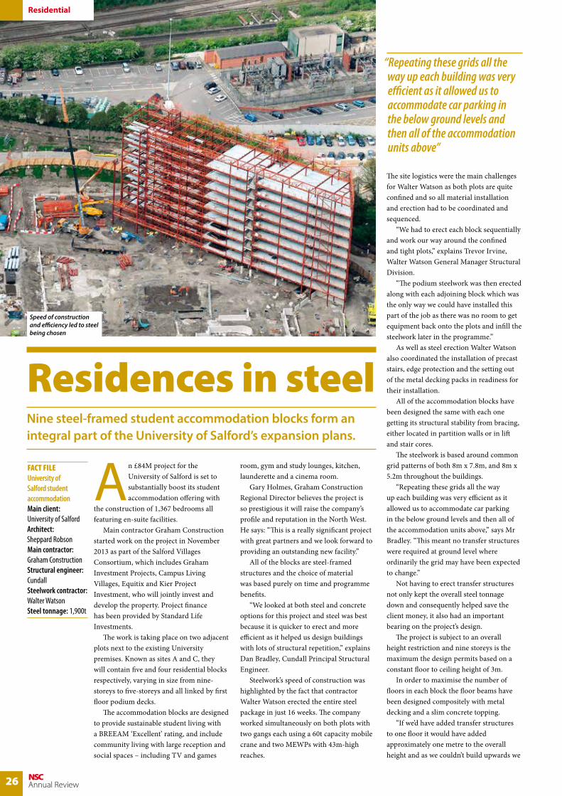
26 NSCAnnual Review
An £84M project for the University of Salford is set to substantially boost its student accommodation offering with
the construction of 1,367 bedrooms all featuring en-suite facilities. Main contractor Graham Construction started work on the project in November 2013 as part of the Salford Villages Consortium, which includes Graham Investment Projects, Campus Living Villages, Equitix and Kier Project Investment, who will jointly invest and develop the property. Project finance has been provided by Standard Life Investments. The work is taking place on two adjacent plots next to the existing University premises. Known as sites A and C, they will contain five and four residential blocks respectively, varying in size from nine-storeys to five-storeys and all linked by first floor podium decks. The accommodation blocks are designed to provide sustainable student living with a BREEAM ‘Excellent’ rating, and include community living with large reception and social spaces – including TV and games
room, gym and study lounges, kitchen, launderette and a cinema room. Gary Holmes, Graham Construction Regional Director believes the project is so prestigious it will raise the company’s profile and reputation in the North West. He says: “This is a really significant project with great partners and we look forward to providing an outstanding new facility.” All of the blocks are steel-framed structures and the choice of material was based purely on time and programme benefits. “We looked at both steel and concrete options for this project and steel was best because it is quicker to erect and more efficient as it helped us design buildings with lots of structural repetition,” explains Dan Bradley, Cundall Principal Structural Engineer. Steelwork’s speed of construction was highlighted by the fact that contractor Walter Watson erected the entire steel package in just 16 weeks. The company worked simultaneously on both plots with two gangs each using a 60t capacity mobile crane and two MEWPs with 43m-high reaches.
The site logistics were the main challenges for Walter Watson as both plots are quite confined and so all material installation and erection had to be coordinated and sequenced. “We had to erect each block sequentially and work our way around the confined and tight plots,” explains Trevor Irvine, Walter Watson General Manager Structural Division. “The podium steelwork was then erected along with each adjoining block which was the only way we could have installed this part of the job as there was no room to get equipment back onto the plots and infill the steelwork later in the programme.” As well as steel erection Walter Watson also coordinated the installation of precast stairs, edge protection and the setting out of the metal decking packs in readiness for their installation. All of the accommodation blocks have been designed the same with each one getting its structural stability from bracing, either located in partition walls or in lift and stair cores. The steelwork is based around common grid patterns of both 8m x 7.8m, and 8m x 5.2m throughout the buildings. “Repeating these grids all the way up each building was very efficient as it allowed us to accommodate car parking in the below ground levels and then all of the accommodation units above,” says Mr Bradley. “This meant no transfer structures were required at ground level where ordinarily the grid may have been expected to change.” Not having to erect transfer structures not only kept the overall steel tonnage down and consequently helped save the client money, it also had an important bearing on the project’s design. The project is subject to an overall height restriction and nine storeys is the maximum the design permits based on a constant floor to ceiling height of 3m. In order to maximise the number of floors in each block the floor beams have been designed compositely with metal decking and a slim concrete topping. “If we’d have added transfer structures to one floor it would have added approximately one metre to the overall height and as we couldn’t build upwards we
Residential
Residences in steelNine steel-framed student accommodation blocks form an integral part of the University of Salford’s expansion plans.
FACT FILEUniversity of Salford student accommodationMain client: University of SalfordArchitect: Sheppard RobsonMain contractor: Graham ConstructionStructural engineer: CundallSteelwork contractor: Walter Watson Steel tonnage: 1,900t
“Repeating these grids all the way up each building was very efficient as it allowed us to accommodate car parking in the below ground levels and then all of the accommodation units above”
Speed of construction and efficiency led to steel being chosen
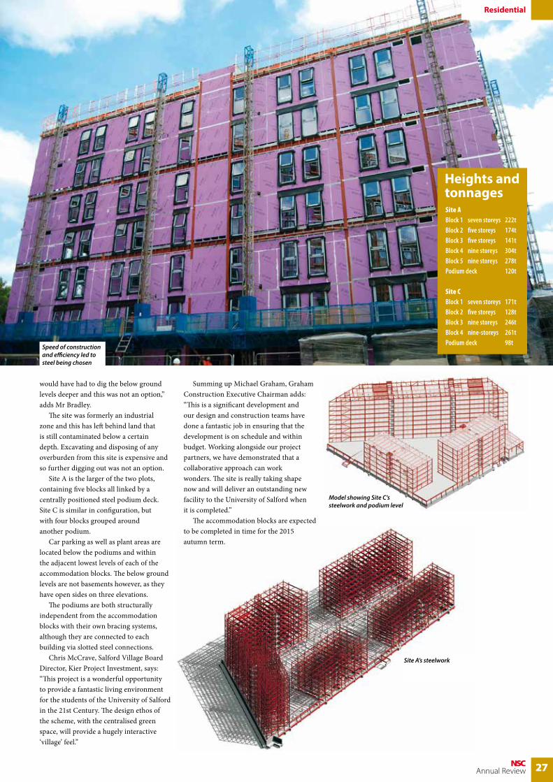
27NSCAnnual Review
Residential
Site ABlock 1 seven storeys 222tBlock 2 five storeys 174tBlock 3 five storeys 141tBlock 4 nine storeys 304tBlock 5 nine storeys 278tPodium deck 120t
Site CBlock 1 seven storeys 171tBlock 2 five storeys 128tBlock 3 nine storeys 246tBlock 4 nine-storeys 261tPodium deck 98t
Heights and tonnages
Site A’s steelwork
Model showing Site C’s steelwork and podium level
would have had to dig the below ground levels deeper and this was not an option,” adds Mr Bradley. The site was formerly an industrial zone and this has left behind land that is still contaminated below a certain depth. Excavating and disposing of any overburden from this site is expensive and so further digging out was not an option. Site A is the larger of the two plots, containing five blocks all linked by a centrally positioned steel podium deck. Site C is similar in configuration, but with four blocks grouped around another podium. Car parking as well as plant areas are located below the podiums and within the adjacent lowest levels of each of the accommodation blocks. The below ground levels are not basements however, as they have open sides on three elevations. The podiums are both structurally independent from the accommodation blocks with their own bracing systems, although they are connected to each building via slotted steel connections. Chris McCrave, Salford Village Board Director, Kier Project Investment, says: “This project is a wonderful opportunity to provide a fantastic living environment for the students of the University of Salford in the 21st Century. The design ethos of the scheme, with the centralised green space, will provide a hugely interactive ‘village’ feel.”
Summing up Michael Graham, Graham Construction Executive Chairman adds: “This is a significant development and our design and construction teams have done a fantastic job in ensuring that the development is on schedule and within budget. Working alongside our project partners, we have demonstrated that a collaborative approach can work wonders. The site is really taking shape now and will deliver an outstanding new facility to the University of Salford when it is completed.” The accommodation blocks are expected to be completed in time for the 2015 autumn term.
Speed of construction and efficiency led to steel being chosen

28 NSCAnnual Review
Embodied Carbon
Carbon calculation explained Efforts to reduce operational carbon in buildings through improved legislation means that embodied carbon is increasingly important.
Ambitious targets have been set by the Government to reduce greenhouse gas emissions and, as the operation of buildings
currently accounts for nearly half of these, a significant improvement in new and existing building performance is required. This is being driven by changes to Approved Document L, with an ambition to have all new buildings zero carbon in operation by 2019. This means that embodied carbon emissions are likely to become more important. Embodied carbon refers to the greenhouse gas emissions that occur during the manufacture of construction products. The definition can also include any emissions that occur during the construction process itself, the operational lifetime of the building and the end of life disposal of the materials. This is sometimes referred to as the cradle to (factory) gate option, the cradle to (installation) site option, or the cradle to cradle option, the latter of which is also known often as the whole life approach. “The steel industry promotes the whole life approach to embodied carbon calculation,” says John Dowling, British Constructional Steelwork Association Sustainability Manager. “Only this cradle to cradle method will give you an holistic understanding of the lifetime impacts of
construction materials. The other methods fail to do this.” Mr Dowling goes on to say: “The strength of a cradle to gate approach to embodied carbon calculation has in the past been that information has been readily available for most materials. The quality of that data may be questionable on occasion but its saving grace is that it has been there. “The weaknesses however are significant because the cradle to gate approach assumes that all materials are more or less equal at end of life. So, recycling is deemed to be the same as landfill and a material that leaves a detrimental legacy when it comes to the end of its useful life is considered to be the same as one that leaves a positive impact. “The strength of a cradle to cradle approach is that it does not assume that all end of life outcomes are equal and that positive outcomes at end of life, such as recycling are rewarded and negative outcomes, such as landfill, are penalised. In the past, the weakness of this approach has been a lack of whole life data, but that has now been remedied. The steel, concrete and timber industries have all put their houses in order and produced good, reliable end of life data.” To help the construction industry navigate its way through the process of embodied carbon calculation, Tata Steel and the British Constructional Steelwork Association have published a guide on the
Manufacture
Extraction
Cradleto
Gate
Transport
ConstructionDemolition
Recycling
Manufacture
Extraction
Cradleto
Cradle
Transport
ConstructionDemolition
Recycling
Test showed that less carbon was produced as a result of the decision to use a steel frame on One Kingdom Street in London

29NSCAnnual Review
Embodied Carbon
Product BS EN15804 Modules
Total(kgCO2e/kg)
A1-A3(kgCO2e/kg)
C1-C4(kgCO2e/kg)
D(kgCO2e/kg)
Brickwork 0.16 0.01 -0.0207 0.15
Concrete blockwork 0.09 0.0103 -0.0053 0.10
C40 concrete 0.13 0.0043 -0.0053 0.13
C50 concrete 0.17 0.0037 -0.0053 0.17
Lightweight C40 concrete 0.17 0.0111 -0.0053 0.18
Hollowcore slab 0.2 0.0006 -0.0103 0.19
Hot rolled plate and structural sections 1 1.735 0.06 -0.959 0.84
Hot formed structural hollow sections 1 2.49 0.06 -1.38 1.17
Reinforcing steel 1 1.27 0.061 -0.426 0.91
Steel deck 2.52 0.06 -1.45 1.131 Fabrication (bending, cutting and welding for rebar) impacts have not been included.
Aweb tool that enables designers of multi-storey buildings to easily
estimate the embodied carbon footprint of the superstructure has been developed and is available for download at www.steelconstruction.info/Design_software_and_tools Designers can use the tool in two ways. In ‘auto-generate’ mode, the basic building geometry, structural grid and chosen floor system are used to estimate structural material quantities using algorithms developed by the Steel ConstructionInstitute (SCI). Alternatively, a user may use the ‘manual input’ mode to enter the actual material quantities for the building. To compare the impact of a steel framed building with a concrete framed building; the web tool should be run separately for each building.
Help for multi-storey designers
BS EN 15804 provides rules to assist with the consistent calculation of embodied carbon, and divides the lifetime of a construction product into modules: A, B,C & D, some of which are further sub-divided. So for example, modules A1-A3 cover the production stage (cradle to gate) and modules A4-A5 cover the construction stage. For most construction products, A4-A5 are relatively small and are often ignored. The B modules cover the operational stage of the lifecycle, but these are also generally small and are ignored. Modules C1-C4 cover the demolition, separation and removal processes, and module D takes account of the positive or negative impacts of recycling, reuse or disposal to landfill. Adding these together as shown gives a cradle to cradle total.
subject, the latest in their series of steel construction guidance publications. A must read for the entire construction industry, the guide explains what embodied carbon is and how it impacts on the total emissions of a building throughout its lifecycle. The guide gives designers an overview of how
embodied carbon should be considered and calculated, some practical guidance on how to assess it on individual projects, and the significance of end of life impacts, while some case studies show how structural steelwork compares with other framing materials. The guide is available for download at www.steelconstruction.info/Steel_construction_news
St James’s Market in London, the multi-million pound redevelopment scheme underway just south of Piccadilly Circus will deliver 24,100m2 of commercial and retail space between Regent Street and Haymarket
Embodied Carbon Data

30 NSCAnnual Review
Cost
Frame costs assessment made simpleNew guidance from the steel construction sector used with regularly updated cost data makes potentially tricky exercises in cost planning straightforward.
Steel is by a large margin the most popular framing material for most building types in the UK – around 70% of multi-storey
buildings and over 90% of single storey industrial buildings are steel framed. Along with a wide range of benefits affecting sustainability, flexibility in use and future proofing, steel delivers significant cost advantages compared to alternative materials. For a start, the lower self weight of steel ensures a lighter structure that demands smaller and cheaper foundations. There are a multitude of programme and other advantages to be gained from using off site fabricated steel, many impacting directly on the bottom line, which the steel construction sector is dedicated to ensuring that designers, contractors and their clients fully appreciate how to take advantage of. Properly costing the alternative framing solutions at the early planning stages can be a tricky exercise but the steel sector produces regularly updated guidance on the cost planning process
Realistic cost information
Realistic cost information has to be provided very early in the construction planning process to support decisions
on what structural frame materials to use. These decisions are very difficult to change later as this could lead to delay in the construction programme, partly due to impacting the design of other building elements like foundations, finishes and cladding. A wrong decision can lead to higher costs than necessary for the frame and other elements. The guide leads planners through the process of choosing the frame material and configuration of a project, key early decisions that are usually based on initial outline information and comparative budget costings. Cost models and benchmarks are key tools at these early stages and cost consultants need to develop a thorough understanding of both the project and the historic cost data
BCIS rates for different locationsas of 3/10/2014 (UK Mean = 100)
Location BCIS Index
City of London 112
Glasgow 99
Cardiff 98
Birmingham 96
Nottingham 94
Manchester 92
Newcastle 92
Leeds 91
Liverpool 87
Belfast 63
used so they can adapt standard cost ranges to suit a specific project. A range of key cost drivers will have to be considered including building function, sector, location and site constraints, as well as current market conditions and the proposed procurement route. The guide explains that when undertaking cost analyses of alternative structural options or systems, it is important not to review frame costs in isolation, but to also consider the impact that frame choice has on related building elements, such as substructure, cladding and M&E installations, to allow proper comparative costings. Once a design has been developed, the initial budget will be tested against the emerging design of the actual building through a quantification of the key components. At this stage, the key cost drivers considered during early estimates, such as function and site constraints, will be reflected in the designs
used for cost planning. Other factors such as section sizes and availability, connections, fire protection requirements and construction methodology also have to be considered to ensure that an appropriate rate per tonne of steel is selected. Consideration of these key factors throughout the design stages along with early consultation with the supply chain can help make sure that realistic costing of the steel frame and associated elements is maintained and improved as the design develops. The guide provides a study of two typical buildings – a business park office building and a city centre office building – to provide a comparison for reference when considering the structural frame options. These studies are made by independent teams from G&T, Peter Brett Associates and Mace Group – to reflect changes in construction techniques and structural frame solutions since earlier studies.
itself as well as updates on real world prices for structural steelwork.
The cost planning process guidance, from Tata Steel and the BCSA, can be downloaded free from the website

31NSCAnnual Review
Cost
Building 1 rates at Q3 2014 on GIFA basis (City of London BCIS Location)
Steel composite
Steel + Precast Concrete Slabs
Reinforced Concrete Flat Slab
Post-tensioned Concrete Flat Slab
Substructure £56/m2 £60/m2 £72/m2 £67/m2
Frame and Upper Floors £150/m2 £164/m2 £157/m2 £162/m2
Total Building £1613/m2 £1643/m2 £1716/m2 £1696/m2
Building 2 rates at Q3 2014 on GIFA basis (City of London BCIS Location)
Steel Cellular Composite Post-tensioned Concrete Band Beam and Flat Slab
Substructure £60/m2 £64/m2
Frame and Upper Floors £208/m2 £228/m2
Total Building £1958/m2 £2026/m2
Benchmark rates at Q3 2014 on GIFA basis
Type BCIS Index 100 City of London
Frame
Low rise, short spans, repetitive grid/sections, easy-access (Building 1) £80-108/m2 £95-130/m2
High rise, long spans, easy-access, repetitive grid (Building 2) £134-160/m2 £149-180/m2
High rise, long spans, complex access, irregular grid, complex elements £154-180/m2 £175-200/m2
Floor
Metal decking and lightweight concrete topping £43-61/m2 £50-70/m2
Precast concrete floor and topping £48-65/m2 £55-75/m2
Fire protection (60 min resistance) £7-16/m2 £9-18/m2
Portal frames
Low eaves (6-8m) £48-70/m2 £58-80/m2
High eaves (10-13m) £58-80/m2 £70-96/m2
Arange of factors affect initial cost estimates, including the building’s function and facilities, location and site
constraints, market conditions and procurement route, and the guide explains their potential impact on proper assessment of costs for structural steel frames. For example, for analysing the impact of location and site constraints on cost estimates the use of the most commonly used guide to cost indices for different locations – the Building Cost Information Service (BCIS) from the Royal Institute of Chartered Surveyors – is explained. The importance of adjusting the rate for the proposed location to make sure that the different local market conditions are taken into account is highlighted – using a City of London benchmarked rate (BCIS index 112) for a new project in Cardiff (BCIS index 98) would
significantly affect the accuracy of the estimate. The site itself also has a direct impact on the proposed building’s design and cost. For instance, it may affect the floor plate configuration, building height and the regularity of the structural grid. A regular, repeating grid is the most cost efficient option, and if non-standard sections or a wide range of different sections and connections are needed, the project will be more complex and therefore more expensive as fabrication costs will be higher. Some buildings have specialised requirements, such as retaining a historic façade, close neighbours or poor ground conditions to overcome. If these require complex structural solutions such as transfer structures and heavy fabricated beams, the bespoke fabrication costs will push up the overall cost and may also add to installation time and cost.
Location and site constraints
www.steelconstruction.info. It is based on regular research by cost consultants Gardiner & Theobald (G&T) into key aspects of structural steelwork design and construction for the Steel Insight cost studies series which is also available free at www.steelconstruction.info Following the procedures in the guide provides clarity for cost planners through the various stages involved in pricing structural steelwork. All the key factors that need to be taken into account are highlighted, from initial design stages through option analysis and on to detailed design. The aim throughout is to show how a sometimes complex calculation can actually be made straightforward. Assembling the relevant information at each stage in the process is fundamental to achieving optimal solutions, and the guide shows how to do this properly, ensuring that the correct information is sourced. The guide is designed to be used in conjunction with the information detailed in the Steel Insight series which helps cost planners get over the problems that can arise in trying to get accurate cost information in fast changing markets, providing regular quarterly updates on steel construction costs from G&T. Each of the detailed articles in the Steel Insight series includes an update of standard cost tables to help cost planners. Other free assistance provided recently by the steel sector to help cost planners and designers in assessing their options include guides on Embodied Carbon, Thermal Mass and Fire Protection. All of these and other up to date information on issues like using Building Information Modelling, and on the acoustic and vibration performance of steel, can also be found at www.steelconstruction.info
Building 1
Building 2

32 NSCAnnual Review
Thermal Mass
Utilising thermal massThermal mass within a steel frame can reduce a structure’s CO2 emissions while also contributing to overall cost savings.
The majority of designers and engineers are looking to achieve the optimum thermal mass of a building to
help minimise the energy required for cooling. This can ultimately save the client a lot of money otherwise spent on powering air conditioning units. Rising energy costs and a possible increase in temperature over the next 100 years, due to climate change, have both prioritised the need to construct buildings in the most energy efficient way. Designers can make use of Thermal Mass in buildings to address this issue. Structural steelwork offers a number of benefits, such as cost efficiency and speed of construction, but using a structural steel frame can also offer the design team the perfect solution for an economic and cost effective method for achieving peak thermal mass. “It’s a common misconception that a building needs to have large volumes of concrete to achieve thermal mass. In fact the first 50-75mm of an exposed concrete soffit is the bit that does all the work – the thickness of material exceeding this is thermally neutral in its beneficial effects on the space below,” explains Edward Murphy, Mott MacDonald Technical Director. Thermal mass is the ability of a structure’s interior to absorb excess heat. The element with the most thermal mass is the concrete in the floor slab and for this to work efficiently it requires the floor soffit to be exposed. During the day, solar gain, electrical equipment as well as human activity generate heat, which warms the air in a building. Most structures would use air conditioning to artificially cool the internal environment, but if the concrete slab is exposed it can absorb and store heat during times of peak temperature, then release it later as internal temperatures fall at night. For more information visit www.steelconstruction.info/Thermal_mass or download the free publication Steel construction – Thermal mass at: www.steelconstruction.info/Steel_construction_news
During the day, solar gain, equipment use and human
activity generate heat, which warm the air in a building. The warmed air rises, flows across exposed surfaces and is absorbed into the fabric of the building. At night, cool air is allowed into the building and flows across surfaces which have been used to absorb heat during the day. These surfaces are then ready to absorb heat again the following day.
St Johns Square, Seaham – Durham CC Library
St Johns Square is a multi-use, four-storey council office block that formed part of a
£19m redevelopment of Seaham town centre. The building houses a public library and cafe as well as offices for Durham County Council and Seaham Town Council. The project team’s aim from the outset was to reduce running costs and strengthen the scheme’s sustainable credentials. The building needed to be kept cool in summer and warm in winter, sustainably. A steel framed solution, comprising metal decking and composite concrete floor slabs was decided on as the best solution, to incorporate natural ventilation and
How thermal mass works
Structure allows the free flow of air across exposed surfaces
Heat is stored in the structure by day and expelled at night by the flow of cool air across the exposed surfaces
Human activity and solar gain generate heat during the day
thermal mass to control building temperatures. Alasdair Cameron, Durham County Council Design Engineer, says: “We wanted a naturally ventilated building with a design
that would help cut down running costs and lower emissions. We also wanted to increase the thermal mass by exposing the floors to allow them to absorb heat during the day and dissipate it at night.”

33NSCAnnual Review
Website
Website is the go-to advice sourceSince being launched in 2012, www.steelconstruction.info has been enthusiastically received as it brings together in one place all the sector’s guidance and information in a single searchable location.
Specifiers and designers have been enthusiastic users of www.steelconstruction.info since it was launched, and
through 2014 the site averaged over 150,000 sessions per month. www.steelconstruction.info is the free encyclopaedia for UK steel construction, designed to be as easy to use and as comprehensive as possible – a first stop for technical guidance on steel construction. Since being launched the website has been continually improved with updated guidance being added as it becomes available. During 2014 this has included:
Improved functionality:A new magazine style PDF reader has been installed to enhance the viewing of all the features on the Steel Construction News page, a webinar facility has been added and the ‘Print PDF’ function has been upgraded to improve the layout and formatting of PDFs.
New page content:Two case studies have been added to the ‘Floor vibrations’ article, describing the dynamic modeling and assessment of floors in a school and a hospital. A further 18 fully hyperlinked project case studies have also been included. A series of Architectural student resources have been added covering: • Building design using steel• Framing schematics• Visually expressed structural forms• Expressed connections• Use of steel in cladding systems
Other new articles include ‘Steel-supported glazed façades and roofs’, ‘Façade supports and structural movements’, two fire design worked examples, and an article on ‘End of life LCA and embodied carbon data for common framing materials’, which includes a cradle-to-cradle dataset for embodied carbon.
New and updated resources:Numerous steel sector supplements published throughout 2014 in publications such as New Civil Engineer, Building Magazine, Construction News, RIBAJ, and Architecture Today have been added to the ‘Steel Construction News’ article. As have the following informative topic supplements:• Thermal mass• Cost (Update)• SSDA 2014 • Embodied carbon
An updated version of the ‘Green Book’ (SCI P358) for simple connections featuring the latest guidance on the design of gusset plates has been uploaded.
New design tools:A series of web-based design tools have been added to the ‘Design software and tools’ article:• Partial depth end plate designer• Composite beam checking tool• Elastic critical moment for lateral
torsional buckling• Fin plate designer• FireSoft – for the design of concrete filled
hollow section columns• Carbon footprint tool for buildings
New video content:The popular series of ‘Framed in Steel’ video case studies, covering notable recent steel building and bridge projects, has been expanded with the addition of:• First Direct Arena, Leeds• Derby Arena
Informative videos on How to use the Blue Book, How to use the Green Book, and how to use the website itself have been uploaded.
More CPD Content:Online CPD presentations from the series of Steel Essentials Seminars 2013, and the autumn 2013 Pricing and Cost Comparison webinars have been added, along with the
recording from the Steel Construction – Embodied Carbon webinar held in November 2014.
Updated content:Guidance on the cost of structural steelwork has been updated every quarter to reflect the latest data from Gardiner & Theobald LLP, and over 80 main pages have been reviewed and updated as part of the formal maintenance regime to ensure that information on the website remains up-to-date. www.steelconstruction.info is continuously being improved and updated to guarantee that it remains the website of choice for those interested in the steel construction sector. During 2015 new information and features will be added as and when they become available.

34 NSCAnnual Review
CE Marking
Specifying the right Execution Class
Dr David Moore explains the concept of Execution Class and provides guidance on selecting the right level of quality and assurance controls needed to ensure a structure meets the engineer’s design assumptions.
During the development of BS EN 1090-2 ‘Execution of steel structures and aluminium structures: Part 2 – Technical
requirements for the execution of steel structure’ it was decided to rationalise how the standard would deal with selecting project-specific requirements. This resulted in a Normative Annex A which groups some of the more important requirements in to four classes to facilitate a consistent selection. These classes are called ‘Execution Classes’ and are defined as ‘classified sets of requirements specified for the execution of the works as a whole, of an individual component or of a detail of a component’. BS EN 1090-2 includes an Informative
Annex B that ‘provides guidance for the choice of execution classes with respect to those execution factors that affect the overall reliability of the completed works.’
Execution class is a relatively new concept. However in recent months the constructional steelwork industry has become more aware of it, particularly, with the establishment of the Construction Products Regulation on 1st July 2013 and the introduction of the harmonised standard, BS EN 1090-1, Execution of steel structures and aluminium structures: Part 1 – Requirements for conformity assessment of structural components’ a year later on the 1st July 2014 and the mandatory CE Marking of fabricated steel and aluminium components. BS EN 1090-2 lists four execution classes which range from Execution Class 1 which gives the lowest set of requirements to Execution Class 4 which gives a higher, more stringent set of requirements. Annex B of BS EN 1090-2 gives a relationship between Consequences Class, Production Category and Service Category for determining the Execution class of a particular structure (see Table 1).
Consequences classes CC1 CC2 CC2
Service category SC1 SC2 SC1 SC2 SC1 SC2
Production categories
PC1 EXC1 EXC2 EXC2 EXC3 EXC3a EXC3a
PC2 EXC2 EXC2 EXC2 EXC3 EXC3a EXC4
a EXC4 should be applied to special structures or structures with extreme consequences of a structural failure as required by national provisions
Table 1 – Recommended matrix for determination of execution class (from BS EN 1090-2: 2008+A1: 2011)
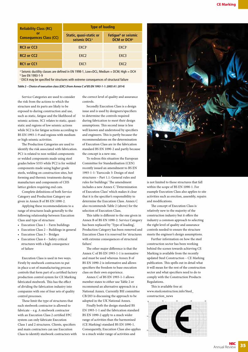
35NSCAnnual Review
CE Marking
Reliability Class (RC) orConsequences Class (CC)
Type of loading
Static, quasi-static or seismic DCLa
Fatigueb or seismic DCM or DCHa
RC3 or CC3 EXC3c EXC3c
RC2 or CC2 EXC2 EXC3
RC1 or CC1 EXC1 EXC2
a Seismic ductility classes are defined in EN 1998-1, Low=DCL; Medium = DCM; High = DCHb See EN 1993-1-9c EXC4 may be specified for structures with extreme consequences of structural failure
Service Categories are used to consider the risk from the actions to which the structure and its parts are likely to be exposed to during construction and use, such as static, fatigue and the likelihood of seismic actions. SC1 relates to static, quasi-static and regions of low seismic actions while SC2 is for fatigue actions according to BS EN 1993-1-9 and regions with medium or high seismic activities. The Production Categories are used to identify the risk associated with fabrication. PC1 is related to non welded components or welded components made using steel grades below S355 while PC2 is for welded components made using higher grade steels, welding on construction sites, hot forming and thermic treatments during manufacture and components of CHS lattice girders requiring end cuts. Complete definitions of both Service Category and Production Category are given in Annex B of BS EN 1090-2. Applying these recommendations to a range of structures leads generally to the following relationship between Execution Class and type of structure:• Execution Class 1 – Farm buildings• Execution Class 2 – Buildings in general • Execution Class 3 – Bridges • Execution Class 4 – Safety critical
structures with a high consequence of failure
Execution Class is used in two ways. Firstly by steelwork contractors to put in place a set of manufacturing process controls that form part of a certified factory production control system for CE Marking fabricated steelwork. This has the effect of dividing the fabrication industry into companies with one of four sets of quality control processes. These limit the type of structures that each steelwork contractor is allowed to fabricate – e.g. A steelwork contractor with an Execution Class 2 certified FPC system can only fabricate Execution Class 1 and 2 structures. Clients, specifiers and main contractors can use Execution Class to identify steelwork contractors with
the correct level of quality and assurance controls. Secondly Execution Class is a design issue and is used by designers/specifiers to determine the controls required during fabrication to meet their design assumptions. This second issue is less well known and understood by specifiers and engineers. This is partly because the recommendations on the determination of Execution Class are in the fabrication standard BS EN 1090-2 and partly because the concept is a new one. To redress this situation the European Committee for Standardisation (CEN) recently issued an amendment to BS EN 1993-1-1: ‘Eurocode 3: Design of steel structures – Part 1.1: General rules and rules for buildings.’ The amendment includes a new Annex C ‘Determination of Execution Class’ which makes it clear that it is the specifier’s responsibility to determine the Execution Class. Annex C also recommends Table 2 (above) for the selection of Execution Class. This table is different to the one given in Annex B of BS EN 1090-2. Service Category has been replaced by ‘Type of loading’, Production Category has been removed and Execution Class 4 is reserved for ‘structures with extreme consequences of structural failure’. The other major difference is that the Annex C of BS EN 1993-1-1 is normative and must be used whereas Annex B of BS EN 1090-2 is informative and allows specifiers the freedom to base execution class on their own experience. Annex C of BS EN 1993-1-1 allows member states to either use Table 2 or recommend an alternative approach in a National Annex. Currently BSI committee CB/203 is discussing the approach to be adopted in the UK National Annex. Finally both the design standard BS EN 1993-1-1 and the fabrication standard BS EN 1090-2 apply to a much wider range of activities than the harmonised (CE Marking) standard BS EN 1090-1. Consequently, Execution Class also applies to a much wider range of activities and
is not limited to those structures that fall within the scope of BS EN 1090-1. For example Execution Class also applies to site activities such as erection, assembly, repairs and modifications. The concept of Execution Class is relatively new to the majority of the construction industry but it offers the industry a common approach to selecting the right level of quality and assurance controls needed to ensure the structure meets the engineer’s design assumptions. Further information on how the steel construction sector has been working behind the scenes towards achieving CE Marking is available from the recently updated Steel Construction – CE Marking publication. This spells out in detail what it will mean for the rest of the construction sector and what specifiers need to do to comply with the Construction Products Regulations. This is available free at: www.steelconstruction.info/Steel_construction_news
Table 2 – Choice of execution class (EXC) (from Annex C of BS EN 1993-1-1: 2005 A1: 2014)

Taking the gambleout of your tenderselection
How can Clients, Designers and Principal Contractors ensure that steelwork isdone safely in accordance with the CDM Regulations and CE Marking?
The answer is to rely on the British Constructional Steelwork Association(BCSA) or The Register of Qualified Steelwork Contractors Scheme forBridgeworks (RQSC), as experienced assessors have visited the companies andassessed their competence based on track record, personnel and resources.
There is no easier way of prequalifying companies than using the membershiplist of the BCSA or RQSC.
Select a steelwork contractor who has the skills to suit your project.
Ensuring steelwork contractors are competent, capable and qualified
The British Constructional Steelwork Association Ltd and The Register of Qualified Steelwork Contractors Scheme for Bridgeworks
4 Whitehall Court, Westminster, London SW1A 2ES • Tel: 020 7839 8566Email: [email protected] • Website: www.steelconstruction.org
Gamble Ad.qxp_Layout 1 04/11/2014 08:00 Page 1