anovel two-dimensional tactile slip display: design ... · anovel two-dimensional tactile slip...
TRANSCRIPT
A Novel Two-Dimensional Tactile Slip Display: Design,Kinematics and Perceptual Experiments
ROBERT J. WEBSTER, III, TODD E. MURPHY, LAWTON N. VERNER, and ALLISON M. OKAMURAJohns Hopkins University
A novel two-degree-of-freedom tactile display reproduces the sensations of sliding contact and incipient slip through the rotationof a ball positioned under the user’s fingertip. A pair of motor-driven wheels actuates the ball via contact friction. Mechanicalperformance requirements are used to define the dimensions and construction method of the device. Kinematic analysis showsthat the drive wheel angles and their contact locations with the ball must be carefully selected in order to accurately controlthe axis of rotation and speed of the ball. However, psychophysical experiments indicate that some kinematic error is tolerable;errors of up to 20◦ in slip angle and 30% of a nominal velocity may be applied without detection from an average user. Thelightweight, modular tactile display was attached to a multi-degree-of-freedom kinesthetic interface and used to display virtualenvironments with slip. Experimental results demonstrate that users complete a virtual paper manipulation task with lowerapplied forces using combined slip and force feedback in comparison with conventional force feedback alone.
Categories and Subject Descriptors: H.1.2 [Models and Principles]: User/Machine Systems—Human information processing;H.5.1 [Information Interfaces and Presentation]: Multimedia Information Systems—Artificial, augmented, and virtualrealities; H.5.2 [Information Interfaces and Presentation]: User Interfaces—Haptic I/O
General Terms: Design, Experimentation, Human factors, Performance
Additional Key Words and Phrases: Haptic interface, incipient slip, tactile display, psychophysics, virtual reality
1. INTRODUCTION
The sense of touch plays a crucial role in our perception of the world and our performance of identifica-tion, manipulation, and grasping tasks. Tactile sensations are felt through a variety of modalities. Forexample, humans often tap, rub, or envelop objects during exploration. The quality of virtual realityand teleoperated systems relies in part on accurate haptic representations of relevant objects in theenvironment. While kinesthetic force feedback is widely used in these applications, tactile sensationsare often lacking because there exist many challenges in the design and construction of accurate andtransparent tactile displays.
One tactile sensation that has proven useful in grasp force modulation is the sensation of objectsslipping across the finger, including the initial incipient slip condition. We present the design and eval-uation of a novel device for displaying sliding contact at a fingertip in two degrees of freedom (DOF).The device creates tactile slip sensations by means of an actuated ball placed under the fingertip,
Author’s address: Department of Mechanical Engineering, The Johns Hopkins University, 223 Latrobe Hall, 3400 North CharlesStreet, Baltimore, MD. 21218; email: {robert.webster,tmurphy,lverner,aokamura}@jhu.edu.This work was supported in part by NDSEG Fellowships to Robert J. Webster, III and Lawton N. Verner, and the Johns HopkinsUniversity.Permission to make digital or hard copies of part or all of this work for personal or classroom use is granted without fee providedthat copies are not made or distributed for profit or direct commercial advantage and that copies show this notice on the firstpage or initial screen of a display along with the full citation. Copyrights for components of this work owned by others than ACMmust be honored. Abstracting with credit is permitted. To copy otherwise, to republish, to post on servers, to redistribute to lists,or to use any component of this work in other works requires prior specific permission and/or a fee. Permissions may be requestedfrom Publications Dept., ACM, Inc., 1515 Broadway, New York, NY 10036 USA, fax: +1 (212) 869-0481, or [email protected]© 2005 ACM 1544-3558/05/0400-0150 $5.00
ACM Transactions on Applied Perception, Vol. 2, No. 2, April 2005, Pages 150–165.
A Novel Two-Dimensional Tactile Slip Display • 151
and can be used as a modular attachment to a multi-DOF kinesthetic (force feedback) interface.This combined slip and force feedback display enables a richer set of exploratory procedures [Klatzkyand Lederman 1990] to be performed in virtual or teleoperated environments than is possible witha kinesthetic device alone. Psychophysical experiments indicate that the performance of our deviceis sufficient for realistic haptic display. Experiments using the device in conjunction with a virtualenvironment have demonstrated improvement in user force modulation in a delicate manipulation task.The feel of the slip sensation under the fingertip has also garnered positive qualitative feedback fromusers.
We begin in Section 1.1 by outlining relevant results and systems in the literature, and proceed inSection 2 to discuss the design of the slip display. Then, in Section 3, we examine the kinematics ofthe slip display and discuss drive wheel placement considerations. Section 4 presents the results ofpsychophysical experiments designed to assess the effects of kinematic considerations and also of usingnonidealized physical components on user slip perception. Section 5 examines the results of an exper-iment demonstrating how the slip display can improve user performance in a delicate manipulationtask. Section 6 provides general conclusions and future work.
1.1 Previous Work
Given the importance of human slip sensing for manipulation and exploration, first explored in thephysiology literature by Johanson and colleagues [1984] and later by Flanagan and colleagues [1994,1995, 1997], (an overview of which can be found in Johansson [1998]), it is no surprise that there hasbeen active research in the areas of robotic slip sensing and control. Many different groups, for example,Tada et al. [2001, 2002], Melchiorri [2000], Canepa et al. [1998], Son et al. [2004], and Tremblay andCutkosky [1993], have developed tactile sensors to detect slip and incipient slip conditions at the surfaceof robot fingers. (For an overview of early work in this area, see Howe [1994].) Some of these groups havealso used slip information collected from tactile sensors, combined with computer control, to modulatethe grip force of robotic manipulators. Examples include Tremblay and Cutkosky [1993] and Melchiorri[2000]. This idea was originally proposed in Salisbury [1984], and a discussion of tactile sensing toimprove the grasp of robotic fingers can be found in Bicchi et al. [1989]. As these researchers havedemonstrated, tactile slip feedback enables a computer-controlled robot to safely handle very delicateobjects without either dropping or crushing them. However, a way to display this tactile slip feedbackto a human, in order to obtain a corresponding benefit in teleoperation or virtual environments, hasnot been available. This idea serves as the motivation for our work.
Much of the prior work on displaying tactile information to a human has focused on other sensationssuch as vibration, temperature, texture, or geometry. Of these, texture and geometry are often displayedusing haptic devices employing an array of actuated point contacts. A good overview of this can be foundin Wagner et al. [2004]. Pin arrays have been used to present sliding texture to the fingertip [Ikei et al.1997], and in Ikei and Shiratori [2002] a low-resolution pin array was attached to a kinesthetic hapticdisplay for combined force and tactile feedback. However, this device included only a few pins, with pinspacings too far apart for transparency (greater than specified by the 2-point discrimination test), asnoted by the authors. Pin arrays with a larger number of pins are difficult to use in this applicationdue to inherent difficulty constructing drive mechanisms that are small and lightweight. Probablybecause of this, Kyung et al. [2004] attached their similar 6 × 1 pin array to a 2-DOF haptic mouserather than a 3-DOF device like the PHANTOM. The authors are aware of no instances in which suchpin-array displays have been used to enhance grip force control. While it may be possible to display slipand incipient slip in this context using such devices, algorithms for doing so have yet to be developed.Any such algorithms will require careful study and validation to determine how successfully pin arraydevices are able to re-create the natural fingertip sensations associated with slip and incipient slip.
ACM Transactions on Applied Perception, Vol. 2, No. 2, April 2005.
152 • R. J. Webster, III et al.
Recent work also provides some other examples of tactile displays attached to larger kinesthetichaptic devices. Feller et al. [2004] attached a pin array a teleoperated robot for palpation experiments.The effect of a rolling ball on the fingertip was studied in Provancher et al. [2003]. In contrast tothe system we present, the ball in that system does not slide with respect to the finger, but displays amoving point contact. There is also a link between our work and studies on tactile illusions, for example,Bicchi et al. [2003]. Understanding and exploiting these effects could lead to alternative strategies forcontrolling our device.
Foundational research on understanding the surface properties and neural codes associated withslip perception at the fingertip can be found in Srinivasan et al. [1990]. In that work, it was found thatslip perception is greatly improved when the surface has barely detectable micrometer-sized features,rather than near-perfect smoothness. Birznieks and colleagues [2001] have contributed substantiallyto understanding the response of fingertip mechanoreceptors, especially with regard to the directionof stimulation. Birznieks has also analyzed the human response to unpredictable frictional changeswhen performing a two digit manipulation task [Birznieks et al. 1998]. This research provides insighton the processes and control systems within the human, with respect to slip at the fingertip, whenmanipulating objects. It provides us with intuition about how haptic slip stimulation of these structuresin teleoperated or virtual tasks may be perceived and acted upon by users.
There are a few examples of previous work on the development of devices for displaying sliding contact,but all have been 1-DOF devices. Johnson and Phillips [1998] used a 1-DOF system for administeringneuroscience experiments. Salada et al. [2002a, 2002b, 2004] developed a 1-DOF bench-top device forslip display and demonstrated that sensations can be displayed on their device with enough fidelity tomake it perceptually comparable to sliding one’s finger across a real surface. Chen and Marcus [1994]also developed a 1-DOF device for displaying sliding contact to a fingertip.
Psychophysical experiments on slip angle with respect to the fingertip as well as slip velocity havebeen performed by Salada et al. [2004]. They obtain a just noticeable difference (JND) for slip angle, aswell as Weber fractions for several slip velocities at the fingertip. In contrast, our slip angle experimentobtains an absolute threshold for slip angle detection. Rather than investigating JND of constant slipvelocity, we examine user perception of time-varying velocities by overlaying sinusoidal variations ona constant velocity signal.
2. SLIP DISPLAY DESIGN
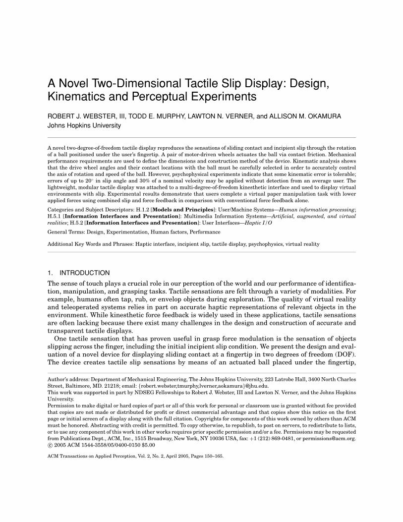
The slip display, shown in Figures 1 and 2, consists of a spherical ball supported under the user’sfingertip. The user contacts a portion of the ball through an aperture in the mechanism housing. Twoorthogonal wheels actuate the ball and create relative motion between the surface of the ball and theuser’s fingertip. The device connects to a 3-DOF PHANTOM haptic display (SensAble Technologies, Inc.)through a passive gimbal linkage. The following sections describe mechanical design specifications andconsiderations.
2.1 Specifications
To smooth integration with a kinesthetic haptic display and maximize transparency, we sought tominimize the size and weight of the device. However, there is a fundamental trade-off between minia-turization and perception of a flat sliding contact surface. As ball diameter is reduced, the contact areawith the fingertip becomes smaller and at the limit approaches a point contact. However, a larger ballrequires a proportional increase in the size and weight of the device. A 25.4 mm diameter sanded Delrinball was selected as the object to contact the finger, and the rest of the mechanism was designed aroundthis centerpiece.ACM Transactions on Applied Perception, Vol. 2, No. 2, April 2005.
A Novel Two-Dimensional Tactile Slip Display • 153
Fig. 1. The two-degree-of-freedom slip display mounted on the output link of a PHANTOM haptic device.
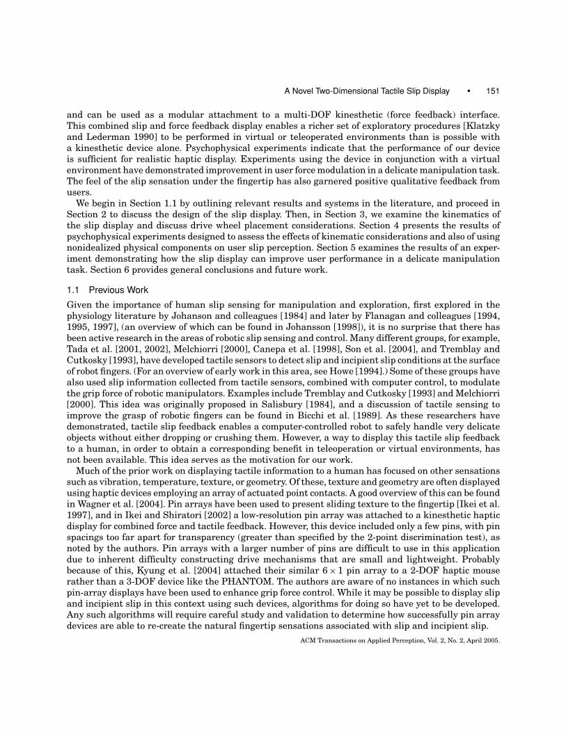
Fig. 2. An exploded view of the device assembly shows the various parts of the tactile slip display.
Determining the necessary driving torque requires an estimate of the normal force applied by a userto the ball. Qualitative experiments were conducted by pushing on a scale with a force comparable tothat used when sliding across a surface to assess its texture. These experiments resulted in a maximumnormal force estimate of 1.5 N. Another required parameter was the coefficient of friction between thefingertip and the surface of the sanded Delrin ball. Several sources (e.g., Bucholz and Frederick [1988])suggested a coefficient of µ = 0.5 as a reasonable estimate. Combining these specifications with a drivewheel diameter of 5 mm led to a torque requirement of 3.75 mNm at the drive wheels. An additionalimportant specification for motor selection was the maximum speed across the surface that the a humanis likely to use in exploration. It is reasonable to assume that typical hand speeds for users of kinesthetichaptic devices remain well under 30–40 cm/s during normal use. The research of Salada et al. suggeststhat the size of the aperture where the fingertip contacts the ball will affect user slip perception [Saladaet al. 2002a]. Using this reference and qualitative testing, a 15 mm diameter aperture was selected forthe fingertip contact interface.
ACM Transactions on Applied Perception, Vol. 2, No. 2, April 2005.

154 • R. J. Webster, III et al.
Fig. 3. (Left) The omniwheel from Murphy et al. [2004]. (Right) The drive wheel modules are spring-loaded against the ball.
2.2 Design
Two orthogonal wheels actuate the ball, which in turn imparts the slip sensation to the finger. Theball is supported by low-friction rolling contact in a special bearing developed for the slip display. Thisbearing consists of a hemispherical pocket lined with ball bearings, around the top edge of which isa bearing race. The bearing is designed to allow the steel ball bearings to roll under the large Delrinball until they reach the race, where they are pushed around the rim and returned to the area beneaththe Delrin ball. As suggested by the design of devices with a similar architecture (see Section 3), oneoptimal placement choice for each drive wheel is on the axis of rotation created by the other wheel.This arrangement minimizes the friction generated by each wheel during rotation of the other wheel.However, when both wheels turn simultaneously, this arrangement still requires that some slip occurat the wheel–ball interface. This is because these are physical wheels, and the contact with the ball isan area rather than an idealized point contact.
Our bearing design did not permit placement of the drive wheels in this particular optimal configu-ration, since the bearing supports the entire lower half of the ball. We note that one possible solutionto this is “omniwheels” (wheels that impart forces tangential to the wheel’s rim, yet present littleimpedance to motion normal to the disk of the wheel), we found in previous work that it is difficultto manufacture such wheels at this small scale [Murphy et al. 2004]. Consequently, the final designincorporates drive wheels that are solid cylinders with rubber O-rings stretched around the perimeterto produce a high-friction contact with the ball. Section 3 discusses both the desirable and undesirableeffects of drive wheel placement and orientation in detail.
Two motors apply torque to the drive wheels through a gear train. The motors selected are capa-ble of 6.75 mNm of torque at the output shaft, and a maximum speed of 9900 rpm. Speed reductionsin the gearhead and the gear train mechanism limit the ball speed to 4.88 rev/s, corresponding toa maximum slip speed of about 39 cm/s. To account for tolerances in the assembly and to provide aconsistent normal force between the wheels and the ball, each module containing the drive wheel,gear train, and motor is hinged and loaded against the ball with a torsional spring (Figure 3). Thefingertip assembly is connected to a kinesthetic haptic device through a passive gimbal linkage thatpermits rotation around three axes while maintaining the point of finger contact at a fixed locationrelative to the kinesthetic device output link. The entire assembly weighs 192 g.
While most kinesthetic haptic devices attempt to isolate motors from the user through capstan drives,the slip display does not require this. In rendering haptic slip sensations, we are concerned mainly withvelocity rather than force feedback. Any small vibrations from the motors/gearhead transmitted tothe ball in the slip display will probably appear as either small high frequency variation in velocityfrom the desired velocity or perhaps vibration of the housing itself. Neither of these effects is readilyACM Transactions on Applied Perception, Vol. 2, No. 2, April 2005.
A Novel Two-Dimensional Tactile Slip Display • 155
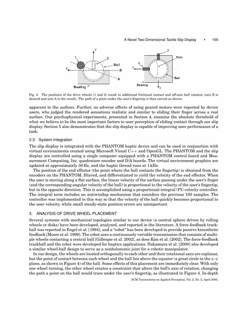
Fig. 4. The positions of the drive wheels (1 and 2) result in additional frictional contact and off-axis ball rotation (axis B isdesired and axis A is the result). The path of a point under the user’s fingertip is then curved as shown.
apparent to the authors. Further, no adverse effects of using geared motors were reported by deviceusers, who judged the rendered sensations realistic and similar to sliding their finger across a realsurface. Our psychophysical experiments, presented in Section 4, examine the absolute threshold ofwhat we believe to be the most important factors to user perception of sliding contact through our slipdisplay. Section 5 also demonstrates that the slip display is capable of improving user performance of atask.
2.3 System Integration
The slip display is integrated with the PHANTOM haptic device and can be used in conjunction withvirtual environments created using Microsoft Visual C++ and OpenGL. The PHANTOM and the slipdisplay are controlled using a single computer equipped with a PHANTOM control board and Mea-surement Computing, Inc. quadrature encoder and D/A boards. The virtual environment graphics areupdated at approximately 30 Hz, and the haptic thread runs at 1 kHz.
The position of the end effector (the point where the ball contacts the fingertip) is obtained from theencoders on the PHANTOM, filtered, and differentiated to yield the velocity of the end effector. Whenthe user is moving along a flat surface, the linear velocity of the surface passing under the user’s finger(and the corresponding angular velocity of the ball) is proportional to the velocity of the user’s fingertip,but in the opposite direction. This is accomplished using a proportional-integral (PI) velocity controller.The integral term includes an antiwindup mechanism that considers the previous 100 samples. Thecontroller was implemented in this way so that the velocity of the ball quickly becomes proportional tothe user velocity, while small steady-state position errors are unimportant.
3. ANALYSIS OF DRIVE WHEEL PLACEMENT
Several systems with mechanical topologies similar to our device (a central sphere driven by rollingwheels or disks) have been developed, analyzed, and reported in the literature. A force-feedback track-ball was reported in Engel et al. [1994], and a “cobot” has been developed to provide passive kinestheticfeedback [Moore et al. 1999]. The cobot uses a continuously variable transmission that consists of multi-ple wheels contacting a central ball [Gillespie et al. 2002], as does Kim et al. [2002]. The force-feedbacktrackball and the cobot were developed for haptics applications. Nakamura et al. [2000] also developeda similar wheel-ball design to serve as a nonholonomic joint for a robotic manipulator.
In our design, the wheels are located orthogonally to each other and their rotational axes are coplanar,but the point of contact between each wheel and the ball lies above the equator (a great circle in the x–zplane, as shown in Figure 4) of the ball. Some effects of this placement are immediately clear. With onlyone wheel turning, the other wheel creates a constraint that alters the ball’s axis of rotation, changingthe path a point on the ball would trace under the user’s fingertip, as illustrated in Figure 4. In-depth
ACM Transactions on Applied Perception, Vol. 2, No. 2, April 2005.
156 • R. J. Webster, III et al.
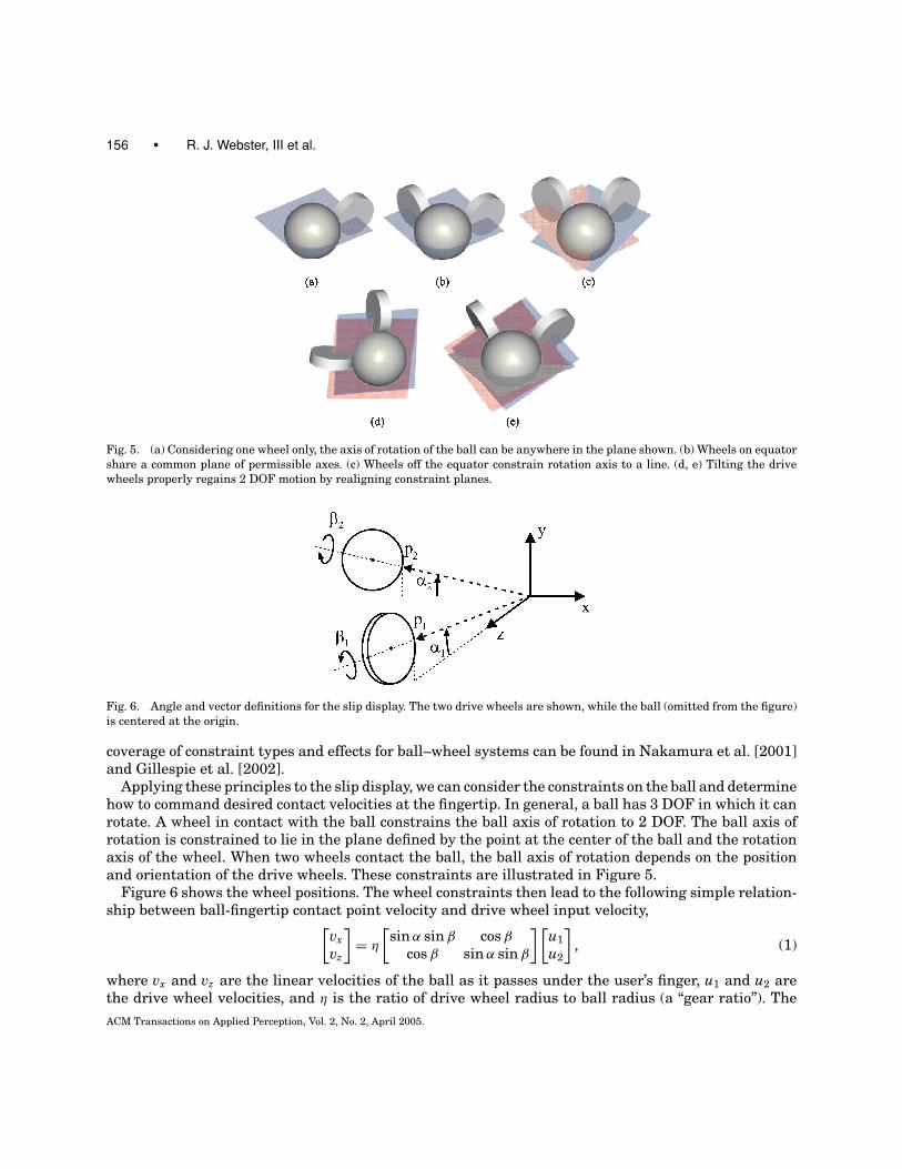
Fig. 5. (a) Considering one wheel only, the axis of rotation of the ball can be anywhere in the plane shown. (b) Wheels on equatorshare a common plane of permissible axes. (c) Wheels off the equator constrain rotation axis to a line. (d, e) Tilting the drivewheels properly regains 2 DOF motion by realigning constraint planes.
Fig. 6. Angle and vector definitions for the slip display. The two drive wheels are shown, while the ball (omitted from the figure)is centered at the origin.
coverage of constraint types and effects for ball–wheel systems can be found in Nakamura et al. [2001]and Gillespie et al. [2002].
Applying these principles to the slip display, we can consider the constraints on the ball and determinehow to command desired contact velocities at the fingertip. In general, a ball has 3 DOF in which it canrotate. A wheel in contact with the ball constrains the ball axis of rotation to 2 DOF. The ball axis ofrotation is constrained to lie in the plane defined by the point at the center of the ball and the rotationaxis of the wheel. When two wheels contact the ball, the ball axis of rotation depends on the positionand orientation of the drive wheels. These constraints are illustrated in Figure 5.
Figure 6 shows the wheel positions. The wheel constraints then lead to the following simple relation-ship between ball-fingertip contact point velocity and drive wheel input velocity,[
vxvz
]= η
[sin α sin β cos β
cos β sin α sin β
] [u1u2
], (1)
where vx and vz are the linear velocities of the ball as it passes under the user’s finger, u1 and u2 arethe drive wheel velocities, and η is the ratio of drive wheel radius to ball radius (a “gear ratio”). TheACM Transactions on Applied Perception, Vol. 2, No. 2, April 2005.
A Novel Two-Dimensional Tactile Slip Display • 157
derivation of this relationship can be found in the Appendix. Taking ω as the ball rotation axis, thederivation also yields the constraint matrix A(q) (where q = {α1, α2, β1, β2}),
A(q)ω = 0, (2)
providing a design tool to determine the proper α and β angles. The ideal relationship between α1, α2, β1,and β2 causes the constraint matrix to become one dimensional (lose rank). This provides a criterion bywhich the designer can select any two of these angles and solve for the optimal value of the remainingtwo.
We note that our device does not exactly follow this relationship because of the sub-optimal wheelangles and off-equator placement necessitated by our bearing design. Another source of error is thatphysical wheels have an area of contact with the ball rather than a point contact. This leads to kinematiccreep as described and modeled by Gillespie et al. [2002]. For the slip display as constructed, withα1 = α2 = 15◦ and β1 = β2 = 0◦, some additional slipping must occur beyond the kinematic creep ateach drive wheel for all but one axis of rotation.
While the above sources of wheel slippage error are difficult to model and analyze rigorously, thedrive wheels are still able to impart velocities in near-orthogonal directions and the path of the pointpassing under the user’s finger, as shown in Figure 4, is not curved to a large extent.
Users of the device report to us that the perceived feel of the device is similar to that of sliding theirfinger across a real surface, implying that any kinematic error is below their threshold of detection. Tomore rigorously demonstrate this, we conducted the following psychophysical experiments.
4. PSYCHOPHYSICAL EXPERIMENTS
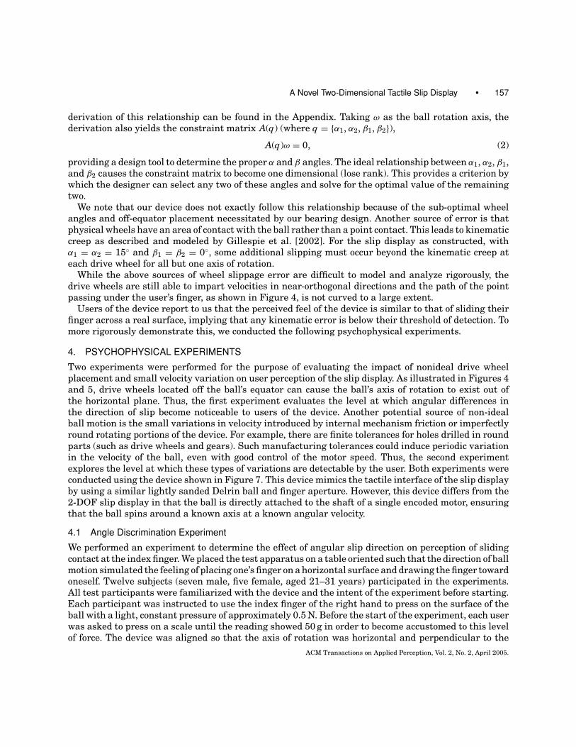
Two experiments were performed for the purpose of evaluating the impact of nonideal drive wheelplacement and small velocity variation on user perception of the slip display. As illustrated in Figures 4and 5, drive wheels located off the ball’s equator can cause the ball’s axis of rotation to exist out ofthe horizontal plane. Thus, the first experiment evaluates the level at which angular differences inthe direction of slip become noticeable to users of the device. Another potential source of non-idealball motion is the small variations in velocity introduced by internal mechanism friction or imperfectlyround rotating portions of the device. For example, there are finite tolerances for holes drilled in roundparts (such as drive wheels and gears). Such manufacturing tolerances could induce periodic variationin the velocity of the ball, even with good control of the motor speed. Thus, the second experimentexplores the level at which these types of variations are detectable by the user. Both experiments wereconducted using the device shown in Figure 7. This device mimics the tactile interface of the slip displayby using a similar lightly sanded Delrin ball and finger aperture. However, this device differs from the2-DOF slip display in that the ball is directly attached to the shaft of a single encoded motor, ensuringthat the ball spins around a known axis at a known angular velocity.
4.1 Angle Discrimination Experiment
We performed an experiment to determine the effect of angular slip direction on perception of slidingcontact at the index finger. We placed the test apparatus on a table oriented such that the direction of ballmotion simulated the feeling of placing one’s finger on a horizontal surface and drawing the finger towardoneself. Twelve subjects (seven male, five female, aged 21–31 years) participated in the experiments.All test participants were familiarized with the device and the intent of the experiment before starting.Each participant was instructed to use the index finger of the right hand to press on the surface of theball with a light, constant pressure of approximately 0.5 N. Before the start of the experiment, each userwas asked to press on a scale until the reading showed 50 g in order to become accustomed to this levelof force. The device was aligned so that the axis of rotation was horizontal and perpendicular to the
ACM Transactions on Applied Perception, Vol. 2, No. 2, April 2005.
158 • R. J. Webster, III et al.
Fig. 7. Single-axis slip device used in psychophysical experiments consisting of a 25.4 mm ball attached to the drive shaft of amotor. The user interacts with the ball in the same manner as in the 2 DOF slip display.
participant’s index finger, and the direction of slip was from the finger base to the finger tip. This wasidentified and presented to the user as the “straight” orientation. The device was then rotated 50◦
counterclockwise and each user experienced this as an example of an “angled” configuration. Userswere then blindfolded and presented with a random sequence of 10 angles ranging from 0–50◦, in 5◦
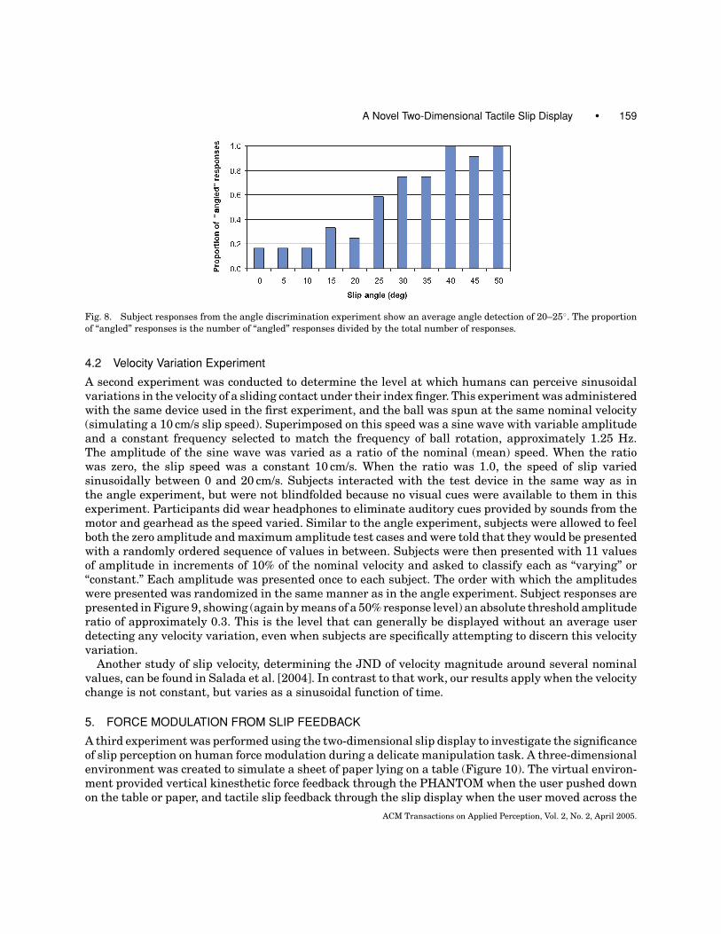
increments. During the experiment, the ball was spun at approximately 1.25 rev/s, creating a linearslip rate under the fingertip of 10 cm/s. Between presentation of each individual angle, subjects wereasked to lift their index finger off the device. Subjects were allowed to feel each angle for as long asthey liked, but were instructed not to conduct search activities such as moving their index finger inthe horizontal plane or varying contact pressure. For each angle, the subjects verbally selected either“angled” or “straight” as the best description of the sensation they were experiencing. Each anglewas presented once to each subject. The order with which the angles were presented was randomizedfor each subject (using a numerical randomization algorithm) to prevent bias. Subject responses arepresented in Figure 8. Note that the bars in this plot roughly follow the classic (s-shaped) psychometriccurve. Taking the level where 50% of subjects answered “angled” and 50% answered “straight” yieldsan absolute threshold of approximately 20◦. This indicates that the average user cannot differentiatean angled slip over the fingertip from a straight stimulus up to approximately 20◦.
It is very important to note here that this result occurs when the subject’s attention is specificallyfocused on and expecting angled slip. In cases where the subject does not know a priori that the slipdirection will be angled, we expect this absolute threshold to be even higher. If graphical visual feed-back of a straight slip direction is present, this will probably also contribute to push the thresholdstill higher. Overall, the results are encouraging for our application, because they suggest that users’perceptual experience is unlikely to be affected by small deviations in slip angle induced by the designconsiderations and nonidealized physical components that make up the device.
In experiments such as this, factors that may affect the results are the normal force applied (thereason for our training procedure with the scale) and surface texture (as noted in Srinivasan et al.[1990] and Salada et al. [2004]). In contrast to our experiment, which established an absolute thresholdfor slip angle, the angle experiment in Salada et al. [2004] determined JND of slip angle. There, userswere asked to match their perceived angle of slip to a reference angle by actively controlling the angleof slip.ACM Transactions on Applied Perception, Vol. 2, No. 2, April 2005.
A Novel Two-Dimensional Tactile Slip Display • 159
Fig. 8. Subject responses from the angle discrimination experiment show an average angle detection of 20–25◦. The proportionof “angled” responses is the number of “angled” responses divided by the total number of responses.
4.2 Velocity Variation Experiment
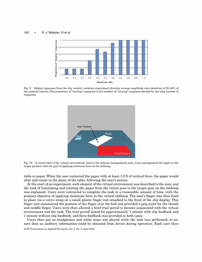
A second experiment was conducted to determine the level at which humans can perceive sinusoidalvariations in the velocity of a sliding contact under their index finger. This experiment was administeredwith the same device used in the first experiment, and the ball was spun at the same nominal velocity(simulating a 10 cm/s slip speed). Superimposed on this speed was a sine wave with variable amplitudeand a constant frequency selected to match the frequency of ball rotation, approximately 1.25 Hz.The amplitude of the sine wave was varied as a ratio of the nominal (mean) speed. When the ratiowas zero, the slip speed was a constant 10 cm/s. When the ratio was 1.0, the speed of slip variedsinusoidally between 0 and 20 cm/s. Subjects interacted with the test device in the same way as inthe angle experiment, but were not blindfolded because no visual cues were available to them in thisexperiment. Participants did wear headphones to eliminate auditory cues provided by sounds from themotor and gearhead as the speed varied. Similar to the angle experiment, subjects were allowed to feelboth the zero amplitude and maximum amplitude test cases and were told that they would be presentedwith a randomly ordered sequence of values in between. Subjects were then presented with 11 valuesof amplitude in increments of 10% of the nominal velocity and asked to classify each as “varying” or“constant.” Each amplitude was presented once to each subject. The order with which the amplitudeswere presented was randomized in the same manner as in the angle experiment. Subject responses arepresented in Figure 9, showing (again by means of a 50% response level) an absolute threshold amplituderatio of approximately 0.3. This is the level that can generally be displayed without an average userdetecting any velocity variation, even when subjects are specifically attempting to discern this velocityvariation.
Another study of slip velocity, determining the JND of velocity magnitude around several nominalvalues, can be found in Salada et al. [2004]. In contrast to that work, our results apply when the velocitychange is not constant, but varies as a sinusoidal function of time.
5. FORCE MODULATION FROM SLIP FEEDBACK
A third experiment was performed using the two-dimensional slip display to investigate the significanceof slip perception on human force modulation during a delicate manipulation task. A three-dimensionalenvironment was created to simulate a sheet of paper lying on a table (Figure 10). The virtual environ-ment provided vertical kinesthetic force feedback through the PHANTOM when the user pushed downon the table or paper, and tactile slip feedback through the slip display when the user moved across the
ACM Transactions on Applied Perception, Vol. 2, No. 2, April 2005.
160 • R. J. Webster, III et al.
Fig. 9. Subject responses from the slip velocity variation experiment showing average amplitude ratio detection of 30–40% ofthe nominal velocity. The proportion of “varying” responses is the number of “varying” responses divided by the total number ofresponses.
Fig. 10. A screen shot of the virtual environment used in the delicate manipulation task. Users manipulated the paper to thetarget position with the goal of applying minimum force to the tabletop.
table or paper. When the user contacted the paper with at least 1.5 N of vertical force, the paper wouldslide and rotate in the plane of the table, following the user’s motion.
At the start of an experiment, each element of the virtual environment was described to the user, andthe task of translating and rotating the paper from the initial pose to the target pose on the tabletopwas explained. Users were instructed to complete the task in a reasonable amount of time, with theprimary objective of applying minimum force to the virtual tabletop. The user’s finger was then fixedin place via a velcro strap on a small plastic finger rest attached to the front of the slip display. Thisfinger rest maintained the position of the finger over the ball and provided a grip point for the thumband middle finger. Users were then allowed a brief trial period to become acquainted with the virtualenvironment and the task. The trial period lasted for approximately 1 minute with slip feedback and1 minute without slip feedback, and force feedback was provided in both cases.
Users then put on headphones and white noise was played while the task was performed, to en-sure that no auditory information could be obtained from device during operation. Each user thenACM Transactions on Applied Perception, Vol. 2, No. 2, April 2005.
A Novel Two-Dimensional Tactile Slip Display • 161
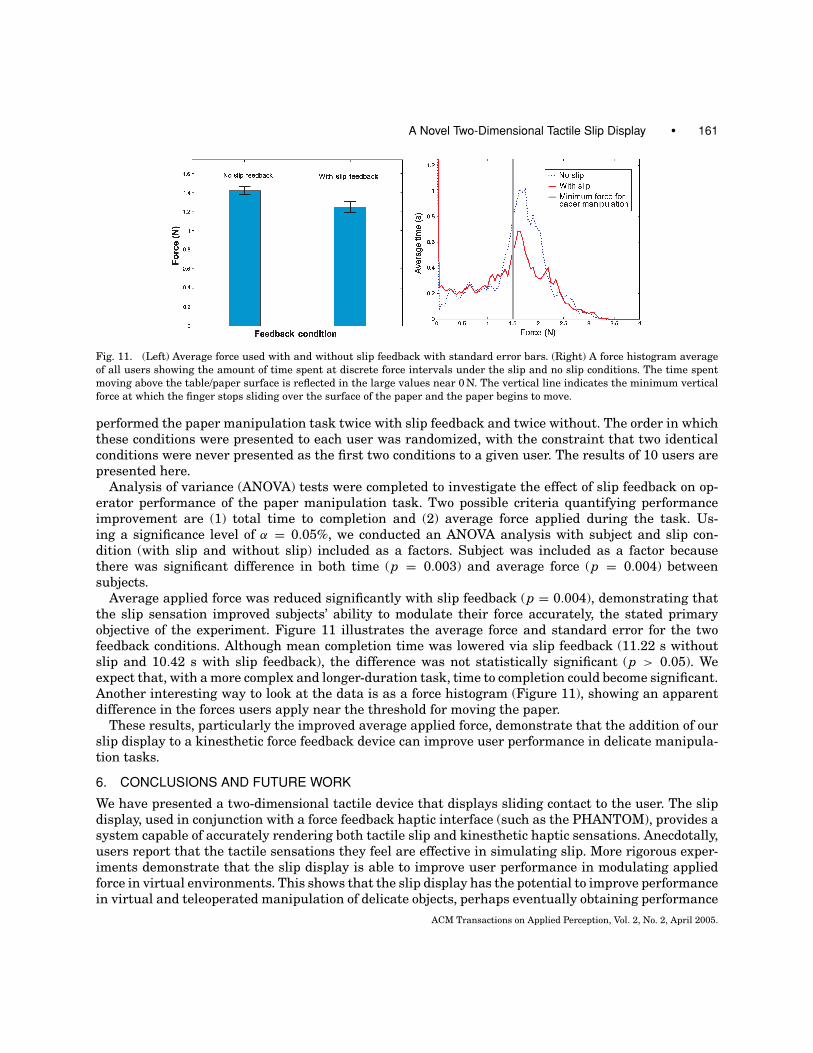
Fig. 11. (Left) Average force used with and without slip feedback with standard error bars. (Right) A force histogram averageof all users showing the amount of time spent at discrete force intervals under the slip and no slip conditions. The time spentmoving above the table/paper surface is reflected in the large values near 0 N. The vertical line indicates the minimum verticalforce at which the finger stops sliding over the surface of the paper and the paper begins to move.
performed the paper manipulation task twice with slip feedback and twice without. The order in whichthese conditions were presented to each user was randomized, with the constraint that two identicalconditions were never presented as the first two conditions to a given user. The results of 10 users arepresented here.
Analysis of variance (ANOVA) tests were completed to investigate the effect of slip feedback on op-erator performance of the paper manipulation task. Two possible criteria quantifying performanceimprovement are (1) total time to completion and (2) average force applied during the task. Us-ing a significance level of α = 0.05%, we conducted an ANOVA analysis with subject and slip con-dition (with slip and without slip) included as a factors. Subject was included as a factor becausethere was significant difference in both time (p = 0.003) and average force (p = 0.004) betweensubjects.
Average applied force was reduced significantly with slip feedback (p = 0.004), demonstrating thatthe slip sensation improved subjects’ ability to modulate their force accurately, the stated primaryobjective of the experiment. Figure 11 illustrates the average force and standard error for the twofeedback conditions. Although mean completion time was lowered via slip feedback (11.22 s withoutslip and 10.42 s with slip feedback), the difference was not statistically significant (p > 0.05). Weexpect that, with a more complex and longer-duration task, time to completion could become significant.Another interesting way to look at the data is as a force histogram (Figure 11), showing an apparentdifference in the forces users apply near the threshold for moving the paper.
These results, particularly the improved average applied force, demonstrate that the addition of ourslip display to a kinesthetic force feedback device can improve user performance in delicate manipula-tion tasks.
6. CONCLUSIONS AND FUTURE WORK
We have presented a two-dimensional tactile device that displays sliding contact to the user. The slipdisplay, used in conjunction with a force feedback haptic interface (such as the PHANTOM), provides asystem capable of accurately rendering both tactile slip and kinesthetic haptic sensations. Anecdotally,users report that the tactile sensations they feel are effective in simulating slip. More rigorous exper-iments demonstrate that the slip display is able to improve user performance in modulating appliedforce in virtual environments. This shows that the slip display has the potential to improve performancein virtual and teleoperated manipulation of delicate objects, perhaps eventually obtaining performance
ACM Transactions on Applied Perception, Vol. 2, No. 2, April 2005.
162 • R. J. Webster, III et al.
enhancements similar to those demonstrated in the literature on computer-controlled systems thatmake use of incipient slip feedback for force modulation. We also discussed in detail the design trade-offs and kinematic effects associated with wheel placement and real-world manufacturing tolerances.Psychophysical experiments assessed the effect of these factors on user perception of slip by examiningangle and velocity variation detection thresholds.
Future work on device design includes alternate placement of drive wheels as well as investigation ofmethods for encoding the motion of the ball itself, since motor encoders alone do not account for slippageof the ball relative to the wheels. The slip display also enables investigation of important questionsinvolving the nature and limits of human slip perception. In particular, the ability to decouple slip fromproprioception may allow us to explore the contribution each of these sensations to human perceptionof surface properties.
Appendix: Derivation of Wheel-Ball Velocity Relationship
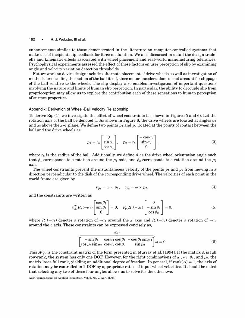
To derive Eq. (1), we investigate the effect of wheel constraints (as shown in Figures 5 and 6). Let therotation axis of the ball be denoted ω. As shown in Figure 6, the drive wheels are located at angles α1and α2 above the x–z plane. We define two points p1 and p2 located at the points of contact between theball and the drive wheels as
p1 = rb
0
sin α1cos α1
, p2 = rb
− cos α2
sin α20
, (3)
where rb is the radius of the ball. Additionally, we define β as the drive wheel orientation angle suchthat β1 corresponds to a rotation around the p1 axis, and β2 corresponds to a rotation around the p2axis.
The wheel constraints prevent the instantaneous velocity of the points p1 and p2 from moving in adirection perpendicular to the disk of the corresponding drive wheel. The velocities of each point in theworld frame are given by
vp1 = ω × p1, vp2 = ω × p2, (4)
and the constraints are written as
vTp1
Rx(−α1)
cos β1
sin β10
= 0, vT
p2Rz (−α2)
0
− sin β2cos β2
= 0, (5)
where Rx(−α1) denotes a rotation of −α1 around the x axis and Rz (−α2) denotes a rotation of −α2around the z axis. These constraints can be expressed concisely as,
A(q)︷ ︸︸ ︷[ − sin β1 cos α1 cos β1 − cos β1 sin α1cos β2 sin α2 cos α2 cos β2 sin β2
]ω = 0. (6)
This A(q) is the constraint matrix of the form presented in Murray et al. [1994]. If the matrix A is fullrow-rank, the system has only one DOF. However, for the right combinations of α1, α2, β1, and β2, thematrix loses full rank, yielding an additional degree of freedom. In general, if rank(A) = 1, the axis ofrotation may be controlled in 2 DOF by appropriate ratios of input wheel velocities. It should be notedthat selecting any two of these four angles allows us to solve for the other two.ACM Transactions on Applied Perception, Vol. 2, No. 2, April 2005.

A Novel Two-Dimensional Tactile Slip Display • 163
Deriving the velocity of a point on the ball passing underneath the user’s fingertip requires a rela-tionship that maps the drive wheel input velocities to the resulting axis of rotation of the form
ω = u1 g1 + u2 g2, (7)
where u1 and u2 are the magnitudes of the input velocities and g1 and g2 are the control vector fields.The vectors g1 and g2 must lie in the null space of A and should be selected such that they representthe velocity inputs of the two drive wheels. We define vectors d1 and d2 as the vectors passing throughpoints p1 and p2 tangent to the surface of the ball and in the direction of wheel velocity. The generalform of these vectors is
d1 = − sin β
cos α cos β
− sin α cos β
, d2 =
sin α cos β
cos α cos β
sin β
. (8)
A natural choice in our system is for g1 and g2 to point along the axis of rotation of the drive wheels,defined by
g1 = rw
rb2
[p1 × d1] = η
− cos β
− cos α sin β
sin α sin β
(9)
g2 = rw
rb2
[p2 × d2] = η
sin α sin β
cos α sin β
− cos β
(10)
where η = rw/rb. We wish to determine the linear velocity of the point p3 on the surface of the ball andin contact with the user’s fingertip. This point lies at p3 = [0 rb 0]T , and its velocity expressed in theworld coordinate frame is
v f = (u1 g1 + u2 g2) × p3. (11)
Note that the y component of v f is always zero because of the p3 contact location. Simplifying Eq. (11)yields the relationship between drive wheel input and the velocity of the point passing under the user’sfinger found in Eq. (1).
ACKNOWLEDGMENTS
The authors wish to thank Prof. Noah Cowan for judicious and mathematical review and Jake Abbottfor conceptual conversations on kinematics and control issues.
REFERENCES
BICCHI, A., SALISBURY, J. K., AND DARIO, P. 1989. Augmentation of grasp robustness using intrinsic tactile sensing. In IEEEInternational Conference on Robotics and Automation, vol. 1, 302–307.
BICCHI, A., SCILING, E. P., AND DENTE, D. 2003. Tactile flow induced haptic illusions. In Eurohaptics, Dublin, Ireland. 314–329.BIRZNIEKS, I., BURSTEDT, M. K. O., EDIN, B. B., AND JOHANSSON, R. S. 1998. Mechanisms for force adjustments to unpredictable
frictional changes at individual digits during two-fingered manipulation. Journal of Neurophysiology 80, 1989–2002.BIRZNIEKS, I., JENMALM, P., GOODWIN, A. W., AND JOHANSSON, R. S. 2001. Encoding of direction of fingertip forces by human tactile
afferents. Journal of Neuroscience 21, 20, 8222–8237.BUCHOLZ, B. AND FREDERICK, L. J. 1988. An investigation of human palmar skin friction and the effects of materials, pinch force
and moisture. Ergonomics 31, 3, 317–325.CANEPA, G., PETRIGLIANO, R., AND M. CAMPANELLA, D. D. R. 1998. Detection of incipient object slippage by skin-like sensing and
neural network processing. IEEE Transactions on Systems, Man, and Cybernetics 28, 3, 348–356.
ACM Transactions on Applied Perception, Vol. 2, No. 2, April 2005.
164 • R. J. Webster, III et al.
CHEN, E. AND MARCUS, B. 1994. Exos slip display research and development. In Proceedings of the International MechanicalEngineering Congress and Exposition. ASME DSC, vol. 55–1. 265–270.
ENGEL, F. L., GOOSSENS, P., AND HAAKMA, R. 1994. Improved efficiency through i- and e-feedback: A trackball with contextualforce feedback. International Journal of Human–Computer Studies 41, 6, 949–974.
FELLER, R. L., LAU, C. K. L., WAGNER, C. R., PERRIN, D. P., AND HOWE, R. D. 2004. The Effect of Force Feedback on RemotePalpation. In Proceedings of IEEE International Conference on Robotics and Automation. 782–788.
FLANAGAN, J. R. AND TRESILIAN, J. R. 1994. Grip load force coupling: A general control strategy for transporting objects. Journalof Experimental Psychology: Human Perception and Performance 20, 944–957.
FLANAGAN, J. R. AND WING, A. M. 1995. The stability of precision grip forces during cyclic arm movements with a hand-heldload. Experimental Brain Research 105, 455–464.
FLANAGAN, J. R. AND WING, A. M. 1997. The role of internal models in motion planning and control: Evidence from grip forceadjustments during movements of hand-held loads. Journol of Neuroscience 17, 1519–1528.
GILLESPIE, R. B., MOORE, C. A., PESHKIN, M., AND COLGATE, J. E. 2002. Kinematic creep in continuously variable transmissions:Traction drive mechanics for cobots. Journal Mechanical Design 124, 4 (Dec.), 713–722.
HOWE, R. D. 1994. Tactile sensing and control of robotic manipulation. Journal of Advanced Robotics 8, 3, 245–261.IKEI, Y. AND SHIRATORI, M. 2002. TextureExplorer: A tactile and force display for virtual textures. Haptic Interfaces for Virtual
Environment and Teleoperator Systems, 327–334.IKEI, Y., WAKAMATSU, K., AND FUKUDA, S. 1997. Texture presentation by vibratory tactile display-image based presentation of a
tactile texture. In Virtual Reality Annual International Symposium, 199–205.JOHANSSON, R. S. 1998. Sensory input and control of grip. Novartis Foundation Symposium 218, 45–59.JOHANSON, R. S. AND WESTLING, G. 1984. Roles of glabrous skin receptors and sensorimotor memory in automatic control of
precision grip when lifting rougher or more slippery objects. Experimental Brain Research 56, 550–564.JOHNSON, K. O. AND PHILLIPS, J. R. 1988. A rotating drum stimulator for scanned embossed patterns and textures across the
skin. Journal of Neuroscience Methods 22, 221–231.KIM, J., PARK, F. C., PARK, Y., AND SHIZUO, M. 2002. Design and analysis of a spherical continuously variable transmission.
ASME Journal of Mechanical Design 124.KLATZKY, R. L. AND LEDERMAN, S. J. 1990. Intelligent exploration by the human hand. In Dextrous Robot Hands, S. T. Venkatara-
man and T. Iberall, Eds. Springer-Verlag, Berlin, 66–81.KYUNG , K.-U., SON, S.-W., KWON, D.-S., AND KIM, M.-S. 2004. Design of an Integrated Tactile Display. In Proceedings of IEEE
International Conference on Robotics and Automation. 776–781.MELCHIORRI, C. 2000. Slip detection and control using tactile and force sensors. IEEE/ASME Transactions on Mechatronics 5, 3,
235–242.MOORE, C. A., PESHKIN, M. A., AND COLGATE, J. E. 1999. Design of a 3R cobot using continuously variable transmissions. In
Proceedings of IEEE International Conference on Robotics and Automation.MURPHY, T. E., WEBSTER, R. J., AND OKAMURA, A. M. 2004. Design and performance of a two-dimensional tactile slip display. In
Eurohaptics. 130–137.MURRAY, R. M., LI, Z., AND SASTRY, S. S. 1994. A mathematical introduction to robotic manipulation. In Dextrous Robot Hands,
S. T. Venkataraman and T. Iberall, Eds. CRC Press.NAKAMURA, Y., CHUNG, W., AND SRDALEN, O. 2001. Design and control of the nonholonomic manipulator. IEEE Transactions on
Robotics and Automation 17, 1.PROVANCHER, W. R., KUCHENBECKER, K. J., NIEMEYER, G., AND CUTKOSKY, M. R. 2003. Perception of curvature and object motion
via contact location feedback. In 11th International Symposium on Robotics Research, Siena, Italy.SALADA, M. A., COLGATE, J. E., LEE, M. V., AND VISHTON, P. M. 2002a. Fingertip haptics: A novel direction in hap-
tic display. In Proceedings of the 8th Mechatronics Forum International Conference. University of Twente, Enschede,Netherlands. 1211–1220.
SALADA, M. A., COLGATE, J. E., LEE, M. V., AND VISHTON, P. M. 2002b. Validating a novel approach to rendering fingertip contactsensations. In Proceedings of the 10th IEEE Virtual Reality Haptics Symposium. 217–224.
SALADA, M. A., COLGATE, J. E., VISHTON, P. M., AND FRANKEL, E. 2004. Two experiments on the perception of slip at the fingertip.In 12th Symposium on Haptic Interfaces for Virtual Environments and Teleoperator Systems. 146–153.
SALISBURY, J. K. 1984. Interpretation of contact geometries from force measurements. In Robotics Research, M. Brady andR. Paul, Eds. MIT Press, Cambridge, MA. 565–577.
SON, J. S., MONTEVERDE, E. A., AND HOWE, R. D. 2004. A tactile sensor for localizing transient events in manipulation. InProceedings of IEEE International Conference on Robotics and Automation. 471–476.
ACM Transactions on Applied Perception, Vol. 2, No. 2, April 2005.
A Novel Two-Dimensional Tactile Slip Display • 165
SRINIVASAN, M. A., WHITEHOUSE, J. M., AND LAMOTTE, R. H. 1990. Tactile detection of slip: surface microgeometry and peripheralneural codes. Journal of Neurophysiology 63, 6, 1323–1332.
TADA, M., SHIBATA, T., AND OGASAWARA, T. 2001. Artificial finger skin having ridges and distributed tactile sensors. Proceedingsof IEEE International Conference on Intellegent Robots and Systems, 686–691.
TADA, M., SHIBATA, T., AND OGASAWARA, T. 2002. Investigation of the touch processing model in human grasping based on the stickratio within a fingertip contact interface. Proceedings of IEEE International Conference on Systems, Man and Cybernetics, vol. 5.
TREMBLAY, M. R. AND CUTKOSKY, M. R. 1993. Estimating friction using incipient slip sensing during a manipulation task.Proceedings of IEEE International Conference on Robotics and Automation, 429–434.
WAGNER, C., LEDERMAN, S., AND HOWE, R. 2004. Design and performance of a tactile shape display using rc servomotors. Journalof Haptics Research 3, 4 (Aug.) (www.haptics-e.org).
Received August 2004; revised October 2004; accepted January 2005
ACM Transactions on Applied Perception, Vol. 2, No. 2, April 2005.