ansys mechanical product family - · pdf filemechanical pro mechanical premium mechanical...
TRANSCRIPT

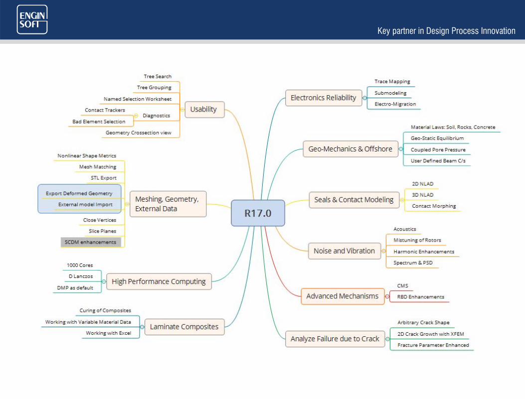
ANSYS Mechanical Product Family
Summary of Enhancements in R17.0
Corrado Meante

Revolutionary Release !
New ProductsMore than 250+ features
10x improvements in many areas

ELECTRONICS RELIABILITY
Reliability of chips and boards is not only about electronics and signal integrity. It is also about structural issues such as thermal induced deformations or migration of electrons from external forces.
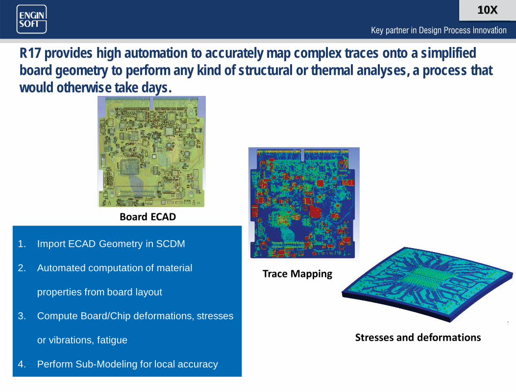
R17 provides high automation to accurately map complex traces onto a simplified board geometry to perform any kind of structural or thermal analyses, a process that would otherwise take days.
1. Import ECAD Geometry in SCDM
2. Automated computation of material
properties from board layout
3. Compute Board/Chip deformations, stresses
or vibrations, fatigue
4. Perform Sub-Modeling for local accuracy
Board ECAD
Trace Mapping
Stresses and deformations
10X
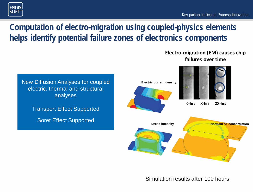
Computation of electro-migration using coupled-physics elements helps identify potential failure zones of electronics components
0-hrs X-hrs 2X-hrs
Electro-migration (EM) causes chip failures over time
New Diffusion Analyses for coupled electric, thermal and structural
analyses
Transport Effect Supported
Soret Effect SupportedStress intensity Normalized concentration
Electric current density
Simulation results after 100 hours

GEO-MECHANICS & OFFSHORE CAPABILITIES

New material laws For Geomechanics are available to simulate footings and pilings, tunneling, excavations, soil compaction or consolidation, Masonry Structures
Mohr-Coulomb
Jointed Rock
Cam-Clay
Drucker-Prager Concrete

Porous media mechanics helps simulate oil well-bore stability, tunnel excavation or biological applications such as tissues or muscles
Fluid Flow through Porous Media
Nonlinear Material laws Support
Geo-Static Equilibrium
Initial State Support
Pore-Pressure Contact Support
Anisotropic Permeability supported
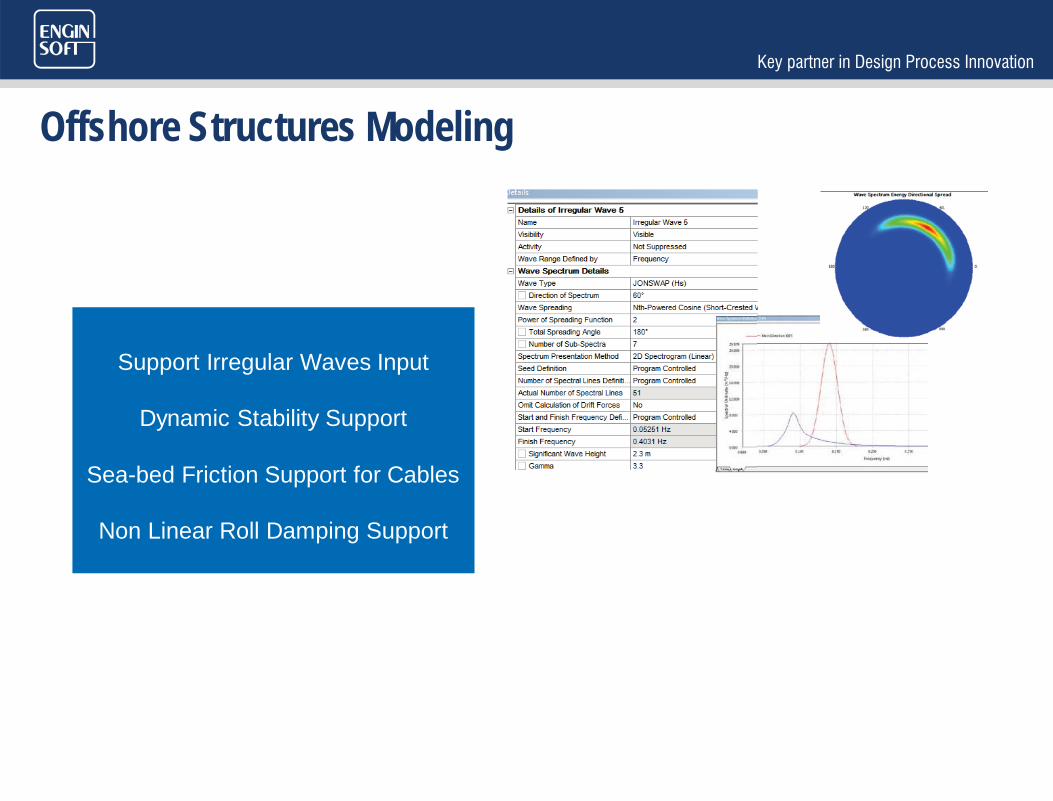
Offshore Structures Modeling
Support Irregular Waves Input
Dynamic Stability Support
Sea-bed Friction Support for Cables
Non Linear Roll Damping Support
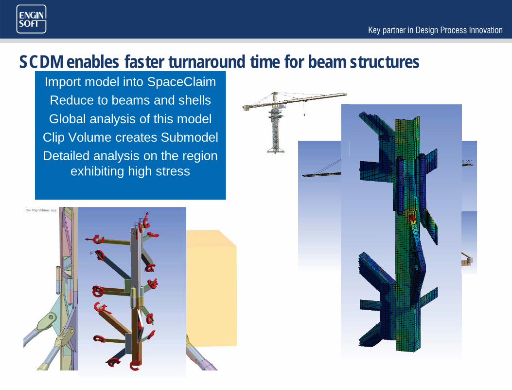
SCDM enables faster turnaround time for beam structuresImport model into SpaceClaimReduce to beams and shellsGlobal analysis of this model
Clip Volume creates SubmodelDetailed analysis on the region
exhibiting high stress

Complex Beam members can now be quickly analyzed with User Defined Beam Cross-Sections
Define C/S in DM or SCDM
Displayed as Mesh in Mechanical
Post-processing Supported

SEALS & CONTACT MODELING
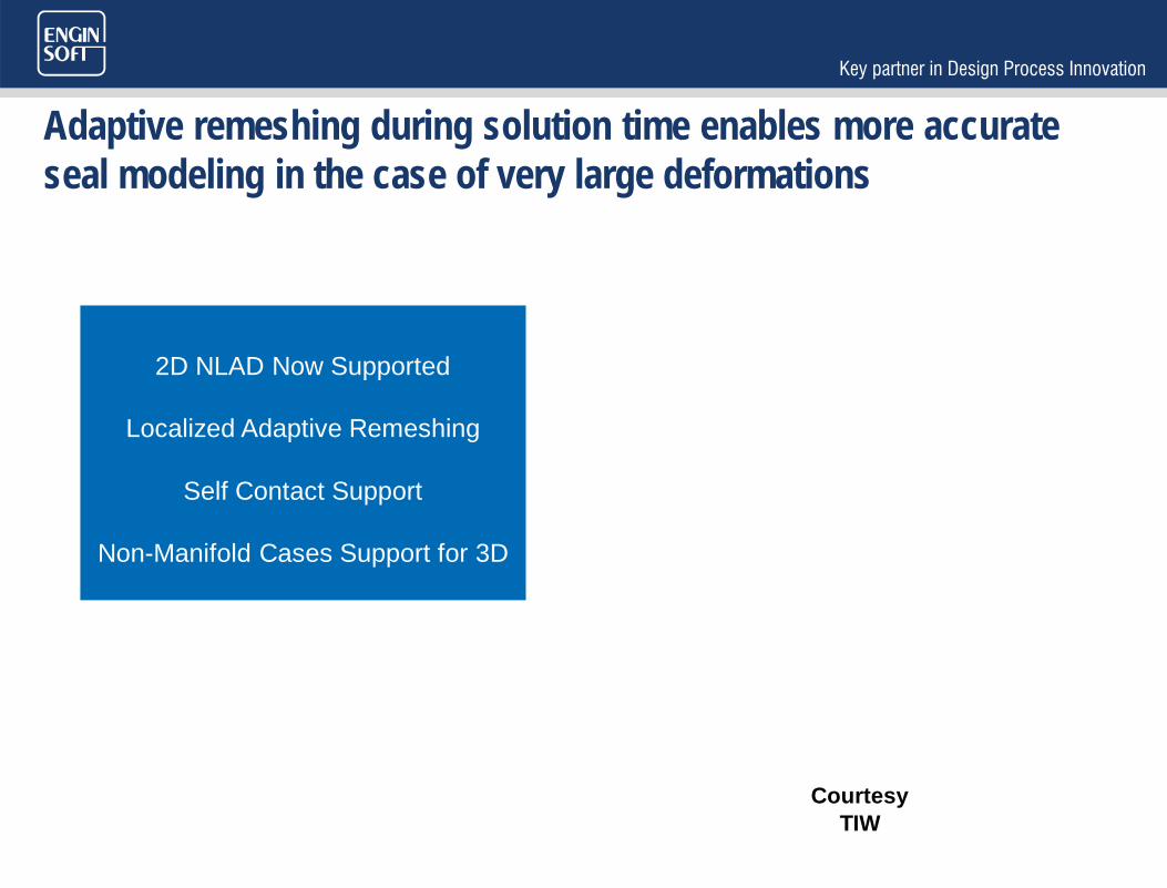
Adaptive remeshing during solution time enables more accurate seal modeling in the case of very large deformations
2D NLAD Now Supported
Localized Adaptive Remeshing
Self Contact Support
Non-Manifold Cases Support for 3D
Courtesy TIW

Adaptive meshing criterion for 2D analyses now includes element shape from maximum corner angle
In 2D analyses, Mesh criterion available in the detail view of
Nonlinear Adaptive Region
Maximum Corner Angle parameter for 2D Mesh
criterion

Initial adjustment of contact regions from morphing prevents undesired gaps and or penetration between contact surfaces to improve convergence
Mesh Morphing Approach
Close Gap and Penetration
Introduce Penetration
Stress-free mesh motion
Large gap & penetration Closed gap & penetration
Cnch, morph creating initial interference

Easy Contact definitions via General Contact Now extended to Beam-Beam
Rigid-Flex, Flex-Flex
Surface (edge)-Surface (edge), Edge-Surface, Edge-Edge

NOISE & VIBRATION

Increased exposure of harmonic analysis in Mechanical increases productivity
Cyclic Full Harmonic Available
Enforced Motion for MSUP
Frequency Dependent Loading
MSUP Harmonic supports Unlimited # of Load Steps
Full Cyclic Harmonic with Pre-
stress
Displacement Base
Excitations
Fully Frequency Dependent
Complex Loads

Spectrum & PSD Analysis is now faster and leverages parallel processing
No More Solution File Copying
Uniform Base Excitation to All Supports
RPSD Calculations Parallel
Post Enhancements
PSD Calculations
Faster
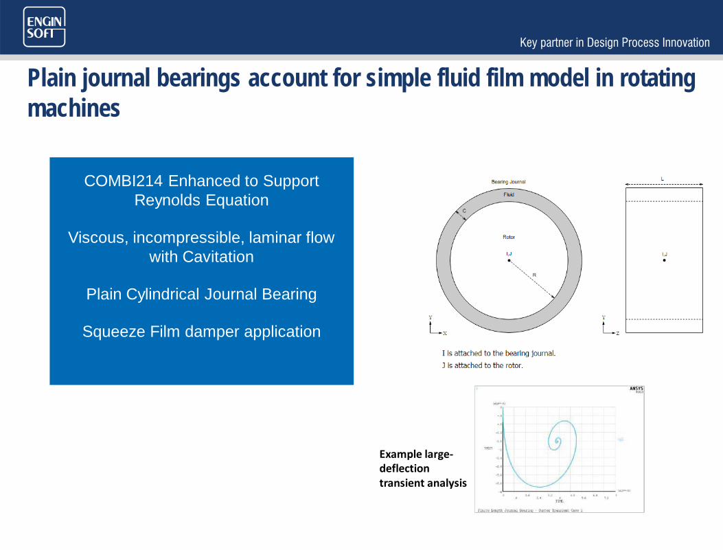
Plain journal bearings account for simple fluid film model in rotating machines
COMBI214 Enhanced to Support Reynolds Equation
Viscous, incompressible, laminar flow with Cavitation
Plain Cylindrical Journal Bearing
Squeeze Film damper application
Example large-deflection transient analysis
ADVANCED MECHANISMS MODELING
Computing rigid-flexible models with an implicit solver is time consuming. Combining explicit and implicit schemes is much faster.
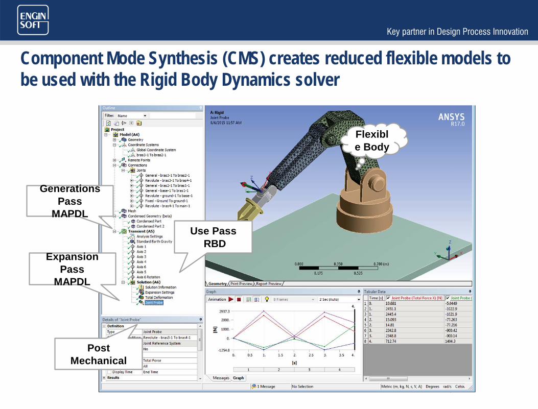
Component Mode Synthesis (CMS) creates reduced flexible models to be used with the Rigid Body Dynamics solver
Generations Pass
MAPDLUse Pass
RBDExpansion
Pass MAPDL
Post Mechanical
Flexible Body
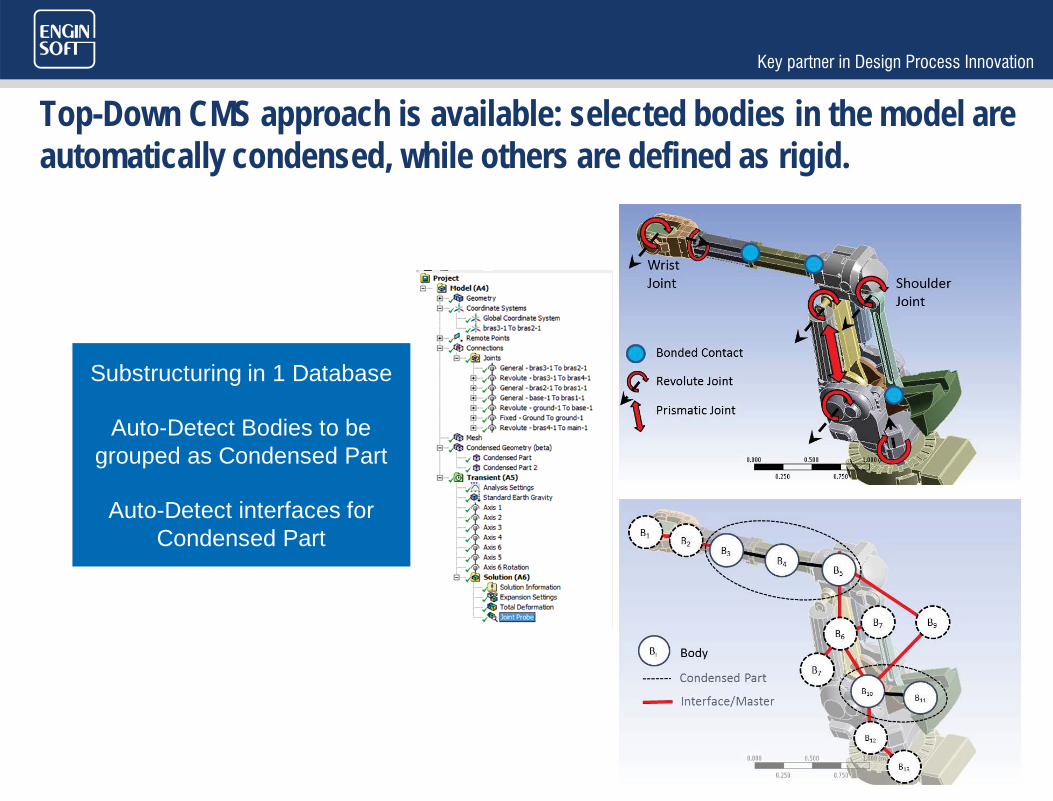
Top-Down CMS approach is available: selected bodies in the model are automatically condensed, while others are defined as rigid.
Substructuring in 1 Database
Auto-Detect Bodies to be grouped as Condensed Part
Auto-Detect interfaces for Condensed Part
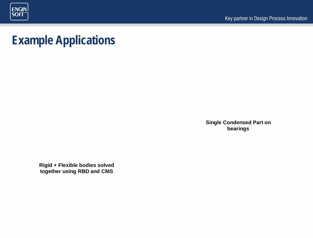
Example Applications
Rigid + Flexible bodies solved together using RBD and CMS
Single Condensed Part on bearings
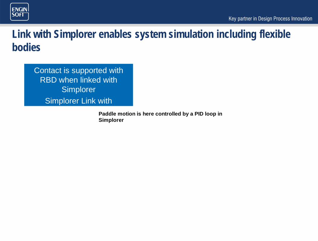
Link with Simplorer enables system simulation including flexible bodies
Contact is supported with RBD when linked with
SimplorerSimplorer Link with Assemblies having Deformable parts
Paddle motion is here controlled by a PID loop in Simplorer

ANALYZING FAILURE DUE TO CRACK
Crack geometries are in reality more complex than the typical penny-shaped cracks and are usually painful to model

R17 allows to use a surface of arbitrary shape to define a crack and automatically mesh it in seconds.
Accurately model Arbitrary Crack Surface
Planar and Non-Planar Cracks
Automatic Insertion of Crack in Base Mesh
10X Faster than Traditional methods
10X
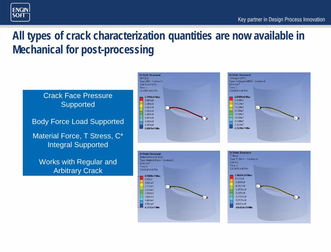
All types of crack characterization quantities are now available in Mechanical for post-processing
Crack Face Pressure Supported
Body Force Load Supported
Material Force, T Stress, C* Integral Supported
Works with Regular and Arbitrary Crack

Crack propagation is generally the results of cyclic loading on the structure, requiring to perform fatigue based computations, not available until today.
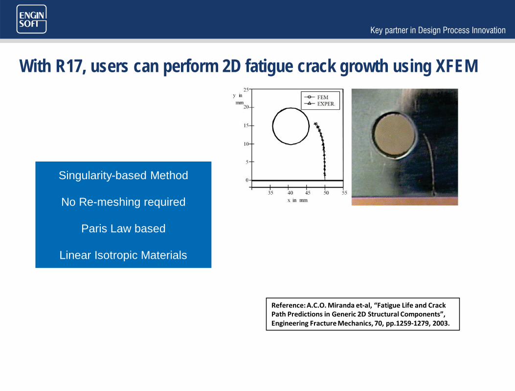
With R17, users can perform 2D fatigue crack growth using XFEM
Singularity-based Method
No Re-meshing required
Paris Law based
Linear Isotropic Materials
Reference: A.C.O. Miranda et-al, “Fatigue Life and Crack Path Predictions in Generic 2D Structural Components”, Engineering Fracture Mechanics, 70, pp.1259-1279, 2003.

LAMINATE COMPOSITES MODELING
Curing induces distortion in the final geometry of a composites model. Badly manufactured parts can induce high costs.
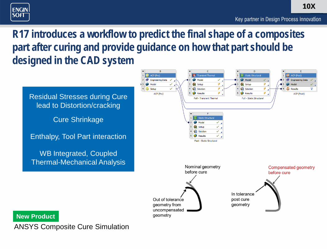
R17 introduces a workflow to predict the final shape of a composites part after curing and provide guidance on how that part should be designed in the CAD system
10X
Residual Stresses during Cure lead to Distortion/cracking
Cure Shrinkage
Enthalpy, Tool Part interaction
WB Integrated, Coupled Thermal-Mechanical Analysis
ANSYS Composite Cure SimulationNew Product
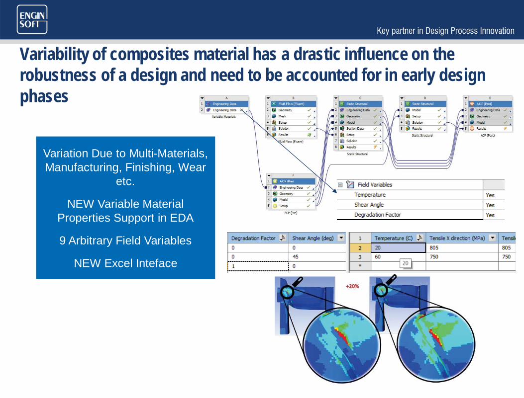
Variability of composites material has a drastic influence on the robustness of a design and need to be accounted for in early design phases
Variation Due to Multi-Materials, Manufacturing, Finishing, Wear
etc.
NEW Variable Material Properties Support in EDA
9 Arbitrary Field Variables
NEW Excel Inteface

Complex layouts of plies can be automated using interactive layup definition in EXCEL

HIGH PERFORMANCE COMPUTING

Perform dynamics analyses >10x faster with new distributed solution
NEW Distributed Bock Lanczos Solver
PSD/Spectrum Analyses Fully Parallelized
Entire Linear Dynamics Workflow now fully
parallelized
10X
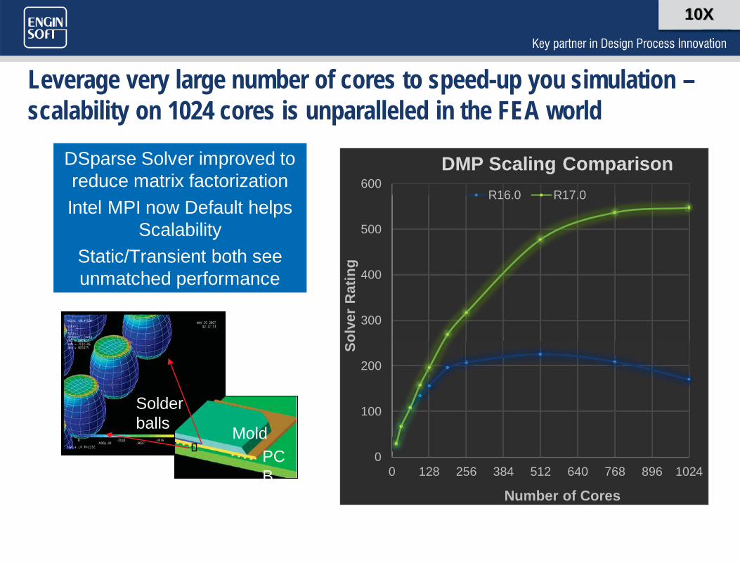
Leverage very large number of cores to speed-up you simulation –scalability on 1024 cores is unparalleled in the FEA world
DSparse Solver improved to reduce matrix factorizationIntel MPI now Default helps
ScalabilityStatic/Transient both see unmatched performance
MoldPCB
Solder balls
10X
0
100
200
300
400
500
600
0 128 256 384 512 640 768 896 1024
Solv
er R
atin
g
Number of Cores
DMP Scaling ComparisonR16.0 R17.0
MESHING, GEOMETRY, EXTERNAL MODEL
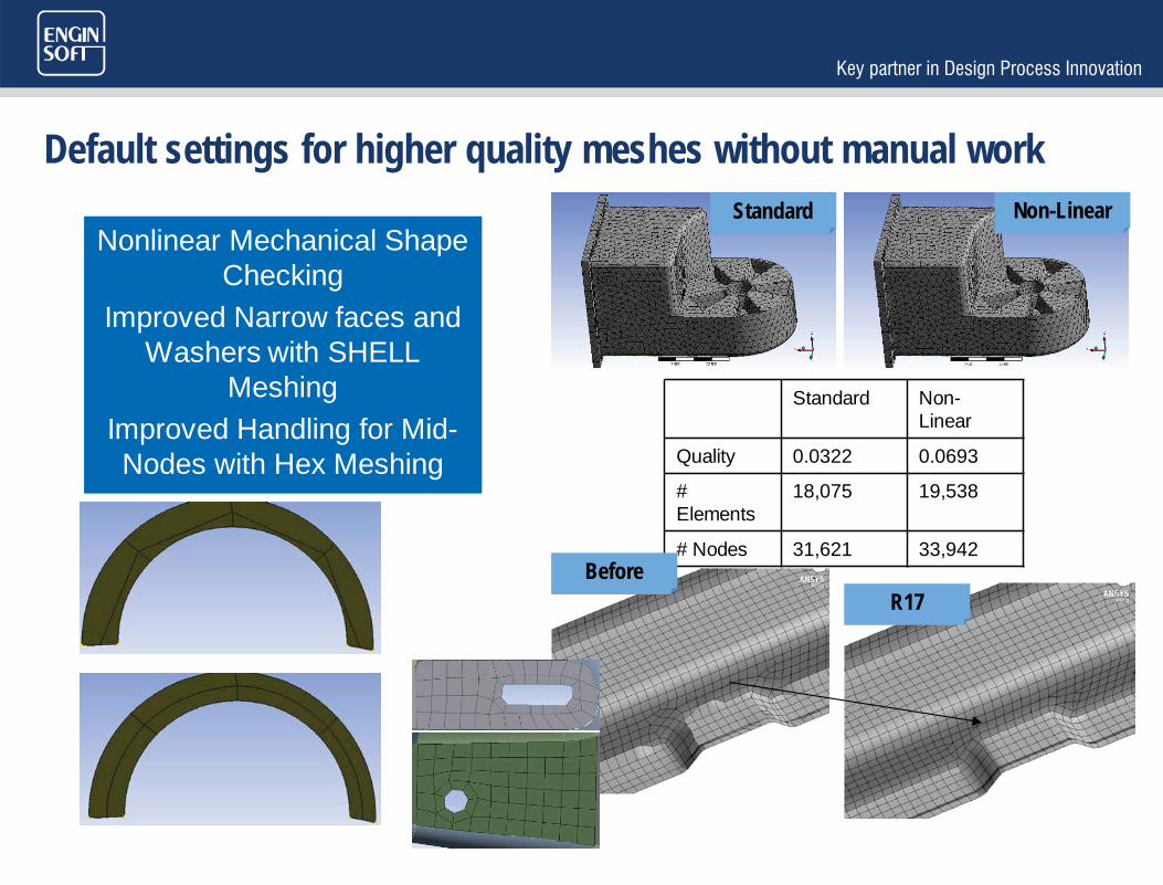
Default settings for higher quality meshes without manual work
Nonlinear Mechanical Shape Checking
Improved Narrow faces and Washers with SHELL
MeshingImproved Handling for Mid-Nodes with Hex Meshing
Standard Non-Linear
Quality 0.0322 0.0693
#Elements
18,075 19,538
# Nodes 31,621 33,942
Standard Non-Linear
BeforeR17
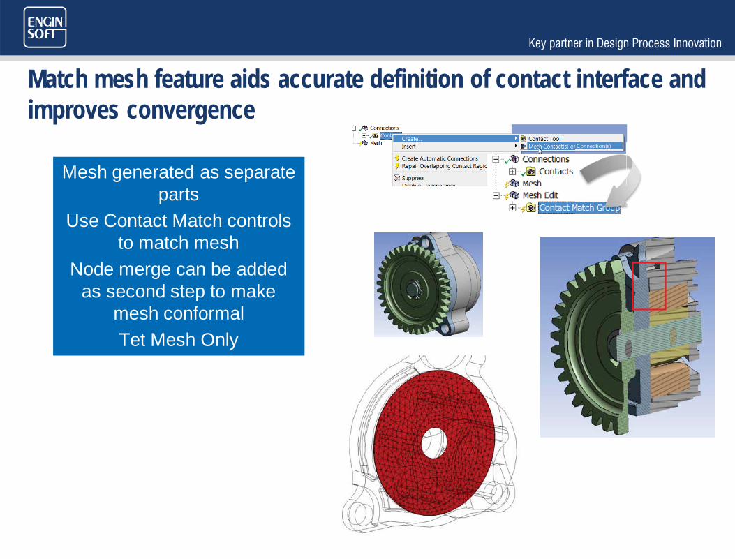
Match mesh feature aids accurate definition of contact interface and improves convergence
Mesh generated as separate parts
Use Contact Match controls to match mesh
Node merge can be added as second step to make
mesh conformalTet Mesh Only
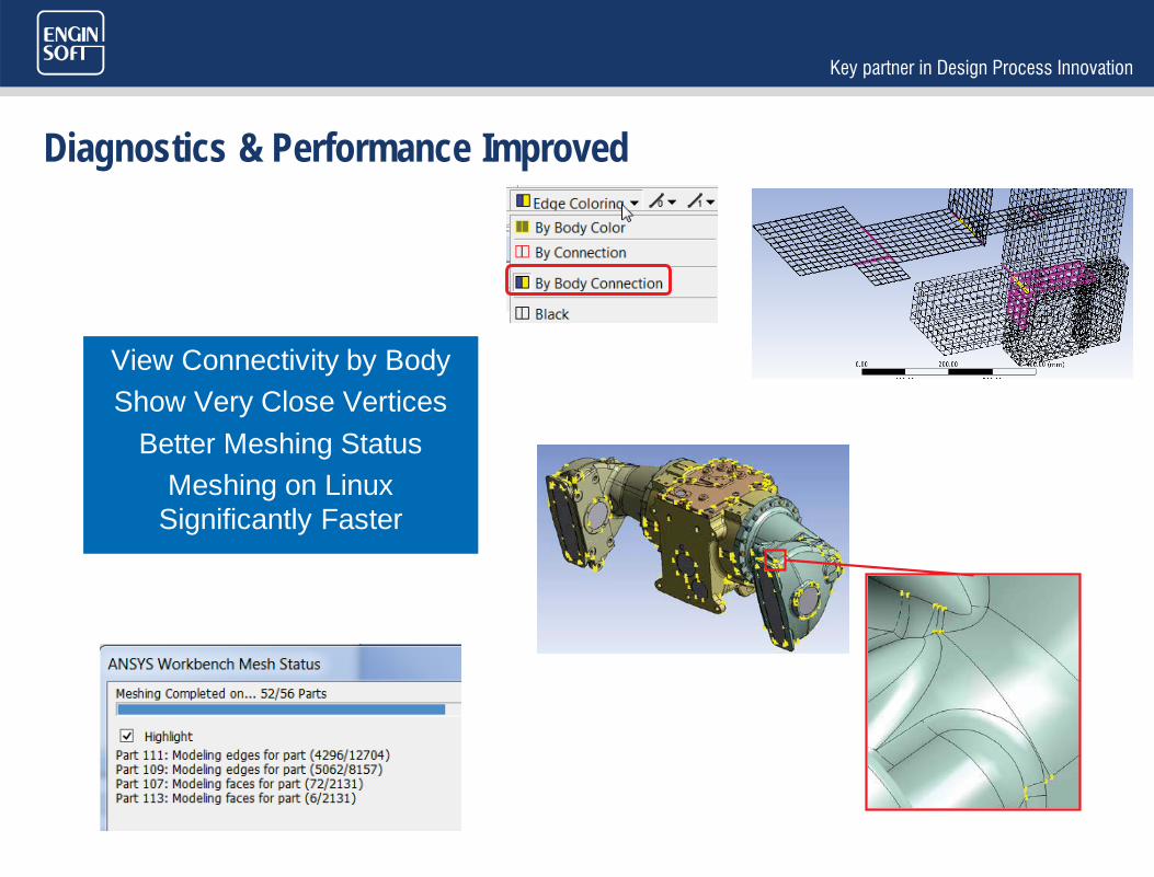
Diagnostics & Performance Improved
View Connectivity by BodyShow Very Close Vertices
Better Meshing StatusMeshing on Linux
Significantly Faster
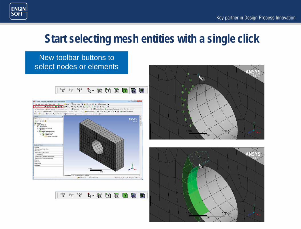
Start selecting mesh entities with a single clickNew toolbar buttons to
select nodes or elements

APDL scripts are not required anymore to generate deformed geometries based on results or create geometries from mesh
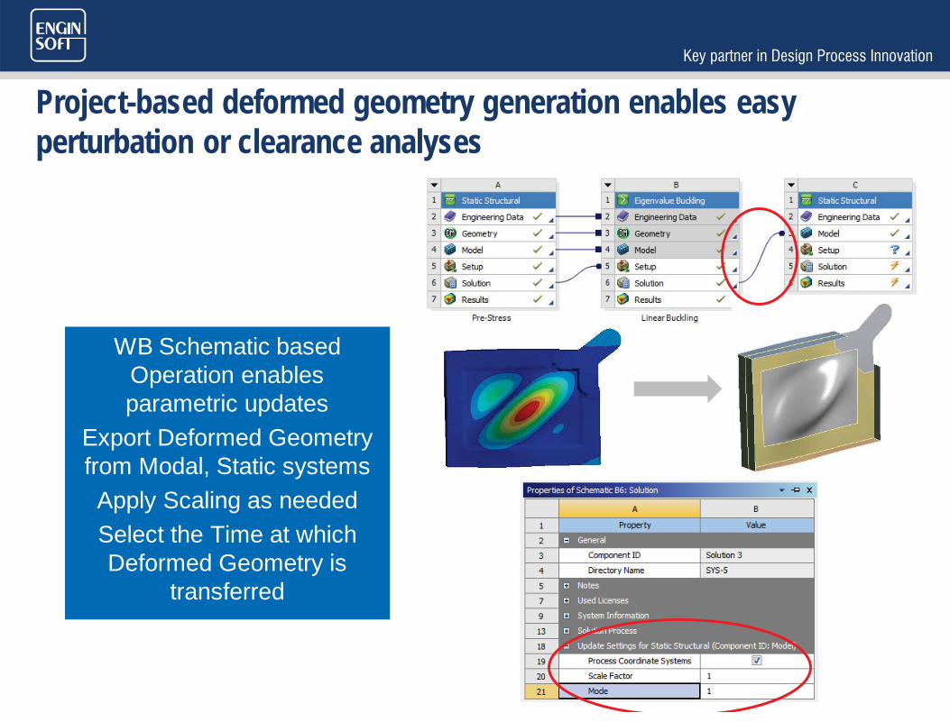
Project-based deformed geometry generation enables easy perturbation or clearance analyses
WB Schematic based Operation enables parametric updates
Export Deformed Geometry from Modal, Static systemsApply Scaling as neededSelect the Time at which Deformed Geometry is
transferred
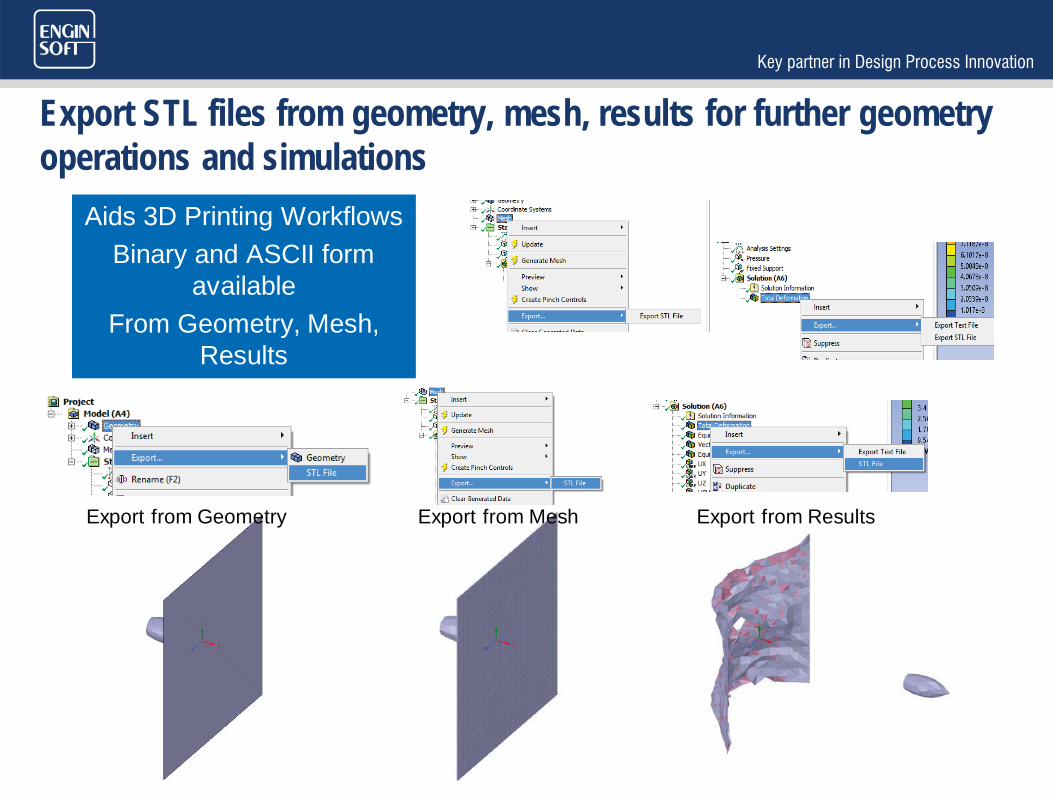
Export STL files from geometry, mesh, results for further geometry operations and simulations
Aids 3D Printing WorkflowsBinary and ASCII form
availableFrom Geometry, Mesh,
Results
Export from ResultsExport from Geometry Export from Mesh

Import of CDB files in a WB model imports more features to minimize manual additions to model
Import Node and Element Components
Import Beam and Pipe Elements
Import Cartesian and Cylindrical CSYS
Vertex Insertion Angle Helps capture features

MAKING USERS LIFE EASIER
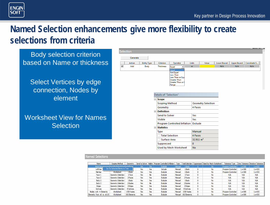
Named Selection enhancements give more flexibility to create selections from criteria
Body selection criterion based on Name or thickness
Select Vertices by edge connection, Nodes by
element
Worksheet View for Names Selection
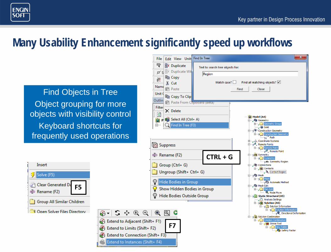
Many Usability Enhancement significantly speed up workflows
Find Objects in TreeObject grouping for more
objects with visibility controlKeyboard shortcuts for
frequently used operations
F5
F7
CTRL + G

Graphical enhancements make it easy to inspect complex models
Cap Sliced view
Color by Material
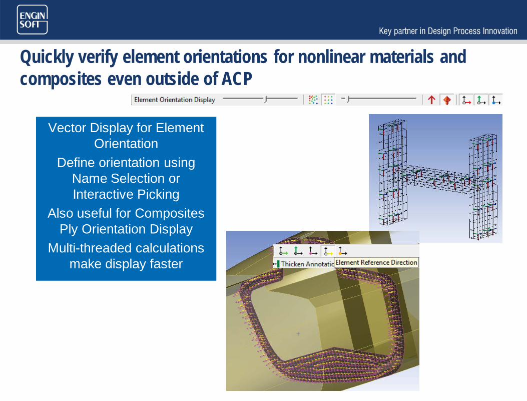
Quickly verify element orientations for nonlinear materials and composites even outside of ACP
Vector Display for Element Orientation
Define orientation using Name Selection or Interactive Picking
Also useful for Composites Ply Orientation Display
Multi-threaded calculations make display faster

Diagnostic tools help in monitoring and troubleshootingEnhanced Contact Trackers
Add Trackers during solution
Works for Local/Remote solves
Trackers Dynamically update as the solution
progresses
Context Sensitive option allows quick access to
quantities
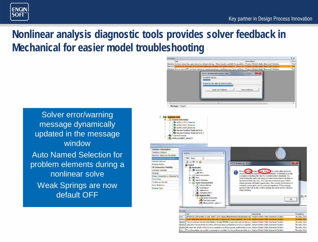
Nonlinear analysis diagnostic tools provides solver feedback in Mechanical for easier model troubleshooting
Solver error/warning message dynamically
updated in the message window
Auto Named Selection for problem elements during a
nonlinear solveWeak Springs are now
default OFF

PACKAGING

New packaging for structural mechanics simplifies the portfolio, provides true scalability between products and increases the span of applications available to structural users

From 11 products to 5, starting February 2016
R17.0

Mechanical Enterprise Mechanical Premium Mechanical Pro
Three levels - contents
All material models
Fracture Mechanics
Composite PrepPost Transient Dynamics
Explicit Dynamics (FE Solvers)
Rigid Dynamics with flexible bodies
Substructuring
Rezoning, Birth and Death
Hydrodynamics
Full Linear Dynamics: • Harmonic • Spectrum • Random Vibrations • Linear transient • Rotordynamics
Full rate-independent plasticity & Hyperelasticity
Basic Layered composites (no ACP)
Rigid Dynamics (pure rigid)
Coupled elements & physics
Full Thermal Fatigue
Static Modal Linear buckling
Full contact & joints Nonlinear geometric effects
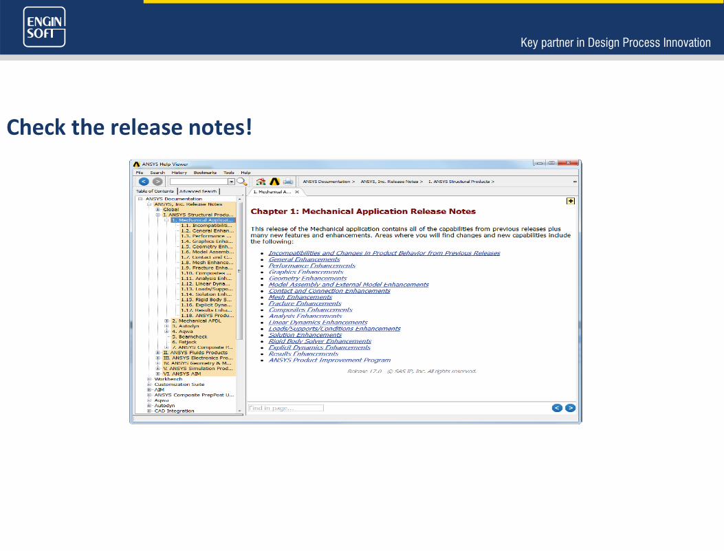
Check the release notes!

ANSYS Product Improvement Program (APIP)
• Understand user needs • Participation is voluntary
• “Anonymous” information sent via HTTPS
Secure Webserver
“Anonymous” Product Usage Data
Mechanical only for R17

THANK YOU