antenna designs for wireless medical implants
TRANSCRIPT
Dublin Institute of TechnologyARROW@DIT
Masters Engineering
2013
Antenna Designs for Wireless Medical Implants.Conor P. ConranIEEE, [email protected]
Follow this and additional works at: http://arrow.dit.ie/engmas
Part of the Electrical and Electronics Commons, and the Electromagnetics and PhotonicsCommons
This Theses, Masters is brought to you for free and open access by theEngineering at ARROW@DIT. It has been accepted for inclusion inMasters by an authorized administrator of ARROW@DIT. For moreinformation, please contact [email protected], [email protected],[email protected].
This work is licensed under a Creative Commons Attribution-Noncommercial-Share Alike 3.0 License
Recommended CitationConran, C. (2013).Antenna designs for wireless medical implants. Masters dissertation. Dublin Institute of Technology. doi:10.21427/D7P60G
Antenna Designs for Wireless Medical Implants
by
Conor Conran
This Report is submitted in partial fulfilment of the requirements of the Masters of
Science Degree in Electronic and Communications Engineering (DT085) of the
Dublin Institute of Technology
September 10th
, 2013
Supervisor: Prof. Max Ammann
Antenna and High Frequency Research Centre
Dublin Institute of Technology
Antenna Designs for Wireless Medical Implants Page 1
Declaration
I certify that this thesis which I now submit for examination for the award of a Master of
Science is entirely my own work and that it has not been taken from the work of others,
save and to the extent that such work has been cited and acknowledged within the text of
my work.
This thesis was prepared according to the regulations for postgraduates of the Dublin
Institute of Technology and has not been submitted in whole or in part for an award in any
other Institute or University.
The work reported on in this thesis conforms to the principles and requirements of the
Institute’s guidelines for ethics in research.
The Institute has permission to keep, to lend or to copy this thesis in whole or in part, on
the condition that any such use of the material of the thesis be duly acknowledged.
Dublin, 10. September 2011
______________________
Conor Conran

Antenna Designs for Wireless Medical Implants Page 2
Acknowledgements
I wish to thank Prof. Max Ammann and Dr. Matthias John of the Antenna and High
Frequency Research Centre, Dublin Institute of Technology, for their time, advice and
assistance in this research project.
I would also like to thank my father, Tom Conran, who inspired a love of radio
technology from my earliest years. This work is dedicated to him, to my loving wife
Inara and to our daughter Mia, who’s now taking her first wobbly steps on life’s
learning journey.

Antenna Designs for Wireless Medical Implants Page 3
Project Brief
Supervisor: Prof. Max Ammann, Antenna and High Frequency Research Centre.
Project Title: Antenna Designs for Wireless Medical Implants.
This project is suited for 1 student.
Tools: The following equipment was used during design and prototype production:
- Windows Workstation running CST Microwave Studio® simulation software.
- LPKF Protomat C60 CNC Milling Machine.
- VNWA3E Vector Network Analyser for empirical prototype refinement.
The following equipment was used during validation testing:
- Rohde and Swartz ZVA Vector Network Analyser.
- Rohde and Swartz FSP Spectrum Analyser.
- Rohde and Swartz SMC Signal Generator.
Project Type: Software modelling and hardware design.
Project Area: Radio frequency design, antenna prototype development and
performance evaluation.
Project Synopsis:
The aim of this project was to research, develop and test antenna designs for wireless
medical implants.
Phase 1 was to research academic and industry publications on the factors that affect
antennas implanted inside the human body and to devise a suitable method to test
them.
Phase 2 was to develop and simulate the performance of suitable antenna designs in
vivo using an appropriate software tool.
Phase 3 was to produce prototype antennas and evaluate their performance.
Antenna Designs for Wireless Medical Implants Page 4
Abstract
Active medical implants are devices that are surgically implanted inside the body.
They have been developed to treat a wide range of ailments and many require some
form of communications link with the outside world for diagnostics and maintenance.
Radio links promise a wide range of benefits over low frequency inductive coupling.
However, body tissue is a challenging environment for both the device and the radio
signal that it transmits. Innovation in medical technology is creating a demand for
higher bandwidth and resilient implant links, and this in turn is driving the
development of implantable antennas.
Many factors constrain antenna design choices. These include low signal power
levels, minimal space availability and the effect that tissue characteristics have on the
antenna. Most body tissues are highly dissipative and antennas must be specifically
designed for a high dielectric environment.
A review of spectrum band availability indicates that the 401 – 406 MHz and 2.4 GHz
bands are most suitable for implants. Multiband antennas were explored in the
research, but the design priority focussed on 401 – 406 MHz.
Custom antenna designs were simulated in software and prototypes were later
produced and tested in a range of different materials that closely imitate body tissue.
These tests revealed a discrepancy in the software simulations. It affected all the
prototypes, causing them to resonate at circa 150 MHz higher than the expected
frequency.
The simulation software’s transient domain solver was eventually identified as a
likely cause of the frequency offset, but in the interim the antenna designs were
progressed using empirical methods. The frequency domain solver has been found to
predict the resonant frequencies of dielectrically loaded implant antennas with better
accuracy than the time domain solver.
Two final designs were developed. Validation tests confirmed a good return loss of 10
to 20 dB in a replicated implant environment. The designs are meander line variants
of an inverted-L antenna.
The design process, test results and detailed specifications are set out hereafter.

Antenna Designs for Wireless Medical Implants Page 5
Table of Content DECLARATION ................................................................................................................................ 1
ACKNOWLEDGEMENTS ............................................................................................................... 2
PROJECT BRIEF .............................................................................................................................. 3
ABSTRACT ................................................................................................................... ..................... 4
TABLE OF CONTENT .................................................................................................................... 5
LIST OF FIGURES ............................................................................................................ ................ 6
LIST OF TABLES ............................................................................................................................... 8
1. INTRODUCTION TO WIRELESS MEDICAL IMPLANTS .......................................... 9
2. REVIEW OF IMPLANT TECHNOLOGY ....................................................................... 10
3. RADIO SPECTRUM AVAILABILITY FOR WIRELESS MEDICAL IMPLANTS ... 14
4. RESEARCH METHODOLOGY ........................................................................................ 19
5. EVALUATION OF MULTIBAND ANTENNA DESIGNS USING HIGH
IMPEDANCE FEED POINTS ............................................................................................ 21
6. ANTENNA MINIATURISATION TECHNIQUES APPLICABLE TO IMPLANT
DESIGNS .............................................................................................................................. 29
7. ANTENNA FEEDING ARRANGEMENTS - EVALUATION OF MICROSTRIP AND
COAXIAL TRANSMISSION LINES ................................................................................ 31
8. PROTOTYPE ANTENNA DEVELOPMENT .................................................................. 32
9. VALIDATION TESTING ................................................................................................... 45
10. RECONCILING S11 PREDICTIONS WITH MEASUREMENT DATA ...................... 49
11. FUTURE RESEARCH ........................................................................................................ 50
12. REFERENCES AND BIBLIOGRAPHY ........................................................................... 51
APPENDIX 1 DETAILED MECHANICAL SPECIFICATIONS OF THE
PROTOTYPE ANTENNAS .................................................................................. 54
APPENDIX 2 FREQUENCY BANDS AND CONDITIONS OF USE ...................................... 56
APPENDIX 3 SIMULATION RESULTS - ANALYSIS OF THE
OBSERVED DISCREPANCY BETWEEN THE
PREDICTIONS AND MEASUREMENT DATA .............................................. 58
APPENDIX 4 VNA VALIDATION TEST DATA - TABULAR S11 VALUES ........................ 63
APPENDIX 5 A SELECTION OF OTHER ANTENNA DESIGNS INVESTIGATED ..........65
Antenna Designs for Wireless Medical Implants Page 6
List of Figures
Figure 1: Wireless endoscope capsule (Source: Medi-Mation). 10
Figure 2: The measured propagation loss for a 403 MHz signal [9]. 12
Figure 3: 401 - 406 MHz band plan and conditions of use in Europe. 16
Figure 4: 2.4 - 2.5 GHz band plan and conditions of use in Europe. 17
Figure 5: 863 - 870 MHz band plan and conditions of use in Europe. 17
Figure 6: The S11 plot for a dipole antenna. 21
Figure 7: An OCF dipole antenna fed at a point located at 30% along its total length. 23
Figure 8: S11 of the antenna shown in Figure 7. 23
Figure 9: 403.5 MHz radiation pattern of the antenna in Figure 7. 24
Figure 10: 1.75 GHz radiation pattern of the antenna in Figure 7. 24
Figure 11: Physical construction of the PIFA. 25
Figure 12: S11 results for the PIFA design shown in Figure 11. 25
Figure 13: S11 at 403 MHz for various distances between the shorting strip and feed point. 26
Figure 14: S11 at 2.4 GHz for various distances between the shorting strip and feed point. 26
Figure 15: PIFA radiation pattern at 403.5 MHz. 27
Figure 16: PIFA radiation pattern at 2.45 GHz viewed along the axis. 16
Figure 17: Diagrams of the antenna’s upper monopole side (left) and its ground plane. 32
Figure 18: S11 of the monopole antenna shown in Figure 17. 32
Figure 19: The meandering Inverted-L monopole. 33
Figure 20: Further meandering and the capacitive hat. 33
Figure 21: The V47 model used to produce a handmade prototype. 34
Figure 22: The V47 model with S11 of 14 dB, centred on 403 MHz. 34
Figure 23: The initial handmade prototype. 35
Figure 24: Plot of S11 for the initial prototype with a glycerine. 35
Figure 25: Plot of S11 for the initial prototype without a glycerine. 36
Figure 26: Plot of S11 for the empirically modified prototype without a glycerine. 36
Figure 27: The V49 CST model. 37
Figure 28: The V50 CST model. 37
Figure 29: Plot of S11 for the V49 prototype without a glycerine. 38
Figure 30: Plot of S11 for the V50 prototype without a glycerine. 38
Figure 31: The empirical modifications made to the V49 prototype. 42
Figure 32: The empirical modifications made to the V50 prototype. 43
Figure 33: The final antenna prototypes. (Prototypes A, B, C and D) 44
Figure 34: S11 performance for prototypes A, B and C between 10 MHz and 3 GHz. 45
Figure 35: S11 performance for prototypes A, B and C between 380 MHz and 430 MHz. 45
Figure 36: S11 performance for prototype E between 10 MHz and 3 GHz. 47
Figure 37: S11 performance for prototype E between 380 MHz and 430 MHz. 47
Figure 38: Prototype A - meanders added to the monopole and the ground plane. 49
Figure 39: S11 prediction for Prototype A using the CST frequency domain solver. 49
Figure 40: Monopole side of Prototypes C showing track dimensions. 54
Figure 41: Ground plane side of Prototypes C showing track dimensions. 54
Figure 42: Monopole side of Prototype E showing track dimensions. 55
Figure 43: Monopole side of Prototype E showing track dimensions. 55
Figure 44: Skin Tissue Phantom with 2 mm thick glycerine. 58
Figure 45: Brain Tissue Phantom with 2 mm thick glycerine. 58
Figure 46: Bone Tissue Phantom with 2 mm thick glycerine. 58
Figure 47: Tap Water Phantom with 2 mm thick glycerine. 59
Figure 48: Fat Tissue Phantom with 2 mm thick glycerine. 59
Figure 49: The resonance frequency is 406 MHz with 4 mm of coaxial feeder. 60
Figure 50: The resonance frequency is 406 MHz with 125 mm of coaxial feeder. 60
Figure 51: Radiation pattern of prototype in phantom with a 2 mm glycerine shroud. 62
Figure 52: Radiation pattern of prototype in phantom without a shroud. 62
Figure 53: Antenna model with a CPW feeder. 65
Figure 54: Scalar prediction of S11 for the unloaded free space antenna model. 65
Figure 55: The CST antenna model with a surrounding 2 mm inner layer of glycerine (left) and
immersed in a 20 mm outer layer of tissue phantom (right). 66

Antenna Designs for Wireless Medical Implants Page 7
Figure 56: Scalar prediction of S11 for the dielectrically loaded antenna in the phantom. 66
Figure 57: The upper and lower surfaces of an early monopole with CPW feeder. 67
Figure 58: S11 measurement with the CPW feed antenna under dielectrically loaded conditions. 68

Antenna Designs for Wireless Medical Implants Page 8
List of Tables
Table 1: The effect of various phantom materials on antenna resonant frequency.
39
Table 2: Resonance frequencies and S11 performance of Prototypes A, B and C.
46
Table 3: Resonance frequency and S11 performance of Prototype E.
48
Table 4: List of Frequency Bands and Power Levels for Active Medical Implant Devices in Europe.
56
Table 5: List of Frequency Bands and Power Levels for Non-specific Short Range Devices in Europe.
56
Table 6: List of Frequency Bands and Permitted Channel Bandwidths for Active Medical Implant
Devices in the United States. 57
Table 7: List of frequency bands identified for use by Industrial, Scientific and Medical Applications in
the United States. 57
Table 8: Validation Data - Tabular S11 Values. 63
Antenna Designs for Wireless Medical Implants Page 9
1. Introduction to Wireless Medical Implants
An active medical implant is an electronic device surgically implanted inside a human
body or an animal. Implants have been developed to treat a diverse range of medical
conditions, including pacemakers for cardiovascular disorders, cochlear implants for
the hearing impaired and automated implantable medicine pumps to assist with
conditions requiring frequent delivery of intravenous drugs.
Most implants require a communications link with the outside world in order to
monitor the patient’s condition and to facilitate periodic device reprogramming.
Ongoing maintenance is also required, such as monitoring the condition of the
device’s internal battery. Once it has been implanted, the device is not removed again
for maintenance or battery replacement unless absolutely necessary [9], as to do so
requires the patient to undergo further surgery.
Communications with an in vivo implant requires a wireless communication link, as
wired links are undesirable from the perspective of the patient’s comfort and the risk
of infection [14]. Historically this used low frequency inductive coupling between a
coil inside the implant, and an external inductive probe.
The key limitations of inductive coupling are that it provides a relatively low
bandwidth communications channel of circa 30 kbps, and it can only communicate
over short distances of circa 10 cm [17] [23]. It also requires an external probe to be
placed directly on the patient’s skin for reliable communication, often requiring the
assistance of a trained medical professional [2].
An alternative to inductive coupling is to use an electromagnetic radio signal. This
provides more flexibility to patients and medical staff, allowing communications over
longer distances and with faster data rates. Patients can also be remotely monitored
using an intermediate wireless device in the home, reducing unnecessary visits to
healthcare clinics. Recent innovations in medical diagnostic tools require wideband
communication links which are beyond the capability of the traditional inductive
coupling approach [15] [16].
Implant radio links require compact and efficient antennas that fit either inside or
around the device’s case. The design of such antennas is complex. The human body is
a challenging environment which attenuates electromagnetic signals rapidly and
reduces both the efficiency and bandwidth [1] of antennas that are designed to operate
in free space.
Antenna Designs for Wireless Medical Implants Page 10
2. Review of Implant Technology
This section discusses innovation in implant technology, the antenna requirements in
this field and the technical challenges that must be overcome by the designer.
2.1 Innovations in Implant Technology that Influence the
Development of Antennas
Wireless endoscopes are an example of the kind of medical applications that influence
the development of implantable antennas. Diagnosing patients with digestive system
ailments traditionally involved inserting wired endoscopes into the digestive tract, so
that the affected area can be observed. This is an uncomfortable procedure for a
patient to undergo. There is also a risk of damaging the delicate lining of the digestive
tract, as well as the fact that the central six meters of the small intestine cannot be
reached using a wired endoscope [22].
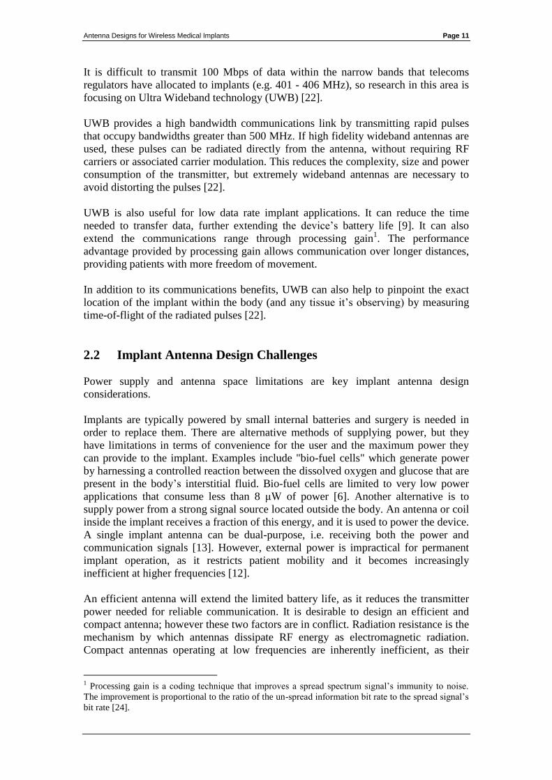
Pill-sized endoscope capsules can now deliver detailed images of the entire digestive
system without risking injury or discomfort to the patient.
Figure 1: Wireless endoscope capsule (Source: Medi-Mation).
The images may be stored in onboard memory and viewed after the capsule is
retrieved, however real-time viewing requires a wireless communications link.
Diagnostic imaging requires high resolution cameras which produce circa 100 Mbps
of data [8]. It is possible to compress this data, but the associated processing
electronics place extra demands on the limited battery capacity and space available
inside the 300 mm3
capsule [22].
Antenna Designs for Wireless Medical Implants Page 11
It is difficult to transmit 100 Mbps of data within the narrow bands that telecoms
regulators have allocated to implants (e.g. 401 - 406 MHz), so research in this area is
focusing on Ultra Wideband technology (UWB) [22].
UWB provides a high bandwidth communications link by transmitting rapid pulses
that occupy bandwidths greater than 500 MHz. If high fidelity wideband antennas are
used, these pulses can be radiated directly from the antenna, without requiring RF
carriers or associated carrier modulation. This reduces the complexity, size and power
consumption of the transmitter, but extremely wideband antennas are necessary to
avoid distorting the pulses [22].
UWB is also useful for low data rate implant applications. It can reduce the time
needed to transfer data, further extending the device’s battery life [9]. It can also
extend the communications range through processing gain1. The performance
advantage provided by processing gain allows communication over longer distances,
providing patients with more freedom of movement.
In addition to its communications benefits, UWB can also help to pinpoint the exact
location of the implant within the body (and any tissue it’s observing) by measuring
time-of-flight of the radiated pulses [22].
2.2 Implant Antenna Design Challenges
Power supply and antenna space limitations are key implant antenna design
considerations.
Implants are typically powered by small internal batteries and surgery is needed in
order to replace them. There are alternative methods of supplying power, but they
have limitations in terms of convenience for the user and the maximum power they
can provide to the implant. Examples include "bio-fuel cells" which generate power
by harnessing a controlled reaction between the dissolved oxygen and glucose that are
present in the body’s interstitial fluid. Bio-fuel cells are limited to very low power
applications that consume less than 8 μW of power [6]. Another alternative is to
supply power from a strong signal source located outside the body. An antenna or coil
inside the implant receives a fraction of this energy, and it is used to power the device.
A single implant antenna can be dual-purpose, i.e. receiving both the power and
communication signals [13]. However, external power is impractical for permanent
implant operation, as it restricts patient mobility and it becomes increasingly
inefficient at higher frequencies [12].
An efficient antenna will extend the limited battery life, as it reduces the transmitter
power needed for reliable communication. It is desirable to design an efficient and
compact antenna; however these two factors are in conflict. Radiation resistance is the
mechanism by which antennas dissipate RF energy as electromagnetic radiation.
Compact antennas operating at low frequencies are inherently inefficient, as their
1 Processing gain is a coding technique that improves a spread spectrum signal’s immunity to noise.
The improvement is proportional to the ratio of the un-spread information bit rate to the spread signal’s
bit rate [24].
Antenna Designs for Wireless Medical Implants Page 12
radiation resistance is low and their reactance is high [24]. Efficiency can be increased
by antenna design techniques and or lumped components to cancel reactance and
match dissimilar impedances, but these approaches increase antenna loss. Using high
frequencies to increase the efficiency of electrically small antennas is also impractical,
as it incurs greater signal attenuation in body tissues which typically have high
dielectric losses2 [9].
The limited power available in implants means that the transmitter output power
cannot be increased to compensate for antenna inefficiency or tissue attenuation.
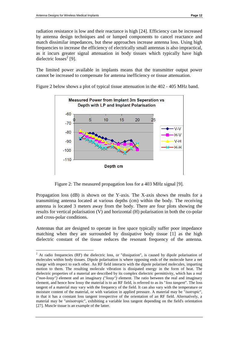
Figure 2 below shows a plot of typical tissue attenuation in the 402 - 405 MHz band.
Figure 2: The measured propagation loss for a 403 MHz signal [9].
Propagation loss (dB) is shown on the Y-axis. The X-axis shows the results for a
transmitting antenna located at various depths (cm) within the body. The receiving
antenna is located 3 meters away from the body. There are four plots showing the
results for vertical polarisation (V) and horizontal (H) polarisation in both the co-polar
and cross-polar conditions.
Antennas that are designed to operate in free space typically suffer poor impedance
matching when they are surrounded by dissipative body tissue [1] as the high
dielectric constant of the tissue reduces the resonant frequency of the antenna.
2 At radio frequencies (RF) the dielectric loss, or "dissipation", is caused by dipole polarisation of
molecules within body tissues. Dipole polarisation is where opposing ends of the molecule have a net
charge with respect to each other. An RF field interacts with the dipole polarised molecules, imparting
motion to them. The resulting molecule vibration is dissipated energy in the form of heat. The
dielectric properties of a material are described by its complex dielectric permittivity, which has a real
("non-lossy") element and an imaginary ("lossy") element. The ratio between the real and imaginary
element, and hence how lossy the material is to an RF field, is referred to as its "loss tangent". The loss
tangent of a material may vary with the frequency of the field. It can also vary with the temperature or
moisture content of the material, or with variation in applied pressure. A material may be "isotropic",
in that it has a constant loss tangent irrespective of the orientation of an RF field. Alternatively, a
material may be "anisotropic", exhibiting a variable loss tangent depending on the field's orientation
[27]. Muscle tissue is an example of the latter.
Antenna Designs for Wireless Medical Implants Page 13
Impedance matching to tissue is complicated by variations in tissue characteristics.
The dielectric and permittivity properties of tissue change from organ to organ and
often also vary over time [1] [4]. For example, the characteristics of tissue may
change depending on the individual's current level of hydration or as food transits
through a nearby region of the digestive system.
Dissipative tissue also reduces antenna bandwidth [1]. If not mitigated this negates
some benefits of UWB.
The proximity of other implants in the vicinity of the antenna can increase attenuation
and even the position of the patient's limbs can increase propagation loss in the
transmission path [11].
Non-deterministic sources of loss (such as tissue variation and limb position) must be
mitigated by an appropriate fade margin in the link budget or the communications link
with the implant becomes less reliable. Providing an adequate fade margin places
greater demands on antenna efficiency.
The choice of antenna shrouding material is also an important design consideration.
An antenna that is in direct contact with body tissue occupies less space than an
antenna surrounded by a shroud of non-dissipative insulation material, but it results in
higher loss due to tissue absorption [3]. Bio-compatible insulation avoids adverse
tissue reaction and improves impedance matching [1] [20] [21]. The use of a shroud
material with a high dielectric constant, low conductivity and low loss tangent can
further reduce losses in dissipative body tissue, as it concentrates the electric near
field components closer to the antenna, keeping them out of the surrounding
dissipative tissue.
If the dielectric constant of the insulation material is between 40 and 50, similar to
body tissue, then wideband antenna matching can be improved. Polyether-ether-
ketone (PEEK) titanium-oxide and glycerine are considered to be suitable materials
with a high dielectric constant and low permittivity [1].
Antenna Designs for Wireless Medical Implants Page 14
3. Radio Spectrum Availability for Wireless Medical
Implants
This section concentrates on the European and United States regulatory environments
and identifies suitable frequencies for implant antenna designs.
The frequency of operation is a fundamental design consideration for any antenna.
The choice of frequency band is constrained by spectrum allocations that are decided
by regulatory organisations. These organisations decide how different frequencies are
used at the national, regional and global levels. Frequency bands are often harmonised
for a common use across many countries for the benefit of users and manufacturers.
Radio spectrum allocations and their associated regulatory regimes differ greatly
between Europe and the United States. However there are a number of spectrum
bands common to both regions which have been identified for use by exempted
wireless devices, including wireless medical implants.
In Europe and the United States there are two possible approaches to operating
wireless medical implant devices in a licence exempt environment (i.e. without
requiring a licence to transmit). These options are:
to operate in spectrum specifically identified for medical implant
devices; or
to operate in spectrum identified for exempt use more generally, where
implants would share the spectrum with other applications and users.
3.1 Spectrum Availability in Europe
In Europe both options are possible under the Short Range Devices (SRD) regime
which exempts certain categories of wireless devices. SRDs, as implied by their
name, are devices intended to communicate over distances of a few meters up to
several hundred meters. They are permitted to operate within specific frequency bands
on the basis that they may not cause interference to other users and they may not
claim protection from interference arising from other users. SRDs often share the
same spectrum as licensed users and critical safety of life services. This is permitted
on the basis that SRDs radiate low power levels and they must also incorporate
specified mitigation3 measures so that they coexist with other spectrum users.
The SRD bands and conditions of use are listed in ERC Recommendation 70-034.
This is a living document and is regularly updated by CEPT ECC5 to reflect changes
in its spectrum policy. Within the SRD framework, implant devices could operate in
bands identified for:
3 Such mitigation measures include limitations on transmission duty cycle or protocols such as "listen-
before-talk". 4 This document is available at http://www.erodocdb.dk/Docs/doc98/official/pdf/Rec7003e.PDF
5 The Electronic Communications Committee (ECC) is the CEPT body with responsibility for
radiocommunications and telecommunications matters. The ECC webpage is: http://www.cept.org/ecc
Antenna Designs for Wireless Medical Implants Page 15
“Active Medical Implants and Their Associated Peripherals”. Under this option,
implant devices could operate in a limited number of bands, but with the benefit of a
relatively predictable interference environment. Medical devices only have to coexist
with the primary users of the bands and do not suffer interference from other
exempted devices. A full list of these bands is presented in Appendix 2.
“Non-Specific Short Range Devices”. Under this option, implants could operate in a
wider selection of frequency bands, but they would share these bands with other
licence exempt equipment, such as Bluetooth enabled devices, RFID tags and 802.11
computer networks (WiFi). It is likely that implant devices operating in these bands
would suffer interference from many sources. Moreover, as new exempted devices
and applications are continually being introduced into the market, their cumulative
activity is likely to increase the level of interference within these bands in the future.
For this reason the non-specific SRD bands cannot provide a predictable interference
environment over the longer term.
Given the long service life of many implants (typically 10 to 15 years), uncertainty
over the long-term reliability of their wireless links is undesirable. This is particularly
the case for devices that treat critical medical conditions. A full list of the bands for
non-specific SRDs is presented in Appendix 2.
3.2 Spectrum Availability in the United States
In the United States there is no direct equivalent to the European SRD regime, but the
Federal Communications Commission6 (FCC) has identified a number of bands
between 401 MHz and 457 MHz for what is referred to as the "Medical Device Radio
Communications Service" or “MedRadio” (These bands include the 401 – 406 MHz
band). The full list of MedRadio bands available in the United States is provided in
Appendix 2.
Devices may also operate on a non-interference and non-protected basis in the
Industrial, Scientific and Medical (ISM) bands7. The ISM bands cannot provide
implant users with a long-term predictable interference environment for the same
reasons that apply to non-specific SRD use in Europe. Appendix 2 provides a list of
the permitted ISM bands in the United States.
3.3 Candidate Bands for the Proposed Development of Medical
Implant Antennas
A number of practical factors constrain the selection of candidate frequency bands for
consideration. These factors include:
6 The Federal Communications Commission is the Government body tasked with regulating the use of
the radio spectrum resource in the United States. See: http://www.fcc.gov for details. 7 This is subject to mitigation requirements similar to those applying to European SRD spectrum use.
Antenna Designs for Wireless Medical Implants Page 16
Antennas optimised for bands that are available in both Europe and the United
States will yield greater economic and social benefits for users and device
manufacturers.
Skin penetration loss and the propagation loss through body tissue will have a
significant impact at higher frequencies. It is therefore likely that bands in
spectrum significantly above 2.5 GHz should not be considered (for example
5.8 GHz, 24 GHz and above).
With regard to these factors, there are three bands that are suitable candidates for
antenna research. These are analysed in turn below with reference to the regulatory
regime that applies in Europe.
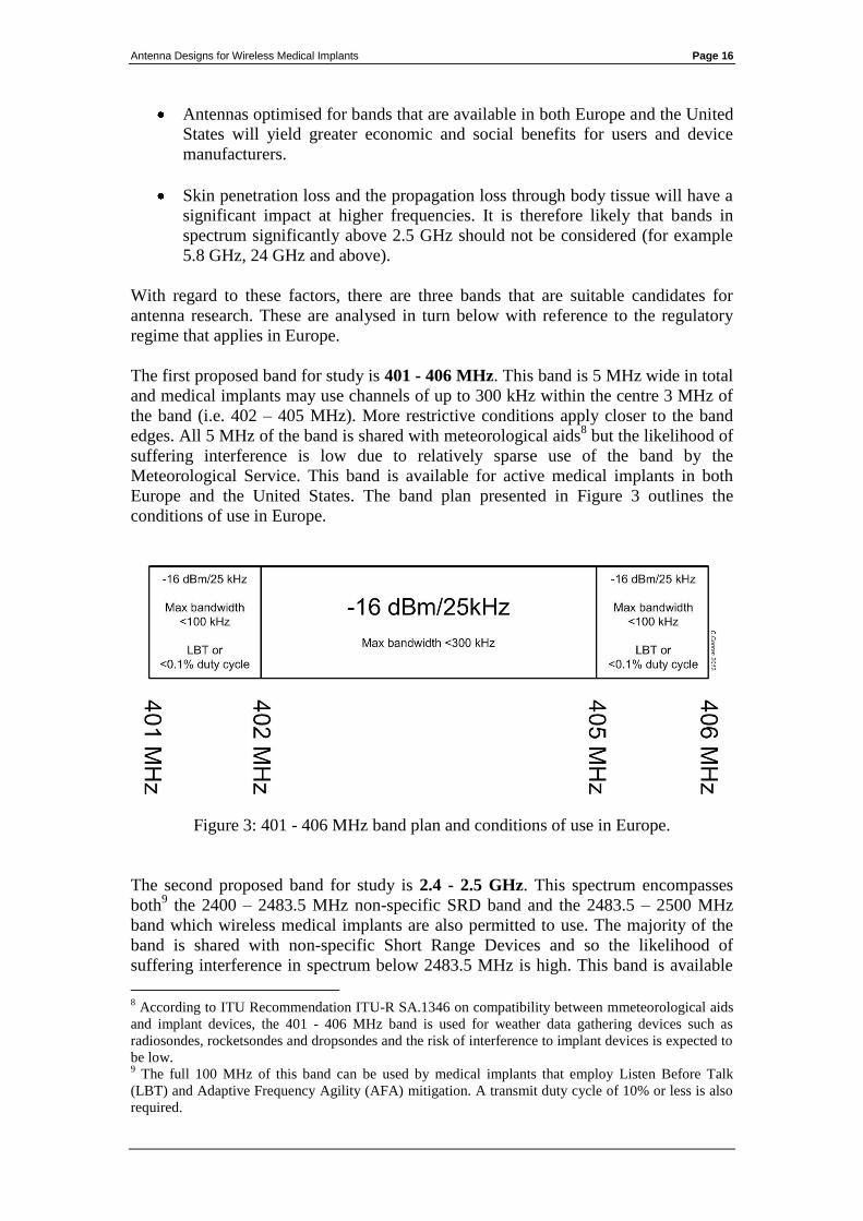
The first proposed band for study is 401 - 406 MHz. This band is 5 MHz wide in total
and medical implants may use channels of up to 300 kHz within the centre 3 MHz of
the band (i.e. 402 – 405 MHz). More restrictive conditions apply closer to the band
edges. All 5 MHz of the band is shared with meteorological aids8 but the likelihood of
suffering interference is low due to relatively sparse use of the band by the
Meteorological Service. This band is available for active medical implants in both
Europe and the United States. The band plan presented in Figure 3 outlines the
conditions of use in Europe.
Figure 3: 401 - 406 MHz band plan and conditions of use in Europe.
The second proposed band for study is 2.4 - 2.5 GHz. This spectrum encompasses
both9 the 2400 – 2483.5 MHz non-specific SRD band and the 2483.5 – 2500 MHz
band which wireless medical implants are also permitted to use. The majority of the
band is shared with non-specific Short Range Devices and so the likelihood of
suffering interference in spectrum below 2483.5 MHz is high. This band is available
8 According to ITU Recommendation ITU-R SA.1346 on compatibility between mmeteorological aids
and implant devices, the 401 - 406 MHz band is used for weather data gathering devices such as
radiosondes, rocketsondes and dropsondes and the risk of interference to implant devices is expected to
be low. 9 The full 100 MHz of this band can be used by medical implants that employ Listen Before Talk
(LBT) and Adaptive Frequency Agility (AFA) mitigation. A transmit duty cycle of 10% or less is also
required.

Antenna Designs for Wireless Medical Implants Page 17
in both Europe and the United States. The band plan presented in Figure 4 outlines the
conditions of use in Europe:
Figure 4: 2.4 - 2.5 GHz band plan and conditions of use in Europe.
A third band for consideration is 863 - 870 MHz, however this band is only available
in Europe10
. The band is shared with non-specific Short Range Devices and the
likelihood of suffering interference is high. A possible alternative band in the United
States market is the 902 – 928 MHz ISM band, as it is close to 870 MHz. A single
antenna may be able to cover both of these bands. The 863 - 870 MHz band plan
presented in Figure 5 outlines the conditions of use in Europe:
Figure 5: 863 - 870 MHz band plan and conditions of use in Europe.
10
This band is 7 MHz wide. It can be used in Europe by wireless medical implants employing Direct
Sequence Spread Spectrum (DSSS) with Listen Before Talk (LBT) and Adaptive Frequency Agility
(AFA) mitigation techniques.
Antenna Designs for Wireless Medical Implants Page 18
3.4 Conclusions on Antenna Design Frequency
Antenna design should focus on the following bands in order of priority;
The highest priority is the 401 – 406 MHz band. This band is harmonised for
implant use in both Europe and the US. It also affords implanted devices the
greatest protection against interference as it is not available to other exempted
devices.
Of lesser priority is the 2.4 - 2.5 GHz band. This band is available for exempt
use in most parts of the world. However, implants would not be protected
from interference caused by other exempted devices and high power users11
.
The lowest priority is a combination of the 863 – 870 MHz and/or 915 MHz
bands. Considered together, these bands could accommodate users in both
Europe (863 MHz) and the US (915 MHz) but the bandwidth available is low
and implanted devices are not protected from interference.
It is desirable to design a multi-band antenna that can be used in both the 401 – 406
MHz and 2.4 - 2.5 GHz bands. This is because some implant devices12
use a 2.4 GHz
wakeup signal to initiate a communications session in the 401 – 406 MHz band. This
allows the device to switch off much of its receiver circuitry when it is not required,
helping to conserve battery power.
11
In parts of the 2.4 GHz band, SRD devices such as Bluetooth and WiFi adapters can transmit at
power levels of 100 mW. In many countries the Radio Amateur Service is also permitted to transmit at
power levels of up to 400 Watts (26dBW) EIRP. 12
An example of an implant processor chip with an integrated 2.4 GHz "wake up" receiver is the
Zarlink ZL70102. Further information is available at http://ulp.zarlink.com/zarlink/hs/82_ZL70102.htm
Antenna Designs for Wireless Medical Implants Page 19
4. Research Methodology
This section provides a brief description of the procedure used to design, build and
test the prototype antennas that were developed for the bands discussed in the
preceding section.
4.1 Computer Simulation and Prototyping
The antenna designs were modelled using CST Microwave Studio® simulation
software (CST). Early antenna models assumed a free space environment in order to
reduce the computation time required for computer simulation [20]. Later designs
were simulated in body tissue (phantom).
The early prototype antennas were handmade for proof of concept. A Computer
Numerical Control (CNC) milling machine was used to print later prototypes on FR4
substrate13
.
The antenna prototypes were wrapped in meat or immersed in artificial liquid-based
phantoms. The literature suggested a liquid phantom14
consisting of sugar, salt and
Hydroxyethylcellulose (HEC) diluted in deionised water. [3] [4] [25].
4.2 Prototype Validation Testing
In order to verify that the prototypes met the performance predicted in the computer
simulations, the frequency response and return loss (S11) of the antennas was
measured using a Rohde and Swartz ZVA Vector Network Analyser (VNA).
Revised prototypes were milled and retested in an iterative process to develop an
understanding of the effect of immersion in body tissue.
4.3 Calibration of Test Equipment
The prototypes were fully immersed in the phantom during testing in order to
accurately simulate an in vivo environment. RF connectors were not mounted directly
on the prototype antennas, as phantom material ingress into the connector or test cable
could distort the test results. To prevent this, rigid coaxial "pigtails" were soldered
directly onto the prototype antennas so that the test equipment’s connectors and cables
did not come into contact with the phantom. However, this complicated the test
equipment calibration procedure.
In order to accurately calibrate a VNA for phase and impedance measurements, the
reference plane must be set at the location of the antenna's feed point. If the reference
plane is not correctly set, then cable effects (propagation delay and attenuation) add
uncertainty to impedance and S11 measurement results. As the prototypes used pigtail
13
The FR4 substrate used for the prototypes was 0.4 mm thick with double-sided 35 µm thick copper
surfaces. 14
The resulting mixture had a dielectric constant of 49, relative permeability of 1 and conductivity of
0.6 S/m which closely simulates the average properties of human body tissue [3] [4] [25].
Antenna Designs for Wireless Medical Implants Page 20
cables instead of connectors, it was not possible to connect precision terminations15
directly at the feed point. A 15 cm pigtail could distort measurements if it is ignored
during calibration.
Two calibration pigtails were prepared so that the VNA's reference plane could be set
precisely at the antenna feed point. These were sections of coax with open and shorted
cable ends. They were identical to the pigtails on the antenna prototypes and they
were used as a proxy for open and short terminations during the calibration procedure.
4.4 Ferrite Chokes on Feeders
In order to test a prototype antenna it is necessary to connect it to a VNA. RF current
may flow from an antenna's ground plane, along the outside of the coaxial cable in
common mode. It can also conduct electrical noise to the antenna from mains wiring,
via the conductive case of test equipment. Both of these conditions are undesirable.
Common mode currents flowing on the cable are of particular concern when testing
electrically small antennas, as the feeder acts as an electrically long antenna element.
This can reduce the resonance frequency of the antenna producing misleading test
results.
In order to reduce the effect of common mode current, a ferrite sleeve was placed over
the coaxial feeder close to each antenna's feed point.
15
Precision terminations are required to create known "open", "short" and "50 Ω" terminated
conditions at the end of the test cables so that the VNA can compensate for the distortion effects of the
cables.
Antenna Designs for Wireless Medical Implants Page 21
5. Evaluation of Multiband Antenna Designs Using High
Impedance Feed-points
5.1 Introduction to Off-Centre Feed Dipoles
A half-wave centre-feed dipole in free space has an input impedance of 72 Ω at its
fundamental resonance frequency. The impedance is resistive (i.e. real) with a low
reactive (imaginary) component. The antenna presents similar input impedances on
odd16
harmonic frequencies, resulting in a good impedance match to 72 Ω. On even
harmonic frequencies the antenna has high impedance, resulting in a poor match.
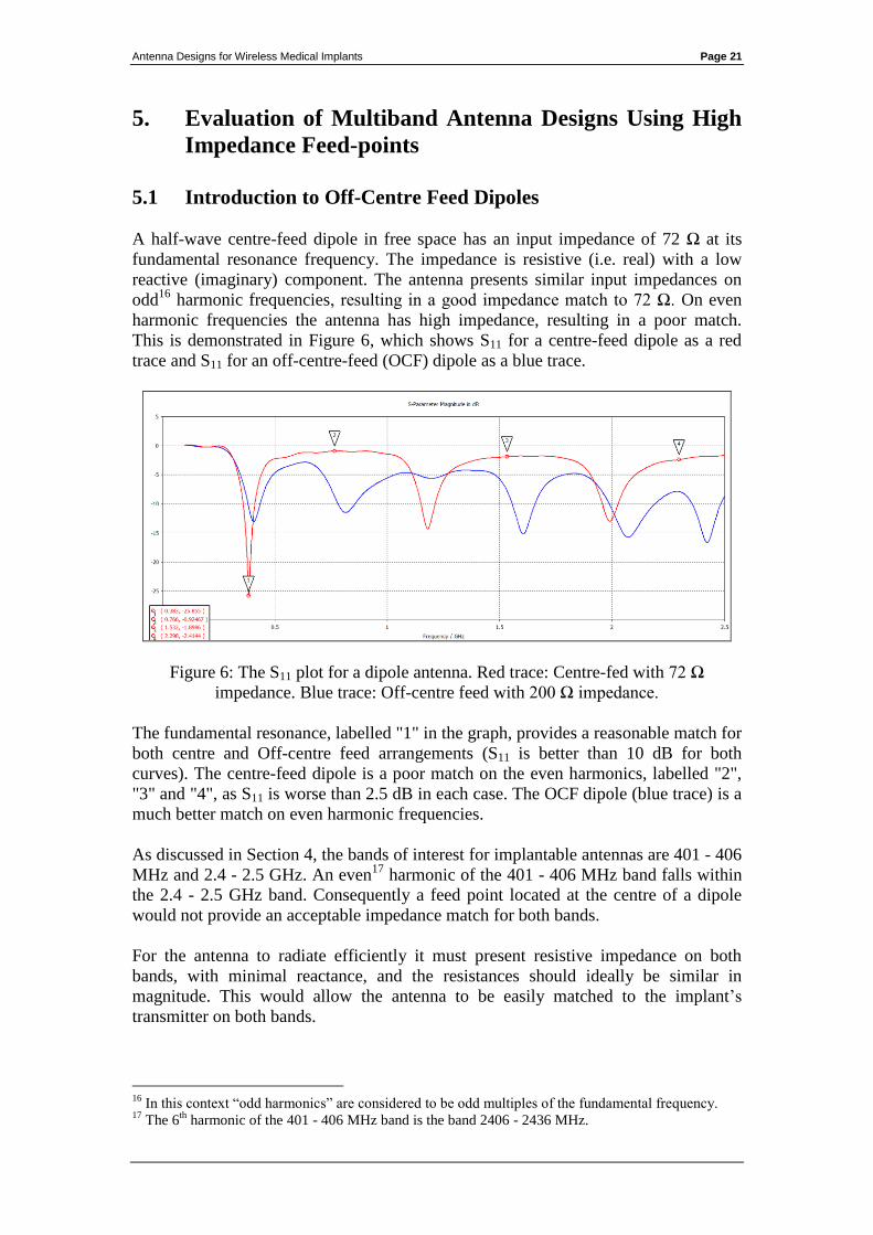
This is demonstrated in Figure 6, which shows S11 for a centre-feed dipole as a red
trace and S11 for an off-centre-feed (OCF) dipole as a blue trace.
Figure 6: The S11 plot for a dipole antenna. Red trace: Centre-fed with 72 Ω
impedance. Blue trace: Off-centre feed with 200 Ω impedance.
The fundamental resonance, labelled "1" in the graph, provides a reasonable match for
both centre and Off-centre feed arrangements (S11 is better than 10 dB for both
curves). The centre-feed dipole is a poor match on the even harmonics, labelled "2",
"3" and "4", as S11 is worse than 2.5 dB in each case. The OCF dipole (blue trace) is a
much better match on even harmonic frequencies.
As discussed in Section 4, the bands of interest for implantable antennas are 401 - 406
MHz and 2.4 - 2.5 GHz. An even17
harmonic of the 401 - 406 MHz band falls within
the 2.4 - 2.5 GHz band. Consequently a feed point located at the centre of a dipole
would not provide an acceptable impedance match for both bands.
For the antenna to radiate efficiently it must present resistive impedance on both
bands, with minimal reactance, and the resistances should ideally be similar in
magnitude. This would allow the antenna to be easily matched to the implant’s
transmitter on both bands.
16
In this context “odd harmonics” are considered to be odd multiples of the fundamental frequency. 17
The 6th
harmonic of the 401 - 406 MHz band is the band 2406 - 2436 MHz.
Antenna Designs for Wireless Medical Implants Page 22
Early antenna designs that were developed for this thesis focused on a multi-band
approach known as "Off-centre Feeding". This was the approach used to generate the
blue trace in Figure 6. It can be seen that the blue trace has 5 resonant frequencies,
while the red trace (centre feed) only has 3. The OCF approach is borrowed from
amateur radio designs, which achieve acceptable antenna efficiency and impedance
matching across a number of harmonically related bands.
At its fundamental resonance, the feed point impedance of a dipole is lowest at its
centre and approaches infinity towards its open ends. Varying the feed point location
allows the antenna to be used on its fundamental frequency and on its 2nd
, 4th
, 5th
and
6th
harmonics. Typically a distance 20% to 30% away from one end is often chosen,
as at this location the dipole presents a resistive impedance of circa 200 Ω on all of
these frequencies with low reactance.
The OCF design has some limitations. It is clear from Figure 6 that operation on the
3rd
harmonic is degraded and impedance matching a 200 Ω feed point impedance to a
50 Ω or 72 Ω transmission line requires a 4:1 transformer.
5.2 Modelling Off-Centre Feed Dipole Impedance Matching in
CST
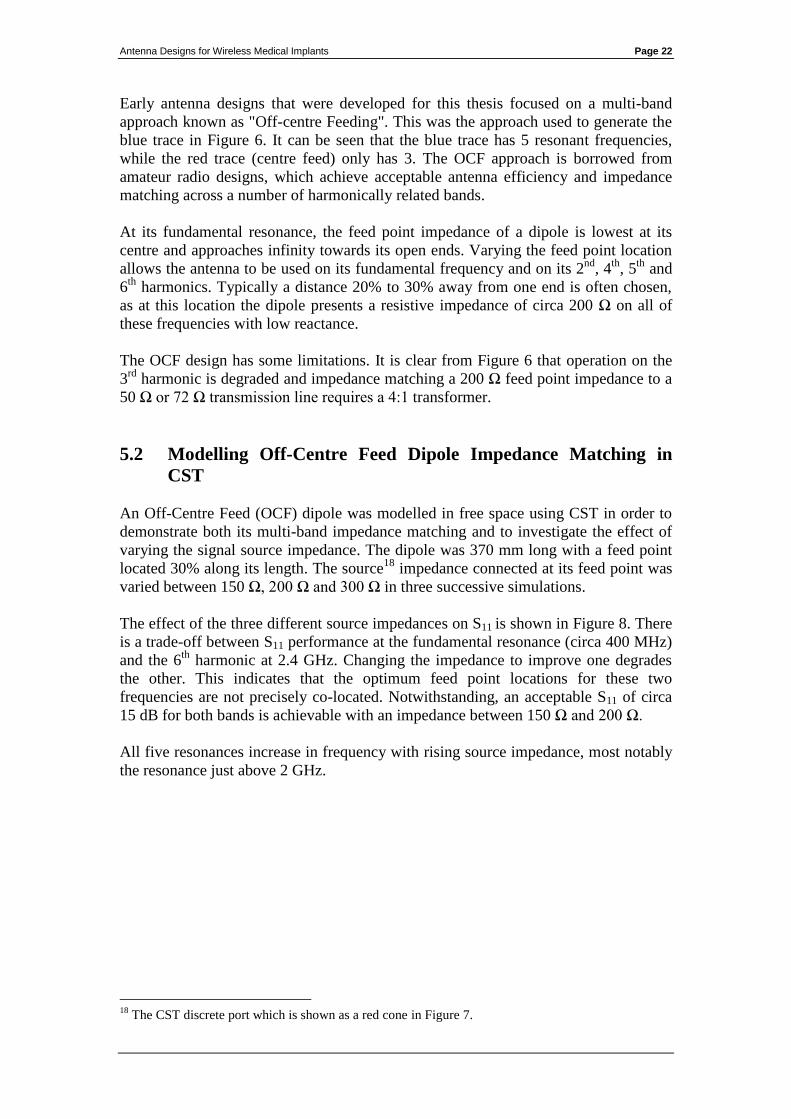
An Off-Centre Feed (OCF) dipole was modelled in free space using CST in order to
demonstrate both its multi-band impedance matching and to investigate the effect of
varying the signal source impedance. The dipole was 370 mm long with a feed point
located 30% along its length. The source18
impedance connected at its feed point was
varied between 150 Ω, 200 Ω and 300 Ω in three successive simulations.
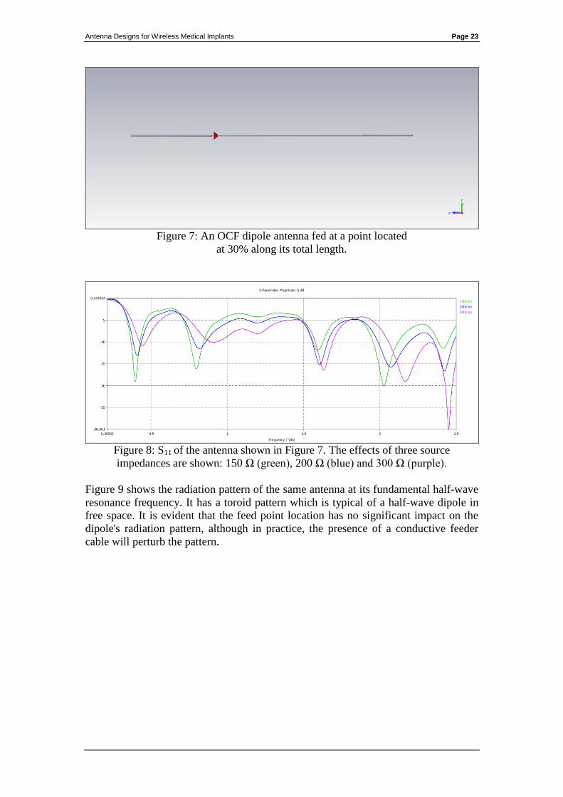
The effect of the three different source impedances on S11 is shown in Figure 8. There
is a trade-off between S11 performance at the fundamental resonance (circa 400 MHz)
and the 6th
harmonic at 2.4 GHz. Changing the impedance to improve one degrades
the other. This indicates that the optimum feed point locations for these two
frequencies are not precisely co-located. Notwithstanding, an acceptable S11 of circa
15 dB for both bands is achievable with an impedance between 150 Ω and 200 Ω.
All five resonances increase in frequency with rising source impedance, most notably
the resonance just above 2 GHz.
18
The CST discrete port which is shown as a red cone in Figure 7.
Antenna Designs for Wireless Medical Implants Page 23
Figure 7: An OCF dipole antenna fed at a point located
at 30% along its total length.
Figure 8: S11 of the antenna shown in Figure 7. The effects of three source
impedances are shown: 150 Ω (green), 200 Ω (blue) and 300 Ω (purple).
Figure 9 shows the radiation pattern of the same antenna at its fundamental half-wave
resonance frequency. It has a toroid pattern which is typical of a half-wave dipole in
free space. It is evident that the feed point location has no significant impact on the
dipole's radiation pattern, although in practice, the presence of a conductive feeder
cable will perturb the pattern.
Antenna Designs for Wireless Medical Implants Page 24
Figure 9: 403.5 MHz radiation pattern of the antenna in Figure 7.
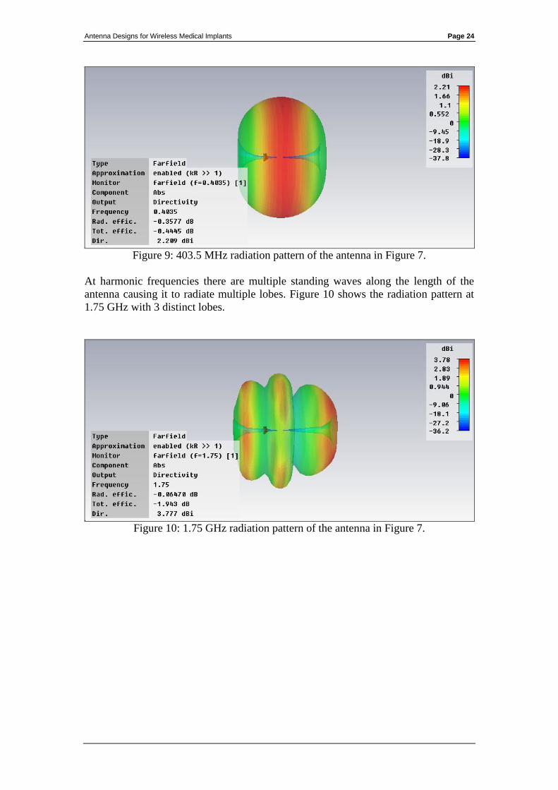
At harmonic frequencies there are multiple standing waves along the length of the
antenna causing it to radiate multiple lobes. Figure 10 shows the radiation pattern at
1.75 GHz with 3 distinct lobes.
Figure 10: 1.75 GHz radiation pattern of the antenna in Figure 7.
Antenna Designs for Wireless Medical Implants Page 25
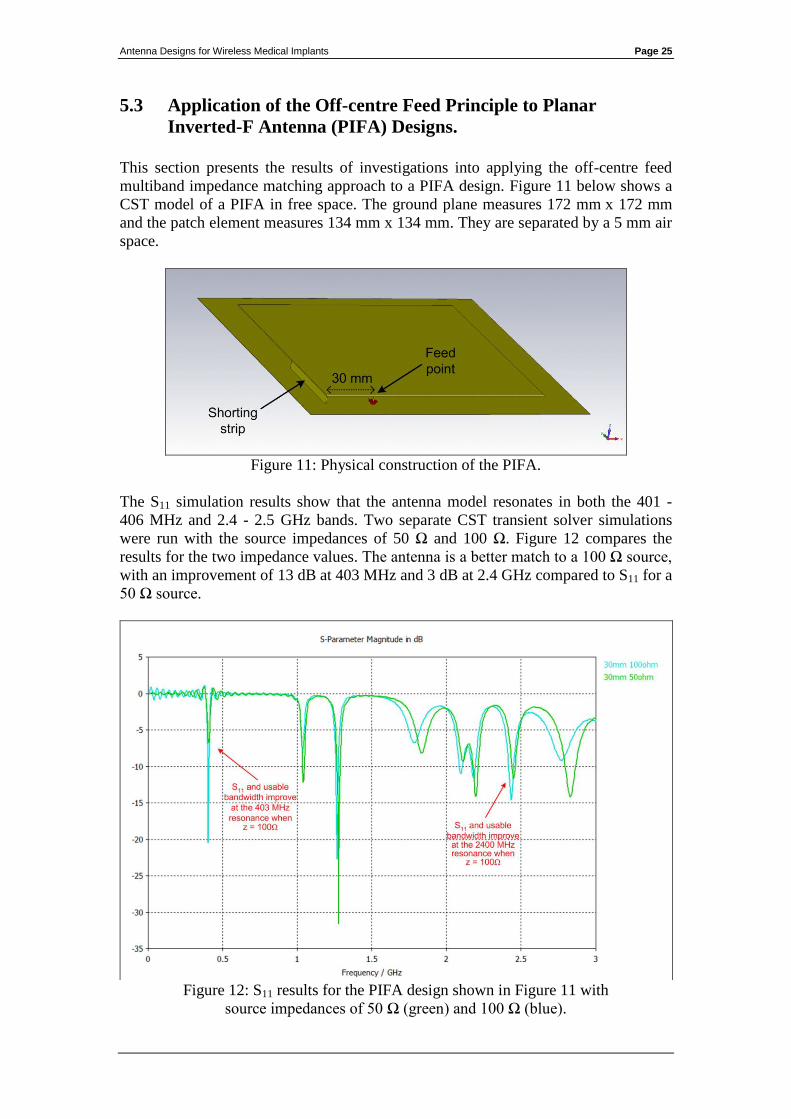
5.3 Application of the Off-centre Feed Principle to Planar
Inverted-F Antenna (PIFA) Designs.
This section presents the results of investigations into applying the off-centre feed
multiband impedance matching approach to a PIFA design. Figure 11 below shows a
CST model of a PIFA in free space. The ground plane measures 172 mm x 172 mm
and the patch element measures 134 mm x 134 mm. They are separated by a 5 mm air
space.
Figure 11: Physical construction of the PIFA.
The S11 simulation results show that the antenna model resonates in both the 401 -
406 MHz and 2.4 - 2.5 GHz bands. Two separate CST transient solver simulations
were run with the source impedances of 50 Ω and 100 Ω. Figure 12 compares the
results for the two impedance values. The antenna is a better match to a 100 Ω source,
with an improvement of 13 dB at 403 MHz and 3 dB at 2.4 GHz compared to S11 for a
50 Ω source.
Figure 12: S11 results for the PIFA design shown in Figure 11 with
source impedances of 50 Ω (green) and 100 Ω (blue).
Antenna Designs for Wireless Medical Implants Page 26
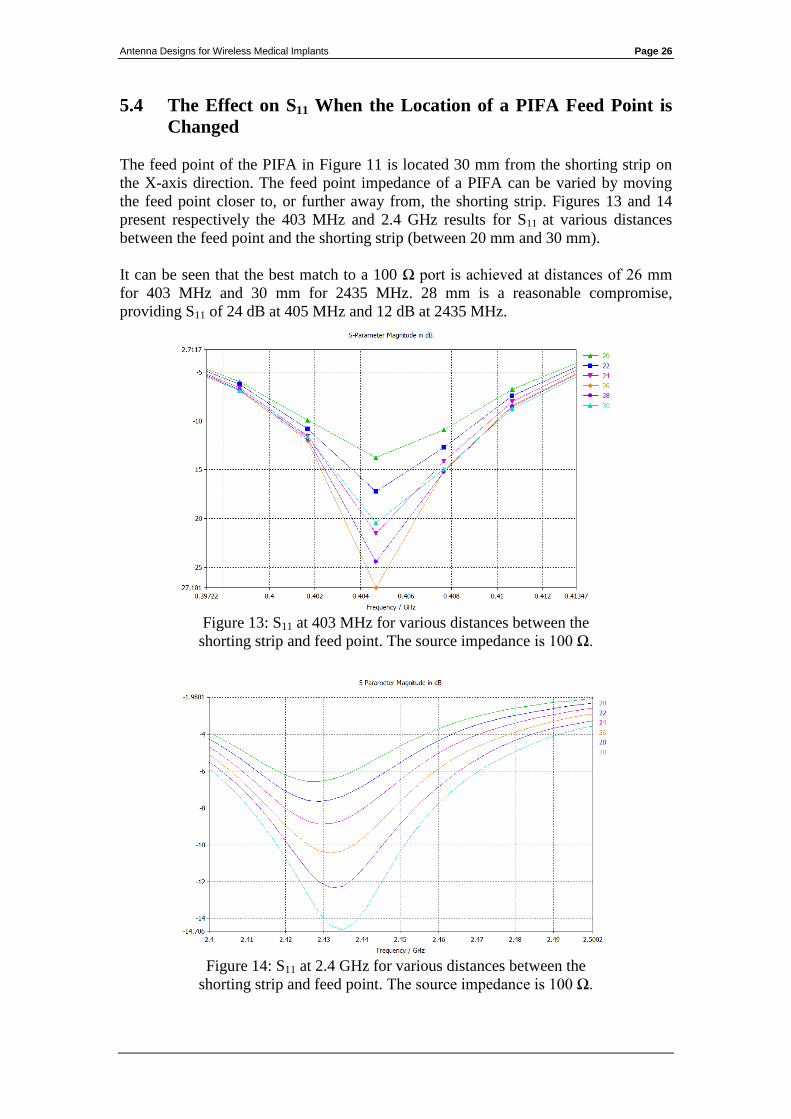
5.4 The Effect on S11 When the Location of a PIFA Feed Point is
Changed
The feed point of the PIFA in Figure 11 is located 30 mm from the shorting strip on
the X-axis direction. The feed point impedance of a PIFA can be varied by moving
the feed point closer to, or further away from, the shorting strip. Figures 13 and 14
present respectively the 403 MHz and 2.4 GHz results for S11 at various distances
between the feed point and the shorting strip (between 20 mm and 30 mm).
It can be seen that the best match to a 100 Ω port is achieved at distances of 26 mm
for 403 MHz and 30 mm for 2435 MHz. 28 mm is a reasonable compromise,
providing S11 of 24 dB at 405 MHz and 12 dB at 2435 MHz.
Figure 13: S11 at 403 MHz for various distances between the
shorting strip and feed point. The source impedance is 100 Ω.
Figure 14: S11 at 2.4 GHz for various distances between the
shorting strip and feed point. The source impedance is 100 Ω.
Antenna Designs for Wireless Medical Implants Page 27
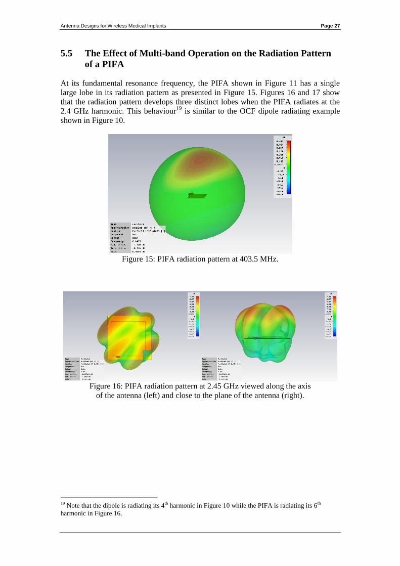
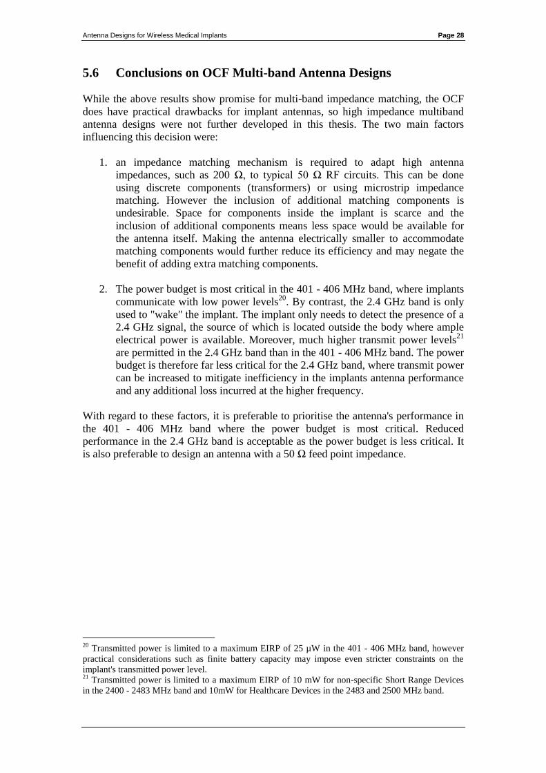
5.5 The Effect of Multi-band Operation on the Radiation Pattern
of a PIFA
At its fundamental resonance frequency, the PIFA shown in Figure 11 has a single
large lobe in its radiation pattern as presented in Figure 15. Figures 16 and 17 show
that the radiation pattern develops three distinct lobes when the PIFA radiates at the
2.4 GHz harmonic. This behaviour19
is similar to the OCF dipole radiating example
shown in Figure 10.
Figure 15: PIFA radiation pattern at 403.5 MHz.
Figure 16: PIFA radiation pattern at 2.45 GHz viewed along the axis
of the antenna (left) and close to the plane of the antenna (right).
19
Note that the dipole is radiating its 4th
harmonic in Figure 10 while the PIFA is radiating its 6th
harmonic in Figure 16.
Antenna Designs for Wireless Medical Implants Page 28
5.6 Conclusions on OCF Multi-band Antenna Designs
While the above results show promise for multi-band impedance matching, the OCF
does have practical drawbacks for implant antennas, so high impedance multiband
antenna designs were not further developed in this thesis. The two main factors
influencing this decision were:
1. an impedance matching mechanism is required to adapt high antenna
impedances, such as 200 Ω, to typical 50 Ω RF circuits. This can be done
using discrete components (transformers) or using microstrip impedance
matching. However the inclusion of additional matching components is
undesirable. Space for components inside the implant is scarce and the
inclusion of additional components means less space would be available for
the antenna itself. Making the antenna electrically smaller to accommodate
matching components would further reduce its efficiency and may negate the
benefit of adding extra matching components.
2. The power budget is most critical in the 401 - 406 MHz band, where implants
communicate with low power levels20
. By contrast, the 2.4 GHz band is only
used to "wake" the implant. The implant only needs to detect the presence of a
2.4 GHz signal, the source of which is located outside the body where ample
electrical power is available. Moreover, much higher transmit power levels21
are permitted in the 2.4 GHz band than in the 401 - 406 MHz band. The power
budget is therefore far less critical for the 2.4 GHz band, where transmit power
can be increased to mitigate inefficiency in the implants antenna performance
and any additional loss incurred at the higher frequency.
With regard to these factors, it is preferable to prioritise the antenna's performance in
the 401 - 406 MHz band where the power budget is most critical. Reduced
performance in the 2.4 GHz band is acceptable as the power budget is less critical. It
is also preferable to design an antenna with a 50 Ω feed point impedance.
20
Transmitted power is limited to a maximum EIRP of 25 µW in the 401 - 406 MHz band, however
practical considerations such as finite battery capacity may impose even stricter constraints on the
implant's transmitted power level. 21
Transmitted power is limited to a maximum EIRP of 10 mW for non-specific Short Range Devices
in the 2400 - 2483 MHz band and 10mW for Healthcare Devices in the 2483 and 2500 MHz band.

Antenna Designs for Wireless Medical Implants Page 29
6. Antenna Miniaturisation Techniques Applicable to
Implant Designs
This section describes the effect of body tissue on antenna size and practical design
techniques that can be used to further reduce the space requirements of an implantable
antenna.
The wavelength of a 403 MHz electromagnetic wave in free space is calculated by:
A half wave dipole for a wavelength of 74.4 cm would be close to 35 cm in length.
Such a large antenna would be impractical for use inside the body. Therefore,
practical implant antennas for the 401 – 406 MHz band must be small in comparison
to the free space wavelength.
2 techniques were used to reduce the size of the antennas developed for this thesis.
These were dielectric loading, adding reactance in the form of series inductance
(meandering) and parallel capacitance (top hats).
6.1 Dielectric Loading
The wavelength of an electromagnetic wave travelling in a high dielectric medium is
shorter than its equivalent in free space. The wavelength in the dielectric medium is
determined by the following relationship:
Where λ free space is the wavelength in free space, λ loaded is wavelength in the dielectric
medium and ε is the dielectric constant of that medium.
The value of ε inside the body typically varies between 30 and 50 depending on the
tissue type encountered. This results in wavelength reduction factors of between 5.5
and 7.
Therefore the wavelength of a 403 MHz electromagnetic wave outside the body (74.4
cm) is shortened to between 13.5 cm and 10.6 cm inside the body. The size of an
antenna’s elements can be reduced proportionally when they are surrounded by body
tissue.
Antenna Designs for Wireless Medical Implants Page 30
6.2 Meanders, Series Inductance and Parallel Capacitive Loading
The space occupied by an antenna can be reduced by deforming its elements into
meanders. Meandering adds series inductance and allows more efficient use of
available space as it increases the length of the antenna elements that can be
accommodated in a given area.
Alternatively series inductance can be added by using narrower conductors, with
higher mutual inductance, as antenna elements.
These measures electrically lengthen the antenna, but they reduce radiation efficiency
and usable bandwidth.
Parallel capacitance can be added close to the open end of a monopole to increase its
effective length. This is done by adding elements with a lot of surface area are by
widening antenna elements. Capacitive loading also results in loss, but it does not
constrain antenna bandwidth to the same degree as series inductive loading.
Antenna Designs for Wireless Medical Implants Page 31
7. Antenna Feed Arrangements - Evaluation of
Microstrip and Coaxial Transmission Lines
Microstrip feeders, including Coplanar Waveguides (CPW), were investigated during
the early stages of this thesis. Crude prototype antennas were produced and tested
using CPW feeds (See Appendix 5).
The difficulty with microstrip feeders in a high dielectric environment is that larger
separation distances are required between the tracks in order to maintain the desired
characteristic impedance. Two different approaches were investigated to optimise
microstrip feeder performance:
1. Keeping the phantom and shroud material away from the transmission line so
that the tracks could be closely spaced. This was difficult with liquid and gel
based shrouds and phantoms. Repeatability issues also made it difficult to
obtain reliable test results.
2. Fully immerse the transmission lines in the dielectric material and widen the
track spacing accordingly to achieve the desired characteristic impedance.
This is undesirable as the transmission line then occupies a significantly wider
area on the printed circuit board (PCB). Simulation models also showed that
the transmission lines radiated, which would add uncertainty to antenna test
results.
Coaxial transmission lines are not influenced by immersion in dielectric materials.
The differential mode fields are contained within the cable and so material around the
cable does not change its characteristics. Coaxial lines are also simpler to interface to
test equipment. Common mode current on the outer shield can cause detuning of
resonant antennas, but this can be mitigated with a common mode choke. See
discussion on ferrite chokes in Section 4.4.
Early in the design phase a decision was made to use coaxial lines instead of
microstrip lines because they are more practical for test purposes.
Antenna Designs for Wireless Medical Implants Page 32
8. Prototype Antenna Development
8.1 CST Modelling of an Early Prototype Design
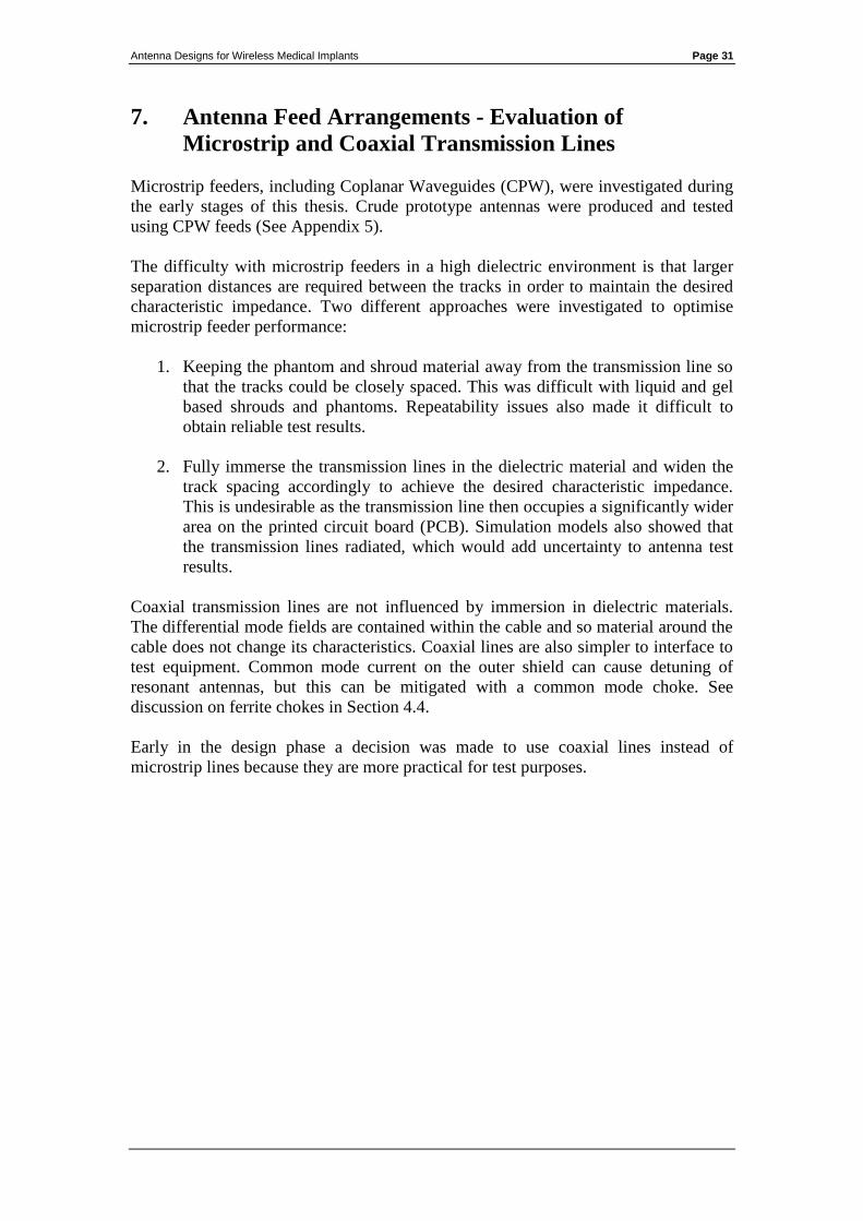
An initial monopole antenna was designed with a ground plane measuring 51 mm x
20 mm on a 0.4 mm thick FR4 substrate. The shield of a rigid 50 Ω coaxial feeder
was bonded directly to the ground plane.
A strait monopole element extended to the end of the substrate, beyond the edge of
the ground plane. The monopole element was fed by the centre conductor of the coax.
The antenna model was surrounded on all sides with a 2 mm thick glycerine dielectric
layer to act as a dielectric shroud. Only the feeder protruded through the glycerine
shroud22
. The model is shown in Figure 17.
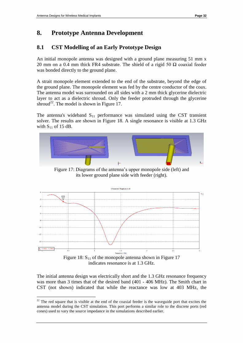
The antenna's wideband S11 performance was simulated using the CST transient
solver. The results are shown in Figure 18. A single resonance is visible at 1.3 GHz
with S11 of 15 dB.
Figure 17: Diagrams of the antenna’s upper monopole side (left) and
its lower ground plane side with feeder (right).
Figure 18: S11 of the monopole antenna shown in Figure 17
indicates resonance is at 1.3 GHz.
The initial antenna design was electrically short and the 1.3 GHz resonance frequency
was more than 3 times that of the desired band (401 - 406 MHz). The Smith chart in
CST (not shown) indicated that while the reactance was low at 403 MHz, the
22
The red square that is visible at the end of the coaxial feeder is the waveguide port that excites the
antenna model during the CST simulation. This port performs a similar role to the discrete ports (red
cones) used to vary the source impedance in the simulations described earlier.
Antenna Designs for Wireless Medical Implants Page 33
radiation resistance of 7.5 Ω was much too low to efficiently match it to a 50 Ω
device. S11 at 403 MHz was only 2.6 dB.
The antenna was electrically lengthened by adding meanders and "capacitive hat"
loading to its monopole element. This was done over 13 different stages, each
comprising a design change and a CST simulation to analyse its effectiveness. The
main changes are summarised below.
In Figure 19 the monopole element was shaped into an inverted-L with a parallel
meander section. This increased the element's physical length from 15.5 mm to 40
mm and reduced its resonant frequency from 1.3 GHz to 676 MHz. The monopole's
protrusion distance beyond the edge of the ground plane was also shortened by 4 mm,
reducing the PCB area required. S11 at 403 MHz was improved by 1.5 dB, but it
remained poor at only 4 dB.
Figure 19: The meandering Inverted-L monopole.
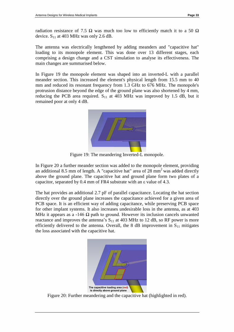
In Figure 20 a further meander section was added to the monopole element, providing
an additional 8.5 mm of length. A "capacitive hat" area of 28 mm2
was added directly
above the ground plane. The capacitive hat and ground plane form two plates of a
capacitor, separated by 0.4 mm of FR4 substrate with an ε value of 4.3.
The hat provides an additional 2.7 pF of parallel capacitance. Locating the hat section
directly over the ground plane increases the capacitance achieved for a given area of
PCB space. It is an efficient way of adding capacitance, while preserving PCB space
for other implant systems. It also increases undesirable loss in the antenna, as at 403
MHz it appears as a -146 Ω path to ground. However its inclusion cancels unwanted
reactance and improves the antenna’s S11 at 403 MHz to 12 dB, so RF power is more
efficiently delivered to the antenna. Overall, the 8 dB improvement in S11 mitigates
the loss associated with the capacitive hat.
Figure 20: Further meandering and the capacitive hat (highlighted in red).

Antenna Designs for Wireless Medical Implants Page 34
The V47 model
In figure 21 a final meander section was added, bringing the resonant frequency to
403 MHz. The full 401 to 406 MHz band has S11 of better than 14 dB. RF current in
the final meander section flows in the opposite direction to the section immediately
before the capacitive hat. This is not good practice in general, as nearby currents
flowing in opposite directions reduce desirable mutual inductance in the antenna
elements and also cause some far field cancellation. However, in this case the parallel
sections are close to the high impedance (open) end of the monopole, where current
flow is reduced. The capacitive hat also ensures that current flow in the final section is
further reduced, mitigating the effect of the opposing currents.
Figure 21: The V47 model used to produce a handmade prototype.
Figure 22: The V47 model with S11 of 14 dB, centred on 403 MHz.
Antenna Designs for Wireless Medical Implants Page 35
8.2 Early Handmade Prototype
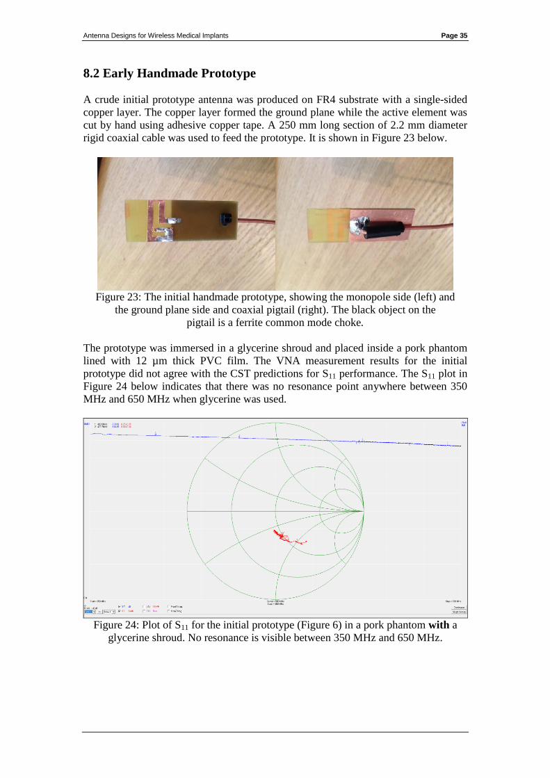
A crude initial prototype antenna was produced on FR4 substrate with a single-sided
copper layer. The copper layer formed the ground plane while the active element was
cut by hand using adhesive copper tape. A 250 mm long section of 2.2 mm diameter
rigid coaxial cable was used to feed the prototype. It is shown in Figure 23 below.
Figure 23: The initial handmade prototype, showing the monopole side (left) and
the ground plane side and coaxial pigtail (right). The black object on the
pigtail is a ferrite common mode choke.
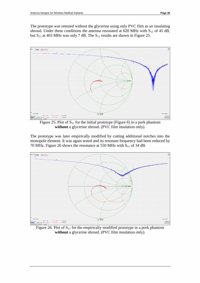
The prototype was immersed in a glycerine shroud and placed inside a pork phantom
lined with 12 µm thick PVC film. The VNA measurement results for the initial
prototype did not agree with the CST predictions for S11 performance. The S11 plot in
Figure 24 below indicates that there was no resonance point anywhere between 350
MHz and 650 MHz when glycerine was used.
Figure 24: Plot of S11 for the initial prototype (Figure 6) in a pork phantom with a
glycerine shroud. No resonance is visible between 350 MHz and 650 MHz.
Antenna Designs for Wireless Medical Implants Page 36
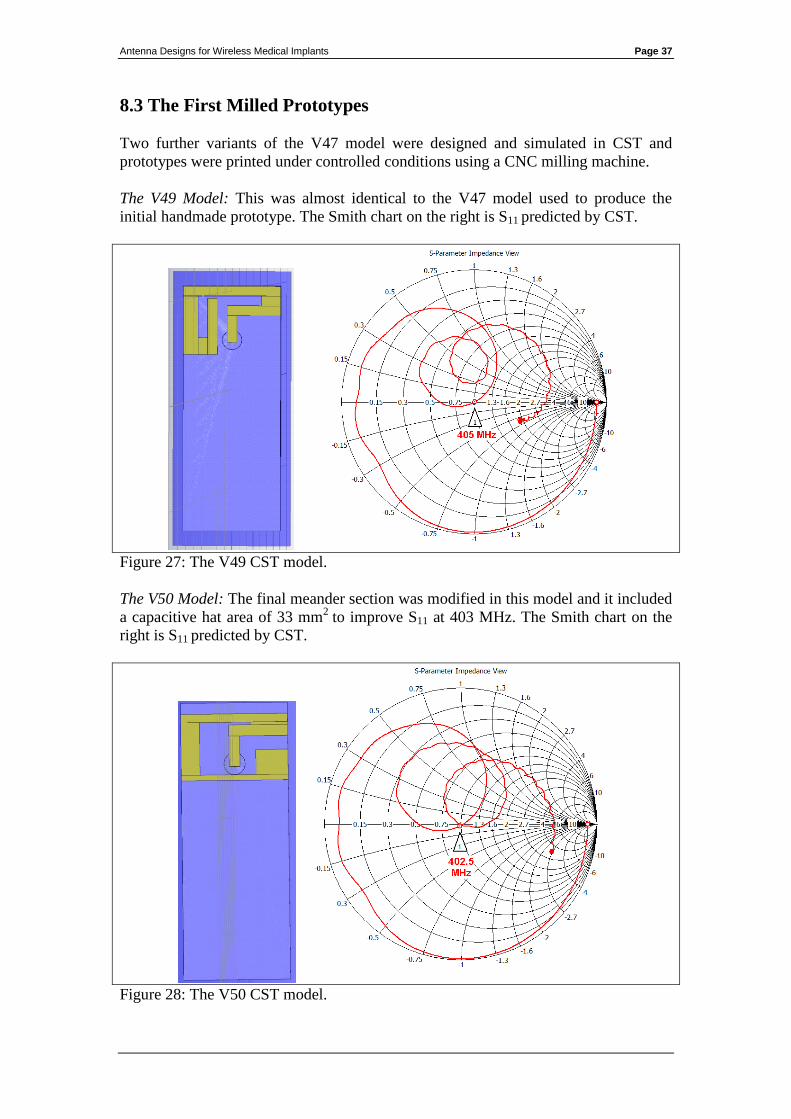
The prototype was retested without the glycerine using only PVC film as an insulating
shroud. Under these conditions the antenna resonated at 620 MHz with S11 of 45 dB,
but S11 at 403 MHz was only 7 dB. The S11 results are shown in Figure 25.
Figure 25: Plot of S11 for the initial prototype (Figure 6) in a pork phantom
without a glycerine shroud. (PVC film insulation only).
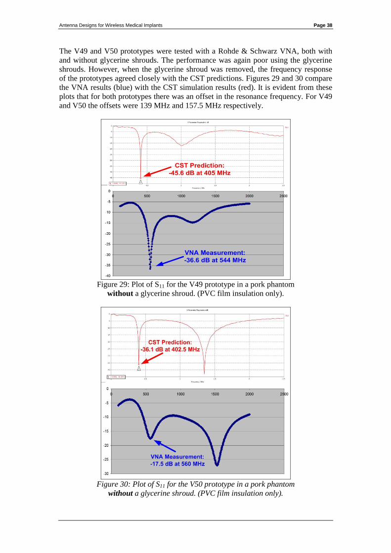
The prototype was later empirically modified by cutting additional notches into the
monopole element. It was again tested and its resonant frequency had been reduced by
70 MHz. Figure 26 shows the resonance at 550 MHz with S11 of 34 dB.
Figure 26: Plot of S11 for the empirically modified prototype in a pork phantom
without a glycerine shroud. (PVC film insulation only).
Antenna Designs for Wireless Medical Implants Page 37
8.3 The First Milled Prototypes
Two further variants of the V47 model were designed and simulated in CST and
prototypes were printed under controlled conditions using a CNC milling machine.
The V49 Model: This was almost identical to the V47 model used to produce the
initial handmade prototype. The Smith chart on the right is S11 predicted by CST.
Figure 27: The V49 CST model.
The V50 Model: The final meander section was modified in this model and it included
a capacitive hat area of 33 mm2
to improve S11 at 403 MHz. The Smith chart on the
right is S11 predicted by CST.
Figure 28: The V50 CST model.
Antenna Designs for Wireless Medical Implants Page 38
The V49 and V50 prototypes were tested with a Rohde & Schwarz VNA, both with
and without glycerine shrouds. The performance was again poor using the glycerine
shrouds. However, when the glycerine shroud was removed, the frequency response
of the prototypes agreed closely with the CST predictions. Figures 29 and 30 compare
the VNA results (blue) with the CST simulation results (red). It is evident from these
plots that for both prototypes there was an offset in the resonance frequency. For V49
and V50 the offsets were 139 MHz and 157.5 MHz respectively.
Figure 29: Plot of S11 for the V49 prototype in a pork phantom
without a glycerine shroud. (PVC film insulation only).
Figure 30: Plot of S11 for the V50 prototype in a pork phantom
without a glycerine shroud. (PVC film insulation only).

Antenna Designs for Wireless Medical Implants Page 39
8.4 Analysis of Unexpected Measurement Results
Figures 29 and 30 in the previous section highlight the difference between the
resonant frequencies predicted by the transient solver in CST and that of the
prototypes when measured with the VNA. This frequency discrepancy affected both
of the milled antenna designs. The previous handmade prototypes, albeit produced
under less controlled conditions, also resonated at higher frequencies than predicted.
This deviation from the predictions warranted further analysis.
There were a number of possible sources of error that were suspected of contributing
to the frequency offset. These were:
Variations between the dielectric properties of the phantom tissue used in the
simulations and that used in the VNA testing.
The effect of common mode current flowing on the outside of the coaxial
feeder.
Errors in the configuration of the CST simulation.
Appendix 3 presents the full results of further CST simulations that were run to
determine if the 3 above factors were causing the frequency deviation.
The conclusions drawn from these investigations were as follows:
Investigation 1 - The impact of variations in the phantom material and its effect on
antenna resonant frequency.
The V49 antenna model was simulated with 5 different phantom material types. Plain
tap water and 4 different body tissue types (skin, brain, bone and fat) were selected to
provide a diverse range of electrical characteristics in the simulations. The resulting
S11 frequency response plots are presented in Appendix 3, and summarised below in
Table 1 along with the phantom material characteristics used in each simulation. The
impact on the antenna's resonant frequency is also listed.
Phantom
material
Dielectric
constant
(Epsilon)
Magnetic
permeability
(Mue)
Electrical
conductivity
Antenna
resonance
frequency
Deviation
from
405 MHz
Skin 31.29 1 8.0138 S/m 405 MHz 0 MHz
Brain 38.111 1 10.31 S/m 405 MHz 0 MHz
Bone 12.66 1 3.8591 S/m 418 MHz + 13 MHz
Tap Water 78 0.999991 1.59 S/m 437 MHz + 32 MHz
Fat 4.6 1 0.58521 S/m 524 MHz + 119 MHz
Table 1: The effect of various phantom materials on antenna resonant frequency.
Despite the diverse characteristics of the phantom materials used, none of the
simulations resulted in frequency deviations similar to that observed during the VNA
measurements23
. Fat tissue, which caused the greatest deviation, is a statistical outlier.
23
For V49 and V50 the frequency discrepancies were 139 MHz and 157.5 MHz respectively.
Antenna Designs for Wireless Medical Implants Page 40
Its low water content gives it a very low dielectric constant with respect to other body
tissues. Even tap water produced a deviation of only 20% to 25% the size of the
measured offset in the VNA tests.
After considering these results, phantom material variation was dismissed as a cause
of the measured frequency offset.
Investigation 2 - The effects of common mode current on the coaxial feeder.
Two different versions of the V49 model were simulated in CST with differing
lengths of coaxial feeder (4 mm and 125 mm). The results are also presented in
Appendix 3. While the extra coax did introduce additional loss, with a consequent
increase of wideband return loss, it did not change the resonance frequency. It was
also noted during the VNA measurements, that moving the ferrite choke along the
length of the feeder had no noticeable impact on the antenna's resonant frequency. For
these reasons the coaxial feeder was eliminated as a possible cause of the frequency
offset.
Investigation 3 - Agreement between free space S11 predictions and measurements.
The S11 performance of the V49 model in free space was simulated and measured.
Close agreement between the free space prediction data and measurements indicated
that the CST tool is correctly configured. At higher frequencies there was a 2 dB
return loss difference between the prediction and measurement data, however this can
be explained by the higher insertion loss of the 15 cm thin coax feeder on the
prototype. The CST model has a shorter feeder with a lower insertion loss. As a result
of this exercise, errors in the construction of the CST antenna models were eliminated
as a possible cause of the discrepancy.
Investigation 4 - Review of suitability of glycerine as a dielectric loading material.
The literature suggests that a layer of glycerine surrounding the antenna aids dielectric
loading of the antenna and impedance matching to the surrounding high dielectric
tissue [1]. The results of prototype tests so far indicated that this was not the case.
In order to determine if a glycerine shroud was necessary, two simulations were run,
with and without a glycerine shroud. Both simulations use the same antenna and the
same phantom. It was noted that there is only a 2 dB difference in radiation to the far
field, and the model with the glycerine shroud had the greater loss. The results of the
simulations are presented in Appendix 3.
Antenna Designs for Wireless Medical Implants Page 41
8.5 Changes to the Research Methodology Arising from These
Investigations
Using simulation software
The results of the investigation did not identify the cause of the frequency offset
observed between the CST simulations and the VNA measurements. It was felt that it
would be imprudent to continue adding further design refinements to simulation
models which have unexplained variations in their results.
It was instead decided to further develop the prototypes empirically without the use of
simulation software. Once antenna prototypes had been tested and validated, the
designs could then be simulated again in CST. This would allow the simulation
predictions to be reconciled with measurement results and to identify the cause of the
frequency offset.
Review of glycerine as a shroud material
The early prototypes used glycerine which is marketed as a food additive, and its
manufacturer claims that it contained no other substances. Nevertheless, although
glycerine was suggested [1] as a low loss, high dielectric material suitable for
shrouding, it had performed poorly in the measurement results so far.
PVC film provided promising results in some of the tests, but it inevitably traps small
air pockets which lowered the dielectric constant in the antenna’s near field. This
caused the antenna’s performance to vary depending on the pressure applied to it.
Liquid or gel based shroud materials do have an advantage over PVC film in this
regard, as the antenna can be fully immersed in the liquid without trapping any air.
The problem of trapped air was resolved by coating the prototypes in a thin layer of
epoxy resin instead of PVC film and allowing it time to cure. Cured epoxy resin has a
dielectric constant of 3.6 which is similar to that of PVC (3.4). This fully sealed the
prototypes and prevented phantom material ingress.
It was decided not to use glycerine as an insulating shroud material in subsequent
prototype designs and instead to encapsulate them in epoxy resin.
Review of artificial phantoms
Earlier prototypes were tested in phantoms made using fresh meat products (pork and
chicken), or in some cases, hands clasped around an insulated antenna for proof of
concept. However it proved difficult to maintain a controlled test environment using
these methods.
When hands are used as a phantom small air gaps are trapped close to the antenna.
Tests showed the antenna’s frequency response and S11 to be highly sensitive to the
pressure applied. Repeatability was very poor with this approach.
Antenna Designs for Wireless Medical Implants Page 42
It is also difficult to control for such variation using meat products as a phantom. It is
difficult to fully surround the antenna with meat so its performance is also sensitive to
the pressure applied. Moreover, the characteristics of meat changes over time. These
changes influence the prototype’s performance and impair the repeatability of the test
results. The meat did not have to spoil or dry out for there to be a noticeable effect on
how it dielectrically loaded an antenna. Often there is no way to know how long a
meat product has been on sale, and there were differences between some of the
samples purchased for the tests.
It was decided to avoid using meat products and to use an artificial liquid based
phantom in order to improve the repeatability of the test results. A phantom composed
of de-ionised water, sugar, salt and HEC was selected. The recipe was taken from
“Simulated biological materials for electromagnetic radiation absorption” by G
Hartsgrove, A Kraszewski, A Surowiec - Bioelectromagnetics, 1987. The
characteristics are described as dielectric constant of 49, mue of 1 and electrical
conductivity of 0.6 S/m.
8.6 Empirical Retuning of Prototype Antennas.
The two milled prototypes were empirically retuned in order to bring their resonances
from 544 MHz (V49 model) and 560 MHz (V50 model) down to the desired band of
401 – 406 MHz.
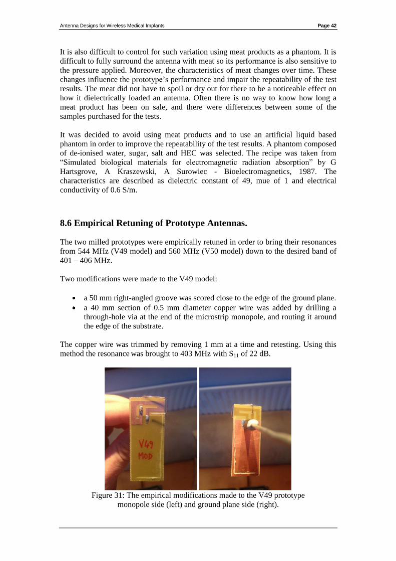
Two modifications were made to the V49 model:
a 50 mm right-angled groove was scored close to the edge of the ground plane.
a 40 mm section of 0.5 mm diameter copper wire was added by drilling a
through-hole via at the end of the microstrip monopole, and routing it around
the edge of the substrate.
The copper wire was trimmed by removing 1 mm at a time and retesting. Using this
method the resonance was brought to 403 MHz with S11 of 22 dB.
Figure 31: The empirical modifications made to the V49 prototype
monopole side (left) and ground plane side (right).
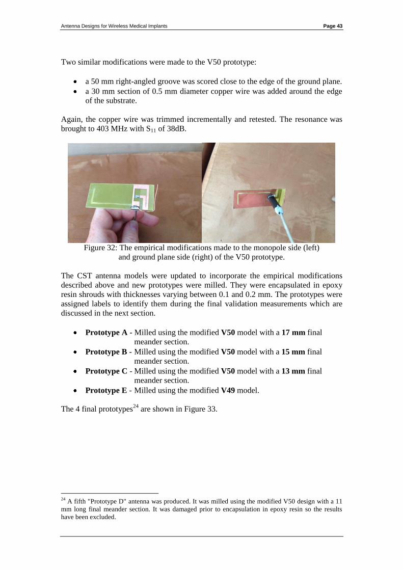
Antenna Designs for Wireless Medical Implants Page 43
Two similar modifications were made to the V50 prototype:
a 50 mm right-angled groove was scored close to the edge of the ground plane.
a 30 mm section of 0.5 mm diameter copper wire was added around the edge
of the substrate.
Again, the copper wire was trimmed incrementally and retested. The resonance was
brought to 403 MHz with S11 of 38dB.
Figure 32: The empirical modifications made to the monopole side (left)
and ground plane side (right) of the V50 prototype.
The CST antenna models were updated to incorporate the empirical modifications
described above and new prototypes were milled. They were encapsulated in epoxy
resin shrouds with thicknesses varying between 0.1 and 0.2 mm. The prototypes were
assigned labels to identify them during the final validation measurements which are
discussed in the next section.
Prototype A - Milled using the modified V50 model with a 17 mm final
meander section.
Prototype B - Milled using the modified V50 model with a 15 mm final
meander section.
Prototype C - Milled using the modified V50 model with a 13 mm final
meander section.
Prototype E - Milled using the modified V49 model.
The 4 final prototypes24
are shown in Figure 33.
24
A fifth "Prototype D" antenna was produced. It was milled using the modified V50 design with a 11
mm long final meander section. It was damaged prior to encapsulation in epoxy resin so the results
have been excluded.
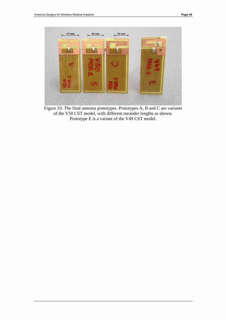
Antenna Designs for Wireless Medical Implants Page 44
Figure 33: The final antenna prototypes. Prototypes A, B and C are variants
of the V50 CST model, with different meander lengths as shown.
Prototype E is a variant of the V49 CST model.
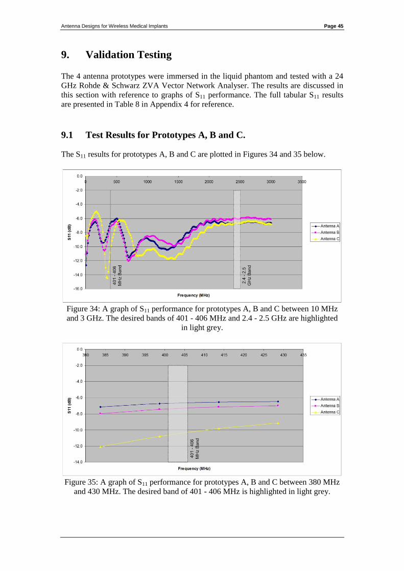
Antenna Designs for Wireless Medical Implants Page 45
9. Validation Testing
The 4 antenna prototypes were immersed in the liquid phantom and tested with a 24
GHz Rohde & Schwarz ZVA Vector Network Analyser. The results are discussed in
this section with reference to graphs of S11 performance. The full tabular S11 results
are presented in Table 8 in Appendix 4 for reference.
9.1 Test Results for Prototypes A, B and C.
The S11 results for prototypes A, B and C are plotted in Figures 34 and 35 below.
Figure 34: A graph of S11 performance for prototypes A, B and C between 10 MHz
and 3 GHz. The desired bands of 401 - 406 MHz and 2.4 - 2.5 GHz are highlighted
in light grey.
Figure 35: A graph of S11 performance for prototypes A, B and C between 380 MHz
and 430 MHz. The desired band of 401 - 406 MHz is highlighted in light grey.
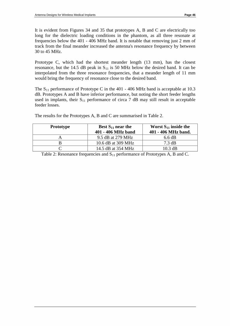
Antenna Designs for Wireless Medical Implants Page 46
It is evident from Figures 34 and 35 that prototypes A, B and C are electrically too
long for the dielectric loading conditions in the phantom, as all three resonate at
frequencies below the 401 - 406 MHz band. It is notable that removing just 2 mm of
track from the final meander increased the antenna's resonance frequency by between
30 to 45 MHz.
Prototype C, which had the shortest meander length (13 mm), has the closest
resonance, but the 14.5 dB peak in S11 is 50 MHz below the desired band. It can be
interpolated from the three resonance frequencies, that a meander length of 11 mm
would bring the frequency of resonance close to the desired band.
The S11 performance of Prototype C in the 401 - 406 MHz band is acceptable at 10.3
dB. Prototypes A and B have inferior performance, but noting the short feeder lengths
used in implants, their S11 performance of circa 7 dB may still result in acceptable
feeder losses.
The results for the Prototypes A, B and C are summarised in Table 2.
Prototype Best S11 near the
401 - 406 MHz band
Worst S11 inside the
401 - 406 MHz band.
A 9.5 dB at 279 MHz 6.6 dB
B 10.6 dB at 309 MHz 7.3 dB
C 14.5 dB at 354 MHz 10.3 dB
Table 2: Resonance frequencies and S11 performance of Prototypes A, B and C.
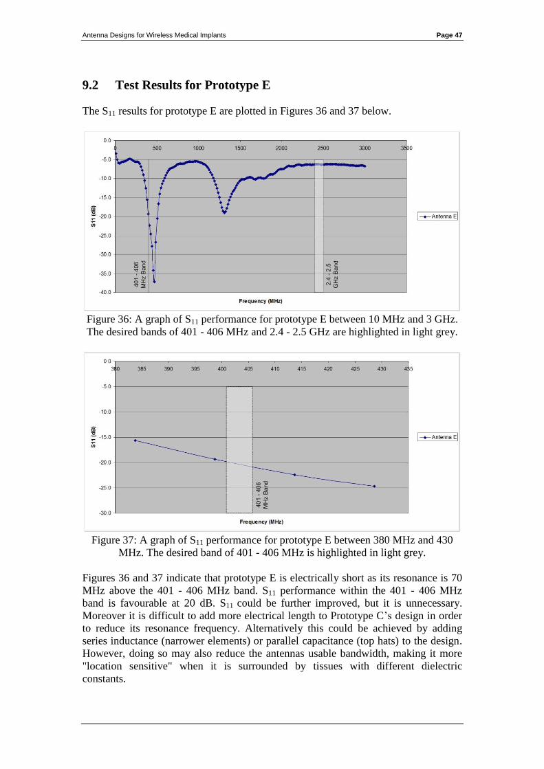
Antenna Designs for Wireless Medical Implants Page 47
9.2 Test Results for Prototype E
The S11 results for prototype E are plotted in Figures 36 and 37 below.
Figure 36: A graph of S11 performance for prototype E between 10 MHz and 3 GHz.
The desired bands of 401 - 406 MHz and 2.4 - 2.5 GHz are highlighted in light grey.
Figure 37: A graph of S11 performance for prototype E between 380 MHz and 430
MHz. The desired band of 401 - 406 MHz is highlighted in light grey.
Figures 36 and 37 indicate that prototype E is electrically short as its resonance is 70
MHz above the 401 - 406 MHz band. S11 performance within the 401 - 406 MHz
band is favourable at 20 dB. S11 could be further improved, but it is unnecessary.
Moreover it is difficult to add more electrical length to Prototype C’s design in order
to reduce its resonance frequency. Alternatively this could be achieved by adding
series inductance (narrower elements) or parallel capacitance (top hats) to the design.
However, doing so may also reduce the antennas usable bandwidth, making it more
"location sensitive" when it is surrounded by tissues with different dielectric
constants.

Antenna Designs for Wireless Medical Implants Page 48
The results for Prototype E are summarised in Table 3.
Prototype Best S11 close to the
401 - 406 MHz band
S11 within the
401 - 406 MHz band.
E 37.2 dB at 473 MHz 20 dB
Table 3: Resonance frequency and S11 performance of Prototype E.
9.3 Conclusions on the Validation Test Results
The antenna designs provided good results overall, achieving S11 of 10 dB to 20 dB in
the 401 – 406 MHz band.
The resonant frequencies of the 4 prototypes varied widely25
. This was not related to
the simulation software issue described in Section 8.
The prototypes were based on a preceding generation of empirical tuned antennas.
Light materials, such as 0.5 mm diameter copper wire, were used to tune them. These
materials are not robust and they do not hold their shape with respect to the small
tolerances at play. The test results showed that a difference of just 2 mm in the
antenna’s dimensions produce changes as large as 45 MHz in its resonant frequency.
It is likely that the reduced wavelength in the dielectric phantom, which is just 15 –
20% that of free space, multiplied the impact of minor physical changes.
In the absence of reliable simulations, the empirical approach also proved effective,
however repeatability was poor.
25
Resonant frequencies ranged between 279 MHz and 473 MHz.
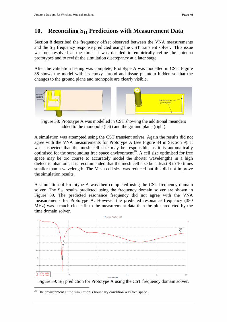
Antenna Designs for Wireless Medical Implants Page 49
10. Reconciling S11 Predictions with Measurement Data
Section 8 described the frequency offset observed between the VNA measurements
and the S11 frequency response predicted using the CST transient solver. This issue
was not resolved at the time. It was decided to empirically refine the antenna
prototypes and to revisit the simulation discrepancy at a later stage.
After the validation testing was complete, Prototype A was modelled in CST. Figure
38 shows the model with its epoxy shroud and tissue phantom hidden so that the
changes to the ground plane and monopole are clearly visible.
Figure 38: Prototype A was modelled in CST showing the additional meanders
added to the monopole (left) and the ground plane (right).
A simulation was attempted using the CST transient solver. Again the results did not
agree with the VNA measurements for Prototype A (see Figure 34 in Section 9). It
was suspected that the mesh cell size may be responsible, as it is automatically
optimised for the surrounding free space environment26
. A cell size optimised for free
space may be too coarse to accurately model the shorter wavelengths in a high
dielectric phantom. It is recommended that the mesh cell size be at least 8 to 10 times
smaller than a wavelength. The Mesh cell size was reduced but this did not improve
the simulation results.
A simulation of Prototype A was then completed using the CST frequency domain
solver. The S11 results predicted using the frequency domain solver are shown in
Figure 39. The predicted resonance frequency did not agree with the VNA
measurements for Prototype A. However the predicted resonance frequency (380
MHz) was a much closer fit to the measurement data than the plot predicted by the
time domain solver.
Figure 39: S11 prediction for Prototype A using the CST frequency domain solver.
26
The environment at the simulation’s boundary condition was free space.
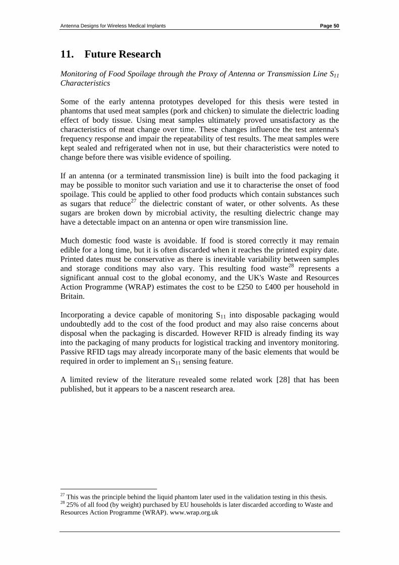
Antenna Designs for Wireless Medical Implants Page 50
11. Future Research
Monitoring of Food Spoilage through the Proxy of Antenna or Transmission Line S11
Characteristics
Some of the early antenna prototypes developed for this thesis were tested in
phantoms that used meat samples (pork and chicken) to simulate the dielectric loading
effect of body tissue. Using meat samples ultimately proved unsatisfactory as the
characteristics of meat change over time. These changes influence the test antenna's
frequency response and impair the repeatability of test results. The meat samples were
kept sealed and refrigerated when not in use, but their characteristics were noted to
change before there was visible evidence of spoiling.
If an antenna (or a terminated transmission line) is built into the food packaging it
may be possible to monitor such variation and use it to characterise the onset of food
spoilage. This could be applied to other food products which contain substances such
as sugars that reduce27
the dielectric constant of water, or other solvents. As these
sugars are broken down by microbial activity, the resulting dielectric change may
have a detectable impact on an antenna or open wire transmission line.
Much domestic food waste is avoidable. If food is stored correctly it may remain
edible for a long time, but it is often discarded when it reaches the printed expiry date.
Printed dates must be conservative as there is inevitable variability between samples
and storage conditions may also vary. This resulting food waste28
represents a
significant annual cost to the global economy, and the UK's Waste and Resources
Action Programme (WRAP) estimates the cost to be £250 to £400 per household in
Britain.
Incorporating a device capable of monitoring S11 into disposable packaging would
undoubtedly add to the cost of the food product and may also raise concerns about
disposal when the packaging is discarded. However RFID is already finding its way
into the packaging of many products for logistical tracking and inventory monitoring.
Passive RFID tags may already incorporate many of the basic elements that would be
required in order to implement an S11 sensing feature.
A limited review of the literature revealed some related work [28] that has been
published, but it appears to be a nascent research area.
27
This was the principle behind the liquid phantom later used in the validation testing in this thesis. 28
25% of all food (by weight) purchased by EU households is later discarded according to Waste and
Resources Action Programme (WRAP). www.wrap.org.uk

Antenna Designs for Wireless Medical Implants Page 51
12. References and Bibliography
[1] Dielectric Loaded Impedance Matching for Wideband Implanted Antennas:
Dissanayake, Esselle and Yuce.
[2] An Ultra-low Power CMOS RF Transceiver for Medical Implants:
Bohorquez, Dawson and Chandrakasan.
[3] Electromagnetic Interactions between Biological Tissues and Implantable
Biotelemetry Systems:
Kim and Rahmat-Samii.
[4] Compilation of the Dielectric Properties of Body Tissues at RF and Microwave
Frequencies:
C. Gabriel and S. Gabriel.
[5] ICT implants in the human body: A review:
Fabienne Nsanze 21st December 2004
[6] Developing New Medical Implants and Diagnostic Equipment:
Hodgins, Bertsch, Post, Frischholz, Volckaerts, Spensley, Wasikiewicz, Higgins, Von
Stetten and Kenney
[7] A Miniature Implanted Inverted-F Antenna for GPS Application:
Azad and Ali.
[8] Wireless Telemetry for Electronic Pill Technology:
Yuce, Dissanayake, Keong.
[9] Body Implant Communication – Is it a reality?
Henry Higgins.
[10] Body EMF Absorption: A Design Issue for Implantable Medical Electronics:
Qiang Fang.
[11] Impact of an Aortic Valve Implant on Body Surface UWB Propagation: A
Preliminary Study:
Yang, Sayrafian-Pour, Hagedorn, Terrill, Yazdandoost, Taparugssanagorn,
Hämäläinen and Iinatti.
[12] Wireless Power Technology for Boiomedical Implants:
Laskovsky, Dissanayake and Yuce.
[13] Mixed-Signal Integrated Circuits for Self-Contained Sub-Cubic Millimeter
Biomedical Implants:
Chow, Chakraborty, Chappell and Irazoqui.
[14] Wireless Body Sensor Network using Medical Implant Band:
Yuce, Myo, Khan and Liu.

Antenna Designs for Wireless Medical Implants Page 52
[15] Monitoring of Physiological Parameters from Multiple Patients Using Wireless
Sensor Network:
Yuce, Choong and Khan.
[16] Wireless Communications Technology in Telehealth Systems:
Kailas and Ingram.
[17] A Review of Implantable Patch Antennas for Biomedical Telemetry: Challenges
and Solutions:
Kiourti and Nikita.
[18] Detuning Issues and Performance of a Novel Implantable Antenna for Telemetry
Applications:
Kiourti and Nikita.
[19] Radiation Characteristics of Loop Antennas for Biomedical Implants:
Abdelsayed, Nikolova and Jamal Deen.
[20] Design, Realization and Measurements of a Miniature Antenna for Implantable
Wireless Communication Systems:
Merli, Bolomey, Zürcher, Corradini, Meurville and Skrivervik.
[21] The Effect of Insulating Layers on the Performance of Implanted Antennas:
Merli, Fuchs, Mosig and Skrivervik.
[22] Ultra Wideband Wireless Body Area Network for Medical Applications:
Balasingham, Chávez-Santiago, Bergsland, Ramstad and Fosse1.
[23] Design Strategies for Implantable Antennas:
Skrivervik and Merli.
[24] Radio System Design for Telecommunications. Second Edition:
Roger Freeman.
[25] Simulated biological materials for electromagnetic radiation absorption -
Bioelectromagnetics, 1987” by G Hartsgrove, A Kraszewski, A Surowiec
[26] Biostability and corrosion resistance of a biocompatible encapsulation and
interconnect technology for implantable electronics: Maaike Op de Beeck, Karen
Qian, Karl Malachowski, Bishoy Morcos, Alex Radisic, Chris Van Hoof
[27] The Handbook of Dielectric and Thermal Properties of Materials at Microwave
Frequencies: Vyacheslav V. Komarov
[28] Silk-Based Conformal, Adhesive, Edible Food Sensors: Hu Tao, Mark A.
Brenckle, Miaomiao Yang, Jingdi Zhang, Mengkun Liu, Sean M. Siebert, Richard D.
Averitt, Manu S. Mannoor, Michael C. McAlpine, John A. Rogers, David L. Kaplan,
and Fiorenzo G. Omenetto
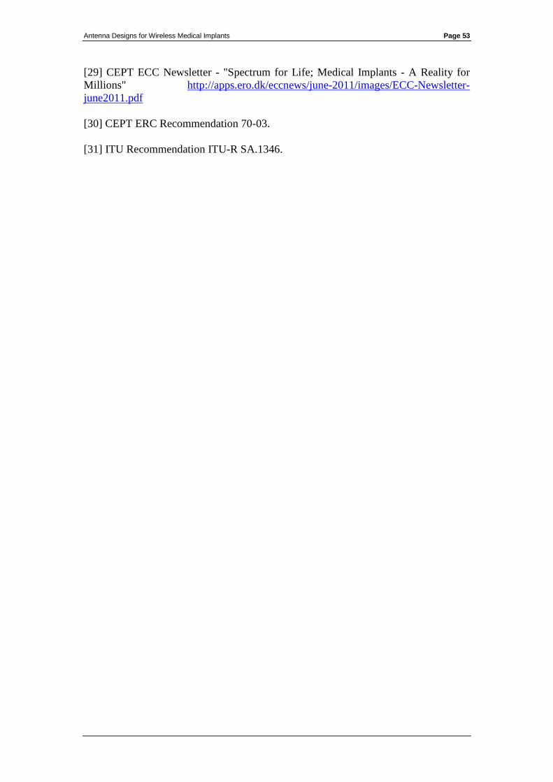
Antenna Designs for Wireless Medical Implants Page 53
[29] CEPT ECC Newsletter - "Spectrum for Life; Medical Implants - A Reality for
Millions" http://apps.ero.dk/eccnews/june-2011/images/ECC-Newsletter-
june2011.pdf
[30] CEPT ERC Recommendation 70-03.
[31] ITU Recommendation ITU-R SA.1346.
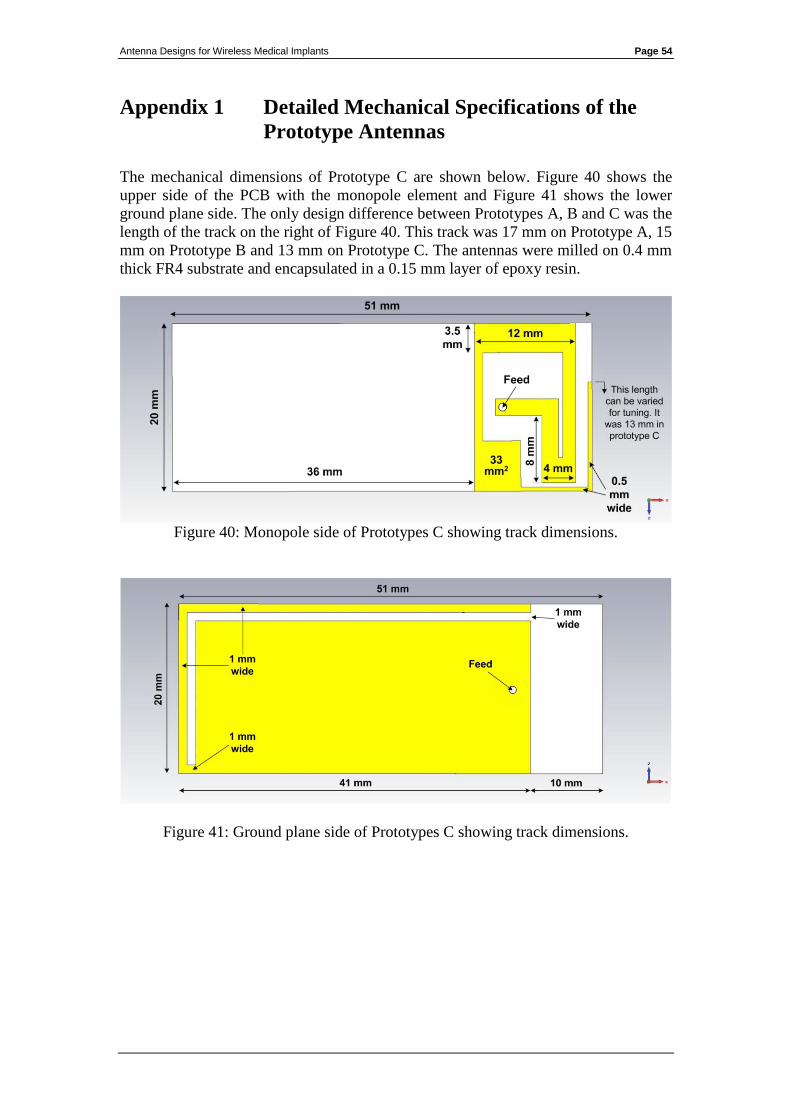
Antenna Designs for Wireless Medical Implants Page 54
Appendix 1 Detailed Mechanical Specifications of the
Prototype Antennas
The mechanical dimensions of Prototype C are shown below. Figure 40 shows the
upper side of the PCB with the monopole element and Figure 41 shows the lower
ground plane side. The only design difference between Prototypes A, B and C was the
length of the track on the right of Figure 40. This track was 17 mm on Prototype A, 15
mm on Prototype B and 13 mm on Prototype C. The antennas were milled on 0.4 mm
thick FR4 substrate and encapsulated in a 0.15 mm layer of epoxy resin.
Figure 40: Monopole side of Prototypes C showing track dimensions.
Figure 41: Ground plane side of Prototypes C showing track dimensions.
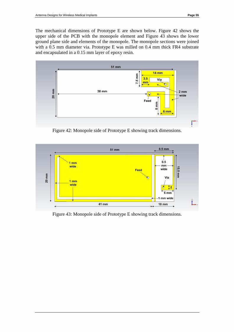
Antenna Designs for Wireless Medical Implants Page 55
The mechanical dimensions of Prototype E are shown below. Figure 42 shows the
upper side of the PCB with the monopole element and Figure 43 shows the lower
ground plane side and elements of the monopole. The monopole sections were joined
with a 0.5 mm diameter via. Prototype E was milled on 0.4 mm thick FR4 substrate
and encapsulated in a 0.15 mm layer of epoxy resin.
Figure 42: Monopole side of Prototype E showing track dimensions.
Figure 43: Monopole side of Prototype E showing track dimensions.
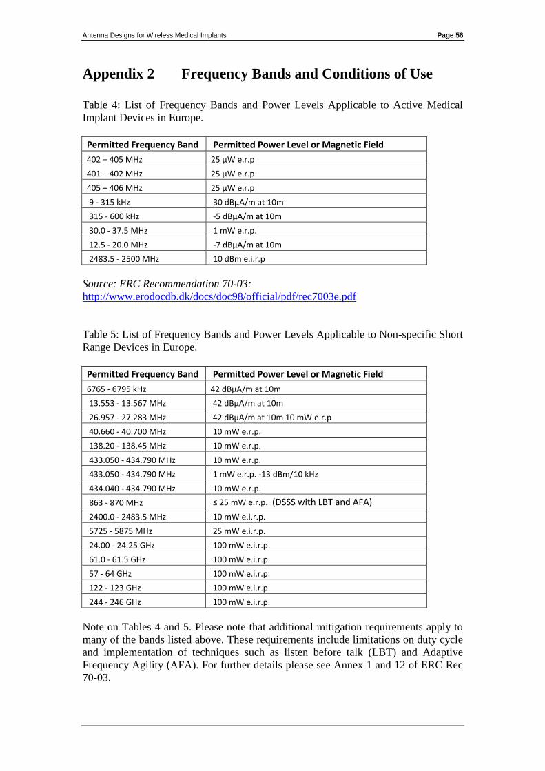
Antenna Designs for Wireless Medical Implants Page 56
Appendix 2 Frequency Bands and Conditions of Use
Table 4: List of Frequency Bands and Power Levels Applicable to Active Medical
Implant Devices in Europe.
Permitted Frequency Band Permitted Power Level or Magnetic Field
402 – 405 MHz 25 μW e.r.p
401 – 402 MHz 25 μW e.r.p
405 – 406 MHz 25 μW e.r.p
9 - 315 kHz 30 dBμA/m at 10m
315 - 600 kHz -5 dBμA/m at 10m
30.0 - 37.5 MHz 1 mW e.r.p.
12.5 - 20.0 MHz -7 dBμA/m at 10m
2483.5 - 2500 MHz 10 dBm e.i.r.p
Source: ERC Recommendation 70-03:
http://www.erodocdb.dk/docs/doc98/official/pdf/rec7003e.pdf
Table 5: List of Frequency Bands and Power Levels Applicable to Non-specific Short
Range Devices in Europe.
Permitted Frequency Band Permitted Power Level or Magnetic Field
6765 - 6795 kHz 42 dBμA/m at 10m
13.553 - 13.567 MHz 42 dBμA/m at 10m
26.957 - 27.283 MHz 42 dBμA/m at 10m 10 mW e.r.p
40.660 - 40.700 MHz 10 mW e.r.p.
138.20 - 138.45 MHz 10 mW e.r.p.
433.050 - 434.790 MHz 10 mW e.r.p.
433.050 - 434.790 MHz 1 mW e.r.p. -13 dBm/10 kHz
434.040 - 434.790 MHz 10 mW e.r.p.
863 - 870 MHz ≤ 25 mW e.r.p. (DSSS with LBT and AFA)
2400.0 - 2483.5 MHz 10 mW e.i.r.p.
5725 - 5875 MHz 25 mW e.i.r.p.
24.00 - 24.25 GHz 100 mW e.i.r.p.
61.0 - 61.5 GHz 100 mW e.i.r.p.
57 - 64 GHz 100 mW e.i.r.p.
122 - 123 GHz 100 mW e.i.r.p.
244 - 246 GHz 100 mW e.i.r.p.
Note on Tables 4 and 5. Please note that additional mitigation requirements apply to
many of the bands listed above. These requirements include limitations on duty cycle
and implementation of techniques such as listen before talk (LBT) and Adaptive
Frequency Agility (AFA). For further details please see Annex 1 and 12 of ERC Rec
70-03.

Antenna Designs for Wireless Medical Implants Page 57
Source: ERC Recommendation 70-03:
http://www.erodocdb.dk/docs/doc98/official/pdf/rec7003e.pdf
Table 6: List of Frequency Bands and Permitted Channel Bandwidths Applicable to
Active Medical Implant Devices in the United States.
Permitted Frequency Band Permitted Bandwidth
401 - 401.85 MHz 100 kHz
401.85 - 402 MHz 150 kHz
402 - 405 MHz 300 kHz
405 - 406 MHz 100 kHz
413 - 419 MHz 6 MHz
426 - 432 MHz 6 MHz
438 - 444 MHz 6 MHz
451 - 457 MHz 6 MHz
Source:
http://www.fcc.gov/encyclopedia/medical-device-radiocommunications-service-
medradio
Table 7: List of frequency bands identified for use by Industrial, Scientific and
Medical Applications in the United States.
Permitted Frequency Band
6.765 - 6.795 MHz
13.553 - 13.567 MHz
26.957 - 27.283 MHz
40.660 - 40.700 MHz
433.050 - 434.790 MHz
902.000 - 928.000 MHz
2400 - 2500 MHz
5.725 - 5.875 GHz
24.000 - 24.250 GHz
61.000 - 61.500 GHz
122.000 - 123.000 GHz
244.000 - 246.000 GHz
Source:
http://www.gpo.gov/fdsys/pkg/CFR-2007-title47-vol1/pdf/CFR-2007-title47-vol1-
part18.pdf
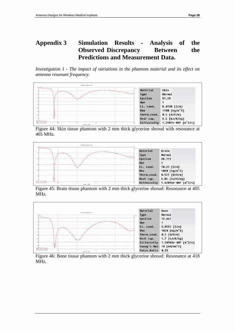
Antenna Designs for Wireless Medical Implants Page 58
Appendix 3 Simulation Results - Analysis of the
Observed Discrepancy Between the
Predictions and Measurement Data.
Investigation 1 - The impact of variations in the phantom material and its effect on
antenna resonant frequency.
Figure 44: Skin tissue phantom with 2 mm thick glycerine shroud with resonance at
405 MHz.
Figure 45: Brain tissue phantom with 2 mm thick glycerine shroud: Resonance at 405
MHz.
Figure 46: Bone tissue phantom with 2 mm thick glycerine shroud: Resonance at 418
MHz.
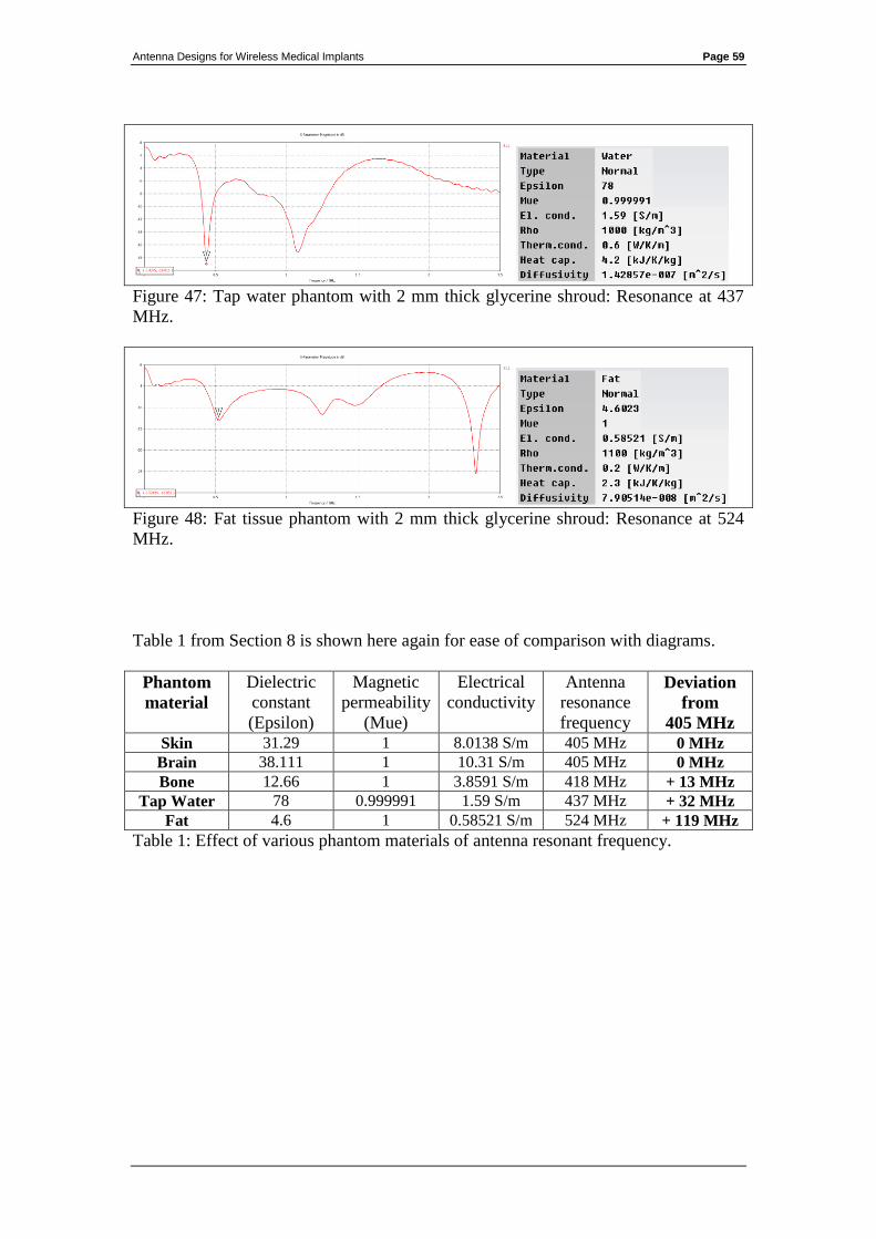
Antenna Designs for Wireless Medical Implants Page 59
Figure 47: Tap water phantom with 2 mm thick glycerine shroud: Resonance at 437
MHz.
Figure 48: Fat tissue phantom with 2 mm thick glycerine shroud: Resonance at 524
MHz.
Table 1 from Section 8 is shown here again for ease of comparison with diagrams.
Phantom
material
Dielectric
constant
(Epsilon)
Magnetic
permeability
(Mue)
Electrical
conductivity
Antenna
resonance
frequency
Deviation
from
405 MHz
Skin 31.29 1 8.0138 S/m 405 MHz 0 MHz
Brain 38.111 1 10.31 S/m 405 MHz 0 MHz
Bone 12.66 1 3.8591 S/m 418 MHz + 13 MHz
Tap Water 78 0.999991 1.59 S/m 437 MHz + 32 MHz
Fat 4.6 1 0.58521 S/m 524 MHz + 119 MHz
Table 1: Effect of various phantom materials of antenna resonant frequency.
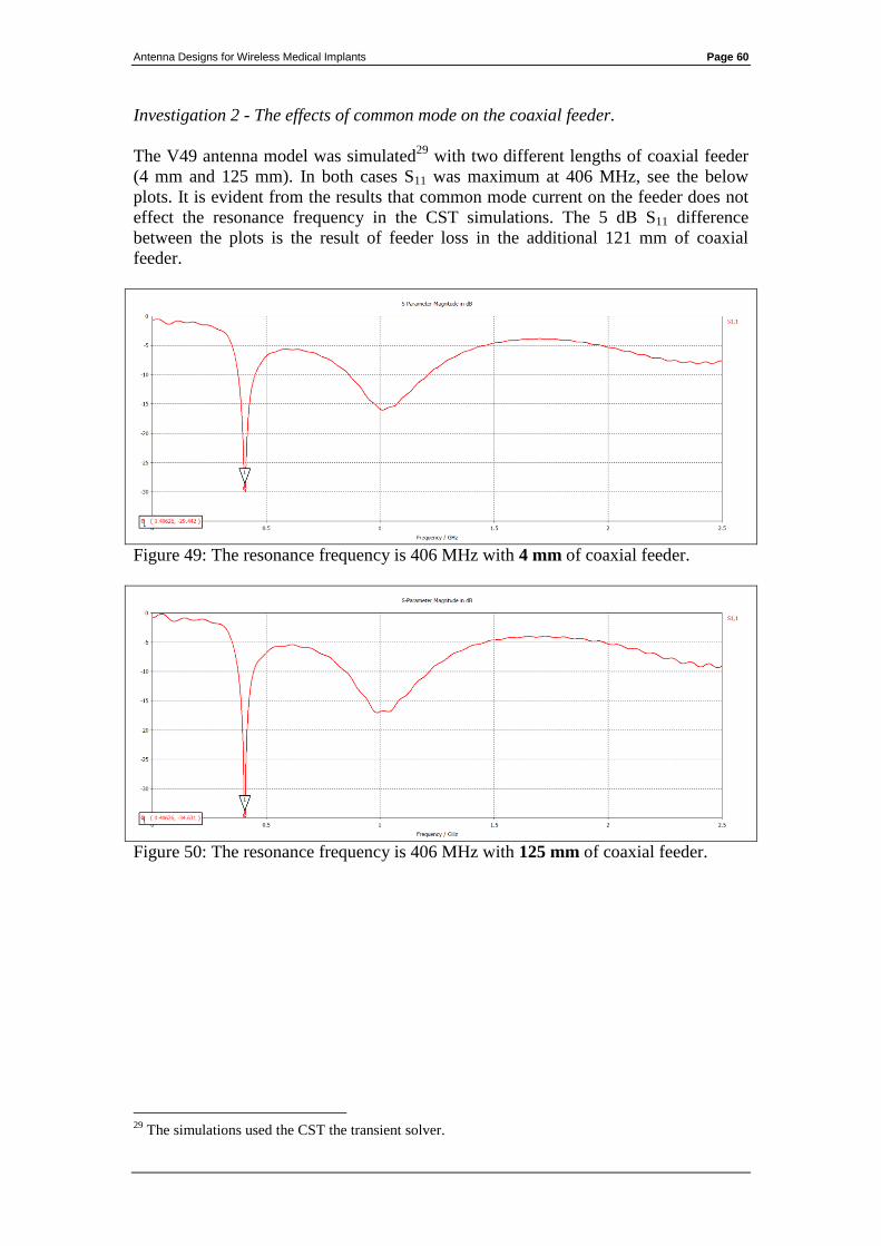
Antenna Designs for Wireless Medical Implants Page 60
Investigation 2 - The effects of common mode on the coaxial feeder.
The V49 antenna model was simulated29
with two different lengths of coaxial feeder
(4 mm and 125 mm). In both cases S11 was maximum at 406 MHz, see the below
plots. It is evident from the results that common mode current on the feeder does not
effect the resonance frequency in the CST simulations. The 5 dB S11 difference
between the plots is the result of feeder loss in the additional 121 mm of coaxial
feeder.
Figure 49: The resonance frequency is 406 MHz with 4 mm of coaxial feeder.
Figure 50: The resonance frequency is 406 MHz with 125 mm of coaxial feeder.
29
The simulations used the CST the transient solver.

Antenna Designs for Wireless Medical Implants Page 61
Investigation 3 - Agreement between free space S11 predictions and measurements.
The frequency discrepancy was observed between the predictions and measurements
when both were in a dielectrically loaded condition. The S11 performance was
simulated and measured in the un-loaded condition (i.e. without a phantom) for
comparison purposes. The prediction and measurement data agreed closely, indicating
that the discrepancy is related to the effects of dielectric loading. The measurements
showed a 2 dB increase in S11 at higher frequencies (circa 2.5 GHz). This is again due
to the lower feeder losses in the CST model.
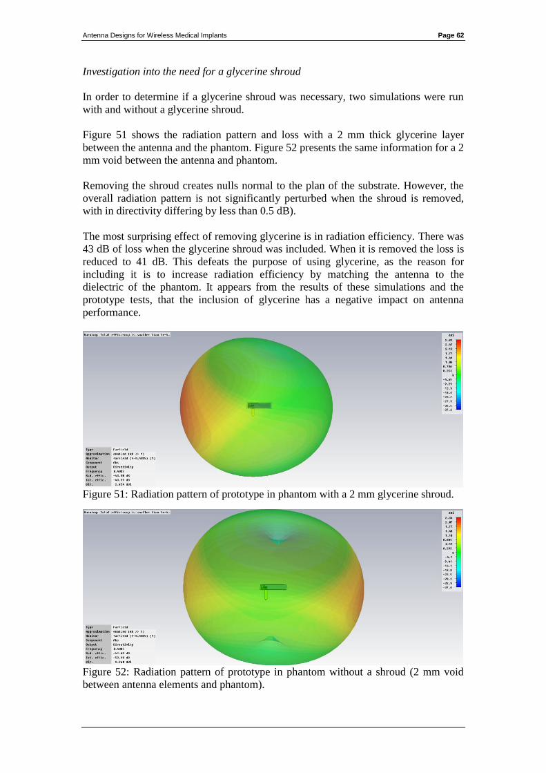
Antenna Designs for Wireless Medical Implants Page 62
Investigation into the need for a glycerine shroud
In order to determine if a glycerine shroud was necessary, two simulations were run
with and without a glycerine shroud.
Figure 51 shows the radiation pattern and loss with a 2 mm thick glycerine layer
between the antenna and the phantom. Figure 52 presents the same information for a 2
mm void between the antenna and phantom.
Removing the shroud creates nulls normal to the plan of the substrate. However, the
overall radiation pattern is not significantly perturbed when the shroud is removed,
with in directivity differing by less than 0.5 dB).
The most surprising effect of removing glycerine is in radiation efficiency. There was
43 dB of loss when the glycerine shroud was included. When it is removed the loss is
reduced to 41 dB. This defeats the purpose of using glycerine, as the reason for
including it is to increase radiation efficiency by matching the antenna to the
dielectric of the phantom. It appears from the results of these simulations and the
prototype tests, that the inclusion of glycerine has a negative impact on antenna
performance.
Figure 51: Radiation pattern of prototype in phantom with a 2 mm glycerine shroud.
Figure 52: Radiation pattern of prototype in phantom without a shroud (2 mm void
between antenna elements and phantom).
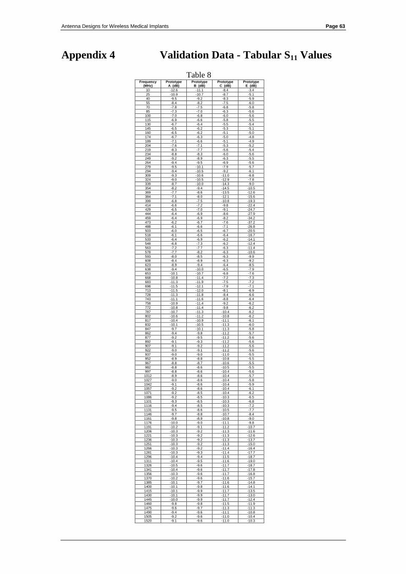
Antenna Designs for Wireless Medical Implants Page 63
Appendix 4 Validation Data - Tabular S11 Values
Table 8 Frequency
(MHz) Prototype
A (dB) Prototype
B (dB) Prototype
C (dB) Prototype
E (dB)
10 -12.6 -11.1 -8.4 -3.4
25 -10.9 -10.7 -8.7 -5.1
40 -9.5 -9.2 -8.3 -5.9
55 -8.4 -8.2 -7.5 -6.0
70 -7.8 -7.5 -6.8 -5.8
85 -7.3 -7.0 -6.3 -5.6
100 -7.0 -6.8 -6.0 -5.6
115 -6.9 -6.6 -5.8 -5.5
130 -6.7 -6.4 -5.5 -5.4
145 -6.5 -6.2 -5.3 -5.1
160 -6.5 -6.2 -5.1 -5.0
174 -6.7 -6.3 -5.0 -4.8
189 -7.1 -6.6 -5.1 -4.9
204 -7.6 -7.1 -5.3 -5.2
219 -8.3 -7.7 -5.6 -5.4
234 -8.8 -8.3 -6.0 -5.6
249 -9.2 -8.9 -6.3 -5.5
264 -9.4 -9.5 -6.9 -5.6
279 -9.5 -10.1 -7.9 -5.7
294 -9.4 -10.5 -9.2 -6.1
309 -9.3 -10.6 -11.0 -6.8
324 -9.0 -10.5 -12.9 -7.8
339 -8.7 -10.0 -14.3 -9.0
354 -8.2 -9.4 -14.5 -10.5
369 -7.7 -8.6 -13.5 -12.6
384 -7.1 -8.0 -12.1 -15.6
399 -6.8 -7.5 -10.8 -19.3
414 -6.6 -7.2 -9.8 -22.4
429 -6.5 -7.0 -9.1 -24.7
444 -6.4 -6.9 -8.6 -27.9
459 -6.4 -6.9 -8.2 -34.2
473 -6.2 -6.7 -7.6 -37.2
488 -6.1 -6.6 -7.1 -26.8
503 -6.0 -6.5 -6.7 -20.5
518 -6.1 -6.6 -6.4 -16.7
533 -6.4 -6.9 -6.2 -14.1
548 -6.8 -7.3 -6.2 -12.4
563 -7.2 -7.7 -6.3 -11.4
578 -7.7 -8.2 -6.3 -10.6
593 -8.0 -8.5 -6.3 -9.9
608 -8.4 -8.9 -6.3 -9.2
623 -8.9 -9.4 -6.4 -8.5
638 -9.4 -10.0 -6.5 -7.9
653 -10.1 -10.7 -6.8 -7.6
668 -10.8 -11.4 -7.2 -7.3
683 -11.3 -11.9 -7.5 -7.2
698 -11.5 -12.1 -7.9 -7.1
713 -11.5 -12.0 -8.1 -6.9
728 -11.3 -11.8 -8.4 -6.6
743 -11.1 -11.6 -8.8 -6.4
758 -10.9 -11.4 -9.2 -6.2
772 -10.8 -11.4 -9.8 -6.2
787 -10.7 -11.3 -10.4 -6.2
802 -10.6 -11.2 -10.8 -6.2
817 -10.4 -10.9 -11.1 -6.1
832 -10.1 -10.5 -11.3 -6.0
847 -9.7 -10.1 -11.3 -5.8
862 -9.4 -9.8 -11.2 -5.7
877 -9.2 -9.5 -11.2 -5.6
892 -9.1 -9.3 -11.2 -5.6
907 -9.1 -9.2 -11.2 -5.6
922 -9.0 -9.1 -11.2 -5.6
937 -9.0 -9.0 -11.0 -5.5
952 -8.9 -8.8 -10.8 -5.5
967 -8.8 -8.7 -10.6 -5.5
982 -8.8 -8.6 -10.5 -5.5
997 -8.8 -8.6 -10.4 -5.6
1012 -8.9 -8.6 -10.4 -5.7
1027 -9.0 -8.6 -10.4 -5.8
1042 -9.1 -8.6 -10.4 -5.9
1057 -9.2 -8.6 -10.4 -6.1
1071 -9.2 -8.5 -10.4 -6.2
1086 -9.2 -8.5 -10.3 -6.5
1101 -9.3 -8.5 -10.3 -6.8
1116 -9.4 -8.5 -10.3 -7.2
1131 -9.5 -8.6 -10.5 -7.7
1146 -9.7 -8.8 -10.7 -8.4
1161 -9.8 -8.9 -10.8 -9.0
1176 -10.0 -9.0 -11.1 -9.8
1191 -10.2 -9.1 -11.2 -10.7
1206 -10.3 -9.2 -11.3 -11.6
1221 -10.3 -9.2 -11.3 -12.6
1236 -10.3 -9.2 -11.3 -13.7
1251 -10.3 -9.2 -11.3 -15.0
1266 -10.3 -9.2 -11.4 -16.4
1281 -10.3 -9.3 -11.4 -17.7
1296 -10.4 -9.4 -11.5 -18.7
1311 -10.4 -9.5 -11.6 -19.0
1326 -10.5 -9.6 -11.7 -18.7
1341 -10.4 -9.6 -11.7 -17.8
1356 -10.3 -9.6 -11.7 -16.8
1370 -10.2 -9.6 -11.6 -15.7
1385 -10.1 -9.7 -11.6 -14.8
1400 -10.1 -9.8 -11.6 -14.1
1415 -10.1 -9.9 -11.7 -13.5
1430 -10.1 -9.9 -11.7 -13.0
1445 -10.0 -9.9 -11.7 -12.4
1460 -9.8 -9.8 -11.5 -11.9
1475 -9.6 -9.7 -11.3 -11.3
1490 -9.4 -9.6 -11.1 -10.8
1505 -9.2 -9.6 -11.0 -10.4
1520 -9.1 -9.6 -11.0 -10.3
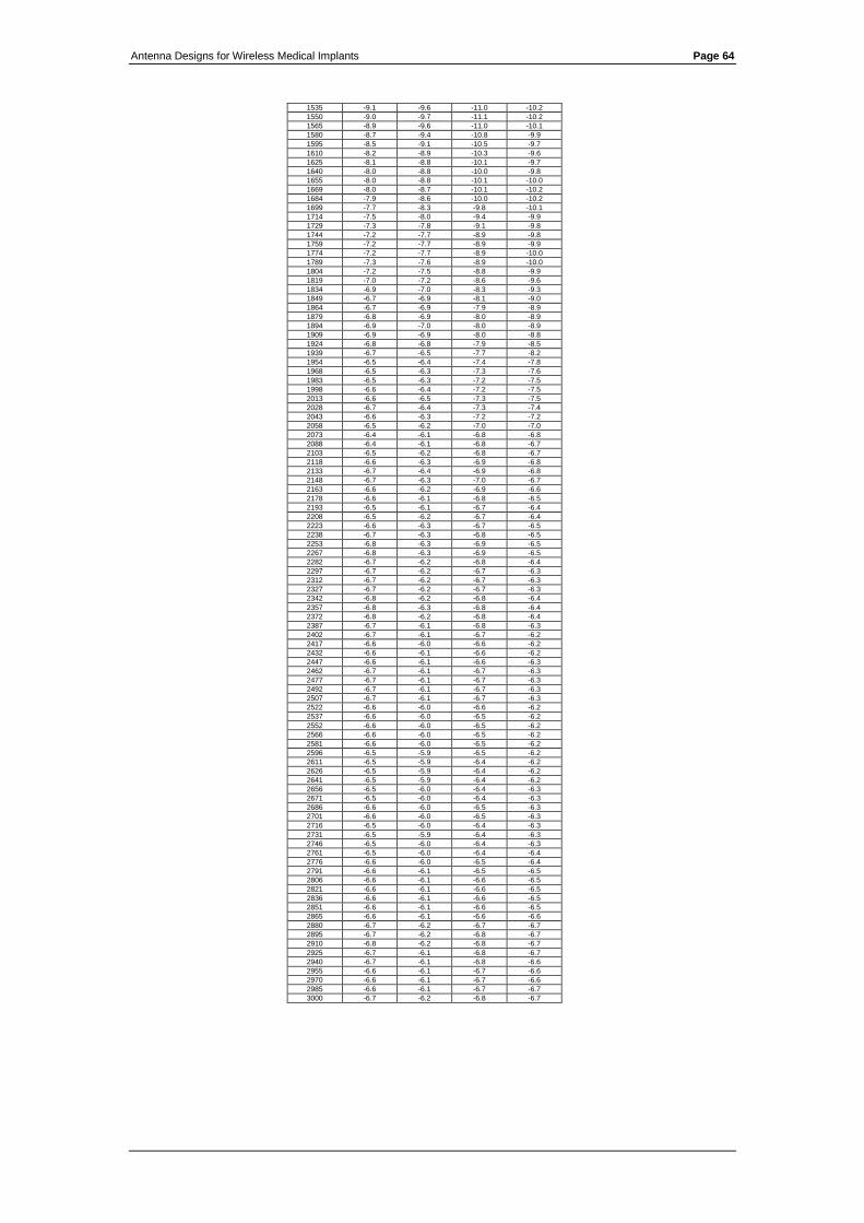
Antenna Designs for Wireless Medical Implants Page 64
1535 -9.1 -9.6 -11.0 -10.2
1550 -9.0 -9.7 -11.1 -10.2
1565 -8.9 -9.6 -11.0 -10.1
1580 -8.7 -9.4 -10.8 -9.9
1595 -8.5 -9.1 -10.5 -9.7
1610 -8.2 -8.9 -10.3 -9.6
1625 -8.1 -8.8 -10.1 -9.7
1640 -8.0 -8.8 -10.0 -9.8
1655 -8.0 -8.8 -10.1 -10.0
1669 -8.0 -8.7 -10.1 -10.2
1684 -7.9 -8.6 -10.0 -10.2
1699 -7.7 -8.3 -9.8 -10.1
1714 -7.5 -8.0 -9.4 -9.9
1729 -7.3 -7.8 -9.1 -9.8
1744 -7.2 -7.7 -8.9 -9.8
1759 -7.2 -7.7 -8.9 -9.9
1774 -7.2 -7.7 -8.9 -10.0
1789 -7.3 -7.6 -8.9 -10.0
1804 -7.2 -7.5 -8.8 -9.9
1819 -7.0 -7.2 -8.6 -9.6
1834 -6.9 -7.0 -8.3 -9.3
1849 -6.7 -6.9 -8.1 -9.0
1864 -6.7 -6.9 -7.9 -8.9
1879 -6.8 -6.9 -8.0 -8.9
1894 -6.9 -7.0 -8.0 -8.9
1909 -6.9 -6.9 -8.0 -8.8
1924 -6.8 -6.8 -7.9 -8.5
1939 -6.7 -6.5 -7.7 -8.2
1954 -6.5 -6.4 -7.4 -7.8
1968 -6.5 -6.3 -7.3 -7.6
1983 -6.5 -6.3 -7.2 -7.5
1998 -6.6 -6.4 -7.2 -7.5
2013 -6.6 -6.5 -7.3 -7.5
2028 -6.7 -6.4 -7.3 -7.4
2043 -6.6 -6.3 -7.2 -7.2
2058 -6.5 -6.2 -7.0 -7.0
2073 -6.4 -6.1 -6.8 -6.8
2088 -6.4 -6.1 -6.8 -6.7
2103 -6.5 -6.2 -6.8 -6.7
2118 -6.6 -6.3 -6.9 -6.8
2133 -6.7 -6.4 -6.9 -6.8
2148 -6.7 -6.3 -7.0 -6.7
2163 -6.6 -6.2 -6.9 -6.6
2178 -6.6 -6.1 -6.8 -6.5
2193 -6.5 -6.1 -6.7 -6.4
2208 -6.5 -6.2 -6.7 -6.4
2223 -6.6 -6.3 -6.7 -6.5
2238 -6.7 -6.3 -6.8 -6.5
2253 -6.8 -6.3 -6.9 -6.5
2267 -6.8 -6.3 -6.9 -6.5
2282 -6.7 -6.2 -6.8 -6.4
2297 -6.7 -6.2 -6.7 -6.3
2312 -6.7 -6.2 -6.7 -6.3
2327 -6.7 -6.2 -6.7 -6.3
2342 -6.8 -6.2 -6.8 -6.4
2357 -6.8 -6.3 -6.8 -6.4
2372 -6.8 -6.2 -6.8 -6.4
2387 -6.7 -6.1 -6.8 -6.3
2402 -6.7 -6.1 -6.7 -6.2
2417 -6.6 -6.0 -6.6 -6.2
2432 -6.6 -6.1 -6.6 -6.2
2447 -6.6 -6.1 -6.6 -6.3
2462 -6.7 -6.1 -6.7 -6.3
2477 -6.7 -6.1 -6.7 -6.3
2492 -6.7 -6.1 -6.7 -6.3
2507 -6.7 -6.1 -6.7 -6.3
2522 -6.6 -6.0 -6.6 -6.2
2537 -6.6 -6.0 -6.5 -6.2
2552 -6.6 -6.0 -6.5 -6.2
2566 -6.6 -6.0 -6.5 -6.2
2581 -6.6 -6.0 -6.5 -6.2
2596 -6.5 -5.9 -6.5 -6.2
2611 -6.5 -5.9 -6.4 -6.2
2626 -6.5 -5.9 -6.4 -6.2
2641 -6.5 -5.9 -6.4 -6.2
2656 -6.5 -6.0 -6.4 -6.3
2671 -6.5 -6.0 -6.4 -6.3
2686 -6.6 -6.0 -6.5 -6.3
2701 -6.6 -6.0 -6.5 -6.3
2716 -6.5 -6.0 -6.4 -6.3
2731 -6.5 -5.9 -6.4 -6.3
2746 -6.5 -6.0 -6.4 -6.3
2761 -6.5 -6.0 -6.4 -6.4
2776 -6.6 -6.0 -6.5 -6.4
2791 -6.6 -6.1 -6.5 -6.5
2806 -6.6 -6.1 -6.6 -6.5
2821 -6.6 -6.1 -6.6 -6.5
2836 -6.6 -6.1 -6.6 -6.5
2851 -6.6 -6.1 -6.6 -6.5
2865 -6.6 -6.1 -6.6 -6.6
2880 -6.7 -6.2 -6.7 -6.7
2895 -6.7 -6.2 -6.8 -6.7
2910 -6.8 -6.2 -6.8 -6.7
2925 -6.7 -6.1 -6.8 -6.7
2940 -6.7 -6.1 -6.8 -6.6
2955 -6.6 -6.1 -6.7 -6.6
2970 -6.6 -6.1 -6.7 -6.6
2985 -6.6 -6.1 -6.7 -6.7
3000 -6.7 -6.2 -6.8 -6.7
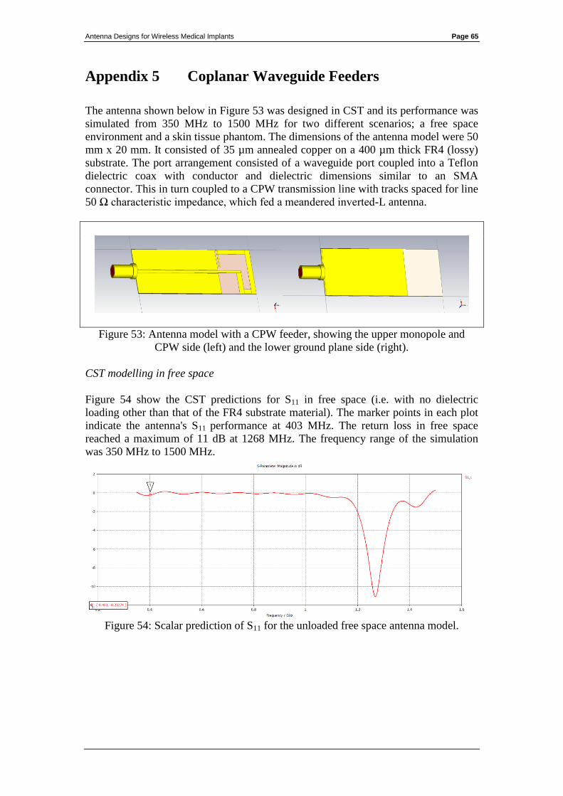
Antenna Designs for Wireless Medical Implants Page 65
Appendix 5 Coplanar Waveguide Feeders
The antenna shown below in Figure 53 was designed in CST and its performance was
simulated from 350 MHz to 1500 MHz for two different scenarios; a free space
environment and a skin tissue phantom. The dimensions of the antenna model were 50
mm x 20 mm. It consisted of 35 µm annealed copper on a 400 µm thick FR4 (lossy)
substrate. The port arrangement consisted of a waveguide port coupled into a Teflon
dielectric coax with conductor and dielectric dimensions similar to an SMA
connector. This in turn coupled to a CPW transmission line with tracks spaced for line
50 Ω characteristic impedance, which fed a meandered inverted-L antenna.
Figure 53: Antenna model with a CPW feeder, showing the upper monopole and
CPW side (left) and the lower ground plane side (right).
CST modelling in free space
Figure 54 show the CST predictions for S11 in free space (i.e. with no dielectric
loading other than that of the FR4 substrate material). The marker points in each plot
indicate the antenna's S11 performance at 403 MHz. The return loss in free space
reached a maximum of 11 dB at 1268 MHz. The frequency range of the simulation
was 350 MHz to 1500 MHz.
Figure 54: Scalar prediction of S11 for the unloaded free space antenna model.
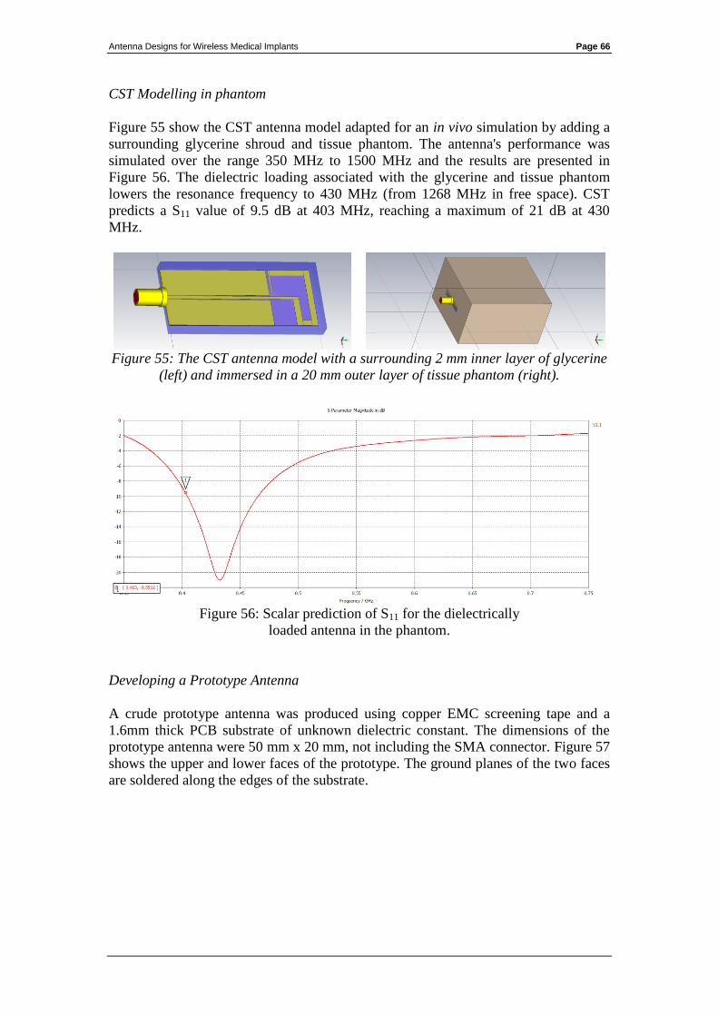
Antenna Designs for Wireless Medical Implants Page 66
CST Modelling in phantom
Figure 55 show the CST antenna model adapted for an in vivo simulation by adding a
surrounding glycerine shroud and tissue phantom. The antenna's performance was
simulated over the range 350 MHz to 1500 MHz and the results are presented in
Figure 56. The dielectric loading associated with the glycerine and tissue phantom
lowers the resonance frequency to 430 MHz (from 1268 MHz in free space). CST
predicts a S11 value of 9.5 dB at 403 MHz, reaching a maximum of 21 dB at 430
MHz.
Figure 55: The CST antenna model with a surrounding 2 mm inner layer of glycerine
(left) and immersed in a 20 mm outer layer of tissue phantom (right).
Figure 56: Scalar prediction of S11 for the dielectrically
loaded antenna in the phantom.
Developing a Prototype Antenna
A crude prototype antenna was produced using copper EMC screening tape and a
1.6mm thick PCB substrate of unknown dielectric constant. The dimensions of the
prototype antenna were 50 mm x 20 mm, not including the SMA connector. Figure 57
shows the upper and lower faces of the prototype. The ground planes of the two faces
are soldered along the edges of the substrate.
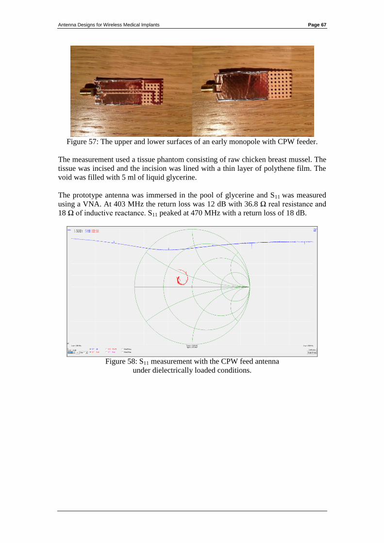
Antenna Designs for Wireless Medical Implants Page 67
Figure 57: The upper and lower surfaces of an early monopole with CPW feeder.
The measurement used a tissue phantom consisting of raw chicken breast mussel. The
tissue was incised and the incision was lined with a thin layer of polythene film. The
void was filled with 5 ml of liquid glycerine.
The prototype antenna was immersed in the pool of glycerine and S11 was measured
using a VNA. At 403 MHz the return loss was 12 dB with 36.8 Ω real resistance and
18 Ω of inductive reactance. S11 peaked at 470 MHz with a return loss of 18 dB.
Figure 58: S11 measurement with the CPW feed antenna
under dielectrically loaded conditions.