antenna ultra wideband enhancement by … · * corresponding author: mohamed hayouni...
TRANSCRIPT

Progress In Electromagnetics Research Letters, Vol. 31, 121–129, 2012
ANTENNA ULTRA WIDEBAND ENHANCEMENT BYNON-UNIFORM MATCHING
M. Hayouni1, *, A. El Oualkadi2, F. Choubani1, T. H. Vuong3,and J. David3
1Innov’COM, Sup’COM, University of Carthage, Tunisia2LabTIC, ENSA de Tanger, Tanger BP 1818, Morocco3ENSEEIHT, France
Abstract—In this paper, antenna ultra wideband enhancement bynon-uniform matching is proposed. The antenna consisted of arectangular shaped radiator with two convex circled corners. Simulatedresults using CST Microwave Studio and measured results of afabricated antenna concord well to prove that it can operate fromabout 3.5 GHz to 4.6GHz and from 7.4 GHz to 12.7 GHz for S11(dB) <−10 dB. In addition, a good impedance matching is noted in the IEEEradar engineering X band range since the return loss coefficient remainsbelow −50 dB value at 9.5GHz and can reach −45 dB at 11 GHz.A current density comparison at 11GHz, supporting our argument,between a stepper corner and convex corner demonstrates that thecurrent density can reach 52A/m with a convex corner whereas it doesnot exceed 33 A/m for the antenna with a stepper corners. Radiationpatterns at various frequencies and peak gains show clearly interestingfeatures of such antennas.
1. INTRODUCTION
Miniaturization and bandwidth enhancement are becoming designconsiderations for practical applications of microstrip antennas.Eventually, researches to reach compact and broadband operationsof microstrip antennas become increasingly expanded. Somedevelopments in allied branches are now being investigated in antennasapplications. Various recent basic principles of broadband designare deployed in the literature. Indeed, the investigation into the
Received 10 March 2012, Accepted 12 April 2012, Scheduled 18 April 2012* Corresponding author: Mohamed Hayouni ([email protected]).
122 Hayouni et al.
performance of proximity coupled stacked patches by the exploration ofthe relationship required between the dielectric layers, the dimensionsof the stacked radiators and the relative location of the feed canachieve a broadband behaviour in excess of 20% as studied in [1].The optimization of the impedance matching through narrow cavitybacked configuration, as described in [2], can enhance the bandwidthof the proposed antenna to more than 40% (VSWR < 2) since it canprovide a larger effective coupling than the conventional proximity-coupled antenna without a narrow cavity backed configuration. Alow Q factor of the magnetic wall under the patch created by alow dielectric constant or larger thickness of the substrate is also anavailable broadband technique [3]. The impedance matching of the feedby probe compensation, using L-shape probe and any reactive loadingas evoked in [4], is another basic principle of broadband design. Inaddition to integration slots in the ground plane of microstrip planarantennas as deployed in [5, 6], or using a rigged ground plane [7] orslots in the radiator as published in [8–12], compact operation withenhanced impedance bandwidth can be obtained. Indeed in [8], theauthors have proposed a UWB antenna; it consisted of a rectangularpatch with two steps, a single slot on the patch, and a partial groundplane. The proposed antenna was designed to operate from 3.2 to12GHz which the measured and simulated return loss coefficients donot go beyond −27 dB. In addition, in [8], the authors have proposedto replace the rectangular slot inserted into the compact UWB planarantenna proposed in [8] by a U slot in order to reject the WIFI bandfrequency around 5.6GHz, and the return loss coefficient does not gobelow −25 dB through the impedance bandwidth of the radiator. Inthis paper, we propose an ultra wide band antenna enhancement bynon-uniform matching. Indeed, rectangular shaped planar antennaswith concave and convex circled corners are investigated in order toexcite different electric lengths with smooth variations. The later areadjusted to lessen the VSWR between the main resonance frequenciesof the rectangular partial grounded patch antenna. A current densitycomparison at certain frequencies with the prototype proposed in [8]with stepper corners will be studied in order to interpret the highimpedance matching between the microstrip feed line and the load inorder to prove the efficiency of non-uniform patch profiles.
2. ANTENNA DESIGN
The proposed antennas with the two configurations B and C aresketched in Figure 1. The two designs are a transfer from theconfiguration A published in [8] with steppers corners to non-
Progress In Electromagnetics Research Letters, Vol. 31, 2012 123
(a) (b)
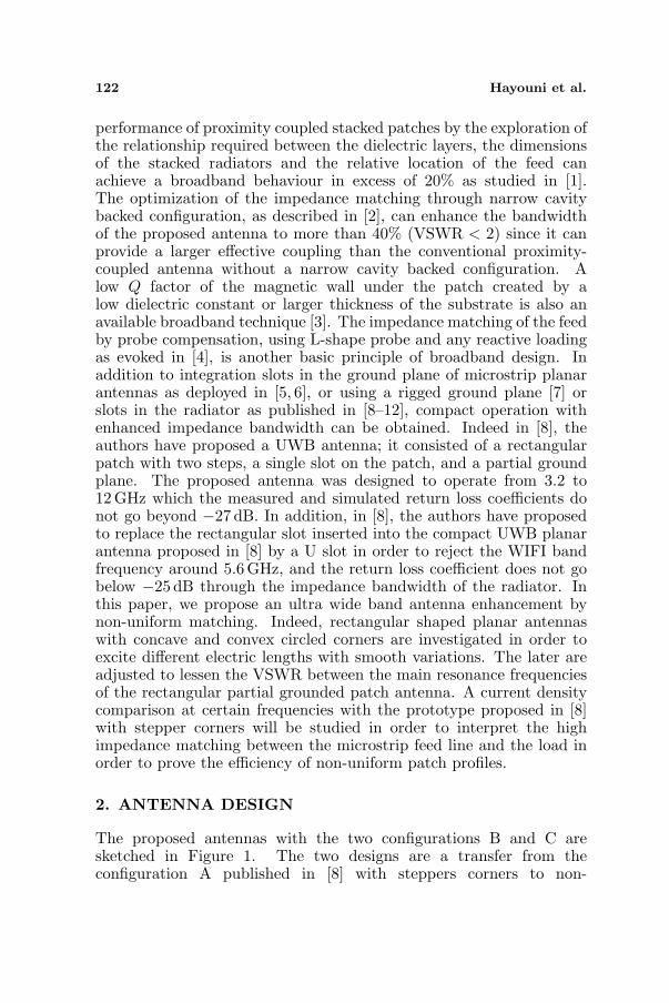
Figure 1. Geometries of the proposed antennas: (a) top view of theconfiguration B and (b) top view of the configuration C.
uniform geometrical corners. The configurations B and C consisted,respectively, of a rectangular shaped perfect electric conductorprinted on a partial grounded FR4 epoxy dielectric substrate of 4.4permittivity, 1.6 mm thick, Lsub = 35mm length and Wsub = 30mmwidth dimensions. The radii of the concave and convex corners arerespectively R and r. The proposed radiators are compact since theyare defined by Lx = 14.5mm and Ly = 15 mm dimensions. The feedingtechnique consisted of a 50 Ω microstrip feed line with a length ofLg = 11.5mm. Various simulations were performed in order to viewthe radius effect on the impedance matching of each antenna in orderto select the suitable form and its radius.
2.1. Configuration B
Various electromagnetic simulations of the prototype B were performedfor different radii R to view its impact on the impedance matching.

124 Hayouni et al.
Figure 2. Return loss of therectangular shaped planar antennawith two concave circled cornersfor various radii.
Figure 3. Return loss coefficientof the rectangular shaped planarantenna with two convex circledcorners for various radii.
Indeed, as depicted by Figure 2, the return loss can reach −33 dBat 12.8 GHz for R = 5.4mm. This return loss coefficient pick mayslightly increase if R decreases. The configuration B is better thanthe configuration A in terms of impedance matching especially in theIEEE radar X band.
2.2. Configuration C
Various electromagnetic simulations of the configuration C (Fig-ure 1(b)) versus r were also performed in order to study the behaviourof the return loss coefficient versus the convex circled curve radius r.Indeed, as depicted by Figure 3, we note a good impedance matchingin the IEEE radar engineering X band range since the return loss canreach −50 dB at 11.25GHz for r = 5.4mm and is less than −50 dBat 9.5 GHz for r = 3 mm. The best simulated prototype which cor-responds to the best impedance matching corresponds to r = 3 mmradius.
Compared to the configuration B, the Configuration C providesa better impedance matching in the IEEE radar X band. In the restof this paper, we propose to present a return loss comparison betweenmeasured and simulated results of a fabricated antenna based on theconfiguration C with r = 3mm radius. Radiation patterns at somefrequencies and peak gain will also be presented.
Progress In Electromagnetics Research Letters, Vol. 31, 2012 125
(a) (b)
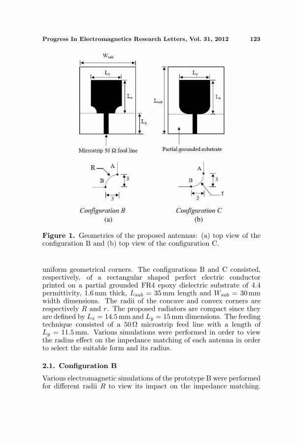
Figure 4. Simulated current distributions at 11 GHz on therectangular patch antenna with: (a) two convex circled forms ofr = 3 mm and (b) stepper corners.
2.3. Current Density
The current distribution normally gives an insight into the physicalbehaviour of the antenna. In simulation, antennas with stepper andconvex circled corners are investigated at various frequencies. Indeed,Figure 4 shows the current distribution at 11 GHz frequency supportingour argument of the convex circled corners geometry contribution inthe impedance matching in IEEE radar engineering X band rangecompared to stepped two corners contribution. Higher current densitycan be observed at the two convex circled corners of the UWB radiatorthat reaches 52A/m. This current density value is higher than thecurrent density at the stepper corners radiator presented in [8] thatdoes not exceed 32.5 A/m at the same frequency. It is obvious that theinput power is much more efficiently sent to the radiator when usingtwo convex corners. This supports the importance of non-uniformgeometry such as convex circled geometry between the feed line andthe antenna as a good impedance matching tool.
3. RESULTS AND DISCUSSION
3.1. S Parameters
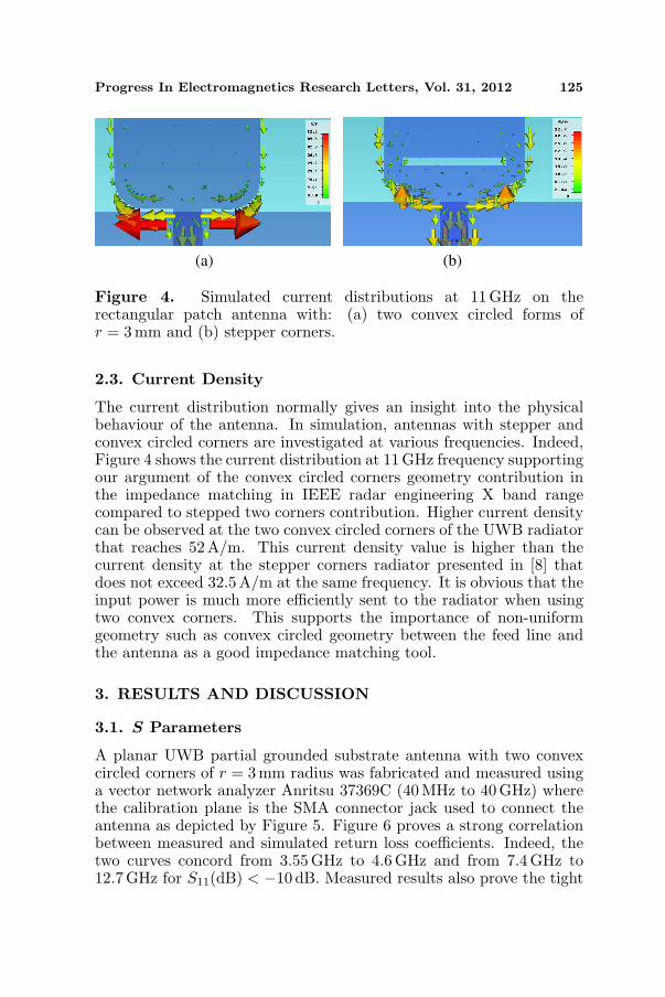
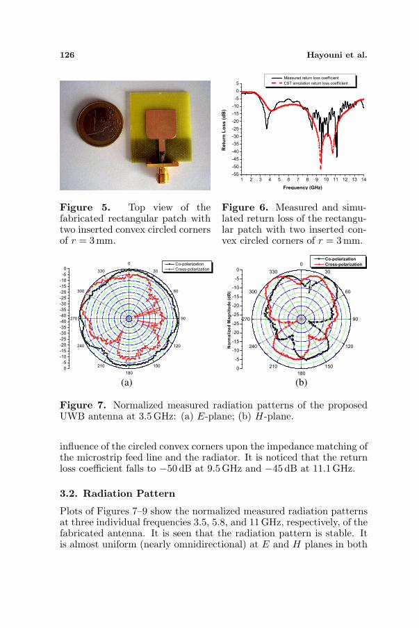
A planar UWB partial grounded substrate antenna with two convexcircled corners of r = 3 mm radius was fabricated and measured usinga vector network analyzer Anritsu 37369C (40MHz to 40 GHz) wherethe calibration plane is the SMA connector jack used to connect theantenna as depicted by Figure 5. Figure 6 proves a strong correlationbetween measured and simulated return loss coefficients. Indeed, thetwo curves concord from 3.55 GHz to 4.6 GHz and from 7.4GHz to12.7GHz for S11(dB) < −10 dB. Measured results also prove the tight
126 Hayouni et al.
Figure 5. Top view of thefabricated rectangular patch withtwo inserted convex circled cornersof r = 3 mm.
Figure 6. Measured and simu-lated return loss of the rectangu-lar patch with two inserted con-vex circled corners of r = 3 mm.
(a) (b)
Figure 7. Normalized measured radiation patterns of the proposedUWB antenna at 3.5 GHz: (a) E-plane; (b) H-plane.
influence of the circled convex corners upon the impedance matching ofthe microstrip feed line and the radiator. It is noticed that the returnloss coefficient falls to −50 dB at 9.5 GHz and −45 dB at 11.1 GHz.
3.2. Radiation Pattern
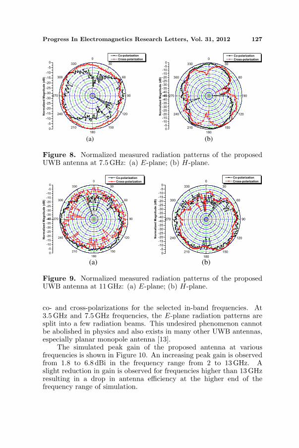
Plots of Figures 7–9 show the normalized measured radiation patternsat three individual frequencies 3.5, 5.8, and 11 GHz, respectively, of thefabricated antenna. It is seen that the radiation pattern is stable. Itis almost uniform (nearly omnidirectional) at E and H planes in both
Progress In Electromagnetics Research Letters, Vol. 31, 2012 127
(a) (b)
Figure 8. Normalized measured radiation patterns of the proposedUWB antenna at 7.5 GHz: (a) E-plane; (b) H-plane.
(a) (b)
Figure 9. Normalized measured radiation patterns of the proposedUWB antenna at 11 GHz: (a) E-plane; (b) H-plane.
co- and cross-polarizations for the selected in-band frequencies. At3.5GHz and 7.5 GHz frequencies, the E-plane radiation patterns aresplit into a few radiation beams. This undesired phenomenon cannotbe abolished in physics and also exists in many other UWB antennas,especially planar monopole antenna [13].
The simulated peak gain of the proposed antenna at variousfrequencies is shown in Figure 10. An increasing peak gain is observedfrom 1.8 to 6.8 dBi in the frequency range from 2 to 13 GHz. Aslight reduction in gain is observed for frequencies higher than 13GHzresulting in a drop in antenna efficiency at the higher end of thefrequency range of simulation.

128 Hayouni et al.
Figure 10. Simulated peak gain of the proposed antenna.
4. CONCLUSION
A rectangular shaped compact UWB antenna with two convex circledcorners has been presented in this paper. The simulated resultsperformed show reasonable agreement with the measured ones. Thefrequency range obtained for S11(dB) < −10 dB extends from 3.55GHzt o 4.6GHz and from 7.4 GHz to 12.7 GHz. Measured results also provethe good effect of the circled convex corners on the impedance matchingof the microstrip feed line and the radiator. A wideband matching isachieved with extremely low return loss, as low as −50 dB at 9.5 GHzand −45 dB at 11.1 GHz.
REFERENCES
1. Waynes, S., T. Rowe, and R. B. Waterhouse, “Investigation intothe performance of proximity coupled stacked patches,” IEEETransaction on Antennas and Propagation, 1693–1698, Jun. 2006.
2. Sun, D. and L. You, “A broadband impedance matching methodfor proximity coupled microstrip antenna,” IEEE Transaction onAntennas and Propagation, 1392–1397, Apr. 2010.
3. Kelly, J. R., P. S. Hall, and P. Gardner, “Planar band-notched UWB antenna,” 3rd Conference Eucap’2009, 1636–1639,Mar. 2009.
4. Wong, K. L., Compact and Broadband Microstrip Antennas,Wiley, NY, 2002.
5. Sim, C.-Y.-D., W.-T. Chung, and C.-H. Lee, “Compactslot antenna for UWB applications,” Antenna and WirelessPropagation Letters, 62–66, 2010.
Progress In Electromagnetics Research Letters, Vol. 31, 2012 129
6. Dastranj, A. and H. Abiri, “Bandwidth enhancement of printedE-shaped slot antennas fed by CPW and microstrip line,” IEEETransaction on Antennas and Propagation, 1402–1407, Apr. 2010.
7. Lin, C.-C. and H.-R. Chuang, “A 3–12 GHz UWB planartriangular monopole antenna with ridged ground-plane,” ProgressIn Electromagnetics Research, Vol. 83, 307–321, 2008.
8. Choi, S. H., J. K. Park, S. K. Kim, and J. Y. Park, “A new ultra-wide band antenna for UWB application,” Microwave and OpticalTechnologies Letters, 399–401, Mar. 2004.
9. Duroc, Y., T.-P. Vuong, and S. Tedjini, “A time/frequency modelof ultrawideband antennas,” IEEE Transaction on Antennas andPropagation, 2342–2350, Aug. 2007.
10. Chen, D. and C. H. Cheng, “A novel compact ultra-wideband (UWB) wide slot antenna with holes,” Progress InElectromagnetics Research, Vol. 94, 343–349, 2009.
11. Fallahi, R., A. A. Kalteh, and M. G. Roozbahani, “A novelUWB elliptical slot antenna with band-notched characteristics,”Progress In Electromagnetics Research, Vol. 82, 127–136, 2008.
12. Zhang, G.-M., J.-S. Hong, and B.-Z. Wang, “Two novel band-notched UWB slot antennas fed by microstrip line,” Progress InElectromagnetics Research, Vol. 78, 209–218, 2008.
13. Sze, J. Y. and K. L. Wong, “Bandwidth enhancement of amicrostripline-fed printed wide-slot antenna,” IEEE Transactionon Antennas and Propagation, 1020–1024, Jul. 2011.