anwendungshinweis nockenwellen anpassung, vag 1.8l, 2 · pdf fileaudi a3 with 4 cylinder...
TRANSCRIPT
Anweisungen der Fahrzeughersteller sind in jedem Fall zu beachten.Please observe the service instructions of the car manufacturer.
ViGOR GmbH • ; Am Langen Siepen 13-15 • 42857 Remscheid • GERMANY[ +49 (0) 21 91 / 97 95 • \ +49 (0) 21 91 / 97 96 00 • ] [email protected] • ^ vigor-equipment.com
V442
4 A
H
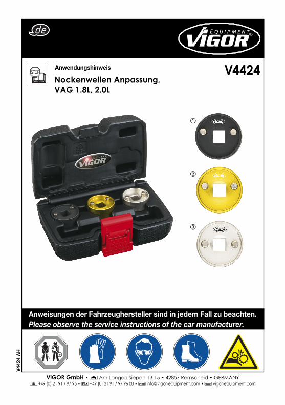
Anwendungshinweis
Nockenwellen Anpassung, VAG 1.8L, 2.0L
V4424
�
�
�
ViGOR GmbH • ; Am Langen Siepen 13-15 • 42857 Remscheid • GERMANY[ +49 (0) 21 91 / 97 95 • \ +49 (0) 21 91 / 97 96 00 • ] [email protected] • ^ vigor-equipment.com
2
Artikel Beschreibung OEM
1Werkzeug zur Entfernung des Nockenwellen-Steuerventils
T10352/1
2Werkzeug zur Entfernung des Nockenwellen-Steuerventils
T10352
3Werkzeug zur Entfernung des Nockenwellen-Steuerventils
T10352/2
Anwendung
Satz bestehend aus 3 Montage-Hilfsmitteln für die Nockenwelle. Für den Ein- und Ausbau des 4-/3-Wege Zentralventils für die Nockenwellen-Einstellung. Dieser Satz enthält das Originalwerkzeug T10352 und die neuen Werkzeugversionen T10352/1 und T10352/2. Satz von 3 Steckschlüssel-Einsätzen. 3/8“ Einsatz, Außendurchmesser 34 mm.
Modell:4-Zylinder-Einspritzmotor (1,8 Liter und 2,0 Liter Motor, Kettenantrieb)
AUDI: A3 (2004)VOLKSWAGEN: Passat (2006), Passat CC (2009)AUDI: A3 mit direkteinspritzendem 4-Zylinder-Motor, 1,8/2,0 Liter 4v TSFi-Motor mit KetteAUDI: A4 (2008), A5 Cabriolet (2009), A5 Coupe (2008), Q5 (2008), A3 (2012)

ViGOR GmbH • ; Am Langen Siepen 13-15 • 42857 Remscheid • GERMANY[ +49 (0) 21 91 / 97 95 • \ +49 (0) 21 91 / 97 96 00 • ] [email protected] • ^ vigor-equipment.com
3
Hersteller Modell Typ Motorcode Jahr
AUDI
A3 1.8 | 2.0 TFSi/TSI
BYT | BZB
2007-2013
CABA | CABB
CABD | CAWB
CBFA | CCTA
CCZA | CCZB
CCZC | CDHA
CDHB | CDNB
CDNC | CDND
A4 1.8 | 2.0 TFSi/TSI CFKA | CGYA 2007-2013
A5 1.8 | 2.0 TFSi/TSI CCZA | CCZB 2007-2013
Q5 1.8 | 2.0 TFSi/TSI CCZC | CCZD 2007-2013
TT 1.8 | 2.0 TFSi/TSI CDAA | CDAB 2008-2013
SEAT Altea 1.8 | 2.0 TFSi/TSI BYT | BZB 2009-2013
Leon 1.8 | 2.0 TFSi/TSI CABA | CABB 2007-2013
Toledo 1.8 | 2.0 TFSi/TSI CABD | CAWB 2007-2013
Exeo 1.8 | 2.0 TFSi/TSI CBFA | CCTA 2010-2013
SKODA
Octavia II 1.8 | 2.0 TFSi/TSI CCZA | CCZB 2007-2013
Superb II 1.8 | 2.0 TFSi/TSI CCZC | CDHA 2008-2013
Yeti 1.8 | 2.0 TFSi/TSI CDHB | CDNB 2009-2013
VOLKSWAGEN
Eos 1.8 | 2.0 TFSi/TSI CDNC | CDND 2008-2013
Golf 1.8 | 2.0 TFSi/TSI CFKA | CGYA 2007-2013
Jetta 1.8 | 2.0 TFSi/TSI CCZA | CCZB 2007-2011
Passat 1.8 | 2.0 TFSi/TSI CCZC | CCZD 2007-2013
Scirocco 1.8 | 2.0 TFSi/TSI CDAA | CDAB 2008-2013
Sharan 1.8 | 2.0 TFSi/TSI 2011-2013
Tiguan 1.8 | 2.0 TFSi/TSI 2007-2013

ViGOR GmbH • ; Am Langen Siepen 13-15 • 42857 Remscheid • GERMANY[ +49 (0) 21 91 / 97 95 • \ +49 (0) 21 91 / 97 96 00 • ] [email protected] • ^ vigor-equipment.com
4
1. In Servicestellung bringen
2. Motorabdeckplatte entfernen -Siehe Pfeile. Luftführung zusammen mit dem Luftschlauch am Unterteil ablösen.
Anwendung
Vor-Inbetriebnahme:- Motorabdeckung entfernen.- Entfernen Sie die elektrischen Verbindungen vom Elektromagnet des Hubwellen-Steuerventils.- Oberen Steuergehäusedeckel entfernen.
Werkzeug zur Entfernung des Nockenwellen-Steuerventils (T10352 & T10352/1)Das Steuerventil mit einem geeigneten Schraubenschlüssel, mit der passenden Werkzeugseite, wie angegeben im Uhrzeigersinn abschrauben.
Werkzeug zur Entfernung des Nockenwellen-Steuerventils (T10352/2)
DemontageHINWEIS: Dichtfl ächen am Boden des Zylinderkopfes, Zylinderkopfabdeckung und - oberseite dürfen nicht maschinell bearbeitet werden. Die Nockenwellenlager sind in den Zylinderkopf und die Zylinderkopfabdeckung integriert. Die Steuerkette muss vor dem Ausbau der Zylinderkopfabdeckung gelockert werden. Beim Einbau Kabelbinder an den Originalpositionen anbringen.
1/2

ViGOR GmbH • ; Am Langen Siepen 13-15 • 42857 Remscheid • GERMANY[ +49 (0) 21 91 / 97 95 • \ +49 (0) 21 91 / 97 96 00 • ] [email protected] • ^ vigor-equipment.com
5
3. Schlauch 1 vom Luftfi lter abtrennen. Luftansaug- schlauch 2 abtrennen. Luftfi ltergehäuse nach oben ziehen -Siehe Pfeile. Die Öffnungen mit Verschlussstopfen aus dem Motorstopfen-Satz VAS 6122 verschließen.
4. Ziehen Sie für die für die Einstellung der Nockenwelle die elektrischen Anschlüsse -Siehe Pfeile- an den Stellgeräten ab.
5. Lösen Sie den elektrischen Anschluss für die Lambdasonde -1- vom Gegenhalter. Lösen Sie die elektrischen Anschlüsse an den Zündspulen und ziehen Sie sie zeitgleich von den Zündspulen ab. Entfernen Sie die Bolzen der Zündspulen und ziehen Sie die Zündspulen heraus.
6. Entfernen Sie die Stellgeräte für die Nockenwellen-Einstellung -Siehe Pfeile.

ViGOR GmbH • ; Am Langen Siepen 13-15 • 42857 Remscheid • GERMANY[ +49 (0) 21 91 / 97 95 • \ +49 (0) 21 91 / 97 96 00 • ] [email protected] • ^ vigor-equipment.com
6
11. Drehen Sie (3) in Pfeilrichtung um das Steuerventil zu entfernen (linke und rechte Seite).
7. Lösen Sie den Schlauch der Kurbelgehäuseentlüf- tung -1. Entfernen Sie die Bolzen -Siehe Pfeile. Lösen Sie das Kurbelgehäuseentlüftungs-System ab und trennen Sie es in Richtung des Pfeils vom Schlauch der Kurbelgehäuseentlüftung -2.
8. Rohr lösen -Siehe Pfeile. Ziehen Sie den elektrischen Anschluss -1-vom Hallgeber G40 ab.
9. Ziehen Sie den Anschluss -1- vom Auslassnocken- wellen-Steuerventil 1 -N318- und Anschluss -2- vom Auslassnockenwellen-Steuerventil 1 -N205- ab. Lösen Sie die Bolzen -Siehe Pfeile- und entfernen Sie das Nockenwellen-Steuerventil 1 -N205- und Auslass nockenwellen-Steuerventil 1 -N318-.
10. Lösen Sie die Bolzen -1 bis 6- und entfernen Sie die Steuerketten-Abdeckung (Oberteil).
Vorsicht: Die Steuerventile haben ein Linksgewinde.
3

ViGOR GmbH • ; Am Langen Siepen 13-15 • 42857 Remscheid • GERMANY[ +49 (0) 21 91 / 97 95 • \ +49 (0) 21 91 / 97 96 00 • ] [email protected] • ^ vigor-equipment.com
7
Notizen / Notes

ViGOR GmbH • ; Am Langen Siepen 13-15 • 42857 Remscheid • GERMANY[ +49 (0) 21 91 / 97 95 • \ +49 (0) 21 91 / 97 96 00 • ] [email protected] • ^ vigor-equipment.com
8
ViGOR GmbH • ; Am Langen Siepen 13-15 • 42857 Remscheid • GERMANY[ +49 (0) 21 91 / 97 95 • \ +49 (0) 21 91 / 97 96 00 • ] [email protected] • ^ vigor-equipment.com
Notizen / Notes

ViGOR GmbH • ; Am Langen Siepen 13-15 • 42857 Remscheid • GERMANY[ +49 (0) 21 91 / 97 95 • \ +49 (0) 21 91 / 97 96 00 • ] [email protected] • ^ vigor-equipment.com
9
Application note
Adjustment of camshafts VAG 1.8L, 2.0L
V4424
�
�
�
Anweisungen der Fahrzeughersteller sind in jedem Fall zu beachten.Please observe the service instructions of the car manufacturer.

ViGOR GmbH • ; Am Langen Siepen 13-15 • 42857 Remscheid • GERMANY[ +49 (0) 21 91 / 97 95 • \ +49 (0) 21 91 / 97 96 00 • ] [email protected] • ^ vigor-equipment.com
10
Item Description OEM
1Camshaft Control Valve Removal Tool
T10352/1
2Camshaft Control Valve Removal Tool
T10352
3Camshaft Control Valve Removal Tool
T10352/2
Application
Set of 3 Assembly Camshaft Tools. For installation and removal of the 4/3-way central valve for camshaft adjustment. This set includes the original tool T10352 and the new tool versions T10352/1 and T10352/2. Set of 3 sockets. 3/8“ socket, outside diameter 34 mm.
Model:4 cylinder injection engine (1.8 litre and 2.0 litre engine, chain drive)
AUDI: A3 (2004)VOLKSWAGEN: Passat (2006), Passat CC (2009)AUDI A3 with 4 cylinder direct injection, 1.8/2.0 liter 4v TSFI engine with chainAUDI: A4 (2008), A5 Cabriolet (2009), A5 Coupe (2008), Q5 (2008), A3 (2012)

ViGOR GmbH • ; Am Langen Siepen 13-15 • 42857 Remscheid • GERMANY[ +49 (0) 21 91 / 97 95 • \ +49 (0) 21 91 / 97 96 00 • ] [email protected] • ^ vigor-equipment.com
11
Manufacturer Model Vehicle Type Engine Code Year
AUDI
A3 1.8 | 2.0 TFSi/TSI
BYT | BZB
2007-2013
CABA | CABB
CABD | CAWB
CBFA | CCTA
CCZA | CCZB
CCZC | CDHA
CDHB | CDNB
CDNC | CDND
A4 1.8 | 2.0 TFSi/TSI CFKA | CGYA 2007-2013
A5 1.8 | 2.0 TFSi/TSI CCZA | CCZB 2007-2013
Q5 1.8 | 2.0 TFSi/TSI CCZC | CCZD 2007-2013
TT 1.8 | 2.0 TFSi/TSI CDAA | CDAB 2008-2013
SEAT Altea 1.8 | 2.0 TFSi/TSI BYT | BZB 2009-2013
Leon 1.8 | 2.0 TFSi/TSI CABA | CABB 2007-2013
Toledo 1.8 | 2.0 TFSi/TSI CABD | CAWB 2007-2013
Exeo 1.8 | 2.0 TFSi/TSI CBFA | CCTA 2010-2013
SKODA
Octavia II 1.8 | 2.0 TFSi/TSI CCZA | CCZB 2007-2013
Superb II 1.8 | 2.0 TFSi/TSI CCZC | CDHA 2008-2013
Yeti 1.8 | 2.0 TFSi/TSI CDHB | CDNB 2009-2013
VOLKSWAGEN
Eos 1.8 | 2.0 TFSi/TSI CDNC | CDND 2008-2013
Golf 1.8 | 2.0 TFSi/TSI CFKA | CGYA 2007-2013
Jetta 1.8 | 2.0 TFSi/TSI CCZA | CCZB 2007-2011
Passat 1.8 | 2.0 TFSi/TSI CCZC | CCZD 2007-2013
Scirocco 1.8 | 2.0 TFSi/TSI CDAA | CDAB 2008-2013
Sharan 1.8 | 2.0 TFSi/TSI 2011-2013
Tiguan 1.8 | 2.0 TFSi/TSI 2007-2013

ViGOR GmbH • ; Am Langen Siepen 13-15 • 42857 Remscheid • GERMANY[ +49 (0) 21 91 / 97 95 • \ +49 (0) 21 91 / 97 96 00 • ] [email protected] • ^ vigor-equipment.com
12
1. Place into service position
2. Remove engine cover panel -see arrows. Detach air guide at the bottom together with the air hose.
Application
Before starting the operation:Remove engine top cover.- Remove the electrical connections from the cam control valve solenoid.- Remove upper timing cover.
Camshaft Control Valve Removal Tool (T10352 & T10352/1)Using a suitable wrench, unscrew the control valve in a clockwise direction as indicated using the appropriate face of the tool.
Camshaft Control Valve Removal Tool (T10352/2)
RemovalNOTE: Sealing surfaces at the bottom of the cylinder head, cover and top of cylinder head must not be machined. The camshaft bearings are integrated into the cylinder head and cylinder head cover. The timing chain must be slackened before removing the cylinder head cover. Fit cable ties in the original positions when installing.
1/2

ViGOR GmbH • ; Am Langen Siepen 13-15 • 42857 Remscheid • GERMANY[ +49 (0) 21 91 / 97 95 • \ +49 (0) 21 91 / 97 96 00 • ] [email protected] • ^ vigor-equipment.com
13
3. Disconnect hose 1 from the air cleaner. Disconnect air intake hose 2. Pull the air cleaner housing upwards -see arrows. Plug openings in with sealing plugs from the engine bung set -VAS 6122.
4. Unplug electrical connectors -see arrows- at actuators for camshaft adjustment.
5. Detach the electrical connector for the Lambda probe -1- from the retainer. Release electrical connectors at ignition coils and unplug from ignition coils simultaneously. Remove bolts for ignition coils and pull out ignition coils.
6. Remove actuators for camshaft adjustment - see arrows.

ViGOR GmbH • ; Am Langen Siepen 13-15 • 42857 Remscheid • GERMANY[ +49 (0) 21 91 / 97 95 • \ +49 (0) 21 91 / 97 96 00 • ] [email protected] • ^ vigor-equipment.com
14
11. Turn (3) in direction of -arrow- to remove timing valve (left and right sides).
7. Detach the crankcase breather hose -1. Remove the bolts -see arrows. Detach the crankcase breather system and disconnect from crankcase breather hose -2 in direction of -arrow-.
8. Disconnect pipe -see arrows. Unplug electrical connector -1- from hall sender G40.
9. Unplug connector -1- from exhaust camshaft control valve 1 -N318- and connector -2- from exhaust camshaft control valve 1 -N205-. Unscrew bolts -see arrows- and remove amshaft control valve 1 -N205- and exhaust camshaft control valve 1 -N318-.
10. Unscrew bolts -1 to 6- and remove timing chain cover (top).
Caution: The control valves have a left-hand thread.
3

15
ViGOR GmbH • ; Am Langen Siepen 13-15 • 42857 Remscheid • GERMANY[ +49 (0) 21 91 / 97 95 • \ +49 (0) 21 91 / 97 96 00 • ] [email protected] • ^ vigor-equipment.com
Notizen / Notes
ViGOR GmbH • ; Am Langen Siepen 13-15 • 42857 Remscheid • GERMANY[ +49 (0) 21 91 / 97 95 • \ +49 (0) 21 91 / 97 96 00 • ] [email protected] • ^ vigor-equipment.com
XYZ
V44
24 II
. 11.
2015
/ ∞
Ho
/114