aplicação chillers recuperação de calor Água -Água
TRANSCRIPT

HEAT RECOVERY FROM CHILLED WATER SYSTEMS
Applications for Heat Reclaim Chillers
Brian Key. P.E., LEED-AP Products and Systems Engineer Carrier Corporation Syracuse, New York April 2008

3
TABLE OF CONTENTS INTRODUCTION .......................................................... 3 WASTE HEAT SOURCES............................................ 3,4 Capturing Sufficient Heat for Useful Purposes ....... 3 HOT WATER SYSTEMS.............................................. 5,6 Building Heating ..................................................... 5 Service Water Heating............................................. 6 Process Hot Water .................................................. 6 IS HEAT RECOVERY REQUIRED?............................ 7 ASHRAE 90.1-2004 Energy Standard .................... 7 MINIMIZING CHILLER LIFT WILL MAXIMIZE CHILLER EFFICIENCY ............................................... 8,9 SAVING WASTED HEAT FOR USEFUL PURPOSES .................................................................... 10,11
HEAT RECLAIM CHILLER FUNDAMENTALS.......12,13 The Heat Reclaim Chiller .......................................12 Single Bundle Heat Reclaim Chiller.......................12 Double Wall Vented Heat Reclaim Chiller ............12 Double Bundle Heat Reclaim Chiller with Full Condensing Heat Exchanger..............................13 Hot Water Temperature Control.............................13 CHILLER PLANT APPLICATIONS FOR HEAT RECOVERY ............................................................... 14-16 Primary/Secondary Chilled Water System with Heat Recovery Chiller ................................. 14 Variable Primary Flow Chilled Water System with Heat Recovery Chiller .......................... 15 Series Counterflow Chilled Water System with Heat Recovery Chiller .................................. 16 USING THE CAPTURED HEAT .............................. 17 Ensuring Hot Water is Available........................ 17 CONCLUSIONS......................................................... 18
INTRODUCTION Is it possible to save energy by using waste heat from a chilled water system? The answer to this question is certainly yes – the process is known as Heat Recovery. This paper examines several heat recovery methods of capturing heat from the chilled water system. This heat, which is otherwise wasted to the environment, can be used for many purposes, including building heat, service water heating and process heat applications. To maximize the captured waste heat without decreasing the chiller plant efficiency, the system must accomplish the following:
• Capture sufficient heat for useful purposes • Minimize chiller lift and maximize chiller
efficiency • Control the hot water temperature without
sacrificing stable chiller plant operation These accomplishments can lead to reduced energy consumption, lower greenhouse gas generation, and increased LEED® certification points, which are extremely desirable goals given today’s focus on energy conservation and the development of high performance buildings.
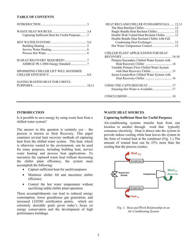
WASTE HEAT SOURCES Capturing Sufficient Heat for Useful Purposes Air-conditioning systems transfer heat from one location to another through work that typically consumes electricity. Heat is drawn into the system to provide indoor cooling while heat leaves the system in the form of wasted heat at the condenser (Fig. 1.) The amount of wasted heat can be 25% more than the cooling that the process creates.
Fig. 1. Heat and Work Relationship in an Air-Conditioning System

4
Equation 4 Total COP for Heat Recovery + Chilled Water
The ability to capture and use this waste heat is known as heat recovery, since the waste heat is recovered and used for other purposes, including heating hot water. Although this process is not new, the benefits of heat recovery are even greater today. The use of heat recovery to generate hot water can reduce the total energy needs of a building and, if applied correctly, contribute to LEED® certification of the building. To determine the potential to use this waste heat, the system efficiencies must be understood. A measure of an air conditioning system’s efficiency is known as the Coefficient of Performance, or COP. The COP for a system that produces heat is the ratio of the output heat to the supplied work as shown in Equation 1. In this equation, Q is the useful heat and W is the work consumed. The work comes from electricity consumed by the compressor. From Fig. 1, consider how this system might be used for heat recovery. When capturing the “Heat Out” for a useful purpose, the COP equation would be represented by Equation 2.
However, a heat recovery system not only produces heat, it also produces cooling. Instead of the traditional air conditioning system, consider a system that produces hot water and the additional benefit of chilled, cold water. So, the COP equation to measure efficiency of producing chilled water can be expressed as shown in Equation 3. But with heat recovery systems, the benefit of hot and cold water can be realized. So, the equation that quantifies the combined benefit of hot and cold water can be expressed as shown in Equation 4. This combined efficiency can contribute to reducing the whole building energy consumption while influencing the number of LEED-NC EAc1 points for LEED certification. Systems that generate sufficient useful heat for both heating and cooling purposes are entirely possible. In fact, heat recovery systems can generate hot and chilled water simultaneously for use within the building or for process applications.
Equation 1 Coefficient of Performance
Equation 2 Coefficient of Performance for Heating
Equation 3 Coefficient of Performance for Cooling

5
Fig. 2. Building Heating Plant Sizing Summary from Carrier HAP version 4.3
HOT WATER SYSTEMS How can the recovered heat be used? Heat from hot water can be used for many purposes in the building or for process applications. In particular, hot water can be used for heating the building, heating service water or as part of a manufacturing or industrial process. There are many examples of each of these heating needs. However, before the appropriate system is considered for these needs, certain design criteria should be understood for each of these applications. Keep in mind that ASHRAE 90.1-2004 requirements for building heat and service hot water differ, so a thorough understanding of the standard is essential prior to designing the system. Building Heating Heating within the building can be achieved in many different ways, from radiant heating sources or reheat to hot water coils installed as part of an air-handling system, and many other means in between. Most importantly, the hot water temperature, flow (in gallons per minute or GPM) and capacity (expressed in Btu/hr) must be fully understood in light of the dynamic heat transfer effects that the building will experience throughout the year. Fluctuations in outdoor temperature; the ever changing loads from solar gains caused by the sun and internal heat sources such as lights, office equipment, and people; and the all important load from ventilation air must be understood and appropriately considered. Load estimating programs that evaluate the building’s thermal performance throughout the entire year can help the system designer better understand the thermal dynamic forces influencing the heating needs. A program such as Carrier’s Hourly Analysis Program (HAP) can help evaluate the heating load from an HVAC system perspective [1] (Fig. 2). Understanding the appropriate hot water temperature needs for building heating purposes is important. Most reheat and building heat applications do not need 130 to 140 F to perform satisfactorily. As discussed later in this paper, operating the reclaim chiller at higher leaving condenser water temperature (LCWT) increases lift and reduces chiller plant efficiency. According to the 2004 ASHRAE Systems and Equipment Handbook, Applied Heat Pump and Heat Recovery Systems, p. 8.20 "For typical buildings, chillers normally provide hot water for space heating at 105º to 110ºF (40.6 to 43.3ºC)." In many VAV (variable air volume) reheat applications, 105 F hot water can be used very
effectively by simply specifying a 2-row reheat coil instead of a 1-row coil. So, elevated hot water temperatures may not be necessary for building heating applications. Lower temperatures will maximize chiller plant efficiency while minimizing system energy consumption. To further understand the building heating load requirements and the potential for a heat recovery system, the monthly or even hourly heating loads should be considered. Figure 3 hows a typical hot water boiler plant load for an office building in Chicago. This information is necessary to determine when heating and cooling loads occur. A program like HAP can help estimate the times when these loads occur.
Fig. 3. Hourly Building Heating Plant Results from Carrier HAP version 4.34

6
However, the heating load is only half of the required heat that can be satisfied by a heat recovery system. The building cooling loads must also be evaluated. An example of typical cooling loads for the same building is shown in Fig. 4.
The designer’s challenge is to determine when both heating and cooling loads exist and how best to capture the heat from a heat recovery system to maximize the benefit of such a system. For building heating applications, some of the best opportunities for heat recovery exist when the building operates 24 hours per day, with high internal cooling loads that may also require heating for perimeter zones. Casinos, hospitals, and full service hotels are some of the likely candidates. Service Water Heating Service water needs vary widely with the building type, occupancy and internal processes such as laundry, dish washing and food preparation. Many design references are available to help the mechanical engineer better understand the maximum demand for hot water. However, it is the design engineer’s responsibility to recognize, understand and properly apply all appropriate codes and local regulations to the plumbing system design. Accurate sizing of the service water heater and the source for the heat is essential to ensure an adequate supply of hot water for all fixtures, all the time. Nationally recognized and/or code approved demand flow rates (typically expressed in gallons per hour, GPH) and demand factors must be understood to properly size these systems. Hot water demand flow rates, based on the building or facility type and the calculated results, should include probable maximum demand in GPH, the required water heater output in Btu/hr, and any required storage tank capacity in gallons.
Some codes require the hot water supply to be sufficient to satisfy the continuous and peak hot water demands of the establishment. If ASHRAE 90.1-2004 criteria is used, tempering the service hot water from “street” temperatures to 85 F would be sufficient. However, most chiller-based heat recovery equipment can produce water temperatures of approximately 120 to 135 F, which is far in excess of the ASHRAE criteria and possibly more useful from a service water perspective. Regardless of temperature, the heat recovery system must accommodate the continuous and peak hot water demands while providing a controlled source of service hot water. Further information on this topic is discussed later in this white paper. Potable water, or water intended to be consumed through drinking by humans, must be of sufficient quality to serve as drinking water whether it is used as such or not. As a result, this water must be protected from contamination from potentially harmful sources. Many codes require the separation of the potable hot water source from non-potable sources by means of a double-wall vented air gap in the heat exchanger as a minimum. This would minimize the risk of internal leakage and cross-contamination between the two fluids. Other means exists to meet the code intent. The design engineer must consider the code requirements before proceeding with the system design. Process Hot Water Process hot water can come from many different sources and be used for many applications. From a plastic injection molding machine pre-heater to a swimming pool heater, process heating requirements can vary with each application. The information commonly used to design the heat recovery system is very similar to the building heating and service hot water applications described above: the hot water flow, temperature and capacity must be understood to support the process heating needs. As we have seen, there are many different potential uses for the hot water generated by a heat recovery system, each with its own unique requirements and design criteria. Next let’s explore how to best capture the useful heat from a heat recovery system while minimizing wasted heat reducing energy consumption, and maximizing the chiller plant efficiency.
Fig.4. Typical Hourly Cooling Coil Loads

7
IS HEAT RECOVERY REQUIRED? ASHRAE 90.1-2004 Energy Standard The current ASHRAE 90.1-2004 Energy Standard Section § 6.5.6.2 Heat Recovery for Service Water Heating requires heat recovery from the condenser side of water-cooled systems for preheating service hot water in large 24-hour facilities [2]. There are a few exceptions identified in this standard; the design engineer is encouraged to closely examine this standard and other codes associated with the project to completely understand the content and intent. Systems seeking to meet the intent of ASHRAE 90.1-2004 can do so with a plate frame heat exchanger located in the return condenser water as shown in Fig. 5. The ability to obtain 85 F pre-heated service water is entirely possible but it is a function the leaving condenser water temperature (LCWT) from the chiller plant. Keep in mind, the LCWT is a function of the outdoor ambient wet-bulb temperature, condenser flow rate and the chiller load. Since a minimum of 85 F service water during peak conditions is required to meet the intent of the standard, the system must produce LCWTs slightly
above 85F. However, elevating the LCWT will increase the chiller lift, reduce the chiller efficiency and increase the chiller plant energy consumption. This is not a favorable condition. These conditions must be understood to determine the energy benefit for this application. One potential benefit of this design is that colder condenser water could be sent to the tower leading to lower tower energy consumption. In addition, the energy consumption for service hot water preheating is reduced. However, the trade off between these benefits must be weighed against elevated LCWT, higher lift, lower chiller plant efficiency and increased chiller plant energy consumption. With this in mind, projects seeking to maximize LEED-NC EAc1 certification points may choose to apply heat recovery using a method that minimizes building energy consumption. To do so, the designer must determine the best means to capture sufficient heat and convert it into useful purposes without decreasing the chiller plant efficiency.
Fig. 5. Pre-Heat of Service Hot Water with Condenser Water Heat Exchanger
8
MINIMIZING CHILLER LIFT WILL MAXIMIZE CHILLER EFFICIENCY
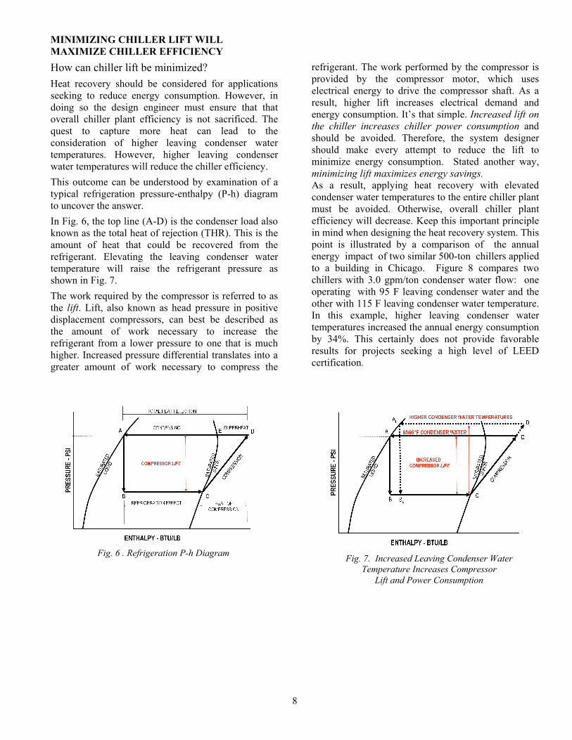
How can chiller lift be minimized? Heat recovery should be considered for applications seeking to reduce energy consumption. However, in doing so the design engineer must ensure that that overall chiller plant efficiency is not sacrificed. The quest to capture more heat can lead to the consideration of higher leaving condenser water temperatures. However, higher leaving condenser water temperatures will reduce the chiller efficiency. This outcome can be understood by examination of a typical refrigeration pressure-enthalpy (P-h) diagram to uncover the answer. In Fig. 6, the top line (A-D) is the condenser load also known as the total heat of rejection (THR). This is the amount of heat that could be recovered from the refrigerant. Elevating the leaving condenser water temperature will raise the refrigerant pressure as shown in Fig. 7. The work required by the compressor is referred to as the lift. Lift, also known as head pressure in positive displacement compressors, can best be described as the amount of work necessary to increase the refrigerant from a lower pressure to one that is much higher. Increased pressure differential translates into a greater amount of work necessary to compress the
refrigerant. The work performed by the compressor is provided by the compressor motor, which uses electrical energy to drive the compressor shaft. As a result, higher lift increases electrical demand and energy consumption. It’s that simple. Increased lift on the chiller increases chiller power consumption and should be avoided. Therefore, the system designer should make every attempt to reduce the lift to minimize energy consumption. Stated another way, minimizing lift maximizes energy savings. As a result, applying heat recovery with elevated condenser water temperatures to the entire chiller plant must be avoided. Otherwise, overall chiller plant efficiency will decrease. Keep this important principle in mind when designing the heat recovery system. This point is illustrated by a comparison of the annual energy impact of two similar 500-ton chillers applied to a building in Chicago. Figure 8 compares two chillers with 3.0 gpm/ton condenser water flow: one operating with 95 F leaving condenser water and the other with 115 F leaving condenser water temperature. In this example, higher leaving condenser water temperatures increased the annual energy consumption by 34%. This certainly does not provide favorable results for projects seeking a high level of LEED certification.
Fig. 6 . Refrigeration P-h Diagram Fig. 7. Increased Leaving Condenser Water Temperature Increases Compressor
Lift and Power Consumption

9
Fig. 8. Energy Comparison: 500 Ton Chiller Plant at 85/95 and 95/115°F Condenser Water Temperature

10
SAVING WASTED HEAT FOR USEFUL PURPOSES
How can a chiller minimize wasted heat? To answer this question, consider the traditional chilled water HVAC system that transfers heat from indoors (at the air handler chilled water coil) to outdoors (at the cooling tower) as shown below. (See Fig. 9.) Heat leaving the system at the cooling tower is “wasted” by being disposed to the outdoors. In fact, energy is actually consumed at the cooling tower and condenser water pumps in disposing this heat into the outdoor environment. What if this “wasted” heat could be minimized and then captured to heat the building or generate hot water? This is entirely possible and can save significant quantities of energy that would otherwise be wasted.
The first step is to minimize the amount of heat that must be pumped to the cooling tower. The easiest way to do this is to specify high-efficiency chillers with full and part load efficiencies surpassing ASHRAE 90.1-2004 minimum efficiency levels. More efficient chillers simply generate less wasted heat and convert more useful work into producing chilled water. Some variable speed screw chillers on the market today have industry leading full and part load efficiencies as low as 0.53 and 0.33 kW/ton, respectively, at ARI 550/590 conditions. When applied in a series counterflow plant, the full and part load efficiencies can be even better – 0.49 and 0.29 kW/ton! These chillers should be considered for projects seeking to minimize “wasted” heat and reduce energy consumption for LEED® certification of the building.
Fig. 9. Chilled Water HVAC System
11
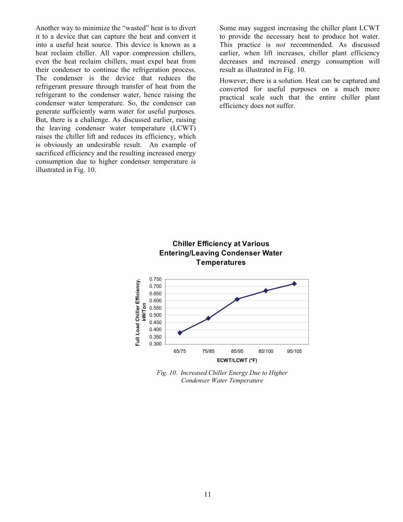
Another way to minimize the “wasted” heat is to divert it to a device that can capture the heat and convert it into a useful heat source. This device is known as a heat reclaim chiller. All vapor compression chillers, even the heat reclaim chillers, must expel heat from their condenser to continue the refrigeration process. The condenser is the device that reduces the refrigerant pressure through transfer of heat from the refrigerant to the condenser water, hence raising the condenser water temperature. So, the condenser can generate sufficiently warm water for useful purposes. But, there is a challenge. As discussed earlier, raising the leaving condenser water temperature (LCWT) raises the chiller lift and reduces its efficiency, which is obviously an undesirable result. An example of sacrificed efficiency and the resulting increased energy consumption due to higher condenser temperature is illustrated in Fig. 10.
Some may suggest increasing the chiller plant LCWT to provide the necessary heat to produce hot water. This practice is not recommended. As discussed earlier, when lift increases, chiller plant efficiency decreases and increased energy consumption will result as illustrated in Fig. 10. However, there is a solution. Heat can be captured and converted for useful purposes on a much more practical scale such that the entire chiller plant efficiency does not suffer.
Fig. 10. Increased Chiller Energy Due to Higher Condenser Water Temperature
Chiller Efficiency at Various Entering/Leaving Condenser Water
Temperatures
0.3000.3500.4000.4500.5000.5500.6000.6500.7000.750
65/75 75/85 85/95 85/100 95/105
ECWT/LCWT (°F)
Full
Load
Chi
ller E
ffici
ency
, kW
/Ton

12
HEAT RECLAIM CHILLER FUNDAMENTALS The Heat Reclaim Chiller The heat reclaim chiller generates high pressure refrigerant within the condenser that can be used to produce higher temperature condenser water. The heat reclaim chiller is very similar to a conventional “cold water” chiller, but modified to optimize the heat recovery performance. These modifications include optimized compressor motors and supporting electrical systems, a heat recovery condenser bundle for each refrigerant circuit and a leaving condenser water temperature control system. As previously described, the hot water requirements can vary considerably, given the unique heat, service water heating, and process hot water demand of each building. There are several types of heat reclaim machines available to meet these needs: Single Bundle Heat Reclaim Chiller This packaged chiller, shown in Fig. 11, is used where leaving water temperatures of up to 120 F are needed for non-potable water applications, such as building heating and process water systems. With a packaged chiller, the on-board control system maintains the “hot” water temperature leaving the condenser while simultaneously producing a source of chilled water.
Double Wall Vented Heat Reclaim Chiller The double wall vented heat reclaim chiller can produce water temperatures up to 135 F. However, these chillers may be used for potable water applications due to the double wall vented heat exchanger design if permitted by the local building codes. The heat exchanger has an air gap to separate the potable water from the refrigerant thus minimizing the potential for potable water contamination. The configuration shown in Fig. 12 uses a desuperheater to produce “hot” potable water. The desuperheater is located in the blue box adjacent to the compressor/cooler. It extracts the high pressure, high temperature heat from the refrigerant to “desuperheat” it to a lower pressure refrigerant. In doing so, hot water is produced. With desuperheating, the amount of heat is less than what could be extracted with a single bundle heat reclaim chiller. Since full condensing does not occur in the desuperheater, the refrigerant vapor must be piped to a separate refrigerant heat exchanger for the remaining condensing process to occur. This process can take place in a remote water-cooled or air-cooled condenser.
Fig. 11. Carrier’s Heat Reclaim Chiller Fig. 12. Heat Reclaim Chiller with Double Wall
Vented Desuperheater
13
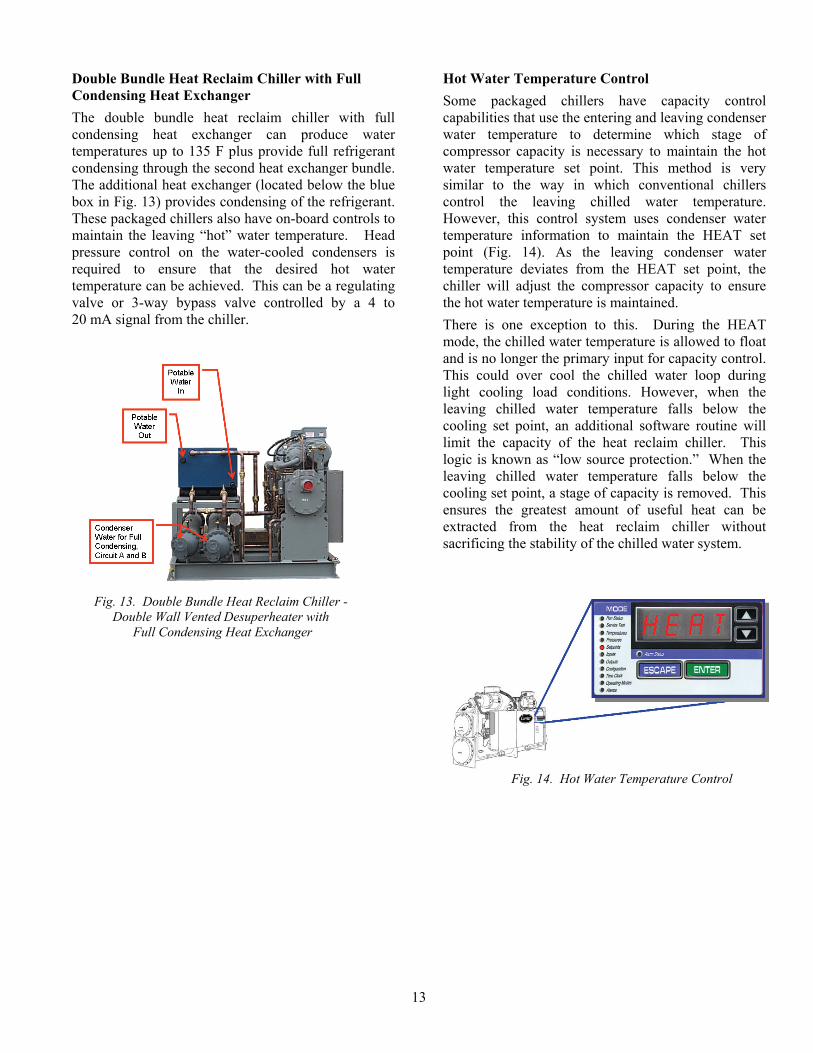
Double Bundle Heat Reclaim Chiller with Full Condensing Heat Exchanger The double bundle heat reclaim chiller with full condensing heat exchanger can produce water temperatures up to 135 F plus provide full refrigerant condensing through the second heat exchanger bundle. The additional heat exchanger (located below the blue box in Fig. 13) provides condensing of the refrigerant. These packaged chillers also have on-board controls to maintain the leaving “hot” water temperature. Head pressure control on the water-cooled condensers is required to ensure that the desired hot water temperature can be achieved. This can be a regulating valve or 3-way bypass valve controlled by a 4 to 20 mA signal from the chiller.
Hot Water Temperature Control Some packaged chillers have capacity control capabilities that use the entering and leaving condenser water temperature to determine which stage of compressor capacity is necessary to maintain the hot water temperature set point. This method is very similar to the way in which conventional chillers control the leaving chilled water temperature. However, this control system uses condenser water temperature information to maintain the HEAT set point (Fig. 14). As the leaving condenser water temperature deviates from the HEAT set point, the chiller will adjust the compressor capacity to ensure the hot water temperature is maintained. There is one exception to this. During the HEAT mode, the chilled water temperature is allowed to float and is no longer the primary input for capacity control. This could over cool the chilled water loop during light cooling load conditions. However, when the leaving chilled water temperature falls below the cooling set point, an additional software routine will limit the capacity of the heat reclaim chiller. This logic is known as “low source protection.” When the leaving chilled water temperature falls below the cooling set point, a stage of capacity is removed. This ensures the greatest amount of useful heat can be extracted from the heat reclaim chiller without sacrificing the stability of the chilled water system.
Fig. 13. Double Bundle Heat Reclaim Chiller - Double Wall Vented Desuperheater with
Full Condensing Heat Exchanger
Fig. 14. Hot Water Temperature Control

14
CHILLER PLANT APPLICATIONS FOR HEAT RECOVERY
There are several means to configure and control a heat recovery system. Each of these chiller plant configurations will: • Capture sufficient heat for useful purposes • Minimize lift and maximize chiller efficiency • Control the hot water temperature without
sacrificing stable chiller plant operation Primary/Secondary Chilled Water System with Heat Recovery Chiller This is a conventional primary/secondary chilled water system with a small capacity heat recovery chiller installed in parallel with the chiller plant (Fig. 15). This configuration minimizes the chiller plant lift and maximizes energy efficiency while allowing direct control of both the hot and chilled water temperatures. The heat recovery chiller produces a base load of chilled water while generating hot water controlled to
the HEAT set point temperature. The heat reclaim chiller offsets the main chiller plant load by providing the base load of chilled water before it enters the primary chillers. Under base load operation, the heat reclaim chiller will provide chilled water to the secondary loop. The “low source protection” feature of the heat reclaim chiller ensures the chilled water temperature will not fall below the cooling set point temperature. This feature ensures stable chiller plant operation while providing a controlled source of hot water. If the chilled water temperature can not be satisfied by the heat reclaim chiller, the first chiller in the primary loop can be energized to provide the necessary chilled water temperature thus maintaining the secondary loop water conditions. This configuration provides a stable source of controlled hot water and a base load of chilled water without affecting the main chiller plant efficiency.
Fig. 15. Primary/Secondary Chilled Water System with Heat Recovery Chiller [3]

15
Variable Primary Flow Chilled Water System with Heat Recovery Chiller
A variable primary flow system, excluding the benefits available from heat reclaim, can offer energy savings beyond other chiller plant configurations. One such study found that “variable flow, primary-only systems reduced total annual plant energy by 3 to 8-percent, first cost by 4 to 8-percent, and life cycle cost by 3 to 5-percent relative to conventional constant primary flow/variable secondary flow systems.” [4] Several plant and load variables contribute to these savings, but overall these systems should be considered when low energy solutions are desired. This system works much the same as the primary/secondary system previously described with the heat reclaim chiller providing a base load of chilled water for the primary chiller plant (Fig. 16). On a call for cooling to maintain the primary loop chilled water temperature, the heat reclaim chiller would be
energized as the first stage of cooling. The control valve located upstream of the heat reclaim chiller would open, flow would be proven at the chiller through its chilled water flow sensor, and the chiller would be energized to maintain the HEAT set point temperature. At the same time, the heat reclaim chiller’s “low source protection” feature will ensure that chilled water is provided at a temperature that is not less than the cooling set point temperature. Ideally, the heat reclaim chiller provides a base load of chilled water to the main chiller plant and it would control the hot water temperature based on its HEAT set point. This ensures a controlled source of hot water is provided when the heat reclaim chiller is operating and a base load of chilled water is provided to augment the main chiller plant.
Fig. 16. Variable Primary Flow Chilled Water System with Heat Recovery Chiller

16
Series Counterflow Chilled Water System with Heat Recovery Chiller
The series counterflow application is yet another means to save even more energy (Fig. 17). Variable speed screw chillers offer precise capacity control under varying return water flow and temperature conditions while providing exceptional full and part load efficiency [5][6]. These chillers are ideal for this application since the instabilities associated with surge in centrifugal chillers are not present. Screw chillers with VFD (variable frequency drive) speed control respond exceptionally well to variations in load and head. However, other chiller types can also benefit from higher overall chiller plant efficiency offered by the series counterflow arrangement. This system takes advantage of the lower lift provided by smaller differences between the leaving chilled water temperature and the leaving condenser water temperature. The series counterflow plant benefits from significantly lower lift and improved overall
chiller plant efficiency. As with the previously described primary/secondary and primary variable flow applications, the first stage of cooling is provided by the heat reclaim chiller. On a call for cooling from the primary chilled water loop, the heat reclaim chiller provided the first stage of cooling while providing a controlled source of hot water based on its HEAT set point temperature. At the same time, the heat reclaim chiller’s “low source protection” feature will ensure that chilled water is provided at a temperature that is not less than the cooling set point temperature. If additional cooling is needed to maintain the primary loop chilled water temperature, the series counterflow chiller plant would be energized. At the same time, the heat reclaim chiller would continue to control the hot water temperature based on its HEAT set point and provide a base load of chilled water.
Fig. 17. Series Counter-Flow Chilled Water System with Heat Recovery Chiller

17
USING THE CAPTURED HEATEnsuring Hot Water is Available The heat reclaim chiller can produce water temperatures up to 135 F when it is operating. When available, this can be sufficiently warm enough to satisfy many applications. However, some applications may need to ensure that a source of hot water warmer than 135 F is always available. When the building cooling load is satisfied, the heat reclaim chiller must shut off to ensure the chilled water loop is not over-cooled. At this point, hot water will not be generated by the heat reclaim chiller. To ensure that hot water is always available at the necessary temperature, a system similar to Fig. 18 should be considered. This system can capture heat from the heat reclaim chiller when it is available and provide hot water at a temperature needed for the specific application. The benefit of preheating the cold make-up water can be realized when the heat reclaim chiller is operating. Many commercial potable water systems require hot water to be circulated throughout the building to ensure that hot water is immediately available when the hot water faucet is opened. To accomplish this, a circulating pump distributes hot water throughout the building. Figure 18 shows how to pipe the heat reclaim chiller into this type of circulated hot water system. This system can be used for potable water applications since a double wall heat exchanger is provided with the heat reclaim chiller. It is important to size the preheat storage tank to account for the recovery time of the heat reclaim chiller. The recovery time is a function of the storage tank volume, cold water make-up rate and temperature and the heating capacity of the heat reclaim chiller.
Notice the location of the tank piping connections. Thermal stratification or improper thermal mixing within these tanks can lead to poor hot water temperature control. The location of the piping connections must ensure thorough thermal mixing within the tanks. The heat reclaim supply should enter the water heater tank approximately 1/3 down from the top of the tank. The interconnecting pipe between the water heater tank and the preheat storage tank should connect as low as possible to the water heater tank and enter the top of the preheat storage tank. Flow in this pipe can go either way depending on the rate of hot water draw from the system and the heat reclaim water flow from the heat reclaim chiller. To ensure proper mixing, it is recommended that the heat reclaim water pump between the preheat storage tank and the heat reclaim chiller remain on at all times. The heat reclaim return piping should connect as low as possible to the preheat storage tank. This is suggested to ensure suitable mixing in the preheat storage tank. A back-up water heater must also be provided to ensure a controlled source of hot water is available during times when the heat reclaim chiller is not operating. The back-up heater can be a conventional water heater, hot water boiler or steam converter. The mixing valve is necessary to ensure the proper temperature water is distributed to the circulated hot water system. This system ensures that the cold make-up water is preheated by the hot water generated by the heat reclaim chiller and the hot water temperature supplied to the heat load is controlled.
Fig. 18. Circulated Potable Water Heating S ystem
18
CONCLUSIONS Capturing useful heat is possible with appropriate equipment applied to meet the hot water and chilled water system needs. There are several means to meet the intent of ASHRAE 90.1-2004 while maximizing LEED-NC certification points. Heat reclaim systems are certainly practical and available with today’s technology. These systems also ensure: • Sufficient heat is captured for useful purposes • Lift is minimized and chiller efficiency is
maximized • A controlled source of hot water with stable
chilled water system operation is provided A properly designed heat recovery system must ensure: 1. Accurate determination of the peak hot water
usage. 2. Reasonable recovery time for the heat reclaim
chiller to make hot water. This is a function of the size of the storage tank, the cold water make-up rate and temperature and the heating capacity of the heat reclaim chiller.
3. Heat reclaim chiller properly sized for heating purposes. Do not oversize the chiller. An oversized heat reclaim chiller will short cycle under part load conditions and lead to poor hot water temperature control and reduced chiller life.
4. Properly sized hot water storage tank(s) to accommodate the necessary recovery time for hot water storage and ensure stable hot water temperature control. A minimum active loop volume of 6.0 to 10.0 gallons/ton of heating is required. The active loop volume should include the condenser or desuperheater volume, heat reclaim piping, water heater tank, and preheat storage tank.
5. Proper piping connection locations for the storage tanks. Multiple pipe connections may be necessary to overcome tank thermal gradients. The connection locations must promote thorough mixing in the tank to ensure the entire tank volume can contribute to the 6.0 to 10.0 gallons/ton minimum loop volume. Proper blending of the cold make-up water with the circulated hot water and the heat reclaim water is essential for stable hot water temperature control.
6. Integrated back-up heat provided for times when the heat reclaim chiller is not operating. This back-up can be a conventional water heater, hot water boiler or steam converter. Regardless of the source of back-up heat, it must be sized to accommodate the system heating load when the heat reclaim chiller can not provide sufficient heat to maintain the hot water storage tank temperature.
7. Storage tank arrangements for integrating recovered pre-heated water from main chiller heat rejection with the primary heated water from the heat reclaim chiller.
Experience has proven that the above recommendations are essential for proper heat reclaim chiller operation and stable hot water temperature control. These recommendations must be followed to avoid chiller short-cycling, unstable hot water temperature control, poor thermal mixing in the storage tanks, and improper integration of the back-up heating system. It is important to understand how to design the heat reclaim system to meet the heating requirements of the building or process. Specifying the appropriate equipment to serve these needs is also important when a controlled source of hot water is desired. There are several chiller plant configurations that will accomplish this goal. Equipment must be specified that can provide a controlled source of recovered heat for hot water. On-board chiller controls can maintain the hot water set point temperatures without sacrificing efficiencies of the entire chilled water plant. The combination of captured heat with optimum chiller plant efficiency will minimize energy consumption and maximize LEED-NC certification points.

19
References: 1. The Benefits of System – Based Design,
James Pegues, Sr. HVAC Systems Engineer, Carrier Software Systems, Carrier Corporation, Syracuse, New York, April, 2002
2. 90.1 User’s Manual, ANSI/ASHRAE/IESNA
Standard 90.1-2004, American Society of Heating, Refrigerating and Air-Conditioning Engineers, Inc., Atlanta, GA USA
3. Diagrams are for illustration purposes only.
System design requirements remain the sole responsibility of the design engineer.
4. Variable Primary Flow Chilled Water Systems:
Potential Benefits and Application Issues Final Report, Volume 1, March 2004, Bahnfleth, and Peyer, Air-Conditioning and Refrigeration Technology Institute, ARTI-21CR
5. Carrier’s 23XRV variable speed screw chillers
have exceptional plant efficiencies. When applied in a series counter-flow plant, efficiencies can reach 0.49 kW/ton for full load operation and part load IPLV of 0.29 kW/ton.
6. Consult chiller manufacturer’s application data for
minimum and maximum cooler flow requirements and flow variation rate limits.

HEAT RECOVERY FROM AIR-COOLED CHILLERS Applications for Heat Reclaim Chillers
May 2009


3
TABLE OF CONTENTS INTRODUCTION ................................................................3 MAXIMIZING THE EFFICIENCY OF GENERATING HOT WATER ........................................ 4,5 THE AIR-COOLED CHILLER WITH HEAT RECLAIM CAPABILITY................................................ 5,6 APPLICATION CONSIDERATIONS.................................7 HOT WATER APPLICATIONS IN BUILDINGS ........ 7-12 Specific Applications.....................................................8 Evaluation of Potential Application.............................12
ENERGY SAVINGS ANALYSIS....................................13 EQUIPMENT SELECTION GUIDELINES ....................13 SYSTEM DESIGN CONSIDERATION .................... 14-15 Multiple Chiller System with Heat Reclaim for Building Heating .................................................14 CONCLUSION.................................................................15
INTRODUCTION Why is heat recovery important? Buildings are responsible for 40% of the total U.S.A. primary energy consumption [1] and 43% of the energy consumed in commercial buildings is used for space and water heating [2] as illustrated in Fig. 1. If a more efficient means of providing heat could be implemented it would represent a tremendous
opportunity to reduce energy consumption in buildings and thus reduce total energy consumption in the U.S.A. This white paper explores a more efficient means of generating hot water through the application of air-cooled chiller systems with heat reclaim capabilities to reduce the energy consumption in buildings.
Fig. 1. 2003 Commercial Buildings Energy Consumption Survey - Major Fuel Consumption by End Use for All Buildings
4
MAXIMIZING THE EFFICIENCY OF GENERATING HOT WATER
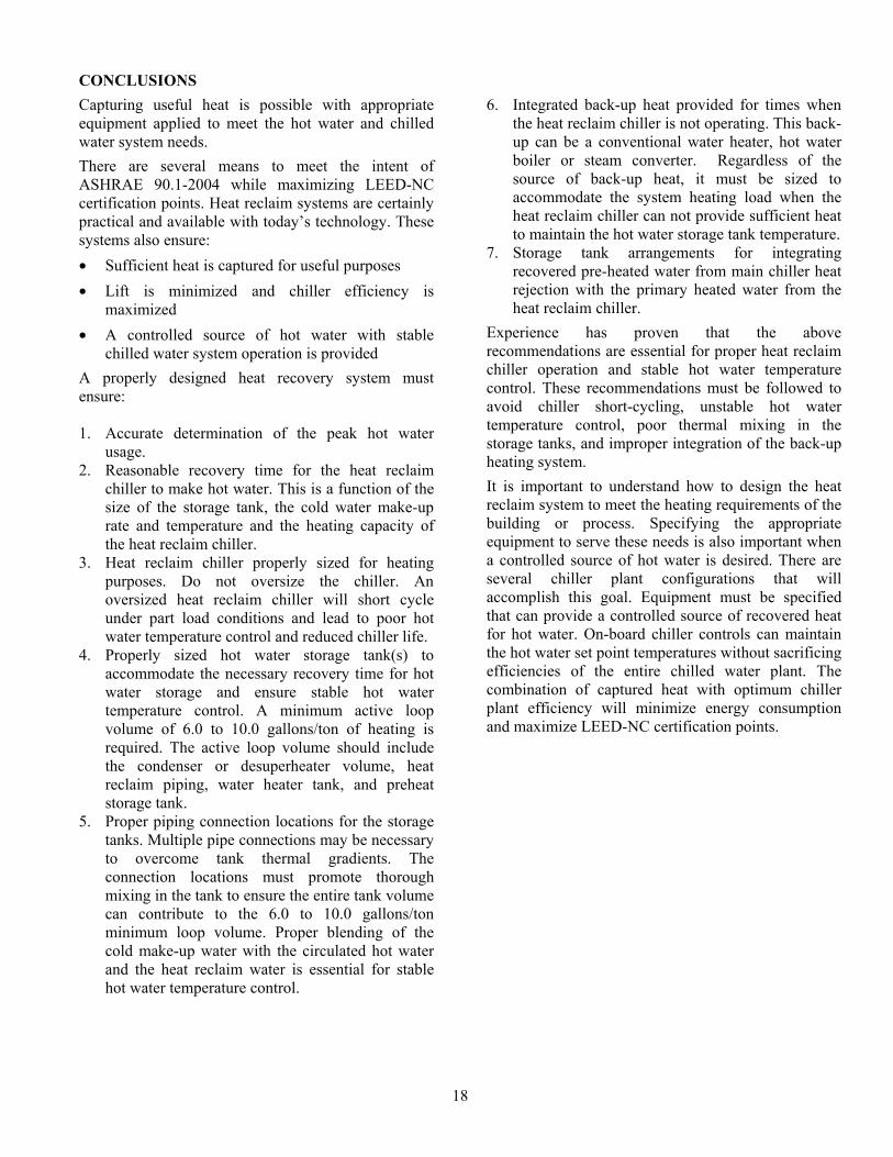
Hot water has been created in very much the same way for many years. Fossil fuels are combusted around a metal vessel filled with water. More recently, electric elements have been immersed in a water vessel to heat the water. When heating with fossil fuels, efficiencies can reach more than 90% [3] in a condensing-type boiler and upwards of 100% with electric immersion water heaters. These efficiencies represent a coefficient of performance (COP) of 0.90 and 1.0 respectively. Is it possible to generate hot water at a COP greater than 1.0? The answer is yes. Heat recovery captures energy that would otherwise be wasted to the atmosphere and converts this energy into useful heat. As shown in Fig. 2, it is possible to capture this “Heat Out” from the condenser and use it to generate hot water. By capturing this heat that would otherwise be wasted, overall system efficiencies can be significantly increased.
Unlike the process of generating heat from combustion or electrically driven water heaters, capturing waste heat from the condenser can result in efficiencies greater than 100%. This achievement is the result of using the heat captured from the condenser plus the cooling effect from the evaporator. When both sources of heat are captured, efficiencies greater than 100% can be realized. In fact, the total COP for heat reclaim from a chiller system for both water heating and cooling purposes can reach over 5.0.
Equation 1 Total COP for Heat Recovery + Chilled Water
Fig. 2. Heat and Work Relationship in an Air-Conditioning System
Expansion Device
5
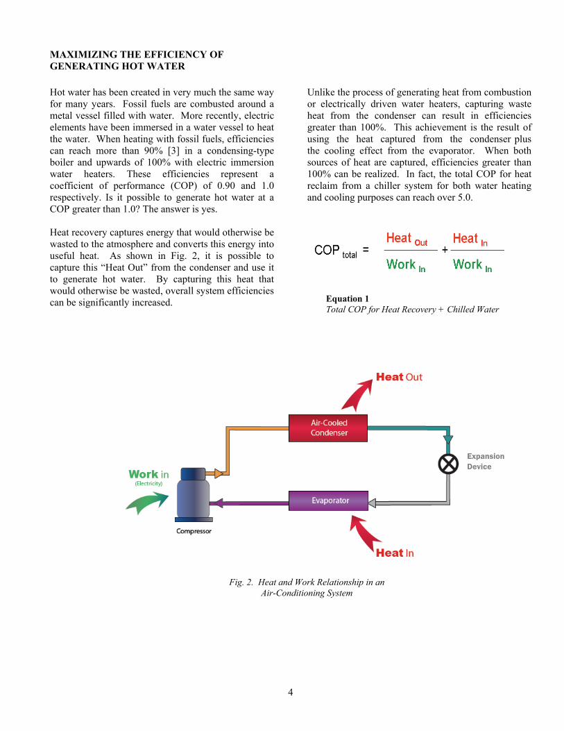
If we look at the performance of a nominal 120-ton air-cooled chiller with heat reclaim we can see the energy advantages based on the total COP. Chiller performance at 44 F leaving chilled water temperature, 2.5 gpm/ton evaporator flow with heat reclaim in operation to produce 121 F entering heat reclaim water temperature and 131 F leaving heat reclaim water temperature:
Cooling Capacity 93.7 tons (329.6 kW) Input Power 159.9 kW Heating Output 1,642 MBH (480.7 kW)
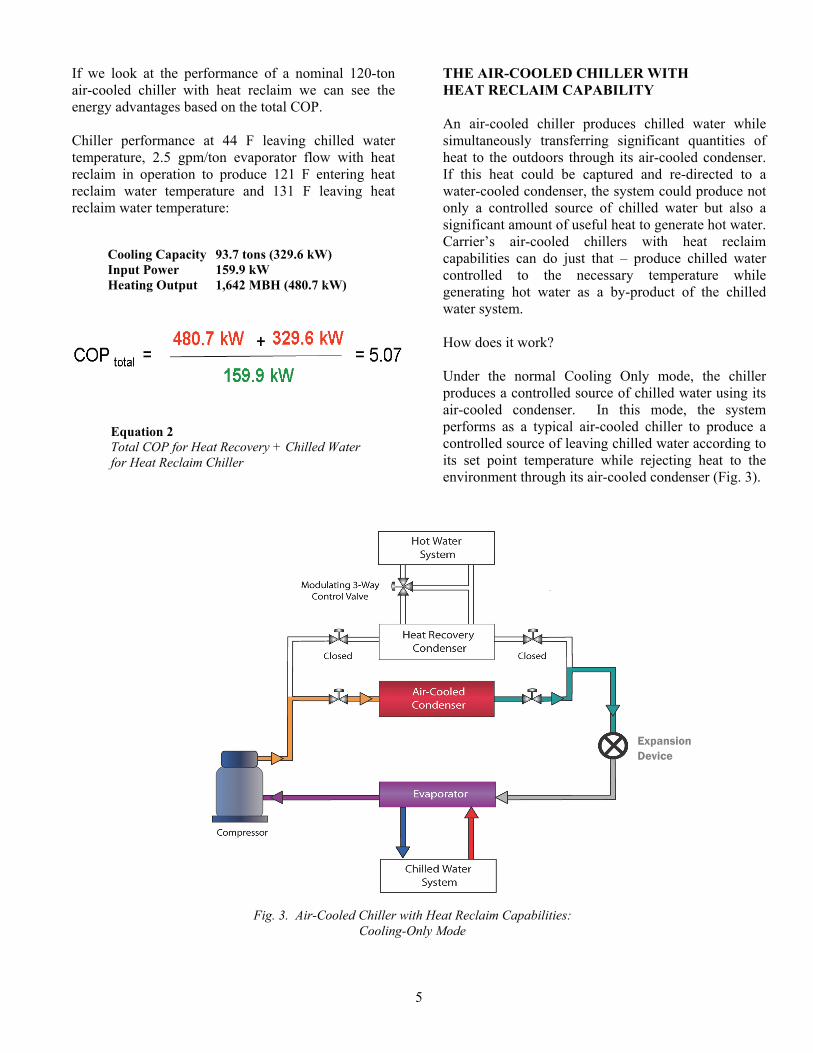
THE AIR-COOLED CHILLER WITH HEAT RECLAIM CAPABILITY An air-cooled chiller produces chilled water while simultaneously transferring significant quantities of heat to the outdoors through its air-cooled condenser. If this heat could be captured and re-directed to a water-cooled condenser, the system could produce not only a controlled source of chilled water but also a significant amount of useful heat to generate hot water. Carrier’s air-cooled chillers with heat reclaim capabilities can do just that – produce chilled water controlled to the necessary temperature while generating hot water as a by-product of the chilled water system. How does it work?
Under the normal Cooling Only mode, the chiller produces a controlled source of chilled water using its air-cooled condenser. In this mode, the system performs as a typical air-cooled chiller to produce a controlled source of leaving chilled water according to its set point temperature while rejecting heat to the environment through its air-cooled condenser (Fig. 3).
Fig. 3. Air-Cooled Chiller with Heat Reclaim Capabilities: Cooling-Only Mode
Equation 2 Total COP for Heat Recovery + Chilled Water for Heat Reclaim Chiller
Expansion Device

6
When an air-cooled chiller is operating in the Heat Recovery mode, there must be a simultaneous need for chilled water and tempered hot water. It is important to note that this chiller will always maintain the leaving chilled water temperature. As a result, the chiller will produce as much hot water as possible while controlling the leaving chilled water temperature. The leaving hot water temperature is a by-product of the cooling cycle. To generate hot water, the entering hot water temperature is compared to the hot water set point, also known as the heat reclaim set point, to determine the number of circuits necessary to maintain entering hot water temperatures. If the entering hot water temperature is below the customer adjustable set point, one refrigeration circuit will automatically change over to Heat Recovery mode
as shown in Fig. 4. The chiller is now operating much like a water-cooled chiller with one circuit and as an air-cooled chiller with the other circuit. Depending on the entering hot water temperature and deviation from set point, the second circuit may also be switched to Heat Recovery mode through the integrated controls. The entering hot water temperature is controlled by the cycling of each refrigerant circuit from the Cooling to the Heat Recovery modes. When the hot water set point is satisfied, the chiller will then transition back to the Cooling Only mode to operate as a conventional air-cooled chiller. The leaving hot water temperature is a function of the entering hot water temperature, hot water flow, and chiller capacity.
Fig. 4. Air-Cooled Chiller with Heat Reclaim Capabilities: Heat Recovery Mode
Expansion Device
7
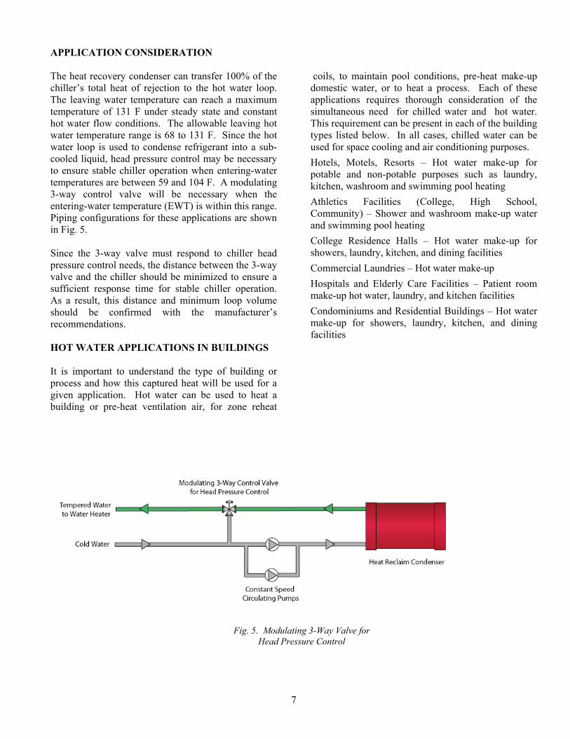
APPLICATION CONSIDERATION The heat recovery condenser can transfer 100% of the chiller’s total heat of rejection to the hot water loop. The leaving water temperature can reach a maximum temperature of 131 F under steady state and constant hot water flow conditions. The allowable leaving hot water temperature range is 68 to 131 F. Since the hot water loop is used to condense refrigerant into a sub-cooled liquid, head pressure control may be necessary to ensure stable chiller operation when entering-water temperatures are between 59 and 104 F. A modulating 3-way control valve will be necessary when the entering-water temperature (EWT) is within this range. Piping configurations for these applications are shown in Fig. 5. Since the 3-way valve must respond to chiller head pressure control needs, the distance between the 3-way valve and the chiller should be minimized to ensure a sufficient response time for stable chiller operation. As a result, this distance and minimum loop volume should be confirmed with the manufacturer’s recommendations. HOT WATER APPLICATIONS IN BUILDINGS It is important to understand the type of building or process and how this captured heat will be used for a given application. Hot water can be used to heat a building or pre-heat ventilation air, for zone reheat
coils, to maintain pool conditions, pre-heat make-up domestic water, or to heat a process. Each of these applications requires thorough consideration of the simultaneous need for chilled water and hot water. This requirement can be present in each of the building types listed below. In all cases, chilled water can be used for space cooling and air conditioning purposes. Hotels, Motels, Resorts – Hot water make-up for potable and non-potable purposes such as laundry, kitchen, washroom and swimming pool heating Athletics Facilities (College, High School, Community) – Shower and washroom make-up water and swimming pool heating College Residence Halls – Hot water make-up for showers, laundry, kitchen, and dining facilities Commercial Laundries – Hot water make-up Hospitals and Elderly Care Facilities – Patient room make-up hot water, laundry, and kitchen facilities Condominiums and Residential Buildings – Hot water make-up for showers, laundry, kitchen, and dining facilities
Fig. 5. Modulating 3-Way Valve for Head Pressure Control

8
Specific Applications Reheat Coils
ASHRAE 90.1-2007 states that simultaneous heating and cooling is prohibited.[4] However, the standard also states several exceptions to this limitation, one of which opens the possibility of heat reclaim from chilled water systems: "Zones where at least 75% of the energy for reheating or for providing warm air in mixing systems is provided from a site recovered energy source (including condenser heat) or site-solar energy source." Therefore, it is entirely possible to design a heat reclaim system for at least 75% or the reheating load while meeting the intent of the standard. Also, the leaving hot water temperatures available from heat reclaim are within the reheat coil performance capabilities.
In many VAV (variable air volume) reheat applications, 105 to 131 F hot water can be used very effectively by simply specifying a 2-row reheat coil instead of a 1-row coil. For these applications, using the reclaimed heat is possible with appropriate design consideration and a suitable quantity of site recovered energy. If higher hot water temperatures are necessary, an auxiliary heating apparatus such as a hot water boiler can be added to the heat reclaim water loop as shown in Fig. 6.
Fig. 6. Auxiliary Heating Apparatus to Boost Heat Reclaim Water Temperatures

9
Potable Domestic Hot Water Make-Up Reclaimed heat may be used to pre-heat the domestic (potable) hot water make-up. However, many building codes require the protection of the potable water supply from contamination from toxic heat transfer fluids. For example, the New York State Plumbing Code states, “Heat exchangers utilizing an essentially toxic transfer fluid shall be separated from the potable water by double-wall construction. An air gap open to the atmosphere shall be provided between the two walls.”[5] Compliance with local codes is the responsibility of the design professional.
Specifying a double-wall vented heat exchanger is one way to meet the intent of the code. These heat exchangers are available on some heat reclaim chillers. However, another method that can meet the intent of separating the heat transfer fluids from the potable water source is to use an intermediate heat exchanger located between the potable water source and the reclaimed hot water as shown in Fig. 7.
Fig. 7. Intermediate Heat Exchanger between Potable Water and the Heat Reclaim Condenser

10
Swimming Pool and Spa Heating Spa water temperatures must be limited to 104 F according to some codes [6] and the desired temperature for swimming pools is 80 F. These temperatures are well within the operating range of many heat reclaim systems. One of the unique design challenges for this application is protecting the heat reclaim condenser from the corrosive effects of the pool or spa water. High concentrations of chlorine, bromine, and sodium chloride disinfectants can cause corrosion damage to the metallic components of the heat reclaim condenser. The use of an intermediate heat exchanger with suitable corrosion resistant construction can help overcome this design issue as shown in Fig. 8. Laundry Water Heating Commercial laundries, also known as “on premise laundries,” or industrial laundries, use significant quantities of water for washing and rinsing purposes. [7] There are many facilities in which laundries are found, including motels, hotels, nursing homes, prisons, universities, and hospitals. Tremendous
energy savings can be realized by pre-heating the vast quantities of make-up water used by these facilities. NOTE: Many packaged laundry systems have self contained heat recovery, since the waste water discharge can be sufficiently warm enough to preheat the make-up water. Application of the heat reclaim chiller may be limited when the packaged laundry system has an integral heat recovery system. Be sure to confirm the manufacturer’s recommended operating limits of the chiller EWT for the application served. Carrier’s 30RB air-cooled chiller with heat reclaim capabilities is limited to a continuous EWT of 59 F when head pressure control is used. The make-up water coming from the street water main or water well can be as cold as 50 F, or even lower in some climates. This is colder than the minimum entering-water temperature (EWT) limitations for the heat reclaim chiller.
Fig. 8. Intermediate Heat Exchanger between Pool/Spa and the Heat Reclaim Condenser

11
Not only does the heat reclaim condenser provide an abundant quantity of useful heat, it also serves a vital role in the refrigeration process. The condenser EWT influences the head pressure control system of the chiller. If the EWT is too cold, the resulting refrigeration system head pressure can affect proper chiller operation. If the EWT is expected to be between 59 and 104 F, the chiller must take control of the condenser water flow rate to maintain proper head pressure. A modulating 3-way control valve must be provided as shown in Fig 9. When the EWT is between 59 and 104 F, the chiller’s head pressure control system will initiate an analog control signal to modulate the 3-way valve position between 20 to 100% open to regulate the condenser water flow rate and maintain proper head pressure. At no time should the valve allow flow less than 20% of full flow. Snow Melting In mildly cold climates with low to moderate snow fall rates, building processes that require year-round chilled water for cooling purposes can take advantage of the hot water generated by the heat reclaim chiller and use it for snow melting purposes.[8] The greatest
challenge with this application is to ensure that the EWT does not fall below 59 F. Fluid temperatures below this limit can be present when the snow melting system is first activated. As a result, snow melting fluid temperature controls will be necessary to ensure that the EWT is maintained within acceptable limits for the chiller. The modulating 3-way valve head pressure control as described above (see Fig. 9) must be used when the EWT is below 59 F. For a system exposed to cold outdoor conditions in applications where fluid temperatures can be below 32 F an appropriate antifreeze solution must be used. In colder climates, winter soil temperatures can fall well below 59 F which is outside the required operating limits of the heat reclaim chiller. These applications will require an auxiliary heating apparatus, such as a boiler, to ensure that the required operating limits are satisfied. Figure 10 shows the location of the auxiliary heating apparatus to ensure the EWT is sufficiently warm to allow the heat reclaim chiller to operate.
Fig. 9. Make-up Water System with Modulating 3-Way Valve for Head Pressure Control

12
Process Heating It is important to fully understand the cycle rate and temperature needs of the process served by the heat reclaim chiller. Process heating is usually associated with non-potable water applications. However, appropriate measures must be taken if the process water is for potable purposes. This application requires a separation between the heat reclaim condenser and the potable water source by means of an intermediate heat exchanger as previously described. The cyclical nature of many process heating loads can create a challenge for stable heat reclaim chiller operation if not properly addressed. The heat reclaim loop volume, defined as the gallons of fluid in the heat reclaim loop, becomes more important as the process heating loads fluctuate. To overcome these fluctuations, the manufacturer’s minimum loop volume recommendations must be followed. The storage tank, as shown in Fig. 9, can add effective loop volume to the system and help stabilize the leaving water temperature. Kitchen Water/Dishwashing These are potable water applications that will require suitable separation between the heat reclaim condenser and the potable water source by an intermediate heat exchanger. Commercial dish washing can require elevated hot water temperatures above 150 F [9] to meet local plumbing and health codes. As a result, the heat reclaim chiller is best suited for make-up water preheating as previously shown in Fig. 7.
Evaluation of Potential Application The following should be used as a guide to determine if your project is a candidate for Carrier’s heat reclaim solution. This initial evaluation can assess the likelihood of a suitable project given the application criteria for heat reclaim. Simultaneous need for chilled water and hot water? ___YES ___NO Hot water temperatures from the heating system between 59 and 131 F? ___YES ___NO Chilled water load between 60 and 190 tons? ___YES ___NO Hot water load between 770 and 2650 MBH? (for single chiller applications) ___YES ___NO Space for an outdoor chiller ___YES ___NO If the answer is YES to all of the above questions, Carrier’s heat reclaim chiller is a likely candidate for the application. If the cooling or heating loads are greater than those shown above, multiple heat reclaim chillers can be used.
Fig. 10. Auxiliary Heating Apparatus for Snow Melting System

13
ENERGY SAVINGS ANALYSIS There are numerous uses for the recovered heat from the 30RB chiller with heat reclaim. However, an economic assessment should be conducted to determine the financial viability of the system. A simple way to determine the viability of a heat reclaim system is to compare the potential energy cost savings between a conventional hot water boiler and the heat reclaim chiller. The basis of this comparison should include the amount of heat generated, the fuel cost, and operating efficiency of the alternatives. To simplify the analysis, consider the energy cost savings of creating 1,000,000 Btu of heat output between the heat reclaim chiller and several alternative hot water boiler systems. Figure 11 shows a simple analysis to determine the potential energy cost savings comparing these systems. The example in Fig. 11 provides a simple estimate of the potential energy cost savings. A more refined approach in assessing the potential energy costs savings should include the part load performance of the heat machine while operating under the intended
conditions when producing chilled and hot water. Energy analysis programs such as Carrier’s Hourly Analysis Program (HAP v4.4 or later) can help with annual energy cost assessments and also provided information suitable for submission to the USGBC (U.S. Green Building Council) for Leadership in Energy and Environmental Design (LEED®) certification. Carrier’s HAP software (v4.4 or later) has the ability to generate the all important LEED Energy and Atmosphere Credit 1 (EAc1) template data formatted to USGBC’s on-line credit template form. This feature can save substantial time when developing the LEED (v3.0) EAc1 credit forms. EQUIPMENT SELECTION GUIDELINES When choosing a heat reclaim chiller, always follow the manufacturer’s procedure outlined with their selection tools. Carrier’s Packaged Chiller Builder Program (version 3.29h or later) can help make chiller and heat reclaim selections easier.
Fig. 11. Savings Analysis: Heat Reclaim Chiller vs Hot Water Boiler

14
SYSTEM DESIGN CONSIDERATION Multiple Chiller System with Heat Reclaim for Building Heating
Integrated building cooling and heating systems can be achieved with proper attention to the application limits and control requirements of the system components. When seeking to capture heat from the heat reclaim loop, there must be the need for simultaneous cooling and heating. However, the system illustrated in Fig. 12 can operate in the Cooling-Only, Heat Reclaim, or Heating modes to satisfy the building’s HVAC loads. This system is one of many potential ways to capture heat from the heat reclaim chiller for useful purposes. A variable primary flow chilled water system is described below. However, alternative systems such as a primary-secondary chilled water system would also be possible. For either system, the heat reclaim pumps must be enabled by the lead heat reclaim chiller. Also,
the return hot water temperature from the building heating system must be lower than the heat reclaim set point in order for reclaimed heat to be effective. If the storage tank mixed water temperature is between 59 and 104 F, head pressure control from the chiller will be necessary. A modulating 2-way control valve located downstream of each chiller must be controlled by the chiller head pressure control signal. The VFD (variable frequency drive) heat reclaim pump is controlled by system differential pressure. The 2-way valve and VFD pump system is the best way to provide the necessary head pressure control while reducing pump energy. Three-way valves applied to each chiller could be used, but pump energy consumption would be higher.
Fig. 12. Multiple Chiller System with Heat Reclaim for Building Heating

15
The following sequence describes the function of various system components during different operating modes. This system is intended to produce chilled water for building cooling purposes, reclaimed heat to temper the mixed water in the storage tank, and hot water for building heating purposes. Cooling-Only Mode On a call for cooling, the 2-way chilled water valve serving the lead chiller will open and the chilled water pump will provide flow. Variable primary chilled water flow is then provided by the VFD driven chilled water pump controlled in response to a differential pressure signal from the chilled water loop piping. The chiller will control the leaving chilled water temperature based on its set point conditions. The chiller’s air-cooled condensers will condense the refrigerant and the heat reclaim condensers will remain off. As a result, no heat is added to the heat reclaim loop. Building heating is not energized in this mode. If the primary chilled water temperature cannot be maintained by one chiller, the 2-way chilled water valve on the second chiller will open to allow chilled water flow to the second chiller. The second chiller will then be energized to provide a controlled source of chilled water. The third 2-way valve will open and its chiller will provide chilled water when necessary to maintain the primary chilled water loop temperature. Heat Recovery Mode On a call for cooling, the 2-way chilled water valve control, chilled water pump VFD control, and chilled water temperature control will function as described in the “Cooling-Only” mode above. At the same time, the lead chiller will open its heat reclaim modulating 2-way valve to its minimum position and enable the heat reclaim pump to monitor the entering heat reclaim water temperature to determine if heat should be added to the heat reclaim loop. Heat reclaim water flow is provided by the VFD driven pump controlled by a differential pressure signal from the heat reclaim loop piping. The chiller will determine how much heat should be added to the heat reclaim loop based on the deviation from the entering heat reclaim set point temperature. The chiller will reduce the amount of heat added to the heat reclaim loop once the entering water temperature set point conditions have been satisfied. As other chillers are energized in response to increased cooling loads, the heat reclaim 2-way valves will be opened to allow additional heat to be added to the heat reclaim loop. If the entering heat reclaim water temperature is between 59 and 104 F, the heat reclaim
modulating 2-way valve will receive an analog signal from the chiller to regulate the valve position to maintain proper head pressure control. At the same time, the VFD driven heat reclaim pumps will regulate water flow to maintain the system differential pressure. The building heating control system will energize the hot water pumps and auxiliary heater as necessary to maintain the building heating loop temperature. Heating Mode The building heating control system and auxiliary heater, typically a boiler system, will provide all building heating needs. Since no chilled water is needed, the heat reclaim chiller remains off in this mode and no heat is added to the heat reclaim loop. CONCLUSION With the ever growing concerns over escalating energy costs, increased energy consumption, and the resulting impact on the economy and the environment, heat recovery from the chilled water system offers an excellent solution to all of these issues. Capturing heat that would otherwise be wasted and converting it into useful energy can minimize operating cost, reduce energy consumption, and advance the movement toward sustainability. The design professional should fully understand the application needs, system requirements and component capabilities to develop a system to meet the intended goals. Once these needs are fully understood and properly implemented, the energy efficiency and operating benefits can be fully realized. Heat recovery using Carrier’s heat reclaim chiller is an excellent choice when looking for environmentally responsible energy saving solutions. In applications from hotels to hospitals, casinos or universities, for service water heating to building heating, pool heating or preheating domestic water sources, heat reclaim is not only possible but also potentially a very efficient means to reduce energy costs and consumption. The heat reclaim chiller is a wonderful supplement to fossil fueled water heating systems to maximize LEED-NC Energy and Atmosphere credit 1 points and meet or exceed the requirements of ASHRAE 90.1-2007. Whether striving to minimize the operating costs of a facility or reducing the building’s carbon footprint, heat recovery from the chilled water system is entirely possible and practical with Carrier’s 30RB heat reclaim chiller.

16
References:
1. Department of Energy, Buildings Energy Data Book, Buildings Share of U.S. Primary Energy Consumption, 2007, http://buildingsdatabook.eren.doe.gov/TableView.aspx?table=1.1.3
2. Energy Information Administration, 2003 Commercial Buildings Energy Consumption Survey, Table E1A. Major Fuel Consumption (Btu) by End Use for All Buildings, 2003 http://www.eia.doe.gov/emeu/cbecs/cbecs2003/overview1.html
3. James B. Rishel and Benny L. Kincaid, “Reducing Energy Costs with Condensing Boilers and Heat Recovery Chillers,” ASHRAE Journal, (March 2007)
4. ASHRAE Standard - Energy Standard for Buildings Except Low-Rise Residential Buildings, ANSI/ASHRAE/IESNA Standard 90.1-2007, Section § 6.5.2
5. New York State Plumbing Code, §P608.16.3 Heat exchangers (2006)
6. New York State Health Code, Compilation of the Rules and Regulations of the State of New York (NYCRR) Title 10, Volume A, Sub Part 6-1 - Swimming Pools, Section 6-1.29 - Swimming pool design standards, sub-section 14.7.2
7. J. Riesenberger and J. Koeller, Commercial Laundry Facilities (2005)
8. 2007 ASHRAE Handbook – HVAC Applications, Chapter 50, Snow Melting and Freeze Protection, Table 5, Steady State Surface Heat Fluxes and Average Fluid Temperatures for Hydronic Snow-Melting System in Figure 3, page 50.12
9. 2007 ASHRAE Handbook – HVAC Applications, Chapter 49, Service Water Heating, Table 3, Representative Hot-Water Temperatures, page 49.10

VARIABLE FREQUENCYDRIVE
OPERATION AND APPLICATION OFVARIABLE FREQUENCY DRIVE (VFD) TECHNOLOGY
Carrier CorporationSyracuse, New York
October 2005

INTRODUCTION . . . . . . . . . . . . . . . . . . . . . . . . . .2Common VFD Terms
VFD OPERATION . . . . . . . . . . . . . . . . . . . . . . . . . .3
BENEFITS OF VFD . . . . . . . . . . . . . . . . . . . . . . . .4VFD Capacity Control Saves Energy . . . . . . . . . .4Low Inrush Motor Starting . . . . . . . . . . . . . . . . . .5Easy Installation . . . . . . . . . . . . . . . . . . . . . . . . . .5High Power Factor . . . . . . . . . . . . . . . . . . . . . . . .5Low Full Load KVA . . . . . . . . . . . . . . . . . . . . . . .6
HARMONIC DISTORTION AND INDUSTRY STANDARDS . . . . . . . . . . . . . . . . . .6Harmonic Definition . . . . . . . . . . . . . . . . . . . . . . .6What Causes Harmonics? . . . . . . . . . . . . . . . . . . .7Rocks and Ponds . . . . . . . . . . . . . . . . . . . . . . . . . .7Are Harmonics Harmful? . . . . . . . . . . . . . . . . . . .7Understanding IEEE 519 . . . . . . . . . . . . . . . . . . . .7Introduction to Harmonic Terms . . . . . . . . . . . . . .8Mitigating Harmonics . . . . . . . . . . . . . . . . . . . . . .9
TABLE OF CONTENTS
INTRODUCTION
Variable frequency drive (VFD) usage has increaseddramatically in HVAC applications. The VFDs arenow commonly applied to air handlers, pumps,chillers and tower fans. A better understanding ofVFDs will lead to improved application and selec-tion of both equipment and HVAC systems. Thispaper is intended to provide a basic understandingof common VFD terms, VFD operation, and VFDbenefits. In addition this paper will discuss somebasic application guidelines regarding harmonic dis-tortion with respect to industry standards.
Common VFD Terms
There are several terms used to describe devices thatcontrol speed. While the acronyms are often usedinterchangeably, the terms have different meanings.
Variable Frequency Drive (VFD)This device uses power electronics to vary the fre-quency of input power to the motor, thereby con-trolling motor speed.
Variable Speed Drive (VSD)This more generic term applies to devices that con-trol the speed of either the motor or the equipmentdriven by the motor (fan, pump, compressor, etc.).This device can be either electronic or mechanical.
Adjustable Speed Drive (ASD)Again, a more generic term applying to bothmechanical and electrical means of controllingspeed.
This paper will discuss only VFDs.
2

VFD OPERATION
Understanding the basic principles behind VFDoperation requires understanding the three basicsections of the VFD: the rectifier, dc bus, andinverter.
The voltage on an alternating current (ac) powersupply rises and falls in the pattern of a sine wave(see Figure 1). When the voltage is positive, currentflows in one direction; when the voltage is negative,the current flows in the opposite direction. This typeof power system enables large amounts of energy tobe efficiently transmitted over great distances.
The rectifier in a VFD is used to convert incomingac power into direct current (dc) power. One rectifi-er will allow power to pass through only when thevoltage is positive. A second rectifier will allowpower to pass through only when the voltage is neg-ative. Two rectifiers are required for each phase ofpower. Since most large power supplies are threephase, there will be a minimum of 6 rectifiers used(see Figure 2). Appropriately, the term “6 pulse” isused to describe a drive with 6 rectifiers. A VFDmay have multiple rectifier sections, with 6 recti-fiers per section, enabling a VFD to be “12 pulse,”“18 pulse,” or “24 pulse.” The benefit of “multi-pulse” VFDs will be described later in the harmon-ics section.
Rectifiers may utilize diodes, silicon controlled rec-tifiers (SCR), or transistors to rectify power. Diodesare the simplest device and allow power to flow anytime voltage is of the proper polarity. Silicon con-trolled rectifiers include a gate circuit that enables a
microprocessor to control when the power maybegin to flow, making this type of rectifier useful forsolid-state starters as well. Transistors include a gatecircuit that enables a microprocessor to open orclose at any time, making the transistor the mostuseful device of the three. A VFD using transistorsin the rectifier section is said to have an “activefront end.”
After the power flows through the rectifiers it isstored on a dc bus. The dc bus contains capacitorsto accept power from the rectifier, store it, and laterdeliver that power through the inverter section. Thedc bus may also contain inductors, dc links, chokes,or similar items that add inductance, therebysmoothing the incoming power supply to the dc bus. The final section of the VFD is referred to as an“inverter.” The inverter contains transistors thatdeliver power to the motor. The “Insulated GateBipolar Transistor” (IGBT) is a common choice inmodern VFDs. The IGBT can switch on and off sev-eral thousand times per second and precisely controlthe power delivered to the motor. The IGBT uses amethod named “pulse width modulation” (PWM)to simulate a current sine wave at the desired fre-quency to the motor.
Motor speed (rpm) is dependent upon frequency.Varying the frequency output of the VFD controlsmotor speed:
Speed (rpm) = frequency (hertz) x 120 / no. of poles
Example:2-pole motor at different frequencies3600 rpm = 60 hertz x 120 / 2 = 3600 rpm3000 rpm = 50 hertz x 120 / 2 = 3000 rpm2400 rpm = 40 hertz x 120 / 2 = 2400 rpm
3
Fig. 1. AC sine wave
Fig. 2. VFD basics: Existing technology
AC sine wave
-2
-1
0
1
2
0 90 180 270 360

BENEFITS OF VFD
As VFD usage in HVAC applications has increased,fans, pumps, air handlers, and chillers can benefitfrom speed control. Variable frequency drives pro-vide the following advantages:
• energy savings• low motor starting current• reduction of thermal and mechanical
stresses on motors and belts during starts• simple installation• high power factor• lower KVA
Understanding the basis for these benefits will allowengineers and operators to apply VFDs with confi-dence and achieve the greatest operational savings.
VFD Capacity Control Saves Energy
Most applications do not require a constant flow ofa fluid. Equipment is sized for a peak load that mayaccount for only 1% of the hours of operation. Theremaining hours of operation need only a fraction ofthe flow. Traditionally, devices that throttle outputhave been employed to reduce the flow. However,when compared with speed control, these methodsare significantly less efficient.
Mechanical Capacity Control
Throttling valves, vanes, or dampers may beemployed to control capacity of a constant speedpump or fan. These devices increase the head, there-by forcing the fan or pump to ride the curve to apoint where it produces less flow (Figure 3). Powerconsumption is the product of head and flow.Throttling the output increases head, but reducesflow, and provides some energy savings.
4
Pump power ~ flow x head / 39601
Variable Speed Capacity Control
For centrifugal pumps, fans and compressors, theideal fan (affinity) laws describe how speed affectsflow, head and power consumption (Table A).
When using speed to reduce capacity, both the headand flow are reduced, maximizing the energy sav-ings. A comparison of mechanical and speed controlfor capacity reduction (Figure 4) shows that variablespeed is the most efficient means of capacitycontrol.
Fig. 3. Mechanical capacity control
Fig. 4. Comparison of mechanical capacity control and speed capacity control
1 Assumes fluid is fresh water, (specific gravity = 1).
Table AEffects of Changes in Fan Speed
Flow changes linearly with speed Flow Rate2 = Flow Rate1 x (RPM2/RPM1)
Head varies as the speed squared Lift2 = Lift1 x (RPM2/RPM1)2
Power varies as the speed cubed Power2 = Power1 x (RPM2/RPM1)3
ThrottledSystem Curve
1360 GPMUnthrottled
System Curve1700 GPM, 1750 RPM
PumpCurve
00
2020
4040
6060
8080
100100
120120
140140
160160
180180
200200
220220
24024030 40 50 60 70
7578
80
Flow (GPM)Flow (GPM)
To
tal H
ead
(F
T)
To
tal H
ead
(F
T)
200200 300300 400400 500500 600600 700700 800800 900900 10001000 1100110012001200 13001300 14001400 1500150016001600 17001700 18001800
Damper
Vanes
Drive
100%
Ho
rsep
ow
er
0%
0% 20% 100%Flow
Efficiency

5
Low Inrush Motor Starting
Motor manufacturers face difficult design choices.Designs optimized for low starting current oftensacrifice efficiency, power factor, size, and cost.With these considerations in mind, it is common forAC induction motors to draw 6 to 8 times their fullload amps when they are started across the line.When large amounts of current are drawn on thetransformers, a voltage drop can occur2, adverselyaffecting other equipment on the same electricalsystem. Some voltage sensitive applications mayeven trip off line. For this reason, many engineersspecify a means of reducing the starting current oflarge AC induction motors.
Soft Starters
Wye-delta, part winding, autotransformer, and solid-state starters are often used to reduce inrush duringmotor starting. All of these starters deliver power tothe motor at a constant frequency and therefore mustlimit the current by controlling the voltage suppliedto the motor. Wye delta, part winding, and auto-transformer starters use special electrical connec-tions to reduce the voltage. Solid-state starters useSCRs to reduce the voltage. The amount of voltagereduction possible is limited because the motorneeds enough voltage to generate torque to acceler-ate. With maximum allowable voltage reduction, themotor will still draw two to four times the full loadamps (FLA) during starting. Additionally, rapidacceleration associated with wye-delta starters canwear belts and other power transmissioncomponents.
VFDs as Starters
A VFD is the ideal soft starter since it provides thelowest inrush of any starter type as shown inTable B. Unlike all other types of starters, the VFDcan use frequency to limit the power and currentdelivered to the motor. The VFD will start the motorby delivering power at a low frequency. At this lowfrequency, the motor does not require a high level ofcurrent. The VFD incrementally increases thefrequency and motor speed until the desired speed is
met. The current level of the motor never exceedsthe full load amp rating of the motor at any timeduring its start or operation. In addition to the bene-fit of low starting current, motor designs can now beoptimized for high efficiency.
Easy Installation
Many pieces of equipment are factory shipped withunit mounted VFDs that arrive pre-programmed andfactory wired. Motor leads, control power for auxil-iaries, and communication lines are all factorywired. The VFD cooling lines on unit-mountedchiller VFDs are also factory installed. Theinstalling contractor needs only to connect the linepower supply to the VFD.
High Power Factor
Power converted to motion, heat, sound, etc. iscalled real power and is measured in kilowatts (kW).Power that charges capacitors or builds magneticfields is called reactive power and is measured inKilovolts Amps Reactive (kVAR). The vector sumof the kW and the kVAR is the Total Power (energy)and is measured in Kilovolt Amperes (KVA)(Figure 5). Power factor is the ratio of kW/KVA.
Motors draw reactive current to support their mag-netic fields in order to cause rotation. Excessivereactive current is undesirable because it createsadditional resistance losses and can require the useof larger transformers and wires. In addition, utilitiesoften penalize owners for low power factor.Decreasing reactive current will increase powerfactor.
2 This is a significant consideration for "soft" systems such as backup generators.
Starter Type Starting Current (% of FLA)
VFD 100%
Wye-Delta Starter 200-275%
Solid State Soft Starter 200%
Autotransformer Starter 400-500%
Part Winding Starter 400-500%
Across the Line Starter 600-800%
Table B Comparison of Starter Types Based on Inrush

kVAR
kW
KVAEnergy used tobuild / decaymagnetic field sin motors,transformers etc.
Total volts xampstransmitted.
Power consu med asheat, sound, worketc.
KVA = √ kW2+ kVAR2
6
Typical AC motors may have a full load power fac-tor ranging from 0.84 to 0.88. As the motor load isreduced, the power factor becomes lower. Utilitiesmay require site power factor values ranging from0.85 to 0.95 and impose penalties to enforce thisrequirement. Power factor correction capacitors canbe added to reduce the reactive current measuredupstream of the capacitors and increase the meas-ured power factor. To prevent damage to the motor,power factor correction capacitors should not exceedthe motor manufacturer’s recommendations. In mostcases, this results in maximum corrected values of0.90 to 0.95.
The VFDs include capacitors in the DC Bus that per-form the same function and maintain high powerfactor on the line side of the VFD. This eliminatesthe need to add power factor correction equipment tothe motor or use expensive capacitor banks. In addi-tion, VFDs often result in higher line side power fac-tor values than constant speed motors equipped withcorrection capacitors.
Low Full Load KVA
Total Power (KVA) is often the limiting factor in theamount of energy that can be transmitted through anelectrical device or system. If the KVA required byequipment can be reduced during periods of peakdemand, it will help alleviate voltage sags, brownouts, and power outages. The unit efficiency andpower factor are equally weighted when calculatingKVA. Therefore, equipment that may be equal orworse in efficiency, but higher in power factor hassignificantly lower KVA (Table C).
In this example, equipment with a higher power fac-tor uses 15% less KVA while performing the same
job. This can lower electrical system cost on newprojects and free up KVA capacity on existing sys-tems.
Backup generators are typically sized to closelymatch the load. Lowering KVA can reduce the sizeof the generator required. When VFDs with activefront ends are used, the generator size can approachan ideal 1:1 ratio of kW/KVA because the powerfactor is near unity (1.0) and the harmonics pro-duced by the VFD are extremely low.
Lower KVA also benefits utilities. When the powerfactor is higher, more power (kW) can be deliveredthrough the same transmission equipment.
HARMONIC DISTORTION AND INDUSTRYSTANDARDS
A discussion of the benefits of VFDs often leads toa question regarding harmonics. When evaluatingVFDs, it is important to understand how harmonicsare provided and the circumstances under whichharmonics are harmful.
Harmonic Definition
In the United States, three-phase AC power typical-ly operates at 60 hertz (60 cycles in one second).This is called the fundamental frequency.
Input Power Amps Volts KVAkW Factor
350.4 .84 502 Nominal 480 417
350.4 .99 426 Nominal 480 354
NOTE: KVA = Volts x Amps x 1.732
Table C Power Factors and Energy Usage
Energy used to build / decaymagnetic fieldsin motors,transformers, etc.
Total volts x ampstransmitted.
Power consumed as heat, sound,work, etc.
Fig. 5. Measuring power

7
When you calculate harmonics you are calculatingthe effect of the harmonics on the fundamental cur-rent wave form in a particular distribution system.There are several programs that can perform esti-mated calculations. All of them take into account theamount of linear loads (loads drawing powerthrough out the entire sine wave) relative to non-linear loads (loads drawing power during only a frac-tion of the sine wave). The higher the ratio of linearloads to non-linear loads, the less effect the non-lin-ear loads will have on the current wave form.
Are Harmonics Harmful?
Harmonics that are multiples of 2 are not harmfulbecause they cancel out. The same is true for 3rd
order harmonics (3rd, 6th, 9th etc.). Because the powersupply is 3 phase, the third order harmonics canceleach other out in each phase 3. This leaves only the5th, 7th, 11th, 13th etc. to discuss. The magnitude of theharmonics produced by a VFD is greatest for thelower order harmonics (5th, 7th and 11th) and dropsquickly as you move into the higher order harmon-ics (13th and greater).
Harmonics can cause some disturbances in electricalsystems. Higher order harmonics can interfere withsensitive electronics and communications systems,while lower order harmonics can cause overheatingof motors, transformers, and conductors. The oppor-tunity for harmonics to be harmful, however, isdependent upon the electrical system in which theyare present and whether or not any harmonic sensi-tive equipment is located on that same electricalsystem.
Understanding IEEE 519
IEEE (Institute of Electrical and ElectronicsEngineers) created a recommendation for evaluatingharmonics. The IEEE-519 standard provides recom-mended limits for harmonic distortion measured atthe point of common coupling. The point of com-mon coupling is the point at which the customer’selectrical system is connected to the utility.
A harmonic is any current form at an integral mul-tiple of the fundamental frequency. For example, for60-hertz power supplies, harmonics would be at120 hertz (2 x fundamental), 180 hertz, 240 hertz,300 hertz, etc.
What Causes Harmonics?
VFDs draw current from the line only when the linevoltage is greater than the DC Bus voltage inside thedrive. This occurs only near the peaks of the sinewave. As a result, all of the current is drawn in shortintervals (i.e., at higher frequencies). Variation inVFD design affects the harmonics produced. Forexample, VFDs equipped with DC link inductorsproduce different levels of harmonics than similarVFDs without DC link inductors. The VFDs withactive front ends utilizing transistors in the rectifiersection have much lower harmonic levels thanVFDs using diodes or silicon controlled rectifiers(SCRs).
Electronic lighting ballasts, uninterruptible powersupplies, computers, office equipment, ozone gener-ators, and other high intensity lighting are alsosources of harmonics.
Rocks and Ponds
Obviously, the magnitude of the contributing waveforms has an effect on the shape of the resultantwave form. If the fundamental wave form (60 Hz)has a very large magnitude (5,000 amps) and theharmonic wave forms are very low (10 amps), thenthe resultant wave form will not be very distortedand total harmonic distortion will be low. If the har-monic wave form current value is high relative tothe fundamental, the effect will be more dramatic.
In nature, we see this effect with waves in water. Ifyou continually throw baseball size rocks into theocean, you would not expect to change the shape ofthe waves crashing onto the beach. However, if youthrew those same size rocks into a bathtub, youwould definitely observe the effects. It is similarwith electrical waves and harmonics.
3 The neutral wire sizing should account for 3rd order harmonic current.
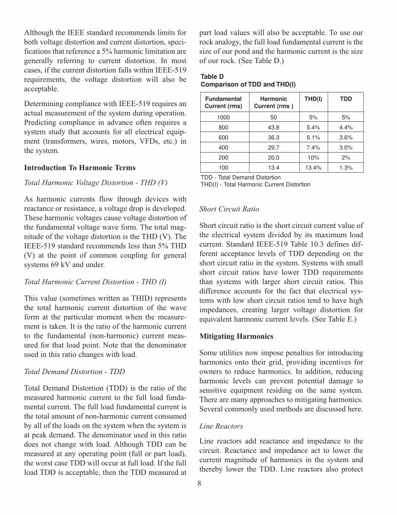
8
Although the IEEE standard recommends limits forboth voltage distortion and current distortion, speci-fications that reference a 5% harmonic limitation aregenerally referring to current distortion. In mostcases, if the current distortion falls within IEEE-519requirements, the voltage distortion will also beacceptable.
Determining compliance with IEEE-519 requires anactual measurement of the system during operation.Predicting compliance in advance often requires asystem study that accounts for all electrical equip-ment (transformers, wires, motors, VFDs, etc.) inthe system.
Introduction To Harmonic Terms
Total Harmonic Voltage Distortion - THD (V)
As harmonic currents flow through devices withreactance or resistance, a voltage drop is developed.These harmonic voltages cause voltage distortion ofthe fundamental voltage wave form. The total mag-nitude of the voltage distortion is the THD (V). TheIEEE-519 standard recommends less than 5% THD(V) at the point of common coupling for generalsystems 69 kV and under.
Total Harmonic Current Distortion - THD (I)
This value (sometimes written as THID) representsthe total harmonic current distortion of the waveform at the particular moment when the measure-ment is taken. It is the ratio of the harmonic currentto the fundamental (non-harmonic) current meas-ured for that load point. Note that the denominatorused in this ratio changes with load.
Total Demand Distortion - TDD
Total Demand Distortion (TDD) is the ratio of themeasured harmonic current to the full load funda-mental current. The full load fundamental current isthe total amount of non-harmonic current consumedby all of the loads on the system when the system isat peak demand. The denominator used in this ratiodoes not change with load. Although TDD can bemeasured at any operating point (full or part load),the worst case TDD will occur at full load. If the fullload TDD is acceptable, then the TDD measured at
part load values will also be acceptable. To use ourrock analogy, the full load fundamental current is thesize of our pond and the harmonic current is the sizeof our rock. (See Table D.)
Short Circuit Ratio
Short circuit ratio is the short circuit current value ofthe electrical system divided by its maximum loadcurrent. Standard IEEE-519 Table 10.3 defines dif-ferent acceptance levels of TDD depending on theshort circuit ratio in the system. Systems with smallshort circuit ratios have lower TDD requirementsthan systems with larger short circuit ratios. Thisdifference accounts for the fact that electrical sys-tems with low short circuit ratios tend to have highimpedances, creating larger voltage distortion forequivalent harmonic current levels. (See Table E.)
Mitigating Harmonics
Some utilities now impose penalties for introducingharmonics onto their grid, providing incentives forowners to reduce harmonics. In addition, reducingharmonic levels can prevent potential damage tosensitive equipment residing on the same system.There are many approaches to mitigating harmonics.Several commonly used methods are discussed here.
Line Reactors
Line reactors add reactance and impedance to thecircuit. Reactance and impedance act to lower thecurrent magnitude of harmonics in the system andthereby lower the TDD. Line reactors also protect
Fundamental Harmonic THD(I) TDDCurrent (rms) Current (rms )
1000 50 5% 5%
800 43.8 5.4% 4.4%
600 36.3 6.1% 3.6%
400 29.7 7.4% 3.0%
200 20.0 10% 2%
100 13.4 13.4% 1.3%
Table DComparison of TDD and THD(I)
TDD - Total Demand DistortionTHD(I) - Total Harmonic Current Distortion

9
devices from large current spikes with short risetimes. A line reactor placed between the VFD andthe motor would help protect the motor from currentspikes. A line reactor placed between the supply andVFD would help protect the supply from currentspikes. Line reactors are typically only usedbetween the VFD and the motor when a freestand-ing VFD is mounted more than fifty feet from themotor. This is done to protect the motor windingsfrom voltage peaks with extremely quick rise times.
Passive Filters
Trap Filters are devices that include an electrical cir-cuit consisting of inductors, reactors, and capacitorsdesigned to provide a low impedance path to groundat the targeted frequency. Since current will travelthrough the lowest impedance path, this prevents theharmonic current at the targeted frequency frompropagating through the system. Filters can bemounted inside the drive cabinet or as free standingdevices. Trap filters are typically quoted to meet aTHD(I) value that would result in compliance withIEEE-519 requirements if the system were other-wise already in compliance.
Active Filters
Some devices measure harmonic currents andquickly create opposite current harmonic waveforms. The two wave forms then cancel out, pre-venting harmonic currents from being observedupstream of the filter. These types of filters general-ly have excellent harmonic mitigation characteris-tics. Active filters may reduce generator sizerequirements.
VFDs Using Active Front End Technology (AFE)
Some VFDs are manufactured with IGBT rectifiers.The unique attributes of IGBTs allow the VFD toactively control the power input, thereby loweringharmonics, increasing power factor and making theVFD far more tolerant of supply side disturbances.The AFE VFDs have ultra low harmonics capable ofmeeting IEEE-519 standards without any externalfilters or line reactors. This significantly reducesinstallation cost and generator size requirements.An AFE drive provides the best way to take advan-tage of VFD benefits and minimize harmonics.
Multi-Pulse VFDs (Cancellation)
There are a minimum of six rectifiers for a three-phase AC VFD. There can be more, however.Manufacturers offer 12, 18, 24, and 30 pulse drives.A standard six-pulse drive has six rectifiers, a12-pulse drive has two sets of six rectifiers, an18-pulse drive has three sets of six rectifiers and soon. If the power connected to each set of rectifiers isphase shifted, then some of the harmonics producedby one set of rectifiers will be opposite in polarityfrom the harmonics produced by the other set of rec-tifiers. The two wave forms effectively cancel eachother out. In order to use phase shifting, a specialtransformer with multiple secondary windings mustbe used. For example, with a 12-pulse VFD, aDelta/Delta-Wye transformer with each of the sec-ondary phases shifted by 30 degrees would be used.
ISC/IL <11 11<7<17 17<h<23 23<h<35 35<h TDD
<20 4.0 2.0 1.5 0.6 0.3 5.0
20<50 7.0 3.5 2.5 1.0 0.5 8.0
50<100 10.0 4.5 4.0 1.5 0.7 12.0
100<1000 12.0 5.5 5.0 2.0 1.0 15.0
>1000 15.0 7.0 6.0 2.5 1.4 20.0
LEGEND: h = harmonic numberISC = maximum short-circuit current at PCC IL = maximum demand load current (fundamental) at PCC
Table ERepresentation of IEEE Table 10.3

NOTE: It is the responsibility of the user to evaluatethe accuracy, completeness or usefulness of anycontent in this paper. Neither Carrier nor its affiliatesmake any representations or warranties regardingthe content contained in this paper. Neither Carriernor its affiliates will be liable to any user or anyoneelse for any inaccuracy, error or omission, regardlessof cause, or for any damages resulting from any use,reliance or reference to the content in this paper.
10
REFERENCES
IEEE Standard 519-1992. “IEEE Recommended Practices and Requirements of Harmonic Control in Electrical Power Systems.”
Rockwell Automation. “Dealing with line harmonicsfrom PWM variable frequency drives.”
John F. Hibbard, Michael Z. Lowenstein. “Meeting IEEE 519-1992 Harmonic Limits Using Harmonic Guard Passive Filters” (TRANS-COIL, INC)
Tony Hoevenaars, P. Eng, Kurt LeDoux, P.E., Matt Colosina. 2003. “Interpreting IEEE Std 519 and Meeting its Harmonic Limits inVFD Applications.” (IEEE paper No. PCIC-2003-XX).
Gary Rockis, Glen Mazur, American TechnicalPublishers, Inc. 1997. “Electrical MotorControls.”
Richard H. Smith, P.E., Pure Power. 1999. “Power Quality Vista Looks Good Thanks to IGBTs.”
FURTHER READING FROM CARRIER
Carrier. 1993. Harmonics: A Brief Introduction.
Carrier. 1999. 19XRV Marketing Guide.
Carrier. 2005. Carrier Introduces Rotary Chillerswith Liquiflo2 Variable Speed Drive.
Carrier. 2005. Carrier Variable Speed Screw WhitePaper.
CONCLUSION
• VFDs provide the most energy efficient means of capacity control.
• VFDs have the lowest starting current of any starter type.
• VFDs reduce thermal and mechanical stresses on motors and belts.
• VFD installation is as simple as connecting the power supply to the VFD.
• VFDs with AFE technology can meet even the most stringent harmonic standards and reducebackup generator sizing.
• VFDs provide high power factor, eliminating the need for external power factor correction capacitors.
• VFDs provide lower KVA, helping alleviate voltage sags and power outages.
VARIABLE SPEEDSCREW COMPRESSOR
RAISING THE BAR FOR VARIABLE SPEED PERFORMANCE
Carrier CorporationSyracuse, New York
October 2005
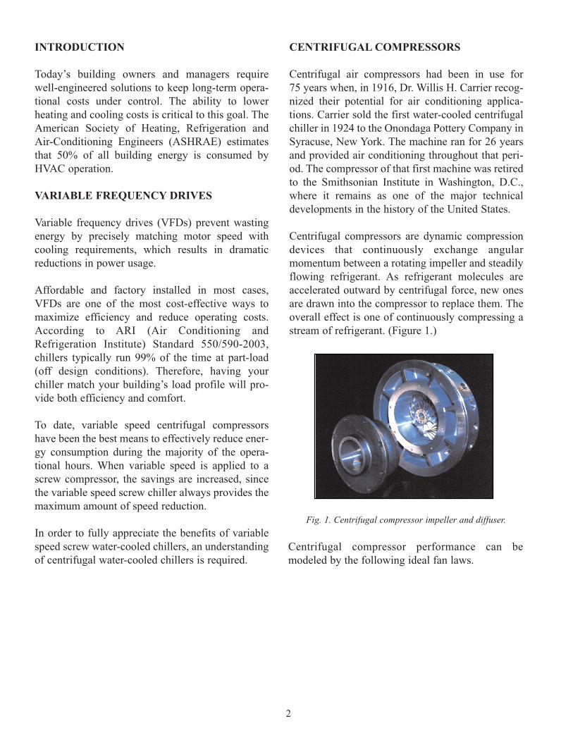
INTRODUCTION
Today’s building owners and managers requirewell-engineered solutions to keep long-term opera-tional costs under control. The ability to lowerheating and cooling costs is critical to this goal. TheAmerican Society of Heating, Refrigeration andAir-Conditioning Engineers (ASHRAE) estimatesthat 50% of all building energy is consumed byHVAC operation.
VARIABLE FREQUENCY DRIVES
Variable frequency drives (VFDs) prevent wastingenergy by precisely matching motor speed withcooling requirements, which results in dramaticreductions in power usage.
Affordable and factory installed in most cases,VFDs are one of the most cost-effective ways tomaximize efficiency and reduce operating costs.According to ARI (Air Conditioning andRefrigeration Institute) Standard 550/590-2003,chillers typically run 99% of the time at part-load(off design conditions). Therefore, having yourchiller match your building’s load profile will pro-vide both efficiency and comfort.
To date, variable speed centrifugal compressorshave been the best means to effectively reduce ener-gy consumption during the majority of the opera-tional hours. When variable speed is applied to ascrew compressor, the savings are increased, sincethe variable speed screw chiller always provides themaximum amount of speed reduction.
In order to fully appreciate the benefits of variablespeed screw water-cooled chillers, an understandingof centrifugal water-cooled chillers is required.
CENTRIFUGAL COMPRESSORS
Centrifugal air compressors had been in use for75 years when, in 1916, Dr. Willis H. Carrier recog-nized their potential for air conditioning applica-tions. Carrier sold the first water-cooled centrifugalchiller in 1924 to the Onondaga Pottery Company inSyracuse, New York. The machine ran for 26 yearsand provided air conditioning throughout that peri-od. The compressor of that first machine was retiredto the Smithsonian Institute in Washington, D.C.,where it remains as one of the major technicaldevelopments in the history of the United States.
Centrifugal compressors are dynamic compressiondevices that continuously exchange angularmomentum between a rotating impeller and steadilyflowing refrigerant. As refrigerant molecules areaccelerated outward by centrifugal force, new onesare drawn into the compressor to replace them. Theoverall effect is one of continuously compressing astream of refrigerant. (Figure 1.)
2
Fig. 1. Centrifugal compressor impeller and diffuser.
Centrifugal compressor performance can bemodeled by the following ideal fan laws.
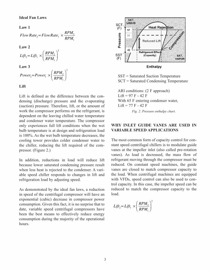
Ideal Fan Laws
Law 1
Law 2
Law 3
Lift
Lift is defined as the difference between the con-densing (discharge) pressure and the evaporating(suction) pressure. Therefore, lift, or the amount ofwork the compressor performs on the refrigerant, isdependent on the leaving chilled water temperatureand condenser water temperature. The compressoronly experiences full lift conditions when the wetbulb temperature is at design and refrigeration loadis 100%. As the wet bulb temperature decreases, thecooling tower provides colder condenser water tothe chiller, reducing the lift required of the com-pressor. (Figure 2.)
In addition, reductions in load will reduce liftbecause lower saturated condensing pressure resultwhen less heat is rejected to the condenser. A vari-able speed chiller responds to changes in lift andrefrigeration load by adjusting speed.
As demonstrated by the ideal fan laws, a reductionin speed of the centrifugal compressor will have anexponential (cubic) decrease in compressor powerconsumption. Given this fact, it is no surprise that todate, variable speed centrifugal compressors havebeen the best means to effectively reduce energyconsumption during the majority of the operationalhours.
SST = Saturated Suction TemperatureSCT = Saturated Condensing Temperature
ARI conditions: (2 F approach) Lift = 97 F - 42 FWith 65 F entering condenser water, Lift = 77 F - 42 F
WHY INLET GUIDE VANES ARE USED INVARIABLE SPEED APPLICATIONS
The most common form of capacity control for con-stant speed centrifugal chillers is to modulate guidevanes at the impeller inlet (also called pre-rotationvanes). As load is decreased, the mass flow ofrefrigerant moving through the compressor must bereduced. On constant speed machines, the guidevanes are closed to match compressor capacity tothe load. When centrifugal machines are equippedwith VFDs, speed control can also be used to con-trol capacity. In this case, the impeller speed can bereduced to match the compressor capacity to theload.
3
Fig. 2. Pressure enthalpy chart.
Lift LiftRPM
RPM2 12
1
2
∝ ×
Flow Rate FlowRateRPM
RPM2 12
1
∝ ×
Power PowerRPM
RPM2 12
1
3
∝ ×
Lift LiftRPM
RPM2 12
1
2
∝ ×

4
Recalling that the lift produced by a centrifugalcompressor is also reduced when speed is reduced,we can determine that speed adjustment alone can-not always be used to regulate the variable speedcentrifugal chiller. Under certain lift conditions, thespeed is reduced as much as lift requirements willallow and then guide vanes are used to complete theload reduction. Mechanical unloaders of any kindintroduce inefficiency. So while speed reduction isalmost always obtained with any reduction of lift orload requirements, the question becomes one ofmagnitude. The amount of capacity reduction per-formed by speed reduction, relative to the amountof capacity reduction performed by guide vanes isan indication of the centrifugal chillers ability tocapture all theoretical savings at a given operatingpoint. Conversely, the more the guide vanes areclosed, the higher the amount of inefficiency intro-duced into the system.
Given the cubic relationship of speed and powereven a small amount of speed reduction yields a sig-nificant reduction in energy. However, the morespeed reduction possible, the greater the energysavings.
UNDERSTANDING SCREW COMPRESSORS
Heinreich Krigar of Germany developed the firstscrew compressor in 1878. In the early 1930’s, aSwedish engineer by the name of Alf Lysholmdeveloped the profile of the modern screw compres-sor for gas and steam turbine applications. Screwcompressors have been used in HVAC applicationsfor nearly three decades. (Figure 3).
The screw compressor is classified a positive dis-placement compressor, which simply means that avolume of gas is trapped with an enclosed spacewhose volume is then reduced. Conventional rotaryscrew compressors are composed of two parallelrotors with external helical profiles fit into a casing.(Figure 3.) One of the rotors is coupled to the motor (drive rotor) and as it turns it moves the other rotor(driven rotor), similar to a common gear set. Thegeometric profile of the rotating rotors is difficult to
visualize. It is easier to relate the compressionprocess to a reciprocating compressor, if you con-sider the drive rotor as the piston and the drivenrotors as the cylinder. As the drive rotors and drivenrotors unmesh, an empty cylinder is created, draw-ing in suction gas through the synchronized openingon the rotor suction face. As rotation continues, thesuction and discharge rotor faces are sealed off,trapping the gas in the cylinder. When this happens,the meshing point moves toward the discharge endof the rotors and drives the gas ahead of it. The dis-charge port provided for the gas escape is relativelysmall, compared to the suction port, resulting in pos-itive displacement compression.
Rotary screw compressors are well known for theirrobustness, simplicity, and reliability. They aredesigned for long periods of continuous operation,needing very little maintenance. Screw compressorscan overcome high lift when speed is reduced,allowing energy savings without the possibility ofsurge as the compressor unloads.
VARIABLE SPEED SCREW COMPRESSORS
For positive displacement compressors, speed isindependent of lift, or worded another way, thecompressor can develop the same amount of lift atany speed. Therefore, mechanical loaders can bereplaced entirely by speed control. As discussedearlier, centrifugal compressors may require speedcontrol coupled with some closure of the inlet guidevanes. The variable speed screw compressor neverhas to temper speed control with a guide vane orslide valve, and therefore captures the maximum
Fig. 3. Conventional twin screw compressor.

5
energy reduction available at a given operatingcondition. Even small changes in speed createsignificant changes in energy consumption.Combine this incremental advantage with superiorcompression efficiencies, and a clear picture of theenergy savings potential of this technology emerges.
Variable speed drives used with screw compressorsare new to the HVAC industry, but they have beenused successfully in various air compression andrefrigeration applications. In these applications,screw compressors coupled with VFDs have beenutilized to ensure efficient compression at partialand full capacities. Variable speed screw compres-sors allow a wide range of capacity control whilemaximizing efficiency.
WHY COMPROMISE?
The variable speed screw chiller combines the bestfeatures of positive displacement screw chillers andvariable speed technology. The result is a superiorchiller with no compromises. A screw compressorwith a tri-rotor provides simplicity and reliability.(Figure 4.)
The direct-drive, tri-rotor design allows for shorterrotors and is about 5 to 10% more efficient than thetwin-rotor design. The tri-rotor also balances thrust,which reduces bearing loads.
Fig. 4. - Tri-rotor screw compressor.
A VFD CHILLER FOR HUMID CLIMATES
Applications where high lift requirements remaineven as cooling loads decrease may favor variablespeed screw chillers more significantly. An exampleof this application is a building located in a hot andhumid climate where cooling loads can vary whileoutdoor-air temperatures (dry bulb/wet bulb) remainhigh.
A variable speed screw compressor chiller is approx-imately 10 to 20% more efficient than all variablespeed centrifugal compressors with constant 85 Fentering condenser water.
CHILLER SELECTION CRITERIA
System part load performance is a crucial factor inchiller selection, since chillers rarely operate at fullload design conditions. Consulting engineers andowners should understand the importance of usingsystem part load performance for their specificapplication as the selection criterion. Simply, theunit with the lowest system part load performancewill provide the greatest energy savings across itsentire operational range. The system part load,when multiplied by total annual ton-hours of cool-ing, provides an estimate of the total annual kilo-watt-hour consumption. A variable speed screwcompressor chiller saves energy in all operatingconditions.

6
NOTE: It is the responsibility of the user to evaluatethe accuracy, completeness or usefulness of any con-tent in this paper. Neither Carrier nor its affiliatesmake any representations or warranties regardingthe content contained in this paper. Neither Carriernor its affiliates will be liable to any user or anyoneelse for any inaccuracy, error or omission, regardlessof cause, or for any damages resulting from any use,reliance or reference to the content in this paper.
REFERENCE
Reindl, Douglas T. and Todd B. Jekel. “Screw Compressors: Selection Considerations for Efficient Operation.” Paper presented at the 21st IIR (International Institute of Refrigeration) International Congress of Refrigeration, Washington, D.C., 17-22 August 2003.