appendix 6 husky engineering specifications
TRANSCRIPT

Husky Oil Operations Limited June 2006 Esther Court Pipeline
Appendix 6
Husky Engineering Specifications

ENGINEERING SPECIFICATIONS
WELDING
PS-MW-01
Rev Date Description AuthorChecked
By
Approval
Technical
Approval
Management
0 2002/11/8 Issued for use. AB JL
ENGINEERING SPECIFICATIONSWELDING
PS-MW-01Issue: 2002/11/8
Rev. 0
H:\HUSKY SPECS FINALIZED VERSION\PS-MW-01.DOC Page 1 of 13
Comments on this Specification from all users are encouraged. Please send comments and suggestions to
1.0 Scope
1.1 This Specification shall apply to the general welding requirements used for; fabrication, assembly,alteration and repair of carbon steel and stainless steel pressure vessels, pressure and industrial piping,structural steel, storage tanks and gathering/transmission pipelines.
2.0 Reference Documents
2.1 Welding shall be in accordance with the latest editions of the following regulations, codes, standardsand specifications. In all cases where more than one code, standard or specification applies to the samecondition, the most stringent one shall apply. Conflicts among any of the provisions of these listedcodes, standards or specifications shall be referred to Husky for resolution.
American Society of Mechanical Engineers (ASME)
Section IPower Boilers
Section IIMaterial Specifications
Section VIII, Division 1Unfired Pressure Vessels
Section IXWelding and Brazing Qualifications
B31.3Chemical Plant and Petroleum Refinery Piping
B31.1Power Piping
American Petroleum Institute (API)
Standard 620Recommended Rules for Design and Construction of Large Welded, Low Pressure Storage Tanks
Standard 650Welded Steel Tanks for Oil Storage
Standard 12FShop Fabricated Storage Tanks
American Welding Society (AWS)
WWBWelding Handbook
D10.12Recommended Practices and Procedures for Welding Plain Carbon Steel Pipe
D10.4Recommended Practices for Welding Austenitic Chromium-Nickel Stainless Steel Piping and Tubing

ENGINEERING SPECIFICATIONSWELDING
PS-MW-01Issue: 2002/11/8
Rev. 0
H:\HUSKY SPECS FINALIZED VERSION\PS-MW-01.DOC Page 2 of 13
Canadian Standards Association (CSA)
CSA B51Code for the Construction and Inspection of Boilers and Pressure Equipment
CSA W47.1Certification of Companies for Fusion Welding of Steel Structures
CSA W59Welded Steel Construction
CSA Z662Oil & Gas Pipeline Systems
National Association of Corrosion Engineers (NACE)
MR-01-75Sulphide Stress Cracking Resident Metallic Metals for Oil Field Equipment
RP-01-78Fabrication Details, Surface Finish Requirements, and Proper Design Considerations for Tanks andVessels to be Lined for Immersion Service
2.2 Equipment design, fabrication and examination shall meet the requirements of the Codes of Design andFabrication stated in the applicable Husky specifications and the regulations for the Province ofinstallation.
3.0 General
3.1 Welding Processes
3.1.1 Welding is to be performed manually, semi-automatically and/or automatically using SMAW, GTAW,SAW, GMAW or FCAW processes. All welding procedure specifications and associated procedurequalification records to be submitted to Husky for acceptance prior to commencement of any welding.
3.1.2 Use of FCAW welding process is permitted for carbon steel shop fabrication of:
• ASME Section VIII Division 1 pressure equipment (see sections 4 & 5 for limitations)
• ASME B31.3 pressure piping
• Storage Tanks
• Structural Steel
3.1.2.1 All FCAW welding shall be performed using:
• E7XT-1MJ-H8R or E7XT-5MJ-H8R electrode wire
• Inverter type power source
3.1.2.2 Maximum weld metal tensile strength shall not exceed 552 MPa (80 ksi)
3.1.3 Gas metal arc welding is restricted to the short circuit transfer method (18 V to 25 V) only with amaximum total deposited metal thickness of 9 mm.
3.1.4 Unless otherwise accepted by Husky Engineering shielded metal arc welding of carbon steel shall beperformed using cellulose sodium coated electrode (EXX10) for the root and low hydrogen potassium,iron powder coated electrode (EXX18) for the fill & cap.
ENGINEERING SPECIFICATIONSWELDING
PS-MW-01Issue: 2002/11/8
Rev. 0
H:\HUSKY SPECS FINALIZED VERSION\PS-MW-01.DOC Page 3 of 13
3.1.5 Shielded metal arc welding of carbon steel gathering/transmission pipelines may be performed usingcellulose sodium coated electrode (EXX10) for the root, fill & cap.
3.2 Welding Procedure Specifications
3.2.1 Welding procedure specifications shall be developed and formatted in accordance with the applicableCode of Fabrication. In addition to the required essential and supplemental essential elements theprocedures shall also address the following requirements.
• Microhardness qualification for welds subject to post weld heat treatment
• Minimum preheat of 10ºC
• Maximum weave of 3 times the electrode diameter for carbon steel
• Maximum weave of 2-1/2 times the electrode diameter for stainless steels
• Maximum interpass temperature of 177ºC for stainless steel
• Use of backing rings is not acceptable.
• Maximum thickness of unbeveled joints shall be 3 mm for single side welded and 6 mm for doubleside welded joints
3.2.2 Welding procedure specification and procedure qualification records shall be submitted to Husky, atthe bid stage, for review and acceptance.
3.3 Welding Procedure Qualification Records
3.3.1 Weld procedure specifications shall be qualified for mechanical properties in accordance with theapplicable Code of Fabrication.
3.3.2 Weld procedure specifications requiring post weld heat treatment shall be:
• Qualified with heat treatment representative of the production welding.
• Qualified for microhardness at 1 mm below each surface and mid thickness for weld metal, heataffected adjacent base metal.
3.3.3 Low temperature toughness tests shall be qualified at -45ºC unless otherwise specified in the jobspecification.
3.4 Design
3.4.1 Vendor shall prepare fully detailed drawings showing welded connections, weld symbols in accordancewith AWS STD. A 2.4 and joint preparations including tolerances. Reference to all applicable weldingprocedure specification numbers shall be made for each weld.
3.4.2 All weld joints shall be designed for full penetration, unless otherwise accepted by Husky.
3.4.3 All welded joints, which are to coated or lined for immersion service, shall be designed and finished inaccordance with NACE RP-01-78.
3.4.4 Seal welding of threaded connections is not allowed.

ENGINEERING SPECIFICATIONSWELDING
PS-MW-01Issue: 2002/11/8
Rev. 0
H:\HUSKY SPECS FINALIZED VERSION\PS-MW-01.DOC Page 4 of 13
3.5 Materials
3.5.1 Material classification shall be as defined in the applicable Code of Design/Fabrication
ASME Boiler, Pressure Vessel & Piping − ASME Section IX. - P number and Group number
CSA Pipeline − CSA Standard Z245
API Storage Tanks − API 620, 650, 12D and/or 12F
Structural Steel − CSA Standard S16.1
3.5.2 Vendor shall ensure that all materials are identified and documented prior to welding.
3.6 Welding Consumables
3.6.1 Welding consumables shall be specified in the welding procedure specification.
3.6.2 All welding consumables shall conform to ASME Section II, Part C and be clearly marked with theappropriate AWS classification number.
3.6.3 Consumables shall be maintained in accordance with manufacturer recommendations. Low hydrogenelectrodes shall be maintained in a heated oven until time of use. Low hydrogen electrodes exposed tothe atmosphere for longer than 1 hour shall be reconditioned to Manufacturer specifications ordiscarded.
3.7 Heat Treatment
3.7.1 Prior to work commencing, the Vendor shall submit to Husky a detailed heat treatment procedure incompliance with the applicable welding procedure specification(s) to be used.
3.7.2 All flange, machined and threaded surfaces shall be protected from oxidation during heat treatment.
3.7.3 All heat treatments are to be recorded on calibrated time/temperature charts traceable to the equipmentand signed by the heat treatment technician.
3.7.4 Welding or heating of new equipment after heat treatment is strictly prohibited.
3.8 Fabrication
3.8.1 Whenever possible, welding shall be performed in the flat position.
3.8.2 Temporary attachment and tack welds shall be performed by fully qualified welders using approvedwelding procedure specifications. Preheat requirements shall apply. All temporary welds and arc strikesshall be completely removed by grinding (removal by hammer blows is not permitted). Ground areashall be magnetic particle examined to ensure area is free of defects.
3.8.3 All welds shall be identified to the individual welder(s) by means of weather proof, lowchloride/halide, permanent marking adjacent to the weld. Welds shall be marked immediatelyfollowing completion. Welder's identity shall be documented on the NDE examination report and aNDE map. Unidentified welds are deemed unacceptable and subject to immediate cut-out.
ENGINEERING SPECIFICATIONSWELDING
PS-MW-01Issue: 2002/11/8
Rev. 0
H:\HUSKY SPECS FINALIZED VERSION\PS-MW-01.DOC Page 5 of 13
3.9 Weld Acceptability And Repair
3.9.1 All nondestructive examinations shall be performed and interpreted by personnel certified inaccordance with CGSB Level II or III. Husky is responsible for final weld acceptance and may rejectany weld regardless of NDE interpretation results.
3.9.2 First two production welds of each welder for pressure & transmission/gathering piping shall be 100%radiographed.
3.9.3 Magnetic particle examination shall be performed using the wet visible technique for sweet service andthe wet fluorescent technique for sour service.
3.9.4 All identified rejectable defects shall be completely removed by grinding or gouging. Repairs notrequiring complete wall thickness removal shall be visually , magnetic particle or liquid penetrantexamined to verify removal of identified defect prior to rewelding. Excavation area shall be minimum50 mm in length.
3.9.5 Repair welds shall be performed using original weld procedure specification or alternate acceptable toHusky.
3.9.6 Welds shall be re-examined by the same NDE examination technique used to detect the original defector alternative means acceptable to Husky. External surface defects may be removed by grinding andaccepted on visual examination providing weld metal removal and addition does not exceed originalweld cover pass thickness. Visual acceptance of weld repairs shall be recorded on theNDE examination report.
3.9.7 For each pressure piping & transmission/gathering piping defective weld identified for repair, twoadditional welds shall be examined as per ASME B31.3 Para 341.3.4 and appropriately identified as“tracers” on the examination report. Examination of additional welds shall be at the discretion of theHusky Engineer or Inspector.
3.10 In-Service Repairs & Alterations
3.10.1 Vendor's performing repairs and alterations shall maintain a quality program meeting the intent ofCSA Standard Q9002 acceptable to Husky. Repairs and alterations to pressure piping and equipmentshall be performed by qualified contractors holding a valid certificate of authorization from thejurisdictional authority.
3.10.2 All “General” and specific requirements of this Specification shall apply to in-service repair andalterations.
3.10.3 In service equipment and piping in sour service requiring repairs to product wetted surfaces orreplacement of product wetted components shall be subject to an initial hydrogen bake-out, inaccordance with Husky Procedure JSP-10, prior to commencement of any repair/alteration welding.
3.10.4 Post weld heat treatment of repaired or altered equipment and piping shall be performed in accordancewith the original design and code requirements.

ENGINEERING SPECIFICATIONSWELDING
PS-MW-01Issue: 2002/11/8
Rev. 0
H:\HUSKY SPECS FINALIZED VERSION\PS-MW-01.DOC Page 6 of 13
4.0 ASME Pressure Vessel, Boiler and Piping – Sweet Service
4.1 Application
4.1.1 This section specifies sweet service application requirements, in addition to Section 3, for thefabrication, repair and alteration of ASME pressure vessel, boiler and piping.
4.1.2 Design, weld procedure specification development and qualification, fabrication and examination shallconform to the applicable ASME Code of Fabrication, ASME Section IX and local jurisdictionalregulatory requirements.
4.2 Design
4.2.1 Minimum spacing of piping girth welds shall be the lesser of 150 mm or 2 times the nominal pipediameter.
4.2.2 Minimum spacing of pressure equipment weld seams shall be as specified in PS-VT-01 PressureVessels Section 5.3
4.3 Welder Performance Qualification
4.3.1 All welders shall be qualified in accordance with ASME Section IX. Record of qualification
4.3.2 Form QW 484 shall be completed for each welder and available to Husky for review.
4.3.3 Job specific welder qualification is not required unless specified.
4.4 Fabrication
4.4.1 All welding shall be performed using uphand progression.
4.4.2 All carbon steel piping and pressure containing equipment subject to amine service shall be post weldheat treated.
4.4.3 Root pass penetration of piping 60.3 mm (NPS 2) and less shall not exceed 1.6 mm. Use of gastungsten arc or gas metal arc welding process is preferable.
4.4.4 Use of FCAW process on compressor pulsation bottle category “D” welds is not allowed.
4.5 Weld Acceptability and Repair
4.5.1 Welds shall be examined in accordance with the requirements of the applicable ASME Code ofFabrication. All examinations shall be documented, traceable to the specific job and signed by thetechnician.

ENGINEERING SPECIFICATIONSWELDING
PS-MW-01Issue: 2002/11/8
Rev. 0
H:\HUSKY SPECS FINALIZED VERSION\PS-MW-01.DOC Page 7 of 13
4.5.2 Extent of NDE examination and acceptance criteria shall be as follows unless otherwise specified in thejob or equipment specific specification.
Application Extent & Type of Examination Acceptance Criteria
RT/UT * (butt) MT/PT (fillet)
ASME Sect I Per Code Same % as RT Per Code
ASME Sect VIII Div 1 Per Code Same % as RT Per Code
ASME B31.1 Per Code Same % as RT Per Code
ASME B31.3 (Sweet) 150-900# 10% butt welds10% fillet
weldsPer Code (Normal Service)
ASME B31.3 (Sweet) 1500-2500#100% butt
welds100% fillet
weldsPer Code (Cyclic Service)
* Ultrasonic examination shall be substituted for radiography where weld interpretation is not possible
4.5.3 Phased arrayed ultrasonic examination in accordance with ASME Code Case 2235-3 may be used as analternative to radiographic examination for weldments exceeding 168.3 mm in diameter (NPS 6) and12.7 mm (1/2 in) in wall thickness.
4.5.4 Pressure equipment category “D” welds completed using the FCAW process shall be 100%ultrasonically examined at a frequency of:
• one joint of each nozzle dimensional size
• one joint per each welder
• one joint per each weld procedure
4.5.5 All post weld heat treated carbon steel welds shall, upon completion, be subject to microhardnesstesting of the base metal, weld metal and the associated heat-affected-zones (HAZ). Hardness shall notexceed the 210 HV1
4.5.5.1 Pressure piping welds shall be examined at minimum 10% of furnace heat treated and 100% of localheat treated welds.
4.5.5.2 Pressure equipment shall be examined at a frequency of one test on each circumferential weld, one teston each longitudinal weld and one test each on 10% of nozzle category D & category C welds.
5.0 ASME Pressure Vessel, Boiler and Piping - Sour Service
5.1 Application
5.1.1 This section specifies requirements, in addition to sections 3 & 4, specific to Region 1 Transition Sourand Region 2 Sour service applications for the fabrication, repair and alteration of ASME pressurevessel, boiler and piping. Refer to Husky Specification PS-MW-03 Requirements for Sour Service, forfurther details.
5.2 Welding Procedure Specifications
5.2.1 Welding Procedure Specifications shall also address the following requirements.

ENGINEERING SPECIFICATIONSWELDING
PS-MW-01Issue: 2002/11/8
Rev. 0
H:\HUSKY SPECS FINALIZED VERSION\PS-MW-01.DOC Page 8 of 13
• Post weld heat treatment for all carbon steel pressure equipment welds
• Post weld heat treatment for all carbon steel pressure piping welds with wall thickness exceeding12.7 mm.
• Microhardness qualification. Maximum hardness for carbon steel shall be 210 HV1
5.3 Welding Procedure Qualification Records
5.3.1 Weld Procedure Specifications to be used in sour service, regardless of wall thickness, shall bequalified for microhardness at 1 mm below each surface and mid thickness for weld metal, heataffected zone and adjacent base metal. Maximum hardness for carbon steel shall be 210 HV1
5.4 Fabrication
5.4.1 All carbon steel pressure containing equipment subject to sour service shall be heat treated.
5.4.2 All carbon steel piping subject to Region 1 and 2 transition sour & sour service shall be heat treatedwhen the wall thickness exceeds 12.7 mm. In addition, when specified in the job, all welded carbonsteel piping exposed to higher levels sour service where H2S partial pressure exceeds 350 kPa (50 psi)and the pH is less than 4.5 shall be heat treated. Weld procedure specifications, regardless of wallthickness, shall be qualified for microhardness per section 5.3.1 of this specification.
5.5 Weld Acceptability And Repair
5.5.1 Extent of NDE examination and acceptance criteria shall be as follows unless otherwise specified in thejob or equipment specific specification.
ApplicationExtent & Type of
ExaminationAcceptance Criteria
RT/UT (Note 1) MT/PT
ASME Sect VIII Div 1(Reference Specification PS-MW-03)
100% buttwelds
100% filletwelds
Per Code plus zero internal/externalundercut, incomplete penetrationand burn through
ASME B31.3(Reference Specification PS-MW-03)
100% buttwelds
100% filletwelds
Per Code (Cyclic Service)
Note 1: Ultrasonic examination shall be substituted for Radiography where weld interpretation is notpossible
5.5.2 All post weld heat treated carbon steel welds shall, upon completion, be subject to microhardnesstesting of the base metal, weld metal and the associated heat-affected-zones (HAZ). Hardness shall notexceed the 210 HV1
5.5.2.1 Pressure piping welds shall be examined at minimum 10% of furnace heat treated and 100% of localheat treated welds.
5.5.2.2 Pressure equipment shall be examined at a frequency of one test on each circumferential weld, one teston each longitudinal weld and one test each on 10% of nozzle category D & category C welds.

ENGINEERING SPECIFICATIONSWELDING
PS-MW-01Issue: 2002/11/8
Rev. 0
H:\HUSKY SPECS FINALIZED VERSION\PS-MW-01.DOC Page 9 of 13
6.0 CSA Pipeline - Sweet Service
6.1 Application
6.1.1 This section specifies sweet service application requirements, in addition to section 3, for thefabrication, repair and alteration of CSA Standard Z662 gathering and transmission pipelines.
6.1.2 Design, weld procedure specification development and qualification, fabrication and examination shallconform to CSA Standard Z662 and local jurisdictional regulatory requirements.
6.2 Design
6.2.1 Minimum spacing of piping girth welds shall be the lesser of 150 mm or 2 times the nominal pipediameter.
6.3 Welding Procedure Specifications
6.3.1 Welding Procedure Specifications for above ground ASTM materials, as a minimum, shall meetrequirements of ASME Sections IX, B31.3 and section 4 of this Specification.
6.3.2 Welding Procedure Specification and Procedure Qualification Records shall be submitted to Husky, atthe bid stage, for review and acceptance.
6.4 Welding Procedure Qualification Records
6.4.1 Welding Procedure Specifications shall be qualified in accordance with the requirements ofCSA Standard Z662. All essential and non-essential elements shall be addressed for the applicableweld process to be used. Weld procedures for category II and category III materials shall be qualifiedfor impact toughness at project specified temperatures.
6.5 Welder Performance Qualification
6.5.1 All welders shall be qualified in accordance with CSA Standard Z662. Record of qualification(Husky Form JSP-RP-001or equivalent) shall be completed for each welder and available to Husky forreview. Acceptance criteria shall be same as specified job production welds.
6.5.2 Job specific welder qualification is required unless the welder has been qualified for a previous Huskyjob in the previous 3 months meeting the same material range, same diameter and thickness range andsame weld procedure essential variables.
6.6 Fabrication
6.6.1 All pipeline fabrication shall comply with the requirements of CSA Standard Z662 and the job specificspecification.
6.6.2 Welding may be performed in the downwind or upland progression dependent upon weld procedureand welder qualification.
6.6.3 All AST carbon steel materials shall be heat treated when the wall thickness exceeds 19 mm.

ENGINEERING SPECIFICATIONSWELDING
PS-MW-01Issue: 2002/11/8
Rev. 0
H:\HUSKY SPECS FINALIZED VERSION\PS-MW-01.DOC Page 10 of 13
6.6.4 Root pass penetration of piping 60.3 mm (NPS 2) and less shall not exceed 1.6 mm. Use of gastungsten arc or gas metal arc welding process is preferable.
6.7 Weld Acceptability And Repair
6.7.1 Welds shall be examined in accordance with the requirements of CSA Standard Z662. Extent of NDEexamination and acceptance criteria shall conform to CSA Standard Z662 Clause 7 requirements and asspecified in the job specific specification. Weld examination shall be performed minimum 60 minutesafter weld completion. Visual examination shall be performed and documented in accordance withCSA Standard Z662 Clause 7.2.12.9.3
6.7.2 Weld repairs shall be radiographically re-examined. Visible cover pass defects (porosity) may beremoved to depth of cover pass and rewelded with visual re-examination. Visual acceptance of surfaceweld repairs shall be documented on the NDE examination report.
6.7.3 Weld repairs exceeding half the wall thickness and 25% of the weld circumference shall requireminimum lapse time of 60 minutes between completion of weld and NDE examination.
7.0 CSA Pipeline - Sour Service
7.1 Application
7.1.1 This section specifies requirements, in addition to Section 3 & 6, specific to Region 1 Transition Sourand Region 2 Sour service applications for the fabrication, repair and alteration of CSA Standard Z662gathering and transmission pipelines. Refer to Husky Specification PS-MW-03 Requirements for SourService, for further details.
7.2 Welding Procedure Specifications
7.2.1 Welding Procedure Specifications shall also address the following requirements.
• Microhardness qualification
• Minimum preheat of 93ºC
7.3 Welding Procedure Qualification Records
7.3.1 Welding procedure specifications for sour service applications shall also be qualified to the followingrequirements:
• Mechanical Tests: Tensile tests shall be performed regardless of diameter or wall thickness
• Microhardness Tests:
16 readings each @ 1 mm from inner & 1 mm from outer surface base(4 total) HAZ (8 total), Weld (20 total) Max HV1 235 Samples to be taken@ 90º & 180º(surplus of mechanical test coupon)
• Preheat: 93ºC
• Postheat: Wrap and allow to slow cool when ambient temperature is less than 10ºC
7.4 Welder Performance Qualification
7.4.1 All welders qualification tests shall include radiographic examination, mechanical, internal & externalvisual and microhardness examination. Microhardness testing shall consists of a 5 point traverse @6 & 12 o'clock position of test coupon. Acceptance criteria Max HV1 235.
ENGINEERING SPECIFICATIONSWELDING
PS-MW-01Issue: 2002/11/8
Rev. 0
H:\HUSKY SPECS FINALIZED VERSION\PS-MW-01.DOC Page 11 of 13
7.5 Fabrication
7.5.1 All ASTM carbon steel materials shall be post weld heat treated when the wall thickness exceeds12.7 mm. as required by section 5.4.2.
7.6 Weld Acceptability and Repair
7.6.1 Welds in sour service shall meet the following additional acceptance criteria:
• No lack of cross penetration
• No undercutting
• No burn through
• No non-fusion
• No surface porosity
7.6.2 Any single weld rejectable defect or accumulation of weld rejectable defects that exceeds 50% of thejoint circumference shall be cut out and the entire weld replaced.
7.6.3 Maximum length of any single root bead rejectable defect shall be 150 mm; defects shall be separatedby a minimum of 150 mm. Welds exceeding this criteria shall be cut out.
7.6.4 Maximum length of any single fill & cap rejectable defect shall be 200 mm; defects shall be separatedby a minimum of 200 mm. Welds exceeding this criteria shall be cut out.
7.6.5 Regardless of limits established above, accumulation of imperfections shall not exceed limits asspecified in CSA Standard Z662, clause 7.2.9.9.1
7.6.6 One repair attempt only shall be allowed for through wall (root & hot pass) defect repairs. Two repairattempts only shall be allowed for mid wall (fill & cap) defect repairs. If the weld repair is notsatisfactory, the entire weld shall be cut out and replaced.
7.6.7 Weld repairs shall be radiographically re-examined. Visible cover pass defects (porosity) may beremoved to depth of cover pass and rewelded with visual re-examination. Visual acceptance of surfaceweld repairs shall be documented on the NDE report.
7.6.8 Weld repairs exceeding half the wall thickness and 25% of the weld circumference shall requireminimum lapse time of 60 minutes between completion of weld and NDE examination.
8.0 Storage Tanks
8.1 Application
8.1.1 This section specifies sweet and sour service application requirements, in addition to section 3, for thefabrication, repair and alteration of API and ULC steel storage tanks.
8.2 Design
8.2.1 Weld joint design shall conform to the applicable API, ULC or CSA standard of fabrication
8.2.2 Partial penetration butt welds are not acceptable.

ENGINEERING SPECIFICATIONSWELDING
PS-MW-01Issue: 2002/11/8
Rev. 0
H:\HUSKY SPECS FINALIZED VERSION\PS-MW-01.DOC Page 12 of 13
8.2.3 Minimum spacing of weld joints shall be in accordance with API 650.
8.3 Welding Procedure Specifications
8.3.1 Welding procedure specifications shall be developed in accordance with the requirements ofASME Section IX. All essential and non-essential elements shall be addressed for the applicable weldprocess to be used.
8.4 Welding Procedure Qualification Records
8.4.1 Welding procedure specifications shall be qualified in accordance with the requirements ofASME Section IX and the applicable standard of fabrication. All essential and non-essential elementsshall be addressed for the applicable weld process to be used.
8.4.2 Low temperature toughness tests shall be qualified at -45 ºC unless otherwise specified.
8.5 Welder Performance Qualification
8.5.1 All welders shall be qualified in accordance with ASME Section IX. Record of Qualification(Form QW 484) shall be completed for each welder and available to Husky for review.
8.5.2 Job specific welder qualification is not required unless specified.
8.6 Fabrication
8.6.1 All welding shall be performed using uphand progression with exception of double side welded jointsin which downhand progression is acceptable.
8.7 Weld Acceptability and Repair
8.7.1 Welds shall be examined in accordance with the requirements of the applicable standard of fabricationand ASME Section V. Extent of NDE examination and acceptance criteria shall be as specified in theJob or Equipment specific Specification. All examinations shall be documented, traceable to thespecific job and signed by the technician.
8.7.2 Vertical tank shell to floor interior weld shall be liquid penetrant examined prior to performance ofshell to floor exterior weld
9.0 Structural Steel
9.1 Application
9.1.1 This section specifies requirements, in addition to Section 3, for the fabrication, repair and alteration ofstatic and dynamic loaded structural steel.
9.2 Design
9.2.1 Weld joint design shall conform to the CSA Standard S16.1 and standard designs of CSA W59/AWSD10.12
9.2.2 Partial penetration butt welds are not acceptable.
ENGINEERING SPECIFICATIONSWELDING
PS-MW-01Issue: 2002/11/8
Rev. 0
H:\HUSKY SPECS FINALIZED VERSION\PS-MW-01.DOC Page 13 of 13
9.2.3 Minimum spacing of weld joints shall be in 150 mm.
9.3 Welding Procedure Specifications
9.3.1 Welding Procedure Specifications shall be developed in accordance with the requirements ofCSA Standard W59 or ASME Section IX. All essential and non-essential elements shall be addressedfor the applicable weld process to be used.
9.4 Welding Procedure Qualification Records
9.4.1 Welding Procedure Specifications shall be qualified in accordance with the requirements ofCSA Standard W59 or ASME Section IX and the applicable Standard of Fabrication. All essential andnon-essential elements shall be addressed for the applicable weld process to be used.
9.5 Welder Performance Qualification
9.5.1 All welders shall be qualified in accordance with CSA Standard W59 or ASME Section IX. Record ofqualification shall be completed for each welder and available to Husky for review.
9.5.2 Job specific welder qualification is not required unless specified.
9.6 Fabrication
9.6.1 All welding shall be performed using uphand progression.
9.6.2 Partial penetration welds are not acceptable
9.7 Weld Acceptability And Repair
9.7.1 Welds shall be examined in accordance with the requirements of the applicable Standard of Fabricationand ASME Section V. Extent of NDE examination and acceptance criteria shall be as specified in theJob or Equipment specific Specification. All examinations shall be documented, traceable to thespecific job and signed by the technician.
9.7.2 Beam splice butt welds shall be 100% radiographic examined.
9.7.3 Dynamically loaded fillet welds shall be 10% magnetic particle or liquid penetrant examined.

ENGINEERING SPECIFICATIONS
HUSKY SPECIFICATION MANAGEMENT SYSTEM
DS-GS-01
Rev Date Description AuthorChecked
By
Approval
Technical
Approval
Management
1 2003/03/11 Issued for use. JL MP/SEP
2 2003/04/30 Issued for use SEP
3 2005/05/18 Issued for use – added website info SEP SEP

ENGINEERING SPECIFICATIONSHUSKY SPECIFICATION MANAGEMENT SYSTEM
DS-GS-01Issue: 2005/05/18
Rev. 3
DS-GS-01 Rev 3.doc Page 1 of 15
Comments on this Specification from all users are encouraged. Please send comments and suggestions to [email protected] .
1.0 Purpose, Objectives and Scope
1.1 The purpose of this document is to provide the minimum requirements for the use, management and
change to the Husky Specifications which have a scope as outlined in Section 1.3 of this Specification.
1.2 The objectives of Husky Specifications are:
• To provide up-to-date, uniform and consistent standards and specifications that can be applied on a broad basis to new facility design, procurement and construction, and to support ongoing facility
design activities.
• To document approved practices and standards that:
− Meet or exceed applicable regulatory requirements
− Embody good engineering practice
− Capture Husky construction/operating/maintenance experience and current safety/ environmental requirements
• To support projects in balancing life-cycle costs, schedule and quality/safety/risk requirements
• Enable quality assurance (QA) and inspection systems to have a set specification basis for
establishing compliance and acceptable quality
1.3 The scope of Husky Specifications is to:
• Supercede the “Production Division Standard Specifications”
• Have broad application to oil and gas processing and pipeline facilities but does not include:
− Lloydminster Upgrader (which is using its own specs)
− East Coast/International
− Retail marketing facilities
• Provide standards/specifications that are commonly needed but not those that are readily covered by existing industry standards. Project-specific specifications should be developed to satisfy needs
beyond these.
1.4 Husky Specifications are intended for use on Husky facilities only. They may be applied to
“grass roots” facilities or to additions to existing facilities. If a Management of Change review supports
using the specification that the facility was originally designed on, then a deviation request shoulddocument this.
1.5 Husky Specifications reside within a management system as shown in Appendix B and as further
described in the following sections.
2.0 Reference Documents
• Husky Specifications “Specification List.” These Specifications have been considered the current
priority for development and issue.
ENGINEERING SPECIFICATIONSHUSKY SPECIFICATION MANAGEMENT SYSTEM
DS-GS-01Issue: 2005/05/18
Rev. 3
DS-GS-01 Rev 3.doc Page 2 of 15
3.0 Specification System Structure and Grouping
3.1 General Structure
The Husky Specifications are grouped as follows:
• Specification types: e.g., Design, Procurement and Construction - see Section 3.2 of this Specification
• Specification disciplines: e.g., General, Mechanical, Electrical, etc. - see Section 3.3 of this Specification
3.2 Specification Types
3.2.1 Design Specifications (DS): These specifications set out Husky requirements to internal Husky users,
engineering/procurement contractors, packaged equipment fabricators who design the packages, suppliers and to others who need design guidelines.
3.2.2 Procurement Specifications (PS): These Specifications define the basic details of materials and equipment to be procured. They are normally used with requisitions for bid documents and purchase
orders for materials and equipment. These Specifications are normally supplemented with data sheets,
or a job-specific specification for the equipment. In addition to these specifications, the requisition also includes a scope of supply listing, a governing list of reference documents (which lists these
specifications and others as applicable), documentation and data requirements, inspection and test
requirements, and packing and shipping instructions.
3.2.3 Construction Specifications (CS): These Specifications specify methods, requirements and materials
for shop fabrication and field construction. They are generally included in construction bid request and contract packages. In addition to these Specifications, the bid request or contract package will include
full details on work and supply scope, construction drawings, documentation, and data requirement and
other requirements.
3.3 Specification Disciplines
The specifications are grouped by discipline as shown in Table 3.1, Specification Disciplines of this Specification.
Table 3.1, Specification Disciplines
Abbreviation Description
GS General
CS Civil and Fire Protection
PF Piping for Facilities
PL Pipeline
MW Material, Welding, Corrosion & Insulation
VT Pressure Vessel and Tanks
HT Heat Transfer
RE Rotating Equipment
EL Electrical
IC Instrumentation and Controls
DG Drafting Guidelines

ENGINEERING SPECIFICATIONSHUSKY SPECIFICATION MANAGEMENT SYSTEM
DS-GS-01Issue: 2005/05/18
Rev. 3
DS-GS-01 Rev 3.doc Page 3 of 15
3.4 Specification Numbering System, e.g., DS-PL-01
DS - PL - 01
Specification Number (odd numbering starting at 01)
Specification Discipline (see table 3.1 of this specification)
Specification Type
4.0 Responsibilities
4.1 All technical end-users:
• Use the Husky Specifications in accordance with the objectives and procedures stated in this document.
• Communicate comments, request for change, deviation requests or provide other feedback to Specification Manager.
4.2 Manager, Corporate Technical Services, Engineering and Project Management, (Specifications
Manager):
• Ensure that the elements of the management system are being maintained and developed.
• Establish on an annual basis development and change needs, and recommend budgeting to supportcontinuous improvement and business value.
• Ensure specification key references, codes, regulations and industry practices are kept up to date in the technical library. Superceded Production Division Specifications and Husky Specifications are
also to be retained for reference.
• Ensure the latest edition of the specifications have been posted on the Husky intranet as read-only
documents (under the Engineering and Project Management webpage).
• Review requests for change and initiate further review by a technical specialist, drafting of change, or new standard/specification, and present for finalization and approval.
• Review deviation requests and initiate further review by a technical specialist, if necessary.
• Approve request for change or deviation requests or seek higher authorization, if necessary, due to conflict or significance.
• Ensure that changes and developments have been communicated to stakeholders and end-users.
• Direct the Document Controller.
4.3 Manager, Facilities Engineering and Projects, or the Regional Technical Services Leader:
• On a project basis, review deviation requests and initiate further review by a technical specialist, if necessary.
• On a project basis, approve deviation requests or seek higher authorization, if necessary, due to conflict or significance.
• Provide a copy of all requests/approvals to the Specifications Manager.

ENGINEERING SPECIFICATIONSHUSKY SPECIFICATION MANAGEMENT SYSTEM
DS-GS-01Issue: 2005/05/18
Rev. 3
DS-GS-01 Rev 3.doc Page 4 of 15
4.4 Project Leaders and Engineering/Procurement (EP) Contractors:
• Use the Husky Specifications in accordance with the objectives and procedures described in this standard.
• Ensure that project documents clearly state the specific Husky Specifications to be used or followed.
• Assemble and issue the project specific complete specification packages with datasheets and drawings appropriate to the scope and intended receiver, i.e. equipment and materials suppliers or
construction contractors. Note: Plant or site specific requirements are to be addressed in the
complete specification packages as new requirements or deviations.
• Initiate/develop project specific deviation requests and project-specific specifications based on
good engineering judgement and fit-for-purpose philosophy.
4.5 Administrative Assistant, Corporate Technical Services (Document Controller):
• Maintain and update the Specification Register and master hard and electronic copies of all specifications.
• Maintain background files on Specification Management System and on individual specifications (including a copy of deviation requests and supporting documentation).
• Maintain deviation request register.
• Maintain specifications on the Husky Intranet site location (Engineering and Project Managementweb page), and on the Husky Engineering Specifications external website.
5.0 Receipt and Issue of New/Revised Specifications
5.1 The Specification Manager shall forward the specification documents to the document controller
together with an incoming document transmittal (if prepared externally).
5.2 The document controller shall record all specifications in the Specification Register (see Appendix B) and shall maintain one set of master hard copies of all specifications in the library. All masters shall
have the appropriate identification marked on them.
5.3 The Specification Manager shall ensure that the latest edition specifications are put on Husky’s Intranet
and on the external website as read-only documents.
5.4 After a standard or specification has been posted online, the Specification Manager shall notify all
Husky employees of the availability of these specifications.
5.5 Appendix F, External Website Management, outlines the security features of the external website and the process to management the site.
6.0 Revision of Specifications
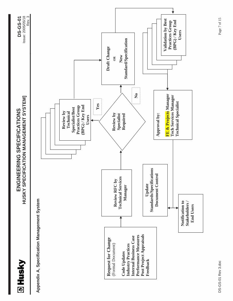
6.1 Whenever changes, additions or deletions are deemed necessary as a result of changes to codes, standards, reference documents or requests for change, the Specification shall be revised following the
process shown in Appendix A.
6.2 The Specification Manager, with the support of appropriate technical specialists, and selected end-users
will ensure the change is effectively reviewed, finalized and approved.
ENGINEERING SPECIFICATIONSHUSKY SPECIFICATION MANAGEMENT SYSTEM
DS-GS-01Issue: 2005/05/18
Rev. 3
DS-GS-01 Rev 3.doc Page 5 of 15
6.3 Revisions to a specification shall be highlighted in yellow for the current revision. Previous
highlighting will be removed from any future revision.
6.4 The revision shall be recorded on the revision status page of the Specification.
6.5 The revised Specification shall be posted on Husky’s Intranet and all old revisions shall be removed
from the Intranet. On Husky’s working directory, the old revision electronic copy shall be moved to a “previous revision” folder to which access has been restricted to the document controller to avoid
misuse and shall be used for reference purposes only.
6.6 The document controller shall update the Specification Register accordingly and retain change
documentation in the specific specification file.
6.7 The superseded master hard copy shall be replaced by the revised specification, and the removed
specification shall be stamped or marked “SUPERSEDED” by document controller and retained in the
file.
6.8 Revised specifications issued to a contractor and/or supplier shall be identified on the document
transmittal as revised specifications if they have been previously issued as an earlier revision.
6.9 It is the responsibility of the contractor and/or supplier to determine any effect the revised specification shall have on work in progress and to advise Husky accordingly.
6.10 The contractor and/or supplier are responsible for the removal and destruction of all obsolete
specifications in their possession.
7.0 Deviation Requests
7.1 Technical deviations to the standards/specifications for a specific application or project are acceptable
when appropriate justification for improved overall fit for purpose or cost reduction is established.
7.2 Husky project leaders or EP contractors may generate deviation requests. All proposed changes (e.g., identified during preparation of design and procurement documents, inspection at a
manufacturer's site or during site construction activities, etc.) shall be properly documented, controlled
and submitted for approval utilizing the applicable forms appended to this guideline.
7.3 Deviation Requests shall be numbered as follows:
DR - XX
Sequential Number
7.4 The document controller shall maintain a deviation request filing system and shall provide the next
available sequential number to the originator of a specification deviation request. All deviations shallbe recorded on the Specification Deviation Request Register form (Appendix E).
7.5 The following elements must be included in a Specification Deviation Request:
• Deviation request number
• Project name and number (as applicable)
• Specification number

ENGINEERING SPECIFICATIONSHUSKY SPECIFICATION MANAGEMENT SYSTEM
DS-GS-01Issue: 2005/05/18
Rev. 3
DS-GS-01 Rev 3.doc Page 6 of 15
• Excerpt taken from the original specification of the impacted content
• Description of the deviation
• Justification and Implications
• Requestor and Project Leader names
• Supporting documentation
7.6 The requestor shall complete the general information in sections A, B and C of the Specification
Deviation Request form (Appendix C) and the Specification Deviation Request Checklist form(Appendix D) and submit by hard copy or email.
7.7 The appropriate manager, as detailed in Sections 4.2 and 4.3, shall review the Specification Deviation
Request along with all supporting documentation, with any of the following persons as deemed
appropriate prior to approval:
• Discipline technical specialist
• Health, safety & environment representative
• Operations & maintenance representative
• Procurement representative
• Quality assurance specialist
7.8 Once Husky has approved or rejected a deviation request, a copy of the completed and signed
Specification Deviation Request form shall be distributed to the requestor, project leader and document
controller.
7.9 Contractors and/or suppliers shall request deviations through the project leader or engineering
procurement contractor.
7.10 All approved Specification deviation requests shall be retained in the project data books.
8.0 Appendices
Appendix A, Specification Management System
Appendix B, Specification Register
Appendix C, Specification Deviation Request
Appendix D, Specification Deviation Request Review Checklist
Appendix E, Specification Deviation Request Register
Appendix E, External Website Management
EN
GIN
EE
RIN
G S
PE
CIF
ICA
TIO
NS
HU
SK
Y S
PE
CIF
ICA
TIO
N M
AN
AG
EM
EN
T S
YS
TE
M]
DS
-GS
-01
Issue:
2005/0
5/1
8R
ev.
3
DS
-GS
-01 R
ev 3
.doc
Pag
e7 o
f 1
5
Ap
pen
dix
A,
Sp
ecif
icati
on
Man
ag
em
en
t S
yste
m
Req
ues
t fo
r C
han
ge
(Form
al D
ocu
men
t)
Cod
e U
pd
ate
s
Ind
ust
ry P
ract
ices
Inte
rnal
Bu
sin
ess
Case
Per
form
an
ce M
easu
res
Post
Pro
ject
Ap
pra
isals
Fee
db
ack
Up
date
Sta
nd
ard
s/S
pec
ific
ati
on
s
Docu
men
t C
on
trol
Rev
iew
RF
C b
y
Tec
hn
ical
Ser
vic
es
Man
ager
Dra
ft C
han
ge
OR
New
Sta
nd
ard
/Sp
ecif
icati
on
Ap
pro
val
by:
FE
& P
roje
cts
Man
ager
Tec
h S
ervic
es M
an
ager
Tec
hn
ical
Sp
ecia
list
Noti
fica
tion
to
Sta
keh
old
ers
/
En
d U
sers
Rev
iew
by
Sp
ecia
list
Req
uir
ed
Rev
iew
by
Tec
hn
ical
Sp
ecia
list
/Bes
t
Pra
ctic
es G
rou
p
(BP
G)
/ K
ey E
nd
Use
rs
Vali
dati
on
by B
est
Pra
ctic
es G
rou
p
(BP
G)
/ K
ey E
nd
Use
rs
Yes
No

ENGINEERING SPECIFICATIONSHUSKY SPECIFICATION MANAGEMENT SYSTEM]
DS-GS-01Issue: 2005/05/18
Rev. 3
DS-GS-01 Rev 3.doc Page 8 of 15
Appendix B, Specification Register
Spec. No. Description Revision Date Online Location Note

ENGINEERING SPECIFICATIONSHUSKY SPECIFICATION MANAGEMENT SYSTEM]
DS-GS-01Issue: 2005/05/18
Rev. 3
DS-GS-01 Rev 3.doc Page 9 of 15
Appendix C, Specification Deviation Request
Company/Department: Deviation Request No:
Project Name: Project No:
Location: Specification No.:
Subject: Date Requested:
SECTION A: (Excerpt Taken From the Husky Specification )
SECTION B: (Description of Deviation)
Change Made Change Proposed
Recommended Specification (please list below)
SECTION C: (Justification and Implications)
Requested By: Name: Signature:
Project Leader: Name: Signature:
SECTION E: (Husky Remedial Action)
Approved Conditionally Approved Rejected
Reviewed By: Name: Signature:
Approved By: Name: Signature:
Attachments: Specification Deviation Request Review Checklist

ENGINEERING SPECIFICATIONSHUSKY SPECIFICATION MANAGEMENT SYSTEM]
DS-GS-01Issue: 2005/05/18
Rev. 3
DS-GS-01 Rev 3.doc Page 10 of 15
Appendix D, Specification Deviation Request Review Checklist
Company/Department: Deviation Request No:
Project Name: Project No:
Location: Specification No.:
Subject: Date Requested:
Originated By: Husky EP Contractor Supplier Contractor
Design Implications (List affected documents, if any):
Health, Safety & Environment Implications:
Reliability/Operational Performance Implications:
Maintenance Implications:
Spares and Interchangeability Implications:
Cost and Schedule Implications: (Attach breakdown comparative costs, if applicable)

ENGINEERING SPECIFICATIONSHUSKY SPECIFICATION MANAGEMENT SYSTEM]
DS-GS-01Issue: 2005/05/18
Rev. 3
DS-GS-01 Rev 3.doc Page 11 of 15
Appendix E, Specification Deviation Request Register
Deviation No. Spec. No. Work No. Originator Date Description Result Ref. Doc.

ENGINEERING SPECIFICATIONSHUSKY SPECIFICATION MANAGEMENT SYSTEM]
DS-GS-01Issue: 2005/05/18
Rev. 3
DS-GS-01 Rev 3.doc Page 12 of 15
Appendix F, External Website Management
Site Security:
1. The company hosting the website is the same one Husky uses for the corporate web site. This means
that we do not have to allow anyone into the Husky network to access data.
2. The external Engineering Specification website has a security certificate which encrypts the
connection between the user and the site. This serves to protect the passwords from computer
hackers.
3. The website entry page (Figure 1) is without any branding. A user has to log in before he can view
any titles or content of the site.
4. The user must accept Husky’s legal agreement before being allowed to log in to the website
(Figure 2). The user cannot view anything on the site without being logged in. Until the user accepts
the legal agreement, the only page the user can see when logged in is the legal agreement
(Figures 2 & 3). Once the legal agreement is accepted, the user can navigate the site (Figure 4).
Future log-ins will not prompt for acceptance of the agreement.
5. Each company (vendor, supplier or engineering contractor) will be issued a user identification and
password to access the site.
6. The Document Controller (Administrative Assistant, Corporate Technical Services) will control
access to the website, under the direction of the Engineering and Project Management team, by
issuing usernames and passwords, and will also delete access to the site as directed.
7. The website automatically creates a record of what is viewed and downloaded from the site by
username.
Site Administration:
1. The Document Controller maintains the engineering specifications on the Husky Intranet site
location (Engineering and Project Management web page), and on the Husky Engineering
Specifications external website.
2. The external website has an e-mail function to notify all users if a document of the site has been
revised. This allows Husky to guarantee that if a specification or document on the website has
changed, that all users are aware of the most current revision.
3. On an annual basis, the Document Controller will verify with the Engineering and Project
Management team that all users registered with access to the external website should retain that
access.

ENGINEERING SPECIFICATIONSHUSKY SPECIFICATION MANAGEMENT SYSTEM]
DS-GS-01Issue: 2005/05/18
Rev. 3
DS-GS-01 Rev 3.doc Page 13 of 15
Figure 1:
Figure 2:

ENGINEERING SPECIFICATIONSHUSKY SPECIFICATION MANAGEMENT SYSTEM]
DS-GS-01Issue: 2005/05/18
Rev. 3
DS-GS-01 Rev 3.doc Page 14 of 15
Figure 3:
Figure 4:

ENGINEERING SPECIFICATIONSHUSKY SPECIFICATION MANAGEMENT SYSTEM]
DS-GS-01Issue: 2005/05/18
Rev. 3
DS-GS-01 Rev 3.doc Page 15 of 15
Figure 5:

ENGINEERING SPECIFICATIONS
PIPELINE DESIGN GUIDELINES
DS-PL-01
Rev Date Description AuthorChecked
By
Approval
Technical
Approval
Management
0 2002/12/23 Issued for use. RP JK
1 2003/01/17 Issued for use. RP JK

ENGINEERING SPECIFICATIONSASME PIPING
BHPS-PF-01
Issue: 2005/09/15Rev. 4
SERVICE: HYDROCARBON PROCESS (sweet service) CLASS: 300
TEMPERATURE: -29 to 149°C (-20 to 300°F) Notes 11 CODE: ASME B31.3 RATING: ASME/ANSI B16.5
TEST PRESSURE: 7 653 kPag (1 110 psig) min.
for 1 hour
C.A.: 1.6 mm (0.0625 in)DESIGN PRESSURE: 5 102 kPag (740 psig) @ 38ºC (100ºF),
Design pressure derates with temperature per ratings of ASME B16.5MATERIAL & TESTING: See Husky Specification PS-MW-01 Welding
DO NOT USE SPECIFICATION AFTER DECEMBER 31, 2006. ALWAYS CHECK WITH HUSKY FOR POSSIBLE UPDATES PRIOR TO USE.
H:\MANDY\2005\ENGINEERING SPECS 2005\INTERNET SPEC CD\HUSKY SPECS - WORD FORMAT\PIPING FOR FACILITIES\SWEET SERVICE - ASME B31.3 PIPING\BH.DOC
Page 1 of 2
.PIPE
NPS RATING END CONNECTIONS DESCRIPTION NOTES
1/2 to 3/4 Sch 160 Scrd. Sch 80 for SW only ASTM A106 Grade B (SMLS) PE 1, 3
1 to 1-1/2 Sch 80 (XS) Scrd/SW ASTM A106 Grade B (SMLS) PE 1, 3
2 to 14 Sch STD BW/RF ASTM A106 Grade B (SMLS) BE 12
16 to 20 Sch XS BW/RF ASTM A106 Grade B (SMLS) BE
FITTINGS
ITEM NPS RATING CONN. DESCRIPTION NOTES
CAP 1/2 to 1-1/2 Class 3 000 Scrd ASTM A105 3
2 to 20 Per pipe above BW ASTM A234 Grade WPB 4
COUPLING 1/2 to 1-1/2 Class 3 000 Scrd ASTM A105, Full & Half 3
CROSS 1/2 to 1-1/2 Class 3 000 Scrd ASTM A105 3
ELBOW 1/2 to 1-1/2 Class 3 000 Scrd ASTM A105, 45° & 90° 3
2 to 20 Per pipe above LR, BW ASTM A234 Grade WPB, 45° & 90°, Straight & Reducing 2, 4
ELBOLET 1/2 to 1-1/2 Class 3 000 Scrd ASTM A105 5
FLANGE 1 to 1-1/2 Class 300 Scrd ASTM A105, Bored to suit Pipe
2 to 20 Class 300 RFWN ASTM A105, Bored to suit Pipe
NIPPLE 1/2 to 1-1/2 Per pipe above Scrd ASTM A106 Grade B (SMLS), 100 mm long min., TBE 1
REDUCER 2 to 20 Per pipe above BW ASTM A234 Grade WPB, Concentric/Eccentric 4
RETURN 2 to 20 Per pipe above LR, BW ASTM A234 Grade WPB 4, 2
SOCKOLET 3/4 to 1-1/2 Class 3 000 SW ASTM A105 5
SWAGE 1/2 to 1-1/2 Per pipe above Scrd or PE ASTM A105 or A106 Gr. B (SMLS), Match Pipe & Connection. 1, 6
TEE 1/2 to 1-1/2 Class 3 000 Scrd ASTM A105 3
2 to 20 Per pipe above BW ASTM A234 Grade WPB, Straight & Reducing 4
THREDOLET 3/4 to 1-1/2 Class 3 000 Scrd ASTM A105 5
UNION 1/2 to 1-1/2 Class 3 000 Scrd ASTM A105 7
WELDOLET 2 to 6 Per pipe above BW ASTM A105 5
VALVES – For Details Refer to PS-PF-03
ITEM SIZE RATING CONN. SHORT DESCRIPTION (Note 13)VALVE IDENTIFICATION
NUMBER
BALL 1-1/2 & smaller Class 2000 Scrd A105 body, Cr. Pltd. trim VB-2002-W8 Note 11
2 to 20 Class 300 RF WCB body, Cr. Pltd. trim VB-301-W8 Note 11
CHECK 1-1/2 & smaller Class 800 Scrd A105 body, No.8 trim to API 602 VC-812 (or 822) -W8
2 to 16 Class 300 RF WCB body, No.8 trim to API 600 VC-301-W8

ENGINEERING SPECIFICATIONSASME PIPING
BHPS-PF-01
Issue: 2005/09/15Rev. 4
SERVICE: HYDROCARBON PROCESS (sweet service) CLASS: 300
TEMPERATURE: -29 to 149°C (-20 to 300°F) Notes 11 CODE: ASME B31.3 RATING: ASME/ANSI B16.5
TEST PRESSURE: 7 653 kPag (1 110 psig) min.
for 1 hour
C.A.: 1.6 mm (0.0625 in)DESIGN PRESSURE: 5 102 kPag (740 psig) @ 38ºC (100ºF),
Design pressure derates with temperature per ratings of ASME B16.5MATERIAL & TESTING: See Husky Specification PS-MW-01 Welding
DO NOT USE SPECIFICATION AFTER DECEMBER 31, 2006. ALWAYS CHECK WITH HUSKY FOR POSSIBLE UPDATES PRIOR TO USE.
H:\MANDY\2005\ENGINEERING SPECS 2005\INTERNET SPEC CD\HUSKY SPECS - WORD FORMAT\PIPING FOR FACILITIES\SWEET SERVICE - ASME B31.3 PIPING\BH.DOC
Page 2 of 2
ITEM SIZE RATING CONN. SHORT DESCRIPTION (Note 13)VALVE IDENTIFICATION
NUMBER
GATE 1-1/2 & smaller Class 800 Scrd A105 body, No.8 trim to API 602 VG-802-W8
2 to 16 Class 300 RF WCB body, No.8 trim to API 600 VG-311-W8
GLOBE 1-1/2 & smaller Class 800 Scrd A105 body, No.8 trim to API 602 VO-802-W8
2 to 16 Class 300 RF WCB body, No.8 trim to API 600 VO-301-W8
NEEDLE 3/4 X 1/2 Class 6 000 MNPT x FNPT A105 body & SS trim VN-6004-W10
MISCELLANEOUS
ITEM SIZE RATING CONN. DESCRIPTION NOTES
BLIND 2 to 20 Class 300 RF ASTM A105 / A516 Grade 70 10
GASKET 2 to 20 Class 300 RF Spiral wound 304 SS, flexible graphite filler 9
NUTS ASTM A194 Grade 2H, 2 nuts per stud
STUDASTM A193 Grade B7
with Jet-Lube Moly-Mist Spray Lubricant or equal
ORIFICE FLANGES 2 to 12 Class 300 RF ASTM A105, bored to suit c/w 1/2 in taps and jack bolts 8
PLUG 1/2 to 1-1/2 Class 3 000 Scrd Hex Head, ASTM A105 3
TUBING 3/8 to 1/2 in OD 0.035 in wall Tube/ScrdA179 Electrogalv. CS or SS with Swagelok/CPI fittings -
Cad. pltd
NOTES
1 Sch. XXH weight nipples and swages for compressor or pump service (vibrating)
2Short radius elbow and returns shall not be used unless they satisfy the specification of the pipe and pressure rating restrictions imposed by ASME
B16.28, Para. 2 (derated to 80% max. allowable stress value)
3 Forged steel fitting to ASME B16.11, Socket Weld (SW) for process GLYCOL piping. Thread Sealant Jet-Lube TF-15 or equal
4 Buttwelding fitting to ASME B16.9
5 Forged C.S. branch outlet fittings to MSS SP-97, consult Branch Connection Chart for extent of application
6 Swage(d) nipples and bull plugs to MSS SP-95
7 Steel pipe unions to MSS SP-83
8 Orifice flanges to ASME B16.36
9 Gaskets to ASME B16.20
10 Blinds (“line blanks”) to API Std 590
11 Temperature limitations see Husky Specification DS-PF-03 Guide to Valve Application
12 Use Sch 80 (XS) for NPS 2 compressor piping
13 All valves shall meet ASME B16.34 requirements. Ball valves fire tested to API 607 4.


ENGINEERING SPECIFICATIONSPIPELINE DESIGN GUIDELINES
DS-PL-01Issue: 2003/01/17
Rev. 1
H:\HUSKY SPECS FINALIZED VERSION\DS-PL-01.DOC Page 1 of 21
Comments on this Specification from all users are encouraged. Please send comments and suggestions to
1.0 Scope
1.1 This Specification outlines the basic practices for the design of the required steel pipe and fittings for apipeline. The design of pig traps is not discussed in this Specification.
2.0 Reference Documents
2.1 The following regulations, codes, standards, and specifications define the minimum requirementsacceptable and shall apply except as modified by this Specification. All regulations, codes, standards,and specifications shall be the latest published revision in effect at the time of purchase. In all caseswhere more than one regulation, code, standard or specification applies to the same conditions, themost stringent one shall apply. Conflicts among any of the provisions of these listed codes, standards orspecifications shall be referred to Husky for resolution.
2.2 Industry Reference Documents
Canadian Standards Association (CSA)
CSA Z169Aluminum Pipe and Pressure Systems
CSA Z662Oil & Gas Pipeline Systems
CSA Z245.1Steel Line Pipe
CSA Z245.11Steel Fittings
CSA Z245.12Steel Flanges
CSA Z245.15Steel Valves
The Pipeline Act
The Energy Utilities Board (EUB) Pipeline Regulations
Gas Processors Suppliers Association (GPSA)
Engineering Data Book, Volumes I & II
Corporate Reference Documents
PS-PL-05 Line Pipe Specification – Sour Service
DS-MW-01 Low Temperature Guidelines

ENGINEERING SPECIFICATIONSPIPELINE DESIGN GUIDELINES
DS-PL-01Issue: 2003/01/17
Rev. 1
H:\HUSKY SPECS FINALIZED VERSION\DS-PL-01.DOC Page 2 of 21
3.0 Design Parameters
3.1 General
3.1.1 There are four basic fluid design parameters that are required to complete the mechanical design ofpipelines. They are design pressure, design temperature, type and phase of the fluid, and H2S content ofthe fluid.
3.1.2 Maximum Operating Pressure (MOP)
3.1.2.1 MOP is the maximum pressure limit for the pipeline under operating conditions. The MOP isestablished by the owner and designer and is reported to the governing regulatory agency in theapplication for the pipeline licence.
3.1.2.2 The pipeline must be qualified by pressure testing at a pressure higher than the MOP The requiredpressure multiplier is set either by the regulator directly or by reference to codes or standards. If theappropriate pressure for the desired MOP is not achieved at the time of testing, the regulator will assignthe highest MOP that can be allowed for the pressure that was achieved. Once the MOP is establishedfor a pipeline it cannot be increased without performing another pressure test, therefore, it is extremelyimportant to choose the MOP wisely.
3.1.2.3 The licenced MOPs of pipelines that receive fluid from, or deliver fluid to a pipeline will influence thechoice of MOP for the new line. Regulatory agencies and design codes generally require that lowerpressure pipelines be protected from overpressure by higher pressure lines, through the use of checkvalves and pressure limiting valves. The cost and inconvenience of installing and maintaining thesedevices can often be avoided by adjusting the MOP of the new line to coincide with the existing lines.
3.1.3 Design Pressure
3.1.3.1 Design pressure is used by the engineer or designer, primarily for stress calculations, pipe andcomponent selection. The design pressure must always be at least equal to the MOP
3.1.3.2 The Owner or engineer may choose to design at a pressure higher than the MOP to allow for flexibilityin the design such as future higher operating pressure. Other circumstances which may dictate a higherdesign pressure include significant pressure variation along the pipeline due to elevation differences,acceleration, water hammer, slug flow and pigging operations.
3.1.3.3 Designers should also keep in mind that the design factors used for the pipeline should be chosen withregard to potential future conditions such as urban development encroaching on the pipeline.
3.1.4 Normal Operating Pressure
3.1.4.1 From an operational viewpoint, a pipeline can only be feasibly operated at a maximum pressure of 90%of the MOP. Pipelines may require high-pressure shutdown devices, which limit the maximum amountof pressure that can be imparted to a pipeline. These shutdown devices are usually set to activate at apressure of 0.98 to 1.0 times the MOP of the pipeline. In order to prevent nuisance shutdowns,pipelines would be normally operated at a pressure of 90% of the MOP or at least 350 kPa less than theMOP of the pipeline. Fluid flow calculations should use the normal operating pressure. For example, ifit is determined that an operating pressure of 10 000 kPa is required to transport 1000 X 10
3 m³ per day
of gas, then the MOP should be at least 11 000 kPa.
ENGINEERING SPECIFICATIONSPIPELINE DESIGN GUIDELINES
DS-PL-01Issue: 2003/01/17
Rev. 1
H:\HUSKY SPECS FINALIZED VERSION\DS-PL-01.DOC Page 3 of 21
3.1.5 Unsteady Operating Pressures
3.1.5.1 On two-phase pipelines with low vapor phase velocities and a potential for "slug flow", there may be atendency for these types of pipelines to operate with an unsteady “pulsating” pressure. The MOP ofthese pipelines should be established high enough to allow for these pressure peaks. Also, if a two-phase pipeline is to be pigged, the required pipeline operating pressure during the pigging operationcould be higher than the MOP due to the hydrostatic head of the liquid in front of the pig resulting fromelevation changes in the pipeline. If a pig happens to get stuck in the line, it is desirable to be able toincrease the system pressure to try and dislodge the stuck pig. Therefore, again, a higher MOP may berequired to safely operate the pipeline while pigging. The establishment of the pipeline MOP in thesecases should be discussed with the field operations office.
3.1.6 Standard Design Pressures
3.1.6.1 Pipeline designers will often decide to set the MOP of a pipeline system at the maximum pressurerating of the ANSI flange class, e.g., 9 930 kPa (Class 600 rating), even though the required pressurefor hydraulic design may be lower. This practice usually adds some flexibility and safety to the design,and does not usually result in a substantial cost for short pipeline systems. In longer pipeline systems,the cost of the extra wall thickness will be much larger, therefore, the designer should consider theeconomics of choosing to design at one of the ANSI Class pressures.
3.2 Design Temperatures
3.2.1 Design Temperature
3.2.1.1 The minimum design temperature used for oil and gas pipelines is -18°C for buried pipe and -45°C forabove-ground pipe without heat tracing.
3.2.2 Maximum Design Temperature
3.2.2.1 The maximum design temperature for pipelines is usually set at 5°C to10°C higher than the maximumexpected normal operating temperature. The temperature rating of the external coating system must beat least equal to the maximum design temperature. The maximum temperature for standard CSAZ245.21 system A1 and A2 polyethylene coating is 60 to 65
oC, and for system B Coating is 85
oC.
3.2.3 Design Temperatures Above 65°C
3.2.3.1 If higher maximum temperatures are required, fusion bond epoxy and liquid epoxy coatings areavailable with temperature ratings ranging from 75°C to 115°C. Please note that consideration shouldbe given to high temperature coatings for pipelines that may be subject to hot oil treatments orsteaming such as emulsion lines.
3.2.4 Line Heater Applications
3.2.4.1 Where gases and liquids are to be transported at elevated temperatures and are heated in indirect firedglycol-bath type line heaters, the discharge temperatures will be in the order of 40°C to 80°C. Thesepipelines will almost always require insulation to preserve the fluid temperature during transport.

ENGINEERING SPECIFICATIONSPIPELINE DESIGN GUIDELINES
DS-PL-01Issue: 2003/01/17
Rev. 1
H:\HUSKY SPECS FINALIZED VERSION\DS-PL-01.DOC Page 4 of 21
3.3 Type and Phase of Fluid
3.3.1 Multiphase Fluids
3.3.1.1 The problem of predicting flow line pressure losses (or head loss) due to friction in multiphase flow isparticularly complex and requires knowledge of the pipeline elevation profile and phase interactionrelations for reasonably accurate calculations. Manual calculations are provided in the Gas ProcessingSupplier’s Association (GPSA) Databook, Section 17, which can be used for shorter lines, however,most designers will employ one of the commercially available flow simulation programs when workingwith multiphase pipelines.
3.3.1.2 A long standing rule-of-thumb for wet sour service pipelines with high gas-liquid ratios is to keep thesuperficial gas velocity between 3 to 6 m/s in order to help sweep liquids from the low spots in thepipeline without approaching the erosional velocity. Maximum liquid slug size should be considered inmultiphase pipelines.
3.4 Hydrogen Sulphide Content
3.4.1 CSA Sour Service Definition
3.4.1.1 CSA Standard Z662 considers a gas pipeline to be in “sour service” if the gas being transportedcontains more than 0.35 kPa partial pressure of hydrogen sulphide (H2S). A liquid pipeline isconsidered to be in “sour service” if the system pressure is below 1 400 kPa and the vapour phase ofthe liquid contains more than 50 mol/kmol of H2S or if the system pressure is greater than 1 400 kPaand the partial pressure of the H2S in the vapour phase is greater than 70 kPa. Refer to CSA StandardZ662-99, Clause 5.4 Sour Service.
3.4.1.2 In Alberta, the EUB definition of “sour natural gas service” is 10 mol/kmol at any pressure but this isfor licencing purposes. The EUB has additional regulatory and design requirements for sour natural gaspipelines. Set back distances separating sour natural gas pipelines from developments are outlined inInterim Directive, ID 81-30.
3.4.1.3 The CSA codes warn pipeline designers that corrosion problems can occur at H2S concentrations lowerthan those cited above if other constituents such as steam, carbon dioxide (CO2), and salts in water arepresent in the pipeline fluid. However, the codes do not tell you what you should do if the abovesituation exists. As a suggestion, the designer should enlist the services of a corrosion consultant toperform some corrosion potential tests and evaluations. The results of these tests may influence thedesigner to specify the pipeline as sour service at a lower H2S level than what has been cited above oreven if no H2S is present.
3.4.2 Husky Sour Service Determination
3.4.2.1 Specification PS-PL-05 Line Pipe Specification – Sour Service defines two categories of sour service,Region 1 Transition Sour and Region 2 Sour, that are established using hydrogen partial pressure andinsitu pH of condensed water.
3.4.2.2 The category of sour service is used to define material and quality control requirements.
3.4.2.3 It is required that the Husky responsible engineer establishes the category of sour service to be used.

ENGINEERING SPECIFICATIONSPIPELINE DESIGN GUIDELINES
DS-PL-01Issue: 2003/01/17
Rev. 1
H:\HUSKY SPECS FINALIZED VERSION\DS-PL-01.DOC Page 5 of 21
4.0 Line Pipe Design and Specification
4.1 Minimum Diameter
4.1.1 Pipe diameter is determined by velocity and pressure considerations. See appendix A, Equation 3.0.
4.1.1.1 For crude oil and natural gas pipelines, the minimum size generally used is 88.9 mm O.D. For crude oilsystems, a minimum of 88.9 mm flow lines is preferred, because they are less susceptible to waxplugging problems and are easier to pig. Fuel gas supply pipelines are an exception to this rule; they areoften a minimum of 60.3 mm in diameter.
4.1.2 Two-Phase Oversizing Caution
4.1.2.1 Two-phase systems with vapour phase flow rates less than 2.5 m/s are prone to operate in the "slugflow" regime, resulting in plant inlet operating problems. Pay special attention to the pipeline turndownrequired, due to both gas contract restrictions and natural well flow rate decline.
4.2 Pipe Wall Thickness and Specified Minimum Yield Strength
4.2.1 Influence of Pipe Stresses
4.2.1.1 The required wall thickness for the line pipe is determined by the hoop stress and longitudinal stresscreated by the pipeline fluid pressure and temperature.
4.2.2 Large Longitudinal Stresses
4.2.2.1 Buried pipelines (restrained) that are constructed in winter conditions are subjected to longitudinalcompressive stress when the line warms up to operating temperature. This is particularly important forlines transporting heated fluids (e.g. Line Heated System or Thermal Project). The temperature rangemust be taken into account in selecting the pipe wall thickness and grade. (Refer to CSA Standard Z662design equations for ambient temperature at time of restraint and “T2 = maximum operatingtemperature”). This temperature range has a large influence on the design of a heated pipelineconstructed in winter conditions. The following are ways to reduce the impact of this constraint on thewall thickness:
• Specify a higher specific minimum yield strength (SMYS)
• Reduce the maximum operating temperature if it is conservative on the high side
• Increase the design minimum ambient temperature and consider curtailing pipeline construction(lower-in and backfill) when the actual ambient temperature is less than the specified temperature
• For short pipelines, pre-stressing of pipe.
• Non linear analysis in combination with limit state design, utilizing special computer program.
4.2.3 Hoop Stress Criteria
4.2.3.1 When longitudinal stress is not the overriding constraint, the minimum required pipe wall thickness iscalculated from the hoop stress formula: See appendix A, Equation 1.0.
4.2.4 Specified Minimum Yield Strength (SMYS)
4.2.4.1 The specified minimum yield strength (SMYS) is the minimum yield stress that the material must beable to withstand, i.e., continue to exhibit elastic properties, under a tensile test (up to 0.5% tensile

ENGINEERING SPECIFICATIONSPIPELINE DESIGN GUIDELINES
DS-PL-01Issue: 2003/01/17
Rev. 1
H:\HUSKY SPECS FINALIZED VERSION\DS-PL-01.DOC Page 6 of 21
strain limit for CSA Standard Z245.1 Steel Line Pipe) for the standard to which the material is beingqualified. Thus, “SMYS” is often termed synonymous with “grade”; as in CSA Standard Z245.1 Grade290 has an SMYS of 290 MPa and all pipe which intends to meet the grade must have an SYMSgreater than 290 MPa.
4.2.4.2 In stress equations where a value of yield strength is required, published SMYS is to be used. Use ofactual yield strength values from material test reports is not allowed. However, the mill can re-certifypipe based on obtained tensile properties per CSA 8.2.1.1, 8.2.2.4 and Table 8.
4.2.4.3 Appendix C lists the SMYS for commercially available steel line pipe.
4.2.5 Tensile Strength
4.2.5.1 Tensile strength, also referred to as ultimate tensile strength or maximum yield strength, is the stress atwhich the material exhibits actual tensile failure. Ultimate tensile strength (breaking strength) shouldnever be substituted for SMYS.
4.2.6 SMYS and Wall Thickness (WT) Comparison
4.2.6.1 Generally, using the highest SMYS pipe available will tend to result in the lowest cost pipe materialpossible being specified. The cost savings resulting from using thinner walled pipe are greater than theadditional cost for the higher SMYS, however, very thin walled pipe (less than 3.18 mm) can be moreexpensive to weld and is more prone to brittle failure.
4.2.7 SMYS for Sour Service
4.2.7.1 For sour service pipes, the maximum SMYS usually specified is Grade 359 MPa and in case of larger
pipelines (≥NPS12), Grade 386MPa can be used. It is generally accepted that if higher SMYS pipematerial is used, it could be subject to stress corrosion cracking and thus, premature failure.
4.2.8 SMYS for Sweet Service
4.2.8.1 Conceivably, for sweet systems, Grade 386 MPa or higher SMYS could be specified; but for systemsconsistency and surplus pipe handling, Grade 359 MPa is the highest SMYS that should be specifiedunless there is a specific economic or design advantage to using a higher SMYS.
4.2.9 SMYS for Exceptional Cases
4.2.9.1 Examples of exceptions may be for a very high pressure water injection line, a high pressure gas linefor a gas cycling scheme, seamless high pressure steam lines used for cyclic injection in heavy oilapplications, or a very long sweet gas or condensate pipeline where reduced wall thickness using386MPa pipe might represent a large capital saving. Note, these systems are classified as sweet service.
4.2.10 Calculation of WT
4.2.10.1 Table 8.1 of CSA Standard Z245.1 lists the standard commercially available pipe wall thicknesses forERW pipe. The pipe wall thickness to be specified for purchasing should be the next commerciallyavailable pipe wall thickness above the calculated minimum. If it happens that the calculated minimumpipe wall thickness is slightly larger than a commercially available wall thickness, the designer shouldconsider the system impact (flow capacity, operating characteristics, etc.) and cost trade-offs oflowering the MOP so that the thinner pipe can be used. On the other hand, if the commercially

ENGINEERING SPECIFICATIONSPIPELINE DESIGN GUIDELINES
DS-PL-01Issue: 2003/01/17
Rev. 1
H:\HUSKY SPECS FINALIZED VERSION\DS-PL-01.DOC Page 7 of 21
available pipe wall thickness specified for purchase is greater than the wall thickness, the designercould increase the pipeline MOP and thereby increase the system flow capacity for no extra cost(except for a slightly higher required pressure test) recognising the limitations due to flange rating.
4.2.11 Minimum WT
4.2.11.1 The designer is cautioned not to arbitrarily rationalise a thinner wall thickness by using a higher SMYSgrade pipe. Increasing the SMYS of a pipe only very marginally increases a pipe’s resistance tobuckling and allowable bending stress. Appendix D, Minimum Recommended Pipe Wall Thickness,lists the recommended minimum allowable wall thicknesses.
4.2.12 Longitudinal Stresses Due to Thermal Effects of Buried Pipeline
4.2.12.1 A pipeline buried in normal shear strength soil with normal cover (CSA specified minimum burieddepth) is considered to be fully restrained, which means that when the pipe is subjected to an increasein temperature, the pipe cannot expand along its longitudinal axis due to the soil restraint. In essence,the pipe cannot physically expand when subjected to a temperature change, and therefore causescompressive stress in the longitudinal (axial) direction. See appendix A, Equations 5.0, 5.1 and 5.2.
4.2.13 Longitudinal Stresses Due to Thermal Effects of Surface Pipeline
4.2.13.1 An above-ground system, piping networks is flexible (unrestrained), which allows the pipe to movewhen subjected to thermal expansion. This movement reduces the axial stress and creates bendingstresses at elbows and fittings; however, the overall stresses are usually less. See appendix A,Equations 5.0, 5.1 and 5.2. Since above-ground lines are subject to thermal expansion, considerationshould be given to performing stress calculations at key locations and if the temperature range is largeand the piping geometry is complex this may be best done using a commercial stress analysis program
such as Coade Caesar II®
, or AutoPIPE®.
4.2.14 Cold Installation Temperature Criteria
4.2.14.1 If the pipeline is planned to be installed in cold weather, the designer should determine the added wallthickness required to install the pipeline in the winter. The designer may elect to specify the thickerwalled pipe; the possibility of a project delay necessitating winter construction may warrant the extrapipe costs.
4.2.15 Corrosion Allowance
4.2.15.1 The pipeline designer should take note that a uniform corrosion allowance is not usually added to thepipeline wall thickness in the same manner as is required in surface plant or refinery piping(ASME B31.3). The design factors take into account a safety factor for the type of service but not forcorrosion. On sour service pipelines an additional corrosion allowance is usually not stipulated by codeor standard. This is done because it is recognised that the major forms of corrosion are of a localisednature such as "pitting" and therefore added corrosion allowance for generalized corrosion does notsignificantly help in this case. This does not mean that corrosion can be neglected! On the contrary, thedesigner is obligated to do more than just specify pipe with a “built-in” corrosion allowance; he/shemust make provisions in the design to control corrosion. For carbon steel materials in sour service theseprovisions usually include pigging, inhibitor application and the possibility of line a log corrosionmonitoring because the material and fluid are inherently incompatible from a corrosion standpoint.

ENGINEERING SPECIFICATIONSPIPELINE DESIGN GUIDELINES
DS-PL-01Issue: 2003/01/17
Rev. 1
H:\HUSKY SPECS FINALIZED VERSION\DS-PL-01.DOC Page 8 of 21
4.2.16 Class Location
4.2.16.1 The location factor (L) as defined in Table 4.1 in CSA Standard Z662 also affects the minimum wallthickness for the carrier pipe. When determining the class location designation, due consideration shallbe given to the possibility of future development in the area.
4.3 Notch Toughness Properties
4.3.1 CSA Categories:
4.3.1.1 The type of fluid transported, the minimum design temperature of a pipeline and the design operatingstress will dictate the pipe notch toughness properties required for the pipe material.To determine which category is required, the designer should refer to Table 5.1 in CSA Standard Z662(note the fine print and all of its Section 5.2.2 as well).
4.3.2 Common Misconceptions
4.3.2.1 Husky requires that all sour service pipelines have to be Category II material. However Category IInotch toughness and H2S corrosion resistance are not directly related. There is some potential forsaying that a material with good notch toughness may also be better for H2S corrosion because it wouldbe a higher quality steel, and also true that due to the hazardous nature of H2S the risk of loss islessened if the pipe is less likely to fail due to causes other than corrosion, but the codes or regulationsdo not require Category II in sour service.
4.3.3 Specified Toughness Test Temperature
4.3.3.1 For Category II systems, the notch toughness test temperatures specified for the below ground pipematerial should be -18°C or lower. For above ground piping, -45°C should be the specified notchtoughness temperature for the required pipe, valves and fittings.
4.3.4 Above-Ground Pipe Toughness Requirement
4.3.4.1 Appendix E, Pipe, Valve and Fittings, outlines the suitable material specifications for above groundpiping components in CSA Category I & II service.
5.0 Materials Selection for Line Pipe
5.1 Steel Pipe: Manufactured Types
• Acceptable types of steel pipe for pipelines are electric resistance welded (ERW), and seamless(SMLS). Double submerged arc welded (DSAW) and spiral welded steel pipe for pipelines are notacceptable in either sweet nor sour service.
• Pipe used for pipelines, called “line pipe” is manufactured from flat rolled steel. The flat rolledsteel is slit to appropriate widths and rolled up into coils of “pipe skelp.” The skelp is thentransferred to a pipe mill (sometimes called a rolling mill) where it is unrolled and formed intopipe.
5.1.1 CSA Standard Z245.1, Electric Resistance Welded (ERW) Pipe
5.1.1.1 ERW pipe is manufactured in accordance with specifications outlined in the CSA Standard Z245.1 forsteel line pipe.

ENGINEERING SPECIFICATIONSPIPELINE DESIGN GUIDELINES
DS-PL-01Issue: 2003/01/17
Rev. 1
H:\HUSKY SPECS FINALIZED VERSION\DS-PL-01.DOC Page 9 of 21
5.1.1.2 The ribbon of skelp is unrolled and fed into the mill where it is cold formed gradually through a seriesof rollers into the pipe shape. The two edges meet, are trimmed and welded together by a high-frequency induction welder using no filler metal. The next roll of skelp is attached to the end of theprevious and so on. The welded pipe is cut into joints after welding. The welded connections made toattach the successive coils of skelp are marked for cut out and discarded.
5.1.2 API 5L and API5 LX ERW
5.1.2.1 Alternatively, API 5L and API 5LX ERW pipe can be used in Category I pipelines. However, sinceCSA Standard Z245.1 pipe is readily available, API pipe is not usually specified. For sour servicesystems pipe meeting CSA Standard Z245.1, sour service requirements per Husky specificationPS-PL-05 Line Pipe Specification – Sour Service.
5.1.3 Seamless Pipe (SMLS)
5.1.3.1 Seamless pipe is used almost exclusively in above ground refinery and plant piping designed to ASMEB31.3, and it follows that “seamed pipe” (ERW, DSAW etc.) is seldom used above ground.
5.1.3.2 Seamless pipe is produced by several methods, all of which are more costly than for seamed pipe.Seamless pipe is not available in the same wide range of grades and thicknesses as “line pipe”,consequently it usually is a higher cost option and is generally only used in limited pipelineapplications such as runs of short length on or near plants, above ground in pipeline compressorstations and areas where the pipeline is being transitioned from “pipeline codes” to “plant codes.”
5.1.3.3 Since above-ground piping generally poses a greater safety hazard, the additional cost of usingseamless pipe is considered warranted. Also, forged butt-weld fittings and flanges, which are usuallyrequired on above ground systems, are more compatible from a wall thickness point of view withASTM seamless pipe as compared to CSA Standard Z245.1 ERW pipe.
5.1.3.4 ASTM seamless pipe is specified for above ground application as A106 Grade B for ambient
temperatures -29°C and higher, and A333 Grade 6 for -29°C to -45°C (low temperature service). The
-29°C limit for A106B does not apply to all thickness and diameters (refer to ASME B31.3).
5.1.3.5 For oilfield steam distribution pipelines designed per CSA Standard Z662 Clause 14 – Seamless pipeper A-106B or Q&T seamless pipe per CSA Standard Z245.1 Grade 359 are used. Husky CTS hascustomised specifications for seamless Q&T Grade 359 pipe and hot bends available.
5.1.4 Aluminium Pipe
5.1.4.1 Aluminium pipe has the following advantages: it is acceptable in sour and carbon dioxide service andin 88.9 mm diameter and less and is available in coils which allows it to be ploughed in very quickly. Itcan also be used to transport produced water but confirmation that the aluminum will not be susceptibleto chloride cracking is imperative, therefore, it is cautioned. With that said, the pipe material is higherin cost than the equivalent steel pipe, and qualified aluminium welders are not as readily available.Explosion type welding with internal sleeve is also commonly done. Aluminium pipe has been usedmost extensively in low-pressure rural gas co-op lines.
5.1.5 Fiberglass Reinforced Pipe (FRP)
5.1.5.1 FRP pipe also has superior corrosion resistance properties as compared to steel. However, FRP pipedoes have pressure limitations and its material cost is greater than the equivalent required steel pipe. In
ENGINEERING SPECIFICATIONSPIPELINE DESIGN GUIDELINES
DS-PL-01Issue: 2003/01/17
Rev. 1
H:\HUSKY SPECS FINALIZED VERSION\DS-PL-01.DOC Page 10 of 21
addition, the basic joining technique for FRP pipe is a threaded connection which is not as reliable as awelded connection and when installing FRP pipe the entire trench length may need to be sandpadded.Because FRP pipeline installations are generally more costly than the equivalent steel pipelineinstallations, FRP lines are not too common. However, the industry has used FRP pipe for salt waterdisposal service which was considered very corrosive but low pressure operation. (See HuskySpecification PS-PL-01 Fiberglass Line Pipe)
6.0 Line Pipe Length
6.1 Standard Lengths
6.1.1 ERW line pipe is available in single, double and triple random lengths. This designation refers to 6 m,12 m and 18 m joint lengths respectively. The word “random” means that a particular joint of pipe maybe plus or minus the stipulated length. The allowable minimum, maximum and average length of jointsin an order are listed in CSA Standard Z245.1.
6.2 Preferred Lengths
6.2.1 For most pipeline systems, it is more cost efficient to specify triple random lengths. The field truckingand welding costs would be about 30% less as compared to using double random length pipe. However,slightly more caution is required by the field crew when handling triple random lengths so as not tobuckle pipe joints while stringing. This is very rarely a problem.
6.2.2 ASTM seamless pipe comes in 6.1 m and 12.2 m joint lengths.
6.3 Pipe Surplus
6.3.1 It has been found from experience that if a pipeline route has been surveyed and “slack chained”, a pipeorder of the slack chain length plus 3% is adequate. If no slack chainage is available, but only a surveydrawing, one should consider ordering the survey drawing length plus 5% surplus. If pipe must beordered from a topographical map routing, one should order the scaled route length from the map plus12%.
7.0 Pipe Specifications for Crossings
When a pipeline crosses roads or highways and major rivers, higher strength or higher wall thicknesspipe material in these specific locations is sometimes required. Generally for foreign pipeline crossings,small creek crossings or telephone cable crossings, there is no requirement or need to change the pipespecification.
7.1 Road and Railroad Crossings
7.1.1 There are two design methods used for road and railroad crossings. One method is to use the line pipethat is the same specification as the rest of the pipeline and protect this pipe (carrier pipe) with anadditional external pipe called a casing pipe. The second method is to upgrade the strength of the linepipe (carrier pipe) by increasing the wall thickness and install the road crossing without a casing pipe.
7.1.2 The use of cased crossings is beginning to fall out of favour due to the difficulties in maintainingcathodic protection through the crossing. Railway companies, however, still usually insist on the casedstyle crossing.

ENGINEERING SPECIFICATIONSPIPELINE DESIGN GUIDELINES
DS-PL-01Issue: 2003/01/17
Rev. 1
H:\HUSKY SPECS FINALIZED VERSION\DS-PL-01.DOC Page 11 of 21
7.2 Casing Pipe Diameter
7.2.1 For cased crossings, the specified casing pipe diameter must be as follows:
• For carrier pipe less than 168.3 mm, the OD of the casing pipe must be at least 50 mm larger thanthe OD of the carrier pipe
• For carrier pipe greater than or equal to 168.3 mm, the OD of the casing pipe must be at least75 mm greater than the OD of the carrier pipe
7.3 Casing Pipe WT
7.3.1 The minimum wall thicknesses required for various casing pipe diameters are shown in CSA StandardZ662. Since the casing pipe is meant to carry only external loads from soil overburden and vehiculartraffic over the road or railroad, unless the road in question is particularly poor or weak soil, theminimum wall thickness for the required casing should be specified.
7.4 Casing Pipe SMYS
7.4.1 The SMYS of the casing pipe should be specified as low as possible. Again, due to the nature of theexternal loads, high SMYS pipe is not required, therefore, Grade 290 MPa SMYS pipe would besufficient in most cases.
7.5 Casing Pipe Length
7.5.1 CSA Standard Z662 gives the minimum length requirements for cased crossings.
7.5.2 Triple random joint lengths should also be specified. Also, when ordering the casing pipe, specify thatthe pipe required is casing pipe; most suppliers provide casing pipe that is mill line pipe rejects(chemistry not quite up to specification, etc.), which is more than suitable for casing. The casingmaterial is lower cost than CSA Standard Z245.1 ERW pipe.
7.6 Uncased Crossing
7.6.1 If an uncased road or railroad crossing is required, the pipe operating hoop stress level for the line pipeunder the road or rail track must be less than the rest of the line. The CSA Standard Z662 and thegovernment transportation authorities have minimum requirements for pipe used in uncased crossings.
7.7 Design Factors for Uncased Crossings
7.7.1 The design factors used for uncased crossing pipe are lower than for general and cased crossings. Thismay mean a greater wall thickness is required. An alternate solution is to increase the SMYS throughthe crossing.
7.8 Minimum WT
7.8.1 The minimum pipe wall thickness required for uncased crossings regardless of SMYS is shown in CSAStandard Z662.
7.9 Quantity of Pipe for Uncased Crossings
7.9.1 When ordering pipe for uncased crossings, the amount of pipe ordered is usually small as compared tothe main line pipe order. Therefore, it is very important to make sure that a sufficient quantity is

ENGINEERING SPECIFICATIONSPIPELINE DESIGN GUIDELINES
DS-PL-01Issue: 2003/01/17
Rev. 1
H:\HUSKY SPECS FINALIZED VERSION\DS-PL-01.DOC Page 12 of 21
ordered. It may be very difficult to obtain “off the shelf” extra, and in all likelihood, if a shortagedeveloped, one would have to case the remainder of the crossings at higher cost. As a general practice,it is suggested if uncased crossings are going to be used, the amount of pipe ordered should be thesurvey width plus 20%. Again, triple random joint lengths are preferred.
7.9.2 If pipe is pulled through bored or drilled crossings consideration should be given to the potential forcoating damage (gouging and abrasion) and whether sacrificial or abrasion resistant coatings arewarranted.
7.10 Marking of Uncased Pipe
7.10.1 One last point that should be noted is that all uncased crossing pipe should be distinctly marked on thepipe coating with paint bands or some other clear distinguishing marking which would prevent fieldmix-ups with the main line pipe (relying on the printed stencilling identifying the pipe is not goodenough). Very often, the uncased pipe is only a few millimetres thicker or exactly the same size withhigher SMYS; to the field crew, the pipe may look all the same to them, and they may install it as such.
7.11 River Crossings
7.11.1 CSA and EUB Requirements
7.11.1.1 Permitting requirements and environmental considerations have influenced the favoured methods forcrossing streams. Significant streams are now predominantly crossed using drilling and boringmethods. Open-cutting is used as a backup method if drilling is unsuccessful or not feasible due togeotechnical aspects or for small creeks with low flow rates.
7.11.1.2 Pipe that is pulled into drilled crossings should be given special attention in regard to the stressesimposed by pulling, and bending. The coating systems should be evaluated in terms of scuffing,abrasion and gouging.
7.11.1.3 The installation of major (wider than 100 m) river crossings tend to be quite costly. A line failure in ariver crossing may be very environmentally detrimental and costly to repair. Therefore, additionaldesign factor of the pipe may be warranted. The CSA codes and EUB regulations allow the operatingcompany to install a river crossing with the same design factors as the rest of the pipeline.
7.12 Preference Design Factor
7.12.1 It is recommended that the design factor for river crossings be derated to the same level as uncasedroad crossings, and the pipe wall thickness increased accordingly. The main purpose of this increasedwall thickness is to provide additional corrosion allowance as well as extra resistance to buckling andbending stress, which can result from handling the pipe with weights, and possibly from river erosiononce the line is installed. It should be noted that additional SMYS does not add to corrosion allowanceand adds only marginally to buckling resistance.
7.13 Spare Lines
7.13.1 Pipelines in critical service may warrant the installation of spare lines at the river crossing to minimizethe downtime and the cost of repairing a damaged line. If spare lines are installed, make sure that thelines are “mothballed” correctly. These spare lines are not usually tied in to the main line but are left“capped” and available for future use if required.

ENGINEERING SPECIFICATIONSPIPELINE DESIGN GUIDELINES
DS-PL-01Issue: 2003/01/17
Rev. 1
H:\HUSKY SPECS FINALIZED VERSION\DS-PL-01.DOC Page 13 of 21
8.0 Instructions for Designing Pipelines
8.1 Data Requirements
• Design Pressure
• Design Temperature (Maximum & Minimum)
• Installation Temperature
• Type and Phase of Fluid
− Fluid Mixtures
• Hydrogen Sulphide Content
− Calculated pH
− Corrosion Allowance
• CO2 content
• Line Pipe Design Data
− Pipe Diameter
− Minimum Pipe Wall Thickness
• Notch Toughness Properties
− CSA Categories
• Material Selection for Line Pipe
− Pipe Joint Length
• Installation Soil Conditions – Special Coatings
8.2 Engineering Tools
8.2.1 There are several engineering tools available for calculation of pipe design. These formulas arereferenced to the above material. They are listed in appendix A, Design Verification Equations.
8.3 Design Steps and Methods
8.3.1 Determine appropriate pipe and fluid properties per section 4.1 of this Specification, MinimumDiameter.
8.3.2 Select the appropriate formulae listed in appendix A. Use the reference material to research yourselection.
8.3.3 Fill in the checklist data sheet in appendix B, Pipeline Design Guidelines Data Sheet.
8.3.4 Document the results.
8.4 Documentation Requirements
8.4.1 A copy of the design notes and calculations shall be documented with the project.

ENGINEERING SPECIFICATIONSPIPELINE DESIGN GUIDELINES
DS-PL-01Issue: 2003/01/17
Rev. 1
H:\HUSKY SPECS FINALIZED VERSION\DS-PL-01.DOC Page 14 of 21
8.4.2 Complete documentation of the pipeline design will include the following:
• Design calculation sheets, for wall thickness, pressure drop and velocity as applicable
• Data used listing any references used for assumptions i.e., pipe material
• Final calculations showing appropriate table
• Design verification

ENGINEERING SPECIFICATIONSPIPELINE DESIGN GUIDELINES
DS-PL-01Issue: 2003/01/17
Rev. 1
H:\HUSKY SPECS FINALIZED VERSION\DS-PL-01.DOC Page 15 of 21
APPENDIX A, DESIGN VERIFICATION EQUATIONS
The calculations of the pipeline wall thickness should be verified by a second engineer and checked by the projectlead mechanical engineer. The project manager must approve the design.
Density
• Equation 1.0 ρ = ×× ×
MW P
T z
a
8 3145.
Specific Gravity
• Equation 2.0 SGMW
MW
gas
air
=
Pipe Diameter
Pipe diameter is determined by pressure drop and velocity considerations:
• Gas lines under 10 km (6.25 mi in length:
− Use the Weymouth equation page17-6 of GPSA Engineering Data Book.
− Limit superficial gas velocity to under 9.144 m/s (30 fps). The formula for superficial gasvelocity is
− Equation 3.0 VQ
d=
×π4 1000
2
2
• Gas lines greater than 10 km (6.25 mi) in length:
− Use Panhandle B Equation, page 17-7 of the GPSA Engineering Data Book.
− The same velocity criteria apply for the shorter lines
• Liquid lines
− Use the Darcy Equation, page 17-3 of the GPSA Engineering Data Book
− Generally velocity is the sizing criteria. Noncorrosive liquids are sized to have a maximumvelocity of less than 3.048 m/s (10 fps), corrosive liquid to less than 1.22 m/s (4 fps).
Wall Thickness Hoop Stress Calculation
• Equation 4.0 t = (PD
2SFJT L) x 10f
-3

ENGINEERING SPECIFICATIONSPIPELINE DESIGN GUIDELINES
DS-PL-01Issue: 2003/01/17
Rev. 1
H:\HUSKY SPECS FINALIZED VERSION\DS-PL-01.DOC Page 16 of 21
Combined Stress Criteria
The following equations are important for pipelines installed in the wintertime, heated pipelines, and pipelinesoperating with hot fluids. The stresses resulting in pipelines due to hoop stress and longitudinal stress due totemperature variance must satisfy the following criteria:
• Equation 5.0 10x2t
PD=S
3-h
• Equation 5.1 ( )L hS = E a - S× ×T - T1 υ
• Equation 5.2
NOTE: If Equation 4.0 is not satisfied, increase the wall thickness, or reduce the design pressure.
a = Linear coefficient of thermal expansion (°C-1)
= 12 x 10-6 °C
-1
d = Internal diameter (mm)D = Outside diameter (mm)E = Modulus of elasticity of steel (MPa); 192,400 MPa for steelF = design factorJ = longitudinal joint factorL = Location FactorMW = Molecular weight (kg / kMol)MWgas = Molecular weight of the gas substance (kg / kMol)MWair = Molecular weight of air = 28.964 kg / kMol
ρ = Density (kg / m³)P = Design pressure (kPa)Pa = Absolute inlet operating pressure (kPaa)Pave = Average pressure (psi)Q = Vapor flow rate (m³ / sec.)S = specified minimum yield strength (Mpa)SG = Specific gravitySh = Hoop stress due to internal pressure (MPa)SL = Longitudinal compressive stress due to thermal expansion (MPa)t = Minimum nominal wall thickness (mm)T = Absolute temperature of flowing gas (´R)Tf = Temperature deration factorT1 = Ambient Temperature at time of installation (°C) (not ground, nor Min. Op. Temp.)T2 = Maximum operating temperature (°C)V = Superficial gas velocity (m / sec)v = Poisson's ratio = 0.30 for steelz = Compressibility factor
L hS + S must be less than 0.9 SMYS

ENGINEERING SPECIFICATIONSPIPELINE DESIGN GUIDELINES
DS-PL-01Issue: 2003/01/17
Rev. 1
H:\HUSKY SPECS FINALIZED VERSION\DS-PL-01.DOC Page 17 of 21
APPENDIX B, PIPELINE DESIGN GUIDELINES DATA SHEET
REF NO. ITEM
1. Fluid Type:
2. Fluid Phase:
3. Design Code:
4. Maximum Flowrate:
5. Normal Operating Pressure: kPa
6. Operating Pressure (Design Pressure) kPa
7. Minimum Design Below Ground
Process Temperature: °C
8. Minimum Design Above Ground
Process Temperature: °C
9. Maximum Design Below Ground
Process Temperature: °C
10. Maximum Design Above Ground
Process Temperature: °C
11. Flange Rating of System: Class
12. Maximum Flange Design Pressure: kPa
13. H2S Content: mol %
CO2 Content: ________________________ mol %
Insitu pH of condensed water:
14. Pipe Diameter: OD min.
15. Below Ground Design Factor:
16. Above Ground Design Factor:
17. SMYS of Pipe: MPa
18. WT of Pipe: mm
19. Corrosion Allowance:
20. Hoop Stress: MPa
21. Pressure Testing Fluid: Liquid ______ Gas ______
22. Pipe Weld Type: Seamless ______ ERW _____

ENGINEERING SPECIFICATIONSPIPELINE DESIGN GUIDELINES
DS-PL-01Issue: 2003/01/17
Rev. 1
H:\HUSKY SPECS FINALIZED VERSION\DS-PL-01.DOC Page 18 of 21
APPENDIX C, SPECIFIED MINIMUM YIELD STRENGTH FOR LINE PIPE
Imperial (psi) Metric (MPa)
A53 Grade B 35 000 241Seamless or ERW
A106 Grade B 35 000 241Seamless
A333 Grade 6 35 000 241Seamless
CSA Standard Z245.1 42 000 29046 000 31752 000 35956 000 386
NOTE: In no case where the standard refers to the minimum value of a mechanical property maythe actual value of the property be substituted in design calculations, unless the actual isless than the specified minimum.

ENGINEERING SPECIFICATIONSPIPELINE DESIGN GUIDELINES
DS-PL-01Issue: 2003/01/17
Rev. 1
H:\HUSKY SPECS FINALIZED VERSION\DS-PL-01.DOC Page 19 of 21
APPENDIX D, MINIMUM RECOMMENDED PIPE WALL THICKNESS
Minimum PipePipe Diameter Wall Thickness (mm) (mm) __
60.3 3.18
88.9 3.18
114.3 3.96
168.3 4.78
219.1 5.56
273.1 6.35
323.9 7.14
355.6 7.92
406.4 8.87
NOTE: The above minimum pipe wall thicknesses apply to all grades (SMYS) of pipe.

ENGINEERING SPECIFICATIONSPIPELINE DESIGN GUIDELINES
DS-PL-01Issue: 2003/01/17
Rev. 1
H:\HUSKY SPECS FINALIZED VERSION\DS-PL-01.DOC Page 20 of 21
APPENDIX E, PIPE, VALVES AND FITTINGS
The following table of material specifications shall be used in conjunction with CSA Standard Z662, Oil & GasPipeline Systems, where design parameters fall within the terms of clauses 5.2.2 and 5.2.3 of that standard andwhich by the interpretation of that standard may allow the use of Category I materials in place of Category IImaterials in above ground systems.
Material For Material ForItem Category I Service Category II Service **
Pipe ASTM A-106 Grade B ASTM A-333 Grade 6*
Flanges ASTM A-105 ASTM A-350 LF2
Fittings ASTM A-234 WPB ASTM A-420 WPL6
Couplings and Olets ASTM A-105 ASTM A-350 LF2
Valves- Forged ASTM A-105 ASTM A-350 LF2
- Cast ASTM A-216 WCB ASTM A-352 LCC
Studs ASTM A-193 B7 ASTM A-320 B7M
Nuts ASTM A-194 2H ASTM A-194 2HM
NOTES: * CSA will allow A-333 Grade 6 as Category III material and can be used inCategory II service provided length of piping does not exceed 100m.
* ASTM A-333 Grade 6 pipe will require additional impact tests if the system designtemperature is lower than -45°C.
** CSA flanges (CSA Standard Z245.12), CSA fittings (CSA Standard Z245.11) andCSA valves (CSA Standard Z245.15) may also be used. In some cases, ASTMflanges and fittings are dual stamped to CSA specifications.

ENGINEERING SPECIFICATIONSPIPELINE DESIGN GUIDELINES
DS-PL-01Issue: 2003/01/17
Rev. 1
H:\HUSKY SPECS FINALIZED VERSION\DS-PL-01.DOC Page 21 of 21
APPENDIX F, PIPELINE TRANSITION PIECES
The method of dealing with the transition from pipeline pipe (CSA codes) to process facility ASME B31.3 piping isusually accomplished in one of the following manners:
• Machined SMLS pipe of same SMYS as line pipe
• Machined ERW pipe of same WT as ASME B31.3 piping
• Customised transition
ERW pipe is utilised by using ERW pipe of the same wall thickness as the ASME B31.3 piping and machining(beveling) the pipeline end to fit. Note this pipe must be the same grade as the pipeline pipe.
Alternately, a custom joint can be machined from thick walled pipe of the same grade as the pipeline pipe or heat-treated to meet the specific grade requirement.

Husky Oil Operations Limited June 2006 Esther Court Pipeline
Appendix 7
Land Acquisition Forms

HUSKY OIL
HUSKY OIL LIMITED National Energy Board Pipeline Application
Ester/Court Natural Gas Pipeline Project Consultation Program Notification
August 2005
Husky Oil Limited (“Husky”) is applying to the National Energy Board (“NEB”) to construct Ester/Court Natural Gas Pipeline (“Ester/Court Pipeline”). The pipeline will be approximately 4.3 km of 168.3 mm (6-inch) nominal outside diameter, polyethylene pipe constructed near the Town of Compeer and across the Alberta / Saskatchewan border. The pipeline will link two new Husky pipelines and risers between LSD 7-1-33-1 W4M (Alberta) and LSD 10-31-32-28 W3M (Saskatchewan). Please refer to the attached map for details of the Pipeline System and proposed pipeline route. Husky’s Alberta production is expanding due to additional wells and increased natural gas production volumes. The purpose of the proposed pipeline is to deliver natural gas production from the Alberta gathering system to the Husky Saskatchewan pipeline system. The Ester/Court Pipeline will be constructed in a new pipeline corridor. The right-of-way will cross predominately farmland. Depth of cover for the pipeline will be 1.4 m below grade in general locations. The end points for the proposed pipeline will include pipeline risers, pig launching and receiving barrels and associated valves and piping. An Environmental and Socio-Economic Impact Assessment will be completed for the Ester/Court Pipeline and include an assessment of vegetation, wildlife, soils, traditional land use, historic resources and cumulative effects. The pipeline will not cross any watercourses or intermittent creeks. No designated environmentally sensitive areas, provincial or municipal parks, or community recreation areas will be affected by the pipeline. An Environmental Protection Plan will be prepared and followed to mitigate any adverse effects of the Ester/Court Pipeline.
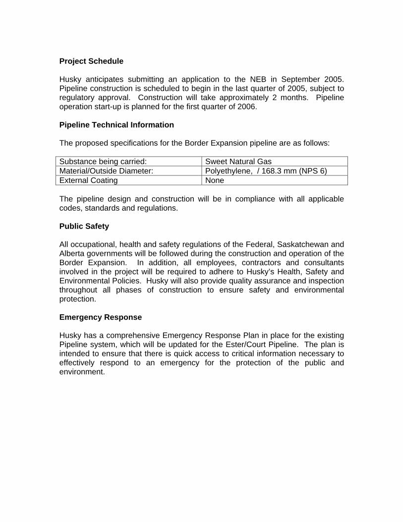
Project Schedule Husky anticipates submitting an application to the NEB in September 2005. Pipeline construction is scheduled to begin in the last quarter of 2005, subject to regulatory approval. Construction will take approximately 2 months. Pipeline operation start-up is planned for the first quarter of 2006. Pipeline Technical Information The proposed specifications for the Border Expansion pipeline are as follows: Substance being carried: Sweet Natural Gas Material/Outside Diameter: Polyethylene, / 168.3 mm (NPS 6) External Coating None The pipeline design and construction will be in compliance with all applicable codes, standards and regulations. Public Safety All occupational, health and safety regulations of the Federal, Saskatchewan and Alberta governments will be followed during the construction and operation of the Border Expansion. In addition, all employees, contractors and consultants involved in the project will be required to adhere to Husky’s Health, Safety and Environmental Policies. Husky will also provide quality assurance and inspection throughout all phases of construction to ensure safety and environmental protection. Emergency Response Husky has a comprehensive Emergency Response Plan in place for the existing Pipeline system, which will be updated for the Ester/Court Pipeline. The plan is intended to ensure that there is quick access to critical information necessary to effectively respond to an emergency for the protection of the public and environment.

Contacts Interested parties having any questions regarding the Ester/Court Pipeline may contact Husky at: Husky Oil Limited Box 6525, Station D 707 – 8th Avenue S.W. Calgary, Alberta T2P 3G7 Attention: Mr. Phil Fedoruk Name Department Telephone Fax Brent Nicholson Pipeline Operations (780) 753-6488 Ext. 28 (780) 753-4732 Brent Verner Land Department (403) 750-1711 (403) 750-1660 Adrian Strong Business Unit (403) 750-1825 (403) 750-1950 Phil Fedoruk Project Leader (403) 750-1447 (403) 750-1755 Husky’s 24-hour emergency phone number is (403) 262-2111. Husky is committed to conducting a comprehensive consultation program for the Ester/Court Pipeline. Husky will endeavour to address any concerns or information requests that may arise during the consultation program. The NEB Approval If you would like additional information about the NEB’s review and approval process, you may contact the Husky personnel listed above, or you may also contact the NEB directly at: Mr. Michael Mantha National Energy Board 444 – 7th Avenue S.W. Calgary, Alberta T2P a0X8 Phone: 1-800-899-1265 www.neb-one.gc.ca The NEB has prepared a filing manual that is available for viewing on the NEB web site. The filing manual contains information for viewing on the NEB web site.
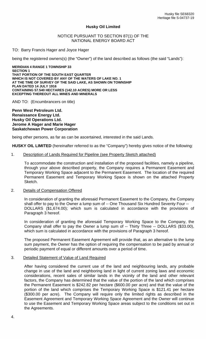
Husky file SE68320 Heritage file S-04737-19
Husky Oil Limited
NOTICE PURSUANT TO SECTION 87(1) OF THE
NATIONAL ENERGY BOARD ACT
TO: Barry Francis Hager and Joyce Hager
being the registered owners(s) (the “Owner”) of the land described as follows (the said “Lands”):
MERIDIAN 4 RANGE 1 TOWNSHIP 33 SECTION 1 THAT PORTION OF THE SOUTH EAST QUARTER WHICH IS NOT COVERED BY ANY OF THE WATERS OF LAKE NO. 1 AT THE TIME OF SURVEY OF THE SAID LAKE, AS SHOWN ON TOWNSHIP PLAN DATED 14 JULY 1916 CONTAINING 57.540 HECTARES (142.10 ACRES) MORE OR LESS EXCEPTING THEREOUT ALL MINES AND MINERALS AND TO: (Encumbrancers on title)
Penn West Petroleum Ltd. Renaissance Energy Ltd. Husky Oil Operations Ltd. Jerome A Hager and Marie Hager Saskatchewan Power Corporation being other persons, as far as can be ascertained, interested in the said Lands.
HUSKY OIL LIMITED (hereinafter referred to as the “Company”) hereby gives notice of the following:
1. Description of Lands Required for Pipeline (see Property Sketch attached)
To accommodate the construction and installation of the proposed facilities, namely a pipeline, through your above described property, the Company requires a Permanent Easement and Temporary Working Space adjacent to the Permanent Easement. The location of the required Permanent Easement and Temporary Working Space is shown on the attached Property Sketch.
2. Details of Compensation Offered
In consideration of granting the aforesaid Permanent Easement to the Company, the Company shall offer to pay to the Owner a lump sum of -- One Thousand Six Hundred Seventy Four -- DOLLARS ($1,674.00); which sum is calculated in accordance with the provisions of Paragraph 3 hereof.
In consideration of granting the aforesaid Temporary Working Space to the Company, the Company shall offer to pay the Owner a lump sum of -- Thirty Three -- DOLLARS ($33.00), which sum is calculated in accordance with the provisions of Paragraph 3 hereof.
The proposed Permanent Easement Agreement will provide that, as an alternative to the lump sum payment, the Owner has the option of requiring the compensation to be paid by annual or periodic payment of equal or different amounts over a period of time.
3. Detailed Statement of Value of Land Required
After having considered the current use of the land and neighbouring lands, any probable change in use of the land and neighboring land in light of current zoning laws and economic considerations, recent sales of similar lands in the vicinity of the land and other relevant factors, the Company has determined that the value of the portion of the land which comprises the Permanent Easement is $242.82 per hectare ($600.00 per acre) and that the value of the portion of the land which comprises the Temporary Working Space is $121.41 per hectare ($300.00 per acre). The Company will require only the limited rights as described in the Easement Agreement and Temporary Working Space Agreement and the Owner will continue to use the Easement and Temporary Working Space areas subject to the conditions set out in the Agreements.
4.

Description of Procedure for Approval of Detailed Route of Pipeline
Sections 34 through 39, inclusive, of the National Energy Board Act (the “Act”) establish a procedure for approval of the detailed route of a pipeline.
Those sections provide that after a pipeline company has submitted to the National Energy Board (the “Board”) a plan showing the proposed route of a pipeline, the company must serve on landowners and publish notices which describe the proposed detailed route of the pipeline and the location of the offices of the Board. Within thirty (30) days of service or last publication of such a notice, an owner or person who anticipates that his land may be adversely affected by the proposed detailed route may oppose the detailed route by filing with the Board a written statement setting forth the nature of his interest in the land and the grounds for his opposition.
Where a written statement of opposition has been filed within the time limited therefore, the Board must, subject to certain exceptions, forthwith order that a public hearing be conducted within the area in which the lands to which the written statement relates are situated with respect to any grounds of opposition set forth in such statement. At such hearing each person who properly filed a written statement will be allowed to make representations and the Board may allow any other interested person to make such representations as the Board deems proper.
Following such hearing the Board may either approve or refuse to approve the plan showing the proposed route of ~ the pipeline as filed by the pipeline company and in granting any approval the Board may impose such terms and conditions as it considers proper. The Board may not give its approval to a plan unless it has taken into account all written statements properly filed with it and all representations made to it at a public hearing in order to determine the best possible detailed route of the pipeline and the most appropriate methods and timing of constructing the pipeline.
In certain circumstances the procedure outlined above will not be applicable. Section 58 and subsection 45(3) of the Act empower the Board to exempt a pipeline company from certain of the provisions of the Act, including those provisions requiring the filing with the Board of a plan showing the proposed route of a pipeline. Exemption from this requirement would result in the above-described procedure for approval of the detailed route of a pipeline no longer being applicable. Husky intends to apply for such an exemption in respect of the proposed Esther Gas pipeline expansion which is the subject of this Easement. Consequently concerns, if any, regarding the routing of the pipeline and construction procedures should be communicated directly to the Board as part of the Section 58 approval process.
Reference is made to the sections of the Act referred to above for the complete text of the provisions relating the procedure for determination and approval of a pipeline route and the provisions which result in exemption from such procedures, and the foregoing description is subject to the express provisions thereof.
5. Description of Procedure Available for Negotiation and Arbitration of Compensation Payable
Sections 88 through 103, inclusive, of the Act establish a procedure for negotiation and arbitration in the event that an owner of lands and a pipeline company are unable to agree on any matter respecting the amount of compensation payable under the Act for the acquisition of lands or for damages suffered as a result of the operations of the pipeline company or on any issue related to such compensation.
Those sections provide, in effect, that if a pipeline company and an owner of lands have not agreed on any such issue either of them may serve notice of negotiation on the other of them and on the Minister (being the member of the Federal Cabinet designated to act as the Minster for the purposes of the Act) requesting that the matter be negotiated. Following service of such notice the Minister must appoint a negotiator who must meet with the parties and, without prejudice to any subsequent proceedings, proceed to negotiate a settlement of the matter. Within sixty days after commencing the negotiation proceedings, the negotiator must report to the Minister his success or failure and submit a copy of his report to both parties.

If either the owner of the lands or the pipeline company wishes to dispense with the negotiation proceedings or if the negotiation proceedings have not resulted in settlement of any compensation matter, either the pipeline company or the owner may serve notice of arbitration on the other of them and on the Minister requesting that the matter be determined by arbitration. Forthwith thereafter the Minister must, subject to certain exceptions, refer the matter to an Arbitration Committee consisting of not less than three members appointed by the Minister, none of whom will be a member, officer or employee of the Board. The Arbitration Committee must then fix a suitable time and place for a hearing in order to determine all compensation matters referred to in the notice and serve notice of the hearing on the parties. Following such hearing the Arbitration Committee will determine all compensation matters referred to it and in doing so must consider a number of factors as set out in section 97 of the Act.
Reference is made to the sections of the Act referred to above for the complete text of the provisions relating to negotiation and arbitration of compensation matters and the foregoing description is subject to the express provisions thereof.
6. Further Communications
This Notice is not an offer and does not obligate either the Owner or the Company to enter into an Agreement.
If you have any questions, please contact Husky Oil Limited, 707 – 8th Avenue S.W., Calgary, Alberta T2P 1H5. The address of the National Energy Board is 311 – 6th Avenue S.W., Calgary, Alberta T2P 3H2.
HUSKY OIL LIMITED By its Agent: Heritage Surface Solutions Ltd.
NATIONAL ENERGY BOARD ACT
ACKNOWLEDGEMENT OF RECEIPT (ALBERTA)
The undersigned, being registered owner or other person(s) having an interest in the lands referred to in the annexed Notice pursuant to Section 87(1) of the National Energy Board Act, hereby acknowledges receipt from HUSKY OIL LIMITED of a copy of the said Notice on the date and at the place shown opposite his or her signature.
Date Place Signature Witness
Calgary Penn West Petroleum Ltd. Per;
AFFIDAVIT OF SERVICE
I, of the City of Calgary in the Province of Alberta, Canada, make oath and say:
1. That I did on the day of , 2005 serve with a Notice from HUSKY OIL LIMITED, pursuant to Section 87(1) of the National Energy Board Act, a copy of which is annexed, by delivering such Notice to, and leaving same with
SWORN BEFORE ME at the of , in the Province of Alberta, this day of , 2005.
))))))
A COMMISSIONER FOR OATHS in and for the Province of Alberta
Land Agent’s Signature

NATIONAL ENERGY BOARD ACT
ACKNOWLEDGEMENT OF RECEIPT (ALBERTA)
The undersigned, being registered owner or other person(s) having an interest in the lands referred to in the annexed Notice pursuant to Section 87(1) of the National Energy Board Act, hereby acknowledges receipt from HUSKY OIL LIMITED of a copy of the said Notice on the date and at the place shown opposite his or her signature.
Date Place Signature Witness
Calgary Renaissance Energy Ltd. Per; Brent Verner
Calgary Husky Oil Operations Ltd. Per; Brent Verner
AFFIDAVIT OF SERVICE
I, of the City of Calgary in the Province of Alberta, Canada, make oath and say:
1. That I did on the day of , 2005 serve with a Notice from HUSKY OIL LIMITED, pursuant to Section 87(1) of the National Energy Board Act, a copy of which is annexed, by delivering such Notice to, and leaving same with
SWORN BEFORE ME at the of , in the Province of Alberta, this day of , 2005.
))))))
A COMMISSIONER FOR OATHS in and for the Province of Alberta
Land Agent’s Signature
NATIONAL ENERGY BOARD ACT
ACKNOWLEDGEMENT OF RECEIPT (ALBERTA)
The undersigned, being registered owner or other person(s) having an interest in the lands referred to in the annexed Notice pursuant to Section 87(1) of the National Energy Board Act, hereby acknowledges receipt from HUSKY OIL LIMITED of a copy of the said Notice on the date and at the place shown opposite his or her signature.
Date Place Signature Witness
Jerome A Hager
Marie Hager
AFFIDAVIT OF SERVICE
I, of the City of Calgary in the Province of Alberta, Canada, make oath and say:
1. That I did on the day of , 2005 serve with a Notice from HUSKY OIL LIMITED, pursuant to Section 87(1) of the National Energy Board Act, a copy of which is annexed, by delivering such Notice to, and leaving same with
SWORN BEFORE ME at the of , in the Province of Alberta, this day of , 2005.
))))))
A COMMISSIONER FOR OATHS in and for the Province of Alberta
Land Agent’s Signature
NATIONAL ENERGY BOARD ACT
ACKNOWLEDGEMENT OF RECEIPT (ALBERTA)
The undersigned, being registered owner or other person(s) having an interest in the lands referred to in the annexed Notice pursuant to Section 87(1) of the National Energy Board Act, hereby acknowledges receipt from HUSKY OIL LIMITED of a copy of the said Notice on the date and at the place shown opposite his or her signature.
Date Place Signature Witness
Barry Francis Hager
Joyce Hager
AFFIDAVIT OF SERVICE
I, of the City of Calgary in the Province of Alberta, Canada, make oath and say:
2. That I did on the day of , 2005 serve with a Notice from HUSKY OIL LIMITED, pursuant to Section 87(1) of the National Energy Board Act, a copy of which is annexed, by delivering such Notice to, and leaving same with
SWORN BEFORE ME at the of , in the Province of Alberta, this day of , 2005.
))))))
A COMMISSIONER FOR OATHS in and for the Province of Alberta
Land Agent’s Signature

Husky file SE68320 HUSKY OIL LIMITED
EASEMENT AGREEMENT
(ALBERTA)
I/We, Barry Francis Hager and Joyce Hager, as joint tenants, (hereinafter referred to as the “Owner”) being the registered owner(s) of an estate in fee simple in all that certain tract of land, namely: MERIDIAN 4 RANGE 1 TOWNSHIP 33 SECTION 1 THAT PORTION OF THE SOUTH EAST QUARTER WHICH IS NOT COVERED BY ANY OF THE WATERS OF LAKE NO. 1 AT THE TIME OF SURVEY OF THE SAID LAKE, AS SHOWN ON TOWNSHIP PLAN DATED 14 JULY 1916 CONTAINING 57.540 HECTARES (142.10 ACRES) MORE OR LESS EXCEPTING THEREOUT ALL MINES AND MINERALS and described in Certificate of Title No. 041 302 965 registered in the Land Titles Office for the North Alberta Land Registration District (hereinafter referred to as the said “Lands”) DO HEREBY, in consideration of the sum of ---TEN--- ($---10.00---) DOLLARS paid to the Owner (receipt of which is hereby acknowledged) by HUSKY OIL LIMITED. (hereinafter referred to as the “Company”) and in consideration of the covenants herein contained, GRANT, CONVEY, TRANSFER AND SET OVER to and unto the Company, for itself, its employees, agents, contractors, subcontractors, successors and assigns, the right, license, liberty, privilege and easement across, over, under or on, and to clear and to use that portion of the said Lands as approximated on the property sketch, a copy of which is attached hereto (hereinafter referred to as the “Easement Lands”), to survey, construct, operate, maintain, inspect, patrol (including aerial patrol), alter, remove, replace, reconstruct and repair one or more pipelines (hereinafter referred to as the “Pipeline”), subject to Clause 4 herein, and other facilities appurtenant or incidental thereto (the Pipeline together with other facilities appurtenant or incidental thereto being hereinafter collectively referred to as the “Works”), for the transportation, storage and handling of liquid and gaseous hydrocarbons and products thereof, together with the right of access to and from the Easement Lands across the remainder of the said Lands by all necessary means and with all necessary personnel and equipment in emergency situations only. The aforesaid rights, licenses, liberties, privileges and easements are herein granted for so long hereafter as the Company may desire to exercise same on the following terms, stipulations and conditions which are hereby mutually covenanted and agreed to by and between the Owner and the Company:
1. PLAN OF EASEMENT The Company shall, upon the completion of a legal survey plan, deposit for registration at the Land Titles Office a plan of survey limiting the Easement Lands to a strip of land being generally twenty-nine metres in width within the said Lands which easement shall be substantially in the location as shown on the attached property sketch. Following registration of such plan of survey the Company shall forward to the Owner at the address set forth in Clause 18 hereof an extract from the plan of survey showing the actual location of the Easement Lands on the said Lands.
2. RESTRICTION BY PARTIAL WITHDRAWAL AND DISCHARGE The Company, having delivered or mailed to the Owner the extract from the plan of survey, shall as soon as it is practicable to do so, cause to be registered in the Land Titles Office, a document restricting the Easement Lands to that area shown upon the plan of survey, but notwithstanding the registration of such document the Company shall continue to be entitled to enjoy the right of emergency access as set out in the granting provision of this Agreement.
3. PAYMENT FOR EASEMENT The Company shall pay to the Owner compensation for the grant of easement as follows: (a) one lump sum of /100 Dollars
($ ) (hereinafter referred to as the “Lump Sum Payment”), which sum includes compensation for the temporary workspace as identified on the attached plan.
(b) annual or periodic payments of equal or different amounts over a period of time as set forth in Schedule 1 attached
hereto and forming part hereof. In the event the Owner elects to be compensated by Lump Sum, such Lump Sum Payment shall be made before construction of the Works is commenced on the said Lands. In the event that this payment has not been made before ______________ ,2006, then this Agreement shall terminate and be at an end for all purposes and the Company shall forthwith execute and register such documents as may be necessary to discharge this Agreement from the Certificate of Title for the said Lands and shall notify the Owner of the registration of the discharge.
4. ADDITIONAL PIPELINES The Company intends to install one (1) Pipeline in the first trench to be excavated on the Easement Lands. Each time the Easement Lands are trenched thereafter for installation of an additional Pipeline or Pipelines, the Company shall negotiate a new agreement and pay to the Owner a sum calculated at a rate per hectare to be agreed between the Owner and the Company for that portion of the Easement Lands used for the additional Pipeline or Pipelines.
5. ABOVE GROUND INSTALLATIONS If at any time the Company shall require the Easement Lands for installation of Works to be located above ground (other than pipeline warning markers installed at fence lines) the Company shall consult with the Owner as to the appropriate location of such Works and shall locate such Works, insofar as may be practicable to do so, in such a fashion as to provide a minimum of inconvenience to the Owner. Upon furnishing to the Owner a plan of the intended location and negotiating an Above Ground Installation Agreement, the Company shall have the right to fence and to use such portions of the Easement Lands as may, in its opinion, be required.

6. DAMAGES The Company shall compensate the Owner for all damage suffered by him as a result of the construction or operations of the Company, its employees, agents, contractors and subcontractors.
7. INDEMNIFICATION The Company shall indemnify and save harmless the Owner from any and all liabilities, damages, costs, claims, suits or actions caused by or resulting from the use by the Company of the said Lands other than liabilities, damages, costs, claims, suits or actions caused by the wilful misconduct or gross negligence of the Owner, his employees, agents or contractors.
8. OWNER’S USE OF THE EASEMENT LANDS The Owner shall have the right to use and enjoy the Easement Lands for any purpose except for any use which would interfere with the rights granted in this Agreement to the Company, and the Owner shall not without the prior written consent of the Company, which consent shall not be unreasonably withheld, excavate, drill, install, erect or permit to be excavated, drilled, installed or erected on, in or under the Easement Lands any pit, well, pipeline, foundation, pavement, pile of material, building or other structure or installation or do or permit to be done any mining, quarrying or other work or activity of any similar nature on, in or under the Easement Lands.
9. COMPENSATION FOR ADDITIONAL COSTS The Company shall compensate the Owner for reasonable additional costs incurred by the Owner in connection with the excavation, drilling, installation, erection, repair or construction for any permitted agricultural or related use on, in or under the Easement Lands which are attributable to the existence of the Company’s Works.
10. RELEASE OF OWNER FROM CLAIMS BY THE COMPANY The Owner shall not be liable to the Company for any damage caused to the Works, which occurs as a result of the permitted use and occupation of the Easement Lands by the Owner, with the exception of all damage caused by the wilful misconduct or gross negligence of the Owner, his employees, agents or contractors.
11. QUIET ENJOYMENT The Company upon performing and observing the covenants and conditions on its part to be performed and observed shall and may peaceably hold and enjoy the rights hereby granted without hindrance, molestation or interruption on the part of the Owner or any person claiming by, through or in trust for the Owner.
12. TAXES The Company shall pay all rates and taxes that may be assessed and levied from time to time against the interest of the Company by reason of its installation of the Works on the Easement Lands or in connection with its operations thereon.
13. ASSIGNMENT This Agreement is a covenant running with the said Lands and the provisions of this Agreement including all covenants and conditions herein contained shall extend to, be binding upon, and enure to the benefit of, the heirs, executors, administrators, successors and assigns of the Owners and the Company.
14. OWNERSHIP OF COMPANY PROPERTY Notwithstanding any rule of law or equity, all Works placed in, on or under the Easement Lands by the Company shall, at all times, until surrendered, remain personal property and the property of the Company even though attached to the said Lands and may at any time or from time to time be removed in whole or in part by the Company.
15. ENVIRONMENTAL REPRESENTATIONS AND WARRANTIES
(a) The Owner represents and warrants to the Company that, to the best of the Owner’s knowledge, no hazardous or toxic materials, substances, pollutants, contaminants or wastes have been released into the environment, or deposited, discharged, placed or disposed of at, on, under or near the Easement Lands.
(b) The Owner covenants to the Company that, if the Owner becomes aware of or is informed of any
hazardous or toxic materials, substances, pollutants, contaminants or wastes which were, may have been or are being released into the environment, or deposited, discharged, placed or disposed of at, on, under or near the Easement Lands, the Owner shall forthwith give verbal notice to the Company (collect) at (403)266-4464, or at such other number as the Owner may be advised, giving details of the above.
16. RECLAMATION Upon completion of construction, the Company shall reclaim any of the said Lands that have been disturbed in accordance with applicable environmental laws.
17. SURRENDER The Company may at any time and from time to time surrender by appropriate instrument, the rights acquired by it hereunder in all or in part of the said Lands and the Company may, but shall not be obligated to, remove all or any Works which the Company may have installed or placed in, on or under the said Lands, or the part thereof being surrendered. The Company agrees to remove and discharge any instrument or encumbrance registered against any Certificate of Title insofar as it relates to its interest in the said Lands being surrendered.

18. NOTICES Any notice or payment to be made hereunder by one party to the other may be personally delivered by that party or its agent or may be mailed postage prepaid to the other party at the address immediately following or at such other address as the Owner or the Company may respectively from time to time designate in writing and any notice or payment sent by mail shall be deemed to have been given to and received by the addressee seven (7) days after mailing thereof: OWNER: COMPANY: 220 Lampard Crescent HUSKY OIL LIMITED Red Deer, Alberta 707 – 8th Avenue S.W. T4R 2W5 Calgary, Alberta T2P 1H5
19. INTERPRETATION In this Agreement,
(a) wherever the singular or masculine is used, the same shall be construed as being plural or feminine or a body corporate, where the context might reasonably require, and
(b) the titles or headings are inserted for convenience of reference only and shall not affect the interpretation
or construction of this Agreement.
20. METHOD OF COMPENSATION The Owner confirms having the option of requiring the compensation for the rights herein granted to be made by one lump sum payment or by annual or periodic payments of equal or different amounts over a period of time and that the Owner has selected the method of compensation hereinbefore set out. The Owner and the Company further confirm that if the Owner has selected annual or other periodic payments, the amount of such compensation payable by the Company, shall be reviewed every five (5) years if the period of compensation extends beyond five (5) years.
21. ARBITRATION If the amount for compensation for the acquisition of the Easement Lands, damages, and/or above-ground structures payable cannot be agreed upon by the Owner and the Company, it shall be determined pursuant to the National Energy Board Act (the “Act”).
22. SECTION 87(1) NOTICE The Owner acknowledges receipt, prior to the entering into of this Agreement, of a notice given pursuant to Section 87(1) of the Act, setting out or accompanied by:
(a) a description of the portion of the said lands of the Owner required by the Company for a section or part of the Pipeline or Works;
(b) details of the compensation offered by the Company for such lands required; (c) a detailed statement made by the Company of the value of such lands required in respect of which
compensation was offered; (d) a description of the procedure for approval of the detailed route of the Company’s Pipeline; and (e) a description of the procedure available for negotiation and arbitration under Part V of the Act in the event
that the Owner and the Company are unable to agree on any matter respecting the compensation payable.
IN WITNESS WHEREOF the Owner, and the Company have executed and delivered these presents this _______ day of
_____________________________, A.D. 2005.
SIGNED AND DELIVERED in the presence of: ______________________________________________ Witness ______________________________________________ Witness
) ) ) ) ) ) ) ) ) ) )
_____________________________________________ Barry Francis Hager _____________________________________________ Joyce Hager
HUSKY OIL LIMITED Per:__________________________________________
1126012_1

AFFIDAVIT OF EXECUTION
CANADA I, , PROVINCE OF ALBERTA of the City of Calgary, in the Province of Alberta, TO WIT: Landman, make oath and say: 1. That I was personally present and did see Barry Francis Hager and Joyce Hager named in the within
instrument, who is (are) personally known to me to be the person(s) named therein, duly sign and execute the same for the purpose named therein.
2. That the same was executed at/near in the Province of Alberta,
and that I am the subscribing witness thereto.
3. That I know the said Barry Francis Hager and Joyce Hager and he/she is (they are) my belief of the full age of eighteen years.
SWORN before me at the City of Calgary, ) in the Province of Alberta this day ) of , A.D. 2005. ) A Commissioner for Oaths in and for the Province of Alberta
Husky Oil Operations Limited June 2006 Esther Court Pipeline
Appendix 8
Construction Schedule

ID Task Name Duration Start1 Husky Esther Court Pipeline 30 days Tue 8/15/06
2 NEB Approval (Assumed Date) 0 days Tue 8/15/06
3 Constructon notification 14 days Tue 8/15/06
4 Restake the RoW for Construction 2 days Tue 8/29/06
5 Stripping (if required) 2 days Thu 8/31/06
6 Plowing 4 days Sat 9/2/06
7 Crossings Installation 3 days Wed 9/6/06
8 Risers Installation 2 days Wed 9/6/06
9 Testing 1 day Sat 9/9/06
10 End Facility Installation 5 days Fri 9/8/06
11 Final Tie-ins 1 day Wed 9/13/06
8/15
S M T W T F S S M T W T F S S M T W T F S S M T W T F S S M T W T FAug 13, '06 Aug 20, '06 Aug 27, '06 Sep 3, '06 Sep 10, '06
Task
Split
Progress
Milestone
Summary
Rolled Up Task
Rolled Up Split
Rolled Up Milestone
Rolled Up Progress
External Tasks
Project Summary
Page 1
Project: Husky Esther Court PipelineDate: Mon 5/15/06

Husky Oil Operations Limited June 2006 Esther Court Pipeline
Appendix 9
HDPE TECHNICAL BROCHURE

ENGINEERED FOR GAS GATHERING PIPING SYSTEMS
PLASTIC MANUFACTURES “SINCE 1953”

POLYTUBES Gas Gathering Piping Products
Polytubes Technical Bulletin 2004 Page 2
“GAS /OIL”
(Gas Gathering and Fuel Gas Applications)
• CONTINUOUS POLYETHYLENE LENGTH “REELS” UP TO 1200 M
• PLOWING (PLANTING) UP TO 6” AT
TEMPERATURES AS LOW AS -20°C WITH SAVING UP TO 50% COMPARED TO STEEL
• EXCELLENT CHEMICAL RESISTANCE • CERTIFIED PE-3408 HDPE RESINS ARE USED • SAVINGS OVER STEEL AS HIGH AS 50% • RESISTANCE TO ELECTROLYTIC CORROSION • HIGHER FLOW RATES VERSUS STEEL • PE-3408 PIPE CAN BE BUTT FUSED AT SITE
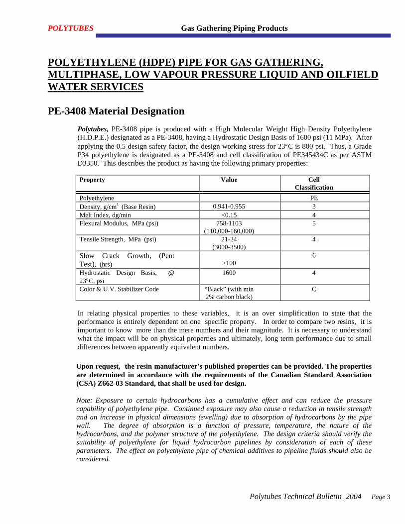
POLYTUBES Gas Gathering Piping Products
Polytubes Technical Bulletin 2004 Page 3
POLYETHYLENE (HDPE) PIPE FOR GAS GATHERING, MULTIPHASE, LOW VAPOUR PRESSURE LIQUID AND OILFIELD WATER SERVICES PE-3408 Material Designation
Polytubes, PE-3408 pipe is produced with a High Molecular Weight High Density Polyethylene (H.D.P.E.) designated as a PE-3408, having a Hydrostatic Design Basis of 1600 psi (11 MPa). After applying the 0.5 design safety factor, the design working stress for 23°C is 800 psi. Thus, a Grade P34 polyethylene is designated as a PE-3408 and cell classification of PE345434C as per ASTM D3350. This describes the product as having the following primary properties: Property Value Cell
Classification Polyethylene PE Density, g/cm3 (Base Resin) 0.941-0.955 3 Melt Index, dg/min <0.15 4 Flexural Modulus, MPa (psi) 758-1103
(110,000-160,000) 5
Tensile Strength, MPa (psi) 21-24 (3000-3500)
4
Slow Crack Growth, (Pent Test), (hrs)
>100
6
Hydrostatic Design Basis, @ 23°C, psi
1600 4
Color & U.V. Stabilizer Code “Black” (with min 2% carbon black)
C
In relating physical properties to these variables, it is an over simplification to state that the performance is entirely dependent on one specific property. In order to compare two resins, it is important to know more than the mere numbers and their magnitude. It is necessary to understand what the impact will be on physical properties and ultimately, long term performance due to small differences between apparently equivalent numbers. Upon request, the resin manufacturer's published properties can be provided. The properties are determined in accordance with the requirements of the Canadian Standard Association (CSA) Z662-03 Standard, that shall be used for design. Note: Exposure to certain hydrocarbons has a cumulative effect and can reduce the pressure capability of polyethylene pipe. Continued exposure may also cause a reduction in tensile strength and an increase in physical dimensions (swelling) due to absorption of hydrocarbons by the pipe wall. The degree of absorption is a function of pressure, temperature, the nature of the hydrocarbons, and the polymer structure of the polyethylene. The design criteria should verify the suitability of polyethylene for liquid hydrocarbon pipelines by consideration of each of these parameters. The effect on polyethylene pipe of chemical additives to pipeline fluids should also be considered.
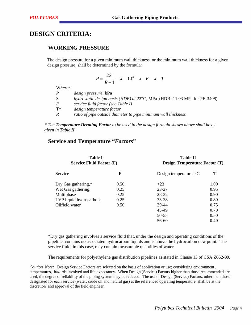
POLYTUBES Gas Gathering Piping Products
Polytubes Technical Bulletin 2004 Page 4
DESIGN CRITERIA:
WORKING PRESSURE
The design pressure for a given minimum wall thickness, or the minimum wall thickness for a given design pressure, shall be determined by the formula:
P SR
x x F x T=−
21
103
Where: P design pressure, kPa S hydrostatic design basis (HDB) at 23°C, MPa (HDB=11.03 MPa for PE-3408) F service fluid factor (see Table I) T* design temperature factor R ratio of pipe outside diameter to pipe minimum wall thickness
* The Temperature Derating Factor to be used in the design formula shown above shall be as given in Table II
Service and Temperature “Factors”
Table I Table II Service Fluid Factor (F) Design Temperature Factor (T) Service F Design temperature, °C T Dry Gas gathering,* 0.50 <23 1.00 Wet Gas gathering, 0.25 23-27 0.95 Multiphase 0.25 28-32 0.90 LVP liquid hydrocarbons 0.25 33-38 0.80 Oilfield water 0.50 39-44 0.75 45-49 0.70 50-55 0.50 56-60 0.40
*Dry gas gathering involves a service fluid that, under the design and operating conditions of the pipeline, contains no associated hydrocarbon liquids and is above the hydrocarbon dew point. The service fluid, in this case, may contain measurable quantities of water The requirements for polyethylene gas distribution pipelines as stated in Clause 13 of CSA Z662-99.
Caution Note: Design Service Factors are selected on the basis of application or use; considering environment , temperatures, hazards involved and life expectancy. When Design (Service) Factors higher than those recommended are used, the degree of reliability of the piping system may be reduced. The use of Design (Service) Factors, other than those designated for each service (water, crude oil and natural gas) at the referenced operating temperature, shall be at the discretion and approval of the field engineer.
POLYTUBES Gas Gathering Piping Products
Polytubes Technical Bulletin 2004 Page 5
DESIGN CONSIDERATIONS:
CHEMICAL RESISTANCE
Polytubes PE-3408 polyethylene piping material possesses a high resistance to attack from a wide range of chemicals and for all practical purposes; HD-Polyethylene is chemically inert at normal service temperatures. The fact that HD-Polyethylene is virtually chemical inert at 23°C, allows Polytubes pipe to be used in many applications where traditional materials would be considered unsuitable. It can be stated that, at 23°C Polytubes, PE-3408 pipe can be used when exposed to many different acids, bases and inorganic salts at 100% concentration with out any deteriorating effects. Polyethylene does not corrode or rot, become pitted or interact, either chemically or electrically, with the surrounding soil despite its acidity, alkalinity or moisture content. It does not support the growth of algae, bacteria or fungi and resists marine biological attack. Certain chemicals do have an effect on the polyethylene. The chemical attack on polyethylene can be classified in two ways. ONE is solubility or a swelling phenomena of the polyethylene, that of which, if the chemical is removed the polyethylene will regain its original properties and shape. The SECOND is a more severe detrimental attack, where the physical characteristics of the polyethylene have been changed. Oxidizers are the only group of chemicals that are capable of chemically degrading Polytubes pipe. The following oxidizers are considered unsuitable for long term exposure/contact with Polytubes pipe: Nitric acid, fuming Sulphuric acid, fuming (oleum) Wet chlorine gas Liquid bromine Dry gaseous hydrocarbons have no adverse effect on expected service life. Liquid hydrocarbons act like a plasticizer and can be absorbed to varying degrees in the pipe wall (causing softening) and can reduce hydrostatic strength, but they do not degrade the material. Upon evaporation of the hydrocarbon, the pipe will regain its original physical properties. When in continuous contact with hydrocarbons, the pipe's hydrostatic strength or allowable operating pressure must be derated. The aggressive nature of the hydrocarbon can be classified as either a strong or weak plasticizer. Shown below are examples of the different types of plasticizer. If you are handling any of the strong plasticizer at high concentrations listed below, consult your Polytubes Representative for assistance in designing your piping system. The weak plasticizers only have minor plasticizing effects and the derating factors shown in Table I (SF=0.25) can be used.
POLYTUBES Gas Gathering Piping Products
Polytubes Technical Bulletin 2004 Page 6
Plasticizers:
I) STRONG PLASTICIZERS Aromatic hydrocarbons e. g. benzene and toluene Phenolics e. g. phenol and resorcinol Chlorinated hydrocarbons e. g. carbon tetrachloride Fats and oils e. g. liquid shortening, lube oils, vegetable oils.
(II) WEAK PLASTICIZERS
Lighter hydrocarbons (liquid) e.g. natural and manufactured gasoline Crude oils
Life Expectancy
The hydrostatic design basis for Polytubes pipe is based on extensive hydrostatic testing data evaluated by standardized industry methods. Life expectancy is estimated conservatively to be in excess of 50 years for transporting water at ambient temperature (73.4°F). Internal and external environmental conditions for each application may alter the expected life or change the recommended design basis to achieve the same life expectancy.
Joining
In a polyethylene installation, it is usually necessary to join additional lengths of pipe or attach fittings such as tees, saddles, valves or caps. Such joints may involve different grades and sizes of PE or different materials altogether. In all cases, safety and the qualification requirements of the responsible regulatory authority should prevail. Cleanliness of the components to be joined is absolutely essential to ensure proper joining. Other considerations when joining PE pipe and fittings include:
• Weather - ambient temperature, wind speed and direction, precipitation • Machine and tool condition - heating irons, alignment jigs • Specific material properties - melt, density • Joining technique
When both the pipe and fittings are made from polyethylene, they may be joined using mechanical (compression, stab) fittings or, preferably, heat fusion. The heat fusion method of joining is used for connecting lengths of polyethylene pipe and for attaching saddles, tees, stub-ends and other fittings. Should the materials be dissimilar, then compression or transition ( bell, flange, pre-assembled) fittings must be used..

POLYTUBES PE-3408 High Density Polyethylene (HDPE) PIPE For Gas Gathering, Multiphase, Low Vapour Pressure Liquid and Oilfield Water Services
“METRIC” PIPE DIMENSIONS AND OPERATING CONDITIONS
DIAMETER INCHES
Average Outside
Diameter
Standard Dimension
Ratio
Nominal Wall
Thickness
Nominal Internal Diameter
Average Pipe
Weight
23°C Continuos Operating Pressure
Burst Pressure
*Dry Gas Wet Gas O.E. OIL Water (mm) (SDR) (mm) (mm) (lb/m) (kPa) (kPa) (kPa) (kPa) (kPa) (kPa)
60.3 21 2.87 54.56 1.15 551 276 276 276 551 2205 60.3 17 3.55 53.21 1.41 689 345 345 345 689 2756 60.3 13.5 4.47 51.37 1.74 882 441 441 441 882 3528 60.3 11 5.48 49.34 2.10 1102 551 551 551 1102 4410 60.3 9 6.70 46.90 2.50 1378 689 689 689 1378 5512 60.3 7.3 8.26 43.78 2.99 1750 875 875 875 1750 6999 60.3 6.3 9.57 41.16 3.37 2080 1040 1040 1040 2080 8320
2”
60.3 5 12.06 36.18 4.02 2756 1378 1378 1378 2756 11024
73.0 21 3.48 66.05 1.69 551 276 276 276 551 2205 73.0 17 4.29 64.41 2.06 689 345 345 345 689 2756 73.0 13.5 5.41 62.19 2.55 882 441 441 441 882 3528 73.0 11 6.64 59.73 3.07 1102 551 551 551 1102 4410 73.0 9 8.11 56.78 3.67 1378 689 689 689 1378 5512 73.0 7.3 10.00 53.00 4.38 1750 875 875 875 1750 6999 73.0 6.3 11.59 49.83 4.94 2080 1040 1040 1040 2080 8320
2 ½”
73.0 5 14.60 43.80 5.90 2756 1378 1378 1378 2756 11024
88.9 21 4.23 80.43 2.51 551 276 276 276 551 2205 88.9 17 5.23 78.44 3.06 689 345 345 345 689 2756 88.9 13.5 6.59 75.73 3.79 882 441 441 441 882 3528 88.9 11 8.08 72.74 4.56 1102 551 551 551 1102 4410 88.9 9 9.88 69.14 5.44 1378 689 689 689 1378 5512 88.9 7.3 12.18 64.54 6.50 1750 875 875 875 1750 6999 88.9 6.3 14.11 60.68 7.33 2080 1040 1040 1040 2080 8320
3”
88.9 5 17.78 53.34 8.75 2756 1378 1378 1378 2756 11024
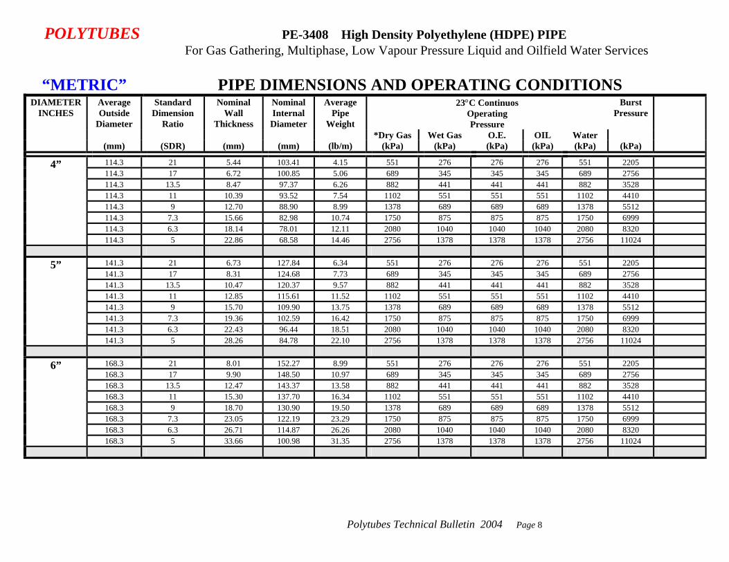
Polytubes Technical Bulletin 2004 Page 8
POLYTUBES PE-3408 High Density Polyethylene (HDPE) PIPE For Gas Gathering, Multiphase, Low Vapour Pressure Liquid and Oilfield Water Services
“METRIC” PIPE DIMENSIONS AND OPERATING CONDITIONS DIAMETER
INCHES Average Outside
Diameter
Standard Dimension
Ratio
Nominal Wall
Thickness
Nominal Internal Diameter
Average Pipe
Weight
23°C Continuos Operating Pressure
Burst Pressure
*Dry Gas Wet Gas O.E. OIL Water (mm) (SDR) (mm) (mm) (lb/m) (kPa) (kPa) (kPa) (kPa) (kPa) (kPa)
114.3 21 5.44 103.41 4.15 551 276 276 276 551 2205 114.3 17 6.72 100.85 5.06 689 345 345 345 689 2756 114.3 13.5 8.47 97.37 6.26 882 441 441 441 882 3528 114.3 11 10.39 93.52 7.54 1102 551 551 551 1102 4410 114.3 9 12.70 88.90 8.99 1378 689 689 689 1378 5512 114.3 7.3 15.66 82.98 10.74 1750 875 875 875 1750 6999 114.3 6.3 18.14 78.01 12.11 2080 1040 1040 1040 2080 8320
4”
114.3 5 22.86 68.58 14.46 2756 1378 1378 1378 2756 11024
141.3 21 6.73 127.84 6.34 551 276 276 276 551 2205 141.3 17 8.31 124.68 7.73 689 345 345 345 689 2756 141.3 13.5 10.47 120.37 9.57 882 441 441 441 882 3528 141.3 11 12.85 115.61 11.52 1102 551 551 551 1102 4410 141.3 9 15.70 109.90 13.75 1378 689 689 689 1378 5512 141.3 7.3 19.36 102.59 16.42 1750 875 875 875 1750 6999 141.3 6.3 22.43 96.44 18.51 2080 1040 1040 1040 2080 8320
5”
141.3 5 28.26 84.78 22.10 2756 1378 1378 1378 2756 11024
168.3 21 8.01 152.27 8.99 551 276 276 276 551 2205 168.3 17 9.90 148.50 10.97 689 345 345 345 689 2756 168.3 13.5 12.47 143.37 13.58 882 441 441 441 882 3528 168.3 11 15.30 137.70 16.34 1102 551 551 551 1102 4410 168.3 9 18.70 130.90 19.50 1378 689 689 689 1378 5512 168.3 7.3 23.05 122.19 23.29 1750 875 875 875 1750 6999 168.3 6.3 26.71 114.87 26.26 2080 1040 1040 1040 2080 8320
6”
168.3 5 33.66 100.98 31.35 2756 1378 1378 1378 2756 11024

Polytubes Technical Bulletin 2004 Page 9
POLYTUBES PE-3408 High Density Polyethylene (HDPE) PIPE For Gas Gathering, Multiphase, Low Vapour Pressure Liquid and Oilfield Water Services
“METRIC” PIPE DIMENSIONS AND OPERATING CONDITIONS DIAMETER
INCHES Average Outside
Diameter
Standard Dimension
Ratio
Nominal Wall
Thickness
Nominal Internal Diameter
Average Pipe
Weight
23°C Continuos Operating Pressure
Burst Pressure
*Dry Gas Wet Gas O.E. OIL Water (mm) (SDR) (mm) (mm) (lb/m) (kPa) (kPa) (kPa) (kPa) (kPa) (kPa)
219.1 21 10.43 198.23 15.24 551 276 276 276 551 2205 219.1 17 12.89 193.32 18.60 689 345 345 345 689 2756 219.1 13.5 16.23 186.64 23.01 882 441 441 441 882 3528 219.1 11 19.92 179.26 27.70 1102 551 551 551 1102 4410 219.1 9 24.34 170.41 33.05 1378 689 689 689 1378 5512 219.1 7.3 30.01 159.07 39.48 1750 875 875 875 1750 6999
8”
219.1 6.3 34.78 149.54 44.51 2080 1040 1040 1040 2080 8320
273.1 21 13.00 247.09 23.69 551 276 276 276 551 2205 273.1 17 16.06 240.97 28.89 689 345 345 345 689 2756 273.1 13.5 20.23 232.64 35.76 882 441 441 441 882 3528 273.1 11 24.83 223.45 43.03 1102 551 551 551 1102 4410 273.1 9 30.34 212.41 51.35 1378 689 689 689 1378 5512
10”
273.1 7.3 37.41 198.28 61.34 1750 875 875 875 1750 6999
323.9 21 15.42 293.05 33.32 551 276 276 276 551 2205 323.9 17 19.05 285.79 40.64 689 345 345 345 689 2756 323.9 13.5 23.99 275.91 50.29 882 441 441 441 882 3528 323.9 11 29.45 265.01 60.53 1102 551 551 551 1102 4410 323.9 9 35.99 251.92 72.23 1378 689 689 689 1378 5512
12”
323.9 7.3 44.37 235.16 86.28 1750 875 875 875 1750 6999
355.6 21 16.93 321.73 40.16 551 276 276 276 551 2205 355.6 17 20.92 313.76 48.98 689 345 345 345 689 2756 355.6 13.5 26.34 302.92 60.62 882 441 441 441 882 3528 355.6 11 32.33 290.95 72.96 1102 551 551 551 1102 4410
14”
355.6 9 39.51 276.58 87.06 1378 689 689 689 1378 5512
SPECIAL DIMENSIONS NOT LISTED ARE AVAILABLE UPON REQUEST “Continuos Operating Pressure” based on 50 year life at a 2:1 safety factor. “Burst Pressure” based on 2 minute burst pressure with no safety factor. *The requirements for polyethylene dry gas distribution pipelines as stated in Clause 13 of CSA Z662-99. **Reels available upon special request.
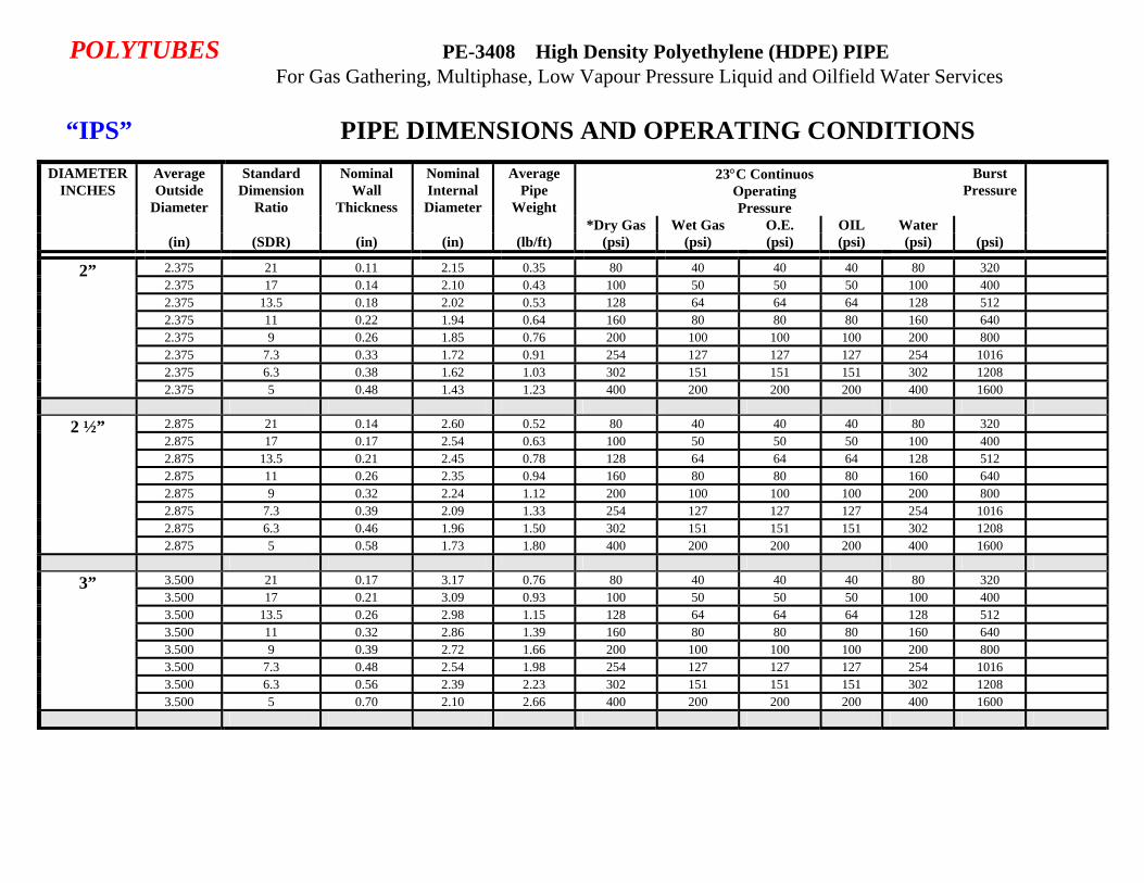
POLYTUBES PE-3408 High Density Polyethylene (HDPE) PIPE For Gas Gathering, Multiphase, Low Vapour Pressure Liquid and Oilfield Water Services
“IPS” PIPE DIMENSIONS AND OPERATING CONDITIONS
DIAMETER INCHES
Average Outside
Diameter
Standard Dimension
Ratio
Nominal Wall
Thickness
Nominal Internal Diameter
Average Pipe
Weight
23°C Continuos Operating Pressure
Burst Pressure
*Dry Gas Wet Gas O.E. OIL Water (in) (SDR) (in) (in) (lb/ft) (psi) (psi) (psi) (psi) (psi) (psi)
2.375 21 0.11 2.15 0.35 80 40 40 40 80 320 2.375 17 0.14 2.10 0.43 100 50 50 50 100 400 2.375 13.5 0.18 2.02 0.53 128 64 64 64 128 512 2.375 11 0.22 1.94 0.64 160 80 80 80 160 640 2.375 9 0.26 1.85 0.76 200 100 100 100 200 800 2.375 7.3 0.33 1.72 0.91 254 127 127 127 254 1016 2.375 6.3 0.38 1.62 1.03 302 151 151 151 302 1208
2”
2.375 5 0.48 1.43 1.23 400 200 200 200 400 1600
2.875 21 0.14 2.60 0.52 80 40 40 40 80 320 2.875 17 0.17 2.54 0.63 100 50 50 50 100 400 2.875 13.5 0.21 2.45 0.78 128 64 64 64 128 512 2.875 11 0.26 2.35 0.94 160 80 80 80 160 640 2.875 9 0.32 2.24 1.12 200 100 100 100 200 800 2.875 7.3 0.39 2.09 1.33 254 127 127 127 254 1016 2.875 6.3 0.46 1.96 1.50 302 151 151 151 302 1208
2 ½”
2.875 5 0.58 1.73 1.80 400 200 200 200 400 1600
3.500 21 0.17 3.17 0.76 80 40 40 40 80 320 3.500 17 0.21 3.09 0.93 100 50 50 50 100 400 3.500 13.5 0.26 2.98 1.15 128 64 64 64 128 512 3.500 11 0.32 2.86 1.39 160 80 80 80 160 640 3.500 9 0.39 2.72 1.66 200 100 100 100 200 800 3.500 7.3 0.48 2.54 1.98 254 127 127 127 254 1016 3.500 6.3 0.56 2.39 2.23 302 151 151 151 302 1208
3”
3.500 5 0.70 2.10 2.66 400 200 200 200 400 1600
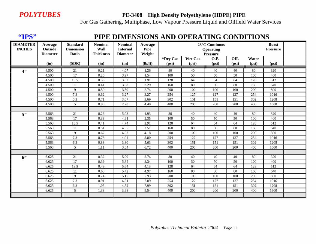
Polytubes Technical Bulletin 2004 Page 11
POLYTUBES PE-3408 High Density Polyethylene (HDPE) PIPE For Gas Gathering, Multiphase, Low Vapour Pressure Liquid and Oilfield Water Services
“IPS” PIPE DIMENSIONS AND OPERATING CONDITIONS
DIAMETER INCHES
Average Outside
Diameter
Standard Dimension
Ratio
Nominal Wall
Thickness
Nominal Internal Diameter
Average Pipe
Weight
23°C Continuos Operating Pressure
Burst Pressure
*Dry Gas Wet Gas O.E. OIL Water (in) (SDR) (in) (in) (lb/ft) (psi) (psi) (psi) (psi) (psi) (psi)
4.500 21 0.21 4.07 1.26 80 40 40 40 80 320 4.500 17 0.26 3.97 1.54 100 50 50 50 100 400 4.500 13.5 0.33 3.83 1.91 128 64 64 64 128 512 4.500 11 0.41 3.68 2.29 160 80 80 80 160 640 4.500 9 0.50 3.50 2.74 200 100 100 100 200 800 4.500 7.3 0.62 3.27 3.27 254 127 127 127 254 1016 4.500 6.3 0.71 3.07 3.69 302 151 151 151 302 1208
4”
4.500 5 0.90 2.70 4.40 400 200 200 200 400 1600
5.563 21 0.26 5.03 1.93 80 40 40 40 80 320 5.563 17 0.33 4.91 2.35 100 50 50 50 100 400 5.563 13.5 0.41 4.74 2.91 128 64 64 64 128 512 5.563 11 0.51 4.55 3.51 160 80 80 80 160 640 5.563 9 0.62 4.33 4.18 200 100 100 100 200 800 5.563 7.3 0.76 4.04 5.00 254 127 127 127 254 1016 5.563 6.3 0.88 3.80 5.63 302 151 151 151 302 1208
5”
5.563 5 1.11 3.34 6.72 400 200 200 200 400 1600
6.625 21 0.32 5.99 2.74 80 40 40 40 80 320 6.625 17 0.39 5.85 3.34 100 50 50 50 100 400 6.625 13.5 0.49 5.64 4.13 128 64 64 64 128 512 6.625 11 0.60 5.42 4.97 160 80 80 80 160 640 6.625 9 0.74 5.15 5.93 200 100 100 100 200 800 6.625 7.3 0.91 4.81 7.09 254 127 127 127 254 1016 6.625 6.3 1.05 4.52 7.99 302 151 151 151 302 1208
6”
6.625 5 1.33 3.98 9.54 400 200 200 200 400 1600

Polytubes Technical Bulletin 2004 Page 12
POLYTUBES PE-3408 High Density Polyethylene (HDPE) PIPE For Gas Gathering, Multiphase, Low Vapour Pressure Liquid and Oilfield Water Services
“IPS” PIPE DIMENSIONS AND OPERATING CONDITIONS
DIAMETER INCHES
Average Outside
Diameter
Standard Dimension
Ratio
Nominal Wall
Thickness
Nominal Internal Diameter
Average Pipe
Weight
23°C Continuos Operating Pressure
Burst Pressure
*Dry Gas Wet Gas O.E. OIL Water (in) (SDR) (in) (in) (lb/ft) (psi) (psi) (psi) (psi) (psi) (psi)
8.625 21 0.41 7.80 4.64 80 40 40 40 80 320
8.625 17 0.51 7.61 5.66 100 50 50 50 100 400 8.625 13.5 0.64 7.35 7.00 128 64 64 64 128 512 8.625 11 0.78 7.06 8.43 160 80 80 80 160 640 8.625 9 0.96 6.71 10.05 200 100 100 100 200 800 8.625 7.3 1.18 6.26 12.01 254 127 127 127 254 1016
8”
8.625 6.3 1.37 5.89 13.54 302 151 151 151 302 1208
10.750 21 0.51 9.73 7.20 80 40 40 40 80 320 10.750 17 0.63 9.49 8.79 100 50 50 50 100 400 10.750 13.5 0.80 9.16 10.88 128 64 64 64 128 512 10.750 11 0.98 8.80 13.09 160 80 80 80 160 640 10.750 9 1.19 8.36 15.62 200 100 100 100 200 800
10”
10.750 7.3 1.47 7.80 18.66 254 127 127 127 254 1016
12.750 21 0.61 11.54 10.13 80 40 40 40 80 320 12.750 17 0.75 11.25 12.36 100 50 50 50 100 400 12.750 13.5 0.94 10.86 15.30 128 64 64 64 128 512 12.750 11 1.16 10.43 18.41 160 80 80 80 160 640 12.750 9 1.42 9.92 21.97 200 100 100 100 200 800
12”
12.750 7.3 1.75 9.26 26.24 254 127 127 127 254 1016
14.000 21 0.67 12.67 12.22 80 40 40 40 80 320 14.000 17 0.82 12.35 14.91 100 50 50 50 100 400 14.000 13.5 1.04 11.93 18.45 128 64 64 64 128 512 14.000 11 1.27 11.45 22.20 160 80 80 80 160 640
14”
14.000 9 1.56 10.89 26.49 200 100 100 100 200 800 SPECIAL DIMENSIONS NOT LISTED ARE AVAILABLE UPON REQUEST “Continuos Operating Pressure” based on 50 year life at a 2:1 safety factor. “Burst Pressure” based on 2 minute burst pressure with no safety factor. *The requirements for polyethylene dry gas distribution pipelines as stated in Clause 13 of CSA Z662-99. **Reels available upon special request.

POLYTUBES Gas Gathering Piping Products
Polytubes Technical Bulletin 2004 Page 13
Normal Packaging Configurations
POLYTUBES pipe is available in the following packaging configuration: For actual crate dimensions piece per crate and crates per truckload, please discuss with your POLYTUBES representative.
REELS (Wood or Steel) Reel dimension will be limited to a maximum: Pipe weight of 1800 kgs (4000 lbs) on 2 X 8 constructed Wooden Reels. Pipe weight of 2300 kgs (5500 lbs) on Steel Reels.
For actual REEL dimensions quantity per truckload, please discuss with your POLYTUBES representative.
Straight Lengths (Crates)
Lengths: 12.2 meter (40’) 15.24 meter (50’) 18.29 meter (60’)
Available : 60.3 mm (2”) 1200 meter (3950 ft) 73.0 mm (2 1/2”) 800 meter (2600 ft) 88.9 mm (3”) 500 meter (1650 ft) 114.3 mm (4”) 400 meter (1300 ft) 141.3 mm (5”) Available 168.3 mm (6”) upon request

POLYTUBES Gas Gathering Piping Products
Polytubes Technical Bulletin 2004 Page 14
Other Considerations:
• Installation • Butt Fusion • Abrasion Resistance • Weatherability • Flow characteristics • Field Pressure testing
Please consult your Polytubes representative for design details.
OTHER PRODUCTS MANUFACTURED BY POLYTUBES • Polyethylene pipe for natural gas services • Wide range of diameters of pipe in Low and Medium Density Polyethylene for various applications • Custom extrusion available upon request. • Conduit
PLASTIC MANUFACTURES - “SINCE 1953