appendix 6 supporting for radio and tv stations … · auditorium mosque house entrance entranc...
TRANSCRIPT

APPENDIX 6
SUPPORTING FOR RADIO AND TV STATIONS
UNDER JAPAN’S NON-PROJECT TYPE GRANT AID

i
APPENDIX-6(1) SUPPORT FOR RADIO AND TV STATIONS UNDER JAPAN’S NON-PROJECT TYPE GRANT AID
Table of Contents Page
CHAPTER 1 DESIGN AND ESTIMATED CONSTRUCTION COSTS..................A6(1)-1 1.1 DESIGN CONDITIONS ..................................................................................A6(1)-1
1.1.1 Purpose and Overview of the Project..................................................A6(1)-1 1.1.2 Location of the Site............................................................................A6(1)-2 1.1.3 Building Damage...............................................................................A6(1)-3 1.1.4 Building Equipment and Electrical Plan .............................................A6(1)-4 1.1.5 Plans for Repairs to Existing Buildings ..............................................A6(1)-6
1.2 DESIGN STANDARDS ...................................................................................A6(1)-7 1.3 DESIGN DRAWINGS .....................................................................................A6(1)-7 1.4 ESTIMATED CONSTRUCTION COSTS ........................................................A6(1)-8
1.4.1 Basic Policy for Rough Estimation of Construction Costs ..................A6(1)-8 1.4.2 Overview of Rough Construction Costs .............................................A6(1)-9
CHAPTER 2 PREPARATION OF TECHNICAL REPORT ..............................A6(1)-10 2.1 TENDERING CONDITION...........................................................................A6(1)-10
2.1.1 Source of Fund ................................................................................A6(1)-10 2.1.2 Mode of Tender ...............................................................................A6(1)-10
2.2 TECHNICAL REPORT..................................................................................A6(1)-10

ii
List of Table Page
Table 1.1.1 Areas for Repair in RRI ............................................................................A6(1)-3 Table 1.3.1 List of Drawings.......................................................................................A6(1)-8 Table 1.4.1 Construction Costs Outline by Facility for RRI.........................................A6(1)-9
List of Figure Page
Figure 1.1.1 RRI Site Plan ..........................................................................................A6(1)-1 Figure 1.1.2 Location of RRI ......................................................................................A6(1)-2 Figure 1.1.3 RRI Damage Condition...........................................................................A6(1)-4 Figure 1.1.4 RRI Electrical System Plan .....................................................................A6(1)-5 Figure 1.1.5 Broadcasting Equipment and Electrical Pole ...........................................A6(1)-5 Figure 1.1.6 Equipment Out of Order by Tsunami.......................................................A6(1)-7

A6(1) - 1
▲ ▲
Radio Station
Guard
Generator, Workshop
Generator
Storage
Rest House
Control
House
Antenna
Auditorium
Mosque
House
Entrance Entranc
Figure 1.1.1 RRI Site Plan
Direction of tsunami
CHAPTER 1 DESIGN AND ESTIMATED CONSTRUCTION COSTS
1.1 DESIGN CONDITIONS
1.1.1 Purpose and Overview of the Project
The nationally-operated Radio Republic of Indonesia (RRI) is located in the center of Banda Aceh City. It was severely damaged by the earthquake and tsunami that occurred off the shore of Sumatra, and have been forced to shorten their broadcasting time as a result. Radio is extremely effective means of disseminating information in real time, including in communicating recovery efforts to affected residents across a wide area and providing information about medical services and food. This makes it important that the broadcasting systems in Banda Aceh destroyed by the earthquake be restored for public broadcast as soon as possible. The facilities included various structures related to broadcasting, such as a studio building, generator room, auditorium, transmitter, and antenna tower, of all which suffered damage from the earthquake. Given this social backdrop, a long-term complete shutdown which would be required to rebuild these broadcasting stations and important sources of information would have a grave social impact including prolonging the area resident confusion and unease. Therefore, the restoration plan for facility buildings is focused not on rebuilding, but rather on repairs which will restore broadcasting capabilities as soon as possible.
Figure 1.1.1 shows RRI Site Plan.

A6(1) - 2
1.1.2 Location of the Site
Figure 1.1.2 Location of RRI

A6(1) - 3
1.1.3 Building Damage
Areas for repair in the existing buildings within the radio-related are shown in Table 1.1.1. Building structures and roofs generally had limited damage, while interior walls, ceilings, joints and fixtures, and light fixtures were damaged considerably.
Table 1.1.1 Areas for Repair in RRI
Repair Category (○: Useable, X: Not useable, ▲: Complete repairs, △: Partial repairs)
Symbol Facility Name
Structure Exterior
walls
Interior
walls
Indoor
flooring
Halls
stairsCeilings Roofs Fixtures
Light
fixtures
Plumbing
fixtures
▲ ▲ ○ ○ ▲ ▲ ▲ ○ 2nd floor AA Studio building
1st floor ○
▲ ▲ ○ ○ ▲
▲
▲ ▲ ○
C Mosque ○ ○ ▲ ○ NA △ ○ △ ○ NA
D Gatehouse Completely destroyed, so new building will be constructed
F Garage for broadcast vehicles ○ ○ ▲ ▲ NA ▲ ○ ▲ ▲ NA
G Generator room ○ ○ ▲ ○ NA ▲ ○ ▲ ▲ NA
H Fuel and repair shop ○ ○ ▲ ▲ NA ▲ ○ ▲ ▲ NA
J Control room ○ ○ ▲ △ NA △ ○ ▲ ▲ NA
K Editor's office ○ ○ ▲ △ NA ▲ ○ ▲ ○ ○
In addition to the repairs listed in Table 1.1.1., the following repair for road, wall, and gates will also be carried out.
♦ Facility road maintenance: The area in question is in a low-lying area, and consequently has considerable flood damage. The tsunami caused catastrophic damage to broadcasting equipment on the first floor of the studio. To prevent such damage from occurring again, drainage for the facility grounds and land improvements are required. As part of this, the repair plan for facility roads calls for the use of interlocking block material, which offers good drainage.
♦ Grounds construction: Non-paved, open areas within the facility will be covered in sod. ♦ Gutters: Some of the facility gutters were damaged, and will be repaired. ♦ Fences, walls, and gates: To be built anew, as washed away by the tsunami. ♦ Gatehouse: To be built anew, as washed away by the tsunami. ♦ Parking lot roof: To be built anew, as washed away by the tsunami.

A6(1) - 4
Figure 1.1.3 RRI Damage Condition
1.1.4 Building Equipment and Electrical Plan
The plan calls for power supply from a 125kVA emergency power generator to ensure the minimum amount of power required primarily for the broadcast equipment, even during power outages in the city. As a result of discussions with the Indonesian government, areas including the studio building where the broadcast equipment is installed and the generator room will be powered by an emergency generator, while it was decided that the auditorium, employee dormitory, and other buildings will not be connected to the generator. For hookup to the city power grid, the contractor will need to apply to the PLN for wires up to the distribution board, and carry out any other necessary procedures for receiving power. The contractor will bear any necessary costs, such as for hookup cables and electricity meters.
Since the ambient temperature affects the useful lifespan of broadcasting equipment, an air conditioning unit will also be added primarily for the room where the broadcasting equipment is
RRI Radio Station - Studio
Damage of Generator
Damage of column
Damage of Garage

A6(1) - 5
installed, and will also serve the purpose of dust control. The state of the radio broadcasting equipment is shown in the following photographs.
Figure 1.1.4 RRI Electrical System Plan
Figure 1.1.5 Broadcasting Equipment and Electrical Pole
Regarding the water supply, the pipes exhibit only minor damage, and the city water supply is currently in use for the employee dormitory, indicating no need to dig any new deep wells. As such, water supply issues are not included in the current repair plan.
Electrical Pole from PLN
Broadcasting Equipment

A6(1) - 6
1.1.5 Plans for Repairs to Existing Buildings
For facilities damaged by the tsunami, the plan is to make repairs using the methods described below. Construction materials similar to existing finishing materials will be chosen, in consideration of economical efficiency and marketability.
(1) Repair methods
♦ After the cracks in the exterior and interior walls are repaired, the walls will be painted.
The portion of the walls with cracks will be removed, along with their mortar base, and the
holes filled in with new mortar. To get rid of already deteriorated paint and the salt
adhering to the surface as a result of the tsunami, a wire brush will be used to scrape off
the deteriorated surface. Then, the walls will be washed, dried thoroughly, and recoated
with plaster (adhesive process), and painted. Since the quality of the final paint job is, to a
large extent, determined by the quality of the underlying base, this process will be carried
out with great care.
♦ For the floors of the rooms, the repair work involves replacing the damaged tile. Since
the existing underlying mortar base under the tiles is thin, both the tiles and the
underlying mortar will be removed. After putting down a new mortar base, new tiles will
be put in place.
♦ The damaged parts of the ceiling will be completely removed and replaced with materials
similar to the existing ceiling. However, cement asbestos material will not be used as it is
a health hazard. Basically, hooks will not be replaced. Only the ceiling material itself will
be replaced and painted. The parts of the ceiling that can be repaired only by painting
will be handled in the same way as with the wall repairs. A wire brush will be used to
scrape off the deteriorated surface paint and then the ceiling will be primed and painted.
♦ The method for repairing the roofing material will vary according to the type of materials
used in the existing roofing. For facilities with steel sheet roofing (galvanized iron
roofing) that exhibit severe rusting and are leaking, the entire roof will be replaced. Since
facilities with tiled roofs have comparatively minor damage, only the damaged parts will
be replaced.
♦ Repair work on fixtures (doors and windows) will depend on the extent of damage. The
work is divided into the following categories: glass replacement only, frame repainting,
frame usable but door or window itself is replaced with a new one, and complete
replacement including frame. Mounting hardware, knobs, and metal fixtures such as
locks have been exposed to salt due to the tsunami and may rust. Therefore, these parts
will be thoroughly washed and any fixtures that are have already begun to rust will be
replaced.
♦ For repairs to toilets, only the plumbing fixtures which were severely damaged will be
replaced. Repair on pipes that show no signs of damage will be limited to cleaning.

A6(1) - 7
♦ For lighting fixtures, lighting fixtures and hooks that show extensive damage will be
replaced, and repairs will be made to any broken indoor wiring. However, since the
outlets and switches are usable, the existing ones will be kept and used.
♦ Faucets and indoor pipes that are part of the water supply equipment only suffered minor
damage, and as a result are still usable. Therefore, no particular repairs are planned on
these items.
(2) Studio building reconstruction
The main building for this facility is the studio building. The broadcasting equipment on the studio's first floor was dealt a devastating blow by the tsunami. To prevent this from happening again, the broadcasting equipment will now be installed mainly on the second floor instead of the first, with the existing recording studio partitions removed to make room for the equipment, and soundproofing added to the room walls. Furthermore, though the roof shows only limited damage, there are many leaks which may cause problems both for the equipment and for the long-term maintenance of the building. Consequently, the whole roof was to be replaced, but the plan was changed to lay new roofing down over the existing roof such that broadcasting activities may continue without interruption.
1.2 DESIGN STANDARDS
The rehabilitation of this facility includes some new construction, such as a gatehouse (16m2), but this new construction is very small and requires no structural calculation. All other rehabilitation work consists of repairs only, which requires no design standards.
1.3 DESIGN DRAWINGS
Based on the results of the field survey, design drawings were created to serve the purposes of draft tender documents, calculation of construction costs, and the actual construction. As for the buildings that will be repaired, design plans that explain the overall design of existing buildings will be created with respect to each facility (e.g. floor plans, elevations, cross-sections, fixture drawings, and equipment-related drawings), and all of the parts requiring repair will be indicated. A list of drawings for each facility is attached as reference, with the number of drawing pages given below.
Figure 1.1.6
Equipment Out of Order by Tsunami

A6(1) - 8
Table 1.3.1 List of Drawing
1.4 ESTIMATED CONSTRUCTION COSTS
1.4.1 Basic Policy for Rough Estimation of Construction Costs
The rough construction costs were estimated using the volume of construction calculated based on the design drawings and specifications that were drafted and the unit prices for construction in the Aceh region of Indonesia. For the unit prices for construction and labor, the principal unit prices described in Indonesia’s official standard construction unit prices (noted below) were used, and then indirect costs were added in. Costs such as transportation costs are included in the indirect costs, and comprise approximately 15 to 20% of the principal unit prices. Construction unit prices that could not be obtained from the principal unit prices were calculated by taking the standard measure used in Indonesia for the ratio of work that can be accomplished in a certain unit period of time and calculating the complex unit prices.

A6(1) - 9
• PENETAPAN HARGA SATUAN BAHAN BANGUNAN DAN JASA PASCA BENCANA
• KUBUTUHAN PEMERINTAH PROVINSI NANGGROE ACEH DARUSSALAM TAHUN 2005 NOMOR: 050.205/082/2005. TANGGAL 27 MEI 2005. (Official standard unit construction costs for Aceh Province, FY2005)
1.4.2 Overview of Rough Construction Costs
The table below shows the results of the rough estimate of construction costs.
Table 1.4.1 Construction Costs Outline by Facility for RRI
Name of facility Classification Size Rough construction costs (converted to Japanese yen)
Studio building Repair RC, 2-story ¥6,745,000
Garage for broadcast vehicles Repair RC, 1-story ¥392,000
Mosque Repair RC, 1-story ¥77,000
Repair shop Repair RC, 1-story ¥899,000
Editor's office Repair RC,1-story ¥647,000
Control room Repair RC, 1-story ¥47,000
Generator room Repair RC, 1-story ¥8,017,000
Gatehouse New construction RC, 1-story ¥762,000
Grounds construction New construction ― ¥9,205,000
Total ¥26,898,000

A6(1) - 10
CHAPTER 2 PREPARATION OF TECHNICAL REPORT 2.1 TENDER CONDITION
2.1.1 Source of Fund
The Government of Indonesia has received from the Government of Japan a Grant Aid amounting to Fourteen Billion Six Hundred Million Japanese Yen (Yen 14,600,000,000) as per Exchanged Note dated on January 17, 2005, for the purchase of products and services necessary for the execution of Program by the Government of Indonesia for Efforts to cope with the Damages caused by the Great Earthquake of the Coast of Sumatra, and by the Indian Ocean Tsunami Disaster which includes the Project.
Under this program, the Japan International Cooperation System (JICS) acts as an implementing agency for and on behalf of the Government of Indonesia in accordance with the Exchange of Notes.
2.1.2 Mode of Tender
The Contractor for construction will be procured through international competitive bidding which will be executed by JICS.
The contract is presumed to be unit price contract with bill of quantities.
2.2 TECHNICAL REPORT
The tender documents will comprise three (3) volumes as listed up here under:
(1) VOLUME I Section 1 Invitation for Bids Section 2 Instructions to Bidders Section 3 Bid Data Section 4 Bill of Quantities Section 5 Forms, Annexes and Enclosures Section 6 Conditions of Contract Part I: General Conditions of Contract Part II: Conditions of Particular Application Part III: Appendix to Bid (2) VOLUME II Section 7 Technical Specifications
(3) VOLUME III Section 8 Drawings
Technical report was prepared. Composition of the report is same as that of the Project: RECOVERY OF WATER SUPPLY SYSTEM IN BANDA ACEH CITY. JICA Study Team has produced Volumes II: Technical Specifications and III: Drawings as Technical Report.

i
APPENDIX-6(2) SUPPORTING FOR RADIO AND TV STATIONS (BROADCASTING EQUIPMENT COMPONENT)
UNDER JAPAN’S NON-PROJECT TYPE GRANT AID
Table of Contents
Page
CHAPTER 1 DESIGN AND COST ESTIMATE........................................................... A6(2)-1 1.1 DESIGN CONDITIONS....................................................................................... A6(2)-1
1.1.1 Purpose and Contents of the Project ......................................................... A6(2)-1 1.1.2 Outline of the Project ............................................................................... A6(2)-2
1.2 DESIGN CRITERIA............................................................................................. A6(2)-4 1.2.1 Configuration of Broadcasting Equipment ............................................... A6(2)-4 1.2.2 Applicable Codes/Standards and Units..................................................... A6(2)-6
1.3 DESIGN DRAWINGS .......................................................................................... A6(2)-7 1.4 COST ESTIMATE ................................................................................................ A6(2)-8
1.4.1 Radio Broadcasting Equipment ................................................................ A6(2)-8 1.4.2 TV Broadcasting Equipment .................................................................... A6(2)-8
CHAPTER 2 PREPARATION OF TECHNICAL REPORT .................................. A6(2)-10 2.1 TENDER CONDITION ...................................................................................... A6(2)-10
2.1.1 Points to be Considered in Installing the Equipment............................... A6(2)-10 2.1.2 Conditions for Tender Participants ......................................................... A6(2)-10
2.2 TECHNICAL REPORT ................................................................................... A6(2)-10

ii
List of Table
Page Table 1.2.1 Configuration of Broadcasting Equipment of RRI....................................A6(2)-4 Table 1.2.2 Configuration of Broadcasting Equipment of TVRI .................................A6(2)-5 Table 1.2.3 Applicable Codes/ Standards and Units ....................................................A6(2)-6 Table 1.4.1 Cost Estimation (Radio)...........................................................................A6(2)-8 Table 1.4.2 Cost Estimation (TV)...............................................................................A6(2)-9
List of Figure
Page Figure 1.1.1 RRI Layout ............................................................................................A6(2)-1 Figure 1.1.2 Appearance of the RRI Studio after the Disaster .....................................A6(2)-1 Figure 1.1.3 Appearance of the TVRI Studio after the Disaster...................................A6(2)-1 Figure 1.2.1 New Layout Plan ...................................................................................A6(2)-2 Figure 1.2.2 Plan of the Project ..................................................................................A6(2)-5 Figure 1.2.3 Plan of the Project ..................................................................................A6(2)-6

A6(2) - 1
CHAPTER 1 DESIGN AND COST ESTIMATE
1.1 DESIGN CONDITIONS
1.1.1 Purpose and Contents of the Project
Radio Republic Indonesia (RRI) and Television Republic Indonesia (TVRI), the state-owned radio broadcaster in Indonesia, has suffered from the tremendous damage inflicted by the Indian Ocean earthquake off the west coast of Northern Sumatra, and is hence forced to shorten its air time. On the other hand, radio and television, being able to distribute a large amount of information in real time, are one of the most effective means to call for reconstruction efforts or provide daily-life information including medicine and food to the large number of people in the wide disaster-stricken areas. Thus, it is a pressing need to recover and resume the public broadcasting function in Banda Aceh.(Figure 1.1.1, Figure 1.1.2 and Figure 1.1.3)
Consequently the station now produce and broadcast one-hour local programs, more specifically spot news programs in the morning and evening and live interview or recorded programs between 16 to 17 o’clock, using the cameras installed at the entrance of the neighboring transmitting station. The programs basically call for reconstruction efforts to the residents, provide the government’s public information and report on assistance activities by various donors including the Japanese Self-Defense Forces.
The area surrounding the existing TVRI building is currently used as an evacuation center where approximately 4,000 IDPs are living. Therefore, it is very important to implement measures for public safety, etc. when the construction takes place. Most of these refugees have no option but to live in tents with aid provided by international institutions. Under such circumstances it is deemed as difficult to carry out actual construction of this Project in this site.
Figure 1.1.3 Appearance of the TVRI Studio
after the Disaster
Figure 1.1.1 RRI Layout Figure 1.1.2 Appearance of the RRI Studio after
the Disaster
A6(2) - 2
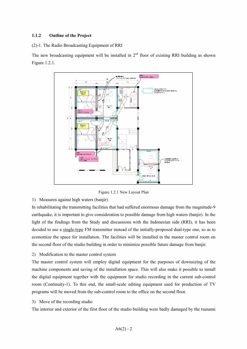
1.1.2 Outline of the Project
(2)-1. The Radio Broadcasting Equipment of RRI
The new broadcasting equipment will be installed in 2nd floor of existing RRI building as shown Figure 1.2.1.
Figure 1.2.1 New Layout Plan
1) Measures against high waters (banjir) In rehabilitating the transmitting facilities that had suffered enormous damage from the magnitude-9 earthquake, it is important to give consideration to possible damage from high waters (banjir). In the light of the findings from the Study and discussions with the Indonesian side (RRI), it has been decided to use a single-type FM transmitter instead of the initially-proposed dual-type one, so as to economize the space for installation. The facilities will be installed in the master control room on the second floor of the studio building in order to minimize possible future damage from banjir.
2) Modification to the master control system The master control system will employ digital equipment for the purposes of downsizing of the machine components and saving of the installation space. This will also make it possible to install the digital equipment together with the equipment for studio recording in the current sub-control room (Continuity-1). To this end, the small-scale editing equipment used for production of TV programs will be moved from the sub-control room to the office on the second floor.
3) Move of the recording studio The interior and exterior of the first floor of the studio building were badly damaged by the tsunami
A6(2) - 3
that occurred in December 2004. Taking also into account the damage from the resulting banjir, it is difficult to use the first floor as recording studios any longer. For this reason, instead of the original recording studio on the first floor, the announce booth on the second floor will be remodeled into a recording studio which can accommodate shooting of talk shows with several persons.
4) Public broadcasting role during the construction period and system switchover within the possible shortest time.
The installation work in this Project is considered as to take approximately two months. Since the RRI needs to continue providing daily-life information to the people in the Province of Aceh and calling on post-disaster reconstruction efforts, it is vital to keep its role as a public broadcaster even during the construction period. This Project enables the old and new systems to be operated simultaneously by downsizing the master control system and installing it in the sub-control room. Furthermore, it is also important to pay attention to the wiring to the transmitter in order to enable swift changeover of systems in the shortest possible time.
5) Restoration of the medium-wave transmitter The medium-wave transmitter with an output power of 10kW provided by Japan to the Indurapuri Transmitting Station has been partially broken down and is not in use for the time being. Since this transmitter covers a wider reception area (coverage) than an FM transmitter, it is regarded as one of the most important pieces of equipment for realizing the expected effects of the upgrading of the studio. In line with this, the Study Team, with supply of repair parts from Japanese manufactures, has been directly operating the transmitter and supervising the RRI as preliminary efforts in restoration. However, this can be excluded from the scope of the Project if the supervision of operation detects no further malfunction.
(2)-2. The Television Broadcasting Equipment of TVRI
The field survey has found that the following equipment is needed for rehabilitating the TV station.
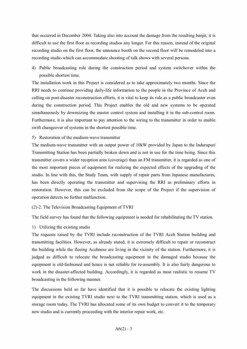
1) Utilizing the existing studio The requests raised by the TVRI include reconstruction of the TVRI Aceh Station building and transmitting facilities. However, as already stated, it is extremely difficult to repair or reconstruct the building while the fleeing Acehnese are living in the vicinity of the station. Furthermore, it is judged as difficult to relocate the broadcasting equipment in the damaged studio because the equipment is old-fashioned and hence is not reliable for re-assembly. It is also fairly dangerous to work in the disaster-affected building. Accordingly, it is regarded as most realistic to resume TV broadcasting in the following manner.
The discussions held so far have identified that it is possible to relocate the existing lighting equipment in the existing TVRI studio next to the TVRI transmitting station, which is used as a storage room today. The TVRI has allocated some of its own budget to convert it to the temporary new studio and is currently proceeding with the interior repair work, etc.

A6(2) - 4
2) Urgent Rehabilitation by OB VAN Utilizing the existing studio, broadcasting equipment, mainly OB vans and SNG cars, will be procured. The OB vans and SNG cars will record videos or broadcast live programs with the cameras onboard and also can control the cameras and communicate with the central station.
1.2 DESIGN CRITERIA
1.2.1 Configuration of Broadcasting Equipment Table 1.2.1 below shows the radio broadcasting equipment of RRI to be procured in this Project.
Table 1.2.1 Configuration of Broadcasting Equipment of RRI
No. Description Q’ty
1. Continuity Studio-1 System 1 lot
2. Continuity Studio-2 System 1 lot
3. Master Control System 1 lot
4. Editing Room System 1 lot
5. Radio OB(Out Broadcasting) VAN 1 lot
6. STL (Studio Transmission Link) 1 lot
7. SNG (Satellite News Gathering) Car 1 lot
8. 5kW FM Transmitter 1 lot
9. Measuring Equipment and Tools 1 lot
10. Consumable Parts 1 lot
11. Installation Materials 1 lot
Figure 1.2.2 is a schematic diagram of configuration of the equipment to be procured in this Project.

A6(2) - 5
Figure 1.2.2 Plan of the Project
Table 1.2.2 below shows the television broadcasting equipment of TVRI to be procured in this Project.
Table 1.2.2 Configuration of Broadcasting Equipment of TVRI
NO. Description Q’ ty
1. Field Recording ( ENG ) System 3 lots
2. 1:1 Editing System 1 lot
3. Video Non-Linear Editing System 1 lot
4. Sending Digital VTR (REC/PB) 1 set
5. OB VAN System 1 lot
6. SNG System 1 lot
7. Measuring Equipment 1 lot
8. Consumable Parts 1 lot
Figure 1.2.3 is a outline of configuration of the equipment to be procured in this Project.
A6(2) - 6
Figure 1.2.3 Plan of the Project
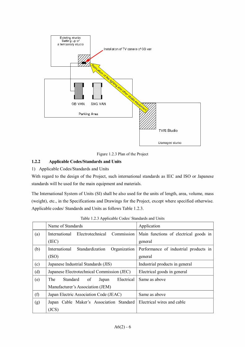
1.2.2 Applicable Codes/Standards and Units 1) Applicable Codes/Standards and Units With regard to the design of the Project, such international standards as IEC and ISO or Japanese standards will be used for the main equipment and materials.
The International System of Units (SI) shall be also used for the units of length, area, volume, mass (weight), etc., in the Specifications and Drawings for the Project, except where specified otherwise. Applicable codes/ Standards and Units as follows Table 1.2.3.
Table 1.2.3 Applicable Codes/ Standards and Units
Name of Standards Application
(a) International Electrotechnical Commission (IEC)
Main functions of electrical goods in general
(b) International Standardization Organization (ISO)
Performance of industrial products in general
(c) Japanese Industrial Standards (JIS) Industrial products in general
(d) Japanese Electrotechnical Commission (JEC) Electrical goods in general
(e) The Standard of Japan Electrical Manufacturer’s Association (JEM)
Same as above
(f) Japan Electric Association Code (JEAC) Same as above
(g) Japan Cable Maker’s Association Standard (JCS)
Electrical wires and cable

A6(2) - 7
(h) Electrical Industrial Association of Japan (EIAJ)
Electrical goods in general
(i) International Telecommunication Union (ITU) Electrical goods in general
(j) Society of Motion Picture and Television Engineers (SMPTE)
Broadcasting equipment in general
(k) Other related Japanese and International standards such as AES/EBU (Audio Engineering Society/European Broadcast Union)
Industrial products in general
2) Language The Specifications, Drawings and other documents for the Project shall be written in English.
1.3 DESIGN DRAWINGS
The following drawing shall be included in the draft tender documents.
The Broadcasting Equipment of RRI
Drawing No. Title Sy-001 Schematic Diagram of Signal Flow Sy-002 Block Diagram of Radio OB VAN Sy-008-1 Block Diagram of SNG CAR Sy-003 Block Diagram of Continuity Studio-1 System Sy-004 Block Diagram of Continuity Studio-2 System Sy-005 Block Diagram of Master Control System Sy-006 Block Diagram of Editing Room System Sy-007 Block Diagram of Radio OB VAN Audio System Sy-008-2 Block Diagram of SNG Car System Sy-009 Block Diagram of 5kW FM Transmitter / Antenna Sy-010 Block Diagram of Audio STL System Ps-001 Block Diagram of AC Power Facilities L-000 New Layout Plan L-001 Equipment Layout of Continuity Master Editing Room
The Broadcasting Equipment of TVRI
Drawing No. Title GE-01 Composition of Field Recording (ENG) System GE-02 Out Line of 1:1 Editing System GE-03 Out Line of Non-Liner Editing System

A6(2) - 8
G-01 Out Line of TV OB VAN System G-02 Block Diagram of SNG CAR System Sy-06 Block Diagram of 1:1 Editing System Sy-07 Block Diagram of Non-Liner Editing System Sy-01 Block Diagram of TV OB VAN Video System Sy-02 Block Diagram of TV OB VAN Audio System Sy-03 Block Diagram of TV OB VAN Intercom System Ex-01 Outside View of TV OB VAN Sy-04 Block Diagram of SNG CAR Video System Sy-05 Block Diagram of SNG CAR Audio System Ex-02 Outside View of SNG CAR
1.4 COST ESTIMATE 1.4.1 Radio Broadcasting Equipment
The total cost to implement this Project is estimated at approximately 357 million yen.
The following Table 1.4.1 table shows the breakdown of the project cost.
Table 1.4.1 Cost Estimation (Radio) <Unit: 1,000 yen>
No. Description Q’ty Amount I Radio Total (A+B+C) 357,000
A Equipment 294,800 1. Continuity Studio-1 System 1 lot 26,600 2. Continuity Studio-2 System 1 lot 26,600 3. Master Control System 1 lot 17,000 4. Editing Room System 1 lot 12,500 5. Radio OB(Out Broadcasting) VAN 1 lot 44,100 6. STL (Studio Transmission Link) 1 lot 5,400 7. SNG (Satellite News Gathering) Car 1 lot 70,400 8. 5kW FM Transmitter 1 lot 70,900 9. Measuring Equipment and Tools 1 lot 2,000 10. Consumable Parts 1 lot 100 11. Installation Materials 1 lot 19,200
B Transport and packaging 16,200
C Installation 46,000
1.4.2 TV Broadcasting Equipment
The total cost to implement this Project is estimated at approximately 453 million yen.
The following Table 1.4.2 shows the breakdown of the project cost.

A6(2) - 9
Table 1.4.2 Cost Estimation (TV) <Unit: 1,000 yen>
No. Description Q’ty Amount II TV Total (A+B+C) 453,000A Equipment 421,8001. Field Recording ( ENG ) System 3 lot 48,9002. 1:1 Editing System 1 lot 16,4003. Video Non-Linear Editing System 1 lot 20,200
4. Sending Digital VTR (REC/PB) 1 lot 6,000
5. OB VAN System 1 lot 196,100
6. SNG System 1 lot 116,600
7. Measuring Equipment 1 lot 10,600
8. Consumable Parts 1 lot 7,000
B Transport and packaging 21,200
C Installation 10,000

A6(2) - 10
CHAPTER 2 PREPARATION OF TECHNICAL REPORT
2.1 TENDER CONDITION
2.1.1 Points to be Considered in Installing the Equipment
The following points need to be considered in the installation work.
The supplier will be responsible for reparation of the broadcasting system even after the delivery of equipment in order to secure smooth operation and maintenance. Furthermore, in the implementation stage, it is essential to fully understand the urgency of the Project and the social responsibility of RRI as a public broadcaster as well as instructing the equipment supplier with the basic philosophy of human life and main emphasis on quality control and prevention of public disaster and damage to the existing equipment. It is also important to select a contractor in the tender who will help in good faith Indonesia carry out the operation and maintenance.
In the construction supervision phase, it is essential to prepare and plan temporary broadcasting facilities, system switchover and test broadcasts with close attention to prevention of broadcasting accidents.
The counterpart has experience in handling broadcasting equipment but is not familiar enough with operation of digital equipment. Therefore, it is necessary that the equipment supplier provides OJT to the Indonesian side to ensure that operation and maintenance will not be interrupted in any way.
2.1.2 Conditions for Tender Participants
In the upgrading of equipment at RRI Banda Aceh Station, which is a public broadcaster, the contractor needs to be able to replace the system, instruct on operation up to the test broadcast phase, and ensure the realization of the expected effects of new equipment while keeping public broadcasting. Therefore, the contractor is expected to have a certain degree of experiences and performance records. For this reason, the tenderers are expected to be as follows.
1) Trading company or manufacturer who has responsibly delivered a system in Indonesia.
2) Trading company or manufacturer who has responsibly delivered a system to the RRI.
3) Trading company or manufacturer who has an office in Indonesia or Japan.
2.2 TECHNICAL REPORT
Technical report was prepared. Composition of the report is same as that of the Project: RECOVERY OF WATER SUPPLY SYSTEM IN BANDA ACEH CITY. JICA Study Team has produced Volumes II: Technical Specifications and III: Drawings as Technical Report.

APPENDIX 7
GIS FOR ARRIS (ACEH REHABILITATION AND
RECONSTRUCTION INFORMATION SYSTEM)

i
APPENDIX 7 GIS FOR ARRIS (ACEH REHABILITATION AND RECONSTRUCTION INFORMATION SYSTEM)
Table of Contents Page
CHAPTER 1 INTRODUCTION ..................................................................................... A7-1 1.1 SITUATION AFTER TSUNAMI ............................................................................... A7-1 1.2 BACKGROUND OF ARRIS ..................................................................................... A7-1 CHAPTER 2 OBTAINED GEOGRAPHIC INFORMATION .......................................... A7-3 2.1 IKONOS SATELLITE IMAGES................................................................................. A7-3 2.2 EXISTING MAPS ..................................................................................................... A7-4
2.2.1 BPN Topographic Maps ............................................................................. A7-4 2.2.2 Map of Banda Aceh ................................................................................... A7-5 2.2.3 BAKOSURTANAL Topographic Maps ...................................................... A7-5
CHAPTER 3 FORMULATION OF ARRIS ..................................................................... A7-7 3.1 BASIC PROCEDURE ............................................................................................... A7-7
3.1.1 Procedure and Concept .............................................................................. A7-7 3.1.2 Software and Data Format .......................................................................... A7-9
3.2 DATA PREPARATION ............................................................................................. A7-9 3.2.1 First Stage .................................................................................................. A7-9 3.2.2 Second Stage ............................................................................................. A7-9
3.3 BASIC VERSION OF ARRIS ..................................................................................A7-11 3.4 COMPLETE VERSION OF ARRIS ........................................................................ A7-13
3.4.1 Basic Methodology .................................................................................. A7-13 3.4.2 Contents of ARRIS .................................................................................. A7-15
CHAPTER 4 UTILIZATION OF ARRIS AND MAPS FOR PLANNING ..................... A7-18 4.1 UTILIZATION OF ARRIS FOR PLANNING ......................................................... A7-18
4.1.1 Quick Tsunami Damage Assessment ........................................................ A7-18 4.1.2 Hazard and Risk Assessment .................................................................... A7-18 4.1.3 Post Tsunami City Plan Concept ............................................................... A7-18 4.1.4 Road Planning ......................................................................................... A7-19 4.1.5 Disaster Mitigation and Management Plan ............................................... A7-19 4.1.6 Land Use Plan .......................................................................................... A7-20 4.1.7 Population Plan ........................................................................................ A7-20

ii
4.1.8 Planning for School ................................................................................. A7-20 4.1.9 Planning for Health Centers ..................................................................... A7-21 4.1.10 Planning for Water Supply ....................................................................... A7-21
4.2 MAPS FOR PLANNING ........................................................................................ A7-21 CHAPTER 5 PLAN OF OPERATION AND MAINTENANCE OF ARRIS .................. A7-23 5.1 IMPORTANT ORGANIZTIONS ............................................................................ A7-23 5.2 PLAN OF OPERATION AND MAINTENANCE .................................................... A7-24
5.2.1 Data Dissemination .................................................................................. A7-24 5.2.2 Operation ................................................................................................. A7-24 5.2.3 Maintenance ............................................................................................ A7-25 5.2.4 Technical Support .................................................................................... A7-26
CHAPTER 6 DATA STRUCTURE ............................................................................... A7-27 6.1 DATA STRUCTURE ............................................................................................... A7-27
6.1.1 Main Data Folders ................................................................................... A7-27 6.1.2 Sub Data Folders ...................................................................................... A7-27
6.2 METADATA OF ARRIS THEMATIC GIS LAYERS ............................................... A7-30 CHAPTER 7 PLANNING TOOLS FOR ARRIS USER ................................................ A7-31 7.1 OVERVIEW OF ARRIS TOOL ............................................................................... A7-31
7.1.1 Main Functions ........................................................................................ A7-31 7.1.2 Core Functions ......................................................................................... A7-31
7.2 SYSTEM SUMMARY ............................................................................................ A7-31 7.2.1 System Requirements ............................................................................... A7-31 7.2.2 System Architecture ................................................................................. A7-32
7.3 OPERATION OF ARRIS TOOL (PART 1) .............................................................. A7-33 7.3.1 Starting ARRIS Tool ................................................................................ A7-33 7.3.2 ARRIS Tool Screen Contents ................................................................... A7-33 7.3.3 Items in Menu .......................................................................................... A7-34 7.3.4 Closing ARRIS Tool ................................................................................ A7-34
7.4 OPERATION OF ARRIS TOOL (PART 2) .............................................................. A7-35 7.4.1 Administrative Boundary Selector Module ............................................... A7-35 7.4.2 Sector Planning Modules (Data Setting) ................................................... A7-37
7.5 SECTOR PLANNING MODULE (Manipulation) ................................................... A7-39 7.5.1 Escape Building Planning Module ............................................................ A7-39 7.5.2 Road Planning Module ............................................................................. A7-41 7.5.3 Health/Medical Planning Module ............................................................. A7-42

iii
7.5.4 Education Planning Module ..................................................................... A7-43 7.6 CREATE BUFFER POLYGON MODULE .............................................................. A7-43
7.6.1 User Point Layer Tool .............................................................................. A7-43 7.6.2 Add User’s Point Layer ............................................................................ A7-43 7.6.3 Add User’s Point Layer ............................................................................ A7-45 7.6.4 Creating Buffer Polygons for a User’s Point Layer ................................... A7-45
CHAPTER 8 PRESENTATION AND DEMONSTRATION OF ARRIS ........................ A7-48

iv
List of Tables Page Table 2.1.1 List of Basic Map Images Obtained by the JICA Study Team .............. A7-3 Table 2.1.2 List of IKONOS Satellite Images Procured by the JICA Study Team ... A7-4 Table 2.2.1 Number of BPN Maps ......................................................................... A7-4 Table 2.2.2 List of BAKOSURTANAL Topographic Maps .................................... A7-6 Table 3.3.1 List of Prepared Data for Basic Version of ARRIS ............................. A7-12 Table 3.4.1 Basic Geographic Features from Provisional Digital Maps ................. A7-14 Table 3.4.2 File Formats for Information and Data in ARRIS ............................... A7-15 Table 4.1.1 Adopted Ratio for Estimation of School-aged Childeren Numbers ..... A7-20 Table 4.1.2 School Buffers Zones (Circles) Used, for Planning ............................ A7-20 Table 4.2.1 Map Reference IDs and Titles of Maps .............................................. A7-21 Table 4.2.2 Category and Number of Thematic Maps ........................................... A7-22 Table 7.3.1 Additional Menu Items for Tools ....................................................... A7-34 Table 7.3.2 How to Close Tools ........................................................................... A7-34 Table 7.4.1 Tools for Creation of Buffer Polygons ............................................... A7-37
List of Figures Figure 1.1.1 Location of Banda Aceh ...................................................................... A7-2 Figure 2.1.1 Coverage of Digital Maps and IKONOS Images .................................. A7-3 Figure 2.2.1 Coverage of BPN Topographic Maps ................................................... A7-4 Figure 2.2.2 “Map of Banda Aceh” .......................................................................... A7-5 Figure 2.2.3 Coverage of BPN Topographic Maps ................................................... A7-6 Figure 3.1.1 Development Plan and Utilization of ARRIS ....................................... A7-7 Figure 3.1.2 Concept of Formulation of Basic Version of ARRIS ............................ A7-8 Figure 3.1.3 Concept of Formulation of Complete Version of ARRIS ...................... A7-8 Figure 3.2.1 Preparation of Data for ARRIS .......................................................... A7-10 Figure 3.3.1 Coverage of IKONOS Images for the Basic Version of ARRIS .......... A7-11 Figure 3.4.1 Data Arrangement Scheme for ARRIS ............................................... A7-16 Figure 3.4.2 Function of Data Folders .................................................................... A7-16 Figure 3.4.3 Sample View Images of ARRIS Map Catalog .................................... A7-17 Figure 5.1.1 Organizational Framework for Operation and Maintenance of ARRIS
(Plan) ................................................................................................ A7-23 Figure 5.2.1 Data Dissemination Flow (Originally Planned by BAPPENAS) ......... A7-24 Figure 5.2.3 (a) Concept on Data Update/Maintenance (Recommendation) ............ A7-25 Figure 5.2.3 (b) Data Integration Flow (Recommendation) .................................... A7-25 Figure 5.2.4 Technical Support Plan on ARRIS (Recommendation) ....................... A7-26 Figure 6.1.1 Constitution of “ARRIS-GIS” Folder ................................................. A7-27

v
Figure 6.1.2 Constitution of “Catalog” Folder ........................................................ A7-27 Figure 6.1.3 Contents of “ESRI_MXDfiles” Folder ............................................... A7-28 Figure 6.1.4 Constitution of “ESRI_Shapefiles” Folder ......................................... A7-28 Figure 6.1.5 Constitution of “PDF_Maps” Folder .................................................. A7-29 Figure 6.1.6 Constitution of “Tatuk_Projects” Folder ............................................ A7-29 Figure 7.1.1 Concept on Creation of Buffer Polygons from User’s Points .............. A7-31 Figure 7.2.1 Basic System Architecture ................................................................. A7-32 Figure 7.2.2 How to Make Copy of Folder and Files for Tools ............................... A7-32 Figure 7.3.1 ARRIS_83.mxd (ARRIS_90.mxd) Icon ............................................. A7-33 Figure 7.3.2 Screen Contents of ARRIS_83 (90).mxd ............................................ A7-33 Figure 7.4.1 Operation Flow of Administrative Boundary Selector ........................ A7-35 Figure 7.4.2 Administrative Boundary Selector in [ARRIS] Menu ......................... A7-35 Figure 7.4.3 Administrative Boundary Layer Selection Dialog (Window) .............. A7-36 Figure 7.4.4 Zoom to a Specific Kecamatan and Desa Dialog (Window) ............... A7-36 Figure 7.4.5 Label Visibility Button and Layer Visibility Button ........................... A7-37 Figure 7.4.6 Operation Flow for Sector Planning Modules ..................................... A7-38 Figure 7.4.7 Confirmation and Error Message Windows in Saving Data Settings ... A7-38 Figure 7.4.8 Confirmation and Error Message Windows in Loading Data Settings . A7-39 Figure 7.5.1 Operation Flow for Sector Planning Modules ..................................... A7-39 Figure 7.5.2 “Draw Buffer” Dialog Window .......................................................... A7-40 Figure 7.5.3 “Error Message” Dialog Window ....................................................... A7-40 Figure 7.5.4 “Select Features” and “Select by Attributes” Dialog Window ............. A7-40 Figure 7.5.5 “Input Buffer Distance” Dialog Window ............................................ A7-41 Figure 7.5.6 “Save Drawn Buffers” Dialog Window .............................................. A7-41 Figure 7.5.7 “Continue to Create Buffers?” Dialog Window .................................. A7-41 Figure 7.5.8 Operation flow for Road Planning Module ......................................... A7-42 Figure 7.5.9 Operation Flow for Road Planning Module ........................................ A7-42 Figure 7.5.10 Operation flow for Education Planning Module ................................. A7-43 Figure 7.6.1 Items in “User’s Point Layer” Sub-menu ............................................ A7-43 Figure 7.6.2 “Add Layer” Dialog and “Open Point Layer” Dialog Windows .......... A7-44 Figure 7.6.3 User Dialog for Specifying Attributes of a New Shapefile .................. A7-44 Figure 7.6.4 “Draw Buffer” Dialog Window .......................................................... A7-45 Figure 7.6.5 “Error Message” Dialog Window ....................................................... A7-45 Figure 7.6.6 “Select Feature(s)” Dialog Window ................................................... A7-46 Figure 7.6.7 “Input Buffer Distance” Dialog Window ............................................ A7-46 Figure 7.6.8 “Input Buffer Distance” Dialog Window ............................................ A7-46 Figure 7.6.9 “Continue to create buffers?” Dialog Window ................................... A7-47

A7 - 1
CHAPTER 1 INTRODUCTION
1.1 SITUATION AFTER TSUNAMI
As of the middle of March 2005 after the tsunami occurred on December 2004, relatively larger scale maps, geographic data and spatial information were not available to the people in charge of preparing plans for the rehabilitation and reconstruction of Banda Aceh City. However, these maps and geographic information would be needed by the JICA Study Team for preparation of a master plan for rehabilitation and reconstruction of Banda Aceh City.
Previously, the National Land Institute (BPN) had prepared topographic maps with scales of 1:1,000 and 1:2,500 in 1993 and 1997, respectively. These maps cover Banda Aceh City and the surrounding vicinity. The aerial photographs that were used for the base imagery and to plot features shown on the maps were acquired in 1970’s. Unfortunately, those maps and aerial photographs were not suitable for use in the rehabilitation and reconstruction planning process because the base imagery and maps derived from it were very outdated. The actual situation that existed in the Banda Aceh City immediately prior to the tsunami on 26 December 2004 would have been quite different to that shown on the maps. In addition, no information could be obtained about areas which had been washed out and devastated by the tsunami, specifically in the northwestern half of the city.
1.2 BACKGROUND OF ARRIS
JICA and the JICA Study Team supported the Republic of Indonesia to build a geographic information platform and prepare relevant maps and data. These maps and data have been able to be used efficiently for rehabilitation and reconstruction planning of Banda Aceh City.
The following two points were the final goals of the activities related to geographic matters in the Study:
To prepare digital topographic maps for Banda Aceh City Digital topographic maps and related data would be prepared and used as base maps with a geographical information system (GIS). The basic GIS data would be prepared at a nominal scale of 1:2,000.
To develop an Aceh Rehabilitation and Reconstruction Information System A GIS named “Aceh Rehabilitation and Reconstruction Information System (ARRIS)” would be established and utilized for various purposes in the rehabilitation and reconstruction planning of Banda Aceh City. In addition, ARRIS would be shared by various groups who were concerned with the activities of rehabilitation and reconstruction of Banda Aceh City.

A7 - 2
The target area of the digital mapping and ARRIS is Banda Aceh City (about 68km2) and its neighboring towns and villages, which are located in the northern end of Sumatra in Indonesia, is shown in Figure 1.1.1 below.
Source: JICA Study Team
Figure 1.1.1 Location of Banda Aceh

A7 - 3
CHAPTER 2 OBTAINED GEOGRAPHIC INFORMATION
The JICA Study Team acquired or obtained the relevant geographic information, which were considered to be useful for the Study (Table 2.1.1).
Table 2.1.1 List of Base Map Images Obtained by the JICA Study Team
Map Contents Scale IKONOS Satellite Images IKONOS satellite images acquired before/after the tsunami. 1:5,000 1:1,000 Topographic Maps Scanned 1:1,000 topographic maps originally prepared by
BPN. 1:5,000
1:2,500 Topographic Maps Scanned 1:2,500 topographic maps originally prepared by BPN.
1:5,000
1:15,750 Topographic Maps
Scanned city map. 1:15,750
1:50,000 Topographic Maps
BAKOSURTANAL 1:50,000 topographic maps. 1:50,000
Source: JICA Study Team
2.1 IKONOS SATELLITE IMAGES
The IKONOS satellite images acquired before and after the tsunami disaster were used as one of the most important base image data for the Study.
Source: Japan Space Imaging and JICA Study Team
Figure 2.1.1 Coverage of Digital Maps and IKONOS Images
Figure 2.1.1 above shows the coverage of the IKONOS satellite images, which were procured in The Study. The original images were prepared with approximately one (1) meter per pixel resolution.
Table 2.1.2 below shows the acquisition date of the IKONOS satellite images before and after the tsunami disaster.

A7 - 4
Table 2.1.2 List of IKONOS Satellite Images Procured by the JICA Study Team
Target Area Acquisition Date of Acquisition Coastal areas of Banda Aceh 100 km2 Before the tsunami on Dec. 26, 2004 18 June 2004 Coastal areas of Banda Aceh 100 km2 After the tsunami on Dec. 26, 2004 29 December 2004 Suburbs of Banda Aceh 250 km2 After the tsunami on Dec. 26, 2004 29 December 2004 Suburbs of Banda Aceh 75 km2 After the tsunami on Dec. 26, 2004 29 January 2005 West coast of northwestern Sumatra 62 km2 After the tsunami on Dec. 26, 2004 29 December 2004 East coast of northeastern Sumatra 22 km2 After the tsunami on Dec. 26, 2004 15 June 2005
Source: JICA Study Team
2.2 EXISTING MAPS
2.2.1 BPN Topographic Maps
The existing topographic maps with scales of 1:1,000 and 1:2,500 covering Banda Aceh City were obtained by the JICA Study Team, and used as the geographic reference for The Study. These maps were supplied as scanned digital images (TIFF format). The original maps were prepared by BPN in 1994 and 1998. Aerial photographs used for preparation of those maps were acquired from 1975 until 1996. Figure 2.2.1 below shows the coverage of the BPN maps for Banda Aceh City and its suburbs, and Table 2.2.1 show the number of the map sheets.
Source: JICA Study Team
Figure 2.2.1 Coverage of BPN Topographic Maps
Table 2.2.1 Number of BPN Maps
Nominal Scale Number of Sheet Base Aerial Photographs Published 1:2,500 35 sheets 1975 1994 1:1,000 240 sheets 1996 1998
Source: BPN

A7 - 5
2.2.2 Map of Banda Aceh
A city map named “Map of Banda Aceh” that has been published by an Indonesian company (U.D. Fajar Baru) was used to identify and extract administrative area boundaries, of which are desa (a village within a city) and kecamatan (a sub-district of a city; lager than desa)” within Banda Aceh City. This map, which is shown in Figure 2.2.2 below, was the only map available for identifying the administrative boundaries of kecamatans and desas within Banda Aceh City in the first stage of the Study. The nominal scale of the map is 1:15,750. However, the accuracy of this map was unknown. In the Study, the map was digitally scanned and then geometrically rectified as much as possible using the ground control points (GCPs) identifiable on the BPN maps or the IKONOS satellite images that were mentioned above.
Source: U.D Fajar Baru
Figure 2.2.2 “Map of Banda Aceh”
2.2.3 BAKOSURTANAL Topographic Maps
Topographic maps with a scale of 1:50,000 were also scanned and processed as reference images. These maps were generated by the National Coordination Agency for Surveys and Mapping (BAKOSURTNAL), and published firstly in 1978. The scanned map images were used as a supplemental reference, as shown in Figure 2.2.3 below.
The map sheet names are listed in Table 2.2.2

A7 - 6
Source: BAKOSURTANAL
Figure 2.2.3 Coverage of 1:50,000 Scale BAKOSURTANAL Topographic Maps
Table 2.2.2 List of BAKOSURTANAL Topographic Maps
Map Sheet No.
Publishing Year Acquisition Year of Aerial Photographs for Mapping
Scale of Aerial Photographs for Mapping
0421-51 1978 1977 1:100,000 0421-52 1978 1977 1:100,000 0421-23 1978 1977 1:100,000 0421-24 1978 1977 1:100,000
Source: BAKOSURTANAL

A7 - 7
CHAPTER 3 FORMULATION OF ARRIS
3.1 BASIC PROCEDURE
3.1.1 Procedure and Concept
Since urgency was required for the JICA Study, formulation of the ARRIS had been implemented by two steps (Figure 3.1.1).
ARRIS-Basic(Simplified ARRIS)
ARRIS-Complete(Completed ARRIS)
Tsunami damage evaluation
Comparison of conditionsbefore and after the disaster
Extraction of issues to be solved
Disaster Management Plan
Data
Landuse Plan
Population Framework
Sectoral Plan Community Plans
New City Concept
Policy-/Decision-Making
Data Integration/Sharing Data
Source: JICA Study Team
Figure 3.1.1 Development Plan and Utilization of ARRIS
Basic Version of ARRIS The basic version of ARRIS had been developed (based on the IKONOS satellite images), as a first step, to understand the physical conditions in Banda Aceh City by comparing before and after conditions. The related work for development of the simplified ARRIS had been finished by the end of April, 2005. Figure 3.1.2 shows a concept of the basic version of ARRIS.

Field Survey,
Photo InterpretationPhoto Interpretation,
and Digitizing
A7-8
STATISTICSData Existing Map
Existing Maps preparedin 1993 and 1997,Scale= 1:2,500 and 1:1,000
IKONOSSatellite Imagery
High- resolution satellite images acquired before/after Tsunami
Damage AssessmentData
Spot heights and flow directions of Tsunami Water;House/Building Damage; andRe-settlement potential areas
GIS Data
Vector datasets digitized based on IKONOS Satellite Imagery
End of April 2005
Statistical data prepared after Tsunami
ARRIS (GIS)Basic Version
Nominal scale 1:5,000,based on IKONOS Satellite imagery
Source: JICA Study Team
Figure 3.1.2 Concept of Formulation of Basic Version of ARRIS
Complete Version of ARRIS Since the basic version of ARRIS had been completed, the complete version of ARRIS was developed. The complete version of ARRIS was planned to be developed for supporting the rehabilitation/reconstruction plans to be prepared by the JICA Study Team, and contains relevant GIS data and thematic maps. Finally, the ARRIS also contains the GIS data of the digital topographic maps of Banda Aceh City with a nominal scale of 1:2,000. Figure 3.1.3 shows a
concept of the complete version of ARRIS.
Road/TransportPlan
Social Consideration
Landuse PlanLand Re-adjustment
Plan
Drainage SystemPlan
HealthCenter
Plan
Disaster Mitigation
Plan
End of December, 2005
ARRISComplete VersionBased on Topographic Map
with a Scale of 1:2,000
ARRISBasic Version
Nominal Scale: 1:5,000Based on IKONOS
Digital Topographic MapNominal Scale: 1:2,000
Based on Aerial Photo Imageryacquired on June 6, 2005
Education Plan
ARRIS DatabaseARRIS Database
End of April, 2005
Micro Landuse Plan(Case Studies)
Source: JICA Study Team
Figure 3.1.3 Concept of Formulation of Complete Version of ARRIS
The formation of ARRIS was finished at the end of December, 2005.
Water SupplyPlan

A7 - 9
3.1.2 Software and Data Format
(1) GIS Software
ArcGIS (Arcview 8 and 9) for Windows was used as a standard of GIS software in developing ARRIS and the geographic data.
(2) Vector Data Format
ESRI Shapefile was used as a standard file format for GIS data of the ARRIS. The Shapefile is convertible to other vector data format such as AutoCAD dxf, using the relevant software.
(3) Raster Data Format
GeoTIFF is used as a standard raster data format for GIS data in ARRIS, and is utilizable with ArcGIS.
(4) Projection and Datum
All the geographic data for ARRIS were projected for UTM Zone 46 N (WGS 1984).
3.2 DATA PREPARATION
3.2.1 First Stage
Data for ARRIS were prepared in accordance with the planned development stages of ARRIS. In the first stage, between the middle of March and the end of April 2005, the basic version of ARRIS was to be used to:
Understand the affect of tsunami damage on Banda Aceh City; Disseminate and share information among those who were interested in activities for
rehabilitation and reconstruction of Banda Aceh; and Review and support reconstruction planning and activities in an initial stage.
A basic GIS database for the basic version of ARRIS was quickly prepared by the JICA Study Team in this stage. The basic GIS database covers an area of 100km2 that include Banda Aceh City. Geographic features (e.g., roads, buildings, bridges, lands, and water bodies) were digitized at a nominal scale of 1:5,000 by interpreting the IKONOS satellite images (before and after the tsunami) and existing maps (prepared before the tsunami). The related existing thematic maps or other data were needed, such as administrative boundaries and public facilities, were digitized as GIS data.
3.2.2 Second Stage
In the second stage, between the beginning of May and the end of December 2005, the complete version of ARRIS was expected to:
Be utilized for city planning or local area planning in the Study; Include precise base maps (digital topographic maps with a nominal scale of 1:2,000); and

A7 - 10
Include all geographic data generated in the Study. Additional data for the complete version of ARRIS had been prepared since the beginning of May 2005. These data had been analyzed or utilized with ARRIS in the Study, and the results of the analysis and utilization were incorporated into the database, too.
Pre-tsunami IKONOS
satellite images(GeoTIFF)
Post-tsunami IKONOS
satellite images(GeoTiff)
Banda AcehCity Map(1:15,750)
BPN Mapsof Banda Aceh
(1:2,500)
BPN Mapsof Banda Aceh
(1:1,000)
Topographic Maps(1:50,000)
Digital scanning
Geo-rectification
“Raw” raster images(TIFF)
Geo-rectification
Rectified rasterimages(Base imagery for Banda Aceh
City; GeoTIFF)
Pre-tsunami geo-rectified
images
Post-tsunami geo-rectified
images
Geo-rectified topographic topographic
maps(Base imagery for surrounding areas;
GeoTIFF)
Geo-rectification
Geo-rectification
RectifiedMap of Banda
Aceh(City Map)
Pre-tsunamiground feature data(ESRI ShapeFile)
Post-tunamiground feature data(ESRI ShapeFile)
Pre-tsunamiground feature data(ESRI ShapeFile)
Image InterpretationImage
Interpretation
Administrative boundary
(Desa and Kecamantan) Boundary
(ESRI ShapeFile)
ARRIS(Basic version)
Collected Statistical Data
Quick Damage Assessment
Results
Digitization
Utilization for PlanningCompleted in April, 2005
ARRIS(Complete version)
Digital Maps(1:2,000)
Provisional digital maps (GIS Maps)
(S=1:2,000)
Completed in December, 2005
Periodic Update Thematic maps prepared in planning
Spatial Plansincluded in
“Blue Print”
Source: JICA Study Team
Figure 3.2.1 Preparation of Data for ARRIS

A7 - 11
3.3 BASIC VERSION OF ARRIS
The basic version of ARRIS targeted an area of 100 km2, which includes Banda Aceh City and its suburbs and almost coincides with the coverage of the pre-tsunami IKONOS satellite images procured by the JICA Study Team for the first stage of the Study, especially coastal areas, as shown in Figure 3.3.1 below. A targeted nominal scale of the GIS layers in the basic version of ARRIS was planned at 1:5,000.
Source: BAKOSURTANAL and JICA Study Team
Figure 3.3.1 Coverage of IKONOS Images for the basic version of ARRIS
The needed spatial data were prepared as the vector data (shapefiles) by digitizing the features shown on the base map images, e.g., the IKONOS satellite images, and scanned maps (Table 3.3.1).

A7 - 12
Table 3.3.1 List of Prepared Data for Basic Version of ARRIS
Type Feature/Theme Method of digitizing and contents Scale Vector (Point)
Building Building features extracted by interpreting IKONOS satellite images before/after the tsunami.
1:5,000
Vector (Point)
Damage assessment point Locations checked in the damage assessment; each location was identified with handheld GPS.
1:5,000
Vector (Point)
Health/Medical Location of hospitals, clinics and health care centers located after the tsunami; facilities were identified based on existing location maps.
1:5,000
Vector (Point)
School/Education Location of schools located before the tsunami; each school was identified on the satellite images by a person who knew the locations of the schools.
1:5,000
Vector (Line)
Roads Road features extracted by interpreting IKONOS satellite images acquired before/after the tsunami.
1:5,000
Vector (Line)
Water Pipes Location of water distribution mains; original data were prepared in CAD data format; a map with a scale of 1:15,750 was used as the base map and converted to GIS data for Simplified ARRIS.
1:15,750
Vector (Line)
Bridges Bridge features extracted by interpreting IKONOS satellite images acquired before/after the tsunami.
1:5,000
Vector (Line)
Maximum Height of Tsunami Water
Contours showing the maximum water levels in the tsunami; generated automatically from GIS data of the spot damage assessment map using a GIS function.
1:5,000
Vector (Polygon)
Land Land features extracted by interpreting IKONOS satellite images acquired before/after the tsunami.
1:5,000
Vector (Polygon)
Building Building features having a side of 30 m or longer extracted by interpreting IKONOS satellite images acquired before/after the tsunami.
1:5,000
Vector (Polygon)
Vacant Land 50 m-mesh data classifying vacant land and utilized land; classified by interpreting IKONOS satellite images acquired after the tsunami.
1:5,000
Vector (Polygon)
Building Damage Assessment Map
100 m-mesh data classifying building damage by the tsunami; classified by interpreting IKONOS satellite images before/after the tsunami.
1:5,000
Vector (Polygon)
Administrative Boundary Administrative boundaries of Banda Aceh City and its kecamantans and desas shown on the city map of Banda Aceh.
1:15,750
Vector (Polygon)
Landuse Plan Future landuse plan for Banda Aceh City prepared in April 2005.
1:15,750
Vector (Polygon)
Spatial Plan Future spatial plan for Banda Aceh City and neighboring areas shown in “Blue Print” prepared in April 2005.
1:50,000
Raster (Image)
IKONOS Satellite Images IKONOS satellite images acquired before/after the tsunami; geo-rectified based on existing maps with scales of 1:1,000 and 1:2,500
1:5,000
Raster (Image)
1:1,000 Topographic Maps
Scanned 1:1,000 topographic maps originally prepared by BPN; geo-rectified in UTM Zone 46N
1:5,000
Raster (Image)
1:2,500 Topographic Maps
Scanned 1:2,500 topographic maps originally prepared by BPN; geo-rectified in UTM Zone 46N
1:5,000
Raster (Image)
1:15,750 Topographic Maps
Scanned city map; geo-rectified in UTM Zone 46N 1:15,750
Raster (Image)
1:50,000 Topographic Maps
BAKOSURTANAL 1:50,000 topographic maps; geo-rectified in UTM Zone 46N
1:50,000
Source: JICA Study Team
Since there was not any relevant communication infrastructure for the basic version of ARRIS, the GIS data sets were planned to deliver data on CD-ROM or by e-mail to persons concerned with the project or who were responsible for the rehabilitation and reconstruction of Banda Aceh in the first stage of the Study.

A7 - 13
The GIS data (both vector and raster data sets) were delivered by the JICA Study Team to BAPPEDA Province-NAD, UNSYIAH and BAPPENAS by May 2, 2005. After the first delivery of the basic data to these three organizations, some GIS data layers were revised as needed. The updated GIS data sets were quickly distributed by the Study Team and sent through the internet to the three (3) ARRIS holders (BAPPEDA Province-NAD, UNSYIAH and BAPPENAS).
3.4 COMPLETE VERSION OF ARRIS
3.4.1 Basic Methodology
The complete version of ARRIS had been developed since May 2005. Especially since post-tsunami digital topographic maps with a nominal scale of 1:2,000 were indispensable for preparing various plans in the Study that had to be finalized by the end of August 2005, it was decided to prepare a provisional version of the maps of Banda Aceh City by digitizing the available (but outdated) 1:1,000 and 1:2,500 scale maps. Although not ideal, this provided a reasonable alternative because even though features such as buildings and roads shown on the old maps do not necessarily match the pre-tsunami situation, the land surface contour would generally be similar to the post-tsunami situation, except where some development work etc. has occurred in the intervening time period. Doing this allowed the IKONOS satellite images to provisionally be ortho-rectified by using the results of the JICA Study Team’s control point survey, and matching features on the digitized version of the existing topographic maps and orhto-rectified IKONOS imagery to be prepared in June 2005, and the results were supplied to the other Study Team members whose planning work depend on having digital maps and recent imagery.
The following methodologies were basically applied for the complete version as shown in Figure 3.2.1.
1) Conversion of the provisional (1:2,000) digital topographic maps prepared in July 2005 to ESRI shapefiles (the features included in the provisional digital maps were shown in Table 3.2 below.);
2) Revision of the GIS data for the basic version of ARRIS; 3) Digitizing other geographic features, planning maps and relevant data; 4) Replace of the digital topographic maps of Banda Aceh City with a nominal scale of 1:2,000
from the provisional version prepared in July to the complete version completed in December, 2005.
By preparing the provisional digital maps of Banda Aceh City, more detailed basic geographic feature data were able to be used as listed in Table 3.4.1 below. These data have been processed as thematic data for use in planning work done as part of the Study.

A7 - 14
Table 3.4.1 Basic Geographic Features from Provisional Digital Maps
Category Feature Name Point Line Polygon Boundary City boundary Yes Boundary Sub district boundary Yes Boundary Village boundary Yes Road Main Road: parallel lines Yes Yes Road Other Road: parallel lines Yes Road Footpath: centerline Yes Road Bridge (Main Road) Yes Yes Yes Road Bridge (Other Road) Yes Yes Yes Road Bridge (Footpath) Yes Road Culvert Yes Road Main Road Centerline Yes Road Other Road Centerline Yes Road Bridge Centerline (Main Road) Yes Road Bridge Centerline (Other Road) Yes House House: with Roof Yes House Mosque Yes House Church Yes House Temple Yes House School Yes House Hospital Yes House Dispensary Yes House Government office Yes House Public office Yes House Factory Yes House Transformer substation Yes House Other Yes Yes Land mark Tower Yes Land mark Electricity powerline Land mark Cemetry Yes Yes Land mark Park Yes Yes Water River(width over 3m): parallel lines Yes Yes Water River(width under 3m): centerline Yes Water Water way(width under 3m): centerline Yes Water Coast line Yes Water Lake, Pond Yes Water Swamp, Marsh Yes Water Fish pond Yes Water River centerline (width over 3m) Yes Water Water way centerline (width over 3m) Yes Vegetation Trees Yes Yes Vegetation Grassland Yes Vegetation Open space, Wasteland Yes Vegetation Agricultural land Yes Vegetation Mangrove Yes Vegetation Other (residential area) Yes Vegetation Cultivation limit Yes Geodetic points GPS survey point Yes Geodetic points Leveling survey point Yes
Source: JICA Study Team
As for the thematic data layers, those were prepared through the creation of each thematic maps, which were required in the planning by the JICA Study Team mentioned in CHAPTER 4.
A7 - 15
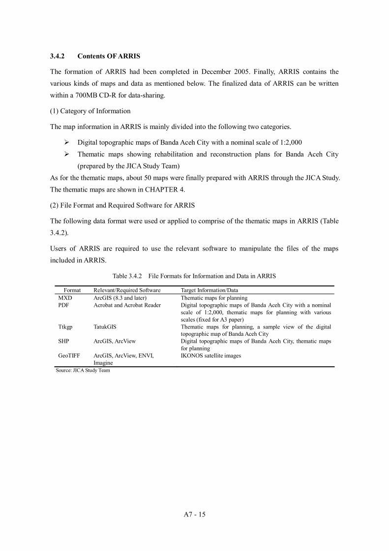
3.4.2 Contents OF ARRIS
The formation of ARRIS had been completed in December 2005. Finally, ARRIS contains the various kinds of maps and data as mentioned below. The finalized data of ARRIS can be written within a 700MB CD-R for data-sharing.
(1) Category of Information
The map information in ARRIS is mainly divided into the following two categories.
Digital topographic maps of Banda Aceh City with a nominal scale of 1:2,000 Thematic maps showing rehabilitation and reconstruction plans for Banda Aceh City
(prepared by the JICA Study Team) As for the thematic maps, about 50 maps were finally prepared with ARRIS through the JICA Study. The thematic maps are shown in CHAPTER 4.
(2) File Format and Required Software for ARRIS
The following data format were used or applied to comprise of the thematic maps in ARRIS (Table 3.4.2).
Users of ARRIS are required to use the relevant software to manipulate the files of the maps included in ARRIS.
Table 3.4.2 File Formats for Information and Data in ARRIS
Format Relevant/Required Software Target Information/Data MXD ArcGIS (8.3 and later) Thematic maps for planning PDF Acrobat and Acrobat Reader Digital topographic maps of Banda Aceh City with a nominal
scale of 1:2,000, thematic maps for planning with various scales (fixed for A3 paper)
Ttkgp TatukGIS Thematic maps for planning, a sample view of the digital topographic map of Banda Aceh City
SHP ArcGIS, ArcView Digital topographic maps of Banda Aceh City, thematic maps for planning
GeoTIFF ArcGIS, ArcView, ENVI, Imagine
IKONOS satellite images
Source: JICA Study Team

A7 - 16
(3) Arrangement of Maps and Data
The maps and data for ARRIS have been arranged in structural data folders as shown in Figure 3.4.1.
ARRIS-GIS
Catalog
ESRI_MXDfiles
ESRI_Shapefiles
PDF_Maps
Tatuk_Projects
Source: JICA Study Team
Figure 3.4.1 Data Arrangement Scheme for ARRIS
All the files for ARRIS are included in the folder named “ARRIS-GIS”. “ARRIS-GIS” contains five (5) data folders named “Catalog”, “ESRI_MXDfiles”, “ESRI_Shapefiles”, “PDF_Maps”, and “Tatuk_Projects”.
Catalog: includes the data for the catalog of the thematic maps. ESRI_MXDfiles: includes MXD files of the thematic maps. ESRI_Shapefiles: includes shapefiles (GIS data) of the digital maps of Banda Aceh City
with a nominal scale of 1:2,000, and the thematic maps with various scales. PDF_Maps: includes PDF files of the digital topographic maps of Banda Aceh with a
nominal scale of 1:2,000, and the thematic maps. Tatuk_Projects: includes Ttkgp files of the thematic maps.
Figure 3.4.2 shows how the five (5) folder functions for the user.
Catalog
ESRI_MXDfiles
ESRI_Shapefiles
Tatuk_Projects PDF_Maps
User
ARRIS-GIS Source: JICA Study Team
Figure 3.4.2 Function of Data Folders

A7 - 17
“Catalog” folder includes a hyper text mark-up language file (html) that are named “index.html” for the catalog of the maps included in ARRIS. Other files in “Catalog” are used as materials for “index.html”. Figure 3.4.3 shows a sample image of “index.html” in “Catalog”.Users can access to the digital maps and the thematic maps by opening “index.html” with browser software (Internet Explorer version 6.0 or later versions are recommended). Users can also access the files of the digital maps or the thematic maps with relevant software shown in Table 3.4.2 directly.
The files included in the five (5) data folders above are arranged in subfolders based on the contents or theme of each file.
MapReference ID
Information on a thematic map Preview Image
Link to TatukGIS
project file
Link to ESRI ArcGIS MXD
files
Link to PDF files
Source: JICA Study Team
Figure 3.4.3 Sample View Images of ARRIS Map Catalog

A7 - 18
CHAPTER 4 UTILIZATION OF ARRIS AND MAPS FOR PLANNING
4.1 UTILIZATION OF ARRIS FOR PLANNING
ARRIS were used as a planning tool for the JICA Study Team to assist with the planning process for rehabilitation and reconstruction of Banda Aceh. ARRIS has generated various thematic maps and results of analyses needed for the planning, which enabled the planners of the JICA Study Team to consider and solve spatial and non-spatial relevant to rehabilitation and reconstruction. The practical use cases of ARRIS in the Study are mentioned below and the Final Report (1) of the Study, which were prepared in August 2005.
4.1.1 Quick Tsunami Damage Assessment
In the beginning of the Study, it was important to know where the damage induced by the tsunami was located in Banda Aceh, and what type of damage had occurred. It was important for those who were concerned with rehabilitation and reconstruction activities to see the damaged areas visually with relevant maps. In accordance with such an urgent need, the tsunami damage assessment maps were prepared with ARRIS.
The damage was assessed on both the spot damage assessment results and interpretation of the satellite images before and after the tsunami in Banda Aceh. The damage determined at each check spot was plotted on the base map layers, including the tsunami inundated are layers.
4.1.2 Hazard and Risk Assessment
It was essential for Banda Aceh City to incorporate the experience of the tsunami disaster and possible hazard potential into both a post-tsunami city framework and a disaster mitigation and management plan. In addition, ARRIS was used to estimate hazard potential was estimated for each disaster type using criteria derived form a combination of topographic zoning, road density, and building density. The hazard potentials for each desa were shown as hazard potential maps with ARRIS.
4.1.3 Post Tsunami City Plan Concept
A “post-tsunami” city plan concept proposed by the JICA Study Team were prepared, based on both the spatial plan included in the “Blue Print” presented by BAPPENAS on April 2005 and the existing land use plan prepared by Banda Aceh City. The “Blue Print” shows necessary guidelines and concepts for planning in the devastated areas of North Sumatra, and includes a spatial zoning concept of Banda Aceh City and its neighboring areas. The land use plan map included in the previous master plan of Banda Aceh City shows more detailed land use, targeting the year 2010. The spatial plan had been drawn up on mosaiced BAKOSURTANAL topographic maps having a scale of 1:50,000; the land use plan had been drawn on a base map that seems to be based on “Map of Banda Aceh” with a nominal scale of 1:15,750 previously. Those planning maps were scanned

A7 - 19
and incorporated into ARRIS, and visually compared with the damage assessment maps, the hazard potential maps, and the high resolution (IKONOS) post-tsunami satellite images. This assisted the JICA Study Team to prepare a post-tsunami new city concept for Banda Aceh.
4.1.4 Road Planning
Road networks are important infrastructures for the framework of a city. The tsunami that occurred on 26 December 2004 devastated the roads, particularly those located in coastal areas of Banda Ache City. With ARRIS, damage to roads and bridges was checked carefully by using the post-tsunami IKONOS satellite images. The tsunami damage to road networks was assessed quantitatively from various view points. Taking the tsunami damage assessment results into consideration, a post-tsunami road framework for Banda Aceh City and its suburbs was planned. This plan was based on various view points (e.g., economic or disaster mitigation) in accordance with the city development concept (prepared by the JICA Study Team). The new road framework was visualized and checked together with other plans or existing conditions in Banda Aceh City. This work was done with ARRIS.
4.1.5 Disaster Mitigation and Management Plan
It was necessary to incorporate the view points of disaster mitigation and disaster management into city planning for Banda Aceh City, and take into account the experiences of the recent tsunami disaster. Doing this allowed a disaster management resources plan to be prepared. A plan for allocating disaster mitigation/management resources, e.g., public open spaces, disaster management centers, or buildings nominated for urgent evacuation (especially in the event of a tsunami), was prepared with support of ARRIS. These components of the Disaster Management Resources Plan are described below.
(1) Allocation of Disaster Mitigation/Management Resources
Public open space, a location of a new emergency center, and locations of buildings that require urgent evacuation were carefully selected using the IKONOS satellite images acquired after the tsunami, the tsunami damage assessment maps, and the hazard potential maps. The location of the identified features was stored in the ARRIS database.
(2) Case Study for Selection of Evacuation Routes
The shortest route for each desa to the nearest designated emergency open space or center was identified with ARRIS by using a road network data layer consisting of existing roads and newly planned roads,. The selected routes were stored in the ARRIS database.
(3) Integrated Map
Locations of the disaster mitigation/management resources and the selected evacuation routes for a case study were visualized and prepared as a planning map using ARRIS

A7 - 20
4.1.6 Land Use Plan
A land use plan map for Banda Aceh City was prepared with ARRIS. The plan was prepared based on the new city concept, the related plans (prepared by the JICA Study Team), and existing plans and conditions, such as the Blue Print as mentioned above.
4.1.7 Population Plan
The population of Banda Aceh City in the target year 2009 was estimated by adopting one of three population increase scenarios from 2005 to 2009 that were prepared by the Study Team. For the estimation, land vacancies that appeared after the tsunami and are utilizable for housing were interpreted on the IKONOS satellite images. With ARRIS, the result of interpretation of land vacancies, excluding planned areas, was recorded as a GIS data layer, and intersected with the desa boundary layer in order to calculate a vacancy ratio for each desa. The calculated vacancy ratio for each village (desa) was used as the basis for estimating the population of Banda Aceh in 2009. The new population was allocated to vacant land areas, which are scattered throughout the city. The estimated population for 2009 is one of the most important plans, as it was used as a planning basis for other plans for schools, health centers and water supply, which were prepared by the Study Team in each sector.
4.1.8 Planning for School
ARRIS assisted with allocation planning for elementary schools, junior high schools, and senior high schools in Banda Aceh City for the target year of 2009. The number of school-aged children in 2009 was predicted using the ratio of the school-aged children in the total population of Banda Aceh City in 2004. This ratio is shown in Table 4.1.1 below. Doing this allowed the predicted number of the children to be calculated for each desa.
Table 4.1.1 Adopted Ratio for Estimation of School-aged Children Numbers
Category of School Adopted Ratio for Estimated Number of School-aged Children Elementary School 15 % of the total population of Banda Aceh in 2009 Junior High School 7 % of the total Population of Banda Aceh in 2009 Senior High School 9 % of the total Population of Banda Aceh in 2009
Source: JICA Study Team The estimated numbers of school-aged children for each desa were linked with a desa boundary data layer and were shown with a graduated color scale on a map. The location of the existing and damaged schools was plotted on the map in ARRIS. Circular buffer zones surrounding the schools were generated and also displayed on the map, as shown in Figure Table 4.1.2 below.
Table 4.1.2 School Buffers Zones (Circles) Used, for Planning
Category of School Created Buffer Areas Elementary School Radii of circles : 250 m, 500 m Junior High School Radii of circles : 500 m, 1,000 m Senior High School Radii of circles: 5,00 m, 1,000 m, 1,500 m
Source: JICA Study Team

A7 - 21
Maps comprising data layers for the estimated number of school children, location of schools, and school buffer zones were used for planning the allocation of schools in Banda Aceh City, targeting the year 2009.
4.1.9 Planning for Health Centers
ARRIS was used for planning health center and sub-health center locations in Banda Aceh City. The population by district (kecamatan) predicted for 2009 was shown with a graduated color scale on a map , and location points of existing hospitals, health centers and sub-health centers were overlaid on the population density layer. The necessity for new health centers was reviewed by comparing the population predicted for 2009 with the health centers’ capacity.
4.1.10 Planning for Water Supply
ARRIS was used to present the existing water pipes after the tsunami and the improved water distribution network for 2009 on Banda Aceh City. The estimated water supply demand by village (desa) predicted for 2009 was shown with a graduated color scale on a map, and the water distribution network within Banda Ache City were overlaid on the 2009 water demand layer.
4.2 MAPS FOR PLANNING A set of 49 thematic maps, showing actual condition or plans for Banda Aceh City, were prepared in the Study, and incorporated in ARRIS Data CD as mentioned in CAHPTER 6. Table 4.2.1 shows the list of 49 thematic maps. The prepared thematic maps were divided into ten (10) categories as shown in Table 4.2.2.
Table 4.2.1 Map Reference IDs and Titles of Maps
Map ID Title of Map (Remark) Condition IK-0001 Pre-Tsunami Satellite Imagery of Banda Aceh Actual IK-0002 Post-Tsunami Satellite Imagery of Banda Aceh Actual DA-0001 Tsunami Damage Assessment Map (Maximum Tsunami Water Height) Actual DA-0002 Tsunami Damage Assessment Map (Tsunami Water Flow) Actual DA-0003 Tsunami Damage Assessment Map (Buildings) Actual DA-0004 Tsunami Damage Assessment Map (Electricity Supply) Actual DA-0005 Tsunami Damage Assessment Map (Drainage System Integrity) Actual DA-0006 Tsunami Damage Assessment Map (Telephone Services) Actual DA-0007 Tsunami Damage Assessment Map (Roads and Bridges) Actual DA-0008 Tsunami Damage Assessment Map (Demography as of April 12, 2004) Actual DA-0009 Tsunami Damage Assessment Map (Landuse in 2004, as of June 18, 2004) Actual DA-0010 Tsunami Damage Assessment Map (Landuse immediately after the tsunami) Actual HP-0001 Hazard Potential Map (Earthquake; Liquefaction) Actual HP-0002 Hazard Potential Map (Tsunami; Inundation) Actual HP-0003 Hazard Potential Map (Flood; Drainage) Actual HP-0004 Hazard Potential Map (Fire Spreading) Actual HP-0005 Hazard Potential Map (Escaping Activity) Actual HP-0006 Topographic Zoning Map Actual CP-0001 Post-Tsunami Landuse Map Actual CP-0002 Post-Tsunami Vacancies in Banda Aceh Actual ED-0001 Tsunami Damage Map for Elementary School Actual ED-0002 Tsunami Damage Map for Junior High School Actual ED-0003 Tsunami Damage Map for Senior High School Actual TR-0001 Road Classification Actual

A7 - 22
TR-0002 Number of Road Lane Actual TR-0003 Width of Road Actual TR-0004 Damage Rate of City Roads by Kecamatan Actual TR-0005 Damage Rate of Streets by Kecamatan Actual WS-0001 Existing Water Distribution Network Actual DM-1001 Disaster Management Resource Plan and Evacuation/Relief Plan Plan CP-1001 Banda Aceh City Plan Concept Plan CP-1002 Landuse Plan for Banda Aceh City Plan CP-1003 Estimated Population Increase (by Desa) from 2005 to 2009 Plan ED-1001 Map for Elementary School Plan Plan ED-1002 Map for Junior High School Plan Plan HM-1001 Map for Health Center and Sub Health Center Plan Plan TR-1001 Banda Aceh Road Network Framework Plan Plan WS-1001 Improved Water Distribution Network based on Water Demand in 2009 Plan ML-1001 Location on Case Study for Micro Landuse Plans Plan ML-1002 Case Study for Landuse Plan in Syiah Kuala (Option 1) Plan ML-1003 Case Study for Landuse Plan in Syiah Kuala (Option 2) Plan ML-1004 Case Study for Landuse Plan in Ulee Lheue Plan ML-1005 Case Study for Landuse Plan in Meraxa Plan ML-1006 Case Study for Landuse Plan in Kuta Alam Plan ML-1101 Locations on Case Study for Micro Landuse Plan in the Southeast of Banda Aceh City Plan ML-1102 Case Study for Landuse Plan in /around the Southeast of Banda Aceh City (“A” Area) Plan ML-1103 Case Study for Landuse Plan in /around the Southeast of Banda Aceh City (“B” Area) Plan ML-1104 Case Study for Landuse Plan in /around the Southeast of Banda Aceh City (“C” Area) Plan ML-1105 Case Study for Landuse Plan in /around the Southeast of Banda Aceh City (“D” Area) Plan
Source: JICA Study Team
Table 4.2.2 Category and Number of Thematic Maps
Number of Maps Condition
Category of Thematic Map
Actual Plan IKONOS Satellite Images 2 0 Damage Assessment 10 0 Hazard and Risks 6 0 Disaster Management Plan 0 1 City Concept/Spatial Plan 2 3 Transportation Plan 5 1 Water Supply Plan 1 1 Education (School) Plan 3 2 Health Center Plans 0 1 Case Studies (Micro Landuse Plan) 0 11 Total 29 20
Source: JICA Study Team

A7 - 23
CHAPTER 5 PLAN OF OPERATION AND MAINTENANCE OF ARRIS
5.1 IMPORTANT ORGANIZATIONS
The following three (3) governmental institutions are considered to be the most important organizations in formulating the schemes of operation and maintenance of ARRIS (Figure 5.1.1).
BAKOSURTANAL (Center of base mapping and spatial planning) BAPPENAS (Directorate of spatial planning and land affairs, Deputy of regional
autonomy and regional development) BRR (Deputy of Housing, infrastructure and land use)
1) BAKOSURTANAL shall be the most important institution as the coordination of the national
spatial data infrastructure (NSDI) including ARRIS data (the topographic maps of Banda Aceh City with a nominal scale of 1:2,000 and the thematic GIS layers), the (data) production house, the technical supporter for the central and local governmental institutions, and an ARRIS hub in Jakarta.
2) BAPPENAS shall be another important ARRIS hub in Jakarta, especially for the central government institutions (the line ministries).
3) BRR shall be the ARRIS hub in Aceh, and the main governmental organization for formulating and executing the operation and maintenance of ARRIS.
Those three (3) organizations shall be required to cooperate with each other closely.
BAPPENAS(Directorate of Spatial Planning and Land Affairs)
BAKOSURTANAL(Center of Base Mapping and Spatial Planning)
BRR(Dept. of Communication, Information & Inst. Relation,
and Deputy of Housing, Infrastructure, and Landuse)
Line Ministries(Central gov. Agencies)
BAPPEDA Aceh Province(GIS Unit, Development Control Sector)
Syiah Kuala University(GIS and Remote Sensing Development Center)
Banda Aceh City(BAPPEDA, Tata Kota)
Other local gov. agencies
International organizations
Donor Communities
NGOs
Banda Aceh
Jakarta
Data Users: Data Users:
Data Users:
Source: JICA Study Team
Figure 5.1.1 Organizational Framework for Operation and Maintenance of ARRIS (Plan)

A7 - 24
It is proposed that the plan of the operation and maintenance of ARRIS is divided into the following four aspects: 1) Data Dissemination; 2) Operation; 3) Maintenance; and 4) Technical Support; as mentioned in the Section 5.2 below.
5.2 PLAN OF OPERATION AND MAINTENANCE
5.2.1 Data Dissemination
Figure 5.2.1 shows a plan of data dissemination originally planned by BAPPEANS in January 2006.
BAPPENAS(ARRIS Hub in Jakarta)
BAKOSURTANAL
BRR(ARRIS Hub in Aceh)
Line Ministries(Central gov. Agencies)
(Initial Data Distribution)
BAPPEDA Province
Syiah Kuala University
Banda Aceh City Other local gov. agenciesInt. organizations
Donor Communities NGOs
Banda Aceh
Jakarta
Source: BAPPENAS, revised by JICA Study Team
Figure 5.2.1 Data Dissemination Flow (Originally Planed by BAPPENAS)
The original data (all data for ARRIS) that were prepared by the JICA Study Team shall be
kept and managed by BAKOSURTANAL. BAPPENAS shall be a data distribution center as an ARRIS hub in Jakarta for the central
governmental institutions (the line ministries). BRR shall be the data distribution center as the ARRIS hub in Banda Aceh for the local
governmental institutions, international organizations, donor communities, NGOs, and universities.
ARRIS hubs shall distribute one (1) CD, which includes the ARRIS data, to each organization, based on the request from the organization (one CD for one organization).
5.2.2 Operation
(1) Digital Topographic Maps of Banda Aceh City The data for the digital topographic maps of Banda Aceh City with a nominal scale of 1:2,000 shall be updated and maintained by BAKOSURTANAL, periodically.
(2) Thematic GIS data The thematic GIS data, which are used in the thematic maps for the rehabilitation and

A7 - 25
reconstruction plans for Banda Aceh City prepared by the JICA Study Team, shall be basically utilized and maintained by each data user (organization) because the data will be modified, revised, or updated by each organization based on its need (Figure 5.2.3).
5.2.3 Maintenance
The thematic GIS data shall be maintained in each data user (organization) basically. BRR shall collect and compile the new/modified thematic GIS data from each data user
periodically (e.g., annually), in case of need. Periodically collected data shall be directly sent to BAKOSURTANAL, and to BAPPENAS through BAKOSURTANAL (Figure 5.2.2 and Figure 5.2.3).
Collected/compiled data to be shared shall be periodically re-distributed to the data users through the ARRIS bubs, in accordance with the plan of the data dissemination flow shown in Figure 5.2.2.
BAKOSURTANAL is expected to be a technical advisor for BRR.
Topo. map
Thematic mapOriginal GIS data (ARRIS data)
New/updated data by an organization
Topo. map
Thematic map
Data Creation / Update in an Organization
BRR(ARRIS Hub in Aceh)
Data Integration in BRR
BAKOSURTANAL
Data Integration, as the responsible organization for the national spatial data infrastructure.
Source: BAPPENAS, revised by JICA Study Team
Figure 5.2.3 (a) Concept on Data Update/Maintenance (Recommendation)
BAPPENAS(ARRIS Hub in Jakarta)
BAKOSURTANAL
BRR(ARRIS Hub in Aceh)
Line Ministries(Central gov. Agencies)
BAPPEDA Province
Syiah Kuala University
Banda Aceh City Other local gov. agenciesInt. organizations
Donor Communities NGOs
Source: JICA Study Team
Figure 5.2.3 (b) Data Integration Flow (Recommendation)

A7 - 26
5.2.4 Technical Support
BAKOSURTANAL shall play an important role on preparation on GIS data formats and technical supports to central/local governmental institutions, especially for BRR and BAPPENAS, as the responsible organization for the NSDI in the Republic of Indonesia.
The GIS and Remote Sensing Development Center of Syiah Kula University shall also play an important role on technical support for the ARRIS data users in Banda Aceh City, as the local supporter. Currently the GIS and Remote Sensing Development Center of Syiah Kuala University is the only one institution that knows the technology and the utilization of GIS than other organizations in Banda Aceh.
Figure 5.2.4 shows a concept on the technical supports concerning ARRIS.
BAPPENAS(ARRIS Hub in Jakarta)
BAKOSURTANAL
BRR(ARRIS Hub in Aceh)
Line Ministries(Central gov. Agencies)
BAPPEDA ProvinceSyiah Kuala University(GIS/RS Dev. Center)
Banda Aceh City(BAPPEDA, Tata Kota)
Other local gov. agencies
Jakarta
Banda Aceh
Technical support for utilization of GIS in Banda Aceh
Technical coordination & support on national spatial data infrastructure
Source: JICA Study Team
Figure 5.2.4 Technical Support Plan on ARRIS (Recommendation)
In order to build the operation and maintain the framework on ARRIS, BRR shall play a central role as the execution agency as for the rehabilitation and reconstruction of Banda Aceh City. In addition, BAKOSURTANAL and BAPPENAS shall support BRR in technical and administrative aspects on ARRIS.

A7 - 27
CHAPTER 6 DATA STRUCTURE
6.1 DATA STRUCTURE
6.1.1 Main Data Folders
A set of the data for ARRIS (excluding the IKONOS satellite images) can be written into a 700MB CD-R (ARRIS Data CD). “ARRIS-GIS” included in an ARRIS Data CD is the main folder, which contains all the data for ARRIS. Figure 6.1.1 shows the constitution of the data folder inside “ARRIS-GIS”.
ARRIS-GIS
Catalog
ESRI_MXDfiles
ESRI_Shapefiles
PDF_Maps
Tatuk_Projects
Data folder for ARRIS map catalog
Data folder for ESRI Mxd files
Data folder for ESRI Shapefiles
Data folder for Adobe PDF files
Data folder for Tatuk GIS project files
Source: JICA Study Team
Figure 6.1.1 Constitution of “ARRIS-GIS” Folder
6.1.2 Sub Data Folders
(1) Catalog
Figure 6.1.2 shows the constitution of “Catalog” folder. The folder is used to contain the files for ARRIS map catalog.
Catalog
img
Remarks
GISDataViewer
Other files
Index.html
For image files linked to index.html
For a file linked to index.html
Tatuk GIS Free Viewer installer program file (to be downloaded by user)
A main file of ARRIS map catalog
Files used in index.html
Source: JICA Study Team
Figure 6.1.2 Constitution of “Catalog” Folder
(2) ESRI_MXDfiles
The folder named “ESRI_MXDfiles” contains ESRI Mxd format files representing the thematic maps for planning, which were prepared in the Study. Figure 6.1.3 shows the constitution of
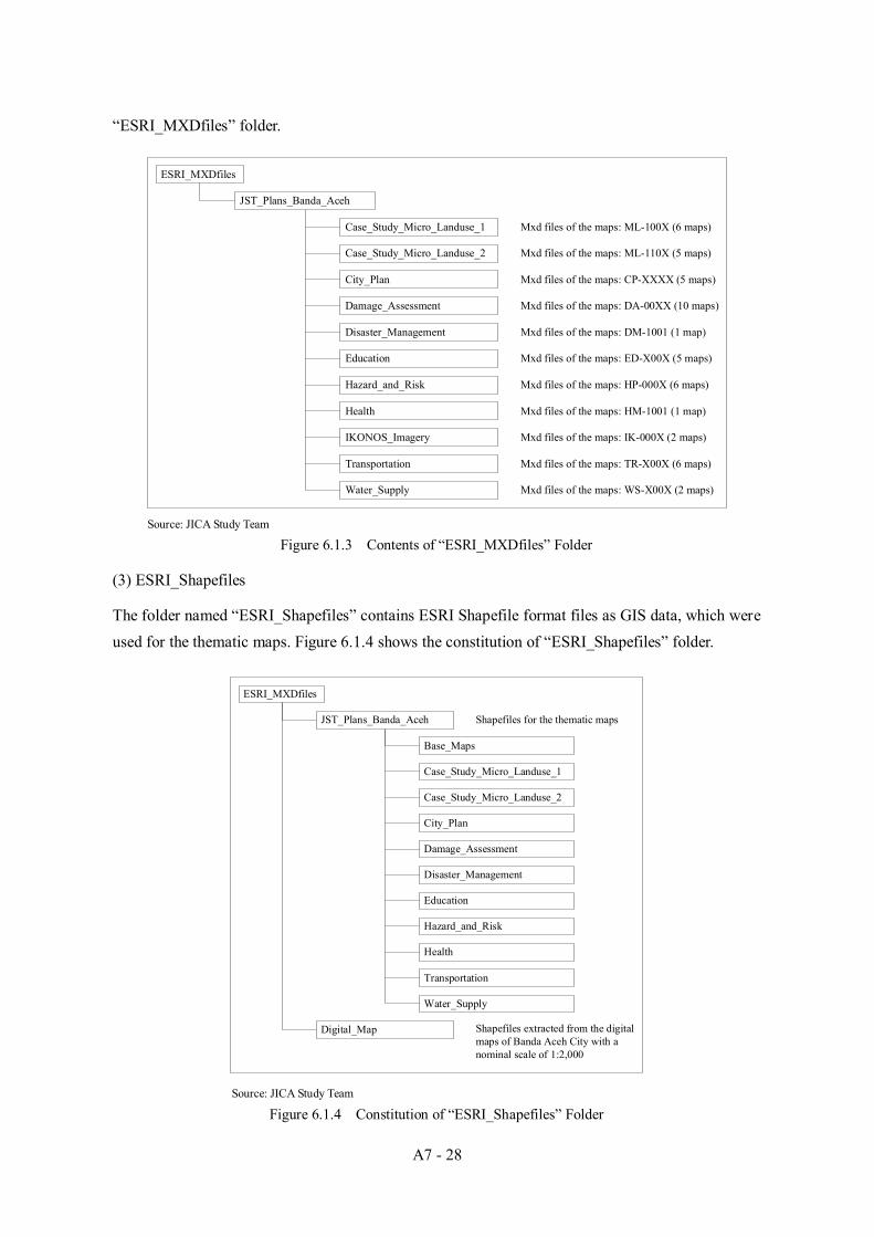
A7 - 28
“ESRI_MXDfiles” folder.
ESRI_MXDfiles
JST_Plans_Banda_Aceh
Case_Study_Micro_Landuse_1
Case_Study_Micro_Landuse_2
City_Plan
Damage_Assessment
Disaster_Management
Education
Hazard_and_Risk
Health
IKONOS_Imagery
Transportation
Water_Supply
Mxd files of the maps: ML-100X (6 maps)
Mxd files of the maps: ML-110X (5 maps)
Mxd files of the maps: CP-XXXX (5 maps)
Mxd files of the maps: DA-00XX (10 maps)
Mxd files of the maps: DM-1001 (1 map)
Mxd files of the maps: ED-X00X (5 maps)
Mxd files of the maps: HP-000X (6 maps)
Mxd files of the maps: HM-1001 (1 map)
Mxd files of the maps: IK-000X (2 maps)
Mxd files of the maps: TR-X00X (6 maps)
Mxd files of the maps: WS-X00X (2 maps)
Source: JICA Study Team
Figure 6.1.3 Contents of “ESRI_MXDfiles” Folder
(3) ESRI_Shapefiles
The folder named “ESRI_Shapefiles” contains ESRI Shapefile format files as GIS data, which were used for the thematic maps. Figure 6.1.4 shows the constitution of “ESRI_Shapefiles” folder.
ESRI_MXDfiles
JST_Plans_Banda_Aceh
Case_Study_Micro_Landuse_1
Case_Study_Micro_Landuse_2
City_Plan
Damage_Assessment
Disaster_Management
Education
Hazard_and_Risk
Health
Transportation
Water_Supply
Shapefiles for the thematic maps
Digital_Map
Base_Maps
Shapefiles extracted from the digital maps of Banda Aceh City with a nominal scale of 1:2,000
Source: JICA Study Team
Figure 6.1.4 Constitution of “ESRI_Shapefiles” Folder
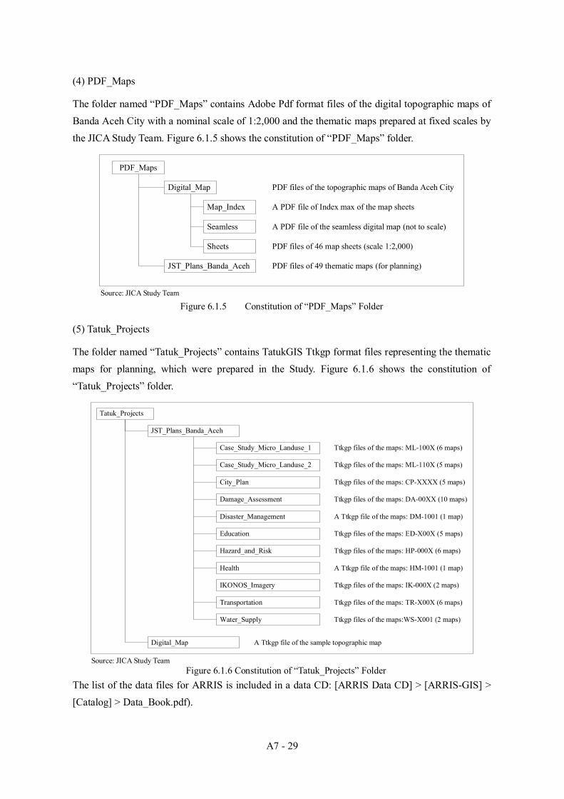
A7 - 29
(4) PDF_Maps
The folder named “PDF_Maps” contains Adobe Pdf format files of the digital topographic maps of Banda Aceh City with a nominal scale of 1:2,000 and the thematic maps prepared at fixed scales by the JICA Study Team. Figure 6.1.5 shows the constitution of “PDF_Maps” folder.
PDF_Maps
Digital_Map
JST_Plans_Banda_Aceh PDF files of 49 thematic maps (for planning)
Map_Index
Seamless
Sheets
A PDF file of Index max of the map sheets
A PDF file of the seamless digital map (not to scale)
PDF files of 46 map sheets (scale 1:2,000)
PDF files of the topographic maps of Banda Aceh City
Source: JICA Study Team
Figure 6.1.5 Constitution of “PDF_Maps” Folder
(5) Tatuk_Projects
The folder named “Tatuk_Projects” contains TatukGIS Ttkgp format files representing the thematic maps for planning, which were prepared in the Study. Figure 6.1.6 shows the constitution of “Tatuk_Projects” folder.
Tatuk_Projects
JST_Plans_Banda_Aceh
Case_Study_Micro_Landuse_1
Case_Study_Micro_Landuse_2
City_Plan
Damage_Assessment
Disaster_Management
Education
Hazard_and_Risk
Health
Transportation
Water_Supply
Digital_Map
Ttkgp files of the maps: ML-100X (6 maps)
Ttkgp files of the maps: ML-110X (5 maps)
Ttkgp files of the maps: CP-XXXX (5 maps)
Ttkgp files of the maps: DA-00XX (10 maps)
A Ttkgp file of the maps: DM-1001 (1 map)
Ttkgp files of the maps: ED-X00X (5 maps)
Ttkgp files of the maps: HP-000X (6 maps)
A Ttkgp file of the maps: HM-1001 (1 map)
Ttkgp files of the maps:WS-X001 (2 maps)
Ttkgp files of the maps: TR-X00X (6 maps)
A Ttkgp file of the sample topographic map
IKONOS_Imagery Ttkgp files of the maps: IK-000X (2 maps)
Source: JICA Study Team
Figure 6.1.6 Constitution of “Tatuk_Projects” Folder The list of the data files for ARRIS is included in a data CD: [ARRIS Data CD] > [ARRIS-GIS] > [Catalog] > Data_Book.pdf).

A7 - 30
6.2 METADATA OF ARRIS THEMATIC GIS LAYERS
The metadata of the thematic GIS layers are included in an ARRIS data CD. The metadata of the thematic GIS layers comprises of the following items.
Layer Name: name of the layer Feature Class: type of vector data (point, line, or polygon) Description: brief explanation of the layer Data Currency: currency of the layer Date of Ground Condition: date of ground condition included in the layer Stored Data Format: file format of the layer Projection/Datum: projection and datum applied for the layer Geographic Extent: geographic extent of the layer Targeted Mapping Scale: targeted mapping scales of the layer Meta Data Date: date of the metadata preparation Attributes, codes, and values: information on attribute tables
As for the shapefiles extracted from the digital maps of Banda Aceh City with a nominal scale of 1:2,000, the metadata are shown in “Feature Catalog” (APPENDIX-8).

A7 - 31
CHAPTER 7 PLANNING TOOLS FOR ARRIS USER In order to support the preparation of rehabilitation and reconstruction plans with a GIS in The Study, the JICA Study Team had developed the tools (ARRIS Tool) for the Study Team members, which are utilizable on ArcGIS (8.3 and later).
The ARRIS Tool enables not only the Study Team members but also other ArcGIS users to create buffer polygon features with ArcGIS, easily. Actually, buffer polygons were often created and used to plan public facilities/service areas through the JICA Study; e.g., schools, escape buildings/towers, case studies for micro land use plans. The tool can be customized by users who understand Visual Basic for Application (VBA) open source code.
7.1 OVERVIEW OF ARRIS TOOL
7.1.1 Main Functions
ARRIS Tool enables the users to support for four (4) city planning and disaster mitigation functions:
- Escape Building Planning - Road Planning - Health/Medical Planning - Education Planning - Creation of buffer zones from the user’s original point data.
7.1.2 Core Functions
The “Create Buffer” utility is a core function of the ARRIS Tool. This function generates buffer polygons using the planning base data or the user’s original point data (Figure 7.1.1).
User’s point
Buffer polygons Source: JICA Study Team
Figure 7.1.1 Concept on Creation of Buffer Polygons from User’s Points
7.2 SYSTEM SUMMARY
7.2.1 System Requirements
An ARRIS thematic map consists of an ESRI ArcMap Document file (*.mxd). Either ArcGIS Desktop version 8.3 or 9.0 (and later) can be used to run ARRIS Tool. The user must use either ARRIS_83.mxd for ArcGIS version 8.3 or ARRIS_90.mxd for ArcGIS version 9.0 and later. The

A7 - 32
same ESRI ArcMap Document file can not be shared by both versions. When a user runs ARRIS Tool, the user must ensure that the user uses the correct version of ArcGIS (8.3 or 9.0) with the matching ArcMap Document file.
7.2.2 System Architecture
ARRIS Tool are developed for ArcGIS Desktop. The tool requires ESRI Shapefiles for layers and an external Microsoft Access database (*.MDB) file for storing data settings (Figure 7.2.1).
ArcGIS Desktop
ESRI Shapefiles
External Mdb files
Source: JICA Study Team
Figure 7.2.1 Basic System Architecture
The data setting file (i.e. the external Microsoft Access database MDB file) used for ARRIS Tool must be always named “ARRISSetting.mdb”. This file can not be shared by different versions of the ARRIS ArcMap Document files (i.e. ARRIS_83.mxd or ARRIS_90.mxd) as mentioned above. In addition, when the user wants to make copies of the ARRIS “mxd” file, the user must copy the whole folder that includes both the ARRIS “mxd” file and the corresponding data setting file (ARRISSetting.mdb), as shown in Figure 7.2.2. If this is not done, the copied data will not work correctly in ARRIS.
A folder Another folder
Copy
Source: JICA Study Team
Table 7.2.2 How to Make Copy of Folder and Files for Tools

A7 - 33
7.3 OPERATION OF ARRIS TOOL (PART 1)
First of all, the user must place both ARRIS_83.mxd (or ARRIS_90.mxd) and ARRISsetting.mdb within a same folder as mentioned above.
7.3.1 Starting ARRIS Tool
The user must double click the icon (ARRIS_83.mxd or ARRIS_90.mxd) displayed in a computer window to activate the tools.
Source:JICA Study Team
Figure 7.3.1 ARRIS_83.mxd (ARRIS_90.mxd) Icon
7.3.2 ARRIS Tool Screen Contents
Figure 7.3.2 shows a screen view appears when the user opens ARRIS_83.mxd or ARRIS_90.mxd.
Map Window
Toolbars
Table of Contents
Layers
Menu: “ARRIS”
Menu: “Planning”
Source: JICA Study Team
Figure 7.3.2 Screen Contents of ARRIS_83 (90).mxd

A7 - 34
7.3.3 Items in Menu
When ARRIS_83.mxd or ARRIS_90.mxd is opened by the user, two (2) menu items ([ARRIS] and [Planning]) are automatically added to the ArcGIS Desktop menu bar.
Table 7.3.1 shows the descriptions on the contents of the additional menu for the tools.
Table 7.3.1 Additional Menu Items for Tools
[ARRIS] Menu
Menu items for setting data for each tool.
Menu items for saving/loading settings.
Menu item for starting the Administrative Boundary Selector tool.
[Planning] Menu
Menu item for adding a User’s point layer. (It has sub-menu items.)
Menu items for the Planning Tools.
Source: JICA Study Team
7.3.4 Closing ARRIS Tool
Table 7.3.2 shows how to finish the utilization of the tools.
Table 7.3.2 How to Close Tools
a) Click on [File] on the main tool bar.
b) Select [Exit] on the File sub-menu.
NOTE: The system can be finished with or without saving
the ArcMap Document file (*.mxd).
Source: JICA Study Team

A7 - 35
7.4 OPERATION OF ARRIS TOOL (PART 2)
ARRIS Tool includes the three (3) modules as follows:
Administrative Boundary Selector Tool Sector Planning Tool Create Buffer Polygon Tool (using the user’s specifying points)
7.4.1 Administrative Boundary Selector Module
There are administrative boundaries like “desa” and “kecamatan” within Banda Aceh City. When using ArcGIS, many steps are required to select and zoom in to a specified boundary feature. With ARRIS Tool, this task is simplified by using the Administrative Boundary Selector module. This module allows easy selection and zooming to a user-specified administrative boundary.
(1) Operation Flow
Figure 7.4.1 shows the operation flow of the Administrative Boundary Selector module.
Click Menu.Select a
administrative boundary (feature).
Administrative boundary layer(s) loaded?
Automatically zoom in to the
selected feature.
Load administrative boundary layer(s).
No
Yes
Source: JICA Study Team
Figure 7.4.1 Operation Flow of Administrative Boundary Selector
(2) Zooming to an Administrative Boundary (Kecamatan / Desa)
1) Selecting “Administrative Boundary Selector”in [ARRIS] menu.
Source: JICA Study Team
Figure 7.4.2 Administrative Boundary Selector in [ARRIS] Menu

A7 - 36
2) Then a dialog window is shown as Figure 7.4.3.
Source: JICA Study Team
Figure 7.4.3 Administrative Boundary Layer Selection Dialog (Window)
If both a kecamatan and a desa layer are not already in the TOC, a warning message appears. The “Administrative Boundary Layer Selection” dialog will open after this warning message is dismissed. (This dialog will not appear if both a Kecamatan and a Desa layer are already present in the TOC.)
3) To load a kecamatan layer, click on the Open Folder button ( ) and choose a Kecamatan layer (Shapefile). Repeat this for the desa layer (Shapefile). After choosing the required layers, click on the “Close” button.
4) If both a kecamatan and a desa layer are present in the TOC, the “Zoom to a Specific kecamatan and Desa” window will open (Figure 7.4.4). This window allows a specific kecamatan and desa to be selected (NOTE: The list of available desa is dependent upon the kecamatan that is selected. (The required desa must be located in the selected kecamatan.)).
Source: JICA Study Team
Figure 7.4.4 Zoom to a Specific Kecamatan and Desa Dialog (Window)
5) The map window will automatically zoom to the full extent of the selected kecamatan (polygon feature). The desa list will also be updated. This list will show all desa names in the selected kecamatan.
(3) Other Functions – Layer and Label Visibility The Administrative Boundary dialog has functions for changing the visibility of layers and labels of the features (Figure 7.4.5).
1) By clicking the Layer Visibility button to toggle the layer visibility on or off 2) By toggling the Label Visibility button turns the labels on or off

A7 - 37
Layer Visibility Button
Label Visibility Button
Source: JICA Study Team
Figure 7.4.5 Label Visibility Button and Layer Visibility Button
To show labels, the user is required to set a field (attribute) to use for the label before enabling the Label Visibility function as follows:
1) Double click on the layer in the TOC window; 2) Click on the Labels tab on Layer Properties dialog; 3) Choose a field name in the Label Field list; and 4) Click the OK button.
7.4.2 Sector Planning Modules (Data Setting)
In order to create buffer polygons for some sector plans, the base data have to be loaded before the tool will work. The main function of the tools is to create buffers for the base data.
Table 7.4.1 Tools for Creation of Buffer Polygons
Sector Planning Module Base Data Examples Feature Layer Type Escape Building Planning Module
-Candidate building(s) -Existing escape building(s)
Point
Road Planning Module -Existing road(s) -Planned road(s)
Polyline
Health/Medical Planning Module
-Hospital(s) -Medical Center(s)
Point
Education Planning Module -Elementary school(s) -Junior high school(s) -Senior high school(s)
Point
Source: JICA Study Team
In addition, settings can be stored in an external database (*.mdb) file. The following steps describe how to set the base data for the tools for creation of buffer polygons, and how to save/load the settings stored in the external database file.

A7 - 38
(1) Operation Flow
Figure 7.4.6 shows the operation flow of the data setting for the Sector Planning Modules.
Click Menu. Automatically assign the data layer into ARRIS Tool.
Load feature layer(s) (shapefile).
* Loading a feature layer from the existing layers in the TOC is not supported.
Source: JICA Study Team
Figure 7.4.6 Operation Flow for Sector Planning Modules
(2) Setting Base Data for Sector Planning Modules
Below describes how to set the base data for the Escape Building Planning Module. The procedure for setting all four (4) planning modules works in the same way.
1) Clicking on “Set Escape Building Data” in the Planning menu: “Open Point Layer” dialog will be displayed. The Open Point Layer dialog will also be displayed when setting the Health/Medical Planning Tool and the Education Planning Tool, as these are also point feature layers. However, an “Open Polyline Layer” dialog will be displayed when setting the Road Planning Tool, as the roads are polyline feature layers.
2) Loading the Feature Layer (Shapefile) Choosing a point feature layer (Shapefile) as the base data for the Escape Building Planning Tool. After choosing it, click the “Add” button in the dialog window.
3) Assigning the Data Layer to the Planning Tool automatically The selected layer will automatically be assigned to the Escape Building Planning Tool. The user can set the symbols for the selected layer as desired.
(3) Save/Load Data Settings
The sector planning modules allow the user to save the current planning data settings in an external file, and load the settings again at another time. This is done as follows:
1) Clicking on “Save Settings” in the ARRIS menu; A confirmation message will appear (and by clicking on the “OK” button to continue; Figure 7.4.7).
Source: JICA Study Team
Figure 7.4.7 Confirmation and Error Message Windows in Saving Data Settings

A7 - 39
2) Settings are stored; The settings are stored in an external MDB file. If one or more planning tool(s) has no base data, an error message will appear (Figure 7.4.7).
3) Clicking on “Load Settings” in the ARRIS menu; A Confirmation message will appear (and by clicking on “OK” to continue; Figure 7.4.8).
Source: JICA Study Team
Figure 7.4.8 Confirmation and Error Message Windows in Loading Data Settings
4) Settings are loaded; The settings are loaded from an external MDB file. If the external MDB file does not contain setting for one or more planning tools, an error message will appear (Figure 7.13).
7.5 SECTOR PLANNING MODULE (Manipulation)
7.5.1 Escape Building Planning Module
(1) Operation Flow
Figure 7.5.1 shows the operation flow for Escape Building Planning Module.
Click Menu. Draw buffer function.
Escape buildings layer loaded?
Change buffer layer symbology (option).
Terminate.
No
Yes
Source: JICA Study Team
Figure 7.5.1 Operation Flow for Sector Planning Modules
(1) Manipulation of Escape Building Planning Module (2) Clicking on “Escape Building Planning” in the Planning menu;
“Draw Buffer” dialog opens (Figure 7.5.2). To create a new buffer feature layer (Shapefile), choose “Create New Buffer” and specify the new shapefile name in the “Save Shapefile”
dialog. This dialog is opened by clicking on the Open Folder button ( ). To load an existing feature layer (Shapefile), choose “Append to Existing Buffer” and specify the existing Shapefile name in the “Open Polygon Layer” dialog. This dialog is opened by
clicking on the Open Folder button ( ). Alternatively, choose the polygon layer from the combo box. By clicking on the “Next>” button, the user can proceed to the next step.

A7 - 40
Source: JICA Study Team
Figure 7.5.2 “Draw Buffer” Dialog Window
If the Escape Building Planning module has no base data, an error message appears (Figure 7.5.3).
Source: JICA Study Team
Figure 7.5.3 “Error Message” Dialog Window
2) Selecting features for buffering; The user selects feature(s) for generating buffers. The “Select Features” tool and “Select By Attributes” tool are available for selecting features (Figure 7.5.4), if required (for details about using the “Select Feature” tools, please refer to the ArcGIS on-line Help). By clicking on the “Next>” button, the user can proceed to the next step.
Source: JICA Study Team
Figure 7.5.4 “Select Features” and “Select by Attributes” Dialog Window
3) Inputting a buffer distance; The user input the buffer distance value (m). The value must be a numerical value. By clicking on the “Draw” button, the user can draw the buffers (Figure 7.5.5).

A7 - 41
Source: JICA Study Team
Figure 7.5.5 “Input Buffer Distance” Dialog Window
4) Choosing “save” or “discard” the generated buffer; The user clicks on the “Yes” button to store the generated buffer in the buffer feature layer. If the user clicks on the “No” button, the generated buffer is discarded (Figure 7.5.6).
Source: JICA Study Team
Figure 7.5.6 “Save Drawn Buffers” Dialog Window
5) Continuing creation of buffer polygons; By clicking on the “Yes” button, the user can continue creating buffers. This will allow you to add more buffer polygons by repeating the Create Buffer procedure. Alternatively, if the user wants to finish creating buffer polygons, the user may click on the “No” button to terminate the generation of the buffer polygons (Figure 7.5.7).
Source: JICA Study Team
Figure 7.5.7 “Continue to Create Buffers?” Dialog Window
6) Changing the buffer layer symbology (option); If desired, the user can change layer symbol for a better appearance. For details about changing the layer symbology, please refer to the ArcGIS on-line Help.
7.5.2 Road Planning Module
(1) Operation Flow
Figure 7.5.8 shows the operation flow for Road Planning Module.

A7 - 42
Click Menu. Draw buffer function.
A road planning layer loaded?
Change buffer layer symbology (option).
Terminate.
No
Yes
Source: JICA Study Team
Figure 7.5.8 Operation flow for Road Planning Module
(2) Manipulation of Road Planning Module
The Road Planning Module is used in a very similar way to the Escape Building Planning Tool mentioned above. However, because the roads are represented as polylines, a buffer is drawn parallel to the road. The buffer is formed as a series of merged circles, so the buffer is not exactly parallel to the road (line) that is being buffered.
7.5.3 Health/Medical Planning Module
(1) Operation Flow
Figure 7.5.9 below shows the operation flow for Health/Medical Planning Module.
Click Menu. Draw buffer function.
A health planning layer loaded?
Change buffer layer symbology (option).
Terminate.
No
Yes
Source: JICA Study Team
Figure 7.5.9 Operation Flow for Road Planning Module
(2) Manipulation of Health/Medical Planning Module
The Health/Medical Planning Module is used in a very similar way to the Escape Building Planning Tool.

A7 - 43
7.5.4 Education Planning Module
(1) Operation Flow
Figure 7.5.10 below shows the operation flow for the Education Planning Module.
Click Menu. Draw buffer function.
An educational planning layer loaded?
Change buffer layer symbology (option).
Terminate.
No
Yes
Source: JICA Study Team
Figure 7.5.10 Operation flow for Education Planning Module
(2) Manipulation of Education Planning Module
The Education Planning Module is used in a very similar way to the Escape Building Planning Tool.
7.6 CREATE BUFFER POLYGON MODULE
7.6.1 User Point Layer Tool
The “User’s Point Layer Tool” contains three functions (Figure 7.6.1)
Add User’s Point Layer To add a User’s point feature layer (Shapefile) from an existing file, or create a new Shapefile.
Start/Stop Editing User’s Point: To start/stop editing the User’s point feature layer; this function acts in the same way as the “Start Editing” and “Stop Editing” tool on the standard ArcGIS Edit toolbar.
Create Buffer To create buffers for the User’s point feature layer.
Source: JICA Study Team
Figure 7.6.1 Items in “User’s Point Layer” Sub-menu
7.6.2 Add User’s Point Layer
This function is used to add a user’s point feature layer (Shapefile) from existing Shapefile, or create a new Shapefile.

A7 - 44
1) Clicking on “Add User’s Point Layer” in “User’s Point Layer” menu (Figure 7.6.2);
The Add Layer dialog will open. The user must choose “Create New Shapefile” if the user wants to
create a new Shapefile, or the user must choose “Load Existing Shapefile” if the user already has a
shapefile that the wants to use as a User’s point feature layer.
Next, the user specifies the shapefile name. In order to specify the shapefile, the user clicks on the
“…” button. The Open Point Layer dialog will be displayed. After choosing the desired shapefile,
the user clicks on the “Add” button.
If the users chooses “Load Existing Shapefile” (see above), this procedure is finished. However,
if the user chooses “Create New Shapefile”, the user proceeds to the next step.
Add Layer dialog Open Point Layer dialog Source: JICA Study Team
Figure 7.6.2 “Add Layer” Dialog and “Open Point Layer” Dialog Windows
2) Creating attribute fields for a new shapefile; Each Shapefile must have at least one attribute field. Some examples of typical attributes are as follows:
Data Name Type: String
Precision: Number of characters (for text field width) Buffer Distance
Type: Integer or Long Integer Precision: Number of digits (for integer number size) After creating attribute fields, the user clicks on the “Finish” button (Figure 7.6.3). A new Shapefile will be created and automatically loaded into the TOC of ArcGIS.
Source: JICA Study Team
Figure 7.6.3 User Dialog for Specifying Attributes of a New Shapefile

A7 - 45
7.6.3 Add User’s Point Layer
A User’s point feature layer can be edited by the user. To start or stop an editing task, the user clicks on “Start/Stop Editing User’s Point” in the User’s Point Layer menu (a Planning menu option).
For details about point feature editing, please refer to the ArcGIS on-line Help.
7.6.4 Creating Buffer Polygons for a User’s Point Layer
1) The user clicks on “Create Buffer” in the “User’s Point Layer” menu; The Draw Buffer dialog will open (Figure 7.6.4). To create a new buffer feature layer (Shapefile), the user chooses “Create New Buffer” and specifies the new shapefile name in the
“Save Shapefile” dialog. This dialog is opened by clicking on the Open Folder button ( ).
Source: JICA Study Team
Figure 7.6.4 “Draw Buffer” Dialog Window
To load an existing feature layer (Shapefile), the user chooses “Append to Existing Buffer” (Figure 7.6.4) and specify the existing shapefile name by selecting it from the “Open Polygon Layer”. The dialog is opened by clicking on open folder button (see above). Alternatively, the user can chooses the polygon layer from the combo box. By clicking on the “Next>” button, the user can proceed to the next step. If no user’s point layer is added, an error message will appear (Figure 7.6.5).
Source: JICA Study Team
Figure 7.6.5 “Error Message” Dialog Window
2) Select features for buffering; The user selects the point feature(s) for use in generating a buffer. The ”Select Features” tool and “Select By Attributes” tools are available for selecting features (Figure 7.6.6).

A7 - 46
Source: JICA Study Team
Figure 7.6.6 “Select Feature(s)” Dialog Window
For details about using the “Select Feature” tools, the user should refer to the ArcGIS on-line Help. By clicking on the “Next>” button, the user proceeds to the next step. 3) Inputting the buffer distance;
The user enters a buffer distance value (meters). The value must be numerical value. By clicking on the “Draw” button, the user can draw the buffers (Figure 7.6.7).
Source: JICA Study Team
Figure 7.6.7 “Input Buffer Distance” Dialog Window
4) Clicking on the “Yes” button to store the generated buffer in the buffer feature layer. Alternatively, the user can click on the “No” button to discard the generated buffer (Figure 7.6.8).
Source: JICA Study Team
Figure 7.6.8 “Input Buffer Distance” Dialog Window
5) By clicking on the “Yes” button, the user can continue creating buffers. This will allow the user to add more buffers by repeating the Create Buffer procedure mentioned above. Alternatively, if the user have finished creating buffers, the user can click on the “No” button to terminate the Create Buffer function (Figure 7.6.9).

A7 - 47
Source: JICA Study Team
Figure 7.6.9 “Continue to create buffers?” Dialog Window

A7 - 48
CHAPTER 8 PRESENTATION AND DEMONSTRATION OF ARRIS
Presentation and demonstration of ARRIS were conducted in the course of the Study as follows:
I. (1) Date: April 21, 2005 (2) Venue: BAPPEDA Province Office, NAD. (3) Who/Presenter: GIS Expert (JICA Study Team). (4) What: Basics of ArcGIS Software: Basic skills for ArcGIS users (manipulation of
menus and tools in ArcGIS, registration of base map image data, digitization of spatial data, questions and answers).
(5) Why: The training was requested by BAPPEDA Province because ArcGIS has never been used in BAPPEDA Province.
(6) Participants (to whom): Mr. Chandler (Staff member responsible for GIS in BAPPEDA Province, NAD).
(7) How: Man-to-man training using ArcGIS software (seven hours).
II. (1) Date: April 28, 2005 (2) Venue: City Office, Banda Aceh City. (3) Who/Presenter: GIS Expert (JICA Study Team). (4) What: Basic Version of ARRIS: Plans for ARRIS, introduction of GIS technology,
contents of the GIS database for the Basic Version of ARRIS, questions and answers about the presentation.
(5) Why: To inform the stakeholders working in Banda Aceh City about the content of the Basic Version of ARRIS.
(6) Participants (to whom): Governmental officers and international organizations/donors were invited (about 30 participants).
(7) How: Presentations using PowerPoint, and demonstration of ARRIS using GIS software (approximately 30 minutes).
III. (1) Date: May 3, 2005 (2) Venue: BAPPENAS, Jakarta. (3) Who/Presenter: GIS Expert (JICA Study Team). (4) What: Basic Version of ARRIS: Plans for ARRIS, introduction of GIS technology,
contents of the GIS database for the Basic Version of ARRIS, and questions and answers about the presentation.
(5) Why: To inform the stakeholders working in Banda Aceh City about the contents of the Basic Version of ARRIS.
(6) Participants (to whom): Governmental officers (BAPPENAS, BPN, BAKOSURTANAL, Ministry of Public Works), UNDP, ADB, JICA Indonesia

A7 - 49
Office, etc. (approximately 20 participants). (7) How: Presentation using PowerPoint, and demonstration of ARRIS using GIS
software (approximately 90 minutes).
IV. (1) Date: December 22, 2005 (2) Venue: Syiah Kuala University (SKU), Banda Aceh City. (3) Who/Presenter: GIS Expert (JICA Study Team). (4) What: Complete Version of ARRIS: Objectives and overview of ARRIS, thematic
maps and (GIS) layers in ARRIS, GIS database in ARRIS, trial use of ARRIS data with digital maps of Banda Aceh City, customized tools for ARRIS, announcement about ARRIS data distribution, questions and answers.
(5) Why: To inform the stakeholders working in Banda Aceh City about the contents of the complete version of ARRIS, including the digital maps of Banda Aceh City which have a nominal scale of 1:2,000.
(6) Participants (to whom): Governmental officers (BAPPEDA, BRR, BAPPEADALDA, Dinas Tata Kota), international organizations/donors, NGO, SKU students, and residents in Banda Aceh City (approximately 50 participants).
(7) How: Presentation using PowerPoint and posters, demonstration of ARRIS using GIS (approximately 180 minutes).
V. (1) Date: January 18, 2006 (2) Venue: BAPPENAS, Jakarta. (3) Who/Presenter: GIS Expert (JICA Study Team), Mr. Luky Eko W. (BAPPENAS). (4) What: Complete Version of ARRIS: Introduction of the JICA Study for URRP,
objectives and overview of ARRIS, thematic maps and (GIS) layers in ARRIS, GIS database in ARRIS, customized tools for ARRIS, announcement about ARRIS data distribution, questions and answers.
(5) Why: To inform the stakeholders working in Banda Aceh City about the contents of the complete version of ARRIS, including the digital maps of Banda Aceh City which have a nominal scale of 1:2,000.
(6) Participants (to whom): Governmental officers (BAPPENAS, BRR, BAKOSURTANAL, the line ministries), international organizations/donors, JICA Indonesian Office (approximately 25 participants).
(7) How: Presentation using PowerPoint and posters, demonstration of ARRIS using GIS (approximately 90 minutes).
VI. (1) Date: January 27, 2006 (2) Venue: Syiah Kuala University, Banda Aceh City. (3) Who/Presenter: GIS Expert (JICA Study Team), Mr.Eddy Purwanto (BRR), and
Mr. Mr.Muzailin (SKU). (4) What: Complete Version of ARRIS: Introduction of the JICA Study for URRP,

A7 - 50
objectives and overview of ARRIS, thematic maps and (GIS) layers in ARRIS, GIS databases in ARRIS, announcement about ARRIS data distribution, questions and answers.
(5) Why: To inform the stakeholders working in Banda Aceh City about the content of the complete version of ARRIS, including the digital maps of Banda Aceh City which have a nominal scale of 1:2,000.
(6) Participants (to whom): Governmental officers (BRR, BAPPEDA, BAPPEDALDA, Dinas Tata Kota, etc.), international organizations/donors (World Bank, ADB, WHO, GTZ, etc.), NGOs, JICA (approximately 60 participants).
(7) How: Presentation using PowerPoint and posters, demonstration of ARRIS using GIS (approximately 90 minutes).